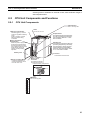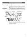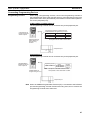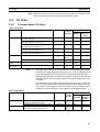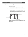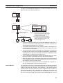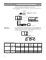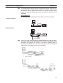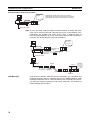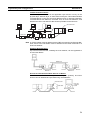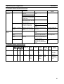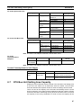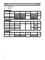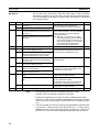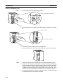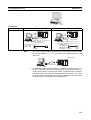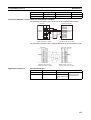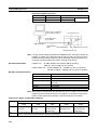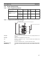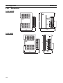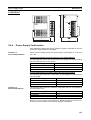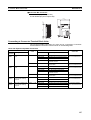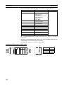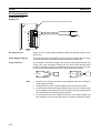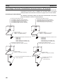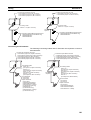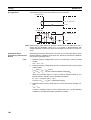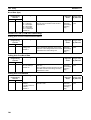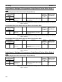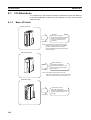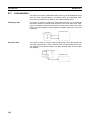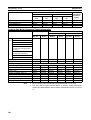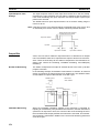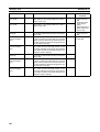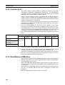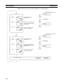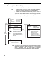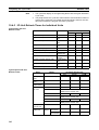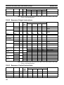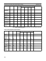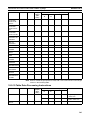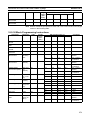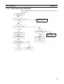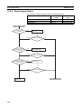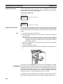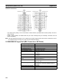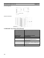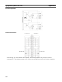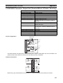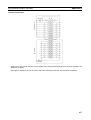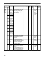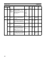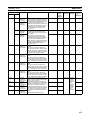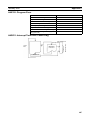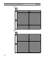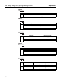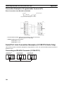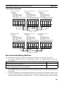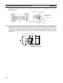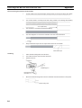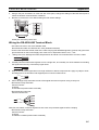
1
Cat. No. W393-E1-03 SYSMAC CJ Series CJ1G/H-CPU@@H, CJ1M-CPU@@, CJ1G-CPU@@ Programmable Controllers OPERATION MANUAL SYSMAC CJ Series CJ1G/H-CPU@@H, CJ1M-CPU@@, CJ1G-CPU@@ Programmable Controllers Operation Manual Revised July 2002 iv Notice: OMRON products are manufactured for use according to proper procedures by a qualified operator and only for the purposes described in this manual. The following conventions are used to indicate and classify precautions in this manual. Always heed the information provided with them. Failure to heed precautions can result in injury to people or damage to property. !DANGER Indicates an imminently hazardous situation which, if not avoided, will result in death or serious injury. !WARNING Indicates a potentially hazardous situation which, if not avoided, could result in death or serious injury. !Caution Indicates a potentially hazardous situation which, if not avoided, may result in minor or moderate injury, or property damage. OMRON Product References All OMRON products are capitalized in this manual. The word “Unit” is also capitalized when it refers to an OMRON product, regardless of whether or not it appears in the proper name of the product. The abbreviation “Ch,” which appears in some displays and on some OMRON products, often means “word” and is abbreviated “Wd” in documentation in this sense. The abbreviation “PLC” means Programmable Controller. “PC” is used, however, in some Programming Device displays to mean Programmable Controller. Visual Aids The following headings appear in the left column of the manual to help you locate different types of information. Note Indicates information of particular interest for efficient and convenient operation of the product. 1,2,3... 1. Indicates lists of one sort or another, such as procedures, checklists, etc. OMRON, 2001 All rights reserved. No part of this publication may be reproduced, stored in a retrieval system, or transmitted, in any form, or by any means, mechanical, electronic, photocopying, recording, or otherwise, without the prior written permission of OMRON. No patent liability is assumed with respect to the use of the information contained herein. Moreover, because OMRON is constantly striving to improve its high-quality products, the information contained in this manual is subject to change without notice. Every precaution has been taken in the preparation of this manual. Nevertheless, OMRON assumes no responsibility for errors or omissions. Neither is any liability assumed for damages resulting from the use of the information contained in this publication. v vi TABLE OF CONTENTS PRECAUTIONS . . . . . . . . . . . . . . . . . . . . . . . . . . . . . . . . . . . xiii 1 Intended Audience . . . . . . . . . . . . . . . . . . . . . . . . . . . . . . . . . . . . . . . . . . . . . . . . . . . . . . . . xiv 2 General Precautions . . . . . . . . . . . . . . . . . . . . . . . . . . . . . . . . . . . . . . . . . . . . . . . . . . . . . . . xiv 3 Safety Precautions. . . . . . . . . . . . . . . . . . . . . . . . . . . . . . . . . . . . . . . . . . . . . . . . . . . . . . . . . xiv 4 Operating Environment Precautions . . . . . . . . . . . . . . . . . . . . . . . . . . . . . . . . . . . . . . . . . . . xvi 5 Application Precautions . . . . . . . . . . . . . . . . . . . . . . . . . . . . . . . . . . . . . . . . . . . . . . . . . . . . xvi 6 Conformance to EC Directives . . . . . . . . . . . . . . . . . . . . . . . . . . . . . . . . . . . . . . . . . . . . . . . xx SECTION 1 Introduction . . . . . . . . . . . . . . . . . . . . . . . . . . . . . . . . . . . . . . 1 1-1 Overview . . . . . . . . . . . . . . . . . . . . . . . . . . . . . . . . . . . . . . . . . . . . . . . . . . . . . . . . . . . . . . . . 2 1-2 CJ-series Features . . . . . . . . . . . . . . . . . . . . . . . . . . . . . . . . . . . . . . . . . . . . . . . . . . . . . . . . . 3 1-3 CJ1-H and CJ1M CPU Unit Features . . . . . . . . . . . . . . . . . . . . . . . . . . . . . . . . . . . . . . . . . . 12 1-4 CJ1 and CJ1-H CPU Unit Comparison. . . . . . . . . . . . . . . . . . . . . . . . . . . . . . . . . . . . . . . . . 18 1-5 Function Tables . . . . . . . . . . . . . . . . . . . . . . . . . . . . . . . . . . . . . . . . . . . . . . . . . . . . . . . . . . . 23 1-6 CJ1-H Functions Arranged by Purpose . . . . . . . . . . . . . . . . . . . . . . . . . . . . . . . . . . . . . . . . 32 1-7 CJ1M Functions Arranged by Purpose . . . . . . . . . . . . . . . . . . . . . . . . . . . . . . . . . . . . . . . . . 35 1-8 Comparison to CS-series PLCs. . . . . . . . . . . . . . . . . . . . . . . . . . . . . . . . . . . . . . . . . . . . . . . 40 SECTION 2 Specifications and System Configuration. . . . . . . . . . . . . . . 43 2-1 Specifications . . . . . . . . . . . . . . . . . . . . . . . . . . . . . . . . . . . . . . . . . . . . . . . . . . . . . . . . . . . . 44 2-2 CPU Unit Components and Functions . . . . . . . . . . . . . . . . . . . . . . . . . . . . . . . . . . . . . . . . . 55 2-3 Basic System Configuration . . . . . . . . . . . . . . . . . . . . . . . . . . . . . . . . . . . . . . . . . . . . . . . . . 59 2-4 I/O Units . . . . . . . . . . . . . . . . . . . . . . . . . . . . . . . . . . . . . . . . . . . . . . . . . . . . . . . . . . . . . . . . 67 2-5 Expanded System Configuration . . . . . . . . . . . . . . . . . . . . . . . . . . . . . . . . . . . . . . . . . . . . . 71 2-6 Unit Current Consumption . . . . . . . . . . . . . . . . . . . . . . . . . . . . . . . . . . . . . . . . . . . . . . . . . . 84 2-7 CPU Bus Unit Setting Area Capacity . . . . . . . . . . . . . . . . . . . . . . . . . . . . . . . . . . . . . . . . . . 87 2-8 I/O Table Settings List . . . . . . . . . . . . . . . . . . . . . . . . . . . . . . . . . . . . . . . . . . . . . . . . . . . . . 88 SECTION 3 Nomenclature, Functions, and Dimensions . . . . . . . . . . . . . 91 3-1 CPU Units . . . . . . . . . . . . . . . . . . . . . . . . . . . . . . . . . . . . . . . . . . . . . . . . . . . . . . . . . . . . . . . 92 3-2 File Memory . . . . . . . . . . . . . . . . . . . . . . . . . . . . . . . . . . . . . . . . . . . . . . . . . . . . . . . . . . . . . 100 3-3 Programming Devices. . . . . . . . . . . . . . . . . . . . . . . . . . . . . . . . . . . . . . . . . . . . . . . . . . . . . . 107 3-4 Power Supply Units . . . . . . . . . . . . . . . . . . . . . . . . . . . . . . . . . . . . . . . . . . . . . . . . . . . . . . . 117 3-5 I/O Control Units and I/O Interface Units . . . . . . . . . . . . . . . . . . . . . . . . . . . . . . . . . . . . . . 120 3-6 CJ-series Basic I/O Units . . . . . . . . . . . . . . . . . . . . . . . . . . . . . . . . . . . . . . . . . . . . . . . . . . . 121 vii TABLE OF CONTENTS SECTION 4 Operating Procedures . . . . . . . . . . . . . . . . . . . . . . . . . . . . . . 131 4-1 Introduction . . . . . . . . . . . . . . . . . . . . . . . . . . . . . . . . . . . . . . . . . . . . . . . . . . . . . . . . . . . . . . 132 4-2 Examples . . . . . . . . . . . . . . . . . . . . . . . . . . . . . . . . . . . . . . . . . . . . . . . . . . . . . . . . . . . . . . . . 134 SECTION 5 Installation and Wiring . . . . . . . . . . . . . . . . . . . . . . . . . . . . . 145 5-1 Fail-safe Circuits . . . . . . . . . . . . . . . . . . . . . . . . . . . . . . . . . . . . . . . . . . . . . . . . . . . . . . . . . . 146 5-2 Installation. . . . . . . . . . . . . . . . . . . . . . . . . . . . . . . . . . . . . . . . . . . . . . . . . . . . . . . . . . . . . . . 148 5-3 Wiring . . . . . . . . . . . . . . . . . . . . . . . . . . . . . . . . . . . . . . . . . . . . . . . . . . . . . . . . . . . . . . . . . . 170 SECTION 6 DIP Switch Settings . . . . . . . . . . . . . . . . . . . . . . . . . . . . . . . . 189 6-1 Overview . . . . . . . . . . . . . . . . . . . . . . . . . . . . . . . . . . . . . . . . . . . . . . . . . . . . . . . . . . . . . . . . 190 6-2 Details . . . . . . . . . . . . . . . . . . . . . . . . . . . . . . . . . . . . . . . . . . . . . . . . . . . . . . . . . . . . . . . . . . 191 SECTION 7 PLC Setup . . . . . . . . . . . . . . . . . . . . . . . . . . . . . . . . . . . . . . . . 193 7-1 PLC Setup . . . . . . . . . . . . . . . . . . . . . . . . . . . . . . . . . . . . . . . . . . . . . . . . . . . . . . . . . . . . . . . 194 7-2 Explanations of PLC Setup Settings . . . . . . . . . . . . . . . . . . . . . . . . . . . . . . . . . . . . . . . . . . . 227 SECTION 8 I/O Allocations and Data Exchange . . . . . . . . . . . . . . . . . . . 237 8-1 I/O Allocations . . . . . . . . . . . . . . . . . . . . . . . . . . . . . . . . . . . . . . . . . . . . . . . . . . . . . . . . . . . 238 8-2 Data Exchange with CPU Bus Units. . . . . . . . . . . . . . . . . . . . . . . . . . . . . . . . . . . . . . . . . . . 252 SECTION 9 Memory Areas . . . . . . . . . . . . . . . . . . . . . . . . . . . . . . . . . . . . 257 viii 9-1 Introduction . . . . . . . . . . . . . . . . . . . . . . . . . . . . . . . . . . . . . . . . . . . . . . . . . . . . . . . . . . . . . . 258 9-2 I/O Memory Areas . . . . . . . . . . . . . . . . . . . . . . . . . . . . . . . . . . . . . . . . . . . . . . . . . . . . . . . . 259 9-3 I/O Area. . . . . . . . . . . . . . . . . . . . . . . . . . . . . . . . . . . . . . . . . . . . . . . . . . . . . . . . . . . . . . . . . 267 9-4 Data Link Area . . . . . . . . . . . . . . . . . . . . . . . . . . . . . . . . . . . . . . . . . . . . . . . . . . . . . . . . . . . 272 9-5 CPU Bus Unit Area. . . . . . . . . . . . . . . . . . . . . . . . . . . . . . . . . . . . . . . . . . . . . . . . . . . . . . . . 273 9-6 Special I/O Unit Area . . . . . . . . . . . . . . . . . . . . . . . . . . . . . . . . . . . . . . . . . . . . . . . . . . . . . . 274 9-7 Serial PLC Link Area . . . . . . . . . . . . . . . . . . . . . . . . . . . . . . . . . . . . . . . . . . . . . . . . . . . . . . 276 9-8 DeviceNet Area. . . . . . . . . . . . . . . . . . . . . . . . . . . . . . . . . . . . . . . . . . . . . . . . . . . . . . . . . . . 277 9-9 Internal I/O Area . . . . . . . . . . . . . . . . . . . . . . . . . . . . . . . . . . . . . . . . . . . . . . . . . . . . . . . . . . 278 9-10 Holding Area. . . . . . . . . . . . . . . . . . . . . . . . . . . . . . . . . . . . . . . . . . . . . . . . . . . . . . . . . . . . . 279 9-11 Auxiliary Area. . . . . . . . . . . . . . . . . . . . . . . . . . . . . . . . . . . . . . . . . . . . . . . . . . . . . . . . . . . . 280 9-12 TR (Temporary Relay) Area . . . . . . . . . . . . . . . . . . . . . . . . . . . . . . . . . . . . . . . . . . . . . . . . . 303 9-13 Timer Area . . . . . . . . . . . . . . . . . . . . . . . . . . . . . . . . . . . . . . . . . . . . . . . . . . . . . . . . . . . . . . 304 TABLE OF CONTENTS 9-14 Counter Area . . . . . . . . . . . . . . . . . . . . . . . . . . . . . . . . . . . . . . . . . . . . . . . . . . . . . . . . . . . . . 306 9-15 Data Memory (DM) Area . . . . . . . . . . . . . . . . . . . . . . . . . . . . . . . . . . . . . . . . . . . . . . . . . . . 306 9-16 Extended Data Memory (EM) Area . . . . . . . . . . . . . . . . . . . . . . . . . . . . . . . . . . . . . . . . . . . 308 9-17 Index Registers . . . . . . . . . . . . . . . . . . . . . . . . . . . . . . . . . . . . . . . . . . . . . . . . . . . . . . . . . . . 309 9-18 Data Registers . . . . . . . . . . . . . . . . . . . . . . . . . . . . . . . . . . . . . . . . . . . . . . . . . . . . . . . . . . . . 315 9-19 Task Flags . . . . . . . . . . . . . . . . . . . . . . . . . . . . . . . . . . . . . . . . . . . . . . . . . . . . . . . . . . . . . . . 316 9-20 Condition Flags . . . . . . . . . . . . . . . . . . . . . . . . . . . . . . . . . . . . . . . . . . . . . . . . . . . . . . . . . . . 317 9-21 Clock Pulses . . . . . . . . . . . . . . . . . . . . . . . . . . . . . . . . . . . . . . . . . . . . . . . . . . . . . . . . . . . . . 319 9-22 Parameter Areas . . . . . . . . . . . . . . . . . . . . . . . . . . . . . . . . . . . . . . . . . . . . . . . . . . . . . . . . . . 320 SECTION 10 CPU Unit Operation and the Cycle Time. . . . . . . . . . . . . . . 323 10-1 CPU Unit Operation . . . . . . . . . . . . . . . . . . . . . . . . . . . . . . . . . . . . . . . . . . . . . . . . . . . . . . . 325 10-2 CPU Unit Operating Modes . . . . . . . . . . . . . . . . . . . . . . . . . . . . . . . . . . . . . . . . . . . . . . . . . 329 10-3 Power OFF Operation . . . . . . . . . . . . . . . . . . . . . . . . . . . . . . . . . . . . . . . . . . . . . . . . . . . . . . 331 10-4 Computing the Cycle Time . . . . . . . . . . . . . . . . . . . . . . . . . . . . . . . . . . . . . . . . . . . . . . . . . . 335 10-5 Instruction Execution Times and Number of Steps . . . . . . . . . . . . . . . . . . . . . . . . . . . . . . . 348 SECTION 11 Troubleshooting . . . . . . . . . . . . . . . . . . . . . . . . . . . . . . . . . . . 375 11-1 Error Log. . . . . . . . . . . . . . . . . . . . . . . . . . . . . . . . . . . . . . . . . . . . . . . . . . . . . . . . . . . . . . . . 376 11-2 Error Processing . . . . . . . . . . . . . . . . . . . . . . . . . . . . . . . . . . . . . . . . . . . . . . . . . . . . . . . . . . 377 11-3 Troubleshooting Racks and Units . . . . . . . . . . . . . . . . . . . . . . . . . . . . . . . . . . . . . . . . . . . . . 399 SECTION 12 Inspection and Maintenance . . . . . . . . . . . . . . . . . . . . . . . . . 403 12-1 Inspections . . . . . . . . . . . . . . . . . . . . . . . . . . . . . . . . . . . . . . . . . . . . . . . . . . . . . . . . . . . . . . 404 12-2 Replacing User-serviceable Parts . . . . . . . . . . . . . . . . . . . . . . . . . . . . . . . . . . . . . . . . . . . . . 406 Appendices A Specifications of Basic I/O Units . . . . . . . . . . . . . . . . . . . . . . . . . . . . . . . . . . . . . . . . . . . . . 409 B CJ1M CPU Unit Built-in I/O Specifications . . . . . . . . . . . . . . . . . . . . . . . . . . . . . . . . . . . . 445 C Auxiliary Area . . . . . . . . . . . . . . . . . . . . . . . . . . . . . . . . . . . . . . . . . . . . . . . . . . . . . . . . . . . 449 D Memory Map of PLC Memory Addresses . . . . . . . . . . . . . . . . . . . . . . . . . . . . . . . . . . . . . . 489 E PLC Setup Coding Sheets for Programming Console . . . . . . . . . . . . . . . . . . . . . . . . . . . . . 491 F Connecting to the RS-232C Port on the CPU Unit . . . . . . . . . . . . . . . . . . . . . . . . . . . . . . . 505 G CJ1W-CIF11 RS-422A Converter . . . . . . . . . . . . . . . . . . . . . . . . . . . . . . . . . . . . . . . . . . . . 515 Index . . . . . . . . . . . . . . . . . . . . . . . . . . . . . . . . . . . . . . . . . . . . 521 Revision History . . . . . . . . . . . . . . . . . . . . . . . . . . . . . . . . . . . 529 ix TABLE OF CONTENTS x About this Manual: This manual describes the installation and operation of the CJ-series Programmable Controllers (PLCs) and includes the sections described on the following page. The CS Series and CJ Series are subdivided as shown in the following table. Unit CPU Units CS Series CS1-H CPU Units: CS1H-CPU@@H CS1G-CPU@@H CJ Series CJ1-H CPU Units: CJ1H-CPU@@H CJ1G-CPU@@H CS1 CPU Units: CJ1 CPU Units: Basic I/O Units CS1H-CPU@@-EV1 CS1G-CPU@@-EV1 CS-series Basic I/O Units Special I/O Units CPU Bus Units CS-series Special I/O Units CS-series CPU Bus Units CJ-series Special I/O Units CJ-series CPU Bus Units Power Supply Units CS-series Power Supply Units CJ-series Power Supply Units CJ1G-CPU@@-EV1 CJ1M-CPU@@ CJ-series Basic I/O Units Please read this manual and all related manuals listed in the following table and be sure you understand information provided before attempting to install or use CJ-series CPU Units CPU Units in a PLC System. Name Cat. No. Contents SYSMAC CJ Series CJ1G/H-CPU@@H CJ1G-CPU@@ Programmable Controllers Operation Manual SYSMAC CS Series CS1G/H-CPU@@-EV1, CS1G/H-CPU@@H Programmable Controllers Operation Manual W393 Provides an outlines of and describes the design, installation, maintenance, and other basic operations for the CJ-series PLCs. (This manual) W339 Provides an outlines of and describes the design, installation, maintenance, and other basic operations for the CS-series PLCs. SYSMAC CS/CJ Series CS1G/H-CPU@@-EV1, CS1G/H-CPU@@H, CJ1G-CPU@@, CJ1G/H-CPU@@H Programmable Controllers Programming Manual SYSMAC CJ Series Built-in I/O Operation Manual W394 This manual describes programming and other methods to use the functions of the CS/CJ-series PLCs. W395 Describes the functions of the built-in I/O for CJ1M CPU Units. SYSMAC CS/CJ Series CS1G/H-CPU@@H, CS1G/H-CPU@@-EV1, CJ1G-CPU@@, CJ1G/H-CPU@@H Programmable Controllers Programming Manual SYSMAC CS/CJ Series CQM1H-PRO01-E, C200H-PRO27-E, CQM1-PRO01-E Programming Consoles Operation Manual W340 Describes the ladder diagram programming instructions supported by CS/CJ-series PLCs. W341 Provides information on how to program and operate CS/CJ-series PLCs using a Programming Console. SYSMAC CS/CJ Series CS1G/H-CPU@@H, CS1G/H-CPU@@-EV1, CJ1G-CPU@@, CJ1G/H-CPU@@H CS1W-SCB21/41, CS1W-SCU21, CJ1W-SCU41 Communications Commands Reference Manual SYSMAC WS02-CXP@@-E CX-Programmer User Manual Version 3.0 W342 Describes the C-series (Host Link) and FINS communications commands used with CS/CJseries PLCs. W361 SYSMAC WS02-CXP@@-E CX-Server User Manual SYSMAC CS/CJ Series CS1W-SCB21/41, CS1W-SCU21, CJ1W-SCU41 Serial Communications Boards/Units Operation Manual W362 Provide information on how to use the CX-Programmer, a programming device that supports the CS/CJ-series PLCs, and the CX-Net contained within CX-Programmer. W336 Describes the use of Serial Communications Unit and Boards to perform serial communications with external devices, including the usage of standard system protocols for OMRON products. xi Name SYSMAC WS02-PSTC1-E CX-Protocol Operation Manual Cat. No. Contents W344 Describes the use of the CX-Protocol to create protocol macros as communications sequences to communicate with external devices. SYSMAC CS/CJ Series CJ1W-ETN01/ENT11, CJ1W-ETN11 Ethernet Unit Operation Manual W343 Describes the installation and operation of CJ1WETN01, CJ1W-ENT11, and CJ1W-ETN11 Ethernet Units. This manual contains the following sections. Section 1 introduces the special features and functions of the CJ-series PLCs and describes the differences between these PLCs and the earlier CS-series and C200HX/HG/HE PLCs. Section 2 provides tables of standard models, Unit specifications, system configurations, and a comparison between different Units. Section 3 provides names of Unit components and their functions. Dimensions are also provided. Section 4 outlines the steps required to assemble and operate a CJ PLC system. Section 5 describes how to install a PLC System, including mounting and wiring Units. Follow instructions carefully. Improper installation can cause the PLC to malfunction, resulting in very dangerous situations. Section 6 describes DIP switch settings. Section 7 describes initial hardware and software settings in the PLC Setup. Section 8 describes I/O allocation to Basic I/O Units, Special I/O Units, and CPU Bus Units, as well as and data exchange with CPU Bus Units. Section 9 describes the structure and functions of the I/O Memory Areas and Parameter Areas. Section 10 describes the internal operation of CPU Units and the cycle used for internal processing. Section 11 provides information on hardware and software errors that occur during PLC operation. Section 12 provides information on hardware maintenance and inspections. The Appendices provide Unit specifications, current/power consumptions, Auxiliary Area words and bits, internal I/O addresses, and PLC Setup settings, and information on RS-232C ports,. xii PRECAUTIONS This section provides general precautions for using the CJ-series Programmable Controllers (PLCs) and related devices. The information contained in this section is important for the safe and reliable application of Programmable Controllers. You must read this section and understand the information contained before attempting to set up or operate a PLC system. 1 Intended Audience . . . . . . . . . . . . . . . . . . . . . . . . . . . . . . . . . . . . . . . . . . . . . 2 General Precautions . . . . . . . . . . . . . . . . . . . . . . . . . . . . . . . . . . . . . . . . . . . . xiv 3 Safety Precautions. . . . . . . . . . . . . . . . . . . . . . . . . . . . . . . . . . . . . . . . . . . . . . xiv 4 Operating Environment Precautions . . . . . . . . . . . . . . . . . . . . . . . . . . . . . . . . xvi 5 Application Precautions . . . . . . . . . . . . . . . . . . . . . . . . . . . . . . . . . . . . . . . . . xvi 6 xiv Conformance to EC Directives . . . . . . . . . . . . . . . . . . . . . . . . . . . . . . . . . . . . xx 6-1 Applicable Directives . . . . . . . . . . . . . . . . . . . . . . . . . . . . . . . . . . . . xx 6-2 Concepts . . . . . . . . . . . . . . . . . . . . . . . . . . . . . . . . . . . . . . . . . . . . . . xx 6-3 Conformance to EC Directives. . . . . . . . . . . . . . . . . . . . . . . . . . . . . xx 6-4 Relay Output Noise Reduction Methods . . . . . . . . . . . . . . . . . . . . . xxi xiii 1 Intended Audience 1 Intended Audience This manual is intended for the following personnel, who must also have knowledge of electrical systems (an electrical engineer or the equivalent). • Personnel in charge of installing FA systems. • Personnel in charge of designing FA systems. • Personnel in charge of managing FA systems and facilities. 2 General Precautions The user must operate the product according to the performance specifications described in the operation manuals. Before using the product under conditions which are not described in the manual or applying the product to nuclear control systems, railroad systems, aviation systems, vehicles, combustion systems, medical equipment, amusement machines, safety equipment, and other systems, machines, and equipment that may have a serious influence on lives and property if used improperly, consult your OMRON representative. Make sure that the ratings and performance characteristics of the product are sufficient for the systems, machines, and equipment, and be sure to provide the systems, machines, and equipment with double safety mechanisms. This manual provides information for programming and operating the Unit. Be sure to read this manual before attempting to use the Unit and keep this manual close at hand for reference during operation. !WARNING It is extremely important that a PLC and all PLC Units be used for the specified purpose and under the specified conditions, especially in applications that can directly or indirectly affect human life. You must consult with your OMRON representative before applying a PLC System to the above-mentioned applications. 3 Safety Precautions !WARNING The CPU Unit refreshes I/O even when the program is stopped (i.e., even in PROGRAM mode). Confirm safety thoroughly in advance before changing the status of any part of memory allocated to I/O Units, Special I/O Units, or CPU Bus Units. Any changes to the data allocated to any Unit may result in unexpected operation of the loads connected to the Unit. Any of the following operation may result in changes to memory status. • Transferring I/O memory data to the CPU Unit from a Programming Device. • Changing present values in memory from a Programming Device. • Force-setting/-resetting bits from a Programming Device. • Transferring I/O memory files from a Memory Card or EM file memory to the CPU Unit. • Transferring I/O memory from a host computer or from another PLC on a network. !WARNING Do not attempt to take any Unit apart while the power is being supplied. Doing so may result in electric shock. xiv 3 Safety Precautions !WARNING Do not touch any of the terminals or terminal blocks while the power is being supplied. Doing so may result in electric shock. !WARNING Do not attempt to disassemble, repair, or modify any Units. Any attempt to do so may result in malfunction, fire, or electric shock. !WARNING Do not touch the Power Supply Unit while power is being supplied or immediately after power has been turned OFF. Doing so may result in electric shock. !WARNING Provide safety measures in external circuits (i.e., not in the Programmable Controller), including the following items, to ensure safety in the system if an abnormality occurs due to malfunction of the PLC or another external factor affecting the PLC operation. Not doing so may result in serious accidents. • Emergency stop circuits, interlock circuits, limit circuits, and similar safety measures must be provided in external control circuits. • The PLC will turn OFF all outputs when its self-diagnosis function detects any error or when a severe failure alarm (FALS) instruction is executed. As a countermeasure for such errors, external safety measures must be provided to ensure safety in the system. • The PLC outputs may remain ON or OFF due to deposition or burning of the output relays or destruction of the output transistors. As a countermeasure for such problems, external safety measures must be provided to ensure safety in the system. • When the 24-V DC output (service power supply to the PLC) is overloaded or short-circuited, the voltage may drop and result in the outputs being turned OFF. As a countermeasure for such problems, external safety measures must be provided to ensure safety in the system. !Caution Confirm safety before transferring data files stored in the file memory (Memory Card or EM file memory) to the I/O area (CIO) of the CPU Unit using a Programming Device. Otherwise, the devices connected to the output unit may malfunction regardless of the operation mode of the CPU Unit. !Caution Execute online edit only after confirming that no adverse effects will be caused by extending the cycle time. Otherwise, the input signals may not be readable. !Caution Confirm safety at the destination node before transferring a program to another node or changing contents of the I/O memory area. Doing either of these without confirming safety may result in injury. !Caution Tighten the screws on the terminal block of the AC Power Supply Unit to the torque specified in the operation manual. The loose screws may result in burning or malfunction. xv Operating Environment Precautions 4 4 Operating Environment Precautions !Caution Do not operate the control system in the following locations: • Locations subject to direct sunlight. • Locations subject to temperatures or humidity outside the range specified in the specifications. • Locations subject to condensation as the result of severe changes in temperature. • Locations subject to corrosive or flammable gases. • Locations subject to dust (especially iron dust) or salts. • Locations subject to exposure to water, oil, or chemicals. • Locations subject to shock or vibration. !Caution Take appropriate and sufficient countermeasures when installing systems in the following locations: • Locations subject to static electricity or other forms of noise. • Locations subject to strong electromagnetic fields. • Locations subject to possible exposure to radioactivity. • Locations close to power supplies. !Caution The operating environment of the PLC System can have a large effect on the longevity and reliability of the system. Improper operating environments can lead to malfunction, failure, and other unforeseeable problems with the PLC System. Be sure that the operating environment is within the specified conditions at installation and remains within the specified conditions during the life of the system. 5 Application Precautions Observe the following precautions when using the PLC System. • You must use the CX-Programmer (programming software that runs on Windows) if you need to program more than one task. A Programming Console can be used to program only one cyclic task plus interrupt tasks. A Programming Console can, however, be used to edit multitask programs originally created with the CX-Programmer. !WARNING Always heed these precautions. Failure to abide by the following precautions could lead to serious or possibly fatal injury. • Always connect to a ground of 100 Ω or less when installing the Units. Not connecting to a ground of 100 Ω or less may result in electric shock. • A ground of 100 Ω or less must be installed when shorting the GR and LG terminals on the Power Supply Unit. • Always turn OFF the power supply to the PLC before attempting any of the following. Not turning OFF the power supply may result in malfunction or electric shock. • Mounting or dismounting Power Supply Units, I/O Units, CPU Units, or any other Units. xvi 5 Application Precautions • Assembling the Units. • Setting DIP switches or rotary switches. • Connecting cables or wiring the system. • Connecting or disconnecting the connectors. !Caution Failure to abide by the following precautions could lead to faulty operation of the PLC or the system, or could damage the PLC or PLC Units. Always heed these precautions. • A CJ-series CPU Unit is shipped with the battery installed and the time already set on the internal clock. It is not necessary to clear memory or set the clock before application, as it is for the CS-series CPU Units. • The user program and parameter area data in CJ1-H CPU Units is backed up in the built-in flash memory. The BKUP indicator will light on the front of the CPU Unit when the backup operation is in progress. Do not turn OFF the power supply to the CPU Unit when the BKUP indicator is lit. The data will not be backed up if power is turned OFF. • If, when using a CJ1-H CPU Unit, the PLC Setup is set to specify using the mode set on the Programming Console and a Programming Console is not connected, the CPU Unit will start in RUN mode. This is the default setting in the PLC Setup. (A CS1 CPU Unit will start in PROGRAM mode under the same conditions.) • When creating an AUTOEXEC.IOM file from a Programming Device (a Programming Console or the CX-Programmer) to automatically transfer data at startup, set the first write address to D20000 and be sure that the size of data written does not exceed the size of the DM Area. When the data file is read from the Memory Card at startup, data will be written in the CPU Unit starting at D20000 even if another address was set when the AUTOEXEC.IOM file was created. Also, if the DM Area is exceeded (which is possible when the CX-Programmer is used), the remaining data will be written to the EM Area. • Always turn ON power to the PLC before turning ON power to the control system. If the PLC power supply is turned ON after the control power supply, temporary errors may result in control system signals because the output terminals on DC Output Units and other Units will momentarily turn ON when power is turned ON to the PLC. • Fail-safe measures must be taken by the customer to ensure safety in the event that outputs from Output Units remain ON as a result of internal circuit failures, which can occur in relays, transistors, and other elements. • Fail-safe measures must be taken by the customer to ensure safety in the event of incorrect, missing, or abnormal signals caused by broken signal lines, momentary power interruptions, or other causes. • Interlock circuits, limit circuits, and similar safety measures in external circuits (i.e., not in the Programmable Controller) must be provided by the customer. • Do not turn OFF the power supply to the PLC when data is being transferred. In particular, do not turn OFF the power supply when reading or writing a Memory Card. Also, do not remove the Memory Card when the BUSY indicator is lit. To remove a Memory Card, first press the memory card power supply switch and then wait for the BUSY indicator to go out before removing the Memory Card. xvii 5 Application Precautions • If the I/O Hold Bit is turned ON, the outputs from the PLC will not be turned OFF and will maintain their previous status when the PLC is switched from RUN or MONITOR mode to PROGRAM mode. Make sure that the external loads will not produce dangerous conditions when this occurs. (When operation stops for a fatal error, including those produced with the FALS(007) instruction, all outputs from Output Unit will be turned OFF and only the internal output status will be maintained.) • The contents of the DM, EM, and HR Areas in the CPU Unit are backed up by a Battery. If the Battery voltage drops, this data may be lost. Provide countermeasures in the program using the Battery Error Flag (A40204) to re-initialize data or take other actions if the Battery voltage drops. • Always use the power supply voltages specified in the operation manuals. An incorrect voltage may result in malfunction or burning. • Take appropriate measures to ensure that the specified power with the rated voltage and frequency is supplied. Be particularly careful in places where the power supply is unstable. An incorrect power supply may result in malfunction. • Install external breakers and take other safety measures against short-circuiting in external wiring. Insufficient safety measures against short-circuiting may result in burning. • Do not apply voltages to the Input Units in excess of the rated input voltage. Excess voltages may result in burning. • Do not apply voltages or connect loads to the Output Units in excess of the maximum switching capacity. Excess voltage or loads may result in burning. • Disconnect the functional ground terminal when performing withstand voltage tests. Not disconnecting the functional ground terminal may result in burning. • Install the Units properly as specified in the operation manuals. Improper installation of the Units may result in malfunction. • Be sure that all the terminal screws, and cable connector screws are tightened to the torque specified in the relevant manuals. Incorrect tightening torque may result in malfunction. • Leave the label attached to the Unit when wiring. Removing the label may result in malfunction if foreign matter enters the Unit. • Remove the label after the completion of wiring to ensure proper heat dissipation. Leaving the label attached may result in malfunction. • Use crimp terminals for wiring. Do not connect bare stranded wires directly to terminals. Connection of bare stranded wires may result in burning. • Wire all connections correctly. • Double-check all wiring and switch settings before turning ON the power supply. Incorrect wiring may result in burning. • Mount Units only after checking terminal blocks and connectors completely. • Be sure that the terminal blocks, Memory Units, expansion cables, and other items with locking devices are properly locked into place. Improper locking may result in malfunction. xviii 5 Application Precautions • Check switch settings, the contents of the DM Area, and other preparations before starting operation. Starting operation without the proper settings or data may result in an unexpected operation. • Check the user program for proper execution before actually running it on the Unit. Not checking the program may result in an unexpected operation. • Confirm that no adverse effect will occur in the system before attempting any of the following. Not doing so may result in an unexpected operation. • Changing the operating mode of the PLC. • Force-setting/force-resetting any bit in memory. • Changing the present value of any word or any set value in memory. • Resume operation only after transferring to the new CPU Unit the contents of the DM Area, HR Area, and other data required for resuming operation. Not doing so may result in an unexpected operation. • Do not pull on the cables or bend the cables beyond their natural limit. Doing either of these may break the cables. • Do not place objects on top of the cables or other wiring lines. Doing so may break the cables. • Do not use commercially available RS-232C personal computer cables. Always use the special cables listed in this manual or make cables according to manual specifications. Using commercially available cables may damage the external devices or CPU Unit. • When replacing parts, be sure to confirm that the rating of a new part is correct. Not doing so may result in malfunction or burning. • Before touching a Unit, be sure to first touch a grounded metallic object in order to discharge any static build-up. Not doing so may result in malfunction or damage. • When transporting or storing circuit boards, cover them in antistatic material to protect them from static electricity and maintain the proper storage temperature. • Do not touch circuit boards or the components mounted to them with your bare hands. There are sharp leads and other parts on the boards that may cause injury if handled improperly. • Do not short the battery terminals or charge, disassemble, heat, or incinerate the battery. Do not subject the battery to strong shocks. Doing any of these may result in leakage, rupture, heat generation, or ignition of the battery. Dispose of any battery that has been dropped on the floor or otherwise subjected to excessive shock. Batteries that have been subjected to shock may leak if they are used. • UL standards required that batteries be replaced only by experienced technicians. Do not allow unqualified persons to replace batteries. • After connecting Power Supply Units, CPU Units, I/O Units, Special I/O Units, or CPU Bus Units together, secure the Units by sliding the sliders at the top and bottom of the Units until they click into place. Correct operation may not be possible if the Units are not securely properly. Be sure to attach the end cover provided with the CPU Unit to the rightmost Unit. CJseries PLCs will not operate properly if the end cover is not attached. • Unexpected operation may result if inappropriate data link tables or parameters are set. Even if approprate data link tables and parameters have been set, confirm that the controlled system will not be adversely affected before starting or stopping data links. xix 6 Conformance to EC Directives • CPU Bus Units will be restarted when routing tables are transferred from a Programming Device to the CPU Unit. Restarting these Units is required to read and enable the new routing tables. Confirm that the system will not be adversely affected before allowing the CPU Bus Units to be reset. 6 Conformance to EC Directives 6-1 Applicable Directives • EMC Directives • Low Voltage Directive 6-2 Concepts EMC Directives OMRON devices that comply with EC Directives also conform to the related EMC standards so that they can be more easily built into other devices or the overall machine. The actual products have been checked for conformity to EMC standards (see the following note). Whether the products conform to the standards in the system used by the customer, however, must be checked by the customer. EMC-related performance of the OMRON devices that comply with EC Directives will vary depending on the configuration, wiring, and other conditions of the equipment or control panel on which the OMRON devices are installed. The customer must, therefore, perform the final check to confirm that devices and the overall machine conform to EMC standards. Note Applicable EMC (Electromagnetic Compatibility) standards are as follows: EMS (Electromagnetic Susceptibility): EN61000-6-2 EMI (Electromagnetic Interference): EN50081-2 (Radiated emission: 10-m regulations) Low Voltage Directive Always ensure that devices operating at voltages of 50 to 1,000 V AC and 75 to 1,500 V DC meet the required safety standards for the PLC (EN61131-2). 6-3 Conformance to EC Directives The CJ-series PLCs comply with EC Directives. To ensure that the machine or device in which the CJ-series PLC is used complies with EC Directives, the PLC must be installed as follows: 1,2,3... 1. The CJ-series PLC must be installed within a control panel. 2. You must use reinforced insulation or double insulation for the DC power supplies used for the communications power supply and I/O power supplies. 3. CJ-series PLCs complying with EC Directives also conform to the Common Emission Standard (EN50081-2). Radiated emission characteristics (10-m regulations) may vary depending on the configuration of the control panel used, other devices connected to the control panel, wiring, and other conditions. You must therefore confirm that the overall machine or equipment complies with EC Directives. xx 6 Conformance to EC Directives 6-4 Relay Output Noise Reduction Methods The CJ-series PLCs conforms to the Common Emission Standards (EN50081-2) of the EMC Directives. However, noise generated by relay output switching may not satisfy these Standards. In such a case, a noise filter must be connected to the load side or other appropriate countermeasures must be provided external to the PLC. Countermeasures taken to satisfy the standards vary depending on the devices on the load side, wiring, configuration of machines, etc. Following are examples of countermeasures for reducing the generated noise. Countermeasures (Refer to EN50081-2 for more details.) Countermeasures are not required if the frequency of load switching for the whole system with the PLC included is less than 5 times per minute. Countermeasures are required if the frequency of load switching for the whole system with the PLC included is more than 5 times per minute. Countermeasure Examples When switching an inductive load, connect an surge protector, diodes, etc., in parallel with the load or contact as shown below. Circuit Current AC Yes Power supply Inductive load CR method DC Yes Characteristic Required element If the load is a relay or solenoid, there is a time lag between the moment the circuit is opened and the moment the load is reset. If the supply voltage is 24 or 48 V, insert the surge protector in parallel with the load. If the supply voltage is 100 to 200 V, insert the surge protector between the contacts. The capacitance of the capacitor must be 1 to 0.5 µF per contact current of 1 A and resistance of the resistor must be 0.5 to 1 Ω per contact voltage of 1 V. These values, however, vary with the load and the characteristics of the relay. Decide these values from experiments, and take into consideration that the capacitance suppresses spark discharge when the contacts are separated and the resistance limits the current that flows into the load when the circuit is closed again. The dielectric strength of the capacitor must be 200 to 300 V. If the circuit is an AC circuit, use a capacitor with no polarity. xxi 6 Conformance to EC Directives Circuit Current AC DC Power supply Inductive load Varistor method Power supply No Yes Yes Yes Inductive load Diode method Characteristic Required element The diode connected in parallel with the load changes energy accumulated by the coil into a current, which then flows into the coil so that the current will be converted into Joule heat by the resistance of the inductive load. This time lag, between the moment the circuit is opened and the moment the load is reset, caused by this method is longer than that caused by the CR method. The varistor method prevents the imposition of high voltage between the contacts by using the constant voltage characteristic of the varistor. There is time lag between the moment the circuit is opened and the moment the load is reset. If the supply voltage is 24 or 48 V, insert the varistor in parallel with the load. If the supply voltage is 100 to 200 V, insert the varistor between the contacts. The reversed dielectric strength value of the diode must be at least 10 times as large as the circuit voltage value. The forward current of the diode must be the same as or larger than the load current. The reversed dielectric strength value of the diode may be two to three times larger than the supply voltage if the surge protector is applied to electronic circuits with low circuit voltages. --- When switching a load with a high inrush current such as an incandescent lamp, suppress the inrush current as shown below. Countermeasure 1 Countermeasure 2 R OUT OUT R COM Providing a dark current of approx. one-third of the rated value through an incandescent lamp xxii COM Providing a limiting resistor SECTION 1 Introduction This section introduces the special features and functions of the CJ-series PLCs and describes the differences between these PLCs and the earlier C200HX/HG/HE PLCs. 1-1 1-2 1-3 Overview . . . . . . . . . . . . . . . . . . . . . . . . . . . . . . . . . . . . . . . . . . . . . . . . . . . . . 2 CJ-series Features . . . . . . . . . . . . . . . . . . . . . . . . . . . . . . . . . . . . . . . . . . . . . . 3 1-2-1 Special Features . . . . . . . . . . . . . . . . . . . . . . . . . . . . . . . . . . . . . . . . 3 1-2-2 Versatile Functions . . . . . . . . . . . . . . . . . . . . . . . . . . . . . . . . . . . . . . 8 CJ1-H and CJ1M CPU Unit Features . . . . . . . . . . . . . . . . . . . . . . . . . . . . . . . 12 1-3-1 CJ1-H CPU Unit Features . . . . . . . . . . . . . . . . . . . . . . . . . . . . . . . . 12 1-3-2 CJ1M CPU Unit Features . . . . . . . . . . . . . . . . . . . . . . . . . . . . . . . . . 14 1-3-3 High-speed Structured Programming . . . . . . . . . . . . . . . . . . . . . . . . 16 1-3-4 More Instructions for Specific Applications. . . . . . . . . . . . . . . . . . . 16 1-3-5 Battery-free Operation with Flash Memory . . . . . . . . . . . . . . . . . . . 17 1-3-6 Better Compatibility with Other SYSMAC PLCs . . . . . . . . . . . . . . 17 1-4 CJ1 and CJ1-H CPU Unit Comparison. . . . . . . . . . . . . . . . . . . . . . . . . . . . . . 18 1-5 Function Tables . . . . . . . . . . . . . . . . . . . . . . . . . . . . . . . . . . . . . . . . . . . . . . . . 23 1-5-1 Functions Arranged by Purpose . . . . . . . . . . . . . . . . . . . . . . . . . . . . 23 1-5-2 Communications Functions (Serial/Network) . . . . . . . . . . . . . . . . . 30 1-6 CJ1-H Functions Arranged by Purpose . . . . . . . . . . . . . . . . . . . . . . . . . . . . . 32 1-7 CJ1M Functions Arranged by Purpose . . . . . . . . . . . . . . . . . . . . . . . . . . . . . . 35 1-8 1-7-1 High-speed Processing . . . . . . . . . . . . . . . . . . . . . . . . . . . . . . . . . . . 35 1-7-2 Controlling Pulse Outputs. . . . . . . . . . . . . . . . . . . . . . . . . . . . . . . . . 36 1-7-3 Receiving Pulse Inputs . . . . . . . . . . . . . . . . . . . . . . . . . . . . . . . . . . . 38 1-7-4 Serial PLC Link . . . . . . . . . . . . . . . . . . . . . . . . . . . . . . . . . . . . . . . . 39 1-7-5 Comparison with the CJ1W-NC Pulse Outputs . . . . . . . . . . . . . . . . 39 Comparison to CS-series PLCs. . . . . . . . . . . . . . . . . . . . . . . . . . . . . . . . . . . . 40 1 Section 1-1 Overview 1-1 Overview The CJ-series PLCs are very small-sized Programmable Controllers that feature high speed and advanced functions with the same architecture as the CS-series PLCs. • Only 90 x 65 mm (H x D) for mounting in small spaces in machines and on the same DIN Track as components, contributing to machine downsizing, increased functionality, and modularization. • Basic instructions executed at 0.02 µs min. and special instructions at 0.06 µs min (for the CJ1-H CPU Units). • Support the DeviceNet open network and protocol macros (for serial communications) to enable information sharing in machines. Machine-tomachine connections with Controller Link and host connections with Ethernet are also supported for even more advanced information sharing, including seamless message communications across Ethernet, Controller Link, and DeviceNet networks. Same Advanced Performance as CSseries PCs CJ-series PC CPU Unit SYSMAC CJ1G-CPU44 PROGRAMMABLE CONTROLLER RUN ERR/ALM INH PRPHL COMM OPEN Basic instructions: 0.02 µs Special instructions: 0.06 µs Same high-speed CPU bus as CS Series. Large data memory: 256 Kwords Program compatibility with CS-series PCs MCPWR BUSY PERIPHERAL PORT Memory Card Other Units Structured Programming The program is divided into tasks. Symbols can be used in programming. The overall performance of the system is improved by executing only the required tasks. Modification and debugging are simplified. The program arrangement can be changed. Step control and block programming instructions can be used. Comments can be added to make the program easier to understand. Program Protocol Macro Function Serves Multiple Ports Task Task Up to 32 ports can be connected (Serial Communications Units). Different Protocol Macros can be allocated to each port. Task Personal computer Programmable Terminal or other device Remote Programming, Monitoring and Seamless Links between Networks FINS commands allow communications between nodes in different networks: Ethernet, Controller Link, and DeviceNet Remote programming and monitoring can be performed. Programming Console Generalpurpose I/O device Full Complement of Versatile Functions Memory Card and file processing functions Simplify programs with specialized instructions such as the table data and text string processing instructions Troubleshooting functions Data tracing function 2 Minimum (fixed) cycle time function I/O refreshing method selection PC Setup functions Use Windows tools to create multiple environments in a single personal computer. Section 1-2 CJ-series Features The CJ-series PLCs support the same task-based programming structure, instructions, high-speed instruction execution, I/O memory, functionality, and message communications as the CS-series PLCs. The main differences of the CJ-series in comparison to the CS-series PLCs are as follows (refer to page 35 for details): • No Backplanes are required. • Screw mounting is not supported (only DIN Track mounting). • Smaller size (30% to 35% in terms of volume). • Inner Boards are not supported. • I/O interrupt tasks and external interrupt tasks are not supported by CJ1 CPU Units. (They are supported by CJ1-H CPU Units.) • C200H Special I/O Units are not supported (e.g., SYSMAC BUS Remote I/O Units). • It is not necessary to create I/O tables unless desired, i.e., I/O tables can be created automatically when power is turned ON. • The startup mode when a Programming Console is not connected is RUN mode (rather than PROGRAM mode, as it is for CS1 CPU Units). • Only version 2.04 or later versions of CX-Programmer can be connected for CJ1 CPU Units, version 2.1 or later for CJ1-H CPU Units, and version 3.0 or later for CJ1M CPU Units. 1-2 1-2-1 CJ-series Features Special Features Improvements in Basic Performance The CJ Series provides high speed, high capacity, and more functions in micro-size PLCs. Only 30% to 35% of the Volume of CS-series PLCs At 90 x 65 mm (height x depth), the CJ-series Units have on 70% the height and half the depth of CS-series Units, contributing to machine downsizing. Mount to DIN Track The CJ-series PLCs can be mounted to DIN Track along with power supplies and other components when there is limited installation space in a machine (e.g., limited space between top and bottom ducts). Faster Instruction Execution and Peripheral Servicing The cycle time has been greatly reduced as a result of faster instruction execution (basic instructions: 0.02, 0.08, or 0.10 µs min.; special instructions: 0.06, 0.12, or 0.15 µs min.; and floating-point instructions: 8.0, 10.2, or 13.3 µs min. for CJ1, CJ1-H, or CJ1M CPU Units) and faster processing for overhead, I/O refreshes, and peripheral servicing. Ample Programming Capacity With up to 120 Ksteps of program capacity, 256 Kwords of DM Memory, and 2,560 I/O points, there is sufficient capacity for added-value programs including machine interfaces, communications, data processing, etc. Program and PLC Setup Compatibility with CSseries CPU Units There is almost 100% compatibility with CS-series CPU Units for programming and internal settings (PLC Setup). No Backplanes for Greater Space Efficiency A flexible system configuration that requires less space is made possible because Backplanes are not required for CJ-series PLCs. Note Because of physical differences in the CJ-series PLCs, they do not support all of the features of the CS-series PLC. 3 Section 1-2 CJ-series Features Up to 3 Expansion Racks and 40 Units By connecting an I/O Control Unit to the CPU Rack and I/O Interface Units to Expansion Racks, up to three Expansion Racks (but only one for CJ1M CPU Units) can be connected. The CPU Rack can contain up to 10 Units, as can each of the three Expansion Racks, enabling a total of up to 40 Units. Two I/O Allocation Methods The need for Backplanes was eliminated, enabling the following two methods for allocating I/O. 1. Automatic I/O Allocation at Startup I/O is allocated to the connected Units each time the power is turned ON (same as CQM1H PLCs). 2. User-set I/O Allocation If desired, the user can set I/O tables in the same way as for the CS-series PLCs. The default setting is for automatic I/O allocation at startup, but the user can set the PLC to automatically use I/O tables to enable checking for Unit connection errors or to allocate unused words. Allocate Unused Words The CX-Programmer can be used to allocate unused words in I/O tables for transfer to the CPU Unit. This enables keeping words unallocated for future use or to enable system standardization/modularization. Structured Programming Division of the Program into Tasks When the program is divided into tasks that handle separate functions, control systems, or processes, several programmers can develop these separate tasks simultaneously. There can be up to 32 regular (cyclically executed) tasks and 256 interrupt tasks. There are two types of interrupts: Power OFF Interrupts and Scheduled Interrupts. Task Earlier program Task Task Task When a new program is being created, standard programs can be combined as tasks to create an entire program. Standard programs Program ABC 4 Program ABD Task 1 (A) Task 1 (A) Task 2 (B) Task 2 (B) Task 3 (C) Task 3 (D) Section 1-2 CJ-series Features Using Symbols Arbitrary symbols (names up to 32 characters) that are independent of I/O terminal allocations can be used in programming. Standard programs created with symbols are more general and easier to reuse as tasks in different programs. Symbols specified for bit address: SW1 Global and Local Symbols Supported VALVE I/O names are handled as symbols which can be defined as global symbols, which apply to all of the programs in all tasks, or as local symbols, which apply to just the local task. When the symbols are defined, you can choose to have the local symbols allocated to addresses automatically. Improve Overall System Response Performance The response performance of the system can be improved by dividing the program into a system-management task and tasks used for control, and executing only those control tasks that need to be executed. Simplify Program Modification • Debugging is more efficient when the job of modifying and debugging the tasks can be divided among several individuals. • Program maintenance is easier because only the tasks affected by changes have to be modified when there are changes (such as changes in specifications). • Several consecutive program lines can be modified with online editing. • The amount the cycle time is extended during online editing has been reduced. Change Program Arrangement Easily When separate tasks have been programmed for different production models, the task control instructions can be used to switch the program quickly from production of one model to another. Step Control and Block Programming The step control and block programming instructions can be used to control repetitive processes that are difficult to program with ladder programming alone. Comments Several types of comments can be added to the program to make it easier to understand, including Rung comments, and I/O comments. 5 Section 1-2 CJ-series Features Port-specific Protocol Macros Create Protocol Macros for All Ports Protocol macros can be used to create versatile communications functions for any of the PLC’s communications ports. The communications functions can have host link, NT Link, or protocol macro configurations and can be directed to RS-232C and RS-422/485 ports on any of the Units. All together, a CPU Unit can support a maximum of 32 ports. In addition, up to 16 ASCII Units can be connected. The ASCII Units can be used to create protocol functions with BASIC programs. PT Host Computer Programming Device CPU Unit Serial Communications Unit Up to 32 ports are possible External device with serial port Standard Serial Communications with External Devices Messages can be transferred to and from standard serial devices with the protocol macro function (according to preset parameter settings). The protocol macro function supports processing options such as retries, timeout monitoring, and error checks. Symbols that read and write data to the CPU Unit can be included in the communications frames, so data can be exchanged with the CPU Unit very easily. OMRON components (such as Temperature Controllers, ID System Devices, Bar Code Readers, and Modems) can be connected to a Serial Communications Unit with the standard system protocol. It is also possible to change the settings if necessary. Note The Serial Communications Unit must be purchased separately to take advantage of this function. Transmit or receive data with just one instruction. External device 6 Section 1-2 CJ-series Features Multilevel Network Configurations Different network levels can be connected as shown in the following diagram. The multilevel configuration provides more flexibility in networking from the manufacturing site to production management. OA network: FA network: Open network: Ethernet Controller Link DeviceNet (CompoBus/D) Message communications possible among Ethernet, Controller Link, and DeviceNet. Ethernet CJ-series PLC CJ-series PLC CS-series PLC Controller Link DeviceNet CJ-series PLC I/O Terminal Temperature Controller Robot, etc. Remote Monitoring and Programming 1,2,3... 1. The host link function can operate through a modem, which allows monitoring of a distant PLC’s operation, data transfers, or even online editing of a distant PLC’s program by phone. 2. PLCs in a network can be programmed and monitored through the Host Link. 3. It is possible to communicate through 3 network levels even with different types of networks. Remote programming/monitoring of a distant PLC Modem Remote programming/monitoring of a PLC on the network through Host Link Modem Controller Link Network 7 Section 1-2 CJ-series Features Remote programming/monitoring of a PLC on a network up to 3 levels away (including the local net-work) for the same or different types of networks is possible through Host Link. Network 3 Network 1 Network 2 Message transfer between PLCs on a network 3 levels away (including the local network) for the same or different types of networks. Network 3 Network 1 Network 2 Seamless message communications are possible across Ethernet, Controller Link, and DeviceNet networks, enabling easy information integration on machine, machine-to-machine, and machine-to-host levels. Note NT Link communications between an NT31/NT631-V2 PT and a CJ-series PLC are now possible at high speed. 1-2-2 Versatile Functions Memory Card and File Management Functions Transfer Data to and from Memory Cards Data area data, program data, and PLC Setup data can be transferred as files between the Memory Card (compact flash memory) and a Programming Device, program instructions, a host computer, or via FINS commands. Memory Cards are available with capacities 8, 15, 30, and 48 Mbytes. I/O Memory, program, and parameter areas stored as files. Convert EM Area Banks to File Memory (CJ1-H and CJ1 CPU Units Only) Part of the EM Area can be converted to file memory to provide file management capabilities without a Memory Card and with much faster access time than a Memory Card. (The EM Area can be very useful for storing data such as trend data as files.) Automatic File Transfer at Start-up The PLC can be set up to transfer the program and/or PLC Setup files from the Memory Card when the PLC is turned ON. With this function, the Memory Card provides a flash-ROM transfer. This function can also be used to store and change PLC configurations quickly and easily. 8 Section 1-2 CJ-series Features I/O Memory Files in CSV and Text Format It is now possible to save production results and other data (hexadecimal) from the CPU Unit I/O memory in a Memory Card in CSV or text format. The data can then be read and edited using personal computer spreadsheet software by means of a Memory Card Adapter. I/O memory data stored in CSV or text format FWRIT Spread sheet software Via Memory Card Adapter Memory Card File Operations (Format, Delete, etc.) from Ladder Programs It is possible to format files, delete, copy, change file names, create new directories, and perform similar operations on a Memory Card from the ladder program during PLC operation. Program Replacement During Operation It is now possible to replace the entire user program in the CPU Unit from the Memory Card during operation. In this way, it is possible to switch PLC operation without stopping the PLC. PLC operation .OBJ Replacement Easy Backups It is now possible to back up all data (user programs, parameters, and I/O memory) to the Memory Card by pressing the Memory Card power supply switch. In this way, if a malfunction arises, it is possible to back up all data in the CPU Unit at the time without using a Programming Device. Specialized Instructions Simplify Programming Text String Instructions The text string instructions allow text processing to be performed easily from the ladder program. These instructions simplify the processing required when creating messages for transmission or processing messages received from external devices with the protocol macro function. Processing of text string data External device with standard serial port Loop Instructions The FOR(512), NEXT(513), and BREAK(514) instructions provide a very powerful programming tool that takes up little program capacity. Index Registers Sixteen Index Registers are provided for use as pointers in instructions. An Index Register can be used to indirectly address any word in I/O memory. The CJ-series PLCs also support the auto-increment, auto-decrement, and offset functions. The Index Registers can be a powerful tool for repetitive processing (loops) when combined with the auto-increment, auto-decrement, and offset functions. Index Registers can also be useful for table processing operations such as changing the order of characters in text strings. 9 Section 1-2 CJ-series Features Table Data Processing Instructions Stack Instructions A region of I/O memory can be defined as a stack region. Words in the stack are specified by a stack pointer for easy FIFO (first-in first-out) or LIFO (last-in first-out) data processing. Stack region Pointer Range Instructions These instructions operate on a specified range of words to find the maximum value or minimum value, search for a particular value, calculate the sum or FCS, or swap the contents of the leftmost and rightmost bytes in the words. Range specified in the instruction Data Search, find maximum, find minimum, etc. Record-table Instructions Record-table instructions operate on specially defined data tables. The record table must be defined in advance with DIM(631), which declares the number of words in a record and the number of records in the table. Up to 16 record tables can be defined. Record tables are useful when data is organized in records. As an example, if temperatures, pressures, or other set values for various models have been combined into a table, the record-table format makes it easy to store and read the set values for each model. The SETR(635) can be used to store the first address of the desired record in an Index Register. Index Registers can then be used to simplify complicated processes such as changing the order of records in the record table, searching for data, or comparing data. Table Record 2 Record 3 Record 2 Set values for model A Temperature setting Pressure setting Time setting Troubleshooting Functions Failure Diagnosis: FAL(006) and FALS(007) The FAL(006) and FALS(007) can be used to generate a non-fatal or fatal error when the user-defined conditions are met. Records of these errors are stored in the error log just like system-generated errors. User-defined error condition 10 FAL(006) or FALS(007) error Section 1-2 CJ-series Features Failure Point Detection: FPD(269) Diagnoses a failure in an instruction block by monitoring the time between execution of FPD(269) and execution of a diagnostic output and finding which input is preventing an output from being turned ON. FPD Input preventing diagnostic output from going ON Error Log Functions The error log contains the error code and time of occurrence for the most recent 20 errors (user-defined or system-generated errors). Maintenance Functions The CJ-series PLCs record information useful for maintenance, such as the number of power interruptions and the total PLC ON time. Other Functions Data Trace Function The content of the specified word or bit in I/O memory can be stored in trace memory by one of the following methods: scheduled sampling, cyclic sampling, or sampling at execution of TRSM(045). Trace memory Specified address in I/O memory Fixed Cycle Time Function A fixed (minimum) cycle time can be set to minimize variations in I/O response times. I/O Refreshing Methods I/O refreshing can be performed cyclically and immediately by programming the immediate-refreshing variation of the instruction. Peripheral Servicing Priority Mode The CPU Unit can be set to execute peripheral servicing periodically and more than once in each cycle. Up to five items can be set for priority servicing, including the RS-232C port, peripheral port, CPU Bus Units, and Special I/O Units. This feature supports applications that require giving priority to servicing peripheral devices over program execution, such as for host monitoring systems for process control where response speed is important. PLC Setup Functions PLC operation can be customized with PLC Setup settings, such as the maximum cycle time setting (watch cycle time) and the instruction error operation setting, which determines whether instruction processing errors and access errors are treated as non-fatal or fatal errors. The PLC’s initial settings can be customized with the PLC Setup. 11 Section 1-3 CJ1-H and CJ1M CPU Unit Features Binary Refreshing of Timer/Counter Instruction PVs Present values of timer/counter instructions can now be refreshed in binary, in addition to the existing BCD capability. (Binary refreshing, however, can be specified with only CX-Programmer Ver. 3.0 and later.) This allows the timer/ counter setting time to be expanded to a range of 0 to 65535 (from the existing 0 to 9,999). Also, results calculated by other instructions can be used as is for timer/counter set values. Windows-based Support Software The single-port multiple-access (SPMA) function can be used to program and monitor other CPU Bus Units on the same bus (CPU Rack or Expansion Racks) or other CPU Units on the same network from a serial port on the CPU Unit. Programming Device Controller Link 1-3 1-3-1 Several CPU Bus Units on the same bus or other CPU Units on the same network can be accessed from a single port. CJ1-H and CJ1M CPU Unit Features CJ1-H CPU Unit Features Ultra High-speed Cycle Time The CJ1-H CPU Units provide a cycle time that is three to four times faster than that of the CJ1 CPU Units. For example, a program consisting of 38 Ksteps of only basic instructions with 128 inputs and 128 outputs executes in 1 ms (4.9 ms for the CJ1 CPU Units); a program consisting of 20 Ksteps of basic and special instructions in a 1:1 ratio with 128 inputs and 128 outputs executes in 1 ms (2.7 ms for the CJ1 CPU Units); and a program consisting of 8 Ksteps of basic and special instructions in a 1:2 ratio with 64 inputs and 64 outputs executes in 0.5 ms (1.4 ms for the CJ1 CPU Units). The following factors give the CJ1-H CPU Units their high speed. 1,2,3... 1. Instruction execution times: Only about 1/2 the time required for basic instructions, and only about 1/3 the time required for special instructions. 2. Better bus performance: Data transfers between the CPU Unit and Special I/O or Communications Units is about twice as fast, providing greater overall system performance. 3. Instruction execution is performed in parallel with peripheral servicing. 4. Other factors, including background execution of text string processing and table data processing instructions. 12 CJ1-H and CJ1M CPU Unit Features Faster Execution of Common Instructions Section 1-3 Extensive research on applications of CJ1 CPU Units was used to identify the 20 most commonly used instructions of the more than 400 supported instructions (see below), and execution speed for these instructions was increased by 10 to 20 times previous performance. CPS (SIGNED BINARY COMPARE) JMP (JUMP) CPSL (DOUBLE SIGNED BINARY COMPARE) CJP (CONDITIONAL JUMP) XFER (BLOCK TRANSFER) BCNT (BIT COUNTER) MOVB (MOVE BIT) MLPX (DATA DECODER) MOVD (MOVE DIGITS) BCD (BINARY-TO-BCD) BSET (BLOCK SET) SBS/RET (SUBROUTINE CALL/RETURN) System Bus Speed Doubled The speed of transferring data between the CPU Unit and CPU Bus Units has been doubled to increase overall system performance. Parallel Processing of Instructions and Peripheral Servicing A special mode is supported that enables parallel processing of instruction execution and peripheral device servicing to support the following types of application. • Extensive data exchange with a host not restricted by the program capacity in the CJ1-H CPU Unit • Consistently timed data exchange with SCADA software • Eliminating the effects on cycle time of future system expansion or increases in communications Less Cycle Time Fluctuation for Data Processing Table data processing and text string processing, which often require time, can be separated over several cycles to minimize fluctuations in the cycle time and achieve stable I/O response. Better Data Link and Remote I/O Refreshing CPU Bus Unit refresh response has been increased both by reductions in the cycle time itself and by the addition of an immediate I/O refresh instruction for CPU Bus Units (DLNK(226)). This instruction will refresh data links, DeviceNet remote I/O, protocol macros, and other special data for CPU Bus Units. The response of a CJ1-H CPU Unit is approximately 2.4 times that of a CJ1 CPU Unit. And, for a cycle time of approximately 100 ms or higher, the increase in the data link response is comparable to that for the cycle time. Immediate Refreshing for CPU Bus Units Although previously, I/O refreshing for CPU Bus Units was possible only after program executions, a CPU BUS I/O REFRESH instruction (DLNK(226)) has been added to enable immediate I/O refreshing for CPU Bus Units. Data links, DeviceNet remote I/O, an other unique CPU Bus Unit refreshing can be refreshed along with words allocated to the CPU Bus Unit in the CIO and DM Areas whenever DLNK(226) is executed. This is particularly effective for longer cycle times (e.g., 100 ms or longer). (Data exchange for data links, DeviceNet remote I/O, and other network communications are also affected by the communications cycle time, i.e., DLNK(226) refreshes data only between the CPU Bus Units and the CPU Unit, not the data on the individual networks.) 13 CJ1-H and CJ1M CPU Unit Features 1-3-2 Section 1-3 CJ1M CPU Unit Features Built-in I/O The CJ1M CPU Units are high-speed, advanced, micro-sized PLCs equipped with built-in I/O. The built-in I/O have the following features. General-purpose I/O ■ Immediate Refreshing The CPU Unit’s built-in inputs and outputs can be used as general-purpose inputs and outputs. In particular, immediate I/O refreshing can be performed on the I/O in the middle of a PLC cycle when a relevant instruction is executed. ■ Stabilizing Input Filter Function The input time constant for the CPU Unit’s 10 built-in inputs can be set to 0 ms (no filter), 0.5 ms, 1 ms, 2 ms, 4 ms, 8 ms, 16 ms, or 32 ms. Chattering and the effects of external noise can be reduced by increasing the input time constant. Interrupt Inputs ■ High-speed Interrupt Input Processing The CPU Unit’s 4 built-in inputs can be used for high-speed processing as regular interrupt inputs in direct mode or interrupt inputs in counter mode. An interrupt task can be started at the interrupt input’s rising or falling edge (up or down differentiation.) In counter mode, the interrupt task can be started when the input count reaches the set value (up-differentiated or down-differentiated transitions.) High-speed Counters ■ High-speed Counter Function A rotary encoder can be connected to a built-in input to accept high-speed counter inputs. ■ Trigger Interrupts at a Target Value or in a Specified Range Interrupts can be triggered when the high-speed counter’s PV matches a target value or is within a specified range. ■ Measure the Frequency of High-speed Counter Inputs The PRV(887) instruction can be used to measure the input pulse frequency (one input only.) ■ Maintain or Refresh (Selectable) High-speed Counter PVs The High-speed Counter Gate Bit can be turned ON/OFF from the ladder program to select whether the high-speed counter PVs will be maintained or refreshed. Pulse Outputs Fixed duty ratio pulses can be output from the CPU Unit's built-in outputs to perform positioning or speed control with a servo driver that accepts pulse inputs. ■ CW/CCW Pulse Outputs or Pulse + Direction Outputs The pulse output mode can be set to match the motor driver's pulse input specifications. 14 CJ1-H and CJ1M CPU Unit Features Section 1-3 ■ Automatic Direction Selection for Easy Positioning with Absolute Coordinates When operating in absolute coordinates (origin defined or PV changed with the INI(880) instruction), the CW/CCW direction will be selected automatically when the pulse output instruction is executed. (The CW/CCW direction is selected by determining whether the number of pulses specified in the instruction is greater than or less than the pulse output PV.) ■ Triangular Control Triangular control (trapezoidal control without a constant-speed plateau) will be performed during positioning executed by an ACC(888) instruction (independent) or PLS2(887) instruction if the number of output pulses required for acceleration/deceleration exceeds the specified target pulse Output Amount. Previously, an error would have occurred under these conditions and the instruction would not have been executed. ■ Change Target Position during Positioning (Multiple Start) When positioning was started with a PULSE OUTPUT (PLS2(887)) instruction and the positioning operation is still in progress, another PLS2(887) instruction can be executed to change the target position, target speed, acceleration rate, and deceleration rate. ■ Switch from Speed Control to Positioning (Fixed Distance Feed Interrupt) A PLS2(887) instruction can be executed during a speed control operation to change to positioning mode. This feature allows a fixed distance feed interrupt (moving a specified amount) to be executed when specific conditions occur. ■ Change Target Speed and Acceleration/Deceleration Rate during Acceleration or Deceleration When trapezoidal acceleration/deceleration is being executed according to a pulse output instruction (speed control or positioning), the target speed and acceleration/deceleration rate can be changed during acceleration or deceleration. ■ Use Variable Duty Ratio Pulse Outputs for Lighting, Power Control, Etc. The PULSE WITH VARIABLE DUTY RATIO instruction (PWM(891)) can be used to output variable duty ratio pulses from the CPU Unit’s built-in outputs for applications such as lighting and power control. Origin Search ■ Use a Single Instruction for Origin Search and Origin Return Operations A precise origin search can be executed with one instruction that uses various I/O signals, such as the Origin Proximity Input Signal, Origin Input Signal, Positioning Completed Signal, and Error Counter Reset Output. Also, an origin return operation can be performed to move directly to the established origin. Quick-response Inputs ■ Receive Input Signals Shorter than the Cycle Time With quick-response inputs, inputs to the CPU Unit’s built-in inputs (4 inputs max.) with an input signal width as short as 30 µs can be received reliably regardless of the cycle time. 15 CJ1-H and CJ1M CPU Unit Features Section 1-3 Serial PLC Link Function Data links (9 max.) can be set up between PLCs using the CPU Unit’s RS232C port. NT Link (1:N connection) can also be incorporated in a Serial PLC Link network, allowing the existing NT Link (1:N mode) and the Serial PLC Link to be used together. Note 1: PTs are included in the number of links. Note 2: The Serial PLC Link cannot be used for PT data links. Scheduled Interrupt Function Used as High-precision Timer Scheduled interrupts in units of 0.1 ms have been added for CJ1M CPU Units. An internal PV reset start function for scheduled interrupts has also been added, so it is possible to standardize the time to the first interrupt without using the CLI instruction. It is also possible to read the elapsed time from either a scheduled interrupt start or from the previous interrupt. This allows the interval timer (STIM instruction) in the CQM1H Series to be easily used for the CJ Series. 1-3-3 High-speed Structured Programming To further aid standardized programming, program structuring functions have been improved, as has program execution speed. More Cyclic Tasks Tasks provide better efficiency by enabling programs to be separated by function or for development by different engineers. The CJ1-H CPU Units support up to 288 cyclic tasks, an incredible increase over the previous maximum of 32 tasks. Common Processing from Multiple Tasks Global subroutines that can be called by any task are now supported. These can be used for common processing from more than one task, for greater standardization. Faster Subroutine Instructions Subroutine instruction are executed approximately 9 or 17 times faster to enable greater program modularization without having to be concerned about increasing the cycle time. Shared Index and Data Registers between Tasks Although separate index and data registers can still be used in each task, they have been joined by shared index and data registers that can be used between tasks to reduce the time required to switch between tasks. 1-3-4 More Instructions for Specific Applications Very specific control can be easily programmed for a much wider range of applications with the many new special instructions added to the CJ1-H CPU Units. High-speed Positioning for XY Tables Double-precision floating-point calculations are supported for the CJ1-H CPU Units to provide even better precision for position control operations. Convert between Floating Point and Text String Data To display floating-point data on PTs, the CJ1-H CPU Units provide conversion instructions from floating-point data to text strings (ASCII). Conversion between ASCII and floating-point data is also possible so that ASCII data from serial communications with measurement devices can be used in calculations. Accurate Line Approximations Unsigned 16-bit binary/BCD data, signed 16/32-bit binary data, or floatingpoint data can be used for line data, enabling precise (high data resolution) conversions, such as from a level meter (mm) to tank capacity (l) based on the shape of the tank. 16 CJ1-H and CJ1M CPU Unit Features Section 1-3 Realtime Workpiece Data Management When loading and unloading workpieces from conveyor lines, workpiece information can be managed in realtime in table format. PID Autotuning Autotuning is now supported for PID constants with the PID CONTROL instruction. The limit cycle method is used to ensure rapid autotuning. Very effective for multiloop PID control. System Debugging through Error Simulation A specified error status can be created with the FAL/FALS instructions. This can be used effectively when depending systems. For example, errors can be simulated to produce corresponding displays on a PT to confirm that the correct messages are being displayed. Program Simplification with More Specific Basic Instructions Programs that use a high quantity of basic instructions can be simplified though the use of differentiated forms of the LD NOT, AND NOT and OR NOT instructions, and through the use of OUT, SET, and RSET instructions that can manipulate individual bits in the DM or EM Area. Delayed Power OFF Processing for Specified Program Areas The DI and EI instructions can be used to disable interrupts during specific portions of the program, for example, to prevent the power OFF interrupt from being executed until a specific instruction has been executed. 1-3-5 Battery-free Operation with Flash Memory Any user program or parameter area data transferred to the CPU Unit is automatically backed up in flash memory in the CPU Unit to enable battery-free operation without using a Memory Card. Note Refer to information on flash memory in the CS/CJ Series Programming Manual (W394) for precautions on this function. 1-3-6 Better Compatibility with Other SYSMAC PLCs C200HE/HG/HX PLCs The AREA RANGE COMPARE (ZCP) and DOUBLE AREA RANGE COMPARE (ZCPL) instructions are supported in the CJ1-H CPU Units to provide better compatibility with the C200HE/HG/HX PLCs. CVM1/CV-series PLCs The CONVERT ADDRESS FROM CV instruction allows real I/O memory addresses for the CVM1/CV-series PLCs to be converted to addresses for the CJ-series PLCs, enabling programs with CVM1/CV-series addresses to be quickly converted for use with a CJ-series CPU Unit. 17 Section 1-4 CJ1 and CJ1-H CPU Unit Comparison 1-4 CJ1 and CJ1-H CPU Unit Comparison Item CJ1-H CPU Unit (CJ1H-CPU6@H) CJ1M CPU Unit (CJ1M-CPU@@@) CJ1 CPU Unit (CJ1G-CPU4@) Basic instructions LD: 0.02 µs OUT: 0.02 µs LD: 0.10 µs OUT: 0.35 µs 0.08 µs 0.21 µs Special instructions Examples XFER: 300 µs (for 1,000 words) BSET: 200 µs (for 1,000 words) XFER: 650 µs (for 1,000 words) BSET: 400 µs (for 1,000 words) XFER: 633 µs (for 1,000 words) BSET:278 µs (for 1,000 words) BCD arithmetic: 8.2 µs min. BCD arithmetic: 18.9 µs min. 14 µs min. Binary arithmetic: 0.18 µs min. Binary arithmetic: 0.30 µs min. 0.37 µs min. Floating-point math: 8 µs min. SBS/RET: 2.1 µs Floating-point math: 13.3 µs min. SBS/RET: 3.8 µs 10 µs min. 37 µs Overseeing processing time Normal mode: 0.3 ms Parallel mode: 0.2 ms Normal mode: 0.5 ms 0.5 ms ExecuCPU execution protion timing cessing modes Any of the following four modes: Normal (instructions and peripheral servicing performed consecutively) Peripheral Servicing Priority Mode (instruction execution interrupted to service peripherals at a specific cycle and time; consecutive refreshing also performed) Parallel Processing Mode with Synchronous Memory Access (instruction executed and peripheral services in parallel while synchronizing access to I/ O memory) Parallel Processing Mode with Asynchronous Memory Access (instruction executed and peripheral services in parallel without synchronizing access to I/ O memory) Either of following two modes: Normal (instructions and peripheral servicing performed consecutively) Peripheral Servicing Priority Mode (instruction execution interrupted to service peripherals at a specific cycle and time; consecutive refreshing also performed) Either of following two modes: Normal (instructions and peripheral servicing performed consecutively) Peripheral Servicing Priority Mode (instruction execution interrupted to service peripherals at a specific cycle and time; consecutive refreshing also performed) (Add for CPU Units with lot number No. 001201@@@@ or later.) During I/O refresh period or via special CPU BUS UNIT I/O REFRESH instruction (DLNK(226)) During I/O refresh period or via special CPU BUS UNIT I/O REFRESH instruction (DLNK(226)) During I/O refresh period Instruction executions times CPU Bus Unit special refreshing Data links DeviceNet remote I/O Protocol macro send/ receive data Refreshing of CIO and DM Areas words allocated to CPU Bus Unit 18 Section 1-4 CJ1 and CJ1-H CPU Unit Comparison Item Tasks CJ1-H CPU Unit (CJ1H-CPU6@H) Supported. (Up to 256 extra cyclic tasks, increasing the total number of cyclic tasks to 288 max.) Supported. The time to switch between tasks can be reduced if shared registers are used. CJ1M CPU Unit (CJ1M-CPU@@@) Supported. (Up to 256 extra cyclic tasks, increasing the total number of cyclic tasks to 288 max.) Supported. The time to switch between tasks can be reduced if shared registers are used. CJ1 CPU Unit (CJ1G-CPU4@) Not supported. (No extra cyclic tasks; 32 cyclic tasks max.) Initialization when tasks are started Supported. Task Startup Flags supported. Supported. Task Startup Flags supported. Only Task Flag for first execution. Starting subroutines from multiple tasks Global subroutines can be defined that can be called from more than one task. 1 ms to 9,999 ms, or 10 ms to 99,990 ms, in units of 1 ms or 10 ms. Global subroutines can be defined that can be called from more than one task. In addition to the previously supported intervals (1 ms to 9,999 ms, or 10 ms to 99,990 ms, in units of 1 ms or 10 ms), an interval of 0.5 ms to 999.9 ms in units of 0.1 ms is also supported. Not supported. Cyclic execution of interrupt tasks via TKON instruction (called “extra cyclic tasks”) Independent/shared specifications for index and data registers Scheduled interrupt interval for scheduled interrupt tasks Interrupt task execution timing during instruction execution Debugging For instructions other than the following ones Not supported. (Only independent registers for each task.) 1 ms to 9,999 ms, or 10 ms to 99,990 ms, in units of 1 ms or 10 ms. Any instruction that is being executed is interrupted when interrupt task conditions are met to start the interrupt task. If the cyclic task (including extra cyclic tasks) access the same data area words as the instruction that was interrupted, data may not be concurrent. To ensure data concurrency, the DI and EI instructions must be used to disable and enable interrupts during a specific part of the program. For BIT COUNTER (BCNT) or BLOCK TRANSFER (XFER) instructions Backup to Memory Cards (simple backup function) Interrupt tasks are started only after execution of the instruction has been completed, ensuring data concurrency even when the same data area words are accessed from the instruction and the interrupt task. In addition to the data listed at the right, data from Units mounted to the CPU Rack or Expansion Racks can also be backed up to the Memory Card (via pushbutton on front panel). This is very effective when replacing Units. Backup data includes scan lists for DeviceNet Units, protocol macros for Serial Communications Units, etc. In addition to the data Only the user program listed at the right, data from parameters, and I/O memUnits mounted to the CPU ory in the CPU Unit. Rack or Expansion Racks can also be backed up to the Memory Card (via pushbutton on front panel). This is very effective when replacing Units. Backup data includes scan lists for DeviceNet Units, protocol macros for Serial Communications Units, etc. Automatic user program and parameter area backup to flash memory Supported (enabling battery-free operation without a Memory Card) The user program and parameter area data are automatically backed up the flash memory whenever they are transferred to the CPU Unit from the CXProgrammer, file memory, etc. Supported (enabling batNot supported. tery-free operation without a Memory Card) The user program and parameter area data are automatically backed up the flash memory whenever they are transferred to the CPU Unit from the CXProgrammer, file memory, etc. 19 Section 1-4 CJ1 and CJ1-H CPU Unit Comparison Item CJ1-H CPU Unit (CJ1H-CPU6@H) I/O tables Detailed information Detailed I/O table error on I/O table creation information is stored in errors A261 whenever the I/O tables cannot be created for any reason. Displaying presence It’s possible to confirm if of first rack word set- the first rack word has ting on Programming been specified for the sysConsole tem on the Programming Console display. The first rack word is specified from the CX-Programmer, making it previously impossible to confirm the setting from the Programming Console. Sequence Differentiated LD NOT, Supported. instrucAND NOT, and OR tions NOT instructions OUTB, SETB, and RSTB instructions to manipulate individual bits in DM and EM Area words Timer/ Format for updating counter PVs for TIM, TIMH, instrucTMHH, TTIM, TIML, tions MTIM, CNT, CNTR, CNR, TIMW, TMHW, CNTW instructions Special 32-bit signed data line math coordinates and X instrucaxis starting point tions specification for APR instruction Floating- Single-precision calpoint deci- culations and convermal sions instrucConversions between tions single-precision floating point and ASCII Double-precision calculations and conversions 20 Supported. CJ1M CPU Unit CJ1 CPU Unit (CJ1M-CPU@@@) (CJ1G-CPU4@) Detailed I/O table error Not supported. information is stored in A261 whenever the I/O tables cannot be created for any reason. It’s possible to confirm if Not supported. the first rack word has been specified for the system on the Programming Console display. The first rack word is specified from the CX-Programmer, making it previously impossible to confirm the setting from the Programming Console. Supported. Not supported. (The same results can be achieved by combining differentiated LD, AND, and OR instructions with the NOT instruction.) Supported. Not supported. Either BCD or binary can be selected (with CX-Programmer Ver. 3.0 or later). Either BCD or binary can be selected (with CX-Programmer Ver. 3.0 or later). BCD only. Supported. Supported. Not supported. Supported (enabling standard deviation calculations). Supported. Floating point can be converted to ASCII for display on PTs. ASCII text strings from measurement devices can be converted to floatingpoint decimal for use in calculations. Supported (enabling stan- Not supported. dard deviation calculations). Supported. Not supported. Floating point can be converted to ASCII for display on PTs. ASCII text strings from measurement devices can be converted to floatingpoint decimal for use in calculations. Supported (enabling highprecision positioning). Supported (enabling highprecision positioning). Not supported. Section 1-4 CJ1 and CJ1-H CPU Unit Comparison Item Text string, table data, and data shift instructions Text string and table data processing instruction execution Stack insertions/deletions/replacements and stack counts with table processing instructions Data con- PID with autotuning trol instructions CJ1-H CPU Unit (CJ1H-CPU6@H) Data processing can be performed normally or in the background (specified for each instruction). (Using time slices to process instruction over several cycles reduces the effect of these instructions on the cycle time.). CJ1M CPU Unit (CJ1M-CPU@@@) Data processing can be performed normally or in the background (specified for each instruction). (Using time slices to process instruction over several cycles reduces the effect of these instructions on the cycle time.). CJ1 CPU Unit (CJ1G-CPU4@) Normal processing only. Supported. Supported. Not supported. Effective for tracking work- Effective for tracking workpieces on conveyor lines. pieces on conveyor lines. Supported (eliminating the need to adjust PID constants). Supported (eliminating the need to adjust PID constants). Supported (GSBS, GSBN, and GRET instructions) Enables easier structuring of subroutines. Supported. FAL can be executed without placing an entry in the error log. (Only system FAL errors will be placed in the error log.) Supported (GSBS, GSBN, Not supported. and GRET instructions) Enables easier structuring of subroutines. Supported. Not supported. FAL can be executed without placing an entry in the error log. (Only system FAL errors will be placed in the error log.) Error simulation with FAL/FALS Supported. Fatal and nonfatal errors can be simulated in the system to aid in debugging. Supported. Fatal and nonfatal errors can be simulated in the system to aid in debugging. Not supported. Data comparison instructions Index register real I/O address conversion for CVM1/CV AREA RANGE COMPARE (ZCP) and DOUBLE RANGE COMPARE (ZCPL) Program and real I/O memory address compatibility with CVM1/ CV-series PLCs Supported. Supported. Not supported. CVM1/CV-series real I/O memory addresses can be converted to CJ-series addresses and placed in index registers or CJseries real I/O memory addresses in index registers can be converted to CVM1/CV-series addresses. CVM1/CV-series real I/O Not supported. memory addresses can be converted to CJ-series addresses and placed in index registers or CJseries real I/O memory addresses in index registers can be converted to CVM1/CV-series addresses. Condition Flag saving and loading Compatibility with CVM1/CV-series PLCs Condition Flag status can be saved or loading using the SAVE CONDITION FLAGS (CCS) and LOAD CONDITION FLAGS (CCL) instructions, enabling applications where Condition Flag status must be passed between different program locations, tasks, or cycles. Condition Flag status can be saved or loading using the SAVE CONDITION FLAGS (CCS) and LOAD CONDITION FLAGS (CCL) instructions, enabling applications where Condition Flag status must be passed between different program locations, tasks, or cycles. Subroutine instructions Failure diagnosis instructions Global subroutines Error log storage for FAL Not supported. Not supported. 21 Section 1-4 CJ1 and CJ1-H CPU Unit Comparison Item CJ1-H CPU Unit (CJ1H-CPU6@H) Starting or not starting (standby) the CPU Unit in MONITOR or RUN mode even if a Unit has not completed startup processing can be specified in the PLC Setup. CJ1M CPU Unit CJ1 CPU Unit (CJ1M-CPU@@@) (CJ1G-CPU4@) Starting or not starting CPU Unit standby (fixed) (standby) the CPU Unit in MONITOR or RUN mode even if a Unit has not completed startup processing can be specified in the PLC Setup. Supported. Instructions between DI and EI are executed without performing power OFF processing even if a power interruption has been detected and confirmed. The statuses of the Equals, Negative, and Error Flags are maintained for execution of the following instructions. TIM, TIMH, TMHH, CNT, IL, ILC, JMP0, JME0, XCHG, XCGL, MOVR, input comparison instructions, CMP, CMPL, CPS, CPSL, TST, TSTN, STC, and CLC. Supported. Instructions between DI and EI are executed without performing power OFF processing even if a power interruption has been detected and confirmed. The statuses of the Equals, Negative, and Error Flags are maintained for execution of the following instructions. TIM, TIMH, TMHH, CNT, IL, ILC, JMP0, JME0, XCHG, XCGL, MOVR, input comparison instructions, CMP, CMPL, CPS, CPSL, TST, TSTN, STC, and CLC. Not supported. Built-in I/O Serial PLC Link Not supported. Not supported. CJ1M-CPU2@ Supported. Not supported. Not supported. 0.1-ms scheduled interrupts Battery Not supported. CPM2A-BAT01 Supported. CJ1W-BAT01 Not supported. CPM2A-BAT01 Operation after Unit startup processing CPU Unit startup Disabling power interruptions in program sections Condition Flag operation 22 The Equals, Negative, and Error Flags are turned OFF after executing the following instructions. TIM, TIMH, TMHH, CNT, IL, ILC, JMP0, JME0, XCHG, XCGL, MOVR, input comparison instructions, CMP, CMPL, CPS, CPSL, TST, TSTN, STC, and CLC. Section 1-5 Function Tables 1-5 Function Tables The following tables list functions for the CJ-series CPU Units (including the CJ1, CJ1M, and CJ1-H CPU Units). 1-5-1 Functions Arranged by Purpose Basic Operation and System Design Purpose Studying system configuration Function --- Studying I/O allocations --- Installation size --- Manual Operation Manual Reference SECTION 2 Specifications and System Configuration SECTION 8 I/O Allocations and Data Exchange 5-2-3 Assembled Appearance and Dimensions 5-2 Installation Installation methods --- Setting DIP switches --- 3-1-2 Components Setting the PLC Setup --- 7-1 PLC Setup Using Auxiliary Bits --- Studying the cycle time --- Troubleshooting Standardizing programs as Structured Programming modules. Appendix B CJ1M CPU Unit Built-in I/O Specifications and 9-11 Auxiliary Area Parallel Processing Mode (CJ-H CPU Units Only) --- 11-2-5 Error Messages Program with tasks to divide the program, specify symbols, and define local and global symbols. Programming Manual (W394) 4-1 Tasks Creating step programs. Use the step instructions. Step Programming Instructions Using BASIC-like mnemonic instructions to program processes that are difficult to enter in the ladder diagram format (such as conditional branches and loops). Use the block programming instructions. Instructions Reference Manual (W340) Developing a program with several programmers working in parallel. Making the program easier to understand. Block Programming Instructions 23 Section 1-5 Function Tables Simplifying the Program 24 Purpose Creating looped program sections. Function Use FOR(512) and NEXT(513) or JMP(004) and JME(005). Manual Instructions Reference Manual (W340) Indirectly addressing DM words. Simplifying the program by switching to PLC memory address specification. All words in the DM and EM Areas can Programming be indirectly addressed. Manual (W394) Use Index Registers as pointers to indirectly address data area addresses. The Index Registers are very useful in combination with loops, increment instructions, and table data processing instructions. The auto-increment, auto-decrement, and offset functions are also supported. 6-2 Index Registers Consolidating instruction blocks with the same pattern but different addresses into a single instruction block. Use MCRO(099). MCRO(099) in the Subroutine Instructions Instructions Reference Manual (W340) Reference Sequence Control Instructions Section 1-5 Function Tables Purpose Managing the Reducing the cycle time. Cycle Time Function Manual • Use tasks to put parts of the pro- Programming gram that don’t need to be executed Manual into “standby” status. (W394) • Use JMP(004) and JME(005) to jump parts of the task that don’t need to be executed. • Convert parts of the task to subroutines if they are executed only under particular conditions. • Disable a Unit’s Special I/O Unit refreshing in the PLC Setup if it isn’t necessary to exchange data with that Special I/O Unit every cycle. Setting a fixed (minimum) cycle time. Setting a maximum cycle time. (Generating an error for a cycle time exceeding the maximum.) Set a minimum cycle time in the PLC Setup. Set a maximum cycle time (watch cycle time) in the PLC Setup. If the cycle time exceeds this value, the Cycle Time Too Long Flag (A40108) will be turned ON and PLC operation will be stopped. Reducing the I/O response time for particular I/O points. Reference 6-1 Cycle Time/Highspeed Processing Operation Manual 7-1 PLC Setup Use immediate refreshing or IORF(097). Programming Manual (W394) Finding I/O refresh times for individual Units --- Operation Manual 6-1 Cycle Time/Highspeed Processing Parallel Processing Mode (CJ-H CPU Units Only) Studying the I/O response time --- Finding the increase in the cycle time for online editing --- Giving peripheral servicing priority over instruction execution Use the Peripheral Servicing Priority Mode Programming Manual (W394) 10-4-6 I/O Response Time 10-4-5 Online Editing Cycle Time Extension 6-6 Peripheral Servicing Priority Mode 25 Section 1-5 Function Tables Using Interrupt Tasks Data Processing System Configuration and Serial Communications 26 Purpose Monitoring operating status at regular intervals. Function Use a scheduled interrupt task. Issuing an interrupt to the CPU when data is received through serial communications. Performing interrupt processing when an input goes ON. Use a Serial Communications Units and external interrupt task. Executing an emergency interrupt program when the power supply fails. Use a power OFF interrupt task. Enable the power OFF interrupt task in the PLC Setup. Studying the interrupt response time --- Knowing the priority of interrupt tasks --- Operating a FIFO or LIFO stack. Performing basic operations on tables made up of 1-word records. Performing complex operations on tables made up of 1-word records. Manual Programming Manual (W394) Reference 4-3 Interrupt Tasks Operation Manual 10-4-7 Interrupt Response Times 4-3-2 Interrupt Task Priority Table Processing Instructions Use an I/O interrupt task. Programming Manual (W394) Use the stack instructions (FIFO(633) Instructions and LIFO(634)). Reference Manual Use range instructions such as (W340) MAX(182), MIN(183), and SRCH(181). Use Index Registers as pointers in special instructions. Performing operations on tables made up of records longer than 1 word. (For example, the temperature, pressure, and other manufacturing settings for different models of a product could be stored in separate records.) Use Index Registers and the recordtable instructions. Programming Manual (W394) 6-2 Index Registers Monitoring several different kinds of devices through the RS-232C port. Multiple serial ports can be installed with Serial Communications Units (protocol macros). Operation Manual 2-5 Expanded System Configuration Changing protocol during operation (from a modem connection to host link, for example). Use STUP(237), the CHANGE SERIAL PORT SETUP instruction. Instructions Reference Manual (W340) Serial Communications Instructions Section 1-5 Function Tables Purpose Connecting Connecting a Programming ProgramConsole. ming Devices Connecting a Programming Device (e.g., the CX-Programmer). Connecting a host computer. Controlling Outputs Controlling I/O Memory Function Manual Connect to the peripheral port with pin Operation 4 of the CPU Unit’s DIP switch OFF. Manual Connect to the peripheral port with pin 4 of the CPU Unit’s DIP switch OFF or with pin 4 ON and the communications mode set to “peripheral bus” under Peripheral Port settings in the PLC Setup. Connect to the RS-232C port with pin 5 of the CPU Unit’s DIP switch ON or with pin 5 OFF and the communications mode set to “peripheral bus” under RS-232C Port settings in the PLC Setup. Connect to the RS-232C port or peripheral port. (Set the communications mode to “host link” in the PLC Setup.) Connecting a PT. Connect to the RS-232C port or peripheral port. (Set the communications mode to “NT Link” in the PLC Setup.) Set the PT communications settings for a 1:N NT Link. Connecting a standard serial device to the CPU Unit (no-protocol mode). Connect to the RS-232C port. (Set the communications mode to “noprotocol” in the PLC Setup.) Turning OFF all outputs on basic Output Units and High-density Output Units (a type of Special I/O Unit). Turn ON the Output OFF Bit (A50015). Maintaining the status of all outputs on Output Units when PLC operation stops (hot start). Maintaining the previous contents of all I/O Memory at the start of PLC operation (hot start). Turn ON the IOM Hold BIt (A50012). Maintaining the previous contents of all I/O Memory when the PLC is turned on. Turn ON the IOM Hold BIt (A50012). Reference 3-3 Programming Devices 2-5 Expanded System Configuration Programming Manual (W394) Programming Manual (W394) 6-4-2 Load OFF Functions 6-4-1 Hot Start/Hot Stop Functions 6-4-1 Hot Start/Hot Stop Functions Turn ON the IOM Hold BIt (A50012) and set the PLC Setup to maintain the status of the IOM Hold Bit at start-up. (IOM Hold Bit Status at Startup) 27 Section 1-5 Function Tables File Memory Text string processing 28 Purpose Automatically transferring the program, I/O Memory, and PLC Setup from the Memory Card when the PLC is turned on. Function Manual Enable the “automatic transfer at Programming start-up” function by turning ON pin 2 Manual of the CPU Unit’s DIP switch and cre- (W394) ate an AUTOEXEC file. Creating a library of programs for different program arrangements. Creating a library of parameter settings for various PLC Racks and models. Creating a library of data files with settings for various PLC Racks and CPU Bus Units. Memory Card functions (Program Files) Storing I/O Comment data within the Memory Card. Memory Card functions (Symbol Table Files) Storing operating data (trend and quality data) within the CPU Unit during program execution. Switching PLC operation. EM File Memory Functions and the FREAD(700)/FWRIT(701) instructions Reference SECTION 5 File Memory Functions Memory Card functions (Parameter Files) Memory Card functions (Data Files) Memory Card functions (Program Replacement during PLC Operation) Reading and writing I/O memory data with a spreadsheet. Performing string processing at the PLC which was performed at the host computer previously and reducing the program load at the host computer (operations such as read, insert, search, replace, and exchange). Performing string processing operations such as rearranging text strings. Read/write data files using instructions in CSV or text format. Receiving data from external devices (such as bar code readers) through serial communications, storing the data in DM, and reading just the required string when it is needed. Combine the protocol macro function with the text string processing instructions. Combine the Host Link function with Instructions the text string processing instructions. Reference Manual (W340) Use the string comparison instructions and index registers. Text String Processing Instructions Section 1-5 Function Tables Maintenance and Debugging Purpose Changing the program while it is being executed. Sampling I/O Memory data. • Periodic sampling • Sampling at the end of each cycle • Sampling at execution of TRSM(045) Specifying the start-up operating mode. Manual Programming Manual (W394) Reference 7-2-3 Online Editing 7-2-4 Data Tracing Data trace at regular intervals Data trace at the end of each cycle Data trace each time that TRSM(045) is executed Set the PLC Setup to specify the desired operating mode at start-up. (Startup Mode) 6-4 Startup Settings and Maintenance Recording the time that power was turned on, the last time that power was interrupted, the number of power interruptions, and the total PLC ON time. These items are recorded automatically in the Auxiliary Area. 6-4-5 Clock Functions Stopping the program for instruction execution errors. Set the PLC Setup so that instruction errors are treated as fatal errors. (Instruction Error Operation) 2-3-3 Checking Programs Programming/monitoring the PLC remotely. • Programming or monitoring a PLC on the network through Host Link. • Programming or monitoring a PLC through modems. Programming/monitoring PLCs in other networks Error Processing and Troubleshooting Function Use the online editing function from a Programming Device. (Several instruction blocks can be changed with CX-Programmer.) Generating a non-fatal or fatal error for user-defined conditions. • Non-fatal errors (PLC operation continues.) • Fatal errors (PLC operation stops.) Analyzing time and logic in execution of an instruction block. Record information about errors, including userdefined errors, in the error log. Operation Manual 2-5 Expanded System Configuration Programming Manual (W394) 6-5 Diagnostic and Debugging Functions Host Link → Network Gateway function Host Link through modems Communicate with PLCs up to two network levels away through Controller Link or Ethernet. FAILURE ALARM: FAL(006) SEVERE FAILURE ALARM: FALS(007) FAILURE POINT DETECTION: FPD(269) Use the error log function. Up to 20 error records can be stored. 29 Section 1-5 Function Tables Other Functions Purpose Protecting the program. Function Write-protect the user program memory. Allocating words in the I/O Area by specifying the first word allocated to each Rack. Set the first word allocated to each Rack by registering the I/O table from the CX-Programmer. (Words must be allocated to Racks in the order that the Racks are connected.) Specify the input response times for Basic I/O Units in the PLC Setup. (Basic I/O Unit Input Response Time) Reducing input chattering and the effects of noise. 1-5-2 Manual Programming Manual (W394) 6-7 Other Functions Communications Functions (Serial/Network) Monitoring from the Host Computer Purpose RS-232C or RS-422/485 Host Link communications from the PLC Connecting to a Standard Serial Device Protocol: Required Equipment Host Link: Port in the CPU Unit or Serial Communications Unit Enclose a FINS command with a Host Link header and terminator and issue it from the PLC as a network communications instruction. Network communications through RS-232C or RS-422/485 Controller Link and Ethernet communications are possible through the Host Link. (Enclose a FINS command with a Host Link header and terminator and issue it from the PLC as a network communications instruction.) Network Control system Controller Link: Controller Link Unit Information system Ethernet: Ethernet Unit Creating a simple protocol High-speed data exchange Protocol Macros: Serial Communications Unit No protocol No protocol: CPU Unit’s RS-232C port, or Protocol Macro Communicating with a PT Direct access Data Link between PLCs High capacity or free word allocation NT Link: Port in the CPU Unit or Serial Communications Unit Controller Link: Controller Link Unit Data Link between PLC and computer Controller Link: Controller Link Unit Message communications between PLCs Normal or high capacity Controller Link: Controller Link Unit Information system Ethernet: Ethernet Unit Message communications between PLC and computer Control system Controller Link: Controller Link Unit Information system Ethernet: Ethernet Unit 30 Reference 6-4 Startup Settings and Maintenance Reference 2-5 Expanded System Configuration Section 1-5 Function Tables Remote I/O between PLC and Slaves Purpose High-density I/O Free word allocation Protocol: Required Equipment DeviceNet: DeviceNet Master Unit and required Slave Units Multi-vendor capability Reference 2-5-3 Communications Network System Analog I/O capability Multi-level architecture High-speed Remote I/O CompoBus/S: CompoBus/S Master Unit and required Slave Units 31 Section 1-6 CJ1-H Functions Arranged by Purpose 1-6 CJ1-H Functions Arranged by Purpose Purpose Increas- Increasing the speed of both the instruction ing execution cycle and peripheral servicing. speed • Fast large-scale data exchange with the host is needed even though the PLC program is very large. • Consistently timed data exchange with SCADA software is needed. • Faster message communications and control is needed between distributed PLCs. • It is necessary to minimize the effects on the cycle time of future system expansion or increases in communications. Maintaining concurrency in the I/O memory data accessed for instruction execution and for peripheral servicing (for data larger than one word). Not necessarily maintaining concurrency in the I/O memory data accessed for instruction execution and for peripheral servicing (for data larger than one word). 32 Function Use the Parallel Processing Mode with Synchronous Memory Access or Parallel Processing Mode with Asynchronous Memory Access. Using parallel processing enables the following savings. For example, if the program consists of basic instructions with a cycle time of approximately 10 ms and one Ethernet Unit is being used, the cycle time will be reduced to approximately 90% of the time for the normal mode. and the peripheral servicing time will be reduced to approximately 40% of the time for the normal mode. Use the Parallel Processing Mode with Synchronous Memory Access. Use the Parallel Processing Mode with Asynchronous Memory Access. Giving priority to peripheral servicing over the instruction execution cycle (For example, to give priority to the read/write response of CPU Unit data from SCADA software for process control). The response of peripheral servicing can be adjusted by using the following modes (listed in order from highest response): Parallel Processing Mode with Asynchronous Memory Access, Peripheral Servicing Priority Mode (with a long instruction execution cycle), Parallel Processing Mode with Synchronous Memory Access, Normal Mode Specifying where index and data registers are used independently by task for shared by tasks. Minimizing cycle time fluctuations and maintaining consistent I/O response even when extensive table data and text string data is being processed. Set the program properties from the CX-Programmer to independent (default) or shared registers. Improving data link response with a long cycle time. The CPU BUS UNIT I/O REFRESH instruction (DLNK(226)) can be used at one or more locations in the ladder program. This enables refreshing data links for specified Controller Link or SYSMAC LINK Units, whenever necessary, as well as during the I/O refresh period. (The actual data that is refreshed depends on the communications cycle time.) Improving DeviceNet remote I/O response. The CPU BUS UNIT I/O REFRESH instruction (DLNK(226)) can be used at one or more locations in the ladder program. This enables refreshing remote I/O for DeviceNet Units, whenever necessary, as well as during the I/O refresh period. (The actual data that is refreshed depends on the communications cycle time.) Improving the response of protocol macro data transfers for Serial Communications Units. The CPU BUS UNIT I/O REFRESH instruction (DLNK(226)) can be used at one or more locations in the ladder program. This enables refreshing data transferred for protocol macros executed by Serial Communications Units, whenever necessary, as well as during the I/O refresh period. (The actual data that is refreshed depends on the communications cycle time.) Immediately refreshing status data and other words allocated to CPU Bus Units in the CIO Area whenever necessary (including Ethernet Units, Serial Communications Units, Controller Link Units, etc.). The CPU BUS UNIT I/O REFRESH instruction (DLNK(226)) can be used at one or more locations in the ladder program. This enables refreshing words allocated to CPU Bus Units in the CIO Area (25 words) whenever necessary, in the same way that the IORF instruction is used for other Units. Table data processing and text string processing, which often require time, can be set in the PLC Setup so that they are processed in the background. The default is for no background execution. (For background execution, time slicing is used to separate processing over several cycles.) If background execution is used, the effect on the cycle time can be limited to 4% or less (PLC Setup default setting). Section 1-6 CJ1-H Functions Arranged by Purpose Purpose Function Increas- Using more tasks. Define interrupt tasks as cyclic tasks (called “extra cyclic tasks”). ing Reducing the cycle time even with structured Use shared index and data registers. strucprograms using many tasks. ture Using the same index or data registers in different tasks without saving and loading register contents. Initializing processing when a task is started. Use the Task Start Flags. Using standard processing shared by more Use a global subroutine (GSBN to GRET) in interrupt task numthan one task. ber 0. Standardization and program structure based on subroutines. Special Displaying floating-point decimal data on a applica- PT. tions Using text string data from measurement devices in calculations. Increase speed using subroutine instructions (SBS, SBN, and RET) and global subroutine instructions (GSBS, GSBN, and GRET) Use the FLOATING- POINT TO ASCII instruction. Use the ASCII TO FLOATING-POINT instruction. Performing high-precision positioning, e.g., for XY tables. Use the Double-precision Floating-point instructions. Managing information on workpieces flowing on a conveyer in realtime in table form, e.g., when workpieces are added or removed from the conveyor during processing. Use the stack instructions. STACK DATA READ, STACK DATA OVERWRITE, STACK DATA INSERT, and STACK DATA DELETE (Operate on a specified element in the stack.) STACK SIZE READ (Counts the number of elements in the stack.) Performing high-precision linear approximations, e.g., converting a level meter reading in mm to a capacity value in liters according to the shape of a tank. Autotuning PID constants (particularly to automatically tune PID constants and start the system faster when using multiloop PID). Use the ARITHMETIC PROCESS instruction (unsigned 16-bit binary/BCD data, signed 16/32-bit binary data, or single-precision floating-point data can be used for line data). Saving and loading execution results (e.g., from comparison instructions) at different locations in a task or in different tasks. Use the SAVE CONDITION FLAGS (CCS) and LOAD CONDITION FLAGS (CCL) instructions to save the current status of the Condition Flags or load the previous status. Using a CVM1/CV-series program containing real I/O memory addresses in a CJseries CPU Unit. Use the CONVERT ADDRESS FROM CV (FRMCV) instruction. Use the PID CONTROL WITH AUTO TUNING instruction. Using I/O memory tables containing CVM1/ Use the CONVERT ADDRESS TO CV (TOCV) instruction. CV-series real I/O memory addresses (e.g., to return the data to a CVM1/CV-series CPU Unit after processing by the CJ-series CPU Unit). Disabling power interruptions during specific Create program sections for which power interrupts have been regions of the program. disabled with the DI and EI instructions (set A530 to A5A5 hex). 33 CJ1-H Functions Arranged by Purpose Debugging and maintenance 34 Section 1-6 Purpose Not including user-defined FAL errors in the error log, e.g., when monitoring errors on a PT. (System FAL errors will be included.) Simulating errors in the CPU Unit when debugging the system, e.g., to check error messages displayed on a PT. Backing up data from Units other than the CPU Unit, e.g., DeviceNet Units, Serial Communications Units, etc. Function Set the PLC Setup to not include user-defined FAL errors in the error log. Finding errors occurring when creating I/O tables. Using battery-free operation (ROM operation) without a Memory Card. Starting CPU Unit operation without waiting for Units with long startup times to complete startup processing. Use the detailed error information for I/O table creation stored in the AR Area. Use the automatic program/parameter area backup function to flash memory in the CPU Unit. Use the startup condition settings (allowing the CPU Unit to startup immediately in RUN or MONITOR mode even when startup processing has not been completed for other Units). Use FAL/FALS to simulate fatal and nonfatal system errors. Use the simple backup operation, which includes data from specific Units (including device parameters from DeviceNet Units, protocol macro data from Serial Communications Units, etc.). Section 1-7 CJ1M Functions Arranged by Purpose 1-7 CJ1M Functions Arranged by Purpose In general, CJ1M CPU Units have basically the same functions as CJ1-H CPU Units. The functions described in the following tables are unique to the CJ1M. 1-7-1 High-speed Processing Purpose Execute a special process very quickly when the corresponding input goes ON (up differentiation) or OFF (down differentiation). (For example, operating a cutter when an interrupt input is received from a Proximity Sensor or Photoelectric Sensor.) Count the input signals and execute a special process very quickly when the count reaches the preset value. (For example, stopping the supply feed when a preset number of workpieces have passed through the system.) I/O used Function Built-in Interrupt inputs Interrupt inputs Inputs 0 to 3 (Direct mode) Description Executes an interrupt task at the rising or falling edge of the corresponding built-in input (CIO 2960 bits 00 to 03). Use the MSKS(690) instruction to specify up or down differentiation and unmask the interrupt. Built-in Inputs Interrupt inputs 0 to 3 Interrupt inputs Decrements the PV for each rising or fall(Counter mode) ing edge signal at the built-in input (CIO 296 bits 00 to 03) and executes the corresponding interrupt task when the count reaches 0. (The counter can also be set to increment up to a preset SV.) Use the MSKS(690) instruction to refresh the counter mode SV and unmask the interrupt. Execute a special process at a Built-in preset count value. Inputs (For example, cutting material very precisely at a given length.) High-speed counters 0 and 1 High-speed counter interrupt (Target value comparison) Executes an interrupt task when the highspeed counter’s PV matches a target value in the registered table. Use the CTBL(882) or INI(880) instruction to start target value comparison. Execute a special process Built-in when the count is within a pre- Inputs set range. (For example, sorting material very quickly when it is within a given length range.) High-speed counters 0 and 1 High-speed counter interrupt (Range comparison) Executes an interrupt task when the highspeed counter’s PV is within a certain range in the registered table. Use the CTBL(882) or INI(880) instruction to start range comparison. Reliably read pulses with an Built-in ON time shorter than the cycle Inputs time, such as inputs from a photomicrosensor. Quick-response Quick-response Reads pulses with an ON time shorter inputs 0 to 3 inputs than the cycle time (as short as 30 µs) and keeps the corresponding bit in I/O memory ON for one cycle. Use the PLC Setup to enable the quickresponse function for a built-in input (CIO 2960 bits 0 to 3). 35 Section 1-7 CJ1M Functions Arranged by Purpose 1-7-2 Controlling Pulse Outputs Purpose I/O used Perform simple posiBuilt-in tioning by outputting Outputs pulses to a motor driver that accepts pulse-train inputs. Function Pulse outputs 0 and 1 Description Pulse output functions • Single-phase pulse output without acceleration/deceleration Controlled by SPED. • Single-phase pulse output with acceleration/deceleration (equal acceleration and deceleration rates for trapezoidal form) Controlled by ACC. • Single-phase pulse output with trapezoidal for (Supports a startup frequency and different acceleration /deceleration rates.) Controlled by PLS2(887). The built-in outputs (bits 00 to 03 of CIO 2961) can be used as pulse outputs 0 and 1. Target frequency: 0 Hz to 100 kHz Duty ratio: 50% The pulse output mode can be set to CW/ CCW pulse control or Pulse plus direction control, but the same output mode must be used for pulse outputs 0 and 1. Note The PV for pulse output 0 is stored in A276 and A277. The PV for pulse output 1 is stored in A278 and A279. Perform origin search Built-in and origin return opera- Outputs tions. Pulse outputs 0 and 1 Origin functions (Origin search and origin return) Origin search and origin return operations can be executed through pulse outputs. • Origin search: To start the origin search, set the PLC Setup to enable the origin search operation, set the various origin search parameters, and execute the ORIGIN SEARCH instruction (ORG(889)). The Unit will determine the location of the origin based on the Origin Proximity Input Signal and Origin Input Signal. The coordinates of the pulse output's PV will automatically be set as the absolute coordinates. • Origin return: To return to the predetermined origin, set the various origin return parameters and execute the ORIGIN SEARCH instruction (ORG(889)). Change the target posi- Built-in tion during positioning. Outputs (For example, perform an emergency avoid operation with the Multiple Start feature.) Pulse outputs 0 and 1 Positioning with the PLS2(887) instruction When a positioning operation started with the PULSE OUTPUT (PLS2(887)) instruction is in progress, another PLS2(887) instruction can be executed to change the target position, target speed, acceleration rate, and deceleration rate. Change speed in steps (polyline approximation) during speed control. Built-in Outputs Pulse outputs 0 and 1 Use the ACC(888) instruction (continuous) to change the acceleration rate or deceleration rate. When a speed control operation started with the ACC(888) instruction (continuous) is in progress, another ACC(888) instruction (continuous) can be executed to change the acceleration rate or deceleration rate. Change speed in steps (polyline approximation) during positioning. Built-in Outputs Pulse outputs 0 and 1 Use the ACC(888) instruction (independent) or PLS2(887) to change the acceleration rate or deceleration rate. When a positioning operation started with the ACC(888) instruction (independent) or PLS2(887) instruction is in progress, another ACC(888) (independent) or PLS2(887) instruction can be executed to change the acceleration rate or deceleration rate. 36 Section 1-7 CJ1M Functions Arranged by Purpose Purpose Perform fixed distance feed interrupt. I/O used Built-in Pulse outOutputs puts 0 and 1 Function Execute positioning with the PLS2(887) instruction during an operation started with SPED(885) (continuous) or ACC(888) (continuous). Description When a speed control operation started with the SPED(885) instruction (continuous) or ACC(888) instruction (continuous) is in progress, the PLS2(887) instruction can be executed to switch to positioning, output a fixed number of pulses, and stop. After determining the Built-in origin, perform position- Outputs ing simply in absolute coordinates without regard to the direction of the current position or target position. Pulse outputs 0 and 1 The positioning direction is selected automatically in the absolute coordinate system. Perform triangular control. Built-in Outputs Pulse outputs 0 and 1 Positioning with the ACC(888) instruction (independent) or PLS2(887) instruction. When operating in absolute coordinates (with the origin determined or INI(880) instruction executed to change the PV), the CW or CCW direction is selected automatically based on the relationship between the pulse output PV and the pulse Output Amount specified when the pulse output instruction is executed. When a positioning operation started with the ACC(888) instruction (independent) or PLS2(887) instruction is in progress, triangular control (trapezoidal control without the constant-speed plateau) will be performed if the number of output pulses required for acceleration/deceleration exceeds the specified target pulse Output Amount. (The number of pulses required for acceleration/deceleration equals the time required to reach the target frequency x the target frequency.) Use variable duty ratio Built-in outputs for time-propor- Outputs tional temperature control. PWM(891) outputs 0 and 1 Control with analog inputs and the variable duty ratio pulse output function (PWM(891)) Two of the built-in outputs (bits 04 and 05 of CIO 2961) can be used as PWM(891) outputs 0 and 1 by executing the PWM(891) instruction. 37 Section 1-7 CJ1M Functions Arranged by Purpose 1-7-3 Receiving Pulse Inputs Purpose I/O Function used Receive incremental rotary encoder inputs to calculate length or position. • Counting at low- Built-in speed frequen- Inputs cies (1 kHz max.) Interrupt inputs 0 to 3 • Counting at high- Built-in speed frequen- Inputs cies (30 kHz or 60 kHz max.) High-speed counters 0 and 1 Description Interrupt inputs (Counter mode) Max. count frequency of 1 kHz (single-phase pulses only) in increment mode or decrement mode Built-in inputs (bits 00 to 03 of CIO 2960) can be used as counter inputs. The interrupt inputs must be set to counter mode. The PVs for interrupt inputs 0 through 3 are stored in A536 through A539, respectively. High-speed counter func- Built-in inputs (bits 02, 03, and 06 to 09 tions of CIO 2960) can be used as high• Differential phase input speed counter inputs. (4x multiplication) The PV for high-speed counter 0 is 30 kHz (50 kHz) stored in A270 and A271. The PV for • Pulse + direction input high-speed counter 1 is stored in A272 and A273. 60 kHz (100 kHz) The counters can be operated in ring • Up/down pulse input mode or linear mode. 60 kHz (100 kHz) • Increment input 60 kHz (100 kHz) Note The figures in parentheses are for line driver inputs. Measure a workpiece's Built-in length or position. Inputs (Start counting when a certain condition is established or pause counting when a certain condition is established.) High-speed counters 0 and 1 High-speed Counter Gate The high-speed counter can be started Bits (bits A53102 and or stopped (PV held) from the Unit's proA53103) gram by turning ON/OFF the Highspeed Counter Gate Bits (bits A53102 and A53103) when the desired conditions are met. Measure a workpiece's speed from its position data (frequency measurement.) High-speed counter 0 PRV(881) (HIGH-SPEED The PRV(881) instruction can be used COUNTER PV READ) to measure the pulse frequency. instruction • Range with differential phase inputs: 0 to 50 kHz • Range with all other input modes: 0 to 100 kHz 38 Built-in Inputs Section 1-7 CJ1M Functions Arranged by Purpose 1-7-4 Serial PLC Link Purpose I/O used Share alarm information among multiple CJ1M CPU Units. None. Function Description Serial PLC Links Use the PLC Setup to set the serial communications mode for the RS-232C communications port to Serial PLC Link Polling Unit or Polled Unit. Connect a CJ1W-CIF11 Converter to the built-in RS-232C port to connect multiple CPU Units via RS-422A/485. (RS-232C can also be used for a 1:1 connection.) In this way, up to 10 words of data can be exchanged per CPU Unit. The PT can be connected via RS-422A/485 at the Serial PLC Link, and made to communicate with the CPU Unit through a 1:N NT Link. When an OMRON PT is connected to a CJ1M CPU Unit by NT Link (1:N mode), share the connection for the above Serial PLC Link. 1-7-5 Comparison with the CJ1W-NC Pulse Outputs Item CJ1M CJ1W-NC Position Control Unit Control method Controlled with the ladder program’s Pulse Controlled with the Start Command Bit (RelOutput instructions (SPED(885), ACC(888), ative Movement Command Bit or Absolute and PLS2(887)). Movement Command Bit). Changing the speed during positioning When the SPED(885) instruction (independent), ACC(888) instruction (independent), or PLS2(887) instruction is in progress, each instruction can be executed again to change the speed. Changing the speed during speed control When the SPED(885) instruction (continu- Override ous) or ACC(888) instruction (continuous) is in progress, each instruction can be executed again to change the speed. External inputs can be used in the ladder Controlled with the Jog Start Bit, Jog Stop program to start and stop operation with the Bit, and Direction Specification Bit. ACC(888) instruction (continuous) and SPED(885) instruction (continuous). Jog operation Override Origin search Controlled with the ladder program’s ORG(889) instruction. Performed with the Origin Search Bit. Origin return Controlled with the ladder program’s ORG(889) instruction. Not supported. Performed with the Origin Return Bit. Teaching Fixed distance feed interrupt Execute positioning with the PLS2(887) (Continuous output with posi- instruction during a speed control operation started with SPED(885) (continuous) or tioning) ACC(888) (continuous). Change the target position When a PLS2(887) instruction is being executed, another PLS2(887) instruction can during positioning. be started. (Multiple Start) Decelerate to a stop during positioning. Decelerate to a stop during speed control. Execute an ACC(888) (independent) instruction during a positioning operation started with ACC(888) (independent) or PLS2(887). Execute an ACC(888) (continuous) instruction during a speed control operation started with SPED(885) (continuous) or ACC(888) (continuous). Performed with the Teaching Start Bit. Performed with the Fixed Distance Feed Interrupt Start Bit. Performed with the Start Command Bit (Relative Movement Command Bit or Absolute Movement Command Bit) during direct operation. Performed with the Decelerate to Stop Bit. Performed with the Decelerate to Stop Bit. 39 Section 1-8 Comparison to CS-series PLCs Item External I/ Origin Input SigO nal 1-8 CJ1M A built-in input is used. CJ1W-NC Position Control Unit Input through the Position Control Unit’s input terminal. Origin Proximity Input Signal A built-in input is used. Input through the Position Control Unit’s input terminal. Positioning Completed Signal A built-in input is used. Input through the Position Control Unit’s input terminal. Error Counter Reset Output CW/CCW Limit Input A built-in output is used. Output through the Position Control Unit’s output terminal. A separate Input Unit is used and an Auxil- Input through the Position Control Unit’s iary Area bit is controlled from the program. input terminal. Comparison to CS-series PLCs The CS-series and CJ-series PLCs use the same architecture and are basically the same in terms of program structure (tasks), instruction system, I/O memory, and other functionality. They do differ, however in that the CJ-series PLCs have a different Unit structure, support different Units, do not support Inner Boards, have different Expansion Racks, have a different I/O allocation method, etc. These differences are outlined in the following table. Item Dimensions: Height x width CJ-series PLCs, CJ1-H CPU Units 90 x 65 mm CS-series PLCs, CS1-H CPU Units 130 x 123 mm Unit connections Connected to each other via connectors. End Cover connected to right end to indicate end of Rack. Mounted to Backplanes. Maximum I/O capacity Maximum program capacity 2,560 I/O points 120 Ksteps 5,120 I/O points 250 Ksteps Maximum data memory (DM and EM Areas combined) 256 Kwords 448 Kwords Instructions system I/O memory Same Same PLC Setup Cyclic task functionality Same Same Interrupt tasks Same (Power OFF interrupt task, schedule interrupt tasks, I/O interrupt, and external interrupt tasks) Programming Devices CX-Programmer (versions 2.1 or later) and Programming Consoles Instruction Basic instructions 0.02 µs min. execution Special instruc0.06 µs min time tions Overhead time 0.3 ms Mounting Inner Boards DIN Track (not mountable with screws) Not supported. Special I/O Units and CPU Bus Units Structure of allocations is the same. Special I/O Units: 96 Units max. (restrictions on mounting positions) CPU Bus Units: 16 Units max. 10 Units max. (11 Units or more will cause 3, 5, 8, or 10 slots an error) CPU Rack mounting positions DIN Track or screws Supported. Expansion Rack mounting positions 10 Units max. (11 Units or more will cause 2, 3, 5, 8, or 10 slots an error) Expansion Racks One I/O Control Unit required on CPU Rack and one I/O Interface Unit required on each Expansion Rack. Either C200H or CS-series Expansion Racks can be connected without an I/O Control Unit or I/O Interface Units. Maximum number of Expansion Racks 3 7 40 Section 1-8 Comparison to CS-series PLCs Item Maximum total cable length to Expansion Racks CJ-series PLCs, CJ1-H CPU Units 12 m Maximum number of Units SYSMAC BUS Remote I/O 40 Not supported. File Memory (Memory Cards or EM Area) Same Trace Memory I/O allocation Same Automatic allocation from right to left starting at Unit closest to CPU Unit and then right to left on Expansion Racks. Supported (but operation is possible without creating I/O tables from a Programming Device). Registered I/ O tables Support Modes Either user-set I/O tables or automatic I/O allocation at startup (no I/O table verification). The default setting is for Automatic I/O Allocation at Startup. User-set I/O tables can be automatically used by setting and transferring I/O tables (or parameter file). If the I/O tables are deleted from a CPU Unit from the CX-Programmer, Automatic I/O Allocation at Startup will be used again. Allocating unused Possible only by using user-set I/O tables words (set by editing I/O tables on the CX-Programmer and transferring them to the CPU Unit). Discrepancies between registered I/O tables and actual I/O CS-series PLCs, CS1-H CPU Units 80 Supported. Automatic allocation from right to left starting at Unit closest to CPU Unit and then right to left on Expansion Racks. Supported (must be created from Programming Device). Only user-specified I/O tables (I/O tables can be verified against actual I/O). Always possible. (Set by editing I/O tables on the CX-Programmer and transferring them to the CPU Unit.) I/O setting error occurs (fatal error). (With- I/O verify error occurs (non-fatal error). out Backplanes and due to the physical connection method, it is essentially impossible for a Unit to fall off or for an empty position to be created. Discrepancies between the registered I/O tables and actual I/O are thus considered to be far more serious.) Setting first word on each Rack Supported. Supported. Startup Mode when a ProgramRUN mode ming Console is not mounted and the PLC Setup is set to use operating mode specified on the Programming Console Serial communications ports One peripheral port and one RS-232C port. Serial communications modes Peripheral port RS-232C port Same: Peripheral bus, Programming Console, Host Link, 1:N NT Link Same: Peripheral bus, Host Link, 1:N NT Link, no protocol Communications commands Index registers FINS commands, Host Link commands Same Diagnostic functions Error log function Same Same Debugging functions I/O response time setting functions Battery (See note.) Same (Force-set/reset, differential monitor, data traces, instruction error traces) Same CPM2A-BAT01 CS1W-BAT01 Note Use a CJ1W-BAT01 Battery for the CJ1M CPU Unit. 41 Comparison to CS-series PLCs 42 Section 1-8 SECTION 2 Specifications and System Configuration This section provides tables of standard models, Unit specifications, system configurations, and a comparison between different Units. 2-1 2-2 2-3 2-4 2-5 2-6 Specifications . . . . . . . . . . . . . . . . . . . . . . . . . . . . . . . . . . . . . . . . . . . . . . . . . 44 2-1-1 Performance Specifications . . . . . . . . . . . . . . . . . . . . . . . . . . . . . . . 44 2-1-2 General Specifications . . . . . . . . . . . . . . . . . . . . . . . . . . . . . . . . . . . 54 CPU Unit Components and Functions . . . . . . . . . . . . . . . . . . . . . . . . . . . . . . 55 2-2-1 55 CPU Unit Components . . . . . . . . . . . . . . . . . . . . . . . . . . . . . . . . . . . 2-2-2 CPU Unit Capabilities . . . . . . . . . . . . . . . . . . . . . . . . . . . . . . . . . . . 57 2-2-3 Units Classifications . . . . . . . . . . . . . . . . . . . . . . . . . . . . . . . . . . . . . 58 2-2-4 Data Communications . . . . . . . . . . . . . . . . . . . . . . . . . . . . . . . . . . . 58 Basic System Configuration . . . . . . . . . . . . . . . . . . . . . . . . . . . . . . . . . . . . . . 59 2-3-1 Overview. . . . . . . . . . . . . . . . . . . . . . . . . . . . . . . . . . . . . . . . . . . . . . 59 2-3-2 CJ-series CPU Rack . . . . . . . . . . . . . . . . . . . . . . . . . . . . . . . . . . . . . 60 2-3-3 CJ-series Expansion Racks . . . . . . . . . . . . . . . . . . . . . . . . . . . . . . . . 65 2-3-4 Connectable Units. . . . . . . . . . . . . . . . . . . . . . . . . . . . . . . . . . . . . . . 66 2-3-5 Maximum Number of Units . . . . . . . . . . . . . . . . . . . . . . . . . . . . . . . 66 I/O Units . . . . . . . . . . . . . . . . . . . . . . . . . . . . . . . . . . . . . . . . . . . . . . . . . . . . . 67 2-4-1 CJ-series Basic I/O Units . . . . . . . . . . . . . . . . . . . . . . . . . . . . . . . . . 67 2-4-2 CJ-series Special I/O Units. . . . . . . . . . . . . . . . . . . . . . . . . . . . . . . . 69 2-4-3 CJ-series CPU Bus Units . . . . . . . . . . . . . . . . . . . . . . . . . . . . . . . . . 70 Expanded System Configuration . . . . . . . . . . . . . . . . . . . . . . . . . . . . . . . . . . 71 2-5-1 Serial Communications System . . . . . . . . . . . . . . . . . . . . . . . . . . . . 71 2-5-2 Systems . . . . . . . . . . . . . . . . . . . . . . . . . . . . . . . . . . . . . . . . . . . . . . . 72 2-5-3 Communications Network System . . . . . . . . . . . . . . . . . . . . . . . . . . 80 Unit Current Consumption . . . . . . . . . . . . . . . . . . . . . . . . . . . . . . . . . . . . . . . 84 2-6-1 CJ-series CPU Racks and Expansion Racks. . . . . . . . . . . . . . . . . . . 84 2-6-2 Example Calculations . . . . . . . . . . . . . . . . . . . . . . . . . . . . . . . . . . . . 85 2-6-3 Current Consumption Tables . . . . . . . . . . . . . . . . . . . . . . . . . . . . . . 86 2-7 CPU Bus Unit Setting Area Capacity . . . . . . . . . . . . . . . . . . . . . . . . . . . . . . . 87 2-8 I/O Table Settings List . . . . . . . . . . . . . . . . . . . . . . . . . . . . . . . . . . . . . . . . . . 88 2-8-1 CJ-series Basic I/O Units . . . . . . . . . . . . . . . . . . . . . . . . . . . . . . . . . 88 2-8-2 CJ-series Special I/O Units. . . . . . . . . . . . . . . . . . . . . . . . . . . . . . . . 89 2-8-3 CJ-series CPU Bus Units . . . . . . . . . . . . . . . . . . . . . . . . . . . . . . . . . 89 43 Section 2-1 Specifications 2-1 2-1-1 Specifications Performance Specifications CJ1-H CPU Units CPU CJ1H-CPU66H I/O bits 2,560 User program memory (See note.) 120 Ksteps Data Memory Extended Data Memory 32 Kwords Current consumption 0.82 A at 5 V DC CJ1H-CPU65H CJ1G-CPU45H CJ1GCPU44H CJ1GCPU43H 1,280 60 Ksteps CJ1GCPU42H 960 60 Ksteps 30 Ksteps 20 Ksteps 10 Ksteps 32Kwords x 7 banks 32Kwords x 3 banks 32Kwords x 3 banks 32Kwords x 1 banks E0_00000 to E0_00000 to E0_00000 to E0_00000 to E0_32767 E6_32767 E2_32767 E2_32767 0.78 A at 5 V DC CJ1M CPU Units CPU CJ1M-CPU23 I/O bits User program memory (See note.) Data Memory Extended Data Memory CJ1M-CPU22 CJ1M-CPU13 CJ1M-CPU12 640 320 640 320 20 Ksteps 10 Ksteps 20 Ksteps 10 Ksteps 32 Kwords Not supported. Built-in I/O Current consumption Supported. Not supported. 0.64 A at 5 V DC 0.58 A at 5 V DC CJ1 CPU Units CPU CJ1G-CPU45 I/O bits User program memory (See note.) Data Memory 1,280 60 Ksteps Extended Data Memory 32 Kwords x 3 banks E0_00000 to E2_32767 Current consumption 0.91 A at 5 V DC CJ1G-CPU44 30 Ksteps 32 Kwords 32 Kwords x 1 bank E0_00000 to E0_32767 Note The number of steps in a program is not the same as the number of instructions. For example, LD and OUT require 1 step each, but MOV(021) requires 3 steps. The program capacity indicates the total number of steps for all instructions in the program. Refer to 10-5 Instruction Execution Times and Number of Steps for the number of steps required for each instruction. Common Specifications Item Control method Stored program Specifications --- Reference I/O control method Programming Cyclic scan and immediate processing are both possible. Ladder diagram ----- CPU processing mode CJ1-H CPU Units: Normal Mode, Parallel Processing Mode with Asyn- --chronous Memory Access, Parallel Processing Mode with Asynchronous Memory Access, or Peripheral Servicing Priority Mode CJ1M CPU Units: Normal Mode or Peripheral Servicing Priority Mode CJ1 CPU Units: Normal Mode or Peripheral Servicing Priority Mode Instruction length 1 to 7 steps per instruction 10-5 Instruction Execution Times and Number of Steps 44 Section 2-1 Specifications Item Ladder instructions Specifications Approx. 400 (3-digit function codes) Execution time CJ1-H CPU Units: Basic instructions: Special instructions: CJ1M CPU Units: Basic instructions: Special instructions: CJ1 CPU Units: Basic instructions: Special instructions: Overhead time Unit connection method Mounting method Maximum number of connectable Units Maximum number of Expansion Racks Number of tasks 0.02 µs min. 0.06 µs min. Reference --10-5 Instruction Execution Times and Number of Steps 0.10 µs min. 0.15 µs min. 0.08 µs min. 0.12 µs min. CJ1-H CPU Units: Normal mode: 0.3 ms min. Parallel processing: 0.3 ms min. CJ1M CPU Units: 0.5 ms min. CJ1 CPU Units: 0.5 ms min. No Backplane: Units connected directly to each other. --- --- DIN Track (screw mounting not possible) 5-2-6 DIN Track Installation • CJ1-H and CJ1 CPU Units: Per CPU or Expansion Rack: 10 Units including Basic I/O Units, Special I/O Units, and CPU Bus Units. Total per PLC: 10 Units on CPU Rack and 10 Units each on 3 Expansion Racks = 40 Units total • CJ1M CPU Units: Total of 20 Units in the System, including 10 Units on CPU Rack and 10 Units on one Expansion Rack. • CJ1-H and CJ1 CPU Units: 3 max. (An I/O Control Unit is required on the CPU Rack and an I/O Interface Unit is required on each Expansion Rack.) • CJ1M CPU Units: 1 max. (An I/O Control Unit is required on the CPU Rack and an I/O Interface Unit is required on the Expansion Rack.) 288 (cyclic tasks: 32, interrupt tasks: 256) With CJ1-H or CJ1M CPU Units, interrupt tasks can be defined as cyclic tasks called “extra cyclic tasks.” Including these, up to 288 cyclic tasks can be used. --- 2-3-3 CJ-series Expansion Racks Programming Manual: 1-3 Programs and Tasks Programming Manual: SECTION 4: Tasks Note Cyclic tasks are executed each cycle and are controlled with TKON(820) and TKOF(821) instructions. Note The following 2 types of interrupt tasks are supported. The following 4 types of interrupt tasks are supported. Power OFF interrupt tasks: 1 max. Scheduled interrupt tasks: 2 max. I/O interrupt tasks: 32 max. External interrupt tasks: 256 max. 45 Section 2-1 Specifications Item Interrupt types Calling subroutines from more than one task 46 Specifications Scheduled Interrupts: Interrupts generated at a time scheduled by the CPU Unit’s built-in timer. (See note.) I/O Interrupts: Interrupts from Interrupt Input Units. Power OFF Interrupts: Interrupts executed when the CPU Unit’s power is turned OFF. External I/O Interrupts: Interrupts from the Special I/O Units or CPU Bus Units. Reference Programming Manual: 4-3 Interrupt Tasks Note CJ1-H and CJ1 CPU Units: Scheduled interrupt time interval is either 1 ms to 9,999 ms or 10 ms to 99,990 ms, in units of 1 ms or 10 ms. CJ1M CPU Units: In addition to the above, a scheduled interrupt time interval of 0.5 ms to 999.9 ms, in units of 0.1 ms, is also possible. CJ1-H CPU Units: Supported (called “global subroutines). Tasks: Programming Manual (W394) CJ1 CPU Units: Not supported. Section 2-1 Specifications Item CIO I/O Area (Core I/O) Area Link Area Specifications 1,280: CIO 000000 to CIO 007915 (80 words from CIO 0000 to CIO 0079) The setting of the first word can be changed from the default (CIO 0000) so that CIO 0000 to CIO 0999 can be used. I/O bits are allocated to Basic I/O Units. 3,200 (200 words): CIO 10000 to CIO 119915 (words CIO 1000 to CIO 1199) Link bits are used for data links and are allocated to Units in Controller Link Systems. CPU Bus Unit Area 6,400 (400 words): CIO 150000 to CIO 189915 (words CIO 1500 to CIO 1899) CPU Bus Unit bits store the operating status of CPU Bus Units. (25 words per Unit, 16 Units max.) Special I/O Unit 15,360 (960 words): CIO 200000 to CIO 295915 (words Area CIO 2000 to CIO 2959) Special I/O Unit bits are allocated to Special I/O Units. (10 words per Unit, 96 Units max.) The CIO Area can be used as work bits if the the bits are not used as shown here. Reference 9-3 I/O Area 9-4 Data Link Area 2-5-3 Communications Network System Controller Link Unit Operation Manual (W309) 9-5 CPU Bus Unit Area Operation Manual for each CPU Bus Unit 9-6 Special I/O Unit Area Operation Manual for each Special I/O Unit Note Special I/O Units are I/O Units that belong to a special group called “Special I/O Units.” Example: CJ1W-AD081 Analog Input Unit Serial PLC Link 1,440 (90 words): CIO 310000 to CIO 318915 (words Area (CJ1M CIO 3100 to CIO 3189) CPU Units only) DeviceNet Area 9,600 (600 words): CIO 320000 to CIO 379915 (words CIO 3200 to CIO 3799) DeviceNet bits are allocated to Slaves for DeviceNet Unit remote I/O communications when the Master function is used with fixed allocations. Fixed allocation setting 1 Fixed allocation setting 2 Fixed allocation setting 3 9-7 Serial PLC Link Area DeviceNet Unit Operation Manual (W380) Outputs: CIO 3200 to CIO 3263 Inputs: CIO 3300 to CIO 3363 Outputs: CIO 3400 to CIO 3463 Inputs: CIO 3500 to CIO 3563 Outputs: CIO 3600 to CIO 3663 Inputs: CIO 3700 to CIO 3763 The following words are allocated to the Master function even when the DeviceNet Unit is used as a Slave. Fixed allocation Outputs: CIO 3370 (Slave to Master) setting 1 Inputs: CIO 3270 (Master to Slave) Fixed allocation setting 2 Fixed allocation setting 3 Internal I/O Area Outputs: CIO 3570 (Slave to Master) Inputs: CIO 3470 (Master to Slave) Outputs: CIO 3770 (Slave to Master) Inputs: CIO 3670 (Master to Slave) 4,800 (300 words): CIO 120000 to CIO 149915 (words CIO 1200 to 9-2-2 Overview of the CIO 1499) Data Areas 37,504 (2,344 words): CIO 380000 to CIO 614315 (words CIO 3800 to CIO 6143) These bits in the CIO Area are used as work bits in programming to control program execution. They cannot be used for external I/O. 47 Section 2-1 Specifications Item Work Area Specifications Reference 8,192 bits (512 words): W00000 to W51115 (W000 to W511) 9-2-2 Overview of the Controls the programs only. (I/O from external I/O terminals is not pos- Data Areas 9-7 Serial PLC Link sible.) Area Note When using work bits in programming, use the bits in the Work Area first before using bits from other areas. Holding Area 8,192 bits (512 words): H00000 to H51115 (H000 to H511) Holding bits are used to control the execution of the program, and maintain their ON/OFF status when the PLC is turned OFF or the operating mode is changed. Read only: 7,168 bits (448 words): A00000 to A44715 (words A000 to A447) Read/write: 8,192 bits (512 words): A44800 to A95915 (words A448 to A959) Auxiliary bits are allocated specific functions. 16 bits (TR0 to TR15) Temporary bits are used to temporarily store the ON/OFF execution conditions at program branches. Auxiliary Area Temporary Area Timer Area 4,096: T0000 to T4095 (used for timers only) Counter Area 4,096: C0000 to C4095 (used for counters only) DM Area EM Area (CJ1-H and CJ1 CPU Units only) Index Registers Task Flag Area 48 9-2-2 Overview of the Data Areas 9-10 Holding Area 9-2-2 Overview of the Data Areas 9-11 Auxiliary Area 9-2-2 Overview of the Data Areas 9-12 TR (Temporary Relay) Area 9-2-2 Overview of the Data Areas 9-13 Timer Area 9-2-2 Overview of the Data Areas 9-14 Counter Area 32K words: D00000 to D32767 9-2-2 Overview of the Used as a general-purpose data area for reading and writing data in Data Areas word units (16 bits). Words in the DM Area maintain their status when 9-15 Data Memory (DM) Area the PLC is turned OFF or the operating mode is changed. Internal Special I/O Unit DM Area: D20000 to D29599 (100 words × 96 Units) Used to set parameters for Special I/O Units. CPU Bus Unit DM Area: D30000 to D31599 (100 words × 16 Units) Used to set parameters for CPU Bus Units. 32K words per bank, 3 banks max.: E0_00000 to E2_32767 max. (depending on model of CPU Unit) Used as a general-purpose data area for reading and writing data in word units (16 bits). Words in the EM Area maintain their status when the PLC is turned OFF or the operating mode is changed. The EM Area is divided into banks, and the addresses can be set by either of the following methods. Changing the current bank using the EMBC(281) instruction and setting addresses for the current bank. Setting bank numbers and addresses directly. EM data can be stored in files by specifying the number of the first bank. IR0 to IR15 Store PLC memory addresses for indirect addressing. Index registers can be used independently in each task. One register is 32 bits (2 words). CJ1-H and CJ1M CPU Units: Setting to use index registers either independently in each task or to share them between tasks. CJ1 CPU Units: Index registers used independently in each task. 32 (TK0000 to TK0031) Task Flags are read-only flags that are ON when the corresponding cyclic task is executable and OFF when the corresponding task is not executable or in standby status. 9-2-2 Overview of the Data Areas 9-16 Extended Data Memory (EM) Area 9-17 Index Registers Programming Manual: 6-2 Index Registers 9-19 Task Flags Programming Manual: 4-2-3 Flags Related to Cyclic Tasks Section 2-1 Specifications Item Trace Memory Specifications 4,000 words (trace data: 31 bits, 6 words) Reference Programming Manual: 7-2-4 Tracing Data File Memory Memory Cards: Compact flash memory cards can be used (MS-DOS Programming Manual: format). SECTION 5: File MemEM file memory (CJ1-H and CJ1 CPU Units only): Part of the EM Area ory Functions can be converted to file memory (MS-DOS format). OMRON Memory Cards can be used. Function Specifications Item Specifications Reference Constant cycle time 1 to 32,000 ms (Unit: 1 ms) When a Parallel Processing Mode is used for a CJ1-H CPU Unit, the cycle time for executing instructions is constant. 10-4 Computing the Cycle Time Programming Manual: 6-1-1 Minimum Cycle Time 10-4 Computing the Cycle Time Programming Manual: 6-1-2 Maximum Cycle Time (Watch Cycle Time) and 6-1-3 Cycle Time Monitoring Cycle time monitoring Possible (Unit stops operating if the cycle is too long): 10 to 40,000 ms (Unit: 10 ms) When a Parallel Processing Mode is used for a CJ1-H CPU Unit, the instruction execution cycle is monitored. CPU Unit operation will stop if the peripheral servicing cycle time exceeds 2 s (fixed). I/O refreshing Cyclic refreshing, immediate refreshing, refreshing by IORF(097). IORF(097) refreshes I/O bits allocated to Basic I/O Units and Special I/O Units. With the CJ1-H and CJ1M CPU Units, the CPU BUS UNIT I/ O REFRESH (DLNK(226)) instruction can be used to refresh bits allocated to CPU Bus Units in the CIO and DM Areas. Timing of special refreshing for CPU Bus Units Data links for Controller Link Units and SYSMAC LINK Units, 10-4 Computing the remote I/O for DeviceNet Units, and other special refreshing Cycle Time for CPU Bus Units is performed at the following times: CJ1 and CJ1M CPU Units: I/O refresh period CJ1-H CPU Units: I/O refresh period and when the CPU BUS UNIT I/O REFRESH (DLNK(226)) instruction is executed. I/O memory holding when changing operating modes Depends on the ON/OFF status of the IOM Hold Bit in the Auxiliary Area. Load OFF All outputs on Output Units can be turned OFF when the CPU Unit is operating in RUN, MONITOR, or PROGRAM mode. Timer/Counter PV refresh method CJ1-H and CJ1M CPU Units: BCD or binary (CX-Programmer Ver. 3.0 or later). CJ1 CPU Units: BCD only. Input response time setting Time constants can be set for inputs from Basic I/O Units. The time constant can be increased to reduce the influence of noise and chattering or it can be decreased to detect shorter pulses on the inputs. 10-4 Computing the Cycle Time Programming Manual: 6-1-6 I/O Refresh Methods SECTION 9 Memory Areas 9-2-3 Data Area Properties Programming Manual: 6-4-1 Hot Start/Cold Start Function Programming Manual: 6-5-2 Load OFF Function and 7-2-3 Online Editing Programming Manual: 6-4 Changing the Timer/Counter PV Refresh Mode 10-4-6 I/O Response Time Programming Manual: 6-6-1 I/O Response Time Settings 49 Section 2-1 Specifications Item Mode setting at power-up Specifications Reference Possible (By default, the CPU Unit will start in RUN mode if a 7-1-2 PLC Setup SetProgramming Console is not connected.) tings Programming Manual: 1-2 Operating Modes and 1-2-3 Startup Mode Flash memory (CJ1-H and CJ1M CPU Units only) The user program and parameter area data (e.g., PLC Setup) are always backed up automatically in flash memory. (automatic backup and restore.) Automatically reading proPossible grams (autoboot) from the Memory Card when the power is turned ON. Memory Card functions Program replacement during PLC operation Possible Format in which data is stored in Memory Card User program: Program file format PLC Setup and other parameters: Data file format I/O memory: Data file format (binary format), text format, or CSV format Functions for which Memory Card read/write is supported User program instructions, Programming Devices (including CX-Programmer and Programming Consoles), Host Link computers, AR Area control bits, easy backup operation --- 3-2 File Memory Programming Manual: SECTION 5 File Memory Functions, 5-1-3 Files, and 5-2-2 CMND Instruction Programming Manual: 5-2-3 Using Instruction in User Program Programming Manual: 5-1 File Memory Programming Manual: 5-2 File Memory Operations Filing Memory Card data and the EM (Extended Data Memory) Area can be handled as files. Programming Manual: SECTION 5 File Memory Functions Debugging Control set/reset, differential monitoring, data tracing (scheduled, each cycle, or when instruction is executed), instruction error tracing, storing location generating error when a program error occurs. User programs can be overwritten in program-block units when the CPU Unit is in MONITOR or PROGRAM mode. This function is not available for block programming areas. With the CX-Programmer, more than one program block can be edited at the same time. Overwrite protection: Set using DIP switch. Copy protection: Password set using CX-Programmer or Programming Consoles. User-defined errors (i.e., user can define fatal errors and non-fatal errors) The FPD(269) instruction can be used to check the execution time and logic of each programming block. FAL and FALS instructions can be used with the CJ1-H and CJ1M CPU Units to simulate errors. Up to 20 errors are stored in the error log. Information includes the error code, error details, and the time the error occurred. A CJ1-H or CJ1M CPU Unit can be set so that user-defined FAL errors are not stored in the error log. Programming Manual: 7-2 Trial Operation and Debugging Online editing Program protection Error check Error log 50 Programming Manual: 1-2 Operating Modes and 7-2-3 Online Editing Programming Manual: 6-4-6 Program Protection 11-2-5 Error Messages Programming Manual: 6-5 Diagnostic Functions and 6-5-3 Failure Alarm Functions Programming Manual: 6-4-1 Error Log Section 2-1 Specifications Item Serial communications Specifications Built-in peripheral port: Programming Device (including Programming Console) connections, Host Links, NT Links Built-in RS-232C port: Programming Device (excluding Programming Console) connections, Host Links, no-protocol communications, NT Links Reference 2-5-1 Serial Communications System Programming Manual: 6-3 Serial Communications Functions Serial Communications Unit (sold separately): Protocol macros, Host Links, NT Links Clock Power OFF detection time Provided on all models. Accuracy: Ambient temperature 55°C 25°C 0°C Monthly error −3.5 min to +0.5 min −1.5 min to +1.5 min −3 min to +1 min Note Used to store the time when power is turned ON and when errors occur. 10 to 25 ms (not fixed) Power OFF detection delay time 0 to 10 ms (user-defined, default: 0 ms) Memory protection Held Areas: Holding bits, contents of Data Memory and Extended Data Memory, and status of the counter Completion Flags and present values. Programming Manual: 6-4-5 Clock Functions 10-3 Power OFF Operation Programming Manual: 6-4-4 Power OFF Detection Delay Time 9-2-3 Data Area Properties Note If the IOM Hold Bit in the Auxiliary Area is turned ON, and the PLC Setup is set to maintain the IOM Hold Bit status when power to the PLC is turned ON, the contents of the CIO Area, the Work Area, part of the Auxiliary Area, timer Completion Flag and PVs, Index Registers, and the Data Registers will be saved for up to 20 days. Sending commands to a Host Link computer Remote programming and monitoring FINS commands can be sent to a computer connected via the Host Link System by executing Network Communications Instructions from the PLC. Host Link communications can be used for remote programming and remote monitoring through a Controller Link System or Ethernet network. 2-5-2 Systems 2-5-3 Communications Network System Programming Manual: 6-4-7 Remote Programming and Monitoring Three-level communications Host Link communications can be used for remote program- 2-5-2 Systems ming and remote monitoring from devices on networks up to two levels away (Controller Link Network, Ethernet Network, or other network). Storing comments in CPU Unit I/O comments can be stored in the CPU Unit in Memory Programming Manual: Cards or EM file memory (CJ1-H or CJ1M only). 5-1-5 Applications CX-Programmer User Manual: I/O Comments Program check Control output signals Battery life Self-diagnostics Other functions Program checks are performed at the beginning of operation for items such as no END instruction and instruction errors. CX-Programmer can also be used to check programs. RUN output: The internal contacts will turn ON (close) while the CPU Unit is operating (CJ1W-PA205R). Programming Manual: 2-3 Checking Programs Programming Manual: 6-4-3 RUN Output Refer to 12-2 Replacing User-serviceable Parts. 12-1-2 Unit Replacement Precautions Battery Set for CJ1-H and CJ1 CPU Units: CPM2A-BAT01 Battery Set for CJ1M CPU Units: CJ1W-BAT01 CPU errors (watchdog timer), I/O bus errors, memory errors, 11-2-5 Error Messages and battery errors. Storage of number of times power has been interrupted. (Stored in A514.) 10-3 Power OFF Operation 51 Section 2-1 Specifications Functions Provided by CJ1M CPU Units Only Item Specifications Built-in Built-in General-pur- As with Input Units, ordinary input signals are handled I/O inputs pose inputs according to the I/O refresh timing, and are reflected in I/O memory. Interrupt Interrupt inputs (Direct mode): inputs Interrupt task numbers 140 to 143 are started at the rising or falling edge of bits 00 to 03 of CIO 2960. Response time: 0.3 ms Interrupt inputs (Counter mode): Interrupt task numbers 140 to 143 are started by incrementing or decrementing counters for bits 00 to 03 of CIO 2960). Response frequency: 1 kHz High-speed The signal inputs to the built-in input terminals are counters counted. The following four types of high-speed counter inputs can be used: Phase-differential pulse inputs: 30 kHz (for open collector) and 50 kHz (for line driver) Pulse + direction inputs: 60 kHz (for open collector) and 100 kHz (for line driver) Up/down pulse inputs: 60 kHz (for open collector) and 100 kHz (for line driver) Increment pulse inputs: 60 kHz (for open collector) and 100 kHz (for line driver) The interrupt task can be started when the comparison condition for the count of the high-speed counter is met. There are two methods of comparison with the PV of the high-speed counter: 1) Target value comparison 2) Range comparison It is also possible to prohibit countig input signals (gate function). QuickRead, as input signals, pulse signals shorter than the response cycle time (minimum pulse width: 50 µs). inputs Built-in General-pur- As with Output Units, the contents of I/O memory are outputs pose outputs output according to the I/O refresh timing. Pulse outputs Variable duty pulse outputs (PWM(891) outputs) Origin search Establishing the origin Origin return Serial PLC Link 52 Reference Built-in I/O Operation Manual: 5-1-2 General-purpose Inputs Built-in I/O Operation Manual: 5-1-3 Interrupt Inputs Built-in I/O Operation Manual: 5-1-4High-speed Counter Inputs Built-in I/O Operation Manual: 5-1-5 Quick-response Inputs Built-in I/O Operation Manual: 5-2-2 General-purpose Outputs Fixed duty ratio pulse signals (duty ratio: 50%) are out- Built-in I/O Operation Manual: put from the built-in output terminal. Speed control 5-2-3 Pulse Outputs (continuous output of pulses at a specified frequency) and positioning (output of a specified number of pulses at a specified frequency, and then stopping) are possible. Execute pulse outputs with a set duty ratio (the ratio of ON time and OFF time in one pulse cycle). Built-in I/O Operation Manual: 5-2-4 Variable Duty Ratio Pulse Outputs (PWM(891) Outputs) Establishes the mechanical origin by pulse outputs based on a pattern specified in the origin search parameters. Built-in I/O Operation Manual: 5-3-2 Origin Search Moves to the origin from any position. Built-in I/O Operation Manual: 5-3-5 Origin Return Programming Manual: 6-4-3 Serial PLC Links Uses the built-in RS-232C port to exchange data among CPU Units with no need for a program. PTs set for NT Link (1:N mode) Specifications Item Sched- Scheduled interrupts uled in units of 0.1 ms interrupts Reset start by MSKS instruction Internal timer PV reading by MSKS instruction Section 2-1 Specifications Reference Starts scheduled interrupt tasks with a minimum inter- Programming Manual: val of 0.5 ms, at a precision of 0.1 ms. (Set in the PLC 6-5 Using a Scheduled InterSetup.) rupt as a High-speed Timer When MSKS is executed, reset starts the internal timer and standardizes the time to first interrupt. When MSKS is executed, reads the time elapsed from the start of the scheduled interrupt or the previous scheduled interrupt. 53 Section 2-1 Specifications 2-1-2 General Specifications Item Power Supply Unit Supply voltage Operating voltage and frequency ranges Power consumption Inrush current (See note 3.) Output capacity Output terminal (service supply) RUN output (See note 2.) Insulation resistance Dielectric strength Noise immunity Vibration resistance Shock resistance Ambient operating temperature Ambient operating humidity Atmosphere Ambient storage temperature Grounding Enclosure Weight CPU Rack dimensions Safety measures Specifications CJ1W-PA205R CJ1W-PA202 100 to 240 V AC (wide-range), 50/60 Hz 85 to 264 V AC, 47 to 63 Hz 100 VA max. At 100 to 120 V AC: 15 A/8 ms max. for cold start at room temperature At 200 to 240 V AC: 30 A/8 ms max. for cold start at room temperature 5.0 A, 5 V DC (including supply to CPU Unit) 0.8 A, 24 V DC Total: 25 W max. Not provided 50 VA max. At 100 to 120 V AC: 20 A/8 ms max. for cold start at room temperature At 200 to 240 V AC: 40 A/8 ms max. for cold start at room temperature 2.8 A, 5 V DC (including supply to CPU Unit) 0.4 A, 24 V DC Total: 14 W max. CJ1W-PD025 24 V DC 19.2 to 28.8 V DC 50 W max. At 24 V DC: 30 A/2 ms max. for cold start at room temperature 5.0 A, 5 V DC (including supply to CPU Unit) 0.8 A, 24 V DC Total: 25 W max. Contact configuration: SPST-NO Not provided. Switch capacity: 250 V AC, 2 A (resistive load) 120 V AC, 0.5 A (inductive load), 24 V DC, 2A (resistive load) 24 V DC, 2 A (inductive load) 20 MΩ min. (at 500 V DC) between AC external and GR terminals (See note 1.) 20 MΩ min. (at 500 V DC) between DC external and GR terminals (See note 1.) 2,300 V AC 50/60 Hz for 1 min between AC external and GR terminals (See note 1.) Leakage current: 10 mA max. 1,000 V AC 50/60 Hz for 1 min between AC external and GR terminals (See note 1.) Leakage current: 10 mA max. 2 kV on power supply line (conforming to IEC61000-4-4) 10 to 57 Hz, 0.075-mm amplitude, 57 to 150 Hz, acceleration: 9.8 m/s2 in X, Y, and Z directions for 80 minutes (Time coefficient: 8 minutes ×coefficient factor 10 = total time 80 min.) (according to JIS C0040) 147 m/s2 3 times each in X, Y, and Z directions (Relay Output Unit: 100 m/s2) (according to JIS C0041) 0 to 55°C 10% to 90% (with no condensation) Must be free from corrosive gases. –20 to 70°C (excluding battery) Less than 100 Ω Mounted in a panel. All models are each 5 kg max. 90.7 to 466.7 × 90 × 65 mm (W x H x D) (not including cables) Note: W = a + b +20 x n + 31 x m + 14.7 a: Power Supply Unit: PA205R = 80; PA202 = 45; PD025 = 60 b: CPU Unit: CJ1-H or CJ1 = 62; CJ1M-CPU1@ = 31; CJ1M-CPU2@ = 49 The total width is given by the following: W = 156.7 + n × 20 + m × 31, where n is the number of 32-point I/O Units or I/O Control Units and m is the number of other Units. Conforms to cULus and EC Directives. Note 1. Disconnect the Power Supply Unit’s LG terminal from the GR terminal when testing insulation and dielectric strength. Testing the insulation and dielectric strength with the LG terminal and the GR terminals connected will damage internal circuits in the CPU Unit. 2. Supported only when mounted to CPU Rack. 3. The inrush current is given for a cold start at room temperature. The inrush control circuit uses a thermistor element with a low-temperature current control characteristic. If the ambient temperature is high or the PLC is hotstarted, the thermistor will not be sufficiently cool, and the inrush currents given in the table may be exceeded by up to twice the given values. When 54 Section 2-2 CPU Unit Components and Functions selecting fuses or breakers for external circuits, allow sufficient margin in shut-off performance. 2-2 2-2-1 CPU Unit Components and Functions CPU Unit Components LED Indicators Refer to following table. Slider Memory Card Indicators MCPWR (green): Lit when power is supplied to Memory Card. BUSY (orange): Lit when Memory Card is being accessed. Secures the next Unit. SYSMAC CJ1G-CPU44 PROGRAMMABLE CONTROLLER Memory Card Power Supply Switch Press the power supply switch to disconnect power before removing the Memory Card. Also, press the Memory Card Power Supply Switch to perform an easy backup operation. RUN ERR/ALM Peripheral Port Connected to Programming Devices, such as a Programming Console or host computers. Refer to 3-1 CPU Units for details. INH PRPHL COMM OPEN MCPWR BUSY PERIFHERAL RS-232C Port Connected to Programming Devices (excluding Programming Consoles), Host Computers, general-purpose external devices, Programmable Terminals, and other devices. Refer to 3-1 CPU Units for details. Memory Card Connector Connected to the next Unit. PORT Memory Card Connector Connects the Memory Card to the CPU Unit Memory Card Eject Button Press the eject button to remove the Memory Card from the CPU Unit. Inside the battery compartment 8 7 6 5 4 3 2 1 ON DIP Switch Refer to following table. 55 Section 2-2 CPU Unit Components and Functions Indicators The following table describes the LED indicators on the front panel of the CPU Unit. Indicator RUN (green) ERR/ALM (red) INH (orange) Lights when the Output OFF Bit (A50015) turns ON. If the Output OFF Bit is turned ON, the outputs from all Output Units will turn OFF. PRPHL (orange) Flashes when the CPU Unit is communicating via the peripheral port. BKUP (orange; CJ1-H and CJ1M CPU Units only) COMM (orange) Lights when data is being backed up from RAM to the flash memory. Do not turn OFF the CPU Unit when this indicator is lit. MCPWR (green) BUSY DIP Switch Meaning Lights when the PLC is operating normally in MONITOR or RUN mode. Flashes if a non-fatal error occurs that does not stop the CPU Unit. If a non-fatal error occurs, the CPU Unit will continue operating. Lights if a fatal error occurs that stops the CPU Unit or if a hardware error occurs. If a fatal or hardware error occurs, the CPU Unit will stop operating, and the outputs from all Output Units will turn OFF. Flashes when the CPU Unit is communicating via the RS232C port. Lit while power is supplied to the Memory Card. Lit while the Memory Card is being accessed. The CJ-series CPU Unit has an 8-pin DIP switch that is used to set basic operational parameters for the CPU Unit. The DIP switch is located under the cover of the battery compartment. The DIP switch pin settings are described in the following table. Pin Setting Function 1 ON Writing disabled for user program memory. 2 OFF ON Writing enabled for user program memory. User program automatically transferred when power is turned ON. 3 OFF ON User program not automatically transferred when power is turned ON. Not used. 4 ON OFF 5 ON Use peripheral port parameters set in the PLC Setup. Auto-detect Programming Console or CX-Programmer parameters at the peripheral port. Auto-detect CX-Programmer parameters at the RS-232C port. 6 OFF ON OFF 56 Use RS-232C port parameters set in the PLC Setup. User-defined pin. Turns OFF the User DIP Switch Pin Flag (A39512). User-defined pin. Turns ON the User DIP Switch Pin Flag (A39512). 7 ON OFF Easy backup: Read/write to Memory Card. Easy backup: Verify contents of Memory Card. 8 OFF Always OFF. Section 2-2 CPU Unit Components and Functions 2-2-2 CPU Unit Capabilities CJ1 CPU Units Model I/O bits CJ1G-CPU45 1,280 bits (Up to 3 Expansion Racks) CJ1G-CPU44 Program capacity Data Memory capacity (See Note.) 60 Ksteps 128 Kwords 30 Ksteps 64 Kwords Ladder instruction processing speed 0.08 µs Internal communications ports Optional products Peripheral port Memory Cards and RS-232C port (one each) CJ1M CPU Units Model CJ1MCPU23 CJ1MCPU22 I/O bits 640 bits (1 Expansion Rack) 320 bits (No Expansion Racks) Program capacity 20 Ksteps Data Memory capacity (See Note.) 32 Kwords (No EM) Ladder instruction processing speed 0.1 µs 10 Ksteps CJ1MCPU13 640 bits (1 Expansion Rack) 20 Ksteps CJ1MCPU12 320 bits (No Expansion Racks) 10 Ksteps Internal communications ports Peripheral port and RS-232C port Optional products Memory Cards Pulse I/O Supported. Not supported. CJ1-H CPU Units Model CJ1H-CPU66H CJ1H-CPU65H CJ1G-CPU45H CJ1G-CPU44H CJ1G-CPU43H CJ1G-CPU42H I/O bits Program capacity Data Memory capacity (See note.) 2,560 bits (Up to 3 Expansion Racks) 120 Ksteps 256 Kwords 60 Ksteps 128 Kwords 1280 bits (Up to 3 Expansion Racks) 960 bits (Up to 2 Expansion Racks) 60 Ksteps 30 Ksteps 128 Kwords 64 Kwords 20 Ksteps 64 Kwords 1 0Ksteps 64 Kwords Ladder instruction processing speed 0.02 µs Internal communications ports Optional products Peripheral port Memory Cards and RS-232C port 0.04 µs Note The available data memory capacity is the sum of the Data Memory (DM) and the Extended Data Memory (EM) Areas. 57 Section 2-2 CPU Unit Components and Functions 2-2-3 Units Classifications The CJ-series CPU Units can exchange data with CJ-series Basic I/O Units, CJ-series Special I/O Units, and CJ-series CPU Bus Units, as shown in the following diagram. CJ-series Basic I/O Units CJ-series CPU Unit CJ-series Special I/O Units CJ-series CPU Bus Units 2-2-4 Data Communications CPU Unit Data Communications Unit Data exchange during cyclic servicing (allocations) CJ-series Basic I/O Units According to I/O allocations I/O refreshing (Words are allocated in order according to the position the Unit is mounted.) CJ-series Unit No. allocations Special I/O Unit Area Special I/O Units (CIO): 10 words/Unit Special I/O Unit Area (DM): 100 words/Unit CJ-series CPU Bus Unit Area (CIO): 25 words/ Unit CJ-series CPU Bus Unit Area (DM): 100 words/Unit CJ-series CPU Bus Units Event service data communications (IORD/IOWR instruction) I/O refreshing using IORF instruction Not provided. Yes Yes (Not available for some Units.) Yes (Not available for some Units.) Not provided. No CPU Unit Connections Unit Maximum number of Units on CPU Racks and Expansion Racks Racks to which Unit can be mounted CJ-series CPU Rack CJ-series Expansion Racks CJ-series Basic I/O Units 40 (20 for CJ1M CPU Units) Yes (See Note 1.) Yes CJ-series Special I/O Units 40 (20 for CJ1M CPU Units) Yes (See Note 2.) 16 Yes Yes CJ-series CPU Bus Units Note Yes (See Note 3.) 1. The maximum number of Units on CPU Rack and Expansion Racks is 40. There are other restrictions for the number of I/O points. 2. The maximum number of Units that can be connected is 40. 3. Some CPU Bus Units cannot be mounted to an Expansion Rack. 58 Section 2-3 Basic System Configuration 2-3 2-3-1 Basic System Configuration Overview CJ-series CPU Rack A CJ-series CPU Rack can consist of a CPU Unit, a Power Supply Unit, Basic I/O Units, Special I/O Units, CPU Bus Units, and an End Cover. A Memory Card is optional. An I/O Control Unit is required to connect an Expansion Rack. CJ-series Expansion Racks A CJ-series Expansion Rack can be connected to the CPU Rack or other CJseries Expansion Racks. An Expansion Rack can consist of an I/O Interface Unit, a Power Supply Unit, Basic I/O Units, Special I/O Units, and CPU Bus Units, and an End Cover. CPU Rack Power Supply Unit CPU Unit Memory Card (I/O Control Unit) Expansion Rack Power Supply Unit (I/O Interface Unit) I/O Units (Basic I/O Units, Special I/O Units, CPU Bus Units) End Cover I/O Units (Basic I/O Units, Special I/O Units, CPU Bus Units) End Cover Note Although the CJ-series PLCs do not require Backplanes, the term “slot” is still used to refer to the relative position of a Unit in the Racks. The slot number immediately to the left of the CPU Unit is slot 1, and slot numbers increase toward the right side of the Rack. 59 Section 2-3 Basic System Configuration 2-3-2 CJ-series CPU Rack A CJ-series CPU Rack consists of a CPU Unit, a Power Supply Unit, various I/ O Units, and an End Cover. Up to 10 I/O Units can be connected. (I/O Control Unit, See note.) Power Supply Unit CPU Unit End Cover PA205R SYSMAC CJ1G-CPU44 POWER PROGRAMMABLE CONTROLLER RUN ERR/ALM INH PRPHL COMM OPEN MCPWR BUSY AC100-24 INP PERIPHERAL RUN OUTPUT AC240V DC24V PORT I/O Units (10 max.) (Basic I/O Units, Special I/O Units, CPU Bus Units) Memory Card Note The I/O Control Unit is required only to connect an Expansion Rack. It must be connected next to the CPU Unit. Name CJ-series CPU Rack Configuration CJ-series CPU Unit CJ-series Power Supply Unit CJ-series Basic I/O Units CJ-series Special I/O Units CJ-series CPU Bus Units Remarks One of each Unit required for every CPU Rack. Refer to the following table for details on applicable models. A total of up to 10 Units can be connected. (An error will occur if 11 or more Units are connected.) End Cover (CJ1W-TER01) Must be connected to the right end of the CPU Rack. One End Cover is provided with the CPU Unit. A fatal error will occur if the End Cover is not connected. Memory Card Install as required. Refer to the following table for details on applicable models. I/O Control Unit (CJ1W-IC101) Required to connect an Expansion Rack. Must be connected next to the CPU Unit. 60 Section 2-3 Basic System Configuration Units Name CJ1-H CPU Units Model CJ1H-CPU66H Specifications I/O bits: 2,560, Program capacity: 120 Ksteps Data Memory: 256 Kwords (DM: 32 Kwords, EM: 32 Kwords × 7 banks) CJ1H-CPU65H I/O bits: 2,560, Program capacity: 60 Ksteps Data Memory: 128 Kwords (DM: 32 Kwords, EM: 32 Kwords × 3 banks) CJ1G-CPU45H I/O bits: 1,280, Program capacity: 60 Ksteps Data Memory: 128 Kwords (DM: 32 Kwords, EM: 32 Kwords × 3 banks) CJ1G-CPU44H I/O bits: 1,280, Program capacity: 30 Ksteps Data Memory: 64 K words (DM: 32 Kwords, EM: 32 Kwords × 1 banks) I/O bits: 960, Program capacity: 20 Ksteps Data Memory: 32 Kwords (DM: 32 Kwords, EM: 32 Kwords × 1 banks) I/O bits: 960, Program capacity: 10 Ksteps Data Memory: 32 Kwords (DM: 32 Kwords, EM: 32 Kwords × 1 banks) I/O bits: 640, Program capacity: 20 Ksteps Data Memory: 32 Kwords (DM: 32 Kwords, EM: None), built-in pulse I/O CJ1G-CPU43H CJ1G-CPU42H CJ1M CPU Units CJ1M-CPU23 CJ1M-CPU22 I/O bits: 320, Program capacity: 10 Ksteps Data Memory: 32 Kwords (DM: 32 Kwords, EM: None), built-in pulse I/O CJ1M-CPU13 I/O bits: 640, Program capacity: 20 Ksteps Data Memory: 32 Kwords (DM: 32 Kwords, EM: None) CJ1M-CPU12 CJ-series Power Supply Units CJ1W-PA205R I/O bits: 320, Program capacity: 10 Ksteps Data Memory: 32 Kwords (DM: 32 Kwords, EM: None) I/O bits: 1,280, Program capacity: 60 Ksteps Data Memory: 128 Kwords (DM: 32 Kwords, EM: 32 Kwords × 3 banks) I/O bits: 1,280, Program capacity: 30 Ksteps Data Memory: 64 Kwords (DM: 32 Kwords, EM: 32 Kwords × 1 banks) 100 to 240 V AC (with RUN output), Output capacity: 5 A at 5 V DC CJ1W-PA202 CJ1W-PD025 100 to 240 V AC, Output capacity: 2.8A at 5 V DC 24 V DC, Output capacity: 5 A at 5 V DC Memory Cards HMC-EF861 HMC-EF171 Flash memory, 8 MB Flash memory, 15 MB HMC-EF371 HMC-EF571 Flash memory, 30 MB Flash memory, 48 MB I/O Control Unit HMC-AP001 CJ1W-IC101 End Cover CJ1W-TER01 Memory Card Adapter Required to connect an Expansion Rack. Must be connected next to the CPU Unit. Connect to the I/O Interface Unit (CJ1W-II101) on the first Expansion Rack with a CS/CJ-series I/O Connecting Cable. Must be connected to the right end of the CPU Rack. One End Cover is provided with the CPU Unit and with an I/O Interface Unit. A fatal error will occur if the End Cover is not connected. DIN Track PFP-50N PFP-100N Track length: 50 cm, height: 7.3 mm Track length: 1 m, height: 7.3 mm PFP-100N2 PFP-M Track length: 1 m, height: 16 mm Stopper to prevent Units from moving on the track. Two each are provided with the CPU Unit and with an I/O Interface Unit. CQM1H-PRO01-E CQM1-PRO01-E An English Keyboard Sheet (CS1W-KS001-E) is required. CJ1 CPU Units CJ1G-CPU45 CJ1G-CPU44 Programming Consoles Programming Console Keyboard Sheet C200H-PRO27-E CS1W-KS001-E For CQM1H-PRO01-E, CQM1-PRO01-E, or C200H-PRO27-E. 61 Section 2-3 Basic System Configuration Name Programming Console Connecting Cables Programming Device Connecting Cables (for peripheral port) Model CS1W-CN114 Specifications Connects the CQM1-PRO01-E Programming Console. (Length: 0.05 m) CS1W-CN224 Connects the CQM1-PRO27-E Programming Console. (Length: 2.0 m) CS1W-CN624 Connects the CQM1-PRO27-E Programming Console. (Length: 6.0 m) CS1W-CN118 Connects DOS computers D-Sub 9-pin receptacle (For converting between RS-232C cable and peripherals) (Length: 0.1 m) Connects DOS computers D-Sub 9-pin (Length: 2.0 m) CS1W-CN226 Programming Device Connecting Cables (for RS-232C port) CS1W-CN626 Connects DOS computers D-Sub 9-pin (Length: 6.0 m) XW2Z-200S-CV Connects DOS computers D-Sub 9-pin (Length: 2.0 m), Static-resistant connector used. XW2Z-500S-CV Connects DOS computers D-Sub 9-pin (Length: 5.0 m), Static-resistant connector used. Connects DOS computers D-Sub 9-pin (Length: 2.0 m) (see note) Connects DOS computers D-Sub 9-pin (Length: 5.0 m) (see note) Used for CJ1-H and CJ1 CPU Units, and also for CPM2A and CQM1H. (Cannot be used with CS-series CPU Units.) XW2Z-200S-V XW2Z-500S-V Battery Set CPM2A-BAT01 CJ1W-BAT01 Used for CJ1M CPU Units. (Cannot be used with CJ1-H and CJ1 CPU CPU Units.) Note A peripheral bus connection is not possible when connecting the CX-Programmer via an RS-232C Connecting Cable. Use the Host Link (SYSMAC WAY) connection. 62 Section 2-3 Basic System Configuration Connecting Programming Devices Programming Console When using a Programming Console, connect the Programming Console to the peripheral port of the CPU Unit and set pin 4 of the DIP switch on the front panel of the Unit to OFF (automatically uses default communications parameters for the peripheral port). CQM1H-PRO01-E/CQM1-PRO01-E The Programming Console can be connected only to the peripheral port. The following cable is included with the CQM1-PRO01-E Programming Console Programming Console Cable Length CQM1-PRO01-E CS1W-CN114 0.05 m CQM1H-PRO01-E Not required. --- CS1W-KS001-E English Keyboard Sheet required. CQM1H-PRO01-E, CQM1-PRO01-E Programming Console Note Set pin 4 of the DIP switch on the front panel of the CPU Unit to OFF. Peripheral port C200H-PRO27-E The Programming Console can be connected only to the peripheral port. CS1W-KS001-E English Keyboard Sheet required. Programming Console CQM1-PRO27-E C200H-PRO27-E Programming Console Cable CS1W-CN224 CS1W-CN624 Length 2.0 m 6.0 m Note Set pin 4 of the DIP switch on the front panel of the CPU Unit to OFF. Peripheral port Note When an OMRON Programmable Terminal (PT) is connected to the RS-232C port and Programming Console functions are being used, do not connect the Programming Console at the same time. 63 Section 2-3 Basic System Configuration Connecting Personal Computers Running Support Software Connecting to Peripheral Port RS-232C Connecting Cables for Peripheral Port Computer DOS computer (RS-232C, 9-pin) DOS Peripheral port Cable Length Computer connector CS1W-CN118 0.1 m CS1W-CN226 2.0 m D-Sub, 9-pin CS1W-CN626 6.0 m Note The CS1W-CN118 Cable is used with an RS-232C cable to connect to the peripheral port on the CPU Unit as shown below. The CS1W-CN118 Cable can not be used with an RS-232C cable whose model number ends in -V for a peripheral bus connection and must be used for a Host Link (SYSMAC WAY) connection. RS-232C Cable XW2Z-200S-@@: 2 m XW2Z-500S-@@: 5 m CS1W-CN118 Cable Peripheral port Connecting to RS-232C Port Connecting Cables for RS-232C Port Computer RS-232C Cable DOS version (RS-232C, 9-pin) XW2Z-200S-CV or XW2Z-200S-V: 2 m XW2Z-500S-CV or XW2Z-500S-V: 5 m DOS Cable Length XW2Z-200S-CV 2.0 m or XW2Z-200S-V XW2Z-500S-CV 5.0 m or XW2Z-500S-V Computer connector D-Sub, 9-pin Note The XW2Z-200S-CV and XW2Z-500S-CV use static-resis RS-232C port tant connectors and can be connected to the peripheral bus or the Host Link. The XW2Z-200S-V and XW2Z-500S-V, however, can only be connected to the Host Link, not the peripheral bus. Programming Software OS Windows 64 Name CX-Programmer CJ1 CPU Units: Version 2.04 or later CJ1-H CPU Units: Version 2.1 or later CJ1M CPU Units: Version 3.0 or later CD-ROM Section 2-3 Basic System Configuration 2-3-3 CJ-series Expansion Racks To expand the number of Units in the system, CJ-series Expansion Racks can be connected to CPU Racks. Up to 10 I/O Units can be mounted to each Expansion Rack and a total of 3 Expansion Racks can be connected. (Only one Expansion Rack can be connected to a CJ1M CPU Unit.) The maximum number of I/O Units that can be connected in one PLC is thus 40 (or 20 for CJ1M CPU Units). 10 I/O Units max. CPU Unit Power Supply Unit CPU Rack I/O Control Unit (See note 1.) CS/CJ-series I/OConnecting Cable (See note 3.) 30 cm, 70 cm, 2 m, 3 m, 5 m, 10 m, 12 m End Cover Power Supply Unit Total cable length: 12 m Expansion Racks 3 maximum CJ-series Expansion Rack I/O Interface Unit (See note 2.) CS/CJ-series I/O Connecting Cable (See note 3.) 30 cm, 70 cm, 2 m, 3 m, 5 m, 10 m, 12 m CS/CJ I/O Connecting Cables Cable Length CS1W-CN313 0.3 m CS1W-CN713 0.7 m CS1W-CN223 2m CS1W-CN323 3m CS1W-CN523 5m CS1W-CN133 10 m CS1W-CN133B2 12 m I/O Interface Unit (See note 2.) Power Supply Unit CJ-series Expansion Rack 10 I/O Units max. Note 1. Connect the I/O Control Unit directly to the CPU Unit. Proper operation may not be possible if it is connected any other location. 2. Connect the I/O Interface Unit directly to the Power Supply Unit. Proper operation may not be possible if it is connected any other location. 3. The total length of CS/CJ-series I/O Connecting cable between all Racks must be 12 m or less. Maximum Expansion Racks Expansion pattern CJ-series CPU Rack with CJ-series Expansion Racks Rack CJ-series Expansion Racks Maximum No. of Racks 3 Racks (1 Rack for CJ1M CPU Units) Remarks The total cable length must be 12 m or less. 65 Section 2-3 Basic System Configuration Rack Configurations Rack CJ-series Expansion Racks Configuration CJ-series Power Supply Unit I/O Interface Unit (one End Cover included.) CJ-series Basic I/O Units CJ-series Special I/O Units CJ-series CPU Bus Units Remarks One of each Unit required for every CPU Rack. Refer to the following table for details on applicable models. A total of up to 10 Units can be connected. (An error will occur if 11 or more Units are connected.) End Cover (CJ1W-TER01) Must be connected to the right end of the Expansion Rack. One End Cover is provided with the I/O Interface Unit. A fatal error will occur if the End Cover is not connected. CS/CJ-series I/O Connecting Required to connect the I/O Interface Unit to the I/O Control Unit or Cable previous I/O Interface Unit. Proper operation may not be possible if the total length of I/O Connecting Cable between all Racks is more than 12 m. Configuration Device List Name Model CJ-series Power Supply Unit Specifications Cable length CJ1W-PA205R CJ1W-PA202 100 to 240 V AC (with RUN output), Output capacity: 5 A at 5 V DC 100 to 240 V AC, Output capacity: 2.8A at 5 V DC CJ1W-PD025 CJ1W-II101 24 V DC, Output capacity: 5 A at 5 V DC One Interface Unit is required for each CJ-series Expansion Rack. One End Cover is provided with each Unit. (Connect to an I/O Control Unit mounted on a CJ-series CPU Rack or an Interface Unit mounted on an Expansion Rack using an I/O connecting cable.) End Cover CJ1W-TER01 CS/CJ-series I/O Connecting Cables CS1W-CN313 Must be connected to the right end of the CPU Rack. One End Cover is provided with the CPU Unit and with an I/O Interface Unit. A fatal error will occur if the End Cover is not connected. Connects Expansion Racks to CPU Racks or other Expansion Racks. I/O Interface Unit 2-3-4 --- 0.3 m CS1W-CN713 CS1W-CN223 0.7 m 2m CS1W-CN323 CS1W-CN523 3m 5m CS1W-CN133 CS1W-CN133B2 10 m 12 m Connectable Units The following table shows the Units that can be connected to CPU Racks and Expansion Racks. Refer to 2-4 I/O Units for details on the limitations on each particular Unit. Unit CJ-series CPU Rack CJ-series Expansion Racks 2-3-5 CJ-series Basic I/O Units Yes Yes CJ-series Special I/O Units CJ-series CPU Bus Units Yes Yes Yes Yes Maximum Number of Units The maximum number of I/O Units that can be connected to the CPU Rack and Expansion Racks is 40, i.e., 10 each for the CPU Rack and up to three Expansion Racks. (With CJ1M CPU Units, however, the maximum number of Units is 20, i.e., 10 each for the CPU Rack and one Expansion Rack.) The total number of each type of Unit is not limited according to connection locations. 66 Section 2-4 I/O Units Note A fatal error will occur and the CPU Unit will not operate if more than 10 I/O Units are connected to the CPU Rack or any Expansion Rack. 2-4 I/O Units 2-4-1 CJ-series Basic I/O Units Basic Input Units Name DC Input Units AC Input Units Interrupt Input Units Quick-response Input Units Specifications Model Number of bits allocated Mountable Racks CJ-series CPU Rack CJ-series Expansion Racks Terminal block 24 V DC, 16 inputs CJ1W-ID211 16 Yes Yes Fujitsu-compatible connector 24 V DC, 32 inputs (See note 1.) MIL connector 24 V DC, 32 inputs (See note 1.) Fujitsu-compatible connector 24 V DC, 64 inputs (See note 1.) MIL connector 24 V DC, 64 inputs (See note 1.) 200 to 240 V DC, 8 inputs CJ1W-ID231 32 Yes Yes CJ1W-ID232 32 Yes Yes CJ1W-ID261 64 Yes Yes CJ1W-ID262 64 Yes Yes CJ1W-IA201 16 (See note 2.) Yes Yes 100 to 120 V DC, 16 inputs 24 V DC, 16 inputs CJ1W-IA111 CJ1W-INT01 16 16 Yes No 24 V DC, 16 inputs CJ1W-IDP01 16 Yes Yes (See note 3.) Yes Note Yes 1. The cable-side connector is not provided with Units equipped with cables. Purchase the cable separately (see page 177), or use an OMRON Connector-Terminal Block Conversion Unit or I/O Terminal (see page 180). 2. Although 16 output bits are allocated, only eight of these can be used for external outputs. This Unit is also treated as a 16-point Output Unit in the I/O tables. 3. The Unit must be connected in one of the five positions (for CJ1-H CPU Units) or three positions (for CJ1M CPU Units) next to the CPU Unit on the CPU Rack. An I/O setting error will occur if the Unit is connected to other positions on the CPU Rack or to any position on an Expansion Rack. Basic Output Units Name Relay Output Units Triac Output Unit Specifications Model Terminal block, 250 V AC/24 V DC, 2 A; 8 points, independent contacts CJ1W-OC201 Terminal block, 250 V AC, 0.6 A; 8 points Terminal block, 250 V AC, 0.6 A/24 V DC, 2 A; 8 points, independent contacts CJ1W-OC211 CJ1W-OA201 Number Mountable Racks of bits CJ-series CJ-series allocated CPU Rack Expansion Racks 16 (See Yes Yes note 2.) 16 16 (See note 2.) Yes Yes Yes Yes 67 Section 2-4 I/O Units Name Transis- Sinking tor Out- outputs put Units Sourcing outputs Specifications Model Terminal block, 12 to 24 V DC, 2 A, 8 outputs CJ1W-OD201 Terminal block, 12 to 24 V DC, 0.5 A, 16 outputs CJ1W-OD211 Number Mountable Racks of bits CJ-series CJ-series allocated CPU Rack Expansion Racks 16 (See Yes Yes note 2.) 16 Yes Yes Fujitsu-compatible connector, 12 to 24 V DC, CJ1W-OD231 0.5 A, 32 outputs (See note 1.) 32 Yes Yes MIL connector, 12 to 24 V DC, 0.3 A, 32 outputs (See note 1.) CJ1W-OD233 32 Yes Yes Fujitsu-compatible connector, 12 to 24 V DC, 0.3 A, 64 outputs (See note 1.) MIL connector, 12 to 24 V DC, 0.3 A, 64 outputs (See note 1.) Terminal block, 24 V DC, 2 A, 8 outputs, load short-circuit protection Terminal block, 24 V DC, 0.5 A, 16 outputs, load short-circuit protection and disconnected line detection MIL connector, 24 V DC, 0.5 A, 32 outputs, load short-circuit protection (See note 1.) CJ1W-OD261 64 Yes Yes CJ1W-OD263 64 Yes Yes CJ1W-OD202 Yes Yes CJ1W-OD212 16 (See note 2.) 16 Yes Yes CJ1W-OD232 32 Yes Yes Note 1. The cable-side connector is not provided with Units equipped with cables. Purchase the cable separately (see page 177), or use an OMRON Connector-Terminal Block Conversion Unit or I/O Terminal (see page 180). 2. Although 16 output bits are allocated, only 8 of these can be used for external outputs. This Unit is also treated as a 16-point Output Unit in the I/O tables. 3. The Unit must be connected in one of the five positions (for CJ1-H CPU Units) or three positions (for CJ1M CPU Units) next to the CPU Unit on the CPU Rack. An I/O setting error will occur if the Unit is connected to other positions on the CPU Rack or to any position on an Expansion Rack. 68 Section 2-4 I/O Units 2-4-2 Name Analog Input Unit Analog Output Unit Temperature Control Units CJ-series Special I/O Units Specifications Number of Number words of words allocated allocated (CIO 2000 (D20000 to to CIO 2959) D29599) 8 inputs (4 to 20 mA, 1 to 5 V, CJ1W-AD081 10 words 100 etc.) (-V) words 100 4 inputs (4 to 20 mA, 1 to 5 V, CJ1W-AD041 10 words etc.) words 4 outputs (1 to 5 V, 4 to CJ1W-DA041 10 words 100 20 mA, etc.) words 2 outputs (1 to 5 V, 4 to 20 mA, etc.) Model CJ1W-DA021 10 words Mountable Racks Unit No. CJ-series CJ-series CPU Rack Expansion Racks Yes Yes 0 to 95 Yes Yes 0 to 95 Yes Yes 0 to 95 100 words Yes Yes 0 to 95 0 to 94 (uses words for 2 unit numbers) 0 to 94 (uses words for 2 unit numbers) 4 control loops, thermocouple CJ1W-TC001 inputs, NPN outputs 20 words 200 words Yes Yes 4 control loops, thermocouple CJ1W-TC002 inputs, PNP outputs 20 words 200 words Yes Yes 2 control loops, thermocouple CJ1W-TC003 inputs, NPN outputs, heater burnout detection 20 words 200 words Yes Yes 2 control loops, thermocouple CJ1W-TC004 inputs, NPN outputs, heater burnout detection 20 words 200 words Yes Yes 4 control loops, temperatureresistance thermometer inputs, NPN outputs CJ1W-TC101 20 words 200 words Yes Yes 4 control loops, temperatureresistance thermometer inputs, PNP outputs CJ1W-TC102 20 words 200 words Yes Yes 2 control loops, temperatureresistance thermometer inputs, NPN outputs, heater burnout detection 2 control loops, temperatureresistance thermometer inputs, PNP outputs, heater burnout detection CJ1W-TC103 20 words 200 words Yes Yes CJ1W-TC104 20 words 200 words Yes Yes 0 to 94 (uses words for 2 unit numbers) 0 to 94 (uses words for 2 unit numbers) 0 to 94 (uses words for 2 unit numbers) 0 to 94 (uses words for 2 unit numbers) 0 to 94 (uses words for 2 unit numbers) 0 to 94 (uses words for 2 unit numbers) 69 Section 2-4 I/O Units Name Position Control Units Specifications Model Number of Number Mountable Racks words of words CJ-series CJ-series allocated allocated CPU Rack Expansion (CIO 2000 (D20000 Racks to to CIO 2959) D29599) Unit No. 1 axis, pulse output; open col- CJ1W-NC113 10 words lector output 100 words Yes Yes 0 to 95 2 axes, pulse outputs; open collector outputs 4 axes, pulse outputs; open collector outputs CJ1W-NC213 10 words 100 words 200 words Yes Yes 0 to 95 Yes Yes 0 to 94 (uses words for 2 unit numbers) 1 axis, pulse output; line driver output CJ1W-NC133 10 words 100 words Yes Yes 0 to 95 2 axes, pulse outputs; line driver outputs CJ1W-NC233 10 words 100 words Yes Yes 0 to 95 4 axes, pulse outputs; line driver outputs CJ1W-NC433 20 words 200 words Yes Yes Highspeed Counter Unit Two-axis pulse input, counting rate: 500 kcps max., line driver compatible CJ1W-CT021 40 words 400 words Yes Yes 0 to 94 (uses words for 2 unit numbers) 0 to 92 (uses words for 4 unit numbers) CompoBus/S Master Units CompoBus/S Remote I/O, 256 bits max. CJ1W-SRM21 10 words or 20 words None Yes Yes 2-4-3 CJ1W-NC413 20 words 0 to 95 or 0 to 94 CJ-series CPU Bus Units Name Specifications Controller Link Units Wired Serial Communications Unit One RS-232C port and one RS-422A/485 port Two RS-232C ports Model Number Mountable Racks Unit No. of words CJ-series CJ-series allocated CPU Rack Expansion (CIO 1500 to Racks CIO 1899) CJ1W-CLK21 25 words Yes Yes 0 to F (4 Units max.) CJ1W-SCU41 25 words Yes Yes 0 to F CJ1W-SCU21 Ethernet Unit 10Base-T, FINS commu- CJ1W-ETN11 nications, socket service, FTP server, and mail communications DeviceNet Unit DeviceNet remote I/O, CJ1W-DRM21 25 words 2,048 points; Both Master (See note 1.) and Slave functions, Automatic allocation possible without Configurator Note 25 words Yes Yes 0 to F (4 Units max.) Yes Yes 0 to F 1. Slave I/O are allocated in DeviceNet Area (CIO 3200 to CIO 3799). 2. Some CJ-series CPU Bus Units are allocated words in the CPU Bus Unit Setting Area. The system must be designed so that the number of words allocated in the CPU Bus Unit Setting Area does not exceed its capacity. Refer to 2-7 CPU Bus Unit Setting Area Capacity for details. 70 Section 2-5 Expanded System Configuration 2-5 2-5-1 Expanded System Configuration Serial Communications System The CJ-series system configuration can be expanded by using the following serial communications ports. • CPU Unit built-in ports × 2 (peripheral port and RS-232C port) • Serial Communications Unit ports × 2 (RS-232C and RS-422A/485) 1,2,3... 1. If the CPU Unit built-in ports or Serial Communications Unit ports are used, various protocols can be allocated, such as Host Link and protocol macros. 2. Up to 16 Serial Communications Units can be connected for one CPU Unit. The system configuration can then be expanded by connecting devices with RS-232C or RS-422/485 ports, such as Temperature Sensor Units, Bar Code Readers, ID Systems, personal computers, Board Computers, Racks, and other companies’ PLCs. Serial Communications Units (16 max.) CPU Unit Communications port 1 Peripheral port • • • • • RS-232C port Communications port 2 Expanding the system configuration as shown above allows a greater number of serial communications ports, and greater flexible and simpler support for different protocols. 71 Section 2-5 Expanded System Configuration System Configuration Example Host computer Programming CX-Programmer Console PT OR NT Link Communications settings automatically detected Serial Communications Unit CPU Unit Peripheral port Host Link RS-232C port RS-232C port Protocol macro General-purpose external devices (such as Temperature Sensor Units, Bar Code Readers) Refer to page 76 for a table showing which communications protocols are supported by each Unit. 2-5-2 Systems The serial communications port mode (protocol) can be switched in the CPU Unit’s PLC Setup. Depending on the protocol selected, the following systems can be configured. Protocols Protocol Host Link (SYSMAC WAY) The following protocols support serial communications. Main connection Use Personal computer Communications between OMRON Programmable Ter- the Host computer and the PLC. Commands can be minals sent to a computer from the PLC. Applicable commands, communications instructions Host Link commands/ FINS commands. Commands can be sent to a computer from the PLC. No-protocol (customer) com- General-purpose external munications devices No-protocol communications with general-purpose devices. TXD(236) instruction, RXD(235) instruction Protocol macro Sending and receiving messages (communications frames) according to the communications specifications of external devices. (SYSMAC-PST is used to create protocols by setting various parameters.) PMCR(260) instruction 72 General-purpose external devices Section 2-5 Expanded System Configuration Protocol Main connection Use Applicable commands, communications instructions NT Links (1: N) OMRON Programmable Ter- High-speed communicaminals tions with Programmable Terminals via direct access. None Peripheral bus (See note.) Programming Devices CXProgrammer None Communications between Programming Devices and the PLC from the computer. Note The Peripheral Bus Mode is used for Programming Devices excluding Programming Console. If Programming Console is to be used, set pin 4 of the DIP switch on the front panel of the Unit to OFF so that the default peripheral port communications parameters are used instead of those specified in the PLC Setup. Host Link System (SYSMAC WAY Mode 1:N) The Host Link System allows the I/O memory of the PLC to be read/written, and the operating mode to be changed from a Host computer (personal computer or Programmable Terminal) by executing Host Link commands or FINS commands that are preceded by a header and followed by a terminator. Alternatively, FINS commands (preceded by a header and followed by a terminator) can be sent to a computer connected via the Host Link System by executing Network Communications Instructions (SEND(090)/RECV(098)/ CMND(490)) from the PLC. Host computer FINS commands sent via SEND/RECV/CMND instructions from the PLC Applicable port CPU Unit RS-232C Host Link commands or FINS commands Note Peripheral port RS-232C port Yes Yes Serial Communications Unit Yes (See note 1.) (See note 2.) 1. Set pin 4 of the DIP switch on the front panel of the CPU Unit to ON, and set the serial communications mode in the PLC Setup to Host Link. 2. Set pin 5 of the DIP switch on the front panel of the CPU Unit to OFF, and set the serial communications mode in the PLC Setup to Host Link. 73 Section 2-5 Expanded System Configuration No-protocol (Custom) Communications System No-protocol communications allow simple data transmissions, such as inputting bar code data and outputting printer data using communications port I/O instructions TXD(236) and RXD(235). The start and completion codes can be set and, RS and CS signal control is also possible with no-protocol communications. Applicable port CPU Unit Serial Communications Unit Peripheral port RS-232C port No Yes No (See note) RXD(235) instruction RS-232C TXD(236) instruction General-purpose external device Note Set pin 5 of the DIP switch on the front panel of the CPU Unit to OFF, and set the serial communications mode in the PLC Setup to no-protocol communications. NT Link System (1:N Mode) 74 If the PLC and Programmable Terminal (PT) are connected together using RS-232C ports, the allocations for the PT’s status control area, status notify area, objects such as touch switches, indicators, and memory maps can be allocated in the I/O memory of the PLC. The NT Link System allows the PT to be controlled by the PLC, and the PT can periodically read data from the status control area of the PLC, and perform necessary operations if there are any changes in the area. The PT can communicate with the PLC by writing data to the status notify area of the PLC from the PT. The NT Link system allows the PT status to be controlled and monitored without using PLC ladder programs. The ratio of PLCs to PTs is 1: n (n ≥ 1). Section 2-5 Expanded System Configuration Set the PT communications settings for a 1:N NT Link. Either one or up to eight PTs can be connected to each PLC. 1:N Mode RS-232C PT 1:N Mode Applicable port CPU Unit Yes RS-232C Yes (See note 1.) (See note 2.) Peripheral port RS-232C RS-232C to RS-422/485 Conversion Adapter RS-422A/485 PT Note PT Serial Communications Unit Yes Note 1. Turn ON pin 4 on the DIP switch on the front of the CPU Unit and set the serial communications mode in the PC Setup for an NT Link. 2. Turn OFF pin 5 on the DIP switch on the front of the CPU Unit and set the serial communications mode in the PT PC Setup for an NT Link. 1. The PLC can be connected to any PT port that supports 1:N NT Links. It cannot be connected to the RS-232C ports on the NT30 or NT30C, because these ports support only 1:1 NT Links. 2. The NT20S, NT600S, NT30, NT30C, NT620S, NT620C, and NT625C cannot be used if the CPU Unit’s cycle time is 800 ms or longer (even if only one of these PTs is connected). 3. The Programming Console functionality of a PT (Expansion Function) can be used only when the PT is connected to the RS-232C or peripheral port on the CPU Unit. It cannot be used when connected to an RS-232C or RS422A/485 port on a Serial Communications Unit. 4. A PT implementing Programming Console functionality and a PT implementing normal PT functionality cannot be used at the same time. 5. When more than one PT is connected to the same PLC, be sure that each PT is assigned a unique unit number. Malfunctions will occur if the same unit number is set on more than one PT. 6. The 1:1 and 1:N NT Link protocols are not compatible with each other, i.e., they are separate serial communications protocols. Protocol Macros The CX-Protocol is used to create data transmission procedures (protocols) for general-purpose external devices according to the communications specifications (half-duplex or full-duplex, asynchronous) of the general-purpose external devices. The protocols that have been created are then recorded in a Serial Communications Unit, enabling data to be sent to and received from the external devices by simply executing the PMCR(260) instruction in the CPU Unit. Protocols for data communications with OMRON devices, such as 75 Section 2-5 Expanded System Configuration Temperature Controller, Intelligent Signal Processors, Bar Code Readers, and Modems, are supported as standard protocols. (See note.) Note The standard protocols are provided with the CX-Protocol and Serial Communications Unit. Host computer Protocol + CX-Protocol or PSS Support software for protocol macro function Applicable port Serial Communications Unit RS-232C port Yes No CPU Unit Peripheral port No Messages Messages CompoWay/F (Host Function) General-purpose external device The CJ-series CPU Unit can operate as a host to send CompoWay/F commands to OMRON components connected in the system. CompoWay/F commands are executed by using the CompoWay/F send/receive sequences in the standard protocols of the protocol macro function. Protocol macro CompoWay/F command CompoWay/F OMRON components Unit/Protocol Compatibility Unit Model Port Peripheral bus (See note.) Host Link No-protocol (customer) communications Protocol macro NT Link (1:N Mode) CPU Units CJ1G/HPeripheral CPU@@H RS-232C CJ1M-CPU@@ CJ1GCPU@@ Yes Yes Yes Yes --Yes ----- Yes Yes Serial Communications Unit CJ1W-SCU41 CJ1W-SCU21 ----- Yes Yes ----- Yes Yes Yes Yes 76 RS-422A/485 RS-232C Section 2-5 Expanded System Configuration Note The Peripheral Bus Mode is used for Programming Devices excluding Programming Consoles. If Programming Console is to be used, set pin 4 of the DIP switch on the front panel of the Unit to OFF so that the communications settings are automatically detected instead of using those specified in the PLC Setup. Host Link System The following system configurations are possible for a Host Link System. C-mode Commands Host Link Host Link commands FINS Commands Host Link FINS Host Link terminator Host Link header Note In Host Link mode, FINS commands contained between a header and terminator can be sent from the host computer to any PLC on the Network. Communications are possible with PLCs on the same or different types of interconnected Networks up to two levels away (three levels including the local level but not including the Host Link connection). Host Link FINS FINS Host Link terminator Host Link header Host Link Controller Link Network or Ethernet Bridge Ethernet Controller Link Network Controller Link Network Gateway 77 Section 2-5 Expanded System Configuration Communications from Host Computer SEND/RECV CMND SEND(090): Sends data to the Host computer. RECV(098): Receives data from the Host computer. CMND(490): Executes a specified FINS command. Host Link FINS Host Link terminator Host Link header Note In Host Link mode, FINS commands contained between a header and terminator can be sent from the host computer to any PLC on the Network. Communications are possible with PLCs on the same or different types of interconnected Networks up to two levels away (three levels including the local level but not including the Host Link connection). SEND(090)/ RECV(098) CMND(490) Host Link Controller Link Network FINS Host Link terminator Host Link header Host Link FINS Bridge Ethernet SEND(090)/ RECV(098) CMND(490) Controller Link Network Controller Link Network Gateway FINS Messages 78 FINS (Factory Interface Network Service) messages are commands and responses that are used as a message service in an OMRON Network. FINS messages enable the user to control operations such as sending and receiving data and changing operating modes when necessary. The features of FINS messages are as follows: Section 2-5 Expanded System Configuration Flexible Communications FINS messages are defined in the application layer and do not rely on the physical layer, data link layer, or other lower-level layers. This enables flexible communications on the CPU bus and different types of networks. Basically, communications with Ethernet, Controller Link, or Host Link Networks, and between the CPU Unit and CPU Bus Units is possible via the CPU bus. CPU Bus Unit FINS Ethernet TCP/IP FINS Host Link FINS FINS Controller Link Note A TCP/IP header must be attached to the FINS command for an Ethernet Network, and a Host Link header must be attached to the FINS command for a Host Link Network Supports Network Relay Up to three network levels, including the local network, can be bypassed to access other Racks. Network 2 Network 1 Network 3 Access to CPU Unit Plus Other Devices on Racks The CPU Unit, CPU Bus Units, personal computers (boards), and other devices can be identified and specified using unit addresses. CPU Bus Unit CPU Unit Personal computer board 79 Section 2-5 Expanded System Configuration 2-5-3 Communications Network System Communications Networks The following network systems can be configured when using CJ-series Units. Message Communications Host computer to PLC PLC to PLC or Host computer Ethernet Unit FTP Server Function Socket Service Host computer to PLC Transmission of files to Memory Sends/receives data using TCP or UDP protocol Card installed in CPU Unit Information Systems Ethernet Controller Link Unit Controller Link Support Board Controller Link Simple Network configuration (twisted-pair cables/ optical fiber cables) Data link and message communications Message communications and largecapacity data transmission Links between PC and personal computer Device Net (CompoBus/D) Optical Controller Link Units provide a bypass function when a node fails. (CompoBus/D) Multi-vendor network DeviceNet Remote I/O message communications High-speed remote I/O Remote I/O: Many points, free allocation Various connection methods Message communications between PLCs, DeviceNet and Explicit messages Many Master Units: Communications Unit and CPU Units with Master function Multi-level network Various connection methods Superior Slaves Remote I/O Terminals, Remote Adapters, Analog I/O Terminals, Sensor Terminals, I/O Link Units, Temperature Input Terminal, High-density I/O Terminals 80 Superior Slaves Remote I/O Terminals, Remote I/O Modules, Sensor Amplifier Terminals, Sensor Terminals, Bit Chain Terminals Control Systems Configurator Large-capacity, flexible, and effective data links Section 2-5 Expanded System Configuration Ethernet If an Ethernet Unit is connected to the system, FINS messages can be used to communicate between the Host computer connected to the Ethernet and the PLC, or between PLCs. By executing FTP commands for the PLC from the Host computer connected to the Ethernet, the contents of the files on the Memory Card installed in the CPU Unit can be read or written (transferred). Data can be sent and received using UDP and TCP protocols. These functions enable a greater compatibility with information networks. Host computer FTP command Ethernet FINS FINS Ethernet Unit Controller Link Ethernet Unit The Controller Link Network is the basic framework of the OMRON PLC FA Network. Connecting a Controller Link Unit to the network enables data links between PLCs, so that data can be shared without programming, and FINS message communications between PLCs, which enable separate control and data transfer when required. The Controller Link Network connections use either twisted-pair cables or optical fiber cables. Data links and message communications are also possible between the PLC and personal computer. Data links enable large-capacity and free allocations. FINS message communications also allow large-capacity data transfer. Controller Link Unit Messages Controller Link Unit Controller Link Support Board Controller Link Free allocation Data link 81 Section 2-5 Expanded System Configuration DeviceNet (CompoBus/D) DeviceNet is a multi-vendor network consisting of multi-bit control and information systems and conforms to the Open Field DeviceNet specification. Connecting a DeviceNet Master Unit to the network enables remote I/O communications between the PLC and the Slaves on the network. Remote I/O communications enable large-capacity I/O and user-set allocations. Analog I/ O Terminals are used for the Slaves. Message communications are possible between PLCs and between the PLC and DeviceNet devices manufactured by other companies. DeviceNet Master Unit DeviceNet Master Unit Messages Remote I/O DeviceNet Slaves CompoBus/S CompoBus/S is a high-speed ON/OFF bus for remote I/O communications. Connecting a CompoBus/S Master Unit to the network allows remote I/O communications between the PLC and Slaves. High-speed communications are performed with 256 points in a cycle time of 1 ms max. CompoBus/S Master Unit CompoBus/S Remote I/O 82 Section 2-5 Expanded System Configuration Communications Network Overview System Information networks Network Function Ethernet Communications Communications Device FINS message communica- Ethernet Unit tions Between Host computer and PLC. Between PLCs. Controller Link RS-232C → Controller Link Control net- Controller Link works Between Host computer and Memory Card installed in CPU Unit. FTP server Between PLC and nodes with socket service, such as UNIX computers. Between PLC and personal computer directly connected to the Network. Socket service Between Host Link computer and PLC on the Network. Host Link commands and gateway. Between PLCs. FINS message communica- Controller Link Unit tions DeviceNet (CompoBus/D) FINS message communica- Controller Link Unit tions Data link (offset, simple settings) RS-232C cables and Controller Link Unit FINS message communica- DeviceNet Master Unit tions in an open network. and Configurator DeviceNet (CompoBus/D) PLC and Network devices (Slaves). Large-capacity remote I/O (fixed or free allocation) in an open network CompoBus/S High-speed remote I/O in a network with OMRON devices only (fixed allocations). CompoBus/S Master Unit Communications Specifications Messages Data link Remote I/O Commu- Max. No. Commu- Data link Max. Max. baud rate nicaof Units nicacapacity remote tions tions (per netI/O distance medium work) points Ethernet Yes --- --- 10 Mbps 2.5 km --- Twistedpair --- --- Controller Link Yes Yes --- 2 Mbps Twistedpair cables: 500 m 32 Special (twistedpair) cables 32000 words --- Network Communications Connectable devices Host computer-toPLC, PLCto-PLC PLC-to-PLC, personal computer-toPLC 83 Section 2-6 Unit Current Consumption Network DeviceNet (CompoBus/D) CompoBus/S 2-6 Communications Max. Commu- Max. No. Commu- Data link Max. Connectnicaof Units nicacapacity remote able Mes- Data Re- baud rate tions tions (per netI/O devices sages link mote distance medium work) points I/O Yes --Yes 500 Kbps 100 m 63 Special --2,048 PLC-tocables Slave Communications (Slaves: cycle: Remote I/O Approx. 5 Terminals, ms (128 Remote inputs, Adapters. 128 outSensor Terputs) minals, CQM1 I/O Link Units, Analog Output Terminals, Analog Input Terminals) --- --- Yes 750 Kbps 100 m Communications cycle: Approx. 1 ms max. (128 inputs, 128 outputs) 32 Two-core --wires, special flat cables 256 PLC-toSlave (Slaves: Remote I/O Terminals, Remote I/O Modules, Sensor Terminals, Sensor Amp Terminals, Bit Chain Terminals) Unit Current Consumption The amount of current/power that can be supplied to the Units mounted in a Rack is limited by the capacity of the Rack’s Power Supply Unit. Refer to the following tables when designing your system so that the total current consumption of the mounted Units does not exceed the maximum current for each voltage group and the total power consumption does not exceed the maximum for the Power Supply Unit. 2-6-1 CJ-series CPU Racks and Expansion Racks The following table shows the maximum currents and power that can be supplied by Power Supply Units in CPU Racks and Expansion Racks. When calculating current/power consumption in a CPU Rack, be sure to include the power required by the CPU Unit itself, as well as the I/O Control Unit if one or more Expansion Racks is connected. Likewise, be sure to include the power required by the I/O Interface Unit when calculating current/ power consumption in an Expansion Rack. Power Supply Unit 84 Max. Current Consumption 5-V group (Internal logic) 24-V group (Relays) 24-V group (Service) Max. Total Power Consumption CJ1W-PA205R CJ1W-PA202 5.0 A 2.8 A 0.8 A 0.4 A None None 25 W 14 W CJ1W-PD025 5.0 A 0.8 A None 25 W Section 2-6 Unit Current Consumption 2-6-2 Example Calculations Example 1: CPU Rack In this example, the following Units are mounted to a CPU Rack with a CJ1WPA205R Power Supply Unit. Unit Model Quantity Voltage group 5-V DC 24-V DC CPU Unit I/O Control Unit CJ1G-CPU45 CJ1W-IC101 1 1 0.910 A 0.020 A --- Input Units CJ1W-ID211 CJ1W-ID231 2 2 0.080 A 0.090 A ----- Output Units Special I/O Unit CJ1W-OC201 CJ1W-DA041 2 1 0.090 A 0.120 A 0.048 A --- CPU Bus Unit CJ1W-CLK21 1 0.350 A --- Current Consumption Group Current consumption 5 V DC 0.910 A + 0.020 A + 0.080 × 2 + 0.090 A × 2 + 0.090 A × 2 + 0.120 A + 0.350 A = 1.92 A (≤5.0 A) 24 V DC 0.048 A x 2 = 0.096 (≤0.8 A) Power Consumption 1.92 A × 5 V + 0.096 A × 24 V = 9.60 W + 2.304 W = 11.904 W (≤25 W) Example 2: Expansion Rack In this example, the following Units are mounted to a CJ-series Expansion Rack with a CJ1W-PA205R Power Supply Unit. Unit Model Quantity Voltage group I/O Interface Unit CJ1W-II101 1 5-V DC 0.130 A 24-V DC --- Input Units Output Units CJ1W-ID211 CJ1W-OD231 2 8 0.080 A 0.140 A ----- Current Consumption Group 5 V DC 24 V DC Current consumption 0.130 A + 0.080 A × 2 + 0.140 A × 8 = 1.41 A (≤5.0 A) --- Power Consumption 1.41 A × 5 V = 7.05 W (≤25 W) 85 Section 2-6 Unit Current Consumption 2-6-3 Current Consumption Tables 5-V DC Voltage Group Name CPU Units (including power supplied to CX/Programmer or Programming Console) Model CJ1H-CPU66H Current consumption (A) 0.99 (See note.) CJ1H-CPU65H CJ1G-CPU45H 0.99 (See note.) 0.91 (See note.) CJ1G-CPU44H CJ1G-CPU43H 0.91 (See note.) 0.91 (See note.) CJ1G-CPU42H CJ1M-CPU23 0.91 (See note.) 0.64 (See note.) CJ1M-CPU22 CJ1M-CPU13 0.64 (See note.) 0.58 (See note.) CJ1M-CPU12 CJ1G-CPU45 0.58 (See note.) 0.91 (See note.) I/O Control Unit CJ1G-CPU44 CJ1W-IC101 0.91 (See note.) 0.02 I/O Interface Unit CJ1W-II101 0.13 End Cover CJ1W-TER01 Included with CPU Unit or I/O Interface Unit power supply. Note The NT-AL001 Link Adapter consumes 0.15 A/Unit when used. CJ-series Basic I/O Units Category Basic Input Units Basic Output Units 86 Name DC Input Units Model Current consumption (A) CJ1W-ID211 CJ1W-ID231 0.08 0.09 CJ1W-ID232 CJ1W-ID261 0.09 0.09 AC Input Units CJ1W-ID262 CJ1W-IA111 0.09 0.09 Interrupt Input Unit CJ1W-IA201 CJ1W-INT01 0.08 0.08 CJ1W-IDP01 0.08 CJ1W-OD201 0.09 CJ1W-OD202 CJ1W-OD211 0.11 0.10 CJ1W-OD212 CJ1W-OD231 0.10 0.14 CJ1W-OD232 0.15 CJ1W-OD233 CJ1W-OD261 0.14 0.17 Relay Output Units CJ1W-OD263 CJ1W-OC201 0.17 0.09 Triac Output Units CJ1W-OC211 CJ1W-OA201 0.11 0.22 Quick-response Input Unit Transistor Output Units Section 2-7 CPU Bus Unit Setting Area Capacity CJ-series Special I/O Units Category Name Special I/O Units Model Analog Input Units Analog Output Units Temperature Control Unit Position Control Units Current consumption (A) CJ1W-AD081/ AD081-V1 0.42 CJ1W-AD041-V1 CJ1W-DA041 0.42 0.12 CJ1W-DA021 CJ1W-TC@@@ 0.12 0.25 CJ1W-NC113/NC133/ 0.25 NC213/CN233 CJ1W-NC413/NC433 High-speed CJ1W-CT021 Counter Unit CompoBus/S Mas- CJ1W-SRM21 ter Unit 0.36 0.28 0.15 CJ-series CPU Bus Units Category Name CPU Bus Units Model CJ1W-CLK21 Current consumption (A) 0.35 CJ1W-SCU41 0.38 (See note.) Ethernet Unit CJ1W-SCU21 CJ1W-ETN11 0.28 (See note.) 0.38 DeviceNet Unit CJ1W-DRM21 0.33 Controller Link Unit Serial Communications Unit Note NT-AL001 Link Adapters consume 0.15/Unit when used. CJ-series Communications Adapters Category Name Model CommunicaRS-422A Converter tions Adapters CJ1W-CIF11 Current consumption (A) 0.04 Note NT-AL001 Link Adapters consume 0.15/Unit when used. Current Consumptions for 24-V Supply Category Basis Output Units Name Relay Contact Output Units Model CJ1W-OC201 CJ1W-OC211 2-7 Current consumption (A) 0.048 (0.006 x number of ON points) 0.096 (0.006 x number of ON points) CPU Bus Unit Setting Area Capacity Settings for most CPU Bus Units are stored in the CPU Bus Unit Setting Area in the CPU Unit. Refer to 9-22 Parameter Areas for details. The CPU Bus Units are allocated the required number of works for settings from this area. There is a limit to the capacity of the CPU Bus Unit Setting Area of 10,752 bytes (10 Kbytes). The system must be designed so that the number of words used in the CPU Bus Unit Setting Area by all of the CPU Bus Units not exceed this capacity. If the wrong combination of Units is used, the capacity will be 87 Section 2-8 I/O Table Settings List exceeded and either Units will operate from default settings only or will not operate at all. The following table shows the number of bytes required in the CPU Bus Unit Setting Area by each Unit. Any Unit with a usage of “0” does not use the CPU Bus Unit Setting Area at all. Classification CPU Bus Units 2-8 Name Controller Link Unit Model number CJ1W-CLK21 Capacity in bytes 512 Serial Communications Unit CJ1W-SCU41 CJ1W-SCU21 0 Ethernet Unit DeviceNet Unit CJ1W-ETN11 CJ1W-DRM21 412 0 I/O Table Settings List The setting contents when editing I/O tables with CX-Programmer are as shown below. 2-8-1 CJ-series Basic I/O Units Unit name DC Input Units Model Unit type Number of allocated Units Number of allocated words Input Output CJ1W-ID211 CJ1W-ID231 16-point Input Unit 32-point Input Unit ----- ----- ----- CJ1W-ID232 CJ1W-ID261 32-point Input Unit 64-point Input Unit ----- ----- ----- AC Input Units CJ1W-ID262 CJ1W-IA111 64-point Input Unit 16-point Output Unit ----- ----- ----- Interrupt Input Unit CJ1W-IA201 CJ1W-INT01 ----- ----- ----- --- --- --- Quick-response Input Units Relay Output Units CJ1W-IDP01 16-point Output Unit 16-point Output Unit (16 interrupt points) 16-point Input Unit CJ1W-OC201 16-point Output Unit --- --- --- Triac Output Unit CJ1W-OC211 CJ1W-OA201 16-point Output Unit 16-point Output Unit ----- ----- ----- Transistor Output Units with sinking outputs CJ1W-OD201 CJ1W-OD211 16-point Output Unit 16-point Output Unit ----- ----- ----- CJ1W-OD231 CJ1W-OD233 32-point Output Unit 32-point Output Unit ----- ----- ----- CJ1W-OD261 CJ1W-OD263 64-point Output Unit 64-point Output Unit ----- ----- ----- CJ1W-OD202 CJ1W-OD212 16-point Output Unit 16-point Output Unit ----- ----- ----- CJ1W-OD232 32-point Output Unit --- --- --- Transistor Output Units with sourcing outputs Note If the selected Unit is incorrect, an I/O Table Setting error will be generated. 88 Section 2-8 I/O Table Settings List 2-8-2 CJ-series Special I/O Units Unit name Analog Input Unit Model CJ1W-AD041 CJ1W-AD081 (-V1) Unit type SIOU (Special I/O Unit) Number of allocated Units Number of allocated words Input Output 1 9 1 1 9 1 Analog Output Unit CJ1W-DA021 CJ1W-DA041 1 1 1 1 9 9 Temperature Control Units CJ1W-TC001 CJ1W-TC002 2 2 14 14 6 6 CJ1W-TC003 CJ1W-TC004 2 2 14 14 6 6 CJ1W-TC101 CJ1W-TC102 2 2 14 14 6 6 CJ1W-TC103 CJ1W-TC104 2 2 14 14 6 6 CJ1W-NC113 CJ1W-NC213 1 1 3 6 2 4 CJ1W-NC413 CJ1W-NC133 2 1 12 3 8 2 CJ1W-NC233 CJ1W-NC433 1 2 6 12 4 8 CJ1W-CT021 4 26 14 CJ1W-SRM21 1 6 4 2 12 8 Position Control Units High-speed Counter Unit CompoBus/S Master Unit Note If the selected Unit, the number of input words, or the number of output words is incorrect, a Special I/O Unit Setup error will be generated. 2-8-3 CJ-series CPU Bus Units Unit name Model Unit type Controller Link Unit Serial Communications Unit Ethernet Unit CJ1W-CLK21 CJ1W-SCU41 CJ1W-SCU21 CJ1W-ETN11 Controller Link Unit Serial Communications Unit Ethernet Unit DeviceNet Unit CJ1W-DRM21 Number of allocated Units Number of allocated words Input Output ----- ----- ----- --- --- --- Registration not possible --- --- --- Note The DeviceNet Unit is not only compatible with versions 2.0 and earlier versions of CX-Programmer and so it cannot be registered in the I/O table. Create an I/O table online. 89 I/O Table Settings List 90 Section 2-8 SECTION 3 Nomenclature, Functions, and Dimensions This section provides the names of components and their functions for various Units. The Unit dimensions are also provided. 3-1 3-2 3-3 3-4 3-5 3-6 CPU Units . . . . . . . . . . . . . . . . . . . . . . . . . . . . . . . . . . . . . . . . . . . . . . . . . . . . 92 3-1-1 Models . . . . . . . . . . . . . . . . . . . . . . . . . . . . . . . . . . . . . . . . . . . . . . . 92 3-1-2 Components . . . . . . . . . . . . . . . . . . . . . . . . . . . . . . . . . . . . . . . . . . . 93 3-1-3 CPU Unit Memory Block Map. . . . . . . . . . . . . . . . . . . . . . . . . . . . . 97 3-1-4 Dimensions . . . . . . . . . . . . . . . . . . . . . . . . . . . . . . . . . . . . . . . . . . . . 99 File Memory . . . . . . . . . . . . . . . . . . . . . . . . . . . . . . . . . . . . . . . . . . . . . . . . . . 100 3-2-1 Files Handled by CPU Unit . . . . . . . . . . . . . . . . . . . . . . . . . . . . . . . 101 3-2-2 Initializing File Memory. . . . . . . . . . . . . . . . . . . . . . . . . . . . . . . . . . 102 3-2-3 Using File Memory. . . . . . . . . . . . . . . . . . . . . . . . . . . . . . . . . . . . . . 102 3-2-4 Memory Card Dimensions . . . . . . . . . . . . . . . . . . . . . . . . . . . . . . . . 104 3-2-5 Installing and Removing the Memory Card . . . . . . . . . . . . . . . . . . . 105 Programming Devices. . . . . . . . . . . . . . . . . . . . . . . . . . . . . . . . . . . . . . . . . . . 107 3-3-1 Overview. . . . . . . . . . . . . . . . . . . . . . . . . . . . . . . . . . . . . . . . . . . . . . 107 3-3-2 Programming Consoles. . . . . . . . . . . . . . . . . . . . . . . . . . . . . . . . . . . 109 3-3-3 CX-Programmer . . . . . . . . . . . . . . . . . . . . . . . . . . . . . . . . . . . . . . . . 110 3-3-4 Peripheral Port Specifications. . . . . . . . . . . . . . . . . . . . . . . . . . . . . . 114 3-3-5 RS-232C Port Specifications . . . . . . . . . . . . . . . . . . . . . . . . . . . . . . 114 Power Supply Units . . . . . . . . . . . . . . . . . . . . . . . . . . . . . . . . . . . . . . . . . . . . 117 3-4-1 Power Supply Units Models . . . . . . . . . . . . . . . . . . . . . . . . . . . . . . . 117 3-4-2 Components and Switch Settings . . . . . . . . . . . . . . . . . . . . . . . . . . . 117 3-4-3 Dimensions . . . . . . . . . . . . . . . . . . . . . . . . . . . . . . . . . . . . . . . . . . . . 118 3-4-4 Power Supply Confirmation . . . . . . . . . . . . . . . . . . . . . . . . . . . . . . . 119 I/O Control Units and I/O Interface Units . . . . . . . . . . . . . . . . . . . . . . . . . . . 120 3-5-1 Models . . . . . . . . . . . . . . . . . . . . . . . . . . . . . . . . . . . . . . . . . . . . . . . 120 3-5-2 System Configuration . . . . . . . . . . . . . . . . . . . . . . . . . . . . . . . . . . . . 120 3-5-3 Component Names . . . . . . . . . . . . . . . . . . . . . . . . . . . . . . . . . . . . . . 120 3-5-4 Dimensions . . . . . . . . . . . . . . . . . . . . . . . . . . . . . . . . . . . . . . . . . . . . 121 CJ-series Basic I/O Units . . . . . . . . . . . . . . . . . . . . . . . . . . . . . . . . . . . . . . . . 121 3-6-1 CJ-series Basic I/O Units with Terminal Blocks . . . . . . . . . . . . . . . 121 3-6-2 CJ-series 32/64-point Basic I/O Units with Connectors. . . . . . . . . . 124 91 Section 3-1 CPU Units 3-1 3-1-1 CPU Units Models CJ1-H CPU Units I/O points 2,560 Expansion Racks 3 max. 1,280 3 max. 960 2 max. Program capacity Data Memory (DM + EM) 120 Ksteps 256 Kwords LD instruction Model processing time 0.02 µs CJ1H-CPU66H 60 Ksteps 128 Kwords CJ1H-CPU65H 200 g max. 60 Ksteps 30 Ksteps 128 Kwords 64 Kwords CJ1G-CPU45H CJ1G-CPU44H 190 g max. 20 Ksteps 10 Ksteps 64 Kwords 64 Kwords 0.04 µs Weight CJ1G-CPU43H CJ1G-CPU42H CJ1M CPU Units I/O points Expansion Racks Program capacity 640 1 20 Ksteps 320 None 10 Ksteps 640 1 20 Ksteps 320 None 10 Ksteps Data Memory (DM + EM) 32 Kwords LD instruction Pulse I/O Model processing time 0.1 µs Yes CJ1MCPU23 CJ1MCPU22 No CJ1MCPU13 Weight 170 g max. 120 g max. CJ1MCPU12 CJ1 CPU Units I/O points 1,280 92 Expansion Racks 3 max. Program capacity 60 Ksteps 30 Ksteps Data Memory (DM + EM) 128 Kwords 64 Kwords LD instruction processing time 0.08 µs Model CJ1G-CPU45 CJ1G-CPU44 Weight 200 g max. Section 3-1 CPU Units 3-1-2 Components CJ1 and CJ1-H CPU Units LED Indicators Battery Compartment SYSMAC CJ1G-CPU44 PROGRAMMABLE CONTROLLER RUN ERR/ALM INH PRPHL COMM Memory Card Indicators MCPWR (green): Lit when power is supplied to Memory Card. BUSY (orange): Lit when Memory Card is being accessed. Peripheral Port Connected to Programming Devices, such as a Programming Console or host computers. OPEN Memory Card Power Supply Switch Press the power supply switch to disconnect power before removing the Memory Card. Also, press the Memory Card Power Supply Switch to perform an easy backup operation. DIP Switch (Inside the battery compartment) Used for initial settings. MCPWR BUSY PERIPHERAL PORT Memory Card Connector Connects the Memory Card to the CPU Unit RS-232C Port Connected to Programming Devices (excluding Programming Consoles), Host Computers, general-purpose external devices, Programmable Terminals, and other devices. Memory Card Eject Button Press the eject button to remove the Memory Card from the CPU Unit. Note Always connect the connector covers to protect them from dust when not using the peripheral or RS-232C port. 93 Section 3-1 CPU Units CJ1M CPU Units Models without Built-in I/O (CJ1M-CPU1@) SYSMAC CJM1 RUN ERR/ALM INH PROGRAMMABLE CONTROLLER PRPHL CPU12 COMM BKUP OPEN SW SETTING BATTERY MCPWR BUSY PERIPHERAL PORT Note The nomenclature and functions are the same as for the CJ1 and CJ1-H CPU Units above. Models with Built-in I/O (CJ1M-CPU2@) SYSMAC CJ1M RUN ERR/ALM IN INH PROGRAMMABLE PRPHL CONTROLLER COMM CPU22 BKUP OPEN OUT 0 1 2 3 4 0 1 2 5 6 7 8 9 3 4 5 I/O Indicator Indicates ON/OFF status of signals to actual built-in inputs and outputs. SW SETTING BATTERY MCPWR BUSY Built-in I/O MIL connector (40 pins) IN PERIPHERAL OUT PORT 94 Section 3-1 CPU Units Note All nomenclature and functions other than those shown in the above diagram are the same as for CJ1 and CJ1-H CPU Units. Indicators Indicator RUN ERR/ALM The following table describes the LED indicators located on the front panel of the CPU Units. Color Green Red Status ON Meaning PLC is operating normally in MONITOR or RUN mode. Flashing OFF System download mode error or DIP switch settings error. PLC has stopped operating while in PROGRAM mode, or has stopped operating due to a fatal error, or is downloading data from the system. A fatal error has occurred (including FALS instruction execution), or a hardware error (watchdog timer error) has occurred. The CPU Unit will stop operating, and the outputs from all Output Units will turn OFF. ON Flashing OFF INH A non-fatal error has occurred (including FAL instruction execution) The CPU Unit will continue operating. CPU Unit is operating normally. Orange ON Output OFF Bit (A50015) has been turned ON. The outputs from all Output Units will turn OFF. PRPHL Orange OFF Flashing Output OFF Bit (A50015) has been turned OFF. CPU Unit is communicating (sending or receiving) via the peripheral port. COMM Orange OFF Flashing CPU Unit is not communicating via the peripheral port. CPU Unit is communicating (sending or receiving) via the RS-232C port. OFF ON OFF CPU Unit is not communicating via the RS-232C port. User program and parameter area data is being backed up to flash memory in the CPU Unit or being restored from flash memory. Note Do not turn OFF the power supply to the PLC while this indicator is lit. Data is not being written to flash memory. Status ON Meaning Power is being supplied to the Memory Card. Flashing OFF Flashes once: Easy backup read, write, or verify normal Flashes five times: Easy backup write malfunction Flashes three times: Easy backup write warning Flashes continuously: Easy backup read or verify malfunction Power is not being supplied to the Memory Card. Flashing OFF Memory Card is being accessed. Memory Card is not being accessed. BKUP Orange (CJ1-H CPU Units only) RUN ERR/ALM INH PRPHL COMM BKUP Indicator MCPWR BUSY Color Green Orange OPEN MCPWR BUSY PERIPHERAL 95 CPU Units Section 3-1 DIP Switch The CJ-series CPU Unit has an 8-pin DIP switch that is used to set basic operational parameters for the CPU Unit. The DIP switch is located under the cover of the battery compartment. The DIP switch pin settings are described in the following table. Pin no. Setting Function 1 ON Writing disabled for user program memory. (See note.) 2 3 4 OFF ON Writing enabled for user program memory. The user program is automatically transferred from the Memory Card when power is turned ON. OFF The user program is not automatically transferred from the Memory Card when power is turned ON. --ON Not used. Peripheral port communications parameters set in the PLC Setup are used. Peripheral port communications parameters set using Programming Console or CX-Programmer (Peripheral bus only) are used. RS-232C port communications parameters set using a CX-Programmer (Peripheral bus only) are used. OFF 5 6 ON 8 --Turn ON to use the peripheral port for a device other than Programming Console or CX-Programmer (Peripheral bus only). OFF OFF Turn ON to use the RS-232C port for a Programming Device. OFF OFF RS-232C port communications parameters set in the PLC Setup are used. ON User-defined pin. Turns OFF the User DIP Switch Pin Flag (A39512). User-defined pin. Turns ON the User DIP Switch Pin Flag (A39512). Writing from the CPU Unit to the Memory Card. Restoring from the Memory Card to the CPU Unit. Set pin 6 to ON or OFF and use A39512 in the program to create a user-defined condition without using an I/O Unit. OFF Verifying contents of Memory Card. Press and hold the Memory Card Power Supply Switch for three seconds. OFF Always OFF. ON Note Default OFF Used to store the programs in the Memory OFF Card to switch operations, or to automatically transfer programs at power-up (Memory Card ROM operation). Note When pin 7 is ON and pin 8 is OFF, easy backup reading from the Memory Card is given priority, so even if pin 2 is ON, the user program is not automatically transferred from the Memory Card when power is turned ON. OFF OFF 7 Usage Used to prevent programs from being accidently overwritten from Programming Devices (including Programming Console). Press and hold the Memory Card Power OFF Supply Switch for three seconds. To read from the Memory Card to the CPU Unit, turn ON the PLC power. This operation is given priority over automatic transfer (pin 2 is ON) when power is ON. OFF 1. The following data cannot be overwritten when pin 1 is ON: • All parts of the user program (programs in all tasks) • All data in the parameter area (such as the PLC Setup and I/O table) When pin 1 is ON, the user program and parameter area will not be cleared when the memory clear operation is performed from a Programming Device. 2. The CPU Unit will not enter any mode except PROGRAM mode after backing up data to a Memory Card using DIP switch pin 7. To enter RUN or MONITOR mode, turn OFF the power supply, turn OFF pin 7, and then restart the PLC. This will enable changing the operating mode as normal. 96 Section 3-1 CPU Units ON SYSMAC CJ1G-CPU44 RUN ERR/ALM INH PROGRAMMABLE PRPHL CONTROLLER COMM OPEN MCPWR BUSY Note The language displayed for the CJ-series CPU Units is not set on the DIP switch, but rather is set using Programming Console keys. 3-1-3 CPU Unit Memory Block Map The memory of CJ-series CPU Units is configured in the following blocks. • I/O Memory: The data areas accessible from the user program • User Memory: The user program and parameter areas (See Note 1.) The memory block and user memory block have battery back-up using the CPM2A-BAT01 Battery Set (for CJ1 or CJ1-H CPU Units) or CJ1W-BAT01 Battery Set (for CJ1M CPU Units). If the battery voltage is low, the data in these areas will be erased. With the CJ1-H and CJ1M CPU Units, however, the CPU Unit has a built-in flash memory to which the user program and parameter area data is backed up whenever the user memory is written to, including data transfers and online editing from a Programming Device (CX-Programmer or Programming Console, data transfers from a Memory Card, etc. The user program and the parameter area data will thus not be lost when using a CJ1-H or CJ1M CPU Unit. CPU Unit Built-in RAM I/O Memory Area Flash memory (CJ1-H and CJ1M CPU Units only) Drive 1: EM file memory (See Note 2.) User program User program Auto write Backup Battery The battery life is 5 years at an ambient temperature of 25°C. Drive 0: Memory Card (flash memory) Auto write Parameter Area Parameter Area (See Note 1.) File memory Data is automatically backed up to flash memory when the user program or parameters are written from a Programming Device. (CJ1-H and CJ1M CPU Units only.) 97 Section 3-1 CPU Units Note 1. The Parameter Area stores system information for the CPU Unit, such as the PLC Setup. An attempt to access the Parameter Area by an instruction will generate an illegal access error. 2. Part of the EM (Extended Data Memory) Area can be converted to file memory to handle data files and program files in RAM memory format, which has the same format as Memory Cards. Opening the Battery Compartment Cover Insert a small flat-blade screwdriver into the opening at the bottom of the battery compartment cover and lift open the cover. Insert a small flat-blade screwdriver into the opening at the bottom of the battery compartment cover and lift open the cover. Battery DIP switch 8 7 6 5 4 3 2 1 ON Orient the battery as shown below. Place the cable so that it is at an angle to the upper right. 98 Section 3-1 CPU Units 3-1-4 Dimensions CJ1 and CJ1-H CPU Units 2.7 SYSMAC CJ1G-CPU44 PROGRAMMABLE CONTROLLER RUN ERR/ALM INH PRPHL COMM OPEN MCPWR BUSY 90 PERIPHERAL PORT 2.7 62 65 73.9 CJ1M CPU Units 2.7 90 2.7 CPU Units without Built-in I/O (CJ1M-CPU1@) 31 65 73.9 99 Section 3-2 File Memory 83.7 9 2.7 CPU Units with Built-in I/O (CJ1M-CPU2@) 2.7 6 48.75 3-2 83.6 File Memory For CJ-series CPU Units, the Memory Card and a specified part of the EM Area can be used to store files. All user programs, the I/O Memory Area, and the Parameter Area can be stored as files. File memory Memory Card (CJ1 and CJ1-H CPU Units only.) EM file memory Bank 0 Bank n Bank 6 Note EM file memory Memory type Flash memory RAM Memory capacity Model 8 Mbytes HMC-EF861 15 Mbytes 30 Mbytes HMC-EF171 HMC-EF371 48 Mbytes 64 Mbytes HMC-EF571 HMC-EF671 The maximum capacity of the CPU Unit’s EM Area (e.g., the maximum capacity for a CPU66 is 448 Kbytes) The specified bank (set in the PLC Setup) to the last bank of the EM Area in the I/O Memory. 1. A Memory Card can be written up to approximately 100,000 times. 2. The HMC-AP001 Memory Card Adapter is shown below. 100 Section 3-2 File Memory 3-2-1 Files Handled by CPU Unit Files are ordered and stored in the Memory Card or EM file memory according to the file name and the extension attached to it. General-use Files File type Data files Program files Parameter files Files Transferred Automatically at Startup File type Data files Contents Specified Binary range in I/O Text memory CSV File name ******** (See note 1.) All user programs PLC Setup, registered I/O tables, routing tables, CPU Bus Unit settings, and Controller Link data link tables Extension .IOM .TXT .CSV .OBJ .STD Contents File name DM area data (stores data for AUTOEXEC specified number of words starting from D20000) DM area data (stores data for ATEXECDM specified number of words starting from D00000) EM area for bank No. @ (stores ATEXECE@ data for specified number of words starting from E@_00000) Program files All user programs AUTOEXEC Parameter files PLC Setup, registered I/O tables, AUTOEXEC routing tables, CPU Bus Unit settings, and Controller Link data link tables Extension .IOM .IOM .IOM .OBJ .STD Easy Backup Files File type Data files Note Contents File name Extension Words allocated to Special I/O Units, and CPU Bus Units in the DM area CIO area BACKUP .IOM BACKUPIO .IOR General-purpose DM area General-purpose EM area BACKUPDM BACKUPE@ .IOM .IOM Program files All user programs BACKUP Parameter files PLC Setup, registered I/O tables, routing tables, CJ-series CPU Bus Unit settings, and Controller Link link tables .OBJ .STD Unit backup files (CJ1-H CPU Units only) .PRM Data from specific Units (e.g., protocol macro data for a Serial Communications Unit) BACKUP@@ 1. Specify 8 ASCII characters. For a file name with less than 8 characters, add spaces (20 hex). 2. Always specify the name of files to be transferred automatically at powerup as AUTOEXEC. 3. Easy backup file names must be named BACKUP@@. 101 Section 3-2 File Memory 3-2-2 Initializing File Memory File memory 3-2-3 Initializing procedure Data capacity after initialization Essentially the specific capacity of the Memory Card Memory Card 1.Install Memory Card into CPU Unit. 2.Initialize the Memory Card using a Programming Device (including the CX-Programmer and Programming Consoles). EM file memory 1.Convert the part of the 1 bank: EM Area from the specified 7 banks: bank No. to the last bank No. to file memory in the PLC Setup. 2.Initialize the EM file memory using a Programming Device (including the CX-Programmer and Programming Consoles). Approx. 61 KB Approx. 445 KB Using File Memory Note For details on using file memory, refer to the CS/CJ Series Programming Manual. Memory Card Reading/Writing Files Using Programming Device (CX-Programmer or Programming Console) 1,2,3... File File name and extension Program files Data files ∗∗∗∗∗∗∗∗.OBJ ∗∗∗∗∗∗∗∗.IOM Parameter files ∗∗∗∗∗∗∗∗.STD Data transfer direction Between CPU Unit and Memory Card, 1. Install the Memory Card into the CPU Unit. 2. Initialize the Memory Card if necessary. 3. Name the file containing the data in the CPU Unit and save the contents in the Memory Card. 4. Read the file that is saved in the Memory Card to the CPU Unit. Automatically Transferring Memory Card Files to the CPU Unit at Power-up 1,2,3... File File name and extension Program files AUTOEXEC.OBJ Data files AUTOEXEC.IOM ATEXECDM.IOM [email protected] Parameter files AUTOEXEC.STD Data transfer direction From Memory Card to CPU Unit 1. Install the Memory Card into the CPU Unit. 2. Set pin 2 of the DIP switch to ON. 3. The files are read automatically when the power is turned ON. 102 Section 3-2 File Memory Reading/Writing Data Files Using FREAD(700)and FWRIT(701) 1,2,3... File Data files File name and extension ∗∗∗∗∗∗∗∗.IOM ∗∗∗∗∗∗∗∗.TXT ∗∗∗∗∗∗∗∗.CSV Data transfer direction Between CPU Unit and Memory Card 1. Install the Memory Card into the CPU Unit. 2. Initialize the Memory Card using a Programming Device. 3. Using the FWRIT(701) instruction, name the file of the specified I/O memory area, and save to the Memory Card. 4. Using the FREAD(700) instruction, read the I/O memory files from the Memory Card to the I/O memory in the CPU Unit. Note When using spreadsheet software to read data that has been written to the Memory Card in CSV or text format, it is now possible to read the data using Windows applications by mounting a Memory Card in the personal computer card slot using a HMC-AP001 Memory Card Adapter. Reading and Replacing Program Files during Operation 1,2,3... File Program files File name and extension ∗∗∗∗∗∗∗∗.OBJ Data transfer direction Memory Card to CPU Unit 1. Install a Memory Card into the CPU Unit. 2. Set the following information: Program File Name (A654 to A657) and Program Password (A651). 3. Next, from the program, turn ON the Replacement Start Bit (A65015). Backing Up or Restoring CPU Unit Data and (for CJ1-H and CJ1M CPU Units only) Special Data for CPU Bus Units File Program files Data files BACKUPIO.IOR BACKUPDM.IOM Parameter files Unit backup files (CJ1-H CPU Units only) 1,2,3... File name and extension BACKUP.OBJ BACKUP.IOM Data transfer direction CPU Unit to Memory Card (when backing up) Memory Card to CPU Unit (when restoring) [email protected] BACKUP.STD BACKUP@@.PRM 1. Install a Memory Card into the CPU Unit. 2. Turn ON pin 7 on the DIP switch. 3. To back up data, press and hold the Memory Card Power Supply Switch for three seconds. To restore data, turn ON the PLC power. Transferring Files between Memory Cards and the CX-Programmer The following files can be transferred between a Memory Card and the CXProgrammer. File Symbols file Comment file 1,2,3... File name and extension SYMBOLS.SYM COMMENTS.CNT Data transfer direction Between CX-Programmer and Memory Card 1. Insert a formatted Memory Card into the CPU Unit. 2. Place the CX-Programmer online and use the file transfer operations to transfer the above files from the personal computer to the PLC or from the PLC to the personal computer. 103 Section 3-2 File Memory Reading/Writing EM File Memory Files Using Programming Device (CJ1 and CJ1-H CPU Units Only) (CX-Programmer or Programming Console) File Program files Data files Parameter files 1,2,3... File name and extension Data transfer direction ∗∗∗∗∗∗∗∗.OBJ Between CPU Unit and EM file memory ∗∗∗∗∗∗∗∗.IOM ∗∗∗∗∗∗∗∗.STD 1. Convert the part of the EM Area specified by the first bank number into file memory in the PLC Setup. 2. Initialize the EM file memory using a Programming Device. 3. Name the data in the CPU Unit and save in the EM file memory using the Programming Device. 4. Read the EM file memory files to the CPU Unit using the Programming Device. Reading/Writing Data Files in EM File Memory Using FREAD(700)and FWRIT(701) File Data files 1,2,3... File name and extension Data transfer direction ∗∗∗∗∗∗∗∗.IOM Between CPU Unit and EM file memory 1. Convert the part of the EM Area specified by the first bank number into file memory in the PLC Setup. 2. Initialize the EM file memory using a Programming Device. 3. Using the FWRIT(701) instruction, name the specified area in I/O memory with a file name and save in the EM file memory. 4. Using the FREAD(700) instruction, read the I/O memory files from the EM file memory to the I/O memory in the CPU Unit. Note The following files can be transferred between EM file memory and the CXProgrammer. File Symbols file Comment file 1,2,3... File name and extension SYMBOLS.SYM COMMENTS.CNT Data transfer direction Between CX-Programmer and EM file memory 1. Format the EM Area in the CPU Units as file memory. 2. Place the CX-Programmer online and use the file transfer operations to transfer the above files from the personal computer to the PLC or from the PLC to the personal computer. 3-2-4 104 Memory Card Dimensions Section 3-2 File Memory 3-2-5 Installing and Removing the Memory Card Installing the Memory Card 1,2,3... 1. Pull the top end of the Memory Card cover forward and remove from the Unit. 2. Insert the Memory Card with the label facing to the right. (Insert with the ∆ on the Memory Card label and the ∆ on the CPU Unit facing each other.) Product label 3. Push the Memory Card securely into the compartment. If the Memory Card is inserted correctly, the Memory Card eject button will be pushed out. 105 Section 3-2 File Memory Removing the Memory Card 1,2,3... 1. Press the Memory Card power supply switch. OPEN Memory Card power supply switch MCPWR BUSY 2. Press the Memory Card eject button after the BUSY indicator is no longer lit. BUSY indicator MCPWR BUSY Memory Card eject button 3. The Memory Card will eject from the compartment. 4. Remove the Memory Card cover when a Memory Card is not being used. Note 1. Never turn OFF the PLC while the CPU is accessing the Memory Card. 2. Never remove the Memory Card while the CPU is accessing the Memory Card. Press the Memory Card power supply switch and wait for the BUSY indicator to go OFF before removing the Memory Card. In the worst case, the Memory Card may become unusable if the PLC is turned OFF or the Memory Card is removed while the Card is being accessed by the CPU. 3. Never insert the Memory Card facing the wrong way. If the Memory Card is inserted forcibly, it may become unusable. 106 Section 3-3 Programming Devices Installing the Memory Card into a Personal Computer HMC-AP001 Memory Card Adapter Memory Card Personal computer PC card slot Note 1. When a Memory Card is inserted into a computer using a Memory Card Adapter, it can be used as a standard storage device, like a floppy disk or hard disk. 2. When deleting all of the data in a Memory Card or formatting it in any way, always place it in the CPU Unit and perform the operation from the CX-Programmer or a Programming Console. 3-3 Programming Devices 3-3-1 Overview There are 2 types of Programming Devices that can be used: Any of three models of Hand-held Programming Consoles or the CX-Programmer, which is operated on a Windows computer. The CX-Programmer is usually used to write the programs, and a Programming Console is then used to change the operating modes, edit the programs, and monitor a limited number of points. The following table provides a comparison between the CX-Programmer functions and the Programming Console functions. Function Editing and referencing I/O tables Yes Yes Deleting I/O tables Selecting tasks No Yes Yes Yes Writing programs Writes instructions one at a time using Writes multiple blocks using mnemonmnemonics ics or ladder programs Addresses only Addresses or symbols Inputting instructions Inputting addresses Programming Console CX-Programmer I/O comment, rung comment No Yes Setting global/local symbols No Yes (Automatic allocation of local symbols) Editing programs Inserts instructions and searches for program addresses Checking programs No Yes (Cutting, pasting, inserting within programs; searching/exchanging instructions, addresses, and symbols; displaying cross-references) Yes 107 Section 3-3 Programming Devices Function Monitoring programs Programming Console Monitors in program address units CX-Programmer Monitors multiple blocks Monitoring I/O memory Changing I/O memory present values Simultaneous, 2 points max. Changes 1 point at a time Monitors multiple points Yes Online editing Debugging Changing timer and counter settings Edits in instruction units Yes Edits multiple adjacent blocks Yes Control set/ reset Executes 1 point at a time (or resets all Yes at once) Differentiation monitoring Yes Reading cycle time Yes Yes Yes Data tracing Time chart monitoring No No Yes Yes Reading error information Reading error log Yes (error message display) No Yes Yes Reading/setting timer information Reading/setting PLC parameters Yes Yes Yes Yes Setting CPU Bus Unit parameters File memInitializing Memory Card ory operaInitializing EM file memtions ory No Yes Yes Yes Yes Yes Transferring files between Yes CPU Unit and file memory Yes Remote pro- Between Host Link and gramming Network PLC and monitor- Via modem ing Setting password protection No Yes No Yes No Yes Managing files Printing No No Manages files by project. Yes 108 Section 3-3 Programming Devices 3-3-2 Programming Consoles There are three Programming Consoles that can be used with the CJ-series CPU Units: The CQM1H-PRO01-E, CQM1-PRO01-E, and C200H-PRO27-E. These Programming Consoles are shown here. CQM1H-PRO01-E Programming Console Connection PRO01 PROGRAMMING CONSOLE LCD area MONITOR RUN PROGRAM Mode selector switch Operation keys (Install the CS1W-KS001-E Key Sheet Cable included with CQM1H-PRO01-E Programming Console CQM1H-PRO01-E Programming Console CQM1-PRO01-E Programming Console Connection PRO01 PROGRAMMING CONSOLE LCD area MONITOR RUN PROGRAM Mode selector switch CS1W-CN114 (cable length: 0.05 m) Operation keys (Install the CS1W-KS001-E Key Sheet RU MONI N TO R PR OG Cable included with CQM1-PRO01-E Programming Console RA M CQM1-PRO01-E Programming Console Connect the CPU Unit to the Programming Console with the following cables. CS1W-CN114 (Cable length: 0.05 m) 109 Section 3-3 Programming Devices C200H-PRO27-E Programming Console PRO27 PROGRAMMING CONSOLE LCD area MONITOR RUN PROGRAM Mode selector switch Operation keys (Install the CS1W-KS001-E Key Sheet CS1W-CN224 (Cable length: 2.0 m) CS1W-CN624 (Cable length: 6.0 m) EAR MIC Casette jacks (See note.) C200H-PRO27-E Connect the CPU Unit to the Programming Console with the following cables. CS1W-CN224 (Cable length: 2.0 m) CS1W-CN624 (Cable length: 6.0 m) Note The cassette jacks are not used with CJ-series CPU Units. 3-3-3 CX-Programmer Item Applicable PLC Operating system Details CS/CJ-series, CV-series, C200HX/HG/HE (-Z), C200HS, CQM1, CPM1, CPM1A, SRM1, C1000H/2000H Microsoft Windows 95, 98, Me, 2000, XP, or NT 4.0 Personal computer Connection method DOS version, IBM PC/AT or compatible CPU Unit’s peripheral port or built-in RS-232C port Communications protocol with PLC Peripheral bus or Host Link Offline operation Programming, I/O memory editing, creating I/O tables, setting PLC parameters, printing, program changing Transmitting, referencing, monitoring, creating I/O tables, setting PLC parameters 1.Programming: Creates and edits ladder programs and mnemonic programs for the applicable PLC. 2.Creating and referencing I/O tables. 3.Changing the CPU Unit operating mode. 4.Transferring: Transfers programs, I/O memory data, I/O tables, PLC Setup, and I/O comments between the personal computer and the CPU Unit. 5.Program execution monitoring: Monitors I/O status/present values on ladder displays, I/O status/present values on mnemonic displays, and present values on I/O memory displays Online operation Basic functions Note Windows 95 cannot be used when the CX-Programmer is connected via a Controller Link or SYSMAC LINK Support Board (PCI Bus). 110 Section 3-3 Programming Devices Connections Personal computer DOS Peripheral port connection 9-pin male 9-pin female PC-9801 BX RS-232C port connection 9-pin male Peripheral port 10-pin female NEC 10-pin female Note RS-232C port 9-pin female PC-9801 CS1W-CN118 (0.1 m) (See note 1) CS1W-CN226 (2.0 m) CS1W-CN626 (6.0 m) CS1W-CN118 (See note 1) CS1W-CN226 CS1W-CN626 9-pin 9-pin male BX NEC 9-pin female XW2Z-200S-CV/200S-V (2.0 m) (See note 2) XW2Z-500S-CV/500S-V (5.0 m) (See note 2) XW2Z-200SCV/200S-V or XW2Z-500S- 9-pin CV/500S-V female 9-pin male 1. The CJ1W-CN118 Cable is used with one of the RS-232C Cables shown on the right (XW2Z-@@@@-@@) to connect to the peripheral port on the CPU Unit. Peripheral port PC-9801 BX NEC RS-232C Cable CS1W-CN118 Cable 2. If cables with model numbers ending in -V instead of -CV are used to connect the computer running the CX-Programmer to the RS-232C port (including when using a CJ1W-CN118 Cable), a peripheral bus connection cannot be used. Use a Host Link (SYSMAC WAY) connection. To connect to the port using a peripheral bus connection, prepare an RS-232C cable as described in 3-3-5 RS-232C Port Specifications. 111 Section 3-3 Programming Devices CX-Programmer Connecting Cables Unit CPU Units Serial Communications Units Unit port Computer Computer port Serial communications mode Model Length Cable notes Built-in DOS peripheral port D-Sub, 9-pin, male Peripheral Bus or Host Link CJ1W-CN226 CJ1W-CN626 2.0 m 6.0 m --- Built-in RS-232C port D-Sub, 9pin, female RS-232C Port D-Sub, 9pin, female DOS D-Sub, 9-pin, male Peripheral Bus or Host Link XW2Z-200S-CV XW2Z-500S-CV 2m 5m Use a staticresistant connector. DOS D-Sub, 9-pin, male Host Link XW2Z-200S-CV 2m XW2Z-500S-CV 5m Use a staticresistant connector. Note Before connecting a connector from the above table to the RS-232C port, touch a grounded metal object to discharge static electricity from your body. The XW2Z-@@@S-CV Cables have been strengthened against static because they use a static-resistant connector hood (XM2S-0911-E). Even so, always discharge static electricity before touching the connectors. Do not use commercially available RS-232C personal computer cables. Always use the special cables listed in this manual or make cables according to manual specifications. Using commercially available cables may damage the external devices or CPU Unit. RS-232C Cables for a Peripheral Port Unit CPU Units Unit port Built-in peripheral port Computer DOS Computer port Serial communications mode Model D-Sub, 9-pin, male Peripheral Bus or Host Link CJ1W-CN118 + XW2Z-200S-CV/ 500S-CV Length 0.1 m+ (2 m or 5 m) Cable notes XW2Z@@@S-CV models use a static -resistant connector Using a CQM1-CIF01/02 Cable for a Peripheral Port Unit CPU Units 112 Unit port Built-in peripheral port Computer DOS Computer port D-Sub, 9-pin, male Serial Model communications mode Host Link CJ1W-CN114 + CQM1-CIF02 Length 0.05 m + 3.3 m Cable notes --- Section 3-3 Programming Devices Using a RS-232C Cable for a IBM PC/AT or Compatible Unit CPU Units Unit port Computer Computer port Serial communications mode Model Length Built-in DOS RS-232C port D-Sub, 9pin, female D-Sub, 9-pin, male Host Link XW2Z-200S-V XW2Z-500S-V 2m 5m Serial Communi- RS-232C DOS cations Units port D-Sub, 9pin, female D-Sub, 9-pin, male Host Link XW2Z-200S-V XW2Z-500S-V 2m 5m Cable notes --- Communications Modes when Connecting a CX-Programmer to a CJ-series CPU Unit Serial communications mode Peripheral Bus Host Link Characteristics High-speed communications are possible. Consequently, connecting via a peripheral bus is recommended when using a CX-Programmer. Only 1:1 connection is possible. When using a CJ-series CPU Unit, the baud rate of the communications devices can be automatically recognized for connection. This is a communications protocol with a generalpurpose host computer. Either 1:1 or 1:N connections are possible. Host Link communications are slow compared with the Peripheral Bus communications. The following connections are possible: Via a modem or optical fiber adapter, over long distance using a RS-422A/485, and 1:N. Note The CX-Programmer can be used for remote programming and monitoring. It can be used to program and monitor not only the PLC to which it is directly connected, but also to program and monitor any PLC connected through a Controller Link or Ethernet network to which the PLC that the CX-Programmer is connected to is a part of. All programming and monitoring functionality for the directly connected PLC is supported for remote programming and monitoring, the PLC can be connected though either the peripheral or an RS-232C port, and either the peripheral bus or Host Link bus can be used. Remote programming is possible for up to three levels of networks (counting the local network but not counting the peripheral bus or Host Link connection between the CX-Programmer and the local PLC). 113 Section 3-3 Programming Devices CX-Programmer Peripheral port or RS-232C port Peripheral bus or Host Link FINS Remote programming and monitoring Controller Link or Ethernet Network CX-Programmer Peripheral bus or Host Link Bridge Ethernet Network Controller Link Network Controller Link Network Gateway 3-3-4 Peripheral Port Specifications Protocol PLC Setup and DIP Switch Settings Pin No. 4 Default value: 0 hex Peripheral port settings (in PLC Setup) NT Link: 2 hex Peripheral bus: 4 hex Host Link: 5 hex OFF Programming Console or other CX-Programmer through peripheral bus (automatically detects the Programming Device’s communications parameters) ON Host computer or CXProgrammer (Host Link) 3-3-5 PT (NT Link)) CX-Programmer (Peripheral bus) Host computer or CXProgrammer (Host Link) RS-232C Port Specifications Connector Pin Arrangement 1 6 9 5 Pin No. 114 1 FG Signal Name Protection earth --- Direction 2 3 SD (TXD) RD (RXD) Send data Receive data Output Input 4 5 RS (RTS) CS (CTS) Request to send Clear to send Output Input 6 7 5V DR (DSR) Power supply Data set ready --Input 8 ER (DTR) Data terminal ready Output Section 3-3 Programming Devices 9 Pin No. Signal SG (0 V) Name Signal ground --- Direction Connector hood FG Protection earth --- Connection between CJ-series CPU Unit and Personal Computer The following connections are in Host Link serial communications mode. CPU Unit Personal computer Signal Pin No. FG SD RS-232C RD interface RS CS 5V DR ER SG 1 2 3 4 5 6 7 8 9 D-sub, 9-pin connector Male connector on cable Pin Signal No. 1 2 3 4 5 6 7 8 9 CD RD SD RS-232C ER interface SG DR RS CS CI D-SUB, 9-pin connector Female connector on cable The following connections are in Peripheral Bus serial communications mode. CPU Unit Personal computer Pin Signal No. RS-232C interface Signal RS-232C interface D-Sub, 9-pin connector Male connector on cable Applicable Connectors Pin No. D-Sub, 9-pin connector Female connector on cable CPU Unit Connector Item Plug Hood Model XM2A-0901 XM2S-0911-E Specifications 9-pin male Used together (One of each provided 9-pin, millimeter screws, static-resis- with CPU Unit.) tant 115 Section 3-3 Programming Devices Personal Computer Connector Item Plug Model XM2D-0901 Specifications 9-pin female Used together Hood XM2S-0913 9-pin, inch screws IBM PC/AT or compatible (9-pin male connector) CJ-series CPU Unit Plug: XM2D-0901 (9-pin female) RS-232C port Hood: XM2S-0913 Recommended cable Hood: XM2S-0911-E Plug: XM2A-0901 (9-pin male) Provided with CPU Unit Note Use the special cables provided from OMRON for all connections whenever possible. If cables are produced in-house, be sure they are wired correctly. External devices and the CPU Unit may be damaged if general purpose (e.g., computer to modem) cables are used or if wiring is not correct. Recommended Cables Fujikura Ltd.: UL2464 AWG28 × 5P IFS-RVV-SB (UL product) AWG 28 × 5P IFVV-SB (non-UL product) Hitachi Cable, Ltd.: UL2464-SB(MA) 5P × 28AWG (7/0.127) (UL product) CO-MA-VV-SB 5P × 28AWG (7/0.127) (non-UL product) RS-232C Port Specifications Item Communications method Synchronization Baud rate Specification Half duplex Transmission distance Start-stop 0.3/0.6/1.2/2.4/4.8/9.6/19.2/38.4/57.6/115.2 kbps (See note.) 15 m max. Interface Protocol EIA RS-232C Host Link, NT Link, 1:N, No-protocol, or Peripheral Bus Note Baud rates for the RS-232C are specified only up to 19.2 kbps. The CJ Series supports serial communications from 38.4 kbps to 115.2 kbps, but some computers cannot support these speeds. Lower the baud rate if necessary. Protocol PLC Setup and DIP Switch Settings Pin No. 5 Default value: 0 hex OFF ON 116 Host computer (Host Link) RS-232C port settings (in PLC Setup) NT Link: No protocol: Peripheral bus: 2 hex 3 hex 4 hex PT (NT Link) Host Link: 5 hex General-purpose CX-Programmer Host computer or external devices CX-Programmer (Peripheral bus) (No protocol) (Host Link) CX-Programmer (not a Programming Console) connected through the peripheral bus. (The Programming Device’s communications parameters are detected automatically.) Section 3-4 Power Supply Units 3-4 3-4-1 Power Supply Units Power Supply Units Models Power supply voltage Output 100 to 240 V AC (allowable: 85 to 264 V AC) 50/60 Hz (allowable: 47 to 63 Hz) 3-4-2 5 A at 5 V DC 0.8 A at 24 V DC Total: 25 W Power output RUN terminals output No Yes Model Weight CJ1W-PA205R 350 g max. 2.8 A at 5 V DC No 0.4 A at 24 V DC Total: 14 W No CJ1W-PA202 200 g max. 24 V DC 5 A at 5 V DC No (allowable:19.2 to 28.8 V DC) 0.8 A at 24 V DC Total: 25 W No CJ1W-PD025 300 g max. Components and Switch Settings POWER Indicator Lit when 5 V are being output from the Power Supply Unit. PA205R POWER External connection terminals L1 AC input LG GR RUN OUTPUT AC240V DC24V RUN output AC Input Supply 100 to 240 V AC (allowable: 85 to 264 V AC). (Voltage selection is not required.) DC Input Supply 24 V DC (allowable:19.2 to 28.8 V DC). LG Ground to a resistance of 100 Ω or less to increase noise resistance and avoid electric shock. GR Ground to a resistance of 100 Ω or less to avoid electric shock. RUN Output (CJ1WPA205R Only) The internal contact turns ON when the CPU Unit is operating (RUN or MONITOR mode). The Power Supply Unit must be in the CPU Rack to use this output. 117 Section 3-4 Power Supply Units 3-4-3 Dimensions CJ1W-PA205R PA205R POWER L1 90 RUN OUTPUT AC240V DC24V 65 81.6 80 CJ1W-PA202 PA202 POWER L1 AC100 -240V INPUT L2/N 90 NC NC 65 81.6 118 45 Section 3-4 Power Supply Units CJ1W-PD025 PD025 POWER DC24V+ INPUT 90 NC NC 65 81.6 3-4-4 60 Power Supply Confirmation After determining what power supply voltage is required, calculate the current and power requirements for each Rack. Condition 1: Current Requirements There are two voltage groups for internal power consumption: 5 V DC and 24 V DC. Current Consumption at 5 V DC (Internal Logic Power Supply) The following table shows the current that can be supplied to Units (including the CPU Unit) that use 5-V DC power. Power Supply Unit Maximum current at 5 V DC CJ1W-PA205R CJ1W-PA202 5.0 A 2.8 A CJ1W-PA025 5.0 A Current Consumption at 24 V DC (Relay Driving Power Supply) The following table shows the current that can be supplied to Units that use 24-V DC power. Condition 2: Power Requirements Power Supply Unit CJ1W-PA205R 0.8 A Maximum current at 24 V DC CJ1W-PA202 CJ1W-PA025 0.4 A 0.8 A The following table shows the maximum total power that can be supplied at 5 V DC and 24 V DC. Power Supply Unit CJ1W-PA205R 25 W Maximum total power output CJ1W-PA202 CJ1W-PA025 14 W 25 W Refer to 2-6 Unit Current Consumption for tables showing the current consumed by each particular Unit as well as example calculations. 119 Section 3-5 I/O Control Units and I/O Interface Units 3-5 I/O Control Units and I/O Interface Units An I/O Control Unit and I/O Interface Units are used to connect Expansion Racks to expand the system. 3-5-1 Models Name I/O Control Unit Model number CJ1W-IC101 I/O Interface Unit CJ1W-II101 3-5-2 Number required 1 on the CPU Rack Weight 70 g max. 1 on each Expansion Rack 130 g max. (including End Cover) System Configuration The I/O Control Unit is connected directly to the CPU Unit. If it is not immediately to the right of the CPU Unit, correct operation may not be possible. The I/O Interface Unit is connected directly to the Power Supply Unit. If it is not immediately to the right of the Power Supply Unit, correct operation may not be possible. Power CPU Unit Supply Unit CJ1W-IC101 I/O Control Unit CPU Rack Power Supply Unit I/O Connecting Cable CJ1W-II101 I/O Interface Unit Expansion Rack Power Supply Unit 3-5-3 I/O Connecting Cable CJ1W-II101 I/O Interface Unit Component Names CJ1W-IC101 I/O Control Unit CJ1W-II101 I/O Interface Unit IC101 II101 OUT Output connector for I/O Connecting Cable 120 OUT Output connector for I/O Connecting Cable IN Input connector for I/O Connecting Cable Section 3-6 CJ-series Basic I/O Units 3-5-4 Dimensions CJ1W-IC101 I/O Control Unit CJ1W-II101 I/O Interface Unit (140) (140) IC101 II101 OUT OUT IN 69.3 20 2.7 90 90 2.7 68 65 2.7 2.7 68 65 69.3 31 Note Attached the enclosed cover to the I/O Connecting Cable connector on the I/ O Interface Unit when it is not being used to protect it from dust. 3-6 3-6-1 CJ-series Basic I/O Units CJ-series Basic I/O Units with Terminal Blocks Classification Name Basic Input Unit with DC Input Units Terminal Block AC Input Units Specifications Number of bits allocated Model Page 24 V DC 200 to 240 V DC 16 8 CJ1W-ID211 CJ1W-IA201 410 418 100 to 120 V DC 24 V DC 16 16 CJ1W-IA111 CJ1W-IDP01 419 421 24 V DC 16 CJ1W-INT01 420 250 V AC/24 V DC, 2 A; 8 independent contacts 8 CJ1W-OC201 422 250 V AC/24 V DC, 2 A; 16 outputs Triac Output Unit 250 V AC, 0.5 A 16 8 CJ1W-OC211 CJ1W-OA201 423 424 Transistor Output Unit with Sinking Outputs 12 to 24 V DC, 2.0 A 12 to 24 V DC, 0.5 A 8 16 CJ1W-OD201 CJ1W-OD211 425 426 Transistor Output Unit with Sourcing Outputs 24 V DC, 2 A, 8 outputs, load short- 8 circuit protection and line disconnection detection CJ1W-OD202 433 24 V DC, 0.5 A, 16 outputs, load short-circuit protection CJ1W-OD212 434 Quick-response Units Interrupt Input Unit Basic Output Units Relay Output with Terminal Blocks Units 16 121 Section 3-6 CJ-series Basic I/O Units Part Names of Units with 18-point Terminal Blocks I/O indicators OD211 0 1 2 3 4 5 6 7 8 9 10 11 12 13 14 15 Connector Connect to the connector on the next Unit. OD211 0 1 2 3 4 5 6 7 8 9 10 11 12 13 14 15 CJ1W-ID211 CJ1W-IA201 CJ1W-IA111 CJ1W-INT01 CJ1W-IDP01 CJ1W-OC201 CJ1W-OC211 CJ1W-OA201 CJ1W-OD201 CJ1W-0D202 (See note.) CJ1W-OD211 CJ1W-OD212 (See note.) Note The CJ1W-OD202 and CJ1W-OD212 also have an ERR indicator for the load short-circuit alarm. Dimensions of Units with 18-point Terminal Blocks CJ1W-ID211 CJ1W-IA201 2.7 CJ1W-IA111 CJ1W-INT01 CJ1W-IDP01 CJ1W-OC201 CJ1W-OC211 CJ1W-OA201 CJ1W-OD201 CJ1W-OD211 CJ1W-OD202 90 CJ1W-OD212 89 65 ID211 0 1 2 8 9 10 11 12 13 14 15 3 4 5 6 7 0 1 2 3 4 5 6 7 8 9 10 11 12 13 14 15 COM COM 31 ▲ 2.7 ▲ DC24V 7mA Interrupt Input Units Functions 122 Interrupt Input Units are used to execute interrupt programs on the rising or falling edge of an input signal. When the specified interrupt input turns ON (or OFF), execution of the cyclic program in the CPU Unit is interrupted and an I/ O interrupt task (task number 100 to 131) is executed. When execution of the I/O interrupt task has been completed, the cyclic program is again executed starting from the instruction after which it was interrupted. Section 3-6 CJ-series Basic I/O Units Interrupt Input Unit CPU Unit 1 cyclic task I/O interrupt task is executed when the in put turns ON (or OFF). MSKS(690) Input (rising or falling edge) Applicable Units Immediate interrupt I/O interrupt task Either of the following Interrupt Input Units can be used with a CJ1-H or CJ1M CPU Unit. (Interrupt Input Units cannot be mounted to CJ1 CPU Units.) Model CJ1W-INT01 Specifications 24 V DC, 16 inputs No. of Units mountable to CPU Rack 2 max. Page 420 Application Precautions 1. Interrupt Input Units must be mounted in the locations described below. • CJ1-H and CJ1 CPU Units All Interrupt Input Units must be connected in the CPU Rack and must be connected in any of the five positions immediately to the right of the CPU Unit. The interrupt input function will not be supported if an Interrupt Input Unit is mounted to an Expansion Rack. If connected in any other position or to an Expansion Rack, and I/O setting error (fatal) will occur. Slot No. PSU 0 1 2 3 4 5 6 7 8 9 CPU Connect here. Cannot be used. • CJ1M CPU Units All Interrupt Input Units must be connected in the CPU Rack and must be connected in any of the three positions immediately to the right of the CPU Unit. The interrupt input function will not be supported if an Interrupt Input Unit is mounted to an Expansion Rack. If connected in any other position or to an Expansion Rack, and I/O setting error (fatal) will occur. 2. If the Interrupt Input Units are not connected in the correct positions, an error will occur when the I/O tables are generated from the CX-Programmer. A40110 will turn ON to indicate an I/O setting error and A40508 will turn ON to indicate that an Interrupt Input Unit is in the wrong position. Note Even if a Unit is physically in one of the correct positions, a Dummy Unit can be registered in the I/O table, causing a Unit to be defined in a position different from its physical position. There are limits to the number of Interrupt Input Units that can be mounted. (See table, above.) 123 Section 3-6 CJ-series Basic I/O Units The input response time cannot be changed for the CJ1W-INT01, and the related portions of the Basic I/O Unit input time constants in the PLC Setup, and the setting status in A220 to A259 will not be valid. Input Signal Width Input signals must meet the following conditions. ON Unit CJ1W-INT01 3-6-2 OFF ON time 0.05 ms min. OFF time 0.5 ms min. CJ-series 32/64-point Basic I/O Units with Connectors Units are available with either Fujitsu-compatible connectors (CJ1W-@D@@1) or MIL connectors (CJ1W-@D@@2/3). Name DC Input Units Transistor Output Units with Sinking Outputs Transistor Output Units with Sourcing Outputs 124 Specifications Fujitsu-compatible connector 24 V DC, 32 inputs Fujitsu-compatible connector 24 V DC, 64 inputs MIL connector 24 V DC, 32 inputs MIL connector 24 V DC, 64 inputs Fujitsu-compatible connector 12 to 24 V DC, 0.5 A, 32 outputs Model Number of bits allocated Page CJ1W-ID231 32 411 CJ1W-ID261 64 415 CJ1W-ID232 32 413 CJ1W-ID262 64 416 CJ1W-OD231 32 427 Fujitsu-compatible connector 12 to 24 V DC, 0.3 A, 64 outputs CJ1W-OD261 64 430 MIL connector 12 to 24 V DC, 0.5 A, 32 outputs CJ1W-OD233 32 429 MIL connector 12 to 24 V DC, 0.3 A, 64 outputs MIL connector 24 V DC, 0.5 A, 32 outputs, load short-circuit protection CJ1W-OD263 64 431 CJ1W-OD232 32 435 Section 3-6 CJ-series Basic I/O Units Part Names 32-point Units (CJ1W-@D23@) Model number Indicator Switch ID231 ID232 I/O indicators Changes the 16 I/O displayed on the I/O indicators. I/O wiring connector (40-pin x 1) Setting Unit with Fujitsu-compatible Connector (CJ1W-@D231) Word m or m+1 Fujitsu connector MIL connector 1: Wd m Row A on connector Bottom of connector 2: Wd m+1 Row B on connector Top of connector Unit with MIL Connector (CJ1W-@D232 and CJ1W-@D263) Connector Connected to the connector on the next Unit. ERR 0 1 2 3 4 5 6 7 8 9 10 11 12 13 14 15 Note: Only the CJ1W-OD232 has an ERR indicator for the load short-circuit alarm. 64-point Units (CJ1W-@D26@) Indicator Switch Changes the 32 I/O displayed on the I/O indicators. ID261 ID261 I/O indicators Setting I/O wiring connector (40-pin x 2) Unit with Fujitsu-compatible Connector (CJ1W-@D261) Fujitsu connector 1 Wd m and m+1: CN1 2 Wd m+2 and m+3: CN2 Unit with MIL Connector (CJ1W-@D262 and CJ1W-@D233) Connector Connected to the connector on the next Unit. Word m or m+2 Word m+1 or m+3 I II 0 8 0 8 1 9 1 9 2 10 2 10 3 4 5 6 7 11 12 13 14 15 3 4 5 6 7 11 12 13 14 15 125 Section 3-6 CJ-series Basic I/O Units Dimensions 32-point Units (40-pin x 1) ■ Units with Fujitsu-compatible Connector CJ1W-ID231 (32-point Input Unit) CJ1W-OD231 (32-point Output Unit) (112.5) 2.7 66.5 65 ID231 0 1 2 3 4 5 6 7 8 9 10 11 12 13 14 15 0 1 1 DC24V 4.1mA 90 1 20 A B 2.7 20 20 ■ Units with MIL Connector CJ1W-ID232 (32-point Input Unit) CJ1W-OD232(32-point Output Unit) CJ1W-OD233 (32-point Output Unit) 2.7 83.6 65 ID231 0 1 2 3 4 5 6 7 8 9 10 11 12 13 14 15 0 1 DC24V 4.1mA 90 1ch 2.7 0ch 20 64-point Units (40-pin x 2) ■ Units with Fujitsu-compatible Connector CJ1W-ID261 (64-point Input Unit) CJ1W-OD261 (64-point Output Unit) (112.5) 66.5 65 2.7 ID232 0 8 0 8 I II 1 9 1 9 2 3 4 5 6 7 10 11 12 13 14 15 2 3 4 5 6 7 10 11 12 13 14 15 I 0 II 1 20 2 3 1 90 CN2 DC24V 4.1mA CN1 1 20 AB BA 2.7 126 31 Section 3-6 CJ-series Basic I/O Units ■ Units with MIL Connector CJ1W-ID262 (64-point Input Unit) CJ1W-OD263 (64-point Output Unit) 83.6 2.7 65 ID262 I II 0 8 0 8 1 9 1 9 2 3 4 5 6 7 10 11 12 13 14 15 2 3 4 5 6 7 10 11 12 13 14 15 2 3 2.7 90 I 0 II 1 31 Connecting to Connector-Terminal Block Units The CJ-series 32/64-point Basic I/O Units can be connected to ConnectorTerminal Block Conversion Units as shown in the following table. Units with Fujitsu-compatible Connectors Basic I/O Unit Model number CJ1WID231 CJ1WID261 Specifications 32-point 24-V DC Input Unit 64-point 24-V DC Input Unit Connecting Cable Connector-Terminal Block Conversion Unit Model number XW2Z-@@@B XW2B-40G5 Specifications Standard, M3.5 screw terminal block XW2B-40G4 Standard, M3 screw terminal block XW2D-40G6 Slim, M3 screw terminal block XW2D-40G6-RF Slim, M3 screw terminal block, builtin breeder resistor Required for connection 1 Connecting Cable and 1 Conversion Unit XW2Z-@@@D XW2C-20G5-IN16 16-point input common, M3.5 screw terminal block 1 Connecting Cable and 2 Conversion Units XW2Z-@@@B XW2B-40G5 2 Connecting Cables and 2 Conversion Units Standard, M3.5 screw terminal block XW2B-40G4 Standard, M3 screw terminal block XW2D-40G6 Slim, M3 screw terminal block XW2D-40G6-RF Slim, M3 screw terminal block, builtin breeder resistor XW2Z-@@@D XW2C-20G5-IN16 16-point input common, M3.5 screw terminal block CJ1WOD231 32-point Transistor Out- XW2Z-@@@B XW2B-40G5 put Unit with Sinking XW2B-40G4 Outputs XW2D-40G6 CJ1WOD261 64-point Transistor Out- XW2Z-@@@B XW2B-40G5 put Unit with Sinking XW2B-40G4 Outputs XW2D-40G6 Standard, M3.5 screw terminal block Standard, M3 screw terminal block 2 Connecting Cables and 4 Conversion Units 1 Connecting Cable and 1 Conversion Unit Slim, M3 screw terminal block Standard, M3.5 screw terminal block Standard, M3 screw terminal block 2 Connecting Cables and 2 Conversion Units Slim, M3 screw terminal block 127 Section 3-6 CJ-series Basic I/O Units Units with MIL Connectors Basic I/O Unit Model number CJ1WID232 Specifications 32-point 24-V DC Input Unit Connecting Cable XW2Z-@@@K XW2Z-@@@N Connector-Terminal Block Conversion Unit Model number Specifications XW2B-40G5 Standard, M3.5 screw terminal block XW2B-40G4 Standard, M3 screw terminal block XW2D-40G6 Slim, M3 screw terminal block XW2D-40G6-RM Slim, M3 screw terminal block, builtin breeder resistor XW2C-20G5-IN16 16-point input common, M3.5 screw terminal block Required for connection 1 Connecting Cable and 1 Conversion Unit 1 Connecting Cable and 2 Conversion Units XW2D-20G6-IO16 Slim, M3 screw terminal block, builtin breeder resistor CJ1WID262 64-point 24-V DC Input Unit XW2Z-@@@K XW2Z-@@@N XW2B-40G5 Standard, M3.5 screw terminal block XW2B-40G4 Standard, M3 screw terminal block XW2D-40G6 Slim, M3 screw terminal block XW2D-40G6-RM Slim, M3 screw terminal block, builtin breeder resistor XW2C-20G5-IN16 16-point input common, M3.5 screw terminal block 2 Connecting Cable and 2 Conversion Unit 2 Connecting Cable and 4 Conversion Units XW2D-20G6-IO16 Slim, M3 screw terminal block CJ1WOD232 32-point Transistor XW2Z-@@@K Output Unit, Sourcing XW2Z-@@@N CJ1WOD233 CJ1WOD263 32-point Transistor XW2Z-@@@K Output Unit, Sourcing 64-point Transistor Output Unit, Sinking XW2B-40G5 Standard, M3.5 screw terminal block XW2B-40G4 Standard, M3 screw terminal block XW2D-40G6 Slim, M3 screw terminal block 1 Connecting Cable and 1 Conversion Unit XW2D-20G6-IO16 Slim, M3 screw terminal block 1 Connecting Cable and 2 Conversion Units XW2B-40G5 Standard, M3.5 screw terminal block XW2B-40G6 Standard, M3 screw terminal block 1 Connecting Cable and 1 Conversion Unit XW2D-40G6 Slim, M3 screw terminal block XW2Z-@@@N XW2D-20G6-IO16 Slim, M3 screw terminal block 1 Connecting Cable and 2 Conversion Units XW2Z-@@@K XW2B-40G5 2 Connecting Cable and 2 Conversion Unit XW2Z-@@@N Standard, M3.5 screw terminal block XW2B-40G4 Standard, M3 screw terminal block XW2D-40G6 Slim, M3 screw terminal block XW2D-20G6-IO16 Slim, M3 screw terminal block 2 Connecting Cable and 4 Conversion Units Connecting to I/O Terminals The CJ-series 32/64-point Basic I/O Units can be connected to I/O Terminals as shown in the following table. Units with Fujitsu-compatible Connectors Basic I/O Unit Model number CJ1WID231 CJ1WID261 128 Specifications 32-point 24-V DC Input Unit 64-point 24-V DC Input Unit Connecting Cable G79-I@C-@ G79-I@C-@ I/O Terminal Model number G7TC-ID16 Type Input Block Input voltage/ output type Input: 24 V DC Output: Relay G7TC-IA16 Input: 100/ 200 V AC Output: Relay G7TC-ID16 Input: 24 V DC Output: Relay G7TC-IA16 Input: 100/ 200 V AC Output: Relay Required for connection 1 Connecting Cable and 2 I/O Terminals 2 Connecting Cables and 4 I/O Terminals Section 3-6 CJ-series Basic I/O Units Basic I/O Unit Model number CJ1WOD231 CJ1WOD261 Connecting Cable Specifications 32-point Transistor Out- G79-O@C-@ put Unit with Sinking Outputs 64-point Transistor Out- G79-O@C-@ put Unit with Sinking Outputs I/O Terminal Model number Type Input voltage/ output type G7TC-OC16 Output Block Input: 24 V DC Output: Relay G70D-SOC16 Output Terminal, Slim Input: 24 V DC Output: Relay G70D-FOM16 Output Terminal Input: 24 V DC Output: MOS FET G70A-ZOC16-3 + Relays Relay Terminal --Socket (NPN) + Relays G7TC-OC16 Output Block Input: 24 V DC Output: Relay G70D-SOC16 Output Terminal, Slim Input: 24 V DC Output: Relay G70D-FOM16 Output Terminal Input: 24 V DC Output: MOS FET G70A-ZOC16-3 + Relays Relay Terminal Socket + Relays --- Required for connection 1 Connecting Cable and 2 I/O Terminals 2 Connecting Cables and 4 I/O Terminals Units with MIL Connectors Basic I/O Unit Model number CJ1WID232 Specifications 32-point 24-V DC Input Unit Connecting Cable G79-O@-@-DI I/O Terminal Model number G7TC-ID16 Type Input Block G7TC-IA16 CJ1WID262 64-point 24-V DC Input Unit G79-O@-@-DI G7TC-ID16 CJ1WOD233 CJ1WOD263 32-point Transistor G79-O@-@-DI Output Unit, Sourcing 32-point Transistor Output Unit, Sinking 64-point Transistor Output Unit, Sinking G79-O@-@-DI G79-O@-@-DI Input: 24 V DC Output: Relay 1 Connecting Cable and 2 I/O Terminals Input: 100/ 200 V AC Output: Relay Input Block G7TC-IA16 CJ1WOD232 Input voltage/ output type Required for connection Input: 24 V DC Output: Relay Input: 100/ 200 V AC Output: Relay G70D-SOC16-1 Output Block Input: 24 V DC Output: Relay G70A-ZOC16-4 + Relays Relay Terminal Socket (NPN) + Relays --- G7TC-OC16 Output Block Input: 24 V DC Output: Relay G70D-SOC16 G70D-VSOC16 Output Block (Slim) Input: 24 V DC Output: Relay G70A-ZOC16-3 + Relays Relay Terminal Socket (NPN) + Relays --- G7TC-OC16 Output Block Input: 24 V DC Output: Relay G70D-SOC16 G70D-VSOC16 Output Block (Slim) Input: 24 V DC Output: Relay G70A-ZOC16-3 + Relays Relay Terminal Socket (NPN) + Relays --- 2 Connecting Cables and 4 I/O Terminals 1 Connecting Cable and 2 I/O Terminals 1 Connecting Cable and 2 I/O Terminals 2 Connecting Cables and 4 I/O Terminals 129 CJ-series Basic I/O Units 130 Section 3-6 SECTION 4 Operating Procedures This section outlines the steps required to assemble and operate a CJ-series PLC System. 4-1 Introduction . . . . . . . . . . . . . . . . . . . . . . . . . . . . . . . . . . . . . . . . . . . . . . . . . . . 132 4-2 Examples . . . . . . . . . . . . . . . . . . . . . . . . . . . . . . . . . . . . . . . . . . . . . . . . . . . . . 134 131 Section 4-1 Introduction 4-1 Introduction The following procedure outlines the recommended steps to follow when preparing CJ-series PLCs for operation. 1,2,3... 1. Installation Set the DIP switches on the front of each Unit as required. Connect the CPU Unit, Power Supply Unit, I/O Units, and End Cover. Install a Memory Card if required. See 5-2 Installation for details. 2. Wiring Connect the power supply wiring, I/O wiring, and Programming Device (CX-Programmer or Programming Console). Connect communications wiring as required. See 5-3 Wiring for details on power supply and I/O wiring. See 2-3 Basic System Configuration for details on connecting Programming Devices. 3. Initial Settings (Hardware) Set the DIP switches and Rotary switches on the CPU Unit and other Units. 4. Checking Initial Operation a) Set the operating mode to PROGRAM mode and connect the Programming Console. b) Turn the power ON after checking the power supply wiring and voltage. Check the Power Supply Unit’s POWER indicator and Programming Console’s display. 5. Registering the I/O Tables (If Required.) Check the Units to verify that they are installed in the right slots. With the PLC in PROGRAM mode, register the I/O tables from the CX-Programmer (online) or Programming Console. (Another method is to create the I/O tables in CX-Programmer (offline) and transfer them to the CPU Unit.) See 8-1 I/O Allocations for details. 6. PLC Setup Settings With the PLC in PROGRAM mode, change the settings in the PLC Setup as necessary from the CX-Programmer (online) or Programming Console. (Another method is to change the PLC Setup in CX-Programmer (offline) and transfer it to the CPU Unit.) 7. DM Area Settings a) Use a Programming Device (CX-Programmer or Programming Console) to make any necessary settings in the parts of the DM Area that are allocated to Special I/O Units and CPU Bus Units. b) Reset the power (ON → OFF → ON) or toggle the Restart Bit for each Unit. See the Unit’s operation manual for details. 8. Writing the Program Write the program with a Programming Device (CX-Programmer or Programming Console). 9. Transferring the Program (CX-Programmer Only) With the PLC in PROGRAM mode, transfer the program from CX-Programmer to the CPU Unit. 132 Section 4-1 Introduction 10. Testing Operation a) Checking I/O Wiring Output wiring Input wiring With the PLC in PROGRAM mode, force-set output bits and check the status of the corresponding outputs. Activate sensors and switches and either check the status of the indicators on the Input Unit or check the status of the corresponding input bits with the Programming Device’s Bit/Word Monitor operation. b) Auxiliary Area Settings (As Required) Check operation of special Auxiliary Area Settings such as the following: Output OFF Bit Hot Start Settings When necessary, turn ON the Output OFF Bit (A50015) from the program and test operation with the outputs forced OFF. When you want to start operation (switch to RUN mode) without changing the contents of I/O memory, turn ON the IOM Hold Bit (A50012). c) Trial Operation Test PLC operation by switching the PLC to MONITOR mode. d) Monitoring and Debugging Monitor operation from the Programming Device. Use functions such as force-setting/force-resetting bits, tracing, and online editing to debug the program. 11. Saving and Printing the Program 12. Running the Program Switch the PLC to RUN mode to run the program. 133 Section 4-2 Examples 4-2 Examples 1. Installation Connect the Units. When necessary, install a Memory Card. PA205R POWER RUN SCU41 RUN ERC INH PRPHL PROGRAMMABLE CONTROLLER SD1 RD1 TER1 COMM OPEN L1 AC100-240V L2/N PERIPHERAL RUN OUTPUT AC240V DC24V PORT Make sure that the total power consumption of the Units is less than the maximum capacity of the Power Supply Unit. 2. Wiring Connect the power supply and I/O wiring. PA205R POWER RUN INH PRPHL PROGRAMMABLE CONTROLLER COMM OPEN L1 AC100-240V L2/N PERIPHERAL RUN OUTPUT AC240V DC24V PORT 3. Initial Settings (Hardware) Make necessary hardware settings such as the DIP switch settings on the CPU Unit. In particular, be sure that the settings for the peripheral port and RS-232C port are correct. In the following example, a Programming Console is connected to the peripheral port so pin 4 is turned OFF. A Programming Device other than a Programming Console is connected to the RS-232C port, so pin 5 is turned ON. 134 Section 4-2 Examples Note When devices other than a Programming Console and Programming Device are connected to the peripheral port and RS-232C port, turn ON pin 4 and turn OFF pin 5. ON SYSMAC CJ1G-CPU44 PROGRAMMABLE CONTROLLER RUN ERR/ALM INH PRPHL COMM OPEN MCPWR BUSY Programming Console PERIPHERAL PC-9801 BX NEC PORT Programming Device 4. Checking Initial Operation Use the following procedure to turn ON the PLC and check initial operation using a Programming Console. 1,2,3... 1. Connect the Programming Console to the CPU Unit’s peripheral port (the upper port). OR PC-9801 BX NEC EAR MIC Programming Console CX-Programmer 2. Set the Programming Console’s Mode Switch to PROGRAM mode. MONITOR 3. Check the power supply wiring and voltage and turn on the power. Note If power is turned ON with a new CPU Unit without connecting a Programming Console, the CPU Unit will attempt to enter RUN mode (the default setting), but an error will occur because there is no program. 135 Section 4-2 Examples 4. Check that the Power Supply Unit’s POWER indicator is lit. PA205R POWER 5. Check that the Programming Console has the following display. <PRG> 3:JPN~ENG PASSWORD! 6. Press the password (the Clear and Monitor Keys) and check that the Programming Console has the following display. <PRG> CLR MON BZ 3:JPN~ENG 5. Registering the I/O Tables (If Required) Registering the I/O tables allocates I/O memory to the Units actually installed in the PLC. It is not necessary to create I/O tables with CJ-series CPU Units because by default they will be automatically generated when the CPU Unit is started. I/O tables can be created by the user to detect mistakes in connected Units or to enable allocating unused words (such as is possible with CSseries CPU Units). Note The user program and parameter area data in CJ1-H and CJ1M CPU Units is backed up in the built-in flash memory. The BKUP indicator will light on the front of the CPU Unit when the backup operation is in progress. Do not turn OFF the power supply to the CPU Unit when the BKUP indicator is lit. The data will not be backed up if power is turned OFF. Using the CX-Programmer Online Use the following procedure to register the I/O table with the CX-Programmer that is connected to the PLC. PC-9801 BX NEC Install the Units. 1,2,3... 1. Install all of the Units in the PLC. 2. Connect the CX-Programmer to the peripheral port or RS-232C port. (The power must be OFF.) Note If the host computer is being connected to the RS-232C port, pin 5 of the CPU Unit’s DIP switch must be set to ON. 3. Double-click I/O Table on the project tree in the main window. The I/O Table Window will be displayed. 4. Select Options and then Create. The models and positions of Units mounted to the Racks will be written to the Registered I/O Table in the CPU Unit. 136 Section 4-2 Examples Using the CX-Programmer Offline Use the following procedure to create the I/O table offline with the CX-Programmer and later transfer the I/O table from to the CPU Unit. Write the I/O table. 1,2,3... 1. Double-click I/O Table on the project tree in the main window. The I/O Table Window will be displayed. 2. Double-click the Rack to be edited. The slots for that Rack will be displayed. 3. Right-click the slots to be edited and select the desired Units from the pulldown menu. 4. Select Options and then Transfer to PLC to transfer the I/O table to the CPU Unit. Note The first word allocated to each Rack can be set from the Programming Device. Using a Programming Console Use the following procedure to register the I/O table with a Programming Console. Install the Units. 1,2,3... Programming Console 1. Install all of the Units in the PLC. 2. Connect the Programming Console to the peripheral port. (It can be connected with the power on.) 3. Register the I/O table. CLR FUN SHIFT CH *DM CHG 000000 CT00 000000 I/O TBL ? 000000 I/O TBL WRIT ???? 000000 I/O TBL WRIT ???? Password (9713) WRITE 000000CPU BU ST? 0:CLR 1:KEEP 137 Section 4-2 Examples Specify holding or clearing CPU Bus Unit information. CLR 000000 I/O TBL WRIT OK 000000 CT00 6. PLC Setup Settings These settings are the CPU Unit’s software configuration. The PLC Setup settings are arranged by word addresses when a Programming Console is used to make PLC Setup settings. This example shows a Programming Console used to make the following settings: • Set a Minimum Cycle Time in 1-ms units. • Set a Watch Cycle Time (maximum cycle time) in 10-ms units. Setting with a Programming Console Address 208 Bits 0 to 15 Setting Minimum cycle time setting Setting range 0001 to 7D00 209 15 Enable for Watch Cycle Time setting 0: Use default 1: Use setting in bits 0 to 14. 0 to 14 Watch Cycle Time setting 0001 to 0FA0 Note When a host computer or PT is connected to the peripheral port or RS-232C port, the port must be set for Host Link or NT Link communications in the PLC Setup. When a standard serial device is connected, the port must be set for no-protocol communications in the PLC Setup. CLR FUN VRFY 1 000000 CT00 PC SETUP 0:MODE1:PC SETUP PC SETUP +000 0000 Specifying a word address in the PLC Setup. (Example: 209) 9 0 2 ↓ or ↑ CHG 138 PC SETUP +209 PC SETUP +209 0000 PC SETUP? +209 0000 0000 Section 4-2 Examples Example: Input 8064. 8 0 6 4 WRITE PC SETUP +209 8064 7. DM Area Settings The following table shows the parts of the DM Area are allocated to Special I/ O Units and CPU Bus Units for initial settings. The actual settings depend on the model of Unit being used. Unit Allocated words Special I/O Units D20000 to D29599 (100 words × 96 Units) CPU Bus Units D30000 to D31599 (100 words × 16 Units) After writing the initial settings to the DM Area, be sure to restart the Units by turning the PLC OFF and then ON again or toggling the Restart Bits for the affected Units. Special I/O Unit or CPU Bus Unit Restart 8. Writing the Program Write the program with a Programming Device (CX-Programmer or Programming Console). The CJ-series PLC’s program can be divided into independently executable tasks. A single cyclic task can be written for program execution like earlier PLCs or several cyclic tasks can be written for a more flexible and efficient program. The following table shows the differences when programming with CX-Programmer or a Programming Console. Programming Device Relationship between Tasks and Program Writing a new program Cyclic tasks Interrupt tasks Editing an existing program Cyclic tasks Interrupt tasks Programming Console Task = program (Cyclic task 0 is the main program) Only one can be written. (Cyclic task 0) Several can be All can be written. edited. (Interrupt tasks 1 to 3, 100 to 131) All can be edited. CX-Programmer Specify the type of task and All can be writtask number for each program. ten. (Cyclic tasks 0 to 31) All can be writ- All can be ten. edited. (Interrupt tasks 0 to 255) All can be edited. Note When writing the program with a Programming Console, specify whether there are interrupt tasks during the memory clear operation. 9. Transferring the Program When the program has been created in the CX-Programmer, it must be transferred to the PLC’s CPU Unit. 139 Section 4-2 Examples 10. Testing Operation Before performing a Trial Operation in MONITOR mode, check the I/O wiring. 10-a) I/O Wiring Checks Check Output Wiring With the PLC in PROGRAM mode, force-set and force-reset output bits and verify that the corresponding outputs operate properly. Force-reset Check Input Wiring Activate input devices such as sensors and switches and verify that the corresponding indicators on the Input Units light. Also, use the Bit/Word Monitor operation in the Programming Device to verify the operation of the corresponding input bits. Input Unit 10-b) Auxiliary Area Settings Make any required Auxiliary Area settings, such as the ones shown below. These settings can be made from a Programming Device (including a Programming Console or the CX-Programmer) or instructions in the program. IOM Hold Bit (A50012) Turning ON the IOM Hold Bit protects the contents of I/O memory (the CIO Area, Work Area, Timer Completion Flags and PVs, Index Registers, and Data Registers) that would otherwise be cleared when the operating mode is switched from PROGRAM mode to RUN/MONITOR mode or vice-versa. Retained I/O memory 140 Section 4-2 Examples IOM Hold Bit Status at Startup When the IOM Hold Bit has been turned ON and the PLC Setup is set to protect the status of the IOM Hold BIt at startup (PLC Setup address 80 bit 15 turned ON), the contents of I/O memory that would otherwise be cleared will be retained when the PLC is turned on. Retained I/O memory Output OFF Bit (A50015) Output Unit Output Unit Turning ON the Output OFF Bit causes all outputs on Basic I/O Units and Special I/O Units to be turned OFF. The outputs will be turned OFF regardless of the PLC’s operating mode. 10-c) Trial Operation Use the Programming Console or Programming Device (CX-Programmer) to switch the CPU Unit to MONITOR mode. Using a Programming Console Turn the Mode Switch to MONITOR for the Trial Operation. (Turn the switch to RUN for full-scale PLC operation.) Trial Operation Programming Console Actual operation 141 Section 4-2 Examples Using a Programming Console The PLC can be put into MONITOR mode with a host computer running CXProgrammer. Trial Operation Select PC, Mode, MONITOR. PC-9801 BX NEC Actual operation CX-Programmer Select PC, Mode, RUN. 10-d) Monitoring and Debugging There are several ways to monitor and debug PLC operation, including the force-set and force-reset operations, differentiation monitoring, time chart monitoring, data tracing, and online editing. Force-Set and Force-Reset When necessary, the force-set and force-reset operations can be used to force the status of bits and check program execution. When a Programming Console is being used, monitor the bits with Bit/Word Monitor or 3-word Monitor. Press the SHIFT+SET Keys to force-set a bit or press the SHIFT+RESET Keys to force-reset a bit. The forced status can be cleared by pressing the NOT Key. Force-set: SHIFT SET Force-reset: SHIFT RESET Bit/Word Monitor display 3-word Monitor display Clear: NOT When CX-Programmer is being used, click the bit to be force-set or forcereset and then select Force On or Off from the PLC menu. Differentiation Monitor The differentiation monitor operation can be used to monitor the up or down differentiation of particular bits. When a Programming Console is being used, monitor the bit with Bit/Word Monitor. Press the SHIFT+Up Arrow Keys to specify up differentiation or press the SHIFT+Down Arrow Keys to specify down differentiation. Detect up-differentiation: SHIFT ↑ Detect down-differentiation: SHIFT ↓ Bit/Word Monitor display When CX-Programmer is being used, follow the procedure shown below. 1,2,3... 1. Click the bit for differential monitoring. 2. Click Differential Monitor from the PLC Menu. The Differential Monitor Dialog Box will be displayed. 3. Click Rising or Falling. 4. Click the Start button. The buzzer will sound when the specified change is detected and the count will be incremented. 5. Click the Stop button. Differential monitoring will stop. 142 Section 4-2 Examples Time Chart Monitoring The CX-Programmer’s time chart monitor operation can be used to check and debug program execution. Data Tracing The CX-Programmer’s data trace operation can be used to check and debug program execution. Online Editing When a few lines of the program in the CPU Unit have to be modified, they can be edited online with the PLC in MONITOR mode or PROGRAM mode from a Programming Console. When more extensive modifications are needed, upload the program from the CPU Unit to the CX-Programmer, make the necessary changes, and transfer the edited program back to the CPU Unit. When a Programming Console is being used, display the desired program address, input the new instruction, and press the WRITE Key twice. A single program address (instruction) can be edited. Program address display Input instruction WRITE WRITE When CX-Programmer is being used, several instruction blocks can be edited. 16. Save and Print the Program To save the program, select File and then Save (or Save As) from the CXProgrammer menus. To print the program, select File and then Print from the CX-Programmer menus. 17. Run the Program Switch the PLC to RUN mode to run the program. 143 SECTION 5 Installation and Wiring This section describes how to install a PLC System, including mounting the various Units and wiring the System. Be sure to follow the instructions carefully. Improper installation can cause the PLC to malfunction, resulting in very dangerous situations. 5-1 5-2 5-3 Fail-safe Circuits . . . . . . . . . . . . . . . . . . . . . . . . . . . . . . . . . . . . . . . . . . . . . . . 146 Installation. . . . . . . . . . . . . . . . . . . . . . . . . . . . . . . . . . . . . . . . . . . . . . . . . . . . 148 5-2-1 Installation and Wiring Precautions . . . . . . . . . . . . . . . . . . . . . . . . . 148 5-2-2 Installation in a Control Panel . . . . . . . . . . . . . . . . . . . . . . . . . . . . . 150 5-2-3 Assembled Appearance and Dimensions . . . . . . . . . . . . . . . . . . . . . 152 5-2-4 CJ-series Unit Weights . . . . . . . . . . . . . . . . . . . . . . . . . . . . . . . . . . . 162 5-2-5 Connecting PLC Components . . . . . . . . . . . . . . . . . . . . . . . . . . . . . 163 5-2-6 DIN Track Installation . . . . . . . . . . . . . . . . . . . . . . . . . . . . . . . . . . . 164 5-2-7 Connecting CJ-series Expansion Racks . . . . . . . . . . . . . . . . . . . . . . 167 Wiring . . . . . . . . . . . . . . . . . . . . . . . . . . . . . . . . . . . . . . . . . . . . . . . . . . . . . . . 170 5-3-1 Power Supply Wiring . . . . . . . . . . . . . . . . . . . . . . . . . . . . . . . . . . . . 170 5-3-2 Wiring CJ-series Basic I/O Units with Terminal Blocks . . . . . . . . . 174 5-3-3 Wiring I/O Units with Connectors . . . . . . . . . . . . . . . . . . . . . . . . . . 176 5-3-4 Connecting I/O Devices . . . . . . . . . . . . . . . . . . . . . . . . . . . . . . . . . . 182 5-3-5 Reducing Electrical Noise . . . . . . . . . . . . . . . . . . . . . . . . . . . . . . . . 186 145 Section 5-1 Fail-safe Circuits 5-1 Fail-safe Circuits Be sure to set up safety circuits outside of the PLC to prevent dangerous conditions in the event of errors in the PLC or external power supply. Supply Power to the PLC before Outputs If the PLC’s power supply is turned on after the controlled system’s power supply, outputs in Units such as DC Output Units may malfunction momentarily. To prevent any malfunction, add an external circuit that prevents the power supply to the controlled system from going on before the power supply to the PLC itself. Managing PLC Errors When any of the following errors occurs, PLC operation will stop and all outputs from Output Units will be turned OFF. • Operation of the Power Supply Unit’s overcurrent protection circuit • A CPU error (watchdog timer error) or CPU on standby • A fatal error* (memory error, I/O bus error, duplicate number error, too many I/O points error, program error, cycle time too long error, or FALS(007) error) Be sure to add any circuits necessary outside of the PLC to ensure the safety of the system in the event of an error that stops PLC operation. Note *When a fatal error occurs, all outputs from Output Units will be turned OFF even if the IOM Hold Bit has been turned ON to protect the contents of I/O memory. (When the IOM Hold Bit is ON, the outputs will retain their previous status after the PLC has been switched from RUN/MONITOR mode to PROGRAM mode.) Managing Output Malfunctions It is possible for an output to remain ON due to a malfunction in the internal circuitry of the Output Unit, such as a relay or transistor malfunction. Be sure to add any circuits necessary outside of the PLC to ensure the safety of the system in the event that an output fails to go OFF. Emergency Stop Circuit The following emergency stop circuit controls the power supply to the controlled system so that power is supplied to the controlled system only when the PLC is operating and the RUN output is ON. 146 Section 5-1 Fail-safe Circuits An external relay (CR1) is connected to the RUN output from the Power Supply Unit as shown in the following diagram. MCB1 Power supply MCB2 CR1 Controlled system Transformer or noise filter CJ-series PLC Twisted-pair wires DC voltage regulator + DC – input/output PLC RUN output* CR1 Surge suppressor Note When a Power Supply Unit without a RUN output is used, program the Always ON Flag (A1) as the execution condition for an output point from an Output Unit. Interlock Circuits When the PLC controls an operation such as the clockwise and counterclockwise operation of a motor, provide an external interlock such as the one shown below to prevent both the forward and reverse outputs from turning ON at the same time. Interlock circuit 000501 MC2 MC1 Motor clockwise PLC 000502 MC1 MC2 Motor counterclockwise This circuit prevents outputs MC1 and MC2 from both being ON at the same time even if both CIO 000500 and CIO 000501 are both ON, so the motor is protected even if the PLC is programmed improperly or malfunctions. 147 Section 5-2 Installation 5-2 5-2-1 Installation Installation and Wiring Precautions Be sure to consider the following factors when installing and wiring the PLC to improve the reliability of the system and make the most of the PLC’s functions. Ambient Conditions Do not install the PLC in any of the following locations. • Locations subject to ambient temperatures lower than 0°C or higher than 55°C. • Locations subject to drastic temperature changes or condensation. • Locations subject to ambient humidity lower than 10% or higher than 90%. • Locations subject to corrosive or flammable gases. • Locations subject to excessive dust, salt, or metal filings. • Locations that would subject the PLC to direct shock or vibration. • Locations exposed to direct sunlight. • Locations that would subject the PLC to water, oil, or chemical reagents. Be sure to enclose or protect the PLC sufficiently in the following locations. • Locations subject to static electricity or other forms of noise. • Locations subject to strong electromagnetic fields. • Locations subject to possible exposure to radioactivity. • Locations close to power lines. Installation in Cabinets or Control Panels When the PLC is being installed in a cabinet or control panel, be sure to provide proper ambient conditions as well as access for operation and maintenance. Temperature Control The ambient temperature within the enclosure must be within the operating range of 0°C to 55°C. When necessary, take the following steps to maintain the proper temperature. • Provide enough space for good air flow. • Do not install the PLC above equipment that generates a large amount of heat such as heaters, transformers, or high-capacity resistors. • If the ambient temperature exceeds 55°C, install a cooling fan or air conditioner. Fan Control panel PC Louver • If a Programming Console will be left on the PLC, the ambient temperature must be within the Programming Console’s operating range of 0°C to 45°C. 148 Section 5-2 Installation Accessibility for Operation and Maintenance • To ensure safe access for operation and maintenance, separate the PLC as much as possible from high-voltage equipment and moving machinery. • The PLC will be easiest to install and operate if it is mounted at a height of about 1.3 m (4 feet). Improving Noise Resistance • Do not mount the PLC in a control panel containing high-voltage equipment. • Install the PLC at least 200 mm (6.5 feet) from power lines. Power lines 200 mm min. PC 200 mm min. • Ground the mounting plate between the PLC and the mounting surface. • When I/O Connecting Cables are 10 m or longer, connect the control panels in which Racks are mounted with heavier power wires (3 wires at least 2 mm2 in cross-sectional area). PLC Orientation • Each Rack must be mounted in an upright position to provide proper cooling. 149 Section 5-2 Installation • Do not install a Rack in any of the following positions. 5-2-2 Installation in a Control Panel A CJ-series PLC must be mounted inside a control panel on DIN Track. Normally the CPU Rack is installed on top and the Expansion Racks under it. Note ACJ-series PLC must be mounted on DIN Track. It cannot be mounted with screws. DIN Track • Consider the width of wiring ducts, wiring, ventilation, and Unit replacement when determining the space between Racks. • Up to three Expansion Racks can be connected (but only one can be connected for CP1M CPU Units). Each I/O Connecting Cable can be up to 12 m long, but the sum total of all cables between the CPU Rack and Expansion Racks must be 12 m or less. 150 Section 5-2 Installation • Whenever possible, route I/O wiring through wiring ducts or raceways. Install the duct so that it is easy to fish wire from the I/O Units through the duct. It is handy to have the duct at the same height as the Racks. Duct 20 mm min. Unit DIN Track 20 mm min. Duct Wiring Ducts The following example shows the proper installation of wiring duct. 81.6 to 89 mm CPU Rack 30 mm 30 mm 40 mm Mounting bracket Duct Expansion Rack Note Tighten terminal block screws and cable screws to the following torques. Terminal Screws M3.5: 0.8 N • m M3: 0.5 N • m Cable Connector Screws M2.6: 0.2 N • m 151 Section 5-2 Installation Routing Wiring Ducts Install the wiring ducts at least 20 mm between the tops of the Racks and any other objects, (e.g., ceiling, wiring ducts, structural supports, devices, etc.) to provide enough space for air circulation and replacement of Units. Input duct Output duct Power duct 200 mm min. CPU Rack Breakers, fuses Expansion Rack Power equipment such as transformers and magnetic relays Fuses, relays, timers, etc. (NOT heat-generating equipment, power equipment, etc.) Terminal blocks Terminal blocks for for PC power equipment 5-2-3 Assembled Appearance and Dimensions The CJ-series Units, including the Power Supply Unit, the CPU Unit, and I/O Units, are connected to each other and an End Cover is connected to the right end. 152 Section 5-2 Installation Dimensions (Unit: mm) 27 90 35.4 27.6 W 65 The width the CJ-series Power Supply Unit depends on the model. The width of the Power Supply Unit when computing the width of a Rack, is “a.” Name Model number Power Supply Unit Specifications Unit width CJ1W-PA205R CJ1W-PA202 100 to 240 V AC, 25 W 80 mm 100 to 240 V AC, 14 W 45 mm CJ1W-PD025 100 to 240 V DC, 25 W 60 mm CPU Unit width: b Name CPU Unit Model number CJ1H-CPU66H CJ1H-CPU65H CJ1G-CPU45H CJ1G-CPU44H Specifications Unit width I/O points: 2,560 Program capacity: 120 Ksteps I/O points: 2,560 Program capacity: 60 Ksteps I/O points: 1,280 Program capacity: 60 Ksteps I/O points: 1,280 Program capacity: 30 Ksteps CJ1G-CPU43H I/O points: 960 Program capacity: 20 Ksteps CJ1G-CPU42H I/O points: 960 Program capacity: 10 Ksteps CJ1G-CPU45 I/O points: 1,280 Program capacity: 60 Ksteps I/O points: 1,280 Program capacity: 30 Ksteps I/O points: 640 Program capacity: 20 Ksteps Built-in pulse I/O I/O points: 320 Program capacity: 10 Ksteps Built-in pulse I/O CJ1G-CPU44 CJ1M-CPU23 CJ1M-CPU22 CJ1M-CPU13 I/O points: 640 Program capacity: 20 Ksteps CJ1M-CPU12 I/O points: 320 Program capacity: 10 Ksteps 62 mm 49 mm 31 mm Other than the CPU Units and Power Supply Units, CJ-series Units come in two widths: 20 mm and 31 mm. When computing the width of a Rack, the number of 20-mm Units is “n.” Name I/O Control Unit Model number CJ1W-IC101 32-point Basic I/O Units CJ1W-ID231/ID232 CJ1W-OD231/OD232 CompoBus/S Master Unit CJ1W-SRM21 Unit width 20 mm 153 Section 5-2 Installation When computing the width of a Rack, the number of 30-mm Units is “m.” Name I/O Interface Unit Model number CJ1W-II101 16-point Basic I/O Units Temperature Control Units CJ1W-ID211 CJ1W-IA111/201 CJ1W-INT01 CJ1W-OD201/202/211/212 CJ1W-OC201/211 CJ1W-OA201 CJ1W-IDP01 CJ1W-ID261/262 CJ1W-OD261/263 CJ1W-AD081 (-V1) CJ1W-DA021/041 CJ1W-TC@@@ Position Control Units High-speed Counter Unit CJ1W-NC@@@ CJ1W-CT021 DeviceNet Unit Controller Link Unit CJ1W-DRM21 CJ1W-CLK21 Serial Communications Unit CJ1W-SCU41 CJ1W-SCU21 CJ1W-ETN11 64-point Basic I/O Units Analog I/O Units Ethernet Unit Unit width 31 mm W = a (Power Supply Unit) + b (CPU Unit) + 20 x n + 31 x m + 14.7 (End Cover) mm Example: CJ1W-PA205R Power Supply Unit, CJ1H-CPU66H CPU Unit, two 32-point Basic I/O Units and eight 31-mm Units. W = 80 + 62 + 20 x 2 + 31 x 8 +14.7 = 444.7 mm Installation Dimensions (Unit: mm) A DIN Track 27 90 35.4 27.6 68.8 154 A PFP-100N2 PFP-100N 16 mm 7.3 mm PFP-50N 7.3 mm Section 5-2 Installation Installation Height The installation height of the CJ-series CPU Rack and Expansion Racks varies from 81.6 to 89.0, depending on the I/O Units that are mounted. When a Programming Device (CX-Programmer or Programming Console) is connected, however, even greater height is required. Allow sufficient depth in the control panel containing the PLC. Approx. 100 to 150 mm 81.6 to 89.0 mm 155 Section 5-2 Installation Unit Dimensions CJ-series CPU Unit CJ1G/H-CPU@@H CJ1G-CPU@@ CPU Unit End Cover 2.7 2.7 SYSMAC CJ1G-CPU44 PROGRAMMABLE CONTROLLER RUN ERR/ALM INH PRPHL COMM OPEN MCPWR BUSY 90 90 PERIPHERAL PORT 2.7 62 Unit Depth 65 73.9 The depth is the same for all Units. 156 2.7 14.7 Section 5-2 Installation 2.7 90 2.7 CJ1M-CPU1@ 65 73.9 31 2.7 CJ1M-CPU2@ SYSMAC RUN ERR/ALM CJ1M IN INH PROGRAMMABLE PRPHL CONTROLLER COMM CPU22 BKUP OPEN OUT 0 1 2 3 4 0 1 2 5 6 7 8 9 3 4 5 SW SETTING BATTERY MCPWR 90 BUSY 83.7 IN PERIPHEARL OUT PORT 2.7 65 48.75 83.6 157 Section 5-2 Installation End Cover 2.7 90 2.7 14.7 CJ-series Power Supply Units CJ1W-PA205R PA205R POWER L1 90 RUN OUTPUT AC240V DC24V 65 81.6 158 80 Section 5-2 Installation CJ1W-PA202 PA202 POWER L1 AC100 -240V INPUT L2/N 90 NC NC 65 81.6 45 CJ1W-PD025 PD025 POWER DC24V+ INPUT 90 NC NC 65 81.6 60 CJ1W-IC101 I/O Control Unit (140) 2.7 68 65 90 2.7 69.3 159 Section 5-2 Installation CJ1W-II101 I/O Interface Unit (140) 2.7 68 65 90 2.7 160 69.3 Section 5-2 Installation 32-point Basic I/O Units, Fujitsu-compatible Connector CJ1W-ID231 (32-pt input) CJ1W-OD231 (32-pt output) (112.5) 2.7 66.5 65 ID231 0 1 2 3 4 5 6 7 8 9 10 11 12 13 14 15 0 1 90 89 2.7 1 1 DC24V 4.1mA CJ-series Basic I/O Units 8/16-point Basic I/O Units CJ1W-ID211 (16-pt input) CJ1W-IA201 (8-pt input) CJ1W-IA111 (16-pt input) CJ1W-INT01 (16-pt interrupt input) CJ1W-IDP01 (16-pt quick-response input) CJ1W-OD201 (8-pt sinking output) CJ1W-OD202 (8-pt sourcing output) CJ1W-OD211 (16-pt sinking output) CJ1W-OD212 (16-pt sourcing output) CJ1W-OC201 (8-pt relay output) CJ1W-OC211 (16-pt relay output) CJ1W-OA201 (8-pt triac output) 65 20 20 A B ID211 8 1 2 9 10 11 12 13 14 15 3 4 5 6 7 2.7 0 20 0 1 32-point Basic I/O Units, MIL Connector CJ1W-ID232 (32-pt input) CJ1W-OD232 (32-pt output) CJ1W-OD233 (32-pt output) 2 3 4 5 90 6 7 8 ID231 0 1 2 3 4 5 6 7 8 9 10 11 12 13 14 15 DC24V 7mA 2.7 83.6 65 2.7 9 10 11 12 13 14 15 COM COM 0 1 31 2.7 64-point Basic I/O Units, Fujitsu-compatible Connector CJ1W-ID261 (64-pt input) CJ1W-OD261 (64-pt output) DC24V 4.1mA 90 1ch 2.7 66.5 65 ID232 0 8 0 8 1 9 1 9 2 3 4 5 6 7 10 11 12 13 14 15 2 3 4 5 6 7 10 11 12 13 14 15 I 0 II 1 20 32-point Basic I/O Units, Fujitsu-compatible Connector CJ1W-ID262 (64-pt input) CJ1W-OD263 (64-pt output) (112.5) I II 0ch 2 3 83.6 65 1 90 2.7 20 CN1 ID262 CN2 I II 1 9 1 9 2 3 4 5 6 7 10 11 12 13 14 15 2 3 4 5 6 7 10 11 12 13 14 15 DC24V 4.1mA I 0 II 1 1 2 3 AB 90 20 BA 31 2.7 2.7 0 8 0 8 31 Note Refer to individual Unit operation manuals for the dimensions of CJ-series Special I/O Units and CJ-series CPU Bus Units. 161 Section 5-2 Installation 5-2-4 CJ-series Unit Weights Name CJ-series Power Supply Unit CJ-series CPU Units Model number CJ1W-PA205R CJ1W-PA202 CJ1W-PD025 CJ1H-CPU66H CJ1H-CPU65H CJ1G-CPU45H CJ1G-CPU44H CJ1G-CPU43H CJ1G-CPU42H CJ1M-CPU23 CJ1M-CPU22 CJ1M-CPU13 CJ1M-CPU12 CJ1G-CPU45 CJ1G-CPU44 I/O Control Unit I/O Interface Unit CJ-series Basic I/O Units CJ1W-IC101 CJ1W-II101 Input Units Output Units CJ1W-ID211 CJ1W-ID231 CJ1W-ID232 CJ1W-ID261 CJ1W-ID262 CJ1W-IA201 CJ1W-IA111 CJ1W-INT01 CJ1W-IDP01 CJ1W-OD201 CJ1W-OD202 CJ1W-OD211 CJ1W-OD212 CJ1W-OD231 CJ1W-OD232 CJ1W-OD261 CJ1W-OD263 CJ1W-OC201 CJ1W-OC211 CJ1W-OA201 Weight 250 g max. 200 g max. 300 g max. 200 g max. (See note.) 200 g max. (See note.) 190 g max. (See note.) 190 g max. (See note.) 190 g max. (See note.) 190 g max. (See note.) 170 g max. (See note.) 170 g max. (See note.) 120 g max. (See note.) 120 g max. (See note.) 200 g max. (See note.) 200 g max. (See note.) 70 g max. 130 g max. (See note.) 110 g max. 70 g max. 70 g max. 110 g max. 110 g max. 130 g max. 130 g max. 110 g max. 110 g max. 110 g max. 120 g max. 110 g max. 120 g max. 70 g max. 80 g max. 110 g max. 110 g max. 140 g max. 170 g max. 150 g max. Note The CPU Unit and I/O Interface Unit weights include the weight of the End Cover. 162 Section 5-2 Installation 5-2-5 Connecting PLC Components The Units that make up a CJ-series PLC can be connected simply by pressing the Units together and locking the sliders by moving them toward the back of the Units. The End Cover is connected in the same way to the Unit on the far right side of the PLC. Follow the procedure listed below to connect PLC components. 1,2,3... 1. The following diagram shows the connection of two Units that make up a CJ-series PLC. Join the Units so that the connectors fit exactly. Hook Hook holes Connector PA205R SYSMAC CJ1G-CPU44 POWER PROGRAMMABLE CONTROLLER RUN ERR/ALM PRPHL COMM OPEN MCPWR BUSY L1 AC100-240V INPUT L2/N PERIPHERAL OUTPU AC240V DC24V PORT 2. The yellow sliders at the top and bottom of each Unit lock the Units together. Move the sliders toward the back of the Units as shown below until they click into place. Note If the locking tabs are not secured properly, the CJ-series may not function properly. Be sure to slide the locking tabs until they are securely in place. Move the sliders toward the back until they lock into place. PA205R POWER Lock RUN ERR/ALM PROGRAMMABLE CONTROLLER PRPHL COMM OPEN L1 Release MCPWR BUSY AC100-240V INPUT L2/N PERIPHERAL Slider OUTPU AC240V DC24V PORT 3. Attach the End Cover to the Unit on the far right side of the Rack. CPU Rack Power Supply Unit CPU Unit (I/O Control Unit) I/O Units (10 max.) End Cover (included with CPU Unit) Note Connect the I/O Control Unit directly to the CPU Unit to enable connecting Expansion Racks. 163 Section 5-2 Installation Expansion Rack Power Supply Unit I/O Interface Unit I/O Units (10 max.) End Cover (included with CPU Unit) Note Connect the I/O Interface Unit directly to the Power Supply Unit. There is no Backplane for the CJ-series. The PLC is constructed by connecting Units together using the connectors on the sides. !Caution Attach the End Cover to the Unit on the far right side of the Rack. An I/O bus error will occur and the PLC will not operate in either RUN or MONITOR mode if the End Cover is not connected. If this occurs, the following information will be set in memory. Name Note Address Status I/O Bus Error Flag I/O Bus Error Slot Number A 40114 A40400 to A40407 ON 0E hex I/O Bus Error Rack Number A40408 to A40415 0E hex 1. Always turn OFF the power supply before connecting Units to each other. 2. Always turn OFF the power supply to the entire system before replacing a Unit. 3. A maximum of 10 I/O Units can be connected to a CPU Rack or an Expansion Rack. If 11 or more I/O Units are connected, and I/O overflow error will occur and the PLC will not operate in either RUN or MONITOR mode. If this occurs, The I/O Overflow Flag (A40111) will turn ON and A40713 to A40715 (I/O Overflow Details 2) will turn ON. 5-2-6 DIN Track Installation Use the following procedure to install a CJ-series PLC on DIN Track. 1,2,3... 1. Release the pins on the backs of the CJ-series Units. Release DIN Track mounting pins 164 Section 5-2 Installation 2. Fit the back of the PLC onto the DIN Track by inserting the top of the track and then pressing in at the bottom of the PLC, as shown below. 1 DIN Track 2 3. Lock the pins on the backs of the CJ-series Units. DIN Track mounting pins 4. Install a DIN Track End Plate on each end of the PLC. To install an End Plate, hook the bottom on the bottom of the track, rotate the Plate to hook the top of the Plate on the top of the track, and then tighten the screw to lock the Plate in place. 2 1 End Plates 165 Section 5-2 Installation DIN Track and Accessories Use the DIN Track and DIN Track End Plates shown below. DIN Track Model numbers: PFP-50N (50 cm), PFP-100N (100 cm), PFP-100N2 (100 cm) Secure the DIN Track to the control panel using M4 screws separated by 210 mm (6 holes) or less and using at least 3 screws. The tightening torque is 1.2 N·m. PFP-100N2 DIN Track 16 28-15x4.5 oblong holes 4.5 30±0.3 27 15 25 10 25 25 1000 10 25 15 24 29.2 1 1.5 PFP-100N/50N DIN Track 7.3±0.15 4.5 35±0.3 15 25 10 25 25 1000 (500)* 10 25 15 (5)* 27±0.15 1 * PFP-50N dimensions are given in parentheses. DIN Track End Plates (2 required) Model number: PFP-M 166 Section 5-2 Installation 5-2-7 Connecting CJ-series Expansion Racks CS/CJ-series I/O Connecting Cables are used to connect the CPU Rack and Expansion Racks. CS/CJ-series I/O Connecting Cables The CS/CJ-series I/O Connecting Cables have connectors with a simple lock mechanism are used to connect the CPU Rack to an Expansion Rack or to connect two Expansion Racks. CS/CJ-series I/O Connecting Cables Model number Cable length CS1W-CN313 0.3 m CS1W-CN713 0.7 m CS1W-CN223 2m CS1W-CN323 3m CS1W-CN523 5m CS1W-CN133 10 m CS1W-CN133B2 12 m • Install the Racks and select I/O Connecting Cables so that the total length of all I/O Connecting Cables does not exceed 12 m. • The following diagram shows where each I/O Connecting Cable must be connected on each Rack. The Rack will not operate if the cables aren’t connected properly. (The “up” direction is towards the CPU Unit and “down” is away from the CPU Unit.) CPU Rack Power Supply CPU Unit Unit Down Expansion Rack Power Up Supply Unit I/O Interface Unit Down • The following diagram shows examples of proper Rack connections. Connect the simple lock connectors to the I/O Control Unit on the CJ-series CPU Rack and the I/O Interface Unit on the CJ-series Expansion Rack. 167 Section 5-2 Installation • The top and bottom of the connector are different. Be sure the connector is facing the correct direction before connecting it. Power CPU Unit Supply Unit I/O Control Unit CPU Rack I/O Connecting Cable I/O Interface Unit Power Supply Unit Expansion Rack Total cable length: 12 m max. I/O Interface Unit I/O Connecting Cable Power Supply Unit Expansion Rack I/O Interface Unit I/O Connecting Cable Power Supply Unit Expansion Rack I/O Control Unit CPU Rack I/O Interface Unit Simple lock connector I/O Connecting Cable Expansion Rack I/O Interface Unit Simple lock connector Expansion Rack Connecting the Simple Locking Connectors Press the tabs on the end of the connector and insert the connector until it locks in place. The PLC will not operate properly if the connector isn’t inserted completely. 168 Section 5-2 Installation Note 1. When using an I/O Connecting Cable with a locking connector, be sure that the connector is firmly locked in place before using it. 2. Always turn OFF the power supply to the PLC before connecting a cable. 3. Do not route the I/O Connecting Cables through ducts that contain the I/O or power wiring. 4. An I/O bus error will occur and the PLC will stop if an I/O Connecting Cable’s connector separates from the Rack. Be sure that the connectors are secure. 5. A 63-mm hole will be required if the I/O Connecting Cable must pass through a hole when connecting an Expansion Rack. 6. The cables can withstand a pulling force up to 49 N (11 lbs), so be sure that they aren’t pulled too forcefully. 7. The I/O Connecting Cables mustn’t be bent too severely. The minimum bending radii are shown in the following diagram. R R = 69 min. Cable outer diameter: 8.6 mm 8. Always attach the cover to the output connector (left side) on the last I/O Interface Unit on the last Expansion Rack to protect it from dust. CJ1W-II101 I/O Interface Unit II101 OUT IN Output connector cover 169 Section 5-3 Wiring 5-3 Wiring 5-3-1 Power Supply Wiring CJ1W-PA205R Power Supply Unit (AC) PA205R POWER M3.5 self-raising screw terminals AC power supply L1 RUN OUTPUT AC240V DC24V Power supply Isolation transformer 1:1 AC power supply 100 to 240 V RUN output ON when CPU Unit is in RUN or MONITOR mode. OFF when CPU Unit is in PROGRAM mode or stopped for a fatal error. Note The RUN output function is enabled only when mounted to a CPU Rack. AC Power Source • Supply 100 to 240 V AC. • Keep voltage fluctuations within the specified range: Supply voltage 100 to 240 V AC Allowable voltage fluctuations 85 to 264 V AC • If one power supply phase of the equipment is grounded, connect the grounded phase side to the L2/N terminal. Isolation Transformer The PLC’s internal noise isolation circuits are sufficient to control typical noise in power supply lines, but noise between the PLC and ground can be significantly reduced by connecting a 1-to-1 isolation transformer. Do not ground the secondary coil of the transformer. Power Supply Capacity The power consumption will be 100 VA max. per Rack for the CJ1W-PA205R and 50 VA for the CJ1W-PA202, but there will be a surge current of at least 5 times the max. current when power is turned ON. RUN Output This output is ON whenever the CPU Unit is operating in RUN or MONITOR mode; it is OFF when the CPU Unit is in PROGRAM mode or a fatal error has occurred. The RUN output can be used to control external systems, such as in an emergency stop circuit that turns off the power supply to external systems when the PLC is not operating. (See 5-1 Fail-safe Circuits for more details on the emergency stop circuit.) Item Contact form Maximum switching capacity 170 CJ1W-PA205R SPST-NO 240 V AC: 2 A for resistive loads 120 V AC 0.5 A for inductive loads 24 V DC: 2 A for resistive loads 24 V AC 2 A for inductive loads Section 5-3 Wiring Crimp Terminals The terminals on the Power Supply Unit are M3.5, self-raising terminals with screws. Use crimp terminals for wiring. Do not connect bare stranded wires directly to terminals. Tighten the terminal block screws to the torque of 0.8 N • m. Use round-type crimp terminals (M3.5) having the dimensions shown below. 7 mm max. 20 mm max. M3.5 self-raising terminals Torque to 0.8 N•m !Caution Tighten the AC power supply terminal block screws to the torque of 0.8 N • m. Loose screws may result in short-circuit, malfunction, or fire. Note 1. Supply power to all of the Power Supply Units from the same source. 2. Do not remove the protective label from the top of the Unit until wiring has been completed. This label prevents wire strands and other foreign matter from entering the Unit during wiring procedures. 3. Do not forget to remove the label from the top of the Power Supply Unit after wiring the Unit. The label will block air circulation needed for cooling. 171 Section 5-3 Wiring DC Power Supplies CJ1W-PD025 Power Supply Unit Screw (M3.5 head with self-raising pressure plate) PD025 POWER DC24V+ INPUT DC power source NC NC DC Power Source Supply 24 V DC. Keep voltage fluctuations within the specified range (19.2 to 28.8 V DC). Power Supply Capacity The maximum power consumption is 50 W per Rack, but there will be a surge current of about five times that level when the power is turned ON. Crimp Terminals The terminals on the Power Supply Unit are M3.5, self-raising terminals with screws. Use crimp terminals for wiring. Do not connect bare stranded wires directly to terminals. Tighten the terminal block screws to the torque of 0.8 N· m. Use crimp terminals (M3.5) having the dimensions shown below. 7 mm max. Note 7 mm max. 1. Be sure not to reverse the positive and negative leads when wiring the power supply terminals. 2. Supply power to all of the Power Supply Units from the same source. 3. Do not remove the protective label from the top of the Unit until wiring has been completed. This label prevents wire strands and other foreign matter from entering the Unit during wiring procedures. 4. Do not forget to remove the label from the top of the Power Supply Unit after wiring the Unit. The label will block air circulation needed for cooling. 172 Section 5-3 Wiring Grounding The diagram below shows the location of the ground and line ground terminals. PA205R POWER L1 LG (Noise-filter neutral terminal) Ground this terminal to less than 100 Ω to improve noise resistance and prevent electric shock. RUN OUTPUT AC240V DC24V GR (Ground terminal) Ground this terminal to less than 100 Ω to prevent electric shock. • To help prevent electrical shock, ground the ground terminal (GR: ) with a ground resistance of less than 100 Ω using a 14-gauge wire (minimum cross-sectional area of 2 mm2). • The line ground terminal (LG: ) is a noise-filtered neutral terminal. If noise is a significant source of errors or electrical shocks are a problem, connect the line ground terminal to the ground terminal and ground both with a ground resistance of less than 100 Ω. • The ground wire should not be more than 20 m long. • The following grounding configurations are acceptable. • The CJ-series PLCs are designed to be mounted so that they are isolated (separated) from the mounting surface to protect them from the effects of noise in the installation environment (e.g., the control panel). Control panel 2 Control panel 1 GR terminal on CPU Rack GR terminal on Expansion Rack 1 GR crossover GR terminal on Expansion Rack 2 GR terminal on Expansion Rack 3 Do not ground multiple control panels separately, but connect the GR terminals of each Rack and ground to a resistance of less than 100 Ω. 173 Section 5-3 Wiring • Do not share a ground line with other equipment. CJ-series PC Other equipment Ground (100 Ω or less) CJ-series PC Ground (100 Ω or less) Other equipment Ground (100 Ω or less) Ground (100 Ω or less) • Do not share the PLC’s ground with other equipment or ground the PLC to the metal structure of a building. The configuration shown in the following diagram may worsen operation. CJ-series PC Crimp Terminals The terminals on the Power Supply Unit are M3.5, self-raising terminals with screws. Use crimp terminals for wiring. Do not connect bare stranded wires directly to terminals. Tighten the terminal block screws to the torque of 0.8 N• m. Use crimp terminals (M3.5) having the dimensions shown below. 7 mm max. 5-3-2 Other equipment 7 mm max. Wiring CJ-series Basic I/O Units with Terminal Blocks I/O Unit Specifications Double-check the specifications for the I/O Units. In particular, do not apply a voltage that exceeds the input voltage for Input Units or the maximum switching capacity for Output Units. Doing so may result in breakdown, damage, or fire. When the power supply has positive and negative terminals, be sure to wire them correctly. 174 Section 5-3 Wiring Electric Wires The following wire gauges are recommended. Terminal Block Connector 18-terminal Wire Size AWG 22 to 18 (0.32 to 0.82 mm2) Note The current capacity of electric wire depends on factors such as the ambient temperature and insulation thickness as well as the gauge of the conductor. Crimp Terminals The terminals on the Power Supply Unit are M3, self-raising terminals with screws. Use crimp terminals for wiring. Do not connect bare stranded wires directly to terminals. Tighten the terminal block screws to the torque of 0.5 N·m. Use crimp terminals (M3) having the dimensions shown below. 6.2 mm max. Wiring 6.2 mm max. Do not remove the protective label from the top of the Unit until wiring has been completed. This label prevents wire strands and other foreign matter from entering the Unit during wiring procedures. (Remove the label after wiring has been completed to allow air circulation needed for cooling.) During wiring After wiring Remove the label. • Wire the Units so that they can be easily replaced. In addition, make sure that the I/O indicators are not covered by the wiring. • Do not place the wiring for I/O Units in the same duct or raceway as power lines. Inductive noise can cause errors in operation. • Tighten the terminal screws to the torque of 0.5 N·m. • The terminals have screws with 3.5-mm diameter heads and self-raising pressure plates. Connect the lead wires to the terminals as shown below. 17.5 mm Screw (3.5 mm screw with self-raising pressure plate) 175 Section 5-3 Wiring Terminal Blocks The I/O Units are equipped with removable terminal blocks. The lead wires do not have to be removed from the terminal block to remove it from an I/O Unit. OD211 Terminal block lever CJ-series Basic I/O Unit 5-3-3 Wiring I/O Units with Connectors This section describes wiring for the following Units: • CJ-series Basic I/O Units with Connectors (32- and 64-point Units) CJ-series Basic I/O Units with connectors use special connectors to connector to external I/O devices. The user can combine a special connector with cable or use a preassembled OMRON cable to connect to a terminal block or I/O Terminal. The available OMRON cables are described later in this section. • Be sure not to apply a voltage that exceeds the input voltage for Input Units or the maximum switching capacity for Output Units. • When the power supply has positive and negative terminals, be sure to wire them correctly. Loads connected to Output Units may malfunction if the polarity is reversed. • Use reinforced insulation or double insulation on the DC power supply connected to DC I/O Units when required by EC Directives (low voltage). • When connecting the connector to the I/O Unit, tighten the connector screws to a torque of 0.2 N • m. • Turn on the power after checking the connector’s wiring. Do not pull the cable. Doing so will damage the cable. • Bending the cable too sharply can damage or break wiring in the cable. Note CJ-series Basic I/O Units with connectors have the same connector pin allocations as the C200H High-density I/O Units and CS-series I/O Units with connectors to make them compatible. 176 Section 5-3 Wiring Available Connectors Use the following connectors when assembling a connector and cable. CJ-series 32- and 64-point I/O Units with Fujitsu-compatible Connectors Applicable Units Model CJ1W-ID231 Specifications Input Unit, 24 V DC, 32 inputs CJ1W-ID261 CJ1W-OD231 Input Unit, 24 V DC, 64 inputs Transistor Output Unit with Sinking Outputs, 32 outputs CJ1W-OD261 Transistor Output Unit with Sinking Outputs, 32 outputs Applicable Cable-side Connectors Connection Solder-type Pins OMRON set 40 C500-CE404 Crimped 40 C500-CE405 Pressure-welded 40 C500-CE403 Fujitsu parts Socket: FCN-361J040-AU Connector bar: FCN-360C040-J2 Socket: FCN-363J040 Connector bar: FCN-360C040-J2 Contacts: FCN-363J-AU FCN-367J040-AU CJ-series 32- and 64-point I/O Units with MIL Connectors Applicable Units Model Specifications CJ1W-ID232 CJ1W-ID262 Input Unit, 24 V DC, 32 inputs Input Unit, 24 V DC, 64 inputs CJ1W-OD232 Transistor Output Unit with sourcing outputs, 32 outputs CJ1W-OD233 CJ1W-OD263 Transistor Output Unit with sinking outputs, 32 outputs Transistor Output Unit with sinking outputs, 64 outputs Applicable Cable-side Connectors Connection Pressure-welded Pins OMRON set 40 XG4M-4030-T Daiichi Denko Industries part FRC5-A040-3T0S Wire We recommend using cable with wire gauges of AWG 24 or AWG 28 (0.2 mm2 to 0.08 mm2). Use cable with external wire diameters of 1.61 mm max. Wiring Procedure 1,2,3... 1. Check that each Unit is installed securely. Note Do not force the cables. 2. Do not remove the protective label from the top of the Unit until wiring has been completed. This label prevents wire strands and other foreign matter 177 Section 5-3 Wiring from entering the Unit during wiring. (Remove the label after wiring has been completed to allow air circulation needed for cooling.) After wiring Before wiring ID261 I II 0 8 0 8 ID261 1 2 3 4 5 6 7 9 10 11 12 13 14 15 1 2 3 4 5 6 7 9 10 11 12 13 14 15 I II 0 8 0 8 1 2 3 4 5 6 7 9 10 11 12 13 14 15 1 2 3 4 5 6 7 9 10 11 12 13 14 15 Remove label after wiring 3. When solder-type connectors are being used, be sure not to accidentally short adjacent terminals. Cover the solder joint with heat-shrink tubing. Solder-type connector Heat-shrink tubing Wire (0.2 to 0.13 mm2) Note Double-check to make sure that the Output Unit’s power supply leads haven’t been reversed. If the leads are reversed, the Unit’s internal fuse will blow and the Unit will not operate. 4. Assemble the connector (purchased separately). Connector bar Small screws (3) Small screws (2) Socket Connector-attaching screws Nuts (3) Cable-securing bracket Nuts (2) 178 Section 5-3 Wiring 5. Insert the wired connector. ID261 I II 0 8 0 8 1 2 3 4 5 6 7 9 10 11 12 13 14 15 1 2 3 4 5 6 7 9 10 11 12 13 14 15 Connector I/O Unit I/O Unit Connector 6. Remove the protective label after wiring has been completed to allow air circulation needed for cooling. After wiring Connector lock screws ID261 I II 0 8 0 8 1 2 3 4 9 10 11 12 1 2 3 4 9 10 11 12 5 13 5 13 6 7 14 15 6 7 14 15 Remove label after wiring. Tighten the connector-attaching screws to a torque of 0.2 N•m. 179 Section 5-3 Wiring Connecting to Connector-Terminal Block Conversion Units or I/O Terminals Basic I/O Units with Connectors can be connected to OMRON Connector-Terminal Block Conversion Units or OMRON I/O Terminals. Refer to CJ-series 32/64-point Basic I/O Units with Connectors on page 124 for a list of models. Connecting to Terminal Blocks The following Connecting Cables and Connector-Terminal Block Conversion Units are required to connect to terminal blocks. CJ-series 32-point Basic I/O Units CJ1W-ID231 (Input Unit, Fujitsu connector) CJ1W-OD231 (Output Unit, Fujitsu connector) CJ1W-ID232 (Input Unit, MIL connector) CJ1W-OD232 (Output Unit, MIL connector) CJ1W-OD233 (Output Unit, MIL connector) CJ-series 64-point Basic I/O Units CJ1W-ID261 (Input Unit, Fujitsu connector) CJ1W-OD261 (Output Unit, Fujitsu connector) CJ1W-ID262 (Input Unit, MIL connector) CJ1W-OD263 (Output Unit, MILconnector) Connecting Cable XW2Z-@@@B (Fujitsu connector) XW2Z-@@@K (MIL connector) Connecting Cable XW2Z-@@@B (Fujitsu connector) XW2Z-@@@K (MIL connector) Two sets required. Connector-Terminal Block Conversion Unit XW2B-40G4 XW2B-40G5 XW2D-40G6 XW2D-40G6-RF (CJ1W-ID231 only) XW2D-40G6-RM (CJ1W-ID232 only) Connector-Terminal Block Conversion Unit XW2B-40G4 XW2B-40G5 XW2D-40G6 XW2D-40G6-RF (CJ1W-ID261 only) XW2D-40G6-RM (CJ1W-ID262 only) CJ-series 32-point Basic I/O Units CJ1W-ID231 (Input Unit, Fujitsu connector) CJ-series 64-point Basic I/O Units CJ1W-ID261 (Input Unit, Fujitsu connector) Connecting Cable XW2Z-@@@D (Fujitsu connector) Connector-Terminal Block Conversion Unit XW2C-20G5-IN16 180 Connecting Cable XW2Z-@@@D (Fujitsu connector) Two sets required. Connector-Terminal Block Conversion Unit XW2C-20G5-IN16 Section 5-3 Wiring CJ-series 32-point Basic I/O Units CJ1W-ID232 (Input Unit, MIL connector) CJ1W-OD232 (Output Unit, MIL connector) CJ1W-OD233 (Output Unit, MIL connector) CJ-series 64-point Basic I/O Units CJ1W-ID262 (Input Unit, MIL connector) CJ1W-OD263 (Output Unit, MILconnector) Connecting Cable XW2Z-@@@N (MIL connector) Connecting Cable XW2Z-@@@N (MIL connector) Two sets required. Connector-Terminal Block Conversion Unit XW2C-20G5-IN16 (CJ1W-ID262 only) XW2C-20G6-IO16 Connector-Terminal Block Conversion Unit XW2C-20G5-IN16 (CJ1W-ID232 only) XW2D-20G6-IO16 XW2C-20G6-IO16 Connecting to I/O Terminals The following Connecting Cables and I/O Terminals are required to connect to terminal blocks. CJ-series 32-point Basic I/O Units CJ1W-ID231 (Input Unit, Fujitsu connector) CJ1W-OD231 (Output Unit, Fujitsu connector) CJ1W-ID232 (Input Unit, MIL connector) CJ1W-OD232 (Output Unit, MIL connector) CJ1W-OD233 (Output Unit, MIL connector) Connecting Cable G79-I@C-@ (for Input Unit, Fujitsu connector) G79-O@C-@ (for Output Unit, Fujitsu connector) G79-I@-@-D1 (for Input Unit, MIL connector) G79-O@-@-D1 (for Output Unit, MIL connector) Input Terminals G7TC-ID16 G7TC-IA16 Output Terminals G7TC-OC16 G70D-SOC16/VSOC16 G70D-FOM16/VFOM16 G70A-ZOC16-3 + Relays (CJ1W-OD231/233 only) G70D-SOC16-1 (CJ1W-OD232 only) G70A-ZOC16-4 + Relays (CJ1W-OD232 only) CJ-series 64-point Basic I/O Units CJ1W-ID261 (Input Unit, Fujitsu connector) CJ1W-OD261 (Output Unit, Fujitsu connector) CJ1W-ID262 (Input Unit, MIL connector) CJ1W-OD263 (Output Unit, MIL connector) Two sets required. Connecting Cable G79-I@C-@ (for Input Unit, Fujitsu connector) G79-O@C-@ (for Output Unit, Fujitsu connector) G79-I@-@ (for Input Unit, MIL connector) G79-O@-@ (for Output Unit, MILconnector) Input Terminals G7TC-ID16 G7TC-IA16 Output Terminals G7TC-OC16 G70D-SOC16/VSOC16 G70D-FOM16/VFOM16 G70A-ZOC16-3 + Relays 181 Section 5-3 Wiring 5-3-4 Connecting I/O Devices Input Devices Use the following information for reference when selecting or connecting input devices. DC Input Units The following types of DC input devices can be connected. Contact output IN DC Input Unit COM Two-wire DC output IN DC Input Unit Sensor Power Supply + COM NPN open-collector output + Output 7 mA 0V 182 Sensor Power Supply IN DC Input Unit COM Section 5-3 Wiring NPN current output + Current regulator IN DC Input Unit Output 7 mA 0V Sensor Power Supply COM PNP current output + Sensor Power Supply Output IN AC/DC Input Unit 7 mA COM 0V Voltage current output + COM Output 0V IN DC Input Unit Sensor Power Supply The circuit below should NOT be used for I/O devices having a voltage output. Voltage output Sensor Power Supply + Output 0V IN DC Input Unit COM 183 Section 5-3 Wiring AC Input Units The following types of AC input devices can be connected. Contact output IN AC Input Unit COM AC Switching IN AC Input Unit Proximity switch main circuit COM Note When using a reed switch as the input contact for an AC Input Unit, use a switch with an allowable current of 1 A or greater. If Reed switches with smaller allowable currents are used, the contacts may fuse due to surge currents. Precautions when Connecting a Two-wire DC Sensor When using a two-wire sensor with a 12-V DC or 24-V DC input device, check that the following conditions have been met. Failure to meet these conditions may result in operating errors. 1,2,3... 1. Relation between voltage when the PLC is ON and the sensor residual voltage: VON ≤ VCC – VR 2. Relation between voltage when the PLC is ON and sensor control output (load current): IOUT (min) ≤ ION ≤ IOUT (max.) ION = (VCC – VR – 1.5 [PLC internal residual voltage])/RIN When ION is smaller than IOUT (min), connect a bleeder resistor R. The bleeder resistor constant can be calculated as follows: R ≤ (VCC – VR)/(IOUT (min.) – ION) Power W ≥ (VCC – VR)2/R × 4 [allowable margin] 3. Relation between current when the PLC is OFF and sensor leakage current: IOFF ≥ Ileak Connect a breeder resistor if Ileak is greater than IOFF. Use the following equation to calculate the breeder resistance constant. 184 Section 5-3 Wiring R ≤ (RIN × VOFF)/(Ileak × RIN – VOFF) Power W ≥ (VCC – VR)2/R × 4 [allowable margin] DC Input Unit Two-wire sensor VR RIN R VCC VCC: VON: VOFF: ION: IOFF: RIN: Power voltage PLC ON voltage PLC OFF voltage PLC ON current PLC OFF current PLC input impedance VR: IOUT: Ileak: R: Sensor output residual current Sensor control current (load current) Sensor leakage current Bleeder resistance 4. Precautions on Sensor Surge Current An incorrect input may occur if a sensor is turned ON after the PLC has started up to the point where inputs are possible. Determine the time required for sensor operation to stabilize after the sensor is turned ON and take appropriate measures, such as inserting into the program a timer delay after turning ON the sensor. Example In this example, the sensor’s power supply voltage is used as the input to CIO 000000 and a 100-ms timer delay (the time required for an OMRON Proximity Sensor to stabilize) is created in the program. After the Completion Flag for the timer turns ON, the sensor input on CIO 000001 will cause output bit CIO 000100 to turn ON. 000000 TIM 0000 #0001 TIM0000 000001 000100 Output Wiring Precautions Output Short-circuit Protection If a load connected to the output terminals is short-circuited, output components and the and printed circuit boards may be damaged. To guard against this, incorporate a fuse in the external circuit. Use a fuse with a capacity of about twice the rated output. Transistor Output Residual Voltage A TTL circuit cannot be connected directly to a transistor output because of the transistor’s residual voltage. It is necessary to connect a pull-up resistor and a CMOS IC between the two. Output Surge Current When connecting a transistor or triac output to an output device having a high surge current (such as an incandescent lamp), steps must be taken to avoid damage to the transistor or triac. Use either of the following methods to reduce the surge current. 185 Section 5-3 Wiring Method 1 Add a resistor that draws about 1/3 of the current consumed by the bulb. L OUT R + COM Method 2 Add a control resistor as shown in the following diagram. R L OUT + COM 5-3-5 Reducing Electrical Noise I/O Signal Wiring Whenever possible, place I/O signal lines and power lines in separate ducts or raceways both inside and outside of the control panel. 1 = I/O cables 2 = Power cables Suspended duct In-floor duct Conduits If the I/O wiring and power wiring must be routed in the same duct, use shielded cable and connect the shield to the GR terminal to reduce noise. Inductive Loads When an inductive load is connected to an I/O Unit, connect a surge suppressor or diode in parallel with the load as shown below. IN L Diode DC input COM OUT Relay output or triac output L Surge suppressor COM OUT Relay output or transistor output Diode COM 186 L + Section 5-3 Wiring Note Use surge suppressors and diodes with the following specifications. Surge suppressor specifications Diode specifications Resistor: 50 Ω Breakdown voltage: 3 times load voltage min. Capacitor: 0.47 µF Mean rectification current: 1 A Voltage: 200 V External Wiring Observe the following precautions for external wiring. • When multi-conductor signal cable is being used, avoid combining I/O wires and other control wires in the same cable. • If wiring racks are parallel, allow at least 300 mm (12 inches) between the racks. Low-current cables PLC I/O wiring 300 mm min. Control cables PLC power supply and general control circuit wiring 300 mm min. Power cables Power lines Ground to 100 Ω or less If the I/O wiring and power cables must be placed in the same duct, they must be shielded from each other using grounded steel sheet metal. PLC power supply and general control wiring PLC I/O wiring Steel sheet metal Power lines 200 mm min. Ground to 100 Ω or less 187 Wiring 188 Section 5-3 SECTION 6 DIP Switch Settings This section describes the initial hardware settings made on the CPU Unit’s DIP switch. 6-1 Overview . . . . . . . . . . . . . . . . . . . . . . . . . . . . . . . . . . . . . . . . . . . . . . . . . . . . . 190 6-2 Details . . . . . . . . . . . . . . . . . . . . . . . . . . . . . . . . . . . . . . . . . . . . . . . . . . . . . . . 191 189 Section 6-1 Overview 6-1 Overview There are two kinds of initial settings for a CJ-series PLC: Hardware settings and software settings. Hardware settings are made with the CPU Unit’s DIP switch and software settings are made in the PLC Setup (using a Programming Device). The DIP switch can be reached by opening the battery compartment cover on the front of the CPU Unit. Note Always turn OFF the PLC before changing any DIP switch settings. The PLC may malfunction due to static discharge if the settings are changed while the PLC is ON. Appearance ON Pin No. Setting Function 1 2 3 4 5 6 7 8 1 ON OFF Writing disabled for user program memory. Writing enabled for user program memory. 2 ON The user program is automatically transferred and executed when power is turned ON. The user program is automatically transferred but not executed when power is turned ON. Not used. OFF 3 --- 4 ON OFF 5 ON OFF 6 7 8 Use default peripheral port communications parameters. Use peripheral port communications parameters set in the PLC Setup. Use default RS-232C port communications parameters. ON Use RS-232C port communications parameters set in the PLC Setup. User-defined pin. Turns OFF the User DIP Switch Pin Flag (A39512). OFF User-defined pin. Turns ON the User DIP Switch Pin Flag (A39512). ON OFF Writing data from the CPU Unit to the Memory Card or restoring data from the Memory Card to the CPU Unit. Verifying contents of Memory Card. OFF Always OFF. Note The display language for the Programming Console is not set on the DIP switch for CJ-series CPU Units, but rather is set using a Programming Console key sequence. 190 Section 6-2 Details 6-2 Details Pin Function 1 Write-protection for ON user program OFF memory (UM) (See note 1.) 2 3 4 5 Automatic transfer of the program at start-up Not used. Peripheral port communications parameters Setting Write-protected Read/write ON Yes OFF No --ON --Use parameters set in the PLC Setup. Auto-detect Programming Device (See note 2.) OFF (default) RS-232C port com- ON munications parameters OFF (default) 6 7 User-defined pin Easy backup setting Auto-detect Programming Device (See note 3.) Use parameters set in the PLC Setup. Description User program memory is write-protected when this pin is ON. Turn ON to prevent the program from being changed accidentally. The program (AUTOEXEC.OBJ) and PLC Setup (AUTOEXEC.STD) will be transferred from the Memory Card to the CPU Unit automatically at start-up when this pin is ON. (See note 4.) A PLC’s software (program and PLC Setup) can be completely initialized just by inserting a new Memory Card and turning on the power. This can be used to switch the system to a new arrangement very quickly. Note When pin 7 is ON and pin 8 is OFF, reading from the Memory Card for easy backup is given priority; even if pin 2 is ON, the program will not be automatically transferred. --• Leave this pin OFF when using a Programming Console or CX-Programmer (peripheral bus setting) connected to the peripheral port. • Turn this pin ON when the peripheral port is being used for a device other than a Programming Console or CX-Programmer (peripheral bus setting). • Leave this pin OFF when the RS-232C port is being used for a device other CX-Programmer (peripheral bus setting) such as a Programmable Terminal or host computer. • Turn this pin ON when using CX-Programmer (peripheral bus setting) connected to the RS-232C port. The ON/OFF status of this pin is reflected in A39512. Use this function when you want to create an AlwaysON or Always-OFF condition in the program without using an Input Unit. ON A39512 ON OFF (default) A39512 OFF ON Writing from the CPU Press and hold the Memory Card Power Supply Switch Unit to the Memory Card for three seconds. Restoring from the Mem- To read from the Memory Card to the CPU Unit, turn ON ory Card to the CPU the PLC power. This operation is given priority over Unit. automatic transfer (pin 2 is ON) when power is ON. OFF (default) 8 Not used OFF (default) Note Verifying contents of Memory Card. Always OFF. Press and hold the Memory Card Power Supply Switch for three seconds. 1. The following data is write-protected when pin 1 is ON: the user program and all data in the parameter area such as the PLC Setup and registered I/O table. Furthermore when pin 1 is ON, the user program and parameter area won’t be cleared even when the memory clear operation is performed from a Programming Device. 2. The auto-detect goes through baud rates in the following order: Programming Console → Peripheral bus at 9,600 bps, 19,200 bps, 38,400 bps, and 115,200 bps. Programming Devices that aren’t in Peripheral Bus Mode and devices in Peripheral Bus Mode operating at 51,200 bps will not be detected. 191 Section 6-2 Details 3. The auto-detect operation goes through baud rates in the following order: Peripheral bus at 9,600 bps, 19,200 bps, 38,400 bps, and 115,200 bps. Programming Devices that aren’t in Peripheral Bus Mode and devices in Peripheral Bus Mode operating at any other speeds will not be detected. 4. When pin 2 is ON and the power is turned ON, any I/O Memory file (AUTOEXEC.IOM, ATEXEC@@.IOM) (refer to Section 12) will also be transferred automatically. Both the program (AUTOEXEC.OBJ) and the parameter area (AUTOEXEC.STD) must exist in the Memory Card. I/O Memory files (AUTOEXEC.IOM, ATEXEC@@.IOM) are optional. 5. A CJ1-H CPU Unit will remain in PROGRAM mode after the simple backup operation has been performed and cannot be changed to MONITOR or RUN mode until the power supply has been cycled. After completing the backup operation, turn OFF the power supply to the CPU Unit, change the settings of pin 7, and then turn the power supply back ON. DIP switch settings Pin 4 OFF ON Pin 5 PLC Setup settings Peripheral port settings (Address 144 bits 8 to 11) Default NT Link Peripheral Host Link Default (0) (2) bus (4) (5) (0) Programming Console or CX-Programmer in --Peripheral Bus Mode (Auto-detect connected device’s baud rate) Host PT CX-ProHost com- --computer (NT grammer in puter or or CXPeripheral CX-ProLink) ProgramBus Mode grammer mer in in host host link link mode mode OFF --- ON --- RS-232C port settings (Address 160 bits 8 to 11) NT Link No-protocol Peripheral Host Link (2) (3) bus (4) (5) Host PT Standard CX-Procomputer (NT external grammer in or CXdevice Peripheral Link) ProgramBus Mode mer in host link mode CX-Programmer in Peripheral Bus Mode (Auto-detect connected device’s baud rate) Host computer or CX-Programmer in host link mode Note Use the following settings for the network on the CX-Programmer and pin 4 on the DIP switch when connecting the CX-Programmer via the peripheral or RS-232C port. CX-Programmer network setting Toolbus (peripheral bus) SYSMAC WAY (Host Link) Peripheral port connections Turn OFF pin 4. Turn ON pin 4. RS-232C port connection Turn ON pin 5. Turn OFF pin 5. PLC Setup None Set to Host Link. When CX-Programmer is set to host link mode, it won’t be possible to communicate (go online) in the following cases: • The computer is connected to the CPU Unit’s peripheral port and pin 4 is OFF. • The computer is connected to the CPU Unit’s RS-232C port and pin 5 is ON. To go online, set CX-Programmer to Peripheral Bus Mode, turn pin 4 ON (turn pin 5 OFF for the RS-232C port), and set the communications mode to host link mode in the PLC Setup. 192 SECTION 7 PLC Setup This section describes initial software settings made in the PLC Setup. 7-1 7-2 PLC Setup . . . . . . . . . . . . . . . . . . . . . . . . . . . . . . . . . . . . . . . . . . . . . . . . . . . . 194 7-1-1 Overview of the PLC Setup . . . . . . . . . . . . . . . . . . . . . . . . . . . . . . . 194 7-1-2 PLC Setup Settings . . . . . . . . . . . . . . . . . . . . . . . . . . . . . . . . . . . . . . 196 Explanations of PLC Setup Settings . . . . . . . . . . . . . . . . . . . . . . . . . . . . . . . . 227 193 Section 7-1 PLC Setup 7-1 7-1-1 PLC Setup Overview of the PLC Setup The PLC Setup contains basic CPU Unit software settings that the user can change to customize PLC operation. These settings can be changed from a Programming Console or other Programming Device. The following table lists cases in which the PLC Setup must be changed. In other cases, the PLC can be operated with the default settings. Cases when settings must be changed Setting(s) to be changed The input response time settings for CJ-series Basic I/O Units must be changed in the following cases: • Chattering or noise occur in Basic I/O Units. • Short pulse inputs are being received for intervals longer than the cycle time. Data in all regions of I/O Memory (including the CIO Area, Work Areas, Timer Flags and PVs, Task Flags, Index Registers, and Data Registers) must be retained when the PLC’s power is turned on. The status of bits force-set or force-reset from a Programming Device (including Programming Consoles) must be retained when the PLC’s power is turned on. • You do not want the operating mode to be determined by the Programming Console’s mode switch setting at startup. • You want the PLC to go into RUN mode or MONITOR mode and start operating immediately after startup. • You want the operating mode to be other than PROGRAM mode when the power is turned ON. Basic I/O Unit Input Response Time Detection of low-battery errors is not required when using batteryfree operation. Detect Low Battery IOM Hold Bit Status at Startup Forced Status Hold Bit Status at Startup Startup Mode Detection of interrupt-task errors is not required. Detect Interrupt Task Error Data files are required but a Memory Card cannot be used or the EM File Memory files are written frequently. (Part of the EM Area will be used as file memory.) The peripheral port will not be used with the Programming Console Peripheral Port Settings or CX-Programmer (peripheral bus) communications speed autodetection and will not used the default host link communications settings such as 9,600 bps. Note Pin 4 of the DIP switch on the front of the CPU Unit must be OFF to change the PLC Setup settings. The RS-232C port will not be used with the Programming Console RS-232C Port Settings or CX-Programmer (peripheral bus) communications speed autodetection and will not use the default host link communications settings such as 9,600 bps. Note Pin 5 of the DIP switch on the front of the CPU Unit must be OFF to change the PLC Setup settings. You want to speed up communications with a PT via an NT Link. Set the peripheral port or the RS-232C port communications port baud rate to “high-speed NT Link.” You want the intervals for scheduled interrupts to be set in units of 1 ms (or 0.1 ms) rather than 10 ms. You want CPU Unit operation to be stopped for instruction errors, i.e., when the ER Flag or AER Flag is turned ON. (You want instruction errors to be fatal errors.) You want to find the instructions where instruction errors are occurring (where the ER Flag is turning ON. You want a minimum cycle time setting to create a consistent I/O refresh cycle. You want to set a maximum cycle time other than 1 second (10 ms to 40,000 ms). Scheduled Interrupt Time Units 194 Instruction Error Operation Minimum Cycle Time Watch Cycle Time Section 7-1 PLC Setup Cases when settings must be changed You want to delay peripheral servicing so that it is executed over several cycles. Setting(s) to be changed Fixed Peripheral Servicing Time You want to give priority to servicing peripherals over program exe- Peripheral Servicing Priority Mode cution. Here, “peripherals” include CPU Bus Units, Special I/O Units, the built-in RS-232C port, and the peripheral port. Performing special processing when power is interrupted. Power OFF Interrupt Task You want to delay the detection of a power interruption. Power OFF Detection Delay Time You want to execute IORF in an interrupt task. Special I/O Unit Cyclic Refreshing You want to shorten the average cycle time when a lot of Special I/ O Units are being used. You want to extend the I/O refreshing interval for Special I/O Units. You want to improve both program execution and peripheral servicing response. You do not want to record user-defined errors for FAL(006) and FPD(269) in the error log. You want to reduce fluctuation in the cycle time caused by text string processing You do not want to wait for Units to complete startup processing to start CPU Unit operation. CPU Processing Mode (CJ1-H CPU Units only) FAL Error Log Registration (CJ1-H CPU Units only) Background Execution for Table Data, Text String, and Data Shift Instructions (CJ1-H CPU Units only) Startup Condition (CJ1-H CPU Units only) You want to use high-speed counters with the built-in I/O. (See note Use/Don’t use high-speed counter 0. 4.) Use/Don’t use high-speed counter 1. You want to use interrupt inputs with the built-in I/O. (See note 4.) You want to use quick-response inputs with the built-in I/O. (See note 4.) You want to use general-purpose inputs for the input filter function with the built-in I/O. (See note 4.) IN0 to IN3 input operation settings. IN0 to IN3 input operation settings. General purpose IN0 to IN9 input time constants. You want to use the origin search function with the built-in I/O. (See Pulse outputs 0/1: Origin search operation setting note 4.) You want to set the various parameters for the origin search function. (See note 4.) You want to use the Serial PLC Link. (See note 4.) Note • Pulse outputs 0/1: Origin search, origin return initial speed • Pulse outputs 0/1: Origin search high speed • Pulse outputs 0/1: Origin search proximity speed • Pulse outputs 0/1: Origin compensation value • Pulse outputs 0/1: Origin search acceleration rate • Pulse outputs 0/1: Origin search deceleration rate • Pulse outputs 0/1: Limit input signal type • Pulse outputs 0/1: Origin proximity input signal type • Pulse outputs 0/1: Origin input signal type • Pulse outputs 0/1: Positioning monitor time • Pulse outputs 0/1: Origin return target speed • Pulse outputs 0/1: Origin return acceleration rate • Pulse outputs 0/1: Origin return deceleration rate • RS-232C Communications Port: Serial Communications Mode • Serial PLC Link: Format • Serial PLC Link: Number of words to send • Serial PLC Link: Maximum unit number • Serial PLC Link: Polled Unit unit number 1. CJ1-H CPU Units only. 2. CJ1-H and CJ1M CPU Units only. 3. CJ1-H and CJ1 CPU Units only. 4. CJ1M CPU Units only. 195 Section 7-1 PLC Setup 7-1-2 PLC Setup Settings All non-binary settings in the following tables are hexadecimal unless otherwise specified. 7-1-2-1 Startup Tab (on CX-Programmer) Startup Hold Settings Forced Status Hold Bit Address in Programming Console Word Bit(s) 80 14 Settings 0: Cleared 1: Retained Default: 0 Function Related flags and words This setting determines whether or not the A50013 status of the Forced Status Hold Bit (Forced Sta(A50013) is retained at startup. tus Hold Bit) When you want all of the bits that have been force-set or force-reset to retain their forced status when the power is turned on, turn ON the Forced Status Hold Bit and set this setting to 1 (ON). When setting is read by CPU Unit At startup IOM Hold Bit Address in Programming Console Word Bit(s) 80 15 Settings 0: Cleared 1: Retained Default: 0 Function Related flags and words When setting is read by CPU Unit This setting determines whether or not the A50012 (IOM At startup status of the IOM Hold Bit (A50012) is Hold Bit) retained at startup. When you want all of the data in I/O Memory to be retained when the power is turned on, turn ON the IOM Hold Bit and set this setting to 1 (ON). Mode Setting Address in Programming Console Word Bit(s) 81 196 --- Settings Program: PROGRAM mode Monitor: MONITOR mode Run: RUN mode Use programming console: Programming Console’s mode switch Default: Program Function Related flags and words This setting determines whether the Startup --Mode will be the mode set on the Programming Console’s mode switch or the mode set here in the PLC Setup. If this setting is PRCN and a Programming Console isn’t connected, startup mode will be RUN mode. When setting is read by CPU Unit At startup Section 7-1 PLC Setup Execution Settings Startup Condition (CJ1-H CPU Units Only) Address in Programming Console Word Bit(s) 83 15 Settings 0: Wait for Units. 1: Don’t wait. Default: 0 Function Related flags and words To start the CPU Unit in MONITOR or PRO- --GRAM mode even if there is one or more Units that has not completed startup processing, set this setting to 1 (Don’t wait for Units). To wait for all Units to finish startup processing, set this setting to 0 (Wait for Units). When setting is read by CPU Unit At startup Note This setting applies only to specific Units. 7-1-2-2 CPU Settings Tab (on CX-Programmer) Execute Process Detect Low Battery Address in Programming Console Word Bit(s) 128 15 Settings 0: Detect 1: Do not detect Default: 0 Function This setting determines whether CPU Unit battery errors are detected. If this setting is set to 0 and a battery error is detected, the ERR/ALM indicator on the CPU Unit will flash and the Battery Error Flag (A40204) will be turned ON, but CPU Unit operation will continue. Related flags and words When setting is read by CPU Unit A40204 (Bat- At the next tery Error cycle. Flag) Detect Interrupt Task Error Address in Programming Console Word Bit(s) 128 14 Settings 0: Detect 1: Do not detect Default: 0 Function This setting determines whether interrupt task errors are detected. If this setting is set to 0 and an interrupt task error is detected, the ERR/ALM indicator on the CPU Unit will flash and the Interrupt Task Error Flag (A40213) will be turned ON, but CPU Unit operation will continue. Related flags and words A40213 (Interrupt Task Error Flag) When setting is read by CPU Unit At the next cycle. 197 Section 7-1 PLC Setup Stop CPU on Instruction Error (Instruction Error Operation) Address in Programming Console Word 197 Bit(s) 15 Settings 0: Continue 1: Stop Default: 0 Function This setting determines whether instruction errors (instruction processing errors (ER) and illegal access errors (AER)) are treated as non-fatal or fatal errors. When this setting is set to 1, CPU Unit operation will be stopped if the ER or AER Flags is turned ON (even when the AER Flag is turned ON for an indirect DM/EM BCD error). Related Flags: A29508 (Instruction Processing Error Flag) A29509 (Indirect DM/EM BCD Error Flag) A29510 (Illegal Access Error Flag) Related flags and words When setting is read by CPU Unit A29508, At start of A29509, operation. A29510 (If this setting is set to 0, these flags won’t be turned ON even if an instruction error occurs.) Do Not Register FAL to Error Log (User-defined FAL Error Storage, CJ1-H and CJ1M CPU Units Only) Address in Programming Console Word Bit(s) 129 15 Settings 0: Record userdefined FAL errors in error log. 1: Don’t record userdefined FAL errors in error log. Default: 0 Function Related flags and words This setting determines if user-defined FAL --errors created with FAL(006) and time monitoring for FPD(269) will be recorded in the error log (A100 to A199). Set it to 1 so prevent these errors from being recorded. When setting is read by CPU Unit Whenever FAL(006) is executed (every cycle). Memory Allocation Settings EM File Setting Enabled (CJ1-H and CJ1 CPU Units Only) Address in Programming Console Word Bit(s) 136 7 Settings 0: None 1: EM File Memory Enabled. Default: 0 Function This setting determines whether part of the EM Area will be used for file memory. Related flags and words --- When setting is read by CPU Unit After initialization from Programming Device or via FINS command. EM Start File No. (Starting Memory Starting Bank) (CJ1-H and CJ1 CPU Units Only) Address in Programming Console Word 136 198 Bit(s) 0 to 3 Settings 0 to 6 Default: 0 Function If bit 7 (above) is set to 1, the setting here specifies the EM bank where file memory begins. The specified EM bank and all subsequent banks will be used as file memory. This setting will be disabled if bit 7 is set to 0. Related flags and words A344 (EM File Memory Starting Bank) When setting is read by CPU Unit After initialization from Programming Device or via FINS command. Section 7-1 PLC Setup Background Execution Settings Table Data Process Instructions (CJ1-H and CJ1M CPU Units Only) Address in Programming Console Word 198 Bit(s) 15 Settings Function 0: Not executed in background. 1: Executed in background. Default: 0 This setting determines if Table Data Instructions will be processed over multiple cycle times (i.e., processed in the background). Related flags and words --- When setting is read by CPU Unit At start of operation String Data Process Instructions (CJ1-H and CJ1M CPU Units Only) Address in Programming Console Word 198 Bit(s) 14 Settings Function 0: Not executed in background. 1: Executed in background. Default: 0 This setting determines if Text String Data Instructions will be processed over multiple cycle times (i.e., processed in the background). Related flags and words --- When setting is read by CPU Unit At start of operation Data Shift Process Instructions (CJ1-H and CJ1M CPU Units Only) Address in Programming Console Word Bit(s) 198 13 Settings Function Related flags and words This setting determines if Data Shift Instruc- --0: Not executed in background. tions will be processed over multiple cycle 1: Executed in back- times (i.e., processed in the background). ground. Default: 0 When setting is read by CPU Unit At start of operation Communications Port Number for Background Execution (CJ1-H and CJ1M CPU Units Only) Address in Programming Console Word Bit(s) 198 0 to 3 Settings 0 to 7: Communications ports 0 to 7 (internal logical ports) Function Related flags and words The communications port number (internal --logical port) that will be used for background execution. When setting is read by CPU Unit At start of operation. 199 Section 7-1 PLC Setup 7-1-2-3 Timings Tab (on CX-Programmer) Enable Watch Cycle Time Setting Address in Programming Console Word 209 Bit(s) 15 Settings 0: Default 1: Bits 0 to 14 Default: 0 Function Related flags and words When setting is read by CPU Unit Set to 1 to enable the Watch Cycle Time A40108 Setting in bits 0 to 14. Leave this setting at 0 (Cycle Time for a maximum cycle time of 1 s. Too Long Flag) At start of operation. (Can’t be changed during operation.) Watch Cycle Time Address in Programming Console Word Bit(s) 209 0 to 14 Settings 001 to FA0: 10 to 40,000 ms (10-ms units) Default: 001 (1 s) Function This setting is valid only when bit 15 of 209 is set to 1. The Cycle Time Too Long Flag (A40108) will be turned ON if the cycle time exceeds this setting. Related flags and words When setting is read by CPU Unit A264 and A265 (Present Cycle Time) At start of operation (Can’t be changed during operation.) Related flags and words When setting is read by CPU Unit Cycle Time (Minimum Cycle Time) Address in Programming Console Word 208 Bit(s) 0 to 15 Settings 0001 to 7D00: 1 to 32,000 ms (1-ms units) Default: 0000 (No minimum) Function Set to 0001 to 7D00 to specify a minimum --cycle time. If the cycle time is less than this setting, it will be extended until this time passes. Leave this setting at 0000 for a variable cycle time. (Can’t be changed during operation.) This cycle time will apply to the program execution cycle when a parallel processing mode is used. At start of operation. Scheduled Interrupt Interval Address in Programming Console Word Bit(s) 195 200 0 to 3 Settings 0: 10 ms 1: 1.0 ms 2: 0.1 ms (CJ1M CPU Units only.) Default: 0 Function This setting determines the time units used in scheduled interrupt interval settings. (This setting cannot be changed during operation.) Related flags and words --- When setting is read by CPU Unit At start of operation. Section 7-1 PLC Setup Power OFF Detection Time (Power OFF Detection Delay Time) Address in Programming Console Word 225 Settings Bit(s) 0 to 7 00 to 0A: 0 to 10 ms (1-ms units) Default: 00 Function Related flags and words This setting determines how much of a --delay there will be from the detection of a power interruption (approximately 10 to 25 ms for AC power and 2 to 5 ms for DC power after the power supply voltage drops below 85% of the rated value) to the confirmation of a power interruption. The default setting is 0 ms. When the power OFF interrupt task is enabled, it will be executed when the power interruption is confirmed. If the power OFF interrupt task is disabled, the CPU will be reset and operation will be stopped. When setting is read by CPU Unit At startup or at start of operation. (Can’t be changed during operation.) Power OFF Interrupt Disable Address in Programming Console Word 225 7-1-2-4 Settings Bit(s) 15 0: Disabled 1: Enabled Default: 0 Function Related flags and words When this setting is set to 1, the power OFF --interrupt task will be executed when power is interrupted. When setting is read by CPU Unit At startup or at start of operation. (Can’t be changed during operation.) SIOU Refresh Tab (on CX-Programmer) Special I/O Unit Cyclic Refreshing Item Address in Programming Console Word Bit(s) Settings Cyclic Refreshing of Units 0 to 15 226 0 to 15 0: Enabled 1: Disabled Default: 0 Cyclic Refreshing of Units 16 to 31 227 0 to 15 Cyclic Refreshing of Units 32 to 47 228 0 to 15 Cyclic Refreshing of Units 48 to 63 229 0 to 15 Cyclic Refreshing of Units 64 to 79 230 0 to 15 0: Enabled 1: Disabled Default: 0 0: Enabled 1: Disabled Default: 0 0: Enabled 1: Disabled Default: 0 0: Enabled 1: Disabled Default: 0 Cyclic Refreshing of Units 80 to 95 231 0 to 15 Function Related flags and words These settings determine whether --data will be exchanged between the specified Unit and the Special I/O Unit’s allocated words (10 words/ Unit) during cyclic refreshing for Special I/O Units. Turn ON the corresponding bit to disable cyclic refreshing when the Unit will be refreshed in an interrupt task by IORF(097), several Special I/O Units are being used and you don’t want to extend the cycle time, or the cycle time is so short that the Special I/O Unit’s internal processing can’t keep up. (Special I/O Units can be refreshed from the program with IORF(097).) When setting is read by CPU Unit At start of operation. 0: Enabled 1: Disabled Default: 0 201 Section 7-1 PLC Setup 7-1-2-5 Unit Settings Tab (on CX-Programmer) Basic I/O Unit Input (Rack) Response Times Item Address in Programming Console Word Bit(s) Rack 0, Slot 0 Rack 0, Slot 1 10 0 to 7 8 to 15 Rack 0, Slot 2 Rack 0, Slot 3 11 0 to 7 8 to 15 Rack 0, Slot 4 Rack 0, Slot 5 12 0 to 7 8 to 15 Rack 0, Slot6 Rack 0, Slot 7 13 0 to 7 8 to 15 Rack 0, Slot 8 Rack 0, Slot 9 14 0 to 7 8 to 15 Rack 1, Slots 0 to 9 Rack 2, Slots 0 to 9 15 to 19 See 20 to 24 Rack 0. Rack 3, Slots 0 to 9 Rack 4, Slots 0 to 9 25 to 29 30 to 34 Rack 5, Slots 0 to 9 Rack 6, Slots 0 to 9 35 to 39 40 to 44 Rack 7, Slots 0 to 9 45 to 49 202 Settings 00: 8 ms 10: 0 ms 11: 0.5 ms 12: 1 ms 13: 2 ms 14: 4 ms 15: 8 ms 16: 16 ms 17: 32 ms Default: 00 (8 ms) Function Sets the input response time (ON response time = OFF response time) for CJ-series Basic I/O Units. The default setting is 8 ms and the setting range is 0 ms to 32 ms. This value can be increased to reduce the effects of chattering and noise, or it can be reduced to allow reception of shorter input pulses. Related flags and words A220 to A259: Actual input response times for Basic I/O Units When setting is read by CPU Unit At startup. Section 7-1 PLC Setup Host Link Port Tab (on CX-Programmer) 7-1-2-6 The following settings are valid when pin 5 on the DIP switch on the CPU Unit is OFF. Host Link Settings Communications Settings Address in Programming Console Word Bit(s) 160 15 Settings 0: Standard* 1: PLC Setup (custom) Default: 0 Function *The default settings are for 1 start bit, 7 data bits, even parity, 2 stop bits, and a baud rate of 9,600 bps. Related flags and words A61902 (RS-232C Port Settings Changing Flag) When setting is read by CPU Unit At the next cycle. Baud Rate (bps) Address in Programming Console Word 161 Bit(s) 0 to 7 Settings 00: 9,600 bps 01: 300 bps 02: 600 bps 03: 1,200 bps 04: 2,400 bps 05: 4,800 bps 06: 9,600 bps 07: 19,200 bps 08: 38,400 bps 09: 57,600 bps 0A: 115,200 bps Default: 00 Function Related flags and words These settings are valid only when the communications mode is set to host link or noprotocol. These settings are also valid only when the RS-232C Port Settings Selection is set to 1: PLC Setup. A61902 (RS-232C Port Settings Changing Flag) Function Related flags and words These settings are valid only when the communications mode is set to host link or noprotocol. These settings are also valid only when the RS-232C Port Settings Selection is set to 1: PLC Setup. A61902 (RS-232C Port Settings Changing Flag) Function Related flags and words These settings are valid only when the communications mode is set to host link or noprotocol. These settings are also valid only when the RS-232C Port Settings Selection is set to 1: PLC Setup. A61902 (RS-232C Port Settings Changing Flag) When setting is read by CPU Unit At the next cycle. Format: Data Bits Address in Programming Console Word Bit(s) 160 3 Settings 0: 7 bits 1: 8 bits Default: 0 When setting is read by CPU Unit At the next cycle. Format: Stop Bits Address in Programming Console Word 160 Settings When setting is read by CPU Unit Bit(s) 2 0: 2 bits 1: 1 bit Default: 0 At the next cycle. 203 Section 7-1 PLC Setup Format: Parity Address in Programming Console Word 160 Bit(s) 0 to 1 Settings 00: Even 01: Odd 10: None Default: 00 Function Related flags and words These settings are valid only when the communications mode is set to host link or noprotocol. These settings are also valid only when the RS-232C Port Settings Selection is set to 1: PLC Setup. A61902 (RS-232C Port Settings Changing Flag) Function Related flags and words This setting determines whether the RS232C port will operate in host link mode or another serial communications mode. (Host link can be specified with 00 or 05.) The Peripheral bus mode is for communications with Programming Devices other than the Programming Console. A61902 (RS-232C Port Settings Changing Flag) When setting is read by CPU Unit At the next cycle. Mode: Communications Mode Address in Programming Console Word Bit(s) 160 8 to 11 Settings 00: Host link 05: Host link Default: 0 When setting is read by CPU Unit At the next cycle. Unit Number (for CPU Unit in Host Link Mode) Address in Programming Console Word Bit(s) 163 0 to 7 Settings 00 to 1F: (0 to 31) Default: 00 Function Related flags and words This setting determines the CPU Unit’s unit number when it is connected in a 1-to-N (N=2 to 32) Host Link. A61902 (RS-232C Port Settings Changing Flag) Function Related flags and words This setting determines whether the RS232C port will operate in host link mode or another serial communications mode. Note Communications will not be possible with PTs set for 1:1 NT Links. A61902 (RS-232C Port Settings Changing Flag) When setting is read by CPU Unit At the next cycle. NT Link Settings Mode: Communications Mode Address in Programming Console Word Bit(s) 160 204 8 to 11 Settings 02: 1:N NT Link Default: 0 When setting is read by CPU Unit At the next cycle. Section 7-1 PLC Setup Baud Rate (bps) Address in Programming Console Word 161 Bit(s) 0 to 7 Settings 00: Standard 0A: High-speed NT Link* Default: 00 Function Related flags and words * Set to 115,200 bps when setting this value from the CX-Programmer. To return to the standard setting, leave the setting set to “PLC Setup” and set the baud rate to 9,600 bps. A61902 (RS-232C Port Settings Changing Flag) When setting is read by CPU Unit At the next cycle. NT Link Max. (Maximum Unit Number in NT Link Mode) Address in Programming Console Word 166 Bit(s) 0 to 3 Settings 0 to 7 Default: 0 Function Related flags and words This setting determines the highest unit number of PT that can be connected to the PLC. A61902 (RS-232C Port Settings Changing Flag) Function Related flags and words When setting is read by CPU Unit At the next cycle. Peripheral Bus Settings Communications Settings Address in Programming Console Word Bit(s) 160 15 Settings 0: Standard* 1: PLC Setup (custom) Default: 0 *The default settings are for a baud rate of 9,600 bps. A61902 (RS-232C Port Settings Changing Flag) When setting is read by CPU Unit At the next cycle. Mode: Communications Mode Address in Programming Console Word Bit(s) 160 8 to 11 Settings 04: Peripheral bus Default: 0 Function Related flags and words This setting determines whether the RS232C port will operate in host link mode or another serial communications mode. (Host link can be specified with 00 or 05.) The Peripheral Bus mode is for communications with Programming Devices other than the Programming Console. A61902 (RS-232C Port Settings Changing Flag) When setting is read by CPU Unit At the next cycle. 205 Section 7-1 PLC Setup Baud Rate (bps) Address in Programming Console Word 161 Bit(s) 0 to 7 Settings 00: 9,600 bps 06: 9,600 bps 07: 19,200 bps 08: 38,400 bps 09: 57,600 bps 0A: 115,200 bps Default: 00 Function Settings 00 and 06 through 0A are valid when the communications mode is set to peripheral bus. Related flags and words A61902 (RS-232C Port Settings Changing Flag) When setting is read by CPU Unit At the next cycle. Serial PLC Link (CJ1M CPU Units Only) Polling Unit: Serial Communications Mode Address in Programming Console Word 160 Bit(s) 8 to 11 Settings 8: Serial PLC Link Polling Unit Default: 0 Function Related flags and words This setting specifies the serial communications mode that the RS-232C port is to be used with. It also designates the local node as the Serial PLC Link Polling Unit. A61902 (RS-232C Port Settings Changing Flag) Function Related flags and words This setting specifies the Serial PLC Link baud rate. Note: The setting must be the same for all of the Polled Units and the Polling Unit using the Serial PLC Links. A61902 (RS-232C Port Settings Changing Flag) Function Related flags and words When setting is read by CPU Unit At the next cycle. Polling Unit: Port Baud Rate Address in Programming Console Word 161 Bit(s) 0 to 7 Settings 00: 9,600 bps 0A: 115,200 bps Default: 00 When setting is read by CPU Unit At the next cycle. Polling Unit: Link Method Address in Programming Console Word Bit(s) 166 206 15 Settings 0: Complete link method 1: Polling Unit link method Default: 0 This setting specifies the link method for the A61902 Serial PLC Link. (RS-232C Port Settings Changing Flag) When setting is read by CPU Unit At the next cycle. Section 7-1 PLC Setup Polling Unit: Number of Link Words Address in Programming Console Word 166 Bit(s) 4 to 7 Settings Function 1 to A This setting specifies the number of words per node in the Serial PLC Link Area to be Default: 0 (See used for Serial PLC Links. note.) Note: If the default is set, the number of words will automatically be 10 (A hex). Related flags and words A61902 (RS-232C Port Settings Changing Flag) When setting is read by CPU Unit At the next cycle. Polling Unit: Maximum Unit Number in Serial PLC Link Address in Programming Console Word 166 Bit(s) 0 to 3 Settings 0 to 7 Default: 0 Function Related flags and words This setting specifies the highest Polled Unit unit number that can be connected in Serial PLC Links. Note: If a PT is to be connected, it must be included when counting Units. . A61902 (RS-232C Port Settings Changing Flag) When setting is read by CPU Unit At the next cycle. Polled Unit: Serial Communications Mode Address in Programming Console Word 160 Bit(s) 8 to 11 Settings 7: Serial PLC Link Polled Unit Default: 0 Function Related flags and words This setting specifies the serial communications mode that the RS-232C port is to be used with. It also designates the local node as a a Serial PLC Link Polled Unit. A61902 (RS-232C Port Settings Changing Flag) Function Related flags and words This setting specifies the Serial PLC Link baud rate. Note: The setting must be the same for all of the Polled Units and the Polling Unit using Serial PLC Link. A61902 (RS-232C Port Settings Changing Flag) When setting is read by CPU Unit At the next cycle. Polled Unit: Port Baud Rate Address in Programming Console Word Bit(s) 161 0 to 7 Settings 00: 9,600 bps 0A: 115,200 bps Default: 00 When setting is read by CPU Unit At the next cycle. Polled Unit: Serial PLC Link Polled Unit Unit Number Address in Programming Console Word Bit(s) 167 0 to 3 Settings 0 to 7 Default: 00 Function Related flags and words This setting specifies the Polled Unit unit A61902 number for the local node on the Serial PLC (RS-232C Link. Port Settings Changing Flag) When setting is read by CPU Unit At the next cycle. 207 Section 7-1 PLC Setup No-protocol Settings Start Code/End Code Address in Programming Console Word 164 165 Bit(s) 8 to 15 Settings 00 to FF Default: 00 Function Related flags and words When setting is read by CPU Unit Start code: Set this start code only when the start code is enabled (1) in bits 12 to 15 of 165. End code: Set this end code only when the end code is enabled (1) in bits 8 to 11 of 165. A61902 (RS-232C Port Settings Changing Flag) At the next cycle. (Also can be changed with STUP (237).) Related flags and words When setting is read by CPU Unit 0 to 7 00 to FF Default: 00 12 0: None 1: Code in 164 Default: 0 Start code setting: A setting of 1 enables the start code in 164 bits 8 to 15. 8 to 9 0: None 1: Code in 164 2: CR+LF Default: 0 End code setting: With a setting of 0, the amount of data being received must be specified. A setting of 1 enables the end code in bits 0 to 7 of 164. A setting of 2 enables an end code of CR+LF. 0 to 7 00: 256 bytes 01 to FF: 1 to 255 bytes Default: 00 Set the data length to be sent and received with no-protocol communications. The end code and start code are not included in the data length. Set this value only when the end code setting in bits 8 to 11 of 165 is “0: None.” This setting can be used to change the amount of data that can be transferred at one time by TXD(236) or RXD(235). The default setting is the maximum value of 256 bytes. Delay Address in Programming Console Word Bit(s) 162 208 0 to 15 Settings 0000 to 270F: 0 to 99990 ms (10-ms units) Default: 0000 Function This setting determines the delay from exe- A61902 cution of TXD(236) until the data is actually (RS-232C transmitted from the specified port. Port Settings Changing Flag) At the next cycle. (Also can be changed with STUP (237).) Section 7-1 PLC Setup 7-1-2-7 Peripheral Port Tab (on CX-Programmer) The following settings are valid when pin 4 on the DIP switch on the CPU Unit is ON. Host Link Settings Communications Settings Address in Programming Console Word Bit(s) 144 15 Settings 0: Standard* 1: PLC Setup (Custom) Default: 0 Function Related flags and words When setting is read by CPU Unit A61901 (Peripheral Port Settings Changing Flag) At the next cycle. (Also can be changed with STUP (237).) Function Related flags and words When setting is read by CPU Unit This setting is valid only when the communications mode is set to the Host Link mode. These settings are also valid only when the Peripheral Port Settings Selection is set to 1: PLC Setup. A61901 (Peripheral Port Settings Changing Flag) At the next cycle. (Also can be changed with STUP (237).) Function Related flags and words When setting is read by CPU Unit These settings are valid only when the communications mode is set to Host link. These settings are also valid only when the Peripheral Port Settings Selection is set to 1: PLC Setup. A61901 (Peripheral Port Settings Changing Flag) At the next cycle. (Also can be changed with STUP (237).) Function Related flags and words When setting is read by CPU Unit These settings are valid only when the communications mode is set to Host link. These settings are also valid only when the Peripheral Port Settings Selection is set to 1: PLC Setup. A61901 (Peripheral Port Settings Changing Flag) At the next cycle. (Also can be changed with STUP (237).) *The default settings are for 1 start bit, 7 data bits, even parity, 2 stop bits, and a baud rate of 9,600 bps. Baud Rate (bps) Address in Programming Console Word 145 Bit(s) 0 to 7 Settings 00: 9,600 bps 01: 300 bps 02: 600 bps 03: 1,200 bps 04: 2,400 bps 05: 4,800 bps 06: 9,600 bps 07: 19,200 bps 08: 38,400 bps 09: 57,600 bps 0A: 115,200 bps Default: 00 Format: Data Bits Address in Programming Console Word Bit(s) 144 3 Settings 0: 7 bits 1: 8 bits Default: 0 Format: Stop Bits Address in Programming Console Word Bit(s) 144 2 Settings 0: 2 bits 1: 1 bit Default: 0 209 Section 7-1 PLC Setup Format: Parity Address in Programming Console Word Bit(s) 144 0 and 1 Settings 00: Even 01: Odd 10: None Default: 00 Function Related flags and words When setting is read by CPU Unit These setting is valid only when the communications mode is set to Host link. These settings are also valid only when the Peripheral Port Settings Selection is set to 1: PLC Setup. A61901 (Peripheral Port Settings Changing Flag) At the next cycle. (Also can be changed with STUP (237).) Function Related flags and words When setting is read by CPU Unit This setting determines whether the peripheral port will operate in host link mode or another serial communications mode. (Host link can be specified with 00 or 05.) The Peripheral Bus Mode is for communications with Programming Devices other than the Programming Console. A61901 (Peripheral Port Settings Changing Flag) At the next cycle. (Also can be changed with STUP (237).) Function Related flags and words When setting is read by CPU Unit This setting determines the CPU Unit’s unit number when it is connected in a 1-to-N (N=2 to 32) Host Link. A61901 (Peripheral Port Settings Changing Flag) At the next cycle. (Also can be changed with STUP (237).) Function Related flags and words When setting is read by CPU Unit This setting determines whether the RS232C port will operate in host link mode or another serial communications mode. Note Communications will not be possible with PTs set for 1:1 NT Links. A61902 (RS-232C Port Settings Changing Flag) At the next cycle. (Also can be changed with STUP (237).) Function Related flags and words When setting is read by CPU Unit Mode: Communications Mode Address in Programming Console Word Bit(s) 144 8 to 11 Settings 00: Host Link 05: Host link Default: 0 Unit Number (for CPU Unit in Host Link Mode) Address in Programming Console Word Bit(s) 147 0 to 7 Settings 00 to 1F (0 to 31) Default: 00 NT Link Settings Mode: Communications Mode Address in Programming Console Word Bit(s) 144 8 to 11 Settings 02: 1:N NT Link Default: 0 Baud Rate (bps) Address in Programming Console Word 145 210 Bit(s) 0 to 7 Settings 00: Standard 0A: High-speed NT Link* Default: 00 * Set to 115,200 bps when setting this value A61901 from the CX-Programmer. (Peripheral Port Settings Changing Flag) At the next cycle. (Also can be changed with STUP (237).) Section 7-1 PLC Setup NT Link Max. (Maximum Unit Number in NT Link Mode) Address in Programming Console Word 150 Bit(s) 0 to 3 Settings 0 to 7 Default: 0 Function Related flags and words When setting is read by CPU Unit This setting determines the highest unit number of PT that can be connected to the PLC in NT Link mode. A61901 (Peripheral Port Settings Changing Flag) At the next cycle. (Also can be changed with STUP (237).) Function Related flags and words When setting is read by CPU Unit A61901 (Peripheral Port Settings Changing Flag) At the next cycle. (Also can be changed with STUP (237).) Function Related flags and words When setting is read by CPU Unit This setting determines whether the communications mode for the peripheral port. The Peripheral Bus Mode is used for all Programming Devices except for Programming Consoles. A61901 (Peripheral Port Settings Changing Flag) At the next cycle. (Also can be changed with STUP (237).) Function Related flags and words When setting is read by CPU Unit The following settings are valid for the Peripheral Bus Mode: 00 and 06 to 0A hex. A61901 (Peripheral Port Settings Changing Flag) At the next cycle. (Also can be changed with STUP (237).) Peripheral Bus Settings Communications Setting Address in Programming Console Word 144 Bit(s) 15 Settings 0: Default (standard)* 1: PLC Setup (custom) Default: 0 *The default settings are for a baud rate of 9,600 bps. Mode: Communications Mode Address in Programming Console Word 144 Bit(s) 8 to 11 Settings 4: Peripheral bus Default: 0 Baud Rate (bps) Address in Programming Console Word 144 Bit(s) 0 to 7 Settings 00: 9,600 bps 06: 9,600 bps 07: 19,200 bps 08: 38,400 bps 09: 57,600 bps 0A: 115,200 bps Default: 00 211 Section 7-1 PLC Setup 7-1-2-8 Peripheral Service Tab (on CX-Programmer) (CPU Processing Mode Settings) Peripheral Service Mode (Peripheral Servicing Priority Mode) Instruction Execution Time Address in Programming Console Word 219 Bit(s) 08 to 15 Settings 00 05 to FF (hex) Default: 00 (hex) Function Related flags and words 00: Disable priority servicing A266 and 05 to FF: Time slice for instruction execution A267 (5 to 255 ms in 1-ms increments) When setting is read by CPU Unit At start of operation (Can’t be changed during operation.) Peripheral Service Execution Time Address in Programming Console Word Bit(s) 219 00 to 07 Settings 00 to FF (hex) Default: 00 (hex) Function 00: Disable priority servicing 01 to FF: Time slice for peripheral servicing (0.1 to 25.5 ms in 0.1-ms increments) Related flags and words A266 and A267 When setting is read by CPU Unit At start of operation (Can’t be changed during operation.) Target Units (Units for Priority Servicing) Address in Programming Console Word 220 Bit(s) 08 to 15 221 00 to 07 08 to 15 222 00 to 07 08 to 15 212 Settings 00 10 to 1F 20 to 2F E1 FC FD Default: 00 Function Up to five Units can be specified for priority servicing. 00: Disable priority servicing 10 to 1F: CPU Bus Unit unit number (0 to 15) + 10 (hex) 20 to 2F: CJ-series Special I/O Unit unit number (0 to 96) + 20 (hex) FC: RS-232C port FD: Peripheral port Related flags and words --- When setting is read by CPU Unit At start of operation (Can’t be changed during operation.) Section 7-1 PLC Setup Sync/Async Comms (Parallel Processing Modes) The following setting is supported only by the CJ1-H CPU Units Execution Mode (Parallel Processing Mode) Address in Programming Console Word 219 Bit(s) 08 to 15 Settings 00 01 02 Default: 00 Function 00: Not specified (disable parallel processing) 01: Synchronous (Synchronous Memory Access 02: Asynchronous (Asynchronous Memory Access) Related flags and words --- When setting is read by CPU Unit At start of operation (Can’t be changed during operation.) Set Time to All Events (Fixed Peripheral Servicing Time) Enable Fixed Servicing Time Address in Programming Console Word 218 Bit(s) 15 Settings 0: Default* 1: Bits 0 to 7 Default: 0 Function Set to 1 to enable the fixed peripheral servicing time in bits 0 to 7. *Default: 4% of the cycle time Related flags and words --- When setting is read by CPU Unit At start of operation (Can’t be changed during operation.) Fixed Servicing Time Address in Programming Console Word 218 Bit(s) 0 to 7 Settings 00 to FF: 0.0 to 25.5 ms (0.1-ms units) Default: 00 Function Set the peripheral servicing time. This setting is valid only when bit 15 of 218 is set to 1. Related flags and words --- When setting is read by CPU Unit At start of operation (Can’t be changed during operation.) 213 Section 7-1 PLC Setup 7-1-2-9 Built-in I/O Settings Tab (on CX-Programmer) The following tables show the settings in the CX-Programmer’s Built-in I/O Settings Tab. These settings are for CJ1M CPU Units equipped with the builtin I/O. High-speed Counter 0 Operation Settings High-speed Counter 0 Enable/Disable Programming Console setting address Word Bit 50 Settings 12 to 15 0 hex: Don’t Use Counter. 1 hex*: Use Counter (60 kHz). 2 hex*: Use Counter (100 kHz). Default 0 hex Function Specifies whether or not high-speed counter 0 is being used. Related Auxiliary Area flags/ bits --- Time when setting is read by CPU Unit At start of operation Note When high-speed counter 0 is enabled (setting 1 or 2), the input operation settings for IN8 and IN9 are disabled. The input operation setting for IN3 is also disabled if the reset method is set to Phase-Z signal + software reset. High-speed Counter 0 Counting Mode Programming Console setting address Word 50 Settings Bit 08 to 11 0 hex: Linear mode 1 hex: Ring mode Default 0 hex Function Related Auxiliary Area flags/ bits Specifies the counting mode for high- --speed counter 0. Time when setting is read by CPU Unit At start of operation High-speed Counter 0 Circular Max. Count (Ring Counter Maximum Value) Programming Console setting address Word Bit Settings 51 00 to 15 00000000 to FFFFFFFF hex (See note.) 52 00 to 15 214 Default 00000000 hex Function Sets the max. ring count for highspeed counter 0. When the high-speed counter 0 counting mode is set to ring mode, the count will be reset to 0 automatically when the counter PV exceeds the max. ring count. Related Auxiliary Area flags/ bits Time when setting is read by CPU Unit A270 At start of opera(Rightmost 4 tion digits of the high-speed counter 0 PV) A271 (Leftmost 4 digits of the high-speed counter 0 PV) Section 7-1 PLC Setup High-speed Counter 0 Reset Method Programming Console setting address Word Bit 50 Settings Default 04 to 07 0 hex: 0 hex Z phase and software reset 1 hex: Software reset Function Specifies the reset method for highspeed counter 0. Related Auxiliary Area flags/ bits --- Time when setting is read by CPU Unit At start of operation High-speed Counter 0 Pulse Input Setting (Pulse Input Mode) Programming Console setting address Word Bit 50 Settings Default 00 to 03 0 hex: Differential 0 hex phase inputs 1 hex: Pulse + direction inputs 2 hex: Up/Down inputs 3 hex: Increment pulse input Function Specifies the pulse-input method for high-speed counter 0. Related Auxiliary Area flags/ bits --- Time when setting is read by CPU Unit At start of operation Note When the CX-Programmer is being used to make the setting, the setting is input in decimal. High-speed Counter 1 Operation Settings High-speed Counter 1 Enable/Disable Programming Console setting address Word 53 Settings Bit 12 to 15 0 hex: Don’t Use Counter. 1 hex*: Use Counter (60 kHz). 2 hex*: Use Counter (100 kHz). Default 0 hex Function Specifies whether or not high-speed counter 1 is being used. Related Auxiliary Area flags/ bits --- Time when setting is read by CPU Unit At start of operation Note When high-speed counter 1 is enabled (setting 1 or 2), the input operation settings for IN6 and IN7 are disabled. The input operation setting for IN2 is also disabled if the reset method is set to Phase-Z signal + software reset. High-speed Counter 1 Counting Mode Programming Console setting address Word 53 Settings Bit 08 to 11 0 hex: Linear mode 1 hex: Ring mode Default 0 hex Function Related Auxiliary Area flags/ bits Specifies the counting mode for high- --speed counter 1. Time when setting is read by CPU Unit At start of operation 215 Section 7-1 PLC Setup High-speed Counter 1 Circular Max. Count (Ring Counter Maximum Value) Programming Console setting address Word Bit Settings 54 00 to 15 00000000 to FFFFFFFF hex (See note.) 55 00 to 15 Default 00000000 hex Function Sets the max. ring count for highspeed counter 1. When the high-speed counter 1 counting mode is set to ring mode, the count will be reset to 0 automatically when the counter PV exceeds the max. ring count. Related Auxiliary Area flags/ bits Time when setting is read by CPU Unit A272 At start of opera(Rightmost 4 tion digits of the high-speed counter 1 PV) A273 (Leftmost 4 digits of the high-speed counter 1 PV) High-speed Counter 0 Reset Method Programming Console setting address Word 53 Settings Default Bit 04 to 07 0 hex: 0 hex Z phase and software reset 1 hex: Software reset Function Specifies the reset method for highspeed counter 1. Related Auxiliary Area flags/ bits --- Time when setting is read by CPU Unit At start of operation High-speed Counter 1 Pulse Input Setting (Pulse Input Mode) Programming Console setting address Word 53 Settings Default Bit 00 to 03 0 hex: Differential 0 hex phase inputs 1 hex: Pulse + direction inputs 2 hex: Up/Down inputs 3 hex: Increment pulse input Function Specifies the pulse-input method for high-speed counter 1. Related Auxiliary Area flags/ bits --- Time when setting is read by CPU Unit At start of operation Note When the CX-Programmer is being used to make the setting, the setting is input in decimal. 216 Section 7-1 PLC Setup Input Operation Settings for Built-in Inputs IN0 to IN3 Input Operation Setting for IN0 Programming Console setting address Word Bit 60 Settings Default 00 to 03 0 hex: 0 hex Normal (Generalpurpose input) 1 hex: Interrupt (Interrupt input) (See note.) 2 hex: Quick (Quickresponse input) Function Specifies the kind of input that is being received at built-in input IN0. Related Auxiliary Area flags/ bits --- Time when setting is read by CPU Unit At start of operation Note When IN0 is set as an interrupt input (1 hex), use the MSKS(690) instruction to select direct mode or counter mode operation. Input Operation Setting for IN1 Programming Console setting address Word Bit 60 Settings Default 0 hex 04 to 07 0 hex: Normal (Generalpurpose input) 1 hex: Interrupt (Interrupt input) (See note.) 2 hex: Quick (Quickresponse input) Function Specifies the kind of input that is being received at built-in input IN1. Related Auxiliary Area flags/ bits --- Time when setting is read by CPU Unit At start of operation Note When IN1 is set as an interrupt input (1 hex), use the MSKS(690) instruction to select direct mode or counter mode operation. Input Operation Setting for IN2 Programming Console setting address Word 60 Settings Default Bit 08 to 11 0 hex: 0 hex Normal (Generalpurpose input) 1 hex: Interrupt (Interrupt input) (See note.) 2 hex: Quick (Quickresponse input) Function Specifies the kind of input that is being received at built-in input IN2. Related Auxiliary Area flags/ bits --- Time when setting is read by CPU Unit At start of operation Note The input operation setting for IN2 is disabled when highspeed counter 1 is being used and the reset method is set to Phase-Z signal + software reset. Note When IN2 is set as an interrupt input (1 hex), use the MSKS(690) instruction to select direct mode or counter mode operation. 217 Section 7-1 PLC Setup Input Operation Setting for IN3 Programming Console setting address Word Bit 60 Settings Default 12 to 15 0 hex: 0 hex Normal (Generalpurpose input) 1 hex: Interrupt (Interrupt input) (See note.) 2 hex: Quick (Quickresponse input) Function Specifies the kind of input that is being received at built-in input IN3 Related Auxiliary Area flags/ bits --- Time when setting is read by CPU Unit At start of operation Note The input operation setting for IN3 is disabled when highspeed counter 0 is being used and the reset method is set to Phase-Z signal + software reset. Note When IN3 is set as an interrupt input (1 hex), use the MSKS(690) instruction to select direct mode or counter mode operation. Input Time Constant Setting for the General-purpose Inputs Programming Console setting address Word Bit 61 218 Settings Default 00 to 07 00 hex: Default (8 0 hex ms) 10 hex: 0 ms (no filter) 11 hex: 0.5 ms 12 hex: 1 ms 13 hex: 2 ms 14 hex: 4 ms 15 hex: 8 ms 16 hex: 16 ms 17 hex: 32 ms Function Specifies the input time constant for general-purpose inputs IN0 to IN9. Note This setting has no effect on inputs set as interrupt inputs, quick-response inputs, or high-speed counters. Related Auxiliary Area flags/ bits --- Time when setting is read by CPU Unit At start of operation Section 7-1 PLC Setup 7-1-2-10 Define Origin Operation Settings Field of Define Origin 1/2 Tab (on CXProgrammer) (Origin Search) The following tables show the settings for the origin search function in the CXProgrammer’s Define Origin Operation Settings Field of Define Origin 1/2 Tab. These settings are for CJ1M CPU Units equipped with the built-in I/O. Origin Search 0 Settings (CX-Programmer’s Define Origin Operation Settings on Define Origin 1 Tab) Pulse Output 0 Use Origin Operation Settings (Origin Search Function Enable/Disable) Programming Console setting address Word 256 Settings Bit 00 to 03 0 hex: Disabled 1 hex*: Enabled Default 0 hex Function Related Auxiliary Area flags/ bits Specifies whether or not the origin --search function is used for pulse output 0. Time when setting is read by CPU Unit At start of operation Note Interrupt inputs 0 and 1 and PWM(891) output 0 cannot be used when the origin search function is enabled (setting 1) for pulse output 0. High-speed counters 0 and 1 can be used. Pulse Output 0 Origin Search Direction Setting Programming Console setting address Word 257 Settings Default Function Bit 12 to 15 0 hex: CW direction 1 hex: CCW direction 0 hex Specifies the origin search direction for pulse output 0. Related Auxiliary Area flags/ bits --- Time when setting is read by CPU Unit At start of operation Pulse Output 0 Origin Detection Method Programming Console setting address Word 257 Settings Bit 08 to 11 0 hex: Method 0 (Origin detection method 0) 1 hex: Method 1 (Origin detection method 1) 2 hex: Method 2 (Origin detection method 2) Default 0 hex Function Related Auxiliary Area flags/ bits Specifies the origin detection method --for pulse output 0. Time when setting is read by CPU Unit At start of operation 219 Section 7-1 PLC Setup Pulse Output 0 Origin Search Operation Setting Programming Console setting address Word Bit 257 Settings Default 04 to 07 0 hex: 0 hex Inverse 1 (Reversal mode 1) 1 hex: Inverse 2 (Reversal mode 2) Function Specifies the origin search operation for pulse output 0. Related Auxiliary Area flags/ bits --- Time when setting is read by CPU Unit At start of operation Pulse Output 0 Origin Search Operating Mode Programming Console setting address Word 257 Settings Bit 00 to 03 0 hex: Mode 0 1 hex: Mode 1 2 hex: Mode 2 Default 0 hex Function Specifies the origin search mode for pulse output 0. Related Auxiliary Area flags/ bits --- Time when setting is read by CPU Unit At start of operation Pulse Output 0 Origin Input Signal Type Programming Console setting address Word 268 Settings Bit 08 to 11 0 hex: NC 1 hex: NO Default 0 hex Function Specifies whether the Origin Input Signal for pulse output 0 is normally closed or normally open. Related Auxiliary Area flags/ bits --- Time when setting is read by CPU Unit At start of operation Pulse Output 0 Origin Proximity Input Signal Type Programming Console setting address Word Bit 268 Settings 04 to 07 0 hex: NC 1 hex: NO Default 0 hex Function Specifies whether the Origin Proximity Input Signal for pulse output 0 is normally closed or normally open. Related Auxiliary Area flags/ bits --- Time when setting is read by CPU Unit At start of operation Pulse Output 0 Limit Input Signal Type Programming Console setting address Word Bit 268 220 Settings 00 to 03 0 hex: NC 1 hex: NO Default 0 hex Function Specifies whether the limit input signal for pulse output 0 is normally closed or normally open. Related Auxiliary Area flags/ bits --- Time when setting is read by CPU Unit At start of operation Section 7-1 PLC Setup Pulse Output 0 Origin Search/Return Initial Speed Programming Console setting address Word Bit 258 259 Settings 00 to 15 00000000 to 00 to 15 000186A0 hex (See note.) Default 00000000 hex Function Related Auxiliary Area flags/ bits Specifies the starting speed (0 to --100,000 pps) for the pulse output 0 origin search and origin return operations. Time when setting is read by CPU Unit At start of operation Note When the CX-Programmer is being used to make the setting, the setting is input in decimal. Pulse Output 0 Origin Search High Speed Programming Console setting address Word Bit 260 261 Settings 00 to 15 00000001 to 00 to 15 000186A0 hex (See note.) Default 00000000 hex Function Related Auxiliary Area flags/ bits Specifies the high speed setting (1 to --100,000 pps) for pulse output 0 origin search operation. Time when setting is read by CPU Unit At start of operation Note When the CX-Programmer is being used to make the setting, the setting is input in decimal. Pulse Output 0 Origin Search Proximity Speed Programming Console setting address Word Bit 262 263 Settings 00 to 15 00000001 to 00 to 15 000186A0 hex (See note.) Default Function 00000000 hex Specifies the proximity speed setting (1 to 100,000 pps) for pulse output 0 origin search operation. Related Auxiliary Area flags/ bits Time when setting is read by CPU Unit At start of operation Note When the CX-Programmer is being used to make the setting, the setting is input in decimal. Pulse Output 0 Search Compensation Value (Origin Compensation) Programming Console setting address Word 264 265 Settings Bit 00 to 15 80000000 to 00 to 15 7FFFFFFF hex (See note.) Default --- Function Sets the pulse output 0 origin compensation (-2,147,483,648 to 2,147,483,647). Related Auxiliary Area flags/ bits --- Time when setting is read by CPU Unit At start of operation Note When the CX-Programmer is being used to make the setting, the setting is input in decimal. 221 Section 7-1 PLC Setup Pulse Output 0 Origin Search Acceleration Rate Programming Console setting address Word Bit 266 Settings Default 00 to 15 0001 to 07D0 hex --(See note.) Function Sets the origin search acceleration rate for pulse output 0 (1 to 2,000 pulses/4 ms). Related Auxiliary Area flags/ bits --- Time when setting is read by CPU Unit At start of operation Note When the CX-Programmer is being used to make the setting, the setting is input in decimal. Pulse Output 0 Origin Search Deceleration Rate Programming Console setting address Word 267 Settings Default Bit 00 to 15 0001 to 07D0 hex --(See note.) Function Sets the origin search deceleration rate for pulse output 0 (1 to 2,000 pulses/4 ms). Related Auxiliary Area flags/ bits --- Time when setting is read by CPU Unit At start of operation Note When the CX-Programmer is being used to make the setting, the setting is input in decimal. Pulse Output 0 Positioning Monitor Time Programming Console setting address Word Bit 269 Settings Default 00 to 15 0000 to 270F hex 0000 (See note.) hex Function Related Auxiliary Area flags/ bits Specifies the positioning monitor time --(0 to 9,999 ms) for pulse output 0. Time when setting is read by CPU Unit At start of operation Note When the CX-Programmer is being used to make the setting, the setting is input in decimal. Origin Search 1 Settings (CX-Programmer’s Define Origin Operation Settings on Define Origin 2 Tab) Pulse Output 1 Use Origin Operation Settings (Origin Search Function Enable/Disable) Programming Console setting address Word Bit 274 Settings 00 to 03 0 hex: Disabled 1 hex*: Enabled Default 0 hex Function Specifies whether or not the origin --search function is used for pulse output 1. Note Interrupt inputs 2 and 3 and PWM(891) output 1 cannot be used when the origin search function is enabled (setting 1) for pulse output 1. High-speed counters 0 and 1 can be used. 222 Related Auxiliary Area flags/ bits Time when setting is read by CPU Unit At start of operation Section 7-1 PLC Setup Pulse Output 1 Origin Search Direction Setting Programming Console setting address Word Bit 275 Settings 12 to 15 0 hex: CW direction 1 hex: CCW direction Default 0 hex Function Specifies the origin search direction for pulse output 1. Related Auxiliary Area flags/ bits --- Time when setting is read by CPU Unit At start of operation Pulse Output 1 Origin Detection Method Programming Console setting address Word 275 Settings Bit 08 to 11 0 hex: Method 0 (Origin detection method 0) 1 hex: Method 1 (Origin detection method 1) 2 hex: Method 2 (Origin detection method 2) Default 0 hex Function Related Auxiliary Area flags/ bits Specifies the origin detection method --for pulse output 1. Time when setting is read by CPU Unit At start of operation Pulse Output 1 Origin Search Operation Setting Programming Console setting address Word Bit 275 Settings Default 0 hex 04 to 07 0 hex: Inverse 1 (Reversal mode 1) 1 hex: Inverse 2 (Reversal mode 2) Function Specifies the origin search operation for pulse output 1. Related Auxiliary Area flags/ bits --- Time when setting is read by CPU Unit At start of operation Pulse Output 1 Origin Search Operating Mode Programming Console setting address Word Bit 275 Settings 00 to 03 0 hex: Mode 0 1 hex: Mode 1 2 hex: Mode 2 Default 0 hex Function Specifies the origin search mode for pulse output 1. Related Auxiliary Area flags/ bits --- Time when setting is read by CPU Unit At start of operation Pulse Output 1 Origin Input Signal Type Programming Console setting address Word 286 Settings Bit 08 to 11 0 hex: NC 1 hex: NO Default 0 hex Function Specifies whether the Origin Input Signal for pulse output 1 is normally closed or normally open. Related Auxiliary Area flags/ bits --- Time when setting is read by CPU Unit At start of operation 223 Section 7-1 PLC Setup Pulse Output 1 Origin Proximity Input Signal Type Programming Console setting address Word Bit 286 Settings 04 to 07 0 hex: NC 1 hex: NO Default 0 hex Function Specifies whether the Origin Proximity Input Signal for pulse output 1 is normally closed or normally open. Related Auxiliary Area flags/ bits --- Time when setting is read by CPU Unit At start of operation Pulse Output 1 Limit Input Signal Type Programming Console setting address Word 286 Settings Bit 00 to 03 0 hex: NC 1 hex: NO Default 0 hex Function Specifies whether the limit input signal for pulse output 1 is normally closed or normally open. Related Auxiliary Area flags/ bits --- Time when setting is read by CPU Unit At start of operation Pulse Output 1 Origin Search/Return Initial Speed Programming Console setting address Word 276 277 Settings Bit 00 to 15 00000000 to 00 to 15 000186A0 hex (See note.) Default 00000000 hex Function Related Auxiliary Area flags/ bits Specifies the starting speed (0 to --100,000 pps) for the pulse output 1 origin search and origin return operations. Time when setting is read by CPU Unit At start of operation Note When the CX-Programmer is being used to make the setting, the setting is input in decimal. Pulse Output 1 Origin Search High Speed Programming Console setting address Word Bit 278 279 Settings 00 to 15 00000001 to 00 to 15 000186A0 hex (See note.) Default Function Related Auxiliary Area flags/ bits 000000 Specifies the high speed setting (1 to --01Hex 100,000 pps) for pulse output 1 origin search operation. Time when setting is read by CPU Unit At start of operation Note When the CX-Programmer is being used to make the setting, the setting is input in decimal. Pulse Output 1 Origin Search Proximity Speed Programming Console setting address Word 280 281 Settings Bit 00 to 15 00000001 to 00 to 15 000186A0 hex (See note.) Default Function 000000 Specifies the proximity speed setting 00 hex (1 to 100,000 pps) for pulse output 1 origin search operation. Related Auxiliary Area flags/ bits --- Time when setting is read by CPU Unit At start of operation Note When the CX-Programmer is being used to make the setting, the setting is input in decimal. 224 Section 7-1 PLC Setup Pulse Output 1 Search Compensation Value 1 (Origin Compensation) Programming Console setting address Word Bit 282 283 Settings 00 to 15 80000000 to 00 to 15 7FFFFFFF hex (See note.) Default --- Function Sets the pulse output 1 origin compensation (-2,147,483,648 to 2,147,483,647). Related Auxiliary Area flags/ bits --- Time when setting is read by CPU Unit At start of operation Note When the CX-Programmer is being used to make the setting, the setting is input in decimal. Pulse Output 1 Origin Search Acceleration Rate Programming Console setting address Word 284 Settings Default Bit 00 to 15 0001 to 07D0 hex --(See note.) Function Sets the origin search acceleration rate for pulse output 1 (1 to 2,000 pulses/4 ms). Related Auxiliary Area flags/ bits --- Time when setting is read by CPU Unit At start of operation Note When the CX-Programmer is being used to make the setting, the setting is input in decimal. Pulse Output 1 Origin Search Deceleration Rate Programming Console setting address Word Bit 285 Settings Default 00 to 15 0001 to 07D0 hex --(See note.) Function Sets the origin search deceleration rate for pulse output 1 (1 to 2,000 pulses/4 ms). Related Auxiliary Area flags/ bits --- Time when setting is read by CPU Unit At start of operation Note When the CX-Programmer is being used to make the setting, the setting is input in decimal. Pulse Output 1 Positioning Monitor Time Programming Console setting address Word Bit 287 Settings Default 00 to 15 0000 to 270F hex 0000 (See note.) hex Function Related Auxiliary Area flags/ bits Specifies the positioning monitor time --(0 to 9,999 ms) for pulse output 1. Time when setting is read by CPU Unit At start of operation Note When the CX-Programmer is being used to make the setting, the setting is input in decimal. 7-1-2-11 Origin Return Field on Define Origin 1/2 Tab (on CX-Programmer) (Origin Return) The following tables show the settings for the origin return function in the CXProgrammer’s Origin Return Field on Define Origin 1/2 Tab. These settings are for CJ1M CPU Units equipped with the built-in I/O. 225 Section 7-1 PLC Setup Origin Search 0 Settings (CX-Programmer’s Origin Return Field on Define Origin 1 Tab) Speed (Target Speed for Pulse Output 0 Origin Return) Programming Console setting address Word 270 271 Settings Bit 00 to 15 00000001 to 00 to 15 000186A0 hex (See note.) Default 00000000 hex Function Related Auxiliary Area flags/ bits Specifies the target speed (1 to --100,000 pps) for pulse output 0 origin return operation. Time when setting is read by CPU Unit At start of operation Note When the CX-Programmer is being used to make the setting, the setting is input in decimal. Acceleration Rate (Pulse Output 0 Origin Return Acceleration Rate) Programming Console setting address Word Bit 272 Settings Default 00 to 15 0001 to 07D0 hex 0000 (See note.) hex Function Sets the origin return acceleration rate for pulse output 0 (1 to 2,000 pulses/4 ms). Related Auxiliary Area flags/ bits --- Time when setting is read by CPU Unit At start of operation Note When the CX-Programmer is being used to make the setting, the setting is input in decimal. Deceleration Rate (Pulse Output 0 Origin Return Deceleration Rate) Programming Console setting address Word Bit 273 Settings Default 00 to 15 0001 to 07D0 hex 0000 (See note.) hex Function Sets the origin return deceleration rate for pulse output 0 (1 to 2,000 pulses/4 ms). Related Auxiliary Area flags/ bits --- Time when setting is read by CPU Unit At start of operation Note When the CX-Programmer is being used to make the setting, the setting is input in decimal. Origin Search 1 Settings (CX-Programmer’s Origin Return Field on Define Origin 2 Tab) Speed (Target Speed for Pulse Output 1 Origin Return) Programming Console setting address Word 288 289 Settings Bit 00 to 15 00000001 to 00 to 15 000186A0 hex (See note.) Default 00000000 hex Function Related Auxiliary Area flags/ bits Specifies the target speed (1 to --100,000 pps) for pulse output 1 origin return operation. Time when setting is read by CPU Unit At start of operation Note When the CX-Programmer is being used to make the setting, the setting is input in decimal. 226 Section 7-2 Explanations of PLC Setup Settings Acceleration Rate (Pulse Output 1 Origin Return Acceleration Rate) Programming Console setting address Word Bit 290 Settings Default 00 to 15 0001 to 07D0 hex 0000 (See note.) hex Function Related Auxiliary Area flags/ bits Sets the origin return acceleration rate for pulse output 1 (1 to 2,000 pulses/4 ms). --- Time when setting is read by CPU Unit At start of operation Note When the CX-Programmer is being used to make the setting, the setting is input in decimal. Deceleration (Pulse Output 1 Origin Return Deceleration Rate) Programming Console setting address Word 291 Settings Default Bit 00 to 15 0001 to 07D0 hex 0000 (See note.) hex Function Related Auxiliary Area flags/ bits Sets the origin return deceleration rate for pulse output 1 (1 to 2,000 pulses/4 ms). --- Time when setting is read by CPU Unit At start of operation Note When the CX-Programmer is being used to make the setting, the setting is input in decimal. 7-2 Explanations of PLC Setup Settings Basic I/O Unit Input Response Time The input response time can be set for Basic I/O Units by Rack and Slot number. Increasing this value reduces the effects of chattering and noise. Decreasing this value allows reception of shorter input pulses, (but do not set the ON response time or OFF response time to less than the cycle time). Pulses shorter than the input response time are not received. Input such as a proximity switch Input bit Input response time Input response time The default setting for the input response time is 8 ms and the setting range is 0 to 32 ms. When the input response time is set to 0 ms, the only delay will be the delays in the Unit’s internal elements. For information on the Unit’s internal elements, refer to Appendix A Specifications of Basic I/O Units and High-density I/O Units and check the input response time for the Unit that you are using. The input response time settings are transferred to the Basic I/O Units when the PLC is turned ON. When the Unit’s settings are changed, they are stored in A220 to A259 (Actual Input Response Times for Basic I/O Units). When the settings in the PLC Setup have been changed with the PLC in PROGRAM mode, the PLC Setup settings will differ from the actual settings in the Units. In this case, the values in A220 to A259 can be checked to see the input response times actually set in the Units. 227 Section 7-2 Explanations of PLC Setup Settings IOM Hold Bit Status at Startup The IOM Hold Bit (A50012) can be turned ON to retain all of the data in I/O Memory when the CPU Unit’s operating mode is switched between PROGRAM mode and RUN/MONITOR mode. When the PLC is turned on, the IOM Hold Bit itself will be cleared (OFF) unless it is protected with this PLC Setup setting. If the IOM Hold Bit Status at Startup setting is ON, the status of the IOM Hold Bit will be protected when the PLC is turned on. If this setting is ON and the IOM Hold BIt itself is ON, all data in I/O memory will be retained when the PLC is turned on. Note If the backup battery fails or is disconnected, the IOM Hold Bit will be cleared whether this setting is ON or OFF. OFF (0): IOM Hold Bit cleared at start-up Non-retained parts of I/O memory Power OFF Power Non-retained parts ON of I/O memory: Cleared Mode switch Retained Power on IOM Hold Bit: 1 (ON) Not retained IOM Hold Bit: 0 (OFF) Not retained when power is turned ON. ON (1): IOM Hold Bit protected at start-up Non-retained parts of I/O memory Mode switch Retained IOM Hold Bit: 1 (ON) Forced Status Hold Bit at Startup Power OFF Power ON Non-retained parts of I/O memory: Retained Power on Retained IOM Hold Bit: 0 (OFF) Retained when power is turned ON. The Forced Status Hold Bit (A50013) can be turned ON to retain the forced status of all bits that have been force-set or force-reset when the CPU Unit’s operating mode is switched between PROGRAM mode and RUN/MONITOR mode. When the PLC is turned on, the Forced Status Hold Bit itself will be cleared (OFF) unless it is protected with this PLC Setup setting. If the Forced Status Hold Bit at Startup setting is ON, the status of the Forced Status Hold Bit will be protected when the PLC is turned on. If this setting is ON and the Forced Status Hold BIt itself is ON, all force-set and force-reset bits will retain their forced status when the PLC is turned on. 228 Section 7-2 Explanations of PLC Setup Settings Note If the backup battery fails or is disconnected, the Forced Status Hold Bit will be cleared whether this setting is ON or OFF. OFF (0): Forced Status Hold Bit cleared at start-up Forced bit status Mode switch Power OFF Retained Power ON Forced bit status Power ON Forced Status Hold Bit: 1 (ON) Not retained Forced Status Hold Bit: 0 (OFF) Not retained when power is turned ON. ON (1): Forced Status Hold Bit protected at start-up Forced bit status Mode switch Power OFF Retained Forced Status Hold Bit: 1 (ON) Startup Mode Setting Power ON Forced bit status Power ON Retained Forced Status Hold Bit: 0 (OFF) Retained when power is turned ON. This setting determines whether the startup mode will be the mode set on the Programming Console’s mode switch or the mode set here in the PLC Setup. Note If this setting specifies the mode set on the Programming Console’s mode switch (0) but a Programming Console isn’t connected, the CPU Unit will automatically enter RUN mode at startup. (This differs from the default operation for CS-series CPU Units.) PRCN: Programming Console's mode switch Mode switch setting RUN mode when disconnected. Power ON Power ON Other: PC Setup's Startup Mode setting PRG: PROGRAM mode MON: MONITOR mode RUN: RUN mode Power ON 229 Section 7-2 Explanations of PLC Setup Settings Detect Low Battery This setting determines whether CPU Unit battery errors are detected. Set the PLC Setup so that battery errors are not detected when using battery-free operation. Refer to the CS/CJ Series Programming Manual for details. If this setting is set to detect errors (0) and a battery error is detected, the Battery Error Flag (A40204) will be turned ON. Note 1. The contents of the DM, EM, and HR Areas in the CPU Unit are not backed up to flash memory; they are backed up only by a Battery. If the Battery voltage drops, this data may be lost. Provide countermeasures in the program using the Battery Error Flag (A40204) to re-initialize data or take other actions if the Battery voltage drops 2. A battery error will be detected when the battery is disconnected or its voltage drops below the minimum allowed. Backup Disconnected or voltage too low Detect Interrupt Task Error Battery Error Flag (A40204) ON If this setting is set to detect errors (0), an interrupt task error will be detected in the following cases: • IORF(097) is executed in an interrupt task to refresh a Special I/O Unit’s I/ O while that Unit’s I/O is being refreshed during cyclic refreshing. EM File Memory Settings (CJ1 and CJ1-H CPU Units Only) These settings are used to convert part of the EM Area to file memory. Programming Console The specified EM bank and all subsequent banks will be set aside as file memory. Changing these settings using the Programming Console does not format the specified EM banks; the EM banks must be formatted with a Programming Device after changing these PLC Setup settings. When formatting the EM banks with a Programming Console, refer to 7-2 Memory Card Format in the Programming Console Operation Manual (W341-E1-1). CX-Programmer With the CX-Programmer, file memory will be formatted when file memory conversion and the number of banks to be converted is specified when transferring the PLC Setup. (EM banks cannot be formatted as file memory unless they have been specified as file memory in the PLC Setup.) Once part of the EM Area has been formatted for use as file memory, it can be converted back to normal EM Area usage by changing these PLC Setup settings back to their previous value and “un-formatting” the EM banks with a Programming Device. Note 1. The actual starting file memory bank is stored in A344 (EM File Memory Starting Bank). When the settings in the PLC Setup have been changed but the EM Area hasn’t been formatted, the PLC Setup setting will differ from the actual file memory setting in the EM Area. In this case, the values in A344 can be checked to see the actual file memory setting. 2. The EM Area cannot be formatted if the current EM bank is one of the banks that is being converted to file memory. 230 Section 7-2 Explanations of PLC Setup Settings The following example shows EM bank 2 converted to file memory. EM File Memory setting: 1 (EM file memory enabled) → Peripheral Port Settings EM Starting Bank setting: 2 Bank 0 Bank 1 Bank 2 ↓ Converted EM file memory These settings are effective only when pin 4 of the DIP switch on the front of the CPU Unit is ON. The default settings for the peripheral port are: host link mode, 1 start bit, 7 data bits, even parity, 2 stop bits, and a baud rate of 9,600 bps. Set the peripheral port settings in the PLC Setup when you need to change these settings. Note When pin 4 of the DIP switch on the front of the CPU Unit is OFF, the CPU Unit automatically detects the communications parameters of a connected Programming Device (including Programming Consoles). Those automatically detected parameters are not stored in the PLC Setup. ←ON 4 SYSMAC CJ1G-CPU44 PROGRAMMABLE CONTROLLER RUN ERR/ALM INH PRPHL COMM OPEN Peripheral port communications settings when DIP Switch pin 4 is ON: MCPWR BUSY Default settings: Host link mode, 1 start bit, 7 data bits, even parity, 2 stop bits, and a baud rate of 9,600 bps PERIPHERAL User-defined settings: Set the communications mode (host link, NT Link, or peripheral bus) and other settings such as the baud rate. PORT RS-232C Port Settings These settings are effective only when pin 5 of the DIP switch on the front of the CPU Unit is OFF. The default settings for the RS-232C port are: host link mode, 1 start bit, 7 data bits, even parity, 2 stop bits, and a baud rate of 9,600 bps. Set the RS232C port settings in the PLC Setup when you need to change these settings. Specify the frame format when no-protocol mode is selected. The RS-232C port settings can also be changed with STUP(237). The RS232C Port Settings Changing Flag (A61902) is turned ON when STUP(237) is executed and it is turned OFF when the RS-232C port settings have been changed. 231 Section 7-2 Explanations of PLC Setup Settings Note When pin 5 of the DIP switch on the front of the CPU Unit is ON, the CPU Unit automatically detects the communications parameters of a Programming Device (including Programming Consoles) connected to the RS-232C port. Those automatically detected parameters are not stored in the PLC Setup. ←ON 5 SYSMAC CJ1G-CPU44 PROGRAMMABLE CONTROLLER RUN ERR/ALM INH PRPHL COMM OPEN MCPWR BUSY RS-232C port communications settings when DIP switch pin 5 is OFF: PERIPHERAL Default settings: Host link mode, 1 start bit, 7 data bits, even parity, 2 stop bits, and a baud rate of 9,600 bps User-defined settings: Set the communications mode (host link, NT Link, no-protocol*, or peripheral bus) and other settings such as the baud rate. PORT *See notes 1 and 2 for details on no-protocol mode. Note 1. A no-protocol transmission delay (address 162) can be set in no-protocol mode. The operation of this delay is shown in the following diagram. No-protocol delay Delay Transmission Time TXD(236) 2. The following table shows the message formats that can be set for transmissions and receptions in no-protocol mode. The format is determined by the start code (ST) and end code (ED) settings. (From 1 to 256 bytes can be received in no-protocol mode.) Start code setting None None Yes 232 DATA ST+DATA End code setting Yes DATA+ED ST+DATA+ED CR+LF DATA+CR+LF ST+DATA+CR+LF Section 7-2 Explanations of PLC Setup Settings Scheduled Interrupt Time Units This setting determines the time units for the scheduled interrupt interval settings. Set the scheduled interrupt interval from the program with MSKS(690). Note This setting cannot be changed while the CPU Unit is in RUN or MONITOR mode. Scheduled Interrupt Time Units Interval Scheduled interrupt task Instruction Error Operation This setting determines whether instruction execution errors are treated as non-fatal (0) or fatal errors (1). A program error will be generated as an instruction error if any of the following flags is turned ON. Instruction error flag Instruction Processing Error Flag Address Cause A29508 The ER Flag was turned ON. Indirect DM/EM BCD Error Flag A29509 The contents of a DM/EM word wasn’t BCD when BCD was required for indirect addressing. Illegal Access Error Flag A29510 Attempted to access part of memory that is off-limits from the program. If this setting is OFF (0), PLC operation will continue after one of these errors. If this setting is ON (1), PLC operation will stop after one of these errors. Minimum Cycle Time Set the minimum cycle time to a non-zero value to eliminate inconsistencies in I/O responses. This setting is effective only when the actual cycle time is shorter than the minimum cycle time setting. If the actual cycle time is longer than the minimum cycle time setting, the actual cycle time will remain unchanged. Note The minimum cycle time setting cannot be changed while the CPU Unit is in RUN or MONITOR mode. Fixed cycle time 233 Section 7-2 Explanations of PLC Setup Settings Watch Cycle Time If the cycle time exceeds the watch (maximum) cycle time setting, the Cycle Time Too Long Flag (A40108) will be turned ON and PLC operation will be stopped. This setting must be changed if the normal cycle time exceeds the default watch cycle time setting of 1 s. Note The watch cycle time setting cannot be changed while the CPU Unit is in RUN or MONITOR mode. Watch Cycle Time Watch Time Actual Cycle Time Watch Cycle Time Actual Cycle Time Watch Cycle Time Actual Cycle Time ↓ OVER Cycle Time Too Long Flag A40108 CPU Unit operation is stopped. Note The default value for the watch cycle time is 1 s (1,000 ms). Fixed Peripheral Servicing Time This setting determines whether the peripheral servicing for the following processes is performed with the default settings (4% of the cycle time) or all together in a fixed servicing time. Exchange data with Special I/O Units when necessary Exchange data with CPU Bus Units when necessary Exchange data with peripheral port Exchange data with serial communications ports Service file access operations (Memory Card) Peripheral servicing is performed at the end of the cycle, just after I/O refreshing. Power ON Initialization Common processes Cycle time Program execution (Tasks executed in order) I/O refreshing Peripheral servicing 234 Section 7-2 Explanations of PLC Setup Settings The following table shows a breakdown of the peripheral servicing time. Peripheral servicing time Event service time for Special I/O Units Event service time for CPU Bus Units Event service time for peripheral port Default value 4% of the previous cycle’s cycle time Same as above. Event service time for RS-232C port Same as above. Setting range Uniform servicing time in ms: 0.0 to 25.5 ms in 0.1-ms units Same as above. File access service time for Same as above. Memory Card The default value for each servicing process is 4% of the last cycle’s cycle time. In general, it is recommended that the default value be used. Set a uniform servicing time only when peripheral servicing is being delayed because each service process is being spread over several cycles. Note 1. When the peripheral servicing time is set to a time longer than the default value, the cycle time will also be longer. 2. The fixed peripheral servicing time setting cannot be changed while the CPU Unit is in RUN mode or MONITOR mode. 3. Use the Peripheral Servicing Priority Mode to give priority to servicing peripheral over program execution. Power OFF Interrupt Task This setting determines whether or not a power OFF interrupt task will be executed when a power interruption is detected. (When this setting is set to 0, the regular program will just stop when a power interruption is detected.) The power OFF interrupt task will be stopped when the power hold time (processing time after power interrupt + power OFF detection delay time) has elapsed. The maximum power hold time is 10 ms. When a power OFF detection delay time has to be set, be sure that the power OFF interrupt task can be executed in the available time (10 ms – power OFF detection delay time). Note The power OFF interrupt task setting cannot be changed while the CPU Unit is in RUN mode or MONITOR mode. Power OFF Detection Delay Time This setting determines how much of a delay there will be from the detection of a power interruption (approximately after the power supply voltage drops below 85% of the rated value) until a power interruption is established and the regular program is stopped. The setting can be between 0 and 10 ms. It takes a maximum of 10 ms for the internal 5-V DC power supply to drop to 0 V DC after the initial power interrupt detection time. Extend the time until detection of a power interruption when momentary interruptions in a bad power supply are causing PLC operation to stop. 235 Section 7-2 Explanations of PLC Setup Settings Note The power OFF detection delay time setting cannot be changed while the CPU Unit is in RUN mode or MONITOR mode. 100 V 85 V Time Power Interrupt Detection Time AC power supply: 10 to 25 ms (not consistent) Power interrupt detection time Regular program Power OFF detection delay time 0 to 10 ms Power OFF interrupt task Stop Note The execution time for the power OFF interrupt task must be less than the maximum time available, namely: 10 ms – power OFF detection delay time. Refer to 10-3 Power OFF Operation for details on CPU Unit operation when power is turned OFF. Special I/O Unit Cyclic Refreshing When a Special I/O Unit will be refreshed in an interrupt task by IORF(097), always disable cyclic refreshing for that Unit with this setting. The expected results will not be achieved and the Interrupt Task Error Flag (A40213) will be turned ON if IORF(097) is executed in an interrupt task during normal I/O refreshing. Special I/O Unit CPU Unit Special I/O Unit Area These settings determine whether or not data will be exchanged with the 10 words allocated to each Special I/O Unit in the Special I/O Unit Area during cyclic I/O refreshing. Note Whenever disabling a Special I/O Unit’s cyclic refreshing, be sure that the I/O for that Unit is refreshed with IORF(097) in the program at least every 11 seconds during operation. A CPU Unit service monitoring error will occur in the Special I/O Unit if it is not refreshed every 11 seconds. 236 SECTION 8 I/O Allocations and Data Exchange This section describes I/O allocations to Basic I/O Units and CPU Bus Units and data exchange with CPU Bus Units. 8-1 8-2 I/O Allocations . . . . . . . . . . . . . . . . . . . . . . . . . . . . . . . . . . . . . . . . . . . . . . . . 238 8-1-1 Basic I/O Units . . . . . . . . . . . . . . . . . . . . . . . . . . . . . . . . . . . . . . . . . 238 8-1-2 I/O Allocation to Basic I/O Units . . . . . . . . . . . . . . . . . . . . . . . . . . . 239 8-1-3 Allocating the First Word for Each Rack . . . . . . . . . . . . . . . . . . . . . 244 8-1-4 Reserving I/O Words for Expected Changes . . . . . . . . . . . . . . . . . . 246 8-1-5 I/O Allocation to Special I/O Units . . . . . . . . . . . . . . . . . . . . . . . . . 246 8-1-6 I/O Allocation to CPU Bus Units . . . . . . . . . . . . . . . . . . . . . . . . . . . 247 8-1-7 I/O Table Registration. . . . . . . . . . . . . . . . . . . . . . . . . . . . . . . . . . . . 248 8-1-8 I/O Table Creation Errors (CJ1-H and CJ1M CPU Units Only) . . . 251 8-1-9 Data Area Allocations for Built-in I/O (CJ1M CPU Units Only) . . 252 Data Exchange with CPU Bus Units. . . . . . . . . . . . . . . . . . . . . . . . . . . . . . . . 252 8-2-1 Special I/O Units. . . . . . . . . . . . . . . . . . . . . . . . . . . . . . . . . . . . . . . . 252 8-2-2 CPU Bus Units . . . . . . . . . . . . . . . . . . . . . . . . . . . . . . . . . . . . . . . . . 254 237 Section 8-1 I/O Allocations 8-1 I/O Allocations In CJ-series PLCs, part of the I/O memory is allocated to each Unit. Memory is allocated differently to Basic I/O Units, Special I/O Units, and CJ-series CPU Bus Units. 8-1-1 Basic I/O Units Basic I/O Units OD211 I/O Area Allocations CIO 0000 to CIO0079 Words are allocated as required by each Unit in sequence to Units in the order they are connected. Note: The first word on each Rack can be set from the CX-Programmer to an address between CIO 0000 and CIO 0999 to change the default setting (consecutively from CIO 0000). Special I/O Units Special I/O Unit Area CIO 2000 to CIO 2959 Words are allocated ten at a time to each Unit according to unit number. Allocations Note: The maximum total number of Units that can be connected is 40, which means the maximum number of Special I/O Units is 40. CPU Bus Units SCU41 RUN ERC SD1 RD1 TER1 CPU Bus Unit Area CIO 1500 to CIO 1899 Words are allocated 25 at a time to each Unit according to unit number. RT1 (RS422 /485) PORT2 238 Allocations Section 8-1 I/O Allocations 8-1-2 I/O Allocation to Basic I/O Units CJ-series Basic I/O Units are allocated words in the I/O Area (CIO 0000 to CIO 0079) and can be mounted to the CPU Rack or Expansion Racks. Note Refer to 2-4 I/O Units for list of specific Basic I/O Units. Basic I/O Units on the CPU Rack Basic I/O Units on the CPU Rack are allocated words from left to right starting with the Unit closest to the CPU Unit. Each Unit is allocated as many words as it requires. Note Units that have 1 to 16 I/O points are allocated16 bits and Units that have 17 to 32 I/O points are allocated 32 bits. For example, an 8-point Unit is allocated 16 bits (1 word) and bits 00 to 07 of that word are allocated to the Unit’s 8 points. ← → 10 I/O Units max. End Cover CPU Unit Power Supply Unit CPU Rack CIO 0000 Example 1 The following example shows the I/O allocation to 5 Basic I/O Units in the CPU Rack. From the left→ 1 2 3 4 5 CPU Unit Power Supply Unit CPU Rack IN IN IN 16 pt 16 pt 32 pt 0002 0000 0001 0003 OUT OUT 32 pt 64 pt 0004 0006 0005 to 0009 Position to left Unit of CPU Unit 1 CJ1W-ID211 16-point DC Input Unit Words Words required allocated 1 CIO 0000 2 3 CJ1W-ID211 16-point DC Input Unit CJ1W-ID231 32-point DC Input Unit 1 2 CIO 0001 CIO 0002 and CIO 0003 4 CJ1W-OD231 32-point Transistor Output Unit 2 CIO 0004 and CIO 0005 5 CJ1W-OD261 64-point Transistor Output Unit 4 CIO 0006 to CIO 0009 239 Section 8-1 I/O Allocations Position 1 16-point DC Input Unit 00 01 14 15 Bit address 000000 000001 000014 000015 Position 4 32-point Transistor Output Unit 00 01 14 15 00 01 14 15 240 Bit address 000400 000401 000414 000415 000500 000501 000514 000515 Position 2 16-point DC Input Unit 00 01 14 15 Bit address 000100 000101 Position 3 32-point DC Input Unit 00 01 Bit address 000200 000201 14 15 00 01 000214 000215 000300 000301 14 15 000314 000315 000114 000115 Position 5 64-point Transistor Output Unit 00 Bit address 000600 15 00 000615 000700 15 00 000715 000800 15 00 000815 000901 15 000915 Section 8-1 I/O Allocations Example 2 With the CJ-series PLCs, Dummy Units are not required to reserve unused words. Unused words are reserved by creating I/O tables on the CX-Programmer containing virtual Dummy Units and then downloading the I/O tables to the CPU Unit. Refer to 8-1-7 I/O Table Registration for details. The following example shows the I/O allocation to three Basic I/O Units in the CPU Rack with unused empty slot. No Units actually connected. From the left→ 1 3 4 5 CPU Rack CPU Unit Power Supply Unit Position to left of CPU Unit 2 IN 16 pt IN 32 pt Open Open 16 pt 32 pt OUT 32 pt 0000 0001 0002 0003 0006 0007 0004 0005 Unit Words required 1 2 CJ1W-ID111 16-point DC Input Unit CJ1W-ID231 32-point DC Input Unit 3 Unused 1 (created in I/O table on CX-Programmer) Unused 2 (created in I/O table on CX-Programmer) 4 5 1 2 CJ1W-OD231 32-point Transistor Output 2 Unit Words allocated CIO 0000 CIO 0001 and CIO 0002 CIO 0003 CIO 0004 and CIO 0005 CIO 0006 and CIO 0007 241 Section 8-1 I/O Allocations Basic I/O Units in Expansion Racks I/O allocation to Basic I/O Units continues from the CJ-series CPU Rack to the CJ-series Expansion Rack connected to the CJ-series CPU Rack. Words are allocated from left to right and each Unit is allocated as many words as it requires, just like Units in the CJ-series CPU Rack. From the left→ 1 CPU Unit Power Supply Unit 4 5 6 7 8 CPU Rack 2 3 Power Supply Unit From the left→ 1 Power Supply Unit 242 3 CIO 0000 From the left→ 1 Words are allocated in order beginning with the Expansion Rack nearest the CPU Rack. 2 4 5 Expansion Rack 2 3 Expansion Rack Section 8-1 I/O Allocations Example The following example shows the I/O allocation to Basic I/O Units in the CPU Rack and two CJ-series Expansion Racks. From the left→ 1 CPU Unit Power Supply Unit Power Supply Unit Power Supply Unit CPU Rack Expansion Rack Expansion Rack 4 5 CPU Rack 0000 0001 0003 0007 0008 0002 to 0009 0006 2 3 Expansion Rack IN IN OUT 16 pt 32 pt 8 pt 0010 0011 0013 0012 From the left→ 1 Position to left of CPU Unit 3 IN IN IN OUT OUT 16 pt 32 pt 64 pt 16 pt 32 pt From the left→ 1 Rack 2 2 3 Expansion Rack IN IN OUT 16 pt 32 pt 16 pt 0014 0015 0017 0016 Unit Words required Words allocated 1 2 CJ1W-ID211 16-point DC Input Unit CJ1W-ID231 32-point DC Input Unit 1 2 CIO 0000 CIO 0001 and CIO 0002 3 4 CJ1W-ID261 64-point DC Input Unit CJ1W-OD211 16-point Transistor Output Unit 4 1 CIO 0003 to CIO 0006 CIO 0007 5 1 CJ1W-OD231 32-point Transistor Output Unit CJ1W-ID211 16-point DC Input Unit 2 1 CIO 0008 and CIO 0009 CIO 0010 2 3 CJ1W-ID231 32-point DC Input Unit CJ1W-OC201 8-point Relay Output Unit 2 1 CIO 0011 and CIO 0012 CIO 0013 1 2 CJ1W-ID211 16-point DC Input Unit CJ1W-ID231 32-point DC Input Unit 1 1 CIO 0014 CIO 0015 and CIO 0016 3 CJ1W-OC211 16-point Relay Output Unit 1 CIO 0017 243 Section 8-1 I/O Allocations 8-1-3 Allocating the First Word for Each Rack The first word allocated on each Rack can be set by creating I/O tables from the CX-Programmer. Rack numbers 0 to 3 are determined by the order the Racks are connected by the I/O Connecting Cables. (The CPU Rack is always rack 0 and the Expansion Racks are numbered in order from 1 to 3.) The rack numbers must be in the order that the Racks are connected. For Racks for which the first word has been set, words are allocated from the specified first words to Units in the order that the Units are mounted (from left to right) For Racks in which the first word has not been set, words are allocated in order of rack number (lowest to highest) from CIO 0000. An example of setting the first word for Racks is shown below. From the left→ 1 CPU Unit Power Supply Unit First word: CIO 0100 2 3 5 CPU Rack, Rack 0 4 Power Supply Unit IN IN IN IN 16 pt 32 pt 64 pt 16 pt Expansion Rack, Rack 1 0120 0121 0123 0127 0122 to 0126 2 3 4 Power Supply Unit IN IN OUT OUT 16 pt 16 pt 16 pt 32 pt Expansion Rack, Rack 2 0000 0001 0002 0003 0004 From the left→ 1 Power Supply Unit First word: CIO 0140 4 0100 0101 0103 0107 0108 0102 to 0109 0106 From the left→ 1 First word: Not set 3 IN IN IN OUT OUT 16 pt 32 pt 64 pt 16 pt 32 pt From the left→ 1 First word: CIO 0120 2 2 3 4 IN IN OUT OUT 16 pt 16 pt 8 pt 32 pt Expansion Rack, Rack 3 0140 0141 0142 0143 0144 Setting First Rack Words from the CX-Programmer The first word allocated on each Rack can be set from the CX-Programmer. This setting is not possible from a Programming Console. Note For CJ1-H CPU Units, an indication of whether or not the first rack words have been set will be displayed on a Programming Console. 244 Section 8-1 I/O Allocations Use the following procedure to set the first rack words. 1,2,3... 1. Select the Rack Start Address from the Option Menu on the I/O Table Window. 2. In the dialog box that will appear, remove the checkmarks from the settings disabling the first rack word settings and set the address of the first words for the CPU Rack and Expansion Racks (1 to 7). 3. Click the OK Button. Confirming First Rack Word Settings on a Programming Console (CJ1-H and CJ1M CPU Units Only) With a CJ1-H or CJ1M CPU Unit, the Programming Console can be used to check whether or not the first word has been set on a Rack. Use the following procedure. 1,2,3... 1. Press the FUN, SHIFT, and CH Keys to start the I/O table creation operation. If the first work for a Rack has been set, a message saying so will appear on the second line of the display. FUN SHIFT CH *DM 000000I/O TBL ? Rack 1st Word En If nothing is displayed, then the first word has not been set. 2. Press the CHG Key, enter the password (9713), and then press the WRITE Key to continue creating the I/O tables, or press the CLR Key to cancel the operation and return to the initial display. Note 1. I/O words are not allocated to the I/O Control Unit or I/O Interface Units. 2. Be sure to make first word settings so that allocated words do not overlap. The first word setting for a rack can be any address from CIO 0000 to CIO 0900. If a word is allocated to two Racks or the first word setting exceeds CIO 0900, the corresponding Expansion Rack Number Duplication Flags (A40900 to A40903: Racks 0 to 3) and the Duplication Error Flag (A40113) will be turned ON 3. Always create I/O tables when setting the first word for one or more Racks. The correct words will not be allocated without use-set I/O tables. 4. The CJ-series PLCs do not use Backplanes, so empty slots cannot be left for future expansion. To allow for future expansion, allocate virtual Dummy Units in the I/O tables from the CX-Programmer and download the I/O tables to the CPU Unit. If this is performed, Unit can later be added to the PLC for actual application. 5. If the actual system configuration is changed after registering the I/O table so that the number of words or I/O type does not match the I/O table, an I/ O setting error (A40110) will occur. A CPU Bus Unit Setting Error (A40203) or Special I/O Unit Setting Error (A40202) may occur as well. 6. When a Unit is removed, words can be reserved for the missing Unit using the I/O Table Change Operation. If a Unit is changed or added, all of the words in the program following that Unit’s allocated words will be changed and the I/O Table Registration Operation will have to be performed again. 7. The first word settings for the Racks will be cleared when the I/O tables are deleted from the CX-Programmer. 245 Section 8-1 I/O Allocations 8-1-4 Reserving I/O Words for Expected Changes If the system configuration will be changed at a later date, changes to the program can be minimized by reserving I/O words in advance for future Unit changes or additions. To reserve I/O words, change the I/O table with CX-Programmer. The following procedure can be used to create and download I/O tables. The I/O tables are first created offline on the CX-Programmer and then downloaded from the CX-Programmer to the CPU Unit. Refer to the CX-Programmer User Manual and the CX-Server User Manual for details. 1,2,3... 1. Open the I/O table window. 2. Allocate the required Units to slots. 3. For each slot for which unused words are to be reserved, allocate a Dummy Unit. 4. Check the I/O tables. 5. Go online with the CPU Unit and download the I/O tables. Downloading the I/O tables will change the CPU Unit PLC Setup setting to operating according to use-set I/O tables. Note You can first generate the I/O tables automatically for the CJ-series PLC, upload them to the CX-Programmer, and then edit them before downloading them again to the CPU Unit to same input time. 8-1-5 I/O Allocation to Special I/O Units Each CJ-series Special I/O Unit is allocated ten words in the Special I/O Unit Area (CIO 2000 to CIO 2959) according the unit number set on the Unit. Special I/O Units can be mounted to the CJ-series CPU Rack or CJ-series Expansion Racks. Refer to 2-4 I/O Units for more details on the available Special I/O Units. Word Allocations The following table shows which words in the Special I/O Unit Area are allocated to each Unit. 0 Unit number Words allocated CIO 2000 to CIO 2009 1 2 CIO 2010 to CIO 2019 CIO 2020 to CIO 2029 : 15 : : 95 : CIO 2150 to CIO 2159 : : CIO 2950 to CIO 2959 Special I/O Units are ignored during I/O allocation to Basic I/O Units. Positions containing Special I/O Units aren’t allocated any words in the I/O Area. 246 Section 8-1 I/O Allocations Example The following example shows the I/O word allocation to Basic I/O Units and Special I/O Units in the CPU Rack. 0 Unit CPU Unit Power Supply Unit Slot Words required 1 2 3 4 IN Special OUT Special OUT 16 pt I/O 16 pt I/O 32 pt Unit Unit CIO CIO CIO CIO CIO 0000 2000 0001 2010 0002 to to CIO 2009 2019 0003 Words allocated Unit number Group 0 1 CJ1W-ID211 16-point DC Input Unit CJ1W-AD081 Analog Input Unit 1 10 CIO 0000 CIO 2000 to CIO 2009 --0 Basic I/O Unit Special I/O Unit 2 3 CJ1W-OD211 16-point Transistor Output Unit CJ1W-TC001 Temperature Control Unit 1 20 CIO 0001 CIO 2010 to CIO 2029 --1 Basic I/O Unit Special I/O Unit 4 CJ1W-OD231 32-point Transistor Output Unit 2 CIO 0002 and CIO 0003 --- 8-1-6 Basic I/O Unit I/O Allocation to CPU Bus Units Each CJ-series CPU Bus Unit is allocated 25 words in the CPU Bus Unit Area (CIO 1500 to CIO 1899) according the unit number set on the Unit. CJ-series CPU Bus Units can be mounted to the CJ-series CPU Rack or CJ-series Expansion Racks. Word Allocation The following table shows which words in the CJ-series CPU Bus Unit Area are allocated to each Unit. Unit number Words allocated 0 1 CIO 1500 to CIO 1524 CIO 1525 to CIO 1549 2 CIO 1550 to CIO 1574 : 15 : CIO 1875 to CIO 1899 CPU Bus Units are ignored during I/O allocation to Basic I/O Units. Positions containing CJ-series CPU Bus Units aren’t allocated any words in the I/O Area. Example The following example shows the I/O word allocation to Basic I/O Units, Special I/O Units, and CPU Bus Units in the CPU Rack. 0 Unit CPU Unit Power Supply Unit Slot 1 2 3 4 IN Special CPU OUT CPU I/O Bus 16 pt Bus 16 pt Unit Unit Unit CIO CIO CIO CIO 1500 CIO 1525t 0000 2000 to 0001 o 1524 1549 to 2009 0 CJ1W-ID211 16-point DC Input Unit Words Words allocated required 1 CIO 0000 Unit Group number --Basic I/O Unit 1 CJ1W-AD081 Analog Input Unit 10 CIO 2000 to CIO 2009 0 Special I/O Unit 2 CJ1W-SCU41 Serial Communications Unit 25 CIO 1500 to CIO 1524 0 CPU Bus Unit 247 Section 8-1 I/O Allocations Slot Unit 3 CJ1W-OD211 16-point Transistor Output Unit Words Words allocated required 1 CIO 0001 4 CJ1W-CLK21 Controller Link Unit 25 8-1-7 CIO 1525 to CIO 1549 Unit Group number --Basic I/O Unit 1 CPU Bus Unit I/O Table Registration I/O tables must be registered to recognize connected Units and allocate I/O. With a CJ-series CPU Unit, there are two ways in which the I/O tables can be registered. These are related to the I/O allocation status setting in the CPU Unit. Purpose Procedure I/O Allocation Status When it is not necessary to check for incorrect Units nor to reserve unused words. The user does not need to create or manipulate the I/O tables at all (just turn ON the power supply). Automatic I/O Allocation at Startup To check for incorrect Units or to reserve unused words. The user must create and download I/O tables. User-set I/O Allocations Automatic I/O Allocations at Startup ■ Purpose If there is no need to check for incorrect Units or reserve unused words, the default setting can be used to automatically allocate I/O at startup (i.e., the same system as the CQM1 or CQM1H). ■ Method I/O tables will be created automatically according to the Units connected to the Rack each time the power supply is turned ON. ■ Procedure This is the default method and there is no special procedure required. Just assemble the Units, turn ON the power supply, and clear memory from a Programming Device. As long as I/O tables are not downloaded to the CPU Unit, this method will then be used whenever the CPU Unit is turned ON. ■ Unit Check When this method is used, no checking will be performed to confirm that the registered I/O tables agree with the actual I/O. Units connected when power is turned ON are registered in CPU Unit. Power turned ON Registered I/O table Note I/O tables created automatically when power is turned ON can be uploaded to the CX-Programmer and edited. 248 Section 8-1 I/O Allocations User-set I/O Allocations ■ Purpose I/O tables can be set by the user if it is necessary to check for incorrect Units or to reserve unused words (i.e., the same system as the CS-series PLCs). ■ Method I/O tables are created by the user and written to the CPU Unit. ■ Procedure Create the I/O tables from a Programming Device or create them on the CXProgrammer and downloaded them to the CPU Unit. Thereafter, this method will then be used whenever the CPU Unit is turned ON. There are three specific methods that can be used to achieve this. • Create the I/O tables from a Programming Console or CX-Programmer. • Edit the I/O tables on the CX-Programmer and download them to the CPU Unit. • Transfer a parameter file (.STD) to the CPU Unit (including automatically writing the file from a Memory Card at startup). Once implemented, this method will be used until the I/O tables are deleted from the CPU Unit using the CX-Programmer. ■ Unit Check When this method is used, the registered I/O tables are compared with the actual I/O at startup. If they do not agree, A40110 will turn ON to indicate an I/ O setting error and operation will not be possible. ■ User Procedures for Creating I/O Tables Editing and Downloading I/O Tables Creating I/O Tables CX-Programmer Units connected when power is turned ON are registered in CPU Unit. CX-Programmer Programming Console OR Edited I/O tales Operation performed to create I/O tables. Downloading Registered I/O tables CPU Rack 00 16pt Input Unit 01 16pt Input Dummy 02 32pt Output Unit Rack 01 Registered I/O tables Transferring Parameter File to CPU Unit File memory (Memory I/O tables in Card or EM Area) parameter file CPU Rack 00 16pt 01 02 Rack 01 Registered I/O tables 249 Section 8-1 I/O Allocations Checking I/O Allocation Status The I/O allocation status can be checked in A260. If A260 contain 0000 hex, automatic I/O allocation at startup is being used. If A260 contains BBBB hex, user-set I/O allocations are being used. Address A260 Name Contents I/O Allocations Status 0000 hex: Automatic I/O Allocation at Startup BBBB hex: User-set I/O Allocation Changes in I/O Allocation Status Default setting: Automatic I/O Allocation at Startup Automatic I/O Allocation at Startup (A260: 0000 hex) I/O tables are created every time power is turned ON based on Units actually connected in PLC. I/O tables are not verified. I/O tables deleted from CPU Unit using the CX-Programmer I/O tables created from Programming Device I/O tables downloaded from CX-Programmer Parameter file (.STD) transferred to CPU Unit Operation is performed according to the I/O tables transferred to the CPU Unit using one of the above three methods. The registered I/O tables are verified against the I/O Units that are actually connected in the PLC. User-set I/O Allocations (A260: BBBB hex) You cannot return to automatic I/O allocation at startup by using the Programming Console. To return to automation I/O allocation, the I/O tables must be deleted from the CPU Unit using the CX-Programmer. When the I/O tables are deleted, all settings for first words for Racks will also be deleted. Procedures for Registering I/O Tables I/O Table Registration with CX-Programmer Use the following procedure to register the I/O table with the CX-Programmer. 1,2,3... 1. Double-click I/O Table in the project tree in the main window. The I/O Table Window will be displayed. 2. Select Options and then Create. The models and positions of the Units mounted to the Racks will be written to the CPU Unit as the registered I/O tables. I/O Table Registration with a Programming Console Use the following procedure to register the I/O table with a Programming Console. CLR FUN SHIFT CH *DM CHG 250 000000 CT00 000000 I/O TBL ? 000000 I/O TBL WRIT ???? Section 8-1 I/O Allocations 9 1 7 0 3 000000 I/O TBL WRIT 9713 WRITE 000000CPU BU ST? 0:CLR 1:KEEP 1 CLR 8-1-8 000000 I/O TBL WRIT OK 000000 CT00 I/O Table Creation Errors (CJ1-H and CJ1M CPU Units Only) With a CJ1-H or CJ1M CPU Unit, the contents of A261 will provide information on the Unit causing the error whenever one occurs when creating the I/O tables from the Programming Console or CX-Programmer. This information will make it easier to find the Unit causing the problem with troubleshooting I/ O tables. Refer to SECTION 11 Troubleshooting for actual procedures. Name Address Contents Word Bit CPU Bus Unit Setup Area Initialization Error Flag When At changing startup to RUN mode A261 00 ON: Error in CPU Bus Unit Setup Held Turns OFF when I/O tables are generated normally. I/O Overflow Flag 02 ON: Overflow in maximum number of I/O points. Turns OFF when I/O tables are generated normally. Duplication Error Flag 03 ON: The same unit number was used more than once. Turns OFF when I/O tables are generated normally. I/O Bus Error Flag 04 ON: I/O bus error Turns OFF when I/O tables are generated normally. Special I/O Unit Error Flag 07 ON: Error in a Special I/O Unit Turns OFF when I/O tables are generated normally. I/O Unconfirmed Error Flag 09 ON: I/O detection has not been completed. Turns OFF when I/O tables are generated normally. Setting timing Cleared When I/O tables are created 251 Section 8-2 Data Exchange with CPU Bus Units 8-1-9 Data Area Allocations for Built-in I/O (CJ1M CPU Units Only) I/O Code IN0 IN1 IN2 IN3 IN4 Address IN6 IN7 IN8 IN9 OUT0 OUT1 OUT2 OUT3 OUT4 OUT5 CIO 2961 Bit 00 01 02 03 04 05 06 07 08 09 Generalpurpose inputs Generalpurpose input 0 Generalpurpose input 1 Generalpurpose input 2 Generalpurpose input 3 Generalpurpose input 4 Generalpurpose input 5 Generalpurpose input 6 Generalpurpose input 7 Generalpurpose input 8 Generalpurpose input 9 --- --- --- --- --- --- Interrupt inputs Interrupt input 0 Interrupt input 1 Interrupt input 2 Interrupt input 3 --- --- --- --- --- --- --- --- --- --- --- --- Quickresponse inputs Quickresponse input 0 Quickresponse input 1 Quickresponse input 2 Quickresponse input 3 --- --- --- --- --- --- --- --- --- --- --- --- Highspeed counters --- --- Highspeed counter 1 (phaseZ/reset) Highspeed counter 0 (phaseZ/reset) --- --- Highspeed counter 1 (phaseA, increment, or count input) Highspeed counter 1 (phaseB, decrement, or direction input) Highspeed counter 0 (phaseA, increment, or count input) Highspeed counter 0 (phaseB, decrement, or direction input) --- --- --- --- --- --- General-purpose outputs --- --- --- --- --- --- --- --- --- --- General-purpose output 0 General-purpose output 1 General-purpose output 2 General-purpose output 3 Generalpurpose output 4 Generalpurpose output 5 Pulse outputs CW/ CCW outputs --- --- --- --- --- --- --- --- --- --- Pulse output 0 (CW) Pulse output 0 (CCW) Pulse output 1 (CW) Pulse output 1 (CCW) --- --- Pulse + direction outputs --- --- --- --- --- --- --- --- --- --- Pulse output 0 (pulse) Pulse output 1 (pulse) Pulse output 0 (direction) Pulse output 1 (direction) --- --- Variable duty ratio outputs --- --- --- --- --- --- --- --- --- --- --- --- --- --- PWM(891) output 0 PWM(891) output 1 Origin search 0 (Origin Input Signal) Origin search 0 (Origin Proximity Input Signal) Origin search 1 (Origin Input Signal) Origin search 1 (Origin Proximity Input Signal) Origin search 0 (Positioning Completed Signal) Origin search 1 (Positioning Completed Signal) --- --- --- --- --- --- --- --- Origin search 0 (Error Counter Reset Output) Origin search 1 (Error Counter Reset Output) Inputs Outputs IN5 CIO 2960 Origin search 8-2 00 01 02 03 04 05 Data Exchange with CPU Bus Units This section describes how data can be exchanged between Special I/O Units or CPU Bus Units, and the CPU Unit. 8-2-1 Special I/O Units Special I/O Unit Area (I/O Refreshing) Data is exchanged each cycle during I/O refreshing of the Special I/O Unit Area. Basically, 10 words are allocated to each Special I/O Unit based on its unit number setting. Refer to the operation manuals for individual Special I/O Units for details. The Special I/O Unit Area ranges from CIO 2000 to CIO 2959 (10 words × 96 Units). Special I/O Unit CPU Unit Special I/O Unit Area 10 words/Unit Transferred in I/O refreshing 252 Section 8-2 Data Exchange with CPU Bus Units DM Area Each Special I/O Unit is allocated 100 words in the DM Area in the range of D20000 to D29599 (100 words × 96 Units). These 100 words are generally used to hold initial settings for the Special I/O Unit. When the contents of this area are changed from the program to reflect a change in the system, the Restart Bits for affected Units must be turned ON to restart the Units. Special I/O Unit CPU Unit DM Area for Special I/O Units 100 words/Unit Transferred when power is turned on or the Unit is restarted. Transferred each cycle and when necessary. There are three times that data may be transferred through the words allocated to each Unit. The timing of data transfers depends on the model being used. 1,2,3... 1. Data transferred when the PLC is turned ON. 2. Data transferred when the Unit is restarted. 3. Data transferred when necessary. Some models transfer data in both directions, from the DM Area to the Unit and from the Unit to the DM Area. See the Unit’s Operation Manual for details on data transfers. FINS Commands The CMND(490) instruction can be added to the ladder program to issue a FINS command to the Special I/O Unit. Special I/O Unit CPU Unit FINS command transmission The FINS command is transmitted when CMND(490) has been executed in the program. FINS commands can be transmitted to Special I/O Units in other PLCs in the network, not just the local PLC. CPU Unit Serial Communications Unit Special I/O Unit CPU Unit Serial Communications Unit The FINS command is transmitted when CMND(490) has been executed in the program. FINS command transmission 253 Section 8-2 Data Exchange with CPU Bus Units Special I/O Unit Initialization Special I/O Units are initialized when the PLC’s power is turned on or the Unit’s Restart Bit is turned ON. The Unit’s Special I/O Unit Initialization Flag (A33000 to A33515) will be ON while the Unit is initializing. I/O refreshing (cyclic I/O refreshing or refreshing by IORF(097)) will not be performed for a Special I/O Unit while its Initialization Flag is ON. Disabling Special I/O Unit Cyclic Refreshing Ten words are allocated to each Special I/O Unit in the Special I/O Unit Area (CIO 2000 to CIO 2959) based on the unit number set on the front of each Unit. The data in the Special I/O Unit Area is refreshed in the CPU Unit every cycle during I/O refreshing (just after execution of the END(001) instruction). I/O refreshing may take too long if too many Special I/O Units are installed. If I/O refreshing is taking too much time, the PLC Setup can be set to disable cyclic refreshing for particular Special I/O Units. (The Special I/O Unit Cyclic Refreshing Disable Bits are in PLC Setup addresses 226 to 231.) If the I/O refreshing time is too short, the Unit’s internal processing will not be able to keep pace, the Special I/O Unit Error Flag (A40206) will be turned ON, and the Special I/O Unit may not operate properly. In this case, the cycle time can be extended by setting a minimum cycle time in the PLC Setup or cyclic I/ O refreshing with the Special I/O Unit can be disabled. When cyclic refreshing has been disabled, the Special I/O Unit’s data can be refreshed during program execution with IORF(097). Note 1. Always disable a Special I/O Unit’s cyclic refreshing if the Unit’s I/O will be refreshed in an interrupt task with IORF(097). An interrupt task error (A40213) will occur if cyclic refreshing and IORF(097) refreshing are performed simultaneously. 2. Whenever disabling a Special I/O Unit’s cyclic refreshing, be sure that the I/O for that Unit is refreshed with IORF(097) in the program at least every 11 seconds during operation. A CPU Unit service monitoring error will occur in the Special I/O Unit if it is not refreshed every 11 seconds. 8-2-2 CPU Bus Units Data can be exchanged between CPU Bus Units and the CPU Unit through the CPU Bus Unit Area, the DM Area, or FINS commands. CPU Bus Unit Area (I/O Refreshing) Data is exchanged each cycle during I/O refreshing of the CPU Bus Unit Area. Basically, 25 words are allocated to each CPU Bus Unit based on its unit number setting. The number of words actually used by the CPU Bus Unit varies. The Special I/O Unit Area ranges from CIO 1500 to CIO 1899 (25 words × 16 Units). CPU Bus Unit CPU Unit CPU Bus Unit Area 25 words/Unit Transferred in I/O refreshing 254 Section 8-2 Data Exchange with CPU Bus Units Note With CJ1-H and CJ1M CPU Units, the CPU BUS I/O REFRESH instruction (DLNK(226)) can be executed in the ladder program to refresh the CIO Area words allocated to the CPU Bus Unit of a specified unit number. DM Area Each CPU Bus Unit is allocated 100 words in the DM Area in the range of D30000 to D31599 (100 words × 16 Units). There are three times that data may be transferred through the words allocated to each Unit. The timing of data transfers depends on the model being used. 1,2,3... 1. Data transferred when the PLC is turned ON. 2. Data transferred each cycle. 3. Data transferred when necessary. Note With CJ1-H CPU Units, the CPU BUS I/O REFRESH instruction (DLNK(226)) can be executed in the ladder program to refresh the DM Area words allocated to the CPU Bus Unit of a specified unit number. Some models transfer data in both directions, from the DM Area to the Unit and from the Unit to the DM Area. See the Unit’s Operation Manual for details on data transfers. These 100 words are generally used to hold initial settings for the CPU Bus Unit. When the contents of this area are changed from the program to reflect a change in the system, the Restart Bits (A50100 to A50115) for affected Units must be turned ON to restart the Units. CPU Bus Unit CPU Unit DM Area for CPU Bus Units 100 words/Unit Transferred when power is turned ON or the Unit is restarted. Transferred each cycle and when necessary. FINS Commands The CMND(490) instruction can be added to the ladder program to send a FINS command to the CPU Bus Unit. CPU Bus Unit CPU Unit The FINS command is transmitted when CMND(490) has been executed in the program. FINS command transmission 255 Section 8-2 Data Exchange with CPU Bus Units FINS commands can be transmitted to CPU Bus Units in other PLCs in the network, not just the local PLC. Serial Communications Unit CPU Unit CPU Bus Unit CPU Unit Serial Communications Unit The FINS command is transmitted when CMND(490) has been executed in the program. Command transmission CPU Bus Unit Initialization 256 CPU Bus Units are initialized when the PLC’s power is turned on or the Unit’s Restart Bit is turned ON. The Unit’s CPU Bus Unit Initialization Flag (A30200 to A30215) will be ON while the Unit is initializing. Cyclic I/O refreshing will not be performed for aCPU Bus Unit while its Initialization Flag is ON. SECTION 9 Memory Areas This section describes the structure and functions of the I/O Memory Areas and Parameter Areas. 9-1 9-2 Introduction . . . . . . . . . . . . . . . . . . . . . . . . . . . . . . . . . . . . . . . . . . . . . . . . . . . 258 I/O Memory Areas . . . . . . . . . . . . . . . . . . . . . . . . . . . . . . . . . . . . . . . . . . . . . 259 9-2-1 I/O Memory Area Structure . . . . . . . . . . . . . . . . . . . . . . . . . . . . . . . 259 9-2-2 Overview of the Data Areas . . . . . . . . . . . . . . . . . . . . . . . . . . . . . . . 261 9-2-3 Data Area Properties. . . . . . . . . . . . . . . . . . . . . . . . . . . . . . . . . . . . . 265 9-3 I/O Area. . . . . . . . . . . . . . . . . . . . . . . . . . . . . . . . . . . . . . . . . . . . . . . . . . . . . . 267 9-4 Data Link Area . . . . . . . . . . . . . . . . . . . . . . . . . . . . . . . . . . . . . . . . . . . . . . . . 272 9-5 CPU Bus Unit Area. . . . . . . . . . . . . . . . . . . . . . . . . . . . . . . . . . . . . . . . . . . . . 273 9-6 Special I/O Unit Area . . . . . . . . . . . . . . . . . . . . . . . . . . . . . . . . . . . . . . . . . . . 274 9-7 Serial PLC Link Area . . . . . . . . . . . . . . . . . . . . . . . . . . . . . . . . . . . . . . . . . . . 276 9-8 DeviceNet Area. . . . . . . . . . . . . . . . . . . . . . . . . . . . . . . . . . . . . . . . . . . . . . . . 277 9-9 Internal I/O Area . . . . . . . . . . . . . . . . . . . . . . . . . . . . . . . . . . . . . . . . . . . . . . . 278 9-10 Holding Area. . . . . . . . . . . . . . . . . . . . . . . . . . . . . . . . . . . . . . . . . . . . . . . . . . 279 9-11 Auxiliary Area. . . . . . . . . . . . . . . . . . . . . . . . . . . . . . . . . . . . . . . . . . . . . . . . . 280 9-12 TR (Temporary Relay) Area . . . . . . . . . . . . . . . . . . . . . . . . . . . . . . . . . . . . . . 303 9-13 Timer Area . . . . . . . . . . . . . . . . . . . . . . . . . . . . . . . . . . . . . . . . . . . . . . . . . . . 304 9-14 Counter Area . . . . . . . . . . . . . . . . . . . . . . . . . . . . . . . . . . . . . . . . . . . . . . . . . . 306 9-15 Data Memory (DM) Area . . . . . . . . . . . . . . . . . . . . . . . . . . . . . . . . . . . . . . . . 306 9-16 Extended Data Memory (EM) Area . . . . . . . . . . . . . . . . . . . . . . . . . . . . . . . . 308 9-17 Index Registers . . . . . . . . . . . . . . . . . . . . . . . . . . . . . . . . . . . . . . . . . . . . . . . . 309 9-18 Data Registers . . . . . . . . . . . . . . . . . . . . . . . . . . . . . . . . . . . . . . . . . . . . . . . . . 315 9-19 Task Flags . . . . . . . . . . . . . . . . . . . . . . . . . . . . . . . . . . . . . . . . . . . . . . . . . . . . 316 9-20 Condition Flags . . . . . . . . . . . . . . . . . . . . . . . . . . . . . . . . . . . . . . . . . . . . . . . . 317 9-21 Clock Pulses . . . . . . . . . . . . . . . . . . . . . . . . . . . . . . . . . . . . . . . . . . . . . . . . . . 319 9-22 Parameter Areas . . . . . . . . . . . . . . . . . . . . . . . . . . . . . . . . . . . . . . . . . . . . . . . 320 9-22-1 PLC Setup. . . . . . . . . . . . . . . . . . . . . . . . . . . . . . . . . . . . . . . . . . . . . 320 9-22-2 Registered I/O Tables . . . . . . . . . . . . . . . . . . . . . . . . . . . . . . . . . . . . 320 9-22-3 Routing Tables . . . . . . . . . . . . . . . . . . . . . . . . . . . . . . . . . . . . . . . . . 321 9-22-4 CPU Bus Unit Setting. . . . . . . . . . . . . . . . . . . . . . . . . . . . . . . . . . . . 322 257 Section 9-1 Introduction 9-1 Introduction The CPU Unit’s memory (RAM with battery back-up) can be divided into three parts: the User Program Memory, I/O Memory Area, and Parameter Area. This section describes the I/O Memory Area and Parameter Area. I/O Memory Area This region of memory contains the data areas which can be accessed by instruction operands. The data areas include the CIO Area, Work Area, Holding Area, Auxiliary Area, DM Area, EM Area, Timer Area, Counter Area, Task Flag Area, Data Registers, Index Registers, Condition Flag Area, and Clock Pulse Area. Instruction Parameter Area I/O Memory Area This region of memory contains various settings that cannot be specified by instruction operands; they can be specified from a Programming Device only. The settings include the PLC Setup, I/O Table, Routing Table, and CPU Bus Unit settings. Programming Device Parameter Area 258 Section 9-2 I/O Memory Areas 9-2 I/O Memory Areas 9-2-1 I/O Memory Area Structure The following table shows the basic structure of the I/O Memory Area. Area CIO Area Size Range Task usage CIO 0000 Shared to by all CIO 0079 tasks (Note 1) External I/O allocation Bit access Word access Access Basic I/O Units OK OK OK OK OK Cleared OK Cleared OK Read Write Change Status at Forcfrom startup ing Proor mode bit gramchange staming tus Device I/O Area 1,280 bits (80 words) Data Link Area 3,200 CIO 1000 bits (200 to words) CIO 1199 Data link OK OK OK OK OK CPU Bus Unit Area 6,400 CIO 1500 bits (400 to words) CIO 1899 CPU Bus Units OK OK OK OK OK OK Special I/O Unit Area 15,360 CIO 2000 bits (960 to words) CIO 2959 Special I/O OK Units OK OK OK OK OK Built-in I/O Area (CJ1M CPU Units with built-in I/O only.) 10 bits + CIO 2960 6 bits (1 to word + 1 CIO 2961 word) Built-in I/O port OK OK OK OK OK OK Serial PLC Link Area (CJ1M CPU Units only.) 1,440 bits (90 words) Serial PLC OK Link OK OK OK OK OK DeviceNet Area 9,600 CIO 3200 bits (600 to words) CIO 3799 DeviceNet Master (fixed allocations OK OK OK OK OK OK Internal I/O Areas 37,504 bits (2,344 words) 4,800 bits (300 words) --- OK OK OK OK OK OK CIO 3100 to CIO 3189 CIO 1200 to CIO 1499 CIO 3800 to CIO 6143 259 Section 9-2 I/O Memory Areas Area Size Range Task usage Shared by all tasks External I/O allocation Bit access Word access Access --- OK OK OK OK OK Cleared OK Read Write Change Status at Forcfrom startup ing Proor mode bit gramchange staming tus Device Work Area 8,192 W000 to bits (512 W511 words) Holding Area 8,192 H000 to bits (512 H511 words) --- OK OK OK OK OK Maintained OK Auxiliary Area 15,360 A000 to bits (960 A959 words) --- OK OK OK A000 to A447 No A000 to A447 No No A448 to A959 OK A448 to A959 OK Varies from address to address. OK OK No Cleared No TR Area 16 bits TR0 to TR15 --- OK DM Area 32,768 words D00000 to D32767 --- No OK (Note 2) OK OK OK Maintained No EM Area (Note 6.) 32,768 words per bank (0 to 2, 3 max.) E0_0000 0 to E2_3276 7 --- No OK (Note 2) OK OK OK Maintained No Timer Completion Flags 4,096 bits T0000 to T4095 --- OK --- OK OK OK Cleared OK Counter Completion Flags 4,096 bits C0000 to C4095 --- OK --- OK OK OK Maintained OK Timer PVs 4,096 words T0000 to T4095 --- --- OK OK OK OK Cleared No (Note 4) Counter PVs 4,096 words C0000 to C4095 --- --- OK OK OK OK Maintained No (Note 5) Task Flag Area 32 bits TK00 to TK31 --- OK --- OK No No Cleared No Index Registers (Note 3) 16 regis- IR0 to ters IR15 --- OK OK Indirect Specific addressi instrucng only tions only No Cleared No Data Registers (Note 3) 16 regis- DR0 to ters DR15 --- No OK OK No Cleared No Note Shared by all tasks Used separately in each task --- OK 1. The I/O Area can be expanded to CIO 0000 to CIO 0999 by changing the first words allocated to Racks. 2. Bits can be manipulated using TST(350), TSTN(351), SET, SETB(532), RSTB(533), OUTB(534). 3. Index registers and data registers can be used either individually by task or they can be shared by all the tasks (CJ1-H and CJ1M CPU Units only). 4. Timer PVs can be refreshed indirectly by forced setting/resetting Timer Completion Flags. 5. Counter PVs can be refreshed indirectly by forced setting/resetting Counter Completion Flags. 6. CJ1-H and CJ1 CPU Units only. 260 Section 9-2 I/O Memory Areas 9-2-2 Overview of the Data Areas The data areas in the I/O Memory Area are described in detail below. CIO Area It is not necessary to input the “CIO” acronym when specifying an address in the CIO Area. The CIO Area is generally used for data exchanges such as I/O refreshing with various Units. Words that are not allocated to Units may be used as work words and work bits in the program only. Word 15 0 Bit CIO 0000 I/O Area CIO 0079 (CIO 0080) Not used. See note 1. (CIO 0999) CIO 1000 Data Link Area CIO 1199 CIO 1200 Internal I/O Area CIO 1499 CIO 1500 CPU Bus Unit Area (25 words/Unit) CIO 1899 CIO 1900 Not used. See note 2. CIO 1999 CIO 2000 Special Unit Area (10 words/Unit) CIO 2959 CIO 2960 Internal I/O Area (CJ1M CPU Units with built-in I/O only.) CIO 2961 (CIO 2962) Not used. See note 2. CIO 3100 Serial PLC Link Area (CJ1M CPU Units only.) (CIO 3199) CIO 3200 CIO 3799 CIO 3800 DeviceNet Area Internal I/O Area CIO 6143 Note 1. It is possible to use CIO 0080 to CIO 0999 for I/O words by making the appropriate settings for the first words on the Racks. Settings for the first words on the Racks can be made using the CX-Programmer to set the first 261 Section 9-2 I/O Memory Areas Rack addresses in the I/O table. The settings range for the first Rack addresses is from CIO 0000 to CIO 0900. 2. The parts of the CIO Area that are labelled “Not used” may be used in programming as work bits. In the future, however, unused CIO Area bits may be used when expanding functions. Always use Work Area bits first. I/O Area These words are allocated to external I/O terminals on Basic I/O Units. Words that aren’t allocated to external I/O terminals may be used only in the program. Data Link Area These words are used for data links in Controller Link Networks. Words that aren’t used in data links may be used only in the program. CPU Bus Unit Area These words are allocated to CPU Bus Units to transfer status information. Each Unit is allocated 25 words and up to 16 Units (with unit numbers 0 to 15) can be used. Words that aren’t used by CPU Bus Units may be used only in the program. Special I/O Unit Area These words are allocated to Special I/O Units. Each Unit is allocated 10 words and up to 96 Units (unit numbers 0 to 95) can be used). Words that aren’t used by Special I/O Units may be used only in the program. Built-in I/O Area (CJ1M CPU Units with Built-in I/O Only) These words are allocated to the CPU Unit’s built-in I/O port. Allocations are fixed and cannot be changed. This area can be used only by CJ1M CPU Units with the built-in I/O. Other CPU Units can be programmed only as described below under “Internal I/O Area.” Serial PLC Link Area These words are allocated for use with the Serial PLC Link, for data links with other PLCs. Addresses not used for Serial PLC Link can be used only in the program, the same as the Work Area. DeviceNet Area These words are allocated to Slaves for DeviceNet (CompoBus/D) Remote I/ O Communications. Allocations are fixed and cannot be changed. Words that aren’t used by DeviceNet devices can be used only in the program. Internal I/O Area These words can be used only in the program; they cannot be used for I/O exchange with external I/O terminals. Be sure to use the work words provided in the Work Area (WR) before allocating words in the Internal I/O Area or other unused words in the CIO Area. It is possible that these words will be assigned to new functions in future versions of CJ-series CPU Units, so the program may have to be changed before being used in a new CJ-series PLC if CIO Area words are used as work words in the program. 262 Section 9-2 I/O Memory Areas Work Area (WR) Words in the Work Area can be used only in the program; they cannot be used for I/O exchange with external I/O terminals. No new functions will be assigned to this area in future versions of CJ-series PLCs, so use this area for work words and bits before any words in the CIO Area. Word 15 Bit W511 Holding Area (HR) Words in the Holding Area can be used only in the program. These words retain their content when the PLC is turned on or the operating mode is switched between PROGRAM mode and RUN or MONITOR mode. Word 15 Bit H511 Auxiliary Area (AR) The Auxiliary Area contains flags and control bits used to monitor and control PLC operation. This area is divided into two parts: A000 to A447 are readonly and A448 to A959 can be read or written. Refer to 9-11 Auxiliary Area for details on the Auxiliary Area. Word 15 Bit Read-only area A447 A448 Read-write area A959 Temporary Relay Area (TR) The TR Area contains bits that record the ON/OFF status of program branches. The TR bits are used with mnemonics only. 263 Section 9-2 I/O Memory Areas Data Memory Area (DM) The DM Area is a multi-purpose data area that can be accessed in word-units only. These words retain their content when the PLC is turned on or the operating mode is switched between PROGRAM mode and RUN or MONITOR mode. Word D00000 D20000 Special I/O Unit Area (10 words/Unit) D29599 D30000 CPU Bus Unit Area (100 words/Unit) D31599 D32767 Extended Data Memory Area (EM) (CJ1 and CJ1-H CPU Units Only) The EM Area is a multi-purpose data area that can be accessed in word-units only. These words retain their content when the PLC is turned on or the operating mode is switched between PROGRAM mode and RUN or MONITOR mode. The EM Area is divided into 32,767-word regions called banks. The number of EM banks depends upon the model of CPU Unit, with a maximum of 13 banks (0 to C). Refer to 2-1 Specifications for details on the number of EM banks provided in each model of CPU Unit. Word Timer Area Word E0_00000 E2_00000 E0_32767 E2_32767 There are two timer data areas, the Timer Completion Flags and the Timer Present Values (PVs). Up to 4,096 timers with timer numbers T0000 to T4095 can be used. The same number is used to access a timer’s Completion Flag and PV. Timer Completion Flags These flags are read as bits. A Completion Flag is turned ON by the system when the corresponding timer times out (the set time elapses). Timer PVs The PVs are read and written as words (16 bits). The PVs count up or down as the timer operates. 264 Section 9-2 I/O Memory Areas Counter Area There are two counter data areas, the Counter Completion Flags and the Counter Present Values (PVs). Up to 4,096 counters with counter numbers C0000 to C4095 can be used. The same number is used to access a counter’s Completion Flag and PV. Counter Completion Flags These flags are read as bits. A Completion Flag is turned ON by the system when the corresponding counter counts out (the set value is reached). Counter PVs The PVs are read and written as words (16 bits). The PVs count up or down as the counter operates. Condition Flags These flags include the Arithmetic Flags such as the Error Flag and Equals Flag which indicate the results of instruction execution as well as the Always ON and Always OFF Flags. The Condition Flags are specified with labels (symbols) rather than addresses. Clock Pulses The Clock Pulses are turned ON and OFF by the CPU Unit’s internal timer. These bits are specified with labels (symbols) rather than addresses. Task Flag Area (TK) Task Flags range from TK00 to TK31 and correspond to cyclic tasks 0 to 31. A Task Flag will be ON when the corresponding cyclic task is in executable (RUN) status and OFF when the cyclic task hasn’t been executed (INI) or is in standby (WAIT) status. Index Registers (IR) These registers (IR0 to IR15) are used to store PLC memory addresses (absolute memory addresses in RAM) to indirectly address words in I/O memory. The Index Registers can be used separately in each task or, for CJ1-H or CJ1M CPU Units, they can be shared by all tasks.Data Registers (DR) Data Registers (DR) These registers (DR0 to DR15) are used together with the Index Registers. When a Data Register is input just before an Index Register, the content of the Data Register is added to the PLC memory address in the Index Register to offset that address. The Data Registers are used separately in each task or, for CJ1-H or CJ1M CPU Units, they can be shared by all tasks. 9-2-3 Data Area Properties Content after Fatal Errors, Forced Set/Reset Usage Area Fatal Error Generated Execution of FALS(007) Other Fatal Error IOM Hold Bit OFF CIO Area I/O Area Data Link Area IOM Hold Bit ON IOM Hold Bit OFF IOM Hold Bit ON Forced Set/ Forced Reset Functions Usable? Retained Retained Cleared Retained Yes Work Area (W) Holding Area (H) Retained Retained Retained Retained Cleared Retained Retained Retained Yes Yes Auxiliary Area (A) Data Memory Area (D) Status varies from address to address. Retained Retained Retained Retained No No Extended Data Memory Area (E) Timer Completion Flags (T) Retained Retained Retained Retained Retained Cleared Retained Retained No Yes Timer PVs (T) Counter Completion Flags (C) Retained Retained Retained Retained Cleared Retained Retained Retained No Yes CPU Bus Unit Area Special I/O Unit Area DeviceNet Area Internal I/O Area 265 Section 9-2 I/O Memory Areas Area Fatal Error Generated Execution of FALS(007) Other Fatal Error Forced Set/ Forced Reset Functions Usable? Counter PVs (C) IOM Hold Bit OFF Retained IOM Hold Bit ON Retained IOM Hold Bit OFF Retained IOM Hold Bit ON Retained No Task Flags (TK) Index Registers (IR) Cleared Retained Cleared Retained Retained Cleared Retained Retained No No Data Registers (DR) Retained Retained Cleared Retained No Content after Mode Change or Power Interruption Area PLC Power OFF to ON Mode Changed1 IOM Hold Bit Cleared2 IOM Hold Bit OFF CIO Area I/O Area Data Link Area IOM Hold Bit ON IOM Hold Bit OFF IOM Hold Bit ON IOM Hold Bit Held2 IOM Hold Bit OFF IOM Hold Bit ON Cleared Retained Cleared Cleared Cleared Retained Work Area (W) Holding Area (H) Cleared Retained Retained Retained Cleared Retained Cleared Retained Cleared Retained Retained Retained Auxiliary Area (A) Data Memory Area (D) Status varies from address to address. Retained Retained Retained Retained Retained Retained Extended Data Memory Area (E) Timer Completion Flags (T) Retained Cleared Retained Retained Retained Cleared Retained Cleared Retained Cleared Retained Retained Timer PVs (T) Counter Completion Flags (C) Cleared Retained Retained Retained Cleared Retained Cleared Retained Cleared Retained Retained Retained Counter PVs (C) Task Flags (TK) Retained Cleared Retained Cleared Retained Cleared Retained Cleared Retained Cleared Retained Cleared Index Registers (IR) Data Registers (DR) Cleared Cleared Retained Retained Cleared Cleared Cleared Cleared Cleared Cleared Retained Retained CPU Bus Unit Area Special I/O Unit Area Built-in I/O Area (CJ1M CPU Units with built-in I/O only.) Serial PLC Link Area (CJ1M CPU Units only.) DeviceNet Area Internal I/O Area Note 1. Mode changed from PROGRAM to RUN/MONITOR or vice-versa. 2. The PLC Setup’s “IOM Hold Bit Status at Startup” setting determines whether the IOM Hold Bit’s status is held or cleared when the PLC is turned on. 266 Section 9-3 I/O Area 9-3 I/O Area I/O Area addresses range from CIO 0000 to CIO 0079 (CIO bits 000000 to 007915), but the area can be expanded to CIO 0000 to CIO 0999 by changing the first Rack word with any Programming Device other than a Programming Console. The maximum number of bits that can be allocated for external I/O will still be 1,280 (80 words) even if the I/O Area is expanded. Note The maximum number of external I/O points depends upon the CPU Unit being used. Words in the I/O Area are allocated to I/O terminals on Basic I/O Units. Words are allocated to Basic I/O Units based on the slot position (left to right) and number of words required. The words are allocated consecutively and empty slots are skipped. Words in the I/O Area that aren’t allocated to Basic I/ O Units can be used only in the program. Forcing Bit Status Bits in the I/O Area can be force-set and force-reset. I/O Area Initialization The contents of the I/O Area will be cleared in the following cases: 1,2,3... 1. The operating mode is changed from PROGRAM to RUN or MONITOR mode or vice-versa and the IOM Hold Bit is OFF. (See the following explanation of IOM Hold Bit Operation.) 2. The PLC’s power supply is cycled and the IOM Hold Bit is OFF or not protected in the PLC Setup. (See the following explanation of IOM Hold Bit Operation.) 3. The I/O Area is cleared from a Programming Device. 4. PLC operation is stopped when a fatal error other than an FALS(007) error occurs. (The contents of the I/O Area will be retained if FALS(007) is executed.) IOM Hold Bit Operation If the IOM Hold Bit (A50012) is ON, the contents of the I/O Area won’t be cleared when a fatal error occurs or the operating mode is changed from PROGRAM mode to RUN or MONITOR mode or vice-versa. If the IOM Hold BIt (A50012) is ON and the PLC Setup’s “IOM Hold Bit Status at Startup” setting is set to protect the IOM Hold Bit, the contents of the I/O Area won’t be cleared when the PLC’s power supply is cycled. All I/O bits, including outputs, will retain the status that they had before the PLC was turned off. Note If the I/O Hold Bit is turned ON, the outputs from the PLC will not be turned OFF and will maintain their previous status when the PLC is switched from RUN or MONITOR mode to PROGRAM mode. Make sure that the external loads will not produce dangerous conditions when this occurs. (When operation stops for a fatal error, including those produced with the FALS(007) instruction, all outputs from Output Unit will be turned OFF and only the internal output status will be maintained.) Input Bits A bit in the I/O Area is called an input bit when it is allocated to an Input Unit. Input bits reflect the ON/OFF status of devices such as push-button switches, limit switches, and photoelectric switches. There are three ways for the status of input points to be refreshed in the PLC: normal I/O refreshing, immediate refreshing, and IORF(097) refreshing. 267 Section 9-3 I/O Area Normal I/O Refreshing The status of I/O points on external devices is read once each cycle after program execution. In the following example, CIO 000101 is allocated to switch 1, an external switch connected to the input terminal of an Input Unit. The ON/OFF status of switch 1 is reflected in CIO 000101 once each cycle. Ladder symbol Mnemonic LD 000101 000101 Input Unit CPU Unit Bit allocation CIO 000101 Switch 1 Once each cycle Immediate Refreshing 1,2,3... When the immediate refreshing variation of an instruction is specified by inputting an exclamation point just before the instruction, and the instruction’s operand is an input bit or word, the word containing the bit or the word itself will be refreshed just before the instruction is executed. This immediate refreshing is performed in addition to the normal I/O refreshing performed once each cycle. 1. Bit Operand Just before the instruction is executed, the ON/OFF status of the 16 I/O points allocated to the word containing the specified bit will be read to the PLC. 2. Word Operand Just before the instruction is executed, the ON/OFF status of the 16 I/O points allocated to the specified word will be read to the PLC. In the following example, CIO 000101 is allocated to switch 1, an external switch connected to the input terminal of an Input Unit. The ON/OFF status of 268 Section 9-3 I/O Area switch 1 is read and reflected in CIO 000101 just before !LD 000101 is executed. Ladder symbol 000101 Mnemonic !LD 000101 Input Unit CPU Unit CIO 000101 Switch 0 Switch 1 Switch 7 Read just before instruction execution. IORF(097) Refreshing When IORF(097) (I/O REFRESH) is executed, the input bits in the specified range of words are refreshed. This I/O refreshing is performed in addition to the normal I/O refreshing performed once each cycle. The following IORF(097) instruction refreshes the status of all I/O points in I/O Area words CIO 0000 to CIO 0003. The status of input points is read from the Input Units and the status of output bits is written to the Output Units. In the following example, the status of input points allocated to CIO 0000 and CIO 0001 are read from the Input Unit. (CIO 0002 and CIO 0003 are allocated to Output Units.) Input Unit CPU Unit Switch 0 Switch 16 Switch 1 Switch 17 Switch 15 Read when IORF (097) is executed. Switch 31 Limitations on Input bits There is no limit on the number of times that input bits can be used as normally open and normally closed conditions in the program and the addresses can be programmed in any order. An input bit cannot be used as an operand in an Output instruction. 00001 000100 Not allowed if CIO 000100 is an input bit. 269 Section 9-3 I/O Area Input Response Time Settings The input response times for each Input Unit can be set in the PLC Setup. Increasing the input response time will reduce chattering and the effects of noise and decreasing the input response time allows higher speed input pulses to be received. The default value for input response times is 8 ms and the setting range is 0.5 ms to 32 ms. Note If the time is set to 0 ms, there will still be an ON delay time of 20 µs max. and an OFF delay time of 300 µs due to delays caused by internal elements. Pulses shorter than the time constant are not received. Input from switch Input bit Input time constant Input time constant Output Bits A bit in the I/O Area is called an output bit when it is allocated to an Output Unit. The ON/OFF status of an output bits are output to devices such as actuators. There are three ways for the status of output bits to be refreshed to an Output Unit: normal I/O refreshing, immediate refreshing, and IORF(097) refreshing. Normal I/O Refreshing The status of output bits are output to external devices once each cycle after program execution. In the following example, CIO 000201 is allocated to an actuator, an external device connected to an output terminal of an Output Unit. The ON/OFF status of CIO 000201 is output to that actuator once each cycle. Ladder symbol Mnemonic OUT 000201 000201 CPU Unit Bit allocation CIO 000201 Output Unit Actuator Once each cycle Immediate Refreshing 270 When the immediate refreshing variation of an instruction is specified by inputting an exclamation point just before the instruction, and the instruction’s operand is an output bit or word, the content of the word containing the bit or the word itself will be output just after the instruction is executed. This immediate refreshing is performed in addition to the normal I/O refreshing performed once each cycle. Section 9-3 I/O Area 1,2,3... 1. Bit Operand Just after the instruction is executed, the ON/OFF status of the 16 I/O points allocated to the word containing the specified bit will be output to the output device(s). 2. Word Operand Just after the instruction is executed, the ON/OFF status of the 16 I/O points allocated to the specified word will be output to the output device(s). In the following example, CIO 000201 is allocated to an actuator, an external device connected to the output terminal of an Output Unit. The ON/OFF status of CIO 000201 is output to the actuator just after !OUT 000201 is executed. Ladder symbol 000201 Mnemonic OUT 000201 ! CPU Unit Bit allocation CIO 000201 Output Unit Actuator Output just after instruction execution. IORF(097) Refreshing When IORF(097) (I/O REFRESH) is executed, the ON/OFF status of output bits in the specified range of words is output to their external devices. This I/O refreshing is performed in addition to the normal I/O refreshing performed once each cycle. The following IORF(097) instruction refreshes the status of all I/O points in I/O Area words CIO 0000 to CIO 0003. The status of input points is read from the Input Units and the status of output bits is written to the Output Units. In this example, the status of input points allocated to CIO 0002 and CIO 0003 are output to the Output Unit. (CIO 0000 and CIO 0001 are allocated to Input Units.) CPU Unit Bit allocation CIO 0002 Output Unit Actuator CIO 0003 Output when IORF (097) is executed. 271 Section 9-4 Data Link Area Limitations on Output Bits Output bits can be programmed in any order. Output bits can be used as operands in Input instructions and there is no limit on the number of times that an output bit is used as a normally open and normally closed condition. An output bit can be used in only one Output instruction that controls its status. If an output bit is used in two or more Output instructions, only the last instruction will be effective. CIO 000000 is controlled by CIO 000010. Only this instruction is effective. Note All outputs on Basic I/O Units and Special I/O Units can be turned OFF by turning ON the Output OFF Bit (A50015). The status of the output bits won’t be affected even though the actual outputs are turned OFF. 9-4 Data Link Area Data Link Area addresses range from CIO 1000 to CIO 1199 (CIO bits 100000 to 119915). Words in the Link Area can be used for data links in Controller Link Networks. A data link automatically (independently of the program) shares data with Link Areas in other CJ-series CPU Units in the network through a Controller Link Unit mounted to the PLC’s CPU Rack. Data links can be generated automatically (using the same number of words for each node) or manually. When a user defines the data link manually, he can assign any number of words to each node and make nodes receive-only or transmit-only. Refer to the Controller Link Units Operation Manual (W309) for more details. Words in the Link Area that aren’t used for a data link can be used only in the program. Link Areas Controller Link Unit CPU Unit Controller Link Unit CPU Unit Controller Link Unit Controller Link Network Forcing Bit Status 272 Bits in the Data Link Area can be force-set and force-reset. CPU Unit Section 9-5 CPU Bus Unit Area Links to C200HX/HG/HE, C200HS, and C200H PLCs Link Area words CIO 1000 to CIO 1063 in CJ-series PLCs correspond to Link Relay Area words LR 00 to LR 63 for data links created in C200HX/HG/HE PLCs. When converting C200HX/HG/HE, C200HS, or C200H programs for use in CJ-series PLCs, change addresses LR 00 through LR 63 to their equivalent Link Area addresses CIO 1000 through CIO 1063. Link Area Initialization The contents of the Link Area will be cleared in the following cases: 1,2,3... 1. The operating mode is changed from PROGRAM mode to RUN/MONITOR mode or vice-versa and the IOM Hold Bit is OFF. 2. The PLC’s power supply is cycled and the IOM Hold Bit is OFF or not protected in the PLC Setup. 3. The Link Area is cleared from a Programming Device. 4. PLC operation is stopped when a fatal error other than an FALS(007) error occurs. (The contents of the Link Area will be retained if FALS(007) is executed.) IOM Hold Bit Operation If the IOM Hold BIt (A50012) is ON and the PLC Setup’s “IOM Hold Bit Status at Startup” setting is set to protect the IOM Hold Bit, the contents of the Link Area won’t be cleared when the PLC’s power supply is cycled. If the IOM Hold BIt (A50012) is ON, the contents of the Link Area won’t be cleared when a fatal error occurs or the operating mode is changed from PROGRAM mode to RUN/MONITOR mode or vice-versa. 9-5 CPU Bus Unit Area The CPU Bus Unit Area contains 400 words with addresses ranging from CIO 1500 to CIO 1899. Words in the CPU Bus Unit Area can be allocated to CPU Bus Units to transfer data such as the operating status of the Unit. Each Unit is allocated 25 words based on the Unit’s unit number setting. Data is exchanged with CPU Bus Units once each cycle during I/O refreshing, which occurs after program execution. (Words in this data area cannot be refreshed with immediate-refreshing or IORF(097).) CPU Bus Unit CPU Unit CPU Bus Unit Area (25 words/Unit) I/O refreshing Each CPU Bus Unit is allocated 25 words based on its unit number, as shown in the following table. Unit number 0 Allocated words CIO 1500 to CIO 1524 1 2 CIO 1525 to CIO 1549 CIO 1550 to CIO 1574 3 4 CIO 1575 to CIO 1599 CIO 1600 to CIO 1624 5 6 CIO 1625 to CIO 1649 CIO 1650 to CIO 1674 7 8 CIO 1675 to CIO 1699 CIO 1700 to CIO 1724 273 Section 9-6 Special I/O Unit Area 9 Unit number Allocated words CIO 1725 to CIO 1749 A B CIO 1750 to CIO 1774 CIO 1775 to CIO 1799 C D CIO 1800 to CIO 1824 CIO 1825 to CIO 1849 E F CIO 1850 to CIO 1874 CIO 1875 to CIO 1899 The function of the 25 words depends upon the CPU Bus Unit being used. For details, refer to the Unit’s operation manual. Words in the CPU Bus Unit Area that aren’t allocated to CPU Bus Units can be used only in the program. Forcing Bit Status Bits in the CPU Bus Unit Area can be force-set and force-reset. CPU Bus Unit Area Initialization The contents of the CPU Bus Unit Area will be cleared in the following cases: 1,2,3... 1. The operating mode is changed from PROGRAM to RUN or MONITOR mode or vice-versa and the IOM Hold Bit is OFF. 2. The PLC’s power supply is cycled and the IOM Hold Bit is OFF or not protected in the PLC Setup. 3. The CPU Bus Unit Area is cleared from a Programming Device. 4. PLC operation is stopped when a fatal error other than an FALS(007) error occurs. (The contents of the CPU Bus Unit Area will be retained when FALS(007) is executed.) IOM Hold Bit Operation If the IOM Hold BIt (A50012) is ON, the contents of the CPU Bus Unit Area won’t be cleared when a fatal error occurs or the operating mode is changed from PROGRAM mode to RUN/MONITOR mode or vice-versa. If the IOM Hold BIt (A50012) is ON and the PLC Setup’s “IOM Hold Bit Status at Startup” setting is set to protect the IOM Hold Bit, the contents of the CPU Bus Unit Area won’t be cleared when the PLC’s power supply is cycled. 9-6 Special I/O Unit Area The Special I/O Unit Area contains 960 words with addresses ranging from CIO 2000 to CIO 2959. Words in the Special I/O Unit Area are allocated to CJ to transfer data such as the operating status of the Unit. Each Unit is allocated 10 words based on its unit number setting. Data is exchanged with Special I/O Units once each cycle during I/O refreshing, which occurs after program execution. The words can also be refreshed with IORF(097). Special I/O Unit CPU Unit I/O refreshing or IORF (097) 274 Special I/O Unit Area (10 words/Unit) Section 9-6 Special I/O Unit Area Each Special I/O Unit is allocated 25 words based on its unit number, as shown in the following table. Unit number 0 Allocated words CIO 2000 to CIO 2009 1 2 CIO 2010 to CIO 2019 CIO 2020 to CIO 2029 3 4 CIO 2030 to CIO 2039 CIO 2040 to CIO 2049 5 6 CIO 2050 to CIO 2059 CIO 2060 to CIO 2069 7 8 CIO 2070 to CIO 2079 CIO 2080 to CIO 2089 9 10 (A) CIO 2090 to CIO 2099 CIO 2100 to CIO 2109 11 (B) 12 (C) CIO 2110 to CIO 2119 CIO 2120 to CIO 2129 13 (D) 14 (E) CIO 2130 to CIO 2139 CIO 2140 to CIO 2149 15 (F) 16 CIO 2150 to CIO 2159 CIO 2160 to CIO 2169 17 CIO 2170 to CIO 2179 95 CIO 2950 to CIO 2959 The function of the 10 words allocated to a Unit depends upon the Special I/O Unit being used. For details, refer to the Unit’s Operation Manual. Words in the Special I/O Unit Area that are not allocated to Special I/O Units can be used only in the program. Forcing Bit Status Bits in the Special I/O Unit Area can be force-set and force-reset. Special I/O Unit Area Initialization The contents of the Special I/O Unit Area will be cleared in the following cases: 1,2,3... 1. The operating mode is changed from PROGRAM mode to RUN/MONITOR mode or vice-versa and the IOM Hold Bit is OFF. 2. The PLC’s power supply is cycled and the IOM Hold Bit is OFF or not protected in the PLC Setup. 3. The Special I/O Unit Area is cleared from a Programming Device. 4. PLC operation is stopped when a fatal error other than an FALS(007) error occurs. (The contents of the Special I/O Unit Area will be retained when FALS(007) is executed.) IOM Hold Bit Operation If the IOM Hold BIt (A50012) is ON, the contents of the Special I/O Unit Area will not be cleared when a fatal error occurs or the operating mode is changed from PROGRAM mode to RUN/MONITOR mode or vice-versa. If the IOM Hold BIt (A50012) is ON and the PLC Setup’s “IOM Hold Bit Status at Startup” setting is set to protect the IOM Hold Bit, the contents of the Special I/O Unit Area will not be cleared when the PLC’s power supply is cycled. 275 Section 9-7 Serial PLC Link Area 9-7 Serial PLC Link Area The Serial PLC Link Area contains 90 words with addresses ranging from CIO 3100 to CIO 23189. Words in the Serial PLC Link Area can be used for data links with other PLCs. Serial PLC Links exchange data among CPU Units via the built-in RS-232C ports, with no need for special programming. The Serial PLC Link allocation is set automatically by means of the following PLC Setup settings at the Polling Unit. • Serial PLC Link Mode • Number of Serial PLC Link transfer words • Maximum Serial PLC Link unit number CJ1M CPU Unit CJ1M CPU Unit CJ1M CPU Unit Serial PLC Link Area RS-232C port RS-232C port Serial PLC Link RS-232C port Addresses not used for Serial PLC Links can be used only in the program, the same as the Work Area. Forcing Bit Status Bits in the Serial PLC Link Area can be force-set and force-reset. Serial PLC Link Area Initialization The contents of the Serial PLC Link Area will be cleared in the following cases: 1,2,3... 1. The operating mode is changed from PROGRAM mode to RUN/MONITOR mode or vice-versa and the IOM Hold Bit is OFF. 2. The PLC’s power supply is cycled and the IOM Hold Bit is OFF or not protected in the PLC Setup. 3. The Serial PLC Link Area is cleared from a Programming Device. 4. PLC operation is stopped when a fatal error other than an FALS(007) error occurs. (The contents of the Serial PLC Link Area will be retained when FALS(007) is executed.) IOM Hold Bit Operation If the IOM Hold BIt (A50012) is ON, the contents of the Serial PLC Link Area will not be cleared when a fatal error occurs or the operating mode is changed from PROGRAM mode to RUN/MONITOR mode or vice-versa. If the IOM Hold BIt (A50012) is ON and the PLC Setup’s “IOM Hold Bit Status at Startup” setting is set to protect the IOM Hold Bit, the contents of the Serial PLC Link Area will not be cleared when the PLC’s power supply is cycled. 276 Section 9-8 DeviceNet Area 9-8 DeviceNet Area The DeviceNet Area consists of 600 words from CIO 3200 to CIO 3799. Words in the DeviceNet Area are allocated to Slaves for DeviceNet remote I/O communications. Data is exchanged regularly to Slaves in the network (independent of the program) through the DeviceNet Unit. Words are allocated to Slaves using fixed allocations according to fixed allocation settings 1, 2, and 3. One of these fixed areas is selected. Area Output Area (master to slaves) Input Area (slaves to master) Fixed Allocation Area 1 Fixed Allocation Area 2 CIO 3200 to CIO 3263 CIO 3400 to CIO 3463 CIO 3300 to CIO 3363 CIO 3500 to CIO 3563 Fixed Allocation Area 3 CIO 3600 to CIO 3663 CIO 3700 to CIO 3763 The following words are allocated to the DeviceNet Unit when the remote I/O slave function is used with fixed allocations. Area Fixed Allocation Area 1 Output Area (master to slaves) CIO 3370 Input Area (slaves to master) CIO 3270 Fixed Allocation Area 2 Fixed Allocation Area 3 CIO 3570 CIO 3770 CIO 3470 CIO 3670 Bits in the DeviceNet Area can be force-set and force-reset. Note There are two ways to allocated I/O in DeviceNet networks: Fixed allocations according to node addresses and user-set allocations. • With fixed allocations, words are automatically allocated to the slave in the specified fixed allocation area according to the node addresses. • With user-set allocations, the user can allocate words to Slaves from the following words. CIO 0000 to CIO 0235, CIO 0300 to CIO 0511, CIO 1000 to CIO 1063 W000 to W511 H000 to H511 D00000 to D32767 E00000 to E32767, banks 0 to 2 277 Section 9-9 Internal I/O Area For details on word allocations, refer to the DeviceNet (CompoBus/D) Operation Manual (W267). CPU Unit DeviceNet Master Unit DeviceNet Area DeviceNet Slaves With fixed allocation, words are assigned according to node numbers. (If a Slave requires two or more words, it will occupy as many node numbers as words required.) DeviceNet Area Initialization The contents of the DeviceNet Area will be cleared in the following cases: 1,2,3... 1. The operating mode is changed from PROGRAM to RUN or MONITOR mode or vice-versa and the IOM Hold Bit is OFF. 2. The PLC’s power supply is cycled and the IOM Hold Bit is OFF or not protected in the PLC Setup. 3. The DeviceNet Area is cleared from a Programming Device. 4. PLC operation is stopped when a fatal error other than an FALS(007) error occurs. (The contents of the DeviceNet Area will be retained when FALS(007) is executed.) IOM Hold Bit Operation If the IOM Hold BIt (A50012) is ON, the contents of the DeviceNet Area will not be cleared when a fatal error occurs or the operating mode is changed from PROGRAM mode to RUN or MONITOR mode or vice-versa. If the IOM Hold BIt (A50012) is ON and the PLC Setup’s “IOM Hold Bit Status at Startup” setting is set to protect the IOM Hold Bit, the contents of the DeviceNet Area will not be cleared when the PLC’s power supply is cycled. 9-9 Internal I/O Area The Internal I/O (Work) Area contains 512 words with addresses ranging from W000 to W511. These words can be used only in the program as work words. There are unused words in the CIO Area (CIO 1200 to CIO 1499 and CIO 3800 to CIO 6143) that can also be used in the program, but use any available words in the Work Area first because the unused words in the CIO Area may be allocated to new functions in future versions of CJ-series CPU Units. Bits in the Work Area can be force-set and force-reset. 278 Section 9-10 Holding Area Work Area Initialization 1,2,3... The contents of the Work Area will be cleared in the following cases: 1. The operating mode is changed from PROGRAM to RUN or MONITOR mode or vice-versa and the IOM Hold Bit is OFF. 2. The PLC’s power supply is cycled and the IOM Hold Bit is OFF or not protected in the PLC Setup. 3. The Work Area is cleared from a Programming Device. 4. PLC operation is stopped when a fatal error other than an FALS(007) error occurs. (The contents of the Work Area will be retained when FALS(007) is executed.) IOM Hold Bit Operation If the IOM Hold BIt (A50012) is ON, the contents of the Work Area won’t be cleared when a fatal error occurs or the operating mode is changed from PROGRAM mode to RUN/MONITOR mode or vice-versa. If the IOM Hold BIt (A50012) is ON and the PLC Setup’s “IOM Hold Bit Status at Startup” setting is set to protect the IOM Hold Bit, the contents of the Work Area won’t be cleared when the PLC’s power supply is cycled. 9-10 Holding Area The Holding Area contains 512 words with addresses ranging from H000 to H511 (bits H00000 to H51115). These words can be used only in the program. Holding Area bits can be used in any order in the program and can be used as normally open or normally closed conditions as often as necessary. Holding Area Initialization Data in the Holding Area is not cleared when the PLC’s power supply is cycled or the PLC’s operating mode is changed from PROGRAM mode to RUN or MONITOR mode or vice-versa. A Holding Area bit will be cleared if it is programmed between IL(002) and ILC(003) and the execution condition for IL(002) is OFF. To keep a bit ON even when the execution condition for IL(002) is OFF, turn ON the bit with the SET instruction just before IL(002). Self-maintaining Bits When a self-maintaining bit is programmed with a Holding Area bit, the selfmaintaining bit won’t be cleared even when the power is reset. Note 1. If a Holding Area bit is not used for the self-maintaining bit, the bit will be turned OFF and the self-maintaining bit will be cleared when the power is reset. 2. If a Holding Area bit is used but not programmed as a self-maintaining bit as in the following diagram, the bit will be turned OFF by execution condition A when the power is reset. 279 Section 9-11 Auxiliary Area Precautions When a Holding Area bit is used in a KEEP(011) instruction, never use a normally closed condition for the reset input if the input device uses an AC power supply. When the power supply goes OFF or is temporarily interrupted, the input will go OFF before the PLC’s internal power supply and the Holding Area bit will be reset. Set input Input Unit Reset input Instead, use a configuration like the one shown below. Set input Input Unit Reset input There are no restrictions in the order of using bit address or in the number of N.C. or N.O. conditions that can be programmed. 9-11 Auxiliary Area The Auxiliary Area contains 960 words with addresses ranging from A000 to A959). These words are preassigned as flags and control bits to monitor and control operation. A000 through A447 are read-only, but A448 through A959 can be read or written from the program or a Programming Device. Forcing Bit Status Bits in the Auxiliary Area cannot be force-set and force-reset continuously. Writing Auxiliary Area Data The following operations can be performed from a Programming Device to write data in the Auxiliary Area. • Using the CX-Programmer: Online set/reset (not force-set/force-reset), changing present values when monitoring programming addresses (set values dialog box), or transferring data to the PLC after editing the PLC data tables. Refer to the CX-Programmer User Manual (W361-E2). • Using a Programming Console: Temporarily force-setting/force-resetting bits from the Bit/Word Monitor or the 3-word Monitor operation (see the Programming Console Operation Manual). Functions The following tables list the functions of Auxiliary Area flags and control bits. The table is organized according to the functions of the flags and bits. For more details or to look up a bit by its address, refer to Appendix B Auxiliary Area. 280 Section 9-11 Auxiliary Area Initial Settings Name I/O Response Times in Basic I/O Units A22000 to Contains the current I/O response times for CJ-series Basic Read-only I/O Units. A25915 Address Description Access IOM Hold Bit A50012 Forced Status Hold BIt A50013 Power Interruption Disable Setting (CJ1-H and CJ1M CPU Units only.) A530 Determines whether the contents of I/O memory are Read/write retained when the PLC’s power is reset or the PLC’s operating mode is changed (from PROGRAM to RUN/MONITOR or vice-versa). Turn ON this bit to maintain I/O memory when changing between PROGRAM and RUN or MONITOR mode. Turn OFF this bit to clear I/O memory when changing the changing between PROGRAM and RUN or MONITOR mode. Determines whether the status of force-set and force-reset Read/write bits is maintained when the PLC’s power is reset or the PLC’s operating mode is changed (between PROGRAM and RUN or MONITOR mode). Set to A5A5 hex to disable power interrupts (except the Power OFF Interrupt task) between DI(693) and EI(694) instructions. Read/write CPU Unit Settings Name Status of DIP Switch Pin 6 Address A39512 Description Contains the status set on pin 6 of the CPU Unit’s DIP switch. (Refreshed every cycle.) Access Read-only Basic I/O Unit Settings Name Address Basic I/O Unit Status Area A05000 to A08915 I/O Allocation Status A260 Units Detected at Startup (Racks 0 to 3) (CJ1-H and CJ1M CPU Unit only.) Rack 0: A33600 to A33603 Rack 1: A33604 to A33607 Rack 2: A33608 to A33611 Rack 3: A33612 to A33615 Description Access Indicates whether fuses in Basic I/O Units are intact or Read-only blown. The flags correspond to rack 0, slot 0 through rack 7, slot 9. Indicates the current status of I/O allocation, i.e., Automatic Read-only I/O Allocation at Startup or User-set I/O Allocations. The number of Units detected on each Rack is stored in 1- Read-only digit hexadecimal (0 to A hex). Example: The following would be stored if Rack 0 had 1 Unit, Rack 1 had 4 Units, Rack 2 had 8 Units and Rack 3 had 10 Units: A336 = A 8 4 1 CPU Bus Unit Flags/Bits Name Address CPU Bus Unit Initialization Flags A30200 to A30215 CPU Bus Unit Restart Bits A50100 to A50115 Description Access These flags correspond to CPU Bus Units 0 to 15. A flag will Read-only be ON while the corresponding Unit is initializing after the power is turned ON or the Unit’s Restart Bit (in A501) is turned ON. These bits correspond to CPU Bus Units 0 to 15. Turn a bit Read/write from OFF to ON to restart the corresponding Unit. 281 Section 9-11 Auxiliary Area Special I/O Unit Flags/Bits Name Special I/O Unit Initialization Flags Address A33000 to A33515 Description These flags correspond to Special I/O Units 0 to 95. A flag will be ON while the corresponding Unit is initializing after the power is turned ON or the Unit’s Restart Bit is turned ON. (Restart Bits A50200 to A50715 correspond to Units 0 to 95.) Access Read-only Special I/O Unit Restart Bits A50200 to A50715 These bits correspond to Special I/O Units 0 to 95. Turn a bit Read/write from OFF to ON to restart the corresponding Unit. System Flags Name Address First Cycle Flag A20011 Initial Task Execution Flag A20015 Task Started Flag (CJ1-H and A20014 CJ1M CPU Units only.) Maximum Cycle Time A262 to A263 Present Cycle Time A264 to A265 Peripheral Servicing Cycle A268 Time (CJ1-H CPU Units only.) Description This flag is turned ON for one cycle when program execution starts (the operating mode is switched from PROGRAM to RUN/MONITOR). When a task switches from INI to RUN status for the first time, this flag will be turned ON within the task for one cycle only. When a task switches from WAIT or INI to RUN status, this flag will be turned ON within the task for one cycle only. The only difference between this flag and A20015 is that this flag also turns ON when the task switches from WAIT to RUN status. These words contain the maximum cycle time in units of 0.1 ms. In a Parallel Processing Mode, the maximum cycle time of the program execution cycle will be given. The time is updated every cycle and is recorded in 32-bit binary (0 to FFFF FFFF, or 0 to 429,496,729.5 ms). (A263 is the leftmost word.) These words contain the present cycle time in units of 0.1 ms. In a Parallel Processing Mode, the maximum cycle time of the program execution cycle will be given. The time is updated every cycle and is recorded in 32-bit binary (0 to FFFF FFFF, or 0 to 429,496,729.5 ms). (A265 is the leftmost word.) Access Read-only Read-only Read-only Read-only Read-only In Parallel Processing with Synchronous or Asynchronous Read-only Memory Access, this word contains the peripheral servicing cycle time in units of 0.1 ms. The time is updated every cycle and is recorded in 16-bit binary (0 to 4E20 hex, or 0.0 to 2,000.0 ms). Task Information Name Address Description Access Task Number when Program Stopped A294 This word contains the task number of the task that was being executed when program execution was stopped because of a program error. Read-only Maximum Interrupt Task Processing Time A440 Contains the Maximum Interrupt Task Processing Time in units of 0.1 ms. Read-only Interrupt Task with Max. Processing Time A441 Contains the task number of the interrupt task with the maxi- Read-only mum processing time. Hexadecimal values 8000 to 80FF correspond to task numbers 00 to FF. Bit 15 is turned ON when an interrupt has occurred. Turn ON this bit to share index and data registers between Read-only all tasks. Turn OFF this bit to use separate index and data registers between in each task. IR/DR Operation between A09914 Tasks (CJ1-H and CJ1M CPU Units only.) 282 Section 9-11 Auxiliary Area Debugging Information ■ Online Editing Name Online Editing Wait Flag Address A20110 Description ON when an online editing process is waiting. (An online editing request was received while online editing was disabled.) Access Read-only Online Editing Processing Flag Online Editing Disable Bit Validator Online Editing Disable Bit A20111 ON when an online editing process is being executed. Read-only A52700 to A52707 A52709 The Online Editing Disable Bit (A52709) is valid only when this byte contains 5A. Turn this bit ON to disable online editing. Read/write ■ Output Control Name Output OFF Bit ■ Address A50015 Description Access Turn this bit ON to turn OFF all outputs from Basic I/O Units, Read/write Output Units, and Special I/O Units. Differentiate Monitor Name Differentiate Monitor Completed Flag ■ Read/write Address A50809 Description Access ON when the differentiate monitor condition has been estab- Read/write lished during execution of differentiation monitoring. Data Tracing Name Address Description Access Sampling Start Bit A50815 When a data trace is started by turning this bit from OFF to Read/write ON from a Programming Device, the PLC will begin storing data in Trace Memory by one of the three following methods: 1) Periodic sampling (10 to 2,550 ms) 2) Sampling at execution of TRSM(045) 3) Sampling at the end of every cycle. Trace Start Bit A50814 Trace Busy Flag A50813 Read/write Turn this bit from OFF to ON to establish the trigger condition. The offset indicated by the delay value (positive or negative) determines which data samples are valid. ON when the Sampling Start Bit (A50815) is turned from Read/write OFF to ON. OFF when the trace is completed. Trace Completed Flag A50812 Trace Trigger Monitor Flag A50811 ON when sampling of a region of trace memory has been Read/write completed during execution of a Trace. OFF when the next time the Sampling Start Bit (A50815) is turned from OFF to ON. ON when a trigger condition is established by the Trace Start Read/write Bit (A50814). OFF when the next Data Trace is started by the Sampling Start bit (A50815). File Memory Information Name Memory Card Type Address A34300 to A34302 Description Indicates the type of Memory Card, if any, installed. Access Read-only Memory Card Format Error Flag A34307 ON when the Memory Card is not formatted or a formatting error has occurred. Read-only File Transfer Error Flag File Write Error Flag A34308 A34309 File Read Error A34310 ON when an error occurred while writing data to file memory. Read-only ON when data cannot be written to file memory because it is Read-only write-protected or the data exceeds the capacity of the file memory. ON when a file could not be read because of a malfunction Read-only (file is damaged or data is corrupted). 283 Section 9-11 Auxiliary Area Name File Missing Flag Address A34311 File Memory Operation Flag A34313 Memory Card Detected Flag A34315 Number of Items to Transfer A346 to A347 Accessing File Data Flag A34314 EM File Memory Format Error A34306 Flag (CJ1 and CJ1-H CPU Units only.) EM File Memory Starting Bank (CJ1 and CJ1-H CPU Units only.) A344 File Deletion Flags A39506 A39507 Simple Backup Write Capacity A397 284 Description Access ON when an attempt is made to read a file that doesn’t exist, Read-only or an attempt is made to write to a file in a directory that doesn’t exist. ON while any of the following operations is being executed. Read-only OFF when none of them are being executed. Memory Card detection started. CMND instruction sending a FINS command to the local CPU Unit. FREAD/FWRIT instructions. Program replacement using the control bit in the Auxiliary Area. Easy backup operation. If this flag is ON, write and comparison operations to the Memory Card cannot be executed. ON when a Memory Card has been detected. Read-only OFF when a Memory Card has not been detected. These words contain the number of words or fields remaining to be transferred (32 bits). For binary files (.IOM), the value is decremented for each word that is read. For text (.TXT) or CSV (.CSV) data, the value is decremented for each field that is read. Read-only ON while file data is being accessed. Turns ON when a format error occurs in the first EM bank allocated for file memory. Turns OFF when formatting is completed normally. Contains the starting bank number of EM file memory (bank number of the first formatted bank). This number is read when starting to write data from a Memory Card. If the largest bank number for which there is an EM file for simple backup ([email protected], where represents consecutive bank numbers) is the same as the largest bank number supported by the CPU Unit, the EM Area will be formatted as file memory using the value in A344. If the maximum bank numbers are different, the EM Area will be returned to it’s unformatted (not file memory) status. The system automatically deleted the remainder of an EM file memory file that was being updated when a power interruption occurred. The system automatically deleted the remainder of a Memory Card file that was being updated when a power interruption occurred. If a write for a simple backup operation fails, A397 will contain the Memory Card capacity that would have been required to complete the write operation. The value is in Kbytes. (This indicates that the Memory Card did not have the specified capacity when the write operation was started.) 0001 to FFFF hex: Write error (value indicates required capacity from 1 to 65,535 Kbytes). A397 will be cleared to 0000 hex when the write is completed successfully for a simple backup operation. Read-only Read-only Read-only Read-only Read-only Read-only Section 9-11 Auxiliary Area Name Program Replacement End Code Address A65000 to A65007 Description Normal End (i.e., when A65014 is OFF) 01 hex: Program file (.OBJ) replaced. Error End (i.e., when A65014 is ON) 00 hex: Fatal error 01 hex: Memory error 11 hex: Write-protected 12 hex: Program replacement password error 21 hex: No Memory Card 22 hex: No such file 23 hex: Specified file exceeds capacity (memory error). 31 hex: One of the following in progress: File memory operation User program write Operating mode change Access Read-only Replacement Error Flag A65014 Read/write Replacement Start Bit A65015 Program Password A651 Program File Name A654 to A657 ON when the Replacement Start Bit (A65015) has been turned ON to replace the program, but there is an error. If the Replacement Start Bit is turned ON again, the Replacement Error Flag will be turned OFF. Program replacement starts when the Replacement Start Bit is turned ON if the Program Password (A651) is valid (A5A5 hex). Do not turn OFF the Replacement Start Bit during program replacement. When the power is turned ON or program replacement is completed, the Replacement Start Bit will be turned OFF, regardless of whether replacement was completed normally or in error. It is possible to confirm if program replacement is being executed by reading the Replacement Start Bit using a Programming Device, PT, or host computer. Input the password to replace a program. A5A5 hex: Replacement Start Bit (A65015) is enabled. Any other value: Replacement Start Bit (A65015) is disabled. When the power is turned ON or program replacement is completed, the Replacement Start Bit will be turned OFF, regardless of whether replacement was completed normally or in error. When program replacement starts, the program file name will be stored in ASCII. File names can be specified up to eight characters in length excluding the extension. File names are stored in the following order: A654 to A657 (i.e., from the lowest word to the highest), and from the highest byte to the lowest. If a file name is less than eight characters, the lowest remaining bytes and the highest remaining word will be filled with spaces (20 hex). Null characters and space characters cannot be used within file names. Example: File name is ABC.OBJ Read/write Read/write Read/write 285 Section 9-11 Auxiliary Area Program Error Information Name Program Error Flag (Fatal error) Address A40109 Description ON when program contents are incorrect. CPU Unit operation will stop. Program Error Task A294 Instruction Processing Error Flag A29508 Indirect DM/EM BCD Error Flag A29509 Read-only Provides the type and number of the tack that was being executed when program execution stops as a result of a program error. This flag and the Error Flag (ER) will be turned ON when an Read-only instruction processing error has occurred and the PLC Setup has been set to stop operation for an instruction error. This flag and the Access Error Flag (AER) will be turned ON Read-only when an indirect DM/EM BCD error has occurred and the PLC Setup has been set to stop operation an indirect DM/ EM BCD error. Illegal Access Error Flag A29510 This flag and the Access Error Flag (AER) will be turned ON Read-only when an illegal access error has occurred and the PLC Setup has been set to stop operation an illegal access error. No END Error Flag A29511 ON when there isn’t an END(001) instruction in each program within a task. Task Error Flag A29512 Differentiation Overflow Error Flag Illegal Instruction Error Flag A29513 ON when a task error has occurred. The following conditions Read-only will generate a task error. 1) There isn’t an executable cyclic task. 2) There isn’t a program allocated to the task. ON when the specified Differentiation Flag Number exceeds Read-only the allowed value. ON when a program that cannot be executed has been Read-only stored. UM Overflow Error Flag A29515 A29514 Program Address Where Pro- A298 and gram Stopped A299 Access Read-only Read-only ON when the last address in UM (user program memory) has been exceeded. Read-only These words contain the 8-digit hexadecimal program address of the instruction where program execution was stopped due to a program error. (A299 contains the leftmost digits.) Read-only Error Information ■ Error Log, Error Code Name Address Description Access Error Log Area A100 to A199 When an error has occurred, the error code, error contents, and error’s time and date are stored in the Error Log Area. Error Log Pointer A300 Error Log Pointer Reset Bit A50014 When an error occurs, the Error Log Pointer is incremented Read-only by 1 to indicate the location where the next error record will be recorded as an offset from the beginning of the Error Log Area (A100). Turn this bit ON to reset the Error Log Pointer (A300) to 00. Read/write Error Code A400 286 Read-only When a non-fatal error (user-defined FALS(006) or system Read-only error) or a fatal error (user-defined FALS(007) or system error) occurs, the 4-digit hexadecimal error code is written to this word. Section 9-11 Auxiliary Area ■ FAL/FALS Error Information Name FAL Error Flag (Non-fatal error) Executed FAL Number Flags FALS Error Flag (Fatal error) FAL/FALS Number for System Error Simulation (CJ1-H and CJ1M CPU Units only.) Address A40215 A360 to A391 A40106 A053 Description ON when a non-fatal error is generated by executing FAL(006). The flag corresponding to the specified FAL number will be turned ON when FAL(006) is executed. Bits A36001 to A39115 correspond to FAL numbers 001 to 511. ON when a fatal error is generated by the FALS(007) instruction. Set a dummy FAL/FALS number to use to simulate the system error using FAL(006) or FALS(007). 0001 to 01FF hex: FAL/FALS numbers 1 to 511 0000 or 0200 to FFFF hex: No FAL/FALS number for system error simulation. (No error will be generated.) Access Read-only Read-only Read-only Read/write ■ Memory Error Information Name Address Memory Error Flag (Fatal error) A40115 Memory Error Location A40300 to A40308 Description Access ON when an error occurred in memory or there was an error Read-only in automatic transfer from the Memory Card when the power was turned ON. The ERR/ALM indicator on the front of the CPU Unit will light and CPU Unit operation will stop when this flag turns ON. If the automatic data transfer at startup fails, A40309 will be turned ON. If an error occurs in automatic transfer at startup, this error cannot be cleared. When a memory error occurs, the Memory Error Flag Read-only (A40115) is turned ON and one of the following flags is turned ON to indicate the memory area where the error occurred. A40300: User program A40304: PLC Setup A40305: Registered I/O Table A40307: Routing Table A40308: CJ-series CPU Bus Unit Settings Startup Memory Card Transfer A40309 Error Flag ON when an error occurs in automatically transferring a file from the Memory Card to the CPU Unit at startup, including when a file is missing or a Memory Card is not mounted. The error can be cleared by turning OFF the power. (This error cannot be cleared while the power is ON.) Read-only Flash Memory Error (CJ1-H and CJ1M CPU Units only.) Turns ON when the flash memory fails. Read-only A40310 ■ PLC Setup Error Information Name Address Description Access PLC Setup Error Flag (Non-fatal error) A40210 ON when there is a setting error in the PLC Setup. Read-only PLC Setup Error Location A406 When there is a setting error in the PLC Setup, the location Read-only of that error is written to A406 in 16 bits binary. The location is given as the address set on the Programming Console. 287 Section 9-11 Auxiliary Area ■ Interrupt Task Error Information Name Interrupt Task Error Flag (Non-fatal error) Address A40213 Interrupt Task Error Cause Flag Interrupt Task Error, Task Number A42615 Description Access ON when the Detect Interrupt Task Errors setting in the PLC Read-only Setup is set to “Detect” and one of the following occurs. IORD(222) or IOWR(223) in a cyclic task are competing with IORD(222) or IOWR(223) in an interrupt task. IORD(222) or IOWR(223) was executed in an interrupt task when I/O was being refreshed. Indicates the cause of an Interrupt Task Error. Read-only A42600 to A42611 The function of these bits depends upon the status of Read-only A42615 (the Interrupt Task Error Flag). A42615 ON: Contains the Special I/O Unit’s unit number when an attempt was made to refresh a Special I/O Unit’s I/O from an interrupt task with IORF(097) while the Unit’s I/O was being refreshed by cyclic I/O refreshing (duplicate refreshing). Name Basic I/O Unit Error Flag (Non-fatal error) Address A40212 Basic I/O Unit Error, Slot Number A40800 to A40807 Description Access ON when an error has occurred in a Basic I/O Unit (including Read-only C200H Group-2 High-density I/O Units and C200H Interrupt Input Units). Contains the binary slot number where the error occurred Read-only when an error has occurred in a Basic I/O Unit (including C200H Group-2 High-density I/O Units and C200H Interrupt Input Units). Basic I/O Unit Error, Rack Number A40808 to A40815 I/O Setting Error Flag (Fatal error) A40110 Expansion I/O Rack Number Duplication Flags A40900 to A40903 Too Many I/O Points Flag (Fatal error) Too Many I/O Points, Details A40111 Too Many I/O Points, Cause A40713 to A40715 ■ I/O Information 288 A40700 to A40712 Contains the binary rack number where the error occurred Read-only when an error has occurred in a Basic I/O Unit (including C200H Group-2 High-density I/O Units and C200H Interrupt Input Units). ON when an Input Unit has been installed in an Output Read-only Unit’s slot or vice-versa, so the Input and Output Units clash in the registered I/O table. The corresponding flag will be turned ON when an Expansion I/O Rack’s starting word address was set from a Programming Device and two Racks have overlapping word allocations or a Rack’s starting address exceeds CIO 0901. Bits 00 to 07 correspond to Racks 0 to 3. ON when the number of I/O points being used in Basic I/O Units exceeds the maximum allowed for the PLC. The three possible causes of the Too Many I/O Points Error are listed below. The 3-digit binary value in A40713 to A40715 indicates the cause of the error. The number of I/O points will be written here when the total number of I/O points set in the I/O Table (excluding Slave Racks) exceed the maximum allowed for the CPU Unit. The number of interrupt inputs will be written here when there are more than 32 interrupt inputs. The number of Racks will be written here when the number of Expansion I/O Racks exceeds the maximum. Read-only These three bits indicate the cause of the Too Many I/O Points Error. (See A40700 to A40712.) 000 (0): Too many I/O points. 001 (1): Too many Interrupt Input points. 101 (5): Too many Expansion Racks connected. 111 (7): Too many Units are connected to one rack (more than 10). Read-only Read-only Read-only Section 9-11 Auxiliary Area Name I/O Bus Error Flag (Fatal error) Address A40114 I/O Bus Error Slot Number A40400 to A40407 I/O Bus Error Rack Number A40408 to A40415 A26100 I/O Table Errors (CJ1-H and CJ1M CPU Units only.) Description ON when an error occurs in a data transfer between the CPU Unit and a Unit mounted to a slot or the End Cover is not connected to the CPU Rack or an Expansion Rack. Contains the 8-bit binary slot number (00 to 09) where an I/ O Bus Error occurred. Contain 0E hex of the End Cover is not connected to the CPU Rack or an Expansion Rack. Contains the 8-bit binary rack number (00 to 07) where an I/ O Bus Error occurred. CPU Bus Unit Setup Area Initialization Error Flag ON: Error in CPU Bus Unit Setup Turns OFF when I/O tables are generated normally. I/O Overflow Flag ON: Overflow in maximum number of I/O points. Turns OFF when I/O tables are generated normally. Access Read-only A26103 Duplication Error Flag ON: The same unit number was used more than once. Turns OFF when I/O tables are generated normally. Read-only A26104 I/O Bus Error Flag ON: I/O bus error Turns OFF when I/O tables are generated normally. Read-only A26107 Special I/O Unit Error Flag Read-only ON: Error in a Special I/O Unit Turns OFF when I/O tables are generated normally. I/O Unconfirmed Error Flag Read-only ON: I/O detection has not been completed. Turns OFF when I/O tables are generated normally. ON in the following cases: Read-only Two CPU Bus Units have been assigned the same unit number. Two Special I/O Units have been assigned the same unit number. Two Basic I/O Units have been allocated the same data area words. The same rack number is set for more than one Expansion Rack. A26102 A26109 Duplication Error Flag (Fatal error) A40113 Interrupt Input Unit Position Error Flag (CJ1-H and CJ1M CPU Units only.) A40508 Read-only Read-only Read-only Read-only CJ1-H CPU Units: Read-only ON when the Interrupt Input Unit is not connected in one of the five positions (slots 0 to 4) next to the CPU Unit on the CPU Rack. CJ1M CPU Units: ON when the Interrupt Input Unit is not connected in one of the three positions (slots 0 to 2) next to the CPU Unit on the CPU Rack. 289 Section 9-11 Auxiliary Area ■ CPU Bus Unit Information Name CPU Bus Unit Number Duplication Flags Address A41000 to A41015 Description The Duplication Error Flag (A40113) and the corresponding flag in A410 will be turned ON when a CPU Bus Unit’s unit number has been duplicated. Bits 00 to 15 correspond to unit numbers 0 to F. Access Read-only CPU Bus Unit Error, Unit Number Flags A41700 to A41715 CPU Bus Unit Setting Error, Unit Number Flags A42700 to A42715 CPU Bus Unit Setting Error Flag (Non-fatal error) CPU Bus Unit Error Flag (Non-fatal error) A40203 When an error occurs in a data exchange between the CPU Read-only Unit and a CPU Bus Unit, the CPU Bus Unit Error Flag (A40207) and the corresponding flag in A417 are turned ON. Bits 00 to 15 correspond to unit numbers 0 to F. When a CPU Bus Unit Setting Error occurs, A40203 and the Read-only corresponding flag in A427 are turned ON. Bits 00 to 15 correspond to unit numbers 0 to F. ON when an installed CPU Bus Unit does not match the Read-only CPU Bus Unit registered in the I/O table. A40207 ON when an error occurs in a data exchange between the Read-only CPU Unit and a CPU Bus Unit (including an error in the CPU Bus Unit itself). Name Special I/O Unit Number Duplication Flags Address A41100 to A41615 Description Access The Duplication Error Flag (A40113) and the corresponding Read-only flag in A411 through A416 will be turned ON when a Special I/O Unit’s unit number has been duplicated. (Bits A41100 to A41615 correspond to unit numbers 0 to 95.) Special I/O Unit Setting Error Flag (Non-fatal error) A40202 ON when an installed Special I/O Unit does not match the Special I/O Unit registered in the I/O table. Special I/O Unit Setting Error, Unit Number Flags A42800 to A43315 Special I/O Unit Error Flag (Non-fatal error) A40206 Special I/O Unit Error, Unit Number Flags A41800 to A42315 Read-only When a Special I/O Unit Setting Error occurs, A40202 and the corresponding flag in these words are turned ON. (Bits A42800 to A43315 correspond to unit numbers 0 to 95.) Read-only ON when an error occurs in a data exchange between the CPU Unit and a Special I/O Unit (including an error in the Special I/O Unit itself). When an error occurs in a data exchange between the CPU Read-only Unit and a Special I/O Unit, the Special I/O Unit Error Flag (A40206) and the corresponding flag in these words are turned ON. (Bits A42800 to A43315 correspond to unit numbers 0 to 95.) ■ Special I/O Unit Information Read-only ■ Other PLC Operating Information Name Address Description Access Battery Error Flag (Non-fatal error) A40204 ON if the CPU Unit’s battery is disconnected or its voltage is Read-only low and the PLC Setup has been set to detect this error. (Detect Low Battery) Cycle Time Too Long Flag (Fatal error) A40108 ON if the cycle time exceeds the maximum cycle time set in Read-only the PLC Setup. In the Parallel Processing Modes, the program execution cycle time will be used. (Watch Cycle Time) Peripheral Servicing Too Long A40515 Flag (Fatal error, CJ1-H CPU Unit only.) FPD Teaching Bit A59800 Turns ON when the peripheral servicing time in a Parallel Read-only Processing Mode exceeds 2 s. This will also cause a cycle time error and operation will stop. Turn this bit ON to set the monitoring time in FPD(269) auto- Read/write matically with the teaching function. Memory Backup Battery Failure Flag Data from the I/O memory areas that are maintained when power is turned OFF (HR, DM, etc.) are backed up with a Battery. A39511 turns ON if the Battery voltage drops and the data can no longer be maintained. The data in the I/O memory will not be dependable when this happens. 290 A39511 Read-only Section 9-11 Auxiliary Area Clock ■ Clock Information Name Clock Data Address Description Access The clock data from the clock built into the CPU Unit is stored here in BCD. Read-only A35100 to A35107 A35108 to A35115 A35200 to A35207 A35208 to A35215 Seconds: 00 to 59 (BCD) Read-only Minutes: 00 to 59 (BCD) Read-only Hour: 00 to 23 (BCD) Read-only Day of the month: 01 to 31 (BCD) Read-only A35300 to A35307 Month: 01 to 12 (BCD) Read-only A35308 to A35315 Year: 00 to 99 (BCD) Read-only A35400 to A35407 Day of the week: 00: Sunday, 01: Monday, 02: Tuesday, 03: Wednesday, 04: Thursday, 05: Friday, 06: Saturday Read-only Name Startup Time Address A510 and A511 Description These words contain the time (in BCD) at which the power was turned ON. The contents are updated every time that the power is turned ON. A51000 to A51007: Seconds (00 to 59) A51008 to A51015: Minutes (00 to 59) A51100 to A51107: Hour (00 to 23) A51108 to A51115: Day of the month (00 to 31) Access Read/write Power Interruption Time A512 and A513 Read/write Number of Power Interruptions A514 These words contain the time (in BCD) at which the power was interrupted. The contents are updated every time that the power is interrupted. A51200 to A51207: Seconds (00 to 59) A51208 to A51215: Minutes (00 to 59) A51300 to A51307: Hour (00 to 23) A51308 to A51315: Day of month (00 to 31) Contains the number of times (in binary) that power has been interrupted since the power was first turned on. To reset this value, overwrite the current value with 0000. Total Power ON Time A523 ■ Power Supply Information Read/write Contains the total time (in binary) that the PLC has been on Read/write in 10-hour units. The data is stored is updated every 10 hours. To reset this value, overwrite the current value with 0000. 291 Section 9-11 Auxiliary Area Flash Memory Backup Information Name User Program Date (CJ1-H and CJ1M CPU Units only.) Address A090 to A093 Description Access These words contain in BCD the date and time that the user Read-only program was last overwritten. A09000 to A09007: Seconds (00 to 59) A09008 to A09015: Minutes (00 to 59) A09100 to A09107: Hour (00 to 23) A09108 to A09115: Day of month (00 to 31) A09200 to A09207: Month (01 to 12) A09208 to A09215: Year (00 to 99) A09308 to A09307: Day of the week (00: Sunday, 01: Monday, 02: Tuesday, 03: Wednesday, 04: Thursday, 05: Friday, 06: Saturday) Parameter Date (CJ1-H and CJ1M CPU Units only.) A094 to A0947 These words contain in BCD the date and time that the Read-only parameters were last overwritten. A09400 to A09407: Seconds (00 to 59) A09408 to A09415: Minutes (00 to 59) A09500 to A09507: Hour (00 to 23) A09508 to A09515: Day of month (00 to 31) A09600 to A09607: Month (01 to 12) A09608 to A09615: Year (00 to 99) A09708 to A09707: Day of the week (00: Sunday, 01: Monday, 02: Tuesday, 03: Wednesday, 04: Thursday, 05: Friday, 06: Saturday) Communications ■ Network Communications Information Name Address Communications Port Enabled A20200 to Flags A20207 Communications Port Completion Codes A203 to A210 Communications Port Error Flags A21900 to A21907 292 Description Access ON when a network instruction (SEND, RECV, CMND, or Read-only PMCR) can be executed with the corresponding port number or background execution can be executed with the corresponding port number (CJ1-H and CJ1M CPU Units only). Bits 00 to 07 correspond to communications ports 0 to 7 When the simple backup operation is used to performed a write or compare operation for a Memory Card on a CJ1-H or CJ1M CPU Unit, a communications port will be automatically allocated, and the corresponding flag will be turned ON during the operation and turned OFF when the operation has been completed. These words contain the completion codes for the correRead-only sponding port numbers when network instructions (SEND, RECV, CMND, or PMCR) have been executed. The contents will be cleared when background execution has been completed (for CJ1-H and CJ1M CPU Units only). Words A203 to A210 correspond to communications ports 0 to 7. When the simple backup operation is used to performed a write or compare operation for a Memory Card on a CJ1-H or CJ1M CPU Unit, a communications port will be automatically allocated, and a completion code will be stored in the corresponding word. ON when an error occurred during execution of a network Read-only instruction (SEND, RECV, CMND, or PMCR). Turns OFF then execution has been finished normally. Bits 00 to 07 correspond to communications ports 0 to 7. When the simple backup operation is used to performed a write or compare operation for a Memory Card on a CJ1-H or CJ1M CPU Unit, a communications port will be automatically allocated. The corresponding flag will be turned ON if an error occurs and will be turned OFF if the simple backup operation ends normally. Section 9-11 Auxiliary Area ■ Peripheral Port Communications Information Name Peripheral Port Communications Error Flag Address A39212 Description ON when a communications error has occurred at the peripheral port. Access Read-only Peripheral Port Restart Bit Peripheral Port Settings Change Bit Peripheral Port Error Flags A52601 A61901 Turn this bit ON to restart the peripheral port. ON while the peripheral port’s communications settings are being changed. These flags indicate what kind of error has occurred at the peripheral port. The corresponding bit will be ON when the peripheral port is communicating with a PT in NT link mode. Bits 0 to 7 correspond to units 0 to 7. The corresponding bit will be ON for the PT that has priority when the peripheral port is communicating in NT link mode. Bits 0 to 7 correspond to units 0 to 7. Read/write Read/write A52808 to A52815 Peripheral Port PT Communi- A39400 to cations Flags A39407 Peripheral Port PT Priority Registered Flags A39408 to A39415 Read/write Read-only Read-only ■ RS-232C Port Communications Information Name Address Description Access RS-232C Port Communications Error Flag A39204 ON when a communications error has occurred at the RS232C port. Read-only RS-232C Port Restart Bit RS-232C Port Settings Change Bit RS-232C Port Error Flags A52600 A61902 Turn this bit ON to restart the RS-232C port. ON while the RS-232C port’s communications settings are being changed. These flags indicate what kind of error has occurred at the RS-232C port. Read/write Read/write RS-232C Port Send Ready Flag (No-protocol mode) RS-232C Port Reception Completed Flag (No-protocol mode) RS-232C Port Reception Overflow Flag (No-protocol mode) A39205 ON when the RS-232C port is able to send data in no-proto- Read-only col mode. A39206 ON when the RS-232C port has completed the reception in no-protocol mode. A39207 ON when a data overflow occurred during reception through Read-only the RS-232C port in no-protocol mode. RS-232C Port PT Communications Flags A39300 to A39307 The corresponding bit will be ON when the RS-232C port is communicating with a PT in NT link mode. Bits 0 to 7 correspond to units 0 to 7. RS-232C Port PT Priority Registered Flags A39308 to A39315 The corresponding bit will be ON for the PT that has priority Read-only when the RS-232C port is communicating in NT link mode. Bits 0 to 7 correspond to units 0 to 7. RS-232C Port Reception Counter (No-protocol mode) A39300 to A39315 Indicates (in binary) the number of bytes of data received when the RS-232C port is in no-protocol mode. A52800 to A52807 Read/write Read-only Read-only Read-only ■ Serial Device Communications Information Name Communications Units 0 to 15, Ports 1 to 4 Settings Change Bits Address A62001 to A63504 Description Access The corresponding flag will be ON when the settings for that Read/write port are being changed. (Bits 1 to 4 in A620 to A635 correspond to ports 1 to 4 in Communications Units 0 to 15.) 293 Section 9-11 Auxiliary Area Instruction-related Information Name Address Description Access Step Flag A20012 ON for one cycle when step execution is started with STEP(008). Current EM Bank (CJ1 and CJ1-H CPU Units only.) Macro Area Input Words A301 This word contains the current EM bank number in 4-digit Read-only hexadecimal. When MCRO(099) is executed, it copies the input data from Read/write the specified source words (input parameter words) to A600 through A603. Macro Area Output Words A604 to A607 A600 to A603 Read-only After the subroutine specified in MCRO(099) has been exe- Read/write cuted, the results of the subroutine are transferred from A604 through A607 to the specified destination words (output parameter words). Background Execution Information Name DR00 Output for Background Execution (CJ1-H and CJ1M CPU Units only.) Address A597 Description When a data register is specified as the output for an instruction processed in the background, A597 receives the output instead of DR00. 0000 to FFFF hex Access Read-only IR00 Output for Background Execution (CJ1-H and CJ1M CPU Units only.) A595 and A596 When an index register is specified as the output for an instruction processed in the background, A595 and A596 receive the output instead of IR00. 0000 0000 to FFFF FFFF hex (A596 contains the leftmost digits.) Read-only Equals Flag for Background Execution (CJ1-H and CJ1M CPU Units only.) A59801 Turns ON if matching data is found for an SRCH(181) instruction executed in the background. Read-only ER/AER Flag for Background Execution (CJ1-H and CJ1M CPU Units only.) A39510 Turns ON if an error or illegal access occurs during background execution. Turns OFF when power is turned ON or operation is started. Read-only Auxiliary Area Flags and Bits for Built-in Inputs The following tables show the Auxiliary Area words and bits that are related to the CJ1M CPU Unit’s built-in inputs. These allocations apply to CPU Units equipped with the built-in I/O only. 294 Section 9-11 Auxiliary Area ■ Interrupt Inputs Name Address Description Read/Write Times when data is accessed Interrupt Counter 0 Counter SV A532 Used for interrupt input 0 in counter mode. Read/Write Sets the count value at which the interrupt task will start. Interrupt task 140 will start when interrupt counter 0 has counted this number of pulses. Interrupt Counter 1 Counter SV A533 Interrupt Counter 2 Counter SV A534 Interrupt Counter 3 Counter SV A535 Interrupt Counter 0 Counter PV A536 Interrupt Counter 1 Counter PV A537 Interrupt Counter 2 Counter PV A538 Interrupt Counter 3 Counter PV A539 Used for interrupt input 1 in counter mode. Sets the count value at which the interrupt task will start. Interrupt task 141 will start when interrupt counter 1 has counted this number of pulses. Used for interrupt input 2 in counter mode. Sets the count value at which the interrupt task will start. Interrupt task 142 will start when interrupt counter 2 has counted this number of pulses. Used for interrupt input 3 in counter mode. Sets the count value at which the interrupt task will start. Interrupt task 143 will start when interrupt counter 3 has counted this number of pulses. These words contain the interrupt counter PVs for interrupt inputs operating in counter mode. In increment mode, the counter PV starts incrementing from 0. When the counter PV reaches the counter SV, the PV is automatically reset to 0. In decrement mode, the counter PV starts decrementing from the counter SV. When the counter PV reaches the 0, the PV is automatically reset to the SV. • Retained when power is turned ON. • Retained when operation starts. Read/Write Read/Write Read/Write Read/Write Read/Write Read/Write Read/Write • Retained when power is turned ON. • Cleared when operation starts. • Refreshed when interrupt is generated. • Refreshed when INI(880) instruction is executed. ■ High-speed Counters Name Address High-speed Counter 0 PV A270 to A271 High-speed Counter 1 PV A272 to A273 Description Read/Write Times when data is accessed Contains the PV of high-speed counter 0. A271 Read only contains the leftmost 4 digits and A270 contains the rightmost 4 digits. Contains the PV of high-speed counter 1. A273 Read only contains the leftmost 4 digits and A272 contains the rightmost 4 digits. • Cleared when power is turned ON. • Cleared when operation starts. • Refreshed each cycle during overseeing process. • Refreshed when PRV(881) instruction is executed for the corresponding counter. 295 Section 9-11 Auxiliary Area Name Address Description Read/Write Times when data is accessed These flags indicate whether the PV is within the Read only • Cleared when power is turned specified ranges when high-speed counter 0 is ON. being operated in range-comparison mode. • Cleared when 0: PV not in range operation starts. 1: PV in range • Refreshed each Read only cycle during overseeing process. • Refreshed when PRV(881) instruction is executed for the correRead only sponding counter. High-speed Counter 0 Range 1 Comparison Condition Met Flag High-speed Counter 0 Range 2 Comparison Condition Met Flag High-speed Counter 0 Range 3 Comparison Condition Met Flag A27400 High-speed Counter 0 Range 4 Comparison Condition Met Flag A27403 Read only High-speed Counter 0 Range 5 Comparison Condition Met Flag A27404 Read only High-speed Counter 0 Range 6 Comparison Condition Met Flag A27405 Read only High-speed Counter 0 Range 7 Comparison Condition Met Flag High-speed Counter 0 Range 8 Comparison Condition Met Flag High-speed Counter 0 Comparison Inprogress Flag A27406 Read only A27407 Read only A27408 This flag indicates whether a comparison opera- Read only tion is being executed for high-speed counter 0. 0: Stopped. 1: Being executed. High-speed Counter 0 Overflow/Underflow Flag A27409 Read only This flag indicates when an overflow or underflow has occurred in the high-speed counter 0 PV. (Used only when the counting mode is set to Linear Mode.) 0: Normal 1: Overflow or underflow 296 A27401 A27402 • Cleared when power is turned ON. • Cleared when operation starts. • Refreshed when comparison operation starts or stops. • Cleared when power is turned ON. • Cleared when operation starts. • Cleared when the PV is changed. • Refreshed when an overflow or underflow occurs. Section 9-11 Auxiliary Area Name Address Description Read/Write Times when data is accessed ON only when the CTBL(882) instruction is Read only • Cleared when power is turned being executed for high-speed counter 0, i.e., a ON. comparison table is registered for high-speed • Cleared when counter 0. operation starts. To prevent interrupt conflicts, the system checks • Refreshed when a the status of this flag before executing an CTBL(882) INI(880) instruction (specifying a high-speed instruction is execounter) or CTBL(882) instruction. cuted. These flags indicate whether the PV is within the Read only • Cleared when power is turned specified ranges when high-speed counter 1 is ON. being operated in range-comparison mode. • Cleared when 0: PV not in range operation starts. 1: PV in range • Refreshed each Read only cycle during overseeing process. • Refreshed when PRV(881) instruction is executed for the correRead only sponding counter. High-speed Counter 0 CTBL(882) Instruction Execution Flag A27415 High-speed Counter 1 Range 1 Comparison Condition Met Flag High-speed Counter 1 Range 2 Comparison Condition Met Flag A27500 High-speed Counter 1 Range 3 Comparison Condition Met Flag A27502 High-speed Counter 1 Range 4 Comparison Condition Met Flag A27503 Read only High-speed Counter 1 Range 5 Comparison Condition Met Flag A27504 Read only High-speed Counter 1 Range 6 Comparison Condition Met Flag High-speed Counter 1 Range 7 Comparison Condition Met Flag High-speed Counter 1 Range 8 Comparison Condition Met Flag High-speed Counter 1 Comparison Inprogress Flag A27505 Read only A27506 Read only A27507 Read only A27508 This flag indicates whether a comparison opera- Read only tion is being executed for high-speed counter 1. 0: Stopped. 1: Being executed. A27501 • Cleared when power is turned ON. • Cleared when operation starts. • Refreshed when comparison operation starts or stops. 297 Section 9-11 Auxiliary Area Name Address High-speed Counter 1 Overflow/Underflow Flag A27509 High-speed Counter 0 Reset Bit A53100 High-speed Counter 1 Reset Bit A53101 High-speed Counter 0 Gate Bit A53102 High-speed Counter 1 Gate Bit A53103 Description Read/Write Times when data is accessed This flag indicates when an overflow or underRead only • Cleared when power is turned flow has occurred in the high-speed counter 1 ON. PV. (Used only when the counting mode is set to • Cleared when Linear Mode.) operation starts. 0: Normal • Cleared when the 1: Overflow or underflow PV is changed. • Refreshed when an overflow or underflow occurs. When the reset method is set to Phase-Z signal Read/Write + Software reset, the corresponding high-speed counter's PV will be reset if the phase-Z signal is Read/Write received while this bit is ON. When the reset method is set to Software reset, the corresponding high-speed counter's PV will be reset in the cycle when this bit goes from OFF to ON. • Cleared when power is turned ON. When a counter's Gate Bit is ON, the counter's Read/Write PV will not be changed even if pulse inputs are received for the counter. Read/Write When the bit is turned OFF again, counting will restart and the high-speed counter's PV will be refreshed. When the reset method is set to Phase-Z signal + Software reset, the Gate Bit is disabled while the corresponding Reset Bit (A53100 or A53101) is ON. • Cleared when power is turned ON. Auxiliary Area Flags and Bits for Built-in Outputs The following tables show the Auxiliary Area words and bits that are related to the CJ1M CPU Unit’s built-in outputs. These allocations apply to CPU Units equipped with the built-in I/O only. Name Pulse Output 0 PV Pulse Output 1 PV Address A276 to A277 A278 to A279 Description Contain the number of pulses output from the Read only corresponding pulse output port. PV range: 80000000 to 7FFFFFFF hex (−2,147,483,648 to 2,147,483,647) When pulses are being output in the CW direction, the PV is incremented by 1 for each pulse. When pulses are being output in the CCW direction, the PV is decremented by 1 for each pulse. PV after overflow: 7FFFFFFF hex PV after underflow: 80000000 hex A277 contains the leftmost 4 digits and A276 contains the rightmost 4 digits of the pulse output 0 PV. A279 contains the leftmost 4 digits and A278 contains the rightmost 4 digits of the pulse output 1 PV. Note If the coordinate system is relative coordinates (undefined origin), the PV will be cleared to 0 when a pulse output starts, i.e. when a pulse output instruction (SPED(885), ACC(888), or PLS2(887)) is executed. 298 Read/Write Times when data is accessed • Cleared when power is turned ON. • Cleared when operation starts. • Refreshed each cycle during oversee process. • Refreshed when the INI(880) instruction is executed for the corresponding pulse output. Section 9-11 Auxiliary Area Name Address Pulse Output 0 Accel/Decel Flag A28000 Pulse Output 0 Overflow/Underflow Flag A28001 Description Read/Write Times when data is accessed This flag will be ON when pulses are being out- Read only • Cleared when power is turned put from pulse output 0 according to an ON. ACC(888) or PLS2(887) instruction and the out• Cleared when put frequency is being changed in steps (acceloperation starts or erating or decelerating). stops. 0: Constant speed • Refreshed each 1: Accelerating or decelerating cycle during oversee process. Read only • Cleared when This flag indicates when an overflow or underpower is turned flow has occurred in the pulse output 0 PV. ON. 0: Normal • Cleared when 1: Overflow or underflow operation starts. • Cleared when the PV is changed by the INI(880) instruction. • Refreshed when an overflow or underflow occurs. Pulse Output 0 Out- A28002 put Amount Set Flag ON when the number of output pulses for pulse output 0 has been set with the PULS(886) instruction. 0: No setting 1: Setting made Read only Pulse Output 0 Output Completed Flag A28003 ON when the number of output pulses set with the PULS(886) instruction has been output through pulse output 0. 0: Output not completed. 1: Output completed. Read only Pulse Output 0 Output In-progress Flag A28004 ON when pulses are being output from pulse output 0. 0: Stopped 1: Outputting pulses. Read only • Cleared when power is turned ON. • Cleared when operation starts or stops. • Refreshed when the PULS(886) instruction is executed. • Refreshed when pulse output stops. • Cleared when power is turned ON. • Cleared when operation starts or stops. • Refreshed at the start or completion of pulse output in independent mode. • Cleared when power is turned ON. • Cleared when operation starts or stops. • Refreshed when pulse output starts or stops. 299 Section 9-11 Auxiliary Area Name Address Description Read/Write Times when data is accessed ON when the origin has not been determined for Read only • Turned ON when power is turned pulse output 0 and goes OFF when the origin ON. has been determined. • Turned ON when 0: Origin established. operation starts. 1: Origin not established. • Refreshed when pulse output starts or stops. • Refreshed each cycle during the overseeing processes. Pulse Output 0 Noorigin Flag A28005 Pulse Output 0 Atorigin Flag A28006 ON when the pulse output PV matches the origin (0). 0: Not stopped at origin. 1: Stopped at origin. Read only Pulse Output 0 Output Stopped Error Flag A28007 ON when an error occurred while outputting pulses in the pulse output 0 origin search function. The Pulse Output 0 Output Stop Error code will be written to A444. 0: No error 1: Stop error occurred. Read only Pulse Output 1 Accel/Decel Flag A28100 This flag will be ON when pulses are being out- Read only put from pulse output 1 according to an ACC(888) or PLS2(887) instruction and the output frequency is being changed in steps (accelerating or decelerating). 0: Constant speed 1: Accelerating or decelerating • Cleared when power is turned ON. • Cleared when operation starts or stops. • Refreshed each cycle during oversee process. Pulse Output 1 Overflow/Underflow Flag A28101 This flag indicates when an overflow or underflow has occurred in the pulse output 1 PV. 0: Normal 1: Overflow or underflow Read only ON when the number of output pulses for pulse output 1 has been set with the PULS(886) instruction. 0: No setting 1: Setting made Read only • Cleared when power is turned ON. • Cleared when operation starts. • Cleared when the PV is changed by the INI(880) instruction. • Refreshed when an overflow or underflow occurs. • Cleared when power is turned ON. • Cleared when operation starts or stops. • Refreshed when the PULS(886) instruction is executed. • Refreshed when pulse output stops. Pulse Output 1 Out- A28102 put Amount Set Flag 300 • Cleared when power is turned ON. • Refreshed each cycle during the overseeing processes. • Cleared when power is turned ON. • Refreshed when origin search starts. • Refreshed when a pulse output stop error occurs. Section 9-11 Auxiliary Area Name Address Description Read/Write Times when data is accessed Read only • Cleared when power is turned ON. • Cleared when operation starts or stops. • Refreshed when the PULS(886) instruction is executed. • Refreshed at the start or completion of pulse output in independent mode. Pulse Output 1 Output Completed Flag A28103 ON when the number of output pulses set with the PULS(886) instruction has been output through pulse output 1. 0: Output not completed. 1: Output completed. Pulse Output 1 Output In-progress Flag A28104 ON when pulses are being output from pulse output 1. 0: Stopped 1: Outputting pulses. Pulse Output 1 Noorigin Flag A28105 ON when the origin has not been determined for Read only pulse output 1 and goes OFF when the origin has been determined. 0: Origin established. 1: Origin not established. Pulse Output 1 Atorigin Flag A28106 ON when the pulse output PV matches the origin (0). 0: Not stopped at origin. 1: Stopped at origin. Read only Pulse Output 1 Output Stopped Error Flag A28107 ON when an error occurred while outputting pulses in the pulse output 1 origin search function. The Pulse Output 1 Output Stop Error code will be written to A445. 0: No error 1: Stop error occurred. Read only PWM(891) Output 0 Output In-progress Flag A28300 ON when pulses are being output from PWM(891) output 0. 0: Stopped 1: Outputting pulses. Read only PWM(891) Output 1 Output In-progress Flag A28308 ON when pulses are being output from PWM(891) output 1. 0: Stopped 1: Outputting pulses. Read only Read only • Cleared when power is turned ON. • Cleared when operation starts or stops. • Refreshed when pulse output starts or stops. • Turned ON when power is turned ON. • Turned ON when operation starts. • Refreshed when pulse output starts or stops. • Refreshed each cycle during the overseeing processes. • Cleared when power is turned ON. • Refreshed each cycle during the overseeing processes. • Cleared when power is turned ON. • Refreshed when origin search starts. • Refreshed when a pulse output stop error occurs. • Cleared when power is turned ON. • Cleared when operation starts or stops. • Refreshed when pulse output starts or stops. 301 Section 9-11 Auxiliary Area Name Address Pulse Output 0 Stop Error Code A444 Pulse Output 1 Stop Error Code A445 Pulse Output 0 Reset Bit A54000 Pulse Output 0 CW Limit Input Signal Flag A54008 Pulse Output 0 CCW A54009 Limit Input Signal Flag Pulse Output 1 Reset Bit A54100 Pulse Output 1 CW Limit Input Signal Flag A54108 Pulse Output 1 CCW A54109 Limit Input Signal Flag 302 Description Read/Write Times when data is accessed When a pulse output stop error occurred with Read only • Cleared when power is turned pulse output 0, the corresponding error code is ON. written to this word. • Refreshed when When a pulse output stop error occurred with Read only origin search pulse output 1, the corresponding error code is starts. written to this word. • Refreshed when a pulse output stop error occurs. The pulse output 0 PV (contained in A276 and Read/Write • Cleared when power is turned A277) will be cleared when this bit is turned from ON. OFF to ON. This is the CW limit input signal for pulse output 0, which is used in the origin search. To use this signal, write the input from the actual sensor as an input condition in the ladder program and output the result to this flag. This is the CCW limit input signal for pulse output 0, which is used in the origin search. To use this signal, write the input from the actual sensor as an input condition in the ladder program and output the result to this flag. The pulse output 1 PV (contained in A278 and A279) will be cleared when this bit is turned from OFF to ON. This is the CW limit input signal for pulse output 1, which is used in the origin search. To use this signal, write the input from the actual sensor as an input condition in the ladder program and output the result to this flag. This is the CCW limit input signal for pulse output 1, which is used in the origin search. To use this signal, write the input from the actual sensor as an input condition in the ladder program and output the result to this flag. Read/Write Read/Write Read/Write Read/Write Read/Write Cleared when power is turned ON. Section 9-12 TR (Temporary Relay) Area Serial PLC Link (CJ1M CPU Units Only) Name RS-232C Port Communications Error Flag Address Description Read/Write A39204 ON when a communications Read only error has occurred at the RS232C port. ON: Error OFF: Normal RS-232C Port PT Communications Flags A39300 to A39307 The corresponding bit will be Read only ON when the RS-232C port is communicating with a PT in NT link mode. Bits 0 to 7 correspond to units 0 to 7. ON: Communicating. OFF: Not communicating. RS-232C Port Restart Bit A52600 Turn this bit ON to restart the Read/Write RS-232C port. RS-232C Port Error Flags A52800 to A52807 These flags indicate what kind of error has occurred at the RS-232C port. Bit 0: Not used. Bit 1: Not used. Bit 2: Parity error Bit 3: Framing error Bit 4: Overrun error Bit 5: Timeout error Bit 6: Not used. Bit 7: Not used. RS-232C Port Settings Change Bit A61902 ON while the RS-232C port’s Read/Write communications settings are being changed. ON: Changing. OFF: Not changing. Read/Write Time(s) when data is accessed Cleared when power is turned ON. ON when communications error occurs at RS232C port. OFF when port is restarted. Disabled in Peripheral Bus Mode and NT Link Mode. Cleared when power is turned ON. With the RS-232C port in NT Link Mode or Serial PLC Link Mode, the bit corresponding to the communicating PT or Slave turns ON. Bits 0 to 7 correspond to units 0 to 7. Cleared when power is turned ON. Turn this bit ON to restart the RS-232C port. Automatically turned OFF by the system after the restart processing is completed. Cleared when power is turned ON. The error code is stored when an error occurs at the RS-232C port. Disabled in Peripheral Bus Mode. Enabled in NT Link Mode only for Bit 5 (timeout error). Enabled in Serial PLC Link Mode only for the following: Polling Unit: Bit 5: Timeout error Polled Unit: Bit 5: Timeout error Bit 4: Overrun error Bit 3: Framing error Cleared when power is turned ON. ON when the RS-232C port communications settings are being changed. ON when STUP(237) is executed and OFF after the settings have been changed. 9-12 TR (Temporary Relay) Area The TR Area contains 16 bits with addresses ranging from TR0 to TR15. These temporarily store the ON/OFF status of an instruction block for branching. TR bits are useful when there are several output branches and interlocks cannot be used. The TR bits can be used as many times as required and in any order required as long as the same TR bit is not used twice in the same instruction block. TR bits can be used only with the OUT and LD instructions. OUT instructions (OUT TR0 to OUT TR15) store the ON OFF status of a branch point and LD instructions recall the stored ON OFF status of the branch point. TR bits cannot be changed from a Programming Device. 303 Section 9-13 Timer Area Examples In this example, a TR bit is used when two outputs have been directly connected to a branch point. Instruction Operand LD OR OUT AND OUT LD AND OUT 000000 000001 TR 0 000002 000003 TR 0 000004 000005 In this example, a TR bit is used when an output is connected to a branch point without a separate execution condition. Instruction LD OUT AND OUT LD OUT Operand 000000 TR 0 000001 000002 TR 0 000003 Note A TR bit is not required when there are no execution conditions after the branch point or there is an execution condition only in the last line of the instruction block. Instruction LD OUT OUT Operand 000000 000001 000002 Instruction Operand LD OUT AND OUT 000000 000001 000002 000003 9-13 Timer Area The 4,096 timer numbers (T0000 to T4095) are shared by the TIM, TIMX(550), TIMH(015), TIMHX(551), TMHH(540), TIMHHX(552), TTIM(087), TTIMX(555), TIMW(813), TIMWX(816), TMHW(815), and TIMHWX(817) instructions. Timer Completion Flags and present values (PVs) for these instructions are accessed with the timer numbers. (The TIML(542), TIMLX(553), MTIM(543), and MTIMX(554) instructions do not use timer numbers.) When a timer number is used in an operand that requires bit data, the timer number accesses the Completion Flag of the timer. When a timer number is used in an operand that requires word data, the timer number accesses the PV of the timer. Timer Completion Flags can be used as often as necessary as normally open and normally closed conditions and the values of timer PVs can be read as normal word data. 304 Section 9-13 Timer Area With CJ1-H and CJ1M CPU Units, the refresh method for timer PVs can be set from the CX-Programmer to either BCD or binary. With CJ1 CPU Units, it can only be set to binary. Note It is not recommended to use the same timer number in two timer instructions because the timers will not operate correctly if they are timing simultaneously. (If two or more timer instructions use the same timer number, an error will be generated during the program check, but the timers will operate as long as the instructions are not executed in the same cycle.) The following table shows when timer PVs and Completion Flags will be reset. Instruction name Effect on PV and Completion Flag Mode change1 PLC start-up1 TIMER: TIM/TIMX(550) HIGH-SPEED TIMER: TIMH(015)/TIMHX(551) ONE-MS TIMER: TMHH(540)/TMHHX(552) ACCUMULATIVE TIMER: TTIM(087)/TTIMX(555) PV → 0 Flag → OFF TIMER WAIT: TIMW(813)TIMWX(816) PV → 0 Flag → OFF CNR(545)/ CNRX(547) PV → 9999 Flag → OFF Operation in Jumps and Interlocks Jumps (JMP-JME) or Tasks on standby PVs refreshed in operating timers PV → SV (Reset to SV.) Flag → OFF PV Maintained PV Maintained PVs refreshed in operating timers ----- HIGH-SPEED TIMER WAIT: TMHW(815)/TMHWX(817) Note Interlocks (IL-ILC) 1. If the IOM Hold BIt (A50012) is ON, the PV and Completion Flag will be retained when a fatal error occurs or the operating mode is changed from PROGRAM mode to RUN or MONITOR mode or vice-versa. The PV and Completion Flag will be cleared when power is cycled. 2. If the IOM Hold BIt (A50012) is ON and the PLC Setup’s “IOM Hold Bit Status at Startup” setting is set to protect the IOM Hold Bit, the PV and Completion Flag will be retained when the PLC’s power is cycled. 3. Since the TIML(542), TIMLX(553), MTIM(543), and MTIMX(554) instructions do not use timer numbers, they are reset under different conditions. Refer to the descriptions of these instructions for details. 4. The present value of TIM, TIMX(550), TIMH(015), TIMHX(551), TMHH(540), TMHHX(552), TIMW(813), TIMWX(816), TMHW(815) and TMHWX(817) timers programmed with timer numbers 0000 to 2047 will be updated even when jumped between JMP and JME instructions or when in a task that is on standby. The present value of timers programmed with timer numbers 2048 to 4095 will be held when jumped or when in a task that is on standby. Timer Completion Flags can be force-set and force-reset. Timer PVs cannot be force-set or force-reset, although the PVs can be refreshed indirectly by force-setting/resetting the Completion Flag. There are no restrictions in the order of using timer numbers or in the number of N.C. or N.O. conditions that can be programmed. Timer PVs can be read as word data and used in programming. 305 Section 9-14 Counter Area 9-14 Counter Area The 4,096 counter numbers (C0000 to C4095) are shared by the CNT, CNTX(546), CNTR(012), CNTRX(548), CNTW(814), and CNTWX(818) instructions. Counter Completion Flags and present values (PVs) for these instructions are accessed with the counter numbers. When a counter number is used in an operand that requires bit data, the counter number accesses the Completion Flag of the counter. When a counter number is used in an operand that requires word data, the counter number accesses the PV of the counter. With CJ1-H and CJ1M CPU Units, the refresh method for counter PVs can be set from the CX-Programmer to either BCD or binary. With CJ1 CPU Units, it can only be set to binary. It is not recommended to use the same counter number in two counter instructions because the counters will not operate correctly if they are counting simultaneously. If two or more counter instructions use the same counter number, an error will be generated during the program check, but the counters will operate as long as the instructions are not executed in the same cycle. The following table shows when counter PVs and Completion Flags will be reset. Instruction name Reset COUNTER: CNT/ CNTX(546) PV → 0000 Flag → OFF Effect on PV and Completion Flag Mode PLC startup Reset Input CNR(545)/ change CNRX(547) Maintained Maintained Reset Reset Interlocks (IL-ILC) Maintained REVERSIBLE COUNTER: CNTR(012)/ CNTRX(548) COUNTER WAIT: CNTW(814)/CNTWX(818) Counter Completion Flags can be force-set and force-reset. Counter PVs cannot be force-set or force-reset, although the PVs can be refreshed indirectly by force-setting/resetting the Completion Flag. There are no restrictions in the order of using counter numbers or in the number of N.C. or N.O. conditions that can be programmed. Counter PVs can be read as word data and used in programming. 9-15 Data Memory (DM) Area The DM Area contains 32,768 words with addresses ranging from D00000 to D32767. This data area is used for general data storage and manipulation and is accessible only by word. Data in the DM Area is retained when the PLC’s power is cycled or the PLC’s operating mode is changed from PROGRAM mode to RUN/MONITOR mode or vice-versa. Although bits in the DM Area cannot be accessed directly, the status of these bits can be accessed with the BIT TEST instructions, TST(350) and TSTN(351). Bits in the DM Area cannot be force-set or force-reset. 306 Section 9-15 Data Memory (DM) Area Indirect Addressing Words in the DM Area can be indirectly addressed in two ways: binary-mode and BCD-mode. Binary-mode Addressing (@D) When a “@” character is input before a DM address, the content of that DM word is treated as binary and the instruction will operate on the DM word at that binary address. The entire DM Area (D00000 to D32767) can be indirectly addressed with hexadecimal values 0000 to 7FFF. 0100 ▲ @D00100 D00256 Address actually used. BCD-mode Addressing (*D) When a “*” character is input before a DM address, the content of that DM word is treated as BCD and the instruction will operate on the DM word at that BCD address. Only part of the DM Area (D00000 to D09999) can be indirectly addressed with BCD values 0000 to 9999. DM Area Allocation to Special I/O Units 1,2,3... 0100 ▲ *D00100 D00100 Address actually used. Parts of the DM Area are allocated to Special I/O Units and CPU Bus Units for functions such as initial Unit settings. The timing for data transfers is different for these Units, but may occur at any of the three following times. 1. Transfer data when the PLC’s power is turned ON or the Unit is restarted. 2. Transfer data once each cycle. 3. Transfer data when required. Refer to the Unit’s operation manual for details on data transfer timing. Special I/O Units (D20000 to D29599) Each Special I/O Unit is allocated 100 words (based on unit numbers 0 to 95). Refer to the Unit’s Operation Manual for details on the function of these words. Special I/O Unit CPU Unit DM Area for Special I/O Units (100 words/Unit) Data transferred to the Special I/O unit when the PLC is turned on or the Unit is restarted. Data transferred to the CPU Unit at cyclic refreshing or when necessary. 307 Section 9-16 Extended Data Memory (EM) Area CPU Bus Units (D30000 to D31599) Each CPU Bus Unit is allocated 100 words (based on unit numbers 0 to F). Refer to the Unit’s Operation Manual for details on the function of these words. With some CPU Bus Units such as Ethernet Units, initial settings must be registered in the CPU Unit’s Parameter Area; this data can be registered with a Programming Device other than a Programming Console. Special I/O Unit CPU Unit DM Area for CJ CPU Bus Units (100 words/Unit) Data transferred to the CJ Unit when the PLC is turned on or the Unit is restarted. Data transferred to the CPU Unit at cyclic refreshing or when necessary. 9-16 Extended Data Memory (EM) Area The EM Area is supported by the CJ1 and CJ1-H CPU Units only. It is divided into 13 banks (0 to 2) that each contain 32,768 words. EM Area addresses range from E0_00000 to E2_32767. This data area is used for general data storage and manipulation and is accessible only by word. Data in the EM Area is retained when the PLC’s power is cycled or the PLC’s operating mode is changed from PROGRAM mode to RUN/MONITOR mode or vice-versa. Although bits in the EM Area cannot be accessed directly, the status of these bits can be accessed with the BIT TEST instructions, TST(350) and TSTN(351). Bits in the EM Area cannot be force-set or force-reset. Specifying EM Addresses 1,2,3... There are two ways to specify an EM address: the bank and address can be specified at the same time or an address in the current bank can be specified (after changing the current bank, if necessary). In general, we recommend specifying the bank and address simultaneously. 1. Bank and Address Specification With this method, the bank number is specified just before the EM address. For example, E2_00010 specifies EM address 00010 in bank 2. 2. Current Bank Address Specification With this method, just the EM address is specified. For example, E00010 specifies EM address 00010 in the current bank. (The current bank must be changed with EMBC(281) to access data in another bank. A301 contains the current EM bank number.) The current bank will be reset to 0 when the operating mode is changed from PROGRAM mode to RUN/MONITOR mode, unless the IOM Hold Bit (A50012) is ON. The current bank is not changed as the program proceeds through cyclic tasks and the current bank will be returned to its original value (in the source cyclic task) if it has been changed in an interrupt task. 308 Section 9-17 Index Registers Indirect Addressing Words in the EM Area can be indirectly addressed in two ways: binary-mode and BCD-mode. Binary-mode Addressing (@E) When a “@” character is input before a EM address, the content of that EM word is treated as binary and the instruction will operate on the EM word in the same bank at that binary address. All of the words in the same EM bank (E00000 to E32767) can be indirectly addressed with hexadecimal values 0000 to 7FFF and words in the next EM bank (E00000 to E32767) can be addressed with hexadecimal values 8000 to FFFF. @E00100 0200 E1_00512 Address actually used. E0_00512 Address actually used. ▲ 0200 ▲ @E1_00100 (When the current bank is bank 0.) BCD-mode Addressing (*E) When a “*” character is input before a EM address, the content of that EM word is treated as BCD and the instruction will operate on the EM word in the same bank at that BCD address. Only part of the EM bank (E00000 to E09999) can be indirectly addressed with BCD values 0000 to 9999. *E00100 0200 E1_00200 Address actually used. E0_00200 Address actually used. ▲ 0200 ▲ File Memory Conversion *E1_00100 (When the current bank is bank 0.) Part of the EM Area can be converted for use as file memory with settings in the PLC Setup. All EM banks from the specified bank (EM File Memory Starting Bank) to the last EM bank will be converted to file memory. Once EM banks have been converted to file memory, they cannot be accessed (read or written) by instructions. An Illegal Access Error will occur if a file-memory bank is specified as an operand in an instruction. The following example shows EM file memory when the EM File Memory Starting Bank has been set to 3 in the PLC Setup. Example: EM File Memory Starting Bank set to 3 in the PLC Setup EM bank number EM file memory (Cannot be accessed from instructions.) 9-17 Index Registers The sixteen Index Registers (IR0 to IR15) are used for indirect addressing. Each Index Register can hold a single PLC memory address, which is the absolute memory address of a word in I/O memory. Use MOVR(560) to convert a regular data area address to its equivalent PLC memory address and write that value to the specified Index Register. (Use MOVRW(561) to set the PLC memory address of a timer/counter PV in an Index Register.) Note Refer to Appendix E Memory Map for more details on PLC memory addresses. 309 Section 9-17 Index Registers Indirect Addressing When an Index Register is used as an operand with a “,” prefix, the instruction will operate on the word indicated by the PLC memory address in the Index Register, not the Index Register itself. Basically, the Index Registers are I/O memory pointers. • All addresses in I/O memory (except Index Registers, Data Registers, and Condition Flags) can be specified seamlessly with PLC memory addresses. It isn’t necessary to specify the data area. • In addition to basic indirect addressing, the PLC memory address in an Index Register can be offset with a constant or Data Register, auto-incremented, or auto-decremented. These functions can be used in loops to read or write data while incrementing or decrementing the address by one each time that the instruction is executed. With the offset and increment/decrement variations, the Index Registers can be set to base values with MOVR(560) or MOVRW(561) and then modified as pointers in each instruction. I/O Memory Set to a base value with MOVR(560) or MOVRW(561). Pointer Note It is possible to specify regions outside of I/O memory and generate an Illegal Access Error when indirectly addressing memory with Index Registers. Refer to Appendix E Memory Map for details on the limits of PLC memory addresses. The following table shows the variations available when indirectly addressing I/O memory with Index Registers. (IR@ represents an Index Register from IR0 to IR15.) Variation Indirect addressing Function The content of IR@ is treated as the PLC memory address of a bit or word. Indirect addressing with constant offset The constant prefix is added to the Constant ,IR@ content of IR@ and the result is (Include a + or – treated as the PLC memory in the constant.) address of a bit or word. The constant may be any integer from –2,048 to 2,047. LD +5,IR0 Adds 5 to the contents of IR0 and loads the bit at that PLC memory address. Indirect addressing with DR offset The content of the Data Register DR@,IR@ is added to the content of IR@ and the result is treated as the PLC memory address of a bit or word. LD DR0,IR0 Adds the contents of DR0 to the contents of IR0 and loads the bit at that PLC memory address. 310 Syntax ,IR@ LD ,IR0 Example Loads the bit at the PLC memory address contained in IR0. Section 9-17 Index Registers Variation Indirect addressing with auto-increment Function After referencing the content of IR@ as the PLC memory address of a bit or word, the content is incremented by 1 or 2. Syntax Increment by 1: ,IR@+ Increment by 2: ,IR@++ Indirect addressing The content of IR@ is decrewith auto-decrement mented by 1 or 2 and the result is treated as the PLC memory address of a bit or word. Example Decrement by 1: ,–IR@ Decrement by 2: ,– –IR@ LD , IR0++ Example Loads the bit at the PLC memory address contained in IR0 and then increments the content of IR0 by 2. LD , – –IR0 Decrements the content of IR0 by 2 and then loads the bit at that PLC memory address. This example shows how to store the PLC memory address of a word (CIO 0002) in an Index Register (IR0), use the Index Register in an instruction, and use the auto-increment variation. MOVR(560) 0002 IR0 Stores the PLC memory address of CIO 0002 in IR0. MOV(021) #0001 ,IR0 Writes #0001 to the PLC memory address contained in IR0. MOV(021) #0020 +1,IR0 Reads the content of IR0, adds 1, and writes #0020 to that PLC memory address. Regular data area address PC memory address MOVE TO REGISTER instruction MOVR(560) 0002 IR0 I/O memory Pointer #0001 #0020 Note The PLC memory addresses are listed in the diagram above, but it isn’t necessary to know the PLC memory addresses when using Index Registers. Since some operands are treated as word data and others are treated as bit data, the meaning of the data in an Index Register will differ depending on the operand in which it is used. 1,2,3... 1. Word Operand: MOVR(560) 0000 MOV(021) D00000 IR2 , IR2 When the operand is treated as a word, the contents of the Index Register are used “as is” as the PLC memory address of a word. In this example MOVR(560) sets the PLC memory address of CIO 0002 in IR2 and the MOV(021) instruction copies the contents of D00000 to CIO 0002. 2. Bit Operand: MOVR(560) SET 000013 +5 , IR2 ,IR2 311 Section 9-17 Index Registers When the operand is treated as a bit, the leftmost 7 digits of the Index Register specify the word address and the rightmost digit specifies the bit number. In this example, MOVR(560) sets the PLC memory address of CIO 000013 (0C000D hex) in IR2. The SET instruction adds +5 from bit 13 to this PLC memory address, so it turns ON bit CIO 000102. Direct Addressing When an Index Register is used as an operand without a “,” prefix, the instruction will operate on the contents of the Index Register itself (a two-word or “double” value). Index Registers can be directly addressed only in the instructions shown in the following table. Use these instructions to operate on the Index Registers as pointers. The Index Registers cannot be directly addressed in any other instructions, although they can usually be used for indirect addressing. Instruction group Data Movement Instructions Instruction name MOVE TO REGISTER Mnemonic MOVR(560) MOVE TIMER/COUNTER PV TO REGISTER MOVRW(561) DOUBLE MOVE DOUBLE DATA EXCHANGE MOVL(498) XCGL(562) Table Data Processing Instructions SET RECORD LOCATION GET RECORD NUMBER SETR(635) GETR(636) Increment/Decrement Instructions DOUBLE INCREMENT BINARY DOUBLE DECREMENT BINARY ++L(591) – –L(593) Comparison Instructions DOUBLE EQUAL DOUBLE NOT EQUAL =L(301) < >L(306) DOUBLE LESS THAN DOUBLE LESS THAN OR EQUAL < L(311) < =L(316) DOUBLE GREATER THAN DOUBLE GREATER THAN OR EQUAL > L(321) > =L(326) DOUBLE COMPARE CMPL(060) Symbol Math Instructions DOUBLE SIGNED BINARY ADD WITH- +L(401) OUT CARRY DOUBLE SIGNED BINARY SUBTRACT –L(411) WITHOUT CARRY The SRCH(181), MAX(182), and MIN(183) instructions can output the PLC memory address of the word with the desired value (search value, maximum, or minimum) to IR0. In this case, IR0 can be used in later instructions to access the contents of that word. Index Register Initialization The Index Registers will be cleared in the following cases: 1,2,3... 1. The operating mode is changed from PROGRAM mode to RUN/MONITOR mode or vice-versa and the IOM Hold Bit is OFF. 2. The PLC’s power supply is cycled and the IOM Hold Bit is OFF or not protected in the PLC Setup. IOM Hold Bit Operation If the IOM Hold BIt (A50012) is ON, the Index Registers won’t be cleared when a FALS error occurs or the operating mode is changed from PROGRAM mode to RUN/MONITOR mode or vice-versa. If the IOM Hold BIt (A50012) is ON and the PLC Setup’s “IOM Hold Bit Status at Startup” setting is set to protect the IOM Hold Bit, the Index Registers won’t be cleared when the PLC’s power supply is reset (ON → OFF → ON). 312 Section 9-17 Index Registers Precautions Do not use Index Registers until a PLC memory address has been set in the register. The pointer operation will be unreliable if the registers are used without setting their values. The values in Index Registers are unpredictable at the start of an interrupt task. When an Index Register will be used in an interrupt task, always set a PLC memory address in the Index Register with MOVR(560) or MOVRW(561) before using the register in that task. Each Index Register task is processed independently, so they do not affect each other. For example, IR0 used in Task 1 and IR0 used in Task 2 are different. Consequently, each Index Register task has 16 Index Registers. Limitations when Using Index Registers • It is only possible to read the Index Register for the last task executed within the cycle from the Programming Devices (CX-Programmer or Programming Console). If using Index Registers with the same number to perform multiple tasks, it is only possible with the Programming Devices to read the Index Register value for the last task performed within the cycle from the multiple tasks. Nor is it possible to write the Index Register value from the Programming Devices. • It is not possible to either read or write to the Index Registers using Host Link commands or FINS commands. • The Index Registers cannot be shared between tasks for CJ1 CPU Units. (With CJ1-H and CJ1M CPU Units, a PLC Setup setting can be made from the CX-Programmer to share Index Registers between tasks.) Monitoring Index Registers It is possible to monitor Index Registers as follows: To use the Programming Devices to monitor the final Index Register values for each task, or to monitor the Index Register values using Host Link commands or FINS commands, write a program to store Index Register values from each task to another area (e.g., DM area) at the end of each task, and to read Index Register values from the storage words (e.g., DM area) at the beginning of each task. The values stored for each task in other areas (e.g., DM area) can then be edited using the Programming Devices, Host Link commands, or FINS commands. 313 Section 9-17 Index Registers Note Be sure to use PLC memory addresses in Index Registers. IR storage words for task 1 Task 1 D01001 and D01000 stored in IR0 or or Actual memory address of CIO 0000 (0000C000 Hex) stored in IR0 Contents of IR0 stored in D01001 and D01000 IR storage words for task 2 Task 2 D02001 and D02000 stored in IR0 or or Actual memory address CIO 0005 (0000C005 Hex) stored in IR0 Contents of IR0 stored in D02001 and D02000 Peripheral servicing 314 Read D01001 and D01000 Read D02001 and D02000 Section 9-18 Data Registers Sharing Index Registers (CJ1-H and CJ1M CPU Units Only) The following setting can be made from the PLC properties dialog box on the CX-Programmer to control sharing index and data registers between tasks. 9-18 Data Registers The sixteen Data Registers (DR0 to DR15) are used to offset the PLC memory addresses in Index Registers when addressing words indirectly. The value in a Data Register can be added to the PLC memory address in an Index Register to specify the absolute memory address of a bit or word in I/O memory. Data Registers contain signed binary data, so the content of an Index Register can be offset to a lower or higher address. Normal instructions can be use to store data in Data Registers. Bits in Data Registers cannot be force-set and force-reset. I/O Memory Set to a base value with MOVR(560) or MOVRW(561). Pointer Set with a regular instruction. Examples The following examples show how Data Registers are used to offset the PLC memory addresses in Index Registers. LD DR0 ,IR0 Adds the contents of DR0 to the contents of IR0 and loads the bit at that PLC memory address. MOV(021) #0001 DR0 ,IR1 Range of Values Adds the contents of DR0 to the contents of IR1 and writes #0001 to that PLC memory address. The contents of data registers are treated as signed binary data and thus have a range of –32,768 to 32,767. Hexadecimal content Decimal equivalent 8000 to FFFF –32,768 to –1 0000 to 7FFF Data Register Initialization 1,2,3... 0 to 32,767 The Data Registers will be cleared in the following cases: 1. The operating mode is changed from PROGRAM mode to RUN/MONITOR mode or vice-versa and the IOM Hold Bit is OFF. 315 Section 9-19 Task Flags 2. The PLC’s power supply is cycled and the IOM Hold Bit is OFF or not protected in the PLC Setup. IOM Hold Bit Operation If the IOM Hold BIt (A50012) is ON, the Data Registers won’t be cleared when a FALS error occurs or the operating mode is changed from PROGRAM mode to RUN/MONITOR mode or vice-versa. If the IOM Hold BIt (A50012) is ON and the PLC Setup’s “IOM Hold Bit Status at Startup” setting is set to protect the IOM Hold Bit, the Data Registers won’t be cleared when the PLC’s power supply is reset (ON →OFF →ON). Precautions Data Registers are normally local to each task. For example, DR0 used in task 1 is different from DR0 used in task 2. (With CJ1-H CPU Units, a PLC Setup setting can be made from the CX-Programmer to share Data Registers between tasks.) The content of Data Registers cannot be accessed (read or written) from a Programming Device. Do not use Data Registers until a value has been set in the register. The register’s operation will be unreliable if they are used without setting their values. The values in Data Registers are unpredictable at the start of an interrupt task. When a Data Register will be used in an interrupt task, always set a value in the Data Register before using the register in that task. The following setting can be made from the PLC properties dialog box on the CX-Programmer to control sharing index and data registers between tasks. Sharing Data Registers (CJ1-H and CJ1M CPU Units Only) 9-19 Task Flags Task Flags range from TK00 to TK31 and correspond to cyclic tasks 0 to 31. A Task Flag will be ON when the corresponding cyclic task is in executable (RUN) status and OFF when the cyclic task hasn’t been executed (INI) or is in standby (WAIT) status. Note These flags indicate the status of cyclic tasks only, they do not reflect the status of interrupt tasks. Task Flag Initialization 1,2,3... The Task Flags will be cleared in the following cases, regardless of the status of the IOM Hold Bit. 1. The operating mode is changed from PROGRAM mode to RUN/MONITOR mode or vice-versa. 2. The PLC’s power supply is cycled. Forcing Bit Status 316 The Task Flags cannot be force-set and force-reset. Section 9-20 Condition Flags 9-20 Condition Flags These flags include the Arithmetic Flags such as the Error Flag and Equals Flag which indicate the results of instruction execution. In earlier PLCs, these flags were in the SR Area. The Condition Flags are specified with labels, such as CY and ER, or with symbols, such as P_Carry and P_Instr_Error, rather than addresses. The status of these flags reflects the results of instruction execution, but the flags are read-only; they cannot be written directly from instructions or Programming Devices (CX-Programmer or Programming Console). Note The CX-Programmer treats condition flags as global symbols beginning with P_. All Condition Flags are cleared when the program switches tasks, so the status of the ER and AER flags are maintained only in the task in which the error occurred. The Condition Flags cannot be force-set and force-reset. Summary of the Condition Flags Name Label The following table summarizes the functions of the Condition Flags, although the functions of these flags will vary slightly from instruction to instruction. Refer to the description of the instruction for complete details on the operation of the Condition Flags for a particular instruction. Symbol Function Error Flag ER P_ER Turned ON when the operand data in an instruction is incorrect (an instruction processing error) to indicate that an instruction ended because of an error. When the PLC Setup is set to stop operation for an instruction error (Instruction Error Operation), program execution will be stopped and the Instruction Processing Error Flag (A29508) will be turned ON when the Error Flag is turned ON. Access Error Flag AER P_AER Carry Flag CY P_CY Turned ON when an Illegal Access Error occurs. The Illegal Access Error indicates that an instruction attempted to access an area of memory that should not be accessed. When the PLC Setup is set to stop operation for an instruction error (Instruction Error Operation), program execution will be stopped and the Instruction Processing Error Flag (A429510) will be turned ON when the Access Error Flag is turned ON. Turned ON when there is a carry in the result of an arithmetic operation or a “1” is shifted to the Carry Flag by a Data Shift instruction. The Carry Flag is part of the result of some Data Shift and Symbol Math instructions. Greater Than Flag > P_GT Equals Flag = P_EQ Less Than Flag < P_LT Negative Flag N P_N Overflow Flag OF P_OF Underflow Flag UF P_UF Greater Than or Equals Flag Not Equal Flag >= P_GE <> P_NE Turned ON when the first operand of a Comparison Instruction is greater than the second or a value exceeds a specified range. Turned ON when the two operands of a Comparison Instruction are equal the result of a calculation is 0. Turned ON when the first operand of a Comparison Instruction is less than the second or a value is below a specified range. Turned ON when the most significant bit (sign bit) of a result is ON. Turned ON when the result of calculation overflows the capacity of the result word(s). Turned ON when the result of calculation underflows the capacity of the result word(s). Turned ON when the first operand of a Comparison Instruction is greater than or equal to the second. Turned ON when the two operands of a Comparison Instruction are not equal. 317 Section 9-20 Condition Flags Name Less Than or Equals Flag Label Symbol <= P_LE Function Turned ON when the first operand of a Comparison Instruction is less than or equal to the second. Always ON Flag Always OFF Flag ON OFF Always ON. (Always 1.) Always OFF. (Always 0.) P_On P_Off Using the Condition Flags The Condition Flags are shared by all of the instructions, so their status may change often in a single cycle. Be sure to read the Condition Flags immediately after the execution of instruction, preferably in a branch from the same execution condition. Instruction Instruction A The result from instruction A is reflected in the Equals Flag. LD Instruction A AND Instruction B Operand = Instruction B Since the Condition Flags are shared by all of the instructions, program operation can be changed from its expected course by interruption of a single task. Be sure to consider the effects of interrupts when writing the program. Refer to SECTION 2 Programming of CS/CJ Series Programmable Controllers (W394) for more details. The Condition Flags are cleared when the program switches tasks, so the status of a Condition Flag cannot be passed to another task. For example the status of a flag in task 1 cannot be read in task 2. Saving and Loading Condition Flag Status The CJ1-H and CJ1M CPU Units support instructions to save and load the Condition Flag status (CCS(282) and CCL(283)). These can be used to access the status of the Condition Flags at other locations in a task or in a different task. The following example shows how the Equals Flag is used at a different location in the same task. Task CMP CCS Stores result of comparison in the Condition Flags. This will enable loading the results to use with Instruction B. Saves status of Condition Flags. Instruction A CCL Instruction B 318 Loads the statuses of the Conditions Flags that were stored. The result of the comparison instruction in the Equals Flag can be used by Instruction B without interference from Instruction A. Section 9-21 Clock Pulses 9-21 Clock Pulses The Clock Pulses are flags that are turned ON and OFF at regular intervals by the system. Name Label 0.02 s Clock Pulse 0.02s Symbol P_0_02_s Operation ON for 0.01 s OFF for 0.01 s 0.01 s 0.01 s 0.1 s Clock Pulse 0.1s P_0_1s ON for 0.05 s OFF for 0.05 s 0.05 s 0.05 s 0.2 s Clock Pulse 0.2s P_0_2s ON for 0.1 s OFF for 0.1 s 0.1 s 0.1 s 1 s Clock Pulse 1s P_1s ON for 0.5 s OFF for 0.5 s 0.5 s 0.5 s 1 min Clock Pulse 1min P_1min ON for 30 s OFF for 30 s 30 s 30 s The Clock Pulses are specified with labels (or symbols) rather than addresses. Note The CX-Programmer treats condition flags as global symbols beginning with P_. The Clock Pulses are read-only; they cannot be overwritten from instructions or Programming Devices (CX-Programmer or Programming Console). The Clock Pulses are cleared at the start of operation. Using the Clock Pulses 1s The following example turns CIO 000000 ON and OFF at 0.5 s intervals. 000000 Instruction Operand LD OUT 1s 000000 0.5 s 000000 0.5 s 319 Section 9-22 Parameter Areas 9-22 Parameter Areas Unlike the data areas in I/O memory which can be used in instruction operands, the Parameter Area can be accessed only from a Programming Device. The Parameter Area is made up of the following parts. • The PLC Setup • The Registered I/O Table • The Routing Table • The CPU Bus Unit Settings 9-22-1 PLC Setup The user can customize the basic specifications of the CPU Unit with the settings in the PLC Setup. The PLC Setup contains settings such as the serial port communications settings and minimum cycle time setting. Note Refer to the Programming Device’s Operation Manual for details on changing these settings. 9-22-2 Registered I/O Tables The Registered I/O Tables are tables in the CPU Unit that contain the information on the model and slot location of all of the Units mounted to the CPU Rack and Expansion Rack. The I/O Tables are written to the CPU Unit with a Programming Device operation. The CPU Unit allocates I/O memory to I/O points on Basic I/O Unit and CPU Bus Units based on the information in the Registered I/O Tables. Refer to the Programming Device’s Operation Manual for details on registering the I/O Tables. 3 2 1 16-point Output 12-point Output Registered I/O Table 0 16-point Input 4 Communications CPU Unit Analog Programming Device Input 16 Communications Output 12 Output 16 Analog The I/O Setting Error Flag (A40110) will be turned ON if the models and locations of the Units actually mounted to the PLC (CPU Rack and Expansion Racks) do not match the information in the Registered I/O Table. By default, the CJ-series CPU Unit will automatically create I/O tables at startup and operate according to them. I/O tables do not necessarily need to be created by the user. 320 Section 9-22 Parameter Areas 9-22-3 Routing Tables When transferring data between networks, it is necessary to create a table in each CPU Unit that shows the communications route from the local PLC’s Communications Unit to the other networks. These tables of communications routes are called “Routing Tables.” Create the Routing Tables with a Programming Device or the Controller Link Support Software and transfer the tables to each CPU Unit. The following diagram shows the Routing Tables used for a data transfer from PLC #1 to PLC #4. Node number M Network 2 PLC#3 PLC#1 PLC#2 Unit number n PLC#4 Network 3 Network 1 Node number N 1,2,3... 1. Relay Network Table of PLC #1: Destination network 3 Relay network 1 Relay node N 2. Relay Network Table of PLC #2: Destination network 3 Relay network 2 Relay node M 3. Local Network Table of PLC #3: Local network 3 Unit number n Relay Network Table This table lists the network address and node number of the first relay node to contact in order to reach the destination network. The destination network is reached through these relay nodes. Local Network Table This table lists the network address and unit number of the Communications Unit connected to the local PLC. These are settings for the CPU Bus Units which are controlled by the CPU Unit. The actual settings depend on the model of CPU Bus Unit being used; refer to the Unit’s Operation Manual for details. 321 Section 9-22 Parameter Areas 9-22-4 CPU Bus Unit Setting These settings are not managed directly like the I/O memory’s data areas, but are set from a Programming Device (CX-Programmer or Programming Console) like the Registered I/O Table. Refer to the Programming Device’s operation manual for details on changing these settings. Programming Device CPU Bus Unit CPU Unit CPU Bus Unit Settings 322 SECTION 10 CPU Unit Operation and the Cycle Time This section describes the internal operation of the CPU Unit and the cycle used to perform internal processing. 10-1 CPU Unit Operation . . . . . . . . . . . . . . . . . . . . . . . . . . . . . . . . . . . . . . . . . . . . 325 10-1-1 General Flow . . . . . . . . . . . . . . . . . . . . . . . . . . . . . . . . . . . . . . . . . . 325 10-1-2 I/O Refreshing and Peripheral Servicing . . . . . . . . . . . . . . . . . . . . . 327 10-1-3 Startup Initialization . . . . . . . . . . . . . . . . . . . . . . . . . . . . . . . . . . . . . 328 10-2 CPU Unit Operating Modes . . . . . . . . . . . . . . . . . . . . . . . . . . . . . . . . . . . . . . 329 10-2-1 Operating Modes . . . . . . . . . . . . . . . . . . . . . . . . . . . . . . . . . . . . . . . 329 10-2-2 Status and Operations in Each Operating Mode. . . . . . . . . . . . . . . . 329 10-3 Power OFF Operation . . . . . . . . . . . . . . . . . . . . . . . . . . . . . . . . . . . . . . . . . . . 331 10-3-1 Instruction Execution for Power Interruptions . . . . . . . . . . . . . . . . . 333 10-4 Computing the Cycle Time . . . . . . . . . . . . . . . . . . . . . . . . . . . . . . . . . . . . . . . 335 10-4-1 CPU Unit Operation Flowchart . . . . . . . . . . . . . . . . . . . . . . . . . . . . 335 10-4-2 Cycle Time Overview. . . . . . . . . . . . . . . . . . . . . . . . . . . . . . . . . . . . 337 10-4-3 I/O Unit Refresh Times for Individual Units . . . . . . . . . . . . . . . . . . 342 10-4-4 Cycle Time Calculation Example . . . . . . . . . . . . . . . . . . . . . . . . . . . 344 10-4-5 Online Editing Cycle Time Extension . . . . . . . . . . . . . . . . . . . . . . . 344 10-4-6 I/O Response Time . . . . . . . . . . . . . . . . . . . . . . . . . . . . . . . . . . . . . . 345 10-4-7 Interrupt Response Times . . . . . . . . . . . . . . . . . . . . . . . . . . . . . . . . . 346 10-4-8 Serial PLC Link Response Time . . . . . . . . . . . . . . . . . . . . . . . . . . . 348 10-5 Instruction Execution Times and Number of Steps . . . . . . . . . . . . . . . . . . . . 348 10-5-1 Sequence Input Instructions . . . . . . . . . . . . . . . . . . . . . . . . . . . . . . . 349 10-5-2 Sequence Output Instructions . . . . . . . . . . . . . . . . . . . . . . . . . . . . . . 350 10-5-3 Sequence Control Instructions . . . . . . . . . . . . . . . . . . . . . . . . . . . . . 350 10-5-4 Timer and Counter Instructions . . . . . . . . . . . . . . . . . . . . . . . . . . . . 351 10-5-5 Comparison Instructions. . . . . . . . . . . . . . . . . . . . . . . . . . . . . . . . . . 352 10-5-6 Data Movement Instructions. . . . . . . . . . . . . . . . . . . . . . . . . . . . . . . 354 10-5-7 Data Shift Instructions . . . . . . . . . . . . . . . . . . . . . . . . . . . . . . . . . . . 355 10-5-8 Increment/Decrement Instructions . . . . . . . . . . . . . . . . . . . . . . . . . . 356 10-5-9 Symbol Math Instructions. . . . . . . . . . . . . . . . . . . . . . . . . . . . . . . . . 356 10-5-10 Conversion Instructions . . . . . . . . . . . . . . . . . . . . . . . . . . . . . . . . . . 358 10-5-11 Logic Instructions . . . . . . . . . . . . . . . . . . . . . . . . . . . . . . . . . . . . . . . 360 10-5-12 Special Math Instructions . . . . . . . . . . . . . . . . . . . . . . . . . . . . . . . . . 360 10-5-13 Floating-point Math Instructions . . . . . . . . . . . . . . . . . . . . . . . . . . . 361 10-5-14 Double-precision Floating-point Instructions. . . . . . . . . . . . . . . . . . 362 10-5-15 Table Data Processing Instructions. . . . . . . . . . . . . . . . . . . . . . . . . . 363 10-5-16 Data Control Instructions . . . . . . . . . . . . . . . . . . . . . . . . . . . . . . . . . 365 10-5-17 Subroutine Instructions. . . . . . . . . . . . . . . . . . . . . . . . . . . . . . . . . . . 365 10-5-18 Interrupt Control Instructions . . . . . . . . . . . . . . . . . . . . . . . . . . . . . . 366 10-5-19 High-speed Counter and Pulse Output Instructions . . . . . . . . . . . . . 366 10-5-20 Step Instructions . . . . . . . . . . . . . . . . . . . . . . . . . . . . . . . . . . . . . . . . 367 323 10-5-21 Basic I/O Unit Instructions . . . . . . . . . . . . . . . . . . . . . . . . . . . . . . . . 368 10-5-22 Serial Communications Instructions . . . . . . . . . . . . . . . . . . . . . . . . . 368 10-5-23 Network Instructions . . . . . . . . . . . . . . . . . . . . . . . . . . . . . . . . . . . . . 368 10-5-24 File Memory Instructions . . . . . . . . . . . . . . . . . . . . . . . . . . . . . . . . . 369 10-5-25 Display Instructions. . . . . . . . . . . . . . . . . . . . . . . . . . . . . . . . . . . . . . 369 10-5-26 Clock Instructions . . . . . . . . . . . . . . . . . . . . . . . . . . . . . . . . . . . . . . . 369 10-5-27 Debugging Instructions . . . . . . . . . . . . . . . . . . . . . . . . . . . . . . . . . . . 370 10-5-28 Failure Diagnosis Instructions. . . . . . . . . . . . . . . . . . . . . . . . . . . . . . 370 10-5-29 Other Instructions . . . . . . . . . . . . . . . . . . . . . . . . . . . . . . . . . . . . . . . 370 10-5-30 Block Programming Instructions . . . . . . . . . . . . . . . . . . . . . . . . . . . 371 10-5-31 Text String Processing Instructions. . . . . . . . . . . . . . . . . . . . . . . . . . 372 10-5-32 Task Control Instructions . . . . . . . . . . . . . . . . . . . . . . . . . . . . . . . . . 373 10-5-33 Guidelines on Converting Program Capacities from Previous OMRON PLCs374 324 Section 10-1 CPU Unit Operation 10-1 CPU Unit Operation 10-1-1 General Flow The following flowchart shows the overall operation of the CPU Unit. Note The CPU Unit’s processing mode is set to Normal Mode, Parallel Processing with Synchronous Memory Access, or Parallel Processing with Asynchronous Memory Access in the PLC Setup (Programming Console address 219, bits 08 to 15). This setting is also possible from the CX-Programmer. Normal Mode In the normal mode, the program is executed before I/O is refreshed and peripherals are serviced. This cycle is executed repeatedly. Power ON Startup initialization Initialize hardware memory and system work area. Detect Units. Automatically transfer data from Memory Card. Overseeing processing Program execution Cycle time Check the Battery. Check for Memory Card and other devices. Read DIP switch settings. Verify actual Units with registered I/O tables. Clear I/O memory. Check user memory. Clear forced status, etc. Check I/O bus. Check user program memory. Operation processing: Execute the user program. Error processing: Turn OFF outputs. (Reset Units for bus errors.) After error: Clear I/O memory is an error occurs (unless a FALS(007) instruction created the error). I/O refreshing Refresh data for the following (even in Units. PROGRAM Basic I/O Units mode) Special I/O Units (both words allocated in CIO and DM area and specific data for each Unit) CPU Bus Units (both words allocated in CIO and DM area and specific data for each Unit) Peripheral servicing Perform the following servicing if any events have occurred. Special I/O Unit event servicing CPU Bus Unit event servicing Peripheral port servicing RS-232C port servicing File access servicing Communications port servicing 325 Section 10-1 CPU Unit Operation Parallel Processing (CJ1-H CPU Units Only) The following two types of processing are performed in parallel in either of the Parallel Processing Modes. 1,2,3... 1. Program execution: Includes user program execution and I/O refreshing. It is this cycle time that is monitored from a Programming Device. 2. Peripheral servicing: Programming Devices and events from Special I/O Units and CPU Bus Units are serviced when they occur. There are two different Parallel Processing Modes. Parallel Processing with Synchronous Memory Access refreshes I/O memory in the program execution cycle and Parallel Processing with Asynchronous Memory Access refreshes I/ O memory in the peripheral servicing cycle. Power ON Startup initialization Program Execution Cycle Initialize hardware memory and system work area. Detect I/O. Automatically transfer data from Memory Card. Read DIP switch settings. Check I/O bus. Overseeing processing Operation processing: Execute the user program. Error processing: Turn OFF outputs. (Reset Units for bus errors.) After error: Clear I/O memory is an error occurs (unless a FALS(007) instruction created the error). Program execution Program execution cycle time Verify actual Units with registered I/O tables. Clear I/O memory. Check user memory. Clear forced status, etc. Overseeing processing Peripheral Servicing Cycle Refresh data for the following Units. Basic I/O Units Special I/O Units (both words allocated in CIO and DM area and specific data for each Unit) CPU Bus Units (both words allocated in CIO and DM area and specific data for each Unit) I/O refreshing (even in PROGRAM mode) Note Peripheral servicing Check the Battery. Check I/O bus. Check user program memory. Perform the following servicing if any events have occurred. Special I/O Unit event servicing CPU Bus Unit event servicing Peripheral port servicing RS-232C port servicing Communications port servicing Note: In Parallel Processing with Synchronous Memory Access, any events requiring I/O memory access are serviced in the program execution cycle. Refreshed in PROGRAM mode too. Peripheral Perform the following servicing if any events occurred. servicing have File access servicing Note: In Parallel Processing with Synchronous Memory Access, any events requiring I/O memory access are serviced here. Note Always disconnect the Programming Console from the peripheral port during actual system operation in a Parallel Processing Mode. If the Programming Console is left attached, excess time will be allocated to increase key response for the Programming Console, adversely affecting performance. 326 Section 10-1 CPU Unit Operation 10-1-2 I/O Refreshing and Peripheral Servicing I/O Refreshing I/O refreshing involves cyclically transferring data with external devices using preset words in memory. I/O refreshing includes the following: • Refreshing between Basic I/O Units and I/O words in the CIO Area • Refreshing between Special I/O Units and CPU Bus Units, and the words allocated to these in the CIO Area (and for CPU Bus Units, words allocated in the DM Area) • Refreshing Unit-specific data for Special I/O Units and CPU Bus Units. All I/O refreshing is performed in the same cycle (i.e., time slicing is not used). I/O refreshing is always performed after program execution (even in a Parallel Processing Mode for CJ1-H CPU Units). Units Max. data exchange Data exchange area Basic I/O Units Depends on the Unit. Special I/O Words allocated in CIO Units Area 10 words/Unit Special I/O Unit Area (Depends on the Unit.) Unitspecific data CPU Bus Units DeviceNet Master Unit CompoBus/S Master Unit Words allocated in CIO Area Words allocated in DM Area Unitspecific data Controller Link Unit and SYSMAC LINK Unit DeviceNet Unit Depends on the Unit. Depends on the Unit. 25 words/Unit 100 words/Unit Depends on the Unit. Depends on the Unit. Serial Communi- Depends on the cations Unit protocol macros. Ethernet Unit Depends on the Unit. I/O Bit Area Words set for remote I/O communications (for either fixed or user-set allocations) Special I/O Units Area CJ-series CPU Bus Unit Area CJ-series CPU Bus Unit Area Words set for data links (for either fixed or userset allocations) Words set for remote I/O communications (for either fixed or user-set allocations) Communications data set for protocol macros Communications data for socket services initiated by specific control bit operations. Peripheral Servicing Peripheral servicing involves servicing non-scheduled events for external devices. This includes both events from external devices and service requests to external devices. Most peripheral servicing for CJ-series PLCs involved FINS commands. The specific amount of time set in the system is allocated to each type of servicing 327 Section 10-1 CPU Unit Operation and executed every cycle. If all servicing cannot be completed within the allocated time, the remaining servicing is performed the next cycle. Units Servicing Event servicing for Spe- Non-scheduled servicing for FINS commands from CJ-series Special I/O Units and CJ-series cial I/O Units CPU Bus Units (e.g., requests to start external interrupt tasks) Event servicing for CPU Non-scheduled servicing for FINS commands from the CPU Unit to the above Units. Bus Units Peripheral port servicing Non-scheduled servicing for FINS or Host Link commands received via the peripheral or RS232C ports from Programming Devices, PTs, or host computers (e.g., requests to transfer proRS-232C port servicing gramming, monitoring, forced-set/reset operations, or online editing Non-scheduled servicing from the CPU Unit transmitted from the peripheral or RS-232C port (non-solicited communications) Communications port servicing Servicing to execute network communications, serial communications, or file memory access for the SEND, RECV, CMND or PMCR instructions using communications ports 0 to 7 (internal logical ports) Servicing to execute background execution using communications ports 0 to 7 (internal logical ports) (CJ1-H and CJ1M CPU Units only) File access servicing File read/write operations for Memory Cards or EM file memory. Note 1. Special I/O Units, CPU Bus Units, RS-232C communications ports, and file servicing is allocated 4% of the cycle time by default (the default can be changed). If servicing is separated over many cycles, delaying completion of the servicing, set the same allocated time (same time for all services) rather than a percentage under execute time settings in the PLC Setup. 2. In either of the Parallel Processing Modes for the CJ1-H CPU Unit, all peripheral servicing except for file access is performed in the peripheral servicing cycle. 10-1-3 Startup Initialization The following initializing processes will be performed once each time the power is turned ON. • Detect mounted Units. • Compare the registered I/O tables and the actual Units. • Clear the non-holding areas of I/O memory according to the status of the IOM Hold Bit. (See note 1.) • Clear forced status according to the status of the Forced Status Hold Bit. (See note 2.) • Autoboot using the autotransfer files in the Memory Card if one is inserted. • Perform self-diagnosis (user memory check). • Restore the user program. (See note 3.) Note 1. The I/O memory is held or cleared according to the status of the IOM Host Bit and the setting for IOM Hold Bit Status at Startup in the PLC Setup (read only when power is turned ON). Auxiliary bit PLC Setup setting IOM Hold Bit Status at Startup (Programming Console address: Word 80, bit 15) 328 Clear (OFF) Hold (ON) IOM Hold Bit (A50012) Clear (OFF) Hold (ON) At power ON: Clear At power ON: Clear At mode change: Clear At mode change: Hold At power ON: Hold At mode change: Hold Section 10-2 CPU Unit Operating Modes Mode Change: Between PROGRAMMING mode and RUN or MONITOR mode 2. The forced status held or cleared according to the status of the Force Status Hold Bit and the setting for Forced Status Hold Bit Status at Startup in the PLC Setup. Auxiliary bit PLC Setup setting Forced Status Hold Bit Status at Startup (Programming Console address: Word 80, bit 14) Forced Status Hold Bit (A50013) Clear (OFF) Hold (ON) Clear At power ON: Clear At power ON: Clear (OFF) At mode change: Clear At mode change: Hold Hold (ON) At power ON: Hold At mode change: Hold Mode Change: Between PROGRAMMING mode and RUN or MONITOR mode 3. If the CPU Unit is turned OFF after online editing before the backup process has been competed, an attempt will be made to recover the program when power is turned ON again. The BKUP indicator will light during this process. Refer to the CS/CJ Series Programming Manual for details. 10-2 CPU Unit Operating Modes 10-2-1 Operating Modes The CPU Unit has three operating modes that control the entire user program and are common to all tasks. PROGRAM: Programs are not executed and preparations, such as creating I/O tables, initializing the PLC Setup and other settings, transferring programs, checking programs, force-setting and force-resetting can be executed prior to program execution. MONITOR: Programs are executed, but some operations, such as online editing, forced-set/reset, and changes to present values in I/ O memory, are enabled for trial operation and other adjustments. RUN: Programs are executed and some operations are disabled. 10-2-2 Status and Operations in Each Operating Mode PROGRAM, RUN, and MONITOR are the three operating modes available in the CPU Unit. The following lists status and operations for each mode. Overall Operation Mode Program (See note) I/O refresh External outputs PROGRAM Stopped Executed OFF RUN Executed Executed MONITOR Executed Executed Controlled by program Controlled by program I/O Memory Non-holding Holding areas areas Clear Hold Controlled by program Controlled by program 329 Section 10-2 CPU Unit Operating Modes Programming Console Operations Mode Monitor I/O Memory Monitor Program Transfer Program PLC to Programming Device Programming Device to PLC Check Program Create I/O Table PROGRAM MONITOR OK OK OK OK OK OK OK X OK X OK X RUN OK OK OK X X X Mode PLC Setup Modify Program Force- set/ reset Changing Changing Timer/Counter Timer/Counter SV PV Changing I/O Memory PV PROGRAM RUN OK X OK X OK X OK X OK X OK X MONITOR X OK OK OK OK OK Note The following table shows the relationship of operating modes to tasks. Mode Cyclic task status Interrupt task status Stopped PROGRAM Disabled status (INI) RUN • Any task that has not yet been executed, will be in disabled status (INI). Executed if inter• A task will go to READY status if the task is set to go to READY status at star- rupt condition is met. tup or the TASK ON (TKON) instruction has been executed for it. • A task in READY status will be executed (RUN status) when it obtains the right to execute. • A status will go to Standby status if a READY task is put into Standby status by a TASK OFF (TKOF) instruction. MONITOR Operating Mode Changes and I/O Memory Mode Changes Non-holding areas • • • • • • • • • I/O bits Data Link bits CPU Bus Unit bits Special I/O Unit bits Work bits Timer PV/Completion Flags Index Registers Data Registers Task Flags (Auxiliary Area bits/words are holding or non-holding depending on the address.) Holding Areas • • • • HR Area DM Area EM Area Counter PV and Completion Flags (Auxiliary Area bits/words are holding or non-holding depending on the address.) RUN or MONITOR to PROGRAM PROGRAM to RUN or MONITOR Cleared (See note 1.) Cleared (See note 1.) Held Held RUN to MONITOR or MONITOR to RUN Held (See note 2.) Held Note 330 1. The following processing is performed depending on the status of the I/O Memory Hold Bit. Output from Output Units will be turned OFF when operation stops even if I/O bit status is held in the CPU Unit. Section 10-3 Power OFF Operation 2. The cycle time will increase by approximately 10 ms when the operating mode is changed from MONITOR to RUN mode. This will not, however, cause an error for exceeding the maximum cycle time limit. I/O Memory Hold Bit status Mode changed (A50012) between PROGRAM and RUN/ MONITOR OFF ON Cleared Held I/O Memory Operation stopped Fatal error other than FALS Cleared Held FALS executed Held Held Output bits allocated to Output Units Mode changed Operation stopped between Fatal error FALS PROGRAM other than executed and RUN/ FALS MONITOR OFF Held OFF OFF OFF OFF Note See Chapter 7 Memory Areas, etc. for more details on I/O Memory. 10-3 Power OFF Operation The following processing is performed if CPU Unit power is turned OFF. Power OFF processing will be performed if the power supply falls below 85% of the minimum rated voltage while the CPU Unit is in RUN or MONITOR mode. 1,2,3... 1. The CPU Unit will stop. 2. All outputs from Output Units will be turned OFF. Note All output will turn OFF despite an I/O Memory Hold Bit or I/O Memory Hold Bit at power ON settings in the PLC Setup. 85% of the rated voltage: 85 V AC for 100 to 240 V (wide range) The following processing will be performed if power drops only momentarily (momentary power interruption). 1,2,3... 1. The system will continue to run unconditionally if the momentary power interruption lasts less than 10 ms, i.e., the time it takes the minimum rated voltage at 85% or less to return to 85% or higher is less than 10 ms. 2. A momentary power interruption that lasts more than 10 ms but less than 25 ms is difficult to determine and a power interruption may or may not be detected. 3. The system will stop unconditionally if the momentary power interruption lasts more than 25 ms. If operation stops under the conditions given in items 2 and 3 above, the timing used to stop operation (or the timing used to start execution of the Power OFF Interrupt Task) can be delayed by setting the Power OFF Detection Delay Time (0 to 10 ms) in the PLC Setup. Operation, however, will always be 331 Section 10-3 Power OFF Operation stopped 10 ms after detecting a momentary power interruption regardless of the setting in the PLC Setup. 85% of the rated voltage or less 10 ms 25 ms Time 0 to 10 ms Momentary power interruption not detected and operation continues. Power supply voltage 10 to 25 ms Power supply voltage Operation will continue or stop depending on whether or not a momentary power interruption is detected. 25 ms and longer Power supply voltage Momentary power interruption detected and operation stops. Note The above timing chart shows an example when the power OFF detection time is set to 0 ms. The following timing chart shows the CPU Unit power OFF operation in more detail. Power OFF Timing Chart Operation always stopped at this point regardless. 85% of rated voltage Holding time for 5 V internal power supply after power OFF detection: 10 ms. Power OFF detected Power OFF confirmed Power OFF detected signal Program execution status Power OFF detection time: Default is 10 to 25 ms (Power OFF undetermined) Power OFF Detection Delay Time: 0 to 10 ms (set in PC Setup) Cyclic tasks or interrupt tasks not associated with power OFF Processing time after power OFF is confirmed: 10 ms minus Power OFF Detection Delay Time Note: The interrupt task execution time must be less than or equal to processing time after power OFF is confirmed. Power OFF interrupt task Stopped CPU reset signal Power OFF Detection Time The time it takes to detect power OFF after the power supply falls below 85% of the minimum rated voltage. Power OFF Detection Delay Time The delay time after power OFF is detected until it is confirmed. This can be set in the PLC Setup within a range from 0 to 10 ms. 332 Section 10-3 Power OFF Operation If the power OFF interrupt task is disabled, then the CPU reset signal will turn ON and the CPU will be reset when this time expires. If the power OFF interrupt task is enabled in the PLC Setup, then the CPU reset signal will turn ON and the CPU will be reset only after the power OFF interrupt task has been executed. If an unstable power supply is causing power interruptions, set a longer Power OFF Detection Delay Time (10 ms max.) in the PLC Setup. Power Holding Time The maximum amount of time (fixed at 10 ms) that 5 V will be held internally after power shuts OFF. The time that it takes for the power OFF interrupt task to execute must not exceed 10 ms minus the Power OFF Detection Delay Time (processing time after power OFF is confirmed). The power OFF interrupt task will be ended even if it has not been completely executed the moment this time expires. Description of Operation 1,2,3... 1. Power OFF will be detected if the 100 to 120 V AC, 200 to 240 V AC or 24V DC power supply falls below 85% of the minimum rated voltage for the power OFF detection time (somewhere between 10 to 25 ms). 2. If the Power OFF Detection Delay Time is set (0 to 10 ms) in the PLC Setup, then the following operations will be performed when the set time expires. a) If the power OFF interrupt task is disabled (default PLC Setup setting) The CPU reset signal will turn ON and the CPU will be reset immediately. b) If the power OFF interrupt task is enabled (in the PLC Setup), the CPU reset signal will turn ON and the CPU will be reset after the power OFF interrupt task has been executed. Make sure that the power OFF interrupt task will finish executing within 10 ms minus the Power OFF Detection Delay Time = processing time after power OFF. The 5-V internal power supply will be maintained only for 10 ms after power OFF is detected. 10-3-1 Instruction Execution for Power Interruptions If power is interrupted and the interruption is confirmed when the CPU Unit is operating in RUN or MONITOR mode, the instruction currently being executed will be completed (see note) and the following power interruption processing will be performed. • If the power OFF interrupt task has not been enabled, the CPU Unit will be reset immediately. • If the power OFF interrupt task has been enabled, the task will be executed and then the CPU Unit will be reset immediately. The power OFF interrupt task is enable and disabled in the PLC Setup. Note The current instruction can be completed only when the time required to complete execution is less than or equal to the processing time after power interruption detection (10 ms − power interruption detection delay time). If the instruction is not completed within this time, it will be interrupted and the above processing will be performed. 333 Section 10-3 Power OFF Operation Disabling Power Interruption Processing in the Program With CS1-H and CJ1M CPU Units, if the power OFF interrupt task is enabled, areas of the program can be protected from power interruptions so that the instructions will be executed before the CPU Unit performs power OFF processing even if the power supply is interrupted. This is achieved by using the DISABLE INTERRUPTS (DI(693)) and ENABLE INTERRUPTS (EI(694)) instructions. The following procedure is used. 1,2,3... 1. Insert DI(693) before the program section to be protected to disable interrupts and then place EI(694) after the section to enable interrupts. 2. Set the Disable Setting for Power OFF Interrupts in A530 to A5A5 Hex to enable disabling power interruption processing. Note A530 is normally cleared when power is turned OFF. To prevent this, the IOM Hold Bit (A50012) must be turned ON and the PLC Setup must be set to maintain the setting of the IOM Hold Bit at Startup, or the following type of instruction must be included at the beginning of the program to set A530 to A5A5 Hex. A20011 First Cycle Flag MOV #A5A5 A530 Set A530 to A5A5 Hex at the beginning of the program to enable disabling power interruption processing. 3. Disable the Power OFF Interrupt Task in the PLC Setup. With the above procedure, all instructions between DI(693) and EI(694) (or END) will be completed (see note 1) before the Power OFF Interrupt is executed even if the power interruption occurs while executing the instructions between DI(693) and EI(694). Note 1. The protected instructions can be completed only when the time required to complete execution is less than or equal to the processing time after power interruption detection (10 ms − power interruption detection delay time). If the instructions is not completed within this time, they will be interrupted and the above processing will be performed. 2. If the Power OFF Interrupt Task is not disabled in the PLC Setup, the Power OFF Interrupt Task will be executed, and the CPU Unit will be reset without executing the protected instructions as soon as the power interruption is detected. 3. If a power interrupt is detected while DI(693) is being executed, the CPU Unit will be reset without executing the protected instructions. 334 Section 10-4 Computing the Cycle Time Operation always stopped at this point regardless. 85% of rated voltage Holding time for 5 V internal power supply after power OFF detection: 10 ms. Power OFF detected Power OFF confirmed Power OFF detected signal Program execution status Power OFF detection time: Default is 10 to 25 ms (Power OFF undetermined) Power OFF Detection Delay Time: 0 to 10 ms (set in PLC Setup) Cyclic tasks or interrupt tasks not associated with power OFF DI(693) EI(694) Processing time after power OFF is confirmed: 10 ms minus Power OFF Detection Delay Time Note: The interrupt task execution time must be less than or equal to processing time after power OFF is confirmed. Stopped Instructions between DI(693) and EI(694) are executed. CPU reset signal Interrupt processing is performed according to the contents of A530 and the PLC Setup as shown below. A530 Power OFF Disabled Interrupt Task (PLC Setup) Enabled A5A5 Hex (disabling Other power interrupt processing) All instructions between Execution of the current DI(693) and EI(694) are instruction is completed executed and the CPU Unit and the CPU Unit is reset. is reset. Execution of the current instruction is completed, the Power OFF Interrupt Task is executed, and the CPU Unit is reset. 10-4 Computing the Cycle Time 10-4-1 CPU Unit Operation Flowchart The CJ-series CPU Units process data in repeating cycles from the overseeing processing up to peripheral servicing as shown in the following diagrams. 335 Section 10-4 Computing the Cycle Time Normal Processing Mode Power ON Startup initialization Checks Unit connection status. Checks hardware and user program memory NO Overseeing processing Check OK? YES PLC cycle time Sets error flags Flashing (nonfatal error) ERR/ALM indicator ON or Flashing? Executes user program (i.e., executes READY cyclic tasks). ON (fatal error) NO Program execution End of program? YES Resets watchdog timer and waits until the set cycle time has elapsed Cycle time calculation Calculates cycle time Performs I/O refreshing I/O refreshing Services Programming Devices Peripheral servicing 336 Section 10-4 Computing the Cycle Time Parallel Processing Mode (CJ-H CPU Units Only) Checks Unit connection status Program Execution Cycle Startup initialization Power ON Peripheral Servicing Cycle Check hardware, etc. Set error flags. Flashing: Non-fatal Execute user error program (i.e., READY cyclic tasks). Lit: Fatal error Program completed? NO Program execution ERR/ALM indicator lit or flashing Services peripherals. Program execution cycle time Check OK? Overseeing processing Check OK? Peripheral servicing Overseeing processing Check user program memory, etc. Refreshes I/O. Services peripherals. I/O refreshing Calculates cycle time. Peripheral servicing Wait for specified cycle time. Cycle time calculations YES 10-4-2 Cycle Time Overview Normal Processing Mode The cycle time depends on the following conditions. • Type and number of instructions in the user program (in all cyclic tasks that are executed during a cycle, and within interrupt tasks for which the execution conditions have been satisfied). • Type and number of Basic I/O Units • Type and number of Special I/O Units, CPU Bus Units, and type of services being executed. • Specific servicing for the following Units • Data link refreshing and the number of data link words for Controller Link and SYSMAC LINK Units 337 Section 10-4 Computing the Cycle Time • Remote I/O for DeviceNet (Master) Units and the number of remote I/ O words • Use of protocol macros and the largest communications message • Socket services for specific control bits for Ethernet Units and the number of send/receive words • Fixed cycle time setting in the PLC Setup • File access in file memory, and the amount of data transferred to/from file memory • Event servicing for Special I/O Units, CPU Bus Units, and communications ports • Use of peripheral and RS-232C ports • Fixed peripheral servicing time in the PLC Setup Note 1. The cycle time is not affected by the number of tasks that are used in the user program. The tasks that affect the cycle time are those cyclic tasks that are READY in the cycle. 2. When the mode is switched from MONITOR mode to RUN mode, the cycle time will be extended by 10 ms (this will not, however, take the cycle time over its limit). The cycle time is the total time required for the PLC to perform the 5 operations shown in the following tables. Cycle time = (1) + (2) + (3) + (4) + (5) 1: Overseeing Details Checks the I/O bus and user program memory, checks for battery errors and refreshes the clock. Processing time and fluctuation cause CJ1-H CPU Unit: 0.3 ms CJ1M CPU Unit: 0.5 ms (See note.) CJ1 CPU Unit: 0.5 ms Note With CPU22 and CPU23 models, the processing time is 0.6 ms while the pulse I/O function is used. 2: Program Execution Details Executes the user program, and calculates the total time time taken for the instructions to execute the program. Processing time and fluctuation cause Total instruction execution time 3: Cycle Time Calculation Details Waits for the specified cycle time to elapse when a minimum (fixed) cycle time has been set in the PLC Setup. Calculates the cycle time. Processing time and fluctuation cause When the cycle time is not fixed, the time for step 3 is approximately 0. When the cycle time is fixed, the time for step 3 is the preset fixed cycle time minus the actual cycle time ((1) + (2) + (4) + (5)). 4: I/O Refreshing Details Processing time and fluctuation cause Basic I/O Units Basic I/O Units are refreshed. Outputs from I/O refresh time for each Unit multiplied by the number of the CPU Unit to the I/O Unit are refreshed Units used. first for each Unit, and then inputs. Special I/O Units 338 Words allocated in CIO Area Unit- specific CompoBus/S remote data I/O I/O refresh time for each Unit multiplied by the number of Units used. Section 10-4 Computing the Cycle Time Details CPU Bus Units Words allocated in CIO and DM Areas Unit- specific data Processing time and fluctuation cause I/O refresh time for each Unit multiplied by the number of Units used. Data links for ControlI/O refresh time for each Unit multiplied by the number of ler Link and SYSMAC Units used. LINK Units, DeviceNet remote I/O for CJseries DeviceNet Units, send/receive data for protocol macros, and socket services for specific control bits for Ethernet Units 5: Peripheral Servicing Details Processing time and fluctuation cause Services events for Special I/O Units. If a uniform peripheral servicing time hasn’t been set in the PLC Setup for this servicing, 4% of the previous cycle’s cycle time (calculated in step (3)) Note Peripheral servicing does not include will be allowed for peripheral servicing. I/O refreshing, If a uniform peripheral servicing time has been set in the PLC Setup, servicing will be performed for the set time. At least 0.1 ms, however, will be serviced whether the peripheral servicing time is set or not. If no Units are mounted, the servicing time is 0 ms. Services events for CPU Bus Units. Same as above. Note Peripheral servicing does not include I/O refreshing. Services events for peripheral ports. If a uniform peripheral servicing time hasn’t been set in the PLC Setup for this servicing, 4% of the previous cycle’s cycle time (calculated in step (3)) will be allowed for peripheral servicing. If a uniform peripheral servicing time has been set in the PLC Setup, servicing will be performed for the set time. At least 0.1 ms, however, will be serviced whether the peripheral servicing time is set or not. If the ports are not connected, the servicing time is 0 ms. Services RS-232C ports. Services file access (Memory Card or EM file memory). Same as above. If a uniform peripheral servicing time hasn’t been set in the PLC Setup for this servicing, 4% of the previous cycle’s cycle time (calculated in step (3)) will be allowed for peripheral servicing. If a uniform peripheral servicing time has been set in the PLC Setup, servicing will be performed for the set time. At least 0.1 ms, however, will be serviced whether the peripheral servicing time is set or not. If there is no file access, the servicing time is 0 ms. Services communications ports. If a uniform peripheral servicing time hasn’t been set in the PLC Setup for this servicing, 4% of the previous cycle’s cycle time (calculated in step (3)) will be allowed for peripheral servicing. If a uniform peripheral servicing time has been set in the PLC Setup, servicing will be performed for the set time. At least 0.1 ms, however, will be serviced whether the peripheral servicing time is set or not. If no communications ports are used, the servicing time is 0 ms. Parallel Processing with Asynchronous Memory Access (CJ1-H CPU Units Only) Program Execution Cycle The program execution cycle time depends on the following conditions. • Type and number of instructions in the user program (in all cyclic tasks that are executed during a cycle, and within interrupt tasks for which the execution conditions have been satisfied). • Type and number of Basic I/O Units • Type and number of Special I/O Units, CJ-series CPU Bus Units, and type of services being executed. 339 Section 10-4 Computing the Cycle Time • Specific servicing for the following Units • Data link refreshing and the number of data link words for Controller Link and SYSMAC LINK Units • Remote I/O for DeviceNet (Master) Units and the number of remote I/ O words • Use of protocol macros and the largest communications message • Socket services for specific control bits for Ethernet Units and the number of send/receive words • Fixed cycle time setting in the PLC Setup • File access in file memory, and the amount of data transferred to/from file memory • Fixed peripheral servicing time in the PLC Setup The program execution cycle time is the total time required for the PLC to perform the five operations shown in the following tables. Cycle time = (1) + (2) + (3) + (4) + (5) Details Peripheral Servicing Cycle Time Processing time and fluctuation cause (1) (2) Overseeing Program execution I/O bus check, etc. 0.3 ms Same as for Normal Mode. Same as for Normal Mode. (3) Cycle time calculation Waits for the specified cycle time. Same as for Normal Mode. (4) I/O refreshing (5) Partial peripheral servicing Same as for Normal Processing Mode. Servicing file access Same as for Normal Processing Mode. Same as for Normal Processing Mode. The peripheral servicing execution cycle time depends on the following conditions. • Type and number of Special I/O Units, CJ-series CPU Bus Units, and type of services being executed. • Type and frequency of event servicing requiring communications ports. • Use of peripheral and RS-232C ports The peripheral servicing cycle time is the total time required for the PLC to perform the five operations shown in the following tables. Cycle time = (1) + (2) Name (1) (2) Overseeing processing Peripheral servicing Processing Checks user program memory, checks for battery errors, etc. Performs Events with CJ-series services for Special I/O Units (does the events not include I/O refreshgive at the ing) right, includ- Events with CJ-series ing I/O CPU Bus Units (does memory not include I/O refreshaccess. ing) Peripheral port events RS-232C port events Events using communications ports 340 Processing time and fluctuation cause 0.2 ms 1.0 ms for each type of service If servicing ends before 1 ms has expired, the next type of servicing will be started immediately without waiting. Section 10-4 Computing the Cycle Time Note 1. The cycle time display on a Programming Device is the Program Execution Cycle Time. 2. The peripheral service cycle time varies with the event load and number of Units that are mounted. In a Parallel Processing Mode, however, this variation will not affect the program execution cycle time. Parallel Processing with Synchronous Memory Access (CJ1-H CPU Units Only) Program Execution Cycle The program execution cycle time depends on the same conditions as Parallel Processing with Synchronous Memory Access. The program execution cycle time is the total time required for the PLC to perform the five operations shown in the following tables. Cycle time = (1) + (2) + (3) + (4) + (5) Details (1) Overseeing (2) Program exe- Same as for Normal Mode. cution Cycle time Waits for the specified cycle time. calculation I/O refreshing Same as for Normal Processing Mode. (3) (4) I/O bus check, etc. .(5) Partial periph- Servicing file access (Memory Card or eral servicing EM file memory) Performs services for the events give at the right that requires I/ O memory access Processing time and fluctuation cause 0.3 ms Same as for Normal Mode. Same as for Normal Mode. Same as for Normal Mode. Same as for Normal Mode. Events with Special I/O Units (does not include I/ O refreshing) Events with CPU Bus Units (does not include I/ O refreshing) Peripheral port events RS-232C port events Events using communications ports Peripheral Servicing Cycle Time The peripheral servicing execution cycle time depends on the same conditions as Parallel Processing with Synchronous Memory Access. The peripheral servicing cycle time is the total time required for the PLC to perform the five operations shown in the following tables. Cycle time = (1) + (2) Name (1) (2) Overseeing processing Peripheral servicing Processing Checks user program memory, checks for battery errors, etc. Performs Events with Special I/O services for Units (does not include the events I/O refreshing) give at the Events with CPU Bus right, Units (does not include excluding I/O refreshing) those that Peripheral port events require I/O memory RS-232C port events access. Events using communi- Processing time and fluctuation cause 0.2 ms 1.0 ms for each type of service If servicing ends before 1 ms has expired, the next type of servicing will be started immediately without waiting. cations ports 341 Section 10-4 Computing the Cycle Time Note 1. The cycle time display on a Programming Device is the Program Execution Cycle Time. 2. The peripheral service cycle time varies with the event load and number of Units that are mounted. In a Parallel Processing Mode, however, this variation will not affect the program execution cycle time. 10-4-3 I/O Unit Refresh Times for Individual Units Typical Basic I/O Unit Refresh Times Name Model 16-point DC Input Units 32-point DC Input Units CJ1W-ID211 CJ1W-ID231/ 232 CJ1W-ID261/ 262 CJ1W-IA201/ 111 0.012 ms 0.011 ms 0.011 ms 16-point Interrupt Input Units Quick-response Input Units CJ1W-INT01 CJ1W-IDP01 0.004 ms 0.003 ms 0.003 ms 0.004 ms 0.003 ms 0.003 ms 8/16-point Transistor Output Units CJ1W-OD201/ 0.005 ms 0.003 ms 0.003 ms 202/211/212 32-point Transistor Output Units CJ1W-OD231/ 0.008 ms 0.005 ms 0.005 ms 232/233 64-point Transistor Output Units CJ1W-OD261/ 0.015 ms 0.011 ms 0.011 ms 263 CJ1W-OC201/ 0.005 ms 0.003 ms 0.003 ms 211 CJ1W-OA201 0.005 ms 0.003 ms 0.003 ms 64-point DC Input Units 8/16-point DC Input Units 8/16-point Relay Output Units 8-point Triac Output Units Typical Special I/O Unit Refresh Times Name Model 0.004 ms 0.003 ms 0.003 ms 0.006 ms 0.005 ms 0.005 ms 0.004 ms 0.003 ms 0.003 ms I/O refresh time per Unit CJ1 CJ1-H CJ1M Analog Input Units CJ1W-AD041/081(-V1) 0.2 ms 0.12 ms 0.16 ms Analog Output Units Temperature Control UnitS Position Control Units CJ1W-DA021/041 0.2 ms 0.12 ms 0.16 ms CJ1W-TC@@@ 0.4 ms 0.3 ms 0.36 ms CJ1W-NC113/133 0.18 ms 0.14 ms 0.14 ms High-speed Counter Unit CompoBus/S Master Unit + 0.7 ms for each instruction (IOWR/ IORD) used to transfer data. CJ1W-NC213/233 0.26 ms 0.18 ms 0.22 ms + 0.7 ms for each instruction (IOWR/ IORD) used to transfer data. CJ1W-NC413/433 0.34 ms 0.22 ms 0.28 ms + 0.6 ms for each instruction (IOWR/ IORD) used to transfer data. 0.2 ms 0.14 ms 0.2 ms CJ1W-CT021 CJ1W- Assigned 1 SRM21 unit number Assigned 2 unit numbers 342 I/O refresh time per Unit CJ1 CJ1-H CJ1M 0.15 ms 0.12 ms 0.17 ms 0.17 ms 0.13 ms 0.18 ms Section 10-4 Computing the Cycle Time Increase in Cycle Time Caused by CPU Bus Units The increase in the cycle time will be the I/O refresh times from the following table plus the refresh time required for specific Unit functions.. Name Controller Link Unit Model Increase CJ1W-CLK/21 CJ1: 0.2 ms CJ1M: 0.15 ms CJ1-H: 0.1 ms Serial CJ1W-SCU41 Communications Unit Ethernet Unit CJ1W-ETN11 Remarks There will be an increase of 1.5 ms + 1 µs x number of data link words for CJ1 CPU Units and of 0.1 ms + 0.7 µs x number of data link words for CJ1-H and CJ1M CPU Units. There will be an additional increase of the event execution times when message services are used. CJ1: 0.25 ms There will be an increase of up to the CJ1M: 0.24 ms following time when a protocol macro is executed: CJ1-H: 0.22 ms CJ1 CPU Units: 1 µs x maximum number of data words sent or received (0 to 500 words) CJ1-H and CJ1M CPU Units: 0.7 µs x maximum number of data words sent or received (0 to 500 words) There will be an increase of the event execution times when Host Links or 1:N NT Links are used. CJ1: 0.25 ms If socket services are executed with CJ1M: 0.17 ms software switches, there will be an increase of 2 µs x the number of bytes CJ1-H: 0.1 ms sent/received for CJ1 CPU Units and DeviceNet CJ1W-DRM21 CJ1: 0.7 ms + Unit 1 µs for each allocated word CJ1-H: 0.4 ms + 0.7 µs for each allocated word CJ1M: 0.5 ms + 0.7 µs for each allocated word of 1.4 µs x the number of bytes sent/ received for CJ1-H and CJ1M CPU Units. There will be an increase in the event execution times when FINS communications services, socket services for CMND instructions, or FTP services are performed. Include all words allocated to the slaves, including unused ones. For message communications, add the number of communications words to the calculations as the left. 343 Section 10-4 Computing the Cycle Time 10-4-4 Cycle Time Calculation Example The following example shows the method used to calculate the cycle time when Basic I/O Units only are connected in the PLC. Here, a CJ1G-CPU4@H CPU Unit is used. Conditions Item Details CPU Rack CJ1W-ID211 16-point Input Units 4 Units CJ1W-OD211 16-point Output Units 4 Units Expansion Rack CJ1W-ID211 16-point Input Units 4 Units CJ1W-OD211 16-point Output Units 4 Units User program 5 K steps Peripheral port connection Yes and no Fixed cycle time processing RS-232C port connection No No LD instruction 2.5 K steps, OUT instruction 2.5 K steps Peripheral servicing with other No devices (Special I/O Units, CPU Bus Units, and file access) Calculation Example Process name Calculation Processing time With Programming Device Without Programming Device (1) Overseeing (2) Program execution (3) Cycle time calculation --0.04 µs × 2,500 + 0.04 µs × 2,500 (Fixed cycle time not set) 0.3 ms 0.2 ms 0.3 ms 0.2 ms 0 ms 0 ms (4) I/O refreshing 0.004 ms × 8 + 0.005 ms × 8 0.072 ms 0.072 ms (5) Peripheral servicing (Peripheral port connected only) 0.1 ms 0 ms Cycle time (1) + (2) + (3) + (4) + (5) 0.672 ms 0.572 ms 10-4-5 Online Editing Cycle Time Extension When online editing is executed from a Programming Device (such as Programming Console or CX-Programmer) while the CPU Unit is operating in MONITOR mode to change the program, the CPU Unit will momentarily suspend operation while the program is being changed. The period of time that the cycle time is extended is determined by the following conditions. • Editing operations (insert/delete/overwrite). • Types of instructions used. The cycle time extension for online editing will be negligibly affected by the size of task programs. 344 Section 10-4 Computing the Cycle Time If the maximum program size for each task is 64 Ksteps, the online editing cycle time extension will be as shown in the following table. (See note.) CPU Unit CJ1 CPU Increase in cycle time for online editing Maximum: 80 ms, Normal: 12 ms CPU4@H CJ1-H CPU4@ CPU6@H CJ1-H CPU6@ Maximum: 75 ms, Normal: 11 ms Maximum: 55 ms, Normal: 8 ms CJ1M CPU Maximum: 65 ms, Normal: 14 ms (Program size: 20 steps) When editing online, the cycle time will be extended by the time that operation is stopped. Note When there is one task, online editing is processed all in the cycle time following the cycle in which online editing is executed (written). When there are multiple tasks (cyclic tasks and interrupt tasks), online editing is separated, so that for n tasks, processing is executed over n to n ×2 cycles max. 10-4-6 I/O Response Time The I/O response time is the time it takes from when an Input Unit’s input turns ON, the data is recognized by the CJ-series CPU Unit, and the user program is executed, up to the time for the result to be output to an Output Unit’s output terminals. The length of the I/O response time depends on the following conditions. • Timing of Input Bit turning ON. • Cycle time. • Type of Rack to which Input and Output Units are mounted (CPU Rack, CPU Expansion Rack, Expansion Rack). Basic I/O Units Minimum I/O Response Time The I/O response time is shortest when data is retrieved immediately before I/ O refresh of the CPU Unit. The minimum I/O response time is the total of the Input ON delay, the cycle time, and the Output ON delay. Note The Input and Output ON delay differs according to the Unit used. I/O refresh Input Input ON delay (Interrupt to CPU Unit) Cycle time Instruction execution Cycle time Instruction execution Output ON delay Output Minimum I/O response time 345 Section 10-4 Computing the Cycle Time Maximum I/O Response Time The I/O response time is longest when data is retrieved immediately after I/O refresh of the Input Unit. The maximum I/O response time is the total of the Input ON delay, (the cycle time × 2), and the Output ON delay. I/O refresh Input Input ON delay (Interrupt to CPU Unit) Cycle time Cycle time Instruction execution Instruction execution Instruction execution Output ON delay Output Maximum I/O response time Calculation Example Conditions: Input ON delay Output ON delay Cycle time 1.5 ms 0.2 ms 20.0 ms Minimum I/O response time = 1.5 ms + 20 ms + 0.2 ms = 21.7 ms Maximum I/O response time = 1.5 ms + (20 ms ×2) + 0.2 ms = 41.7 ms 10-4-7 Interrupt Response Times I/O Interrupt Tasks The interrupt response time for I/O interrupt tasks is the time taken from when an input from a CJ1W-INT01 Interrupt Input Unit (or the built-in I/O in a CJ1M CPU Unit) has turned ON (or OFF) until the I/O interrupt task has actually been executed. The length of the interrupt response time for I/O interrupt tasks depends on the following conditions. When an Interrupt Input Unit is Used Item Hardware response Software interrupt response CPU Unit Time CJ1 CPU Unit CJ1M CPU Unit Upward differentiation: 0.05 ms, Downward differentiation: 0.5 ms CJ1-H CPU Units CJ1 CPU Unit 320 µs CJ1M CPU Unit CJ1-H CPU Units 124 µs 124 µs When CJ1M CPU Unit Built-in I/O is Used Item CPU Unit Hardware response CJ1M CPU Unit Software interrupt response CJ1M CPU Unit Time Upward differentiation: 0.03 ms, Downward differentiation: 0.15 ms 93 µs Note I/O interrupt tasks can be executed (while an instruction is being executed, or by stopping the execution of an instruction) during execution of the user program, I/O refresh, peripheral servicing, or overseeing. The interrupt response 346 Section 10-4 Computing the Cycle Time time is not affected by the Input of the Interrupt Input Unit turning ON during any of the above processing operations. Some I/O interrupts, however, are not executed during interrupt tasks even if the I/O interrupt conditions are satisfied. Instead, the I/O interrupts are executed in order of priority after the other interrupt task has completed execution and the software interrupt response time (1 ms max.) has elapsed. Input Input ON delay (Interrupt Input Unit retrieval) Software interrupt response time Interrupt task execution I/O interrupt task interrupt response time Scheduled Interrupt Tasks The interrupt response time of scheduled interrupt tasks is the time taken from after the scheduled time specified by the MSKS(690) instruction has elapsed until the interrupt task has actually been executed. The maximum interrupt response time for scheduled interrupt tasks is 0.1 ms. Also, there a deviation of 50 µs from the specified scheduled interrupt time (minimum of 0.5 ms, for CJ1M CPU Units) due to the time interval required for actually starting the scheduled interrupt task. Note Scheduled interrupt tasks can be executed (while an instruction is being executed, or by stopping the execution of an instruction) during execution of the user program, I/O refresh, peripheral servicing, or overseeing. The interrupt response time is not affected by the scheduled time elapsing during any of the above processing operations. Some scheduled interrupts, however, are not executed during other interrupt tasks even if the scheduled interrupt conditions are satisfied. Instead, the scheduled interrupt is executed after the other interrupt task has completed execution and the software interrupt response time (1 ms max.) has elapsed. The interrupt response time for scheduled interrupt tasks is the software interrupt response time (1 ms max.). Scheduled interrupt time Internal timer Software interrupt response time Scheduled interrupt task External Interrupt Tasks The interrupt response time for external interrupt tasks differs depending on the Unit (Special I/O Unit or CJ-series CPU Bus Unit) that is requesting the external interrupt task of the CPU Unit and the type of service requested by the interrupt. For details, refer to the appropriate operation manual for the Unit being used. Power OFF Interrupt Tasks Power OFF interrupt tasks are executed within 0.1 ms of the power being confirmed as OFF. 347 Instruction Execution Times and Number of Steps Section 10-5 10-4-8 Serial PLC Link Response Time The I/O response time between CPU Units (Polling Unit to Polled Unit, or Polled Unit to Polling Unit) connected in Serial PLC Link (CJ1M CPU Units only) can be found by means of the formulas provided below. The values will vary, however, if a PT is connected in the Serial PLC Links, because the amount of communications data is not fixed. • Maximum I/O response time (not including hardware delays): Polling Unit cycle time + Communications cycle time + Polled Unit cycle time + 4 ms • Minimum I/O response time (not including hardware delays): Polled Unit communications time + 1.2 ms Number of connected Polled Units The number of Polled Units connected in the Link, within the maximum number of Units that can be set for the Polling Unit. Number of disconnected Polled Units The number of Polled Units disconnected from the Link, within the maximum number of Units that can be set for the Polling Unit. Communications Polled Unit communications time x Number of connected cycle time (Unit: ms) Polled Units + 10 x Number of disconnected Polled Units Polled Unit communications time (Unit: ms) When communications speed is “standard”: 0.6 + 0.286 x (Number of Polled Units + 1) x Number of Link words x 2 + 12 When communications speed is “high speed”: 0.6 + 0.0955 x (Number of Polled Units + 1) x Number of Link words x 2 + 12 10-5 Instruction Execution Times and Number of Steps The following table lists the execution times for all instructions that are available for CJ PLCs. The total execution time of instructions within one whole user program is the process time for program execution when calculating the cycle time (See note.). Note User programs are allocated tasks that can be executed within cyclic tasks and interrupt tasks that satisfy interrupt conditions. Execution times for most instructions differ depending on the CPU Unit used (CJ1H-CPU6@H, CJ1H-CPU4@H, CJ1M-CPU@@ andCJ1G-CPU4@) and the conditions when the instruction is executed. The top line for each instruction in the following table shows the minimum time required to process the instruction and the necessary execution conditions, and the bottom line shows the maximum time and execution conditions required to process the instruction. The execution time can also vary when the execution condition is OFF. The following table also lists the length of each instruction in the Length (steps) column. The number of steps required in the user program area for each of the CJ-series instructions varies from 1 to 7 steps, depending upon the instruction and the operands used with it. The number of steps in a program is not the same as the number of instructions. Note 348 1. Program capacity for CJ-series PLCs is measured in steps, whereas program capacity for previous OMRON PLCs, such as the C-series and CVseries PLCs, was measured in words. Basically speaking, 1 step is equivalent to 1 word. The amount of memory required for each instruction, however, is different for some of the CJ-series instructions, and inaccuracies Section 10-5 Instruction Execution Times and Number of Steps will occur if the capacity of a user program for another PLC is converted for a CJ-series PLC based on the assumption that 1 word is 1 step. Refer to the information at the end of 10-5 Instruction Execution Times and Number of Steps for guidelines on converting program capacities from previous OMRON PLCs. 2. Most instructions are supported in differentiated form (indicated with ↑, ↓, @, and %). Specifying differentiation will increase the execution times by the following amounts. CJ1-H CPU6@H CPU4@H Symbol ↑ or ↓ @ or % +0.24 µs +0.24 µs +0.32 µs +0.32 µs CJ1M CPU@@ +0.5 µs +0.5 µs CJ1 CPU4@ +0.45 µs +0.33 µs 3. Use the following times as guidelines when instructions are not executed. CJ1-H CPU6@H Approx. 0.1 µs CJ1 CPU4@ CJ1M CPU@@ CPU4@H Approx. 0.2 µs Approx. 0.2 to 0.4 µs Approx. 0.2 to 0.5 µs 10-5-1 Sequence Input Instructions Instruction Mnemonic Code Length ON execution time (µs) (steps) CPU6@H CPU4@H CPU4@ LOAD LD !LD ----- 1 2 0.02 +21.14 0.04 +21.16 0.08 +21.16 0.10 +24.10 LOAD NOT LD NOT --- 1 0.02 0.04 008 0.10 !LD NOT --- 2 +21.14 +21.16 +21.16 +24.10 Increase for immediate refresh AND AND !AND ----- 1 2 0.02 +21.14 0.04 +21.16 0.08 +21.16 0.10 +24.10 --Increase for immediate refresh AND NOT AND NOT --!AND NOT --- 1 2 0.02 +21.14 0.04 +21.16 0.08 +21.16 0.10 +24.10 --Increase for immediate refresh --- OR Conditions CJ1M --Increase for immediate refresh --- OR --- 1 0.02 0.04 0.08 0.10 !OR --- 2 +21.14 +21.16 +21.16 +24.10 Increase for immediate refresh OR NOT OR NOT !OR NOT ----- 1 2 0.02 +21.14 0.04 +21.16 0.08 +21.16 0.10 +24.10 --Increase for immediate refresh AND LOAD OR LOAD AND LD OR LD ----- 1 1 0.02 0.02 0.04 0.04 0.08 0.08 0.05 0.05 ----- NOT CONDITION ON CONDITION OFF LOAD BIT TEST NOT UP 520 521 1 3 0.02 0.3 0.04 0.42 0.08 0.54 0.05 0.50 ----- DOWN 522 4 0.3 0.42 0.54 0.50 --- LD TST 350 4 0.14 0.24 0.37 0.35 --- 351 4 0.14 0.24 0.37 0.35 --- 351 4 0.14 0.24 0.37 0.35 --- LOAD BIT TEST LD TSTN NOT AND BIT TEST AND NOT TSTN 349 Section 10-5 Instruction Execution Times and Number of Steps Instruction OR BIT TEST OR BIT TEST NOT Mnemonic Code OR TST OR TSTN 350 351 Length ON execution time (µs) (steps) CPU6@H CPU4@H CPU4@ 4 4 0.14 0.14 0.24 0.24 0.37 0.37 Conditions CJ1M 0.35 0.35 ----- Note When a double-length operand is used, add 1 to the value shown in the length column in the following table 10-5-2 Sequence Output Instructions Instruction OUT --- Length ON execution time (µs) (steps) CPU6@H CPU4@H CPU4@ CJ1M (See note.) 1 0.02 0.04 0.21 0.35 !OUT --- 2 +21.37 +21.37 +21.37 +23.07 Increase for immediate refresh OUTPUT NOT OUT NOT --!OUT NOT --- 1 2 0.02 +21.37 0.04 +21.37 0.21 +21.37 0.35 +23.07 --Increase for immediate refresh KEEP DIFFERENTIATE UP DIFFERENTIATE DOWN SET KEEP DIFU 11 13 1 2 0.06 0.24 0.08 0.40 0.29 0.54 0.40 0.50 ----- DIFD 14 2 0.24 0.40 0.54 0.50 --- SET --- 1 0.02 0.06 0.21 0.30 --- !SET --- 2 +21.37 +21.37 +21.37 +23.17 Increase for immediate refresh Word specified OUTPUT RESET Mnemonic Code Conditions --- RSET --- 1 0.02 0.06 0.21 0.30 !RSET --- 2 +21.37 +21.37 +21.37 +23.17 Increase for immediate refresh MULTIPLE BIT SET SETA 530 4 5.8 25.7 6.1 27.2 7.8 38.8 11.8 64.1 With 1-bit set With 1,000-bit set MULTIPLE BIT RESET RSTA 531 4 5.7 25.8 6.1 27.1 7.8 38.8 11.8 64.0 With 1-bit reset With 1,000-bit reset SINGLE BIT SET SETB !SETB 532 2 3 0.24 +21.44 0.34 +21.54 ----- 0.5 +23.31 ----- SINGLE BIT RESET RSTB !RSTB 533 2 3 0.24 +21.44 0.34 +21.54 ----- 0.5 +23.31 ----- SINGLE BIT OUTPUT OUTB !OUTB 534 2 3 0.22 +21.42 0.32 +21.52 ----- 0.45 +23.22 ----- Note When a double-length operand is used, add 1 to the value shown in the length column in the following table. 10-5-3 Sequence Control Instructions Instruction Mnemonic Code Length (steps) (See note.) ON execution time (µs) CPU6@H CPU4@H CPU4@ Conditions CJ1M END NO OPERATION END NOP 1 0 1 1 5.5 0.02 6.0 0.04 4.0 0.12 7.9 0.05 ----- INTERLOCK IL 2 1 0.06 0.06 0.12 0.15 --- 350 Section 10-5 Instruction Execution Times and Number of Steps Instruction Mnemonic Code Length (steps) (See note.) CPU6@H ON execution time (µs) CPU4@H CPU4@ Conditions CJ1M INTERLOCK CLEAR ILC 3 1 0.06 0.06 0.12 0.15 --- JUMP JUMP END JMP JME 4 5 2 2 0.38 --- 0.48 --- 8.1 --- 0.95 --- ----- CONDITIONAL JUMP CJP 510 2 0.38 0.48 7.4 0.95 When JMP condition is satisfied CONDITIONAL JUMP NOT CJPN 511 2 0.38 0.48 8.5 0.95 When JMP condition is satisfied MULTIPLE JUMP MULTIPLE JUMP END FOR LOOP JMP0 515 1 0.06 0.06 0.12 0.15 --- JME0 516 1 0.06 0.06 0.12 0.15 --- FOR 512 2 0.21 0.21 0.21 1.00 Designating a constant --- BREAK LOOP BREAK 514 1 0.12 0.12 0.12 0.15 NEXT LOOP NEXT 513 1 0.17 0.17 0.17 0.45 0.12 0.12 0.12 0.55 When loop is continued When loop is ended Note When a double-length operand is used, add 1 to the value shown in the length column in the following table. 10-5-4 Timer and Counter Instructions Instruction Mnemonic Code Length (steps) (See note.) ON execution time (µs) CPU6@H CPU4@H CPU4@ CJ1M Conditions TIMER TIM --- 3 0.56 0.88 0.42 1.30 --- COUNTER TIMX CNT 550 --- 3 0.56 0.88 --0.42 1.30 --- CNTX TIMH 546 15 1.14 --0.42 1.80 --- 1.12 --0.42 1.75 --- 16.1 17.0 --21.4 27.4 --- 10.9 8.5 11.4 8.7 14.8 10.7 19.0 15.0 When resetting When interlocking 16.1 10.9 17.0 11.4 ----- 27.4 19.0 --When resetting 8.5 7.6 8.7 10.0 --12.8 15.0 16.3 When interlocking --- 6.2 7.6 6.5 10.0 7.8 --- 13.8 16.3 When interlocking --- 6.2 20.9 6.5 23.3 --26.0 13.8 38.55 When interlocking --- 5.6 20.9 5.8 23.3 7.8 --- 12.9 38.55 When resetting --- 5.6 5.8 --- 12.9 When resetting HIGH-SPEED TIMER TIMHX ONE-MS TIMER TMHH ACCUMULATIVE TIMER TMHHX TTIM TTIMX LONG TIMER MULTI-OUTPUT TIMER 551 540 552 87 3 3 555 TIML 542 TIMLX 553 MTIM 543 MTIMX 3 554 4 4 0.88 0.86 351 Section 10-5 Instruction Execution Times and Number of Steps Instruction REVERSIBLE COUNTER RESET TIMER/ COUNTER Mnemonic Code CNTR 12 CNTRX CNR 548 545 CNRX Length (steps) (See note.) 3 ON execution time (µs) CPU6@H CPU4@H CPU4@ CJ1M 16.9 3 547 31.8 Conditions 19.0 20.9 9.9 10.6 --13.9 14.7 When resetting 1 word 4.16 ms 4.16 ms 5.42 ms 6.21 ms When resetting 1,000 words When resetting 1 word 9.9 10.6 --- 14.7 4.16 ms 4.16 ms --- 6.21 ms --- When resetting 1,000 words Note When a double-length operand is used, add 1 to the value shown in the length column in the following table. 10-5-5 Comparison Instructions Instruction Mnemonic Code Input Compari- LD, AND, son Instructions OR += (unsigned) LD, AND, OR + <> 300 LD, AND, OR + < 310 LD, AND, OR +<= LD, AND, OR +> LD, AND, OR +>= Input Compari- LD, AND, son Instructions OR +=+L (double, LD, AND, unsigned) OR +<>+L 352 Length (steps) (See note.) ON execution time (µs) CPU6@H CPU4@H CPU4@ CJ1M Conditions 4 0.10 0.16 0.37 0.35 --- 4 0.10 0.16 0.54 0.35 --- 305 315 320 325 301 306 --- LD, AND, OR +<+L 311 --- LD, AND, OR +<=+L 316 --- LD, AND, OR +>+L LD, AND, OR +>=+L 321 --- 326 --- Section 10-5 Instruction Execution Times and Number of Steps Instruction Mnemonic Input Compari- LD, AND, son Instructions OR +=+S (signed) LD, AND, OR +<>+S LD, AND, OR +<+S Code 302 Length (steps) (See note.) ON execution time (µs) CPU6@H CPU4@H CPU4@ CJ1M Conditions 4 0.10 0.16 6.50 0.35 --- 4 0.10 0.16 6.50 0.35 --- 307 312 LD, AND, OR +<= LD, AND, OR +>+S LD, AND, OR +>=+S Input Compari- LD, AND, son Instructions OR +=+SL (double, signed) LD, AND, OR +<>+SL LD, AND, OR +<+SL 317 LD, AND, OR +<=+SL LD, AND, OR +>+SL 318 LD, AND, OR +>=+SL CMP 328 20 3 0.04 0.04 0.29 0.10 --- !CMP 20 7 42.1 42.1 42.4 +45.2 Increase for immediate refresh DOUBLE COM- CMPL PARE SIGNED CPS BINARY COM- !CPS PARE 60 3 0.08 0.08 0.46 0.50 --- 114 3 0.08 0.08 6.50 0.30 --- 114 7 35.9 35.9 42.4 +45.2 Increase for immediate refresh DOUBLE SIGNED BINARY COMPARE TABLE COMPARE MULTIPLE COMPARE CPSL 115 3 0.08 0.08 6.50 0.50 --- TCMP 85 4 14.0 15.2 21.9 29.77 --- MCMP 19 4 20.5 22.8 31.2 45.80 --- UNSIGNED BLOCK COMPARE EXPANDED BLOCK COMPARE BCMP 68 4 21.5 23.7 32.6 47.93 --- BCMP2 502 4 --- --- --- 13.20 Number of data words: 1 --- --- --- 650.0 Number of data words: 255 COMPARE 322 327 303 308 313 323 353 Section 10-5 Instruction Execution Times and Number of Steps Instruction AREA RANGE COMPARE Mnemonic ZCP DOUBLE AREA ZCPL RANGE COMPARE Code Length (steps) (See note.) ON execution time (µs) CPU6@H CPU4@H CPU4@ CJ1M Conditions 88 3 5.3 5.4 --- 11.53 --- 116 3 5.5 6.7 --- 11.28 --- Note When a double-length operand is used, add 1 to the value shown in the length column in the following table. 10-5-6 Data Movement Instructions Instruction MOVE Mnemonic Code Length (steps) (See note.) CPU6@ H ON execution time (µs) CPU4@ CPU4@ CJ1M H Conditions MOV 21 3 0.18 0.20 0.29 0.30 --- !MOV 21 7 21.38 21.40 42.36 +35.1 Increase for immediate refresh DOUBLE MOVE MOVL MOVE NOT MVN 498 22 3 3 0.32 0.18 0.34 0.20 0.50 0.29 0.60 0.35 ----- DOUBLE MOVE MVNL NOT 499 3 0.32 0.34 0.50 0.60 --- MOVE BIT MOVE DIGIT MOVB MOVD 82 83 4 4 0.24 0.24 0.34 0.34 7.5 7.3 0.50 0.50 ----- MULTIPLE BIT TRANSFER XFRB 62 4 10.1 186.4 10.8 189.8 13.6 269.2 20.9 253.3 Transferring 1 bit Transferring 255 bits BLOCK TRANS- XFER FER 70 4 0.36 300.1 0.44 380.1 11.2 633.5 0.8 650.2 Transferring 1 word Transferring 1,000 words BLOCK SET BSET 71 4 0.26 200.1 0.28 220.1 8.5 278.3 0.55 400.2 Setting 1 word Setting 1,000 words DATA EXCHANGE XCHG 73 3 0.40 0.56 0.7 0.80 --- DOUBLE DATA EXCHANGE XCGL 562 3 0.76 1.04 1.3 1.5 --- SINGLE WORD DIST DISTRIBUTE 80 4 5.1 5.4 7.0 6.6 --- DATA COLCOLL LECT MOVE TO REG- MOVR ISTER MOVE TIMER/ MOVRW COUNTER PV TO REGISTER 81 4 5.1 5.3 7.1 6.5 --- 560 3 0.08 0.08 0.50 0.60 --- 561 3 0.42 0.50 0.50 0.60 --- Note When a double-length operand is used, add 1 to the value shown in the length column in the following table. 354 Section 10-5 Instruction Execution Times and Number of Steps 10-5-7 Data Shift Instructions Instruction Mnemonic Code Length (steps) (See note.) ON execution time (µs) CPU6@ H CPU4@ H CPU4@ Conditions CJ1M SHIFT REGISTER SFT 10 3 7.4 433.2 10.4 488.0 10.4 763.1 11.9 1.39 ms Shifting 1 word Shifting 1,000 words REVERSIBLE SHIFT REGISTER SFTR 84 4 6.9 615.3 7.2 680.2 9.6 859.6 11.4 1.43 ms Shifting 1 word Shifting 1,000 words ASYNCHRONOUS SHIFT REGISTER WORD SHIFT ASFT 17 4 6.2 1.22 ms 6.4 1.22 ms 7.7 2.01 ms 13.4 2.75 ms Shifting 1 word Shifting 1,000 words WSFT 16 4 4.5 4.7 7.8 9.6 Shifting 1 word ARITHMETIC SHIFT LEFT ASL 25 2 171.5 0.22 171.7 0.32 781.7 0.37 928.0 0.45 Shifting 1,000 words --- DOUBLE SHIFT ASLL LEFT 570 2 0.40 0.56 0.67 0.80 --- ARITHMETIC SHIFT RIGHT 26 2 0.22 0.32 0.37 0.45 --- 571 2 0.40 0.56 0.67 0.80 --- ASR DOUBLE SHIFT ASRL RIGHT ROTATE LEFT ROL 27 2 0.22 0.32 0.37 0.45 --- DOUBLE ROTATE LEFT ROLL 572 2 0.40 0.56 0.67 0.80 --- ROTATE LEFT WITHOUT CARRY DOUBLE ROTATE LEFT WITHOUT CARRY RLNC 574 2 0.22 0.32 0.37 0.45 --- RLNL 576 2 0.40 0.56 0.67 0.80 --- ROTATE RIGHT ROR RORL DOUBLE ROTATE RIGHT 28 573 2 2 0.22 0.40 0.32 0.56 0.37 0.67 0.45 0.80 ----- ROTATE RIGHT RRNC WITHOUT CARRY DOUBLE RRNL ROTATE RIGHT WITHOUT CARRY 575 2 0.22 0.32 0.37 0.45 --- 577 2 0.40 0.56 0.67 0.80 --- ONE DIGIT SHIFT LEFT SLD 74 3 5.9 561.1 6.1 626.3 8.2 760.7 7.6 1.15 ms Shifting 1 word Shifting 1,000 words ONE DIGIT SHIFT RIGHT SRD 75 3 6.9 760.5 7.1 895.5 8.7 1.07 ms 8.6 1.72 ms Shifting 1 word Shifting 1,000 words SHIFT N-BIT DATA LEFT NSFL 578 4 7.5 40.3 8.3 45.4 10.5 55.5 14.8 86.7 Shifting 1 bit Shifting 1,000 bits SHIFT N-BIT DATA RIGHT NSFR 579 4 7.5 50.5 8.3 55.3 10.5 69.3 14.7 114.1 Shifting 1 bit Shifting 1,000 bits SHIFT N-BITS NASL LEFT DOUBLE SHIFT NSLL N-BITS LEFT 580 3 0.22 0.32 0.37 0.45 --- 582 3 0.40 0.56 0.67 0.80 --- 355 Section 10-5 Instruction Execution Times and Number of Steps Instruction SHIFT N-BITS RIGHT Mnemonic Code Length (steps) (See note.) CPU6@ H ON execution time (µs) CPU4@ CPU4@ CJ1M H Conditions NASR 581 3 0.22 0.32 0.37 0.45 --- DOUBLE SHIFT NSRL N-BITS RIGHT 583 3 0.40 0.56 0.67 0.80 --- Note When a double-length operand is used, add 1 to the value shown in the length column in the following table. 10-5-8 Increment/Decrement Instructions Instruction Mnemonic Code Length (steps) (See note.) CPU6@ H ON execution time (µs) CPU4@ CPU4@ CJ1M H Conditions INCREMENT BINARY ++ 590 2 0.22 0.32 0.37 0.45 --- DOUBLE INCREMENT BINARY DECREMENT BINARY ++L 591 2 0.40 0.56 0.67 0.80 --- –– 592 2 0.22 0.32 0.37 0.45 --- DOUBLE DECREMENT BINARY INCREMENT BCD – –L 593 2 0.40 0.56 0.67 0.80 --- ++B 594 2 6.4 4.5 7.4 12.3 --- DOUBLE INCREMENT BCD DECREMENT BCD ++BL 595 2 5.6 4.9 6.1 9.24 --- – –B 596 2 6.3 4.6 7.2 11.9 --- DOUBLE DECREMENT BCD – –BL 597 2 5.3 4.7 7.1 9.0 --- Note When a double-length operand is used, add 1 to the value shown in the length column in the following table. 10-5-9 Symbol Math Instructions Instruction Mnemonic Code Length (steps) (See note.) ON execution time (µs) CPU6@H CPU4@H CPU4@ Conditions CJ1M SIGNED BINARY ADD WITHOUT CARRY DOUBLE SIGNED BINARY ADD WITHOUT CARRY + 400 4 0.18 0.20 0.37 0.30 --- +L 401 4 0.32 0.34 0.54 0.60 --- SIGNED BINARY ADD WITH CARRY +C 402 4 0.18 0.20 0.37 0.40 --- 356 Section 10-5 Instruction Execution Times and Number of Steps Instruction Mnemonic Code Length (steps) (See note.) ON execution time (µs) CPU6@H CPU4@H CPU4@ CJ1M Conditions DOUBLE SIGNED BINARY ADD WITH CARRY +CL 403 4 0.32 0.34 0.54 0.60 --- BCD ADD WITHOUT CARRY +B 404 4 8.2 8.4 14.0 18.9 --- DOUBLE BCD +BL ADD WITHOUT CARRY 405 4 13.3 14.5 19.0 24.4 --- BCD ADD WITH +BC CARRY 406 4 8.9 9.1 14.5 19.7 --- DOUBLE BCD ADD WITH CARRY +BCL 407 4 13.8 15.0 19.6 25.2 --- SIGNED BINARY SUBTRACT WITHOUT CARRY DOUBLE SIGNED BINARY SUBTRACT WITHOUT CARRY SIGNED BINARY SUBTRACT WITH CARRY – 410 4 0.18 0.20 0.37 0.3 --- –L 411 4 0.32 0.34 0.54 0.60 --- –C 412 4 0.18 0.20 0.37 0.40 --- DOUBLE SIGNED BINARY SUBTRACT WITH CARRY –CL 413 4 0.32 0.34 0.54 0.60 --- BCD SUBTRACT WITHOUT CARRY –B 414 4 8.0 8.2 13.1 18.1 --- DOUBLE BCD SUBTRACT WITHOUT CARRY BCD SUBTRACT WITH CARRY –BL 415 4 12.8 14.0 18.2 23.2 --- –BC 416 4 8.5 8.6 13.8 19.1 --- DOUBLE BCD SUBTRACT WITH CARRY –BCL 417 4 13.4 14.7 18.8 24.3 --- SIGNED * BINARY MULTIPLY 420 4 0.38 0.40 0.58 0.65 --- DOUBLE *L SIGNED BINARY MULTIPLY UNSIGNED *U BINARY MULTIPLY 421 4 7.23 8.45 11.19 13.17 --- 422 4 0.38 0.40 0.58 0.75 --- 357 Section 10-5 Instruction Execution Times and Number of Steps Instruction Mnemonic Code Length (steps) (See note.) ON execution time (µs) CPU6@H CPU4@H CPU4@ CJ1M Conditions DOUBLE *UL UNSIGNED BINARY MULTIPLY 423 4 7.1 8.3 10.63 13.30 --- BCD MULTIPLY *B DOUBLE BCD *BL MULTIPLY 424 425 4 4 9.0 23.0 9.2 24.2 12.8 35.2 17.5 36.3 ----- SIGNED / BINARY DIVIDE 430 4 0.40 0.42 0.83 0.70 --- DOUBLE /L SIGNED BINARY DIVIDE 431 4 7.2 8.4 9.8 13.7 --- UNSIGNED /U BINARY DIVIDE 432 4 0.40 0.42 0.83 0.8 --- DOUBLE /UL UNSIGNED BINARY DIVIDE 433 4 6.9 8.1 9.1 12.8 --- BCD DIVIDE DOUBLE BCD DIVIDE 434 435 4 4 8.6 17.7 8.8 18.9 15.9 26.2 19.3 27.1 ----- /B /BL Note When a double-length operand is used, add 1 to the value shown in the length column in the following table. 10-5-10 Conversion Instructions Instruction Mnemonic Code Length (steps) (See note.) ON execution time (µs) CPU6@H CPU4@H CPU4@ Conditions CJ1M BCD-TOBINARY DOUBLE BCD-TODOUBLE BINARY BIN 023 3 0.22 0.24 0.29 0.40 --- BINL 058 3 6.5 6.8 9.1 12.3 --- BINARY-TOBCD BCD 024 3 0.24 0.26 8.3 7.62 --- DOUBLE BINARY-TODOUBLE BCD 2’S COMPLEMENT DOUBLE 2’S COMPLEMENT 16-BIT TO 32-BIT SIGNED BINARY BCDL 059 3 6.7 7.0 9.2 10.6 --- NEG 160 3 0.18 0.20 0.29 0.35 --- NEGL 161 3 0.32 0.34 0.5 0.60 --- SIGN 600 3 0.32 0.34 0.50 0.60 --- 358 Section 10-5 Instruction Execution Times and Number of Steps Instruction DATA DECODER DATA ENCODER ASCII CONVERT ASCII TO HEX COLUMN TO LINE LINE TO COLUMN SIGNED BCD-TOBINARY DOUBLE SIGNED BCD-TOBINARY SIGNED BINARY-TOBCD Mnemonic MLPX DMPX ASC Code 076 077 086 Length (steps) (See note.) 4 4 4 ON execution time (µs) CPU6@H CPU4@H CPU4@ CJ1M Conditions 0.32 0.42 8.8 0.85 Decoding 1 digit (4 to 16) 0.98 1.20 12.8 1.60 Decoding 4 digits (4 to 16) 3.30 4.00 20.3 4.70 Decoding 1 digit 8 to 256 6.50 7.90 33.4 8.70 7.5 7.9 10.4 9.4 49.6 50.2 59.1 57.3 18.2 18.6 23.6 56.8 Decoding 2 digits (8 to 256) Encoding 1 digit (16 to 4) Encoding 4 digits (16 to 4) Encoding 1 digit (256 to 8) 55.1 57.4 92.5 100.0 Encoding 2 digits (256 to 8) 6.8 7.1 9.7 8.3 Converting 1 digit into ASCII 11.2 11.7 15.1 19.1 HEX 162 4 7.1 7.4 10.1 12.1 Converting 4 digits into ASCII Converting 1 digit LINE 063 4 19.0 23.1 29.1 37.0 --- COLM 064 4 23.2 27.5 37.3 45.7 --- BINS 470 4 8.0 8.3 12.1 16.2 Data format setting No. 0 8.0 8.3 12.1 16.2 Data format setting No. 1 8.3 8.6 12.7 16.5 Data format setting No. 2 8.5 8.8 13.0 16.5 9.2 9.6 13.6 18.4 9.2 9.6 13.7 18.5 9.5 9.9 14.2 18.6 Data format setting No. 3 Data format setting No. 0 Data format setting No. 1 Data format setting No. 2 9.6 10.0 14.4 18.7 Data format setting No. 3 6.6 6.9 10.6 13.5 Data format setting No. 0 6.7 7.0 10.8 13.8 6.8 7.1 10.9 13.9 7.2 7.5 11.5 14.0 Data format setting No. 1 Data format setting No. 2 Data format setting No. 3 BISL BCDS 472 471 4 4 359 Section 10-5 Instruction Execution Times and Number of Steps Instruction DOUBLE SIGNED BINARY-TOBCD Mnemonic BDSL Code 473 Length (steps) (See note.) 4 ON execution time (µs) CPU6@H CPU4@H CPU4@ CJ1M Conditions 8.1 8.4 11.6 11.4 Data format setting No. 0 8.2 8.6 11.8 11.7 Data format setting No. 1 8.3 8.7 12.0 11.8 Data format setting No. 2 8.8 9.2 12.5 11.9 Data format setting No. 3 Note When a double-length operand is used, add 1 to the value shown in the length column in the following table. 10-5-11 Logic Instructions Instruction Mnemonic Code Length (steps) (See note.) ON execution time (µs) CPU6@ H CPU4@ H CPU4@ Conditions CJ1M LOGICAL AND ANDW DOUBLE LOGI- ANDL CAL AND LOGICAL OR ORW 034 610 4 4 0.18 0.32 0.20 0.34 0.37 0.54 0.30 0.60 ----- 035 4 0.22 0.32 0.37 0.45 --- DOUBLE LOGI- ORWL CAL OR EXCLUSIVE OR XORW 611 4 0.32 0.34 0.54 0.60 --- 036 4 0.22 0.32 0.37 0.45 --- XORL DOUBLE EXCLUSIVE OR 612 4 0.32 0.34 0.54 0.60 --- EXCLUSIVE NOR XNRW 037 4 0.22 0.32 0.37 0.45 --- DOUBLE EXCLUSIVE NOR XNRL 613 4 0.32 0.34 0.54 0.60 --- COMPLEMENT COM DOUBLE COM- COML PLEMENT 029 614 2 2 0.22 0.40 0.32 0.56 0.37 0.67 0.45 0.80 ----- Note When a double-length operand is used, add 1 to the value shown in the length column in the following table. 10-5-12 Special Math Instructions Instruction BINARY ROOT BCD SQUARE ROOT ARITHMETIC PROCESS 360 Mnemonic Code Length (steps) (See note.) ON execution time (µs) CPU6@ H CPU4@ H CPU4@ Conditions CJ1M ROTB ROOT 620 072 3 3 49.6 13.7 50.0 13.9 530.7 514.5 56.5 59.3 ----- APR 069 4 6.7 6.9 32.3 14.0 17.2 18.4 78.3 32.2 Designating SIN and COS Designating line-segment approximation Section 10-5 Instruction Execution Times and Number of Steps Instruction Mnemonic Code Length (steps) (See note.) CPU6@ H ON execution time (µs) CPU4@ CPU4@ CJ1M H Conditions FLOATING POINT DIVIDE FDIV 079 4 116.6 176.6 176.6 246.0 --- BIT COUNTER BCNT 067 4 0.3 0.38 22.1 0.65 Counting 1 word Note When a double-length operand is used, add 1 to the value shown in the length column in the following table. 10-5-13 Floating-point Math Instructions Instruction Mnemonic Code Length (steps) (See note.) ON execution time (µs) CPU6@ H CPU4@ H CPU4@ Conditions CJ1M FLOATING TO 16-BIT FIX 450 3 10.6 10.8 14.5 16.2 --- FLOATING TO 32-BIT 16-BIT TO FLOATING 32-BIT TO FLOATING FLOATINGPOINT ADD FIXL 451 3 10.8 11.0 14.6 16.6 --- FLT 452 3 8.3 8.5 11.1 12.2 --- FLTL 453 3 8.3 8.5 10.8 14.0 --- +F 454 4 8.0 9.2 10.2 13.3 --- FLOATINGPOINT SUBTRACT FLOATINGPOINT DIVIDE –F 455 4 8.0 9.2 10.3 13.3 --- /F 457 4 8.7 9.9 12.0 14.0 --- FLOATINGPOINT MULTIPLY DEGREES TO RADIANS *F 456 4 8.0 9.2 10.5 13.2 --- RAD 458 3 10.1 10.2 14.9 15.9 --- RADIANS TO DEGREES DEG 459 3 9.9 10.1 14.8 15.7 --- SINE COSINE SIN COS 460 461 3 3 42.0 31.5 42.2 31.8 61.1 44.1 47.9 41.8 ----- TANGENT ARC SINE TAN ASIN 462 463 3 3 16.3 17.6 16.6 17.9 22.6 24.1 20.8 80.3 ----- ARC COSINE ACOS ARC TANGENT ATAN 464 465 3 3 20.4 16.1 20.7 16.4 28.0 16.4 25.3 45.9 ----- SQUARE ROOT SQRT 466 3 19.0 19.3 28.1 26.2 --- EXPONENT LOGARITHM EXP LOG 467 468 3 3 65.9 12.8 66.2 13.1 96.7 17.4 68.8 69.4 ----- EXPONENTIAL PWR POWER 840 4 125.4 126.0 181.7 134.0 --- 361 Section 10-5 Instruction Execution Times and Number of Steps Instruction Mnemonic Code Floating SymLD, AND, bol Comparison OR +=F 329 LD, AND, OR +<>F 330 LD, AND, OR +<F 331 LD, AND, OR +<=F LD, AND, OR +>F LD, AND, OR +>=F FSTR 332 FVAL FLOATINGPOINT TO ASCII ASCII TO FLOATINGPOINT Length (steps) (See note.) CPU6@ H ON execution time (µs) CPU4@ CPU4@ CJ1M H Conditions 3 6.6 8.3 --- 12.6 --- 448 4 48.5 48.9 --- 58.4 --- 449 3 21.1 21.3 --- 31.1 --- 333 334 Note When a double-length operand is used, add 1 to the value shown in the length column in the following table. 10-5-14 Double-precision Floating-point Instructions Instruction Mnemonic DOUBLE SYM- LD, AND, BOL COMPARI- OR +=D SON LD, AND, OR +<>D LD, AND, OR +<D LD, AND, OR +<=D LD, AND, OR +>D LD, AND, OR +>=D Code 335 Length (steps) (See note.) ON execution time (µs) CPU6@ H CPU4@ H CPU4@ Conditions CJ1M 3 8.5 10.3 --- 16.2 --- 336 337 338 339 340 DOUBLE FLOATING TO 16-BIT BINARY DOUBLE FLOATING TO 32-BIT BINARY 16-BIT BINARY TO DOUBLE FLOATING 32-BIT BINARY TO DOUBLE FLOATING FIXD 841 3 11.7 12.1 --- 16.1 --- FIXLD 842 3 11.6 12.1 --- 16.4 --- DBL 843 3 9.9 10.0 --- 14.3 --- DBLL 844 3 9.8 10.0 --- 16.0 --- DOUBLE FLOATINGPOINT ADD +D 845 4 11.2 11.9 --- 18.3 --- 362 Section 10-5 Instruction Execution Times and Number of Steps Instruction Mnemonic Code Length (steps) (See note.) CPU6@ H ON execution time (µs) CPU4@ CPU4@ CJ1M H Conditions DOUBLE FLOATINGPOINT SUBTRACT −D 846 4 11.2 11.9 --- 18.3 --- DOUBLE FLOATINGPOINT MULTIPLY DOUBLE FLOATINGPOINT DIVIDE DOUBLE DEGREES TO RADIANS DOUBLE RADIANS TO DEGREES *D 847 4 12.0 12.7 --- 19.0 --- /D 848 4 23.5 24.2 --- 30.5 --- RADD 849 3 27.4 27.8 --- 32.7 --- DEGD 850 3 11.2 11.9 --- 33.5 --- DOUBLE SINE DOUBLE COSINE SIND COSD 851 852 3 3 45.4 43.0 45.8 43.4 ----- 67.9 70.9 ----- DOUBLE TANGENT TAND 853 3 20.1 20.5 --- 97.9 --- DOUBLE ARC SINE ASIND 854 3 21.5 21.9 --- 32.3 --- DOUBLE ARC COSINE ACOSD 855 3 24.7 25.1 --- 29.9 --- DOUBLE ARC TANGENT DOUBLE SQUARE ROOT DOUBLE EXPONENT DOUBLE LOGARITHM ATAND 856 3 19.3 19.7 --- 24.0 --- SQRTD 857 3 47.4 47.9 --- 52.9 --- EXPD 858 3 121.0 121.4 --- 126.3 --- LOGD 859 3 16.0 16.4 --- 21.6 --- DOUBLE EXPONENTIAL POWER PWRD 860 4 223.9 224.2 --- 232.3 --- Note When a double-length operand is used, add 1 to the value shown in the length column in the following table. 10-5-15 Table Data Processing Instructions Instruction SET STACK PUSH ONTO STACK Mnemonic SSET PUSH Code 630 632 Length (steps) (See note.) 3 3 ON execution time (µs) CPU6@ CPU4@ CPU4@ CJ1M H H 8.0 8.3 8.5 14.2 231.6 251.8 276.8 426.5 6.5 8.6 9.1 15.7 Conditions Designating 5 words in stack area Designating 1,000 words in stack area --- 363 Section 10-5 Instruction Execution Times and Number of Steps Instruction Mnemonic FIRST IN FIRST FIFO OUT Code 633 Length (steps) (See note.) 3 CPU6@ H ON execution time (µs) CPU4@ CPU4@ CJ1M H Conditions 6.9 8.9 10.6 15.8 Designating 5 words in stack area 352.6 434.3 1.13 ms 728.0 Designating 1,000 words in stack area LAST IN FIRST OUT LIFO 634 3 7.0 9.0 9.9 16.6 --- DIMENSION RECORD TABLE DIM 631 5 15.2 21.6 142.1 27.8 --- SET RECORD LOCATION SETR 635 4 5.4 5.9 7.0 12.8 --- GET RECORD NUMBER DATA SEARCH GETR 636 4 7.8 8.4 11.0 16.1 --- SRCH 181 4 SWAP BYTES SWAP 637 3 FIND MAXIMUM MAX 182 4 FIND MINIMUM MIN 183 4 15.5 19.5 19.5 29.1 Searching for 1 word 2.42 ms 3.34 ms 3.34 ms 4.41 ms Searching for 1,000 words 12.2 1.94 ms 13.6 2.82 ms 13.6 2.82 ms 21.0 3.65 ms Swapping 1 word Swapping 1,000 words Searching for 1 word 19.2 24.9 24.9 35.3 2.39 ms 3.36 ms 3.36 ms 4.39 ms 19.2 25.3 25.3 35.4 2.39 ms 3.33 ms 3.33 ms 4.39 ms Searching for 1,000 words Searching for 1,000 words Searching for 1 word SUM SUM 184 4 28.2 1.42 ms 38.5 1.95 ms 38.3 1.95 ms 49.5 2.33 ms Adding 1 word Adding 1,000 words FRAME CHECKSUM FCS 180 4 20.0 28.3 28.3 34.8 For 1-word table length 1.65 ms 2.48 ms 2.48 ms 3.11 ms For 1,000-word table length STACK SIZE READ STACK DATA READ STACK DATA OVERWRITE STACK DATA INSERT SNUM 638 3 6.0 6.3 --- 12.1 --- SREAD 639 4 8.0 8.4 --- 18.1 --- SWRIT 640 4 7.2 7.6 --- 16.9 --- SINS 641 4 7.8 9.9 --- 18.2 --- STACK DATA DELETE SDEL 4 354.0 8.6 434.8 10.6 ----- 730.7 19.3 For 1,000-word table --- 354.0 436.0 --- 732.0 For 1,000-word table 642 Note When a double-length operand is used, add 1 to the value shown in the length column in the following table. 364 Section 10-5 Instruction Execution Times and Number of Steps 10-5-16 Data Control Instructions Instruction Mnemonic Code Length (steps) (See note.) PID CONTROL PID 190 4 LIMIT CONTROL DEAD BAND CONTROL LMT 680 BAND DEAD ZONE CONTROL ON execution time (µs) CPU6@H CPU4@H CPU4@ Conditions CJ1M 436.2 332.3 678.2 474.9 678.2 474.9 612.0 609.3 Initial execution Sampling 4 97.3 16.1 141.3 22.1 141.3 22.1 175.3 27.1 Not sampling --- 681 4 17.0 22.5 22.5 27.4 --- ZONE 682 4 15.4 20.5 20.5 28.0 --- SCALING SCALING 2 SCL SCL2 194 486 4 4 37.1 28.5 53.0 40.2 56.8 50.7 25.0 22.3 ----- SCALING 3 AVERAGE SCL3 AVG 487 195 4 4 33.4 36.3 47.0 52.6 57.7 53.1 25.6 62.9 291.0 419.9 419.9 545.3 --Average of an operation Average of 64 operations 446.3 339.4 712.5 533.9 ----- 765.3 620.7 Initial execution Sampling 100.7 189.2 147.1 281.6 ----- 180.0 233.7 535.2 709.8 --- 575.3 Not sampling Initial execution of autotuning Autotuning when sampling PID CONTROL WITH AUTOTUNING PIDAT 191 4 Note When a double-length operand is used, add 1 to the value shown in the length column in the following table. 10-5-17 Subroutine Instructions Instruction SUBROUTINE CALL SUBROUTINE ENTRY Mnemonic SBS SBN SUBROUTINE RETURN RET MACRO MCRO Code Length (steps) (See note.) ON execution time (µs) CPU6@ H CPU4@ H CPU4@ Conditions CJ1M 91 92 2 2 1.26 --- 1.96 --- 17.0 --- 2.04 --- ----- 93 99 1 4 0.86 23.3 1.60 23.3 20.60 23.3 1.80 47.9 ----- GLOBAL SUBROUTINE CALL GSBN 751 2 --- --- --- --- --- GLOBAL SUBROUTINE ENTRY GRET 752 1 1.26 1.96 --- 2.04 --- GLOBAL SUBROUTINE RETURN GSBS 750 2 0.86 1.60 --- 1.80 --- Note When a double-length operand is used, add 1 to the value shown in the length column in the following table. 365 Section 10-5 Instruction Execution Times and Number of Steps 10-5-18 Interrupt Control Instructions Instruction Mnemonic Code 690 692 Length (steps) (See note.) 3 3 ON execution time (µs) CPU6@ H 25.6 11.9 CPU4@ H 38.4 11.9 CPU4@ 39.5 11.9 Conditions CJ1M SET INTERRUPT MASK MSKS READ INTERRUPT MSKR MASK CLEAR INTERRUPT CLI 44.7 16.9 ----- 691 3 27.4 41.3 41.3 42.7 --- DISABLE INTERRUPTS DI ENABLE INTERRUPTS EI 693 694 1 1 15.0 19.5 16.8 21.8 16.8 21.8 30.3 37.7 ----- Note When a double-length operand is used, add 1 to the value shown in the length column in the following table. 10-5-19 High-speed Counter and Pulse Output Instructions Instruction Mnemonic MODE CONTROL INI HIGH-SPEED COUNTER PV READ 366 PRV Code 880 881 Length (steps) (See note.) 4 4 ON execution time (µs) Conditions CPU6@H CPU4@H CPU4@ CJ1M (CPU22/ 23 only) ------77.00 Starting high-speed counter comparison ------43.00 Stopping high-speed counter comparison ------43.40 Changing pulse output PV --- --- --- 51.80 Changing highspeed counter PV --- --- --- 31.83 --- --- --- 45.33 Changing PV of counter in interrupt input mode Stopping pulse output --- --- --- 36.73 Stopping PWM(891) output --- --- --- 42.40 Reading pulse output PV --- --- --- 53.40 --- --- --- 33.60 Reading high-speed counter PV Reading PV of counter in interrupt input mode --- --- --- 38.80 --- --- --- 39.30 --- --- --- 38.30 --- --- --- 117.73 --- --- --- 48.20 Reading pulse output status Reading high-speed counter status Reading PWM(891) status Reading high-speed counter range comparison results Reading frequency of high-speed counter 0 Section 10-5 Instruction Execution Times and Number of Steps Instruction COMPARISON TABLE LOAD Mnemonic CTBL Code 882 Length (steps) (See note.) 4 ON execution time (µs) Conditions CPU6@H CPU4@H CPU4@ CJ1M (CPU22/ 23 only) ------238.0 Registering target value table and starting comparison for 1 target value --- --- --- 14.42 ms Registering target value table and starting comparison for 48 target values 289.0 Registering range table and starting comparison 198.0 Only registering target value table for 1 target value --- --- --- --- --- --- --- --- --- 14.40 ms Only registering target value table for 48 target values --- --- --- 259.0 Only registering range table SPEED OUTPUT SPED 885 4 ----- ----- ----- 56.00 62.47 Continuous mode Independent mode SET PULSES PULS PLS2 886 887 4 5 ----- ----- ----- 26.20 100.80 ----- ACCELERATION CONTROL ACC 888 4 ----- ----- ----- 90.80 80.00 Continuous mode Independent mode ORIGIN SEARCH ORG 889 3 ----- ----- ----- 106.13 52.00 Origin search Origin return PULSE WITH VARIABLE DUTY FACTOR PWM 891 4 --- --- --- 25.80 --- PULSE OUTPUT 10-5-20 Step Instructions Instruction Mnemonic Code Length (steps) (See note.) ON execution time (µs) CPU6@H CPU4@H CPU4@ Conditions CJ1M STEP DEFINE STEP 008 2 17.4 11.8 20.7 13.7 27.1 24.4 35.9 13.8 Step control bit ON Step control bit OFF STEP START SNXT 009 2 6.6 7.3 10.0 12.1 --- Note When a double-length operand is used, add 1 to the value shown in the length column in the following table. 367 Section 10-5 Instruction Execution Times and Number of Steps 10-5-21 Basic I/O Unit Instructions Instruction Mnemonic Code I/O REFRESH IORF 7-SEGMENT DECODER INTELLIGENT I/O READ INTELLIGENT I/O WRITE CPU BUS I/O REFRESH 097 Length (steps) (See note.) ON execution time (µs) CPU6@ H 3 CPU4@ H CPU4@ Conditions CJ1M 15.5 16.4 23.5 26.7 1-word refresh (IN) for Basic I/O Units 319.9 320.7 377.6 291.0 358.00 354.40 460.1 325.0 60-word refresh (IN) for Basic I/O Units 60-word refresh (OUT) for Basic I/O Units 6.9 14.1 8.1 --- SDEC 78 4 6.5 IORD 222 4 IOWR 223 4 Read/write times depend on the Special I/ --O Unit for which the instruction is being executed. --- DLNK 226 4 287.8 315.5 --- 321.3 Allocated 1 word Note When a double-length operand is used, add 1 to the value shown in the length column in the following table. 10-5-22 Serial Communications Instructions Instruction PROTOCOL MACRO Mnemonic PMCR Code 260 Length (steps) (See note.) 5 ON execution time (µs) CPU6@H CPU4@ H CPU4@ Conditions CJ1M 100.1 142.1 276.8 158.4 Sending 0 words, receiving 0 words 134.2 189.6 305.9 210.0 TRANSMIT TXD 236 4 68.5 98.8 98.8 109.3 Sending 249 words, receiving 249 words Sending 1 byte RECEIVE RXD 235 4 734.3 89.6 1.10 ms 131.1 1.10 ms 131.1 1.23 ms 144.0 Sending 256 bytes Storing 1 byte 3 724.2 341.2 1.11 ms 400.0 1.11 ms 440.4 1.31 ms 504.7 Storing 256 bytes --- CHANGE SERIAL PORT SETUP STUP 237 Note When a double-length operand is used, add 1 to the value shown in the length column in the following table. 10-5-23 Network Instructions Instruction Mnemonic Code Length (steps) (See note.) ON execution time (µs) CPU6@H CPU4@H CPU4@ CJ1M Conditions NETWORK SEND SEND 090 4 84.4 123.9 123.9 141.6 --- NETWORK RECEIVE RECV 098 4 85.4 124.7 124.7 142.3 --- DELIVER COMMAND CMND 490 4 106.8 136.8 136.8 167.7 --- 368 Section 10-5 Instruction Execution Times and Number of Steps Note When a double-length operand is used, add 1 to the value shown in the length column in the following table. 10-5-24 File Memory Instructions Instruction READ DATA FILE WRITE DATA FILE Mnemonic FREAD FWRIT Code Length (steps) (See note.) 700 5 701 5 ON execution time (µs) CPU6@H CPU4@H CPU4@ Conditions CJ1M 391.4 632.4 684.1 657.3 836.1 1.33 ms 1.35 ms 1.45 ms 387.8 627.0 684.7 650.7 833.3 1.32 ms 1.36 ms 1.44 ms 2-character directory + file name in binary 73-character directory + file name in binary 2-character directory + file name in binary 73-character directory + file name in binary Note When a double-length operand is used, add 1 to the value shown in the length column in the following table. 10-5-25 Display Instructions Instruction DISPLAY MESSAGE Mnemonic MSG Code Length ON execution time (µs) (steps) CPU6@H CPU4@H CPU4@ CJ1M (See note.) 046 3 10.1 8.4 14.2 11.3 14.3 11.3 16.8 14.7 Conditions Displaying message Deleting displayed message Note When a double-length operand is used, add 1 to the value shown in the length column in the following table. 10-5-26 Clock Instructions Instruction CALENDAR ADD Mnemonic Code Length (steps) (See note.) ON execution time (µs) CPU6@ H CPU4@ H CPU4@ Conditions CJ1M CADD 730 4 38.3 201.9 209.5 217.0 --- CALENDAR SUBCSUB TRACT HOURS TO SECONDS SEC 731 4 38.6 170.4 184.1 184.7 --- 065 3 21.4 29.3 35.8 36.1 --- SECONDS TO HOURS HMS CLOCK ADJUSTMENT DATE 066 735 3 2 22.2 216.0 30.9 251.5 42.1 120.0 45.1 118.7 ----- Note When a double-length operand is used, add 1 to the value shown in the length column in the following table. 369 Section 10-5 Instruction Execution Times and Number of Steps 10-5-27 Debugging Instructions Instruction Mnemonic TRACE TRSM MEMORY SAMPLING Code 045 Length (steps) (See note.) 1 ON execution time (µs) CPU6@H CPU4@H CPU4@ Conditions CJ1M 80.4 120.0 120.0 207.0 Sampling 1 bit and 0 words 848.1 1.06 ms 1.06 ms 1.16 ms Sampling 31 bits and 6 words Note When a double-length operand is used, add 1 to the value shown in the length column in the following table. 10-5-28 Failure Diagnosis Instructions Instruction FAILURE ALARM SEVERE FAILURE ALARM Mnemonic FAL FALS FPD FAILURE POINT DETECTION Code 006 Length (steps) (See note.) 3 ON execution time (µs) CPU6@H CPU4@H CPU4@ CJ1M Conditions 15.4 16.7 16.7 26.1 Recording errors 179.8 244.8 244.8 294.0 432.4 657.1 657.1 853.3 Deleting errors (in order of priority) Deleting errors (all errors) 161.5 219.4 219.4 265.7 Deleting errors (individually) 007 3 --- --- --- --- --- 269 4 140.9 163.4 202.3 217.6 202.3 217.6 220.7 250.3 When executed First time 185.2 268.9 268.9 220.7 When executed 207.5 283.6 283.6 320.7 First time Note When a double-length operand is used, add 1 to the value shown in the length column in the following table. 10-5-29 Other Instructions Instruction Mnemonic Code Length (steps) (See note.) CPU6@H CPU4@H ON execution time (µs) CPU4@ Conditions CJ1M SET CARRY CLEAR CARRY STC CLC 040 041 1 1 0.06 0.06 0.06 0.06 0.12 0.12 0.15 0.15 ----- SELECT EM BANK EXTEND MAXIMUM CYCLE TIME SAVE CONDITION FLAGS EMBC WDT 281 094 2 2 14.0 15.0 15.1 19.7 15.1 19.7 --23.6 ----- CCS 282 1 8.6 12.5 --- 14.2 --- LOAD CONDITION FLAGS CCL 283 1 9.8 13.9 --- 16.3 --- CONVERT ADDRESS FROM CV FRMCV 284 3 13.6 19.9 --- 23.1 --- 285 3 11.9 17.2 --- 22.5 --- CONVERT ADDRESS TO TOCV CV 370 Section 10-5 Instruction Execution Times and Number of Steps Instruction Mnemonic Code DISABLE PERIPHERAL SERVICING IOSP 287 Length ON execution time (µs) (steps) CPU6@H CPU4@H CPU4@ CJ1M (See note.) --13.9 19.8 --21.5 ENABLE PERIPHERAL SERVICING IORS 288 --- 63.6 92.3 --- 22.2 Conditions ----- Note When a double-length operand is used, add 1 to the value shown in the length column in the following table. 10-5-30 Block Programming Instructions Instruction Mnemonic Code Length (steps) (See note.) ON execution time (µs) CPU6@H CPU4@H CPU4@ CJ1M Conditions BLOCK PROGRAM BEGIN BPRG 096 2 12.1 13.0 13.0 27.5 --- BLOCK PROGRAM END BEND 801 1 9.6 12.3 13.1 23.2 --- BLOCK PROGRAM PAUSE BPPS 811 2 10.6 12.3 14.9 16.0 --- BLOCK PROGRAM RESTART CONDITIONAL BLOCK EXIT BPRS 812 2 5.1 5.6 8.3 9.0 --- (Execution condition) EXIT 806 1 10.0 11.3 12.9 23.8 4.0 4.9 7.3 7.2 EXIT (bit address) 806 6.8 13.5 16.3 28.4 EXIT condition satisfied EXIT condition not satisfied EXIT condition satisfied 4.7 7.2 10.7 11.4 EXIT condition not satisfied 12.4 14.0 16.8 28.4 EXIT condition satisfied 7.1 7.6 11.2 11.8 4.6 4.8 7.2 6.8 EXIT condition not satisfied IF true 6.7 7.3 10.9 12.2 IF false CONDITIONAL BLOCK EXIT 2 EXIT NOT (bit address) 806 IF (execution condition) 802 Branching IF (relay number) 802 2 6.8 9.0 7.2 9.6 10.4 14.2 11.0 16.5 IF true IF false Branching (NOT) IF NOT 802 (relay number) 2 7.1 9.2 7.6 10.1 10.9 14.7 11.5 16.8 IF true IF false Branching ELSE 803 1 6.2 6.8 6.7 7.7 9.9 11.2 11.4 13.4 IF true IF false Branching IEND 804 1 6.9 4.4 7.7 4.6 11.0 7.0 13.5 6.93 IF true IF false ONE CYCLE AND WAIT WAIT (exe- 805 cution condition) 1 12.6 13.7 16.7 28.6 WAIT condition satisfied 3.9 4.1 6.3 5.6 WAIT condition not satisfied CONDITIONAL BLOCK EXIT (NOT) Branching 2 1 371 Section 10-5 Instruction Execution Times and Number of Steps Instruction Mnemonic ONE CYCLE AND WAIT ONE CYCLE AND WAIT (NOT) COUNTER WAIT HIGH-SPEED TIMER WAIT 2 WAIT NOT 805 (relay number) 2 CNTW 4 814 Loop Control TIMER WAIT ON execution time (µs) CPU6@H CPU4@H CPU4@ CJ1M Conditions 12.0 13.4 16.5 27.2 WAIT condition satisfied 6.1 6.5 9.6 10.0 WAIT condition not satisfied 12.2 13.8 17.0 27.8 WAIT condition satisfied 6.4 6.9 10.1 10.5 17.9 22.6 27.4 41.0 WAIT condition not satisfied First execution 19.1 23.9 28.7 42.9 Normal execution First execution Normal execution First execution CNTWX 818 4 17.9 19.1 22.6 23.9 ----- 41.0 42.9 TMHW 815 3 25.8 27.9 34.1 47.9 20.6 22.7 28.9 40.9 25.8 27.9 --- 47.9 20.6 22.7 --- 40.9 Normal execution 7.9 7.7 9.1 8.4 12.3 10.9 15.6 13.5 6.8 8.0 9.8 17.5 --LEND condition satisfied LEND condition not satisfied 9.9 10.7 14.4 17.5 LEND condition satisfied 8.9 10.3 13.0 21.6 LEND condition not satisfied 10.2 11.2 14.8 21.9 LEND condition satisfied 9.3 10.8 13.5 17.8 LEND condition not satisfied Default setting 817 LOOP LEND (execution condition) Loop Control Length (steps) (See note.) WAIT 805 (relay number) TMHWX Loop Control Loop Control Code 3 809 810 1 1 810 LEND (relay number) 2 LEND NOT 810 (relay number) 2 TIMW 3 813 TIMWX 816 3 Normal execution First execution 22.3 25.2 33.1 47.4 24.9 27.8 35.7 46.2 Normal execution 22.3 24.9 25.2 27.8 33.1 35.7 47.4 46.2 Default setting Normal execution Note When a double-length operand is used, add 1 to the value shown in the length column in the following table. 10-5-31 Text String Processing Instructions Instruction Mnemonic Code Length (steps) (See note.) ON execution time (µs) CPU6@H CPU4@ CPU4@ CJ1M H MOV STRING MOV$ 664 3 45.6 66.0 84.3 79.3 CONCATENATE STRING +$ 656 4 86.5 126.0 167.8 152.0 372 Conditions Transferring 1 character 1 character + 1 character Section 10-5 Instruction Execution Times and Number of Steps Instruction Mnemonic Code Length (steps) (See note.) ON execution time (µs) CPU6@H CPU4@ CPU4@ CJ1M H Conditions GET STRING LEFT LEFT$ 652 4 53.0 77.4 94.3 93.6 Retrieving 1 character from 2 characters GET STRING RIGHT RGHT$ 653 4 52.2 76.3 94.2 92.1 Retrieving 1 character from 2 characters GET STRING MIDDLE MID$ 654 5 56.5 84.6 230.2 93.7 Retrieving 1 character from 3 characters FIND IN STRING FIND$ 660 4 51.4 77.5 94.1 89.1 Searching for 1 character from 2 characters STRING LENGTH LEN$ 650 3 19.8 28.9 33.4 33.8 Detecting 1 character REPLACE IN STRING RPLC$ 661 6 175.1 258.7 479.5 300.7 Replacing the first of 2 characters with 1 character DELETE STRING DEL$ 658 5 63.4 94.2 244.6 11.3 Deleting the leading character of 2 characters EXCHANGE STRING XCHG$ 665 3 60.6 87.2 99.0 105.2 Exchanging 1 character with 1 character CLEAR STRING CLR$ INSERT INTO INS$ STRING 666 657 2 5 23.8 136.5 36.0 200.6 37.8 428.9 42.0 204.0 String Comparison Instructions LD, AND, OR +=$ LD, AND, OR +<>$ LD, AND, OR +<$ LD, AND, OR +>$ 670 4 48.5 69.8 86.2 79.9 Clearing 1 character Inserting 1 character after the first of 2 characters Comparing 1 character with 1 character LD, AND, OR +>=$ 675 671 672 674 Note When a double-length operand is used, add 1 to the value shown in the length column in the following table. 10-5-32 Task Control Instructions Instruction Mnemonic Code Length (steps) (See note.) ON execution time (µs) CPU6@H CPU4@H CPU4@ CJ1M Conditions TASK ON TKON 820 2 19.5 26.3 26.3 33.1 --- TASK OFF TKOF 821 2 13.3 19.0 26.3 19.7 --- 373 Section 10-5 Instruction Execution Times and Number of Steps 10-5-33 Guidelines on Converting Program Capacities from Previous OMRON PLCs Guidelines are provided in the following table for converting the program capacity (unit: words) of previous OMRON PLCs (SYSMAC C200HX/HG/HE, CVM1, or CV-series PLCs) to the program capacity (unit: steps) of the CJseries PLCs. Add the following value (n) to the program capacity (unit: words) of the previous PLCs for each instruction to obtain the program capacity (unit: steps) of the CJ-series PLCs. CJ-series steps = “a” (words) of previous PLC + n Instructions Basic instructions Special instructions Variations None Value of n when Value of n when converting from converting from C200HX/HG/HE to CV-series PLC or CJ Series CVM1 to CJ Series OUT, SET, RSET, 0 or KEEP(011): –1 Other instructions: 0 Upward Differentiation Immediate Refreshing None None +1 0 Upward Differentiation and Immediate Refreshing None None +2 0 –1 Upward Differentiation Immediate Refreshing +1 None 0 +3 Upward Differentiation and Immediate Refreshing None +4 For example, if OUT is used with an address of CIO 000000 to CIO 25515, the program capacity of the previous PLC would be 2 words per instruction and that of the CJ-series PLC would be 1 (2 – 1) step per instruction. For example, if !MOV is used (MOVE instruction with immediate refreshing), the program capacity of a CV-series PLC would be 4 words per instruction and that of the CJ-series PLC would be 7 (4 + 3) steps. 374 SECTION 11 Troubleshooting This section provides information on hardware and software errors that occur during PLC operation. 11-1 Error Log. . . . . . . . . . . . . . . . . . . . . . . . . . . . . . . . . . . . . . . . . . . . . . . . . . . . . 376 11-2 Error Processing . . . . . . . . . . . . . . . . . . . . . . . . . . . . . . . . . . . . . . . . . . . . . . . 377 11-2-1 Error Categories . . . . . . . . . . . . . . . . . . . . . . . . . . . . . . . . . . . . . . . . 377 11-2-2 Error Information . . . . . . . . . . . . . . . . . . . . . . . . . . . . . . . . . . . . . . . 377 11-2-3 Error Codes and Error Flags . . . . . . . . . . . . . . . . . . . . . . . . . . . . . . . 378 11-2-4 Error Processing Flowchart . . . . . . . . . . . . . . . . . . . . . . . . . . . . . . . 379 11-2-5 Error Messages . . . . . . . . . . . . . . . . . . . . . . . . . . . . . . . . . . . . . . . . . 381 11-2-6 Power Supply Check. . . . . . . . . . . . . . . . . . . . . . . . . . . . . . . . . . . . . 392 11-2-7 Memory Error Check . . . . . . . . . . . . . . . . . . . . . . . . . . . . . . . . . . . . 393 11-2-8 Program Error Check . . . . . . . . . . . . . . . . . . . . . . . . . . . . . . . . . . . . 394 11-2-9 Cycle Time Too Long Error Check . . . . . . . . . . . . . . . . . . . . . . . . . 395 11-2-10 PLC Setup Setting Error Check . . . . . . . . . . . . . . . . . . . . . . . . . . . . 395 11-2-11 Battery Error Check . . . . . . . . . . . . . . . . . . . . . . . . . . . . . . . . . . . . . 396 11-2-12 I/O Setting Error Check . . . . . . . . . . . . . . . . . . . . . . . . . . . . . . . . . . 396 11-2-13 I/O Check . . . . . . . . . . . . . . . . . . . . . . . . . . . . . . . . . . . . . . . . . . . . . 397 11-2-14 Environmental Conditions Check. . . . . . . . . . . . . . . . . . . . . . . . . . . 398 11-3 Troubleshooting Racks and Units . . . . . . . . . . . . . . . . . . . . . . . . . . . . . . . . . . 399 375 Section 11-1 Error Log 11-1 Error Log Each time that an error occurs in a CJ PLC, the CPU Unit stores error information in the Error Log Area. The error information includes the error code (stored in A400), error contents, and time that the error occurred. Up to 20 records can be stored in the Error Log. Errors Generated by FAL(006)/FALS(007) In addition to system-generated errors, the PLC records user-defined FAL(006) and FALS(007) errors, making it easier to track the operating status of the system. A user-defined error is generated when FAL(006) or FALS(007) is executed in the program. The execution conditions of these instructions constitute the user-defined error conditions. FAL(006) generates a non-fatal error and FALS(007) generates a fatal error that stops program execution. The following table shows the error codes for FAL(006) and FALS(007). Error Log Structure Instruction FAL(006) FAL numbers #0001 to #01FF (1 to 511 decimal) Error codes 4101 to 42FF FALS(007) #0001 to #01FF (1 to 511 decimal) C101 to C2FF When more than 20 errors occur, the oldest error data (in A195 to A199) is deleted and the newest record is stored in A100 to A104. Order of Error code occurrence Error Log Area Error code Error contents Minute, second Day, hour Time of occurrence Year, month Error code Error contents Minute, second Day, hour Year, month Time of occurrence Error code Error contents Minute, second Day, hour Time of occurrence Year, month Error Log Pointer (error counter) Note The Error Log Pointer can be reset by turning ON the Error Log Pointer Reset Bit (A50014), effectively clearing the error log displays from the Programming Consoles or CX-Programmer. The contents of the Error Log Area will not be cleared by resetting the pointer. 376 Section 11-2 Error Processing 11-2 Error Processing 11-2-1 Error Categories Errors in CJ-series PLCs can be broadly divided into the following three categories. Category Result Indicators RUN ERR/ALM CPU Standby The CPU Unit will not start opera- OFF tion in RUN or MONITOR mode. OFF Non-fatal Errors (including FAL(006)) The CPU Unit will continue oper- ON Flashing ating in RUN or MONITOR mode. (Green) (Red) Fatal Errors (including FALS(007)) The CPU Unit will stop operating in RUN or MONITOR mode. OFF Comments --Other indicators will also operate when a communications error has occurred or the Output OFF Bit is ON. The indicators will all be OFF when there is a power interruption. ON (Red) 11-2-2 Error Information There are basically four sources of information on errors that have occurred: 1,2,3... 1. The CPU Unit’s indicators 2. The Auxiliary Area Error Flags 3. The Auxiliary Area Error Information Words 4. The Auxiliary Area Error Code Word CPU Unit Indicators Auxiliary Area Flags and Words RUN: Lit when the PC is in RUN or MONITOR mode. RUN ERR/ALM INH PRPHL/COMM ERR/ALM: Flashing: Non-fatal error Lit : Fatal error Error Flags Error Info. Error Code Word (A400) Words providing error informa tion. Flags indicating the type of error. A400 contains the error code. (See note.) INH: Lit when Output OFF Bit has been turned ON. PRPHL: Lit when the CPU Unit is communicating through the peripheral port COMM: Lit when the CPU Unit is communicating through the RS-232C port Note When two or more errors occur at the same time, the highest (most serious) error code will be stored in A400. Indicator Status and Error Conditions The following table shows the status of the CPU Unit’s indicators for errors that have occurred in RUN or MONITOR mode. Indicator* CPU error CPU standby Fatal error Non-fatal error Communications error Peripheral RS-232C Output OFF Bit ON RUN ERR/ALM OFF ON OFF OFF OFF ON ON Flashing ON --- ON --- ON --- INH PRPHL OFF --- ----- ----- ----- --OFF ----- ON --- COMM --- --- --- --- --- OFF --- 377 Section 11-2 Error Processing 11-2-3 Error Codes and Error Flags Classification Fatal system errors Non-fatal system errors User-defined fatal errors Error code Page Memory error I/O bus error Duplicated number error 385 80E1 80E0 Too many I/O points I/O setting error 387 387 80F0 809F Program error Cycle time too long 386 388 80EA 008B Expansion Rack number duplicated Interrupt task error 385 389 009A 009B Basic I/O error PLC Setup setting error 389 389 00E7 0200 to 020F I/O verification error CJ-series CPU Bus Unit error 387 390 0300 to 035F, 03FF 00F7 Special I/O Unit error 390 Battery error 390 0400 to 040F 0500 to 055F CJ-series CPU Bus Unit setting error Special I/O Unit setting error 390 390 4101 to 42FF FAL(006) error 389 (4101 to 42FF are stored for FAL numbers 001 to 511) 388 FALS(007) error (C101 to C2FF are stored for FALS numbers 001 to 511) User-defined C101 to C2FF non-fatal errors 378 Error name 80F1 80C0 to 80C7, 80CE, 80CF 80E9 384 384 Section 11-2 Error Processing 11-2-4 Error Processing Flowchart Use the following flowchart as a guide for error processing with a Programming Console. Error occurred during operation Is the POWER in dicator lit? OFF Check the Power Power Supply (page 392) 16). Lit Is the RUN indicator lit? Lit OFF Is the ERR/ALM indicator flashing? ERR/ALM indicator lit. OFF Check I/O (page 397) Flashing Connect the Programming Console. Check I/O (page 17) and environ and environmental mental conditions (page conditions (page 398)18). Connect the Programming Console. Non-fatal error Is the Programming Console's display operating? - - - - displayed. Yes Fatal error CPU Error (WDT error) 379 Section 11-2 Error Processing Non-fatal error Fatal error MEMORY ERR * Memory error SYS FAIL FAL *** (See note 1) I/O BUS ERR I/O bus error INTRPT ERR Interrupt Task error UNIT NO. DPL ERR Unit Number Duplication error DENSITY I/O ERR Basic I/O error RACK NO. DPL ERR Rack Number Duplication error PC SETUP ERR PLC Setup error TOO MANY I/O PNT Too Many I/O Points error CPU BU ERR ** CS1 CPU Bus Unit error I/O Table Setting error SIOU ERR ** Program error BAT LOW Cycle Time Overrun error CPU BU STUP ** System FALS error SIOU SETUP ** I/O SET ERR PROGRAM ERR CYCLE TIME ERR SYS FAIL FALS (See note 3) (See note 3) (See note 3) (See note 3) 1. The rack number will be given at *. 2. The FAL/FALS number will be given at ***. 3. The unit number will be given at **. 4. The master number will be given at *. 380 FAL error (See note 2) Special I/O Unit error Battery error CS1 CPU Bus Unit Setup error Special I/O Unit Setup error Section 11-2 Error Processing 11-2-5 Error Messages The following tables show error messages for errors which can occur in CJseries PLCs and indicate the likely cause of the errors. CPU Errors A CPU error has occurred if the indicators have the following conditions in RUN or MONITOR mode. A Programming Device cannot be connected to the CPU if an CPU error has occurred. Note If a fatal operating error occurs, the indicators will be the same as shown below for CPU errors, but a Programming Device can be connected. This will enable distinguishing between the two types of error. Power Supply Unit Indicator POWER ON Status Error Stopped CPU error (WDT error) CPU Unit Indicators RUN OFF ProgramError Error Flags ming flags in code (in and Console Auxiliary A400) word display Area data –––– None None None ERR/ALM ON INH --- Probable cause Watchdog timer has exceeded maximum setting. (This error does not normally occur) PRPHL --- COMM --- Possible remedy Turn the power OFF and restart. The Unit may be damaged. Contact you OMRON representative. CPU Reset The following indictor status shows that the CPU Unit has been reset (not a CPU error). A Programming Device cannot be connected. Power Supply Unit Indicator POWER CPU Unit Indicators RUN ERR/ALM INH PRPHL COMM ON --- --- --- --- --- 381 Section 11-2 Error Processing Status Stopped Error ProgramError Error Flags ming flags in code (in Console Auxiliary A400) display Area CPU reset – – – – None None None Probable cause Possible remedy Power is not being supplied to an Expansion Rack. I/O Control Unit is not connected correctly, e.g., more than one is connected or one is connected to an Expansion Rack. Supply power to the Expansion Racks. The I/O Connecting cable is not connected correctly, e.g., the connections to the input and output connectors on the I/O Interface Unit are backward. Turn OFF the power supply, correct the connections, and turn the power supply back ON. Turn OFF the power supply, correct the connections, and turn the power supply back ON. Note When power supply is interrupted to an Expansion Rack, the CPU Unit will stop program execution and the same operations as are performed when the power supply to the CPU Unit is interrupted will be performed. For example, if the power OFF interrupt task is enabled, it will be executed. If power is then restored to the Expansion Rack, the CPU Unit will perform startup processing, i.e., the same operational status as existed before the power interrupt will not necessarily be continued. CPU Standby Errors A CPU standby error has occurred if the indicators have the following conditions in RUN or MONITOR mode. When a CJ-series CPU Unit is turned ON, cyclic servicing is started and RUN mode is entered only after all Special I/O Units and CPU Bus Units have been detected. If the startup mode is RUN or MONITOR mode, the CPU will remain on standby until all Units have been directed. Power Supply Unit Indicator Status Error Stopped CPU standby error 382 CPU Unit Indicators POWER RUN ERR/ALM INH PRPHL COMM ON OFF OFF --- --- --- Flags Probable cause Possible remedy A CPU Bus Unit has not started properly. A Special I/O Unit, or Interrupt Input Unit was not recognized. Check the settings of the CPU Bus Unit. Read the I/O table and replace any Special I/O Unit or Interrupt Input Units for which only “$” is displayed. Programming Console display Error flags in Auxiliary Area Error code (in A400) CPU WAIT’G None None None Section 11-2 Error Processing Startup Condition The CJ1-H and CJ1M CPU Units support a Startup Condition setting. To start the CPU Unit in MONITOR or PROGRAM mode even if there is one or more Units that has not completed startup processing, set the Startup Condition to 1. PLC Setup Programming Console setting address Word Bit 83 15 Name Settings Startup Condition Default 0: Wait for Units. 1: Don’t wait. 0: Wait for Units. Fatal Errors A fatal error has occurred if the indicators have the following conditions in RUN or MONITOR mode. Power Supply Unit Indicator POWER ON CPU Unit Indicators RUN OFF ERR/ALM ON INH --- PRPHL --- COMM --- Connect a Programming Console to display the error message or use the error log window on the CX-Programmer. The cause of the error can be determined from the error message and related Auxiliary Area flags and words. Errors are listed in order of importance. When two or more errors occur at the same time, the more serious error’s error code will be recorded in A400. If the IOM Hold Bit hasn’t been turned ON to protect I/O memory, all nonretained areas of I/O memory will be cleared when a fatal error other than FALS(007) occurs. If the IOM Hold Bit is ON, the contents of I/O memory will be retained but all outputs will be turned OFF. 383 Section 11-2 Error Processing If the IOM Hold Bit hasn’t been turned ON to protect I/O memory, all nonretained areas of I/O memory will be cleared when a fatal error other than FALS(007) occurs. When the IOM Hold Bit is ON, the contents of I/O memory will be retained but all outputs will be turned OFF. Error Memory error I/O Bus error 384 ProgramError Flag and ming code (in word data Console A400) display MEMORY 80F1 A40115: ERR Memory Error Flag A403: Memory Error Location I/O BUS ERR 80C0 to 80CE or 80CF A40114: I/O Bus Error Flag A404: I/O Bus Error Slot and Rack Numbers Probable cause Possible remedy An error has occurred in See below. memory. A bit in A403 will turn ON to show the location of the error as listed below. A40300 ON: Check the program and correct the error. A checksum error has occurred in the user program memory. An illegal instruction was detected. A40304 ON: Clear the entire PLC Setup to 0000 and A checksum error has reenter the settings. occurred in the PLC Setup. A40305 ON: A checksum error has occurred in the registered I/ O table. A40307 ON: A checksum error has occurred in the routing tables. Initialize the registered I/O table and generate a new I/O table. A40308 ON: A checksum error has occurred in the CPU Bus Unit setup. A40309 ON: An error occurred during automatic transfer from the Memory Card at startup. Initialize the CPU Bus Unit setup and reenter the settings. A40310 ON: An error occurred in flash memory (backup memory). CPU Unit hardware is faulty. Replace the CPU Unit. Error has occurred in the bus line between the CPU and I/ O Units or the End Cover is not connected to the CPU Rack or an Expansion Rack. A40400 to A40407 contain the error slot number (00 to 09) in binary. 0F hex indicates that the slot cannot be determined. 0E hex indicates the End Cover is not connected to the CPU Rack or an Expansion Rack. A40408 to A40415 contain the error rack number (00 to 03) in binary. 0F hex indicates that the rack cannot be determined. 0E hex indicates the End Cover is not connected to the CPU Rack or an Expansion Rack. Try turning the power OFF and ON again. If the error isn’t corrected, turn the power OFF and check cable connections between the I/O Units and Racks and the End Covers. Check for damage to the cable or Units. Turn the Rack’s power supply OFF and then ON again. Initialize the routing tables and reenter the tables. Make sure that the Memory Card is installed properly and that the correct file is on the Card. Section 11-2 Error Processing Error Unit/Rack Number Duplication error ProgramError Flag and ming code (in word data Console A400) display UNIT No. 80E9 A40113: DPL ERR Duplication Error Flag A410: CPU Bus Unit Duplicate Number Flags RACK No. 80EA DPL ERR Program error PROGRAM ERR 80F0 A40113: Duplication Error Flag A411 to A416: Special I/O Unit Duplicate Number Flags A409: Expansion Rack Duplicate Rack Number A40109: Program Error Flag A294 to A299: Program error information Probable cause Possible remedy The same number has been Check the unit numbers, eliminate the allocated to more than one duplications, and turn the Rack’s power CPU Bus Unit. supply OFF and then ON again. Bits A41000 to A41015 correspond to unit numbers 0 to F. The same number has been Check the unit numbers, eliminate the allocated to more than one duplications, and turn the Rack’s power Special I/O Unit. supply OFF and then ON again. Bits A41100 to A41615 correspond to unit numbers 0 to 95. The same I/O word has been allocated to more than one Basic I/O Unit. Check allocations to Units on the rack number whose bit in ON in A40900 to A40903. Correct the allocations so that no words are allocated more than once, including to Units on other Racks, and turn the Rack’s power supply OFF and then ON again. An Expansion Rack’s starting word address exceeds CIO 0901. The corresponding bit in A40900 to A40903 (Racks 0 to 3) will be turned ON. Check the first word setting for the Rack indicated in A40900 to A40903 and change the setting to a valid word address below CIO 0900 with a Programming Device. The program is incorrect. See the following rows of this table for details. The address at which the program stopped will be output to A298 and A299. A29511: No END error Check A295 to determine the type of error that occurred and check A298/ A299 to find the program address where the error occurred. Correct the program and then clear the error. Be sure that there is an END(001) instruction at the end of the task specified in A294 (program stop task number). The address where the END(001) A29515: UM overflow error Use a Programming Device to transfer The last address in UM (user the program again. program memory) has been exceeded. 385 Section 11-2 Error Processing Error Program error (cont.) 386 ProgramError Flag and ming code (in word data Console A400) display PRO80F0 A40109: GRAM Program ERR Error Flag A294 to A299: Program error information Probable cause Possible remedy A29513: Differentiation overflow error Too many differentiated instructions have been inserted or deleted during online editing. A29512: Task error A task error has occurred. The following conditions will generate a task error. 1) There isn’t an executable cyclic task. 2) There isn’t a program allocated to the task. Check A294 for the number of the task missing a program. 3) The task specified in a TKON(820), TKOF(821), or MSKS(690) instruction doesn’t exist. A29510: Illegal access error An illegal access error has occurred and the PLC Setup has been set to stop operation for an instruction error. The following are illegal access errors: 1. Reading/writing a parameter area. 2. Writing memory that is not installed. 3. Writing an EM bank that is EM file memory. 4. Writing to a read-only area. 5. Indirect DM/EM address that is not in BCD when BCD mode is specified. A29509: Indirect DM/EM BCD error An indirect DM/EM BCD error has occurred and the PLC Setup has been set to stop operation for an instruction error. After writing any changes to the program, switch to PROGRAM mode and then return to MONITOR mode to continue editing the program. A29508: Instruction error An instruction processing error has occurred and the PLC Setup has been set to stop operation for an instruction error. A29514: Illegal instruction error The program contains an instruction that cannot be executed. Find the program address where the error occurred (A298/A299) and correct the instruction. Check the startup cyclic task attributes. Check the execution status of each task as controlled by TKON(820) and TKOF(821). Make sure that all of the task numbers specified in TKON(820), TKOF(821), and MSKS(690) instructions have corresponding tasks. Use MSKS(690) to mask any I/O or scheduled interrupt tasks that are not being used and that do not have programs set for them. Find the program address where the error occurred (A298/A299) and correct the instruction. Find the program address where the error occurred (A298/A299) and correct the indirect addressing or change to binary mode. Retransfer the program to the CPU Unit. Section 11-2 Error Processing Error Too Many I/O Points error I/O Table Setting error ProgramError Flag and ming code (in word data Console A400) display TOO 80E1 A40111: MANY I/O Too Many I/ PNT O Points Flag A407: Too Many I/O Points, Details I/O SET ERR 80E0 Probable cause Possible remedy The probable causes are Correct the problem and then turn the listed below. The 3-digit power supply OFF and back ON. binary value (000 to 101) in A40713 to A40715 indicates the cause of the error. The value of these 3 bits is also output to A40700 to A40712. 1) The total number of I/O points set in the I/O Table exceeds the maximum allowed for the CPU Unit 2) The number of Expansion Racks exceeds the maximum (bits: 101). 3) More than 10 I/O Units are connected to one Rack (bits: 111). A40110: I/O The Units that are connected Setting do not agree with the regisError Flag tered I/O table or the number of Units that are connected does not agree with the number in the registered I/O table. (The following Units must be set as a 16-point Units in the I/O tables made on the CXProgrammer because they are allocated 1 word each even though they have only 8 points: CJ1W-OC201, CJ1W-I1201, CJ1W-OA201, and CJ1W-OD201/202. An I/ O setting error will occur if this Unit is set as an 8-point Unit.) An Interrupt Input Unit has been connected in the wrong position, i.e., not in one of the five positions (CJ1 and CJ1-H) or three positions (CJ1M) next to the CPU Unit, or has been registered in the Registered I/O Tables in the wrong position. Any discrepancies in the I/O table will be detected when the I/O verification operation is performed. If this error occurs even when the number Units is correct, there may be a faulty Unit. Automatically create the I/O tables and check for Units that are not being detected. If the number of Units is not correct, turn OFF the power supply and correctly connect the proper Units. If the number of Units is correct, confirm the Unit in discrepancy, turn OFF the power supply, and then correct the Unit connections. If there is a mistake in the I/O tables, recreate or edit them to correct the mistake. A40508 will turn ON if an Interrupt Input Unit is in the wrong position (i.e., either physically in the wrong position in the system or registered in the wrong position in the Registered I/O Tables). Mount the Unit in the correct position or correct the Registered I/O Tables. 387 Section 11-2 Error Processing Error Cycle Time Overrun error ProgramError Flag and ming code (in word data Console A400) display CYCLE 809F A40108: TIME ERR Cycle Time Too Long Flag CYCLE TIME OVER System SYS FAIL FALS error FALS 388 809F A40515: Peripheral Servicing Cycle Time Too Long C101 to C2FF A40106: FALS Error Flag Probable cause The cycle time has exceeded the maximum cycle time (watch cycle time) set in the PLC Setup. Possible remedy Change the program to reduce the cycle time or change the maximum cycle time setting. Check the Maximum Interrupt Task Processing Time in A440 and see if the Cycle Time Watch Time can be changed. The cycle time can be reduced by dividing unused parts of the program into tasks, jumping unused instructions in tasks, and disabling cyclic refreshing of Special I/O Units that don’t require frequent refreshing. Turns ON when the periph- Change the CPU Processing Mode in eral servicing time in a Paral- the PLC Setup to Normal Mode or lel Processing Mode Peripheral Servicing Priority Mode, or exceeds 2 s. review the system to reduce the event load. Parallel processing may not be possible if the program execution time (given in A66) is too short (e.g., less than 0.2 ms). FALS(007) has been exeCorrect according to cause indicated by cuted in the program. the FAL number (set by user). The error code in A400 will indicate the FAL number. The leftmost digit of the code will be C and the rightmost 3 digits of the code will be from 100 to 2FF hex and will correspond to FAL numbers 001 to 511. Section 11-2 Error Processing Non-fatal Errors A non-fatal error has occurred if the indicators have the following conditions in RUN or MONITOR mode. Power Supply Unit Indicator POWER CPU Unit Indicators RUN ERR/ALM INH PRPHL COMM ON ON Flashing --- --- --- Connect a Programming Console to display the error message or use the error log window on the CX-Programmer. The cause of the error can be determined from the error message and related Auxiliary Area flags and words. Errors are listed in order of importance. When two or more errors occur at the same time, the more serious error’s error code will be recorded in A400. Error Programming Console display Error code (in A400) Flag and word data Probable cause Possible remedy System FAL SYS FAIL error FAL 4101 to 42FF A40215: FAL Error Flag A360 to A391: Executed FAL Number Flags FAL(006) has been exeCorrect according to cause indicated by cuted in program. FAL number (set by user). Executed FAL Number Flags A36001 to A39115 correspond to FAL numbers 001 to 511. The error code in A400 will indicate the FAL number. The leftmost digit of the code will be 4 and the rightmost 3 digits of the code will be from 100 to 2FF hex and will correspond to FAL numbers 001 to 511. Interrupt Task error INTRPT ERR 008B A40213: Interrupt Task Error Flag A426: Interrupt Task Error, Task Number PLC Setup Set to Detect Interrupt Task Errors: Attempted to refresh a Special I/O Unit’s I/O from an interrupt task with IORF(097) while the Unit’s I/ O was being refreshed by cyclic I/O refreshing (duplicate refreshing). Check the program. Either disable detection of interrupt task errors in the PLC Setup (address 128, bit 14) or correct the problem in the program. Basic I/O error DENSITY I/O ERR 009A A40212: Basic I/O Unit Error Flag A408: Basic I/O Unit Error, Slot Number An error has occurred in a Basic I/O Unit. A408 contains the errant rack/slot number. Check the errant Unit for blown fuse, etc. PLC Setup error PLC Setup 009B ERR A40210: PLC Setup Error Flag A406: PLC Setup Error Location There is a setting error in Change the indicated setting to a valid the PLC Setup. The location setting. of the error is written to A406. 389 Section 11-2 Error Processing Error CPU Bus Unit error Special I/O Unit error ProgramError Flag and ming code (in word data Console A400) display CPU BU 0200 to A40207: ERR 020F CPU Bus Unit Error Flag A417: CPU Bus Unit Error, Unit Number Flags SIOU ERR 0300 to A40206: 035F, or Special I/O 03FF Unit Error Flag A418 to A423: Special I/O Unit Error, Unit Number Flags Probable cause Possible remedy An error occurred in a data exchange between the CPU Unit and a CPU Bus Unit. The corresponding flag in A417 is turned ON to indicate the problem Unit. Bits A41700 to A41715 correspond to unit numbers 0 to F. An error occurred in a data exchange between the CPU Unit and a Special I/O Unit. The corresponding flag in A418 to A423 is turned ON to indicate the problem Unit. Bits A41800 to A42315 correspond to unit numbers 0 to 95. Check the Unit indicated in A417. Refer to the Unit’s operation manual to find and correct the cause of the error. Restart the Unit by toggling its Restart Bit or turn the power OFF and ON again. Replace the Unit if it won’t restart. Check the Unit indicated in A418 to A423. Refer to the Unit’s operation manual to find and correct the cause of the error. Restart the Unit by toggling its Restart Bit or turn the power OFF and ON again. Replace the Unit if it won’t restart. Battery error BATT LOW 00F7 A40204: Battery Error Flag This error occurs when the Check battery and replace if necessary. PLC Setup has been set to Change the PLC Setup setting if batterydetect battery errors and the free operation is being used. CPU Unit’s backup battery is missing or its voltage has dropped. CPU Bus Unit Setup error CPU BU ST ERR 0400 to 040F A40203: CPU Bus Unit Setting Error Flag A427: CPU Bus Unit Setting Error, Unit Number Flags An installed CPU Bus Unit does not match the CPU Bus Unit registered in the I/ O table. The corresponding flag in A427 will be ON. Bits 00 to 15 correspond to unit numbers 0 to F. Special I/O Unit Setup error SIOU SETUP ERR 0500 to 055F A40202: Special I/O Unit Setting Error Flag A428 to A433: Special I/O Unit Setting Error, Unit Number Flags An installed Special I/O Unit Change the registered I/O table. does not match the Special I/O Unit registered in the I/O table. The corresponding flag in A428 to A433 will be ON. Bits A42800 to A43315 correspond to unit numbers 0 to 95. 390 Change the registered I/O table. Section 11-2 Error Processing Other Errors Peripheral Port Communications Error A communications error has occurred in communications with the device connected to the peripheral port if the indicators have the following conditions. Power Supply Unit Indicator POWER CPU Unit Indicators RUN ERR/ALM INH PRPHL COMM ON ON --- --- OFF --- Check the setting of pin 4 on the DIP switch and the peripheral port settings in the PLC Setup. Also check the cable connections. RS-232C Port Communications Error A communications error has occurred in communications with the device connected to the RS-232C port if the indicators have the following conditions. Power Supply Unit Indicator POWER CPU Unit Indicators RUN ERR/ALM INH PRPHL COMM ON --- --- --- --- OFF Check the setting of pin 5 on the DIP switch and the RS-232C port settings in the PLC Setup. Also check the cable connections. If a host computer is connected, check the communications settings of the serial port on the host computer and the communications program in the host computer. 391 Section 11-2 Error Processing 11-2-6 Power Supply Check The allowable voltage ranges are shown in the following table. Power Supply Unit Power supply voltage CJ1W-PA205R CJ1W-PA202 100 to 240 V AC 100 to 240 V AC 85 to 264 V AC 85 to 264 V AC CJ1W-PD025 24 V DC 19.2 to 28.8 V DC Power indicator not lit. Is power being supplied? No Connect power supply. Yes Not lit Power supply voltage in acceptable range? Yes Is power indicator lit? Lit Set supply voltage within acceptable limits. No Not lit Are there any loose terminal screws or broken wires? Yes Is power indicator lit? Lit Tighten screws or replace wires. No Not lit Replace the Power Supply Unit. 392 Allowable voltage range Is power indicator lit? Lit End Section 11-2 Error Processing 11-2-7 Memory Error Check Memory error occurred. A40309 (autotransfer at startup error) ON? Conditions have not been met for automatic transfer at startup. Confirm that the required files are on the Memory Card and the pin 2 on the DIP switch is OFF. ON OFF A40310 (flash memory error) ON? The write life of the flash memory has been exceeded. Replace the CPU Unit. ON OFF Battery connected? Battery-free operation necessary? Check to see if battery-free operation has been set correctly. Retransfer the user program and parameters and set the PLC Setup so that battery errors are not detected. Mount a Battery. Power turned OFF during backup (with BKUP lit)? If power was turned OFF during the backup operation, retransfer the user program and parameters. A hardware fault has occurred in internal memory. Replace the CPU Unit. 393 Section 11-2 Error Processing 11-2-8 Program Error Check Program error occurred. A29512 (Task Error Flag) ON? ON Task that stopped program (A294)? #FFFF An active task does not exist. Check the usage of TKON(820) and TKOF(821). OFF #8002, #8003, #8064 to #8083 An attempt was made to start a task that doesn’t exist. Check the MSKS(690) instruction used to enable the interrupt task of the specified number. Not related to problem. An attempt was made to start the task of the specified number with an interrupt. Check the CPU Bus Unit. A29511 (No END Flag) ON? ON There is no END(001) in the task that stopped the program (A294). Add END(001). OFF A29508 to A29510 (instruction error flags) ON? ON The program was stopped for the PLC Setup setting to stop the program for instruction errors. Check the program based on the task (A294) and address (A298 and A299) that stopped the program. OFF Turn the power supply OFF and then back ON again. 394 Section 11-2 Error Processing 11-2-9 Cycle Time Too Long Error Check The cycle time was too long. The peripheral servicing cycle time exceeded 2 s. Reduce the event load or set the CPU processing mode in the PLC Setup to Normal Mode or Peripheral Servicing Priority Mode. The Parallel Processing Modes may not function properly if the program execution cycle time (A266) is too short (less than 0.2 ms.) ON A40515 (Peripheral Servicing Cycle Too Long) ON? OFF Anticipated cycle time less than PLC Setup monitor setting? The monitoring time was execution time was exceed for program execution. Increase the monitoring time set in the PLC Setup. No OFF ON Yes Interrupts being used? Yes A440 (Maximum Interrupt Processing Time) value acceptable? Yes No The problem may be caused by long processing times for interrupt tasks. Check the contents of the task specified in A441 (Task with Highest Processing Time). There may be more than one interrupt task occurring, causing the cycle time to be increased. Reduce the frequency of interrupts. Not related to problem. There may be a bug in the program. Check all tasks for the following instructions. FOR and LOOP JMP, CJP, and CPN No 11-2-10 PLC Setup Setting Error Check PLC Setup setting error occurred. Value of A406 (location of setting error)? The CPU processing mode is set to Peripheral Servicing Priority Mode, but the priorities have not been set correctly. #00DC(220) Other Yes PLC Setup written from Programming Console? No The setting indicated by the contents of A406 is illegal. Check the setting from a Programming Console. A communications error may have occurred during data transfer from the CXProgrammer. Retransfer the PLC Setup. 395 Section 11-2 Error Processing 11-2-11 Battery Error Check Battery error occurred. Set the PLC Setup so that battery errors are not detected. (DM Area contents may be unstable when this setting is used.) Refer to the CS/CJ Programming Manual for details. Yes Battery-free operation required? No The Battery is missing or the voltage has dropped. Replace the Battery. 11-2-12 I/O Setting Error Check I/O setting error occurred. Interrupt Input Unit being used? No Yes O FF A40508 turned ON? ON Either connect the Interrupt Input Unit in the correct position or register it in the I/O tables in the correct position. 396 Reconnect the Units according to the Registered I/O Tables. Section 11-2 Error Processing 11-2-13 I/O Check The I/O check flowchart is based on the following ladder diagram section assuming that SOL1 does not turn ON. (LS1) 000002 (LS2) 000003 000500 SOL1 000500 START Indicator of 000500 normal? NO YES Check terminal voltage of 000500 with tester Replace terminal block connector Correct wiring NO ABNORMAL Voltage normal? YES Faulty terminal block connector con tact? Output wiring correct? NORMAL Monitor ON/OFF status of 000500 with Programming Device YES NO Is the blown fuse indicator lit? NORMAL Voltage normal? ABNORMAL NO Operation OK? NORMAL YES Disconnect external wiring and check ter minal voltage of 000500 with tester (Units with internal fuse) ABNORMAL (Unit with out fuse) Check output device SOL1 Indicators of inputs (000002, 000003) normal? Replace fuse Replace Output Unit NO Check terminal voltages of 000002 and 000003 with tester YES Check terminal voltages of 000002 and 000003 with tester Voltage normal? YES NORMAL Terminal screws loose? ABNORMAL Voltage normal? NORMAL NO ABNORMAL Remove external wiring and mount Dummy Input Unit to check YES Faulty terminal block connector contact? Input wiring correct? NO Correctly wire ABNORMAL Operation OK? NO YES Tighten Replace terminal block connector NORMAL Replace Input Unit Check LS1 and LS2 Return to START Replace Input Unit 397 Section 11-2 Error Processing 11-2-14 Environmental Conditions Check Environmental conditions check Is the ambient temperature below 55°C? No Consider using a fan or cooler. No Consider using a heater. No Consider using an an air conditioner. Yes Is the ambient temperature above 0°C? Yes Is the ambient humidity between 10% and 90%? Yes No Is noise being controlled? Yes Is the installation environment okay? Yes No (See note.) Install surge pro tectors or other noise-reducing equipment at noise sources. Check the struc ture of the panel and the installa tion site. End. Note Check for corrosive gases, flammable gases, dust, dirt, salts, metal dust, direct light, water, oils, and chemicals. 398 Section 11-3 Troubleshooting Racks and Units 11-3 Troubleshooting Racks and Units CPU Racks and Standard Expansion Racks Symptom POWER indicator is not lit. RUN output* does not turn ON. RUN indicator lit. (*CJ1W-PA205R) Serial Communications Unit or CPU Bus Unit does not operate or malfunctions. Bits do not operate past a certain point. Cause PCB short-circuited or damaged. Remedy Replace Power Supply Unit. (1) Error in program. (2) Power line is faulty. Correct program Replace Power Supply Unit. Internal circuitry of Power Supply Unit is faulty. Replace Power Supply Unit. (1) The I/O Connecting Cable is faulty. Replace the I/O Connecting Cable (2) The I/O bus is faulty. Replace the I/O Control Unit or I/O Interface Unit. Error occurs in units of 8 points. I/O bit turns ON All bits in one Unit do not turn ON. Special I/O Units Refer to the Operation Manual for the Special I/O Unit to troubleshoot any other errors. Symptom Cause The ERH and RUN I/O refreshing is not being performed for the indicators on the Spe- Unit from the CPU Unit (CPU Unit monitoring cial I/O Unit are lit. error). It’s possible that cyclic refreshing has been disabled for the Special I/O Unit in the Cyclic Refresh Disable Setting in the PLC Setup (i.e., the bit corresponding to the unit number has been set to 1). Remedy Change the bit corresponding to the unit number to 0 to enable cyclic refreshing, or make sure that the Unit is refreshed from the program using IORF at least once every 11 s. 399 Troubleshooting Racks and Units Section 11-3 CJ Long-distance Expansion Racks Symptom CPU Unit won’t operate. (No response to Programming Devices and no CPU Unit indicators are lit.) Cause Remedy (1) Power is not turned ON to an Expansion Turn ON power to all Expansion Racks. Rack. (2) An Expansion Rack is not connected correctly. (3) An I/O Connecting Cable is not wired correctly. (4) A Unit is faulty. Expansion Rack not detected. (1) A Terminator is not connected. (2) An Expansion Rack is not connected correctly. (3) A Unit is faulty. I/O bus error or I/O verification error occurs. Cycle time is too long. Recheck the connections and configuration using information in 2-3-3 CJ-series Expansion Racks, 3-5 I/O Control Units and I/O Interface Units. Reconnect the I/O Connecting Cables in the correct order for output and input connectors. Gradually remove/replace Units to determine the Unit that is faulty, including the Power Supply Unit, I/O Units, I/O Control/ Interface Unit, and I/O Connecting Cable. If the TERM indicator is lit, connect a Terminator. Recheck the connections and configuration using information in 2-3-3 CJ-series Expansion Racks, 3-5 I/O Control Units and I/O Interface Units. Gradually remove/replace Units to determine the Unit that is faulty, including the Power Supply Unit, I/O Units, I/O Control/ Interface Unit, and I/O Connecting Cable. (1) An I/O Connecting Cable or Terminator connection is faulty. Check that I/O Connecting Cables and Terminators are connected correctly. (2) Noise or other external factor. Separate all cables from possible sources of noise or place them in metal ducts. (3) A Unit is faulty. Gradually remove/replace Units to determine the Unit that is faulty, including the Power Supply Unit, I/O Units, I/O Control/ Interface Unit, and I/O Connecting Cable. Move the CPU Bus Unit to the CPU Rack. (1) A CPU Bus Unit that is allocated many words (e.g., Controller Link Unit) is mounted to a CJ Long-distance Expansion Rack. (2) A Unit is faulty. Gradually remove/replace Units to determine the Unit that is faulty, including the Power Supply Unit, I/O Units, I/O Control/ Interface Unit, and I/O Connecting Cable. I/O Control Unit and I/O Inter- This is not an error. These Units are not allo- --face Units do not appear on cated I/O words and thus are not registered CX-Programmer I/O table. in the I/O tables. 400 Section 11-3 Troubleshooting Racks and Units Input Units Symptom Cause Not all inputs turn ON or indi- (1) Power is not supplied to Input Unit. cators are not lit. (2) Supply voltage is low. (3) Terminal block mounting screws are loose. Remedy Supply power Adjust supply voltage to within rated range. Tighten screws. (4) Faulty contact of terminal block connec- Replace terminal block connector. tor. Not all inputs turn ON (indica- Input circuit is faulty. (There is a short at the Replace Unit. tor lit). load or something else that caused an overcurrent to flow.) Not all inputs turn OFF. Input circuit is faulty. Specific bit does not turn ON. (1) Input device is faulty. (2) Input wiring disconnected. (3) Terminal block screws are loose. Replace Unit. Replace input devices. Check input wiring Tighten screws (4) Faulty terminal block connector contact. Replace terminal block connector. (5) Too short ON time of external input. Adjust input device Specific bit does not turn OFF. Input irregularly turns ON/ OFF. Error occurs in units of 8 points or 16 points, i.e., for the same common. (6) Faulty input circuit (7) Input bit number is used for output instruction. (1) Input circuit is faulty. Replace Unit. Correct program. (2) Input bit number is used for output instruction. Correct program. Replace Unit. (1) External input voltage is low or unstable. Adjust external input voltage to within rated range. (2) Malfunction due to noise. Take protective measures against noise, such as: (1) Increase input response time (PLC Setup) (2) Install surge suppressor. (3) Install insulation transformer. (4) Install shielded cables between the Input Unit and the loads. (3) Terminal block screws are loose. Tighten screws (4) Faulty terminal block connector contact. Replace terminal block connector. (1) Common terminal screws are loose. Tighten screws (2) Faulty terminal block connector contact. Replace terminal block connector. (3) Faulty data bus Replace Unit. (4) Faulty CPU Input indicator is not lit in nor- Faulty indicator or indicator circuit. mal operation. Replace CPU. Replace Unit. 401 Section 11-3 Troubleshooting Racks and Units Output Units Symptom Not all outputs turn ON Cause (1) Load is not supplied with power. Supply power Remedy (2) Load voltage is low. (3) Terminal block screws are loose. Adjust voltage to within rated range. Tighten screws (4) Faulty terminal block connector contact. Replace terminal block connector. (5) An overcurrent (possibly caused by a Replace fuse or Unit. short at the load) resulted in a blown fuse in the Output Unit. (Some Output Units provide an indicator for blown fuses.) (6) Faulty I/O bus connector contact. (7) Output circuit is faulty. Replace Unit. Replace Unit. (8) If the INH indicator is lit, the Output OFF Turn A50015 OFF. Bit (A50015) is ON. Not all outputs turn OFF Output of a specific bit number does not turn ON or indicator is not lit Output circuit is faulty. (1) Output ON time too short because of a mistake in programming. (2) Bit status controlled by multiple instructions. (3) Faulty output circuit. Output of a specific bit num- (1) Faulty output device. ber does not turn ON (indica- (2) Break in output wiring. tor lit). (3) Loose terminal block screws. Replace Unit. Correct program to increase the time that the output is ON. Correct program so that each output bit is controlled by only one instruction. Replace Unit. Replace output device. Check output wiring. Tighten screws. (4) Faulty terminal block connector faulty. (5) Faulty output bit. Replace terminal block connector. Replace relay or Unit. (6) Faulty output circuit. Replace Unit. Output of a specific bit number does not turn OFF (indicator is not lit). (1) Faulty output bit. (2) Bit does not turn OFF due to leakage current or residual voltage. Replace relay or Unit. Replace external load or add dummy resistor. Output of a specific bit number does not turn OFF (indicator lit). (1) Bit status controlled by multiple instructions. Correct program. (2) Faulty output circuit. (1) Low or unstable load voltage. Replace Unit. Adjust load voltage to within rated range (2) Bit status controlled by multiple instructions. Correct program so that each output bit is controlled by only one instruction. (3) Malfunction due to noise. Protective measures against noise: (1) Install surge suppressor. (2) Install insulation transformer. (3) Use shielded cables between the Output Unit and the loads. Tighten screws. Output irregularly turns ON/ OFF. (4) Terminal block screws are loose. Error occurs in units of 8 points or 16 points, i.e., for the same common. Output indicator is not lit (operation is normal). 402 (5) Faulty terminal block connector contact. Replace terminal block connector. (1) Loose common terminal screw. Tighten screws. (2) Faulty terminal block connector contact. Replace terminal block connector. (3) An overcurrent (possibly caused by a Replace fuse or Unit. short at the load) resulted in a blown fuse in the Output Unit. (4) Faulty data bus. (5) Faulty CPU. Replace Unit. Replace CPU. Faulty indicator. Replace Unit. SECTION 12 Inspection and Maintenance This section provides inspection and maintenance information. 12-1 Inspections . . . . . . . . . . . . . . . . . . . . . . . . . . . . . . . . . . . . . . . . . . . . . . . . . . . 404 12-1-1 Inspection Points. . . . . . . . . . . . . . . . . . . . . . . . . . . . . . . . . . . . . . . . 404 12-1-2 Unit Replacement Precautions . . . . . . . . . . . . . . . . . . . . . . . . . . . . . 405 12-2 Replacing User-serviceable Parts . . . . . . . . . . . . . . . . . . . . . . . . . . . . . . . . . . 406 403 Section 12-1 Inspections 12-1 Inspections Daily or periodic inspections are required in order to maintain the PLC’s functions in peak operating condition. 12-1-1 Inspection Points Although the major components in CJ-series PLCs have an extremely long life time, they can deteriorate under improper environmental conditions. Periodic inspections are thus required to ensure that the required conditions are being kept. Inspection is recommended at least once every six months to a year, but more frequent inspections will be necessary in adverse environments. Take immediate steps to correct the situation if any of the conditions in the following table are not met. No. Item Inspection 1 Source Power Supply 2 I/O Power Supply 3 Ambient environ- Check the ambient temperament ture. (Inside the control panel if the PLC is in a control panel.) Criteria Check for voltage fluctuations The voltage must be within at the power supply terminals. the allowable voltage fluctuation range. (See note.) Check for voltage fluctuations Voltages must be within at the I/O terminals. specifications for each Unit. 0 to 55°C Check the ambient humidity. Relative humidity must be (Inside the control panel if the 10% to 90% with no conPLC is in a control panel.) densation. Use a thermometer to check the temperature and ensure that the ambient temperature remains within the allowed range of 0 to 55°C. Use a hygrometer to check the humidity and ensure that the ambient humidity remains within the allowed range. Check that the PLC is not in direct sunlight. Not in direct sunlight Protect the PLC if necessary. Check for accumulation of dirt, dust, salt, metal filings, etc. No accumulation Clean and protect the PLC if necessary. Check for water, oil, or chemi- No spray on the PLC cal sprays hitting the PLC. Clean and protect the PLC if necessary. Check for corrosive or flamNo corrosive or flammable mable gases in the area of the gases PLC. Check by smell or use a sensor. Check the level of vibration or Vibration and shock must shock. be within specifications. Install cushioning or shock absorbing equipment if necessary. Check for noise sources near the PLC. 404 Action Use a voltage tester to check the power supply at the terminals. Take necessary steps to bring voltage fluctuations within limits. Use a voltage tester to check the power supply at the terminals. Take necessary steps to bring voltage fluctuations within limits. No significant noise sources Either separate the PLC and noise source or protect the PLC. Section 12-1 Inspections No. Item 4 Installation and wiring 5 User-serviceable parts Inspection Criteria Check that each Unit is conNo looseness nected and locked to the next Unit securely. Check that cable connectors No looseness are fully inserted and locked. Check for loose screws in No looseness external wiring. Action Press the connectors together completely and lock them with the sliders. Correct any improperly installed connectors. Tighten loose screws with a Phillips-head screwdriver. Check crimp connectors in external wiring. Adequate spacing between Check visually and adjust if necesconnectors sary. Check for damaged external wiring cables. No damage Check visually and replace cables if necessary. Check whether the battery has reached its service life. CJ1 and CJ1-H CPU Units: CJ1W-BAT01 CJ1M CPU Units: CJ1W-BAT01 Battery Service life expectancy is 5 years at 25°C, less at higher temperatures. (From 0.75 to 5 years depending on model, power supply rate, and ambient temperature.) Replace the battery when its service life has passed even if a battery error has not occurred. (Battery life depends upon the model, the percentage of time in service, and ambient conditions.) Note The following table shows the allowable voltage fluctuation ranges for source power supplies. Supply voltage 100 to 240 V AC Allowable voltage range 85 to 264 V AC 24 V DC 19.2 to 28.8 V DC Tools Required for Inspections Required Tools • Slotted and Phillips-head screwdrivers • Voltage tester or digital voltmeter • Industrial alcohol and clean cotton cloth Tools Required Occasionally • Synchroscope • Oscilloscope with pen plotter • Thermometer and hygrometer (humidity meter) 12-1-2 Unit Replacement Precautions Check the following after replacing any faulty Unit. • Do not replace a Unit until the power is turned OFF. • Check the new Unit to make sure that there are no errors. • If a faulty Unit is being returned for repair, describe the problem in as much detail as possible, enclose this description with the Unit, and return the Unit to your OMRON representative. • For poor contact, take a clean cotton cloth, soak the cloth in industrial alcohol, and carefully wipe the contacts clean. Be sure to remove any lint prior to remounting the Unit. Note 1. When replacing a CPU Unit, be sure that not only the user program but also all other data required for operation is transferred to or set in the new CPU Unit before starting operation, including DM Area and HR Area settings. If data area and other data are not correct for the user program, unexpected accidents may occur. Be sure to include the routing tables, Controller Link Unit data link tables, network parameters, and other CPU 405 Section 12-2 Replacing User-serviceable Parts Bus Unit data, which are stored as parameters in the CPU Unit. Refer to the CPU Bus Unit and Special I/O Unit operation manuals for details on the data required by each Unit. 2. The simple backup operation can be used to store the user program and all parameters for the CJ1-H CPU Unit, DeviceNet Units, Serial Communications Units, and other specific Units in a Memory Card as backup files. A Memory Card and the simple backup operation can be used to easily restore data after replacing any of these Units. Refer to the CS/CJ Series Programming Manual (W394) for details. 12-2 Replacing User-serviceable Parts The following parts should be replaced periodically as preventative maintenance. The procedures for replacing these parts are described later in this section. • Battery (backup for the CPU Unit’s internal clock and RAM) Battery Functions The battery maintains the internal clock and the following data of the CPU Unit’s RAM while the main power supply is OFF. • The user program • The PLC Setup • Retained regions of I/O memory (such as the Holding Area and DM Area) If the battery is not installed or battery voltage drops too low, the internal clock will stop and the data in RAM will be lost when the main power supply goes OFF. Battery Service Life and Replacement Period At 25°C, the maximum service life for batteries is five years whether or not power is supplied to the CPU Unit while the battery is installed. The battery’s lifetime will be shorter when it is used at higher temperatures and when power is not supplied to the CPU Unit for long periods. The following table shows the approximate minimum lifetimes and typical lifetimes for the backup battery (total time with power not supplied). Model 406 Approx. maximum lifetime Approx. minimum lifetime (See note.) Typical lifetime (See note.) CJ1G-CPU@@ 5 years CJ1@-CPU@@H 5 years 6,500 hours (0.75 years) 6,500 hours (0.75 years) 43,000 hours (5 years) 43,000 hours (5 years) CJ1M-CPU@@ 13,000 hours (1.5 years) 43,000 hours (5 years) 5 years Section 12-2 Replacing User-serviceable Parts Note The minimum lifetime is the memory backup time at an ambient temperature of 55°C. The typical lifetime is the memory backup time at an ambient temperature of 25°C. Memory Backup Time 5 yr CJ1M-CPU@@ 4 yr 3 yr 2 yr CJ1G-CPU@@ CJ1@-CPU@@H 1 yr 25°C 40°C 55°C Ambient temperature This graphic is for reference only. Low Battery Indicators If the PLC Setup has been set to detect a low-battery error, the ERR/ALM indicator on the front of the CPU Unit will flash when the battery is nearly discharged. When the ERR/ALM indicator flashes, connect a Programming Console to the peripheral port and read the error message. If the message “BATT LOW” appears on the Programming Console* and the Battery Error Flag (A40204) is ON*, first check whether the battery is properly connected to the CPU Unit. If the battery is properly connected, replace the battery as soon as possible. BATT LOW Once a low-battery error has been detected, it will take 5 days before the battery fails assuming that power has been supplied at lease once a day. Battery failure and the resulting loss of data in RAM can be delayed by ensuring that the CPU Unit power is not turned OFF until the battery has been replaced. Note 1. *The PLC Setup must be set to detect a low-battery error (Detect Low Battery). If this setting has not been made, the BATT LOW error message will not appear on the Programming Console and the Battery Error Flag (A40204) will not go ON when the battery fails. 2. The battery will discharge faster at higher temperatures, e.g., 4 days at 40°C and 2 days at 55°C. 407 Section 12-2 Replacing User-serviceable Parts Replacement Battery Use the CPM2A-BAT01 (for CJ1 and CJ1-H) or CJ1W-BAT01 (for CJ1M) Battery Set. Be sure to install a replacement battery within two years of the production date shown on the battery’s label. CJ1 and CJ1-H CPU Units Production Date CPM2A-BAT01 Manufactured in April 2001. 01-04 CJ1M CPU Units Production Date CJ1W-BAT01 Manufactured in June 2002. 02-06 Replacement Procedure 1,2,3... Use the following procedure to replace the battery when the previous battery has become completely discharged. You must complete this procedure within five minutes after turning OFF the power to the CPU Unit to ensure memory backup. 1. Turn OFF the power to the CPU Unit. or If the CPU Unit has not been ON, turn it ON for at least five minutes and then turn it OFF. Note If power is not turned ON for at least five minutes before replacing the battery, the capacitor that backs up memory when the battery is removed will not be fully charged and memory may be lost before the new battery is inserted. 2. Open the compartment on the upper left of the CPU Unit and carefully draw out the battery. 3. Remove the battery connector. 4. Connect the new battery, place it into the compartment, and close the cover. The battery error will automatically be cleared when a new battery is inserted. !WARNING Never short-circuit the battery terminals; never charge the battery; never disassemble the battery; and never heat or incinerate the battery. Doing any of these may cause the battery to leak, burn, or rupturing resulting in injury, fire, and possible loss of life or property. Also, never use a battery that has been dropped on the floor or otherwise subject to shock. It may leak. UL standards require that batteries be replaced by experienced technicians. Always place an experienced technician in charge or battery replacement. 408 Appendix A Specifications of Basic I/O Units Basic Input Units Name Terminal block, 24 V DC, 16 inputs CJ1W-ID211 Number of input bits allocated 16 Fujitsu-compatible connector, MIL connector, 24 V DC CJ1W-ID231 CJ1W-ID232 32 32 411 413 Fujitsu-compatible connector, 24 V DC MIL connector, 24 V DC CJ1W-ID261 CJ1W-ID262 64 64 415 416 AC Input Units Terminal block, 200 to 240 V DC Terminal block, 100 to 120 V DC CJ1W-IA201 CJ1W-IA111 8 16 418 419 Interrupt Input Unit Terminal block, 24 V DC CJ1W-INT01 16 420 Quick-response Input Unit Terminal block, 24 V DC CJ1W-IDP01 16 421 DC Input Units Specifications Model Page 410 Basic Output Units Name Relay Output Units Triac Output Unit Transis- Sinking tor Out- outputs put Units Sourcing outputs Specifications Model Terminal block, 250 V AC/24 V DC, 2 A, independent contacts CJ1W-OC201 Number Page of bits allocated 8 422 Terminal block, 250 V AC/24 V DC, 2 A CJ1W-OC211 16 423 Terminal block, 250 V AC, 0.6 A/24 V DC, CJ1W-OA201 Terminal block, 12 to 24 V DC, 2 A, 8 outputs CJ1W-OD201 8 8 424 425 Terminal block, 12 to 24 V DC, 0.5 A CJ1W-OD211 Fujitsu-compatible connector, 12 to 24 V DC, CJ1W-OD231 0.5 A 16 32 426 427 MIL connector, 12 to 24 V DC, 0.5 A CJ1W-OD233 Fujitsu-compatible connector, 12 to 24 V DC, CJ1W-OD261 0.3 A MIL connector, 12 to 24 V DC, 0.3 A CJ1W-OD263 32 64 429 430 64 431 Terminal block, 24 V DC, 2 A, load short-circuit protection, line disconnection detection CJ1W-OD202 8 433 Terminal block, 24 V DC, 0.5 A, load shortcircuit protection MIL connector, 24 V DC, 0.5 A, load shortcircuit protection CJ1W-OD212 16 431 CJ1W-OD232 32 435 409 Appendix A Specifications of Basic I/O Units CJ1W-ID211 24-V DC Input Unit (Terminal Block, 16 Points) Rated Input Voltage 24 V DC Rated Input Voltage Range Input Impedance 20.4 to 26.4 V DC 3.3 kΩ Input Current ON Voltage/ON Current 7 mA typical (at 24 V DC) 14.4 V DC min./3 mA min. OFF Voltage/OFF Current ON Response Time 5 V DC max./1 mA max. 8.0 ms max. (Possible to set to between 0 and 32 ms in the PLC Setup.) 8.0 ms max. (Possible to set to between 0 and 32 ms using PLC) 16 (16 points/common, 1 circuit) OFF Response Time Number of Circuits Number of Simultaneously ON 100% simultaneously ON (at 24 V DC) (Refer to the Points following illustration.) Insulation Resistance 20 MΩ between external terminals and the GR terminal (100 V DC) Dielectric Strength 1,000 V AC between the external terminals and the GR terminal for 1 minute at a leakage current of 10 mA max. Internal Current Consumption 80 mA max. Weight 110 g max. Circuit Configuration COM COM 3.3 kΩ 470 Ω 1000 pF Input indicator Internal circuits IN00 to IN15 No. of simultaneously ON points Temperature characteristics for simultaneously ON points 410 16 points at 45°C. Input voltage: 26.4 V DC Ambient temperature 12 points at 55°C. Appendix A Specifications of Basic I/O Units Terminal Connections 24 V DC Polarity of the input power supply can connected in either direction. Note The ON response time will be 20 µs maximum and OFF response time will be 400 µs maximum even if the response times are set to 0 ms due to internal element delays. CJ1W-ID231 DC Input Unit (Fujitsu Connector, 32 Points) Rated Input Voltage 24 V DC Rated Input Voltage Range 20.4 to 26.4 V DC Input Impedance Input Current 5.6 kΩ 4.1 mA typical (at 24 V DC) ON Voltage/ON Current OFF Voltage/OFF Current 19.0 V DC min./3 mA min. 5 V DC max./1 mA max. ON Response Time 8.0 ms max. (Can be set to between 0 and 32 in the PLC Setup.) 8.0 ms max. (Can be set to between 0 and 32 in the PLC Setup) 32 (16 points/common, 2 circuits) OFF Response Time Number of Circuits Number of Simultaneously ON 75% (12 points/common) (at 24 V DC) (Refer to the Points following illustration.) Insulation Resistance Dielectric Strength 20 MΩ between external terminals and the GR terminal (100 V DC) 1,000 V AC between the external terminals and the GR terminal for 1 minute at a leakage current of 10 mA max. Internal Current Consumption Weight 90 mA max. 70 g max. Accessories None 411 Appendix A Specifications of Basic I/O Units Circuit Configuration 5.6 kΩ to Internal circuits 1000 pF Input indicator 5.6 kΩ to Number of simultaneously ON points 1000 pF Number of Simultaneously ON Points vs. Ambient Temperature Characteristic 32 points at 48°C Input voltage: 24 V DC 32 points at 40°C Input voltage: 26.4 V DC 24 points at 55°C 20 points at 55°C Ambient Temperature Terminal Connections Wd m 24 V DC A B Wd m+1 0 1 1 0 1 2 2 1 2 3 3 2 3 4 4 3 4 5 5 4 5 6 6 5 6 7 7 6 7 8 8 7 9 9 COM1 COM0 8 10 10 9 11 11 9 10 12 12 10 11 13 13 11 12 14 14 12 13 15 15 13 14 16 16 14 15 17 17 15 COM0 18 18 COM1 NC 19 19 NC NC 20 20 NC 24 V DC 8 • The input power polarity can be connected in either direction provided that the same polarity is set for rows A and B. • Both COM0 and COM1 have two pins each. Although they are internally connected, wire all points completely. Note The ON response time will be 20 µs maximum and OFF response time will be 300 µs maximum even if the response times are set to 0 ms due to internal element delays. 412 Appendix A Specifications of Basic I/O Units CJ1W-ID232 DC Input Unit (MIL Connector, 32 Points) Rated Input Voltage 24 V DC Rated Input Voltage Range Input Impedance 20.4 to 26.4 V DC 5.6 kΩ Input Current ON Voltage/ON Current 4.1 mA typical (at 24 V DC) 19.0 V DC min./3 mA min. OFF Voltage/OFF Current ON Response Time 5 V DC max./1 mA max. 8.0 ms max. (Can be set to between 0 and 32 in the PLC Setup.) 8.0 ms max. (Can be set to between 0 and 32 in the PLC Setup) 32 (16 points/common, 2 circuits) OFF Response Time Number of Circuits Number of Simultaneously ON 75% (12 points/common) (at 24 V DC) (Refer to the Points following illustration.) Insulation Resistance 20 MΩ between external terminals and the GR terminal (100 V DC) Dielectric Strength 1,000 V AC between the external terminals and the GR terminal for 1 minute at a leakage current of 10 mA max. Internal Current Consumption 90 mA max. Weight Accessories 70 g max. None Circuit Configuration 5.6 kΩ to Internal circuits 1000 pF 560 Ω 560 Ω Input indicator 5.6 kΩ to 1000 pF Number of simultaneously ON points 560 Ω Number of Simultaneously ON Points vs. Ambient Temperature Characteristic 32 points at 40°C 32 points at 48°C Input voltage: 24 V DC Input voltage: 26.4 V DC 24 points at 55°C 20 points at 55°C Ambient Temperature 413 Appendix A Specifications of Basic I/O Units Terminal Connections m words m+1 words 24 V DC 24 V DC • The input power polarity can be connected in either direction. • Both COM0 and COM1 have two pins each. Although they are internally connected, wire all points completely. Note The ON response time will be 20 µs maximum and OFF response time will be 300 µs maximum even if the response times are set to 0 ms due to internal element delays. 414 Appendix A Specifications of Basic I/O Units CJ1W-ID261 DC Input Unit (Fujitsu Connectors, 64 Points) Rated Input Voltage 24 V DC Rated Input Voltage Range Input Impedance 20.4 to 26.4 V DC 5.6 kΩ Input Current ON Voltage/ON Current 4.1 mA typical (at 24 V DC) 19.0 V DC min./3 mA min. OFF Voltage/OFF Current ON Response Time 5 V DC max./1 mA max. 8.0 ms max. (Can be set to between 0 and 32 in the PLC Setup.) 8.0 ms max. (Can be set to between 0 and 32 in the PLC Setup.) 64 (16 points/common, 4 circuits) OFF Response Time Number of Circuits Number of Simultaneously ON 50% (16 points/common) (at 24 V DC) (Refer to the Points following illustrations.) Insulation Resistance 20 MΩ between external terminals and the GR terminal (100 V DC) Dielectric Strength 1,000 V AC between the external terminals and the GR terminal for 1 minute at a leakage current of 10 mA max. Internal Current Consumption 90 mA max. Weight Accessories 110 g max. None Circuit Configuration Internal circuits 5.6 kΩ to 1000 pF 560 Ω to Input indicator Indicator switching circuit Internal circuits 5.6 kΩ to 1000 pF 560 Ω to Number of simultaneously ON points Number of Simultaneously ON Points vs. Ambient Temperature Characteristic 64 points at 25°C 64 points at 35°C 64 points at 47°C Input voltage: 24 V DC Input voltage: 20.4 V DC 45 points at 55°C Input voltage: 26.4 V DC 32 points at 55°C 26 points at 55°C Ambient Temperature 415 Appendix A Specifications of Basic I/O Units Terminal Connections I/O word "m+1" I/O word "m" I/O word "m+2" I/O word "m+3" 24 V DC 24 V DC 24 V DC 24 V DC • The input power polarity can be connected in either direction provided that the same polarity be set for rows A and B. • COM0, COM1, COM2, and COM3 have two pins each. Although they are internally connected, wire all points completely. Note The ON response time will be 20 µs maximum and OFF response time will be 400 µs maximum even if the response times are set to 0 ms due to internal element delays. CJ1W-ID262 DC Input Unit (MIL Connectors, 64 Points) Rated Input Voltage 24 V DC Rated Input Voltage Range 20.4 to 26.4 V DC Input Impedance Input Current 5.6 kΩ 4.1 mA typical (at 24 V DC) ON Voltage/ON Current OFF Voltage/OFF Current 19.0 V DC min./3 mA min. 5 V DC max./1 mA max. ON Response Time 8.0 ms max. (Can be set to between 0 and 32 in the PLC Setup.) 8.0 ms max. (Can be set to between 0 and 32 in the PLC Setup.) 64 (16 points/common, 4 circuits) OFF Response Time Number of Circuits Number of Simultaneously ON 50% (8 points/common) (at 24 V DC) (Refer to the Points following illustrations.) Insulation Resistance 416 Dielectric Strength 20 MΩ between external terminals and the GR terminal (100 V DC) 1,000 V AC between the external terminals and the GR terminal for 1 minute at a leakage current of 10 mA max. Internal Current Consumption Weight 90 mA max. 110 g max. Accessories None Appendix A Specifications of Basic I/O Units Circuit Configuration Internal circuits 5.6 kΩ to 1000 pF 560 Ω to Indicator switching circuit Input indicator Internal circuits 5.6 kΩ to 1000 pF 560 Ω to Number of Simultaneously ON Points vs. Ambient Temperature Characteristic Number of simultaneously ON points 64 points at 25°C 64 points at 35°C 64 points at 47°C Input voltage: 20.4 V DC Input voltage: 24 V DC 45 points at 55°C Input voltage: 26.4 V DC 32 points at 55°C 26 points at 55°C Ambient Temperature Terminal Connections CN2 CN1 24 V DC 0 1 I/O word m 2 3 4 5 6 7 COM0 NC 0 1 2 I/O word m+1 3 4 5 6 7 COM1 NC 40 39 38 37 36 35 34 33 32 31 30 29 28 27 26 25 24 23 22 21 20 19 18 17 16 15 14 13 12 11 10 9 8 7 6 5 4 3 2 1 NC 8 COM3 9 10 15 24 V DC 14 I/O word m+3 11 12 13 13 12 14 11 15 10 COM0 9 NC 8 8 NC 9 COM2 10 15 11 14 I/O word m+2 12 13 13 12 11 14 10 15 24 V DC COM1 9 8 NC 1 2 3 4 5 6 7 8 9 10 11 12 13 14 15 16 17 18 19 20 21 22 23 24 25 26 27 28 29 30 31 32 33 34 35 36 37 38 39 40 NC COM3 7 6 5 4 3 2 1 0 NC COM2 7 6 5 4 3 2 1 0 24 V DC • The input power polarity can be connected in either direction provided that the same polarity be set for rows A and B. • COM0, COM1, COM2, and COM3 have two pins each. Although they are internally connected, wire all points completely. Note The ON response time will be 20 µs maximum and OFF response time will be 400 µs maximum even if the response times are set to 0 ms due to internal element delays. 417 Appendix A Specifications of Basic I/O Units CJ1W-IA201 DC Input Unit (Terminal Block, 8 Points) Rated Input Voltage 200 to 240 V AC+10%/–15% 50/60 Hz Rated Input Voltage Range Input Impedance 170 to 264 V AC 21 kΩ (50 Hz), 18 kΩ (60 Hz) Input Current 9 mA typical (at 200 V AC, 50 Hz), 11 mA typical (at 200 V AC, 60 Hz) ON Voltage/ON Current OFF Voltage/OFF Current 120 V AC min./4 mA min. 40 V AC max./2 mA max. ON Response Time 18.0 ms max. (PLC Setup default setting: 8 ms) (See note.) OFF Response Time 48.0 ms max. (PLC Setup default setting: 8 ms) (See note.) 8 (8 points/common) Number of Circuits Number of Simultaneously ON 100% (8 points/common) Points Insulation Resistance 20 MΩ between external terminals and the GR terminal (100 V DC) Dielectric Strength 2,000 V AC between the external terminals and the GR terminal for 1 minute at a leakage current of 10 mA max. Internal Current Consumption Weight 80 mA max. 130 g max. Accessories None Note The Input ON and OFF response times for Basic I/O Units can be set to 0 ms, 0.5 ms, 1 ms, 2 ms, 4 ms, 8 ms, 16 ms, or 32 ms in the PLC Setup. When the response times have been set to 0 ms, the ON response time will be 10 ms maximum and the OFF response time will be 40 ms maximum due to internal element delays. Circuit Configuration IN0 to IN7 0.15 µF COM 1 MΩ 220 Ω Internal circuits Input indicator 820 Ω Terminal Connections 418 NC A0 NC A1 NC A2 NC A3 NC A4 NC A5 NC A6 NC A7 NC B9 B0 B1 B2 B3 B4 B5 B6 B7 B8 0 1 2 3 4 5 6 7 COM 200 to 240 V AC Appendix A Specifications of Basic I/O Units CJ1W-IA111 100 V AC Input Unit (16 points) Rated input voltage Rated Input Voltage Range 100 to 120 V AC 50/60 Hz 85 to 132 V AC Input Impedance Input Current 14.5 kΩ (50 Hz), 12 kΩ (60 Hz) 7 mA typical (at 100 V AC, 50 Hz), 8 mA typical (at 100 V AC, 60 Hz) ON Voltage OFF Voltage 70 V AC min./4 mA min 20 V AC max./2 mA min ON Response Time 18 ms max. (PLC Setup default setting: 8 ms) (See note.) OFF Response Time 63 ms max. (PLC Setup default setting: 8 ms) (See note.) Number of Circuits 16 (16 points/common) Number of Inputs ON Simulta- 100% simultaneously ON (16 points/common) neously Insulation Resistance 20 MΩ between external terminals and the GR terminal (100 V DC) Dielectric Strength 2,000 V AC between the external terminals and the GR terminal for 1 minute at a leakage current of 10 mA max. Internal Current Consumption 90 mA max. Weight 130 g max. Note The Input ON and OFF response times for Basic I/O Units can be set to 0 ms, 0.5 ms, 1 ms, 2 ms, 4 ms, 8 ms, 16 ms, or 32 ms in the PLC Setup. When the response times have been set to 0 ms, the ON response time will be 10 ms maximum and the OFF response time will be 40 ms maximum due to internal element delays. Input indicator 470 Ω IN0 to IN15 0.22 µF 1 MΩ 270 Ω COM Internal circuits Circuit Layout Terminal Connections 0 2 4 6 8 10 12 14 COM A0 1 B0 A1 3 B1 A2 100 to 120 V AC 5 B2 A3 7 B3 A4 9 B4 A5 11 B5 A6 13 B6 A7 15 B7 A8 COM B8 Note Use an input voltage of 90 V AC or less when connecting 2-wire sensors. 419 Appendix A Specifications of Basic I/O Units CJ1W-INT01 Interrupt Input Unit (16 Points) Rated Input Voltage 24 V DC Rated Input Voltage Range Input Impedance 20.4 to 26.4 V DC 3.3 kΩ Input Current ON Voltage/ON Current 7 mA typical (at 24 V DC) 14.4 V DC min./3 mA min. OFF Voltage/OFF Current ON Response Time 5 V DC max./1 mA max. 0.05 ms max. OFF Response Time Number of Circuits 0.5 ms max. 16 (16 points/common) Number of Simultaneously ON 100% simultaneously ON (24 V DC) Points Insulation Resistance 20 MΩ between external terminals and GR terminal (at 100 V DC) Dielectric Strength 1,000 V AC between external terminals and GR terminal for 1 minute at a leakage current of 10 mA max. Internal Current Consumption Weight 80 mA max. 110 g max. Circuit Configuration 1000 pF COM 470 Ω Internal circuits 3.3 kΩ IN00 to IN 15 COM OFF ON 0.5 ms 0.05 ms min. min. • Up to two Interrupt Input Units can be mounted to the CPU Rack, but they must be connected as one the five Unit immediately next to the CPU Unit. If an Interrupt Input Unit is connected in any other position, an I/O setting error will occur. • Interrupts cannot be used when an Interrupt Input Unit is mounted to an Expansion Rack. • Set the pulse width of signals input to the Interrupt Input Unit so they satisfy the above conditions. No. of simultaneously ON points Temperature characteristics for simultaneously ON points 420 16 points at 45°C. Input voltage: 26.4 V DC Ambient temperature 12 points at 55°C. Appendix A Specifications of Basic I/O Units Terminal Connections 0 A0 1 B0 2 A1 3 24 V DC B1 4 A2 5 B2 6 A3 7 B3 8 A4 10 12 14 COM 9 B4 A5 11 B5 A6 13 B6 A7 15 B7 A8 COM B8 The polarity can be connected in either direction. CJ1W-IDP01 Quick-response Input Unit (16 Points) Rated Input Voltage 24 V DC Rated Input Voltage Range Input Impedance 20.4 to 26.4 V DC 3.3 kΩ Input Current ON Voltage/ON Current 7 mA typical (at 24 V DC) 14.4 V DC min./3 mA min. OFF Voltage/OFF Current ON Response Time 5 V DC max./1 mA max. 0.05 ms max. OFF Response Time Number of Circuits 0.5 ms max. 16 (16 points/common) Number of Simultaneously ON Points 100% simultaneously ON (24 V DC) Insulation Resistance 20 MΩ between external terminals and GR terminal (at 100 V DC) Dielectric Strength 1,000 V AC between external terminals and GR terminal for 1 minute at a leakage current of 10 mA max. Internal Current Consumption 80 mA max. Weight 110 g max. Accessories None Circuit Configuration 470 Ω Internal circuits 3.3 kΩ IN 00 to IN 15 1000 pF COM COM Input indicator Number of simultaneously ON points Number of simultaneously ON points -- Ambient temperature characteristics 18 16 pts., 45˚C 16 12 pts., 55˚C 14 Input voltage: 26.4 V DC 12 10 8 6 4 2 0 0 10 20 30 40 50 60 Ambient temperature 421 Appendix A Specifications of Basic I/O Units Terminal Connections 0 2 4 6 8 10 12 14 A0 1 B0 A1 3 B1 A2 5 24 V DC B2 A3 7 B3 9 A4 B4 A5 11 B5 A6 13 B6 A7 15 B7 COM A8 COM B8 • The input power supply polarity can be connected in either direction. • With quick-response inputs, pulse inputs shorter than the CPU Unit’s cycle time can be read by the CPU Unit. • The pulse width (ON time) that can be read by the Quick-response Input Unit is 0.05 ms. • Inputs read by the internal circuits are cleared when inputs are refreshed. CJ1W-OC201 Contact Output Unit (Terminal Block, 8 Points) Max. Switching Capacity Min. Switching Capacity Service Life of Relay ON Response Time Electrical: 150,000 operations (24 V DC, resistive load)/ 100,000 operations (240 V AC, cosφ = 0.4, inductive load) Mechanical: 20,000,000 operations Service life will vary depending on the connected load. Refer to page 440 for information on service life according to the load. NY-24W-K-IE (Fujitsu Takamizawa Component Ltd.) Relays cannot be replaced by users. 15 ms max. OFF Response Time Number of Circuits 15 ms max. 8 independent contacts Insulation Resistance 20 MΩ between external terminals and the GR terminal (100 V DC) Dielectric Strength 2,000 V AC between the external terminals and the GR terminal for 1 minute at a leakage current of 10 mA max. Internal Current Consumption 90 mA 5 V DC max. 48 mA 24 V DC (6 mA × No. points ON) Weight 140 g max. Relay replacement 422 2 A 250 V AC (cosφ = 1), 2 A 250 V AC (cosφ = 0.4), 2 A 24 V DC (16 A/Unit) 1 mA 5 V DC Appendix A Specifications of Basic I/O Units Internal circuits Circuit Configuration Output indicator Terminal Connections 2 A 250 V AC, 2 A 24 V DC max. CJ1W-OC211 Contact Output Unit (Terminal Block, 16 Points) Max. Switching Capacity 2 A 250 V AC (cosφ = 1), 2 A 250 V AC (cosφ = 0.4), 2 A 24 V DC (8 A/Unit) Min. Switching Capacity Service Life of Relay 1 mA 5 V DC Electrical: 150,000 operations (24 V DC, resistive load)/ 100,000 operations (250 V AC, cosφ = 0.4, inductive load) Mechanical: 20,000,000 operations Service life will vary depending on the connected load. Refer to page 440 for information on service life according to the load. Relay replacement NY-24W-K-IE (Fujitsu Takamizawa Component Ltd.) Relays cannot be replaced by users. ON Response Time OFF Response Time 15 ms max. 15 ms max. Number of Circuits Insulation Resistance 16 points/common, 1 circuit 20 MΩ between external terminals and the GR terminal (100 V DC) 2,000 V AC between the external terminals and the GR terminal for 1 minute at a leakage current of 10 mA max. 110 mA 5 V DC max. 96 mA 24 V DC (6 mA × No. points ON) 170 g max. Dielectric Strength Internal Current Consumption Weight 423 Appendix A Specifications of Basic I/O Units Circuit Configuration Internal circuits to Output indicator Terminal Connections 2 A 250 V AC, 2 A 24 V DC max. CJ1W-OA201 Triac Output Unit (8 Points) Max. Switching Capacity Max. Inrush Current 0.6 A 250 V AC, 50/60 Hz (2.4 A/Unit) 15 A (pulse width: 10 ms) Min. Switching Capacity Leakage Current 50 mA 75 V AC 1.5 mA (200 V AC) max., Residual Voltage ON Response Time 1.6 V AC max. 1 ms max. OFF Response Time Number of Circuits 1/2 of load frequency+1 ms or less. 1 (8 points/common) Surge Protector Fuses Internal Current Consumption C.R Absorber + Surge Absorber 5 A (1/common, 1 used) The fuse cannot be replaced by the user. 20 MΩ between the external terminals and the GR terminal (100 V DC) 2,000 V AC between the external terminals and the GR terminal for 1 minute at a leakage current of 10 mA max. 220 mA max. Weight 150 g max. Insulation Resistance Dielectric Strength 424 Appendix A Specifications of Basic I/O Units Circuit Configuration Internal circuits Output indicator O U T0 to O U T7 Fuse COM Terminal Connections NC A0 NC A1 NC A2 NC A3 NC A4 NC A5 NC A6 NC A7 NC B9 B0 B1 B2 B3 B4 B5 B6 B7 B8 0 1 2 3 4 5 6 L L L L 250 V AC max. L L L 7 L COM CJ1W-OD201 Transistor Output Unit (Terminal Block, 8 Points, Sinking) Rated Voltage 12 to 24 V DC Operating Load Voltage Range 10.2 to 26.4 V DC Maximum Load Current Maximum Inrush Current 2.0 A/point, 8.0 A/Unit 10 A/point, 10 ms max. Leakage Current Residual Voltage 0.1 mA max. 1.5 V max. ON Response Time OFF Response Time 0.5 ms max. 1.0 ms max. Insulation Resistance 20 MΩ between the external terminals and the GR terminal (100 V DC) Dielectric Strength 1,000 V AC between the external terminals and the GR terminal for 1 minute at a leakage current of 10 mA max. Number of Circuits Internal Current Consumption 8 (4 points/common, 2 circuits) 90 mA max. Fuse 6.3 A (1/common, 2 used) The fuse cannot be replaced by the user. External Power Supply Weight 12 to 24 V DC, 10 mA min. 110 g max. 425 Appendix A Specifications of Basic I/O Units Circuit Configuration Internal circuits +V O U T00 to O U T03 COM 0 Output indicator +V O U T04 to O U T07 COM 1 Terminal Connections 0 L 2 L 12 to 24 V DC NC COM 0 NC 4 L 6 L A0 A1 A2 A3 A4 A5 A6 12 to 24 V DC N C A7 C O M1 A8 B0 B1 B2 B3 B4 B5 B6 B7 B8 1 3 L L NC +V NC 5 7 L L NC +V When wiring, pay careful attention to the polarity. The load may operate incorrectly if the polarity is reversed. CJ1W-OD211 Transistor Output Unit (Terminal Block, 16 Points, Sinking) Rated Voltage 12 to 24 V DC Operating Load Voltage Range 10.2 to 26.4 V DC 426 Maximum Load Current Maximum Inrush Current 0.5 A/point, 5.0 A/Unit 4.0 A/point, 10 ms max. Leakage Current Residual Voltage 0.1 mA max. 1.5 V max. ON Response Time OFF Response Time 0.1 ms max. 0.8 ms max. Insulation Resistance 20 MΩ between the external terminals and the GR terminal (100 V DC) Dielectric Strength 1,000 V AC between the external terminals and the GR terminal for 1 minute at a leakage current of 10 mA max. Number of Circuits Internal Current Consumption 16 (16 points/common, 2 circuits) 5 V DC 100 mA max. Fuse External Power Supply None 10.2 to 26.4 V DC, 20 mA min. Weight 110 g max. Appendix A Specifications of Basic I/O Units Circuit Configuration Internal circuits Output indicator to Terminal Connections 12 to 24 V DC When wiring, pay careful attention to the polarity. The load may operate incorrectly if the polarity is reversed. CJ1W-OD231 Transistor Output Unit (Fujitsu Connector, 32 Points, Sinking) Rated Voltage 12 to 24 V DC Operating Load Voltage Range 10.2 to 26.4 V DC Maximum Load Current 0.5 A/point, 2.0 A/common, 4.0 A/Unit Maximum Inrush Current Leakage Current 4.0 A/point, 10 ms max. 0.1 mA max. Residual Voltage ON Response Time 1.5 V max. 0.1 ms max. OFF Response Time Insulation Resistance 0.8 ms max. 20 MΩ between the external terminals and the GR terminal (100 V DC) Dielectric Strength Number of Circuits 1,000 V AC between the external terminals and the GR terminal for 1 minute at a leakage current of 10 mA max. 32 (16 points/common, 2 circuits) Internal Current Consumption Fuse 5 V DC 140 mA max. None External Power Supply Weight 10.2 to 26.4 V DC, 30 mA min. 70 g max. Accessories None Note The maximum load currents will be 2.0 A/common and 4.0 A/Unit if a pressure-welded connector is used. 427 Appendix A Specifications of Basic I/O Units Circuit Configuration Internal circuits to Output indicator to Terminal Connections I/O word “m+1” I/O word “m” 7 6 5 12 to 24 V DC 4 12 to 24 V DC 3 2 1 0 • When wiring, pay careful attention to the polarity. The load may operate if the polarity is reversed. • Although the +V and COM terminals of rows A and B are internally connected, wire all points completely. 428 Appendix A Specifications of Basic I/O Units CJ1W-OD233 Transistor Output Unit (MIL Connector, 32 Points, Sinking) Rated Voltage 12 to 24 V DC Operating Load Voltage Range 10.2 to 26.4 V DC Maximum Load Current Maximum Inrush Current 0.5 A/point, 2 A/common, 4 A/Unit 4.0 A/point, 10 ms max. Leakage Current Residual Voltage 0.1 mA max. 1.5 V max. ON Response Time OFF Response Time 0.1 ms max. 0.8 ms max. Insulation Resistance Dielectric Strength 20 MΩ between the external terminals and the GR terminal (100 V DC) 1,000 V AC between the external terminals and the GR terminal for 1 minute at a leakage current of 10 mA max. Number of Circuits Internal Current Consumption 32 (16 points/common, 2 circuits) 140 mA max. Fuse External Power Supply None 12 to 24 V DC, 30 mA min. Weight Accessories 70 g max. None Circuit Configuration +V Internal circuits O U T00 to m ch O U T15 COM 0 COM 0 Output indicatorS W +V O U T00 to (m+1) ch O U T15 COM 1 COM 1 Terminal Connections 24 V DC +V COM1 I/O word m+1 24 V DC 2 3 4 +V COM1 L 15 5 6 7 L L 14 7 8 6 L L 13 9 10 5 L L 12 11 12 4 L L 11 13 14 3 L L 10 15 16 2 L L 9 17 18 1 L L 8 19 20 0 L +V 21 22 +V COM0 I/O word m 1 23 24 COM0 L 15 25 26 7 L L 14 27 28 6 L L 13 29 30 5 L L 12 31 32 4 L L 11 33 34 3 L L 10 35 36 2 L L 9 37 38 1 L L 8 39 40 0 L • When wiring, pay careful attention to the polarity. The load may operate if the polarity is reversed. 429 Appendix A Specifications of Basic I/O Units CJ1W-OD261 Transistor Output Unit (Fujitsu Connectors, 64 Points, Sinking) Rated Voltage 12 to 24 V DC Operating Load Voltage Range 10.2 to 26.4 V DC Maximum Load Current Maximum Inrush Current 0.3 A/point, 1.6 A/common, 6.4 A/Unit 3.0 A/point, 10 ms max. Leakage Current Residual Voltage 0.1 mA max. 1.5 V max. ON Response Time OFF Response Time 0.5 ms max. 1.0 ms max. Insulation Resistance Dielectric Strength 20 MΩ between the external terminals and the GR terminal (100 V DC) 1,000 V AC between the external terminals and the GR terminal for 1 minute at a leakage current of 10 mA max. Number of Circuits Internal Current Consumption 64 (16 points/common, 4 circuits) 5 V DC, 170 mA max. Fuse External Power Supply None 10.2 to 26.4 V DC, 50 mA min. Weight Accessories 110 g max. None Circuit Configuration Internal circuits to to Output indicator to to 430 Appendix A Specifications of Basic I/O Units Terminal Connections I/O word "m+1" I/O word "m" I/O word "m+2" I/O word "m+3" 12 to 24 V DC 12 to 24 V DC 12 to 24 V DC 12 to 24 V DC • When wiring, pay careful attention to the polarity. The load may operate if the polarity is reversed. • Although the +V and COM terminals of rows A and B of CN1 and CN2 are internally connected, wire all points completely. CJ1W-OD263 Transistor Output Unit (MIL Connectors, 62 Points, Sinking) Rated Voltage 12 to 24 V DC Operating Load Voltage Range 10.2 to 26.4 V DC Maximum Load Current Maximum Inrush Current 0.3 A/point, 1.6 A/common, 6.4 A/Unit 3.0 A/point, 10 ms max. Leakage Current Residual Voltage 0.1 mA max. 1.5 V max. ON Response Time OFF Response Time 0.5 ms max. 1.0 ms max. Insulation Resistance 20 MΩ between the external terminals and the GR terminal (100 V DC) Dielectric Strength Number of Circuits 1,000 V AC between the external terminals and the GR terminal for 1 minute at a leakage current of 10 mA max. 64 (16 points/common, 4 circuits) Internal Current Consumption Fuse 170 mA max. None External Power Supply Weight 12 to 24 V DC, 50 mA min. 110 g max. Accessories None 431 Appendix A Specifications of Basic I/O Units Circuit Configuration Internal circuits +V SW Output indicator O U T00 to m ch O U T15 COM 0 COM 0 +V O U T00 to (m +1) ch O U T15 COM 1 COM 1 +V CN1 O U T00 to (m +2) ch O U T15 COM 2 COM 2 CN2 +V O U T00 to (m +3) ch O U T15 COM 3 COM 3 Terminal Connections CN2 CN1 L L I/O word m L L L L L L 0 1 2 3 4 5 6 7 COM0 +V I/O word m+1 L 0 L 1 L 2 L 3 L 4 L 5 L 6 L 7 COM1 +V 40 39 38 37 36 35 34 33 32 31 30 29 28 27 26 25 24 23 22 21 20 19 18 17 16 15 14 13 12 11 10 9 8 7 6 5 4 2 3 1 8 9 10 L L 12 L 13 15 +V 24 V DC COM3 L 11 14 24 V DC L 5 6 7 L 14 7 8 6 L L 13 9 10 5 L L L 12 11 12 4 L L L 11 13 14 3 L L L 10 15 16 2 L L 9 17 18 1 L L 8 19 20 0 L +V 21 22 +V L L 10 L COM2 L 12 L 13 L 15 +V COM3 15 9 14 4 L +V 11 2 3 L I/O word m+3 COM0 8 1 I/O word m+2 L +V 24 V DC COM2 15 25 26 7 L L 14 27 28 6 L L 13 29 30 5 L L 12 31 32 4 L L 11 33 34 3 L L 10 35 36 2 L L 9 37 38 1 L L 8 39 40 0 L L COM1 23 24 L 24 V DC • When wiring, pay careful attention to the polarity. The load may operate if the polarity is reversed. 432 Appendix A Specifications of Basic I/O Units CJ1W-OD202 Transistor Output Unit (Terminal Block, 8 Points, Sourcing) Rated Voltage Operating Load Voltage Range Maximum Load Current Leakage Current Residual Voltage ON Response Time OFF Response Time Load Short-circuit Protection 24 V DC 20.4 to 26.4 V DC 2 A/point, 8 A/Unit 0.1 mA max. 1.5 V max. 0.5 ms max. 1.0 ms max. Detection current: 6.0 A min. Automatic restart after error clearance. (Refer to page 442.) Detection current: 200 mA (Refer to page 442.) 20 MΩ between the external terminals and the GR terminal (100 V DC) 1,000 V AC between the external terminals and the GR terminal for 1 minute at a leakage current of 10 mA max. 8 (4 points/common) 110 mA max. None 24 V DC, 50 mA min. 120 g max. Line Disconnection Detection Insulation Resistance Dielectric Strength Number of Circuits Internal Current Consumption Fuse External Power Supply Weight Circuit Configuration Short-circuit protection C O M 0(+V ) Internal circuits O U T00 to O U T03 0V Output indicator C O M 1(+V ) O U T04 to O U T07 0V Short-circuit protection ERR indicator • The ERR indicator will light and the corresponding bit in A050 to A069 (Basic I/O Unit Information, two points per bit) will turn ON if an overcurrent or line disconnection is detected. Terminal Connections 0 L L 2 NC 0V NC L L 4 6 NC 0V A0 A1 A2 A3 A4 A5 A6 A7 A8 B0 B1 B2 B3 B4 B5 B6 B7 B8 1 3 L L NC 24 V DC C O M 0 (+V ) NC 5 7 L L NC 24 V DC C O M 1 (+V) • When wiring, pay careful attention to the polarity. The load may operate if the polarity is reversed. 433 Appendix A Specifications of Basic I/O Units CJ1W-OD212 Transistor Output Unit (Terminal Block, 16 Points, Sourcing) Rated Voltage 24 V DC Operating Load Voltage Range 20.4 to 26.4 V DC Maximum Load Current Maximum Inrush Current 0.5 A/point, 5.0 A/Unit 0.1 mA max. Leakage Current ON Response Time 1.5 V max. 0.5 ms max. OFF Response Time Load Short-circuit Prevention Number of Circuits 1.0 ms max. Detection current: 0.7 to 2.5 A Automatic restart after error clearance. (Refer to page 442.) 20 MΩ between the external terminals and the GR terminal (100 V DC) 1,000 V AC between the external terminals and the GR terminal for 1 minute at a leakage current of 10 mA max. 16 (16 points/common, 1 circuits) Internal Current Consumption External Power Supply 5 V DC, 100 mA max. 20.4 to 26.4 V DC, 40 mA min. Weight 120 g max. Insulation Resistance Dielectric Strength Short-circuit protection Internal circuits Circuit Configuration to Output indicator ERR indicator When overcurrent is detected, the ERR indicator will light, and the corresponding flag in the Basic I/O Unit Information Area (A050 to A069) will turn ON. 434 Appendix A Specifications of Basic I/O Units Terminal Connections 24 V DC When wiring, pay careful attention to the polarity of the external power supply. The load may operate if the polarity is reversed. CJ1W-OD232 Transistor Output Unit (MIL Connector, 32 Points, Sourcing) Rated Voltage 24 V DC Operating Load Voltage Range 20.4 to 26.4 V DC Maximum Load Current 0.5 A/point, 2.0 A/common, 4.0 A/Unit Leakage Current Residual Voltage 0.1 mA max. 1.5 V max. ON Response Time OFF Response Time 0.5 ms max. 1.0 ms max. Load Short-circuit Prevention Detection current: 0.7 to 2.5 A Automatic restart after error clearance. (Refer to page 442.) Insulation Resistance 20 MΩ between the external terminals and the GR terminal (100 V DC) Dielectric Strength 1,000 V AC between the external terminals and the GR terminal for 1 minute at a leakage current of 10 mA max. Number of Circuits Internal Current Consumption 32 (16 points/common, 2 circuits) 5 V DC 150 mA max. External Power Supply Weight 20.4 to 26.4 V DC, 70 mA min. 80 g max. Accessories None Note The maximum load currents will be 2.0 A/common and 4.0 A/Unit if a pressure-welded connector is used. 435 Appendix A Specifications of Basic I/O Units I/O word “m” to Output indicator Short-circuit protection Internal circuits Short-circuit protection Circuit Configuration I/O word “m+1” to ERR indicator When the output current of any output exceeds the detection current, the output for that point will turn OFF. At the same time, the ERR indicator will light and the corresponding flag (one for each common) in the Basic I/O Unit Information Area (A050 to A069) will turn ON. 436 Appendix A Specifications of Basic I/O Units Terminal Connections I/O word “m” I/O word “m+1” 24 V DC 24 V DC • When wiring, pay careful attention to the polarity of the external power supply. The load may operate if the polarity is reversed. • Although the COM(+V) and 0V of rows A and B are internally connected, wire all points completely. 437 Appendix A Specifications of Basic I/O Units Service Life Expectancy of CJ1W-OC201/211 Relays The service life expectancy of the relays (NY-24W-K-IE) in the CJ1W-OC201/211 Contact Output Units is shown in the following diagrams. Use the diagrams to calculate the relay service life based on the operating conditions, and replace the relay before the end of its service life. Note The diagrams show the life expectancy of the relay itself. Do not use a contact current, therefore, that exceeds the maximum switching capacity specified in the specifications for each Contact Output Unit. If a switching capacity exceeding the specifications is used, the reliability and life expectancy of other parts will be reduced and the Unit may malfunction. Service Life with AC Load Service Life with DC Load 24 V DC τ = 7 ms 120 V AC, resistive load 240 V AC cos φ = 0.4 120 V AC cos φ = 0.4 Contact current (A) Service life (×104) Service life (×104) 240 V AC, resistive load 24 V DC, resistive load Contact current (A) Inductive Load The life of the Relay varies with the load inductance. If any inductive load is connected to the Contact Output Unit, use an arc killer with the Contact Output Unit using an inductive load. Be sure to connect a diode in parallel with every DC inductive load that is connected to the Contact Output Unit. Contact Protection Circuit Arc killers are used with the Contact Output Unit in order to prolong the life of each Relay mounted to the Contact Output Unit, prevent noise, and reduce the generation of carbide and nitrate deposits. Arc killers can, however, reduce relay life if not use correctly. Note Arc killers used with the Contact Output Unit can delay the resetting time required by each Relay mounted to the Contact Output Unit. 438 Appendix A Specifications of Basic I/O Units Arc killer circuit examples are listed in the following table. Circuit Current AC DC Power supply Power supply Inductive load Varistor method Power supply Yes If the load is a relay or solenoid, there is a time lag between the moment the circuit is opened and the moment the load is reset. If the supply voltage is 24 or 48 V, insert the arc killer in parallel with the load. If the supply voltage is 100 to 200 V, insert the arc killer between the contacts. The capacitance of the capacitor must be 1 to 0.5 µF per contact current of 1 A and resistance of the resistor must be 0.5 to 1 Ω per contact voltage of 1 V. These values, however, vary with the load and the characteristics of the relay. Decide these values from experiments, and take into consideration that the capacitance suppresses spark discharge when the contacts are separated and the resistance limits the current that flows into the load when the circuit is closed again. The dielectric strength of the capacitor must be 200 to 300 V. If the circuit is an AC circuit, use a capacitor with no polarity. No Yes The diode connected in parallel with the load changes energy accumulated by the coil into a current, which then flows into the coil so that the current will be converted into Joule heat by the resistance of the inductive load. This time lag, between the moment the circuit is opened and the moment the load is reset, caused by this method is longer than that caused by the CR method. The reversed dielectric strength value of the diode must be at least 10 times as large as the circuit voltage value. The forward current of the diode must be the same as or larger than the load current. The reversed dielectric strength value of the diode may be two to three times larger than the supply voltage if the arc killer is applied to electronic circuits with low circuit voltages. Yes Yes The varistor method prevents the impo- --sition of high voltage between the contacts by using the constant voltage characteristic of the varistor. There is time lag between the moment the circuit is opened and the moment the load is reset. If the supply voltage is 24 or 48 V, insert the varistor in parallel with the load. If the supply voltage is 100 to 200 V, insert the varistor between the contacts. Inductive load Diode method Required element Yes Inductive load CR method Characteristic Power supply Inductive load Note Do not connect a capacitor as an arc killer in parallel with an inductive load as shown in the following diagram. This arc killer is very effective for preventing spark discharge at the moment when the circuit is opened. However when the contacts are closed, the contacts may be welded due to the current charged in the capacitor. DC inductive loads can be more difficult to switch than resistive loads. If appropriate arc killers are used, however, DC inductive loads will be as easy to switch as resistive loads. 439 Appendix A Specifications of Basic I/O Units About Contact Output Units Load Short-circuit Protection and Line Disconnection Detection This section describes the load short-circuit protection of the CJ1W-OD202 Output Units. As shown below, normally when the output bit turns ON (OUT), the transistor will turn ON and then output current (Iout) will flow. If the output (Iout) is overloaded or short-circuited exceeding the detection current (Ilim), the output current (Iout) will be limited as shown in Figure 2 below. When the junction temperature (Tj) of the output transistor reaches the thermal shutdown temperature (Tstd), the output will turn OFF to protect the transistor from being damaged, and the alarm output bit will turn ON to light the ERR indicator. When the junction temperature (Tj) of the transistor drops down to the reset temperature (Tr), the ERR indicator will be automatically reset and the output current will start flowing. Figure 1: Normal Condition OUT: IOUT: ERR: Ilim: Tj: Tstd: Tr: OUTPUT instruction Output current Alarm output, ERR indicator Detection current Junction temperature of transistor Thermal shutdown temperature Reset temperature Figure 2: Overload or Short-circuit Line Disconnection If the line is disconnected and the output current (Iout) drops below the line disconnection detection current (IOL), the ERR indicator will light as shown in Figure 3. Figure 3: Line Disconnections A: Load not connected or load line broken. B: Current to load at or below line disconnection detection current. C: Rise of current to load too slow and error detected before the disconnection detection current was reached. When load L is connected, the ERR indicator may light and the Alarm Output Bit may turn ON for approximately 100 ms. The programming example given later in this section can be used so that an error is not detected in this case. ON O UT O FF ON IO U T IO L O FF ON ER R 440 O FF A B C Appendix A Specifications of Basic I/O Units Operating Restrictions Although the CJ1W-OD202 is provided with short-circuit protection, these are for protecting internal circuits against momentary short-circuiting in the load. As shown in Figure 2 below, the short-circuit protection is automatically released when the Tj equals to Tr. Therefore, unless the cause of short-circuit is removed, ON/OFF operations will be repeated in the output. Leaving short-circuits for any length of time will cause internal temperature rise, deterioration of elements, discoloration of the case or PCBs, etc. Therefore, observe the following restrictions. Restrictions If a short-circuit occurs in an external load, immediately turn OFF the corresponding output and remove the cause. The CJ1W-OD202 turns ON an alarm output bit that corresponds to the external load output number. There is an alarm output bit for every common. When an alarm output bit turns ON, use a self-holding bit for the alarm in the user program and turn OFF the corresponding output. The alarm output bit is allocated in the Basic I/O Unit Information Area (A050 to A089) for every Unit mounting slot. The following table shows the correspondence between output bits and bits in the Basic I/O Unit Information Area. Output bit CJ1W-OD202 0 or 1 Mounted in even slot Mounted in odd slot 0 8 2 or 3 1 9 4 0r 5 2 10 6 or 7 3 11 For example, when the CJ1W-OD202 is mounted in slot 0 on Rack 0, A05000 will turn ON if the output 8 is short-circuited. When the CJ1W-OD202 is mounted in slot 1 of Rack 0, A05011 will turn ON if the output m+3 is short-circuited Programming Example In this example, CJ1W-OD212 is mounted in slot 0 of the Rack 0. This example shows how to turn OFF output bits CIO 000000 to CIO 000007 immediately if the alarm output bit A05000 turns ON and how to keep the output bits OFF until the cause is removed and the bit is reset using work bit W000001. A05000 000100 TIM 0000 #0002 TIM0 W00001 W00000 W00000 000100 W00000 000000 441 Appendix A Specifications of Basic I/O Units Load Short-circuit Protection for CJ1W-OD212/OD232 Output Units As shown below, normally when the output bit turns ON (OUT), the transistor will turn ON and then output current (Iout) will flow. If the output (Iout) is overloaded or short-circuited exceeding the detection current (Ilim), the output current (Iout) will be limited as shown in Figure 2 below. When the junction temperature (Tj) of the output transistor reaches the thermal shutdown temperature (Tstd), the output will turn OFF to protect the transistor from being damaged, and the alarm output bit will turn ON to light the ERR indicator. When the junction temperature (Tj) of the transistor drops down to the reset temperature (Tr), the ERR indicator will be automatically reset and the output current will start flowing. Figure 1: Normal Condition OUT: IOUT: ERR: Ilim: Tj: Tstd: Tr: OUTPUT instruction Output current Alarm output, ERR indicator Detection current Junction temperature of transistor Thermal shutdown temperature Reset temperature Figure 2: Overload or Short-circuit Operating Restrictions for the CJ1W-OD212/OD232 These Units are provided with short-circuit protection, these are for protecting internal circuits against momentary short-circuiting in the load. As shown in Figure 2 below, the short-circuit protection is automatically released when the Tj equals to Tr. Therefore, unless the cause of short-circuit is removed, ON/OFF operations will be repeated in the output. Leaving short-circuits for any length of time will cause internal temperature rise, deterioration of elements, discoloration of the case or PCBs, etc. Therefore, observe the following restrictions. Restrictions If a short-circuit occurs in an external load, immediately turn OFF the corresponding output and remove the cause. An an alarm output bit that corresponds to the external load output number is turned ON. There is an alarm output bit for every common. When an alarm output bit turns ON, use a self-holding bit for the alarm in the user program and turn OFF the corresponding output. The alarm output bit is allocated in the Basic I/O Unit Information Area (A050 to A069) for every Unit mounting slot. 442 Appendix A Specifications of Basic I/O Units The following table shows the correspondence between output bits and bits in the Basic I/O Unit Information Area. Output bit m 0 to 7 CJ1W-OD212 Mounted in even slot Mounted in odd slot 0 8 CJ1W-OD232 Mounted in even slot Mounted in odd slot 0 8 m+1 0 to 15 8 to 15 ----- m+2 0 to 15 m+3 0 to 15 ----- ----- ----- 1 9 ----- ----- For example, when the CJ1W-OD212 is mounted in slot 0 on Rack 0, A05000 will turn ON if the output 8 is short-circuited. When the CJ1W-OD232 is mounted in slot 1 of Rack 0, A05009 will turn ON if the output m+1 is short-circuited Programming Example In this example, CJ1W-OD212 is mounted in slot 0 of the Rack 0. This example shows how to turn OFF output bits CIO 000000 to CIO 000007 immediately if the alarm output bit A05000 turns ON and how to keep the output bits OFF until the cause is removed and the bit is reset using work bit W000001. A05000 W00001 W00000 W00000 A W00000 000000 B W00000 000001 H W00000 000007 443 Specifications of Basic I/O Units 444 Appendix A Appendix B CJ1M CPU Unit Built-in I/O Specifications Built-in Inputs (CJ1M-CPU2@) General-purpose Inputs Inputs IN0 to IN5 IN6 to IN9 Input Device Input Current 2-wire sensor 6 mA typical Input Voltage Range 24 V DC +10%/–15% Input Resistance 3.6 kΩ Number of Circuits ON Voltage/ON Current 1 common per circuit 17.4 V DC min./3 mA min. IN0 to IN5 IN6 to IN9 5.5 mA typical Line driver 13 mA typical 4.0 kΩ RS-422A Line Driver, AM26LS31 or equivalent (See note 1.) --- 10 mA typical --- OFF Voltage/OFF Cur- 5 V DC max./1 mA max. --rent ON Response Time 8 ms max. (Can be switched to 0, 0.5, 1, 2, 4, 8, 16, or 32 ms. See note 2.) OFF Response Time 8 ms max. (Can be switched to 0, 0.5, 1, 2, 4, 8, 16, or 32 ms. See note 2.) Note 1. The power supply at the line driver must be 5 V ±5%. 2. When 0 ms is set, the ON response time due to internal components delay will be 30 µs max. for IN0 to IN5 or 2 µs max. for IN6 to IN9. The OFF response time will be 150 µs max. for IN0 to IN5 or 2 µs max. for IN6 to IN9. Circuit Configuration IN0 to IN5 IN6 to IN9 4.0 kΩ 3.6 kΩ 24 V 24 V Internal circuits 100 Ω LD+ 750 Ω 0 V/LD 1000 pF 100 Ω 100 Ω LD+ 1.5 kΩ 1000 pF 0 V/LD 100 Ω Internal circuits Inputs Circuit Configuration Interrupt Inputs and Quick-response Inputs (IN0 to IN3) Item ON Response Time OFF Response Time Response pulses Specifications 30 µs max. 150 µs max. 30 µs 150 µs ON OFF 445 Appendix B CJ1M CPU Unit Built-in I/O Specifications High-speed Counter Inputs (IN6 to IN9) When 60 kHz is set. 24-V DC Input Line Driver Input Phase-A/Phase-B encoder input, Single-phase 60-kHz pulse input with 50% duty ratio Phase-A/Phase-B encoder input, Single-phase 60-kHz pulse input with 50% duty ratio Rise time and fall time: 3.0 s max. 16.6 µs min. 16.6 µs min. 8.3 µs min. 8.3 µs min. 8.3 µs min. ON 8.3 µs min. ON 50% 50% OFF OFF 3 µs max. Phase-A/Phase-B encoder input, Differentialphase 50-kHz pulse input 3 µs max. Maintain a spacing of 4.0 µs min. between phase-A/phase-B transitions Phase-A/Phase-B encoder input, Differentialphase 30-kHz pulse input Maintain a spacing of 4.0 µs min. between phase-A/phase-B transitions 33.3 µs min. 33.3 µs min. ON 50% ON 50% OFF ON OFF ON 50% 50% OFF T1 OFF T2 T3 T4 T1, T2, T3, and T4: 4.0 µs min. T1 T2 T3 T4 T1, T2, T3, and T4: 4.0 µs min. When 100 kHz is set. Count operation cannot be assured above 60 kHz. Single-phase 100-kHz pulse input with 50% duty ratio 10.0 µs min. 5.0 µs min. 5.0 µs min. ON 50% OFF Differential-phase 50-kHz pulse input Maintain a spacing of 2.5 µs min. between Phase A/Phase B transitions 20.0 µs min. ON 50% OFF ON 50% OFF T1 T2 T3 T4 T1, T2, T3, and T4: 2.5 µs min. Phase-Z encoder input (IN2 and IN3) Phase-Z encoder input (IN2 and IN3) Maintain an ON time of 30 µs min. and an OFF time of 150 µs min. Maintain an ON time of 30 µs min. and an OFF time of 150 µs min. 150 µs min. ON 30 µs min. ON 50% 30 µs min. 50% OFF OFF 446 150 µs min. Appendix B CJ1M CPU Unit Built-in I/O Specifications Note In order for the counter inputs to satisfy the specifications shown in the table above, it will be necessary to check the factors that can affect the pulses, such as the type of output driver in the encoder, encoder cable length, and count pulse frequency. In particular, the rise time and fall time may be too long and the input waveform may not be within specifications when a long encoder cable is used to connect an encoder that has 24-V open collector inputs. When a long cable is connected, either shorten the encoder cable or use an encoder with line driver outputs. Built-in Outputs (CJ1M-CPU2@) Transistor Outputs (Sinking) General-purpose Outputs Outputs Rated Voltage OUT0 to OUT3 OUT4 to OUT5 5 to 24 V DC Operating Load Voltage Range Maximum Switching Current 4.75 to 26.4 V DC Number of Circuits Maximum Inrush Current 6 points (6 points/common) 3.0 A/point, 10 ms max. Leakage Current Residual Voltage 0.1 mA max. 0.6 V max. ON Response Time OFF Response Time 0.1 ms max. 0.1 ms max. Fuse External Power Supply None 10.2 to 26.4 V DC, 50 mA min. 0.3 A/point, 1.8 A/Unit Internal circuits Low voltage circuit +V OUT 0 to OUT 3 COM Internal circuits Circuit Configuration Low voltage circuit +V OUT 4 to OUT 5 COM Pulse Outputs (OUT0 to OUT3) Item Specifications Maximum Switching Capacity Minimum Switching Capacity 30 mA, 4.75 to 26.4 V DC 7 mA, 4.75 to 26.4 V DC Maximum Output Frequency Output Pattern 100 kHz OFF ON 90% 10% 2 µs min. 4 µs min. Note 1. The load at the above values is taken as the resistance load, and the connecting cable impedance is not taken into account. 2. The pulse width during actual operation may be smaller than the above values as a result of pulse pattern distortion due to connecting cable impedance. 447 Appendix B CJ1M CPU Unit Built-in I/O Specifications PWM Output Specifications (OUT4 to OUT5) Item Maximum Switching Capacity Specifications 300 mA, 4.75 to 26.4 V DC Maximum Output Frequency PWM Output Precision 1 kHz ON duty +5% -0% during 1 kHz output Output Pattern OFF 50% ON t ON T 448 ON duty = tON T X 100% Appendix C Auxiliary Area A000 to A447: Read-only Area, A448 to A959: Read/Write Area Read-only Area (Set by System) Address Words A050 Name Function Settings Bits A05000 Basic I/O Unit to Information, A05007 Rack 0 Slot 0 A05008 Basic I/O Unit to Information, A05015 Rack 0 Slot 1 A bit will turn ON to indicate when 1: Short cirthe load short-circuit protection func- cuited tion alarm output has been given. 0: Normal Only the 4 most LSB are used for the CJ1W-OD202 (2 points per bit), only the LSB is used for the CJ1WOD212 and only the two most LSB are used for the CJ1W-OD232. Each bit indicates the status for one circuit. Status after mode change Status at startup Write timing Related flags, settings --- --- Refreshed --each cycle. --- --- --- --- --- --- A051 to A069 A05100 Basic I/O Unit to Information, A06915 Racks 2 to 7 A090 to A093 --- User Program Date These words contain in BCD the --date and time that the user program was last overwritten. A09000 to A09007: Seconds (00 to 59) A09008 to A09015: Minutes (00 to 59) A09100 to A09107: Hour (00 to 23) A09108 to A09115: Day of month (00 to 31) A09200 to A09207: Month (01 to 12) A09208 to A09215: Year (00 to 99) A09308 to A09307: Day of the week (00: Sunday, 01: Monday, 02: Tuesday, 03: Wednesday, 04: Thursday, 05: Friday, 06: Saturday) Retained Retained --- --- A094 to A097 --- Parameter Date These words contain in BCD the date and time that the parameters were last overwritten. The format is the same as above --- Retained Retained --- --- A099 A09914 IR/DR Operation between Tasks (CJ1-H a CJ1M CPU Units only) Turn ON this bit to share index and data registers between all tasks. Turn OFF this bit to use separate index and data registers between in each task. 0: Independent 1: Shared (default) Retained Cleared --- --- 449 Appendix C Auxiliary Area Address Words Settings Status after mode change Status at startup Write timing Related flags, settings Retained Retained Refreshed Error code when error Error conoccurs. tents: Address of Aux. Area word with details or 0000. Seconds: 00 to 59, BCD Minutes: 00 to 59, BCD Hours: 00 to 23, BCD Day of month: 00 to 31, BCD Year: 00 to 99, BCD A50014 A300 A400 A20011 First Cycle Flag ON for one cycle after PLC operation begins (after the mode is switched from PROGRAM to RUN or MONITOR, for example). ON for the first cycle --- --- --- --- A20012 Step Flag ON for one cycle when step execution is started with STEP(008). This flag can be used for initialization processing at the beginning of a step. ON for the first cycle after execution of STEP(008). Cleared --- --- --- A20014 Task Started Flag (CJ1-H and CJ1M CPU Units only) When a task switches from WAIT or INI to RUN status, this flag will be turned ON within the task for one cycle only. The only difference between this flag and A20015 is that this flag also turns ON when the task switches from WAIT to RUN status. 1: ON for first cycle (including transitions from WAIT and IN) 0: Other A20015 First Task Startup Flag ON when a task is executed for the first time. This flag can be used to check whether the current task is being executed for the first time so that initialization processing can be performed if necessary. 1: First execu- Cleared tion 0: Not executable for the first time or not being executed. --- --- --- A20110 Online Editing Wait Flag ON when an online editing process is waiting. (If another online editing command is received while waiting, the other command won’t be recorded and an error will occur.) 1: Waiting for Cleared online editing 0: Not waiting for online editing Cleared --- A527 A20111 Online Editing Flag ON when an online editing process is 1: Online edit- Cleared being executed. ing in progress 0: Online editing not in progress Cleared --- A527 All A200 A200 450 Function When an error has occurred, the error code, error contents, and error’s time and date are stored in the Error Log Area. Information on the 20 most recent errors can be stored. Each error record occupies 5 words; the function of these 5 words is as follows: 1) Error code (bits 0 to 15) 2) Error contents (bits 0 to 15) 3) Minutes (bits 8 to 15), Seconds (bits 0 to 7) 4) Day of month (bits 8 to 15), Hours (bits 0 to 7) 5) Year (bits 8 to 15), Month (bits 0 to 7) Errors generated by FAL(006) and FALS(007) will also be stored in this Error Log. The Error Log Area can be reset from a Programming Device. If the Error Log Area is full (20 records) and another error occurs, the oldest record in A100 to A104 will be cleared, the other 19 records are shifted down, and the new record is stored in A195 to A199. A100 to A199 A201 Name Bits Error Log Area Appendix C Auxiliary Area Address Words Name Function Settings Bits Status after mode change Status at startup Write timing Related flags, settings A202 A20200 CommunicaON when a network instruction to tions Port (SEND, RECV, CMND, or PMCR) or A20207 Enabled Flags background execution (CJ1-H and CJ1M CPU Units only) can be executed with the corresponding port number. Bits 00 to 07 correspond to communications ports 0 to 7. When two or more network instructions are programmed with the same port number, use the corresponding flag as an execution condition to prevent the instructions from being executed simultaneously. (The flag for a given port is turned OFF while a network instruction with that port number is being executed.) (When the simple backup operation is used to performed a write or compare operation for a Memory Card on a CJ1-H or CJ1M CPU Unit, a communications port will be automatically allocated, and the corresponding Flag will be turned OFF.) 1: Network Cleared instruction is not being executed 0: Network instruction is being executed (port busy) --- --- --- A203 to A210 All Communications Port Completion Codes These words contain the completion codes for the corresponding port numbers when network instructions (SEND, RECV, CMND, or PMCR) or background execution (CJ1-H CPU Units only) have been executed. (The corresponding word will be cleared when background execution has been completed for CJ1-H CPU Units.) Words A203 to A210 correspond to communications ports 0 to 7. (The completion code for a given port is cleared to 0000 when a network instruction with that port number is executed.) (When the simple backup operation is used to performed a write or compare operation for a Memory Card on a CJ1-H or CJ1M CPU Unit, a communications port will be automatically allocated, and a completion code will be stored in the corresponding word.) Non-zero: Cleared Error code 0000: Normal condition --- --- --- A219 A21900 Communicato tions Port A21907 Error Flags ON when an error occurred during execution of a network instruction (SEND, RECV, CMND, or PMCR). Bits 00 to 07 correspond to communications ports 0 to 7. (All of these flags are turned OFF at the start of program execution and the flag for a given port is turned OFF when a network instruction with that port number is executed.) (When the simple backup operation is used to performed a write or compare operation for a Memory Card on a CJ1-H or CJ1M CPU Unit, a communications port will be automatically allocated, and the corresponding Flag will be turned OFF if an error occurs.) 1: Error occurred 0: Normal condition --- --- --- Cleared 451 Appendix C Auxiliary Area Address Words Name Function Settings Bits Status after mode change Status at startup Write timing A220 to A259 A22000 Basic I/O Unit to Input 25915 Response Times These words contain the actual input 0 to 17 hexaresponse times for CJ-series Basic I/ decimal O Units. When the Basic I/O Unit input response time setting is changed in the PLC Setup while the PLC is in PROGRAM mode, the setting in the PLC Setup will not match the actual value in the Basic I/O Unit unless the power is turned OFF and then ON again. In that case, the actual value can be monitored in these words. Retained See function column. A260 All Indicates the current status of I/O allocation, i.e., Automatic I/O Allocation at Startup or User-set I/O Allocations. 0000 hex: Automatic I/O Allocation at Startup BBBB hex: User-set I/O Allocations Retained Retained --- A261 A26100 CPU Bus Unit Setup Area Initialization Error Flag (CJ1-H and CJ1M CPU Units only) ON: Error in CPU Bus Unit Setup Turns OFF when I/O tables are generated normally. ON: Error in Retained Cleared CPU Bus Unit Setup OFF: I/O tables generated normally A26102 I/O Overflow Flag (CJ1-H and CJ1M CPU Units only) ON: Overflow in maximum number of I/O points Turns OFF when I/O tables are generated normally. ON: Overflow in maximum number of I/O points OFF: I/O tables generated normally A40111 (Too many I/O points) A26103 Duplication Error Flag (CJ1-H and CJ1M CPU Units only) ON: The same unit number was used more than once. Turns OFF when I/O tables are generated normally. ON: The same unit number was used more than once. OFF: I/O tables generated normally A40113 (duplicated number) A26104 I/O Bus Error Flag (CJ1-H and CJ1M CPU Units only) ON: I/O bus error Turns OFF when I/O tables are generated normally. ON: I/O bus error OFF: I/O tables generated normally A40114 (I/O but error) A26107 Special I/O ON: Error in a Special I/O Unit Unit Error Flag Turns OFF when I/O tables are gen(CJ1-H and erated normally. CJ1M CPU Units only) ON: Error in a Special I/O Unit OFF: I/O tables generated normally --- A26109 I/O Unconfirmed Error Flag (CJ1-H and CJ1M CPU Units only) ON: I/O detection has not been completed. Turns OFF when I/O tables are generated normally. ON: I/O detection has not been completed. OFF: I/O tables generated normally --- All These words contain the maximum cycle time (the maximum cycle time of the program execution cycle for a Parallel Processing Mode) since the start of PLC operation. The cycle time is recorded in 8-digit hexadecimal with the leftmost 4 digits in A263 and the rightmost 4 digits in A262. 0 to FFFFFFFF: 0 to 429,496,729. 5 ms (0.1ms units) A262 and A263 452 I/O Allocation Status Maximum Cycle Time --- --- --- Related flags, settings When I/O tables are generated --- PLC Setup (Basic I/O Unit Input response time settings) --- --- --- Appendix C Auxiliary Area Address Words Name Function Settings Bits Status after mode change Status at startup A264 and A265 All Present Cycle Time These words contain the present cycle time (the maximum cycle time of the program execution cycle for a Parallel Processing Mode) in 8-digit hexadecimal with the leftmost 4 digits in A265 and the rightmost 4 digits in A264. 0 to FFFFFFFF: 0 to 429,496,729. 5 ms --- --- A266 and A267 All Program Execution Time+ Priority Peripheral Servicing Time Total of all slice times for program execution and all slice times for peripheral servicing. 00000000 to FFFFFFFF hex 0.0 to 429,496,729. 5 ms (0.1-ms increments) Cleared Cleared A267 (Upper bytes) A266 (Lower bytes) Write timing --- Related flags, settings --- --- A268 All Peripheral Servicing Cycle Time (CJ1-H CPU Units only) In Parallel Processing with Synchronous or Asynchronous Memory Access, this word contains the peripheral servicing cycle time. The time is updated every cycle and is recorded in 16-bit binary. 0 to 4E20 hex, (0.0 to 2,000.0 ms in units of 0.1 ms) --- --- Refreshed each peripheral processing cycle A40515 A270 to A271 All High-speed Counter 0 PV (CJ1M CPU Units only) Contains the PV of high-speed counter 0. A271 contains the leftmost 4 digits and A270 contains the rightmost 4 digits. --- --- Cleared Refreshed each cycle during oversee process. Refreshed when PRV(881) instruction is executed. --- A272 to A273 All High-speed Counter 1 PV Contains the PV of high-speed counter 1. A273 contains the leftmost 4 digits and A272 contains the rightmost 4 digits. --- --- --Cleared Refreshed each cycle during oversee process. Refreshed when PRV(881) instruction is executed. --- 453 Appendix C Auxiliary Area Address Words Name Function Settings Bits A274 A27400 High-speed These flags indicate whether the PV Counter 0 is within the specified ranges when (CJ1M Range 1 Com- high-speed counter 0 is being operCPU parison Condi- ated in range-comparison mode. Units tion Met Flag Cleared at beginning of operation. with built-in I/ A27401 High-speed Cleared when range comparison O only.) table is registered. Counter 0 Range 2 Com- 0: PV not in range parison Condi- 1: PV in range tion Met Flag Status after mode change Status at startup Write timing --- --- Cleared Refreshed each cycle during oversee process. Refreshed when PRV(881) instruction is executed. Related flags, settings --- A27402 High-speed Counter 0 Range 3 Comparison Condition Met Flag A27403 High-speed Counter 0 Range 4 Comparison Condition Met Flag A27404 High-speed Counter 0 Range 5 Comparison Condition Met Flag A27405 High-speed Counter 0 Range 6 Comparison Condition Met Flag A27406 High-speed Counter 0 Range 7 Comparison Condition Met Flag A27407 High-speed Counter 0 Range 8 Comparison Condition Met Flag 454 A27408 High-speed Counter 0 Comparison In-progress Flag This flag indicates whether a comparison operation is being executed for high-speed counter 0. Cleared at beginning of operation. 0: Stopped. 1: Being executed. --- --- Cleared Refreshed --when comparison operation starts or stops. A27409 High-speed Counter 0 Overflow/ Underflow Flag This flag indicates when an overflow --or underflow has occurred in the high-speed counter 0 PV. (Used with the linear mode counting range only.) Cleared when operation starts. Cleared when PV is changed. 0: Normal 1: Overflow or underflow --- Cleared Refreshed --when an overflow or underflow occurs. A27415 High-speed Counter 0 CTBL(882) Instruction Execution Flag --ON only when the CTBL(882) instruction is being executed for highspeed counter 0, i.e., a comparison table is registered for high-speed counter 0. To prevent interrupt conflicts, the system checks the status of this flag before executing an INI(880) instruction (specifying a high-speed counter) or CTBL(882) instruction. --- Cleared Refreshed --when a CTBL(882) instruction is executed. Appendix C Auxiliary Area Address Words Name Function Settings Bits A275 A27500 High-speed These flags indicate whether the PV Counter 1 is within the specified ranges when (CJ1M Range 1 Com- high-speed counter 1 is being operCPU parison Condi- ated in range-comparison mode. Units tion Met Flag Cleared when operation starts. with built-in I/ A27501 High-speed Cleared when range comparison O only.) table is registered. Counter 1 Range 2 Com- 0: PV not in range parison Condi- 1: PV in range tion Met Flag Status after mode change Status at startup Write timing --- --- Cleared Refreshed each cycle during overseeing process. Refreshed when PRV(881) instruction is executed for the corresponding counter. A27502 High-speed Counter 1 Range 3 Comparison Condition Met Flag Related flags, settings --- A27503 High-speed Counter 1 Range 4 Comparison Condition Met Flag A27504 High-speed Counter 1 Range 5 Comparison Condition Met Flag A27505 High-speed Counter 1 Range 6 Comparison Condition Met Flag A27506 High-speed Counter 1 Range 7 Comparison Condition Met Flag A27507 High-speed Counter 1 Range 8 Comparison Condition Met Flag A27508 High-speed Counter 1 Comparison In-progress Flag This flag indicates whether a comparison operation is being executed for high-speed counter 1. Cleared when operation starts. 0: Stopped. 1: Being executed --- --- Cleared Refreshed --when comparison operation starts or stops. A27509 High-speed Counter 1 Overflow/ Underflow Flag This flag indicates when an overflow --or underflow has occurred in the high-speed counter 1 PV. (Used with the linear mode counting range only.) Cleared when operation starts. Cleared when the PV is changed. 0: Normal 1: Overflow or underflow --- Cleared Refreshed --when an overflow or underflow occurs. 455 Appendix C Auxiliary Area Address Words Name Function A276 to All A277 (CJ1M CPU Units with built-in I/ O only.) Pulse Output 0 PV A278 to All A279 (CJ1M CPU Units with built-in I/ O only.) Pulse Output 1 PV Contain the number of pulses output from the corresponding pulse output port. PV range: 80000000 to 7FFFFFFF hex (-2,147,483,648 to 2,147,483,647) When pulses are being output in the CW direction, the PV is incremented by 1 for each pulse. When pulses are being output in the CCW direction, the PV is decremented by 1 for each pulse. PV after overflow: 7FFFFFFF hex PV after underflow: 80000000 hex A277 contains the leftmost 4 digits and A276 contains the rightmost 4 digits of the pulse output 0 PV. A279 contains the leftmost 4 digits and A278 contains the rightmost 4 digits of the pulse output 1 PV. Cleared when operation starts. Note 456 Settings Bits If the coordinate system is relative coordinates (undefined origin), the PV will be cleared to 0 when a pulse output starts, i.e. when a pulse output instruction (SPED(885), ACC(888), or PLS2(887)) is executed. --- Status after mode change --- Status at startup Write timing Cleared Refreshed each cycle during oversee process. Refreshed when the INI(880) instruction is executed (PV change). Cleared Related flags, settings --- --- Appendix C Auxiliary Area Address Words Name Function Settings Bits A280 A28000 Pulse Output 0 Accel/Decel (CJ1M Flag CPU Units with built-in I/ O only.) Status after mode change Status at startup Write timing Related flags, settings This flag will be ON when pulses are being output from pulse output 0 according to an ACC(888) or PLS2(887) instruction and the output frequency is being changed in steps (accelerating or decelerating). Cleared when operation starts or stops. 0: Constant speed 1: Accelerating or decelerating --- --- Cleared Refreshed each cycle during oversee process. A28001 Pulse Output 0 Overflow/ Underflow Flag This flag indicates when an overflow or underflow has occurred in the pulse output 0 PV. Cleared when operation starts. 0: Normal 1: Overflow or underflow --- --- Cleared Cleared --when the PV is changed by the INI(880) instruction. Refreshed when an overflow or underflow occurs. A28002 Pulse Output 0 Output Amount Set Flag ON when the number of output pulses for pulse output 0 has been set with the PULS(886) instruction. Cleared when operation starts or stops. 0: No setting 1: Setting made --- --- Cleared Refreshed --when the PULS(886) instruction is executed. Refreshed when pulse output stops. A28003 Pulse Output 0 Output Completed Flag ON when the number of output pulses set with the PULS(886) instruction has been output through pulse output 0. Cleared when operation starts or stops. 0: Output not completed. 1: Output completed. --- --- Cleared Refreshed --at the start or completion of pulse output in independent mode. A28004 Pulse Output 0 Output Inprogress Flag ON when pulses are being output from pulse output 0. Cleared when operation starts or stops. 0: Stopped 1: Outputting pulses. --- --- Cleared Refreshed --when pulse output starts or stops. A28005 Pulse Output 0 No-origin Flag ON when the origin has not been determined for pulse output 0 and goes OFF when the origin has been determined. Turned ON when power is turned ON. Turned ON when operation starts. 0: Origin established. 1: Origin not established. --- --- Cleared Refreshed each cycle during the overseeing processes. --- A28006 Pulse Output 0 At-origin Flag ON when the pulse output PV matches the origin (0). 0: Not stopped at origin. 1: Stopped at origin. --- --- Cleared Refreshed each cycle during the overseeing processes. --- A28007 Pulse Output 0 Output Stopped Error Flag ON when an error occurred while outputting pulses in the pulse output 0 origin search function. The Pulse Output 0 Output Stop Error code will be written to A444. 0: No error 1: Stop error occurred. --- --- Cleared Refreshed when origin search starts. Refreshed when a pulse output stop error occurs. --- --- 457 Appendix C Auxiliary Area Address Words Name A281 A28100 Pulse Output 1 Accel/Decel (CJ1M Flag CPU Units with built-in I/ O only.) 458 Function Settings Bits Status after mode change Status at startup Write timing Related flags, settings This flag will be ON when pulses are being output from pulse output 1 according to an ACC(888) or PLS2(887) instruction and the output frequency is being changed in steps (accelerating or decelerating). Cleared when operation starts or stops. 0: Constant speed 1: Accelerating or decelerating --- --- Cleared Refreshed each cycle during oversee process. A28101 Pulse Output 1 Overflow/ Underflow Flag This flag indicates when an overflow or underflow has occurred in the pulse output 1 PV. Cleared when operation starts. 0: Normal 1: Overflow or underflow --- --- Cleared Refreshed --when the PV is changed by the INI(880) instruction. Refreshed when an overflow or underflow occurs. A28102 Pulse Output 1 Output Amount Set Flag ON when the number of output pulses for pulse output 1 has been set with the PULS(886) instruction. Cleared when operation starts or stops. 0: No setting 1: Setting made --- --- Cleared Refreshed --when the PULS(886) instruction is executed. A28103 Pulse Output 1 Output Completed Flag ON when the number of output pulses set with the PULS(886) instruction has been output through pulse output 1. Cleared when operation starts or stops. 0: Output not completed. 1: Output completed. --- --- Cleared Refreshed --when PULS(886) (886) instruction is executed. Refreshed at the start or completion of pulse output. A28104 Pulse Output 1 Output Inprogress Flag ON when pulses are being output from pulse output 1. Cleared when operation starts or stops. 0: Stopped 1: Outputting pulses. --- --- Cleared Refreshed --when pulse output starts or stops. A28105 Pulse Output 1 No-origin Flag ON when the origin has not been determined for pulse output 1 and goes OFF when the origin has been determined. Turned ON when power is turned ON. Turned ON when operation starts. 0: Origin established. 1: Origin not established. --- --- Cleared Refreshed each cycle during overseeing processes. --- A28106 Pulse Output 1 At-origin Flag ON when the pulse output PV matches the origin (0). 0: Not stopped at origin. 1: Stopped at origin. --- --- Cleared Refreshed each cycle during overseeing processes. --- --- Appendix C Auxiliary Area Address Words Name Function Settings Bits A281 A28107 Pulse Output 1 Output (CJ1M Stopped Error CPU Flag Units with built-in I/ O only.) ON when an error occurred while outputting pulses in the pulse output 1 origin search function. The Pulse Output 1 Output Stop Error code will be written to A445. 0: No error 1: Stop error occurred. A283 A28300 PWM(891) Output 0 Output Inprogress Flag A28308 PWM(891) Output 1 Output Inprogress Flag A294 All A295 A29508 Instruction Processing Error Flag Write timing Related flags, settings Refreshed --when origin search starts. Refreshed when pulse output stop error occurs. ON when pulses are being output from PWM(891) output 0. Cleared when operation starts or stops. 0: Stopped 1: Outputting pulses. Cleared Refreshed when pulse output starts or stops. ON when pulses are being output from PWM(891) output 1. 0: Stopped 1: Outputting pulses. Cleared This flag and the Error Flag (ER) will be turned ON when an instruction processing error has occurred and the PLC Setup has been set to stop operation for an instruction error. CPU Unit operation will stop and the ERR/ALM indicator will light when this flag goes ON. (The task number where the error occurred will be stored in A294 and the program address will be stored in A298 and A299.) --- Status at startup Cleared Task Number This word contains the task number when Program of the task that was being executed Stopped when program execution was stopped because of a program error. (A298 and A299 contain the program address where program execution was stopped.) --- Status after mode change Normal tasks: Cleared 0000 to 001F (task 0 to 31) Interrupt tasks: 8000 to 80FF (task 0 to 255) Cleared --- A298/ A299 1: Error Flag ON 0: Error Flag OFF Cleared Cleared --- A294, A298/ A299 PLC Setup (Operation when instruction error has occurred) Cleared Cleared --- A294, A298/ A299 PLC Setup (Operation when instruction error has occurred) A29509 Indirect DM/ This flag and the Access Error Flag 1: Not BCD EM BCD Error (AER) will be turned ON when an 0: Normal Flag indirect DM/EM BCD error has occurred and the PLC Setup has been set to stop operation an indirect DM/EM BCD error. (This error occurs when the content of an indirectly addressed DM or EM word is not BCD although BCD mode has been selected.) CPU Unit operation will stop and the ERR/ALM indicator will light when this flag goes ON. (The task number where the error occurred will be stored in A294 and the program address will be stored in A298 and A299.) 459 Appendix C Auxiliary Area Address Words A295 460 Name Function Settings Bits Status after mode change Status at startup Write timing Related flags, settings A29510 Illegal Access Error Flag This flag and the Access Error Flag (AER) will be turned ON when an illegal access error has occurred and the PLC Setup has been set to stop operation an illegal access error. (This error occurs when a region of memory is access illegally.) CPU Unit operation will stop and the ERR/ ALM indicator will light when this flag goes ON. The following operations are considered illegal access: 1) Reading/writing the system area 2) Reading/writing EM File Memory 3) Writing to a write-protected area 4) Indirect DM/EM BCD error (in BCD mode) (The task number where the error occurred will be stored in A294 and the program address will be stored in A298 and A299.) 1: Illegal access occurred 0: Normal condition Cleared Cleared --- A294, A298/ A299 PLC Setup (Operation when instruction error has occurred) A29511 No END Error Flag ON when there isn’t an END(001) instruction in each program within a task. CPU Unit operation will stop and the ERR/ALM indicator will light when this flag goes ON. (The task number where the error occurred will be stored in A294 and the program address will be stored in A298 and A299.) 1: No END 0: Normal condition Cleared Cleared --- A294, A298/ A299 A29512 Task Error Flag ON when a task error has occurred. 1: Error The following conditions generate a 0: Normal task error. There isn’t even one regular task that is executable (started). •There isn’t a program allocated to the task. •(The task number where the error occurred will be stored in A294 and the program address will be stored in A298 and A299.) Cleared Cleared --- A294, A298/ A299 A29513 Differentiation The allowed value for Differentiation Overflow Error Flags which correspond to differentiFlag ation instructions has been exceeded. CPU Unit operation will stop and the ERR/ALM indicator will light when this flag goes ON. (The task number where the error occurred will be stored in A294 and the program address will be stored in A298 and A299.) 1: Error 0: Normal Cleared Cleared --- A294, A298/ A299 A29514 Illegal Instruc- ON when a program that cannot be tion Error Flag executed has been stored. CPU Unit operation will stop and the ERR/ALM indicator will light when this flag goes ON. (The task number where the error occurred will be stored in A294 and the program address will be stored in A298 and A299.) 1: Error 0: Normal Cleared Cleared --- A294, A298/ A299 A29515 UM Overflow Error Flag 1: Error 0: Normal Cleared Cleared --- A294, A298/ A299 ON when the last address in UM (User Memory) has been exceeded. CPU Unit operation will stop and the ERR/ALM indicator will light when this flag goes ON. Appendix C Auxiliary Area Address Words A298 Name Function Program Address Where Program Stopped (Rightmost 4 digits) These words contain the 8-digit binary program address of the instruction where program execution was stopped due to a program error. Settings Bits All A299 Program (A294 contains the task number of Address the task where program execution Where Prowas stopped.) gram Stopped (Leftmost 4 digits) Status after mode change Status at startup Write timing Right 4 digits Cleared of the program address Cleared --- Left 4 digits of Cleared the program address Cleared --- A300 All Error Log Pointer When an error occurs, the Error Log 00 to 14 Pointer is incremented by 1 to indihexadecimal cate the location where the next error record will be recorded as an offset from the beginning of the Error Log Area (A100 to A199). The Error Log Pointer can be cleared to 00 by turning A50014 (the Error Log Reset Bit) from OFF to ON. When the Error Log Pointer has reached 14 (20 decimal), the next record is stored in A195 to A199 when the next error occurs. A301 All Current EM Bank This word contains the current EM bank number in 4-digit hexadecimal. The current bank number can be changed with the EMBC(281) instruction. 0000 to 000C hexadecimal A302 A30200 CPU Bus Unit to Initializing A30215 Flags These flags are ON while the corresponding CPU Bus Unit is initializing after its CPU Bus Unit Restart Bit (A50100 to A50115) is turned from OFF to ON or the power is turned ON. Bits 00 to 15 correspond to unit numbers 0 to 15. Use these flags in the program to prevent the CPU Bus Unit’s refresh data from being used while the Unit is initializing. IORF(097) cannot be executed while an CPU Bus Unit is initializing. These bits are turned OFF automatically when initialization is completed. A330 to A335 A33000 Special I/O to Unit InitializA33515 ing Flags These flags are ON while the corresponding Special I/O Unit is initializing after its Special I/O Unit Restart Bit (A50200 to A50715) is turned from OFF to ON or the power is turned ON. The bits in these words correspond to unit numbers 0 to 95 as follows: A33000 to A33015: Units 0 to 15 A33100 to A33115: Units 16 to 31 ---A33500 to A33515: Units 80 to 95 Use these flags in the program to prevent the Special I/O Unit’s refresh data from being used while the Unit is initializing. Also, IORF(097) cannot be executed while a Special I/O Unit is initializing. These bits are turned OFF automatically when initialization is completed. Related flags, settings A294 Retained Retained Refreshed when error occurs. A50014 Cleared --- --- 0: Not initializ- Retained Cleared ing 1: Initializing (Reset to 0 automatically after initialization.) Written during initialization A50100 to A50115 0: Not initializ- Retained Cleared ing 1: Initializing (Reset to 0 automatically after initialization.) --- A50200 to A50715 Cleared 461 Appendix C Auxiliary Area Address Words Name Function Settings Bits Status after mode change Status at startup Write timing Related flags, settings A336 A33600 Units to Detected at A33616 Startup (Racks 0 to 3) (CJ1-H and CJ1M CPU Units only) The number of Units detected on each Rack is stored in 1-digit hexadecimal (0 to A hex). Example: The following would be stored if Rack 0 had 1 Unit, Rack 1 had 4 Units, Rack 2 had 8 Units and Rack 3 had 10 Units: A336 = A 8 4 1 Rack 0: A33600 to A33603 Rack 1: A33604 to A33607 Rack 2: A33608 to A33611 Rack 3: A33612 to A33615 --- --- --- --- A339 and A340 All Maximum Differentiation Flag Number These words contain the maximum value of the differentiation flag numbers being used by differentiation instructions. --- See Function column. Cleared Written at the start of operation A29513 A343 A34300 Memory Card to Type A34302 Indicates the type of Memory Card, if any, installed. This information is recorded when the PLC power is turned ON or the Memory Card power switch is turned ON. 0: None Retained See Func4: Flash ROM tion column. See Function column. --- A34306 EM File Memory Format Error Flag ON when a format error occurs in the first EM bank allocated for file memory. (The flag is turned OFF when formatting is completed normally.) 1: Format error 0: No format error Retained Cleared --- --- A34307 Memory Card Format Error Flag ON when the Memory Card is not formatted or a formatting error has occurred. (The flag is turned OFF when formatting is completed normally.) This flag is written when the PLC power is turned ON or the Memory Card power switch is turned ON. 1: Format error 0: No format error Retained See Function column. See Function column. A34308 File Transfer Error Flag ON when an error occurred while writing data to file memory. (The flag is turned OFF when PLC operation begins or data is written successfully.) 1: Error 0: No error Retained Cleared Refreshed when file data is written. 462 --- Appendix C Auxiliary Area Address Words A343 A344 Name Function Settings Bits Status after mode change Status at startup Write timing Related flags, settings A34309 File Write Error Flag ON when data cannot be written to file memory because it is write-protected or the data exceeds the capacity of the file memory. (The flag is turned OFF when PLC operation begins or data is written successfully.) 1: Write not possible 0: Normal condition Retained Cleared Refreshed when file data is written. --- A34310 File Read Error ON when a file could not be read because of a malfunction (file is damaged or data is corrupted). (The flag is turned OFF when PLC operation begins or data is read successfully.) 1: Read not possible 0: Normal condition Retained Cleared Refreshed when file data is read. --- A34311 File Missing Flag ON when an attempt is made to read a file that doesn’t exist, or an attempt is made to write to a file in a directory that doesn’t exist. (The flag is turned OFF when PLC operation begins or data is read successfully.) 1: Specified file or directory is missing 0: Normal condition Retained Cleared Refreshed when file data is read. --- A34313 File Memory Operation Flag ON while any of the following operations is being executed. OFF when none of them are being executed. CMND instruction sending a FINS command to the local CPU Unit. FREAD/FWRIT instructions. Program replacement using the control bit in the Auxiliary Area. Easy backup operation. (The flag is turned OFF when PLC operation begins.) 1: Instruction Retained Cleared being executed. 0: Instruction not being executed. Refreshed when file memory instruction is executed. --- A34314 Accessing File ON while file data is being accessed. Data Flag Use this flag to prevent two file memory instructions from being executed at the same time. (The flag is turned OFF when PLC operation begins.) 1: File being accessed 0: File not being accessed --- --- A34315 Memory Card Detected Flag ON when a Memory Card has been detected. OFF when a Memory Card has not been detected. 1: Memory Retained Cleared Card detected 0: Memory Card not detected All Contains the starting bank number of EM file memory (bank number of the first formatted bank). All EM banks from this starting bank to the last bank in EM are formatted for use as file memory. To convert the EM Area for use as file memory, first set the PLC Setup’s EM File Memory Function setting to 1, set the PLC Setup’s EM File Memory Starting Bank setting (0 to 2), and then format the EM Area from a Programming Device The PLC Setup’s EM file memory settings won’t agree with the actual settings unless the EM Area is formatted after the PLC Setup’s EM file memory settings have been changed. In that case, the actual settings can be determined with this word. 0000 to 0002 hex Bank 0 to C2 hex EM File Memory Starting Bank (CJ1 and CJ1H CPU Units only.) Retained Cleared Refreshed when Memory Card is inserted, or the power is turned ON. Retained Retained Refreshed when EM file formatting is performed. PLC Setup (EM File Memory Function setting and EM File Memory Starting Bank setting) 463 Appendix C Auxiliary Area Address Words Name Function Settings Bits Status after mode change Status at startup A346 and A347 All Number of Remaining Words to Transfer These words contain the 8-digit Data remain- Retained Cleared hexadecimal number of words ing in transfer remaining to be transferred by FREAD(700) or FWRIT(701). When one of these instructions is executed, the number of words to be transferred is written to A346 and A347. While the data is being transferred, the value in these words is decremented. A326 contains the rightmost 4-digits and A347 contains the leftmost 4digits. Check the content of these words to determine whether or not the planned number of words have been transferred successfully. A351 to A354 All Calendar/ Clock Area These words contain the CPU Unit’s --internal clock data in BCD. The clock can be set from a Programming Device such as a Programming Console, with the DATE(735) instruction, or with a FINS command (CLOCK WRITE, 0702). A360 to A391 464 A35100 to A35107 Seconds (00 to 59) (BCD) A35108 to A35115 Minutes (00 to 59) (BCD) A35200 to A35207 Hours (00 to 23) (BCD) A35208 to A35215 Day of the month (01 to 31) (BCD) A35300 to A35307 Month (01 to 12) (BCD) A35308 to A35315 Year (00 to 99) (BCD) A35400 to A35407 Day of the week (00 to 06) (BCD) 00: Sunday, 01: Monday, 02: Tuesday, 03: Wednesday, 04: Thursday, 05: Friday, 06: Saturday A36001 Executed FAL The flag corresponding to the specito Number Flags fied FAL number will be turned ON A39115 when FAL(006) is executed. Bits A36001 to A39115 correspond to FAL numbers 001 to 511. The flag will be turned OFF when the error is cleared. Write timing Written as FREAD or FWRIT is being executed. Decremented as data is actually transferred. Related flags, settings --- Retained Retained Written --every cycle 1: That FAL Retained Cleared was executed 0: That FAL wasn’t executed Refreshed when error occurs. A40215 Appendix C Auxiliary Area Address Words A392 A393 Name Function Settings Bits 1: Error 0: No error Status after mode change Status at startup Write timing Related flags, settings A39204 RS-232C Port Error Flag ON when an error has occurred at the RS-232C port. (Not valid in Peripheral Bus Mode or NT Link mode.) Retained Cleared Refreshed when error occurs. A39205 RS-232C Port Send Ready Flag (No-protocol mode) ON when the RS-232C port is able to 1: Able-tosend data in no-protocol mode. send 0: Unable-tosend Retained Cleared Written --after transmission A39206 RS-232C Port Reception Completed Flag (No-protocol mode) ON when the RS-232C port has completed the reception in no-protocol mode. • When the number of bytes was specified: ON when the specified number of bytes is received. • When the end code was specified: ON when the end code is received or 256 bytes are received. 1: Reception Retained Cleared completed 0: Reception not completed Written after reception --- A39207 RS-232C Port Reception Overflow Flag (No-protocol mode) ON when a data overflow occurred during reception through the RS232C port in no-protocol mode. • When the number of bytes was specified: ON when more data is received after the reception was completed but before RXD(235) was executed. • When the end code was specified: ON when more data is received after the end code was received but before RXD(235) was executed. ON when 257 bytes are received before the end code. 1: Overflow 0: No overflow Retained Cleared --- --- A39212 Peripheral Port Communications Error Flag ON when a communications error has occurred at the peripheral port. (Not valid in Peripheral Bus Mode or NT Link mode.) 1: Error 0: No error Retained Cleared --- --- A39300 RS-232C Port to PT CommuniA39307 cations Flag The corresponding bit will be ON when the RS-232C port is communicating with a PT in NT Link or Serial PLC Link mode. Bits 0 to 7 correspond to units 0 to 7. 1: Communicating 0: Not communicating Retained Cleared Refreshed --when there is a normal response to the token. A39308 RS-232C Port to PT Priority A39315 Registered Flags The corresponding bit will be ON for the PT that has priority when the RS232C port is communicating in NT link mode. Bits 0 to 7 correspond to units 0 to 7. These flags are written when the priority registration command is received. 1: Priority reg- Retained Cleared istered 0: Priority not registered A39300 RS-232C Port to Reception A39315 Counter (Noprotocol mode) Indicates (in binary) the number of --bytes of data received when the RS232C port is in no-protocol mode. Retained Cleared See Function column. --- --- Refreshed --when data is received. 465 Appendix C Auxiliary Area Address Function Settings A39400 Peripheral to Port PT ComA39407 munications Flag The corresponding bit will be ON when the peripheral port is communicating with a PT in NT link mode. Bits 0 to 7 correspond to units 0 to 7. 1: Communicating 0: Not communication A39408 Peripheral to Port PT Prior39415 ity Registered Flags The corresponding bit will be ON for the PT that has priority when the peripheral port is communicating in NT link mode. Bits 0 to 7 correspond to units 0 to 7. These flags are written when the priority registration command is received. 1: Priority reg- Retained Cleared istered 0: Priority not registered See Function column. A39506 File Deleted Flags The system deleted the remainder of an EM file memory file that was being updated when a power interruption occurred. 1: File deleted Cleared 0: No files deleted Cleared Refreshed --when the system deletes the file. A39507 The system deleted the remainder of a Memory Card file that was being updated when a power interruption occurred. 1: File deleted Cleared 0: No files deleted Cleared Refreshed --when the system deletes the file. A39510 ER/AER Flag for Background Execution (CJ1-H and CJ1M CPU Units only.) ON when an instruction processing error or an illegal area access error occurs during background processing. 1: Error. OFF Cleared (0) when power is turned ON. OFF (0) when operation starts. 0: No errors. OFF (0) when background processing starts. Cleared --- A39511 Memory Corruption Detected Flag ON when memory corruption is detected when the power supply is turned ON. 1: Memory corruption 0: Normal operation Retained See Function column. Refreshed --when power is turned ON. A39512 DIP Switch Pin 6 Status Flag The status of pin 6 on the DIP switch on the front of the CPU Unit is written to this flag every cycle. 1: Pin 6 ON 0: Pin 6 OFF Retained See Function column. Written every cycle. A397 --- Simple Backup Write Capacity (CJ1-H and CJ1M CPU Units only) If a write for a simple backup operation fails, A397 will contain the Memory Card capacity that would have been required to complete the write operation. The value is in Kbytes. (This indicates that the Memory Card did not have the specified capacity when the write operation was started.) A397 will be cleared to 0000 hex when the write is completed successfully for a simple backup operation. 0000 hex: Write completed normally 0001 to FFFF hex: Write error (value indicates required capacity from 1 to 65,535 Kbytes). Retained Retained Refreshed when write is executed. --- A400 All Error code When a non-fatal error (user-defined FALS(006) or system error) or a fatal error (user-defined FALS(007) or system error) occurs, the 4-digit hexadecimal error code is written to this word. When two or more errors occur simultaneously, the highest error code will be recorded. Refer to page 483 for details on error codes. Error code Cleared --- Words A394 A395 466 Name Bits Status after mode change Status at startup Retained Cleared Cleared Write timing Related flags, settings Refreshed --when there is a normal response to the token. Refreshed when error occurs. --- --- --- Appendix C Auxiliary Area Address Words A401 Name Function Settings Status at startup Write timing ON when a non-fatal error is generated by the FALS(006) instruction. The CPU Unit will continue operating and the ERR/ALM indicator will flash. The corresponding error code will be written to A400. Error codes C101 to C2FF correspond to FALS numbers 001 to 511. This flag will be turned OFF when the FALS errors are cleared. 1: FALS(006) executed 0: FALS(006) not executed Cleared Cleared Refreshed when error occurs. A400 0: Cycle time under max. 1: Cycle time over max. Cleared Cleared Refreshed when the cycle time exceeds maximum. PLC Setup (Cycle time monitoring time) A40109 Program Error ON when program contents are 1: Error Flag incorrect. 0: No error (Fatal error) CPU Unit operation will stop and the ERR/ALM indicator on the front of the CPU Unit will light. The task number where the error occurred will be stored in A294 and the program address will be stored in A298 and A299. The type of program error that occurred will be stored in bits 8 to 15 of A295. Refer to the description of A295 for more details on program errors. This flag will be turned OFF when the error is cleared. Cleared Cleared --- A294, A295, A298 and A299 A40110 I/O Setting Error Flag (Fatal error) ON when a Basic I/O Unit registered 1: Error in the I/O Table does not match the 0: No error Basic I/O Unit actually installed in the PLC or, for a CJ1-H CPU Unit, an Interrupt Input Unit is connected in the wrong position (not slot 0 to 4). CPU Unit operation will stop and the ERR/ALM indicator on the front of the CPU Unit will light. This flag will be turned OFF when the error is cleared. Cleared Cleared --- --- A40111 Too Many I/O Points Flag (Fatal error) ON when the number of I/O points being used in Basic I/O Units exceeds the maximum allowed for the PLC. CPU Unit operation will stop and the ERR/ALM indicator on the front of the CPU Unit will light. This flag will be turned OFF when the error is cleared. Cleared Cleared --- A407 Bits A40106 FALS Error Flag (Fatal error) A40108 Cycle Time ON if the cycle time exceeds the Too Long Flag maximum cycle time set in the PLC Setup (the cycle time monitoring (Fatal error) time). CPU Unit operation will stop and the ERR/ALM indicator on the front of the CPU Unit will light. This flag will be turned OFF when the error is cleared. 1: Error 0: No error Status after mode change Related flags, settings 467 Appendix C Auxiliary Area Address Words A401 A402 468 Name Function Settings Bits Status after mode change Status at startup Write timing Related flags, settings A40113 Duplication Error Flag (Fatal error) ON in the following cases: • Two CPU Bus Units have been assigned the same unit number. • Two Special I/O Units have been assigned the same unit number. • Two Basic I/O Units have been allocated the same data area words. CPU Unit operation will stop and the ERR/ALM indicator on the front of the CPU Unit will light. The duplicated unit number is indicated in A409 to A416. (This flag will be turned OFF when the error is cleared.) 1: DuplicaCleared tion error 0: No duplication Cleared --- A410 to A416 A40114 I/O Bus Error Flag (Fatal error) ON when an error occurs in a data transfer between the CPU Unit and a Unit mounted to a slot or when the End Cover is not connected to the CPU Rack or an Expansion Rack. CPU Unit operation will stop and the ERR/ALM indicator on the front of the CPU Unit will light. The slot number (00 to 09) where the I/O Bus Error occurred is written to A40400 to A40407 in binary and the rack number (00 to 03) is written to A40408 to A40415 in binary. When the End Cover is not connected to the CPU Rack or an Expansion Rack, 0E hex will be stored in both locations. (This flag will be turned OFF when the error is cleared.) 1: Error 0: No error Cleared Cleared --- A404 A40115 Memory Error Flag (Fatal error) ON when an error occurred in mem- 1: Error ory or there was an error in auto0: No error matic transfer from the Memory Card when the power was turned ON. CPU Unit operation will stop and the ERR/ALM indicator on the front of the CPU Unit will light. The location where the error occurred is indicated in A40300 to A40308, and A40309 will be turned ON if there was an error during automatic transfer at start-up. This flag will be turned OFF when the error is cleared. (The automatic transfer at start-up error cannot be cleared without turning OFF the PLC.) Cleared Cleared --- A40300 to A40308, A40309 A40202 Special I/O Unit Setting Error Flag (Non-fatal error) ON when an installed Special I/O Unit does not match the Special I/O Unit registered in the I/O table. The CPU Unit will continue operating and the ERR/ALM indicator on the front of the CPU Unit will flash. The unit number of the Unit where the setting error occurred is indicated in A428 to A433. (This flag will be turned OFF when the error is cleared.) 1: Setting Cleared error detected 0: No setting error Cleared --- A428 to A433 Appendix C Auxiliary Area Address Words A402 Name Function Settings Bits A40203 CPU Bus Unit Setting Error Flag (Non-fatal error) ON when an installed CPU Bus Unit does not match the CPU Bus Unit registered in the I/O table. The CPU Unit will continue operating and the ERR/ALM indicator on the front of the CPU Unit will flash. The unit number of the Unit where the setting error occurred is written to A427. (This flag will be turned OFF when the error is cleared.) A40204 Battery Error Flag (Non-fatal error) ON if the CPU Unit’s battery is dis1: Error connected or its voltage is low and 0: No error the Detect Battery Error setting has been set in the PLC Setup. The CPU Unit will continue operating and the ERR/ALM indicator on the front of the CPU Unit will flash. This flag can be used to control an external warning light or other indicator to indicate that the battery needs to be replaced. (This flag will be turned OFF when the error is cleared.) A40206 Special I/O Unit Error Flag (Non-fatal error) Status after mode change 1: Setting Cleared error detected 0: No setting error Status at startup Write timing Related flags, settings Cleared --- A427 Cleared Cleared --- PLC Setup (Detect Battery Error) ON when an error occurs in a data exchange between the CPU Unit and a Special I/O Unit (including an error in the Special I/O Unit itself). The CPU Unit will continue operating and the ERR/ALM indicator on the front of the CPU Unit will flash. The Special I/O Unit where the error occurred will stop operating and the unit number of the Unit where the data exchange error occurred is indicated in A418 through A423. (This flag will be turned OFF when the error is cleared.) 1: Error in one Cleared or more Units 0: No errors in any Unit Cleared --- A418 to A423 A40207 CPU Bus Unit Error Flag (Non-fatal error) ON when an error occurs in a data exchange between the CPU Unit and an CPU Bus Unit (including an error in the CPU Bus Unit itself). The CPU Unit will continue operating and the ERR/ALM indicator on the front of the CPU Unit will flash. The CPU Bus Unit where the error occurred will stop operating and the unit number of the Unit where the data exchange error occurred is indicated in A417. (This flag will be turned OFF when the error is cleared.) 1: Error in one Cleared or more Units 0: No error in any Unit Cleared --- A417 A40210 PLC Setup Error Flag (Non-fatal error) ON when there is a setting error in the PLC Setup. The CPU Unit will continue operating and the ERR/ ALM indicator on the front of the CPU Unit will flash. The location of the error will be written to A406. (This flag will be turned OFF when the error is cleared.) 1: Error 0: No error Cleared Cleared --- A406 A40212 Basic I/O Unit Error Flag (Non-fatal error) ON when an error has occurred in a Basic I/O Unit. The CPU Unit will continue operating and the ERR/ALM indicator on the front of the CPU Unit will flash. The location of the error will be written to A408. (This flag will be turned OFF when the error is cleared.) 1: Error 0: No error Cleared Cleared --- A408 469 Appendix C Auxiliary Area Address Words A402 A403 470 Name Function Settings Bits A40213 Interrupt Task Error Flag (Non-fatal error) ON when the Detect Interrupt Task 1: Interrupt Errors setting in the PLC Setup is set task error to “Detect” and an interrupt task is 0: No error executed for more than 10 ms during I/O refreshing of a Special I/O Unit. This flag will also be turned ON if an attempt is made to refresh a Special I/O Unit’s I/O from an interrupt task with IORF(097) while the Unit’s I/O is being refreshed by cyclic I/O refreshing (duplicate refreshing). The CPU Unit will continue operating and the ERR/ALM indicator on the front of the CPU Unit will flash. (This flag will be turned OFF when the error is cleared.) Status after mode change Status at startup Write timing Related flags, settings Cleared Cleared --- A426, PLC Setup (Detect Interrupt Task Errors setting) A40215 FAL Error Flag ON when a non-fatal error is generated by executing FAL(006). The (Non-fatal CPU Unit will continue operating and error) the ERR/ALM indicator on the front of the CPU Unit will flash. The bit in A360 to A391 that corresponds to the FAL number specified in FALS(006) will be turned ON and the corresponding error code will be written to A400. Error codes 4101 to 42FF correspond to FAL numbers 001 to 2FF (0 to 511). (This flag will be turned OFF when the error is cleared.) 1: FALS(006) Cleared error occurred 0: FALS(006) not executed Cleared Refreshed when error occurs. A360 to A391, A400 A40300 Memory Error to Location A40308 When a memory error occurs, the Memory Error Flag (A40115) is turned ON and one of the following flags is turned ON to indicate the memory area where the error occurred A40300: User program A40304: PLC Setup A40305: Registered I/O Table A40307: Routing Table A40308: CPU Bus Unit Settings When a memory error occurs, the CPU Unit will continue operating and the ERR/ALM indicator on the front of the CPU Unit will flash. (The corresponding flag will be turned OFF when the error is cleared.) 1: Error 0: No error Cleared Cleared --- A40115 A40309 Memory Card Start-up Transfer Error Flag ON when automatic transfer at start- 1: Error up has been selected and an error 0: No error occurs during automatic transfer. An error will occur if there is a transfer error, the specified file does not exist, or the Memory Card is not installed. (This flag will be turned OFF when the error is cleared by turning the power off. The error cannot be cleared without turning the power off.) Cleared Cleared Refreshed --when power is turned ON. A40310 Flash Memory Error Flag (CJ1-H and CJ1M CPU Units only) ON when the flash memory is physically destroyed. Cleared Cleared Refreshed when error is detected. 1: Error 0: No error --- Appendix C Auxiliary Area Address Words A404 A405 A406 Name Function Settings Bits Status after mode change Status at startup Write timing Related flags, settings A40400 I/O Bus Error to Slot Number A40407 Contains the 8-bit binary slot number 00 to 09 (slot (00 to 09) where an I/O Bus Error number 00 to occurred. When the End Cover is not 09) connected to the CPU Rack or an Expansion Rack, 0E hex will be stored. CPU Unit operation will stop and the ERR/ALM indicator on the front of the CPU Unit will light. The I/O Bus Error Flag (A40114) will be ON. (This flag will be turned OFF when the error is cleared.) Cleared Cleared --- A40114 A40408 I/O Bus Error to Rack Number A40415 Contains the 8-bit binary rack num00 to 03 (rack ber (00 to 03) where an I/O Bus Error number 00 to occurred. When the End Cover is not 03) connected to the CPU Rack or an Expansion Rack, 0E hex will be stored. CPU Unit operation will stop and the ERR/ALM indicator on the front of the CPU Unit will light. The I/O Bus Error Flag (A40114) will be ON. (This flag will be turned OFF when the error is cleared.) Cleared Cleared --- A40114 A40508 Interrupt Input Unit Position Error Flag (CJ1-H and CJ1M CPU Units only) ON when the Interrupt Input Unit is not connected in one of the five positions (slots 0 to 4) next to the CPU Unit on the CPU Rack. Even if a Unit is physically in one of the first 5 positions, a Dummy Unit can be registered in the I/O table, causing a Unit to be defined in a position different from its physical position. (This flag will be turned OFF when the error is cleared.) 1: Position not Cleared correct 0: Position correct Cleared Refreshed when error occurs. A40110 A40515 Peripheral Servicing Too Long Flag (CJ1-H CPU Units only) Turns ON when the peripheral servicing time in a Parallel Processing Mode exceeds 2 s. This will also cause a cycle time error and operation will stop. 1: Too long Cleared (Parallel processing cannot be used.) 0: Not too long (Parallel processing can be used.) Cleared Refreshed when error occurs. A268 Cleared Refreshed when error occurs. A40210 All PLC Setup When there is a setting error in the 0000 to 01FF Error Location PLC Setup, the location of that error hexadecimal is written to A406 in 4-digit hexadecimal. The location is given as the address displayed on a Programming Console. The CPU Unit will continue operating and the ERR/ALM indicator on the front of the CPU Unit will flash. (A406 will be cleared when the cause of the error is eliminated.) Cleared 471 Appendix C Auxiliary Area Address Words A407 A408 A409 472 Name Function Settings Bits A40700 Too Many I/O The 6 possible causes of the Too 0000 to 1FFF to Points, Details Many I/O Points Error are listed hexadecimal A40712 below. The 3-digit binary value in A40713 to A40715 indicates the cause of the error (values 0 to 5 correspond to causes 1 to 6, below). The 13-bit binary value in A40700 to A40712 indicates the details: the excessive value or the duplicated unit number. CPU Unit operation will stop and the ERR/ALM indicator on the front of the CPU Unit will light. 1) The number of I/O points will be written here when the total number of I/O points set in the I/O Table (excluding Slave Racks) exceed the maximum allowed for the CPU Unit. 2) The number of Racks will be written here when the number of Expansion Racks exceeds the maximum. (The relevant value will be written here (A40700 to A40712) when the error occurs. These bits will be cleared when the error is cleared.) Status after mode change Status at startup Write timing Related flags, settings Cleared Cleared Refreshed when error occurs. A40111, A40713 to A40715 A40713 Too Many I/O to Points, Cause A40715 The 3-digit binary value of these bits indicates the cause of the Too Many I/O Points Error and shows the meaning of the value written to bits A40700 to A40712. Values of 000 to 101 (0 to 5) correspond to causes 1 through 6 described in “Too Many I/O Points, Cause 1,” above. (These bits will be cleared when the error is cleared.) 000: Too Cleared many I/O total 101: Too many Racks 111: Too many Units on a Rack Cleared Refreshed when error occurs. --- A40800 Basic I/O Unit to Error, Slot A40807 Number When an error has occurred in a Basic I/O Unit, A40212 will be turned ON and the slot number where the error occurred will be written here in binary. The CPU Unit will continue operating and the ERR/ALM indicator on the front of the CPU Unit will flash. (These bits will be cleared when the error is cleared.) 00 to 09 hexadecimal (Slots 0 to 9) Cleared Cleared --- A40212 A40808 Basic I/O Unit to Error, Rack A40815 Number When an error has occurred in a Basic I/O Unit, A40212 will be turned ON and the Rack number where the error occurred will be written here in binary. The CPU Unit will continue operating and the ERR/ALM indicator on the front of the CPU Unit will flash. (These bits will be cleared when the error is cleared.) 00 to 03 Cleared hexadecimal (Racks 0 to 3) Cleared --- A40212 A40900 Expansion to Rack Number A40903 Duplication Flags The corresponding flag will be turned 1: Error ON when an Expansion Rack’s start- 0: No error ing word address was set from a Programming Device and two Racks have overlapping word allocations or a Rack’s starting address exceeds CIO 0901. Bits 00 to 03 correspond to Racks 0 to 3. (The corresponding flag will be cleared when the error is cleared.) Cleared --- --- Cleared Appendix C Auxiliary Area Address Words Name Function Settings Bits Status after mode change Status at startup Write timing Related flags, settings A410 A41000 CPU Bus Unit The Duplication Error Flag (A40113) to Number Dupli- and the corresponding flag in A410 A41015 cation Flags will be turned ON when an CPU Bus Unit’s unit number has been duplicated. Bits 00 to 15 correspond to unit numbers 0 to F. CPU Unit operation will stop and the ERR/ALM indicator on the front of the CPU Unit will light. 1: DuplicaCleared tion detected 0: No duplication Cleared --- A40113 A411 to A416 A41100 Special I/O to Unit Number A41615 Duplication Flags 1: DuplicaCleared tion detected 0: No duplication Cleared --- A40113 A417 A41700 CPU Bus Unit When an error occurs in a data 1: Error to Error, Unit exchange between the CPU Unit and 0: No error A41715 Number Flags an CPU Bus Unit, the CPU Bus Unit Error Flag (A40207) is turned ON and the bit in A417 corresponding to the unit number of the Unit where the error occurred is turned ON. Bits 00 to 15 correspond to unit numbers 0 to F. The CPU Unit will continue operating and the ERR/ALM indicator on the front of the CPU Unit will flash. Cleared Cleared --- A40207 A418 to A423 A41800 Special I/O to Unit Error, A42315 Unit Number Flags Cleared Cleared --- A40206 The Duplication Error Flag (A40113) and the corresponding flag in A411 through A416 will be turned ON when a Special I/O Unit’s unit number has been duplicated. Bits 00 to 15 correspond to unit numbers 0 to F. (Bits A41100 to A41615 correspond to unit numbers 000 to 05F (0 to 95).) CPU Unit operation will stop and the ERR/ALM indicator on the front of the CPU Unit will light. The corresponding bit will also be turned ON when the Special I/O Unit’s words are also allocated to a Basic I/O Unit on an Expansion Rack because of the Expansion Rack’s starting word setting. When an error occurs in a data 1: Error exchange between the CPU Unit and 0: No error a Special I/O Unit, the Special I/O Unit Error Flag (A40206) will be turned ON. Each bit corresponds to a unit number. Bit 00 in A418 to bit 15 in A423 correspond to unit numbers 0 to 95. The CPU Unit will continue operating and the ERR/ALM indicator on the front of the CPU Unit will flash. (Bits A41800 to A42315 correspond to unit numbers 000 to 05F (0 to 95).) The unit number of the Unit where the error occurred is indicated in A417. If the unit number of the Unit is uncertain, none of the flags will be turned ON. (The flag will be turned OFF when the error is cleared.) 473 Appendix C Auxiliary Area Address Function Settings A42600 Interrupt Task to Error, Unit A42611 Number An attempt was made to refresh a Special I/O Unit’s I/O from an interrupt task with IORF(097) while the Unit’s I/O is being refreshed by cyclic I/O refreshing (duplicate refreshing). A42600 to A42611: contain the Special I/O Unit’s unit number. These bits will be cleared when the error is cleared. Unit number: 000 to 05F (0 to 95) Cleared Cleared --- A40213 A42615 A42615 Interrupt Task Error Cause Flag When A40213 (the Interrupt Task 1: Duplicated Error Flag) is ON, this flag indicates refreshing the cause of the error. The CPU Unit will continue operating and the ERR/ ALM indicator on the front of the CPU Unit will flash. Cleared Cleared --- A40213, A42600 to A42611 A427 A42700 CPU Bus Unit to Setting Error, A42715 Unit Number Flags When an CPU Bus Unit Setting Error occurs, A40203 and the bit in this word corresponding to the Unit’s unit number are turned ON. Bits 00 to 15 correspond to unit numbers 0 to F. The CPU Unit will continue operating and the ERR/ALM indicator on the front of the CPU Unit will flash. 1: Setting error 0: No setting error Cleared Cleared Refreshed when power is turned ON or I/O is recognized. A40203 A428 to A433 A42800 Special I/O to Unit Setting A43315 Error, Unit Number Flags When a Special I/O Unit Setting Error occurs, A40202 and the bit in these words corresponding to the Unit’s unit number are turned ON. Bits 00 to 15 correspond to unit numbers 0 to F. (Bits A42800 to A43315 correspond to unit numbers 000 to 05F (0 to 95).) The CPU Unit will continue operating and the ERR/ALM indicator on the front of the CPU Unit will flash. 1: Setting error 0: No setting error Cleared Cleared Refreshed when power is turned ON or I/O is recognized. A40202 A440 All Max. Interrupt Contains the Maximum Interrupt Task Process- Task Processing Time in units of 0.1 ing Time ms. (This value is written after the interrupt task with the max. processing time is executed and cleared when PLC operation begins.) 0000 to FFFF Cleared hexadecimal Cleared See Function column. --- A441 All Interrupt Task With Max. Processing Time Contains the task number of the 8000 to 80FF interrupt task with the maximum pro- hexadecimal cessing time. Hexadecimal values 8000 to 80FF correspond to task numbers 00 to FF. Bit 15 is turned ON when an interrupt has occurred. (This value is written after the interrupt task with the max. processing time is executed and cleared when PLC operation begins.) Cleared Cleared See Function column. --- A444 All Pulse Output 0 Stop Error Code When a pulse output stop error --occurred with pulse output 0, the corresponding error code is written to this word. --- Cleared --- Pulse Output 1 Stop Error Code When a pulse output stop error --occurred with pulse output 1, the corresponding error code is written to this word. --- Refreshed when origin search starts. Refreshed when a pulse output stop error occurs. Words A426 A445 474 Name Bits Status after mode change Status at startup Write timing Related flags, settings --- Appendix C Auxiliary Area Read/Write Area (Set by User) Addresses Word A500 Name Function Settings Bit Status after mode change Status at startup Write timing Related Flags, Settings A50012 IOM Hold Bit Turn this bit ON to preserve the sta- 1: Retained tus of the I/O Memory when shifting 0: Not retained from PROGRAM to RUN or MONITOR mode or vice versa. The I/O Memory includes the CIO Area, Transition Flags, Timer Flags and PVs, Index Registers, Data Registers, and the Current EM Bank Number. (If the status of the IOM Hold Bit itself is preserved in the PLC Setup (IOM Hold Bit Status), the status of the I/O Memory Area will be retained when the PLC is turned ON or power is interrupted.) Retained See Function column. See Function column. PLC Setup (IOM Hold Bit Status setting) A50013 Forced Status Hold Bit Turn this bit ON to preserve the sta- 1: Retained tus of bits that have been force-set or 0: Not retained force-reset when shifting from PROGRAM to MONITOR mode or vice versa. Bits that have been force-set or force-reset will always return to their default status when shifting to RUN mode. (If the status of the Forced Status Hold Bit itself is preserved in the PLC Setup (Forced Status Hold Bit Status), the status of force-set and force-reset bits will be retained when the PLC is turned ON or power is interrupted.) Retained See Function column. See Function column. PLC Setup (Forced Status Hold Bit Status setting) A50014 Error Log Reset Bit Turn this bit ON to reset the Error Log Pointer (A300) to 00. The contents of the Error Log Area itself (A100 to A199) are not cleared. (This bit is automatically reset to 0 after the Error Log Pointer is reset.) 0 → 1: Clear Retained Cleared --- A100 to A199, A300 A50015 Output OFF Bit Turn this bit ON to turn OFF all outputs from Basic I/O Units and Special I/O Units. The INH indicator on the front of the CPU Unit will light while this bit is ON. (The status of the Output OFF Bit is retained through power interruptions.) --- Retained Retained --- --- A501 A50100 to A50115 CPU Bus Unit Restart Bits Turn these bits ON to restart (initialize) the CPU Bus Unit with the corresponding unit number. Bits 00 to 15 correspond to unit numbers 0 to F. When a restart bit is turned ON, the corresponding CPU Bus Unit Initializing Flag (A30200 to A30215) will be turned ON. Both the restart bit and initializing flag will be turned OFF automatically when initialization is completed. 0 to 1: Restart 1 to 0: Restart completed Turned OFF by the system when the Unit has been restarted. Retained Cleared --- A30200 to A30215 A502 to A507 A50200 to A50715 Special I/O Unit Restart Bits Turn these bits ON to restart (initialize) the Special I/O Unit with the corresponding unit number. Bits A50200 to A50715 correspond to unit numbers 0 to 95. When a restart bit is turned ON, the corresponding Special I/O Unit Initializing Flag (A33000 to A33515) will be turned ON. Both the restart bit and initializing flag will be turned OFF automatically when initialization is completed. 0 to 1: Restart 1 to 0: Restart completed Turned OFF by the system when the Unit has been restarted. Retained Cleared --- A33000 to A33515 475 Appendix C Auxiliary Area Addresses Name Function Settings A50809 Differentiate Monitor Completed Flag ON when the differentiate monitor condition has been established during execution of differentiation monitoring. (This flag will be cleared to 0 when differentiation monitoring starts.) 1: Monitor condition established 0: Not yet established Retained Cleared --- --- A50811 Trace Trigger Monitor Flag ON when a trigger condition is established by the Trace Start Bit (A50814). OFF when the next Data Trace is started by the Sampling Start bit (A50815). 1: Trigger condition established 0: Not yet established or not tracing Retained Cleared --- --- A50812 Trace Completed Flag ON when sampling of a region of trace memory has been completed during execution of a Trace. OFF when the next time the Sampling Start Bit (A50815) is turned from OFF to ON. 1: Trace completed 0: Not tracing or trace in progress Retained Cleared ------ --- A50813 Trace Busy Flag ON when the Sampling Start Bit (A50815) is turned from OFF to ON. OFF when the trace is completed. 1: Trace in progress 0: Not tracing (not sampling) --- --- A50814 Trace Start Bit Turn this bit from OFF to ON to establish the trigger condition. The offset indicated by the delay value (positive or negative) determines which data samples are valid. 1: Trace trigger condition established 0: Not established --- --- --- --- A50815 Sampling Start Bit When a data trace is started by turning this bit from OFF to ON from a Programming Device, the PLC will begin storing data in Trace Memory by one of the three following methods: 1) Data is sampled at regular intervals (10 to 2,550 ms). 2) Data is sampled when TRSM(045) is executed in the program. 3) Data is sampled at the end of every cycle. The operation of A50815 can be controlled only from a Programming Device. 0 to 1: Starts data trace (sampling) Turned ON from Programming Device. --- --- --- --- A510 to A511 Start-up Time These words contain the time at See Function which the power was turned ON. The column. contents are updated every time that the power is turned ON. The data is stored in BCD. A51000 to A51007: Second (00 to 59) A51008 to A51015: Minute (00 to 59) A51100 to A51107: Hour (00 to 23) A51108 to A51115: Day of month (00 to 31) Refreshe d when power is turned ON. --- A512 to A513 Power Inter- These words contain the time at See Function ruption Time which the power was interrupted. column. The contents are updated every time that the power is interrupted. The data is stored in BCD. A51200 to A51207: Second (00 to 59) A51208 to A51215: Minute (00 to 59) A51300 to A51307: Hour (00 to 23) A51308 to A51315: Day of month (00 to 31) (These words are not cleared at start-up.) Word A508 476 Bit Status after mode change Status at startup Retained See Function column. Write timing Related Flags, Settings Retained Retained Written at --power interruption Appendix C Auxiliary Area Addresses Word Name Function Settings Bit Status after mode change Status at startup Write timing Related Flags, Settings A514 Number of Contains the number of times that 0000 to FFFF Power Inter- power has been interrupted since the hexadecimal ruptions power was first turned ON. The data is stored in binary. To reset this value, overwrite the current value with 0000. (This word is not cleared at start-up, but it is cleared when the Memory Corruption Detected Flag (A39511) goes ON.) Retained Retained Refreshe d when power is turned ON. A39511 A523 Total Power ON Time Contains the total time that the PLC has been on in 10-hour units. The data is stored in binary and it is updated every 10 hours. To reset this value, overwrite the current value with 0000. (This word is not cleared at start-up, but it is cleared to 0000 when the Memory Corruption Detected Flag (A39511) goes ON.) 0000 to FFFF hexadecimal Retained Retained --- --- A52600 RS-232C Port Restart Bit Turn this bit ON to restart the RS232C port. (Do not use this bit when the port is operating in Peripheral Bus Mode.) This bit is turned OFF automatically when the restart processing is completed. 0 to 1: Restart Retained Cleared --- --- A52601 Peripheral Port Restart Bit Turn this bit ON to restart the periph- 0 to1: Restart eral port. This bit is turned OFF automatically when the restart processing is completed. Retained Cleared --- --- A52700 to A52707 Online Editing Disable Bit Validator The Online Editing Disable Bit (A52709) is valid only when this byte contains 5A. To disable online editing from a Programming Device, set this byte to 5A and turn ON A52709. (Online editing refers to changing or adding to the program while the PLC is operating in MONITOR mode.) 5A: A52709 enabled Other value: A52709 disabled Retained Cleared --- A52709 A52709 Online Editing Disable Bit Turn this bit ON to disable online editing. The setting of this bit is valid only when A52700 to A52707 have been set to 5A. 1: Disabled 0: Not disabled Retained Cleared --- A52700 to A52707 A526 A527 477 Appendix C Auxiliary Area Addresses Word A528 Name Function Settings Bit Status after mode change Status at startup Write timing Related Flags, Settings A52800 to A52807 RS-232C Port Error Flags These flags indicate what kind of error has occurred at the RS-232C port; they are automatically turned OFF when the RS-232C port is restarted. These flags are not valid in Peripheral Bus Mode and only bit 5 is valid in NT Link mode. The following bits are valid in Serial PLC Link Mode only: Polling Unit: Bit 5: ON for timeout error. Polled Unit: Bit 3: ON for framing error. Bit 4: ON for overrun error. Bit 5: ON for timeout error. These bits can be cleared by a Programming Device. Bits 0 and 1: Not used. Bit 2: ON for parity error. Bit 3: ON for framing error. Bit 4: ON for overrun error. Bit 5: ON for timeout error. Bits 6 and 7: Not used. --- --- --- --- A52808 to A52815 Peripheral Port Error Code These flags indicate what kind of error has occurred at the peripheral port; they are automatically turned OFF when the peripheral port is restarted. Bits 8 and 9: Not used. Bit 10: ON for parity error. Bit 11: ON for framing error. Bit 12: ON for overrun error. Bit 13: ON for timeout error. Bits 14 and 15: Not used. --- --- --- --- A529 --- FAL/FALS Number for System Error Simulation (CJ1H CPU and CJ1M Units only) Set a dummy FAL/FALS number to use to simulate the system error using FAL(006) or FALS(007). When FAL(006) or FALS(007) is executed and the number in A529 is the same as the one specified in the operand of the instruction, the system error given in the operand of the instruction will be generated instead of a user-defined error. 0001 to 01FF Retained Cleared hex: FAL/FALS numbers 1 to 511 0000 or 0200 to FFFF hex: No FAL/FALS number for system error simulation. (No error will be generated.) --- --- A530 --- Power Interruption Disable Setting (CJ1-H and CJ1M CPU Units only) Set to A5A5 hex to disable power interrupts (except the Power OFF Interrupt task) between DI(693) and EI(694) instructions. A5A5 hex: Cleared Masking power interruption processing enabled Other: Masking power interruption processing not enabled. --- --- 478 Cleared Appendix C Auxiliary Area Addresses Word A531 Name Function Settings Bit A53100 High-speed Counter 0 Reset Bit A53101 High-speed Counter 1 Reset Bit A53102 High-speed Counter 0 Gate Bit A53103 High-speed Counter 1 Gate Bit Status after mode change Status at startup Write timing Related Flags, Settings When the reset method is set to --Phase-Z signal + Software reset, the corresponding high-speed counter’s PV will be reset if the phase-Z signal --is received while this bit is ON. When the reset method is set to Software reset, the corresponding highspeed counter’s PV will be reset in the cycle when this bit goes from OFF to ON. --- Cleared --- --- --- Cleared --- --- When a counter’s Gate Bit is ON, the --counter’s PV will not be changed even if pulse inputs are received for the counter. --When the bit is turned OFF again, counting will restart and the highspeed counter’s PV will be refreshed. When the reset method is set to Phase-Z signal + Software reset, the Gate Bit is disabled while the corresponding Reset Bit (A53100 or A53101) is ON. --- Cleared --- --- --- Cleared --- --- A532 Interrupt Counter 0 Counter SV Used for interrupt input 0 in counter --mode. Sets the count value at which the interrupt task will start. Interrupt task 140 will start when interrupt counter 0 has counted this number of pulses. Retained when operation starts. --- Retained --- --- A533 Interrupt Counter 1 Counter SV Used for interrupt input 1 in counter --mode. Sets the count value at which the interrupt task will start. Interrupt task 141 will start when interrupt counter 1 has counted this number of pulses. --- Retained --- --- A534 Interrupt Counter 2 Counter SV Used for interrupt input 2 in counter --mode. Sets the count value at which the interrupt task will start. Interrupt task 142 will start when interrupt counter 2 has counted this number of pulses. --- Retained --- --- A535 Interrupt Counter 3 Counter SV Used for interrupt input 3 in counter --mode. Sets the count value at which the interrupt task will start. Interrupt task 143 will start when interrupt counter 3 has counted this number of pulses. --- Retained --- --- A536 Interrupt Counter 0 Counter PV --- --- Interrupt Counter 1 Counter PV --- --- A538 Interrupt Counter 2 Counter PV --- --- A539 Interrupt Counter 3 Counter PV --- --- Retained Refreshe d when interrupt is generated. Refreshe d when INI(880) instruction is executed. --- A537 These words contain the interrupt counter PVs for interrupt inputs operating in counter mode. In increment mode, the counter PV starts incrementing from 0. When the counter PV reaches the counter SV, the PV is automatically reset to 0. In decrement mode, the counter PV starts decrementing from the counter SV. When the counter PV reaches the 0, the PV is automatically reset to the SV. Cleared when operation starts. --- --- --- 479 Appendix C Auxiliary Area Addresses Word A540 Name Function Settings Bit Status after mode change The pulse output 0 PV (contained in --A276 and A277) will be cleared when this bit is turned from OFF to ON. --- A54008 Pulse Output 0 CW Limit Input Signal Flag This is the CW limit input signal for --pulse output 0, which is used in the origin search. To use this signal, write the input from the actual sensor as an input condition in the ladder program and output the result to this flag. A54009 Pulse Output 0 CCW Limit Input Signal Flag A54100 --- --- --- This is the CCW limit input signal for --pulse output 0, which is used in the origin search. To use this signal, write the input from the actual sensor as an input condition in the ladder program and output the result to this flag. --- --- --- Pulse Output 1 Reset Bit The pulse output 1 PV (contained in --A278 and A279) will be cleared when this bit is turned from OFF to ON. --- --- --- A54108 Pulse Output 1 CW Limit Input Signal Flag This is the CW limit input signal for --pulse output 1, which is used in the origin search. To use this signal, write the input from the actual sensor as an input condition in the ladder program and output the result to this flag. --- --- --- A54109 Pulse Output 1 CCW Limit Input Signal Flag This is the CCW limit input signal for --pulse output 1, which is used in the origin search. To use this signal, write the input from the actual sensor as an input condition in the ladder program and output the result to this flag. --- --- --- A595 and A596 --- IR00 Output for Background Execution (CJ1H and CJ1M CPU Units only) When an index register is specified as the output for an instruction processed in the background, A595 and A596 receive the output instead of IR00. Cleared Cleared --- --- A597 --- DR00 Output for Background Execution (CJ1-H and CJ1M CPU Units only) When a data register is specified as 0000 to FFFF the output for an instruction prohex cessed in the background, A597 receives the output instead of DR00. Cleared Cleared --- --- A598 A59800 FPD Teaching Bit Turn this bit ON to set the monitoring time automatically with the teaching function. While A59800 is ON, FPD(269) measures how long it takes for the diagnostic output to go ON after the execution condition goes ON. If the measured time exceeds the monitoring time, the measured time is multiplied by 1.5 and that value is stored as the new monitoring time. (The teaching function can be used only when a word address has been specified for the monitoring time operand.) 1: Teach monitoring time 0: Teaching function off Cleared Cleared --- --- A59801 Equals Flag Turns ON if matching data is found for an SRCH(181) instruction exefor Background Exe- cuted in the background. cution (CJ1H and CJ1M CPU Units only) 1: Search data found in table 0: Search data not found Cleared Cleared --- --- 0000 0000 to FFFF FFFF hex (A596 contains the leftmost digits.) Cleared Related Flags, Settings --- 480 Pulse Output 0 Reset Bit Write timing --- A541 A54000 Status at startup Cleared Appendix C Auxiliary Area Addresses Word A604 to A607 A619 A620 A621 to A635 Name Function Settings Bit Status after mode change Status at startup Write timing Related Flags, Settings Macro Area Output Words After the subroutine specified in Output data: MCRO(099) has been executed, the 4 words results of the subroutine are transferred from A604 through A607 to the specified destination words. (output parameter words) Cleared Cleared --- --- A61901 Peripheral Port Settings Changing Flag ON while the peripheral port’s communications settings are being changed. This flag will be turned ON when STUP(237) is executed and it will be turned OFF after the settings have been changed. 1: Changing 0: Not changing Retained Cleared --- --- A61902 RS-232C Port Settings Changing Flag ON while the RS-232C port’s communications settings are being changed. This flag will be turned ON when STUP(237) is executed and it will be turned OFF after the settings have been changed. 1: Changing 0: Not changing Retained Cleared --- --- A62001 Communications Unit 0, Port 1 Settings Changing Flag 1: Changing 0: Not changing Retained Cleared --- --- A62002 Communications Unit 0, Port 2 Settings Changing Flag The corresponding flag will be ON when the settings for that port are being changed. The flag will be turned ON when STUP(237) is executed and it will be turned OFF by an event issued from the Serial Communications Unit after the settings have been changed. It is also possible for the user to indicate a change in serial port settings by turning these flags ON. 1: Changing 0: Not changing Retained Cleared --- --- A62003 Communications Unit 0, Port 3 Settings Changing Flag 1: Changing 0: Not changing Retained Cleared --- --- A62004 Communications Unit 0, Port 4 Settings Changing Flag 1: Changing 0: Not changing Retained Cleared --- --- A62100 to A63504 CommuniSame as above. cations Units 0 to 15, Ports 1 to 4 Settings Changing Flag 1: Changing 0: Not changing Retained Cleared --- --- 481 Appendix C Auxiliary Area Addresses Word A650 Name Function Settings Bit Status after mode change Status at startup Write timing Related Flags, Settings A65014 Replacement Error Flag ON when the Replacement Start Bit (A65015) is turned ON to replace the program, but there is an error. If the Replacement Start Bit is turned ON again, the Replacement Error Flag will be turned OFF. 1: Replacement error 0: No replacement error, or the Replacement Start Bit (A65015) is ON. Retained Cleared --- --- A65015 Replacement Start Bit Program replacement starts when the Replacement Start Bit is turned ON if the Program Password (A651) is valid (A5A5 hex). Do not turn OFF the Replacement Start Bit during program replacement. When the power is turned ON or program replacement is completed, the Replacement Start Bit will be turned OFF, regardless of whether replacement was completed normally or in error. It is possible to confirm if program replacement is being executed by reading the Replacement Start Bit using a Programming Device, PT, or host computer. 1: Program Retained Cleared replaced 0: Replacement completed, or after power is turned ON --- --- A651 --- Program Password Type in the password to replace a --program. A5A5 hex: Replacement Start Bit (A65015) is enabled. Any other value: Replacement Start Bit (A65015) is disabled. When the power is turned ON or program replacement is completed, the Replacement Start Bit will be turned OFF, regardless of whether replacement was completed normally or in error. Retained Cleared --- --- A654 to 657 --- Program File Name When program replacement starts, --the program file name will be stored in ASCII. File names can be specified up to eight characters in length excluding the extension. File names are stored in the following order: A654 to A657 (i.e., from the lowest word to the highest), and from the highest byte to the lowest. If a file name is less than eight characters, the lowest remaining bytes and the highest remaining word will be filled with spaces (20 hex). Null characters and space characters cannot be used within file names. Example: File name is ABC.OBJ Retained Cleared --- --- 482 Appendix C Auxiliary Area Note In CJ-series PLCs, the following flags are provided in a special read-only area and can be specified with the labels given in the table. These flags are not contained in the Auxiliary Area. Flag area Condition Code Area Clock Pulse Area Name Error Flag Label ER Meaning Turns ON when an error occurs in processing an instructions, indicating an error end to the instruction. Access Error Flag AER Carry Flag CY Turns ON when an attempt is made to access an illegal area. The status of this flag is maintain only during the current cycle and only in the task in which it occurred. Turns ON when there is a carry or borrow in a math operation, when a bit is shifted into the Carry Flag, etc. Greater Than Flag > Turns ON when the result of comparing two values is “greater than,” when a value exceeds a specified range, etc. Equals Flag = Less Than Flag < Turns ON when the result of comparing two values is “equals,” when the result of a math operation is 0, etc. Turns ON when the result of comparing two values is “less than,” when a value is below a specified range, etc. Negative Flag Overflow Flag N OF Turns ON when the MSB in the result of a math operation is 1. Turns ON when the result of a math operation overflows. Underflow Flag Greater Than or Equals Flag UF >= Turns ON when the result of a math operation underflows. Turns ON when the result of comparing two values is “greater than or equals.” Not Equal Flag <> Less than or Equals Flag <= Turns ON when the result of comparing two values is “not equal.” Turns ON when the result of comparing two values is “less than or equals.” Always ON Flag Always OFF Flag A1 A0 This flag is always ON. This flag is always OFF. 0.02-s clock pulse 0.1-s clock pulse 0.02s 0.1s Repeatedly turns ON for 0.02 s and OFF for 0.02 s. Repeatedly turns ON for 0.1 s and OFF for 0.1 s. 0.2-s clock pulse 1-s clock pulse 0.2s 1s Repeatedly turns ON for 0.2 s and OFF for 0.2 s. Repeatedly turns ON for 1 s and OFF for 1 s. 1-min clock pulse 1min Repeatedly turns ON for 1 min and OFF for 1 min. Details on Auxiliary Area Operation A100 to A199: Error Log Area Error code Error flag contents min day yr s hr Error record mo Error code Error flag contents min day yr s hr mo Error record 483 Appendix C Auxiliary Area The following data would be generated in an error record if a memory error (error code 80F1) occurred on 1 April 1998 at 17:10:30 with the error located in the PLC Setup (04 hex). The following data would be generated in an error record if an FALS error with FALS number 001 occurred on 2 May 1997 at 8:30:15. Error Codes and Error Flags Classification Error code Meaning Error flags System-defined fatal errors 80F1 80C0 to 80C7 80CE, 80CF Memory error I/O bus error A403 A404 80E9 80E1 Duplicate number error Too many I/O error A410, A411 to 416 (See note 3.) A407 80E0 80F0 I/O setting error Program error --A295 to 299 (See note 4.) 809F 80EA Cycle time too long error Duplicate Expansion Rack number error --A40900 to 40907 User-defined fatal errors User-defined non-fatal errors C101 to C2FF FALS instruction executed (See note 1.) --- 4101 to 42FF FAL instruction executed (See note 2.) --- System-defined non-fatal errors 008B 009A Interrupt task error Basic I/O error A426 A408 009B 0200 to 020F PLC Setup setting error CPU Bus Unit error A406 A417 0300 to 035F 00F7 Special I/O Unit error Battery error A418 to 423 (See note 5.) --- 0400 to 040F 0500 to 055F CPU Bus Unit setup error Special I/O Unit setup error A427 A428 to 433 (See note 5.) Note 1. C101 to C2FF will be stored for FALS numbers 001 to 511. 2. 4101 to 42FF will be stored for FAL numbers 001 to 511. 3. The contents of the error flags for a duplicate number error are as follows: Bits 0 to 7: Unit number (binary), 00 to 5F hex for Special I/O Units, 00 to 0F hex for CPU Bus Units Bits 8 to 14: All zeros. Bit 15: Unit type, 0 for CPU Bus Units and 1 for Special I/O Units. 4. Only the contents of A295 is stored as the error flag contents for program errors. 5. 0000 hex will be stored as the error flag contents. 484 Appendix C Auxiliary Area A20011: First Cycle Flag Execution started. Time 1 cycle A20015: Initial Task Flag A20015 will turn ON during the first time a task is executed after it has reached executable status. It will be ON only while the task is being executed and will not turn ON if following cycles. Executable status Executed 1 cycle A20015 A20200 to A20207: Communications Port Enabled Flags Port 0 Port 1 Port 7 Network communications instruction executed for port 0. Instruction execution The program is designed so that CMND(490) will be executed only when A20200 is ON. 485 Appendix C Auxiliary Area A300: Error Record Pointer Error record 1 Points to the next record to be used. Example Stored Stored Stored next Error record 20 A20110: Online Editing Wait Flag Wait Online edit processing A20110 A50100 to A50115: CPU Bus Unit Restart Bits and A30200 to A30215: CPU Bus Unit Initialization Flags Automatically turned OFF by system. Example: Unit No. 1 A50101 (or at startup) A30201 Unit initialized. A301: Current EM Bank EM Area Bank 0 Bank 1 Bank 2 Bank C 486 Current Bank If bank 2 is the current bank, the E2_00100 can also be address simply as E00100 Appendix C Auxiliary Area A40109: Program Error Error Address UM Overflow Error Flag Illegal Instruction Flag A29515 A29514 Distribution Overflow Error Flag Task Error Flag A29513 A25912 No END(001) Error Flag Illegal Area Access Error Flag A29511 A29510 Indirect DM/EM Addressing Error Flag Instruction Processing Error Flag (ER Flag goes ON) A29509 A29508 A42615: Interrupt Task Error Cause Flag Interrupt task 10 ms max. IORF(097) instruction Refreshed twice. Special I/O Unit I/O refresh 487 Auxiliary Area 488 Appendix C Appendix D Memory Map of PLC Memory Addresses PLC Memory Addresses PLC memory addresses are set in Index Registers (IR00 to IR15) to indirectly address I/O memory. Normally, use the MOVE TO REGISTER (MOVR(560)) and MOVE TIMER/COUNTER PV TO REGISTER (MOVRW(561)) instructions to set PLC memory addresses into the Index Registers. Some instructions, such as DATA SEARCH (SRCH(181)), FIND MAXIMUM (MAX(182)), and FIND MINIMUM (MIN(183)), output the results of processing to an Index Register to indicate an PLC memory address. There are also instructions for which Index Registers can be directly designated to use the PLC memory addresses stored in them by other instructions. These instructions include DOUBLE MOVE (MOVL(498)), some symbol comparison instructions (=L,<>L, <L, >L,<=L, and >=L), DOUBLE COMPARE (CMPL(060)), DOUBLE DATA EXCHANGE (XCGL(562)), DOUBLE INCREMENT BINARY (++L(591)), DOUBLE DECREMENT BINARY (––L(593)), DOUBLE SIGNED BINARY ADD WITHOUT CARRY (+L(401)), DOUBLE SIGNED BINARY SUBTRACT WITHOUT CARRY (–L(411)), SET RECORD LOCATION (SETR(635)), and GET RECORD LOCATION (GETR(636)). The PLC memory addresses all are continuous and the user must be aware of the order and boundaries of the memory areas. As reference, the PLC memory addresses are provided in a table at the end of this appendix. Note Directly setting PLC memory addresses in the program should be avoided whenever possible. If PLC memory addresses are set in the program, the program will be less compatible with new CPU Unit models or CPU Units for which changed have been made to the layout of the memory. Memory Configuration There are two classifications of the RAM memory (with battery backup) in a CJ-series CPU Unit. Parameter Areas: These areas contain CPU Unit system setting data, such as the PLC Setup, CJ-series CPU Bus Unit Setups, etc. An illegal access error will occur if an attempt is made to access any of the parameter areas from an instruction in the user program. I/O Memory Areas: These are the areas that can be specified as operands in the instructions in user programs. 489 Appendix D Memory Map of PLC Memory Addresses Memory Map Classification PLC memory addresses (hex) User addresses Area Parameter areas 00000 to 0B0FF --- PLC Setup Area Registered I/O Table Area Routing Table Area CJ-series CPU Bus Unit Setup Area Real I/O Table Area Unit Profile Area I/O memory areas 0B100 to 0B1FF 0B200 to 0B7FF ----- Reserved for system. Reserved for system. 0B800 to 0B801 0B802 to 0B83F TK00 to TK31 --- Task Flag Area Reserved for system. 0B840 to 0B9FF 0BA00 to 0BBFF A000 to A447 A448 to A959 Read-only Auxiliary Area Read/Write Auxiliary Area 0BC00 to 0BDFF 0BE00 to 0BEFF --T0000 to T4095 Reserved for system. Timer Completion Flags 0BF00 to 0BFFF 0C000 to 0D7FF C0000 to C4095 CIO 0000 to CIO 6143 Counter Completion Flags CIO Area 0D800 to 0D9FF 0DA00 to 0DDFF H000 to H511 --- Holding Area Reserved for system. 0DE00 to 0DFFF 0E000 to 0EFFF W000 to W511 T0000 to T4095 Work Area Timer PVs 0F000 to 0FFFF 10000 to 17FFF C0000 to C4095 D00000 to D32767 Counter PVs DM Area 18000 to 1FFFF E0_00000 to E0_32767 EM Area bank 0 20000 to 27FFF Etc. E1_00000 to E1_32767 Etc. EM Area bank 1 Etc. 48000 to 4FFFF E6_00000 to E6_32767 EM Area bank 6 490 Appendix E PLC Setup Coding Sheets for Programming Console Use the following coding sheets when setting the PLC Setup from a Programming Console. Address 10@@@@ A B Value (hex) A B Rack 0, Slot 0 I/O Response Time 00 10 8 ms No filter 11 12 0.5 ms 1 ms 13 14 2 ms 4 ms 15 16 8 ms 16 ms 17 00 32 ms 8 ms 10 11 No filter 0.5 ms 12 13 1 ms 2 ms 14 15 4 ms 8 ms 16 17 16 ms 32 ms 491 Appendix E PLC Setup Coding Sheets for Programming Console Address 11@@@@ A B Value (hex) A 00 10 8 ms No filter 11 12 0.5 ms 1 ms 13 14 2 ms 4 ms 15 16 8 ms 16 ms 17 Value (hex) B Rack 0, Slot 2 I/O Response Time 32 ms Rack 0, Slot 3 I/O Response Time 00 10 8 ms No filter 11 12 0.5 ms 1 ms 13 14 2 ms 4 ms 15 16 8 ms 16 ms 17 32 ms Address 29@@@@ A B Value (hex) A 8 ms No filter 11 12 0.5 ms 1 ms 13 14 2 ms 4 ms 15 16 8 ms 16 ms 17 32 ms Rack 7, Slot 9 I/O Response Time Value (hex) B 492 Rack 7, Slot 8 I/O Response Time 00 10 00 10 8 ms No filter 11 12 0.5 ms 1 ms 13 14 2 ms 4 ms 15 16 8 ms 16 ms 17 32 ms Appendix E PLC Setup Coding Sheets for Programming Console Address 50@@@@ A B C D High-speed Counter 0 Operation Settings Value (hex) A 0 Pulse input method Differential phase inputs 1 2 Pulse + direction inputs Up/Down inputs 3 Value (hex) B 0 1 Z Phase and software reset Software reset Value (hex) C Increment pulse input Reset method 0 1 Number range mode Linear mode Ring mode Value (hex) D Usage 0 1 Don’t Use Counter Use Counter (60 kHz) 2 Use Counter ( (100 kHz) Address 51@@@@ (Lower) 52@@@@ (Upper) A Value (hex) A High-speed Counter 0 Circular Max. Count (Max. ring counter value) 00000000 to 0 FFFFFFFF 4294967295 Address 53@@@@ High-speed counter 1: Operation settings to (Same as operation settings for 55@@@@ high-speed counter 0.) 60@@@@ A B C D Built-in Inputs IN0 to IN3 Operation Settings Value (hex) A 0 IN0 operation settings Normal (General-purpose inputs) 1 2 Interrupt (Interrupt inputs) Quick (Quick-response inputs Value (hex) Same as for IN0. IN1 operation settings B Value (hex) Same as for IN0. IN2 operation settings C Value (hex) Same as for IN0. IN3 operation settings D 493 Appendix E PLC Setup Coding Sheets for Programming Console Address 61@@@@ A Input Time Constant Setting for General-purpose Inputs Value (hex) A Input time constant 0000 0010 Default (8 ms) 0 ms (No filter) 0011 0012 0.5 ms 1 ms 0013 0014 2 ms 4 ms 0015 0016 8 ms 16 ms 0017 32 ms Address 80@@@@ A Value (hex) A IOM Hold Bit Status at Startup Forced Status Hold Bit Status at Startup C000 8000 Retained Retained Retained Cleared 4000 0000 Cleared Cleared Retained Cleared Address 81@@@@ A Display A Startup Mode PRCN PRG Mode on Programming Console’s mode switch PROGRAM mode MON RUN MONITOR mode RUN mode Address 128@@@@ A Value (hex) A 494 C000 Low Battery Voltage Detection Do not detect. Interrupt Task Error Detection Do not detect. 8000 4000 Do not detect. Detect. Detect. Do not detect. 0000 Detect. Detect. Appendix E PLC Setup Coding Sheets for Programming Console Address 136@@@@ A Value (hex) A EM File Memory Conversion 0000 0080 None EM File Memory Enabled: Bank No. 0 0081 0082 EM File Memory Enabled: Bank No. 1 EM File Memory Enabled: Bank No. 2 Address 144@@@@ A B Peripheral Port Value (hex) A Stop bits Parity 7 bits 7 bits 2 bits 2 bits Even Odd 02 04 7 bits 7 bits 2 bits 1 bit None Even 05 06 7 bits 7 bits 1 bit 1 bit Odd None 08 09 8 bits 8 bits 2 bits 2 bits Even Odd 0A 0C 8 bits 8 bits 2 bits 1 bit None Even 0D 0E 8 bits 8 bits 1 bit 1 bit Odd None Value (hex) B Data bits 00 01 00 Communications mode Default (Rightmost 2 digits ignored.) 80 82 Host link NT link 84 85 Peripheral bus Host link 495 Appendix E PLC Setup Coding Sheets for Programming Console Address 145@@@@ A Peripheral Port Value (hex) A Baud rate 0000 0001 9,600 bps 300 bps 0002 0003 600 bps 1,200 bps 0004 0005 2,400 bps 4,800 bps 0006 0007 9,600 bps 19,200 bps 0008 0009 38,400 bps 57,600 bps 000A 115,200 bps Note Set 0000 to 0009 hex for standard NT Links and 000A hex for highspeed NT Links. Address 147@@@@ A Peripheral Port Value (hex) A Host link Unit No. 0000 No. 0 0001 0002 No. 1 No. 2 to 001F to No. 31 Address 150@@@@ A Peripheral Port Value (hex) A 496 0000 NT Link Mode Maximum Unit No. No. 0 0001 to No. 1 to 0007 No. 7 Appendix E PLC Setup Coding Sheets for Programming Console Address 160@@@@ A B RS-232C Port Value (hex) A Data bits Parity 7 bits 7 bits 2 bits 2 bits Even Odd 02 04 7 bits 7 bits 2 bits 1 bit None Even 05 06 7 bits 7 bits 1 bit 1 bit Odd None 08 09 8 bits 8 bits 2 bits 2 bits Even Odd 0A 0C 8 bits 8 bits 2 bits 1 bit None Even 0D 0E 8 bits 8 bits 1 bit 1 bit Odd None Value (hex) B Stop bits 00 01 00 Communications mode Default (Rightmost 2 digits ignored.) 80 82 Host link NT link 83 84 No-protocol Peripheral bus 85 87 Host link Serial PLC Link Polled Unit 88 Serial PLC Link Polling Unit Address 161@@@@ A RS-232C Port Value (hex) A Baud rate 0000 0001 9,600 bps 300 bps 0002 0003 600 bps 1,200 bps 0004 0005 2,400 bps 4,800 bps 0006 0007 9,600 bps 19,200 bps 0008 0009 38,400 bps 57,600 bps 000A 115,200 bps Note Set 0000 to 0009 hex for standard NT Link and 000A hex for highspeed NT Link. Set 0000 hex for standard Serial PLC Link and 000A hex for high-speed Serial PLC Link. 497 Appendix E PLC Setup Coding Sheets for Programming Console Address 162@@@@ A RS-232C Port Value (hex) A No-protocol mode delay 0000 0001 0 ms 10 ms to 270F to 99,990 ms Address 163@@@@ A RS-232C Port Value (hex) A Host link Unit No. 0000 0001 No. 0 No. 1 0002 to No. 2 to 001F No. 31 Address 164@@@@ A B Value (hex) A No-protocol Mode End Code 00 00 to FF to FF Value (hex) B 498 No-protocol Mode Start Code 00 00 to FF to FF Appendix E PLC Setup Coding Sheets for Programming Console Address 165@@@@ A B C RS-232C Port Value (hex) A 256 1 to FF to 256 Value (hex) B No-protocol Mode reception data volume 00 01 0 No-protocol Mode end code setting None (Specify the amount of data being received) 1 2 Yes (Specify the end code) End code is set to CF+LF Value (hex) C No-protocol Mode start code setting 0 None 1 Yes Address 166@@@@ A B C RS-232C Port Value (hex) A 0000 0001 No. 0 No. 1 to 0007 to No. 7 Value (hex) B Number of link words in Serial PLC Link (Polling Unit) Mode 0 1 10 1 to A to 10 Value (hex) C Maximum Unit No. in NT Link/Serial PLC Link Mode 00 Link method in Serial PLC Link (Polling Unit) Mode Complete link method 80 Polling Unit link method Address 195@@@@ A Value (hex) A Scheduled interrupt time unit 0000 0001 10 ms 1.0 ms 0002 0.1 ms (CJ1M CPU Units only) 499 Appendix E PLC Setup Coding Sheets for Programming Console Address 197@@@@ A Value (hex) A 0000 8000 Instruction Error Operation Continue operation Stop operation Address 208@@@@ A Value (hex) A 0000 Minimum Cycle Time Cycle time not fixed 0001 Cycle time fixed: 1 ms to 7D00 to Cycle time fixed: 32,000 ms Address 209@@@@ A Value (hex) A 0000 Watch Cycle Time Default: 1,000 ms (1 s) 8001 to 10 ms to 8FA0 40,000 ms Address 218@@@@ A Value (hex) A 0000 Fixed Peripheral Servicing Time Default (4% of the cycle time) 8000 8001 00 ms 0.1 ms to 80FF to 25.5 ms Address 219@@@@ A B A B 500 Value (hex) 00 Slice Time for Peripheral Servicing Disable Peripheral Servicing Priority Mode. 01 to FF Value (hex) 0.1 to 25.5 ms (in 0.1-ms increments) Slice Time for Program Execution 00 05 to FF Disable Peripheral Servicing Priority Mode. 5 to 255 (in 1-ms increments) Appendix E PLC Setup Coding Sheets for Programming Console Address 220@@@@ A B Value (hex) A Unit/Port for Priority Servicing 00 Disable Peripheral Servicing Priority Mode. 10 to 1F 20 to 7F CPU Bus Unit unit number (0 to 15) + 10 hex CPU Special I/O Unit unit number (0 to 96) + 20 hex FC FD RS-232C port Peripheral port Value (hex) B Unit/Port for Priority Servicing 00 10 to 1F Disable Peripheral Servicing Priority Mode. CPU Bus Unit unit number (0 to 15) + 10 hex 20 to 7F FC CPU Special I/O Unit unit number (0 to 96) + 20 hex RS-232C port FD Peripheral port Address 221@@@@ A B Value (hex) A B Unit/Port for Priority Servicing 00 10 to 1F Disable Peripheral Servicing Priority Mode. CPU Bus Unit unit number (0 to 15) + 10 hex 20 to 7F FC CPU Special I/O Unit unit number (0 to 96) + 20 hex RS-232C port FD Value (hex) 00 Peripheral port Disable Peripheral Servicing Priority Mode. 10 to 1F 20 to 7F CPU Bus Unit unit number (0 to 15) + 10 hex CPU Special I/O Unit unit number (0 to 96) + 20 hex FC FD RS-232C port Peripheral port Unit/Port for Priority Servicing Address 222@@@@ Not used. A Value (hex) A Unit/Port for Priority Servicing 00 Disable Peripheral Servicing Priority Mode. 10 to 1F 20 to 7F CPU Bus Unit unit number (0 to 15) + 10 hex CPU Special I/O Unit unit number (0 to 96) + 20 hex FC FD RS-232C port Peripheral port 501 Appendix E PLC Setup Coding Sheets for Programming Console Address 225@@@@ A Value (hex) A Power OFF Interrupt Task 0000 0001 Disabled Power OFF Detection Delay Time 0 ms 1 ms to 000A to 10 ms 8000 8001 Enabled 0 ms 1 ms to 800A to 10 ms Address 226@@@@ A Value (hex) Special I/O Unit Cyclic Refreshing 0: Yes 1: No 15 A 14 13 12 11 10 9 Unit number 8 7 6 5 4 3 2 1 0 0000 0001 0 0 0 0 0 0 0 0 0 0 0 0 0 0 0 0 0 0 0 0 0 0 0 0 0 0 0 0 0 0 0 1 0002 0003 0 0 0 0 0 0 0 0 0 0 0 0 0 0 0 0 0 0 0 0 0 0 0 0 0 0 0 0 1 1 0 1 0004 0005 0 0 0 0 0 0 0 0 0 0 0 0 0 0 0 0 0 0 0 0 0 0 0 0 0 0 1 1 0 0 0 1 to FFFF 1 1 1 1 1 1 1 1 1 1 1 1 1 1 1 1 Addresses 227 through 231 are the same as 226. Address 256@@@@ A Pulse Output 0 Use Origin Operation Setting (Origin Search Function) Value (hex) A 0000 0001 Setting Disabled Enabled Note The settings for pulse output 1 (addresses 274 to 287) are the same as for the above pulse output 0 (addresses 256 to 269). 502 Appendix E PLC Setup Coding Sheets for Programming Console Address 257@@@@ A B C D Value (hex) A 0 Origin Search Operating Mode Mode 0 1 2 Mode 1 Mode 2 Value (hex) B 0 1 Value (hex) C 0 1 Inverse 2 (Reversal Mode 2) Origin Detection Method Method 0 Method 1 2 Value (hex) D Origin Search Operation Setting Inverse 1 (Reversal Mode 1) 0 1 Method 2 Origin Search Direction CW direction CCW direction Address 258@@@@ (Lower) 259@@@@ (Upper) A Value (hex) A 00000000 Origin Search/Return Initial Speed 0 pps 00000001 to 1 pps to 000186A0 100,000 pps Address 260@@@@ (Lower) 261@@@@ (Upper) A Value (hex) A 00000000 Origin Search High Speed 0 pps 00000001 to 1 pps to 000186A0 100,000 pps Address 262@@@@ (Lower) 263@@@@ (Upper) A Value (hex) A Origin Search Proximity Speed 00000000 00000001 0 pps 1 pps to 000186A0 to 100,000 pps 503 Appendix E PLC Setup Coding Sheets for Programming Console Address 264@@@@ (Lower) 265@@@@ (Upper) A Value (hex) A Origin Compensation Value 80000000 to −2,147,483,648 to 00000000 to 0 to 7FFFFFFF 2,147,483,647 Address 266@@@@ A Value (hex) A 0001 Origin Search Acceleration Rate 1 pulse / 4 ms to 07D0 to 200 pulses / 4 ms Address 267@@@@ A Value (hex) A Origin Search Deceleration Rate 0001 to 1 pulse / 4 ms to 07D0 200 pulses / 4 ms Address 268@@@@ A B C Value (hex) A 0 1 Limit Signal Input Type N.C. N.O. B Origin proximity input signal class (Same as for limit input signal.) C Origin input signal class (Same as for limit input signal.) Address 269@@@@ A Value (hex) A 0000 Positioning Monitor Time 0 ms to 270F to 9,999 ms Note The settings for origin search 1 (addresses 274 to 287) are the same as for origin search 0 (addresses 256 to 269). 504 Appendix F Connecting to the RS-232C Port on the CPU Unit Connection Examples The wiring diagrams for connecting to the RS-232C port are provided in this appendix. In actual wiring, we recommend the use of shielded twisted-pair cables and other methods to improve noise resistance. Refer to Recommended Wiring Methods later in this appendix for recommended wiring methods. Connections to Host Computers Note Connections to a computer running the CX-Programmer are the same as those shown here. 1:1 Connections via RS-232C Port RS-232C port RS-232C Note The maximum cable length for an RS-232C connection is 15 m. RS-232C communications specifications, however, do not cover transmissions at 19.2 Kbps. Refer to documentation of the device being connected when using this baud rate. IBM PC/AT or Compatible Computer CPU Unit Signal Pin name No. RS-232C interface D-sub, 9-pin connector (male) Computer Pin Signal No. name RS-232C interface D-sub, 9-pin connector (male) 505 Appendix F Connecting to the RS-232C Port on the CPU Unit 1:N Connections via RS-232C Port RS-232C RS-422A/485 NT-AL001-E terminating resistance ON, 5-V RS-232C power required NT-AL001 Terminating resistance ON RS-232C RS-232C RS-232C ports Personal Computer Signal name Shield RS-232C NT-AL001-E Link Adapter NT-AL001-E Link Adapter Pin Signal No. name Signal name Pin No. RS-422A Pin Signal No. name Signal name CPU Unit Pin RS-232C No. (See note 1.) Pin Signal No. name RS-232C Interface RS-232C Interface (See note 2.) 5-V (+) power (–) D-sub, 9-pin connector (male) (See note 2.) DIP Switch Settings Pin 1: ON Pin 2: ON (terminating resistance) Pin 3: OFF Pin 4: OFF Pin 5: OFF Pin 6: OFF D-sub, 9-pin connector (male) DIP Switch Settings Pin 1: ON Pin 2: OFF Pin 3: OFF Pin 4: OFF Pin 5: OFF Pin 6: ON NT-AL001-E Link Adapter Communications Board/Unit Signal Pin RS-232C Pin Signal No. name name No. (See Pin Signal No. name note 1.) RS-232C Interface (See note 2.) DIP Switch Settings Pin 1: ON Pin 2: ON (terminating resistance) Pin 3: OFF Pin 4: OFF Pin 5: OFF Pin 6: ON D-sub, 9-pin connector (male) Note 1. We recommend using the following NT-AL001-E Link Adapter Connecting Cables to connect to NTAL001-E Link Adapters. XW2Z-070T-1: 0.7 m XW2Z-200T-1: 2 m The recommended cables should be wired as shown below. Each signal wire should be twisted with the SG (signal ground) wire and placed in a shielded cable to prevent the effects of noise in noiseprone environments. The 5-V wires can also be twisted with the SG wire to increase noise immunity. 506 Appendix F Connecting to the RS-232C Port on the CPU Unit Although this wiring is different from that shown in the example above, it can be used to increase noise immunity if required. Wiring with XW2Z-@@OT-1 (10 conductors) NT-AL001-E PC Pin Signal No. name FG 1 SD 2 RD 3 RS 4 CS 5 5V 6 DR 7 ER 8 SG 9 Shell FG Signal name Not used. RD SD RS CS 5V DR ER SG FG Pin No. 1 3 2 4 5 6 7 8 9 Internal signals Arrows indicate signal directions Returned Returned Shell Shield 2. When the NT-AL001-E Link Adapter is connected to the RS-232C port on the CPU Unit, 5 V is supplied from pin 6, eliminating the need for a 5-V power supply. 3. Do not use the 5-V power from pin 6 of the RS-232C port for anything but the NT-AL001-E Link Adapter. Using this power supply for any other external device may damage the CPU Unit or the external device. 4. The XW1Z-@@0T-1 Cable is designed to connect the NT-AL001-E and contains special wiring for the CS and RS signals. Do not use this cable for any other application. Connecting this cable to other devices can damage them. DIP Switch Settings on the NT-AL001-E Link Adapter There is a DIP switch on the NT-AL001-E Link Adapter that is used to set RS-422A/485 communications parameters. Set the DIP switch as required for the serial communications mode according to the following table. Pin Function Default setting 1 2 Not used. (Leave set to ON.) Internal terminating resistance setting. ON: Terminating resistance connected. OFF: Terminating resistance not connected. ON ON 3 4 2-wire/4-wire setting Both pins ON: 2-wire communications Both pins OFF: 4-wire communications OFF OFF 5 6 Communications mode (See note.) Both pins OFF: Always send. 5 OFF/6 ON: Send when RS-232C’s CS is high. 5 ON/6 OFF: Send when RS-232C’s CS is low. ON OFF Note Turn OFF pin 5 and turn ON pin 6 when connected to a CJ-series CPU Unit. 507 Appendix F Connecting to the RS-232C Port on the CPU Unit Connection Example to Programmable Terminal (PT) Direct Connection from RS-232C to RS-232C PT RS-232C port RS-232C Host Link or NT Link (1:N) CPU Unit Signal name PT Pin Signal No. name Hood Pin No. Hood RS-232C Interface RS-232C Interface D-sub, 9-pin connector (male) D-sub, 9-pin connector (male) • Communications Mode: Host Link (unit number 0 only for Host Link) NT Link (1:N, N = 1 Unit only) • OMRON Cables with Connectors: XW2Z-200T-1: 2 m XW2Z-500T-1: 5 m Serial PLC Link Connection Examples (CJ1M CPU Units Only) This section provides connection examples for using Serial PLC Link. The communications mode used here is Serial PLC Link. Connecting an RS-422A Converter (CJ1W-CIF11) CJ1M CPU Unit (Polling Unit) CJ1M CPU Unit (Polled Unit #0) RS-232C port RS-232C port RS-422A Converter Serial PLC Link 508 CJ1M CPU Unit (Polled Unit #1) RS-422A Converter RS-232C port RS-422A Converter Appendix F Connecting to the RS-232C Port on the CPU Unit Connection Examples CJ1M CPU Unit (Slave No. 0) CJ1W-CIF11 DIP switch 4 5 Pin No. FG 3 SDB+ 2 Signal name 1 SDA− Pin No. FG FG 5 SDB+ SDB+ 4 SDA− SDA− 3 RDB+ RDB+ 2 Pin No. 1: ON (With termination resistance.) Pin No. 2: OFF (4-wire type) Pin No. 3: OFF (4-wire type) Pin No. 4: OFF Pin No. 5: OFF (No RS control for RD.) Pin No. 6: ON (With RS control for SD.) RS-422A/485 interface RDA− RDA− Signal name 1 Signal name RS-422A/485 interface RS-422A/485 interface Pin No. Pin No. 1: OFF (No termination resistance.) Pin No. 2: OFF (4-wire type) Pin No. 3: OFF (4-wire type) Pin No. 4: OFF Pin No. 5: OFF (No RS control for RD.) Pin No. 6: ON (With RS control for SD.) RDB+ Pin No. 1: ON (With termination resistance.) Pin No. 2: OFF (4-wire type) Pin No. 3: OFF (4-wire type) Pin No. 4: OFF Pin No. 5: OFF (No RS control for RD.) Pin No. 6: OFF (No RS control for SD.) CJ1M CPU Unit (Slave No. 1) CJ1W-CIF11 DIP switch RDA− CJ1M CPU Unit (Master) CJ1W-CIF11 DIP switch 1 2 3 4 5 Shield CJ1M CPU Unit (Slave No. 0) CJ1W-CIF11 DIP switch 4 5 Pin No. FG 3 SDB+ 2 SDA− 1 RDB+ Pin No. FG FG 5 SDB+ SDB+ 4 SDA− SDA− 3 RDB+ RDB+ 2 Pin No. 1: ON (With termination resistance.) Pin No. 2: ON (2-wire type) Pin No. 3: ON (2-wire type) Pin No. 4: OFF Pin No. 5: OFF (No RS control for RD.) Pin No. 6: ON (With RS control for SD.) RS-422A/485 interface RDA− RDA− Signal name 1 Signal name RS-422A/485 interface RS-422A/485 interface Pin No. Pin No. 1: OFF (No termination resistance.) Pin No. 2: ON (2-wire type) Pin No. 3: ON (2-wire type) Pin No. 4: OFF Pin No. 5: OFF (No RS control for RD.) Pin No. 6: ON (With RS control for SD.) RDA− Pin No. 1: ON (With termination resistance.) Pin No. 2: ON (2-wire type) Pin No. 3: ON (2-wire type) Pin No. 4: OFF Pin No. 5: OFF (No RS control for RD.) Pin No. 6: ON (With RS control for SD.) CJ1M CPU Unit (Slave No. 1) CJ1W-CIF11 DIP switch Signal name CJ1M CPU Unit (Master) CJ1W-CIF11 DIP switch 1 2 3 4 5 Shield Recommended Wiring Methods We recommend the following wiring methods for RS-232C, especially in environment prone to noise. 1. Use shielded twisted-pair cable for communications cables. The following RS-232C cables are recommended. Model UL2464 AWG28×5P IFS-RVV-SB (UL approved) AWG28×5P IFVV-SB (not UL approved) UL2464-SB (MA) 5P×28AWG (7/0.127) (UL approved) CO-MA-VV-SB 5P×28AWG (7/0.127) (not UL approved) Manufacturer Fujikura Ltd. Hitachi Cable, Ltd. 2. Use a twisted-pair cable for each signal line and SG (signal ground) to connect the CPU Unit to a communications partner. Also, bundle all the SG lines at the Unit and at the other device and connect them together. 3. Connect the shield line of the communications cable to the hood (FG) of the RS-232C connector at the Unit. Also, ground the protective earth (GR) terminal of the Power Supply Units on the CPU Rack and the CJ-series Expansion Racks to a resistance of 100 Ω or less. The following example shows connecting 509 Appendix F Connecting to the RS-232C Port on the CPU Unit SD-SG, RD-SG, RS-SG, and CS-SG for Serial Communications Mode using a twisted-pair cable using the peripheral bus. Actual wiring SG signal line External device CPU Unit Pin Signal No. name Signal name SG signal lines bundled together Aluminum foil Hood Shield XM2S-0911-E Note The hood (FG) is internally connected to the protective earth (GR) terminal on the Power Supply Unit through the CPU Rack or CJ-series Expansion Rack. FG can thus be connected by connecting the protective earth (GR) terminal on the Power Supply Unit. The hood (FG) is also electrically connected to pin 1 (FG), but the connection resistance between the shield and the FG is smaller for the hood. To reduce contact resistance between the hood (FG) and the FG, connect the shield both to the hood (FG) and to pin 1 (FG). Power Supply Unit CPU Unit PA205R SYSMAC CJ1G-CPU44 POWER PROGRAMMABLE CONTROLLER RUN ERR/ALM INH PRPHL COMM OPEN MCPWR BUSY GR PERIFHERAL RU OUTPU AC240 DC24 PORT Ground to 100 Ω or less 510 Shield and GR connected internally. The hood will be grounded if the GR terminal is grounded. Appendix F Connecting to the RS-232C Port on the CPU Unit Wiring Connectors Use the following procedures to wire connectors. Preparing the Cable Lengths for steps in the procedure are provided in the diagrams. Connecting the Shield Line to the Hood (FG) 1. Cut the cable to the required length, leaving leeway for wiring and laying the cables. 2. Use a razor blade to cut away the sheath, being careful not to damage the braiding. 40 mm (RS-232C) 3. Use scissors to cut away all but 10 mm of the exposed braiding. 10 mm 4. Use wire strippers to remove the insulation from the end of each wire. 5 mm 5. Fold the braiding back over the end of the sheath. 6. Wrap aluminum foil tape over the top of the braiding for one and a half turns. Aluminum foil tape 511 Appendix F Connecting to the RS-232C Port on the CPU Unit Not Connecting the Shield to the Hood (FG) 1. Cut the cable to the required length, leaving leeway for wiring and laying the cables. 2. Use a razor blade to cut away the sheath, being careful not to damage the braiding. 40 mm (RS-232C) 3. Use scissors to cut away the exposed braiding. 4. Use wire strippers to remove the insulation from the end of each wire. 5 mm 5. Wrap electrician's tape over the top and end of the the cut sheath. Electrician's tape Soldering 1. Place heat-shrinking tubes over all wires. 2. Pre-solder all wires and connector terminals. Solder the wires. 3. 1 mm Soldering iron Heat-shrinking tube (inner dia. 1.5, l = 10) 4. Move the heat-shrinking tubes onto the soldered area and shrink them into place. Heat-shrinking tube 512 Connecting to the RS-232C Port on the CPU Unit Appendix F Assembling the Hood Assemble the connector hood as shown. FG Connection No FG Connection Aluminum foil tape Ground plate Connections to the CPU Unit • Always turn OFF the power supply to the PLC before connecting or disconnecting communications cables. • Tighten the communications connector attachment screws to 0.4 N•m. 513 Connecting to the RS-232C Port on the CPU Unit 514 Appendix F Appendix G CJ1W-CIF11 RS-422A Converter The CJ1W-CIF11 RS-422A Converter connects directly to a CS/CJ-series RS-232C port and converts RS232C to RS-422A/485. Specifications General Specifications Item Specification 18.2 × 34.0 × 38.8 (W × H × D) Dimensions Weight 20 g max. Ambient operating temperature 0 to 55°C Ambient storage temperature Ambient operating humidity –20 to 75°C 10% to 90% (with no condensation) Rated power supply voltage Current consumption 5V 40 mA max. Operating atmosphere Vibration resistance No corrosive gases Same as SYSMAC CS/CJ Series. Shock resistance Isolation method Same as SYSMAC CS/CJ Series. Not isolated (Supplied from pin 6 of the RS-232C connector.) Maximum communications dis- 50 m tance RS-232C Connector Pin number Connector Pin Arrangement for RS-232C Port Signal 1 2 NC RD 3 4 SD CS 5 6 RS +5V 7, 8 9 NC SG Hood FG RS-422A/485 Terminal Block Signal RDA– RDB+ SDA– SDB+ FG 515 Appendix G CJ1W-CIF11 RS-422A Converter DIP Switch Settings Pin number Function ON OFF 1 Terminating resistance With (at both ends of the communications path) Without 2 Two-wire/four-wire method selection (See note 1.) Two-wire/four-wire method selection (See note 1.) Not used. Two-wire method Four-wire method Two-wire method Four-wire method 3 4 --- --- 5 Selection of RS control for RD (See note 2.) With RS control Without RS control (always ready to receive) 6 Selection of RS control for SD (See note 3.) With RS control Without RS control (always ready to send) Note 1. Set pins 2 and 3 to the same setting. (ON for the two-wire method or OFF for the four-wire method.) 2. To prohibit echoback, set pin 5 to ON (with RS control). 3. When connecting to several devices using the four-wire method in a 1:N connection, set pin 6 to ON (with RS control). When connecting using the two-wire method, set pin 6 to ON (with RS control). Dimensions 38.8 18.2 34.0 5.8 DIP Switch Settings, Wiring, and Installation The DIP switch settings must be changed to perform communications according to settings other than the default settings. 1. Remove the DIP switch cover using a flat-bladed screwdriver in the way shown below. Note Press the cover gently while removing it to prevent it from popping out suddenly. 516 Appendix G CJ1W-CIF11 RS-422A Converter 2. Using a fine pair of tweezers or other tool with a fine point, change the settings of the DIP switch pins to match the desired communications conditions. 3. Be sure to remount the cover after finishing the DIP switch settings. 1 2 O N 3 4 5 6 O N All the pins are factory-set to OFF. Wiring the RS-422A/485 Terminal Block • Use either two-wire or four-wire shielded cable. Recommended cable: CO-HC-ESV-3P×7/0.2 (Hirakawa Hewtech) • Connect the shield wire at both ends of the cable carrying RS-422A/485 signals to ground, and ground the ground terminal on the Power Supply Unit of the CPU or Expansion Rack to 100 Ω max. 1. Taking care not to damage the shield, strip between 30 and 80 mm of sheath off the end of the cable. 30 to 80 mm 4. Carefully twist the shield mesh together to form a single wire, and carefully cut off the material surrounding the signal wires and any unnecessary signal wires. 5. Strip the sheath off the signal wires to a length sufficient to attach crimp terminals. Apply vinyl tape or heat– shrinking tube to the sheathes and stripped parts of communications lines. 6. Attach sticktype crimp terminals to ends of the signal lines and crimp them using a crimp tool. • Recommend crimp terminals: Phoenix Contact AI Series AI-0.5-8WH-B (serial number: 3201369) • Recommended crimp tool: Phoenix Contact ZA3 With four-wire cables, insert two signal lines into each crimp terminal together before crimping. • Recommend crimp terminals: Phoenix Contact AI Series AI-TWIN2×0.5-8WH (serial number: 3200933) 517 Appendix G CJ1W-CIF11 RS-422A Converter • Recommended crimp tool: Phoenix Contact UD6 (serial number: 1204436) 7. Connect the signal lines and the shield line to the RS-422A/485 terminal block. Mounting to the Unit Mount the Converter to the RS-232C port (D-Sub, 9-pin) of the Unit to be connected in the following way. 1. Align the Converter’s connector with that of the Unit and push it into the Unit’s connector as far as possible. 2. Tighten the mounting screws on either side of the Converter. (Tightening torque: 0.3 N⋅m.) As an example, connection to a CJ1 CPU Unit is shown below. Wiring Example (CJ1M CPU Units Connected via Serial PLC Link) CJ1M CPU Unit (master) CJ1M CPU Unit (slave 0) CPU Unit's RS-232C port CPU Unit's RS-232C port RS-422A Converter (CJ1W-CIF11) 518 RS-422A Converter (CJ1W-CIF11) Serial PLC Link CJ1M CPU Unit (slave 1) CPU Unit's RS-232C port RS-422A Converter (CJ1W-CIF11) Appendix G CJ1W-CIF11 RS-422A Converter Wiring for Four-wire Cable CJ1M CPU Unit (master) CJ1M CPU Unit (slave 0) CJ1M CPU Unit (slave 1) DIP Switch Settings Terminating resistance Two-wire/four-wire Two-wire/four-wire Not used. RD control SD control OFF (without) OFF (four-wire) OFF (four-wire) OFF OFF (without) ON (with) ON (with) OFF (four-wire) OFF (four-wire) OFF OFF (without) ON (with) CJ1M CPU Unit (master) CJ1M CPU Unit (slave 0) CJ1M CPU Unit (slave 1) ON (with) ON (two-wire) ON (two-wire) OFF OFF (without) ON (with) OFF (without) ON (two-wire) ON (two-wire) OFF OFF (without) ON (with) ON (with) ON (two-wire) ON (two-wire) OFF OFF (without) ON (with) ON (with) OFF (four-wire) OFF (four-wire) OFF OFF (without) OFF (without) Wiring for Two-wire Cable DIP Switch Settings Terminating resistance Two-wire/four-wire Two-wire/four-wire Not used. RD control SD control 519 CJ1W-CIF11 RS-422A Converter 520 Appendix G Index Numerics 26-V power supply, 87 A Access Error Flag, 317 addresses memory map, 489 Always OFF Flag, 318 Always ON Flag, 318 applications precautions, xvi arc killers, 438 Auxiliary Area, 280, 449 read/write section, 475–483 read-only section, 449 B background execution, 328 settings, 199 special flags, 294 backing up data, 103 backup files, 101 Basic I/O Units, 58 available models, 121 basic I/O errors, 389 error information, 288 fuse status flags, 281 I/O allocations, 239 I/O response time, 227, 281, 345, 452 specifications, 67 wiring, 174 battery Battery Set, 62 compartment, 98 error, 390 error flag, 290, 469 low battery error detection, 197, 230 service life, 406 voltage indicator, 407 Battery Error Flag, 469 BKUP indicator, 95 block programs instruction execution times, 371 C C200H-PRO27-E Programming Console, 110 cables, 63–66, 180 See also I/O Connecting Cables Carry Flag, 317 CIO Area, 261 description, 267 CJ Series definition, xi CJ1 CPU Units, 92 CJ1-H CPU Units, 92 features, 12 CJ-series Basic I/O Units wiring, 176 CJ-series CPU Bus Units See also CPU Bus Units clock clock data, 291, 464 clock instructions execution times, 369 clock pulses flags, 319 communications, 30 baud rate, 209 Communications Port Enabled Flags, 485 data, 58 distances, 83 errors, 391 flags, 292 instruction execution times, 368 network instruction execution times, 368 networks, 80 overview, 83 protocol support, 72 serial communications, 6 specifications, 83 system expansion, 71 Communications Port Enabled Flags, 485 comparison instructions execution times, 354 compatibility with previous PLCs, 17 CompoBus/S, 82 components CPU Unit, 55, 93 Power Supply Units, 117 Condition Flag saving and loading status, 318 Condition Flags, 317 connectors, 177 connector pin arrangement, 114 RS-232C connectors, 511 contact protection circuit, 438 control panels installation, 150 Controller Link, 81 conversion instructions execution times, 360 cooling fan, 148 Counter Area, 306 counters execution times, 351 521 Index CPU Bus Unit Area, 273 capacity, 87 CPU Bus Units, 58 data exchange, 254 error information, 290 errors, 390 I/O allocations, 247, 273, 308 Initialization Flags, 281, 461 memory area, 273 refreshing, 13, 255 related flags/bits, 486 Restart Bits, 281, 475 setting area capacity, 87 settings, 321 setup errors, 390 specifications, 70 CPU Racks description, 60 maximum current consumption, 84 troubleshooting, 399 CPU Unit capabilities, 57 components, 55, 93 connections, 58 CPU errors, 381 dimensions, 99 DIP switch, 56, 96 indicators, 56 initialization, 328 operation, 325 RS-232C port connections, 505 CPU Units comparison, 18 CQM1-PRO01-E Programming Console, 109 crimp terminals, 171–172 CS Series definition, xi current consumption, 84 tables, 86 CX-Programmer, 110, 136 peripheral servicing, 327 cycle time computing, 335–347 effects of online editing, 344 errors, 388 example calculations, 344 flags, 282 maximum cycle time, 282, 452 present cycle time, 282, 453 setting, 200, 234 Cycle Time Too Long Flag, 290, 467 D data areas 522 forcing bit status, 265 overview, 261 status after fatal errors, 265 status after mode changes, 266 status after power interruptions, 266 data control instructions execution times, 365 Data Link Area, 272 data links, 272, 276 data movement instructions execution times, 354 Data Registers, 315 data registers sharing, 16, 265, 282, 316 data shift instructions execution times, 355 data tracing related flags/bits, 283 debugging flags, 283 debugging instructions execution times, 370 decrement instructions execution times, 356 DeviceNet, 82 DeviceNet Area, 277 dimensions CPU Racks, 54 CPU Unit, 99 installation, 152 Memory Cards, 104 Power Supply Units, 118 DIP switch, 96 display instructions execution times, 369 DM Area, 306 changing settings, 139 settings, 132 DR00 Output for Background Execution, 294, 303 ducts wiring, 151 E EC Directives, xx electrical noise, 186 EM Area, 308 current EM bank, 486 EM bank current EM bank, 486 EM file memory, 100, 309 initializing, 102 PLC Setup settings, 198, 230 starting bank, 463 Index emergency stop circuit, 146 environmental conditions checking, 398 Equals Flag, 317 Equals Flag for Background Execution, 294, 303 ER/AER Flag for Background Execution, 294, 303 error codes, 466, 484 Error Flag, 317 error log, 376, 483–484 Error Log Area, 286, 376, 450, 483–484 error messages, 381 errors basic I/O errors, 294 communications error flags, 292 CPU Bus Units, 290 CPU Rack, 399 CPU standby errors, 382 error codes, 466, 484 error log, 11, 286, 376, 483 error messages, 381 Programming Consoles, 379 Expansion I/O Rack, 399 FAL/FALS flags, 287 fatal errors, 383 flags, 317 flash memory, 287 I/O table, 251 Input Units, 401 memory error flags, 287 non-fatal, 389 Output Units, 402 PLC Setup errors, 294 programming error flags, 294 settings, 198 Special I/O Units, 294 status after fatal errors, 265 troubleshooting, 375, 377–398 user-programmed errors, 376 Ethernet, 81 execution settings, 197 execution times, 348–374 Expansion I/O Racks troubleshooting, 399 Expansion Racks description, 65 maximum number allowed, 65 external interrupts response time, 347 F fail-safe circuits, 146 failure diagnosis instructions execution times, 370 FAL Error Flag, 287 FAL error storage setting, 198 FAL errors, 389 flag, 470 FAL/FALS Number for System Error Simulation, 287 FALS Error Flag, 287 FALS errors, 388 flag, 467 fatal errors, 383 fatal operating errors, 383 features, 3 overview, 2 file management overview, 8 file memory, 100 converting EM Area to file memory, 309 file names, 101 initializing, 102 instruction execution times, 369 related flags/bits, 283 file memory instructions execution times, 369 file names, 101 FINS commands, 77–78, 253, 256 FINS messages, 78 First Cycle Flag, 282, 334, 450, 485 first Rack word Programming Console display, 244 flags table, 449 flash memory, 97 data dates, 292 errors, 287 Flash Memory Error, 287 floating-point math instructions execution times, 361 flowchart environmental conditions check, 398 error processing flowchart, 379 I/O check, 397 overall CPU operation, 325 PLC cycle, 335 power supply check, 392 Forced Status Hold Bit, 281, 475 functionality, 23 fuses fuse status flags, 281 G general specifications, 54 Greater Than Flag, 317 Greater Than or Equals Flag, 317 grounding, 173 523 Index H hardware specifications, 54 Holding Area, 279 Host Link System, 73, 77 I I/O checking, 397 I/O allocations, 237 reserving words, 246 I/O Area, 267 initializing, 267 I/O Bus error, 384 I/O Control Units, 120 I/O Interface Units, 120 I/O interrupts response time, 346 I/O memory, 97, 258 addresses, 489 areas, 490 effects of operating mode changes, 330 structure, 259 I/O refreshing, 327 I/O response time, 345 Basic I/O Units, 281 calculating, 345 I/O table error details, 251 registering, 132, 136, 248 I/O Table Setting error, 387 immediate refreshing input bits and words, 268 output bits and words, 270 increment instructions execution times, 356 index register sharing, 315 index registers, 9, 309 sharing, 16, 265, 282 indicators, 56, 95 CPU Unit, 56, 95 error indications, 377 indirect addressing DM Area, 307 EM Area, 309 index registers, 310 inductive load surge suppressor, 186 Initial Task Execution Flag, 282 Initial Task Flag, 485 Initial Task Startup Flag, 450 initialization 524 CPU Bus Units, 461 CPU Unit, 328 file memory, 102 I/O Area, 267 input bits, 267 input devices wiring, 182 input instructions execution times, 349 Input Units specifications, 67, 409 troubleshooting, 401 inspection procedures, 404 installation, 132, 134, 145 control panels, 150 DIN Track, 164 environment, 148 ambient conditions, 148 cooling, 148 fail-safe circuits, 146 precautions, xvi, 148 instruction execution times, 348–374 instructions DI(693), 334 EI(694), 334 execution times, 348 failure diagnosis, 10 index registers, 9 loops, 9 ranges, 10 records and tables, 10 stacks, 10 steps per instruction, 348 table data processing instructions, 362 text strings, 9 interrupt control instructions execution times, 366 Interrupt Input Unit Position Error Flag, 289 Interrupt Input Units, 122–123 errors, 289 response time, 346 Interrupt Task error, 389 Interrupt Task Error Cause Flag, 487 interrupt tasks error flag, 487 error information, 288 errors, 389 interrupts, 122 Power OFF Interrupt Task, 201, 235 response time, 346–347 IOM Hold Bit, 281, 475 IORF(097) refreshing input bits and words, 269 output bits and words, 271 Index IR/DR Operation between Tasks, 282 IR00 Output for Background Execution, 294, 303 J-L leakage current output, 185 Less Than Flag, 317 Less Than or Equals Flag, 318 Link Adapters current consumption, 87 Link Area, 272, 276 Local Network Table, 321 logic instructions execution times, 360 loops instructions, 9 M maintenance procedures, 406 memory capacities, 57 memory block map, 97 memory map, 490 See also data areas memory areas, 257 See also memory Memory Cards, 61, 100 dimensions, 104 initializing, 102 installing, 105 installing in a personal computer, 107 overview, 8 removing, 106 memory error, 384 Memory Error Flag, 287, 468 momentary power interruption, 331 MONITOR mode, 329 monitoring remote monitoring, 7 N Negative Flag, 317 network instructions execution times, 368 networks, 80 Controller Link, 81 DeviceNet, 82 Ethernet, 81 multilevel networks, 7 overview, 83 related flags/bits, 292 new instructions, 16 noise reducing electrical noise, 186 non-fatal operating errors, 389 Not Equal Flag, 317 NT Links, 74 maximum unit number, 205 O online editing effect on cycle time, 344 Online Editing Flags, 450 Online Editing Wait Flag, 486 related flags/bits, 283 operating environment precautions, xvi operating modes description, 329 effects of mode changes on counters, 306 effects of mode changes on data areas, 266 effects of mode changes on timers, 305 operations allowed in each mode, 329 operation checking, 135 checking operation, 132 CPU Unit, 325 preparations, 132 testing, 133, 140 output bits, 270 output instructions execution times, 350 Output OFF Bit, 283, 475 Output Units specifications, 67, 409 troubleshooting, 402 Overflow Flag, 317 P parallel processing, 13, 326 parallel processing modes, 213, 326 Parallel Processing with Asynchronous Memory Access, 326, 339 Parallel Processing with Synchronous Memory Access, 326, 341 Parameter Area, 258, 320, 490 Parameter Date, 292 parts replacing parts, 406 performance, 3 peripheral devices See also Programming Devices peripheral port communications error, 391 525 Index connecting a personal computer, 64 related flags/bits, 293, 466 settings, 209, 231 specifications, 114 peripheral servicing, 327 cycle time too long, 290 priority servicing, 453, 500–501 setting, 213, 234 Peripheral Servicing Cycle Time, 282 Peripheral Servicing Priority Mode, 453, 500–501 Peripheral Servicing Too Long Flag, 290 personal computer connecting, 64 installing a Memory Card, 107 PLC Setup, 11, 132, 320 changing settings, 138 coding sheets, 491 error information, 287 errors, 389 overview, 194 settings, 196 PLCs cooling, 148 power consumption, 84 Power Holding Time, 333 Power Interruption Disable Setting, 281 power interruptions CPU operation for power interruptions, 331–335 disabling, 281, 334 effects on data areas, 266 information, 291, 476 momentary interruptions, 331 Power OFF Detection Delay Time, 201, 235 power OFF interrupt task, 201, 235 power interrupts holding time, 333 power OFF detection delay, 332 Power OFF Detection Time, 332 power OFF interrupts response time, 347 power OFF processing, 331–333 power supply checking, 392 CPU processing for power interruptions, 331 specifications, 54 Power Supply Units, 117 dimensions, 118 emergency stop, 146 grounding, 173 wiring AC Units, 170 wiring DC Units, 172 precautions, xiii applications, xvi general, xiv 526 handling precautions, 405 interlock circuits, 147 operating environment, xvi output surge current, 185 output wiring, 185 periodic inspections, 404 safety, xiv safety circuits, 146 printing, 143 Program Error Flag, 467 program errors, 385, 487 PROGRAM mode, 329 Programmable Terminals RS-232C connection example, 508 programming, 132, 139 capacity, 57 converting programs, 374 error flag, 467 errors, 385 instruction execution times, 348 program capacity, 57 program error information, 286 program errors, 487 remote programming, 7 saving the program, 143 See also tasks symbols, 5 transferring the program, 132, 139 Programming Consoles, 61, 109 connecting, 63 error messages, 379 peripheral servicing, 327 PLC Setup coding sheets, 491 See also Programming Devices Programming Devices, 107 connecting, 63 connections, 27 peripheral servicing, 327 Windows, 12 protocol macros, 76 system configuration, 75 R range instructions, 10 record-table instructions, 10 refreshing I/O refreshing, 268, 270, 327 immediate refreshing, 268, 270 IORF(097), 269, 271 Relay Network Table, 321 remote I/O communications CompoBus/S, 82 reserving I/O words, 246 response time Index settings, 202 Restart Bits CPU Bus Units, 281 peripheral port, 293 RS-232C port, 293, 303 Special I/O Units, 282 Routing Tables, 321 RS-232C port communications error, 391 connecting a personal computer, 64 connection examples, 505–508 pin arrangement, 114 recommended wiring methods, 509 related flags/bits, 293, 465 settings, 203, 231 specifications, 114 RUN mode, 329 RUN output, 170 specifications, 54 S safety circuits, 146 safety precautions, xiv scheduled interrupts response time, 347 time units, 200, 233 self-maintaining bits, 279 sequence control instructions execution times, 350 serial communications communications information, 293 protocols, 72 See also communications system configuration, 71 serial communications instructions execution times, 368 setup initial setup, 132 preparations for operation, 132 short-circuit protection, 185, 441–442 simulating system errors, 287 Special I/O Unit Area, 274, 276 Special I/O Units, 58 data exchange, 252 disabling cyclic refreshing, 236 error information, 294 errors, 390 I/O allocations, 246 Initialization Flags, 282, 461 Restart Bits, 282, 475 setup errors, 390 specifications, 69 words allocated to Special I/O Units, 274, 307 special math instructions execution times, 361 specifications, 43 CJ-series Special I/O Units, 69 communications, 83 CS1 CPU Bus Units, 70 functions, 49 general, 54 Input Units, 67 Output Units, 67, 409 performance, 44 peripheral port, 114 RS-232C port, 114 Special I/O Units, 69 stack instructions, 10 execution times, 363 stack processing execution times, 363 standby errors, 382 standby operating errors, 382 startup condition setting, 197, 383 startup mode setting, 196, 229 Step Flag, 450 step instructions execution times, 366–367 subroutine instructions execution times, 365 subroutines execution times, 365 Support Software See also personal computer switch settings, 134 CPU Unit, 96 peripheral port, 114 Power Supply Units, 117 RS-232C port, 116 See also DIP switch symbol math instructions execution times, 356 system configuration, 43 Host Link, 73 NT Link, 74 serial communications, 71 T task control instructions execution times, 373 Task Error Flag, 460 Task Flags, 316 Task Started Flag, 282 tasks description, 4 instruction execution times, 373 related flags/bits, 282 527 Index See also interrupt tasks Task Flags, 316 terminal blocks, 176 text strings instruction execution times, 373 instructions, 9 Timer Area, 304 timers execution times, 351 Too Many I/O Points error, 387 TR Area, 303 tracing data tracing, 11 See also data tracing troubleshooting, 375 overview, 10 U Underflow Flag, 317 Units available models, 121 detection at startup, 281 lists, 61 Units Detected at Startup, 281 User Program Date, 292 V–W Windows, 64 wiring, 132, 134, 145, 170 AC Input Units, 184 Basic I/O Units, 174 DC Input Units, 182 I/O devices, 182 I/O Units with Connectors, 176 installing wiring ducts, 151 power supply, 170 precautions, 148 interlock circuits, 147 output surge current, 185 procedure, 177 recommended RS-232C wiring methods, 509 wire size, 177 Work Area, 278 work bits, 278 work words, 278 528 Revision History A manual revision code appears as a suffix to the catalog number on the front cover of the manual. Cat. No. W393-E1-03 Revision code The following table outlines the changes made to the manual during each revision. Page numbers refer to the previous version. Revision code Date 01 April 2001 02 October 2001 03 July 2002 Revised content Original production New products added to the manual, including the new High-speed CPU Units (CJ1-H CPU Units). (Extensive changes too numerous to list.) New product (CJ1M CPU Unit) added to the manual. (Extensive changes too numerous to list.) Added information on Serial PLC Link, Built-in I/O, and Quick-response Input Units. Changed abbreviation of Programmable Controller from “PC” to “PLC.” throughout manual. Page xxi: Added two new precautions. Page 3: Changed CX-Programmer version information. Changed information on PLC instruction times. Page 4: Added information on Expansion Racks. Page 11: Added information on binary refreshing. Section 12: Added information on internal clock. Appendix B: Added Built-in I/O specifications. Appendix C: Added information on new addresses in Auxiliary Area. 529 OMRON CORPORATION FA Systems Division H.Q. 66 Matsumoto Mishima-city, Shizuoka 411-8511 Japan Tel: (81)55-977-9181/Fax: (81)55-977-9045 Regional Headquarters OMRON EUROPE B.V. Wegalaan 67-69, NL-2132 JD Hoofddorp The Netherlands Tel: (31)2356-81-300/Fax: (31)2356-81-388 OMRON ELECTRONICS LLC 1 East Commerce Drive, Schaumburg, IL 60173 U.S.A. Tel: (1)847-843-7900/Fax: (1)847-843-8568 OMRON ASIA PACIFIC PTE. LTD. 83 Clemenceau Avenue, #11-01, UE Square, Singapore 239920 Tel: (65)6835-3011/Fax: (65)6835-2711 Authorized Distributor: Cat. No. W393-E1-03 Note: Specifications subject to change without notice Printed in Japan