1
< > Page 1 of 66 TEST REPORT IEC 60950-1 Information technology equipment – Safety – Part 1: General requirements Report Reference No. .................... : < > Tested by (printed name and signature) .......... : Simon Huang Approved by (printed name and signature) .......... : Jess Wang Date of issue .................................... : January 07, 2013 Testing Laboratory Name.............. : Cerpass Technology Corp. Address ............................................ : 9F, No. 200, Gangcian Rd., Neihu District, Taipei City 114, Taiwan Applicant’s name............................ : VIVOTEK INC Address ............................................ : 6TH FL, 192 LIEN CHENG RD CHUNG HO TAIPEI HSIEN, 235 TAIWAN ..................................................... ..................................................... Test specification: Standard........................................... : IEC 60950-1:2005 (2nd Edition); Am 1:2009 and/or EN 60950-1:2006 + A11:2009 + A1:2010 + A12:2011 Test procedure ................................. : Service of CE Marking in LVD Non-standard test method…………..: N/A Test item description ......................: Network Video Recorder Trade Mark....................................... : Manufacturer .................................... : Same as applicant Model/Type reference ...................... : NR8401 Ratings ............................................. : 100-240Vac, 50-60Hz, 3A Rev 2.0 <> Page 2 of 66 Particulars: test item vs. test requirements Equipment mobility.....................................................: Movable Connection to the mains ............................................: Pluggable equipment Operating condition....................................................: Continuous Access location .........................................................: Operator accessible Over voltage category (OVC) ....................................: OVC II Mains supply tolerance (%) or absolute mains supply ± 10 % values ........................................................................: Tested for IT power systems ....................................: YES IT testing, phase-phase voltage (V) ..........................: 230V for Norway Class of equipment ...................................................: Class I Considered current rating (A) ...................................: 16A Pollution degree (PD) ................................................: PD2 IP protection class ....................................................: IPX0 Altitude during operation (m) ....................................: Up to 2000 Altitude of test laboratory (m) ....................................: Up to 2000 Mass of equipment (kg) ............................................: 8.79kg Possible test case verdicts: - test case does not apply to the test object ................. : N/A - test object does meet the requirement....................... : P (Pass) - test object does not meet the requirement................. : F (Fail) Testing Date of receipt of test item ............................................ : December 14, 2012 Date(s) of performance of tests .................................... : December 14, 2012 – January 07, 2013 General remarks: The test results presented in this report relate only to the object tested. This report shall not be reproduced, except in full, without the written approval of the Issuing testing laboratory. "(see Enclosure #)" refers to additional information appended to the report. "(see appended table)" refers to a table appended to the report. Throughout this report a point is used as the decimal separator. Rev 2.0 <> Page 3 of 66 Factor(ies): VIVOTEK INC 6TH FL, 192 LIEN CHENG RD CHUNG HO TAIPEI HSIEN, 235 TAIWAN General product information: This equipment, model NR8401, is a Class I Network Video Storage which is intended to use within information technology equipment. The equipment consists of building-in power supply and main board housed with metallic enclosure. Other comments: The product was submitted and tested for use at the maximum ambient temperature (Tma) permitted by the manufacturer’s specification of: 40°C. The power supply cord of the equipment must be evaluated when submitted to national approval. Copy of marking plate: Rev 2.0 <> Page 4 of 66 IEC 60950-1 Clause Requirement + Test 1 GENERAL P 1.5 Components P 1.5.1 General See below. P Comply with IEC 60950-1 or relevant component standard Components which were found to affect safety aspects comply with the requirements of this standard or with the safety aspects of the relevant IEC/EN component standards. See appended table 1.5.1. P Evaluation and testing of components Components certified to IEC standards and/or their harmonized standards, are used within their ratings and are checked for correct application. P 1.5.2 Result - Remark Verdict Components, which no relevant IEC-Standard exists, are used within their ratings and are tested under the conditions occurring in the equipment. 1.5.3 Thermal controls No thermal control. N/A 1.5.4 Transformers Evaluated in approved building-in power supply unit. N/A 1.5.5 Interconnecting cables Interconnection o/p cable to other device is carrying only SELV on an energy level below 240VA. P Except for the insulation material, there are no further requirements for the o/p interconnection cable. 1.5.6 Capacitors bridging insulation Evaluated in approved building-in power supply unit. N/A 1.5.7 Resistors bridging insulation No such components provided. N/A 1.5.7.1 Resistors bridging functional, basic or supplementary insulation Same as above. N/A 1.5.7.2 Resistors bridging double or reinforced insulation between a.c. mains and other circuits Same as above. N/A Rev 2.0 <> Page 5 of 66 IEC 60950-1 Clause Requirement + Test Result - Remark Verdict 1.5.7.3 Resistors bridging double or reinforced insulation between a.c. mains and antenna or coaxial cable Same as above. N/A 1.5.8 Components in equipment for IT power systems Evaluated in approved building-in power supply unit. N/A 1.5.9 Surge suppressors No such components provided. N/A 1.5.9.1 General Same as above. N/A 1.5.9.2 Protection of VDRs Same as above. N/A 1.5.9.3 Bridging of functional insulation by a VDR Same as above. N/A 1.5.9.4 Bridging of basic insulation by a VDR Same as above. N/A 1.5.9.5 Bridging of supplementary, double or reinforced insulation by a VDR Same as above. N/A 1.6 Power interface 1.6.1 AC power distribution systems TN power system. IT power system for Norway only. P 1.6.2 Input current LAN ports transmitted data and HDD read/write data continuously, USB port loaded 2.5W. See appended table 1.6.2. P 1.6.3 Voltage limit of hand-held equipment This appliance is not handheld equipment. N/A 1.6.4 Neutral conductor Evaluated in approved building-in power supply unit. N/A 1.7 Marking and instructions 1.7.1 Power rating and identification markings See below. P 1.7.1.1 Power rating marking See below. P Multiple mains supply connections..........................: Single supply connection. Rated voltage(s) or voltage range(s) (V) ...............: 100-240Vac P Symbol for nature of supply, for d.c. only ...............: Mains from AC source. P Rated frequency or rated frequency range (Hz) ....: 50-60Hz P Rated current (mA or A) ........................................: 3A P Identification markings See below. P 1.7.1.2 P P Manufacturer’s name or trade-mark or identification mark .......................................................................: Model identification or type reference ....................: Rev 2.0 N/A P NR8401 P <> Page 6 of 66 IEC 60950-1 Clause Requirement + Test Result - Remark Symbol for Class II equipment only .......................: Class I equipment. Other markings and symbols .................................: Additional symbols or markings do not give rise to misunderstanding. P 1.7.2 Safety instructions and marking See below. P 1.7.2.1 General The user’s manual contains information for operation, installation, servicing, transport, storage and technical data. The operation guide is provided to the user. P 1.7.2.2 Disconnect devices The installation instruction state that the socket-outlet shall be installed near the equipment and shall be easily accessible. P 1.7.2.3 Overcurrent protective device This equipment is not permanently connected equipment or pluggable equipment type B. N/A 1.7.2.4 IT power distribution systems It shall be evaluated when submitted for Norway national approval. N/A 1.7.2.5 Operator access with a tool No operator access areas require the use of a tool. N/A 1.7.2.6 Ozone No ozone produces within this equipment. N/A 1.7.3 Short duty cycles Equipment is designed for continuous operation. N/A 1.7.4 Supply voltage adjustment ....................................: No voltage adjustment device provided. N/A Methods and means of adjustment; reference to installation instructions ..........................................: Same as above. N/A 1.7.5 Power outlets on the equipment ...........................: No outlet provided. N/A 1.7.6 Fuse identification (marking, special fusing characteristics, cross-reference) ..........................: Evaluated in approved building-in power supply unit. N/A 1.7.7 Wiring terminals See below. P 1.7.7.1 Protective earthing and bonding terminals ...........: IEC 60417-5017 marking provide on metal enclosure for identify protective earth. P Rev 2.0 Verdict N/A <> Page 7 of 66 IEC 60950-1 Clause Requirement + Test Result - Remark Verdict 1.7.7.2 Terminals for a.c. mains supply conductors The equipment with appliance inlet which is intended to use the detachable type power supply cord. N/A 1.7.7.3 Terminals for d.c. mains supply conductors AC mains supply only. N/A 1.7.8 Controls and indicators The marking and indication is located that indication of function clearly. P 1.7.8.1 Identification, location and marking ......................: See below. P 1.7.8.2 Colours ................................................................: No safety relevant controls or indicators. N/A 1.7.8.3 Symbols according to IEC 60417 .........................: “I” and “O” marking on power switch of power supply, and standby marking according to IEC 60417 P 1.7.8.4 Markings using figures ........................................: No indicators for different positions of control. N/A 1.7.9 Isolation of multiple power sources .....................: Only one supply connection. N/A 1.7.10 Thermostats and other regulating devices ..........: No such device provided. N/A 1.7.11 Durability The label was subjected to the permanence of marking test. The label was rubbed with cloth soaked with water for 15 s and then again for 15 s with the cloth soaked with petroleum spirit. After this test there was no damage to the label. The marking on the label did not fade. There was neither curling nor lifting of the label edge. P 1.7.12 Removable parts No required markings placed on removable parts. P 1.7.13 Replaceable batteries ..........................................: The R.T.C battery is exchangeable. Warning text provided in user’s manual. P Language(s) ........................................................ : English. 1.7.14 Equipment for restricted access locations............: 2 PROTECTION FROM HAZARDS P 2.1 Protection from electric shock and energy hazards P Rev 2.0 N/A <> Page 8 of 66 IEC 60950-1 Clause Requirement + Test Result - Remark Verdict 2.1.1 Protection in operator access areas See below. P 2.1.1.1 Access to energized parts See below. P Test by inspection ..................................................: No access with test finger to any parts with only basic insulation to ELV or hazardous voltage. P The test pin cannot touch hazardous voltage through any openings within the appliance. Test with test finger (Figure 2A) ............................: Same as above. P Test with test pin (Figure 2B) .................................: Same as above. P Test with test probe (Figure 2C) ............................: No TNV. N/A 2.1.1.2 Battery compartments No battery compartments and TNV circuits. N/A 2.1.1.3 Access to ELV wiring No ELV wiring in operator accessible area. N/A Working voltage (Vpeak or Vrms); minimum distance through insulation (mm) Same as above. 2.1.1.4 Access to hazardous voltage circuit wiring No hazardous voltage wiring in operator accessible area. 2.1.1.5 Energy hazards ......................................................: No energy hazard circuit in user accessible parts. 2.1.1.6 Manual controls No conductive shafts of operating knobs and handles. N/A 2.1.1.7 Discharge of capacitors in equipment Evaluated in approved building-in power supply unit. N/A Measured voltage (V); time-constant (s) ................: Same as above. Energy hazards – d.c. mains supply AC mains supply only. N/A a) Capacitor connected to the d.c. mains supply ...: Same as above. N/A b) Internal battery connected to the d.c. mains supply ....................................................................: Same as above. N/A 2.1.1.9 Audio amplifiers .....................................................: No audio amplifier provided. N/A 2.1.2 Protection in service access areas No maintenance work in operation mode necessary. N/A 2.1.3 Protection in restricted access locations It is not intended to use in restricted locations. N/A 2.2 SELV circuits 2.1.1.8 Rev 2.0 N/A P P <> Page 9 of 66 IEC 60950-1 Clause Requirement + Test Result - Remark Verdict 2.2.1 General requirements See below. P 2.2.2 Voltages under normal conditions (V) ...................: Between any SELV circuits 42.4V peak or 60VDC are not exceeded. P 2.2.3 Voltages under fault conditions (V) ........................: Single fault did not cause excessive voltage in accessible SELV circuits. Limits of 71V peak and 120V DC were not exceed and SELV limits not for longer than 0.2 seconds. P 2.2.4 Connection of SELV circuits to other circuits .......: See 2.2.2 and 2.2.3. No direct connection between SELV and any primary circuits. N/A 2.3 TNV circuits N/A No TNV circuits. 2.3.1 Limits N/A Type of TNV circuits ...............................................: 2.3.2 Separation from other circuits and from accessible parts N/A 2.3.2.1 General requirements N/A 2.3.2.2 Protection by basic insulation N/A 2.3.2.3 Protection by earthing N/A 2.3.2.4 Protection by other constructions ..........................: N/A 2.3.3 Separation from hazardous voltages N/A Insulation employed................................................: 2.3.4 Connection of TNV circuits to other circuits Insulation employed................................................: N/A 2.3.5 Test for operating voltages generated externally N/A 2.4 Limited current circuits N/A Evaluated in approved building-in power supply unit. 2.4.1 General requirements N/A 2.4.2 Limit values N/A Frequency (Hz) .......................................................: Rev 2.0 <> Page 10 of 66 IEC 60950-1 Clause Requirement + Test Result - Remark Verdict Measured current (mA)...........................................: Measured voltage (V) .............................................: Measured circuit capacitance (nF or µF) ................: 2.4.3 Connection of limited current circuits to other circuits 2.5 Limited power sources N/A P a) Inherently limited output Results see appended table 2.5 P b) Impedance limited output Results see appended table 2.5 P c) Regulating network limited output under normal operating and single fault condition N/A d) Overcurrent protective device limited output N/A Max. output voltage (V), max. output current (A), max. apparent power (VA)......................................: Results see appended table 2.5 Current rating of overcurrent protective device (A) .: Use of integrated circuit (IC) current limiters P 2.6 Provisions for earthing and bonding 2.6.1 Protective earthing One green/yellow wire is hook-in soldering to the PE pin of the appliance inlet with heat shrink tube and fixed to the metal chassis by a screw, star washer and ring terminal. P 2.6.2 Functional earthing Secondary functional earthing is separated to primary by reinforced or double insulation. P 2.6.3 Protective earthing and protective bonding conductors See below. P 2.6.3.1 General See below. P 2.6.3.2 Size of protective earthing conductors No power cord provided. 2 2.6.3.3 Rev 2.0 Rated current (A), cross-sectional area (mm ), AWG .......................................................................: Same as above. Size of protective bonding conductors Evaluation by test. See 2.6.3.4. N/A N/A <> Page 11 of 66 IEC 60950-1 Clause Requirement + Test Result - Remark 2 Verdict Rated current (A), cross-sectional area (mm ), AWG .......................................................................: Protective current rating (A), cross-sectional area 2 (mm ), AWG ...........................................................: N/A 2.6.3.4 Resistance of earthing conductors and their terminations; resistance (), voltage drop (V), test current (A), duration (min) ......................................: Earthed pin of AC inlet to metallic chassis: 6.9m (32A, 2min. Voltage Drop = 0.2208V) P 2.6.3.5 Colour of insulation .................................................: Green/yellow wire used. P 2.6.4 Terminals See below. 2.6.4.1 General Refer to 2.6.4.2 and 2.6.4.3. P 2.6.4.2 Protective earthing and bonding terminals Appliance inlet is used. Screw construction for bonding terminals. See 2.6.4.3. P N/A Rated current (A), type, nominal thread diameter (mm) .......................................................................: 2.6.4.3 Separation of the protective earthing conductor from protective bonding conductors Appliance inlet provided. Only one protective bonding conductor (green-yellow wire) provided. P 2.6.5 Integrity of protective earthing See below. P 2.6.5.1 Interconnection of equipment This unit has it’s own earthing connection. Any other units connected via the output shall be provided SELV only. P 2.6.5.2 Components in protective earthing conductors and protective bonding conductors No switch or overcurrent protective device in protective bonding conductor and earthing conductor. P 2.6.5.3 Disconnection of protective earth Appliance inlet provided. P 2.6.5.4 Parts that can be removed by an operator For the appliance coupler, the earth connection is made before and broken after the hazardous voltage. No other operator removable parts. P 2.6.5.5 Parts removed during servicing The protective earthing connections of equipment can’t be disconnected for servicing unless the relevant hazards is removed. P Rev 2.0 <> Page 12 of 66 IEC 60950-1 Clause Requirement + Test Result - Remark Verdict 2.6.5.6 Corrosion resistance All safety earthing connections in compliance with Annex J. 2.6.5.7 Screws for protective bonding No self-tapping or spaced thread screws. N/A 2.6.5.8 Reliance on telecommunication network or cable distribution system No TNV circuits. N/A 2.7 Overcurrent and earth fault protection in primary circuits P N/A Evaluated in approved building-in power supply unit. 2.7.1 Basic requirements N/A Instructions when protection relies on building installation N/A 2.7.2 Faults not simulated in 5.3.7 N/A 2.7.3 Short-circuit backup protection N/A 2.7.4 Number and location of protective devices ........... : N/A 2.7.5 Protection by several devices N/A 2.7.6 Warning to service personnel ................................ : N/A 2.8 Safety interlocks N/A 2.8.1 General principles N/A 2.8.2 Protection requirements N/A 2.8.3 Inadvertent reactivation N/A 2.8.4 Fail-safe operation N/A Protection against extreme hazard N/A 2.8.5 Moving parts N/A 2.8.6 Overriding N/A 2.8.7 Switches, relays and their related circuits N/A 2.8.7.1 Separation distances for contact gaps and their related circuits (mm) ..............................................: N/A 2.8.7.2 Overload test N/A 2.8.7.3 Endurance test N/A 2.8.7.4 Electric strength test N/A 2.8.8 Mechanical actuators N/A 2.9 Electrical insulation P Rev 2.0 <> Page 13 of 66 IEC 60950-1 Clause Requirement + Test Result - Remark Verdict 2.9.1 Properties of insulating materials Natural rubber, asbestos or hygroscopic materials are not used. 2.9.2 Humidity conditioning Carried out for 48 h. Relative humidity (%), temperature (°C) ............... : 93% R.H., 25C. 2.9.3 Grade of insulation The adequate levels of safety insulation is provided and maintained to comply with the requirements of this standard. P 2.9.4 Separation from hazardous voltages See below. P Method(s) used ..................................................... : Class I equipment, which is separated from hazardous voltage by double/reinforced insulation though internal power supply. P 2.10 Clearances, creepage distances and distances through insulation P 2.10.1 General See below for details. P 2.10.1.1 Frequency ..............................................................: The frequency not exceeding 30kHz. P 2.10.1.2 Pollution degrees ...................................................: Pollution Degree 2. P 2.10.1.3 Reduced values for functional insualtion See sub-clause 5.3.4. P 2.10.1.4 Intervening unconnected conductive parts Not applicable. N/A 2.10.1.5 Insulation with varying dimensions Not applicable. N/A 2.10.1.6 Special separation requirements No TNV circuit. N/A 2.10.1.7 Insulation in circuits generating starting pulses No such circuits within equipment. N/A 2.10.2 Determination of working voltage See below. N/A 2.10.2.1 General Evaluated in approved building-in power supply unit. N/A 2.10.2.2 RMS working voltage Same as above. N/A 2.10.2.3 Peak working voltage Same as above. N/A 2.10.3 Clearances See below. P 2.10.3.1 General See below. P 2.10.3.2 Mains transient voltages Evaluated in approved building-in power supply unit. N/A a) AC mains supply ................................................: Same as above. N/A Rev 2.0 <> Page 14 of 66 IEC 60950-1 Clause Requirement + Test Result - Remark Verdict b) Earthed d.c. mains supplies ..............................: Same as above. N/A c) Unearthed d.c. mains supplies ..........................: Same as above. N/A d) Battery operation ...............................................: Same as above. N/A 2.10.3.3 Clearances in primary circuits Evaluated in approved building-in power supply unit. N/A 2.10.3.4 Clearances in secondary circuits Refer to sub-clause 5.3.4. 2.10.3.5 Clearances in circuits having starting pulses No such circuits within equipment. N/A 2.10.3.6 Transients from a.c. mains supply .........................: Evaluated in approved building-in power supply unit. N/A 2.10.3.7 Transients from d.c. mains supply .........................: Mains from AC source. N/A 2.10.3.8 Transients from telecommunication networks and cable distribution systems ......................................: No such circuits within equipment. N/A 2.10.3.9 Measurement of transient voltage levels Evaluated in approved building-in power supply unit. N/A a) Transients from a mains suplply Same as above. N/A For an a.c. mains supply ........................................: Same as above. N/A For a d.c. mains supply ..........................................: Same as above. N/A b) Transients from a telecommunication network : Same as above. N/A 2.10.4 Creepage distances See below. P 2.10.4.1 General See appended table 2.10.3 and 2.10.4. Insulation between other parts in the equipment is functional. For details see sub-clause 5.3.4. Creepage distances inside building-in power supply unit have been evaluated during type approval and are in compliance with the requirements of this standard. P 2.10.4.2 Material group and caomparative tracking index Material group IIIb is assumed to be used. P CTI tests .................................................................: CTI rating for all materials are min. 100. 2.10.4.3 Minimum creepage distances See sub-clause 2.10.4. P 2.10.5 Solid insulation See below. P 2.10.5.1 General See below. P Rev 2.0 P <> Page 15 of 66 IEC 60950-1 Clause Requirement + Test Result - Remark 2.10.5.2 Distances through insulation Evaluated in approved building-in power supply unit. Verdict P Other parts, see appended table 1.5.1 and 2.10.5. 2.10.5.3 Insulating compound as solid insulation Evaluated in approved building-in power supply unit. N/A 2.10.5.4 Semiconductor devices Evaluated in approved building-in power supply unit. N/A 2.10.5.5. Cemented joints No such components provided. N/A 2.10.5.6 Thin sheet material – General Evaluated in approved building-in power supply unit. N/A 2.10.5.7 Separable thin sheet material N/A Number of layers (pcs) ...........................................: 2.10.5.8 Non-separable thin sheet material No such components provided. N/A 2.10.5.9 Thin sheet material – standard test procedure No such components provided. N/A Electric strength test 2.10.5.10 Thin sheet material – alternative test procedure No such components provided. N/A Electric strength test 2.10.5.11 Insulation in wound components Evaluated in approved building-in power supply unit. N/A 2.10.5.12 Wire in wound components Evaluated in approved building-in power supply unit. N/A Working voltage .....................................................: Same as above. N/A a) Basic insulation not under stress .......................: Same as above. N/A b) Basic, supplemetary, reinforced insulation ........: Same as above. N/A c) Compliance with Annex U .................................: Same as above. N/A Two wires in contact inside wound component; angle between 45 and 90 ....................................: Same as above. N/A Wire with solvent-based enamel in wound components Evaluated in approved building-in power supply unit. N/A 2.10.5.13 Electric strength test Routine test 2.10.5.14 Rev 2.0 Additional insulation in wound components N/A Evaluated in approved building-in power supply unit. N/A <> Page 16 of 66 IEC 60950-1 Clause Requirement + Test Result - Remark Verdict Working voltage .....................................................: Same as above. N/A - Basic insulation not under stress .........................: Same as above. N/A - Supplemetary, reinforced insulation ....................: Same as above. N/A 2.10.6 Construction of printed boards See below. P 2.10.6.1 Uncoated printed boards See appended table 2.10.3 and 2.10.4. P 2.10.6.2 Coated printed boards No such printed board. N/A 2.10.6.3 Insulation between conductors on the same inner surface of a printed board No such multi-layer printed board. N/A 2.10.6.4 Insulation between conductors on different layers of No such consideration. a printed board N/A Distance through insulation Same as above. N/A Number of insulation layers (pcs) ...........................: Same as above. N/A 2.10.7 Component external terminations Evaluated in approved building-in power supply unit. N/A 2.10.8 Tests on coated printed boards and coated components No such printed boards and compnents provided. N/A 2.10.8.1 Sample preparation and preliminary inspection Same as above. N/A 2.10.8.2 Thermal conditioning Same as above. N/A 2.10.8.3 Electric strength test Same as above. N/A 2.10.8.4 Abrasion resistance test Same as above. N/A 2.10.9 Thermal cycling No such consideration. N/A 2.10.10 Test for Pollution Degree 1 environment and insulating compound No such consideration. N/A 2.10.11 Tests for semiconductor devices and cemented joints Same as above. N/A 2.10.12 Enclosed and sealed parts No hermetically sealed components. N/A 3 WIRING, CONNECTIONS AND SUPPLY P 3.1 General P 3.1.1 Current rating and overcurrent protection Rev 2.0 All internal wires are UL recognized. Cross-sectional area of internal wiring is suitable for current intended to be carried. P <> Page 17 of 66 IEC 60950-1 Clause Requirement + Test Result - Remark 3.1.2 Protection against mechanical damage Wires do not touch sharp edges or heat sinks, which could damage insulation and cause hazard. P 3.1.3 Securing of internal wiring Internal wiring is secured reliable so that loosening of terminal connections is unlikely. P 3.1.4 Insulation of conductors Insulation of the conductor is suitable for the application. For insulation material see sub-clause 3.1.1. P 3.1.5 Beads and ceramic insulators Not used. N/A 3.1.6 Screws for electrical contact pressure No such screws provided. N/A 3.1.7 Insulating materials in electrical connections All connections are metal to metal. N/A 3.1.8 Self-tapping and spaced thread screws No self-tapping screws are used. N/A 3.1.9 Termination of conductors All conductors are reliable secured. P 10 N pull test Break away or pivot on its terminal is unlikely. P 3.1.10 Sleeving on wiring Used for internal secondary wiring. P 3.2 Connection to a mains supply 3.2.1 Means of connection See below P 3.2.1.1 Connection to an a.c. mains supply Appliance coupler used. P 3.2.1.2 Connection to a d.c. mains supply AC mains supply only. N/A 3.2.2 Multiple supply connections Only one supply connection. N/A 3.2.3 Permanently connected equipment Not permanently connected equipment. N/A Number of conductors, diameter of cable and conduits (mm) ........................................................: Same as above. 3.2.4 Appliance inlets Appliance coupler complies with IEC 60320-1. The connector can be easily inserted and does not support the equipment. P 3.2.5 Power supply cords No power cord provided. Rev 2.0 Verdict P N/A <> Page 18 of 66 IEC 60950-1 Clause Requirement + Test Result - Remark Verdict 3.2.5.1 AC power supply cords Same as above. N/A Same as above. Rated current (A), cross-sectional area (mm ), AWG ......................................................................: Same as above. 3.2.5.2 DC power supply cords AC mains supply. N/A 3.2.6 Cord anchorages and strain relief No non-detachable power cords provided. N/A Mass of equipment (kg), pull (N) ..........................: Same as above. Longitudinal displacement (mm) ...........................: Same as above. 3.2.7 Protection against mechanical damage No parts under this unit likely to damage the power supply cord. No sharp edge. P 3.2.8 Cord guards No cord guard. Type .......................................................................: 2 N/A Diameter or minor dimension D (mm); test mass (g) Same as above. ................................................................................: Radius of curvature of cord (mm)...........................: Same as above. 3.2.9 Supply wiring space Not permanently connector and without non-detachable power supply cord. 3.3 Wiring terminals for connection of external conductors N/A N/A Not permanently connected equipment and equipment with ordinary non-detachable power supply cords. 3.3.1 Wiring terminals N/A 3.3.2 Connection of non-detachable power supply cords N/A 3.3.3 Screw terminals N/A 3.3.4 Conductor sizes to be connected N/A Rated current (A), cord/cable type, cross-sectional 2 area (mm )..............................................................: 3.3.5 Wiring terminal sizes Rated current (A), type, nominal thread diameter (mm) ......................................................................: N/A 3.3.6 Wiring terminal design N/A 3.3.7 Grouping of wiring terminals N/A 3.3.8 Stranded wire N/A Rev 2.0 <> Page 19 of 66 IEC 60950-1 Clause Requirement + Test Result - Remark 3.4 Disconnection from the mains supply 3.4.1 General requirement See below. P 3.4.2 Disconnect devices Appliance inlet used. P 3.4.3 Permanently connected equipment Not permanently connected equipment. N/A 3.4.4 Parts which remain energized When plug or inlet is disconnected no remaining parts with hazardous voltage in the equipment. P 3.4.5 Switches in flexible cords Not provided. 3.4.6 Number of poles - single-phase and d.c. equipment The inlet disconnects both poles simultaneously. 3.4.7 Number of poles - three-phase equipment Single-phase equipment. N/A 3.4.8 Switches as disconnect devices Appliance inlet used. No switch as disconnect device. N/A 3.4.9 Plugs as disconnect devices Appliance inlet used. No plugs as disconnect device. N/A 3.4.10 Interconnected equipment Interconnection with other equipment only via SELV outputs. N/A 3.4.11 Multiple power sources Only one supply connection provided. N/A 3.5 Interconnection of equipment 3.5.1 General requirements See below. P 3.5.2 Types of interconnection circuits ...........................: Interconnection circuits of SELV and LCC via secondary output connector. P 3.5.3 ELV circuits as interconnection circuits No ELV interconnection. 3.5.4 Data ports for additional equipment Results see appended table 2.5. 4 PHYSICAL REQUIREMENTS 4.1 Stability P Rev 2.0 N/A P P N/A P P N/A P Angle of 10 Test force (N) ........................................................: Verdict Equipment is not a floorstanding unit. N/A <> Page 20 of 66 IEC 60950-1 Clause Requirement + Test Result - Remark Verdict 4.2 Mechanical strength 4.2.1 General See below. After tests equipment still complies with sub-clauses 2.1.1, 2.6.1, 2.10. Rack-mounted equipment. Not such equipment. 4.2.2 Steady force test, 10 N 10N force applied to components and parts other than parts serving as an enclosure. 4.2.3 Steady force test, 30 N No internal enclosure. 4.2.4 Steady force test, 250 N 250 N applied to outer enclosure. No energy or other hazards. P 4.2.5 Impact test See below. P Fall test No crack and hazardous part could be user access. P Swing test No crack and hazardous part could be user access. P 4.2.6 Drop test; height (mm) ...........................................: Not direct plug-in equipment. N/A 4.2.7 Stress relief test Metal enclosure used. N/A 4.2.8 Cathode ray tubes No CRT in the unit. N/A Picture tube separately certified ............................: Same as above. N/A 4.2.9 High pressure lamps No high pressure lamp provided. N/A 4.2.10 Wall or ceiling mounted equipment; force (N) .......: 4.2.11 Rotating solid media P P N/A P N/A N/A No such components provide. Test to cover on the door…………………………….: N/A N/A P 4.3 Design and construction 4.3.1 Edges and corners Edges and corners of the enclosure are rounded. 4.3.2 Handles and manual controls; force (N)............. : No handles or controls used. N/A 4.3.3 Adjustable controls No control device. N/A 4.3.4 Securing of parts Mechanical fixings are reliable designed to withstand mechanical stress occurring during normal use. Rev 2.0 P P <> Page 21 of 66 IEC 60950-1 Clause Requirement + Test Result - Remark 4.3.5 Connection by plugs and sockets No misconnection of plugs, connections or sockets possible. 4.3.6 Direct plug-in equipment Not direct plug-in type. Torque ..................................................................: Same as above. Compliance with the relevant mains plug standard ...............................................................................: Same as above. N/A 4.3.7 Heating elements in earthed equipment No heating elements. N/A 4.3.8 Batteries See below. - Overcharging of a rechargeable battery - Unintentional charging of a non-rechargeable battery Verdict P N/A P N/A For R.T.C Battery (BTH1) Result see appended table 5.3 - Reverse charging of a rechargeable battery P N/A - Excessive discharging rate for any battery See appended table 5.3 4.3.9 Oil and grease Insulation in intended use not considered to be exposed to oil and grease. N/A 4.3.10 Dust, powders, liquids and gases EUT in intended use does not produce dust or use powders, liquids or gases. N/A 4.3.11 Containers for liquids or gases No such containers provided. N/A 4.3.12 Flammable liquids .................................................: No flammable liquids used. N/A Quantity of liquid (l) ...............................................: Same as above. N/A Flash point (C) .....................................................: Same as above. N/A 4.3.13 Radiation See below. P 4.3.13.1 General Same as above. P 4.3.13.2 Ionizing radiation No ionizing radiation or flammable liquids present. Measured radiation (pA/kg) ..................................: Same as above. Measured high-voltage (kV) .................................: Same as above. Measured focus voltage (kV) ................................: Same as above. CRT markings ......................................................: Same as above. Effect of ultraviolet (UV) radiation on materials No UV radiation. N/A Part, property, retention after test, flammability classification .........................................................: Same as above. N/A Human exposure to ultraviolet (UV) radiation .......: No UV radiation. N/A 4.3.13.3 4.3.13.4 Rev 2.0 P N/A <> Page 22 of 66 IEC 60950-1 Clause Requirement + Test Result - Remark 4.3.13.5 Lasers (including laser diodes) and LEDs See below. 4.3.13.5.1 Lasers (including laser laser diodes) No such components provided. Verdict P N/A Laser class ...........................................................: 4.3.13.5.2 Light emitting diodes (LEDs) AEL of LED far below the limiting values for LED Class 1. 4.3.13.6 Other types ...........................................................: No such consideration. 4.4 Protection against hazardous moving parts 4.4.1 General See below. P 4.4.2 Protection in operator access areas .....................: See below. P Household and home/office document/media shredders No moving parts except for DC fans located within equipment which was no operator accessible area inside. P 4.4.3 Protection in restricted access locations ..............: Not for restricted access locations used 4.4.4 Protection in service access areas Unintentional contact with inside DC fan is possible. However, indication for power off equipment first in service manual provided. 4.4.5 Protection against moving fan blades No moving parts except for DC fans located within equipment which was no operator accessible area inside. N/A 4.4.5.1 General Same as above. N/A Not considered to cause pain or injury. a)………….: Same as above. N/A Is considered to cause pain, not injury. b) …………: Same as above. N/A Considered to cause injury. c) …………: Same as above. N/A Same as above. N/A Use of symbol or warning ……………………………: Same as above. N/A Protection for service persons Same as above. N/A Use of symbol or warning ……………………………: Same as above. N/A 4.4.5.2 4.4.5.3 Rev 2.0 Protection for users P N/A P N/A P <> Page 23 of 66 IEC 60950-1 Clause Requirement + Test 4.5 Thermal requirements 4.5.1 General See below. P 4.5.2 Temperature tests See appended table 4.5. P Normal load condition per Annex L ......................: See Annex L. 4.5.3 Temperature limits for materials See appended table 4.5. P 4.5.4 Touch temperature limits See appended table 4.5. P 4.5.5 Resistance to abnormal heat ................................: See appended table 4.5.5 for primary connector, other material evaluated in approved building-in power supply unit P 4.6 Openings in enclosures 4.6.1 Top and side openings Several openings provided, no hazardous parts within 5 projection area. P Dimensions (mm) .................................................: See appended table 4.6.1 & 4.6.2. Bottoms of fire enclosures No openings. P Construction of the bottomm, dimensions (mm) ..: See appended table 4.6.1 & 4.6.2. 4.6.3 Doors or covers in fire enclosures No doors or covers are provided. N/A 4.6.4 Openings in transportable equipment Not such equipment. N/A 4.6.4.1 Constructional design measures Same as above. N/A Dimensions (mm) .................................................: Same as above. 4.6.4.2 Evaluation measures for larger openings Same as above. N/A 4.6.4.3 Use of metallized parts Same as above. N/A 4.6.5 Adhesives for constructional purposes No such construction. N/A Conditioning temperature (C), time (weeks) ........: Same as above. 4.6.2 Result - Remark Verdict P P P 4.7 Resistance to fire 4.7.1 Reducing the risk of ignition and spread of flame Use of materials with the required flammability classes. P Method 1, selection and application of components wiring and materials Method 1 used. P Rev 2.0 <> Page 24 of 66 IEC 60950-1 Clause Requirement + Test Result - Remark Verdict Method 2, application of all of simulated fault condition tests Same as above. N/A 4.7.2 Conditions for a fire enclosure See below. P 4.7.2.1 Parts requiring a fire enclosure With having the following components: P - Components in primary circuits - Insulated wiring - Components in secondary (not supplied by LPS) The fire enclosure is required. 4.7.2.2 Parts not requiring a fire enclosure 4.7.3 Materials 4.7.3.1 General See appended table 1.5.1. P 4.7.3.2 Materials for fire enclosures See appended table 1.5.1. P 4.7.3.3 Materials for components and other parts outside fire enclosures None outside fire enclosure. 4.7.3.4 Materials for components and other parts inside fire Internal components except enclosures small parts are V-2, HF-2 or better. 4.7.3.5 Materials for air filter assemblies No air filter provided. N/A 4.7.3.6 Materials used in high-voltage components No high voltage components provided. N/A 5 ELECTRICAL REQUIREMENTS AND SIMULATED ABNORMAL CONDITIONS P 5.1 Touch current and protective conductor current P 5.1.1 General See sub-clauses 5.1.2 to 5.1.6. P 5.1.2 Configuration of equipment under test (EUT) See below. P 5.1.2.1 Single connection to an a.c. mains supply EUT has only single AC mains connection. P 5.1.2.2 Redundant multiple connections to an a.c. mains supply Same as above. P 5.1.2.3 Simultaneous multiple connections to an a.c. mains Same as above. supply 5.1.3 Test circuit Equipment of figure 5A used. P 5.1.4 Application of measuring instrument Using measuring instrument in annex D. P Rev 2.0 See sub-clause 4.7.2.1. N/A P N/A P N/A <> Page 25 of 66 IEC 60950-1 Clause Requirement + Test Result - Remark 5.1.5 Test procedure The touch current was measured from primary to enclosure and output terminal (SELV). P 5.1.6 Test measurements See appended table 5.1.6. P Supply voltage (V) .................................................: Same as above. Measured touch current (mA) ...............................: Same as above. Max. allowed touch current (mA) ..........................: Same as above. Measured protective conductor current (mA) .......: Same as above. Max. allowed protective conductor current (mA) ...: Same as above. 5.1.7 Equipment with touch current exceeding 3,5 mA The touch current does not exceed 3.5mA. N/A 5.1.7.1 General .................................................................: Same as above. N/A 5.1.7.2 Simultaneous multiple connections to the supply Only one supply connection. N/A 5.1.8 Touch currents to telecommunication networks and No TNV circuits within the cable distribution systems and from equipment. telecommunication networks N/A 5.1.8.1 Limitation of the touch current to a telecommunication network or to a cable distribution system No TNV circuits within the equipment. N/A Supply voltage (V) .................................................: Same as above. Measured touch current (mA) ...............................: Same as above. Max. allowed touch current (mA) ..........................: Same as above. Summation of touch currents from telecommunication networks No TNV circuits within the equipment. N/A a) EUT with earthed telecommunication ports ......: Same as above. N/A b) EUT whose telecommunication ports have no reference to protective earth Same as above. N/A 5.1.8.2 Verdict P 5.2 Electric strength 5.2.1 General See appended table 5.2 P 5.2.2 Test procedure Table 5B used. P 5.3 Abnormal operating and fault conditions 5.3.1 Protection against overload and abnormal operation Rev 2.0 P Abnormal operation test performed. (See appended table 5.3.) P <> Page 26 of 66 IEC 60950-1 Clause Requirement + Test Result - Remark Verdict 5.3.2 Motors Certified DC fans used and other motors are used in the certified H.D.Ds. See appended table 1.5.1 for details. P 5.3.3 Transformers Investigated as an element of power supply certification. N/A 5.3.4 Functional insulation ..............................................: Method c). Test results see appended table 5.3. 5.3.5 Electromechanical components No electromechanical components provided. N/A 5.3.6 Audio amplifiers in ITE ..........................................: No audio amplifiers provided. N/A 5.3.7 Simulation of faults See appended table 5.3. 5.3.8 Unattended equipment None of the listed components provided. 5.3.9 Compliance criteria for abnormal operating and fault conditions See below. P 5.3.9.1 During the tests No fire occurred beyond the equipment, no molten metal emitted and no deformation of enclosure. P 5.3.9.2 After the tests Electric strength test made. P 6 CONNECTION TO TELECOMMUNICATION NETWORKS P P N/A N/A No TNV circuit within the equipment. 6.1 Protection of telecommunication network service persons, and users of other equipment connected to the network, from hazards in the equipment N/A 6.1.1 Protection from hazardous voltages N/A 6.1.2 Separation of the telecommunication network from earth N/A 6.1.2.1 Requirements N/A Supply voltage (V) ................................................: Current in the test circuit (mA) ............................: 6.1.2.2 Exclusions ............................................................: N/A 6.2 Protection of equipment users from overvoltages on telecommunication networks N/A 6.2.1 Separation requirements N/A 6.2.2 Electric strength test procedure N/A Rev 2.0 <> Page 27 of 66 IEC 60950-1 Clause Requirement + Test Result - Remark Verdict 6.2.2.1 Impulse test N/A 6.2.2.2 Steady-state test N/A 6.2.2.3 Compliance criteria N/A 6.3 Protection of the telecommunication wiring system from overheating N/A Max. output current (A) .........................................: Current limiting method ........................................: 7 CONNECTION TO CABLE DISTRIBUTION SYSTEMS N/A 7.1 General N/A 7.2 Protection of cable distribution system service persons, and users of other equipment connected to the system, from hazardous voltages in the equipment N/A 7.3 Protection of equipment users from overvoltages on the cable distribution system N/A 7.4 Insulation between primary circuits and cable distribution systems N/A 7.4.1 General N/A 7.4.2 Voltage surge test N/A 7.4.3 Impulse test N/A A ANNEX A, TESTS FOR RESISTANCE TO HEAT AND FIRE N/A A.1 Flammability test for fire enclosures of movable equipment having a total mass exceeding 18 kg, and of stationary equipment (see 4.7.3.2) N/A A.1.1 Samples.................................................................: Wall thickness (mm)..............................................: A.1.2 Conditioning of samples; temperature (C) ..........: N/A A.1.3 Mounting of samples ............................................: N/A A.1.4 Test flame (see IEC 60695-11-3) N/A Flame A, B, C or D ...............................................: A.1.5 Test procedure N/A A.1.6 Compliance criteria N/A Sample 1 burning time (s) .....................................: Rev 2.0 <> Page 28 of 66 IEC 60950-1 Clause Requirement + Test Result - Remark Verdict Sample 2 burning time (s) .....................................: Sample 3 burning time (s) .....................................: A.2 Flammability test for fire enclosures of movable equipment having a total mass not exceeding 18 kg, and for material and components located inside fire enclosures (see 4.7.3.2 and 4.7.3.4) A.2.1 Samples, material..................................................: Wall thickness (mm)..............................................: A.2.2 Conditioning of samples; temperature (°C) ..........: N/A A.2.3 Mounting of samples ............................................: N/A A.2.4 Test flame (see IEC 60695-11-4) N/A Flame A, B or C ....................................................: N/A A.2.5 Test procedure N/A A.2.6 Compliance criteria N/A A.2.7 Sample 1 burning time (s) .....................................: Sample 2 burning time (s) .....................................: Sample 3 burning time (s) .....................................: Alternative test acc. to IEC 60695-11-5, cl. 5 and 9 N/A Sample 1 burning time (s) .....................................: Sample 2 burning time (s) .....................................: Sample 3 burning time (s) .....................................: A.3 Hot flaming oil test (see 4.6.2) N/A A.3.1 Mounting of samples N/A A.3.2 Test procedure N/A A.3.3 Compliance criterion N/A B ANNEX B, MOTOR TESTS UNDER ABNORMAL CONDITIONS (see 4.7.2.2 and 5.3.2) N/A B.1 General requirements N/A B.2 Rev 2.0 Position .................................................................: Manufacturer ........................................................: Type ......................................................................: Rated values ........................................................: Test conditions N/A <> Page 29 of 66 IEC 60950-1 Clause Requirement + Test Result - Remark Verdict B.3 Maximum temperatures N/A B.4 Running overload test N/A B.5 Locked-rotor overload test N/A Test duration (days) ..............................................: Electric strength test: test voltage (V) ...................: B.6 Running overload test for d.c. motors in secondary circuits N/A B.6.1 General N/A B.6.2 Test procedure N/A B.6.3 Alternative test procedure N/A B.6.4 Electric strength test; test voltage (V) ...................: N/A B.7 Locked-rotor overload test for d.c. motors in secondary circuits N/A B.7.1 General N/A B.7.2 Test procedure N/A B.7.3 Alternative test procedure N/A B.7.4 Electric strength test; test voltage (V) .................. : N/A B.8 Test for motors with capacitors N/A B.9 Test for three-phase motors N/A B.10 Test for series motors N/A Operating voltage (V) ...........................................: C ANNEX C, TRANSFORMERS (see 1.5.4 and 5.3.3) N/A Position .................................................................: Manufacturer ........................................................: Type ......................................................................: Rated values ........................................................: Method of protection..............................................: C.1 Overload test N/A C.2 Insulation N/A Protection from displacement of windings.............: N/A D Rev 2.0 ANNEX D, MEASURING INSTRUMENTS FOR TOUCH-CURRENT TESTS (see 5.1.4) P <> Page 30 of 66 IEC 60950-1 Clause Requirement + Test Result - Remark Verdict D.1 Measuring instrument Figure D.1 used. P D.2 Alternative measuring instrument N/A E ANNEX E, TEMPERATURE RISE OF A WINDING (see 1.4.13) N/A F ANNEX F, MEASUREMENT OF CLEARANCES AND CREEPAGE DISTANCES (see 2.10 and Annex G) G ANNEX G, ALTERNATIVE METHOD FOR DETERMINING MINIMUM CLEARANCES N/A G.1 Clearances N/A G.1.1 General N/A G.1.2 Summary of the procedure for determining minimum clearances N/A G.2 Determination of mains transient voltage (V) N/A G.2.1 AC mains supply ...................................................: N/A G.2.2 Earthed d.c. mains supplies .................................: N/A G.2.3 Unearthed d.c. mains supplies .............................: N/A G.2.4 Battery operation ..................................................: N/A G.3 Determination of telecommunication network transient voltage (V) .............................................: N/A G.4 Determination of required withstand voltage (V) N/A G.4.1 Mains transients and internal repetitive peaks .....: N/A G.4.2 Transients from telecommunication networks ......: N/A G.4.3 Combination of transients N/A G.4.4 Transients from cable distribution systems N/A G.5 Measurement of transient voltages (V) N/A a) Transients from a mains supply N/A For an a.c. mains supply N/A For a d.c. mains supply N/A b) Transients from a telecommunication network N/A G.6 Determination of minimum clearances .................: N/A H ANNEX H, IONIZING RADIATION (see 4.3.13) N/A Rev 2.0 P <> Page 31 of 66 IEC 60950-1 Clause Requirement + Test Result - Remark J ANNEX J, TABLE OF ELECTROCHEMICAL POTENTIALS (see 2.6.5.6) P Metal(s) used ........................................................: Metallic alloy. Verdict K ANNEX K, THERMAL CONTROLS (see 1.5.3 and 5.3.8) N/A K.1 Making and breaking capacity N/A K.2 Thermostat reliability; operating voltage (V) .........: N/A K.3 Thermostat endurance test; operating voltage (V) ...............................................................................: N/A K.4 Temperature limiter endurance; operating voltage (V) .........................................................................: N/A K.5 Thermal cut-out reliability N/A K.6 Stability of operation N/A L ANNEX L, NORMAL LOAD CONDITIONS FOR SOME TYPES OF ELECTRICAL BUSINESS EQUIPMENT (see 1.2.2.1 and 4.5.2) L.1 Typewriters N/A L.2 Adding machines and cash registers N/A L.3 Erasers N/A L.4 Pencil sharpeners N/A L.5 Duplicators and copy machines N/A L.6 Motor-operated files N/A L.7 Other business equipment M ANNEX M, CRITERIA FOR TELEPHONE RINGING SIGNALS (see 2.3.1) N/A M.1 Introduction N/A M.2 Method A N/A M.3 Method B N/A M.3.1 Ringing signal N/A M.3.1.1 Frequency (Hz) .....................................................: M.3.1.2 Voltage (V) ............................................................: M.3.1.3 Cadence; time (s), voltage (V) ..............................: M.3.1.4 Single fault current (mA) .......................................: M.3.2 Tripping device and monitoring voltage ................: N/A Rev 2.0 See sub-clause 1.6.2. P P <> Page 32 of 66 IEC 60950-1 Clause Requirement + Test Result - Remark Verdict M.3.2.1 Conditions for use of a tripping device or a monitoring voltage N/A M.3.2.2 Tripping device N/A M.3.2.3 Monitoring voltage (V) ..........................................: N/A N ANNEX N, IMPULSE TEST GENERATORS (see 1.5.7.2, 1.5.7.3, 2.10.3.9, 6.2.2.1, 7.3.2, 7.4.3 and Clause G.5) N/A N.1 ITU-T impulse test generators N/A N.2 IEC 60065 impulse test generator N/A P ANNEX P, NORMATIVE REFERENCES Q ANNEX Q, Voltage dependent resistors (VDRs) (see 1.5.9.1) N/A a) Preferred climatic categories ............................: N/A b) Maximum continuous voltage ...........................: N/A c) Pulse current ....................................................: N/A R ANNEX R, EXAMPLES OF REQUIREMENTS FOR QUALITY CONTROL PROGRAMMES N/A R.1 Minimum separation distances for unpopulated coated printed boards (see 2.10.6.2) N/A R.2 Reduced clearances (see 2.10.3) N/A S ANNEX S, PROCEDURE FOR IMPULSE TESTING (see 6.2.2.3) N/A S.1 Test equipment N/A S.2 Test procedure N/A S.3 Examples of waveforms during impulse testing N/A T ANNEX T, GUIDANCE ON PROTECTION AGAINST INGRESS OF WATER (see 1.1.2) N/A U ANNEX U, INSULATED WINDING WIRES FOR USE WITHOUT INTERLEAVED INSULATION (see 2.10.5.12) N/A Rev 2.0 <> Page 33 of 66 IEC 60950-1 Clause Requirement + Test V ANNEX V, AC POWER DISTRIBUTION SYSTEMS (see 1.6.1) N/A V.1 Introduction N/A V.2 TN power distribution systems N/A W ANNEX W, SUMMATION OF TOUCH CURRENTS N/A W.1 Touch current from electronic circuits N/A W.1.1 Floating circuits N/A W.1.2 Earthed circuits N/A W.2 Interconnection of several equipments N/A W.2.1 Isolation N/A W.2.2 Common return, isolated from earth N/A W.2.3 Common return, connected to protective earth N/A X ANNEX X, MAXIMUM HEATING EFFECT IN TRANSFORMER TESTS (see clause C.1) N/A X.1 Determination of maximum input current N/A X.2 Overload test procedure N/A Y ANNEX Y, ULTRAVIOLET LIGHT CONDITIONING TEST (see 4.3.13.3) N/A Y.1 Test apparatus .....................................................: N/A Y.2 Mounting of test samples .....................................: N/A Y.3 Carbon-arc light-exposure apparatus ...................: N/A Y.4 Xenon-arc light exposure apparatus ....................: N/A Z ANNEX Z, OVERVOLTAGE CATEGORIES (see 2.10.3.2 and Clause G.2) N/A AA ANNEX AA, MANDREL TEST (see 2.10.5.8) N/A BB ANNEX BB, CHANGES IN THE SECOND EDITION CC ANNEX CC, Evaluation of integrated circuit (IC) current limiters N/A CC.1 General N/A CC.2 Test program 1……………………………………….: N/A Rev 2.0 Result - Remark Verdict <> Page 34 of 66 IEC 60950-1 Clause Requirement + Test CC.3 Test program 2……………………………………….: N/A DD ANNEX DD, Requirements for the mounting means of rack-mounted equipment N/A DD.1 General N/A DD.2 Mechanical strength test, variable N………………..: N/A DD.3 Mechanical strength test, 250N, including end stops……………………………………………………: N/A DD.4 Compliance……………………………………………: N/A EE ANNEX EE, Household and home/office document/media shredders N/A EE.1 General N/A EE.2 Markings and instructions N/A Use of markings or symbols…………………………: N/A Information of user instructions, maintenance and/or servicing instructions…………………………: N/A EE.3 Inadvertent reactivation test…………………………: N/A EE.4 Disconnection of power to hazardous moving parts: N/A Use of markings or symbols…………………………: N/A Protection against hazardous moving parts N/A Test with test finger (Figure 2A) ……………………: N/A Test with wedge probe (Figure EE1 and EE2) ……: N/A EE.5 Rev 2.0 Result - Remark Verdict < > Page 35 of 66 IEC 60950-1 Clause Requirement + Test Result - Remark Verdict EN 60950-1:2006/A11:2009/A1:2010/A12:2011 – CENELEC COMMON MODIFICATIONS Contents General Annex ZA (normative) Normative references to international publications with their corresponding European publications Annex ZB (normative) Special national conditions Delete all the “country” notes in the reference document (IEC 60950-1:2005) according to the following list: 1.4.8 Note 2 1.5.8 Note 2 2.2.3 Note 2.3.2.1 Note 2 2.7.1 Note 3.2.1.1 Note 4.3.6 Note 1 & 2 4.7.3.1Note 2 6 Note 2 & 5 6.2.2 Note 7.1 Note 3 G.2.1 Note 2 General (A1:2010) 1.3.Z1 P Add the following annexes: 1.5.1 1.5.9.4 2.2.4 2.3.4 2.10.3.2 3.2.4 4.7 5.1.7.1 6.1.2.1 6.2.2.1 7.2 Annex H Note 2 & 3 Note Note Note 2 Note 2 Note 3. Note 4 Note 3 & 4 Note 2 Note 2 Note Note 2 1.5.7.1 1.7.2.1 2.3.2 2.6.3.3 2.10.5.13 2.5.1 4.7.2.2 5.3.7 6.1.2.2 6.2.2.2 7.3 Note 6.1.2.1 Note 2 6.2.2.1 Note 2 EE.3 Note Add the following subclause: 1.3.Z1 Exposure to excessive sound pressure The apparatus shall be so designed and constructed as to present no danger when used for its intended purpose, either in normal operating conditions or under fault conditions, particularly providing protection against exposure to excessive sound pressures from headphones or earphones. NOTE Z1 A new method of measurement is described in EN 50332-1, Sound system equipment: Headphones and earphones associated with portable audio equipment - Maximum sound pressure level measurement methodology and limit considerations Part 1: General method for “one package equipment”, and in EN 50332-2, Sound system equipment: Headphones and earphones associated with portable audio equipment - Maximum sound pressure level measurement methodology and limit considerations Part 2: Guidelines to associate sets with headphones coming from different manufacturers. Rev 2.0 Note Note 4, 5 & 6 Note Note 2 & 3 Note 3 Note 2 Note Note 1 Note Note Note 1 & 2 Delete all the “country” notes in the reference document (IEC 609501:2005/A1:2010) according to the following list: 1.5.7.1 P P N/A < > Page 36 of 66 IEC 60950-1 Clause (A12:2011) Requirement + Test Result - Remark In EN 60950-1:2006/A12:2011 Verdict N/A Delete the addition of 1.3.Z1 / EN 60950-1:2006 Delete the definition 1.2.3.Z1 / EN 60950-1:2006 /A1:2010 1.5.1 Add the following NOTE: N/A NOTE Z1 The use of certain substances in electrical and electronic equipment is restricted within the EU: see Directive 2002/95/EC 1.7.2.1 (A1:2010) 1.7.2.1 (A12.2011) Rev 2.0 In addition, for a PORTABLE SOUND SYSTEM, the instructions shall include a warning that excessive sound pressure from earphones and headphones can cause hearing loss. N/A In EN 60950-1:2006/A12:2011 Delete NOTE Z1 and the addition for Portable Sound System. Add the following clause and annex to the existing standard and amendments. N/A Zx Protection against excessive sound pressure from personal music players N/A < > Page 37 of 66 IEC 60950-1 Clause Requirement + Test Zx.1 General This sub-clause specifies requirements for protection against excessive sound pressure from personal music players that are closely coupled to the ear. It also specifies requirements for earphones and headphones intended for use with personal music players. A personal music player is a portable equipment for personal use, that: is designed to allow the user to listen to recorded or broadcast sound or video; and primarily uses headphones or earphones that can be worn in or on or around the ears; and allows the user to walk around while in use. NOTE 1 Examples are hand-held or body-worn portable CD players, MP3 audio players, mobile phones with MP3 type features, PDA’s or similar equipment. A personal music player and earphones or headphones intended to be used with personal music players shall comply with the requirements of this sub-clause. The requirements in this sub-clause are valid for music or video mode only. The requirements do not apply: while the personal music player is connected to an external amplifier; or while the headphones or earphones are not used. NOTE 2 An external amplifier is an amplifier which is not part of the personal music player or the listening device, but which is intended to play the music as a standalone music player. The requirements do not apply to: hearing aid equipment and professional equipment; NOTE 3 Professional equipment is equipment sold through special sales channels. All products sold through normal electronics stores are considered not to be professional equipment. Rev 2.0 Result - Remark Verdict N/A < > Page 38 of 66 IEC 60950-1 Clause Requirement + Test analogue personal music players (personal music players without any kind of digital processing of the sound signal) that are brought to the market before the end of 2015. Result - Remark Verdict N/A NOTE 4 This exemption has been allowed because this technology is falling out of use and it is expected that within a few years it will no longer exist. This exemption will not be extended to other technologies. For equipment which is clearly designed or intended for use by young children, the limits of EN 71-1 apply. Zx.2 Equipment requirements No safety provision is required for equipment that complies with the following: equipment provided as a package (personal music player with its listening device), where the acoustic output LAeq,T is ≤ 85 dBA measured while playing the fixed “programme simulation noise” as described in EN 50332-1; and a personal music player provided with an analogue electrical output socket for a listening device, where the electrical output is ≤ 27 mV measured as described in EN 50332-2, while playing the fixed “programme simulation noise” as described in EN 50332-1. NOTE 1 Wherever the term acoustic output is used in this clause, the 30 s A-weighted equivalent sound pressure level LAeq,T is meant. See also Zx.5 and Annex Zx. All other equipment shall: a) protect the user from unintentional acoustic outputs exceeding those mentioned above; and b) have a standard acoustic output level not exceeding those mentioned above, and automatically return to an output level not exceeding those mentioned above when the power is switched off; and Rev 2.0 N/A < > Page 39 of 66 IEC 60950-1 Clause Requirement + Test c) provide a means to actively inform the user of the increased sound pressure when the equipment is operated with an acoustic output exceeding those mentioned above. Any means used shall be acknowledged by the user before activating a mode of operation which allows for an acoustic output exceeding those mentioned above. The acknowledgement does not need to be repeated more than once every 20 h of cumulative listening time; and NOTE 2 Examples of means include visual or audible signals. Action from the user is always required. NOTE 3 The 20 h listening time is the accumulative listening time, independent how often and how long the personal music player has been switched off. d) have a warning as specified in Zx.3; and e) not exceed the following: 1) equipment provided as a package (player with Its listening device), the acoustic output shall be ≤ 100 dBA measured while playing the fixed “programme simulation noise” described in EN 50332-1; and 2) a personal music player provided with an analogue electrical output socket for a listening device, the electrical output shall be ≤ 150 mV measured as described in EN 50332-2, while playing the fixed “programme simulation noise” described in EN 50332-1. For music where the average sound pressure (long term LAeq,T) measured over the duration of the song is lower than the average produced by the programme simulation noise, the warning does not need to be given as long as the average sound pressure of the song is below the basic limit of 85 dBA. In this case T becomes the duration of the song. NOTE 4 Classical music typically has an average sound pressure (long term LAeq,T) which is much lower than the average programme simulation noise. Therefore, if the player is capable to analyse the song and compare it with the programme simulation noise, the warning does not need to be given as long as the average sound pressure of the song is below the basic limit of 85 dBA. For example, if the player is set with the programme simulation noise to 85 dBA, but the average music level of the song is only 65 dBA, there is no need to give a warning or ask an acknowledgement as long as the average sound level of the song is not above the basic limit of 85 dBA. Rev 2.0 Result - Remark Verdict N/A < > Page 40 of 66 IEC 60950-1 Clause Requirement + Test Result - Remark Zx.3 Warning The warning shall be placed on the equipment, or on the packaging, or in the instruction manual and shall consist of the following: the symbol of Figure 1 with a minimum height of 5 mm; and the following wording, or similar: Verdict N/A “To prevent possible hearing damage, do not listen at high volume levels for long periods.” Figure 1 – Warning label (IEC 60417-6044) Alternatively, the entire warning may be given through the equipment display during use, when the user is asked to acknowledge activation of the higher level. Zx.4 Requirements for listening devices (headphones and earphones) N/A Zx.4.1 Wired listening devices with analogue input With 94 dBA sound pressure output LAeq,T, the input voltage of the fixed “programme simulation noise” described in EN 50332-2 shall be ≥ 75 mV. N/A This requirement is applicable in any mode where the headphones can operate (active or passive), including any available setting (for example built-in volume level control). NOTE The values of 94 dBA – 75 mV correspond with 85dBA – 27 mV and 100 dBA – 150 mV. Rev 2.0 < > Page 41 of 66 IEC 60950-1 Clause Requirement + Test Zx.4.2 Wired listening devices with digital input With any playing device playing the fixed “programme simulation noise” described in EN 50332-1 (and respecting the digital interface standards, where a digital interface standard exists that specifies the equivalent acoustic level), the acoustic output LAeq,T of the listening device shall be ≤ 100 dBA. Result - Remark Verdict N/A This requirement is applicable in any mode where the headphones can operate, including any available setting (for example built-in volume level control, additional sound feature like equalization, etc.). NOTE An example of a wired listening device with digital input is a USB headphone. Zx.4.3 Wireless listening devices In wireless mode: with any playing and transmitting device playing the fixed programme simulation noise described in EN 50332-1; and respecting the wireless transmission standards, where an air interface standard exists that specifies the equivalent acoustic level; and with volume and sound settings in the listening device (for example built-in volume level control, additional sound feature like equalization, etc.) set to the combination of positions that maximize the measured acoustic output for the abovementioned programme simulation noise, the acoustic output LAeq,T of the listening device shall be ≤ 100 dBA. N/A NOTE An example of a wireless listening device is a Bluetooth headphone. Zx.5 Measurement methods Measurements shall be made in accordance with EN 50332-1 or EN 50332-2 as applicable. Unless stated otherwise, the time interval T shall be 30 s. NOTE Test method for wireless equipment provided without listening device should be defined. Rev 2.0 N/A < > Page 42 of 66 IEC 60950-1 Clause 2.7.1 Requirement + Test Replace the subclause as follows: Result - Remark Verdict N/A Basic requirements To protect against excessive current, shortcircuits and earth faults in PRIMARY CIRCUITS, protective devices shall be included either as integral parts of the equipment or as parts of the building installation, subject to the following, a), b) and c): a) except as detailed in b) and c), protective devices necessary to comply with the requirements of 5.3 shall be included as parts of the equipment; b) for components in series with the mains input to the equipment such as the supply cord, appliance coupler, r.f.i. filter and switch, shortcircuit and earth fault protection may be provided by protective devices in the building installation; c) it is permitted for PLUGGABLE EQUIPMENT TYPE B or PERMANENTLY CONNECTED EQUIPMENT, to rely on dedicated overcurrent and short-circuit protection in the building installation, provided that the means of protection, e.g. fuses or circuit breakers, is fully specified in the installation instructions. N/A If reliance is placed on protection in the building installation, the installation instructions shall so state, except that for PLUGGABLE EQUIPMENT TYPE A the building installation shall be regarded as providing protection in accordance with the rating of the wall socket outlet. 2.7.2 This subclause has been declared ‘void’. N/A 3.2.3 Delete the NOTE in Table 3A, and delete also in this table the conduit sizes in parentheses. N/A Rev 2.0 < > Page 43 of 66 IEC 60950-1 Clause 3.2.5.1 Requirement + Test Replace Result - Remark Verdict N/A “60245 IEC 53” by “H05 RR-F”; “60227 IEC 52” by “H03 VV-F or H03 VVH2-F”; “60227 IEC 53” by “H05 VV-F or H05 VVH2-F2”. In Table 3B, replace the first four lines by the following: Up to and including 6 | b) Over 6 up to and including 10| (0,75) c) Over 10 up to and including 16| (1,0) a) 0,75 | 1,0 | 1,5 | In the conditions applicable to Table 3B delete the a) words “in some countries” in condition . In NOTE 1, applicable to Table 3B, delete the second sentence. 3.3.4 In Table 3D, delete the fourth line: conductor sizes for 10 to 13 A, and replace with the following: N/A Over 10 up to and including 16 | 1,5 to 2,5 | 1,5 to 4 | Delete the fifth line: conductor sizes for 13 to 16 A 4.3.13.6 (A1:2010) Replace the existing NOTE by the following: N/A NOTE Z1 Attention is drawn to: 1999/519/EC: Council Recommendation on the limitation of exposure of the general public to electromagnetic fields 0 Hz to 300 GHz, and 2006/25/EC: Directive on the minimum health and safety requirements regarding the exposure of workers to risks arising from physical agents (artifical optical radiation). Annex H Standards taking into account mentioned Recommendation and Directive which demonstrate compliance with the applicable EU Directive are indicated in the OJEC. N/A Replace the last paragraph of this annex by: N/A At any point 10 cm from the surface of the OPERATOR ACCESS AREA, the dose rate shall not exceed 1 μSv/h (0,1 mR/h) (see NOTE). Account is taken of the background level. Replace the notes as follows: NOTE These values appear in Directive 96/29/Euratom. Delete NOTE 2. Bibliography Rev 2.0 Additional EN standards. < > Page 44 of 66 IEC 60950-1 Clause ZA Requirement + Test Result - Remark NORMATIVE REFERENCES TO INTERNATIONAL PUBLICATIONS WITH THEIR CORRESPONDING EUROPEAN PUBLICATIONS Verdict ZB ANNEX (normative) SPECIAL NATIONAL CONDITIONS (EN) Clause Requirement + Test 1.2.4.1 In Denmark, certain types of Class I appliances (see 3.2.1.1) may be provided with a plug not establishing earthing conditions when inserted into Danish socket-outlets. N/A 1.2.13.14 In Norway and Sweden, for requirements see 1.7.2.1 and 7.3 of this annex. N/A 1.5.7.1 In Finland, Norway and Sweden, resistors bridging BASIC INSULATION in CLASS I PLUGGABLE EQUIPMENT TYPE A must comply with the requirements in 1.5.7.1. In addition when a single resistor is used, the resistor must withstand the resistor test in 1.5.7.2. N/A 1.5.8 In Norway, due to the IT power system used (see annex V, Figure V.7), capacitors are required to be rated for the applicable line-to-line voltage (230 V). N/A 1.5.9.4 In Finland, Norway and Sweden, the third dashed sentence is applicable only to equipment as defined in 6.1.2.2 of this annex. N/A Rev 2.0 Result - Remark Verdict < > Page 45 of 66 IEC 60950-1 Clause 1.7.2.1 Requirement + Test In Finland, Norway and Sweden, CLASS I PLUGGABLE EQUIPMENT TYPE A intended for connection to other equipment or a network shall, if safety relies on connection to protective earth or if surge suppressors are connected between the network terminals and accessible parts, have a marking stating that the equipment must be connected to an earthed mains socket-outlet. The marking text in the applicable countries shall be as follows: In Finland: "Laite on liitettävä suojakoskettimilla varustettuun pistorasiaan" In Norway: “Apparatet må tilkoples jordet stikkontakt” In Sweden: “Apparaten skall anslutas till jordat uttag” In Norway and Sweden, the screen of the cable distribution system is normally not earthed at the entrance of the building and there is normally no equipotential bonding system within the building. Therefore the protective earthing of the building installation need to be isolated from the screen of a cable distribution system. It is however accepted to provide the insulation external to the equipment by an adapter or an interconnection cable with galvanic isolator, which may be provided by e.g. a retailer. The user manual shall then have the following or similar information in Norwegian and Swedish language respectively, depending on in what country the equipment is intended to be used in: “Equipment connected to the protective earthing of the building installation through the mains connection or through other equipment with a connection to protective earthing – and to a cable distribution system using coaxial cable, may in some circumstances create a fire hazard. Connection to a cable distribution system has therefore to be provided through a device providing electrical isolation below a certain frequency range (galvanic isolator, see EN 60728-11).” Rev 2.0 Result - Remark Verdict N/A < > Page 46 of 66 IEC 60950-1 Clause Requirement + Test NOTE In Norway, due to regulation for installations of cable distribution systems, and in Sweden, a galvanic isolator shall provide electrical insulation below 5 MHz. The insulation shall withstand a dielectric strength of 1,5 kV r.m.s., 50 Hz or 60 Hz, for 1 min. Result - Remark Verdict N/A Translation to Norwegian (the Swedish text will also be accepted in Norway): “Utstyr som er koplet til beskyttelsesjord via nettplugg og/eller via annet jordtilkoplet utstyr – og er tilkoplet et kabel-TV nett, kan forårsake brannfare. For å unngå dette skal det ved tilkopling av utstyret til kabel-TV nettet installeres en galvanisk isolator mellom utstyret og kabel- TV nettet.” Translation to Swedish: ”Utrustning som är kopplad till skyddsjord via jordat vägguttag och/eller via annan utrustning och samtidigt är kopplad till kabel-TV nät kan i vissa fall medfőra risk főr brand. Főr att undvika detta skall vid anslutning av utrustningen till kabel-TV nät galvanisk isolator finnas mellan utrustningen och kabel-TV nätet.” 1.7.5 In Denmark, socket-outlets for providing power to other equipment shall be in accordance with the Heavy Current Regulations, Section 107-2-D1, Standard Sheet DK 1-3a, DK 1-5a or DK 1-7a, when used on Class I equipment. For STATIONARY EQUIPMENT the socket-outlet shall be in accordance with Standard Sheet DK 11b or DK 1-5a. N/A For CLASS II EQUIPMENT the socket outlet shall be in accordance with Standard Sheet DKA 1-4a. 2.2.4 In Norway, for requirements see 1.7.2.1, 6.1.2.1 and 6.1.2.2 of this annex. N/A 2.3.2 In Finland, Norway and Sweden there are additional requirements for the insulation. See 6.1.2.1 and 6.1.2.2 of this annex. N/A 2.3.4 In Norway, for requirements see 1.7.2.1, 6.1.2.1 and 6.1.2.2 of this annex. N/A 2.6.3.3 In the United Kingdom, the current rating of the circuit shall be taken as 13 A, not 16 A. N/A Rev 2.0 < > Page 47 of 66 IEC 60950-1 Clause Requirement + Test Result - Remark Verdict 2.7.1 In the United Kingdom, to protect against excessive currents and short-circuits in the PRIMARY CIRCUIT of DIRECT PLUG-IN EQUIPMENT, tests according to 5.3 shall be conducted, using an external protective device rated 30 A or 32 A. If these tests fail, suitable protective devices shall be included as integral parts of the DIRECT PLUG-IN EQUIPMENT, so that the requirements of 5.3 are met. N/A 2.10.5.13 In Finland, Norway and Sweden, there are additional requirements for the insulation, see 6.1.2.1 and 6.1.2.2 of this annex. N/A 3.2.1.1 In Switzerland, supply cords of equipment having a RATED CURRENT not exceeding 10 A shall be provided with a plug complying with SEV 1011 or IEC 60884-1 and one of the following dimension sheets: N/A SEV 6532-2.1991 3P+N+PE Plug Type 15 250/400 V, 10 A SEV 6533-2.1991 Plug Type 11 250 V, 10 A L+N SEV 6534-2.1991 Plug Type 12 250 V, 10 A L+N+PE In general, EN 60309 applies for plugs for currents exceeding 10 A. However, a 16 A plug and socket-outlet system is being introduced in Switzerland, the plugs of which are according to the following dimension sheets, published in February 1998: SEV 5932-2.1998: Plug Type 25 , 3L+N+PE 230/400 V, 16 A SEV 5933-2.1998:Plug Type 21, L+N, 250 V, 16A SEV 5934-2.1998: Plug Type 23, L+N+PE 250 V, 16 A Rev 2.0 < > Page 48 of 66 IEC 60950-1 Clause 3.2.1.1 Requirement + Test In Denmark, supply cords of single-phase equipment having a rated current not exceeding13 A shall be provided with a plug according to the Heavy Current Regulations, Section 107-2-D1. Result - Remark Verdict N/A CLASS I EQUIPMENT provided with socketoutlets with earth contacts or which are intended to be used in locations where protection against indirect contact is required according to the wiring rules shall be provided with a plug in accordance with standard sheet DK 2-1a or DK 2-5a. If poly-phase equipment and single-phase equipment having a RATED CURRENT exceeding 13 A is provided with a supply cord with a plug, this plug shall be in accordance with the Heavy Current Regulations, Section 107-2-D1 or EN 60309-2. 3.2.1.1 In Spain, supply cords of single-phase equipment having a rated current not exceeding 10 A shall be provided with a plug according to UNE 20315:1994. N/A Supply cords of single-phase equipment having a rated current not exceeding 2,5 A shall be provided with a plug according to UNE-EN 50075:1993. CLASS I EQUIPMENT provided with socketoutlets with earth contacts or which are intended to be used in locations where protection against indirect contact is required according to the wiring rules, shall be provided with a plug in accordance with standard UNE 20315:1994. If poly-phase equipment is provided with a supply cord with a plug, this plug shall be in accordance with UNE-EN 60309-2. 3.2.1.1 In the United Kingdom, apparatus which is fitted with a flexible cable or cord and is designed to be connected to a mains socket conforming to BS 1363 by means of that flexible cable or cord and plug, shall be fitted with a ‘standard plug’ in accordance with Statutory Instrument 1768:1994 The Plugs and Sockets etc. (Safety) Regulations 1994, unless exempted by those regulations. NOTE ‘Standard plug’ is defined in SI 1768:1994 and essentially means an approved plug conforming to BS 1363 or an approved conversion plug. Rev 2.0 N/A < > Page 49 of 66 IEC 60950-1 Clause Requirement + Test Result - Remark Verdict 3.2.1.1 In Ireland, apparatus which is fitted with a flexible cable or cord and is designed to be connected to a mains socket conforming to I.S. 411 by means of that flexible cable or cord and plug, shall be fitted with a 13 A plug in accordance with Statutory Instrument 525:1997 - National Standards Authority of Ireland (section 28) (13 A Plugs and Conversion Adaptors for Domestic Use) Regulations 1997. N/A 3.2.4 In Switzerland, for requirements see 3.2.1.1 of this annex. N/A 3.2.5.1 In the United Kingdom, a power supply cord with conductor of 1,25 mm2 is allowed for equipment with a rated current over 10 A and up to and including 13 A. N/A 3.3.4 In the United Kingdom, the range of conductor sizes of flexible cords to be accepted by terminals for equipment with a RATED CURRENT of over 10 A up to and including 13 A is: N/A 2 2 • 1,25 mm to 1,5 mm nominal cross-sectional area. 4.3.6 In the United Kingdom, the torque test is performed using a socket outlet complying with BS 1363 part 1:1995, including Amendment 1:1997 and Amendment 2:2003 and the plug part of DIRECT PLUG-IN EQUIPMENT shall be assessed to BS 1363: Part 1, 12.1, 12.2, 12.3, 12.9, 12.11, 12.12, 12.13, 12.16 and 12.17, except that the test of 12.17 is performed at not less than 125 °C. Where the metal earth pin is replaced by an Insulated Shutter Opening Device (ISOD), the requirements of clauses 22.2 and 23 also apply. N/A 4.3.6 In Ireland, DIRECT PLUG-IN EQUIPMENT is known as plug similar devices. Such devices shall comply with Statutory Instrument 526:1997 National Standards Authority of Ireland (Section 28) (Electrical plugs, plug similar devices and sockets for domestic use) Regulations, 1997. N/A Rev 2.0 < > Page 50 of 66 IEC 60950-1 Clause 5.1.7.1 Requirement + Test In Finland, Norway and Sweden TOUCH CURRENT measurement results exceeding 3,5 mA r.m.s. are permitted only for the following equipment: • STATIONARY PLUGGABLE EQUIPMENT TYPE A that is intended to be used in a RESTRICTED ACCESS LOCATION where equipotential bonding has been applied, for example, in a telecommunication centre; and has provision for a permanently connected PROTECTIVE EARTHING CONDUCTOR; and is provided with instructions for the installation of that conductor by a SERVICE PERSON; • STATIONARY PLUGGABLE EQUIPMENT TYPE B; • STATIONARY PERMANENTLY CONNECTED EQUIPMENT. Rev 2.0 Result - Remark Verdict N/A < > Page 51 of 66 IEC 60950-1 Clause 6.1.2.1 (A1:2010) Requirement + Test In Finland, Norway and Sweden, add the following text between the first and second paragraph of the compliance clause: If this insulation is solid, including insulation forming part of a component, it shall at least consist of either two layers of thin sheet material, each of which shall pass the electric strength test below, or one layer having a distance through insulation of at least 0,4 mm, which shall pass the electric strength test below. Alternatively for components, there is no distance through insulation requirements for the insulation consisting of an insulating compound completely filling the casing, so that CLEARANCES and CREEPAGE DISTANCES do not exist, if the component passes the electric strength test in accordance with the compliance clause below and in addition passes the tests and inspection criteria of 2.10.11 with an electric strength test of 1,5 kV multiplied by 1,6 (the electric strength test of 2.10.10 shall be performed using 1,5 kV), and is subject to ROUTINE TESTING for electric strength during manufacturing, using a test voltage of 1,5 kV. Rev 2.0 Result - Remark Verdict N/A < > Page 52 of 66 IEC 60950-1 Clause Requirement + Test It is permitted to bridge this insulation with an optocoupler complying with 2.10.5.4 b). Result - Remark Verdict N/A It is permitted to bridge this insulation with a capacitor complying with EN 60384-14:2005, subclass Y2. A capacitor classified Y3 according to EN 60384-14:2005, may bridge this insulation under the following conditions: the insulation requirements are satisfied by having a capacitor classified Y3 as defined by EN 60384-14, which in addition to the Y3 testing, is tested with an impulse test of 2,5 kV defined in EN 60950-1:2006, 6.2.2.1; the additional testing shall be performed on all the test specimens as described in EN 60384-14; the impulse test of 2,5 kV is to be performed before the endurance test in EN 60384-14, in the sequence of tests as described in EN 60384-14. 6.1.2.2 In Finland, Norway and Sweden, the exclusions are applicable for PERMANENTLY CONNECTED EQUIPMENT, PLUGGABLE EQUIPMENT TYPE B and equipment intended to be used in a RESTRICTED ACCESS LOCATION where equipotential bonding has been applied, e.g. in a telecommunication centre, and which has provision for a permanently connected PROTECTIVE EARTHING CONDUCTOR and is provided with instructions for the installation of that conductor by a SERVICE PERSON. N/A 7.2 In Finland, Norway and Sweden, for requirements see 6.1.2.1 and 6.1.2.2 of this annex. N/A The term TELECOMMUNICATION NETWORK in 6.1.2 being replaced by the term CABLE DISTRIBUTION SYSTEM. 7.3 In Norway and Sweden, for requirements see 1.2.13.14 and 1.7.2.1 of this annex. N/A 7.3 In Norway, for installation conditions see EN 60728-11:2005. N/A Rev 2.0 <> Page 53 of 66 1.5.1 P TABLE: List of critical components Object/part No. Manufacturer/ trademark Type/model Technical data Stan-dard (Edition / year) Mark(s) of 1 conformity ) Enclosure -- -- Metallic, 1,0mm -thick min -- Internal power supply FSP FSP150-50LG I/P: 100-240V~ 60-50Hz, 31.5A; O/P: 10A +3.3V, 13A +5V, 10A +12V, 2A +5Vsb, 0.3A 12V. +3.3V & +5V max. 85W. Total 150W max. Tma: 50℃ IEC 60950CB 1:2005+A1:2009 EN 609501:2006+A11:200 9+A1:2010+A12: 2011 PCB -- -- V-1 or better, minimum 105 degree C. UL796 UL DC Fan (two provided) Sunonwealth MB40201V20000-A99 12Vdc, 0.05A, 7.7CFM EN 609501:2006+A11 TUV HDD (Four provided at most) (Optional) Seagate or equivalent ST3 series or equivalent Generic, 5 or 12Vdc / 1.5A maximum IEC 60950-1 EN 609501+A11:2009 or later version TUV, Semko, Nemko, Fimko, CB or equivalent certified body R.T.C. Battery (BTH1) Energizer LR1130 Max. abnormal charge current ?? mA. UL 1642 UL (請提供證書) Poly switch Bourns Inc (FS2, FS3, FS4) for USB used MF-MSMF110 (請確認型號) 6V, 1.1A EN 60730-1, IEC 60730-1 TUV Poly switch (F1) Bourns Inc for Terminal used MF-SMDF050 (請確認型號) 6V, 1.1A EN 60730-1, IEC 60730-1 TUV (請提供證書) Supplementary information: 1) An asterisk indicates a mark that assures the agreed level of surveillance. 1.6.2 P TABLE: Electrical data (in normal conditions) U (V) I (A) Irated (A) P (W) Fuse # Ifuse (A) 90/50Hz 0.648 -- 58.0 F1 0.648 Maximum normal load. 90/60Hz 0.650 -- 58.1 F1 0.650 Maximum normal load. 100/50Hz 0.590 3 58.0 F1 0.590 Maximum normal load. 100/60Hz 0.591 3 58.0 F1 0.591 Maximum normal load. 240/50Hz 0.310 3 56.4 F1 0.310 Maximum normal load. Rev 2.0 Condition/status <> Page 54 of 66 240/60Hz 0.327 3 56.7 F1 0.327 Maximum normal load. 254/50Hz 0.308 -- 56.4 F1 0.308 Maximum normal load. 254/60Hz 0.325 -- 56.6 F1 0.325 Maximum normal load. 264/50Hz 0.311 -- 56.0 F1 0.311 Maximum normal load. 264/60Hz 0.327 -- 56.2 F1 0.327 Maximum normal load. Supplementary information: 2.1.1.5 c) 1) N/A TABLE: max. V, A, VA test Voltage (rated) (V) Current (rated) (A) Voltage (max.) (V) Current (max.) (A) VA (max.) (VA) supplementary information: 2.1.1.5 c) 2) N/A TABLE: stored energy Capacitance C (µF) Voltage U (V) Energy E (J) supplementary information: 2.2 TABLE: evaluation of voltage limiting components in SELV circuits Component (measured between) max. voltage (V) (normal operation) V peak Fault test performed on voltage limiting components supplementary information: Rev 2.0 N/A Voltage Limiting Components V d.c. Voltage measured (V) in SELV circuits (V peak or V d.c.) <> 2.5 Page 55 of 66 P TABLE: limited power sources Circuit output tested: See below Measured Uoc (V) with all load circuits disconnected: See below Isc (A) VA Meas. Limit Meas. Limit Normal condition, LAN port(LAN1), Pin P1-P4, P7-P10 to GND; Uoc=0Vdc 0 8 0 100 Normal condition, LAN port(LAN2), Pin P1-P4, P7-P10 to GND; Uoc=0Vdc 0 8 0 100 Normal condition, USB port(B_USB1), Pin P2-4 to GND; Uoc=0Vdc 0 8 0 100 Normal condition, USB port(B_USB2), Pin P2-4 to GND; Uoc=0Vdc 0 8 0 100 Normal condition, USB port(F_USB), Pin P2-4 to GND; Uoc=0Vdc 0 8 0 100 Normal condition, E-SATA port(E_SATA1), Pin P1-14 to GND; Uoc=0Vdc 0 8 0 100 Normal condition, USB port(B_USB1), Pin P1 to GND; Uoc=5.13Vdc 2 8 8.98 100 Normal condition, USB port(B_USB2), Pin P1 to GND; Uoc=5.13Vdc 1.7 8 7.58 100 Normal condition, USB port(F_USB), Pin P1 to GND; Uoc=5.13Vdc 1.9 8 8.19 100 Normal condition, Terminal (DIDO1), Pin 2, 4, 6, 8, 10, 12-16 to GND; Uoc=0Vdc 0 8 0 100 Normal condition, Terminal (DIDO1), Pin 3, 5, 7, 9 to GND; Uoc=6.70Vdc 0 8 0 100 Normal condition, Terminal (DIDO1), Pin1 to GND; Uoc=12.27Vdc 0.2 8 2.44 100 0 8 0 100 Fault condition, L14 Chock; Terminal (DIDO1), Pin1 to GND; Uoc=0Vdc Rev 2.0 <> Page 56 of 66 supplementary information: 2.10.2 N/A Table: working voltage measurement Location RMS voltage (V) Peak voltage (V) Comments supplementary information: N/A 2.10.3 and TABLE: Clearance and creepage distance measurements 2.10.4 Clearance (cl) and creepage distance (cr) at/of/between: U peak (V) U r.m.s. (V) Required cl (mm) cl (mm) Required cr (mm) cr (mm) Primary trace of power supply to SELV board Primary component to bottom metal enclosure Primary component to top metal enclosure Supplementary information: 2.10.5 N/A TABLE: Distance through insulation measurements Distance through insulation (DTI) at/of: U peak (V) U rms (V) Test volt-age (V) Required DTI (mm) DTI (mm) Supplementary information: 4.3.8 P TABLE: Batteries The tests of 4.3.8 are applicable only when appropriate battery data is not available Approval RTC battery used. -- Is it possible to install the battery in a reverse polarity position? No -- Non-rechargeable batteries Discharging Meas. current Rev 2.0 Manuf. Specs. Unintentional charging Rechargeable batteries Charging Meas. current Manuf. Specs. Discharging Meas. current Manuf. Specs. Reversed charging Meas. current Manuf. Specs. <> Page 57 of 66 4.3.8 P TABLE: Batteries The tests of 4.3.8 are applicable only when appropriate battery data is not available Approval RTC battery used. -- Is it possible to install the battery in a reverse polarity position? No -- Non-rechargeable batteries Discharging Meas. current Manuf. Specs. Unintentional charging Rechargeable batteries Charging Meas. current Manuf. Specs. Discharging Meas. current Manuf. Specs. Reversed charging Meas. current Manuf. Specs. Max. current during normal condition -- -- -- -- -- -- -- -- -- Max. current during fault condition -- -- -- -- -- -- -- -- -- Max. current during fault condition -- -- -- -- -- -- -- -- -- 1) 2) Test results: See below. Verdict - Chemical leaks No P - Explosion of the battery No P - Emission of flame or expulsion of molten metal No P - Electric strength tests of equipment after completion of tests No P Supplementary information: For RTC battery, see appended table 5.3. 4.3.8 TABLE: Batteries Battery category ...........................................: See appended table 1.5.1. Manufacturer ................................................: See appended table 1.5.1. Type / model.................................................: See appended table 1.5.1. Voltage .........................................................: See appended table 1.5.1. Capacity .......................................................: See appended table 1.5.1. Tested and Certified by (incl. Ref. No.) ........: See appended table 1.5.1. Circuit protection diagram: Rev 2.0 P <> Page 58 of 66 MARKINGS AND INSTRUCTIONS(1.7.2.1, 1.7.13) Location of replaceable battery BTH1 Language(s) …………………………………….: English Close to the battery …………………………….: See user’s manual. In the servicing instructions ……………………: Risk of explosion if battery is replaced by an incorrect type. Dispose of used batteries according to the instruction In the operating instructions …………………..: Risk of explosion if battery is replaced by an incorrect type. Dispose of used batteries according to the instruction Rev 2.0 <> Page 59 of 66 4.5 P TABLE: Thermal requirements Supply voltage (V) .......................... : 90Vac/60Hz 264Vac/60Hz Ambient Tmin (C) ............................ : See below. See below. Ambient Tmax (C) ............................ : See below. See below. Maximum measured temperature T of part/at:: Allowed Tmax (C) T (C) T3 coil (Power) 69.3 68.6 105 T1 coil (Power) 59.2 58.8 110 T2 coil (Power) 58.6 58.2 110 PCB near U23 60.5 59.9 105 PCB near U33 64.4 63.7 105 PCB near U1 66.3 66.1 105 PCB near U10 58.3 58.1 105 PCB near U4 58.2 57.8 105 RTC Battery 57.7 57.4 -- H.D.D 50.5 50.5 -- Metal enclosure outside near power 48.2 47.6 70 Tma 40.0 40.0 -- Tamb 22.0 22.4 -- Supplementary information: Temperature T of winding: -- t1 (°C) R1 () t2 (°C) R2 () T (C) -- -- -- -- -- Allowed Insulation class Tmax (C) -- -- Supplementary information: 1. The temperature were measured under the worst case normal mode defined in 1.2.2.1 and as described in sub-clause 1.6.2 at voltage as described above. 2. All values for T(°C) are re-calculated from Tamb respectively. 3. The maximum ambient temperature (Tma) permitted by the manufacturer’s specification is 40°C. 4. The system fan had been stalled when testing. 4.5.5 N/A TABLE: Ball pressure test of thermoplastic parts Allowed impression diameter (mm) .....................: 2 mm Part Supplementary information: Rev 2.0 Test temperature Impression diameter (mm) (C) <> Page 60 of 66 4.6.1, 4.6.2 Table: enclosure openings Location P Size (mm) Comments -- No opening. Top / Front / Side / Bottom Rear Several rectangle openings provided below DC fans. No hazardous parts within 5 projection area. Max. 30 diameter. Each diagonal 3mm max. Several hexagonal openings provided on internal power supply. Each opening did not exceed 5 mm in any dimension. Note(s): 4.7 P TABLE: Resistance to fire Part Manufacturer of material Type of material Thickness (mm) Flammability class Evidence PCB -- -- -- Min. V-1 1) Enclosure -- -- 1.0 mm min. Metallic 1) Supplementary information: 1. 5.1 See appended table 1.5.1. P TABLE: touch current measurement Measured between: Measured (mA) Limit (mA) Primary to metal enclosure 1.3 3.5 Switch “e” open, power switch on Primary to output terminal (unearthed) 0.005 0.25 Switch “e” close, power switch on Primary to output terminal (earthed) 1.3 3.5 Switch “e” open. power switch on Primary to metal enclosure 0.005 3.5 Switch “e” open, power switch off Primary to output terminal (unearthed) 0.005 0.25 Switch “e” close, power switch off Primary to output terminal (earthed) 0.005 3.5 Switch “e” open. power switch off supplementary information: Supply voltage: 264Vac / 60Hz Rev 2.0 Comments/conditions <> 5.2 Page 61 of 66 P TABLE: Electric strength tests, impulse tests and voltage surge tests Test voltage applied between: Voltage shape Test voltage Breakdow (AC, DC, (V) n impulse, surge) Yes / No Primary to SELV DC 4242 No Primary to metal enclosure (Earth) DC 3000 No Supplementary information: 5.3 Com-ponen t No. P TABLE: Fault condition tests Ambient temperature (C) ................................... : 25C, if no others states Power source for EUT: Manufacturer, model/type, output rating ........................................................ : -- Fault Supply vol-tage (V) Test time Fuse # Fuse cur-rent (A) Observation Ventilation openings Blocked 240Vac 3.5hr F1 0.327A Unit operated normally, No hazards, No damage. The maxinum temperature of T1 coil: 54.8°C T2 coil: 53.8°C Ambient: 22.5°C Fan (near main board) Stalled 240Vac 1hr F1 0.327A Unit operated normally, No hazards, No damage. The maxinum temperature of T1 coil: 42.9°C T2 coil: 42.3°C Ambient: 22.7°C Fan (near power) Stalled 240Vac 1hr F1 0.327A Unit operated normally, No hazards, No damage. The maxinum temperature of T1 coil: 42.7°C T2 coil: 42.2°C Ambient: 22.9°C Power Fan Stalled 240Vac 1.5hr F1 0.327A Unit operated normally, No hazards, No damage. The maxinum temperature of T1 coil: 65.4°C T2 coil: 67.9°C Ambient: 22.9°C Tested for RTC battery circuit D1 pin1 to pin2 Short 240Vac 7hr -- -- Maximum abnormal charge current=156.8mA, no hazard D1 pin2 to pin3 Short 240Vac 10mins -- -- Maximum abnormal charge current=112.3mA, no hazard Supplementary information: Rev 2.0 <> Page 62 of 66 C.2 TABLE: transformers Loc. Tested insulation Loc. Tested insulation N/A Working voltage peak / V Working voltage rms / V Required electric strength Required clearance / mm Required distance thr. insul. (2.10.3) Required creepage distance / mm (2.10.4) (2.10.2) (2.10.2) (5.2) Test voltage/ V Measured clearance / mm Measured creepage dist./ mm Measured distance thr. insul. / mm; number of layers (2.10.5) supplementary information: C.2 Rev 2.0 TABLE: transformers N/A <> Page 63 of 66 Photo(s) Rev 2.0 <> Page 64 of 66 Photo(s) Rev 2.0 <> Page 65 of 66 Photo(s) Rev 2.0 <> Page 66 of 66 Photo(s) Rev 2.0
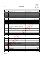
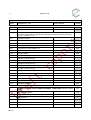
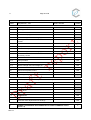
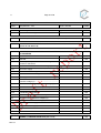
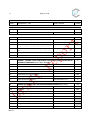
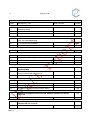
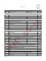
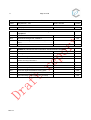
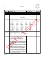
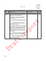
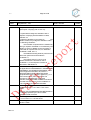
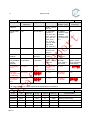
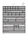
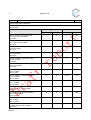
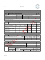
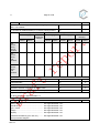
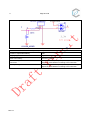
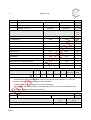
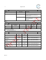
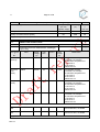
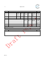
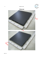
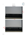
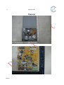


![User Guide [ ] - American Industrial Systems, Inc.](http://vs1.manualzilla.com/store/data/005740554_1-2a4ebbae5daccebd80088e03c7d32b9b-150x150.png)