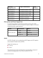
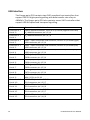
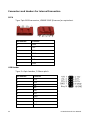
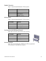
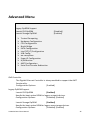
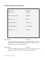
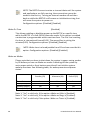
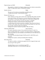
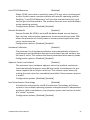
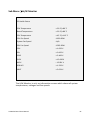
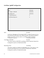
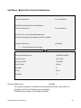
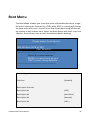
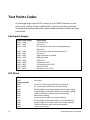
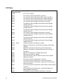
1
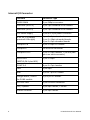
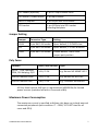
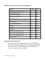
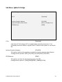
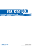
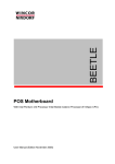
POS Motherboard I1- CPU User Manual We would like to know your opinion on this publication. Please send us a copy of this page if you have any constructive criticism. We would like to thank you in advance for your comments. With kind regards, Your opinion: Wincor Nixdorf International GmbH Documentation R&D SAT 22 Wohlrabedamm 31 D-13629 Berlin E-Mail: [email protected] Order No.: 01750231388A POS Motherboard I1- CPU User Manual Edition February 2013 All brand and product names mentioned in this document are trademarks of their respective owners. Copyright © Wincor Nixdorf International GmbH, 2013 The re production, transmission or use of this document or its contents is not permitted without express authority. Offenders will be liable for damages. All rights, including rights created by patent grant or registration of a utility model or design, are reserved. Delivery subject to availability; technical modifications possible. Contents Overview ....................................................................................... 1 Introduction ....................................................................................... 1 Some Highlights of the I1 Motherboard ............................................ 1 Motherboard Specification ............................................................ 3 Function Blocks of I1 Motherboard ................................................... 3 Motherboard: Mechanical Arrangement........................................... 4 Motherboard PCB Dimension......................................................... 5 External I/O Connector ...................................................................... 5 Internal I/O Connector ....................................................................... 6 Jumper Setting ................................................................................... 7 Poly Fuses .......................................................................................... 7 Maximum Power Consumption ......................................................... 7 Typical Power Consumption .............................................................. 8 Maximum Current Rating for External Peripherals ............................ 9 Supported Power Modes (Sx) ............................................................ 9 Thermal Management ..................................................................... 10 CPU Support ..................................................................................... 10 Memory Support.............................................................................. 10 Graphics Subsystem ......................................................................... 11 System Clock Generator................................................................... 12 Gigabit LAN Interface ....................................................................... 12 Super I/O controller ......................................................................... 12 SATA Interface ................................................................................. 12 CPU, System and Power Supply Fans ............................................... 13 Audio ................................................................................................ 13 USB Interface ................................................................................... 14 Serial Interfaces COM1-6 ................................................................. 15 PS/2 Keyboard Mouse Interface ...................................................... 15 Front Panel Interface ....................................................................... 16 Risercard .......................................................................................... 16 MiniPCIe slot .................................................................................... 16 RMT feature ..................................................................................... 16 Cash Drawer Interface ..................................................................... 16 Intrusion Detect Interface ................................................................ 17 NVRAM ............................................................................................. 17 TPM .................................................................................................. 17 SGPIO Bus Connector ....................................................................... 17 System Beeper ................................................................................. 17 Connector and Pin Assignment..................................................... 18 External Connectors ......................................................................... 18 PS/2 Keyboard-Mouse Connector ............................................... 18 Gigabit LAN Connector ................................................................ 18 USB Connectors ........................................................................... 19 COM1 Connector ......................................................................... 19 COM2* And Other Powered COM Ports Connector .................... 19 DVI-I Connector ........................................................................... 20 DisplayPort Connector ................................................................. 21 Audio Connector .......................................................................... 21 Connectors and Headers For Internal Connection ........................... 22 SATA............................................................................................. 22 USB Header .................................................................................. 22 LED Connector ............................................................................. 23 Fan Connector (with FAN Speed Control).................................... 23 Intrusion Interface ....................................................................... 23 Proprietary Power Connector ...................................................... 24 Mini PCIe (full size) ...................................................................... 25 PCI Riser ....................................................................................... 25 COM3*-6* Connectors ................................................................ 29 USB connector for HUB .................................................................... 30 USB connector for USV..................................................................... 30 USB connector .................................................................................. 30 USB connector .................................................................................. 31 Internal mouse/keyboard connector ............................................... 31 Internal SGPIO connector................................................................. 31 Front panel connector...................................................................... 32 Internal RMT connector ................................................................... 32 Technical Data .............................................................................. 33 Changing the Battery.................................................................... 36 Addendum A: Sleep States ........................................................... 37 UEFI BIOS Setup ........................................................................... 38 Standard UEFI BIOS Version ............................................................. 38 BIOS Menu Bar ................................................................................. 39 Legend Screen .................................................................................. 39 General Help .................................................................................... 40 Scroll Bar .......................................................................................... 40 Sub-Menu ........................................................................................ 41 Info Screen ................................................................................... 42 Main Menu .................................................................................. 44 Advanced Menu ........................................................................... 45 Sub Menu Trusted Computing ..................................................... 46 Sub Menu Hardware Configuration ............................................. 47 Sub Menu CPU Configuration ...................................................... 50 Sub Menu North Bridge ............................................................... 53 Sub Menu SATA Configuration .................................................... 54 Sub Menu TXT(LT) Configuration ................................................. 55 Sub Menu USB Configuration ...................................................... 56 EHCI Hand-off .................................................................................. 56 Sub Menu ME Subsystem ............................................................ 58 ME Subsystem.................................................................................. 58 Sub Menu Super IO Configuration ............................................... 60 Sub Menu H/W Monitor .............................................................. 61 Sub Menu AMT Configuration ..................................................... 62 Sub Menu Serial Port Console Redirection .................................. 63 Boot Menu ................................................................................... 65 Security Menu .................................................................................. 67 Save & Exit Menu ............................................................................. 69 Test Points Codes ......................................................................... 72 Checkpoint Ranges ........................................................................... 72 SEC Phase ......................................................................................... 72 PEI Phase .......................................................................................... 74 PEI Beep Codes ................................................................................ 76 DXE Phase ........................................................................................ 76 DXE Beep Codes ............................................................................... 79 Abbreviations .............................................................................. 80 Overview Introduction This manual describes the features of a Motherboard based on the INTEL Sandy Bridge processor and Q67 chipset in retail form factor. © This I1 Motherboard is designed for the Wincor Nixdorf POS system BEETLE /M-II plus. Some Highlights of the I1 Motherboard nd INTEL Sandy Bridge 2 generation i3, i5, i7 Processor family with integrated Graphic core INTEL 6 series chipset, Q67 Cougar Point PCH Integrated Intel HD and HD 2000 Graphics supporting HDCP, DirectX 10.1 , Full HD 1080p support depending on used processor AMT 7 support (Linux support, Keyboard-Video-Mouse redirection, Firewall tunneling, IPv6 protocol) DVI-I and DisplayPort interface Gigabit LAN onboard ( INTEL Lewisville 82579LM LAN PHY) HDD SATA III interface (2 ports) and HDD SATA II interface (2 ports) Two DDR3 RAM (DIMM) sockets, up to 16GB (2*8GB) / 1066 and 1333MHz, supported size depends on Operating System; max. size 3GB for 32bit OS One riser slot SIO supports PWM fan speed control and 6 COM ports. COM1 is unpowered, COM2 is powered and COM3 to COM6 have the option to be powered I1 Motherboard User Manual 1 MiniPCIe socket (full size) for NVRAM and TPM module support 14 USB ports (3 ports are powered). One of 14 USB ports at miniPCIe card slot Up to 2 cash drawers can be connected via RJ12 connector at the st nd Power Supply. The 1 connector is always populated, the 2 connector is optional TFT- displays without DDC are not supported 2 I1 Motherboard User Manual Motherboard Specification Function Blocks of I1 Motherboard I1 Motherboard User Manual 3 Motherboard: Mechanical Arrangement Intr. MIC LPC (optional) R M T MS/EX KYB/ MSE Battery Mini PCIe USB6 SYS Fan2 USB09 COM1 USB7 USB5 SPKR PWON POW3 SPK USB10_11 CPU Fan1 POW2 LED PWON_PWR/ HDD_LED USB12_13 USB08 POW1 SIO ATXPWR PCI / PCIe Riser USB4/12V BIOS SPI SATA3 SATA2 SATA1 (*) COM6 SATA0 (*) BIOS SPI COM3 (*) USB2/24V COM5 USB3/12V COM2* CPU Socket LGA 1155 COM4 (*) PCH DVI-I CMOS CLEAR Park Position D SOP CMOS CLEAR Displayport PLINK SPKR/DNG SGPIO USB0/1 LAN Stack Channel A DIMM1 Channel B DIMM1 4 I1 Motherboard User Manual Motherboard PCB Dimension The Retail proprietary size is 255mm x 210mm (including I/O shield). External I/O Connector External I/O connectors are arranged as illustrated below: Interface Connector Type COM1 9pin D-sub male COM2 9pin D-sub female Keyboard, Mouse, USB0 6pin Mini Din LAN, USB0,USB1 RJ45 Ethernet + stacked dual USB series A DisplayPort and DVI-I 24 + 5pin DVI-I connector, 20pin Display Port connector AUDIO Speaker Out 3,5 mm female AUDIO Microphone 3,5 mm female Power USB 12V USB2,3 2 pcs 4 + 4pin header Power USB 24V USB4 1 pcs 4 + 4pin header I1 Motherboard User Manual 5 Internal I/O Connector 6 Interface Connector-Type DDR3 DIMM 2 pcs 240pin connector Hard disk (SATA III) 2 pcs 7pin Standard SATA headers Hard disk (SATA II) 2 pcs 7pin Standard SATA headers 12V Power supply 1 pcs ATX 4 pin power connector 3.3V, 5V, 12V supply powered USB supply 1 pcs 2 x 9pin shrouded 1 pcs 2 x 10pin shrouded header 1 pcs 2 x 5pin shrouded header USB port 5-8 5 pcs 1 x 6pin JST header USB port 9 On miniPCIe connector USB port 10-13 2 pcs 2 x 5pin headers, 2.54 mm (two ports on each connector) SGPIO-BUS (BEETLE /M-II plus BOS) 1 pcs 1 x 6pin COM* 3-6 4 pcs 2 x 7pin headers FAN 2 pcs 4pin RMT 1 pc 1x 7 pin JST header Dongle detect, ICHSPK for PLINK module 1 pc 2 pin JST header PCI riser card 1 pcs PCIe x16 connector LED / Speaker 2 pcs 4pin header, 2.54mm Chassis intrusion 1 pcs 3pin header I1 Motherboard User Manual LPC header (optional) 1 pcs 2 x 13pin header 2mm Int. Mouse / Power Button 2 pcs 4pin header Mini PCI-Express 1 pcs 52pin Mini-PCIe header CPU socket 1 pcs 1155pin Intel CPU socket including backplate Jumper Setting Jumper Connector-Type Setting CN24 2 pin RM 2.54 header Open: default, 1-2 CMOS clear JP2 2 pin RM 2.54 header Open: default, 1-2 AMT disabled CN62 2 pin RM 2.54 header Closed: default, CMOS clear jumper park position Poly Fuses Location Hold / Max Current Type 5V for USB, Powered COM, DVI Hotplug, PS/2 1.1A / 2.2A e.g. Bourns MF-MSMF110-2 12V for Powered COM 1.1A / 2.2A e.g. Bourns MF-R110-AP 12V for Powered USB 1.6A / 3.2A e.g. Littlefuse 30R160UPR All Poly fuses have to fulfil the UL requirements (#609501b) for limited power sources (switched off within 5 seconds at 8A). Maximum Power Consumption The maximum current is specified as follows, this does not include external connected peripherals (test condition: I7 – 2600, TAT 100% load for all cores and GPU). I1 Motherboard User Manual 7 Max. Power Consumption Voltage I max P 3.3V 0.56A 1.85 W 5V 0.2A 1W 5VSB 0.2A 1W 12V 11.4A 136 W -12V 0.11A 1.32 W Typical Power Consumption I1 motherboard’s typical power consumption is listed below. Test condition: Motherboard rev.: B, no peripherals, keyboard, mouse, USB devices, COM port not connected, Ethernet link and memory configuration as mentioned below, Windows 7- 64Bit idle. Voltage 3.3V 5V 5VSB (S0) 12V Condition S0 No Ethernet link S0 100MBit S0 1GB S3 (no WOL) S3 (WOL 10 Mbit) S5 (no WOL) S5 (WOL 10 Mbit) 2GB 1* ELIXIR/1333 4GB 2* ELIXIR/1333 Intel Max Power -12V 8 I 0.76A 0.23A 0.18A 0.18A 0.20A 0.15A 0.19A 0.11A 0.13A 1A RMS max 0.61 RMS mean 1.2A RMS max 0.60 RMS mean 10.75A RMS max 10.05A RMS mean 0.105A P 2.5 W 1.15 W 0.9 W 0.9 W 1.02 W 0.75 W 0.96 W 0.55 W 0.65 W 12 W 7.34 W 14.4 W 7.22 W 129 W 120.6 W 1.26 W I1 Motherboard User Manual Maximum Current Rating for External Peripherals Interface Voltage I max Powered COM, total current (COM 2*-6*) 5V 1A Powered COM single port 5V 0.3A Powered COM single port 12V 0.6A Powered COM, total current (for COM 2*, 3*, 4*) 12V 0.9A Powered COM, total current (for COM 5*, 6*) 12V 0.9A USB, single port 5V 0.5A USB, all ports, total current 5V 3.5A Keyboard 5V 0.5A DVI, VGA 5V 0.1A Display Port 3,3V 0.1A Powered USB, single port PUSB1 12V 3A Powered USB, single port PUSB2 12V 1,5A Powered USB, single port PUSB3 24V 3A PCI or PCIe Card all 10W Supported Power Modes (Sx) The I1 Motherboard supports power states S0, S3, S4 and S5. Wake up events from sleep states are supported by USB ports on LAN / USB doublestack connector 12V poweredUSB ports, internal USB HUB COM1 ring indicator, internal CMOS clock, PS2 Keyboard or mouse and Ethernet. The Power management supports ACPI 2.0. I1 Motherboard User Manual 9 Thermal Management The I1 Motherboard supports 2 FAN connectors with 4pin fan type. The 3rd FAN, located in the power supply, is connected through the power supply connector. CPU Support Processor nD 2 Gen. Sandy Bridge I3-2120 nD 2 Gen. Sandy Bridge I5-2400 nD 2 Gen. Sandy Bridge I7-2600 Pentium G850 Celeron G540 Clock Speed 3.3GHz Foot print LGA1155 Internal Graphic frequency (Turbo) /MHz HD 2000 / 850 (1.100) Max TDP 65W AMT 7 3.1GHz LGA1155 HD 2000 / 850 (1.100) 95W AMT 7 3.4GHz LGA1155 HD 2000 / 850 (1.350) 95W Standard manageability 2.9GHz LGA1155 65W Standard manageability 2.5GHz LGA1155 HD / 850 (1.100) HD / 850 (1.000) AMT Standard manageability 65W Memory Support The motherboard has 2 DIMM sockets supporting double channel, unbuffered, no ECC DDR3 SDRAM. Supported Memory size is up to 8GB per channel. Supports total memory size of 1 GB, 2 GB, 4 GB, 8 GB and 16 GB max The motherboard supports the following memory features: 1066 and 1333MHz, unbuffered DDR3 SDRAM DIMM Non-ECC 1.5V voltage rating BIOS automatically detects memory type, size, and speed 10 I1 Motherboard User Manual Graphics Subsystem Graphics support through the internal graphics accelerator of the Sandy Bridge processor providing dual independent displays. Main features are: INTEL HD and HD2000 on embedded processors. Directx* 10.1 The PCH Analogue VGA Port uses an integrated 340.4 MHz RAMDAC that can directly drive a standard progressive scan analogue monitor up to a resolution of 2048 x 1536 pixels with 32-bit colour at 75 Hz. HD3000 is not available on embedded processors. Video clock frequency is 850 MHz to 1350 MHz (with Turbo boost) depending on processor (for details please see chapter “CPU support”). Max. DISPLAY Resolution: Analogue Display VGA: 2048 x 1536 pixels with 32-bit colour at 75 Hz. Digital Display DisplayPort: DVI-I: VIDEO out: I1 Motherboard User Manual 2560 x 1600 at 60 Hz 1920 x 1200 at 60 Hz using DVI (with reduced blanking). DVI and VGA on DVI-I connector DisplayPort interface PLink on separate PLINK-DP-MODULE connected via DisplayPort cable. 11 Signal Voltage level R,G,B 0.7VP-P @75OHM HSYNC, VSYNC 2.5V DDC Channel Externally buffered to 5.0V System Clock Generator The PCH offers Full Integrated Clock Mode (FICM). This feature leads to reduced power consumption because an external clock synthesizer is not necessary. Gigabit LAN Interface A Gigabit LAN interface is provided by the PCI-e based Ethernet Controller INTEL 82579LM which supports AMT 7. Super I/O controller Super I/O controller IT8783 from ITE provides the following functions: Six 16C550 UARTs PS/2 keyboard/ mouse controller Three automatic fan speed controllers Three tachometer inputs Hardware monitor SATA Interface The I1 Motherboard has two integrated SATAIII (6GB/s) and two SATAII (3GB/s) host controllers that support independent DMA operation. 12 I1 Motherboard User Manual SATA Port Cougar Point PCH Usage on Motherboard SATA Controller Port #0 SATA III On-board connector SATA0 1 Port #1 SATA III On-board connector SATA1 1 Port #2 SATA II On-board connector SATA2 1 Port #3 SATA II On-board connector SATA3 1 Port #4 SATA II Routed on Test points 2 Port #5 SATA II Routed on Test points 2 CPU, System and Power Supply Fans I1 motherboard supports automatic fan speed control by pulse width modulation (PWM). The 3rd fan, located in the power supply, is connected through the power supply connector. System BEETLE /M-II plus FAN Connector Used as C_FAN1 CPU fan C_FAN2 System fan CN33 pin 16 Power supply FAN RPM Audio An INTEL HD Audio Link is provided by the Q67 Cougar point PCH together with a Realtek HD Audio Codec (ALC262). Supported interfaces are: Line-out Mic-in The onboard stereo audio amplifier delivers typically 2W per channel of continuous average power to an 8 Ohm load with 10% THD. I1 Motherboard User Manual 13 USB Interface The Cougar point PCH contains two EHCI compliant host controllers that support USB 2.0 high speed signalling with data transfer rate of up to 480Mb/s. The Cougar point PCH also contains seven UHCI controllers that support USB full speed and low speed signalling. EHCI Controller #: 1 Port # :0 Controller #: 1 Port # :1 Controller #: 1 Port # :2 Controller #: 1 Port # :3 Controller #: 1 Port # :4 Controller #: 1 Port # :5 Controller #: 1 Port # :6 Controller #: 1 Port # :7 Controller #: 2 Port # :8 Controller #: 2 Port # :9 Controller #: 2 Port # :10 Controller #: 2 Port # :11 Controller #: 2 Port # :12 Controller #: 2 Port # :13 14 Connection on Motherboard 2 ports stacked connector, series A in I/O shield (together with LAN) U_LANM1A connector pin 1,2,3,4 U_LANM1A connector pin 5,6,7,8 USB 3 –1 port 12V power USB connector, series A in I/O shield (right ) USB1 connector pin 1,2,3,4 USB 4 –1 port 12V power USB connector, series A in I/O shield (mid) USB2 connector pin 1,2,3,4 USB 5-1 port 24V power USB connector, series A in I/O shield (mid) USB2 connector pin 1,2,3,4 USB 5 (yellow) JST 6 pin connector CN28 connector pin 1,2,3,4 USB 6 (red) JST 6 pin connector CN29 connector pin 1,2,3,4 USB 7 (green) JST 6 pin connector CN30 connector pin 1,2,3,4 USB 8 (green) JST 6 pin connector CN75 connector pin 1,2,3,4 USB 9 Mini PCIe full size connector MINI_PCIE1 pin 36,38 USB 10 2*5 pin header RM2.54 FPU3 connector pin 1,3,5,7 USB 11 2*5 pin header RM2.54 FPU3 connector pin 2,4,6,8 USB 12 2*5 pin header RM2.54 FPU4 connector pin 1,3,5,7 USB 13 2*5 pin header RM2.54 FPU4 connector pin 2,4,6,8 I1 Motherboard User Manual Serial Interfaces COM1-6 The I1 Motherboard provides six serial ports. COM1 is a standard serial interface. All RS-232 signals are available on the DSUB-9 pin male connector including the modem signals RI and DCD. COM2* is a powered COM. The following cable assemblies (used also on G41 motherboard) for powered COM and standard RS232 functionality are available: Cable for COM 5*-6* mounted in housing (female, powered): 1750209149 9DSUB-FEMALE_COM_Kabel_195mm Cable for COM 5-6 mounted in housing (male, non-powered standard): 1750209150 9DSUB-MALE_COM_Kabel_195mm Cable for COM 3*-4* mounted in I/O shield(female, powered): 5789000416 COM7 VARIABLE STVB-FEMALE Cable for COM 3-4 mounted in I/O shield (male, non-powered): 6161800416 COM7 VARIABLE STVB-MALE With the standard cable assembly all RS232 signals are available including the modem signals RI and DCD. With the powered COM cable assembly, the I/O assignments of the powered serial ports (COM3* to COM6*) deviate from the standard, as it is equipped with system voltage of + 5V and + 12V instead of the signals RI and DCD. These serial ports are routed to 2 x 7pin headers (2.0 mm shrouded) and via cables to DSUB-9 pin male (standard) or female (powered) connectors. All serial ports comply with RS-232 signal voltage level. PS/2 Keyboard Mouse Interface The keyboard controller is part of the Super I/O chip. The PS/2 keyboard/mouse interface is available on a Mini DIN connector. Type: 6pin Mini Din (Tyco 5749180-1) Note: This type is equipped with a locking mechanism. An internal connector provides an additional mouse interface. I1 Motherboard User Manual 15 Front Panel Interface The motherboard has a front panel interface, which supports the following features: Power ON/OFF button and Reset button Status LED, showing Active S0- state (Green), Standby S3 (flashing green, this feature is only available at front panel header FP1) ,S4,S5state(orange), HDD activity LED (Amber, flashing) also used as BIOS activity LED System beeper Risercard The I1-RISER-PCIe4x-PCI card (01750231212) supports one PCIe x4 and one PCI card. MiniPCIe slot I1 Motherboard supports a mini PCIe slot. This interface contains extra LPC bus signals for direct support of BIOS post code cards (I/O 80h), TPM modules, NVRAM modules, wireless LAN and others. Half size modules can be plugged. RMT feature I1 Motherboard supports the optional RMT module (Kit order number: 01750182128) on connector J2. This interface is used to remote power on the motherboard from a connected Wincor Nixdorf Monitor BA82/BA83. Furthermore the PC speaker signal is routed to the monitor using this interface. Cash Drawer Interface The I1 Motherboard supports 2 cash drawer interfaces. The connector for cash drawer control and feedback is part of the power supply connector. 16 I1 Motherboard User Manual st The 1 cash drawer is connected via RJ12 connector located at Power Supnd ply. Connection for 2 cash drawer is optional (an additional interface card is necessary). Reading of I/O address 310h gets back status of cash drawer and power button. 1 indicates an open cash drawer. 0 indicates a closed or not connected cash drawer. 7 6 5 4 3 2 1 0 CD2 CD1 PB x x x x x Writing 1 to address 310h bit 6 or 7 initiate a 500ms active low signal on the cash drawer output 1 or 2. Writing 1 to both bits at the same time is not supported by hardware. In this case both outputs stay inactive. Intrusion Detect Interface I1 Motherboard supports an intrusion detect interface on a 3pin shrouded header. NVRAM NVRAM is supported by the NVRAM-MiniPCIe-v2 module (01750244359). TPM The I1 Motherboard is prepared for Infineon TPM IC. The TPM-MODULEminiPCIe-v2 (01750244361) is supported. SGPIO Bus Connector BEETLE BOS functions are supported via SGPIO bus connector. System Beeper The I1 Motherboard supports a speaker interface connector. I1 Motherboard User Manual 17 Connector and Pin Assignment External Connectors PS/2 Keyboard-Mouse Connector Type: Mini-DIN Female Pin Number Function 1 KB Data 2 MS Data 3 GND 4 KB+5V 5 KB Clock 6 MS Clock 7, 8, 9 Shield GND Gigabit LAN Connector Type: RJ45 connector. (Stacked LAN + USB connector) Pin number 10 11 12 13 14 15 16 17 18 Function Bi-directional Pair 0+ Bi-directional Pair 0Bi-directional Pair 1+ Bi-directional Pair 1Bi-directional Pair 2+ Bi-directional Pair 2Bi-directional Pair 3+ Bi-directional Pair 3- I1 Motherboard User Manual USB Connectors Type: Stacked USB Type A connector, Male (Stacked LAN + 2* USB A Connector) Pin Number Function 1 Fused +5V 2 USB D- 3 USB D+ 4 GND COM1 Connector Type: DSUB- 9pin, male, DSUB- 9 Male Pin number Function 1 DCD - Data Carrier Detect 2 RXD - Serial Data In 3 TXD - Serial Data Out 4 DTR - Data Terminal Ready 5 GND 6 DSR - Data Set Ready 7 RTS - Request To Send 8 CTS - Clear to Send 9 RI - Ring Indicator COM2* And Other Powered COM Ports Connector Type: DSUB-9 pin, female Pin number Function 1 +12V 2 RXD - Serial Data In 3 TXD - Serial Data Out 4 DTR - Data Terminal Ready 5 GND 6 DSR - Data Set Ready I1 Motherboard User Manual 19 Pin number Function 7 RTS - Request To Send 8 CTS - Clear to Send 9 +5V DVI-I Connector Type: 24+5 pin DVI-I connector 20 Pin number Function C1 Red C2 Green C3 Blue C4 HSYNC C5 GND 1 TMDS Data 2- 2 TMDS Data 2+ 3 TMDS Data 2/4 shield 4, 5, 12, 13, 20, 21 n.c. 6 DDC SCL 7 DDC SDA 8 VSYNC 9 TMDS Data 1- 10 TMDS Data 1+ 11 TMDS Data1/3 shield 14 VCC 15 GND 16 HPD 17 TMDS Data 0- 18 TMDS Data 0+ 19 TMDS Data0/5 shield 22 TMDS CLK shield 23 TMDS CLK1+ 24 TMDS CLK1- I1 Motherboard User Manual DisplayPort Connector Type: CompuPack DP202001LS6-A2-RS1 or equivalent Pin Number Function 1 LANE0+ 2,5,8,11,16 GND 3 LANE0- 4 LANE1+ 6 LANE1- 7 LANE2+ 9 LANE2- 10 LANE3+ 12 LANE3- 13 CONFIG1 (Dongle detect) 14 CONFIG2 (GND) 15 AUXCH+ 17 AUXCH- 18 Hotplug detect 19 PWR_RTN (GND) 20 DP_PWR_3V3 21,22,23,24 Case GND Audio Connector Type: Audio Jack Connector Function SD3 Line/Speaker out SD4 Microphone In I1 Motherboard User Manual 21 Connectors and Headers For Internal Connection SATA Type: 7pin SATA connector, LD180F-S16P (Foxconn) or equivalent. Pin number Function 1 GND 2 TXP 3 TXN 4 GND 5 RXN 6 RXP 7 GND USB Header Type: 2 x 5pin headers, 2.54mm pitch. 22 Pin number Function 1 +5V 2 +5V 3 D0- 4 D1- 5 D0+ 6 7 D1+ GND 8 GND 9 Key 10 GND I1 Motherboard User Manual Speaker Connector Type: 1 x 4pin shrouded header, 2.54 mm pitch Pin number Function 1 Speaker - 2 GND 3 Reset switch + 4 Speaker + (VCC) LED Connector Type: 1 x 4pin shrouded header, 2.54 mm pitch. Pin Number Function 1 LED common 2 n.c. 3 HD / BIOS LED 4 Power LED Fan Connector (with FAN Speed Control) Type: 4pin connector with Friction Lock, vertical. Pin Number Function 1 GND 2 +12V 3 FAN RPM 4 FAN PWM Intrusion Interface Type: 3pin shrouded header, B3B-PH-K-S (JST) or equivalent. This connector is available as an option. I1 Motherboard User Manual 23 Pin number Function 1 GND 2 Intrusion input 3 n.c. Proprietary Power Connector Type: 2 x 9pin shrouded header, RM2.54 Pin Number Function 1, 2, 3, 4 GND 5 Coding pin 6, 7, 8, 9, 10 +3.3V 11 KLA2N 12 KLA1N 13 KLE2N 14 KLE1N 15 FANCON_PSU 16 FAN_RPM_PSU 17, 18 +5V Type: 2 x 5pin shrouded header, RM2.54 24 Pin Number Function 1 5VSB 2 GND 3, 4, 5 +24V 6, 7, 8 GND 9, 10 +12V I1 Motherboard User Manual 2 x 10pin shrouded header, RM2.54 Pin Number Function 1 Power ok 3, 4 + 12V 5, 6, 15, 16, 17 GND 8 - 12V 9 Power ok 10 Coding pin 11, 13, 14 + 5V 12 5VSB 18 PSON 20 AKLOW 2, 7, 19 n.c. 2 x 2pin Standard ATX 12V connector Pin Number Function 1, 2 GND 3, 4 + 12V Mini PCIe (full size) Full- size modules are supported. PCI Riser The riser slot shall support riser cards with one PCIE X4 and one PCI slot and is prepared to support cards with two PCI slots. I1 Motherboard User Manual 25 26 Pin Number Function Pin Number Function B1 PCI_RESET# A1 GND B2 GND A2 RSEVD6 B3 PREQ-1 A3 GND B4 PIRQ-D A4 IDSEL0 B5 +5V A5 GND B6 GND A6 IDSEL1 B7 PGNT-1 A7 GND B8 GND A8 RSEVD3 B9 LOCK# A9 GND B10 GND A10 PCICLK0 B11 PIRQ-A A11 GND B12 ADDRESS30 A12 GND B13 ADDRESS28 A13 PCICLK1 B14 +5V A14 GND B15 ADDRESS26 A15 PREQ-2 B16 +5V A16 GND B17 ADDRESS24 A17 WOL# B18 ADDRESS23 A18 PIRQ-C B19 PRSNT2 A19 GND B20 ADDRESS22 A20 PGNT-2 B21 +5V A21 GND B22 ADDRESS19 A22 PIRQ-B B23 +5V A23 GND B24 ADDRESS17 A24 ADDRESS31 B25 GND A25 +3V3 B26 C-BE2 A26 ADDRESS29 B27 GND A27 +3V3 I1 Motherboard User Manual Pin Number Function Pin Number Function B28 TRDY# A28 ADDRESS27 B29 GND A29 +3V3 B30 PERR# A30 ADDRESS25 B31 GND A31 +3V3 B32 DEVSEL# A32 C-BE3 B33 +5V A33 ADDRESS21 B34 PAR A34 ADDRESS20 B35 GND A35 FRAME# B36 ADDRESS15 A36 WAKE# B37 GND A37 IRDY# B38 ADDRESS13 A38 PLTRST# B39 +5V A39 STOP# B40 ADDRESS11 A40 SMB_data B41 GND A41 SERR# B42 ADDRESS09 A42 SMB_clock B43 GND A43 +3V3 B44 C-BE0 A44 GND B45 +5V A45 ADDRESS18 B46 ADDRESS06 A46 C-BE1 B47 +5V A47 ADDRESS16 B48 ADDRESS04 A48 +3V3 B49 +3V3SB A49 ADDRESS14 B50 +12V A50 ADDRESS12 B51 ADDRESS02 A51 ADDRESS10 B52 +5V A52 +3V3 B53 ADDRESS00 A53 ADDRESS08 B54 PRSNT1 A54 +3V3 I1 Motherboard User Manual 27 28 Pin Number Function Pin Number Function B55 +5VSB A55 ADDRESS07 B56 +5VSB A56 +3V3 B57 -12V A57 ADDRESS05 B58 -12V A58 +3V3 B59 GND A59 ADDRESS03 B60 PETN4 A60 +3V3 B61 PETP4 A61 ADDRESS01 B62 GND A62 +3V3 B63 GND A63 +12V B64 PERP4 A64 +12V B65 PERN4 A65 +12V B66 GND A66 +12V B67 GND A67 GND B68 PCIECLK2N A68 PETP3 B69 PCIECLK2P A69 PETN3 B70 GND A70 GND B71 GND A71 GND B72 PCIECLK1N A72 PERP3 B73 PCIECLK1P A73 PERN3 B74 GND A74 GND B75 GND A75 GND B76 PETN1 A76 PERP2 B77 PETP1 A77 PERN2 B78 GND A78 GND B79 GND A79 GND B80 PERP1 A80 PETN2 I1 Motherboard User Manual Pin Number Function Pin Number Function B81 PERN1 A81 PETP2 B82 GND A82 GND COM3*-6* Connectors Connector type: 2x7 pin header JST B14B-PHDSS or similar Pin Number Function 1 +5V 2 GND 3 DCD - Data Carrier Detect 4 GND 5 CTS - Clear to Send 6 DTR - Data Terminal Ready 7 RTS - Request To Send 8 TXD – Serial Data Out 9 DSR - Data Set Ready 10 RXD - Serial Data In 11 RI - Ring Indicator 12 GND 13 +12V 14 GND I1 Motherboard User Manual 29 USB connector for HUB Type: CN75, 6 pin shrouded header, B6B-PH-K-M (JST, green) or equivalent. Pin Number Function 1 5V_DUAL_USB 2 USBP8N 3 USBP8P 4 GND 5 GND 6 USB_OC4_R_N USB connector for USV Type: CN28, 6 pin shrouded header, B6B-PH-K-Y (JST, yellow) or equivalent. Pin Number Function 1 VCC 2 USBP5N 3 USBP5P 4 GND 5 GND 6 OC5 (USB_OC3_R_N) USB connector Type: CN29, 6 pin shrouded header, B6B-PH-K-R (JST, red) or equivalent. 30 Pin Number Function 1 VCC 2 USBP6N 3 USBP6P 4 GND 5 GND 6 OC5 (USB_OC3_R_N) I1 Motherboard User Manual USB connector Type: CN30, 6 pin shrouded header, B6B-PH-K-M (JST, green) or equivalent. Pin Number Function 1 VCC 2 USBP7N 3 USBP7P 4 GND 5 GND 6 OC5 (USB_OC3_R_N) Internal mouse/keyboard connector Type: 4 pin shrouded header, B4B-PH-K-S (JST) or equivalent. Pin Number Function 1 GND 2 MS_CLK 3 MS_DATA 4 KBMSVCC Internal SGPIO connector Type: 6 pin shrouded header, B6B-PH-K-S (JST) or equivalent. Pin Number Function 1 VCC 2 GP22 3 GP38 4 GNDGP39 5 PLTRST_N 6 GND I1 Motherboard User Manual 31 Front panel connector Type: FP1, 2x6 pin header, 2.54mm pitch. Pin Number Function 1 PWBTIN_N 2 FP_RST_N 3 GND 4 GND 5 PLED+ 6 SPK 7 PLED- 8 Coding pin 9 HDD_LED+ 10 GND 11 HDD_LED- 12 SPK-PW Internal RMT connector Type: J2, 7 pin shrouded header, B7B-PH-K-S (JST) or equivalent. 32 Pin Number Function 1 GND 2 PWBTNIN_N 3 n.c. 4 n.c. 5 n.c. 6 ICHSPK 7 5VSB I1 Motherboard User Manual Technical Data nd Microprocessor INTEL Sandy Bridge 2 generation i3, i5, i7 Processor family Supported Systems BEETLE /M-II plus Architecture PC-AT compatible and POS - specific functional units Chipset Q67 Cougar point PCH, supporting SATA (II and III) controller, USB UHCI and EHCI controller, Interrupt controller, DMA controller, LPC interface, RTC, SMBUS host interface PCI, PCIexpress x1 and x4, Intel High Definition Audio interface, SPI, Intel Anti-Theft Technology: INTEL VT/TXT support, INTEL RST, vPro and RAID support, Intel Turbo Boost Technology Super I/O IT8783, supporting 6 UARTS, PS/2 Keyboard and Mouse interface, automatic fan speed controller, Hardware monitor, chassis intrusion detection, power button disable function Ethernet PHY PCI-e based INTEL 82579LM Lewisville (10/100/1000MBit), PXE Wake On Feature Wake On LAN/WLAN, Wake On Time, Wake On USB1 and USB2 (USB/ LAN stack), Wake On Keyboard, Wake On Modem (standard via RI COM1), Wake On RMT (only with optional RMT module) Sound Controller I1 Motherboard User Manual Audio Codec and amplifier TEA2025B providing 2W per channel @ 8ohm, 10% THD Stereo Speaker Out and Mic-in, connectors in I/O shield, common GND on speaker out 33 Cash Drawer Output Input Supporting up to 2 cash drawers, Onboard CPLD, support for up to two cash drawers Open / closed state of two cash drawer ports can be detected NVRAM, TPM Optional mini PCIe module supported Main Memory Max. 16 GB (2 * 8GB) , size depends on Operating System; max size 3GB for winXP (32 bit OS), non-ECC running at 1066/1333 MHz BIOS SPI Flash, 16MB, AMI BIOS with customization for BEETLE Systems, PnP 1.1, ACPI, DMI-support Keyboard PS/2 connection onboard in I/O shield, supporting Y-cable for Mouse support 4 pin JST connector for additional internal PS/2 connection (mouse only) Serial Interfaces COM1 onboard in I/O shield, DSUB-9 pin male connector, COM2 onboard in I/O shield, DSUB-9 pin female connector powered COM, COM3 to COM6 onboard 2x7 pin headers supporting powered COM USB USB2.0, 14 ports. USB port 0, 1: 2 ports stacked connector, series A in I/O shield (together with LAN) USB port 2, 3: 2 ports 12V power USB connector, series A in I/O shield USB port 4: 1 port 24V power USB connector series A in I/O shield USB port 5 (yellow), USB port 6 (red), USB port 7 (white), USB port 8 (green): 4 ports: 1x6pin internal coloured JST PHR connector 34 I1 Motherboard User Manual USB port 9- 1 port: Connected to mini PCIe card slot USB ports 10, 11, 12, and 13: Four ports on two internal 2x5 pin headers. Status LED Two front panel LEDs: one Power LED (yellow/green), flashing in S3 and one shared orange LED for HDD and BIOS activity. Onboard LEDs 3 LEDs: PWROK (green), PROCHOT (yellow) and WLAN activity (yellow). HDD 2 x SATA II interface (3.0 Gbit/s), 2 x SATA III interface (6.0 Gbit/s). Riser Card PCI Bus (32 Bit interface, 33MHz) PCI Express 1.0a, PCIe x4 Video out Dual independent display INTEL HD2000 internal graphic available on embedded processors. Battery for RTC and Super-I/O, Type: CR2032, 220mAh. Fuses Poly switches for +5V of powered COM, PS/2 and DVI Power, all USB, +12V and 24V of powered USB, +12V powered COM. Board Dimension 255mm x 210mm I1 Motherboard User Manual 35 Changing the Battery The BEETLE POS systems are equipped with a lithium battery on the motherboard (see also page 4) to ensure data retention, the time and the setup parameters. The battery should be changed approximately every five years. When inserting the new battery, make sure the polarity is correct. This is marked in the socket. Incorrect replacement of the battery may lead to the danger of explosion. The battery is located in a socket on the Motherboard. To gain access to the battery, proceed as described in the according chapters of your BEETLE User Manual. See: http://www.wincor-nixdorf.com/internet/site_EN//EN/Support/ Downloads/POSLotterySystems/Manuals/manuals_node.html The lithium battery must be replaced only by identical batteries or types recommended by Wincor Nixdorf International. You can return the used batteries to your Wincor Nixdorf International sales outlet. Batteries containing harmful substances are marked accordingly. The chemical denotations are as follows: CD = Cadmium; Pb = Lead, Li = Lithium. This symbol on a battery tells you that batteries containing harmful substances must not be disposed of as household waste. Follow the country specific laws and regulations. Within the European Union you are legally bound to return these batteries to the service organization where you purchased the new battery. The setup parameters must be reset each time the battery has been changed. 36 I1 Motherboard User Manual Addendum A: Sleep States S0 Normal operation (“On”) S3 Suspend to RAM / “Stand By” S4 Suspend to Disk / “Hibernation” S5 Soft Off I1 Motherboard User Manual 37 UEFI BIOS Setup The main board I1.0-Q67-STD comes with an AMI UEFI BIOS chip that contains the ROM Setup information of your system. This chip serves as an interface between the processor and the rest of the main boards components. This section explains the information contained in the Setup program and tells you how to modify the settings according to your system configuration. Even if you are not prompted to use the Setup program, you might want to change the configuration of your system in the future. For example, you may want to enable the Security Password Feature or make changes to the power management settings. It will then be necessary to reconfigure your system using the BIOS Setup program so that the system can recognize these changes and record them in the NVRAM. All setup data is stored in a non-volatile memory (NVRAM). When you remove the battery, all parameters will be lost. Standard UEFI BIOS Version The UEFI BIOS ROM of the system holds the Setup utility. When you turn on the system, it will provide you with the opportunity to run this program. This appears during the Power-On Self Test (POST). Press <F2> to call the Set-up utility. If you missed to press this key, POST will continue with its test routines, thus preventing you from calling Setup. If you still need to call Setup, reset the system by pressing <Ctrl> + <Alt> + <Del>. You can also restart by turning the system off and then on again. But do so only if the first method failed. If you like to change the boot order only once, you can press the <F10> key during the POST is running. At the end you will see a Pop-Up window with all the devices the system has found. With the keys <UP> and <DOWN> you select the boot device. The Setup program has been designed to make operations as easy as possible. It is a menu-driven program, so that you can scroll through the various sub-menus and make your selections among the predetermined choices. 38 I1 Motherboard User Manual When you start Setup, the main program screen will appear. Read more about the Setup entries on the following pages. As the UEFI BIOS software is constantly being updated, the following UEFI BIOS screens and descriptions are for reference purposes only and may not reflect your UEFI BIOS screens exactly. BIOS Menu Bar The top of the screen has a menu bar with the following sections: Info Use this menu for information only Main Use this menu to make changes to the basic system configuration. Advanced Use this menu to enable and make changes to the advanced features. Boot Use this menu to configure the default system device used to locate and load the Operating System. Security Use this menu to enable a supervisor or user password and Intrusion Detection. Save & Exit Use this menu to exit the current menu or specify how to exit the Setup program. To access the menu bar items, press the right or left arrow key on the keyboard until the desired item is highlighted. Legend Screen The right frame displays the key legend. The keys in the legend frame allow you to navigate through the various setup menus. The following table lists the keys found in the legend with their corrsponding alternates and functions. I1 Motherboard User Manual 39 Navigation Key(s) Description of Functions ← or → (keypad arrows) Select the menu item to the left or right. ↑ or ↓ (keypad arrows) Moves the highlight up or down between fields. + (plus key) - (minus key) Change field contents. <Tab> Jumps from one field to the next. <F1> Opens a general Help Screen with extended informations. <F4> Saves changes and exits Setup. <Esc> Opens a windows to select between exit and return to Setup General Help In addition to the Item Specific Help window, the UEFI BIOS setup program provides a General Help screen. This screen can be called from any menu by pressing <F1>. The General Help screen lists the legend keys with their corresponding alternates and functions. Scroll Bar When a scroll bar appears to the right of a help window it indicates that there is more information displayed that will not fit into the window. Use <PgUp> and <PgDn> or the up and down keys to scroll through the entire help document. Press <Home> to display the first page, press <End> to reach the last page. To exit the help window, press the <Enter> or <Esc> key. 40 I1 Motherboard User Manual Sub-Menu Note that a right pointer symbol “” appears left of certain fields. This pointer indicates that a sub-menu can be launched from this field. A sub-menu contains additional options for a field parameter. To call a sub-menu move the highlight to the field and press <Enter>. The sub-menu will then appear immediately. Use the legend keys to enter values and move from field to field within a sub-menu just as you would do within a menu. Use the <Esc> key to return to the main menu. Take your time to familiarize yourself with each of the legend keys and their corresponding functions. Practice navigating through the various menus and sub-menus. If you accidentally make unwanted changes to any of the fields, use the set default hot key <F3>. While moving around through the Setup program, note that explanations appear in the Item Specific Help window located at the right side of each menu. This window displays the help text for the currently highlighted field. I1 Motherboard User Manual 41 Info Screen When the Setup program is accessed, the following info screen appears: Wincor Nixdorf Info Page Product Name: I1.0-Q67-STD Bios Version xx/yy 09/28/2012 Ethernet MAC-Address AC-DC-FA-DE-BE-EF d716af80-6f0a-1018-8789-fbd248a1242f System: --------------------------- --- --------------###----------------------------------------Mainboard: --------------------------- --- --------------###----------------------------------------Power Supply: --------------------------- --- --------------###----------------------------------------- This screen is for information only. Nothing can be changed herein. All information is intended to facilitate the support of your system. Product Name This text is fixed for your mainboard with standard UEFI BIOS. This board is also called “I1.0-Q67-STD”. 42 I1 Motherboard User Manual BIOS Version The UEFI BIOS version is displayed in the WN release format xx/yy The UEFI BIOS Date is displayed the date of release in international format. Ethernet MAC Address The Ethernet MAC-Address of the onboard LAN Controller is displayed at this line if this device is [Enabled]. UUID Info A UUID is an identifier standard used in software construction, standardized by the Open Software Foundation. The intent of UUIDs is to enable distributed systems to uniquely identify information without significant central coordination. System, Main board, Power Supply The default placeholders may be replaced by specific data from factory, describing configuration, serial number etc. for each device. I1 Motherboard User Manual 43 Main Menu BIOS Information Memory Information Total Memory 2048 MB (DDR3 1067) System Date System Time [FR 09/29/2012] [23:23:23] Access Level Administrator System Date [XX/XX/XXXX] Sets your system to the date that you specify (usually the current date). The format is month, day, year. Valid values for month, day and year are: Month: (1 to 12), Day (1 to 31), Year: (up to 2079). System Time [XX: XX: XX] Sets your system to the time that you specify (usually the current time). The format is hour, minute, second. Valid values for hour, minute, and second are: Hour: (00 to 23), Minute: (00 to 59), Second: (00 to 59). Press <Enter> to terminate every entry value and reach the next position. On the upper right frame find the keys listed to modify the values. 44 I1 Motherboard User Manual Advanced Menu GbE Controller Enabled Legacy OpROM Support Launch PXE OpROM Launch Storage OpROM [Disabled] [Enabled] Trusted Computing Hardware Configuration CPU Configuration North Bridge SATA Configuration Intel TXT(LT) Configuration USB Config. ME Subsystem Super IO Configuration H/W Monitor AMT Configuration Serial Port Console Redirection GbE Controller The Gigabit Ethernet Controller is always enabled to support the AMT functionality. Configuration Options: [Enabled] Legacy OpROM Support Launch PXE OpROM [Enabled] Handle the boot option ROM for legacy network devices. Configuration Options: [Disabled] [Enabled] Launch Storage OpROM [Enabled] Handle the boot option ROM for legacy mass storage devices. Configuration Options: [Disabled] [Enabled] I1 Motherboard User Manual 45 Sub Menu Trusted Computing TPM Configuration TPM Support TPM State Pending TPM Operation [Disabled] [Disabled] [None] Current TPM Status Information TPM Enabled Status TPM Active Status TPM Owner Status [Disabled] [Deactivated] [UnOwned] TPM Support [Disable] This option enable or disable the Trusted Platform Module. After change this option the system will reboot automated. If the security device is disable the OS will not show this device in device list. TPM State [Disabled] This option change the actual state of the security module. Select the TPM operation after the next automated reboot of the system. Pending TPM Operation [None] [None]: The TPM state will be untouched. [Enable Take Ownership]: This option will enable to take the ownership. [Disable Take Ownership]: This option will disable to take the ownership. [TPM Clear]: WARNING! Clearing erases information stored on the TPM. You will lose all created keys and access to data encrypted by these keys. After clearing the TPM, it will get the status “deactivated” and not owned. 46 I1 Motherboard User Manual Sub Menu Hardware Configuration Wake On LAN [Enabled] Wake On Ring [Disabled] Wake On Time [Disabled] Display Output to COM3 [Disabled] Speaker Volume [High] Restore AC Power Loss [Power Off] Onboard COM5/COM6 [Auto Disabled] BootOrder Menu [Enabled] Wake On LAN [Disabled] This allows enabling or disabling power up the BEETLE when the LAN controller receives a call while the BEETLE is in Soft-Off or Hibernate mode. Configuration options: [Disabled] [Enabled]. Wake On Ring [Disabled] This allows enabling or disabling power up the BEETLE when the modem receives a call while the BEETLE is in Soft-Off or Hibernate mode. I1 Motherboard User Manual 47 NOTE: The BEETLE cannot receive or transmit data until the system and applications are fully running, thus connection cannot be made on the first try. Turning an external modem off and then back on while the BEETLE is off causes an initialization string that will cause the system to power on. Configuration options: [Disabled] [Enabled]. Wake On Time [Disabled] This allows enabling or disabling power up the BEETLE on specific time while the BEETLE is in Soft-Off or Hibernate mode. If this option is enabled a wake time is programmable within next two lines. The first line is setting the hour in international format(0-23). The second line is setting the minutes(0-59). Configuration options: [Disabled] [Enabled]. NOTE: Wake time is also adjustable from OS and can override this option. Configuration options: [Disabled] [Enabled]. Wake-on Modes Please note that you have to shut down the system in power saving modes by OS before you can use Wake-on modes. Switching off the system by main power switch or front button-override will not initialize system wakeup functions. See following table, for wakeup events and power states: Front Button LAN (Note1) Modem (Note2) Time (Note3) Standby (S3) Hibernate (S4) Soft off (S5) Yes Yes Yes Yes Yes Yes Yes Yes Yes Yes Yes Yes Note 1: “Yes” is valid only, if the option <Wake on LAN> is [Enabled]. Note 2: “Yes” is valid only, if the option <Wake on Ring> is [Enabled]. Note 3: “Yes” is valid only if the option <Wake on Time> is [Enabled]. 48 I1 Motherboard User Manual Display Output to COM3 [Disabled] This enables or disables the display output control to a device connected to COM3. Configuration options: [Disabled] [Enabled]. Speaker Volume [High] This entry is the volume control of the installed speaker. Configuration options: [Low] [Middle] [High]. Restore AC Power Loss [Power Off] Select whether you want your system to be rebooted after power has been interrupted. [Power off] leaves your system off and [Last State] reboots your system if it was active before power loss. With the key [Power On] selected, the system will start up any time power is available. Configuration options: [Power off] [Last State] [Power On]. In mode [Power On] the front button is disabled. This means that there is no way to force down the system pressing the front button for more than four seconds, avoiding accidental shutdown. Configuration options: [Power On] [Power Off] [Last State]. Onboard COM5/COM6 [Auto disabled] This option handle the states of the onboard serial ports 5 and 6 if a Wincor Nixdorf COM card is mounted. The option [Always enabled] keep always the COM Ports 5/6 available and all COM Ports on the WN Card are also available. The option [Auto disabled] disable COM Ports5/6 if a WN COM card is mounted. Configuration options: [Always enabled] [Auto disabled]. Boot order Menu [Disabled] This option enables or disables the popup menu to change the boot order by pressing F10 during POST. [Enabled] Popup menu is available during POST [Disabled] Popup menu is not available during POST I1 Motherboard User Manual 49 Sub Menu CPU Configuration CPU Configuration Socket 0 CPU Information CPU Speed 2400 MHz 64-bit Supported Active Processor Cores [All] Limit CPUID Maximum [Disabled] Execute Disable Bit [Enabled] Hardware Prefetcher [Enabled] Adjacent Cache Line Prefetch [Enabled] Intel Virtualization Technology [Disabled] Power Technology [Energy Efficient] Factory long duration power limit 65 Watts Long duration power limit 0 Factory long duration maintained 1000 ms Long duration maintained 0 Recommended short duration power 1 1.25 * Long Duration Short duration power limit 0 Socket 0 CPU Information This option will show a separated information screen with all detailed information about the installed CPU. 50 I1 Motherboard User Manual Limit CPUID Maximum [Disabled] When CPUID instruction is executed, newer CPU may return a value greater than 3 which cause a certain problem with specific operating systems. Enabling " Limit CPUID Maximum“ will limit the returned value to 3 (and less) to get rid of the problem. The problem does not occur with Windows series operating systems. Configuration options: [Disabled] [Enabled] Execute Disable Bit [Enabled] Execute Disable Bit (EDB) is an Intel© Hardware-based security feature that can help reduce system exposure to viruses and malicious code. EDB allows the processor to classify areas in memory where application code can or cannot execute. Configuration options: [Disabled] [Enabled] Hardware Prefetcher [Enabled] The processor has a hardware prefetcher that automatically analyzes its requirements and prefetches data and instructions from the memory into the Level 2 cache. This reduces the latency associated with memory reads. Configuration options: [Disabled] [Enabled] Adjacent Cache Line Prefetch [Enabled] The processor has a hardware adjacent cache line prefetch mechanism that automatically fetches an extra 64-byte cache line whenever the processor requests for a 64-byte cache line. This reduces cache latency by making the next cache line immediately available if the processor requires it as well. Configuration options: [Disabled] [Enabled] Intel Virtualization Technology [Disabled] Virtualization enhanced by Intel© Virtualization Technology will allow a system to run multiple operating systems and applications in independent partitions. With virtualization, one computer system can function as multiple “virtual” systems. Configuration options: [Disabled] [Enabled] I1 Motherboard User Manual 51 Power Technology [Energy Efficient] This option handles the power management features. The option [Energy Efficient] will optimized the power consumption of the CPU. Setting the option to [Custom] allows the adjustment of several power management features. Configuration options: [Disabled] [Energy Efficient] [Custom] Long duration power limit Long duration power limit - this is the processor power consumption limit (in Watts) during a long duration time window. Configuration options: 0 – 255 (Watts) Long duration maintained Long duration maintained - this is the time in milliseconds where the Long Duration Power Limit is maintained. Configuration options: 0 – 32000 (ms) Short duration power limit During Turbo Mode, the system may exceed the processor's default power setting and exceed the Short Duration Power limit. By increasing this value, the processor can provide better performance for a short duration. Configuration options: 0 – 255 (Watts) 52 I1 Motherboard User Manual Sub Menu North Bridge North Bridge VT-d [Disabled] Initiate Graphic Adapter Internal Graphics Port Order IGD Memory [PCI/IGD] [DVI-I > Display Port] [64M] VT-d [Disabled] Intel Virtual Technology (VT) is supported by several processors. If an installed processor doesn’t support the VT feature this option is not available. Initiate Graphic Adapter [PCI/IGD] This option selects the graphics controller to use as primary boot device. Configuration options: [IGD] [PCI/IGD] [PCI/PEG/IGD] [PEG/IGD] IGD Memory [64M] This option set the size of shared memory for IGD. Configuration options: [32M][64M][96M]…[480M][512M] I1 Motherboard User Manual 53 Sub Menu SATA Configuration SATA Configuration SATA Mode [IDE Mode] Serial-ATA Controller 0 [Compatible] Serial-ATA Controller 1 [Disabled] SATA Port 0 Not Present SATA Port 1 Not Present SATA Port 2 Not Present SATA Port 3 Not Present SATA Mode [IDE Mode] This option selects the SATA controller mode. Configuration options: [Disabled] [IDE Mode] [AHCI Mode] [RAID Mode] Serial-ATA Controller 0 [Compatible] This option enables or disables the SATA Controller 0. Adjust the compatible option to support legacy devices. Configuration options: [Disabled] [Enhanced] [Compatible] Serial-ATA Controller 1 [Disabled] This option enables or disables the SATA Controller 1. Configuration options: [Disabled] [Enhanced] 54 I1 Motherboard User Manual Sub Menu TXT(LT) Configuration Intel Trusted Execusion Technology Configuration Intel TXT support only can be enabled/disabled if SMX is enabled. VT and VT-d support must also be enabled prior to TXT. Secure Mode Extensions (SMX) [Disabled] Intel TXT(LT) Support [Disabled] Intel Trusted Execution Technology (TXT) is supported by several processors. If an installed processor does not support the TXT feature this page is not available. I1 Motherboard User Manual 55 Sub Menu USB Configuration USB Configuration USB Devices 1 Drive, 1 Keyboard, 1 Mouse, 1 Hub Legacy USB Support [Enabled] EHCI Hand-off [Disabled] Mass Storage Devices: USB Storage Legacy USB Support [Auto] [Enabled] Enables the legacy USB support. AUTO option disables legacy support if no USB devices are connected. Disable this option keep USB devices available only for EFI applications. Configuration options: [Disabled] [Enabled] [Auto] EHCI Hand-off [Disabled] Enables support for operating systems without an EHCI hand-off feature. Configuration options: [Disabled] [Enabled] 56 I1 Motherboard User Manual Mass Storage Devices: All device are listed in this section are enumerates according to their media format. An USB stick is a special device and can be assigned as follows: [Auto] [Floppy] [Forced FDD] [Hard Disk] or [CD-ROM] I1 Motherboard User Manual 57 Sub Menu ME Subsystem Intel ME Subsystem Configuration ME Version 7.x.xx.xxxx ME Subsystem [Enabled] ME Temporary Disable [Disabled] End of POST Message [Enabled] Execute MEBx [Enabled] MEBx Mode [Normal] Intel ME (Management Engine) Subsystem Intel ME Subsystem is a separated microcontroller embedded in the chipset driven by a special firmware. ME Subsystem [Enabled] This option enables or disables the ME. All other options are hidden if ME is disabled. Configuration options: [Disabled] [Enabled] 58 I1 Motherboard User Manual ME Temporary Disable [Disabled] With the option DISABLED the ME will be disabled until a next booting. Configuration options: [Disabled] [Enabled] End of POST Message [Enabled] This option enables or disables an End Of POST message to a remote server. Configuration options: [Disabled] [Enabled] Execute MEBx [Enabled] The Management Engine BIOS Extension (MEBx) provides platform-level configuration options to configure the behavior of the Management Engine (ME) platform. Options include enabling and disabling individual features and setting power configurations. Configuration options: [Disabled] [Enabled] MEBx Mode [Enabled] The MEBx handles an own setup and can be entered while booting the system by pressing the keys CTRL + P. With the option NORMAL a short message shows the key combination CTRL + P and MBEx can be entered. The option Hidden Ctrl + P will hide this message and Enter MEBx Setup will always enter MEBx while booting the system. Configuration options: [Normal] [Hidden Ctrl + P] [Enter MEBx Setup] I1 Motherboard User Manual 59 Sub Menu Super IO Configuration Super IO Configuration Super IO Chip IT8783F Serial Port 1 Config. [IO=3F8h; IRQ=4] Serial Port 2 Config. [IO=2F8h; IRQ=3] Serial Port 3 Config. [IO=3E8h; IRQ=10] Serial Port 4 Config. [IO=2E8h; IRQ=10] Serial Port 5 Config. [IO=2A0h; IRQ=11] Serial Port 6 Config. [IO=2E0h; IRQ=11] The Super IO Configuration is only an information screen which shows all serial ports with their associated properties. 60 I1 Motherboard User Manual Sub Menu H/W Monitor PC Health Status PCH Temperature : +30 °C/+86 °F Board Temperature : +30 °C/+86 °F CPU Temperature : +45 °C/+113 °F CPU Fan Speed : 1630 RPM System Fan Speed : N/A PSU Fan Speed : 1285 RPM CPU : +1.056 V Gfx : +0.432 V P3V3 : +3.406 V P12V : +12.096 V N12V : -12.031 V DDR1V5 : +1.556 V VBAT : +3.024 V The H/W Monitor is only an information screen which shows all system temperatures, voltages and fan speeds. I1 Motherboard User Manual 61 Sub Menu AMT Configuration AMT [Enabled] Unconfigure AMT/ME [Disabled] Watchdog timer [Disabled] OS Watchdog timer 0 BIOS Watchdog timer 0 AMT [Enable] Intel Active Management Technology (AMT) is a special firmware for the maintenance of the system with remote systems. This option enables or disables the AMT. All other options are hidden if AMT is disabled. Configuration options: [Disabled] [Enabled] Unconfigure AMT/ME [Enable] This option performs AMT/ME unconfigure without password operation. Configuration options: [Disabled] [Enabled] WatchDog Timer [Disabled] This option enables or disables the Watchdog timer. If this option is enabled the watchdog timer for OS and BIOS are separately adjustable. Configuration options: [Disabled] [Enabled] 62 I1 Motherboard User Manual Sub Menu Serial Port Console Redirection COM0 (Disabled) Console Redirection Port Is Disabled COM1(PCI Bus0,Dev0,Func0) (Disabled) Console Redirection Port Is Disabled Serial Port for out-of-Band Management/ Windows Emergency Management Services (EMS) Console Redirection [Enabled] Console Redirection Settings Out-of-Band Mgmt Port [COM0(Disabled)] Terminal Type [VT-UTF8] Bits per second [115200] Flow Control [None] Data Bits 8 Parity None Stop Bits 1 Console Redirection [Enable] This option enables or disables the Console Redirection. Next option is greyed out if Console Redirection is disabled. Configuration options: [Disabled] [Enabled] I1 Motherboard User Manual 63 Console Redirection Settings If this option is entered a new screen will open. Out-of-Band Mgmt Port [COM0 (Disabled)] Microsoft Windows Emergency Management Service (EMS) allows access for remote management of a Windows Server through a serial port. Configuration options: [COM0(Disabled)] [COM1(PCI Bus0,Dev0,Func0) (Disabled)] Terminal Type [VT-UTF8] VT-UTF8 is the preferred terminal type for out-of-band management. Configuration options: [VT100] [VT100+] [VT-UTF8] [ANSI] Bits per second [115200] Select the serial port transmission speed. Configuration options: [9600] [19200] [57600] [115200] Flow Control [None] Flow Control can prevent data loss from buffer overflow. Configuration options: [None] [Hardware RTS/CTS] [Software Xon/Xoff] 64 I1 Motherboard User Manual Boot Menu The Boot Menu enables you to set the order of bootable devices to a regular base. Pressing the function key <F10> while POST is running will change the boot order only once. You will see a Pop-Up window listing all devices the system is able to boot from. Select the boot device with keys <Up> and <Down>. Press <Enter> key to start the selected device booting. Please select boot device: ──────────────────────────────────── IBA GE Slot 00C8 v1365 ------------------ Skip Selection -------------------──────────────────────────────────── ↑ and ↓ to move selection ENTER to select boot device ESC to boot using defaults ──────────────────────────────────── Boot Configuration Fast Boot [Disabled] Boot Option Priorities Boot Option #1 [USB] Boot Option #2 [Hard Drive] Boot Option #3 [Network] Boot Option #4 [UEFI:] I1 Motherboard User Manual 65 Fast Boot [Disabled] Enables or disables booting with initialization of minimal set of devices required to launch activate boot option. Configuration options: [Disabled] [Enabled] ‘#n’ Boot Device These menu entries are used to specify the boot sequence from the available devices. Every entry (from #1 till #n) specifies a boot device that found during POST. 66 I1 Motherboard User Manual Security Menu Password Description If the Administrator’s password is set, Then this only limits access to Setup and is only asked for when entering Setup. The password must be 3 to 20 characters long. Administrator Password Intrusion detection [Disabled] Case Status [Closed] Administrator Password This field allows you to set the password. Highlight the field and press <Enter>.Type a password and press <Enter>. You can type 3 to 20 alphanumeric characters. Symbols and other characters are ignored. To confirm the password, type the password again and press <Enter>. The password is now set to [Enabled]. This password allows full access to the UEFI BIOS Setup menu. To clear the password, highlight this field and press <Enter>. The same dialog box as above will appear. Press <Enter> and the password will be set to [Disabled]. I1 Motherboard User Manual 67 Intrusion Detection [Disabled] If the system cover is removed and the Intrusion Detection is [Enabled], the system stops during the next reboot or power up process and a warning message is displayed . After this warning the boot process stops and the user has to enter the UEFI BIOS setup which resets the open case detection automatically. Additionally, a viewing point of the case open switch below the enable/disable entry point is placed. This message will signalize the case open status directly. Configuration Options: [Disabled] [Enabled] 68 I1 Motherboard User Manual Save & Exit Menu Save Changes and Exit Discard Changes and Exit Save Changes and Reset Discard Changes and reset Save Options Save Changes Discard Changes Restore Defaults Save as User Defaults Restore User Defaults Boot Override USB Drive Hard Drive Network Card Launch EFI Shell from filesystem device Once all selections from the various menus in the Setup program are made, changes should be saved and Setup can be left. Select Exit from the menu bar to display the following menu. I1 Motherboard User Manual 69 Save Changes and Exit Having finished changing setup values, this option from the Exit menu or pressing <F4> ensures that values are saved to the NVRAM. The NVRAM is sustained by an onboard backup battery and stays on even when the BEETLE is turned off. Once this option is selected, a confirmation is requested. Select [Ok] to save changes and exit. Discard Changes and Exit This option should only be used if the changes made in Setup should not be saved. If changes were made to fields other than system date, system time, and password, the system will ask for confirmation before exiting. Save Changes and Reset Having finished changing setup values, this option from the Exit menu ensures that values are saved to the NVRAM. The NVRAM is sustained by an onboard backup battery and stays on even when the BEETLE is turned off. Once this option is selected, a confirmation is requested. Select [Ok] to save changes and reset the system. Discard Changes and Reset This option should only be used if the changes made in Setup should not be saved. If made some changes to fields other than system date, system time, and password, the system will ask for confirmation before exiting and reset the system. Restore Defaults This option loads the default values for each of the values on the Setup menu. When this option is selected or if <F3> is pressed, a confirmation is requested. Select [Ok] to load default values. Now select Exit Saving to save the default values or make other changes before saving the values to the non-volatile RAM. Save as User Defaults This option saves the default user values for each of the parameters on the Setup menu. When this option is selected a confirmation is requested. Select [Ok] to save the user default values. Now select Exit Saving or make other changes before saving the values to the non-volatile RAM. 70 I1 Motherboard User Manual Restore User Defaults This option restores the default user values for each of the parameters on the Setup menu. When this option is selected a confirmation is requested. Select [Ok] to load the user default values. Now select Exit Saving Changes or make other changes before saving the values to the non-volatile RAM. Boot Override With this option you choose a boot device that is listed below this menu entry. Every entry specifies a boot device that enumerates during POST. Launch EFI Shell from Filesystem Device Attempts to launch EFI shell application from one of the available filesystem devices. I1 Motherboard User Manual 71 Test Points Codes At the beginning of each POST routine, the UEFI BIOS outputs the test point error code to I/O port address 80h. Use this code during trouble shooting to establish where the system failed and what routine has been performed. Checkpoint Ranges Status Code Range 0x01 – 0x0B 0x0C – 0x0F 0x10 – 0x2F 0x30 – 0x4F 0x50 – 0x5F 0x60 – 0x8F 0x90 – 0xCF 0xD0 – 0xDF 0xE0 – 0xE8 0xE9 – 0xEF 0xF0 – 0xF8 0xF9 – 0xFF Description SEC execution SEC errors PEI execution up to and including memory detection PEI execution after memory detection PEI errors DXE execution up to BDS BDS execution DXE errors S3 Resume (PEI) S3 Resume errors (PEI) Recovery (PEI) Recovery errors (PEI) SEC Phase Status Code 0x00 Progress Codes 0x01 0x02 0x03 0x04 0x05 0x06 0x07 0x08 0x09 0x0A 0x0B 72 Description Not used Power on. Reset type detection (soft/hard). AP initialization before microcode loading North Bridge initialization before microcode loading South Bridge initialization before microcode loading OEM initialization before microcode loading Microcode loading AP initialization after microcode loading North Bridge initialization after microcode loading South Bridge initialization after microcode loading OEM initialization after microcode loading Cache initialization I1 Motherboard User Manual SEC Error Codes 0x0C – 0x0D 0x0E 0x0F I1 Motherboard User Manual Reserved for future AMI SEC error codes Microcode not found Microcode not loaded 73 PEI Phase Status Code Progress Codes 0x10 0x11 0x12 0x13 0x14 0x15 0x16 0x17 0x18 0x19 0x1A 0x1B 0x1C 0x1D - 0x2A 0x2B 0x2C 0x2D 0x2E 0x2F 0x30 0x31 0x32 0x33 0x34 0x35 0x36 0x37 74 Description PEI Core is started Pre-memory CPU initialization is started Pre-memory CPU initialization (CPU module specific) Pre-memory CPU initialization (CPU module specific) Pre-memory CPU initialization (CPU module specific) Pre-memory North Bridge initialization is started Pre-Memory North Bridge initialization (North Bridge module specific) Pre-Memory North Bridge initialization (North Bridge module specific) Pre-Memory North Bridge initialization (North Bridge module specific) Pre-memory South Bridge initialization is started Pre-memory South Bridge initialization (South Bridge module specific) Pre-memory South Bridge initialization (South Bridge module specific) Pre-memory South Bridge initialization (South Bridge module specific) OEM pre-memory initialization codes Memory initialization. Serial Presence Detect (SPD) data reading Memory initialization. Memory presence detection Memory initialization. Programming memory timing information Memory initialization. Configuring memory Memory initialization (other). Reserved for ASL (see ASL Status Codes section below) Memory Installed CPU post-memory initialization is started CPU post-memory initialization. Cache initialization CPU post-memory initialization. Application Processor(s) (AP) initialization CPU post-memory initialization. Boot Strap Processor (BSP) selection CPU post-memory initialization. System Management Mode (SMM) initialization Post-Memory North Bridge initialization is started I1 Motherboard User Manual 0x38 0x39 0x3A 0x3B 0x3C 0x3D 0x3E 0x3F-0x4E 0x4F PEI Error Codes 0x50 Post-Memory North Bridge initialization (North Bridge module specific) Post-Memory North Bridge initialization (North Bridge module specific) Post-Memory North Bridge initialization (North Bridge module specific) Post-Memory South Bridge initialization is started Post-Memory South Bridge initialization (South Bridge module specific) Post-Memory South Bridge initialization (South Bridge module specific) Post-Memory South Bridge initialization (South Bridge module specific) OEM post memory initialization codes DXE IPL is started Memory initialization error. Invalid memory type or incompatible memory speed 0x51 Memory initialization error. SPD reading has failed 0x52 Memory initialization error. Invalid memory size or memory modules do not match. 0x53 Memory initialization error. No usable memory detected 0x54 Unspecified memory initialization error. 0x55 Memory not installed 0x56 Invalid CPU type or Speed 0x57 CPU mismatch 0x58 CPU self-test failed or possible CPU cache error 0x59 CPU micro-code is not found or micro-code update is failed 0x5A Internal CPU error 0x5B reset PPI is not available 0x5C-0x5F Reserved for future AMI error codes S3 Resume Progress Codes 0xE0 S3 Resume is stared (S3 Resume PPI is called by the DXE IPL) 0xE1 S3 Boot Script execution 0xE2 Video repost 0xE3 OS S3 wake vector call 0xE4-0xE7 Reserved for future AMI progress codes S3 Resume Error Codes 0xE8 S3 Resume Failed 0xE9 S3 Resume PPI not Found 0xEA S3 Resume Boot Script Error 0xEB S3 OS Wake Error 0xEC-0xEF Reserved for future AMI error codes I1 Motherboard User Manual 75 Recovery Progress Codes 0xF0 0xF1 0xF2 0xF3 0xF4 0xF5-0xF7 Recovery Error Codes 0xF8 0xF9 0xFA 0xFB – 0xFF Recovery condition triggered by firmware (Auto recovery) Recovery condition triggered by user (Forced recovery) Recovery process started Recovery firmware image is found Recovery firmware image is loaded Reserved for future AMI progress codes Recovery PPI is not available Recovery capsule is not found Invalid recovery capsule Reserved for future AMI error codes PEI Beep Codes # of Beeps 1 1 2 3 3 4 4 7 Description Memory not Installed Memory was installed twice (InstallPeiMemory routine in PEI Core called twice) Recovery started DXEIPL was not found DXE Core Firmware Volume was not found Recovery failed S3 Resume failed Reset PPI is not available DXE Phase Status Code 0x60 0x61 0x62 0x63 0x64 0x65 0x66 0x67 0x68 0x69 0x6A 0x6B 76 Description DXE Core is started NVRAM initialization Installation of the South Bridge Runtime Services CPU DXE initialization is started CPU DXE initialization (CPU module specific) CPU DXE initialization (CPU module specific) CPU DXE initialization (CPU module specific) CPU DXE initialization (CPU module specific) PCI host bridge initialization North Bridge DXE initialization is started North Bridge DXE SMM initialization is started North Bridge DXE initialization (North Bridge module specific) I1 Motherboard User Manual 0x6C 0x6D 0x6E 0x6F 0x70 0x71 0x72 0x73 0x74 0x75 0x76 0x77 0x78 0x79 0x7A – 0x7F 0x80 – 0x8F 0x90 0x91 0x92 0x93 0x94 0x95 0x96 0x97 0x98 0x99 0x9A 0x9B 0x9C 0x9D 0x9E – 0x9F 0xA0 0xA1 0xA2 0xA3 0xA4 0xA5 0xA6 I1 Motherboard User Manual North Bridge DXE initialization (North Bridge module specific) North Bridge DXE initialization (North Bridge module specific) North Bridge DXE initialization (North Bridge module specific) North Bridge DXE initialization (North Bridge module specific) South Bridge DXE initialization is started South Bridge DXE SMM initialization is started South Bridge devices initialization South Bridge DXE Initialization (South Bridge module specific) South Bridge DXE Initialization (South Bridge module specific) South Bridge DXE Initialization (South Bridge module specific) South Bridge DXE Initialization (South Bridge module specific) South Bridge DXE Initialization (South Bridge module specific) ACPI module initialization CSM initialization Reserved for future AMI DXE codes OEM DXE initialization codes Boot Device Selection (BDS) phase is started Driver connecting is started PCI Bus initialization is started PCI Bus Hot Plug Controller Initialization PCI Bus Enumeration PCI Bus Request Resources PCI Bus Assign Resources Console Output devices connect Console input devices connect Super IO Initialization USB initialization is started USB Reset USB Detect USB Enable Reserved for future AMI codes IDE initialization is started IDE Reset IDE Detect IDE Enable SCSI initialization is started SCSI Reset SCSI Detect 77 0xA7 SCSI Enable 0xA8 Setup Verifying Password 0xA9 Start of Setup 0xAA Reserved for ASL (see ASL Status Codes section below) 0xAB Setup Input Wait 0xAC Reserved for ASL (see ASL Status Codes section below) 0xAD Ready To Boot event 0xAE Legacy Boot event 0xAF Exit Boot Services event 0xB0 Runtime Set Virtual Address MAP Begin 0xB1 Runtime Set Virtual Address MAP End 0xB2 Legacy Option ROM Initialization 0xB3 System Reset 0xB4 USB hot plug 0xB5 PCI bus hot plug 0xB6 Clean-up of NVRAM 0xB7 Configuration Reset (reset of NVRAM settings) 0xB8 – 0xBF Reserved for future AMI codes 0xC0 – 0xCF OEM BDS initialization codes DXE Error Codes 0xD0 CPU initialization error 0xD1 North Bridge initialization error 0xD2 South Bridge initialization error 0xD3 Some of the Architectural Protocols are not available 0xD4 PCI resource allocation error. Out of Resources 0xD5 No Space for Legacy Option ROM 0xD6 No Console Output Devices are found 0xD7 No Console Input Devices are found 0xD8 Invalid password 0xD9 Error loading Boot Option (LoadImage returned error) 0xDA Boot Option is failed (StartImage returned error) 0xDB Flash update is failed 0xDC Reset protocol is not available 78 I1 Motherboard User Manual DXE Beep Codes # of Beeps 1 4 5 5 6 7 8 Description Invalid password Some of the Architectural Protocols are not available No Console Output Devices are found No Console Input Devices are found Flash update is failed Reset protocol is not available Platform PCI resource requirements can not be met I1 Motherboard User Manual 79 Abbreviations 80 ACPI AT ATA Advanced Configuration and Power Interface Advanced Technology AT Attachment BIOS BOS Basic Input and Output System Back Office System CMOS COMn* CPLD CPU Complementary Metal Oxide Semiconductor Powered COM Interface (Asterisk denotes Power) Complex Programmable Logic Device Central Processing Unit DDC DIMM DMA DMI DVI Display Data Channel Dual Inline Memory Module Direct Memory Access Desktop Management Interface Digital Video Interface EEPROM EFI EHCI EMS Electrical Erasable Read Only Memory Extensible Firmware Interface Enhanced Host Controller Interface Expanded Memory System FICM Full Integrated Clock Mode IDE IGD IPL Integrated Drive Electronics Internal Graphic Device Initial Program Load (Device) LAN LCD Local Area Network Liquid Crystal Display MAC ME Media Access Control Management Engine I1 Motherboard User Manual NVRAM Non-volatile Random Access Memory PCH PCI PnP POS POST PWM Platform Controller Hub Peripheral Component Interconnect Plug and Play Point of Sales Power On Self Test Pulse Width Modulation RAM RI ROM RS Random Accessible Memory Ring Indicator Read Only Memory Retail Systems SATA SMB SMM SMRAM SPI Serial AT Attachment (new version of hard disk interface) System Management Bus System Management Mode System Management RAM Serial Peripherals Interface TDP TFT TPM Thermal Design Power Thin-film transistor Trusted Platform Module UEFI UHCI UPS USB UUID Unified Extensible Firmware Interface Universal Host Controller Interface Uninterruptible Power Supply Universal Serial Bus Universal Unique Identifier VGA Video Graphics Array WOL Wake On LAN I1 Motherboard User Manual 81 Wincor Nixdorf International GmbH D-33094 Paderborn Order No.: 1750231388A