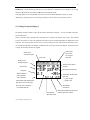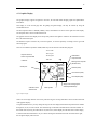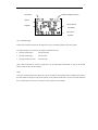
1
FILSER ELECTRONIC GMBH
•
LX5000
GPS and FLIGHT DATA SYSTEM
USER’S MANUAL
(version 6.0, 6.0 IGC, 7.0 and 7.0 IGC)
1
Introduction
The difference between the program versions 6.0 and 7.0:
All the vario and navigation functions are the same, but the program version 7.0 enables the use of the ATR 720
radio, which is functioning like a “black box”. All the differences in procedures are described in this manual.
The basic difference between the versions 6.0 and 6.0 IGC is a hardware modification which makes the IGC
version the official version according to the FAI rules. As far as the handling is concerned there are no
differences between the two versions, but the flights in the V6.0 lack the integrity check. The V6.0 has smaller
memory capacity (30 hours). The LX5000 is a state of the art variometer system, combining most modern GPStechnology and a variometer-system proven over the years.
Please, read this manual carefully in order to familiarize yourself with the LX5000, before installing it in the
glider.The best way of doing this, is to practice the functions described in this manual at home, with the
instrument connected to the battery or the battery charger.The LX5000 facilitates easy operation, requiring only
minimum operator action during flight, if the required flight data are entered on the ground.
Please, note that the airport data (i.e.frequencies and various altitudes) stored in the LX5000 may not be valid
any more, even after a very short time. For this reason, such data as well as the GPS navigation system should
only be used to support conventional navigation, and not to replace it. Thorough flight-preparation using
standard documentation is therefore strongly recommended.
FILSER ELECTRONIC will not be liable for, or guarantee the correctness and completness of this manual.
Hardware and software are subject to alterations.
This manual was written to the best of knowledge and belief. However, printing errors and other mistakes
cannot be completely omittet. WE are looking foreward to receiving your suggestios and comments.
Our address is:
FILSER ELECTRONIC GmbH
Gewerbestraße 2
D-86875 Waal
Tel.: +49 (0)8246/9699-0
Fax.: +49 (0)8246/1049
I
CONTENTS
1 GENERAL DESCRIPTION ----------------------------------------------------------------------- 1
1.1 Technical Data--------------------------------------------------------------------------------------------------------- 1
1.2 Variometer System --------------------------------------------------------------------------------------------------- 1
1.3 Electronic Altimeter -------------------------------------------------------------------------------------------------- 2
1.4 GPS Navigation ------------------------------------------------------------------------------------------------------- 3
1.5 Final Glide Calculator ----------------------------------------------------------------------------------------------- 3
1.6 Flight recording ------------------------------------------------------------------------------------------------------- 4
1.7 Airport and Turnpoint Database ---------------------------------------------------------------------------------- 4
1.8 Geographic Coordinates--------------------------------------------------------------------------------------------- 4
1.9 Glider Polars ----------------------------------------------------------------------------------------------------------- 5
2 INSTALLATION ------------------------------------------------------------------------------------- 6
2.1 Mecanical Installation------------------------------------------------------------------------------------------------ 6
2.2 Antenna ----------------------------------------------------------------------------------------------------------------- 7
2.3 Pneumatic Connection ----------------------------------------------------------------------------------------------- 8
2.4 Cabling ------------------------------------------------------------------------------------------------------------------ 8
3 OPERATION --------------------------------------------------------------------------------------- 10
3.1 Operating Elements ------------------------------------------------------------------------------------------------- 10
3.2 Selecting and Editing Data ----------------------------------------------------------------------------------------- 11
3.2.1 Setting the Wingload---------------------------------------------------------------------------------------------- 12
3.2.2 Ajusting the McCready setting --------------------------------------------------------------------------------- 12
4 DISPLAY DESCRIPTION ----------------------------------------------------------------------- 13
4.1 Gliding Navigation Display 1 -------------------------------------------------------------------------------------- 13
II
4.2 Gliding Navigation Display 2 -------------------------------------------------------------------------------------- 14
4.3 Graphics Display ----------------------------------------------------------------------------------------------------- 15
4.4 Arrival Display ------------------------------------------------------------------------------------------------------- 17
4.5 Information Display ------------------------------------------------------------------------------------------------- 18
5 MENU STRUCTURE ----------------------------------------------------------------------------- 19
5.1 Airport (APT)Mode ------------------------------------------------------------------------------------------------- 20
5.1.1 Team ----------------------------------------------------------------------------------------------------------------- 22
5.1.2 Wind------------------------------------------------------------------------------------------------------------------ 22
5.2 Turnpoint (TP) Program ------------------------------------------------------------------------------------------- 23
5.2.1 Quick turnpoint ---------------------------------------------------------------------------------------------------- 24
5.2.2 Selection of a Task (TSK) ---------------------------------------------------------------------------------------- 27
5.2.3 Editing a Task (TSK EDIT) ------------------------------------------------------------------------------------- 28
5.2.4 Programming a new Task (NEW)------------------------------------------------------------------------------ 29
5.2.5 Deleting a Task (DELETE) -------------------------------------------------------------------------------------- 29
5.2.6 Declaring a Task (DECLARE)---------------------------------------------------------------------------------- 29
5.2.7 Flying a Task (TSK)----------------------------------------------------------------------------------------------- 31
5.2.8 Starting a Task ----------------------------------------------------------------------------------------------------- 32
5.2.9 Restarting a Task (TSK Restart) ------------------------------------------------------------------------------- 33
5.2.10 Simple Task ------------------------------------------------------------------------------------------------------- 33
5.3 SETUP Program ----------------------------------------------------------------------------------------------------- 35
5.3.1 QNH RES ----------------------------------------------------------------------------------------------------------- 38
5.3.2 INIT ------------------------------------------------------------------------------------------------------------------ 39
5.3.3 DISPLAY------------------------------------------------------------------------------------------------------------ 40
5.3.4 PC (Personal Computer) ----------------------------------------------------------------------------------------- 40
5.3.5 Password ------------------------------------------------------------------------------------------------------------ 42
III
5.3.6 TP --------------------------------------------------------------------------------------------------------------------- 42
5.3.7 TSK------------------------------------------------------------------------------------------------------------------- 43
5.3.8 GPS ------------------------------------------------------------------------------------------------------------------- 43
5.3.9 Units ------------------------------------------------------------------------------------------------------------------ 43
5.3.10 Symbol-------------------------------------------------------------------------------------------------------------- 44
5.3.11 Airspace ------------------------------------------------------------------------------------------------------------ 44
5.3.12 NMEA -------------------------------------------------------------------------------------------------------------- 44
5.3.13 PC (Personal Computer Ajustments) ------------------------------------------------------------------------ 44
5.3.14 DEL TP/TSK------------------------------------------------------------------------------------------------------ 45
5.3.15 Polar ---------------------------------------------------------------------------------------------------------------- 45
5.3.16 TE Comp----------------------------------------------------------------------------------------------------------- 46
5.3.17 Audio --------------------------------------------------------------------------------------------------------------- 47
5.3.18 Input ---------------------------------------------------------------------------------------------------------------- 48
5.3.19 Output -------------------------------------------------------------------------------------------------------------- 48
5.3 Near Airport Program ---------------------------------------------------------------------------------------------- 49
5.6 Statistics Program --------------------------------------------------------------------------------------------------- 50
5.7 POS Program --------------------------------------------------------------------------------------------------------- 56
6 APPENDIX---------------------------------------------------------------------------------------------I
6.1 Wiring -------------------------------------------------------------------------------------------------------------------- i
6.2 Drilling Plan ----------------------------------------------------------------------------------------------------------- ii
1
1 GENERAL DESCRIPTION
1.1 Technical Data
Voltage
9-36 VDC
Power consumption (audio volume zero)
approx. 300 mA at 12 volts
Operating temperature
-20 to +60 degrees C (
degrees F)
Storing temperature
-30 to +80 degrees C (
degrees F)
Dimensions
∅80mm
LX5000
length 160mm (excluding connector)
approx.220mm (including connector)
Analogue instrument
∅57mm
length 100mm (including connector)
Total weight
approx. 1500 grams
GPS receiver
8-channel, parallel
Pressure probes
1 Silizium pressure probe for the altimeter(variometer)
and airspeed respectively
1.2 Variometer System
The variometer system consists of
• the total energy compensated variometer,
• the net-relative variometer,
• the interval integrator,
• the speed command,
• the audio generator.
The interval integrator calculates the average rate of climb over a certain time constant which may be selected in
the LX5000.
For the most common gliders a list of approximated polars is stored in the LX5000. The speed command signal
is generated using the polar you have selected from this list. Additional coefficients for glider polars not
contained in the list, may be calculated and stored in the LX5000. You may do this by using the computer
program „POLAR EXE“ which is contained in the scope of supply.
The signal is available on the analog instrument and on the liquid christal display, as well as through a tone
created by the audio generator. The mode and the frequency of the audio tone may be selected in the SETUP
program.
2
The parameters listed below influence the speed command signal:
• The McCready setting,
• the wingload setting,
• the glider polar,
• the wind,
• a correction to the polar, i.e. to compensate for bugs.
You may choose whether you wish to enter the wingload in kg/m² or in lb/ft². It is also possible to calculate the
wingload in percent over the basic weight that has been used to calculate the selected glider polar. The
loadfactor may be increased in 10%-steps to a maximum of 60% (=1.6 times the basic weight).
The decreement on the polar for a contaminated wing may be applied in 2.5%-steps up to a maximum correction
of 30%. It is effective over the whole speed range of the polar.
The variometer may be dampened through a variable filter, which may be selected in the SETUP program:
• a small filter (value low)
• a large filter (value high)
for quiet air
for rough air.
1.3 Electronic Altimeter
The electronic altimeter is operated via state of the art temerature compensated pressure sondes. All heights
indicated in the LX5000 are barometric heights. They are not GPS-heights.
After switching on the LX5000, the display shows the elevation of the airfield closest to your last landing site.
This infrmation is taken from the data base. You are then asked to enter the present elevation and the local
altimeter setting (QNH). This step is necessary, as the LX5000 requires the barometric pressure for an altimeter
reference, in order to make inflight corrections to the electronic altimeter possible. If the local altimeter setting is
not available, it may be read in the airpressure window on your barometric altimeter after setting the indicator to
field elevation.
A pressure correction on the electronic altimeter during flight will only be possible if, on starting the
LX5000 the local altimeter setting (QNH) was entered
3
1.4 GPS Navigation
Using the GPS-navigation system, the LX5000 calculates position data with great precission. Containing a
global model of magnetic variation, all courses calculated by the GPS are magnetic. GPS-speeds are ground
speeds
Therefore the speed indicated by the GPS may differ from the speed shown on the pneumatic airspeed indicator,
i.e. through the altitude error or a wind componenent.
The parameters calculated by the GPS are listed below:
• Magnetic track (TRK)
• Magnetic bearing to the turnpoint (BRG)
• Groundspeed (GS)
• Distance to the turnpoint (DIS)
• Estimated time of arrival at the turnpoint (ETA)
• Estimated time enroute to the turnpoint (ETE)
• Preselected magnetic track to the turnpoint (DTK, desired track)
1.5 Final Glide Calculator
The final glide calculator in the LX5000 calculates the deviation fron the required glidepath with reference to
the actual distance to the next turnpoint, taking into account the safety height you have selected in the SETUPprogram. The quantitative deviation from the calculated glide path is shown in digital figures on the display, i.e.
-320m.
The LX5000 has five options to calculate the wind, which may be selected in the navigation programs.
The wind (direction and velocity) required for the calculations during flight is calculated automatically and
continuously updated and accounted for.
If the last turnpoint is close to the destination and the final glide altitude can be reached before passing it, this
turnpoint may be programmed as a check point.
If you fly away from a programmed turnpoint or airport, the altitude required to return is calculated, taking into
account the present windcomponent and the safety height (turn-around-point).
If there is no GPS-reception for more than 60 seconds, the LX5000 will automatically switch to calculating the
distance by the use of the total air pressure. The last distance to the programmed turnpoint as calculated by the
GPS will be used as basis for calculation.
4
1.6 Flight recording
The flight recorder integrated in the LX5000 records the position, the altitude and the vertical speed every
twenty seconds during flight. For evaluation, this data may be viewed, saved and printed using a portable
computer or a notebook.
The LX5000 has a memory capacity sufficient to record 30 hours flight time. After the storage space is filled the
oldest data will be overwritten. Thus the last 30 hours recorded flight time will always be available.
1.7 Airport and Turnpoint Database
Approximately 5000 airports, 600 turnpoints and 100 tasks with up to 10 turnpoints each,may be stored in the
LX5000. On delivery several thousand airports (i.e. of Europe) are stored. Using a personal computer or the
controls of the LX5000 these may be called up, edited, added to or deleted easily. As an exeption airports can
only be added to or deleted from the airport file by using a personal computer. A diskette containing the program
LXGPS is in the scope of supply.
Please note that FILSER ELECTRONIC cannot be liable for the correctness and relevance of the airportand airspace data stored in the LX5000.
1.8 Geographic Coordinates
The geographic coordinates may be entered in degrees, minutes and either seconds or tenths of minutes.
Latitude:
N/S
DD.MM.mm or DD.MM.SS
Longitude
W/E DDD.MM.mm or DDD.MM.SS
(N= North, S= South)
(W= West, E= East)
DD= degrees
MM= minutes
SS= seconds
mm= tenths of minutes
You may convert seconds into tenths of minutes using the formula below:
Tenths of minutes= seconds/ 0.6
Before entering geographic coordinates using existing publicatons, you should note the format used. You may
either select the format in the SETUP-program or recalculate the last digits of the coordinates before entering
them..
5
1.9 Glider Polars
Presently a list of 30 speed polars for the most common gliders is stored in the LX5000. You may select the
required polar in the SETUP-menu. Two additional polars may be defined and stored for gliders not contained in
the list.
All polars used are defined by three coefficients (a, b and c). Using the computer program POLAR EXE these
coefficients may be calculated for any glider. Three polar coordinates must be taken from the speed polar of the
respective glider (speed /sinkrate) and entered into the computer program. The three coefficients are then
calculated and may be added to the list in the LX5000. It has prooven to take the coordinates at speeds of 100,
130 and 160 km per hour
6
2 Installation
Please read the instructions below carefully before installing the instrument in the glider.
2.1 Mecanical Installation
A new method is being used for mounting the LX500 in the instrument pannel. The axils of the four main turn
knobs (selectors) are at the same time the center axils for the fastening screws. This makes it possible to save
space on installaton while using standard instrument size. Drilling plans for the instrument cutouts are available
in the appendix.
For the installation please follow the instructions below. Also see Fig. 1: Mounting the LX5000 operating
element.
• Prepare the cutouts in the instrument pannel according to the drilling plans.
• Remove the inscripted covers from the four main selectors on the LX5000.
• While holding the selectors, open the screws which are now visible with a screwdriver. Now the selectors
may be removed.
• Using the special screw diver, which is delivered with the instrument, remove the four special type screws.
• Now position the LX5000 in the cutout in the instrument pannel.
• Fasten the LX5000 with the special screws, using the special screwdriver.
• Now the turn knobs and the covers may be fastened again.
selector axle
instrum ent pannel
specialtype screw
LX5000
inscripted cover
selector
Fig. 1: Mounting the LX5000 Operating Element
7
2.2 Antenna
The GPS-antenna delivered with the instrument should be installed such, that it will not be shielded from above.
The top of the instrument cover is considdered the best location. It may also be installed under the cover, if the
cover is not made of carbon fibre or metal and there are no other instruments installed above the antenna such as
a compass or solar pannels.
Please, note that the antenna should not be shielded by metallic parts. It should not be installed close to the
magnetic compass.
To achieve optimum reception you should test the antenna at different locations before finally installing it.
When laying the antenna cable the following principles shopuld be accounted for:
• Avoid kinking the cable.
• Lay cable in largest radii possible.
• Do not roll or bundle it up, and do not wrap it around the antenna or other objects.
• Do not lay it together with or close to electrical- or other antenna cables (e.g. radio cable).
The antenna included for the installation, is suted exclusively for use inside the glider. An antenna for external
installation is available from FILSER ELECTRONIC as an optional part.
2.3 Pneumatic Connection
Three pneumatic connection pieces are mounted on the rear of the LX5000. These must be connected to the
static pressure, the total pressure and the total energy compensation probe in the glider, as shown in figure two.
Caution:
Depending on the type of compensation used, either pneumatic or electric, please note that there is a
difference in how the respective pneumatic lines must be connected.
8
a) LX5000 TE-compensated using pneumatic TE-probe
LX5000
Ptot
total pressure
Pst
static pressure
pneumatic TE-probe
Pst (TE)
b) LX5000 electronic TE-compensation
Ptot
total pressure
Pst
LX5000
static pressure
Pst (TE)
The illustrationshows the LX5000 top view
Fig. 2: Pneumatic Connections
Caution:
Blowing into the pressure probes will damage the equipment. In this case repair on warranty is not
possible.
2.4 Cabling
The scope of supply for the LX5000 includes all cable assemblies necessary:
• cable Electrical power supply including the connectors for a personal computor and extensions.
• Analog wiring including the connectors for the loudspeaker, the analog indicator and the external speed
command/variometer reversing switch.
• 485 databus for the LCD vario display, compas and Doppelsitzer ??? connector (all three should be
connected parallelly)
The two non-interchangable 15 pin connectors on the cable assembleys will connect to the rear of the LX5000.
They should be secured with the locking screws.
The two bared ends on the electrical power supply cable connect to the electrical power supply of the glider.
The cables in the glider should have a large diameter. You should see to a good ground connection.
The RED power supply must be protected by a fine wire fuse (1.0 Amps)
red end= + powersupply
9
blue end= - ground
10
The panel jack on the interface line for the personal computer may be installed in the instrument pannel. The
interface cable to the personal computer COM-port (scope of delivery) may be connected here.
The loudspeaker will connect to the analog wiring through the CINCH- plug. It should be installed as far away
from the magnetic compas as possible to avoid deviaton through the magnetic field of the speaker.
The temperature probe contained in the analog wiring should be installed in the fresh air duct of the glider.
The cable to the flap switch marked SC need not be connected if the external speed command/variometer switch
(i.e. magnetic operated proximity switch switch on the flap handle or a maual switch) is not used.
The cable marked VAR PRIOR may be connected to a simple ON /OFF switch and may be installed in the
instrument pannel. If the switch is closed the LX5000 will always be in the vario-mode, regardless of the
position of the flap switch or the setting of the automatic speed command.
The cable marked NMEA will only be needed with an external moving map system,e.g. handy Map
You will find an exact wireing diagram in the appendix.
11
3 Operation
The LX5000 was designed for simple and operator-friendly use. Even a short familiarisation will allow you to
make good use of the LX5000 during flight.
3.1 Operating Elements
5 turn knobs (selectors), 1 potentiometer including the ON /OFF switch, and three push buttons are used to
operate the LX5000(see fig. 3 below).
ESC- (ESCAPE-)
button
ON/OFF switch
and Volume
START button
ENTER-button
MODEe selector
control
UP/DOWN(scan)
selector
ZOOM-selector
McCREADY setting
BALLAST setting
selector
selector
Fig.3: LX5000 Operating Controls
12
The operating controls function as described below:
Function:
ON/OFF-switch
Switches the LX5000 ON and OFF. With the instrument switched on, the ON/OFFswitch controlls the volume for the audio functions.
MODE selector
The MODE selector is used to select the various program modi in the LX5000.Also
see para. 4.6 MENU STRUCTURE.
UP/DOWN
The UP/DOWN selector is used to select entries, to scan the alphabet or change
selector
the numbers 0 to 9 up or down and for selecting pages within the menus.
ZOOM
The ZOOM selector zooms the graphic displays with reference to the selected
selector destination. In the APT andTP mode a DTK may be selected
(preselectedcourse). When entering alphanumeric data(i.e. to select a
turnpoint) the
cursor may be moved back and forth with the ZOOM selector.
McCREADY selector
Self explaning. The selected setting is shown in the display above the selector.
BALLAST selector
the setting may be entered in kg/m², lb/ft² or in % above the basic weight.
ENTER push button
Using the ENTER push button, entries are confirmed or activated and menus or
entry fields opened
ESCAPE push button
The ESCAPE push button is used to skip entries or to return from the APT; TP, or
TSK edit modes to previous displays.
START button
For starting pre-programmed tasks(available only when airborne), for storing the
current position as a turnpoint(available only in TP-mode) and for operating the
stopwatch (available only in POS-mode) as well as for setting the cursor back
during the editing procedure.
In the APT-navigation program the complete APT name will be displayed
momentarily upon pressing the START button.
3.2 Selecting and Editing Data
Selecting and editing data in the LX5000 is done according to the same pattern in all programs. The aim was to
achieve a user-friendly and easy to learn operation through simple and logical procedures
If a program is selected where data (i.e. a combination of letters for a turnpoint name) may be entered, the cursor
will flashon the first digit of the input field. You may now enter alpa-numerical data by scanning the alphabet or
the numbers 0 to 9 using the UP/DOWN selector. Each digit must be confirmed with the ENTER push button.
The cursor will move to the next digit
13
Pressing the ESCAPE push button, the entire input field will be skipped. This may be necessary if you wish to
avoid pressing ENTER numerous times in order to confirm data already contained in the input field.
Example: Entering the Airfield Elevation
After switching on the LX5000 you are asked to enter the present field elevation.
Using the UP/DOWN selector you should enter the data in the position indicated by the cursor and confirm it
with ENTER. If the altitude indicated in the inputfield was correct the whole field may be skipped using
ESCAPE, or each figure may be confirmed by pressing ENTER.
In summary:
• Confirming an entry :
press ENTER pushbutton
• Skipping an entry :
press ESCAPE pushbutton
• Returning the cursor to the left :
press START pushbutton.
This entry procedure is used for all inputs in the LX5000
3.2.1 Setting the Wingload
Using the ballast selector, the current wingload may be entered in kg/m², lb/ft² or in percent over the basic
weight used to calculate the glider speed polar.
You may select the desired unit of meassurement in the SETUP program.
Example for Calculating the Wing Load in Percent
Assuming a glider polar based on a wingload of 35 kg/m² was entered in the LX5000, the current Wingload
however is 42 kg/m²:
current wingload
Required ballast setting in %= -----------------------=
basic wingload
42 kg/cm²
-------------- = 1.2
35 kg/cm²
In this example a ballast setting of 1.2 (20 % increase over the standard wingload) should be used. Independent
of the unit used, the selected setting will be shown in the display above the BALLAST selector.
3.2.2 Ajusting the McCready setting
The McCREADY selector is used to ajust the McCready setting. The selected setting will be shown in the
display above the McCREADY selector.
14
4 Display Description
The figures below show the displays of the LX5000 and the data shown.
4.1 Gliding Navigation Display 1
With the LX5000 the GLIDING navigation display is probably the display used most.
In the modi APT, TP and TSK two different gliding navigation displays are available, which may be selected in
the SETUP program alternatively. First a description of display 1:
All values shown in the display refer to the turnpoint shown in the top line.
Please, remember all courses displayed in the LX5000nare MAGNETIC.
BRG magnetic bearing to the turnpoint
DIS
distance of the glider to the turnpoint
GS
indicates present groundspeed
TRK shows the magnetic track above ground
Active mode:
Name of selected
turnpoint
Fig.4: Gliding Navigation Display 1
ICAO-code
APT: aitport
TP: turnpoint
(turnpoint)
TSK: task
Magn. bearing to
turnpoint(desired
Distance to turnpoint
track)
shown in headline
Ground speed
Ground track
Speed command:
Graphic glidepath deviation
PUSH: fly faster
indication:Arow pointing up: glider
PULL: fly slower
too low-Arrow pointing down: glider
above glidepath
Windcomponent:
+ -> tailwind
Quantitative deviation from glide-
- -> headwind
path:
+ -> glider high
V/S integrator
indication
McCreadysetting
(above glidepath)
- -> glider too low
Track deviation indication:
Wingload setting (absolute
Arrow pointing right: desired track is to the right
or relative)here: relative
Arrow pointing left: des. track is to the left
Æcommand mode
Fig. 4: Gliding Navigation Display 1
15
PUSH/PULL= speed command. W indicates the wind component as calculated by the LX5000, A the average
climb rate, Mc the McCready setting, and B the selected wingload setting.
In the right bottom corner the quantitative deviation from the calculated glidepath is shown,e.g.-320m.
Additionaly a symbolised arrow above the figure indicates in the direction of the required correction.
4.2 Gliding Navigation Display 2
The gliding navigation display 2 offers the same basic information as display 1. It is also available in the APT;
TP and TSK modes.
However instead of the groundspeed the calculated wind is indicated in direction and velocity. The ndicated
average rate of climb, as well as the quantitative deviation from the calculated glidepath are emphasised in bold
characters. The course deviation arrow will vary in size according to the size of the actual deviation from course.
As an additional information the altitude is indicated in the lower right corner of the display. The desired unit m
or ft may be selected in the SETUP program.
Active mode:
Name of the
APT: airport
selected turnpoint
TP: turnpoint
ICAO-code
TSK: task
Bearing to the
selected waypoint
Distance to the selectd
waypoint
Ground track
Wind direction and speed
Integrator
Speed command:
Quantitative deviation from
PUSH: fly faster
glide path:
PULL: fly slower
+ -> glider to high
The deviation from selected track:
- -> glider to low
right arrow: track is to the right
left arrow: track is to the left
Altitudemeter
-Æ Command indicator
(barometric)
Wing load adjustment (as absolue or
The selected
McCready-value
Fig 5:Gliding Navigation Display 2
relative value) here: relative
16
4.3 Graphics Display
The graphics display supports navigation in the APT, TP and TSK modes through graphic and alphanumeric
information.
This display is on the second page after the gliding navigation display, and may be selected by using the
UP/DOWN selector.
The most important data i.e. BRG(B), TRK(T), GS(G) and Distance are shown on the right side of the display.
The turnpoint name is shown in abbreviated form.
The graphics section of the display shows the present position of the glider in relation to the srelected course and
the to the selected turnpoint.
The different airspace structures may be shown together, or selected seperately according to their type inthe
SETUP program.
There are two different symbols available,which may also be choosen in the SETUP plrogram.
Active mode:
Airspace structure,
shown only if activated
in SETUP
APT:airport
TP:turnpoint
TSK:task
Abbreviated
turnpoint name
Bearing to the turnpoint
(desired track)
Finish point
Distance (DIS)
Ground track (TRK)
Groundspeed (GS)
Image scale of the graphics
Indication of the
Glider symbol
window (ZOOM-factor)
desired track
Fig.6: Graphics Display
If there are not enough satelites received for position fixing, the warning GPS BAD is shown on the bottom line
of the graphics display.
Using the ZOOM selector you may change the range of the area displayed around the turnpoint between 200 km
through 100, 50, 20, 10 and 5 to2 km. The selected range is indicated on the bottom line in the data window. In
the TASK mode Z (zoom) plus TSK LEG or FS (foto sector) will be displayed in the data section of the display,
as selected with the ZOOM selector. If you continue turning the UP/DOWN turn knob one detent to the right,
the navigation display will be shown.
17
4.4 Navigation Display
The information necessary to navigate to a certain point are shown in this display as in the gliding navigation
displays. However, instead of the information related to gliding, a scale is shown on the bottom line of the
display. Here any deviation from the desired track is indicated. The desired track may be preselected using the
ZOOM selector if the Navigation display is active. This function resembles a track selection with an omni
bearing selector on a VOR course deviation indicator.
All values calculated and shown in the display refer to the turnpoint shown in the head line.
• DTK
preselected using the ZOOM selector. It resembles a preselected VOR course. (Magnetic
course to turnpoint). This function is not available in TSK mode!
• CDI
shows the deviation from the preselected course (DTK).
• XTE
(Cross track error) shows the deviation from the preselected course in units of distance
• MT
Magnetic track only by magnrtic compass option
• HDG
Compass (heading )
Active mode:
APT: airport
Magn.bearing to
turnpoint(desired
ICAO-code
TP: turnpoint
TSK: task
track)
Ground track
Distance to the turnpoint
shown in headline
Desired track (DTK),
preselected using
Ground speed
ZOOM-selector (not
in TSK-Mode)
Course deviation
Shortest distance to desired
indicator (CDI)
track (XTE, cross-track-error)
Fig.: 7 NavigationDisploay
If you do not need this display, it may be switched off in the SETUP program. See page 3.
If you continue turning the UP/DOWN selector one detent to the right, the arrival display will be shown.
18
4.5 Arrival Display
The APT, TP and TSK modes of the arrival display provide the user with current arrival data on the turnpoint
(turnpoint or airport) presently selected. The arrival display includes the following information:
ACT.T
time
ETA
estimated time of arrival
ETE
estimated time enroute
W
wind -direction and velocity
V
battey power
TC
traffic cirquit or turnpoint altitude
Active mode:
Name of selected
turnpoint
APT: airport
ICAO-code
TP: turnpoint
TSK: task
Time
Estimated time enroute
(ETE) to turnpoint and
Wind-direction
estimated time of
and velocity
arrival(ETA)at turnpoint
Battery power(volts)
Traffic cirquit altitude
of turnpoint ,airports
Temperature(external
only
temperature probe))
Fig.8: Arrival Display
If you continue turning the UP/DOWN selector one detent to the right, the INFO display will be shown, but only
if the wapoint selected is an airfield.
19
4.6 Informaton Display
The information display provides you with any data required when approaching an airport. For data not
published or available the respective positions in the display are filled with minus signs, ----.
Name of selected airport
ICAO-code, if known
Active mode:
(APT) or turnpoint (TP)
or available
APT:airport
TP: turnpoint
TSK:task
Turnpoint elevation
Main runway surface:
C: hard surface
G: gras
Main runway
Pattern alignment:
direction
I: unknownt
Traffic pattern
N: to north
altitude
E: to east
Main
S: to south
airport frequency
W: to west
Fig.9: Info Display
Note:
The Info display is shown only when the active turnpoint is an airfield. If a turnpoint is active, data like tower
frequency,traffic cirquit etc are not available.
20
5 Menu Structure
The illustration below shows the program modes of the LX5000. The modes may be selected with the MODE
selector from any mode or menu.
POS
NEAR
APT
TP
TSK
STAT
SETUP
AIRPORT
Turning the MODE selector
right
left
Fig 10: Program Modes
Presently there are seven different programs available with the LX5000:
POSITION
shows present position coordinates, the time, the date and stopwatch functions
NEAR APT
in this mode tracks and distances for the 10 nearest airports are calculated and shown
APT
to fly directly to an airfield and to edit the airport data base
TP
serves to fly directly to a turnpoint and to edit the turnpoint data base
TSK
serves to fly along a preplanned route (task) or to edit the route data base
The APT,TP and TSK modes also contain the menus for the wind calculation and the
team function
STATISTICS
indicates the statistics of the last flight when on the ground and inflight the current
flight
statistics
SETUP
here all system presettings are selected.
The APT and TP modes are almost identical, the only difference being that the APT mode is restricted to airport
related information. In the turnpoint mode however, both, information on turnpoints and on airports previously
entered into the TP data file,is available.
21
5.1 Airport (APT)Mode
In the airport mode, all functions related to airports may be executed. That is the navigation to an airport, the
graphical display, the information about an airport, as well as the management of the airport data file. Also the
modes for the wind calculation may be preselected here and the teamfunction is available. The two functions
mentioned last are also available in the TP and TSK modes.
Fig. 11 illustrates the menu structure of the APT program.
ESC
ENTER
UP-/DOWN
Fig.11: APT Mode Structure
You may reach the AIRPORT mode by turning the MODE selector until the APT display is shown. Using the
UP/DOWN selector the different subprograms may be selected. From each of these sub programs you can reach
the APT menus with ENTER. Here you will find the menus to select and edit airports, as well as the menu for
the team function (TEAM) and the menu to select the wind calculation mode (WIND). These menus are selected
with UP/DOWN and may be activated pressing the ENTER button.
22
Example: Selecting a new airport:
After having selected the AIRPORT program with the MODE selector you may activate the APT menu with
ENTER. Using UP/DOWN place the cursor on SELECT and activate the menu with ENTER. You will find two
ways to search for an airport:
a) Using ICAO code:
b) Using the name:
You may enter the ICAO code of the The entry field for the ICAO code may be skipped
airport you are looking for. Each digit using ESCAPE or by pressing the ENTER button
must be confirmed with ENTER.
four times.
If the airport is available, the LX5000 Using UP/DOWN the country may be selected and
shows the GLIDING NAV display with must be confirmed with ENTER.
the navigation data available for the
selected airport.
By entering the first four letters of the airport name
into the entry field with UP/DOW and ENTER the
airport may be selected from the APT file.
The bottom line of the display shows all airport
names covered by the searchword.
With UP/DOWN you may now select the airport
and activate it withENTER.
The GLIDING NAV display will be shown
displaying the navigation data for the selected
airport.
23
5.1.1 Team
The TEAM function enables pilots to meet enroute if, for example, teampartners have lost sight of each other or
intend to fly together.
Using TEAM you may fly directly to another aircraft’s position provided the other glider is equipped with a
GPS navigation instrument (preferrable LX5000). Both pilots must have the same turnpoint selected and
activated. Via radio, one pilot informs the other of his course and distance to the common turnpoint. The second
pilot enters the data into the LX5000, via the TEAM menu in the APT or TP mode.
Course and Distance to the first pilots position will be displayed on the second pilot’s GLIDING
NAVIGATION display.
5.1.2 Wind
The LX5000 offers six different modes to calculate the wind.
From either mode APT, TP or TSK the submenus may be reached and the menu WIND activated with ENTER.
The following options to calculate the wind are available:
FIX
the wind may be entered manually in direction and velocity as a fixed value.
(Entering the wind the units selected via SETUP must be taken into account).
The resulting wind component will be used for all calcolations.
GS
the wind is calculated using the ground speed while circling. This method requires a constant
indicated airspeed (IAS).
POS
the wind is calculated using the drift while circling e.g. thermaling.
COMB
the wind is calculated during straight and level flight. For good results small heading changes are
required.
COMPON
wind component TAS-GS only in straight fight ???
COMPASS the wind is calculated using the optional magnetic compass.
The pilot may decide which of the options he wishes to use. It is possible to switch betweeen the different modes
at any time, however only one mode will be active at a time. If for instance wait 6 is displayed instead of the
wind value, the pilot should make another six turns to complete the wind calculations.
Please note, the GS and POS modes are only active when circling, the COMB mode only in ‘straight and level’
flight. FIX uses a selected wind and there is no recalculation. COMPASS is only available when using a
magnetic compass which is available as option. The method is efective only by straight flight and when the track
is kept as constant as possible. For other notes see the LX5000 magnrtic compass manual.
24
5.2 Turnpoint (TP) Program
The APT and TP modes are mostly identical. The TP mode however refers to programmed turnpoints and
airports stored in the TP file , where the APT mode only refers to airports stored in the APT file.
Turnpoints (TP) are selected or edited as described in section 5.1 AIRPORT.
ESC
ENTER
UP /DOW N
Fig.12: TP Mode Structure
After having selected the TP mode with the MODE selector you may activate the TP menu with ENTER. Using
UP/DOWN you may then select the desired menu.
To search for an airport use SELECT. To change TP data use EDIT. To add a new turnpoint select NEW. To
delete an active turnpoint use DELETE.
25
If for example you activate the menu NEW, you are first asked whether or not you wish to copy an airport into
the turnpoint file: COPY APT DATA? N/Y. If you wish to do so Y (yes) must be confirmed with ENTER. The
selection is as described in section 5.1 APT.
If the question is answered with no N (no) you may add a new turnpoint to the turnpoint file:
After having activated the entry field with ENTER, the name and the coordinates of the new turnpoint may be
added to the turnpoint file as described above in section 5.1 APT. In both cases the new turnpoint will be
available for the TASK mode.
The functions TEAM and WIND are also available in the TP program.
Please note:
• Airports to be used as turnpoints in a task must first be written into the turnpoint file.
• When entering coordinates it is important to use the format preselected in SETUP (seconds or tenths of
minutes).
5.2.1 Quick turnpoint
Using the Quick turnpoint function you may store your present position as a turnpoint. To enable this the TP
mode must be active and position fixing via sattelite must be possible. The function is activated with START.
Fig.13: Quick-TP
The display will show e.g. TP: AP 14:24. With ESCAPE the present position may be stored, using AP and the
time as identifier. At a later time this identifier may be overwritten with a name, and may be stored in the TP
26
file. QUICK turnpoints may be activated and used as normal turnpoints. The name of the Quick-TP can be
configured by pilot himself. There are two different options, which are prviously selected in SETUP in the TP
menu. Anyway it is possible to select in the SETUP if to the Quick-TP will be flown imediatelly as to an
navigation point. This function can be very useful if ???
5.3 Task (TSK) program
100 tasks with up to 10 turnpoints each may stored in the TASK mode. All turnpoints and airports stored in the
turnpoint file may be used in a task. Airports to be used in a task must first be copied into the TP file.
ESC
ENTER
UP-/DOWN
Fig.14: TSK mode structure
27
The tasks may be displayed graphically. For the graphics display there are three different graphical modes
available:
Fig 15: TaskGgraphical Modes
The selection of the three graphical modes may be done with the ZOOM.selector. The TSK mode must be active
and the graphics display selectd.
The three graphics can not be zoomed as in the APT and TP mode. You may either select the whole task to be
displayed, the active leg of the task or the active foto sector. The active foto sector is the sector around the next
turnpoint in the task. The airplane symbol shows the present position in relation to the next turnpoint.
5.3.1 Selection of a Task (TSK)
After having selected the TSK mode with the MODE selector you may activate the TSK menu with ENTER.
Then confirm SELECT with ENTER.
In the headline of the display TSK SELECT and the number of the selected task are shown. Below the headline
the turnpoints are listed in sequence, numbered 0 to9. Points not programmed are marked NOT PROG.
Fig.16: Task Select
Using UP/DOWN you may scroll the 100 possible tasks. The selected task is then activated with ENTER.The
first point in the selected task, normally zero, is shown on the GLIDING NAV display. Until the task is started
in the air this point may be used for navigation to the start point. This is normally the departure airfield, but may
28
also be a displaced departure point. The the information for the first turnpoint is displayed only after the task is
started.
5.3.2 Editing a Task (TSK EDIT)
With the TASK EDIT menu you may invert the sequence of the turnpoints in a task. Turnpoints may be edited
or deleted. The last turnpoint before the destination may be entered as a checkpoint.
After having selected a task and the GLIDING NAVIGATION display is shown, and the TSK menu can be
reentered with ENTER. Using the UP /DOWN selector EDIT is selected, and activated with ENTER. The Task
is now shown on the display and may be edited.
You are asked whether you wish to invert the task. After entering either N or Y the total distance of the task and
of each task leg is shown, as well as the course of each leg.
The last turnpoint may now be programmed as a checkpoint by selecting the respective entry field with the
cursor. It may then be activated with ENTER.
To edit a turnpoint, the cursor is placed in the respective position with UP /DOWN and the entry field activated
with ENTER.
In the submenu shown on the display, SELECT, INSERT or DELETE may be selected and activated.
Choosing SELECT you are asked to enter the first four letters of the name of the desired turnpoint, using the
standard entry pattern. Now all turnpoints referring to the entry are displayed. UP /DOWN and ENTER will
select the desired turnpoint and write it into the task in place of the point that was selected for replacement.
Pressing ESCAPE instead of entering the name will display all turnpoints in alphabetical order.
a)To search for a name
b) Scrolling through all TP’s
The name of a turnpoint may be entered in Instead of entering a searchword, ESCAPE is pressed once.
abbreviated form in the entry field marked by All turnpoints will be shown in alphabetical order.
four stars.
The selection may be done with UP /DOWN and ENTER
Each digit must be confirmed with ENTER
Airports contained in the TP file must be selected using the first four digits of their name, not the ICAO code.
The procedure described above must be repeated for every turnpoint to be changed.
29
5.3.3 Programming a new Task (NEW)
A task may be programmed in parts or completely in the TSK EDIT submenu as described in section 5.3.2,
Edititng a task. You are recommended to use an empty task.
The menu NEW protects a programmed task against being overwritten.
As described in TASK SELECT an empty task is selected and NEW is activated. COPY TSK will only be
needed if an existing task is to be stored under a new task number. If this is not required, no N (no) may be
entered and an empty task will appear on the display.
After selecting INVERT N or Y and checkpoint CP N or Y, the cursor may be placed on the first turnpoint -0and activated with ENTER.
As in EDIT the submenu displays SELECT, INSERT and DELETE.
Using SELECT you may choose turnpoints from the turnpoint file and asign them to the turnpoints marked
before:
a)To search for a name
b) Scrolling through all TP’s
The name of a turnpoint may be entered in Instead of entering a searchword ESCAPE is pressed once.
abbreviated form in the entry field marked by All turnpoints will be shown in alphabetical order.
four stars.
The selection may be done with UP /DOWN and ENTER
Each digit must be confirmed with ENTER
This procedure is repeated until all turnpoints for the task are programmed. As soon as more than two turnpoints
are entered the LX5000 calculates and displays the total distance of the task. The distance and the course for
each leg are also displayed.
5.3.4 Deleting a Task (DELETE)
A task can only be deleted if it is activated. It may be deleted in the TASK menu DELETE, if Y (yes) is selected
and confirmed. Confirming no N (no) cancels deletion.
5.3.5 Declaring a task (DECLARE)
LX5000 offers the possibility to declare the task before the flight. There are two possibilities: current task can be
either selected among the tasks which are saved in LX5000 or newly created.
30
after Y and ENT
Task selected from TSK menu can be also edited if desired. The procedure is finnished by pushing ESC.
The following massage is displayed if the task has been declared proparly “TSK DECLARED”. During the
flight pilot can edit the this task or even select the other one, he also needn’t fly in a TSK menu. All these
procedures have no influence on the task declaring, but scoring in competitions is done accordingly to the
declared task. If the declared task has been changed during the flight, this flight is then under the FAI
regulations invalid.
If the copying of the task is not wanted, answer the COPY TSK DATA? question with N (look the figure
above).
IMPORTANT!
The badge or record flights have to be declared proprly before the take off.
5.3.5 Flying a Task (TSK)
In order to fly a task, you should note that:
•
The respective task must be programmed and activated.
•
You are recomended to recheck the programmed task before the flight. You may do this by selecting the
TASK EDIT submenu.
In all legs, the total distance and all courses are calculated and displayed. Possible mistakes may be
found and corrected.
•
A programmed task must be started manually by pressing the START button for at least one second
when passing the departure point or start line.
•
When passing a turnpoint, automatic switching to the next leg occurs when passing through the
turnpoint foto sector.
•
You may exit the TASK mode anytime to operate in another mode e.g. TP, APT or NEAR AIRPORT.
Before reaching a turnpoint or the destination you should return to the defined TASK mode in order to
get
complete documentation
Before a task is started the LX5000 provides all flight data e.g. track,distance etc in relation to the first point in
the task, normally programmed under zero.
31
5.3.6 Starting a Task
The foto sector or the circle around a startpoint or turnpoint may be preselected in the SETUP TASK submenu.
The size of the radii and through that the size of the sectors for the startpoint, turnpoint or finish point are
defined here.
Foto sector
Radius
Radius
Fig. 16: Foto Sector Modes
The table below ilustrates how a task is started and the switching to the next leg when a turnpoint is passed:
Fotosector
within
starting a TSK
Radius
outside
hold START-
hold START-button for
button for one
five seconds
within
automatic
outside
hold START-button for
five seconds
second
passing a
automatic
turnpoint
hold START-button for
five seconds
automatic
hold START-button for
five seconds
After you have completed a task, TASK END is shown until the glider has come to a full stop. This function is
controlled by toal pressure, not by ground speed as meassured by the GPS. To delete TASK END in flight, the
task must be started again by RESTART. You should note however, that parts of the task already flown will be
deleted from statistics.
32
5.3.7 Restarting a Task (TSK Restart)
Restarting a task may become necessary, for example, if you wish to start a task again for a second departure in
a competition. Activating RESTART will delete the statistics of those parts of the task already flown.
Fig. 17: TSK RESTART Menu
The function shown in fig. 17 may be activated with ENTER only if the TASK mode is active. The display as
shown in fig 18 below is shown after selecting RESTART with UP /DOWN and activating it with ENTER.
Fig 18:Confirmation of TSK RESTART
If you confirm RESTART with yes -Y- the task is reset. The first point in the task is shown on the navigation
display as turnpoint. When passing the startline or the foto sector for the startpoint the task may be started again
with ENTER.
Both displays are only available if a task was started during flight.
5.3.8 Simple task
This function is allways functioning in the APT and TP menu as long as no other TASK has been started.
Starting a task has higher priority. If ground speed of the glider exceeds the 50 km/h the current position will be
automatically saved as startpoint. If the glider is near the selected turnpoint or airport the current possition will
be stored as a turnpoint. Pilot can select any turnpoint or airport and continue the flight. If the flight is done in
graphic mode a cyilinder is shown around the turnpoint. When the glider is close to the turnpoint, the message
NEAR is displayed. The radius of the cylinder can be adjusted in LX5000 setup.
33
The statistic calculations are functioning as in TSK menu. If more than 10 turnpoints have been selected only
first ten will be calculated and displayed in statistic. The full flight statistic can only be calculated and seen on
your PC.
If the strting place is not wanted as startpoint it can be canceled by selecting a RESTART as in TASK menu.
The restart is reached by pushing the ENTER key, now the function can be selected and activated. After the
RESTART has been activated the current position is stored as a startpoint. The SIMPLE TASK function is very
useful when flying “Cats and Cradle” tasks. The landing place should be selected before the landing in order to
get the right statistic calculations.
5.4 SETUP Program
Any parameters necessary for the LX 5000 operation may be selected in the SETUP program.
Fig 19: SETUP-Mode
Fig 19 above shows the display after starting the SETUP program. The list of SETUP menus below explains
their meaning and how they may be activated.
QNH
RES
ENTER Æ
Å ESC
Selection of,
QNH,for barometric pressure corrections during flight
ALT. R = reserve height for final glide
BUGS = decreement on the polar,applied in 2.5%-steps up
to - 30%
INIT
ENTER Æ
Å ESC
Selection of,
Variometer filter, attenuation
34
Variometer integrator,variable 10, 20 or 30 sec.
Variometer indicator range, 2.5, 5 or 10 m/s
Speed command tone cutout range, between 0 and +/- 2 m/s
Automatic switching between Variometer and speed
command, OFF, GPS or airspeed controlled
DISPLAY
ENTER Æ
LCD-contrast, 0 to 100%
Å ESC
PC
ENTER Æ
Communikation via interface with personal computer
Å ESC
PASSWORD
ENTER Æ
Å ESC
Pasword entry, 96990, access to the SETUP-PASSWORD
menu
Fig. 20: Structure of the Setup Menu
The structure of the SETUP- PASSWORD menu is shown in the list below. These functions are only available
via the password 96990.
TP
Quick point default name definition and definition if this
point should be used as navigation point. Adjustment of the
NEAR radius by Simple Task
TSK
ENTER Æ
TSK-mode, selection of foto sector, radius, motor;
Å ESC
Start, TP or finish radius, 0.1- 9.9 km
GPS
ENTER Æ
Geodetic reference system selection,.norm. WGS 1984
Å ESC
UTC-offset entry for local time indication
UNITS
ENTER Æ
Selection of units, format of coordinates
Å ESC
Distance: km, nm, ml
Speed: km/h, mph, kts
Vert. Speed: m/s, kts
Wind: km/h, kts, mph, m/s
Altitude: m, ft
Load: kg/m², lb/ft²,“ OVERLOAD“
SYMBOL
ENTER Æ
Å ESC
airplane symbol for graphics displ, small or large
35
AIRSPACE
Selection of airspace structures to be displayed in the
graphics display
NMEA
ENTER Æ
Interface ON or OFF for,
Å ESC
GPGGA, GPRMC, GPRMB, GPGLL, GPR00, GPWPL,
GPLX1
PC
ENTER Æ
Å ESC
DEL TP / TSK
ENTER Æ
Å ESC
POALAR
ENTER Æ
Å ESC
LOAD
ENTER Æ
Å ESC
Comunication speed selection between LX5000 and
personal computer. Normally 19200 bps
Deletion of all turnpoints, and tasks, from the LX5000 TP
and TSK file. Confirmation Y (yes) or N (no)
Entry of a glider polar and glider type, USER1 oder 2, or
activation of a speed polar from the polar file
Entry of a default glider wing load value which is used by
LX5000 when it has been switched ON again. Selecting the
MINIMUM ??? If SET is selected the entered wing load
will be active imediately.
36
TE. COMP.
ENTER Æ
Å ESC
Selection of the electronic compensation strength and the
attenuation for the compensation filter between 1% and
150%.
Note, when using a pneumatic TE probe TE must be set
to 0 %
AUDIO
ENTER Æ
Å ESC
Audio generator settings, seperately for variometer and
speed command tone in both the negative and positive
range:
Tone frequency, mode, cutout range and audio-demo
Fortsetzung.............
INPUT
ENTER Æ
Reversal of polarity for the external speed command switch.
Å ESC
Low speed warning threshold gate (option)
External temperature probe, ON /OFF and.calibration
OUTPUT
ENTER Æ
Å ESC
Analog indicator; selection of mode, and installment of
maximum three instruments. Each instrument can indicate
variometer, speedcommand, net- and relative variometer
functions seperately
LCD IND
ENTER Æ
See LCD VARIO manual
Å ESC
COMPASS
ENTER Æ
Calibration of the magnetic compass (optional)
Å ESC
PAGE 1
ENTER Æ
Selection of Gliding navigation display one or two
Å ESC
PAGE 3
ENTER Æ
Å ESC
Fig 21: SETUP-PASSWORD-Menu
Navigation display ON or OFF
37
5.4.1 QNH RES
If on starting the LX5000 an altimeter setting (QNH) was entered, it may be altered in this sub menu. This may
be necessary if the barometric pressure has changed during a longer flight. Entering the new QNH will reset the
altimeter, providing correct altitude information for the final glide calculation.
In order to reach the airfield at a safe height allowing a normal traffic pattern, a safety height should be entered.
This height is added to the field elevation and taken account for in the final glide calculation.
LOGGER
In this menu all the necessary parameters for the FAI Logger adjustment can be found. There is no difference
between the versions 6.0 and 6.0 IGC, except that the version 6.0 lacks the intrgrity check. After opening the
menu, the following submenues are displayed:
In FLIGHT INFO the glider specifications and pilot’s name can be entered. LOGTIME is an important menu:
-total memory means total storage capacity (not free capacity)
-B-RECORD INT logging interval outside the turning point
-NEAR TP INT logging interval near the turning point
The NEAR TP INT is usually set to 1 or 2 seconds. By LX5000 6.0 it is recomanded to set B-RECORD to 20
seconds, so the total capacity is apr. 30 hours. If the B-RECORD is set to a smaller value the capacity will be
shortened.
5.4.2 INIT
The parameters listed below may be selected in the INIT menu:
VARIO FILT.
The variometer -filter allows a variable damping of the variometer
VARIO INT.
The time for the interval integrator may be preseleced here (normally20Sek.)
VARIO RNG.
Scaling range for the vertical speed indicator (2.5, 5 and 10 m/s)
TAB
Audio tone cutout in speed command mode between 0 to ±2m
38
AUTO SC
Automatic switching between variometer and speed command controlled by airspeed.
Automatic switching between variometer and speed command, controlled by GPS when
GPS
circling.
Switching between speed command and variometer controlled via external flap- or manual
OFF
switch
100 kmh
Airspeed selection for automatic switching by speed in the range between 100 and 160
WIND
km/h.
COMPASS
Wind calculations (adjustable from 15 to 30 sec)
Only if you have compass
39
5.4.3 DISPLAY
The contrast of the display may be ajusted to the prevailing light conditions and the angle of view. The contrast
may be varied between zero and 100 %
5.4.4 TRANSFER
This menu enables the comunication between LX5000 and:
-PC
-LX20
-LX21
-Colibri
Following data can be transfered (bidirectionally):
-TP and TSK database
(with LXFAI program from PC, LX20, LX21, Colibri)
-Headers (glider and pilot data)
(with LXFAI program from PC, LX20, LX21, Colibri)
-Logger transfer
(with LXFAI program from PC)
-Airport database
(with LXGPS program)
The data transfer with PC:
For transfer between LX5000 and PC, the LXFAI program is needed, this program is also used for comunication
with LX20, LX21 and Colibri FAI Loggers. The same program is also used to read data from LX5000 V6.0
IGC. Before starting the transfer process the SETUP mode should be active in LX5000 and the LXFAI should
be run on PC.
PC
LX 5000
Read Logger
Setup Logger
Read flight info
Write flight info
Read TP and TSK
Write TP and TSK
After pushing ENTER on LX5000 the message CONNECT is displayed, that means the communication
between these two devices has been astablished. PC acts as “master” and LX5000 as “slave”. As example the
pilot data transfer from PC to LX5000 will be described. Select the Write flight info on PC and push ENTER.
After some time the message DATA TRANSFER OK! Will be displayed. Please pay attention on the direction
40
of the transfer. As mentioned PC acts as master, so the command WRITE will always write data from PC to
LX5000.
The data transfer with LX 20, LX 21 and Colibri loggers:
The LX5000 combined with any of these loggers represents optimal and very comfortable solution. The flight is
prepared with PC and all the data are then written to the logger and before the flight also to LX5000. With these
procedure the use of portable PC is excluded (the logger plays it’s role) and the data in logger are the same as in
LX5000. When reading from logger the LX5000 acts as master. Here is a brief description:
The FAI LOGGER menu should be active on LX 20, by LX 21 and Colibri this isn’t necessary. The
TRANSFER has to be selected on LX5000. Please consider the following order:
LX 5000
LX 20
LX 21
ENTER
Read or Write
Green button
Colibri
Event button
Shortly after that the message WAITING FOR CONNECTION will be displayed on LX5000 and after the
connection has been established the beep tone of the logger will be heard and on the LX5000 the following
menu will be displayed:
READ TP/TSK
READ INFO
WRITE TP/TSK
WRITE INFO
WRITE SETUP
Write means the data transfer from LX5000 to logger, read has the oposite function. The procedure is ended by
pushinh the ESC on LX5000.
5.4.5 Password
The PASSWORD menu contains sub menus, where basic setups and data related to the glider, which remain
constant, may be entered. They are protected against inadvertent changes by a password.
The password can not be changed and reads:
96990
After entering the password (the tel.nr. of FILSER ELECTRONIC) the submenus in the SETUP PASSWORD
menu are available:
PASSWORD: 55556
After entering this password the integral GPS receiver is switched OFF and the device exepts the external
NMEA signal. This function can be deactivated by switching the instrument OFF or by rentry of the same
password.
41
5.3.5 TP
In this menu the default name of the Quick-TP can be selected. If the Date OFF is selected, the name is
composed of two different ASCII signs followed by current time. The ASCII signs used, can be selcted by user
??? If the two letters selected happen to be “TP” Quick-TP name will be TP08:39. Time 8:39 is the time when
the START button in the TP menu has been pressed.
The option Date ON offers the different art of your Quick-TP name composed of month, day and current time.
For instance if the Quick-TP’s name is 07160842, that means that the START button in the TP menu has been
pressed on the 16th of july at 08:42.
The option SELECT ON activates the applicated TP as the actual navigation point.
NEAR RADIUS has influence only when SIMPLE TASK is flown and defines a cylinder (0-9,9 km) which
should be overflown to accept this point as a TP of simple task.
5.4.6 TSK
The different modes for starting a task may be selected in this submenu. Also the size of the radii around the
turnpoints may be selected, which define the sectors, where switching to the next leg in a task occurs.
Presently there are two modes available:
• Radius
In the radius mode switching to a new leg occurs when flying through acircle around a turnpoint.
Starting or stopping a task occurs after passing through a defined circle around a start or finish point.
• Fotosector
Switching occurs when passing the defined foto sectors.
The radii defining the size uf the circles and sectors may be selected between 0.1 and 9.9 km.
5.4.7 GPS
The time the GPS operates with is UTC, former GMT. A time difference may be preselected to display the local
time on the clock:
• UTC + 0
UTC is indicated
• UTC + 1
indicates central European winter time
• UTC + 2
indicates central European summer time (daylight saving)
The GPS DATE is normally set to the Uniform Geodetic Reference System WGS 1984. It ajusts, in short, the
GPS coordinates systemto the earth’s surface. The selected reference system should not be changed as this will
decrease the precission of the navigation data.
42
5.4.8 Units
This submenu permits the use of various units of meassurement for the flightdata displayed.You may choose
between the units listed below:
• Geographic coordinates defining turnpoints in tenths of minutes or seconds
• Speed
km, nm,ml
• Vertical speed
m/sec, kts
• wind
km/h, kts, mph, m/s
• altitude/height
m, ft
• Wingload (LOAD)
kg/m², lb/ft², or OVERLOAD
OVERLOAD is an increase of the wingload setting in percent
of the basic glider weight, used to calculate the speed polar.
• QNH
the entry of QNH in mb, mm HG, inch HG
5.4.9 Symbol
The size of the aircraft symbol in the graphics display may be varied in this submenu.
5.4.10 Airspace
Here you may select the airspace structure you wish to be displayed on the graphics display:
• Airspace DISABLE /ENABLE
airspace display on or off
• CTR
control zones, airspace D
• R, P, D areas
restricted, prohibited, and danger areas
• TMA
terminal control areas, airspace E
• TRA areas
temporary restricted areas
• TIZ zones
identification zones
Any of theairspaces mentioned above may be displayed seperately or in any combination on the Graphics
Display. The function AIRSPACE may also be switched off entirely via DISABLE.
43
5.4.11 NMEA
Here the NMEA0183 interface is configuered. The interface may be used for connecting the LX5000 to external
appliances like a handy map. Data records may be switched on or off as required. Data records required for
specific applyances are normally available from the respective manufacturer. If there are no applyances
connected to the NMEA interface, all data records may remain deactivated.
5.4.12 PC (Personal Computer Ajustments)
The Baud-rate for communication between computer and LX5000 is ajusted in this sub menu. It is normally set
to 19200 Baud. Communication between LX5000 and Computer is only supported if the Baud-rate matches.
5.4.13 DEL TP/TSK
Here you may delete all turnpoints and tasks completely and irrevocably if you answer DELETE ALL TP AND
TSK with Y (yes). The airport file stored in the LX5000 can not be deleted.
5.4.14 Polar
The submenu POLAR contains 30 speed polars for the most common gliders. Any polar may be easily selected
and activated.
Two additional polars not contained in the file may be defined and stored.With the aid of the computer program
POLAR EXE (scope of supply) three polar coefficients may be calculated. The coefficients are entered in the
LX5000, POLAR submenu. The calculation is based on three coordinates taken from the speed polar. It has
prooven to take the coordinates at speeds of 100, 130 and 160 km/h. For MIN LOAD the weight should be
entered, that was used as basic glider weight to calculate the speed polar
44
5.4.15 TE Comp
In this submenu you may select the compensaton mode and, if using electronic compensation, the compensation
level.
It is important to note:
• Using a pneumatic total energy (TE) probe the compensation level must be set to 000%. Pneumatic TE
compensation can not be attenuated electronically.
• If you choose electonic compensation you may vary the compensation level using the TE function, and
attenuate the signal using TE F.
It is not possible to publish TE values for specific gliders, as electronic compensation depends on many
variables, just to mention static port location. A test flight in calm conditions will deliver the best results.
When doing the compensation flight you should consider the the points noted below:
• The air should be very calm
• LX5000 must be in VARIO mode, not in Speed command!
• Select SETUP program,TE-COMP menu
• Increase airspeed to 160 km/h (99 mph / 87 kts)and maintain for 20 sec.
• Slowly reduce airspeed to 80 km/h (50 mph / 43 kts). With optimum compensation the variometer will
indicate vertical speed versus airspeed congruent to the values in the speed polar.
If during speed reduction too much sink rate is indicated on the variometer, the selected TE setting must be
decreased (compensation too large).
If the variometer indicates not enough sinkrate or even climb, the TE setting must be increased (compensation
too small).The procedure above should be repeated until an optimum compensation is achieved. Settings
between one and 150 % are available.
The filter to dampen the signal may be varied between 0 and 9. The higher value increases the attenuation.
45
5.4.16 Audio
Various audio signals for the variometer and speed command mode may be selected via the AUDIO submenu.
The audio frequency, tone modes and various ranges for masking the audio signal in the speed command mode
are available:
SC
VARIO
Masking the audio tone including the choise of:
SC
audio tone in positive and negative speed command range
SC POS
audio tone in positive speed command range only
SC NEG
audio tone in negative speed command range only
Audio tone modes in vario-mode including the choise of:
LINEAR
normal audio tone over the whole variometer range
LIN/NEG
normal audio tone interrupted in negative variometer range
LIN/POS
normal audio tone interrupted in positive variometer range
DIGITAL
digital tone over the whole variometer range
DIG/NEG
digital tone interrupted in negative variometer range
DIG/POS
digital tone interrupted in positive variometer range
0%
Selection of the audio frequency (Herz) for zero indication on the analog variometer
+100%
Selection of the audio frequency (Herz) for max climb indicated on the analog variometer
-100%
Selection of the audio frequency (Herz) for max.descent indicated on the analog variometer.
You may listen to the selected audio tone in the the submenu AUDIO DEMO via loudspeaker.
5.4.17 Input
The INPUT menu enables you to select the analog indicator functions as shown in the list below:
SC INPUT
Overriding the external speed command switch
ON:
switch closed Æ speed command mode
switch open Æ variometer mode
OFF:
switch closed Æ variometer mode
switch open Æ speed command mode
STALL W.
The airspeed gate for the stallwarning may be selected. This feature
requires an external buzzer.
TEMPARATURE
The temperature indication may be swiched off if an external
temperature probe is not connected
TEMP. OFF (offset).
The external temperature probe may be ajusted by+/- 9°C
46
5.4.18 Output
Up to three analog instruments may be conneced to the LX5000. Any combination of indications as shown
below may be selected for both, the variometer and speed command mode.
VARIO
Indicates the „normal“ variometer signal
SC
Indicates the speed command signal
NETTO
Indicates the NET variometer signal
REALTIV
Indicates the RELATIV-variometer signal
OFF
Indicator off
The fig. below shows an example of theoptions available:
Analogindication 2:
Always net
variometer
Analog-indication 1
signal
shows:
Variometer-signal when
Analog-
in vario mode
indication 3:
Speed command signal
when in s/c mode
Fig. 22:Analog Indicator Configuration
47
5.5 Near Airport Program
The NEAR AIRPORT program continuously calculates data for the 10 airports nearest to your position. The
data listed below are shown on the display as seen in fig.23.
• The abbreviated name of the airport, 16 digits maximum.
• The bearing (BRG) to the airport.
• The distance to the airport.
Number of airports calculated (max. 10)
Names of
nearest
airports(APT)
Bearing (BRG) to
Distance to
airport
airport
Fig. 23:Near airport
Using UP /DOWN you may place the cursor onto the selected airfield. ENTER activates the marked airfield.
The program changes automatically to the APT mode and displays the navigation data for the selected airfield.
Note:
If GPS reception is not sufficient for navigation, GPS BAD is shown on the display. The GPS requires at least
five minutes continuous GPS reception to enable the NEAR AIRPORT mode.Only airports stored in the APT
file are available for navigation.
5.6 Statistics Program
The LX 5000 offers two different arts of the statistics:
• Statistics during the flihgt
• The logbook and the complete statistics with barogram and flight route for every flight which is included in
the logbook
STATISTICS DURING THE FLIGHT
48
There are two different levels: the flight statistisc and task statistics, which is avaliable only when the TSK has
been started (also by SIMPLE TSK). As soon as the statistics is selected by MODE selector switch, the statistic
display appears.
STATISTICS
FLIGHT:
12:30:22
13:30:22
12:30:22 is the start time (take off); 13:30:22 is the current
time
DURATION:
VARIO:
1:00:00
1,5 m/s 23%
duration of the flight
vario average and the Kurbelanteil ???
ENGINE: 12:20
the duration of the engine flight
The statistics is based on all the flown legs and also the actual leg. The task statistics can be activated by
UP/DOWN rotatory switch.
STATISTICS
TSK 00/1: GAP/AD
TIME: 12:00:00
the active TP
13:10:00
DURATION: 1:10:00
SPEED: 99 km/h
VARIO: 1,2 m/s
23%
ENGINE:
The awerage speed and diastance are shown also for the currently active leg. The next page displays the total
flight statistics.
STATISTICS
TSK00
10:43:22
--:--
DURATION:
10:43 is the start time (Abflugzeit) ???
0:12:23
the duration of the TSK
SPEED:
140 km/h
awerage speed
VARIO: 1,3 m/s
29%
vario awerage
ENGINE:
STATISTICS AFTER THE FLIGHT
This statistics is avaliable after the end of the flight. It is very important that the logger isn’t turned OFF at least
3 minutes after the glider has stopped. The tipical sign that the flight hasn’t ended is the abscence of the
LOGBOOK in statistics mode (the only shown statistics is the flight statistics). After selecting the statistics
mode the LOGBOOK appears:
49
The different flights are selected by UP/DOWN rotatory switch and after pushing ENTER the statistics is
displayed.
After pushing ENTER the following options are avaliable:
After selecting ROUTE :
and after ZOOM
The ZOOM function is activated by pushing ENTER. After that a cross is displayed in the middle, which is then
moved by UP/DOWN and ZOOM. After pushing ENTER the first corner is defined and in the same way the
second one. So the square, which will be zoomed has been defined.
Barogram:
and after ZOOM
The ZOOM function is activated by ENTER. After that a balk is displayed, which is moved by UP/DOWN
switch. After pushing ENTER the first point is defined and in the same way the second one should be selected.
Task:
The previously programmed task is displayed, which can also be changed in this menu (for instance one TP has
not been reached). It is also possible to enter some aditional turning points.
Statistics:
50
The CALCULATING procedure can take a few minutes (this depends on the length of the task and the
loggintervals). The different legs of the TSK can be selected by UP/DOWN switch.
The other leg statistics displays are reached by ZOOM switch:
The figures are showing:
-The take off altitude and the TP altitude; the flown distance; XT speed shows the altitude difference between
the departure point and the TP
-flight route between two TP (can be zoomed)
-Photo sector or cylinder (zoomed with ENTER); 3 cylinders 500, 1000 and 2000 m
-Photo sector or cylinder TP
In the same way all the legs can be analised (use UP/DOWN switch to select desired leg). All the legs are
numbered, for instance leg 1/3 means first leg of total three. By pushing the ESC key the statistics is brought to
the beginning.
5.7 POS Program
The POSITION program informs you about :
• The number of satelites received
• The status of the GPS receiver, 2D or 3D navigation or the coordinates of the LAST FIX
• The present position, coordinates latitude and longitude
• The barometric altitude
• The time, UTC or local as preselected in the INIT menu
• And shows the stopwatch if acivated with START
• with UP/DOWN switch other displays can be reached (altitude in meters and in feet, satelite constants and
signal quality)
51
Number of satelites received
GPS-status
Latitude
Present altitude
Longitude
(barometric)
Time, date or
stopwatch
,
Fig. 25: POSITION Display
Instead of the TIME the DATE may be displayed as long as the ENTER button is pressed and held.
The stopwatch may be activated by pressing the START button once,
• pressing START again
activates the timer
• pressing START again
stops the timer
• pressing START once more
resets the timer.
Only if this last function is active the normal clock can be reactivated with ENTER. As long as the ENTER
button is held, the date will be displayed.
Note:
LAST FIX is indicated when the GPS is not ready for navigation. During this time the coordinates last stored in
the GPS module are displayed. The present position is only indicated if the GPS is in 2D or 3D mode. Which of
the two GPS modes are active has no influence on the operation of the LX5000.
C
B
A
1
2
SD15 BU
Title
Size
Date:
File:
A3
3
Number
15-Oct-1997
C:\CSERVE\FCABINET\LX5000F.S01
4
5
5
3
2
LX5000
3m
5
3
2
LX20
1.5m
0.5m
0.5m
3
+8V
TEMP
MASSE
schwarz
weiss
schirm
2
VARIO PRIOR.
MASSE
schirm
1
SPEED COM.
MASSE
1
2
3
schirm
schirm
ANALOG3
OPTION
2
Sheet of
Drawn By:
5
5
0.5/3.5m
1
2
3
711-2-99-0076-00-03
schirm
3
3
3
3
2
3
GND
schirm
BINDER 5P
LX5000/LX20 KABEL
1
TXD
schwarz
09-0097-00-05
RXD
weiss
SD15 ST
1.5m
5
GND
schirm
0.5/3.5m
ANALOG2
OPTION
711-2-99-0076-00-03
BINDER 3P
1
3
TXD
SD9 ST
PC-RS232C
2
RXD
schwarz
SD9 BU
weiss
8
15
7
14
6
13
5
12
4
11
3
10
2
9
1
BINDER 3P
711-2-99-0096-00-05
GND
schirm
1
2
3
2
PC
4
9
5
B
schwarz
schirm
ANALOG1
BINDER 3P
50cm
20cm
7
+12V
weiss
0.5m
G
RS232C
1
6
A
+12V
1
2
LAUTSPR.
711-2-99-0076-00-03
schirm
STALL
WARNING
CHINC
gelb
rot
+12V/RS485
+12V
MASSE
rot
gelb
braun
1.0m
+5..+12V
H
20cm
rot
blau
12V HILFSSPANN.
OPTION
+12V
MASSE
12V HAUPTSPANN.
1
LX5000/LX500 PC KABEL
8
15
7
14
6
13
5
12
4
11
3
10
2
9
1
50cm
rot
blau
D
50cm
E
LX5000 I/O KABEL
F
LX5000/LX500 VERSORGUNGSKABEL
52
6 Appendix
6.1 Wiring
4
4k7
LM335Z
1
H
G
F
SD9 BU
Revision
BINDER
5P
E
D
SD9 BU
SD9 BU
C
B
A
53
6.2 Drilling Plan
6mm
°80.0mmh11
°89.0mm
Drawing not to scale.
To mount the plug on the interface cable in the instrument pannel, a hole of 9 mm indiameter is needed.
The cutout needed for the analog indicators conforms to standard with 2 1/4“
54
6.3 BZT Document of Registration