1
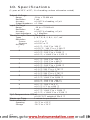
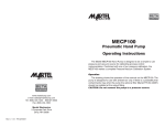
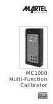
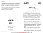
TC100
Precision
Thermocouple
Calibrator
Table of Contents
1.
2.
3.
4.
5.
Introduction . . . . . . . . . . . . . . . . . . . . .1
Accessories . . . . . . . . . . . . . . . . . . . .5
Set-Up Basic/Advanced . . . . . . . . . . .5
Operating Procedure . . . . . . . . . . . . .6
Operating Connections
and Precautions . . . . . . . . . . . . . . . . . .7
6. Battery Save Feature . . . . . . . . . . . . . .8
7. Setpoint Feature . . . . . . . . . . . . . . . . .9
8. Min/Max Datalogging . . . . . . . . . . . . .9
9. Maintenance . . . . . . . . . . . . . . . . . . . .11
10. Specifications . . . . . . . . . . . . . . . . . . .12
11. Warranty . . . . . . . . . . . . . . . . . . . . . . . .13
TC100
1. Introduction
The Martel TC100 is designed to be a simple to
use, high accuracy thermocouple calibrator
capable of either simulating or reading J, K, T,
L, E, R, S, T, B, C, or mV thermocouple types. A
standard thermocouple mini-connector along
with screw terminals for bare wire makes connections easy while providing direct contact
with the internal cold junction compensation
circuitry.
When used as a thermocouple simulator, the
TC100 provides control which allow the user to
either “step” in increments or decades.
1.1 Customer Service
Corporate Office:
www.martelcorp.com
e-mail: [email protected]
Tel: (603) 434-1433 800-821-0023
Fax: (603) 434-1653
Martel Electronics
3 Corporate Park Drive
Derry, NH 03038
1
1.2. Unpacking Your Calibrator
Remove the packing list and verify that all
equipment has been received. If there are any
questions about the shipment please call Martel
Electronics at 1-800-821-0023. When the shipment is received inspect the container and
equipment for any signs of damage. Note any
evidence of rough handling in transit.
Immediately report any damage to the shipping
agent.
NOTE: The carrier will not honor any claims
unless all shipping material is saved for their
examination. After examining and removing
contents, save packing material and carton in
the event reshipment is necessary.
1.3 Safety information
Symbols Used
The following table lists the International
Electrical Symbols. Some or all of these symbols may be used on the instrument or in this
manual.
Symbol
Description
AC (Alternating Current)
AC-DC
Battery
CE Complies with European Union
Directives
DC
2
Double Insulated
Electric Shock
Fuse
PE Ground
Hot Surface (Burn Hazard)
Read the User’s Manual
(Important Information)
Off
On
Canadian Standards Association
The following definitions apply to the terms
“Warning” and “Caution”.
• “Warning” identifies conditions and actions
that may pose hazards to the user.
• “Caution” identifies conditions and actions
that may damage the instrument being used.
Use the calibrator only as specified in this manual, otherwise injury and damage to the calibrator may occur.
3
Warning
To avoid possible electric shock or
personal injury:
• Do not apply more than the rated voltage.
See specifications for supported ranges.
• Follow all equipment safety procedures.
• Do not use the calibrator if it is damaged.
Before you use the calibrator, inspect the
case. Look for cracks or missing plastic. Pay
particular attention to the insulation surrounding the connectors.
• Select the proper function and range for your
measurement.
• Make sure the battery cover is closed and
latched before you operate the calibrator.
• Remove test leads from the calibrator before
you open the battery door.
• Do not use the calibrator if it operates abnormally. Protection may be impaired. When in
doubt, have the calibrator serviced.
• Do not operate the calibrator around explosive gas, vapor, or dust.
• When servicing the calibrator, use only specified replacement parts.
• To avoid false readings, which could lead to
possible electric shock or personal injury,
replace the battery as soon as the battery
indicator appears.
Caution
To avoid possible damage to calibrator or
to equipment under test:
• Use the proper jacks, function, and range for
your measurement or sourcing application.
4
2. Accessories
The following items are available for the TC100
calibrator.
Item
P/N
AC adapter/charger
1001-9V (120V)
80013 (220V)
9V NiCd battery
1002-9V
(must use with above charger)
TC wire kit (J, K, T, E)
80029
TC wire kit (R, S, B, N)
80036
3. Set-Up Basic/Advanced
FIGURE 1
5
Before beginning, become familiar with the keypad layout and the configuration of the
input/output jacks. See Figure 1.
In the basic or “as shipped” setup, the TC100
allows the user to step through all available T/C
types (10 plus mV). In certain situations this
may be confusing to infrequent users as to
which type to use.
The optional advanced setup mode allows a
supervisor through password control to “blank
out” or disable unwanted T/C types so that only
the proper T/C types can be selected. The following procedure outlines how this is done:
1. Hold down the TC TYPE key at power up.
2. The word PASS will be displayed and you
need to introduce the password 123 as
follows:
Rotate the knob to 1, press SET key, rotate
to 2, press SET, rotate to 3, press SET.
3. You can toggle through all the thermocouple
types by pressing TC TYPE key.
4. Press SET key for the ones that you want to
keep.
5. The last TC type is mV. By pressing TC
TYPE key again, you’ll exit from this mode
and return to normal operation.
6. If you missed one, repeat the entire procedure again.
4. Operating Procedure
1. Turn on power and select the desired thermocouple type by depressing the T/C Select key.
Once the desired T/C is selected, it will remain
in memory until a new T/C type is selected.
6
2. Select either Input or Output mode depending
on whether you want to read a thermocouple
or simulate a thermocouple signal.
3. Connect the appropriate thermocouple to the
mini-connector or screw terminals on the top of
the TC100. Note: for best accuracy, allow 3 to
5 minutes for the T/C connector (or wire) to
stabilize to the same temperature as the
connector block.
4. If you are using the TC100 in the output mode
use the cursor control keys to select the
decade to be controlled. Note that the cursor
is the line under a specific digit.
5. Operating Connections and
Precautions
1. When operating in the thermocouple output
mode, the TC100 has the ability to simulate
up to 10 T/C types plus mV into devices
which measure thermocouples:
NOTE: If the TC100 is improperly connected to
a low impedance load (either a short or near
short) the display will flash.
Thermocouple
mini-connector
Thermocouple
device under test
1Kohm or
greater input
impedance
Use thermocouple wire for
the type selected (e.g. if a
"J" T/C is being simulated,
you must use "J" wire.)
FIGURE 2
SIMULATING A THERMOCOUPLE OUTPUT
7
2. When operating in the thermocouple
Measure Mode the TC100 can be used to
read the temperature of a thermocouple
probe.
In this mode, the TC100 will detect an open
circuit should the thermocouple junction malfunction. In this case, the display will indicate
“OL”. It will also indicate “OL” if no probe is
connected in the Input Mode.
FIGURE 3
READING A THERMOCOUPLE PROBE
6. Battery Save Feature
The TC100 incorporates an Auto Shut Off or
Battery Save feature that will automatically turn
off the TC100 after a preset amount of time (up
to 30 minutes) The factory default setting is 30
minutes, but can be changed or disabled by
completing the following steps:
1) Turn on the TC100. Closely watch the display
during power up.
2) The display will indicate the amount of time
the battery save feature is set for (off to 30
minutes). Immediately adjust the knob to
change the time period or disable the function.
8
7. Setpoint Feature
The TC100 allows the user to program up to 3
setpoints for each TC type (including mV). to
set the setpoints complete the following procedure:
1) Turn on the TC100 and select the Source
Mode.
2) Select the TC type to be simulated and correct units (either °C or °F).
Recall
3) Press
to see what is currently
stored in each of the 3 setpoints.
4) To store a new value adjust the output to the
desired value then press the
Set
key.
5) Repeat steps 3 & 4 until all 3 setpoints are
stored.
6) Once the setpoints are stored, press the
Recall
key to recall the newly stored set-
points.
Recall
7) Each press of the
key will increment to the next stored setpoint.
Note: Setpoints are non-volatile and will
remain in memory until changed.
8. Min/Max Datalogging
When the TC100 is in the measure mode it will
continuously monitor and store the minimum
and maximum values for that particular input.
To operate the datalogging feature use the following procedure:
9
1) Place the TC100 in the measure mode.
2) Connect a thermocouple (or probe).
3) Clear the min/max memory by pressing both
keys (min and max) simultaneously. The
LCD will display “CLR” when the memory is
cleared.
4) Allow the unit to log min. and max. for as
long as required.
Warning: You may want to disable the Battery
Save feature before using the Datalogging
Mode to prevent the TC100 from turning off prematurely.
5) At any time press the min. or max. to display
the value stored.
6) Turning off the TC100 or changing modes
will clear the memory. Be sure to record
your data before turning off the unit.
10
9. Maintenance
A. Battery Selection
The TC100 operates on a standard 9V alkaline
battery or an optional rechargeable 9V Ni-Cd
battery. For most applications the 9V alkaline
battery will suffice; however, in heavy use applications the 9V Ni-Cd may be a better choice.
The 9V Ni-Cd battery supplied by Martel will
offer approximately 7 hours of continuous use
on a full charge (the alkaline battery will yield
about 25 hours). The optional 1001-9V charger
supplied by Martel will provide an overnight
charge rate (10-12 hours) and will also power
the TC100 for bench use while maintaining a
float charge on the Ni-Cd battery.
Warning: Never connect the AC adapter/
charger with the 9V alkaline battery installed.
To order the 9V Ni-Cd battery or AC
adapter/charger contact Martel Electronics at
800-821-0023.
B. Input Protection
The TC100 incorporates a fuseless input protection and will tolerate most misconnections
up to 250 VAC or 250 VDC for up to 30 seconds duration. Because of this protection no
fuse is required.
C. Calibration
The TC100 is designed to hold its rated accuracy for a minimum of one (1) year. It is therefore
recommend that an annual re-calibration be
done to ensure operation within specification.
Contact Martel’s Customer Service Department
for re-calibration information at
1-800-821-0023 or [email protected].
11
10. Specifications
(1 year at 23°C ±5°C; % of reading unless otherwise noted)
Output Voltage
Range
Resolution
Accuracy
Output Impedance
-10 to +75.000 mV
1 mV
±0.007 % of reading, ±5 µV
>1 Ohm
Input Voltage
Range
Resolution
Accuracy
Input Impedance
-10 to +75.000 mV
1 mV
±0.007 % of reading, ±5 µV
> 1 MegOhm
Thermocouple Source/Measure
Types
Resolution
Source
Measure
Accuracy
J
K
T
E
R
S
B
L
U
C
J, K, T, E, R, S, B, L, U, C, mV
±0.1°C or °F
±0.01°C or °F
±0.5 °C; -210 °C to -100 °C
±0.25 °C; -100 °C to +1,200 °C
±0.6 °C; -200 °C to -100 °C
±0.3 °C; -100 °C to +1,000 °C
±0.5 °C; +1,000 °C to +1,372 °C
±0.7 °C; -200 °C to -150 °C
±0.3 °C; -150 °C to +400 °C
±0.5 °C; -200 °C to -100 °C
±0.2 °C; -100 °C to +1,000 °C
±1.8 °C; 0 °C to 250 °C
±1.0 °C; 250 °C to +1,767 °C
±1.8 °C; 0 °C to 250 °C
±1.0 °C; 250 °C to +1,767 °C
±1.7 °C; 600 °C to 1,000 °C
±1.2 °C; 1,000 °C to 1,820 °C
±0.5 °C; -200 °C to -100 °C
±0.4 °C; -100 °C to +900 °C
±0.7 °C; -200 °C to 0 °C
±0.3 °C; 0 °C to +600 °C
±0.4 °C; 0 to °C 1,000 °C
±0.7 °C; 1,000 °C to +1,800 °C
±1.2 °C; +1,800 °C to +2,316 °C
CJC Temperature Offset
Warm-up Time
Environmental
Operating
Storage
12
±0.05 °C/°C outside of 23±5 °C
1 minute to specification
-10 °C to +55 °C
-20 °C to +70 °C
Power Requirements
Battery
9 Volt alkaline; 006P/ IEC 6F22/
NEDA1604
Optional NiCad
Optional AC adapter/charger
Mechanical Dimensions
5.7" x 3.15" x 1.43"
(14.47 cm x 8.00 cm x 3.63 cm)
Weight
12 ounces (340 grams)
Notes: 1.Temperature standard ITS-90.
11. Warranty
Martel Electronics Corporation warrants all
products against material defects and workmanship for a period of twelve (12) months
after the date of shipment. Problems or defects
that arise from misuse or abuse of the instrument are not covered. If any product is to be
returned, a “Return Material Authorization” number must be obtained from our Customer
Service Department. This number must be indicated on the return package as notice to our
Receiving Department to accept the shipment.
Any package not so marked will not be accepted and will be returned to the shipper. Martel
will not be responsible for damage as a result
of poor return packaging. Out of warranty
repairs and recalibration will be subject to specific charges. Under no circumstances will
Martel Electronics be liable for any device or
circumstance beyond the value of the product.
13
www.martelcorp.com
e-mail: [email protected]
Tel: (603) 434-1433 800-821-0023
Fax: (603) 434-1653
Martel Electronics
3 Corporate Park Drive
Derry, NH 03038
0219084 Rev D 8/07