1
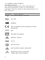
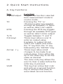
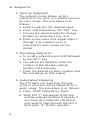
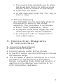
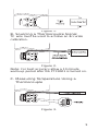
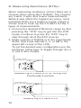
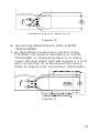
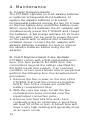
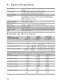
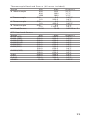
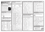
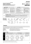
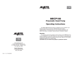
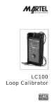
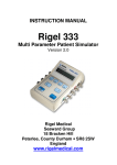
PTC8001
Temperature
Calibrator
Table of Contents
1. Introduction . . . . . . . . . . . . . . . . . . . .1
1.1 Customer Service . . . . . . . . . . . . . . . .1
1.2 Standard Equipment . . . . . . . . . . . . . .1
1.3 Safety Information . . . . . . . . . . . . . . . .2
2. Quick Start Instructions
A. Key Functions . . . . . . . . . . . . . . . . . . . .5
B. Setpoints . . . . . . . . . . . . . . . . . . . . . . .6
3. Connection Diagrams & Instructions
A. Sourcing Resistance . . . . . . . . . . . . . . .7
B. Sourcing a Thermocouple Signal . . . . .9
C. Measuring Temperature Using a
Thermocouple . . . . . . . . . . . . . . . . . . .9
D. Measuring Resistance (RTDs) . . . . . . .10
E. Sourcing Resistance (RTDs) . . . . . . . .11
4. Maintenance
A. Power Requirements . . . . . . . . . . . . .12
B. Field Replacement Fuse Update . . . . .12
C. Calibration . . . . . . . . . . . . . . . . . . . . .13
5. Specifications . . . . . . . . . . . . . . . . . . .14
6. Warranty . . . . . . . . . . . . . . . . . . . . . . .16
PTC8001
1. Introduction
The PTC8001 is designed to be a versatile,
easy to use temperature calibrator with a simple
user interface. The following instructions will
allow the user to begin simple calibration tasks
by learning the basic operation of the keys and
their functions.
1.1 Customer Service
Corporate Office:
www.martelcorp.com
e-mail: [email protected]
Tel: (603) 434-8179 800-821-0023
Fax: (603) 434-1653
Martel Electronics
PO Box 770
1F Commons Drive
Londonderry, NH 03053
1.2 Standard Equipment
Check to see if your calibrator is complete.
It should include:
Calibrator, Instruction Manual, Test Leads,
Rubber Boot, NIST Certificate
1
1.3 Safety information
Symbols Used
The following table lists the International
Electrical Symbols. Some or all of these
symbols may be used on the instrument or in
this manual.
Symbol
Description
AC (Alternating Current)
AC-DC
Battery
CE Complies with European Union
Directives
DC
Double Insulated
Electric Shock
Fuse
PE Ground
Hot Surface (Burn Hazard)
Read the User’s Manual
(Important Information)
2
Off
On
Canadian Standards Association
The following definitions apply to the terms
“Warning” and “Caution”.
• “Warning” identifies conditions and actions
that may pose hazards to the user.
• “Caution” identifies conditions and actions
that may damage the instrument being used.
Use the calibrator only as specified in this
manual, otherwise injury and damage to the
calibrator may occur.
Warning
To avoid possible electric shock or
personal injury:
• Do not apply more than the rated voltage.
See specifications for supported ranges.
• Follow all equipment safety procedures.
• Do not use the calibrator if it is damaged.
Before you use the calibrator, inspect the
case. Look for cracks or missing plastic. Pay
particular attention to the insulation
surrounding the connectors.
• Select the proper function and range for your
measurement.
• Make sure the battery cover is closed and
latched before you operate the calibrator.
3
• Remove test leads from the calibrator before
you open the battery door.
• Inspect the test leads for damaged insulation
or exposed metal. Check test leads continuity.
Replace damaged test leads before you use
the calibrator.
• Do not use the calibrator if it operates
abnormally. Protection may be impaired.
When in doubt, have the calibrator serviced.
• Do not operate the calibrator around
explosive gas, vapor, or dust.
• Disconnect test leads before changing to
another measure or source function.
• When servicing the calibrator, use only
specified replacement parts.
• To avoid false readings, which could lead to
possible electric shock or personal injury,
replace the battery as soon as the battery
indicator appears.
Caution
To avoid possible damage to calibrator or
to equipment under test:
• Disconnect the power and discharge all highvoltage capacitors before testing resistance
or continuity.
• Use the proper jacks, function, and range for
your measurement or sourcing application.
4
2. Quick Start Instructions
A. Key Functions
Key
Function
Input/Output
Toggles the function selected
from measurement mode to
source mode.
Pressing the “TC” or
“Thermocouple” key toggles
through all available TC types
as well as direct mV output.
Pressing the RTD key toggles
through all available RTD types
as well as direct ohms output.
Toggles between °F and °C
These keys allow a user to
enter an output value.
Example: to output 20 mV
select mV output and Press
the “2” key then the “0” key
followed by the “ENTER” key.
These keys allow small
changes to be made to an
output value. Press either the
up or the down key to set the
value as desired.
The clear entry key allows the
user to clear a value before the
enter key is pressed.
This key has a blue text color
and acts as a second function
key to all keys that have an
associated second function.
TC
RTD
°F/°C
0-9 keys
Arrow ↑↓
CE
Shift
5
B. Setpoints
1. Storing Setpoints
The setpoint mode allows up to 9
setpoints to be set in non-volitile memory
for each range. The procedure is as
follows:
a. Set the output to the desired value.
b. Press shift followed by the “SET” key
c. Choose the desired setpoint storage
location by pressing a key (1-9).
d. Enter a new value and repeat steps 1
through 3 as needed, up to 9
setpoints for each range can be
stored.
2. Recalling Setpoints
a. To recall a setpoint press shift followed
by the”SPT” key.
b. You will be prompted to enter the
number of the desired setpoint
location set previously.
c. Press the desired location number and
the unit will go to that output.
3. Automated Stepping
The PTC8001 can auto-step through
some or all of the stored setpoints for a
given range. The procedure is as follows:
a. Press “Shift” followed by “Auto”.
b. “Auto SPT ?” will appear. Enter the
ending setpoint location. Example: if
you have all 9 setpoints stored but
only want to step through the first 3
then enter ”3” for this question.
6
c. The next screen prompts you to enter
the dwell time from 5 to 500 seconds.
Simply enter a number in that range.
d. Auto-step will begin.
e. To exit auto-step press the “CE” key or
enter a value.
4. Manual Stepping
The PTC8001 can be manually stepped
through all or some of the stored
setpoints. The procedure is as follows:
a. Press “Shift” followed by “Man”
b. Using the arrow keys, toggle up and
down through the stored setpoints.
c. To exit press “CE” or simply enter a
new output value.
3. Connection Diagrams
& Instructions
A. Sourcing Resistance
1. Select the RTD mode.
2. Connect device under test as shown.
3. In the RTD mode, use the RTD key to choose
the desired range.
4. The PTC8001 is able to handle up to a 3 mA
excitation on the Resistance Simulation
Range. Exceeding these limits will result in a
warning on the display. See Section E. for
RTD Transmitter calibration.
7
8
Figure 1.
B. Sourcing a Thermocouple Signal
TC wire must be used to achieve an accurate
calibration.
Figure 2.
Note: For best accuracy allow a 10 minute
warm-up period after the PTC8001 is turned on.
C. Measuring Temperature Using a
Thermocouple
Figure 3.
9
D. Measuring Resistance (RTDs)
When measuring resistance (ohms) there are 3
choices when using the PTC8001. The choices
are 2-wire, 3-wire, and 4-wire measurements.
While 4-wire offers the highest accuracy, most
industrial RTDs are a balance 3-wire. Figure 4
shows how to hook up the PTC8001 for the 3
types of measurements.
1. Choose the desired RTD/ohms range by first
pressing the “RTD” key to get into the RTD
mode. Continue to press the “RTD” key to
step through all of the RTD choices.
2. Make sure the PTC8001 is in the Input Mode
(Note: that it will indicate 2, 3, or 4W in the
upper left corner of the LCD).
To set the desired wire configuration use the
Up/Down arrow keys to toggle through the 2,
3, and 4 wire modes.
Measuring a 2 Wire RTD or Using the
Continuity Function
Measuring a 3 Wire RTD
10
Measuring a 4 Wire RTD
Figure 4.
E. Sourcing Resistance Into a RTD
Transmitter
1. As described previously in section A the
PTC8001 can source resistance in a RTD
Transmitter or measuring device. In many
cases the unit under test will require a 3 or 4
wire connection to achieve best accuracy.
Refer to Figure 5 for connection information.
Figure 5.
11
4. Maintenance
A. Power Requirements
The PTC8001 operates on 4 AA alkaline batteries
or optional rechargeable Ni-Cd batteries. To
replace the alkaline batteries or to install
rechargeable batteries remove the two (2) screws
on the rear battery door and lift the battery cover.
When using Ni-Cd batteries the AC adapter will
simultaneously power the PTC8001 and charge
the batteries. A full charge will take 10-12 hours.
The AC adapter can be used to power the unit
on the bench with or without Ni-Cd batteries
installed. Never connect the AC adapter with
alkaline batteries installed, be sure to remove
the alkaline batteries before using the AC
adapter.
B. Field Replacement Fuse Update
PTC8001 comes with a field replaceable minifuse. This fuse protects the 8001 from misconnections beyond the ratings specified for
the 8001 inputs and outputs. If an overload
condition occurs and a blown fuse is suspected
perform the following fuse check/replacement
procedure:
1. Remove the four screws on the rear of the
PTC8001 that hold the enclosure together.
NOTE: Two of the screws are under the
battery compartment door.
2. With the case top open, locate the two
socketed mini fuses mounted near the
input/output connection jacks.
3. Remove one fuse at a time and check
continuity using an ohmmeter. A good fuse
will read 10 ohms or less. A blown fuse will
have a very high reading and generally show
as an open circuit.
12
4. If a blown fuse is found replace with the
enclosed spare fuse.
5. To order more fuses contact Martel
Electronics and order part number 3535039.
C. Calibration
The PTC8001 should hold its rated
specifications for a minimum of one year. Given
this, annual re-calibration is required for best
performance. See the customer service section
to contact us for re-calibration information.
13
5. Specifications
T/C Ranges:
RTD Ranges:
Ohms Ranges:
Accuracy:
RTD IEX-range:
RTD Frequency
Response:
Oper. Temp:
Storage Temp:
Power Supply:
Size:
J, K, T, E, R, S, N, B, L, U including – 10 to 70 mV
range
Pt 385 (100, 200, 500, 1000 ohms)
Pt 392, JIS, Ni 120, CU10, YSI 400
0 to 400.00 and 400.0 to 3200.0
T/C Type J: ±.3°C ±10 µV (±0.4°C total error)
RTD PT100: ±.1°C ±.075 Ω (±0.3°C total error)
Ohms (400): ±0.1 Ω
Ohms (3200): ±1.0 Ω
0.01 mA to 3 mA
10 mS – works with all pulsed XMTR’s
-10°C to 50°C
-40°C to 60°C
4 AA Alkaline Cells, 30 hours typical operating time
7.5" x 4" x 1.5"
Range & Accuracy
Range
ohms Read (low)
ohms Read (high)
Range
Ohms Source (low)
Ohms Source (high)
Min
0.00
400.0
1500.0
Min
Max
400.00
1500.0
3200.0
Max
Excitation Accuracy
Current
5.00 400.00 0.1 to 0.5 mA 0.15 ohm
5.00 400.00 0.5 to 3 mA
0.1 ohm
400.0 1500.0 0.05 to 0.8 mA 0.5 ohm
1500.0 3200.0 0.05 to 0.4 mA 1.0 ohm
Thermocouple Read and Source (All errors included)
Range
Min
Max
J Thermocouple
-200.0
0.0
0.0
1200.0
K Thermocouple
-200.0
0.0
0.0
1370.0
T Thermocouple
-200.0
0.0
0.0
400.0
E Thermocouple
-200.0
0.0
0.0
950.0
R Thermocouple
-20
0.0
0
500
500
1750
S Thermocouple
-20
0
0
500
500
1750
14
Accuracy
0.1 ohm
0.5 ohm
1.0 ohm
Accuracy
0.6°C
0.4°C
0.8°C
0.5°C
0.8°C
0.5°C
0.5°C
0.4°C
2.4°C
1.7°C
1.3°C
2.4°C
1.7°C
1.4°C
Thermocouple Read and Source (All errors included)
Range
Min
Max
B Thermocouple
600
800
800
1000
1000
1800
L Thermocouple
-200
0.0
0.0
900.0
U Thermocouple
-200
0.0
0.0
400.0
N Thermocouple
-200
0.0
0.0
1300.0
mV Read/Source
-10.00
75.00
RTD Read and Source
Range
Ni120 (672)
Pt100 (385)
Pt100(3926)
Pt100(3916)
Pt200(385)
Pt500(385)
Pt1000(385)
Cu10
Cu50
Cu100
YSI400
Min
-80.0
-200.0
-200.0
-200.0
-200.0
-200.0
500.0
-200.0
100.0
-100.0
-180.0
-180.0
15.00
Max
260.0
800.0
630.0
630.0
630.0
500.0
630.0
100.0
630.0
250.0
200.0
200.0
50.00
Accuracy
2.1°C
1.7°C
1.3°C
0.45°C
0.4°C
0.7°C
0.45°C
1.1°C
0.6°C
0.015% ± 2
Accuracy
0.2°C
0.33°C
0.3°C
0.3°C
0.8°C
0.3°C
0.4°C
0.2°C
0.3°C
2.2°C
0.5°C
0.3°C
0.05°C
15
6. Warranty
Martel Electronics Corporation warrants all
products against material defects and
workmanship for a period of twelve (12) months
after the date of shipment. Problems or defects
that arise from misuse or abuse of the
instrument are not covered. If any product is to
be returned, a “Return Material Authorization”
number must be obtained from our Customer
Service Department. This number must be
indicated on the return package as notice to
our Receiving Department to accept the
shipment. Any package not so marked will not
be accepted and will be returned to the shipper.
Martel will not be responsible for damage as a
result of poor return packaging. Out of warranty
repairs and recalibration will be subject to
specific charges. Under no circumstances will
Martel Electronics be liable for any device or
circumstance beyond the value of the product.
16
www.martelcorp.com
e-mail: [email protected]
Tel: (603) 434-8179 800-821-0023
Fax: (603) 434-1653
Martel Electronics
PO Box 770
1F Commons Drive
Londonderry, NH 03053
Rev E
0219042
7/06