1
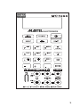
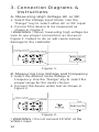
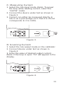
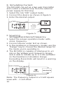
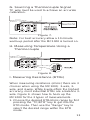
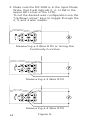
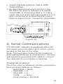
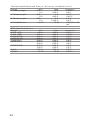
MC1000
Multi-Function
Calibrator
Table of Contents
1. Introduction
1.1 Customer Service . . . . . . . . . . . . . . . .1
1.2 Standard Equipment . . . . . . . . . . . . . .1
1.3 Safety Information . . . . . . . . . . . . . . . .2
2. Quick Start Instructions
A. Key Functions . . . . . . . . . . . . . . . . . . . .6
B. Setpoints . . . . . . . . . . . . . . . . . . . . . . .7
3. Connection Diagrams & Instructions
A. Measuring High Voltage AC or DC . . .10
B. Measuring Low Voltage
and Frequency . . . . . . . . . . . . . . . . . .10
C. Measuring Current . . . . . . . . . . . . . . .11
D. Sourcing Current . . . . . . . . . . . . . . . .11
E. Simulating Current . . . . . . . . . . . . . . .12
F. Sourcing Voltage/
Resistance/Frequency . . . . . . . . . . . . .12
G. Sourcing a Thermocouple Signal . . . .13
H. Measuring Temperature Using a
Thermocouple . . . . . . . . . . . . . . . . . .13
I. Measuring Resistance (RTDs) . . . . . . .13
J. Sourcing Resistance (RTDs) . . . . . . . .15
4. Serial Communications . . . . . . . . . . . .15
5. Maintenance
A. Power Requirements . . . . . . . . . . . . .19
B. Calibration . . . . . . . . . . . . . . . . . . . . .19
C. Field Replacement Fuse . . . . . . . . . . .19
6. Specifications . . . . . . . . . . . . . . . . . . .20
7. Warranty . . . . . . . . . . . . . . . . . . . . . . .23
MC-1000
1. Introduction
The MC1000 is designed to be a versatile, easy
to use multi-function calibrator with a simple
user interface. The following instructions will
allow the user to begin simple calibration tasks
by learning the basic operation of the keys and
their functions.
1.1 Customer Service
Corporate Office:
www.martelcorp.com
e-mail: [email protected]
Tel: (603) 434-8179 800-821-0023
Fax: (603) 434-1653
Martel Electronics
PO Box 770
1F Commons Drive
Londonderry, NH 03053
Texas Office:
www.betacalibrators.com
Tel: 800-537-2181 or (972) 241-2200
Fax: (972) 241-2200
Beta Calibrators
2309 Springdale Rd.
Farmers Branch, Texas 75234
1.2 Standard Equipment
Check to see if your calibrator is
complete. It should include:
MC1000 Calibrator, Instruction Manual, Test
Leads, Rubber Boot and NIST Certificate.
1
1.3 Safety information
Symbols Used
The following table lists the International
Electrical Symbols. Some or all of these symbols may be used on the instrument or in this
manual.
Symbol
Description
AC (Alternating Current)
AC-DC
Battery
CE Complies with European Union
Directives
DC
Double Insulated
Electric Shock
Fuse
PE Ground
Hot Surface (Burn Hazard)
Read the User’s Manual
(Important Information)
2
Off
On
Canadian Standards Association
The following definitions apply to the terms
“Warning” and “Caution”.
• “Warning” identifies conditions and actions
that may pose hazards to the user.
• “Caution” identifies conditions and actions
that may damage the instrument being used.
Use the calibrator only as specified in this manual, otherwise injury and damage to the calibrator may occur.
Warning
To avoid possible electric shock or
personal injury:
• Do not apply more than the rated voltage.
See specifications for supported ranges.
• Follow all equipment safety procedures.
• Never touch the probe to a voltage source
when the test leads are plugged into the current terminals.
• Do not use the calibrator if it is damaged.
Before you use the calibrator, inspect the
case. Look for cracks or missing plastic. Pay
particular attention to the insulation surrounding the connectors.
• Select the proper function and range for your
measurement.
• Make sure the battery cover is closed and
latched before you operate the calibrator.
3
• Remove test leads from the calibrator before
you open the battery door.
• Inspect the test leads for damaged insulation
or exposed metal. Check test leads continuity.
Replace damaged test leads before you use
the calibrator.
• When using the probes, keep your fingers
away from the probe contacts. Keep your fingers behind the finger guards on the probes.
• Connect the common test lead before you
connect the live test lead. When you disconnect test leads, disconnect the live test lead
first.
• Do not use the calibrator if it operates abnormally. Protection may be impaired. When in
doubt, have the calibrator serviced.
• Do not operate the calibrator around explosive gas, vapor, or dust.
• When using a pressure module, make sure
the process pressure line is shut off and
depressurized before you connect it or disconnect it from the pressure module.
• Disconnect test leads before changing to
another measure or source function.
• When servicing the calibrator, use only specified replacement parts.
• To avoid false readings, which could lead to
possible electric shock or personal injury,
replace the battery as soon as the battery
indicator appears.
• To avoid a violent release of pressure in a
pressurized system, shut off the valve and
slowly bleed off the pressure before you
attach the pressure module to the pressure
line.
4
Caution
To avoid possible damage to calibrator or
to equipment under test:
• Disconnect the power and discharge all highvoltage capacitors before testing resistance
or continuity.
• Use the proper jacks, function, and range for
your measurement or sourcing application.
• To avoid mechanically damaging the pressure
module, never apply more than 10 ft-lb. of
torque between the pressure module fittings,
or between the fittings an the body of the
module.
• To avoid damaging the pressure module from
overpressure, never apply pressure above the
rated maximum printed on the module.
• To avoid damaging the pressure module from
corrosion, use it only with specified materials.
Refer to the pressure module documentation
for material compatibility.
5
2. Quick Start Instructions
A. Key Functions
Key
Input/Output
Function
Toggles the function selected
from measurement mode to
source mode.
V/mA/Hz
Selects between volts, milliamps, and frequency modes
TC/RTD
Selects between temperature
modes either T/C or RTD.
Ohms and mV ranges are also
included in these functions.
Ranges/Units This key toggles through all
the ranges for a chosen function. Example: If T/C mode is
selected the Range key toggles through the ranges J, K,
T, E, etc.
0-9 keys
These keys allow a user to
enter an output value.
Example: to output 20 mA
select mA output and Press
the “2” key then the “0” key
followed by the “ENTER” key.
Arrow ↑↓
These keys allow small
changes to be made to an output value. Press either the up
or the down arrow key to set
the value as desired.
CE
The clear entry key allows the
user to clear a value before the
enter key is pressed.
Shift
This key has a blue text color
6
and acts as a second function
key to all keys that have an
associated second function.
Features such as setpoints,
°F/°C, backlight and external
pressure module activation all
use the Shift key.
B. Setpoints
1. Storing Setpoints
The setpoint mode allows up to 9 setpoints to be stored in non-volitile memory for each range. The procedure is as
follows:
a. Set the output to the desired value.
b. Press shift followed by the “SET” key.
c. Choose the desired setpoint storage
location by pressing a key (1-9).
d. Enter a new value and repeat steps 1
thru 3 as needed, up to 9 setpoints for
each range can be stored.
2. Recalling Setpoints
a. To recall a setpoint, press shift followed by the”SPT” key.
b. You will be prompted to enter the
number of the desired setpoint location stored previously.
c. Press the desired location number and
the unit will go to that output.
3. Automated Stepping
The MC1000 can auto-step through
some or all of the stored setpoints for a
given range. The procedure is as follows:
a. Press “Shift” followed by auto.
b. “Auto SPT ?” will appear. Enter the
7
ending setpoint location. Example: if
you have all 9 setpoints stored but
only want to step through the first 3
then enter “3” for this question.
c. The next screen prompts you to enter
the dwell time from 5 to 500 seconds.
Simply enter a number in that range.
Then press the “Enter” key.
d. Auto-step will begin.
e. To exit auto-step press “CE” key or
enter a value.
4. Manual Stepping
The MC1000 can be manually stepped
through all or some of the stored setpoints. The procedure is as follows:
a. Press “Shift” followed by “Man”.
b. Using the arrow keys, toggle up and
down through the stored setpoints.
c. To exit press CE or simply enter a new
output value.
5. Pressure Module Interface
The MC1000 has the capability to interface with a family of pressure modules
available from Martel. The procedure is
as follows:
a. Connect the pressure module to the
15 pin “D” connector on top of the
MC1000.
b. Press “Shift” followed by the “
”
key.
c. Always zero the pressure module
before starting a calibration. Press
“Shift” followed by the “Zero” key.
Note: More detailed information can be found with
the instructions packaged with each module.
8
9
3. Connection Diagrams &
Instructions
A. Measuring High Voltage AC or DC
1. Select the Voltage Input Mode. Use the
“Range” key to select either AC or DC input.
2. Connect the device to be measured as
shown in Figure 1.
! WARNING ! When measuring high voltage be
sure to use proper connections as shown in
Figure 1. Failure to do so will cause serious
damage to the calibrator.
Figure 1.
B. Measuring Low Voltage and Frequency
1. Select the desired mode Voltage or
Frequency. Use the “Range” key to select the
proper range for the mode chosen.
2. Connect the device under test as shown in
Figure 2.
Figure 2.
! WARNING ! Do not exceed 20 VDC at the
V/Ω/Hz input.
10
C. Measuring Current
1. Select the mA input mode. Note: To power
the loop while reading current, select the
“mAPW” mode.
2. Connect the device under test as shown in
Figure 3.
3. Current can either be measured directly in
mA or as a percentage such that 4 to 20 mA
corresponds to 0 to 100%.
Figure 3.
D. Sourcing Current
1. Select the mA output mode on the calibrator.
2. Connect device under test as shown in
Figure 4.
3. Enter the value of desired output current.
Note: If the loop is open “OL” will appear in the
display.
Figure 4.
11
E. Simulating Current
The MC1000 can act as a two-wire transmitter
and control a 4-20mA loop from the external
power supply for that loop.
1. Select the mA “2W” output mode.
2. Connect the device as shown in figure 5.
3. Enter the desired output.
Figure 5.
F. Sourcing
Voltage/Resistance/Frequency
1. Select the proper operation mode: volts,
ohms, frequency.
2. Connect device under test as shown.
3. In the resistance or frequency modes use the
“Range” key to choose the desired range for
the mode you’re operating in.
4. The MC1000 is capable of driving up to ±1
mA on the Voltage and Frequency ranges
and is able to handle up to a 3 mA excitation
on the Resistance Simulation Range.
Exceeding these limits will result in a warning
on the display.
Figure 6.
Note: The frequency output is a 5 Volt square
wave with –.1 volt offset
12
G. Sourcing a Thermocouple Signal
TC wire must be used to achieve an accurate
calibration.
Figure 7.
Note: For best accuracy allow a 10 minute
warm-up period after the MC1000 is turned on.
H. Measuring Temperature Using a
Thermocouple
Figure 8.
I. Measuring Resistance (RTDs)
When measuring resistance (ohms) there are 3
choices when using the MC1000; 2-wire, 3wire, and 4-wire. While 4-wire offers the highest
accuracy, most industrial RTDs are a balance 3wire. Figure 9. shows how to hook up the
MC1000 for the 3 types of measurements.
1. Choose the desired RTD/ohms range by first
pressing the “TC/RTD” key to get into the
RTD mode. Then use the “Range” key to
select the desired range within the RTD
mode.
13
2. Make sure the MC1000 is in the Input Mode
(Note: that it will indicate 2, 3, or 4W in the
upper left corner of the LCD).
To set the desired wire configuration use the
“Up/Down arrow” keys to toggle through the
2, 3, and 4 wire modes.
Measuring a 2 Wire RTD or Using the
Continuity Function
Measuring a 3 Wire RTD
Measuring a 4 Wire RTD
14
Figure 9.
J. Sourcing Resistance Into a RTD
Transmitter
1. As described previously in section F the
MC1000 can source resistance in a RTD
Transmitter or measuring device. In many
cases the unit under test will require a 3 or 4
wire connection to achieve best accuracy.
Refer to Figure 10 for connection information.
Figure 10.
4. Serial Communications
The MC1000 calibrator is equipped with a RS232 serial communications port, which can be
located on the top of the case.
Note: This jack was chosen for its small size
and sealing ability. As a consequence, the user
will require a special RS-232 cable to connect
the calibrator to a computer or terminal.
Communication
Once the cable is attached, set the communications program settings as follows:
Baud Rate = 9600
Data Bits = 8
Stop Bits = 1
Parity
= None
Flow Control = Xon/Xoff
15
The MC1000 calibrator can be used with
virtually any terminal emulation software. (i.e.
Procomm or HyperTerminal)
When connected properly, data will be transmitted as soon as the calibrator is turned on. The
data transmitted to the terminal or computer will
mirror that sent to the calibrators LCD display
and will be updated approximately every 0.4
seconds.
Serial Communications
Procedure for HyperTerminal
Program
1. From the Windows® ‘95 main menu, click on
“Start”.
2. Click on “Programs”.
3. Under the category “Accessories”, click on
“Hyper Terminal”.
4. Double click on “Hypertrm.exe”.
5. Next appears a screen labeled: CONNECTION DESCRIPTION. In the box titled: Name,
enter a name for your program settings...
example: “MC Connection”. In a box titled:
Icon, click on the icon which resembles a
phone and some papers in front of a bulletin
board. (Note: this icon lies between icons
containing a GE logo on the left and an icon
containing a red umbrella on the right.) Click
on the OK box to accept these entries.
6. Next appears a screen labeled: PHONE
NUMBER. In the box titled: Connect Using,
select the serial port that corresponds to the
computer serial port that you’ll be using to
communicate to the MC1000 calibrator. Click
on the OK box to accept this entry.
7. Next appears a screen labeled: COM X
PROPERTIES (where X corresponds to the
serial port selected in step #6). Enter port
16
settings as follows:
(A.)
Bits per second:
9600
(B.)
Data bits:
8
(C.)
Parity: None
(D.)
Stop Bits:
1
(E.)
Flow Control:
Xon/Xoff
Click OK box to accept these entries.
8. Hook up the MC1000 calibrator to the PC utilizing the special Martel Electronics RS-232
cable as follows:
(A.) Plug the 9 pin connector end of the
cable to the appropriate serial port
on the computer.
(B.) With the MC1000 calibrator
switched off, plug the other end of
the cableplug the other end of the
cable (male phono jack) into the
port labeled “RS-232” on the top of
the MC1000 calibrator.
9. Power up the MC1000 calibrator per the
appropriate instruction manual. The computer
screen should now be displaying data being
sent directly from the MC1000 calibrator.
Note: You may wish to save these settings
when exiting HyperTerminal. If so, click on the
OK box when prompted “Do you want to save
X?”, where X corresponds to the name entered
in Step #5.
Computer Controlled Operation
The MC1000 calibrator can be operated remotely via a computer or terminal. When connected
to a computer, via the RS-232 serial data port
and appropriate cabling, the user may control
the calibrator functions remotely by utilizing simple computer keyboard commands.
The following chart details which computer keys
control which MC1000 calibrator functions:
17
Serial Input
A
a
I
i
V
v
M
m
E
e
K
k
H
h
P
p
W
X
Y
T
t
C
F
R
r
0-9
-,.
<CR>
D
d
Description
mA measurement
mA source
mA loop
mA 2W Sim
Volts measurement
Volts source
mV measurement
mV source
HVAC measure
HVDC measure
Khz measurement
Khz source
Hz measurement
Hz source
CPM measurement
CPM source
2-wire measurement (Ohms and RTDs)
3-wire measurement (Ohms and RTDs)
4-wire measurement (Ohms and RTDs)
Thermocouple measurement (default Type J) use
"S" command to select sensor type
Thermocouple source (default Type J) use "S"
command to select sensor type
Selects Centigrade ( T/C - RTD )
Selects Fahrenheit ( T/C - RTD )
RTD measurement mode (default Pt100 385) use
"S" command to select sensor type
RTD measurement mode (default Pt100 385) use
"S" command to select sensor type
Enter a source value using ascii characters
0,1,2,..,9,-,.terminated by <CR>(carriage
return)
Single Broadcast of most recent display value and
units
Single Broadcast of most recent display value
"S" Commands Select
Sensor Type
Serial Input
S
18
Selection Entry
No.
T/C Type
1
J
2
K
3
T
4
E
5
R
Description
RTD Type
Pt100 (3926)
Pt100 (385)
Pt100 (3916)
Cu10
Pt200 (385)
Serial Input
S
Selection Entry
No.
T/C Type
6
S
7
B
8
L
9
U
A
N
B
mV
Description
RTD Type
Pt500 (385)
Pt1000 (385)
NI120
YSI
OHMS
® Microsoft, Windows, Windows NT, and MS-DOS are registered
trademarks of Microsoft Corporation. All other product names or
services identified throughout this manual are registered trademarks or trademarks of their respective companies.
5. Maintenance
A. Power Requirements
The MC1000 operates on 4 AA alkaline batteries
only.
B. Calibration
The MC1000 should hold its rated specifications for a minimum of one year. Given this,
annual re-calibration is required for best performance. See the customer service section (7.)
to contact Martel for re-calibration information.
C. Field Replacement Fuse
MC1000 comes with a field replaceable minifuse. This fuse protects the MC1000 inputs and
outputs. If an overload condition occurs and a
blown fuse is suspected perform the following
fuse check/replacement procedure:
1. Remove the four screws on the rear of the
MC1000 that hold the enclosure together.
NOTE: Two of the screws are under the battery compartment door.
2. With the case top open, locate the two socketed mini fuses mounted near the input/output connection jacks.
19
3. Remove one fuse at a time and check continuity using an ohmmeter. A good fuse will
read 10 ohms or less. A blown fuse will have
a very high reading and generally show as
an open circuit.
4. If a blown fuse is found replace with the
enclosed spare fuse.
5. To order more fuses contact Martel
Electronics and order part no. 3535039.
6. Specifications
Pressure
Ranges:
T/C Ranges:
RTD Ranges:
Ohms Ranges:
mA Range:
Voltage:
Frequency:
Continuity:
Accuracy:
mA Compliance:
Voltage Drive
Capability:
RTD IEX-range:
RTD Frequency
Response:
Oper. Temp:
Storage Temp:
Loop Power:
Size:
20
Module Dependent. Operates with Fluke 700 Series
Modules
J, K, T, E, R, S, N, B, L, U including – 10 to 70mV
Pt 385 (100, 200, 500, 1000 ohms)
Pt 392, JIS, Ni120, CU10, YSI400
0 to 400.00 and 400.0 to 3200.0
0 to 24.000 mA
(Low) Input 0-20.000 V, Output 0-20.000 V
(High) Input only 0-250 VDC or VAC
Measure
Source
CPM
2.0-1000.0 0.0-1000.0
Hz
0-1000
0.0-1000.0
kHz
1.0-10.0
0.0-10.00
0 to 400.0 ohms, audible tone when under 10 ohms
T/C Type J: ±.3°C ±10 µV (±0.4°C total error)
RTD PT100: ±.1°C ±.075 Ω (±0.3°C total error)
Ohms (400): ±0.1 Ω
Ohms (3200): ±1.0 Ω
Up to 1000 Ω load
1 mA
0.01 mA to 3 mA
10 mS – works with all pulsed XMTR’s
-10°C to 50°C
-40°C to 60°C
4 AA alkaline batteries, 25 hours typical operating
time
7.5" x 4" x 1.5"
Range & Accuracy
Range
Min
Max
0.000
0.0
0.0
0.000
-10.00
-10.00
20.000
250.0
250.0
20.000
75.00
75.00
Accuracy
(% of reading ±
counts)
0.015% ±2
0.05% ±2
0.5% ±2
0.015% ±2
0.015% ±2
0.015% ±2
mA Read
mA Source
0.000
0.000
24.000
24.000
0.015% ± 2
0.015% ± 2
CPM Source
Hz Source
2.0
1
1000.0
1000
0.05%
0.05%
KHz Source
CPM Read
Hz Read
KHz Read
1.0
0.0
0.0
0.00
10.0
1000.0
1000.0
10.00
0.25%
0.05% ± 1
0.05% ± 1
0.05% ± 1
Min
0.00
400.0
1500.1
Max
400.00
1500.0
3200.0
V Read (low)
VDC Read (high)
VAC Read (high)
V Source
mV Read
mV Source
Range
Ohms Read (low)
Ohms Read (high)
Range
Min
Max
Accuracy
0.1 ohm
0.5 ohm
1.0 ohm
Excitation
Current
Ohms Source (low)
5.00 400.00 0.1 to 0.5 mA
5.00 400.00 0.5 to 3 mA
Ohms Source (high) 400.0 1500.0 0.05 to 0.8 mA
1500.0 3200.0 0.05 to 0.4 mA
Thermocouple Read and Source (All errors included)
Range
Min
Max
J Thermocouple
-200.0
0.0
0.0
1200.0
K Thermocouple
-200.0
0.0
0.0
1370.0
T Thermocouple
-200.0
0.0
0.0
400.0
E Thermocouple
-200.0
0.0
0.0
950.0
R Thermocouple
-20
0.0
0
500
500
1750
S Thermocouple
-20
0
0
500
500
1750
B Thermocouple
600
800
800
1000
1000
1800
Accuracy
0.15 ohm
0.1 ohm
0.5 ohm
1.0 ohm
Accuracy
0.6°C
0.4°C
0.8°C
0.5°C
0.8°C
0.5°C
0.5°C
0.4°C
2.49°C
1.7°C
1.3°C
2.4°C
1.7°C
1.4°C
2.1°C
1.7°C
1.3°C
21
Thermocouple Read and Source (All errors included) (cont.)
Range
Min
Max
Accuracy
L Thermocouple
-200
0.0
0.45°C
0.0
900.0
0.4°C
U Thermocouple
-200
0.0
0.7°C
0.0
400.0
0.45°C
N Thermocouple
-200
0.0
1.1°C
0.0
1300.0
0.6°C
mV Read/Source
-10.00
75.00
0.015% ±.02
mV
RTD Read and Source
Range
Ni120 (672)
Pt100 (385)
Pt100(3926)
Pt100(3916)
Pt200(385)
Pt500(385)
Pt1000(385)
Cu10
YSI400
22
Min
-80.0
-200.0
-200.0
-200.0
-200.0
-200.0
500.0
-200.0
100.0
-100.0
15.00
Max
260.0
800.0
630.0
630.0
630.0
500.0
630.0
100.0
630.0
250.0
50.00
Accuracy
0.2°C
0.33°C
0.3°C
0.3°C
0.8°C
0.3°C
0.4°C
0.2°C
0.3°C
2.2°C
0.05°C
7. Warranty
Martel Electronics Corporation warrants all
products against material defects and workmanship for a period of twelve (12) months
after the date of shipment. Problems or defects
that arise from misuse or abuse of the instrument are not covered. If any product is to be
returned, a “Return Material Authorization” number must be obtained from our Customer
Service Department. This number must be indicated on the return package as notice to our
Receiving Department to accept the shipment.
Any package not so marked will not be accepted and will be returned to the shipper. Martel
will not be responsible for damage as a result
of poor return packaging. Out of warranty
repairs and recalibration will be subject to specific charges. Under no circumstances will
Martel Electronics be liable for any device or
circumstance beyond the value of the product.
23
www.martelcorp.com
e-mail: [email protected]
Tel: (603) 434-8179 800-821-0023
Fax: (603) 434-1653
Martel Electronics
PO Box 770
1F Commons Drive
Londonderry, NH 03053
www.betacalibrators.com
Tel: 800-537-2181 or (972) 241-2200
Fax: (972) 241-2200
Beta Calibrators
2309 Springdale Rd.
Farmers Branch, Texas 75234
Rev D
1/05
0219041

![MC1000 Quick Start Guide [Spanish]](http://vs1.manualzilla.com/store/data/006172196_1-eb8d7c45a657c85a50c3c04048a0df41-150x150.png)