1
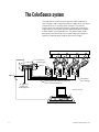
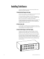
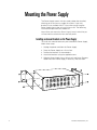
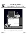
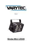
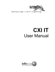
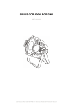
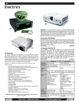
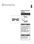
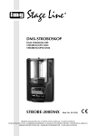
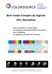
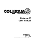
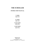
User Manual
Color Changer and Power Supply
User Manual
Software version 1.011
Contents
Introduction ..................................................................................... 5
The ColorSource System ................................................................ 6
Using ColorSource .......................................................................... 7
ColorSource components ................................................................ 8
Color Changer ........................................................................... 8
Gelstring .................................................................................... 8
Power Supply ............................................................................ 9
Cables ....................................................................................... 9
Installing ColorSource ................................................................... 10
Mounting the Power Supply ......................................................... 12
Installing rack mount brackets on the Power Supply .............. 12
Installing pipe mount brackets on the Power Supply .............. 13
Replacing a gelstring ..................................................................... 14
Replacing the mounting plate ....................................................... 16
Specifications ................................................................................ 17
Parts list ........................................................................................ 18
Custom gelstring order form ......................................................... 19
4
Electronic Theatre Controls, Inc.
Introduction
The ColorSource system includes a scrolling Color Changer and
Power Supply. Its ten-color capacity and DMX512 compatibility
makes it economical and versatile, particularly for designers with
limited budget and space. The lightweight Color Changer slides
easily into the gel frame holder of the light fixture and the compact
12 output Power Supply attaches easily to the truss of the lighting
rig or in a 19 inch rack.
This manual gives step-by-step instructions for preparation, setup
and operation of the ColorSource Color Changer and ColorSource
Power Supply.
The Color Changer is delivered to you with your choice of gelstring
and mounting plate installed. If you need to change gelstrings or
mounting plates, instructions are included in this manual.
ColorSource User Manual
5
The ColorSource system
The ColorSource system consists of one or more ColorSource
Color Changers and a ColorSource Power Supply which can power
and control up to 12 scrolling Color Changers. The DMX512
control signal from the lighting board is connected to the power
supply and can continue on to more ColorSource power supplies
or other DMX512 controlled devices. The power supply sends
both power and control signal on a single cable, eliminating the
need for a separate power cable for each color changer.
ColorSource
Power Supply
T
Power
COLORSOURCE OUTPU
DMX IN
1
2
DMX OUT
7
8
4
5
6
3
10
11
12
9
AC POWER
DMX512
Power/signal cable (100 feet maximum)
Up to 12 per Power Supply
ColorSource
Color Changer
To additional
ColorSource
Power Supplies
Control console
6
Electronic Theatre Controls, Inc.
Using ColorSource
The Color Changer sets its frame position according to the DMX512 level
it receives from the control console using the channels set on the Power
Supply. The following chart shows the level settings that correspond with
each frame position, and the color of that frame, if you are using the
standard ColorSource gelstring. If you are using a custom gelstring, of
course, the colors are different, but the channels and frames are the
same.
Channel Frame
Standard
level
position color
0
11
22
33
44
55
66
77
88
99
Frame 1
Frame 2
Frame 3
Frame 4
Frame 5
Frame 6
Frame 7
Frame 8
Frame 9
Frame 10
Clear
Antique Rose
Chorus Pink
Magenta
Light Red
Deep Amber
Mellow Yellow
Light Green
Aztec Blue
Light Purple
If you send a channel level that is between the values shown, you can
create split frame effects. For example, if you send a level of 50, the
Color Changer positions the gelstring halfway between frame 5 and
frame 6 creating a blend of the two colors.
ColorSource User Manual
7
ColorSource components
Color Changer
The ColorSource Color Changer holds a ten color gelstring. A
signal from the power supply controls the position of the gelstring.
Low voltage AC from the Power Supply provides power to the
Color Changer. This control signal and the low voltage AC power
are both supplied by the single cable connecting the Color
Changer to the Power Supply.
A fan in the base of the Color Changer runs whenever the Color
Changer is connected to the Power Supply. This protects the
gelstring from overheating. The fan is most effective when the
Color Changer is oriented with the fan directing air up.
Gelstring
The gelstring is a series of ten precisely cut colored gel frames,
joined together side-by-side to create a sequence of colors. Two
additional gels at each end of the gelstring are called the leader
and the trailer and are five inches wide to allow for proper attachment to the rollers.
If you need to replace the gelstring in your Color Changer, the
ColorSource system’s Autoload feature walks you through the
simple gelstring loading procedure. See page 15.
Note: Gelstrings may be ordered from either ETC or ColorExpress
by Wybron. See page 19 for an order form
8
Electronic Theatre Controls, Inc.
Power Supply
The Power Supply converts the DMX512 signal level into a control
signal and sends this control signal along with low voltage AC on
one cable to power each color changer. The Power Supply features a DMX512 bypass relay to pass the DMX512 signal to the
DMX512 output connector in the event of loss of power supply
AC power.
The Power Supply features a liquid crystal display (LCD) that lets
you select between the Channel display and the Autoload display.
When you turn it on, the Power Supply displays a scrolling introduction including the Power Supply software version, then goes to
the Channel display.
The Channel display shows the 12 DMX512 channels and the
message DMX OK or NO DMX. This indicates whether or not the
Power Supply is connected to a DMX512 source.
Press [Menu] to switch from the Channel display to the Autoload
display.The Autoload display walks you through the process of
loading a gelstring onto the Color Changer’s rollers and testing it.
001--012 DMX OK
MENU
[–]
NO
[+]
YES
POWER
Power Supply
display
Power Supply
controls
Cables
A ColorSource cable connects each Color Changer to one of the
12 Power Supply outputs and provides the Color Changer with
power and control signal. A DMX512 cable connects the Power
Supply to a DMX512 signal source, usually a lighting control
console
ColorSource User Manual
9
Installing ColorSource
To get your ColorSource system up and running, follow these
hookup and checkout procedures.
1. Attach the Color Changer to the lamp
Slide the Color Changer’s mounting plate into the gel frame holder
of your lamp and lock the gel frame retention clip.
If the mounting plate installed on your Color Changer doesn’t fit
the fixture, you may replace it with a differently sized plate. See
page 16 for information on changing mounting plates.
The mounting plate allows you to position the Color Changer with
the gelstring rolling either horizontally or vertically. However,
ColorSource operates most effectively with the fan blowing air
vertically (as hot air naturally rises).
2. Attach safety cable
A safety cable is attached to the back and right-hand side of the
Color Changer. Run this cable around the pipe or truss from which
you hang the light fixture and clip it to itself.
3. Connect Color Changers to the Power Supply
Connect the Color Changers to the Power Supply using the
supplied 6-pin power/signal cable. The connectors are on the
bottom of the Color Changer and the back of the Power Supply.
Note: Both power and signal are supplied to the Color Changers
by the same cable. The Color Changer connected to output
connector 1 operates on the first of the 12 DMX512 channels, the
color changer connected to output connector 2 operates on the
second, and so on. Only one scroller may be connected to each
output connector.
TPUT
COLORSOURCE OU
10
5
6
2
4
1
3
DMX IN
9
11
12
AUTO LOAD
DMX OUT
8
10
7
AC POWER
Electronic Theatre Controls, Inc.
4. Connect Power Supply to AC power
Plug the pronged end of the AC power cord into a 115 VAC (50/
60Hz) non-dimmed circuit. Plug the other end into the connector
labeled AC Power on the back of the Power Supply. All connected
Color Changers position their gelstrings to frame 1.
Warning: Do not power the unit from a dimmer. Severe damage
will result, and is not covered by product warranty.
Note: Avoid line voltages lower than 105 VAC or higher than 125
VAC as the system may not run properly outside of these limits.
6. Connect and set the DMX512 source
001--012 NO DMX
Before you connect the DMX512 source, the Power Supply
display reads NO DMX. Connect the DMX512 signal source to the
DMX512 input connector on the Power Supply using standard
DMX512 cable. The display reads DMX OK and the Color Changers position their gelstrings according to their respective DMX512
signal levels.
7. Set the Power Supply DMX512 channels
001--012 DMX OK
Each Power Supply is assigned a range of 12 DMX512 channels,
corresponding to its 12 outputs. The Power Supply’s Channel
display shows the range of channels. To adjust the range of
channels, press [+] or [–] while in the Channel display.
Hint: Hold down [+] or [–] to scroll through the channels quickly
Note: The Power Supply automatically senses the number of
dimmers transmitted by the lighting console and won’t allow you
to set the DMX512 channels outside this range.
ColorSource User Manual
11
Mounting the Power Supply
The Power Supply comes with four sturdy rubber feet installed,
allowing you to set it on any stable flat surface. If you wish,
bracket kits are available from ETC that allow you to hang the
Power Supply from a pipe, or install it into a rack. The following
instructions explain how to use both kits.
Note: When you mount the Power Supply, keep in mind that you
will need access to both the front and rear panels.
Installing rack mount brackets on the Power Supply
To install rack mount brackets on your ColorSource Power Supply,
follow these steps.
1. Unplug the power cord from the Power Supply.
2. Place the Power Supply on a flat surface.
3. Position the brackets as shown below.
4. Attach the brackets using the supplied screws.
5. Slide the Power Supply into a 19-inch rack and fasten. Remove
rubber feet from Power Supply if necessary and save them.
TPUT
COLORSOURCE OU
DMX IN
DMX OUT
12
6
3
5
2
4
1
11
12
AUTO LOAD
7
9
10
8
AC POWER
Electronic Theatre Controls, Inc.
Installing pipe mount brackets on the Power Supply
To install pipe mount brackets on your ColorSource Power Supply,
follow these steps.
1. Unplug the power cord from the Power Supply.
2. Place the Power Supply upside down on a flat surface.
3. Use a Phillips head screwdriver to remove the rubber feet from
each of the four corners. Store the feet somewhere safe.
4. Position the brackets as shown below.
5. Attach the brackets using the screws supplied.
6. Mount the Power Supply on the desired pipe using the bolts
provided as shown below.
7. Wrap the safety cable around the pipe and clip it to itself.
7
DMX IN
1
8
9
2
4
11
5
12
AUTO LOAD
6
OUTPUT
COL
OR
SOU
RCE
OU
TPU
T
COLORSOURCE
3
10
ColorSource User Manual
13
Replacing a gelstring
Thumbscrews
At some point you may find that you need to replace the gelstring
in your Color Changer, either because the old one wears out, or
because you want a different selection of colors. ColorSource’s
Autoload procedure makes this easy by walking you through the
procedure, step by step.
Note: The gelstring must be ten frames long for proper operation.
If a frame is damaged, do not remove a frame and splice the
gelstring. Replace the gelstring.
Note: You may install a gelstring with or without a DMX512
source connected to the Power Supply.
Warning: Do not force the rollers to turn when turning them by
hand. If they do not turn easily, you have not disconnected the
DMX512 cable, and should do so immediately.
To replace a gelstring, follow these steps. Press [Menu/No] at any
point in the process to cancel loading.
Left roller
(trailer/frame 10)
Right roller
(leader/frame 1)
Remove old gelstring
1. Place the Color Changer on a flat surface with the ColorSource
logo facing up. The power/signal cable connector should be
facing you, with the cable connecting it to output 12 on the
Power Supply (labeled AUTOLOAD).
2. Unscrew the two thumbscrews at the top right and left
corners of the front panel as shown in first picture at left. Lift
the panel by the screws and remove it from the Color Changer.
3. If you are connected to a DMX512 source, set the gelstring to
the DMX512 = 100 position.
4. Disconnect power cable from Color Changer.
5. Gently roll the gelstring all the way onto the right roller, exposing the clear trailer taped on the left roller.
6. Untape trailer from left roller. Remove tape from trailer and
save it.
7. Roll gelstring into a tube, slowly rolling it off the right roller.
8. When you reach the clear leader, untape it from the roller.
Remove the gaffer’s tape from leader and save it. If you expect
to reuse the old gelstring, reroll it in the opposite direction, so
the trailer is on the outside.
Fan
14
Power/signal
connector
Electronic Theatre Controls, Inc.
Install new gelstring
Note: Use gaffer’s tape to attach the gelstring to the rollers. Do
not use duct tape or masking tape.
1. Press [Menu] to select LOAD GELSTRING? on the display.
LOAD GELSTRING?
2. Press [Yes]. The display reads OUTPUT #12 READY?
3. Reconnect the power cable to the Color Changer.
4. Press [Yes]. The rollers reset to frame 10 and the display reads
TAPE TRAILER TO LEFT ROLLER ...... DONE?
Gaffer’s tape
5. Put a strip of gaffer’s tape on the gelstring trailer. Holding the
trailer, let the rest of the roll hang off the right side of the Color
Changer.
6. Center the edge of the trailer between the two ends of the left
roller as shown to left. Tape the trailer along the top of the
roller as shown.
7. Hold the rolled gelstring loosely in your right hand and press
[Yes]. The display reads LOADING GEL and the left roller turns
to roll the gelstring onto the left roller.
8. Hold the gelstring lightly to allow it to roll uniformly onto the
roller until the display reads TENSION SPRING 2.5 TURNS
TOWARD LEFT ROLLER ...... TAPE LEADER ...... DONE?
9. Put a strip of gaffer’s tape on the gelstring leader.
10. Turn the spring roller two and a half turns to the left, then tape
the edge of the leader centered along the top of the spring
roller. The sticker at the bottom end of the roller has a black
line on it to help you judge the number of turns.
11. Replace the front panel, tightening the two screws gently.
Trailer
12. Press [Yes] when done. The display reads GEL TO ZERO?
Frame 10
13. Press [Yes]. The gelstring moves to frame 1. Check for proper
color positioning. The display reads GEL TO FULL?
14. Press [Yes]. The gelstring moves to frame 10. Check for proper
color positioning. The display reads LOAD COMPLETED?
15. Press [Yes]. The Color Changer returns to its current DMX512
level if it is connected to a DMX512 source, or to frame 1 if it
isn’t, and the Power Supply returns to the Autoload display.
16. Press [Yes] to load another gelstring, or press [No] to return to
the Channel Display screen.
17. Replace the front panel and tighten the thumbscrews securely.
The gelstring is now loaded onto the ColorSource Color Changer.
If the gelstring colors did not center properly at the zero and full
positions, remove the gelstring (see previous page) and repeat the
Autoload process until they center properly.
Note: Gel material of different thicknesses may cause slight
variation in frame positions at zero. This is normal.
ColorSource User Manual
15
Replacing the mounting plate
Top
The ColorSource Color Changer ships with your choice of available
mounting plates installed. Always use the supplied screws as they
are treated with an anti-vibration compound to keep them from
loosening.
Follow these steps to replace the mounting plate.
1. Place the Color Changer on a flat surface, with the ColorSource
logo face down.
2. Unscrew the four screws that hold the current mounting plate
on.
Note screw
positions
This mounting plate fits spotlights with a
6.25” frame size, including ETC Source
Four. Mount the plate in the orientation
shown. Note that the screws are closer
together in one direction than the other.
This mounting plate fits spotlights
with a 7.5” frame size, including
ETC Source FourPAR.
16
3. Place the replacement mounting plate on the Color Changer
aligning the screw holes properly. If you are installing the 6.25”
mounting plate, see the illustration to left for proper plate
orientation.
4. Fasten the four corners of the mounting plate to the Color
Changer using the same screws you removed in step 2.
This mounting plate fits spotlights
with a 10” frame size.
Electronic Theatre Controls, Inc.
Specifications
ColorSource gelstring
Ten frames plus leader and trailer
Working length: 100 inches
Overall length: 110 inches
End to end speed: Three seconds
Frame width: Ten inches
Frame height: 7 1/16 inches
Leader: Five inches wide
Trailer: Five inches wide
ColorSource Power Supply
12 Color Changers per power supply
12 DMX512 channels per power supply
Starting DMX512 channel range: 1 - 501
DMX512 power loss bypass relay: Yes
Voltage: 115 VAC 50/60 Hz (standard wiring),
230 VAC ±10% 50/60 Hz (via internal wire changes)
other voltages, contact Wybron
Fuse:
2 amp slow blow at 115 VAC
1 amp slow blow at 230 VAC
1 line by 16 character alphanumeric display
12 XLR 6-pin female output connectors
DMX512 connectors input: 5-pin male XLR output
5-pin female XLR
DMX512 control cable
The DMX512 control signal cable from the lighting board to the
Power Supply is a 5-conductor cable terminated with a standard
XLR 5-pin connector. Wiring pinout is specified by the USITT
DMX512/ 1990 standard.
Control signal DMX512 pinout
Pin 1 = Common
Pin 2 = Data –
Pin 3 = Data +
Pin 4 = n/c
Pin 5 = n/c
ColorSource cable pinout
XLR Pin # Wire Color Function
1
2
3
4
5
6
Black
Red
Brown
Green
White
---------
Transformer center tap
Transformer secondary
Transformer secondary
Signal ground
Signal 0 - 10 Vdc
No connection
Note: Maximum cable length of 100 feet to each ColorSource
Color Changer.
ColorSource User Manual
17
Parts list
To order additional Color Changers, accessories or parts, please contact your authorized
ETC dealer.
ColorSource Color Changer
CS .................... ColorSource Color Changer
ColorSource Color Changers are supplied with an installed ten color gelstring and a mounting plate. To specify the type of
gelstring and mounting plate to be supplied with a ColorSource Color Changer, add the following suffixes to the catalog
number. For example: CS-GS-MP75 specifies a standard gelstring and 7.5” mounting plate.
-GS .................. Standard ten color gelstring
-GSC ................ Custom ten color gelstring (Colors must be specified)
-MP65 .............. Mounting plate for spotlights with 6.25” frame size (Source Four)
-MP75 .............. Mounting plate for spotlights with 7.5” frame size (Source FourPAR)
-MP10 .............. Mounting plate for 10” frame size (8” spotlights and conventional PARs)
ColorSource Power Supply
ColorSource Power Supplies come equipped with a detachable five foot power cable, DMX512 input/output connectors
and power/signal connectors for up to twelve ColorSource Color Changers.
CSPS ............... ColorSource Power Supply, 115 VAC
CSPS-1 ............ ColorSource Power Supply, 100 VAC
CSPS-2 ............ ColorSource Power Supply, 230 VAC
PS-RMKit ......... Power Supply rack mounting bracket kit
PS-PMKit ......... Power Supply pipe mounting bracket kit
ColorSource accessories
GS ................... Standard ten color gelstring
GSC ................. Custom ten color gelstring (Colors must be specified)
MP65 ............... Mounting plate for spotlights with 6.25” frame size (Source Four)
MP75 ............... Mounting plate for spotlights with 7.5” frame size (Source FourPAR)
MP10 ............... Mounting plate for 10” frame size (8” spotlights and conventional PARs)
CSSC-10 .......... 10 foot ColorSource power/signal cable
CSSC-15 .......... 15 foot ColorSource power/signal cable
CSSC-25 .......... 25 foot ColorSource power/signal cable
CSSC-50 .......... 50 foot ColorSource power/signal cable
CSSC-75 .......... 75 foot ColorSource power/signal cable
CSSC-100 ........ 100 foot ColorSource power/signal cable
CD-6DMX ........ 6 foot DMX512 control cable
CD-25DMX ...... 25 foot DMX512 control cable
CD-50DMX ...... 50 foot DMX512 control cable
CD-100DMX .... 100 foot DMX512 control cable
CD-150DMX .... 150 foot DMX512 control cable
CD-200DMX .... 200 foot DMX512 control cable
DMX512 devices
ECPB-DMX ...... 5 pin data connector wallplate with backbox
Opto Splitter .... Various configurations available.
18
Electronic Theatre Controls, Inc.
Custom gelstring order form
Standard ColorSource gelstring
Frame
1
2
3
4
5
6
7
8
9
10
Filter Mfgr./Color number
--G106
G160
G220
G245
G345
G460
G570
G835
G940
Color name
Clear
Antique Rose
Chorus Pink
Magenta
Light Red
Deep Amber
Mellow Yellow
Light Green
Aztec Blue
Light Purple
Custom ColorSource gelstring
Any combination of color filter manufacturer’s gels can be combined to create a custom
ColorSource gelstring. Please specify using the following format.
Specify: (L) Lee, (G) GAM, (R) Rosco with the color number and the color name.
Frame
ColorSource User Manual
Filter Mfgr/Color number
Color name
1
___________________
____________________________
2
___________________
____________________________
3
___________________
____________________________
4
___________________
____________________________
5
___________________
____________________________
6
___________________
____________________________
7
___________________
____________________________
8
___________________
____________________________
9
___________________
____________________________
10
___________________
____________________________
19
Electronic Theatre Controls
North America 3030 Laura Lane • Middleton, Wisconsin 53562 • USA • Tel: (+1) 608 831 4116 • Fax: (+1) 608 836 1736
Asia Room 1619-20 • 16/F Metro Centre II • 21 Lam Hing Street • Kowloon Bay • Hong Kong • Tel: (+852) 2799 1220 • Fax: (+852) 2799 9325
Home Page http://www.etcconnect.com • Email [email protected]
Copyright 1996. Specifications subject to change. 7010M1001. Revised 8/96