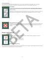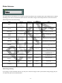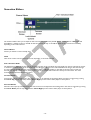
1
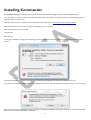
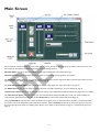
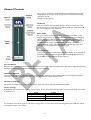
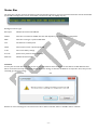
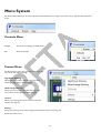
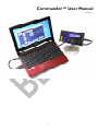
Commander™ User Manual
Version 1.1
-1-
Welcome
Commander is a device control program for the E-Stim Systems Series 2B. This program allows you to directly control your 2B
from a PC via the USB connection.
Although it is written by E-Stim Systems, a lot of the development and ideas have come from its users i.e. you. we have an active
forum where uses can discuss all aspects of Commander, and the 2b, it can be found at
http://www.e-stim.net/commander/
Latest Version
For the latest version of Commander Software you will need to visit. Commander is Free
http://www.e-stim.co.uk/commander/
This software is currently supplied as a BETA version, so there will be possibly problems and odd errors. If you wish to report a bug
then please visit the support forum.
Document Version
Version 1.1
12th July 2011
Copyright Notice
All images and text within this manual are ©E-Stim Systems Ltd 2007-2011
Commander EBox™, EBox 2B™ 2B™ Uplink™ and derivative terms are trademarks of E-Stim Systems Ltd.
All rights reserved. E & OE.
-2-
Index
Welcome ................................................................................................................................................................................................................................... 2
Latest Version...................................................................................................................................................................................................................... 2
Document Version ............................................................................................................................................................................................................. 2
Copyright Notice................................................................................................................................................................................................................ 2
Index ........................................................................................................................................................................................................................................... 3
Quick Start Checklist ............................................................................................................................................................................................................. 4
Installing Commander ............................................................................................................................................................................................................ 5
Main Screen .............................................................................................................................................................................................................................. 6
Channel Controls ............................................................................................................................................................................................................... 7
Off Button....................................................................................................................................................................................................................... 7
Power Slider .................................................................................................................................................................................................................... 7
Increase Button .............................................................................................................................................................................................................. 7
Decrease Button ............................................................................................................................................................................................................ 7
Channel Lock Button .................................................................................................................................................................................................... 7
Channel Level Display................................................................................................................................................................................................... 7
Colour warnings............................................................................................................................................................................................................. 7
Over Level Warning...................................................................................................................................................................................................... 8
Channel Link.................................................................................................................................................................................................................... 8
Channel Shutdown Control ........................................................................................................................................................................................ 8
Power Level Control ......................................................................................................................................................................................................... 8
Power Level change warning....................................................................................................................................................................................... 8
Mode Selector ..................................................................................................................................................................................................................... 9
Mode change warning ................................................................................................................................................................................................... 9
Sensation Sliders ............................................................................................................................................................................................................... 10
Control Name .............................................................................................................................................................................................................. 10
Value................................................................................................................................................................................................................................ 10
Feel / Sensation Slider ................................................................................................................................................................................................. 10
Increase Button ............................................................................................................................................................................................................ 10
Decrease Button .......................................................................................................................................................................................................... 10
Status Bar............................................................................................................................................................................................................................ 11
Timeouts ........................................................................................................................................................................................................................ 11
Commander Control Link.............................................................................................................................................................................................. 12
2B Link Control ................................................................................................................................................................................................................ 13
To Connect ................................................................................................................................................................................................................... 13
Menu System .......................................................................................................................................................................................................................... 14
Controls Menu .................................................................................................................................................................................................................. 14
Presets Menu ..................................................................................................................................................................................................................... 14
High Power Warning .................................................................................................................................................................................................. 14
Mode Change Warning .............................................................................................................................................................................................. 14
Colours........................................................................................................................................................................................................................... 14
Settings............................................................................................................................................................................................................................ 14
Help Menu .......................................................................................................................................................................................................................... 15
About .............................................................................................................................................................................................................................. 15
Debug Log...................................................................................................................................................................................................................... 15
Tool Tips ........................................................................................................................................................................................................................ 15
Colour Options................................................................................................................................................................................................................. 16
Settings ................................................................................................................................................................................................................................ 17
Power Slider Settings .................................................................................................................................................................................................. 17
Feel Control Settings .................................................................................................................................................................................................. 17
Keyboard Controls............................................................................................................................................................................................................... 18
Install USB drivers ................................................................................................................................................................................................................. 19
Identifying the COM Port............................................................................................................................................................................................... 19
Advanced Options ....................................................................................................................................................................................................... 19
-3-
Quick Start Checklist
Before continuing you should read the manual to ensure you are familiar with all the functions of Commander and the interface.
However to refresh your memory we have created a quick checklist.
Install USB divers (Page 19)
Ensure 2B is running the correct firmware.
Commander requires a minimum of Version 2.09
Connect link cable to PC.
Check which COM port it is using. (Page 19)
Install Commander on PC. (Page 5)
Run Commander.
Enable Commander Control Link on 2B (Page 12)
Set Com Port on Link Control & Enable. (Page 13)
See if the 2B responds to Commander
Done!!!!
-4-
Installing Commander
Firstly BEFORE installing Commander ensure you have installed the USB drivers (page 19) and connect the 2B Link cable.
If you already have a previous version of Commander installed you many need to un-install the previous version using the standard
windows software removal tools.
Download latest version of commander from the website. This can be found at http://www.e-stim.co.uk/commander/
Right click and select ‘save as’ (Or ‘save target as’ depending on your browser)
This will download a .zip file to you PC.
Unzip the file.
Run setup.exe
You may get a publisher warning notice. Assuming you have downloaded Commander direct from our website this can safely be
ignored.
Commander will then install and run. The installer will check for prerequisites, and then offer to install them for you.
If you have not connected the USB cable, or if the USB cable drivers have not been installed correctly you may get an error warning
Press quit and connect the USB cable, and then try again. If everything has installed correctly you would be presented with the Main
Screen. You have successfully installed Commander.
-5-
Main Screen
The Commander interface is designed to be simple and easy to use, with all on the main functions visible on the main screen and
less frequently used options are hidden behind the menu and settings systems.
Channel Sliders control the options available on each output channel For more details see page 7.
Channel Link allows you to link both channels together for easier control. See Page 8 for more details.
The Shutdown button allows you to instantly cut the channels to zero with a single click, (Also operated via the ESC key on the
keyboard.) For more details on the shutdown system see page 8.
The Feel and sensation sliders allow you to adjust the feel of the output. For more information see page 10.
The Mode selector gives you the option to change the mode your 2B is operating in. For more details see page 9.
A Power level selector allows you to switch the power setting of your 2B between LOW and HIGH. See page 8 for more details.
The Link Control option gives you control over the communications between the 2B and your PC. You need to enable the
communication link between Commander and the 2B BEFORE any of the other controls will work. (Page 13)
Lastly the Status Bar at the bottom of the Commander Screen gives you up to date information about the communications link,
the and the state of the 2B (battery level and firmware version), and the menu bar (at the top of the screen) gives you access to
the less frequently used options and settings of the 2B. For more details on the status bar see page 11, and the Menu system see
page 14.
-6-
Channel Controls
Two groups of controls are marked Channel A and Channel B control each
output channel on the 2B. The are the PC version of the Channel Intensity
controls on the 2B.
Starting from the bottom.
Off Button
Click the off button will immediately drop the Channel Level to Zero. Can
also be activated from the keyboard by pressing the Z (For Channel A) or X
(For Channel B) keys on the keyboard.
Power Slider
The power sliders are the main up down level control. The Slider can be
dragged with the mouse, or clicked on above and below the slider. Dragging
with the mouse will enable fact level changes, but these changes are only
passed to the 2B when the control is released (Adjust on Drop). Clicking on
the slider above the control will increase the output by a fixed amount
Clicking below the control will reduce the output by the same about. The
exact amount can be adjusted via the Settings Menu
Increase Button
Increases the output by a fixed amount. The exact amount can be adjusted via
the Settings Menu. Can also be triggered by pressing the Q (For channel A)
and the W (For Channel B) Keys on the keyboard.
Decrease Button
Decreases the output by a fixed amount. The exact amount can be adjusted via the Settings Menu. Can also be triggered by pressing
the A (For channel A) and the S (For Channel B) Keys on the keyboard.
Channel Lock Button
Locks the Channel Control. White the channel is locked only the Off button is active. Designed to prevent inadvertent changes
occurring. If the Locked Padlock button is showing then the channel is unlocked and visa versa.
Channel Level Display
The output level. Varies from 0 ‘OFF’ to 100% ‘MAX’. or the users preset limit (See Settings Menu). If the
Colour warnings
By default the power sliders have a colour warning system. As you increase the value the colour of the text will change, from white
to yellow to red.
Level
Colour
OFF to 69%
White
70 to 89%
Yellow
90 to 100%
Red
It is possible to override this system on the menu::settings screen as well as cause some interesting effects if the LCD font colours
are changed to either red or yellow.
-7-
Over Level Warning
It is possible to set a limit to how high the Slider level can be set, and this is defined in the Settings Menu. If it is found to be
impossible to raise the level above a certain point, and the PC beeps then the over level warning is probably in use.
Channel Link
The Channel Link control allows you to like both output Channel A and B together, allowing simpler one
handed control. When the channel Link is in operation Channel A is marked as MASTER and Channel B is
marked as SLAVE.
Adjustments of Channel A will be reflected in Channel B. So to give an example, If Channel A is at 20% and
Channel B at 10%, moving Channel A to 35% will increase Channel B but the same level, i.e. to 25%.
Channel Shutdown Control
The shutdown control, situated between the power sliders will drop both channel outputs immediately. The
shutdown control will override any channel locks and can also be accessed by pressing the Esc key on the
keyboard
Power Level Control
Between the sliders is the power level control buttons. The 2B is capable of operating in two power
settings
LOW
Designed for general usage.
HIGH
Designed for serious players.
Power Level change warning
If you change from Low to High Commander will warn you, than you are about to change to a higher setting. If you find this warning
annoying then you can switch this option off in the Presets Menu.
-8-
Mode Selector
The mode selector control allows you to change the mode of the 2B from a list of available options. Not all 2B modes are available,
depending on the version of Commander and the firmware of the 2B. To change a mode simply select the mode with the mouse.
Mode changes will reset all level settings.
Mode
Diagram
Adjustment
Select+Adjustment
Notes
Pulse
Pulse speed
Pulse Feel
Both channels pulse on and off
Bounce
Pulse speed
Pulse Feel
Channels pulse alternately.
Continuous
Pulse Feel
n/a
Channels are on continuously
A Split
B Split
Pulse speed
Pulse Feel
The Split channel pulse, the other channel is
on continuously
Speed of increase
Wave
The output level increases to the set limit
and then drops to zero before repeating.
Waterfall
Speed of increase
/decrease
Squeeze
Pulse speed
The pulse rate increased and then drops to
slow.
Milk
Pulse speed
The pulse rate increased and then drops to
slow. Channel B is off when Channel A is on
and visa versa.
The output level increases to the set limit
and then decreases to zero before repeating.
Throb
Range of Throb
n/a
Continuous mode with variable feel, rising
from low to adjustment value and then
dropping back to low.
Thrust
Range of Thrust
n/a
Continuous mode with variable feel, rising
from low to adjustment value and then
decreasing back to low.
Random
Amount of
Randomness
Pulse Feel
Random pulsed output.
Step
Step Range
Pulse Feel
Stepped output
Training
Jump Range
Pulse Feel
Output jumps by level.
Mode change warning
If you change a mode Commander will warn you, than you are about to change a mode. If you find this warning annoying then you
can switch this option off in the Presets Menu.
-9-
Sensation Sliders
The sensation sliders allow you to adjust the feel and sensations produced by the 2B. The are the PC version of the Adjust and
Select Button + Adjust Control on the 2B. As with the controls directly on the 2B, the sliders change function and availability
depending on the mode selected.
Control Name
Informs you what the control actually does.
Value
Value of the control. Varies between 2 and 100, depending on the mode selected.
Feel / Sensation Slider
The feel/sensation slider adjusts the value of the control via the mouse. The Slider can be dragged from side to side with the mouse,
or clicked on to the left and right of the central control. Dragging with the mouse will enable fact level changes, but these changes
are only passed to the 2B when the control is released (Adjust on Drop). Clicking on the slider to the left of the control will
decrease the value by a fixed amount, clicking to the right of the control will increase the value by the same about. The exact
amount can be adjusted via the Settings Menu.
Increase Button
Increases the value by a fixed amount. The exact amount can be adjusted via the Settings Menu. Can also be triggered by pressing
the Cursor Up (For the top slider) and the Cursor Right (For the bottom slider) Keys on the keyboard.
Decrease Button
Decreases the output by a fixed amount. The exact amount can be adjusted via the Settings Menu. Can also be triggered by pressing
the Cursor Down (For the top slider) and the Cursor Right (For the bottom slider) Keys on the keyboard.
- 10 -
Status Bar
The status bar is the line of text at the bottom of the Commander interface. It gives current status information of both Commander
and the 2B. The display below is from Commander connected to a 2B, your display may vary.
Reading from left to right
Port Open
Indicates the status of the 2B Link.
COM4
The Link is connected to COM4, this value will depend on your exact machine configuration
9600
The Link is running at a speed of 9600 baud
Low
The 2B is set to LOW power
V2.09
The Firmware version reported by the 2B
7.10V
The current battery voltage
01:71:15
System timer (used for future expansion)
Data Sent
Indicates the data status
Timeouts
You may also see ‘Data Sent’ flash up from time to time, this indicates that Commander has sent data to the 2B. Whenever that
data is received and correctly interpreted, then the Data Sent message is cleared. If the 2B does not respond in time, then you will
eventually get a timeout message.
Reasons for timeout messages are varied but can be due to failure of the link, failure of the 2B or failure of the PC.
- 11 -
Commander Control Link
In order for the Commander software running on your PC to communicate with your 2B you need to enable the link software on
your 2B to listen for commands via the link cable.
You need to be running at least Version 2.09 on the firmware to operate correctly with Commander. For more details on firmware
upgrades visit http://www.e-stim.co.uk/link/
2
c
1.
Switch 2B on.
2.
Select commander mode in a similar way to changing any other mode, by double clicking the select button, and twiddling
the adjust knob to get
2
o
3.
C
A
o
:
4.
C
A
o
:
5.
n
C
t
o
r
m
o
m
l
a
d
e
n
t
d
o
e
r
:
O
B
r
c
h
a
n
f
:
f
O
F
F
g
Now Press Select
m
O
m
F
a
F
n
And twiddle the adjust knob to switch commander mode on
m
O
m
F
a
F
n
d
e
r
:
O
B
n
:
O
F
F
Now press the select button to enable Commander.
The display on the 2B should now show a right pointing arrow, indicating that the Commander Control link is now available.
P
A
u
:
l
O
s
F
e
F
5
~
L
ÿ
O
B
:
:
5
O
0
F
F
If you power off your 2B, the Commander Control Link will still be available when you turn the 2B back on.
To cancel the Commander Control Link follow the procedure above but select Commander:Off or perform a factory reset.
- 12 -
Connect cable to 2B and PC
run Commander on PC
2B Link Control
The link control tells commander which COM port to use to communicate with the link cable, as well as giving you control over the
actual connection. Before running Commander you must ensure the link cable is connected, otherwise the COM port may not be
recognised by Commander
The link Control has 3 elements, a drop down box to select the COM port, and two connect disconnect buttons. If a button is grey
out, then it is generally not available.
In the picture above the connect button is grey out as the PC is connected to the COM port (in this case COM4).
To Connect
Firstly ensure that the cable is connected to your PC and the 2B, the drivers have been correctly installed, and the 2B has the
Commander Control Link enabled (right pointing arrow on bottom link of 2B screen)
1.
select the Com Port
2.
Press the Connect Button
The status line on the bottom of the commander interface screen should now change to show
This indicated the Port is Open, on COM4 and is running at a speed of 9600. You might see a different COM port depending on the
configuration of your PC
Sending Test Commands
- 13 -
Menu System
The Menu systems allows you to control aspects of Commander that you might not need on a day to day basis, but still need to
access.
Controls Menu
Defaults
Sets all control settings to default levels.
Exit
Exits Commander.
Presets Menu
The Presets menu offers you control over warnings, and
some of the less obvious settings.
High Power Warning
Allows you to turn off the automatic warning about
switching to high power. Click to toggle
Mode Change Warning
Allows you to turn off the automatic warning which
occurs when you change mode. Click to toggle
Colours
Allows you to change the colours of the Commander
Interface (see page 15)
Settings
Allows you to change some of the settings of Commander Interface ( See Page 16)
Presets are saved on exit.
- 14 -
Help Menu
The help System
About
Pops up a screen giving version information about Commander
Debug Log
Tool Tips
If tool tips are enabled then when you hover the mouse over a control you should see a bubble pop up with a little information
about the control. This is a useful system for beginners, but for the advanced user it can become annoying, so it is possibly to switch
it off.
- 15 -
Colour Options
It is possible to change the colours on the Commander interface, to suit your personal tastes.
Background
The Colour of the background of Commander
Foreground
The colour of the main text
LCD Background
The Colour of the background of the value displays on Commander (default colour is blue). Be careful if
you select white, red or yellow as a background as this will cause issues when the colour warning system
is being used. (Yellow on Yellow just doesn’t work well!!
LCD Text
The Colour of the text in the value displays on Commander. If colour warnings are switched on, these
will override the colours set here.
Default Colours
Resets all the colours to system defaults
Background ; Dark Green
Foreground : Yellow
LCD Background : Dark Blue
LCD Foreground : White
Colour changes are saved by Commander, so when you re-run Commander your colours will be as you have set them.
- 16 -
Settings
Power Slider Settings
Max Level
The maximum level it is possible to set the power slider to.
Slider Step
The amount the slider will increase or decrease when the power slider is clicked.
Button Step
The amount the value will increase or decrease when the slider button, or the relevant keyboard key is
pressed.
Colour Warning
Enable or disable the colour warning system
Feel Control Settings
Slider Step
The amount the slider will increase or decrease when the feel slider is clicked.
Button Step
The amount the value will increase or decrease when the slider button, or the relevant keyboard key is
pressed.
The cancel button allows you the exit the setting screen, without saving any changes.
The Close button exits the settings screen and saves the settings. The saved settings persist even
when Commander is shutdown.
- 17 -
Keyboard Controls
As well as the mouse, it is possible to use the keyboard to control the 2B via Commander.
The feel sliders also have similar controls around the cursor keys
- 18 -
Install USB drivers
The USB driver allows your PC to talk to the electronics within the USB cable itself. Once the divers are installed you should not
have to re-install them again.
Install USB drivers. These can be loaded from the CD or downloaded from http://www.e-stim.co.uk/link/index.php#drivers
The drivers are available in both executable or zipped ‘.zip’ formats. Modern windows computers can cope with both variations.
Simply right click on the file link, select ‘save Target as’ to save to a suitable place on your computer and then double click on the
executable (.exe) file. The USB drivers should then install.
Now connect the PC Link cable to a spare USB port. You should see Windows recognise it and attempt to activate the drivers.
Identifying the COM Port
Now you need to see what COM port your computer has allocated to the cable. To do this you need to look at the device
manager. Click on the windows start button, and then right click on ‘Computer’ and then select ‘Manage’. This should open the
Computer manager.
In the left hand column select device manager. In the right hand column look for PORTS (COM & LPT) under this you should see
‘USB Serial Port (Com x)’ Where x is a number. Note this down.
Advanced Options
You do not need to set any of the advanced options on the COM port (baud rate stop bits etc, as these are all controlled directly
by the uplink program.
- 19 -