1
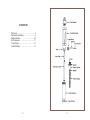
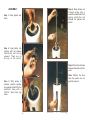
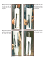
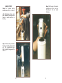
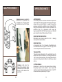
PERFORATOR
USER GUIDE
Holte Manufacturing Company, Inc.
25310 Jeans Road, Veneta OR 97487
Ph (541)935-5054 Fax (541)935-5430
www.drilling.com
CONTENTS
Parts List... .............................................3
Perforator Assembly.. ............................4
Adapter Shoes... ..................................10
Air Pressures........................................11
Travel Stops..........................................11
Cutter Wheels.......................................11
2
3
Step 4. Slide chrome rod
through spring with a
washer on each side of the
spring. Install the rod
through the cylinder and
piston.
ASSEMBLY
Step 1. Place gasket over
holes.
Step 2. Insert piston into
cylinder with the shallow
chamfered end facing
outward. There are no
O-rings on the piston.
Step 5. Place the stop tube
between the piston and the
yoke.
Note: Without the stop
tube, the piston can not
push the yoke out.
Step 3. With piston in
cylinder, position cylinder
over gasket and bolt it to the
perforator body with a
2-3/8”x1” allen head cap
screw.
4
5
Step 6. Screw the chrome rod
into the yoke with the
chamfered side of the yoke
facing down.
Step 8. Slide cutter wheel
and axle pin up into yoke.
Insert axle pin bolt through
yoke and tighten.
Step 7. Place cutter wheel into
perforator body and slide axle
pin through cutter wheel.
Step 9. Photo of perforator
body assembly complete.
6
7
QUICK TEST
Step 12. The pop off valve is
installed as one unit by
threading it into the lower
housing.
Step 10. Tighten spring
loaded rod with a ¾” wrench.
After tightening chrome rod,
push assembly through entire
stroke to insure there is no
binding.
Step 11. Place the protective
housing over the cylinder and
rod. This is tightened handtight or slightly snugged with a
wrench.
8
9
ADAPTER SHOES
OPERATING HINTS
Adapter shoes are available to
allow the 6” perforator to
perforate up to 12” pipe. Larger
perforators cut up to 26” pipe.
AIR PRESSURE
Air or water pressure of at least 60-70 PSI is required to
set the wheel into cutting position. When the perforator is
under water, you must add air or water to equal the
pressure outside the perforator plus at least 40 PSI.
Using more pressure does not cause a problem. The
perforator pop off or developing valve opens at
approximately 80 to 90 PSI. Down pressure on the drill
pipe makes the wheel rotate and punch holes.
PERFORATOR ORIENTATION
Perforations are made when the tool is moving
downward from top to bottom.
PERFORATIONS
As a general rule, 3 to 4 columns of perforations is
recommended for 6” to 8” pipe. For 10” to 12” pipe, 6 to 8
columns of perforations are recommended.
TRAVEL STOPS
Travel stops are attached to the perforator body to
restrict the reach of the wheel. For casing thinner than
.250” remove the travel stops. This allows the wheel to
extend out of the perforator further for the thinner walled
casing.
Adapters slide onto the
back of the perforator body
and bolt to the holes which
line up on the sides of the
perforator.
10
CUTTER WHEELS
Remember to retract the cutter wheel before rotating.
Frequently inspect cutter wheel for wear. Inspect for
excessive wear between blade and axle pin. Use PVC
cutter wheels when perforating PVC pipe.
11