1
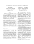
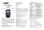
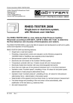
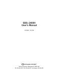
MARTIN® Insertable
Dust Collector
Go to MARTIN® Insertable Dust Collector web page
Operator’s Manual
M3416
Important
MARTIN ENGINEERING HEREBY DISCLAIMS ANY LIABILITY FOR: DAMAGE DUE TO
CONTAMINATION OF THE MATERIAL; USER’S FAILURE TO INSPECT, MAINTAIN AND TAKE
REASONABLE CARE OF THE EQUIPMENT; INJURIES OR DAMAGE RESULTING FROM USE OR
APPLICATION OF THIS PRODUCT CONTRARY TO INSTRUCTIONS AND SPECIFICATIONS
CONTAINED HEREIN. MARTIN ENGINEERING’S LIABILITY SHALL BE LIMITED TO REPAIR
OR REPLACEMENT OF EQUIPMENT SHOWN TO BE DEFECTIVE.
Observe all safety rules given herein along with owner and Government standards and regulations. Know
and understand lockout/tagout procedures as defined by American National Standards Institute (ANSI)
z244.1-1982, American National Standard for Personnel Protection - Lockout/Tagout of Energy Sources Minimum Safety Requirements and Occupational Safety and Health Administration (OSHA) Federal
Register, Part IV, 29 CFR Part 1910, Control of Hazardous Energy Source (Lockout/Tagout); Final Rule.
The following symbols may be used in this manual:
!
DANGER
Danger: Immediate hazards that will result in severe personal injury or death.
!
WARNING
Warning: Hazards or unsafe practices that could result in personal injury.
!
CAUTION
Caution: Hazards or unsafe practices that could result in product or property damages.
IMPORTANT
Important: Instructions that must be followed to ensure proper installation/operation of equipment.
NOTE
Note: General statements to assist the reader.
Section
Page
List of Figures . . . . . . . . . . . . . . . . . . . . . . . . . . . . . . . . . . . . . . . . . . . . . . . . . . . . . . . . . . . . ii
Introduction . . . . . . . . . . . . . . . . . . . . . . . . . . . . . . . . . . . . . . . . . . . . . . . . . . . . . . . . . . . . . . 1
General . . . . . . . . . . . . . . . . . . . . . . . . . . . . . . . . . . . . . . . . . . . . . . . . . . . . . . . . . . . . . . . . . . . . . .
Location requirements for transfer point installations . . . . . . . . . . . . . . . . . . . . . . . . . . . . . . . . . .
References . . . . . . . . . . . . . . . . . . . . . . . . . . . . . . . . . . . . . . . . . . . . . . . . . . . . . . . . . . . . . . . . . . .
Safety . . . . . . . . . . . . . . . . . . . . . . . . . . . . . . . . . . . . . . . . . . . . . . . . . . . . . . . . . . . . . . . . . . . . . . .
Materials required . . . . . . . . . . . . . . . . . . . . . . . . . . . . . . . . . . . . . . . . . . . . . . . . . . . . . . . . . . . . .
Before Installing Dust Collector . . . . . . . . . . . . . . . . . . . . . . . . . . . . . . . . . . . . . . . . . . . . . .
Installing Dust Collector . . . . . . . . . . . . . . . . . . . . . . . . . . . . . . . . . . . . . . . . . . . . . . . . . . . .
1
1
1
2
2
3
4
Electrical connections . . . . . . . . . . . . . . . . . . . . . . . . . . . . . . . . . . . . . . . . . . . . . . . . . . . . . . . . . . 8
Installing timer enclosure. . . . . . . . . . . . . . . . . . . . . . . . . . . . . . . . . . . . . . . . . . . . . . . . . . . . . . . . 9
Initial Operation of Dust Collector . . . . . . . . . . . . . . . . . . . . . . . . . . . . . . . . . . . . . . . . . . . . 11
Maintenance. . . . . . . . . . . . . . . . . . . . . . . . . . . . . . . . . . . . . . . . . . . . . . . . . . . . . . . . . . . . . . 12
Part Numbers . . . . . . . . . . . . . . . . . . . . . . . . . . . . . . . . . . . . . . . . . . . . . . . . . . . . . . . . . . . . . 13
Martin Engineering M3416-10/11
i
MARTIN® Insertable Dust Collector
Table of Contents
Table of Contents
List of Figures & Tables
List of Figures
Figure
1
2
3
4
5
6
7
8
Title
Page
®
Dimensions for MARTIN Insertable Dust Collector,
P/N INS-08XX and INS-10XX . . . . . . . . . . . . . . . . . . . . . . . . . . . . . . . . . . . . . . 4
Dimensions for MARTIN® Insertable Dust Collector, P/N INS-15XX. . . . . . . . 5
Dimensions for MARTIN® Insertable Dust Collector,
P/N INS-18XX and INS-20XX . . . . . . . . . . . . . . . . . . . . . . . . . . . . . . . . . . . . . . 6
Dimensions for MARTIN® Insertable Dust Collector, P/N INS-30XX. . . . . . . . 7
Electrical and Plumbing Detail . . . . . . . . . . . . . . . . . . . . . . . . . . . . . . . . . . . . . . . 8
Solenoid Enclosure . . . . . . . . . . . . . . . . . . . . . . . . . . . . . . . . . . . . . . . . . . . . . . . . 9
Solenoid Wiring Schematic . . . . . . . . . . . . . . . . . . . . . . . . . . . . . . . . . . . . . . . . . 9
Timer Enclosure Electrical Connections. . . . . . . . . . . . . . . . . . . . . . . . . . . . . . . . 10
List of Tables
Table
I
II
III
IV
V
Title
Page
Preventative Maintenance Schedule . . . . . . . . . . . . . . . . . . . . . . . . . . . . . . . . . . . 12
MARTIN® Insertable Dust Collector Part Numbers . . . . . . . . . . . . . . . . . . . . . . 13
MARTIN® Insertable Dust Collector Part Numbers . . . . . . . . . . . . . . . . . . . . . . 13
CPV PowerCore® DC Manual Kit Part Numbers . . . . . . . . . . . . . . . . . . . . . . . . 14
MARTIN® Insertable Dust Collector Part Numbers and Weights . . . . . . . . . . . . 14
Martin Engineering M3416-10/11
ii
MARTIN® Insertable Dust Collector
General
The MARTIN® Insertable Dust Collector is an automatic, reverse air dust
filter designed to remove dust from the air in conveyor transfer points, silo
vents, bucket elevators, and screens. The unit is made up of a group of filter
elements mounted on a sealed frame. The elements are fitted side-by-side in
an individual sealing arrangement that effectively separates the dirty (inlet)
side of the filter from the clean (outlet) side. The elements are always
removed for maintenance from the clean side of the filter.
This manual provides instructions for locating and installing the MARTIN®
Insertable Dust Collector at a conveyor transfer point or silo. For instructions
on installing units on bucket elevators or screens, call Martin Engineering or a
representative. Information on unit components, assembly, electrical
requirements, operation, maintenance, and troubleshooting can be found in
the user manual supplied with your unit.
Location
requirements for
transfer point
installations
To ensure the dust collector’s maximum effectiveness, make sure the transfer
point is properly sealed and designed with dust control in mind, as follows:
• Chute length: For standard materials or belt speeds up to 250 fpm
(1.3 m/s), the transfer point chute length should equal 2 ft per 100 fpm
(210 mm per 0.5 m/s) of belt speed. For very dusty materials or belt speeds
of 300 fpm (1.5 m/s) and higher, the chute length should equal 3 ft per
100 fpm (914 mm per 0.5 m/s) of belt speed. When in doubt, make the chute
longer.
• Chute height: For standard materials or belt speeds up to 250 fpm
(1.3 m/s), the chute wall should be at least 12 in. (305 mm) high. For very
dusty materials or belt speeds of 300 fpm (1.5 m/s) and higher, it should be
at least 24 in. (610 mm) high.
• Distance from load zone: Locate dust collector as far from actual load
zone as possible, and 1/3 of the chute length back from the chute exit point.
For best results, install a dust curtain at the exit of the chute. For information
on transfer point wear liners and sealing systems, call Martin Engineering or a
representative.
References
The following documents are referenced in this manual:
• American National Standards Institute (ANSI) z244.1-1982, American
National Standard for Personnel Protection - Lockout/Tagout of Energy
Sources - Minimum Safety Requirements, American National Standards
Institute, Inc., 1430 Broadway, New York, NY 10018.
• Federal Register, Volume 54, Number 169, Part IV, 29 CFR Part 1910,
Control of Hazardous Energy Source (Lockout/Tagout); Final Rule,
Department of Labor, Occupational Safety and Health Administration
(OSHA), 32nd Floor, Room 3244, 230 South Dearborn Street, Chicago, IL
60604.
• Donaldson® Torit® Preventative Maintenance Schedule for DF, DFT, DFO,
TD, HP, PJ, DLMC, Unicell, Maxcell Dust Collectors, Donaldson
Company, Inc., June 2003.
Torit® PowerCore® is a registered trademark of Donaldson Company, Inc.
Martin Engineering M3416-10/11
1
MARTIN® Insertable Dust Collector
Introduction
Introduction
Introduction
Safety
All safety rules defined in the above documents and all owner/employer safety
rules must be strictly followed when working on this equipment.
Materials required
In addition to standard hand tools, a hoist is required to install this equipment.
Martin Engineering M3416-10/11
2
MARTIN® Insertable Dust Collector
IMPORTANT
The delivery service is responsible for damage occurring in
transit. Martin Engineering CANNOT enter claims for
damages. Contact your transportation agent for more
information.
1. Inspect shipping container for damage. Report damage to delivery service
immediately and fill out delivery service’s claim form. Keep any damaged
goods subject to examination.
2. Remove dust collector from shipping container. Equipment in container
should include dust collector and controller.
3. If anything is missing, contact Martin Engineering or representative.
!
WARNING
Before installing equipment, turn off and lock out/tag out
energy source to conveyor and conveyor accessories.
4. Turn off and lock out/tag out energy source according to ANSI standards
(see “References”).
!
WARNING
If equipment will be installed in an enclosed area, gas level or
dust content must be tested before using a cutting torch or
welding. Using a cutting torch or welding in an area with gas
or dust may cause an explosion.
5. If using a cutting torch or welding, test atmosphere for gas level or dust
content. Cover conveyor belt with fire retardant cover.
Martin Engineering M3416-10/11
3
MARTIN® Insertable Dust Collector
Before Installation
Before Installing Dust Collector
Installation
Installing Dust Collector
1. Make sure conveyor belt structure and chutework will support dust
collector. See Table V for weight specifications.
2. Determine how to best install dust collector on your application. See
Figures 1–4 for dimensions.
3. Follow instructions in the included installation manual to install dust
collector.
Figure 1. Dimensions for MARTIN® Insertable Dust Collector,
P/N INS-08XX and INS-10XX
Martin Engineering M3416-10/11
4
MARTIN® Insertable Dust Collector
Installation
Figure 2. Dimensions for MARTIN® Insertable Dust Collector, P/N INS-15XX
Martin Engineering M3416-10/11
5
MARTIN® Insertable Dust Collector
Installation
Figure 3. Dimensions for MARTIN® Insertable Dust Collector,
P/N INS-18XX and INS-20XX
Martin Engineering M3416-10/11
6
MARTIN® Insertable Dust Collector
Installation
Figure 4. Dimensions for MARTIN® Insertable Dust Collector, P/N INS-30XX
Martin Engineering M3416-10/11
7
MARTIN® Insertable Dust Collector
Installation
Electrical Power Supply*
Timer Enclosure
Motor Power
Supply Wires*
Motor Starter*
Timer 120V Power Supply Wires*
Control Wires*
Filter-Regulator Unit
Compressed
Air Supply*
(80-100 PSI)
Air
Supply Line*
Lockout Valve
*Indicates components are supplied by customer
Figure 5. Electrical and Plumbing Detail
Electrical
connections
!
WARNING
All electrical work must be done to National Electrical Code (NEC)
standards. See “References.”
!
DANGER
For explosion-proof dust collector units, properly ground unit to earth
by connecting a ground wire to the earthing boss on the unit. Failure
to properly ground the unit can result in a static electricity explosion,
damage to equipment, and severe injury or death.
1. For explosion-proof units with INS-XE part numbers, properly connect a ground
wire to the unit’s earthing boss (located on the unit next to the symbol shown
below) to prevent static electricity buildup. Use the brass screw provided to
connect the ground wire to the unit.
!
WARNING
Before making any connections, lock out/tag out electrical supply to
control system according to ANSI standards (see “References”).
2. Connect blower motor to power supply:
a. Determine power requirements for motor (see Table III).
b. Install a motor starter (not included) per local requirements and codes.
c. Interlock motor and timer enclosure and control per plant PLC.
Martin Engineering M3416-10/11
8
MARTIN® Insertable Dust Collector
Installing timer
enclosure
CAUTION
Do not mount enclosure in area subject to shock, vibration,
temperatures exceeding 130°F (55°C), or explosion. Damage
to control system circuitry could result.
1. Determine location for timer enclosure.
2. Mount onto wall with fasteners.
3. Drill conduit holes in enclosure for solenoid and power wires. Use care
not to damage internal components. Drill in most weather-proof location
available on enclosure.
B
A
C
A. Screws
B. Solenoid Enclosure Cover
D
C D
C. Solenoid Terminal (Line)
D. Solenoid Terminal (Neutral)
Figure 6. Solenoid Enclosure
4. Loosen screws (A) and remove solenoid enclosure cover (B).
Solenoid Enclosure
SOL
1
Factory Wired
Wired at Installation
SOL
2
SOL
3
SOL
4
SOL
5
SOL
6
COM
L1
L2 COM
1 2 3 4 5 6
Timer Enclosure Terminal Block
Figure 7. Solenoid Wiring Schematic
Martin Engineering M3416-10/11
9
MARTIN® Insertable Dust Collector
Installation
!
Installation
5. Using electrical connectors, route required wires from solenoid valves to
timer enclosure. Connect wires to solenoid terminals.
6. Reinstall solenoid enclosure cover (B, Figure 6).
L1
Solenoids
L2 Com
Figure 8. Timer Enclosure Electrical Connections
7. Route power wire (120VAC 60Hz) into timer enclosure.
8. Connect ground wire to ground terminal. Connect neutral wire to terminal
labeled L2. Connect phase wire to terminal labeled L1.
9. Reinstall timer enclosure cover.
Martin Engineering M3416-10/11
10
MARTIN® Insertable Dust Collector
IMPORTANT
Read entire section before beginning work.
!
WARNING
Dust collector may produce loud noise when mounted on
structure. See OSHA 1910.95 for guidelines. If required,
wear ear protection to avoid impairment or loss of hearing.
1. If dust collector produces loud noise according to OSHA 1910.95, wear
ear protection.
!
WARNING
Failure to remove tools from installation area and conveyor
belt before turning on energy source can cause serious injury
to personnel and damage to belt.
2. Remove all tools and fire retardant cover from installation area and
conveyor belt.
!
DANGER
Do not touch or go near conveyor belt or conveyor accessories
when conveyor belt is running. Body or clothing can get
caught and pull body into conveyor belt, causing severe injury
or death.
3. Turn power ON at the source.
4. Start blower fan for one second, then stop.
5. Check motor and fan for the correct rotation by referencing the rotation
sticker located on the motor mounting plate. Check for smooth operations
of fan wheel and motor. If motor is not rotating in correct direction, lock
out/tag out energy source and reverse rotation.
6. Ensure damper is set in completely closed position.
7. Turn compressed air on at the source. Adjust the regulator until pressure
is between 90 and 100 PSI (6.2–6.8 Bar).
8. Turn conveyor belt ON and ensure material is flowing.
9. Turn the blower fan ON.
10. Open the damper 50% while the dust collector is under dust load.
11. Operate dust collector for 5 to 10 minutes.
12. Open the damper until the transfer point is under a negative air flow.
13. Operate and maintain dust collector according to user manual supplied
with your unit.
Martin Engineering M3416-10/11
11
MARTIN® Insertable Dust Collector
Operation
Initial Operation of Dust Collector
Maintenance
Maintenance
Table I. Preventative Maintenance Schedule
Item
Monitor Exhaust of Fan
to ensure filter integrity.
Collector Filter
Pressure Drop
Filter Pressure Drop
Pneumatic Lines
Compressed
Air Supply
Frequency
Procedure
Daily
Monitor exhaust from fan. The exhaust should remain visibly clean. If a leak of dust
develops, it will be noticed as a visual puff from the fan exhaust immediately after a
cleaning pulse. If dust is visible consult your Installation and Operation Manual for
troubleshooting recommendations.
Weekly
Visually inspect and record the operating pressure drop across each dust collector. It is
normal for the pressure drop to fluctuate during operation as the collector passes
through cleaning cycles, and as production schedules fluctuate from light to heavy.
New filters may have a pressure drop of less than 1” w.g., however, as filters become
seasoned, they will reach an equilibrium pressure drop. Generally 1 to 6” w.g. is
considered normal. An excessively high pressure drop could be an indication of a
malfunction in the cleaning mechanism, excessive airflow, plugged filters, or heavy
dust loading conditions. Consult your Installation and Operation Manual for
troubleshooting recommendations.
Monthly
To ensure correct pressure drop indication, remove one line at a time from the
pressure drop indicating gauge barb fitting. Using a minimum 20 psi compressed air,
blow through the line back towards the dust collector. (Do not use more than 25 psi to
blow through clear poly tubing as damage may occur.)
Monthly
Air dryers and automatic condense valve should be used prior to each dust collector.
Inspect monthly to ensure proper operation, and that moisture is being removed from
the compressed air supply. Troubleshoot, repair, or replace per the specific
manufactures’ instructions. Consult your Installation and Operation Manual for correct
pulse pressure recommendations for the dust collector.
Pulse Diaphragms
Apply electrical and pneumatic service to the pulse cleaning control. Activate the pulse
cleaning sequence by placing the control in continuous cleaning mode. Approximately
Every 3 Months
every ten (10) seconds an audible pulse should be heard. This process should be
performed simultaneously with the solenoid check described below.
Electrical Solenoids
Apply electrical and pneumatic service to the pulse cleaning control. Activate the pulse
cleaning sequence by placing the control in continuous cleaning mode. Approximately
every ten (10) seconds an audible pulse should be heard. Additionally, each solenoid
Every 3 Months should be inspected manually by placing a large flat, light-weight surface (cloth) behind
each solenoid enclosure. As each solenoid is activated, in that particular enclosure,
visually inspect the test surface for movement. (When the solenoid is energized,
compressed air is released from the diaphragm valves through the solenoid.)
Verify conditions
of Filters
If filter element pressure drop exceeds 6” w.g. verify proper system airflow according to
original design recommendations. Remember that excessive airflow can increase
Every 6 Months
pressures drop. Change filters if necessary. Always use Donaldson superior filters for
best performance and life.
Verify operations of
Pulse Cleaning
System
Inspect Diaphragms, Solenoids and Timer to ensure proper filter cleaning. Consult the
Every 6 Months Installation and Operation Manual for your dust collector for the correct On and Off time
settings for Pulse cleaning intervals and duration.
Check fan and motor
Check motor and fan for the correct rotation by referencing the rotation sticker located
on the motor mounting plate. Check for smooth operations of fan wheel and motor.
Every 6 Months
Inspect for and tighten belts, nuts, bolts and set screws as needed. Consult the
Installation and Operation Manual for troubleshooting recommendations as needed.
Adjust exhaust Damper
Every 6 Months
as needed
Install filters correctly
Adjust exhaust Damper
Airflow should be adjusted to match design recommendations. Excessive airflow can
shorten filter life and cause fan motor failure.
During filter
changes
Consult the Installation and Operation Manual for recommendations to correctly install
new filters. Install new filters correctly and adequately tightened to prevent dust
leakage. Improperly installed or inadequately tightened filters can allow dust to pass
through the dust collector.
Immediately
after filter
changes
Because the pressure drop or restriction to airflow through the filters will decrease
when new filters are installed, airflow through the collector will increase. Because of
this it is necessary to adjust the fan damper to restrict the airflow through the collector
to the recommended level immediately after installation of new filters. As the filters age
and the pressure drop or restrictions to air increases, you may need to open the
damper to reach design conditions.
Martin Engineering M3416-10/11
12
MARTIN® Insertable Dust Collector
See the following tables for MARTIN® Insertable Dust Collector unit assembly part numbers. For replacement filter
elements, manifold valves, and solenoid valves, call Martin Engineering at 800-544-2947.
Table II. MARTIN® Insertable Dust Collector Part Numbers
Item
Description
PowerCore®
1
CPV
2
TRB Fan Pack
PowerCore®
Dust Collector
Part Number
Quantity
Table III
1
Table III
1
38435-K (See Table IV)
1
3
CPV
4
Adapter Flange Weldment
Table III
1
5
Hardware Kit
Table III
1
DC Manual Kit
Table III. MARTIN® Insertable Dust Collector Part Numbers
Part No.
Airflow
CFM
Voltage
P/N
Item 1
P/N
Item 2
P/N
Item 4
P/N
Item 5
INS-084
0-800
460V 60Hz
38432-2
38433-2
38627-CPV-2
38627-2H
INS-084E
0-800
460V 60Hz
38432-2E
38433-2E
38627-CPV-2
38627-2H
INS-084EH
0-800
460V 60Hz
38432-2EH
38433-2E
38627-CPV-2
38627-2H
INS-103
0-1000
380V 50Hz
38432-2
38434-3-38050
38627-CPV-2
38627-2H
INS-104
800-1000
460V 60Hz
38432-2
38433-3
38627-CPV-2
38627-2H
INS-104E
800-1000
460V 60Hz
38432-2E
38433-3E
38627-CPV-2
38627-2H
INS-104EH
800-1000
460V 60Hz
38432-2EH
38433-3E
38627-CPV-2
38627-2H
INS-153
1000-1500
380V 50Hz
38432-3
38434-3-38050
38627-CPV-3
38627-3H
INS-154
1000-1500
460V 60Hz
38432-3
38433-3
38627-CPV-3
38627-3H
INS-154E
1000-1500
460V 60Hz
38432-3E
38433-3E
38627-CPV-3
38627-3H
INS-154EH
1000-1500
460V 60Hz
38432-3EH
38433-3E
38627-CPV-3
38627-3H
INS-184
1500-1800
460V 60Hz
38432-4
38434-3
38627-CPV-4
38627-4H
INS-184E
1500-1800
460V 60Hz
38432-4E
38434-3E
38627-CPV-4
38627-4H
INS-184EH
1500-1800
460V 60Hz
38432-4EH
38434-3E
38627-CPV-4
38627-4H
INS-203
1500-2000
380V 50Hz
38432-4
38434-5-38050
38627-CPV-4
38627-4H
INS-204
1800-2000
460V 60Hz
38432-4
38433-5
38627-CPV-4
38627-4H
INS-204E
1800-2000
460V 60Hz
38432-4E
38433-5E
38627-CPV-4
38627-4H
INS-204EH
1800-2000
460V 60Hz
38432-4EH
38433-5E
38627-CPV-4
38627-4H
INS-303
2000-3000
380V 50Hz
38432-6
38434-7.5-38050
38627-CPV-6
38627-6H
INS-304
2000-3000
460V 60Hz
38432-6
38434-5
38627-CPV-6
38627-6H
INS-304E
2000-3000
460V 60Hz
38432-6E
38434-5E
38627-CPV-6
38627-6H
INS-304EH
2000-3000
460V 60Hz
38432-6EH
38434-5E
38627-CPV-6
38627-6H
Martin Engineering M3416-10/11
13
MARTIN® Insertable Dust Collector
Part Numbers
Part Numbers
Part Numbers
Table IV. CPV Powercore® DC Manual Kit Part Numbers
Item
Description
Part Number
Quantity
1
Nipple Hex 1-NPT
36009
5
2
Union 1-NPT Galvanized
36274
2
3
Valve Ball Safety Shutoff 1 NPT
32284-04
2
4
Gauge Air GLYSRL Fill 1/4-NPT 160 PSI
34842
1
5
Filter/Regulator 1-NPT
38736
1
6
Operator’s Manual
M3416
1
Table V. MARTIN® Insertable Dust Collector Part Numbers and Weights
MARTIN® Insertable Dust Collector*
Part No.
DCE
Model No.
Weight
lb (kg)
Adapter Flange
P/N
38432-2
CPV-2
320 (145)
38627-CPV-2
38432-3
CPV-3
400 (181)
38627-CPV-3
38432-4
CPV-4
500 (227)
38627-CPV-4
38432-6
CPV-6
655 (297)
38627-CPV-6
Dust Collector Motor*
Part No.
Power
hp
Weight
lb (kg)
38433-2
2
63 (29)
38433-3
3
87 (39)
38433-5
5
124 (56)
38434-3
3
155 (70)
38434-5
5
178 (81)
* For explosive environments, add an E to end of dust collector and motor part numbers.
Martin Engineering M3416-10/11
14
MARTIN® Insertable Dust Collector
Any product, process, or technology described here may be the subject of intellectual property rights reserved by
Martin Engineering Company. Trademarks or service marks designated with the ® symbol are registered with the U.S.
Patent and Trademark Office and may be proprietary in one or more countries or regions. Other trademarks and
service marks belonging to Martin Engineering Company in the United States and/or other countries or regions may
be designated with the “TM” and “SM” symbols. Brands, trademarks, and names of other parties, who may or may
not be affiliated with, connected to, or endorsed by Martin Engineering Company, are identified wherever possible.
Additional information regarding Martin Engineering Company’s intellectual property can be obtained at
www.martin-eng.com/trademarks.
Martin Engineering USA
One Martin Place
Neponset, IL 61345-9766 USA
800 544 2947 or 309 852 2384
Fax 800 814 1553
www.martin-eng.com
Form No. M3416-10/11
Subject to change without prior notice.
Quality Management System Certified by DNV - ISO 9001
© Martin Engineering Company 1998, 2011