1
1
DGS-1510 Series Gigabit Ethernet SmartPro Switch CLI Reference Guide
Table of Contents
1.
Introduction ...................................................................................................................................................................... 1
2.
Basic CLI Commands ................................................................................................................................................... 10
3.
802.1X Commands........................................................................................................................................................ 24
4.
Access Control List (ACL) Commands.......................................................................................................................... 38
5.
Access Management Commands ................................................................................................................................. 68
6.
ARP Spoofing Prevention Commands .......................................................................................................................... 85
7.
Asymmetric VLAN Commands ...................................................................................................................................... 87
8.
Authentication, Authorization, and Accounting (AAA) Commands ............................................................................... 88
9.
Basic IPv4 Commands ................................................................................................................................................ 113
10.
Basic IPv6 Commands ............................................................................................................................................. 120
11.
Cable Diagnostics Commands ................................................................................................................................. 129
12.
Command Logging Commands ............................................................................................................................... 132
13.
Debug Commands ................................................................................................................................................... 133
14.
DHCP Auto-Configuration Commands..................................................................................................................... 145
15.
DHCP Client Commands.......................................................................................................................................... 147
16.
DHCP Relay Commands.......................................................................................................................................... 151
17.
DHCP Snooping Commands ................................................................................................................................... 172
18.
DHCPv6 Client Commands ...................................................................................................................................... 191
19.
DHCPv6 Guard Commands ..................................................................................................................................... 194
20.
DHCPv6 Relay Commands ...................................................................................................................................... 198
21.
Digital Diagnostics Monitoring (DDM) Commands ................................................................................................... 204
22.
D-Link Discovery Protocol (DDP) Client Commands ............................................................................................... 213
23.
Domain Name System (DNS) Commands ............................................................................................................... 216
24.
DoS Prevention Commands ..................................................................................................................................... 223
25.
Dynamic ARP Inspection Commands ...................................................................................................................... 227
26.
Error Recovery Commands ...................................................................................................................................... 241
27.
File System Commands ........................................................................................................................................... 245
28.
Filter Database (FDB) Commands ........................................................................................................................... 251
29.
GARP VLAN Registration Protocol (GVRP) Commands ......................................................................................... 264
30.
Gratuitous ARP Commands ..................................................................................................................................... 272
31.
IGMP Snooping Commands .................................................................................................................................... 275
32.
Interface Commands ................................................................................................................................................ 291
33.
IP Source Guard Commands ................................................................................................................................... 305
34.
IP Utility Commands ................................................................................................................................................. 311
35.
IP-MAC-Port Binding (IMPB) Commands ................................................................................................................ 313
36.
IPv6 Snooping Commands....................................................................................................................................... 317
37.
IPv6 Source Guard Commands ............................................................................................................................... 322
38.
Japanese Web-based Access Control (JWAC) Commands .................................................................................... 328
ii
DGS-1510 Series Gigabit Ethernet SmartPro Switch CLI Reference Guide
39.
Jumbo Frame Commands ........................................................................................................................................ 340
40.
Link Aggregation Control Protocol (LACP) Commands ........................................................................................... 341
41.
Link Layer Discovery Protocol (LLDP) Commands .................................................................................................. 348
42.
Loopback Detection (LBD) Commands.................................................................................................................... 378
43.
MAC Authentication Commands .............................................................................................................................. 384
44.
Mirror Commands ..................................................................................................................................................... 388
45.
MLD Snooping Commands ...................................................................................................................................... 392
46.
Multiple Spanning Tree Protocol (MSTP) Commands ............................................................................................. 409
47.
Neighbor Discovery (ND) Inspection Commands .................................................................................................... 418
48.
Network Access Authentication Commands ............................................................................................................ 422
49.
Port Security Commands ......................................................................................................................................... 436
50.
Power over Ethernet (PoE) Commands ................................................................................................................... 443
51.
Power Saving Commands ........................................................................................................................................ 456
52.
Protocol Independent Commands ............................................................................................................................ 462
53.
Quality of Service (QoS) Commands ....................................................................................................................... 468
54.
Remote Network MONitoring (RMON) Commands ................................................................................................. 502
55.
Router Advertisement (RA) Guard Commands........................................................................................................ 510
56.
Safeguard Engine Commands ................................................................................................................................. 514
57.
Secure Shell (SSH) Commands ............................................................................................................................... 521
58.
Secure Sockets Layer (SSL) Commands ................................................................................................................ 529
59.
Simple Network Management Protocol (SNMP) Commands .................................................................................. 537
60.
Single IP Management (SIM) Commands................................................................................................................ 559
61.
Spanning Tree Protocol (STP) Commands.............................................................................................................. 570
62.
Stacking Commands ................................................................................................................................................ 583
63.
Storm Control Commands ........................................................................................................................................ 588
64.
Surveillance VLAN Commands ................................................................................................................................ 594
65.
Switch Port Commands ............................................................................................................................................ 600
66.
System File Management Commands ..................................................................................................................... 605
67.
System Log Commands ........................................................................................................................................... 616
68.
Time and SNTP Commands .................................................................................................................................... 625
69.
Time Range Commands .......................................................................................................................................... 632
70.
Traffic Segmentation Commands ............................................................................................................................. 635
71.
Virtual LAN (VLAN) Commands ............................................................................................................................... 637
72.
Voice VLAN Commands........................................................................................................................................... 648
73.
Web Authentication Commands ............................................................................................................................... 656
Appendix A - System Log Entries ....................................................................................................................................... 661
Appendix B - Trap Entries ................................................................................................................................................... 685
Appendix C - RADIUS Attributes Assignment..................................................................................................................... 695
Appendix D - IETF RADIUS Attributes Support .................................................................................................................. 698
iii
DGS-1510 Series Gigabit Ethernet SmartPro Switch CLI Reference Guide
1.
Introduction
This manual’s command descriptions are based on the software release 1.00. The commands listed here
are the subset of commands that are supported by the DGS-1510 Series SmartPro Switch.
Audience
This CLI Reference Guide is intended for network administrators and other IT networking professionals
responsible for managing the switch by using the Command Line Interface (CLI). The CLI is the primary
management interface to the DGS-1510 Series SmartPro Switch, which will be generally be referred to
simply as “the Switch” within this manual. This manual is written in a way that assumes that you already
have the experience and knowledge of Ethernet and modern networking principles for Local Area
Networks.
Other Documentation
The documents below are a further source of information in regards to configuring and troubleshooting
the Switch. All the documents are available from the CD bundled with this switch, or from the D-Link
website. Other documents related to the Switch are:
•
•
DGS-1510 Series Gigabit Ethernet SmartPro Switch Hardware Installation Guide
DGS-1510 Series Gigabit Ethernet SmartPro Switch Web UI Reference Guide
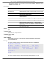
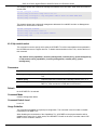
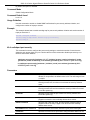
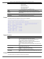
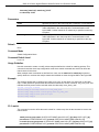
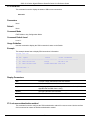
Conventions
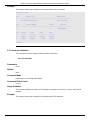
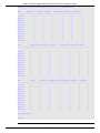
Convention
Description
Boldface Font
Commands, command options and keywords are printed in boldface.
Keywords, in the command line, are to be entered exactly as they are
displayed.
UPPERCASE ITALICS Font
Parameters or values that must be specified are printed in
UPPERCASE ITALICS. Parameters in the command line are to be
replaced with the actual values that are desired to be used with the
command.
Square Brackets [ ]
Square brackets enclose an optional value or set of optional
arguments.
Braces { }
Braces enclose alternative keywords separated by vertical bars.
Generally, one of the keywords in the separated list can be chosen.
Vertical Bar |
Optional values or arguments are enclosed in square brackets and
separated by vertical bars. Generally, one or more of the vales or
arguments in the separated list can be chosen.
Blue Courier Font
This convention is used to represent an example of a screen console
display including example entries of CLI command input with the
corresponding output. All examples used in this manual are based on
the DGS-1510-28P switch.
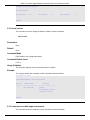
Notes, Notices, and Cautions
Below are examples of the three types of indicators used in this manual. When administering your switch
using the information in this document, you should pay special attention to these indicators. Each
example below provides an explanatory remark regarding each type of indicator.
1
DGS-1510 Series Gigabit Ethernet SmartPro Switch CLI Reference Guide
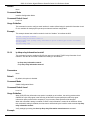
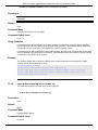
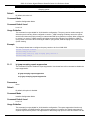
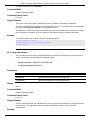
NOTE: A note indicates important information that helps you make better use of your device.
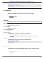
NOTICE: A notice indicates either potential damage to hardware or loss of data and tells you
how to avoid the problem.
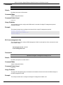
CAUTION: A caution indicates a potential for property damage, personal injury, or death.
Command Descriptions
The information pertaining to each command in this reference guide is presented using a number of
template fields. The fields are:
•
•
•
•
•
•
•
•
Description - This is a short and concise statement describing the commands functionality.
Syntax - The precise form to use when entering and issuing the command.
Parameters - A table where each row describes the optional or required parameters, and their
use, that can be issued with the command.
Default - If the command sets a configuration value or administrative state of the Switch then any
default settings (i.e. without issuing the command) of the configuration is shown here.
Command Mode - The mode in which the command can be issued. These modes are described
in the section titled “Command Modes” below.
Command Default Level – The user privilege level in which the command can be issued.
Usage Guideline - If necessary, a detailed description of the command and its various utilization
scenarios is given here.
Example(s) - Each command is accompanied by a practical example of the command being
issued in a suitable scenario.
Command Modes
There are several command modes available in the command-line interface (CLI). The set of commands
available to the user depends on both the mode the user is currently in and their privilege level. For each
case, the user can see all the commands that are available in a particular command mode by entering a
question mark (?) at the system prompt.
The command-line interface has five pre-defined privilege levels:
•
•
•
•
Basic User - Privilege Level 1. This user account level has the lowest priority of the user
accounts. The purpose of this type of user account level is for basic system checking.
Advanced User - Privilege Level 3. This user account level is allowed to configure the terminal
control setting. This user account can only show limited information that is not related to security.
Power User - Privilege 8. This user account level can execute fewer commands than operator,
including configuration commands other than the operator level and administrator level
commands.
Operator - Privilege Level 12. This user account level is used to grant system configuration rights
for users who need to change or monitor system configuration, except for security related
information such as user accounts and SNMP account settings, etc.
2
DGS-1510 Series Gigabit Ethernet SmartPro Switch CLI Reference Guide
•
Administrator - Privilege Level 15. This administrator user account level can monitor all system
information and change any of the system configuration settings expressed in this configuration
guide.
The command-line interface has a number of command modes. There are three basic command modes:
•
•
•
User EXEC Mode
Privileged EXEC Mode
Global Configuration Mode
All other sub-configuration modes can be accessed via the Global Configuration Mode.
When a user logs in to the Switch, the privilege level of the user determines the command mode the user
will enter after initially logging in. The user will either log into User EXEC Mode or the Privileged EXEC
Mode.
•
•
Users with a basic user level will log into the Switch in the User EXEC Mode.
Users with advanced user, power-user, operator or administrator level accounts will log into the
Switch in the Privileged EXEC Mode.
Therefore, the User EXEC Mode can operate at a basic user level and the Privileged EXEC Mode can
operate at the advanced user, power-user, operator, or administrator levels. The user can only enter the
Global Configuration Mode from the Privileged EXEC Mode. The Global Configuration Mode can be
accessed by users who have operator or administrator level user accounts.
As for sub-configuration modes, a subset of those can only be accessed by users who have the highest
secure administrator level privileges.
The following table briefly lists the available command modes. Only the basic command modes and some
of the sub-configuration modes are enumerated. The basic command modes and basic sub-configuration
modes are further described in the following chapters. Descriptions for the rest of the sub-configuration
modes are not provided in this section. For more information on the additional sub-configuration modes,
the user should refer to the chapters relating to these functions.
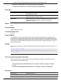
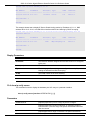
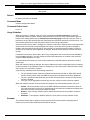
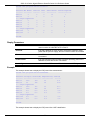
The available command modes and privilege levels are described below:
Command Mode/
Purpose
Privilege Level
User EXEC Mode /
Basic User level
This level has the lowest priority of the user accounts. It is provided only
to check basic system settings.
Privileged EXEC Mode /
Advanced User level
This level is allowed to configure the terminal control setting. This user
account can only show limited information that is not related to security.
Privileged EXEC Mode /
Power User level
This level can execute less commands than operator, include the
configure commands other than the operator level and administrator
level commands.
Privileged EXEC Mode /
Operator level
For changing both local and global terminal settings, monitoring, and
performing certain system administration tasks. The system
administration tasks that can be performed at this level except for any
security related information.
Privileged EXEC Mode /
This level is identical to privileged EXEC mode at the operator level,
3
DGS-1510 Series Gigabit Ethernet SmartPro Switch CLI Reference Guide
Administrator level
except that a user at the administrator level can monitor and clear
security related settings.
Global Configuration Mode /
Operator level
For applying global settings, except for security related settings, on the
entire switch. In addition to applying global settings on the entire switch,
the user can access other sub-configuration modes from global
configuration mode.
Global Configuration Mode /
Administrator level
For applying global settings on the entire switch. In addition to applying
global settings on the entire switch, the user can access other subconfiguration modes from global configuration mode.
Interface Configuration Mode
/ Administrator level
For applying interface related settings.
VLAN Interface Configuration
Mode
For applying VLAN interface related settings.
VLAN Configuration Mode
For applying settings to a VLAN.
IP Access-List Configuration
Mode
For specifying filtering criteria for an IP access list.
User EXEC Mode at Basic User Level
This command mode is mainly designed for checking basic system settings. This command mode can be
entered by logging in as a basic user.
Privileged EXEC Mode at Advanced User Level
This command mode is mainly designed for checking basic system settings, allowing users to change the
local terminal session settings and carrying out basic network connectivity verification. One limitation of
this command mode is that it cannot be used to display information related to security. This command
mode can be entered by logging in as an advanced user.
Privileged EXEC Mode at Power User Level
User logged into the Switch in privileged EXEC mode at this level can execute fewer commands than
operator, including the configuration commands other than the operator level and administrator level
commands. The method to enter privileged EXEC mode at power user level is to login to the Switch with
a user account that has a privileged level of 8.
Privileged EXEC Mode at Operator Level
Users logged into the Switch in privileged EXEC mode at this level can change both local and global
terminal settings, monitor, and perform system administration tasks (except for security related
information). The method to enter privileged EXEC mode at operator level is to login to the Switch with a
user account that has a privilege level of 12.
Privileged EXEC Mode at Administrator Level
This command mode has a privilege level of 15. Users logged in with this command mode can monitor all
system information and change any system configuration settings mentioned in this Configuration Guide.
The method to enter privileged EXEC mode at administrator level is to login to the Switch with a user
account that has a privilege level of 15.
Global Configuration Mode
The primary purpose of the global configuration mode is to apply global settings on the entire switch.
Global configuration mode can be accessed at operator or administrator level user accounts. However,
security related settings are not accessible at operator user account. In addition to applying global
settings on the entire switch, the user can also access other sub-configuration modes. In order to access
the global configuration mode, the user must be logged in with the corresponding account level and use
the configure terminal command in the privileged EXEC mode.
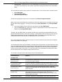
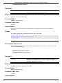
In the following example, the user is logged in as an Administrator in the Privileged EXEC Mode and uses
the configure terminal command to access the Global Configuration Mode:
4
DGS-1510 Series Gigabit Ethernet SmartPro Switch CLI Reference Guide
Switch# configure terminal
Switch(config)#
The exit command is used to exit the global configuration mode and return to the privileged EXEC mode.
Switch(config)# exit
Switch#
The procedures to enter the different sub-configuration modes can be found in the related chapters in this
Configuration Guide. The command modes are used to configure the individual functions.
Interface Configuration Mode
Interface configuration mode is used to configure the parameters for an interface or a range of interfaces.
An interface can be a physical port, VLAN, or other virtual interface. Thus, interface configuration mode is
distinguished further according to the type of interface. The command prompt for each type of interface is
slightly different.
VLAN Interface Configuration Mode
VLAN interface configuration mode is one of the available interface modes and is used to configure the
parameters of a VLAN interface.
To access VLAN interface configuration mode, use the following command in global configuration mode:
Switch(config)# interface vlan 1
Switch(config-if)#
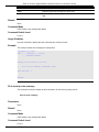
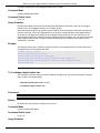
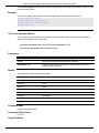
Creating a User Account
By default, there is no user account created on this switch. For security reasons, it is highly recommended
to create user accounts to manage and control access to this switch’s interface. This section will assist a
user with creating a user account by means of the Command Line Interface.
Observe the following example.
Switch>enable
Switch#configure terminal
Switch(config)#username admin password admin
Switch(config)#username admin privilege 15
Switch(config)#line console
Switch(config-line)#login local
Switch(config-line)#
In the above example we had to navigate and access the username command.
•
•
•
•
•
Starting in the User EXEC Mode we enter the command enable to access the Privileged EXEC
Mode.
After accessing the Privileged EXEC Mode, we entered the command configure terminal to
access the Global Configuration Mode. The username command can be used in the Global
Configuration Mode.
The command username admin password admin creates a user account with the username of
admin and a password of admin.
The command username admin privilege 15 assigns a privilege level value of 15 to the user
account admin.
The command line console allows us to access the console interface’s Line Configuration Mode.
5
DGS-1510 Series Gigabit Ethernet SmartPro Switch CLI Reference Guide
•
The command login local tell the Switch that users need to enter locally configured login
credentials to access the console interface.
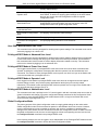
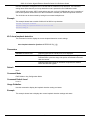
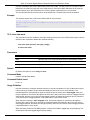
Save the running configuration to the start-up configuration. This means to save the changes made so
that when the Switch is rebooted, the configuration will not be lost. The following example shows how to
save the running configuration to the start-up configuration.
Switch#copy running-config
startup-config
Destination filename startup-config? [y/n]:
y
Saving all configurations to NV-RAM.......... Done.
Switch#
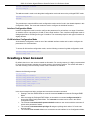
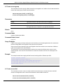
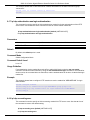
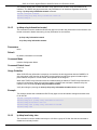
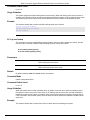
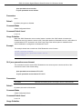
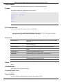
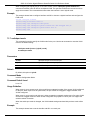
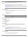
After the Switch was rebooted, or when the users logs out and back in, the newly created username and
password must be entered to access the CLI interface again, as seen below.
DGS-1510-28P Gigabit Ethernet SmartPro Switch
Command Line Interface
Firmware: Build 1.00.016
Copyright(C) 2014 D-Link Corporation. All rights reserved.
User Access Verification
Username:admin
Password:*****
Switch#
Interface Notation
When configuration the physical ports available on this switch, a specific interface notation is used. The
following will explain the layout, terminology and use of this notation.
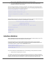
In the following example, we’ll enter the Global Configuration Mode and then enter the Interface
Configuration Mode, using the notation 1/0/1. After entering the Interface Configuration Mode for port 1,
we’ll change the speed to 1 Gbps, using the speed 1000 command.
Switch# configure terminal
Switch(config)# interface Ethernet 1/0/1
Switch(config-if)# speed 1000
Switch(config-if)#
In the above example the notation 1/0/1 was used. The terminology for each parameter is as follows:
•
Interface Unit’s ID / Open Slot’s ID / Port’s ID
The Interface Unit’s ID is the ID of the stacking unit without the physical stack. If stacking is disabled or
this unit is a stand-alone unit, then this parameter is irrelevant. The Open Slot’s ID is the ID of the module
plugged into the open module slot of the Switch. The DGS-1510 Series doesn’t support any open
6
DGS-1510 Series Gigabit Ethernet SmartPro Switch CLI Reference Guide
modules slots, thus this parameters will always by zero for this switch series. Lastly, the Port’s ID is the
physical port number of the port being configured.
In summary the above example will configure the stacked switch with the ID of 1, with the open slot ID of
0, and the physical port number 1.
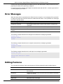
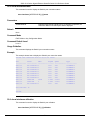
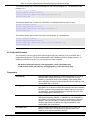
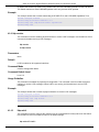
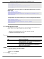
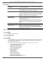
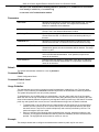
Error Messages
When the users issue a command that the Switch does not recognize, error messages will be generated
to assist users with basic information about the mistake that was made. A list of possible error messages
are found in the table below.
Error Message
Meaning
Ambiguous command
Not enough keywords were entered for the Switch to recognize the
command.
Incomplete command
The command was not entered with all the required keyword.
Invalid input detected at
^marker
The command was entered incorrectly.
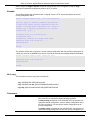
The following example shows how an ambiguous command error message is generated.
Switch# show v
Ambiguous command
Switch#
The following example shows how an incomplete command error message is generated.
Switch# show
Incomplete command
Switch#
The following example shows how an invalid input error message is generated.
Switch# show verb
^
Invalid input detected at ^marker
Switch#
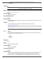
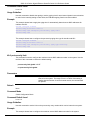
Editing Features
The command line interface of this switch supports to following keyboard keystroke editing features.
Keystroke
Description
Delete
Deletes the character under the cursor and shifts the remainder of the
line to the left.
Backspace
Deletes the character to the left of the cursor and shifts the remainder
of the line to the left.
Left Arrow
Moves the cursor to the left.
Right Arrow
Moves the cursor to the right.
7
DGS-1510 Series Gigabit Ethernet SmartPro Switch CLI Reference Guide
CTRL+R
Toggles the insert text function on and off. When on, text can be
inserted in the line and the remainder of the text will be shifted to the
right. When off, text can be inserted in the line and old text will
automatically be replaced with the new text.
Return
Scrolls down to display the next line or used to issue a command.
Space
Scrolls down to display the next page.
ESC
Escapes from the displaying page.
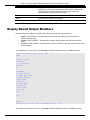
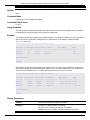
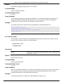
Display Result Output Modifiers
Results displayed by show commands can be filtered using the following parameters:
•
•
•
begin FILTER-STRING - This parameter is used to start the display with the first line that
matches the filter string.
include FILTER-STRING - This parameter is used to display all the lines that match the filter
string.
exclude FILTER-STRING - This parameter is used to exclude the lines that match the filter string
from the display.
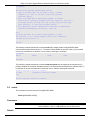
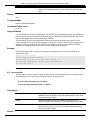
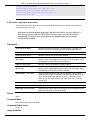
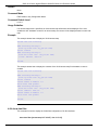
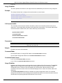
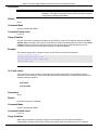
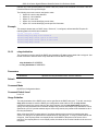
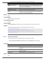
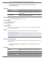
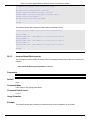
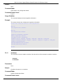
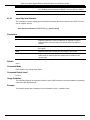
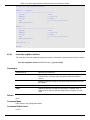
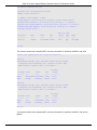
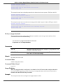
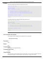
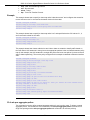
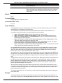
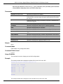
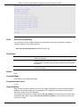
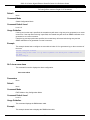
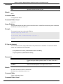
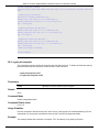
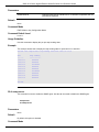
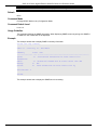
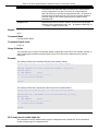
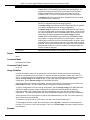
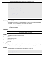
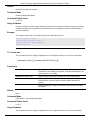
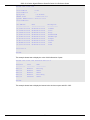
The example below shows how to use the begin FILTER-STRING parameter in a show command.
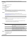
Switch#show running-config | begin # AAA
# AAA
configure terminal
# AAA START
no aaa new-model
# AAA END
end
# PRIVMGMT
configure terminal
# COMMAND LEVEL START
# COMMAND LEVEL END
# LEVEL START
# LEVEL END
# ACCOUNT START
# ACCOUNT END
# LOGIN START
# LOGIN END
end
# CLI
# BASIC
CTRL+C ESC q Quit SPACE n Next Page ENTER Next Entry a All
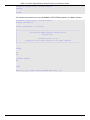
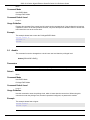
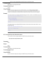
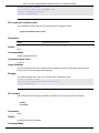
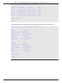
The example below shows how to use the include FILTER-STRING parameter in a show command.
8
DGS-1510 Series Gigabit Ethernet SmartPro Switch CLI Reference Guide
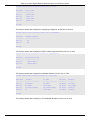
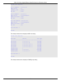
Switch#show running-config | include # DEVICE
# DEVICE
Switch#
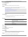
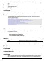
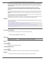
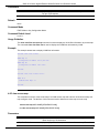
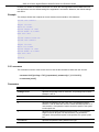
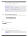
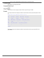
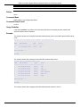
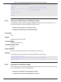
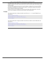
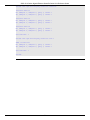
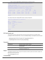
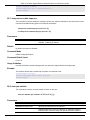
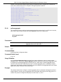
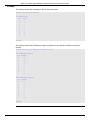
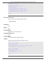
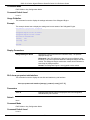
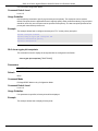
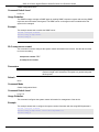
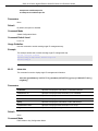
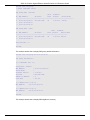
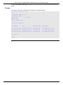
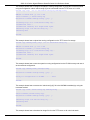
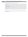
The example below shows how to use the exclude FILTER-STRING parameter in a show command.
Switch#show running-config | exclude # DEVICE
Building configuration...
Current configuration : 34703 bytes
#------------------------------------------------------------------------------#
DGS-1510-28P Gigabit Ethernet SmartPro Switch
#
Configuration
#
#
Firmware: Build 1.00.013
#
Copyright(C) 2014 D-Link Corporation. All rights reserved.
#-------------------------------------------------------------------------------
# STACK
end
end
configure terminal
end
# AAA
CTRL+C ESC q Quit SPACE n Next Page ENTER Next Entry a All
9
DGS-1510 Series Gigabit Ethernet SmartPro Switch CLI Reference Guide
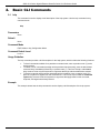
2.
Basic CLI Commands
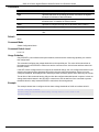
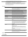
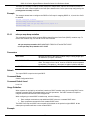
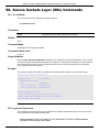
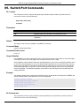
2-1 help
This command is used to display a brief description of the help system. Use the help command in any
command mode.
help
Parameters
None.
Default
None.
Command Mode
EXEC Mode or Any Configuration Mode.
Command Default Level
Level: 1.
Usage Guideline
The help command provides a brief description for the help system, which includes the following functions:
•
•
•
To list all commands available for a particular command mode, enter a question mark (?) at the
system prompt.
To obtain a list of commands that begin with a particular character string, enter the abbreviated
command entry immediately followed by a question mark (?). This form of help is called word
help, because it lists only the keywords or arguments that begin with the abbreviation entered.
To list the keywords and arguments associated with a command, enter a question mark (?) in
place of a keyword or argument on the command line. This form of help is called the command
syntax help, because it lists the keywords or arguments that apply based on the command,
keywords, and arguments already entered.
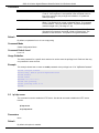
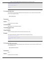
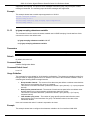
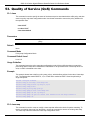
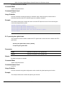
Example
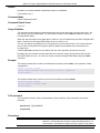
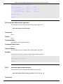
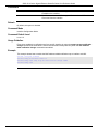
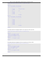
This example shows how the help command is used to display a brief description of the help system.
10
DGS-1510 Series Gigabit Ethernet SmartPro Switch CLI Reference Guide
Switch#help
The switch CLI provides advanced help feature.
1. Help is available when you are ready to enter a command
argument (e.g. 'show ?') and want to know each possible
available options.
2. Help is provided when an abbreviated argument is entered
and you want to know what arguments match the input(e.g. 'show ve?'.).
If nothing matches, the help list will be empty and you must backup
until entering a '?' shows the available options.
3. For completing a partial command name could enter the abbreviated
command name immediately followed by a <Tab> key.
Note:
Since the character '#' is used for help purpose, to enter
the character '?' in a string argument, press ctrl+v immediately
followed by the character '?'.
Switch#
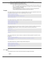
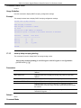
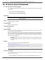
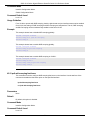
The following example shows how to use the word help to display all the Privileged EXEC Mode
commands that begin with the letters “re”. The letters entered before the question mark (?) are reprinted
on the next command line to allow the user to continue entering the command.
Switch#re?
reboot
rename
renew
reset
Switch#re
The following example shows how to use the command syntax help to display the next argument of a
partially complete IP access-list standard command. The characters entered before the question mark (?)
is reprinted on the next command line to allow the user to continue entering the command.
Switch(config)#ip access-list standard ?
<1-1999>
Standard IP access-list number
<cr>
Switch(config)#ip access-list standard
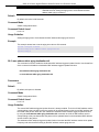
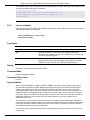
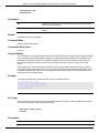
2-2 enable
This command is used to enter the Privileged EXEC Mode.
enable [PRIVILEGE-LEVEL]
Parameters
PRIVILEGE-LEVEL
(Optional) Specifies to set the privilege level for the user. The privilege
level is between 1 and 15. If not specified, level 15 will be used.
Default
11
DGS-1510 Series Gigabit Ethernet SmartPro Switch CLI Reference Guide
None.
Command Mode
User EXEC Mode.
Privilege EXEC Mode.
Command Default Level
Level: 1.
Usage Guideline
Execute this command if the current level is lower than the command level. If the privileged level requires
a password, enter it in the field provided. However, only three attempts are allowed. Failure to access this
level returns the user to the current level.
Example
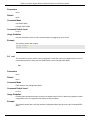
This example shows how to enter the Privileged EXEC Mode.
Switch# enable 15
password:***
Switch#
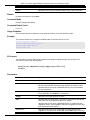
2-3 disable
This command is used to downgrade to a level lower user level than the privileged level.
disable [PRIVILEGE-LEVEL]
Parameters
PRIVILEGE LEVEL
Specifies the privilege level to enter. If not specified, level 1 is used.
Default
None.
Command Mode
User EXEC Mode.
Privilege EXEC Mode.
Command Default Level
Level: 1.
Usage Guideline
Use this command to enter the privilege level, which is lower than the current level. When using this
command to enter the privilege level, that has a password configured, no password is needed.
Example
This example shows how to logout.
Switch# disable
Switch# logout
12
DGS-1510 Series Gigabit Ethernet SmartPro Switch CLI Reference Guide
2-4 configure terminal
This command is used to enter the Global Configuration Mode.
configure terminal
Parameters
None.
Default
None
Command Mode
Privilege EXEC Mode.
Command Default Level
Level: 12.
Usage Guideline
This command is used to enter the Global Configuration Mode.
Example
This example shows how to enter into Global Configuration Mode.
Switch# configure terminal
Switch(config)#
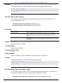
2-5 login (EXEC)
This command is used to configure a login username.
login
Parameters
None.
Default
None.
Command Mode
User EXEC Mode.
Privileged EXEC Mode.
Command Default Level
Level: 1.
Usage Guideline
Use this command to change the login account. Three attempts are allowed to login to the Switch’s
interface. When using Telnet, if all attempts fail, access will return to the command prompt. If no
information is entered within 60 seconds, the session will return to the state when logged out.
13
DGS-1510 Series Gigabit Ethernet SmartPro Switch CLI Reference Guide
Example
This example shows how to login with username “user1”.
Switch# login
Username: user1
Password: xxxxx
Switch#
2-6 login (Line)
This command is used to set the line login method. Use the no form of the command to disable the login.
login [local]
no login
Parameters
login
Specifies that the line login method will be login.
local
Specifies that the line login method will be local.
Default
By default, there is no login details configured for the console line.
By default, there is a login method (by password) configured for the Telnet line.
By default, there is a login local method (by username and password) configured for the SSH line.
Command Mode
Line Configuration Mode.
Command Default Level
Level: 15.
Usage Guideline
For Console and Telnet access, when AAA is enabled, the line uses rules configured by the AAA module.
When AAA is disabled, the line uses the following authentication rules:
•
•
•
When login is disabled, the user can enter the line at Level 1.
When the by password option is selected, after inputting the same password as the command
password, the user enter the line at level 1. If the password wasn’t previously configured an error
message will be displayed and the session will be closed.
When the username and password option is selected, enter the username and password
configured by the username command.
For SSH access, there are three authentication types:
•
•
•
SSH public key,
Host-based authentication, and
Password authentication.
The SSH public key and host-based authentication types are independent from the login command in the
line mode. If the authentication type is password, the following rules apply:
14
DGS-1510 Series Gigabit Ethernet SmartPro Switch CLI Reference Guide
•
•
When AAA is enabled, the AAA module is used.
When AAA is disabled, the following rules are used:
o When login is disabled, the username and password is ignored. Enter the details at Level
1.
o When the username and password option is selected, use the username and password
setup by the username command.
o When the password option is selected, the username is ignored but a password is
required using the password command to enter the line at level 1.
Example
This example shows how to enter the Line Configuration Mode and to create a password for the line user.
This password only takes effect once the corresponding line is set to login.
Switch# configure terminal
Switch(config)# line console
Switch(config-line)# password loginpassword
Switch(config-line)#
This example shows how to configure the line console login method as “login”.
Switch# configure terminal
Switch(config)# line console
Switch(config-line)# login
Switch(config-line)#
This example shows how to enter the login command. The device will check the validity of the user from
the password create command. If correct, the user will have access at the particular level.
Switch#login
Password:*************
Switch#
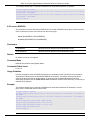
This example shows how to create a username “useraccount” with the password of “pass123” and use
Privilege 12.
Switch# configure terminal
Switch(config)# username useraccount privilege 12 password 0 pass123
Switch(config)#
This example shows how to configure the login method as login local.
Switch# configure terminal
Switch(config)# line console
Switch(config-line)# login local
Switch(config-line)#
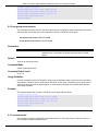
2-7 logout
This command is used to close an active terminal session by logging off the Switch.
logout
15
DGS-1510 Series Gigabit Ethernet SmartPro Switch CLI Reference Guide
Parameters
None.
Default
None.
Command Mode
User EXEC Mode.
Privilege EXEC Mode.
Command Default Level
Level:1.
Usage Guideline
Use this command to close an active terminal session by logging out of the device.
Example
This example shows how to logout
Switch# disable
Switch# logout
2-8 end
This command is used to end the current configuration mode and return to the highest mode in the CLI
mode hierarchy which is either the User EXEC Mode or the Privileged EXEC Mode.
end
Parameters
None.
Default
None.
Command Mode
EXEC Mode or Any Configuration Mode.
Command Default Level
Level: 1.
Usage Guideline
Executing this command will return access to the highest mode in the CLI hierarchy regardless of what
configuration mode or configuration sub-mode currently located at.
Example
This example shows how to end the Interface Configuration Mode and go back to the Privileged EXEC
Mode.
16
DGS-1510 Series Gigabit Ethernet SmartPro Switch CLI Reference Guide
Switch# configure terminal
Switch(config)# interface eth1/0/1
Switch(config-if)#end
Switch#
2-9 exit
This command is used to end the configuration mode and go back to the last mode. If the current mode is
the User EXEC Mode or the Privilege EXEC Mode, executing the exit command logs you out of the
current session.
exit
Parameters
None.
Default
None.
Command Mode
EXEC Mode or Any Configuration Mode.
Command Default Level
Level: 1.
Usage Guideline
Use this command to exit the current configuration mode and go back to the last mode. When the user is
in the User EXEC Mode or the Privilege EXEC Mode, this command will logout the session.
Example
This example shows how to exit from the Interface Configuration Mode and return to the Global
Configuration Mode.
Switch# configure terminal
Switch(config) interface eth1/0/1
Switch(config-if)#exit
Switch(config)#
2-10 show history
This command is used to list the commands entered in the current EXEC Mode session.
show history
Parameters
None.
Default
None.
17
DGS-1510 Series Gigabit Ethernet SmartPro Switch CLI Reference Guide
Command Mode
EXEC Mode or Any Configuration Mode.
Command Default Level
Level: 1.
Usage Guideline
Commands entered are recorded by the system. A recorded command can be recalled by pressing
CTRL+P or the Up Arrow key which will recall previous commands in sequence. The history buffer size is
fixed at 20 commands.
The function key instructions, below, displays how to navigate the command in the history buffer.
•
•
CTRL+P or the Up Arrow key - Recalls commands in the history buffer, beginning with the most
recent command. Repeat the key sequence to recall successively older commands.
CTRL+N or the Down Arrow key - Returns to more recent commands in the history buffer after
recalling commands with Ctrl-P or the Up Arrow key. Repeat the key sequence to recall
successively more recent commands.
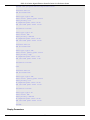
Example
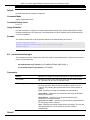
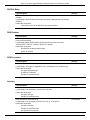
This example shows how to display the command buffer history.
Switch# show history
help
history
Switch#
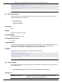
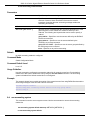
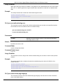
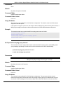
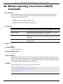
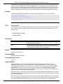
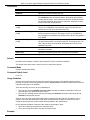
2-11 show environment
This command is used to display fan, temperature, power availability and status information.
show environment [fan | power | temperature]
Parameters
fan
(Optional) Specifies to display the Switch fan detailed status.
power
(Optional) Specifies to display the Switch power detailed status.
temperature
(Optional) Specifies to display the Switch temperature detailed status.
Default
None.
Command Mode
EXEC Mode or Any Configuration Mode.
Command Default Level
Level: 1.
Usage Guideline
If a specific type is not specified, all types of environment information will be displayed.
18
DGS-1510 Series Gigabit Ethernet SmartPro Switch CLI Reference Guide
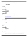
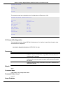
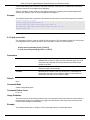
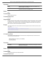
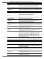
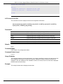
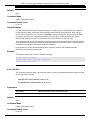
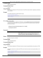
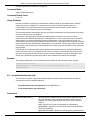
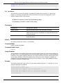
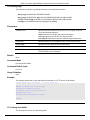
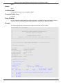
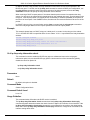
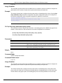
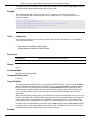
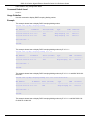
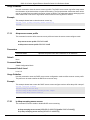
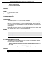
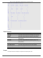
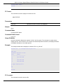
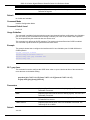
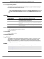
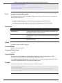
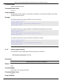
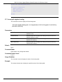
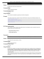
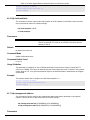
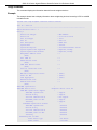
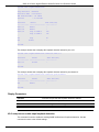
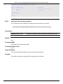
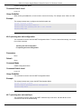
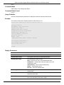
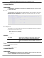
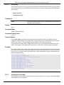
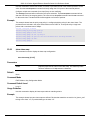
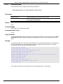
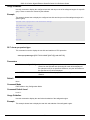
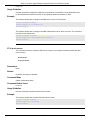
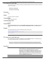
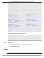
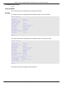
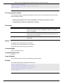
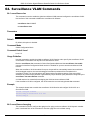
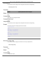
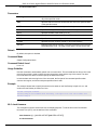
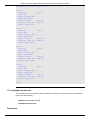
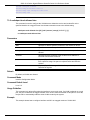
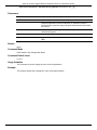
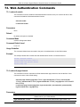
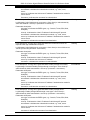
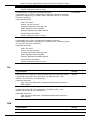
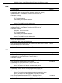
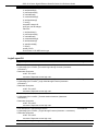
Example
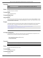
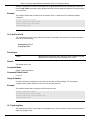
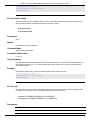
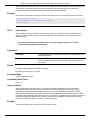
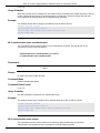
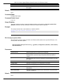
This example shows how to display fan, temperature, power availability and status information.
Switch#show environment
Detail Temperature Status:
Unit
Temperature Descr/ID
Current/Threshold Range
---------------------------------------------------------1
Central Temperature/1
27C/11~79C
Status code: * temperature is out of threshold range
Detail Fan Status:
-------------------------------------------------------------Right Fan 1 (OK)
Right Fan 2 (OK)
Detail Power Status:
Unit
Power Module
-------------------1
Power 1
Power Status
------------in-operation
Switch#
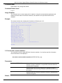
Display Parameters
Power status
in-operation: The power rectifier is in normal operation.
failed: The power rectifier not working normally.
empty: The power rectifier is not installed.
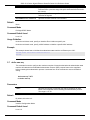
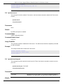
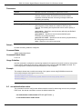
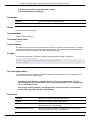
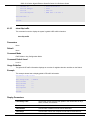
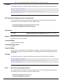
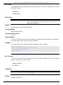
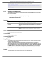
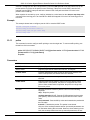
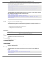
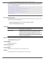
2-12 show unit
This command is used to display information about system units.
show unit [UNIT-ID]
Parameters
UNIT-ID
(Optional) Specify the unit to display.
Default
None.
Command Mode
EXEC Mode or Any Configuration Mode.
Command Default Level
Level: 1.
Usage Guideline
This command displays information about the system modules. If no option is specified, then all of units’
information will be displayed.
19
DGS-1510 Series Gigabit Ethernet SmartPro Switch CLI Reference Guide
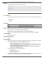
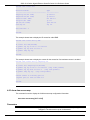
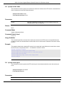
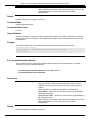
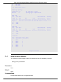
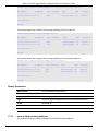
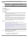
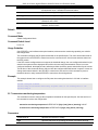
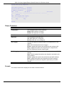
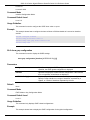
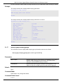
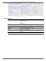
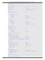
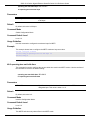
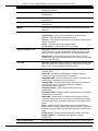
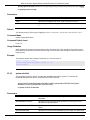
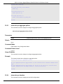
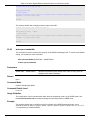
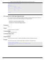
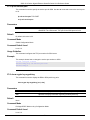
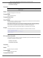
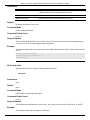
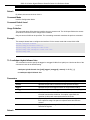
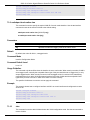
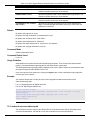
Example
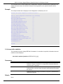
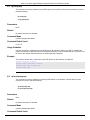
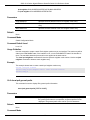
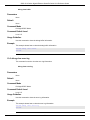
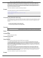
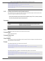
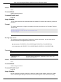
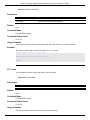
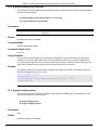
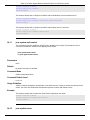
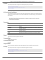
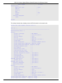
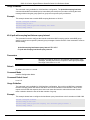
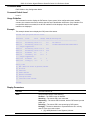
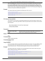
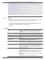
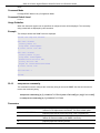
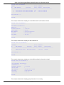
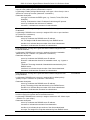
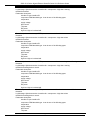
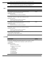
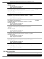
This example shows how to display the information about units on a system.
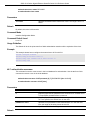
Switch#show unit
Unit
---1
Model Descr
------------------------------------------No module description
Unit
---1
Serial-Number
---------------------------------
Unit
---1
1
Memory
-------DRAM
FLASH
Total
---------131072 K
29937 K
Used
---------66567 K
7799 K
Status
--------ok
Model Name
-----------------DGS-1510-28P
Up Time
----------------0DT6H32M18S
Free
---------64505 K
22138 K
Switch#
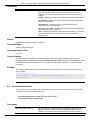
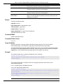
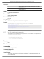
2-13 show cpu utilization
This command is used to display the CPU utilization information.
show cpu utilization
Parameters
None.
Default
None.
Command Mode
EXEC Mode or Any Configuration Mode.
Command Default Level
Level: 1.
Usage Guideline
This command displays the system’s CPU utilization information in 5 second, 1 minute, and 5 minute
intervals.
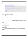
Example
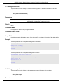
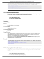
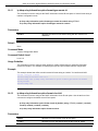
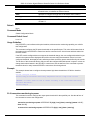
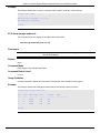
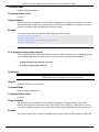
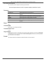
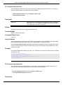
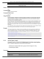
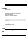
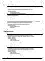
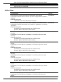
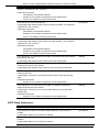
This example shows how to display the information about CPU utilization.
20
DGS-1510 Series Gigabit Ethernet SmartPro Switch CLI Reference Guide
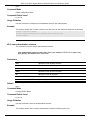
Switch#show cpu utilization
CPU Utilization
Five seconds -
8 %
One minute -
7 %
Five minutes -
Switch#
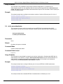
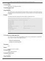
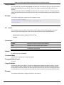
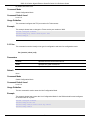
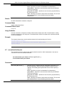
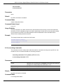
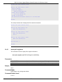
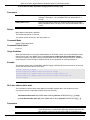
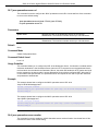
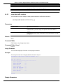
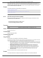
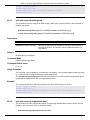
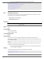
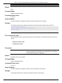
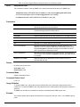
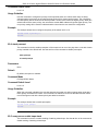
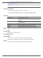
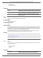
2-14 show version
This command is used to display the Switch’s software version information.
show version
Parameters
None.
Default
None.
Command Mode
EXEC Mode or Any Configuration Mode.
Command Default Level
Level: 1.
Usage Guideline
This command displays version information about the Switch.
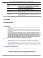
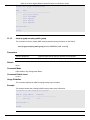
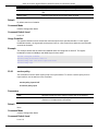
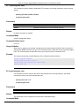
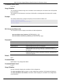
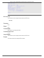
Example
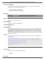
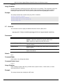
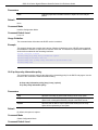
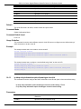
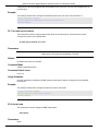
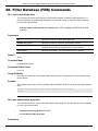
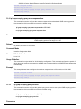
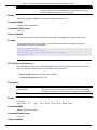
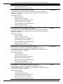
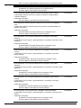
This example shows how to displays version information about the Switch.
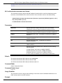
Switch#show version
System MAC Address: 00-01-02-03-04-00
Unit ID
------1
Module Name
-----------------DGS-1510-28P
Versions
--------------------H/W:A1
Bootloader:1.00.006
Runtime:1.00.016
Switch#
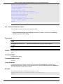
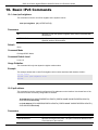
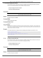
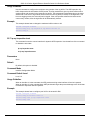
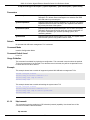
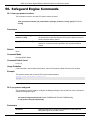
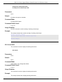
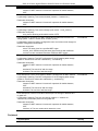
2-15 snmp-server enable traps environment
This command is used to enable the power, temperature and fan trap state.
21
7 %
DGS-1510 Series Gigabit Ethernet SmartPro Switch CLI Reference Guide
snmp-server enable traps environment [fan] [power] [temperature]
no snmp-server enable traps environment [fan] [power] [temperature]
Parameters
fan
(Optional) Specifies to enable the fan trap state for warning fan event
(fan failed or fan recover).
power
(Optional) Specifies to enable the power trap state for warning power
event (power failed or power recover).
temperature
(Optional) Specifies to enable the temperature trap state for warning
temperature event (temperature exceeds the thresholds or
temperature recover).
Default
None.
Command Mode
Global Configuration Mode.
Command Default Level
Level: 12.
Usage Guideline
This command is used to configure the environment temperature threshold which corresponds to the
normal range of the temperature defined for the sensor. The low threshold must be smaller than the high
threshold. The configured range must fall within the operational range which corresponds to the minimum
and maximum allowed temperatures defined for the sensor. When the configured threshold is crossed, a
notification will be sent.
Example
This example shows how to configure the environment temperature thresholds for thermal sensor ID 1 on
unit 1.
Switch# configure terminal
Switch(config)# environment temperature threshold unit 1 thermal 1 high 100 low 20
Switch(config)#
2-16 environment temperature threshold
This command is used to configure the environment temperature thresholds. Use the no form of the
command to reset to the default setting.
environment temperature threshold unit UNIT-ID thermal THREMAL-ID [high VALUE] [low
VALUE]
no environment temperature threshold unit UNIT-ID thermal THREMAL-ID [high] [low]
Parameters
unit UNIT-ID
Specifies the unit ID.
thermal THERMAL-ID
Specifies the thermal sensor’s ID.
22
DGS-1510 Series Gigabit Ethernet SmartPro Switch CLI Reference Guide
high
(Optional) Specifies the high threshold of the temperature in Celsius.
The range is from -100 to 200.
low
(Optional) Specifies the low threshold of the temperature in Celsius.
The range is from -100 to 200. The low threshold must be smaller than
the high threshold.
Default
None.
Command Mode
Global Configuration Mode.
Command Default Level
Level: 12.
Usage Guideline
This command is used to configure the environment temperature threshold which corresponds to the
normal range of the temperature defined for the sensor. The low threshold must be smaller than the high
threshold. The configured range must fall within the operational range which corresponds to the minimum
and maximum allowed temperatures defined for the sensor. When the configured threshold is crossed, a
notification will be sent.
Example
This example shows how to configure the environment temperature thresholds for thermal sensor ID 1 on
unit 1.
Switch# configure terminal
Switch(config)# environment temperature threshold unit 1 thermal 1 high 100 low 20
Switch(config)#
23
DGS-1510 Series Gigabit Ethernet SmartPro Switch CLI Reference Guide
3.
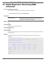
802.1X Commands
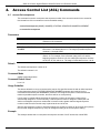
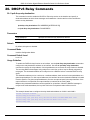
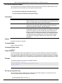
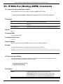
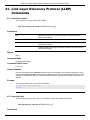
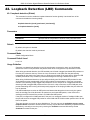
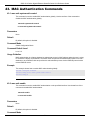
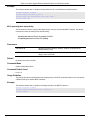
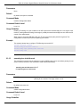
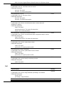
3-1 clear dot1x counters
This command is used to clear 802.1X counters (diagnostics, statistics and session statistics).
clear dot1x counters {all | interface INTERFACE-ID [, | -]}
Parameters
all
Specifies to clear 802.1X counters (diagnostics, statistics and session
statistics) on all interfaces.
interface INTERFACE-ID
Specifies to clear 802.1X counters (diagnostics, statistics and session
statistics) on the specified interface. Valid interfaces are physical ports
(including type, stack member, and port number).
,
(Optional) Specifies a series of interfaces, or separate a range of
interfaces from a previous range. No space is allowed before and after
the comma.
-
(Optional) Specifies a range of interfaces. No space is allowed before
and after the hyphen.
Default
None.
Command Mode
Privileged EXEC Mode.
Command Default Level
Level: 12.
Usage Guideline
This command is used to clear 802.1X counters (diagnostics, statistics and session statistics).
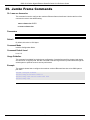
Example
This example shows how to clear 802.1X counters (diagnostics, statistics and session statistics) on the
Ethernet port 1/0/1.
Switch# clear dot1x counters interface eth1/0/1
Switch#
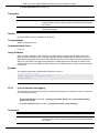
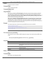
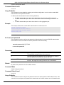
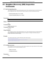
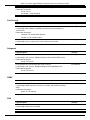
3-2 dot1x control-direction
This command is used to configure the direction of the traffic on a controlled port as unidirectional (in) or
bidirectional (both). Use the no form of the command to reset to the default setting.
dot1x control-direction {both | in}
no dot1x control-direction
Parameters
24
DGS-1510 Series Gigabit Ethernet SmartPro Switch CLI Reference Guide
both
Specifies to enable bidirectional control for the port.
in
Specifies to enable in direction control for the port.
Default
By default, this option is bidirectional mode.
Command Mode
Interface Configuration Mode.
Command Default Level
Level: 12.
Usage Guideline
This command is only available for physical port interface configuration. If the port control is set to forceauthorized, then the port is not controlled in both directions. If the port control is set to auto, then the
access to the port for the controlled direction needs to be authenticated. If the port control is set to forceunauthorized, then the access to the port for the controlled direction is blocked.
Suppose that port control is set to auto. If the control direction is set to both, then the port can receive
and transmit EAPOL packets only. All user traffic is blocked before authentication. If the control direction
is set to in, then in addition to receiving and transmitting EAPOL packets, the port can transmit user traffic
but not receive user traffic before authentication.
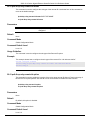
Example
This example shows how to configure the controlled direction of the traffic through Ethernet eth1/0/1 as
unidirectional.
Switch# configure terminal
Switch(config)# interface eth1/0/1
Switch(config-if)# dot1x control-direction in
Switch(config-if)#
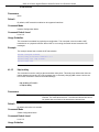
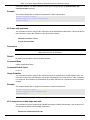
3-3 dot1x default
This command is used to reset the IEEE 802.1X parameters on a specific port to their default settings.
dot1x default
Parameters
None.
Default
IEEE 802.1X authentication is disabled.
Control direction is bidirectional (both).
Port control is auto.
Forward PDU on port is disabled.
Maximum request is 2 times.
Server timer is 30 seconds.
Supplicant timer is 30 seconds.
Transmit interval is 30 seconds.
25
DGS-1510 Series Gigabit Ethernet SmartPro Switch CLI Reference Guide
Command Mode
Interface Configuration Mode.
Command Default Level
Level: 12.
Usage Guideline
This command is used to reset all the IEEE 802.1X parameters on a specific port to their default settings.
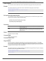
Example
This example shows how to reset the 802.1X parameters on port 1/0/1.
Switch# configure terminal
Switch(config)# interface eth1/0/1
Switch(config-if)# dot1x default
Switch(config-if)#
3-4 dot1x port-control
This command is used to control the authorization state of a port. Use the no command to revert to the
default setting.
dot1x port-control {auto | force-authorized | force-unauthorized}
no dot1x port-control
Parameters
auto
Specifies to enable IEEE 802.1X authentication for the port.
force-authorized
Specifies the port to the force authorized state.
force-unauthorized
Specifies the port to the force unauthorized state.
Default
By default, this option is set as auto.
Command Mode
Interface Configuration Mode.
Command Default Level
Level: 12.
Usage Guideline
This command takes effect only when IEEE 802.1X PAE authenticator is globally enabled by the dot1x
system-auth-control command and is enabled for a specific port by using the dot1x PAE authenticator.
This command is only available for physical port interface configuration.
If the port control is set to force-authorized, then the port is not controlled in both directions. If the port
control is set to auto, then the access to the port for the controlled direction needs to be authenticated. If
the port control is set to force-unauthorized, then the access to the port for the controlled direction is
blocked.
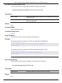
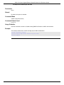
Example
This example shows how to deny all access on Ethernet port 1/0/1.
26
DGS-1510 Series Gigabit Ethernet SmartPro Switch CLI Reference Guide
Switch# configure terminal
Switch(config)# interface eth1/0/1
Switch(config-if)# dot1x port-control force-unauthorized
Switch(config-if)#
3-5 dot1x forward-pdu
This command is used to enable the forwarding of the dot1x PDU. Use the no form of the command to
disable the forwarding of the dot1x PDU.
dot1x forward-pdu
no dot1x forward-pdu
Parameters
None.
Default
By default, this option is disabled.
Command Mode
Interface Configuration Mode.
Command Default Level
Level: 12.
Usage Guideline
This command is only available for physical port interface configuration. This command only takes effect
when the dot1x authentication function is disabled on the receipt port. The received PDU will be
forwarded in either the tagged or untagged form based on the VLAN setting.
Example
This example shows how to configure the forwarding of the dot1x PDU.
Switch# configure terminal
Switch(config)# interface eth1/0/1
Switch(config-if)# dot1x forward-pdu
Switch(config-if)#
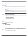
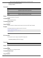
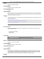
3-6 dot1x initialize
This command is used to initialize the authenticator state machine on a specific port or associated with a
specific MAC address.
dot1x initialize {interface INTERFACE-ID [, | -] | mac-address MAC-ADDRESS}
Parameters
interface INTERFACE-ID
Specifies the port on which the authenticator state machine will be
initialized. Valid interfaces are physical ports.
27
DGS-1510 Series Gigabit Ethernet SmartPro Switch CLI Reference Guide
,
(Optional) Specifies a series of interfaces, or separate a range of
interfaces from a previous range. No space is allowed before and after
the comma.
-
(Optional) Specifies a range of interfaces. No space is allowed before
and after the hyphen.
mac-address MAC-ADDRESS
Specifies the MAC address to be initialized.
Default
None.
Command Mode
Privileged EXEC Mode.
Command Default Level
Level: 12.
Usage Guideline
Under the multi-host mode, specify an interface ID to initialize a specific port.
Under the multi-auth mode, specify a MAC address to initialize a specific MAC address.
Example
This example shows how to initialize the authenticator state machine on Ethernet port 1/0/1.
Switch# dot1x initialize interface eth1/0/1
Switch#
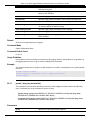
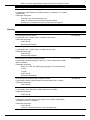
3-7 dot1x max-req
This command is used to configure the maximum number of times that the backend authentication state
machine will retransmit an Extensible Authentication Protocol (EAP) request frame to the supplicant
before restarting the authentication process. Use the no form of the command to reset to the default
setting.
dot1x max-req TIMES
no dot1x max-req
Parameters
TIMES
Specifies the number of times that the Switch retransmits an EAP
frame to the supplicant before restarting the authentication process.
The range is 1 to 10.
Default
By default, this value is 2.
Command Mode
Interface Configuration Mode.
Command Default Level
Level: 12.
28
DGS-1510 Series Gigabit Ethernet SmartPro Switch CLI Reference Guide
Usage Guideline
The command is only available for physical port interface configuration. If no response to an
authentication request from the supplicant within the timeout period (specified by the dot1x timeout txperiod SECONDS command) the Switch will retransmit the request. This command is used to specify the
number of retransmissions.
Example
This example shows how to configure the maximum number of retries on Ethernet port 1/0/1 to be 3.
Switch# configure terminal
Switch(config)# interface eth1/0/1
Switch(config-if)# dot1x max-req 3
Switch(config-if)#
3-8 dot1x pae authenticator
This command is used to configure a specific port as an IEEE 802.1X port access entity (PAE)
authenticator. Use the no form of this command to disable the port as an IEEE 802.1X authenticator.
dot1x pae authenticator
no dot1x pae authenticator
Parameters
None.
Default
By default, this option is disabled.
Command Mode
Interface Configuration Mode.
Command Default Level
Level: 12.
Usage Guideline
This command is only available for physical port interface configuration. Globally enable IEEE 802.1X
authentication on the Switch by using the dot1x system-auth-control command. When IEEE 802.1X
authentication is enabled, the system will authenticate the 802.1X user based on the method list
configured by the aaa authentication dot1x default command.
Example
This example shows how to configure Ethernet port 1/0/1 as an IEEE 802.1X PAE authenticator.
Switch# configure terminal
Switch(config)# interface eth1/0/1
Switch(config-if)# dot1x pae authenticator
Switch(config-if)#
This example shows how to disable IEEE 802.1X authentication on Ethernet port 1/0/1.
29
DGS-1510 Series Gigabit Ethernet SmartPro Switch CLI Reference Guide
Switch# configure terminal
Switch(config)# interface eth1/0/1
Switch(config-if)# no dot1x pae authenticator
Switch(config-if)#
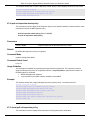
3-9 dot1x re-authenticate
This command is used to re-authenticate a specific port or a specific MAC address.
dot1x re-authenticate {interface INTERFACE-ID [, | -] | mac-address MAC-ADDRESS}
Parameters
interface INTERFACE-ID
Specifies the port to re-authenticate. Valid interfaces are physical
ports.
,
(Optional) Specifies a series of interfaces, or separate a range of
interfaces from a previous range. No space is allowed before and after
the comma.
-
(Optional) Specifies a range of interfaces. No space is allowed before
and after the hyphen.
mac-address MAC-ADDRESS
Specifies the MAC address to re-authenticate.
Default
None.
Command Mode
Privileged EXEC Mode.
Command Default Level
Level: 12.
Usage Guideline
This command is used to re-authenticate a specific port or a specific MAC address.
Example
This example shows how to re-authenticate Ethernet port 1/0/1.
Switch# dot1x re-authenticate interface eth1/0/1
Switch#
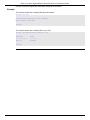
3-10 dot1x system-auth-control
This command is used to globally enable IEEE 802.1X authentication on a switch. Use the no form of this
command to return to disable IEEE 802.1X authentication function.
dot1x system-auth-control
no dot1x system-auth-control
30
DGS-1510 Series Gigabit Ethernet SmartPro Switch CLI Reference Guide
Parameters
None.
Default
By default, this option is disabled.
Command Mode
Global Configuration Mode.
Command Default Level
Level: 12.
Usage Guideline
The 802.1X authentication function restricts unauthorized hosts from accessing the network. Use the
dot1x system-auth-control command to globally enable the 802.1X authentication control. When
802.1X authentication is enabled, the system will authenticate the 802.1X user based on the method list
configured by the aaa authentication dot1x default command.
Example
This example shows how to enable IEEE 802.1X authentication globally on a switch.
Switch# configure terminal
Switch(config)# dot1x system-auth-control
Switch(config)#
3-11 dot1x timeout
This command is used to configure IEEE 802.1X timers. Use the no form of the command to revert a
specific timer setting to the default value.
dot1x timeout {server-timeout SECONDS | supp-timeout SECONDS | tx-period SECONDS}
no dot1x timeout {server-timeout | supp-timeout | tx-period}
Parameters
server-timeout SECONDS
Specifies the number of seconds that the Switch will wait for the
request from the authentication server before timing out the server. On
timeout, authenticator will send EAP-Request packet to client. The
range is 1 to 65535.
supp-timeout SECONDS
Specifies the number of seconds that the Switch will wait for the
response from the supplicant before timing out the supplicant
messages other than EAP request ID. The range is 1 to 65535
tx-period SECONDS
Specifies the number of seconds that the Switch will wait for a
response to an EAP-Request/Identity frame from the supplicant before
retransmitting the request. The range is 1 to 65535
Default
The server-timeout is 30 seconds.
The supp-timeout is 30 seconds.
The tx-period is 30 seconds.
Command Mode
31
DGS-1510 Series Gigabit Ethernet SmartPro Switch CLI Reference Guide
Interface Configuration Mode.
Command Default Level
Level: 12.
Usage Guideline
This command is only available for physical port interface configuration.
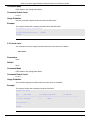
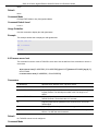
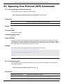
Example
This example shows how to configure the server timeout value, supplicant timeout value, and the TX
period on Ethernet port 1/0/1 to be 15, 15, and 10 seconds, respectively.
Switch# configure terminal
Switch(config)# interface eth1/0/1
Switch(config-if)# dot1x timeout server-timeout 15
Switch(config-if)# dot1x timeout supp-timeout 15
Switch(config-if)# dot1x timeout tx-period 10
Switch(config-if)#
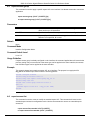
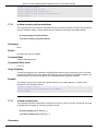
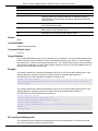
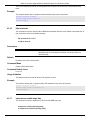
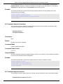
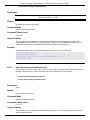
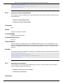
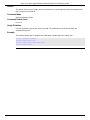
3-12 show dot1x
This command is used to display the IEEE 802.1X global configuration or interface configuration.
show dot1x [interface INTERFACE-ID [, | -]]
Parameters
interface INTERFACE-ID
(Optional) Specifies to display the dot1x configuration on the specified
interface or range of interfaces. If not specified, the global
configuration will be displayed.
,
(Optional) Specifies a series of interfaces, or separate a range of
interfaces from a previous range. No space is allowed before and after
the comma.
-
(Optional) Specifies a range of interfaces. No space is allowed before
and after the hyphen.
Default
None.
Command Mode
EXEC Mode or Any Configuration Mode.
Command Default Level
Level: 1.
Usage Guideline
This command can be used to display the global configuration or interface configuration. If the
configuration command is entered without parameters, the global configuration will be displayed.
Otherwise, the configuration on the specified interface will be displayed.
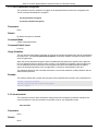
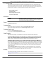
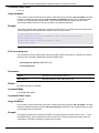
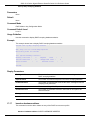
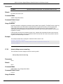
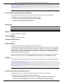
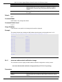
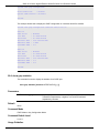
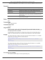
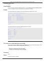
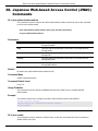
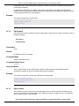
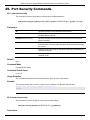
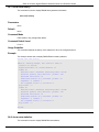
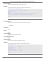
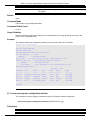
Example
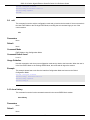
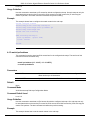
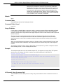
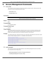
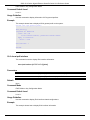
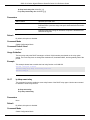
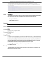
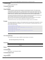
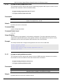
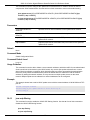
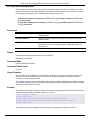
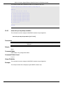
This example shows how to display the dot1X global configuration.
32
DGS-1510 Series Gigabit Ethernet SmartPro Switch CLI Reference Guide
Switch# show dot1x
802.1X
Trap State
: Enabled
: Enabled
Switch#
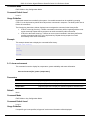
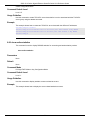
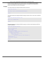
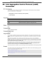
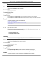
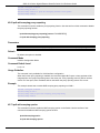
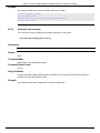
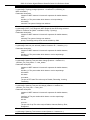
This example shows how to display the dot1X configuration on Ethernet port 1/0/1.
Switch# show dot1x interface eth1/0/1
Interface
PAE
Control Direction
Port Control
Tx Period
Supp Timeout
Server Timeout
Max-req
Forward PDU
:
:
:
:
:
:
:
:
:
eth1/0/1
Authenticator
Both
Auto
30 sec
30 sec
30 sec
2 times
Disabled
Switch#
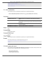
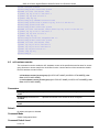
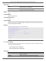
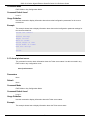
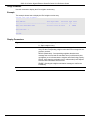
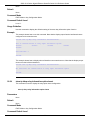
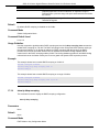
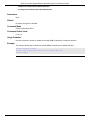
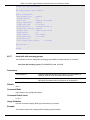
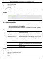
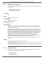
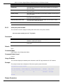
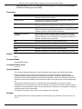
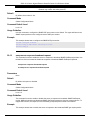
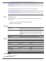
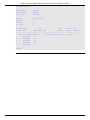
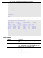
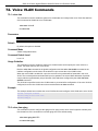
3-13 show dot1x diagnostics
This command is used to display IEEE 802.1X diagnostics. If no interface is specified, information about
all interfaces will be displayed.
show dot1x diagnostics [interface INTERFACE-ID [, | -]]
Parameters
interface INTERFACE-ID
(Optional) Specifies to display the dot1x diagnostics on the specified
interface or range of interfaces. If not specified, information about all
interfaces will be displayed.
,
(Optional) Specifies a series of interfaces, or separate a range of
interfaces from a previous range. No space is allowed before and after
the comma.
-
(Optional) Specifies a range of interfaces. No space is allowed before
and after the hyphen.
Default
None.
Command Mode
EXEC Mode or Any Configuration Mode.
Command Default Level
Level: 1.
Usage Guideline
33
DGS-1510 Series Gigabit Ethernet SmartPro Switch CLI Reference Guide
This command can be used to display 802.1X diagnostics. Using this command without parameters will
display information about all interfaces. Otherwise, the diagnostics on the specified interface will be
displayed.
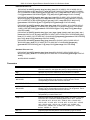
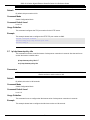
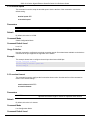
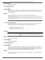
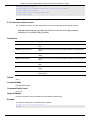
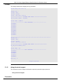
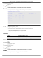
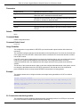
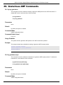
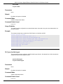
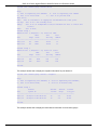
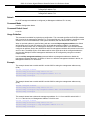
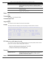
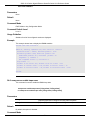
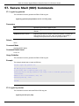
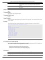
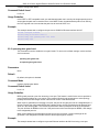
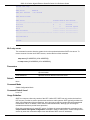
Example
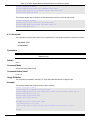
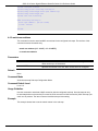
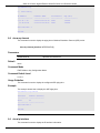
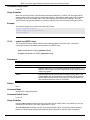
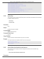
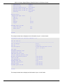
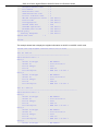
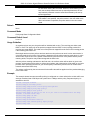
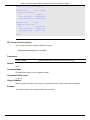
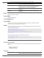
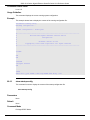
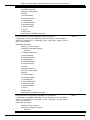
This example shows how to display the dot1X diagnostics on Ethernet port 1/0/1.
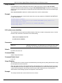
Switch# show dot1x diagnostics interface eth1/0/1
eth1/0/1 dot1x diagnostic information
EntersConnecting
EAP-LogoffsWhileConnecting
EntersAuthenticating
SuccessesWhileAuthenticating
TimeoutsWhileAuthenticating
FailsWhileAuthenticating
ReauthsWhileAuthenticating
EAP-StartsWhileAuthenticating
EAP-LogoffsWhileAuthenticating
ReauthsWhileAuthenticated
EAP-StartsWhileAuthenticated
EAP-LogoffsWhileAuthenticated
BackendResponses
BackendAccessChallenges
BackendOtherRequestsToSupplicant
BackendNonNakResponsesFromSupplicant
BackendAuthSuccesses
BackendAuthFails
are following:
: 20
: 0
: 0
: 0
: 0
: 0
: 0
: 0
: 0
: 0
: 0
: 0
: 0
: 0
: 0
: 0
: 0
: 0
Switch#
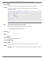
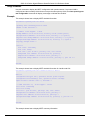
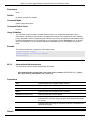
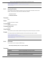
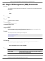
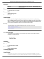
3-14 show dot1x statistics
This command is used to display IEEE 802.1X statistics. If no interface is specified, information about all
interfaces will be displayed.
show dot1x statistics [interface INTERFACE-ID [, | -]]
Parameters
interface INTERFACE-ID
(Optional) Specifies to display the dot1x diagnostics on the specified
interface or range of interfaces. If not specified, information about all
interfaces will be displayed.
,
(Optional) Specifies a series of interfaces, or separate a range of
interfaces from a previous range. No space is allowed before and after
the comma.
-
(Optional) Specifies a range of interfaces. No space is allowed before
and after the hyphen.
Default
None.
34
DGS-1510 Series Gigabit Ethernet SmartPro Switch CLI Reference Guide
Command Mode
EXEC Mode or Any Configuration Mode.
Command Default Level
Level: 1.
Usage Guideline
This command can be used to display 802.1X statistics. Using this command without parameters will
display information about all interfaces. Otherwise, the statistics on the specified interface will be
displayed.
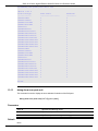
Example
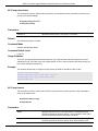
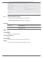
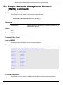
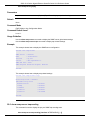
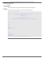
This example shows how to display dot1X statistics on Ethernet port 1/0/1.
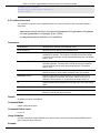
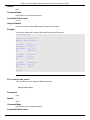
Switch# show dot1x statistics interface eth1/0/1
eth1/0/1 dot1x statistics information:
EAPOL Frames RX
: 1
EAPOL Frames TX
: 4
EAPOL-Start Frames RX
: 0
EAPOL-Req/Id Frames TX
: 6
EAPOL-Logoff Frames RX
: 0
EAPOL-Req Frames TX
: 0
EAPOL-Resp/Id Frames RX
: 0
EAPOL-Resp Frames RX
: 0
Invalid EAPOL Frames RX
: 0
EAP-Length Error Frames RX
: 0
Last EAPOL Frame Version
: 0
Last EAPOL Frame Source
: 00-10-28-00-19-78
Switch#
3-15 show dot1x session-statistics
This command is used to display IEEE 802.1X session statistics. If no interface specified, information
about all interfaces will be displayed.
show dot1x session-statistics [interface INTERFACE-ID [, | -]]
Parameters
interface INTERFACE-ID
(Optional) Specifies to display the dot1x diagnostics on the specified
interface or range of interfaces. If not specified, information about all
interfaces will be displayed.
,
(Optional) Specifies a series of interfaces, or separate a range of
interfaces from a previous range. No space is allowed before and after
the comma.
-
(Optional) Specifies a range of interfaces. No space is allowed before
and after the hyphen.
Default
35
DGS-1510 Series Gigabit Ethernet SmartPro Switch CLI Reference Guide
None.
Command Mode
EXEC Mode or Any Configuration Mode.
Command Default Level
Level: 1.
Usage Guideline
This command can be used to display 802.1X session statistics. Using this command without parameters
will display information about all interfaces. Otherwise, the session statistics on the specified interface will
be displayed.
Example
This example shows how to display dot1X session statistics on Ethernet port 1/0/1.
Switch# show dot1x session-statistics interface eth1/0/1
eth6/0/1 session statistic counters are following:
SessionOctetsRX
: 0
SessionOctetsTX
: 0
SessionFramesRX
: 0
SessionFramesTX
: 0
SessionId
:
SessionAuthenticationMethod
: Remote Authentication Server
SessionTime
: 0
SessionTerminateCause
:SupplicantLogoff
SessionUserName
:
Switch#
3-16 snmp-server enable traps dot1x
This command is used to enable sending SNMP notifications for 802.1X authentication. Use the no form
of the command to disable sending SNMP notifications.
snmp-server enable traps dot1x
no snmp-server enable traps dot1x
Parameters
None.
Default
By default, this option is disabled.
Command Mode
Global Configuration Mode.
Command Default Level
Level: 12.
Usage Guideline
36
DGS-1510 Series Gigabit Ethernet SmartPro Switch CLI Reference Guide
This command can be used to enable or disable sending SNMP notifications for 802.1X authentication.
Example
This example shows how to enable sending trap for 802.1X authentication.
Switch# configure terminal
Switch(config)#snmp-server enable traps dot1x
Switch(config)#
37
DGS-1510 Series Gigabit Ethernet SmartPro Switch CLI Reference Guide
4.
Access Control List (ACL) Commands
4-1 access-list resequence
This command is used to re-sequence the sequence number of the access list entries in an access list.
Use the no form of the command to reset to the default setting.
access-list resequence {NAME | NUMBER} STARTING-SEQUENCE-NUMBER INCREMENT
no access-list resequence
Parameters
NAME
Specifies the name of the access list to be configured. It can be a
maximum of 32 characters.
NUMBER
Specifies the number of the access list to be configured.
STARTING-SEQUENCENUMBER
Specifies that the access list entries will be re-sequenced using this
initial value. The default value is 10. The range of possible sequence
numbers is 1 through 65535.
INCREMENT
Specifies the number that the sequence numbers step. The default
value is 10. For example, if the increment (step) value is 5 and the
beginning sequence number is 20, the subsequent sequence numbers
are 25, 30, 35, 40, and so on. The range of valid values is from 1 to 32.
Default
The default start sequence number is 10.
The default increment is 10.
Command Mode
Global Configuration Mode.
Command Default Level
Level: 12.
Usage Guideline
This feature allows the user to re-sequence the entries of a specified access list with an initial sequence
number determined by the STARTING-SEQUENCE-NUMBER parameter and continuing in the
increments determined by the INCREMENT parameter. If the highest sequence number exceeds the
maximum possible sequence number, then there will be no re-sequencing.
If a rule entry is created without specifying the sequence number, the sequence number will be
automatically assigned. If it is the first entry, a start sequence number is assigned. Subsequent rule
entries are assigned a sequence number that is increment value greater than the largest sequence
number in that access list and the entry is placed at the end of the list.
After the start sequence number or increment change, the sequence number of all previous rules (include
the rules that assigned sequence by user) will change according to the new sequence setting.
Example
This example shows how to re-sequence the sequence number of an IP access-list, named R&D.
38
DGS-1510 Series Gigabit Ethernet SmartPro Switch CLI Reference Guide
Switch# configure terminal
Switch(config)# show access-list ip R&D
Extended IP access list R&D(ID: 3552)
10 permit tcp any 10.20.0.0 255.255.0.0
20 permit tcp any host 10.100.1.2
30 permit icmp any any
Switch(config)# ip extended access-list R&D
Switch(config-ip-ext-acl)# 5 permit tcp any 10.30.0.0 255.255.0.0
Switch(config-ip-ext-acl)# exit
Switch(config)# show access-list ip R&D
Extended IP access list R&D(ID: 3552)5 permit tcp any 10.30.0.0 255.255.0.0
10 permit tcp any 10.20.0.0 255.255.0.0
20 permit tcp any host 10.100.1.2
30 permit icmp any any
Switch(config)# access-list resequence R&D 1 2
Switch(config)# show access-list ip R&D
Extended IP access list R&D(ID: 3552)
1 permit tcp any 10.30.0.0 255.255.0.0
3 permit tcp any 10.20.0.0 255.255.0.0
5 permit tcp any host 10.100.1.2
7 permit icmp any any
Switch(config)#
4-2 acl-hardware-counter
This command is used to enable the ACL hardware counter of the specified access-list name for access
group functions or access map for the VLAN filter function. Use the no form of the command to disable
the ACL hardware counter function.
acl-hardware-counter {access-group {ACCESS-LIST-NAME | ACCESS-LIST-NUMBER} | vlanfilter ACCESS-MAP-NAME}
no acl-hardware-counter {access-group {ACCESS-LIST-NAME | ACCESS-LIST-NUMBER} | vlanfilter ACCESS-MAP-NAME}
Parameters
access-group ACCESS-LISTNAME
Specifies the name of the access list to be configured.
access-group ACCESS-LISTNUMBER
Specifies the number of the access list to be configured.
vlan-filter ACCESS-MAPNAME
Specifies the name of the access map to be configured.
Default
By default, this option is disabled.
Command Mode
Global Configuration Mode.
Command Default Level
Level: 12.
39
DGS-1510 Series Gigabit Ethernet SmartPro Switch CLI Reference Guide
Usage Guideline
The command with parameter access-group will enable the ACL hardware counter for all ports that have
applied the specified access-list name or number. The number of packets, that match each rule, are
counted.
The command with parameter vlan-filter will enable the ACL hardware counter for all VLAN(s) that have
applied the specified VLAN access-map. The number of packets that permitted by each access map are
counted.
Example
This example shows how to enable the ACL hardware counter.
Switch# configure terminal
Switch(config)# acl-hardware-counter access-group abc
Switch(config)#
4-3 action
This command is used to configure the forward, drop, or redirect action of the sub-map in the VLAN
access-map sub-map configuration mode. Use the no command to reset to the default action.
action {forward | drop | redirect INTERFACE-ID}
no action
Parameters
forward
Specifies to forward the packet when matched.
drop
Specifies to drop the packet when matched.
redirect INTERFACE-ID
Specifies the interface ID for the redirection action. Only physical ports
are allowed to be specified.
Default
By default, the action is forward.
Command Mode
VLAN Access-map Sub-map Configuration Mode.
Command Default Level
Level: 12.
Usage Guideline
One sub-map has only one action. The action configured later overwrites the previous action. A VLAN
access map can contain multiple sub-maps. The packet that matches a sub-map (a packet permitted by
the associated access-list) will take the action specified for the sub-map. No further checking against the
next sub-maps is done. If the packet does not match a sub-map, then the next sub-map will be checked.
Example
This example shows how to configure the action in the sub-map.
40
DGS-1510 Series Gigabit Ethernet SmartPro Switch CLI Reference Guide
Switch# show vlan access-map
VLAN access-map vlan-map 20
match mac address: ext_mac(ID: 6856)
action: forward
Switch# configure terminal
Switch(config)# vlan access-map vlan-map 20
Switch(config-access-map)# action redirect eth1/0/5
Switch(config-access-map)# end
Switch# show vlan access-map
VLAN access-map vlan-map 20
match mac address: ext_mac(ID: 6856)
action: redirect eth1/0/5
Switch#
4-4 clear acl-hardware-counter
This command is used to clear the ACL hardware counter.
clear acl-hardware-counter {access-group [ACCESS-LIST-NAME | ACCESS-LIST-NUMBER] |
vlan-filter [ACCESS-MAP-NAME]}
Parameters
access-group ACCESS-LISTNAME
Specifies the name of the access list to be cleared.
access-group ACCESS-LISTNUMBER
Specifies the number of the access list to be configured.
vlan-filter ACCESS-MAPNAME
Specifies the name of the access map to be cleared.
Default
None.
Command Mode
Privileged EXEC Mode.
Command Default Level
Level: 12.
Usage Guideline
If no access-list name or number is specified with the parameter access-group, all access-group
hardware counters will be cleared. If no access-map name is specified with the parameter vlan-filter, all
VLAN filter hardware counters will be cleared.
Example
This example shows how to clear the ACL hardware counter.
Switch(config)# clear acl-hardware-counter access-group abc
Switch#
41
DGS-1510 Series Gigabit Ethernet SmartPro Switch CLI Reference Guide
4-5 expert access-group
This command is used to apply a specific expert ACL to an interface. Use the no command to cancel the
application.
expert access-group {NAME | NUMBER} [in]
no expert access-group [NAME | NUMBER] [in]
Parameters
NAME
Specifies the name of the expert access-list to be configured. The
name can be up to 32 characters.
NUMBER
Specifies the number of the expert access list to be configured.
in
(Optional) Specifies to filter the incoming packets of the interface. If the
direction is not specified, in is used.
Default
None.
Command Mode
Interface Configuration Mode.
Command Default Level
Level: 12.
Usage Guideline
If expert access group is already configured on the interface, the command applied later will overwrite the
previous setting. Only one access-list of the same type can be applied to the same interface; but accesslists of different types can be applied to the same interface.
Example
This example shows how to apply an expert ACL to an interface. The purpose is to apply the ACL
exp_acl on the Ethernet port 1/0/2 to filter the incoming packets.
Switch# configure terminal
Switch(config)# interface eth1/0/2
Switch(config-if)# expert access-group exp_acl in
Switch(config-if)# end
Switch# show access-group interface eth1/0/2
eth1/0/2:
Inbound expert access-list : exp_acl(ID: 8999)
Switch#
4-6 expert access-list
This command is used to create or modify an extended expert ACL. This command will enter into the
extended expert access-list configuration mode. Use the no command to remove an extended expert
access-list.
expert access-list extended NAME [NUMBER]
no expert access-list extended {NAME | NUMBER}
42
DGS-1510 Series Gigabit Ethernet SmartPro Switch CLI Reference Guide
Parameters
NAME
Specifies the name of the extended expert access-list to be configured.
The name can be up to 32 characters.
NUMBER
Specifies the ID number of expert access list. For extended expert
access lists, the value is from 8000 to 9999.
Default
None.
Command Mode
Global Configuration Mode.
Command Default Level
Level: 12.
Usage Guideline
The name must be unique among all access lists. The characters used in the name are case sensitive. If
the access list number is not specified, the biggest unused number in the range of the expert access list
numbers will be assigned automatically.
Example
This example shows how to create an extended expert ACL.
Switch# configure terminal
Switch(config)# expert access-list extended exp_acl
Switch(config-exp-nacl)# end
Switch# show access-list
Access-List-Name
Type
-------------------------------------- --------------exp_acl(ID: 8999)
expert ext-acl
Total Entries: 1
Switch#
4-7 ip access-group
This command is used to specify the IP access list to be applied to an interface. Use the no form of this
command to remove an IP access list.
ip access-group {NAME | NUMBER} [in]
no ip access-group [NAME | NUMBER] [in]
Parameters
NAME
Specifies the name of the IP access list to be applied. The maximum
length is 32 characters.
NUMBER
Specifies the number of the IP access list to be applied.
43
DGS-1510 Series Gigabit Ethernet SmartPro Switch CLI Reference Guide
in
(Optional) Specifies that the IP access list will be applied to check
packets in the ingress direction. If the direction is not specified, in is
used.
Default
None.
Command Mode
Interface Configuration Mode.
Command Default Level
Level: 12.
Usage Guideline
If an IP access group is already configured on the interface, the command applied later will overwrite the
previous setting. Only one access list of the same type can be applied to the same interface; but accesslists of different types can be applied to the same interface.
The association of an access group with an interface will consume the filtering entry resource in the
switch controller. If the resources are insufficient to commit the command, then an error message will be
displayed. There is a limitation on the number of port operator resources. If applying the command
exhausts the available port selectors, then an error message will be displayed.
Example
This example shows how to specify the IP access list “Strict-Control” as an IP access group for an
Ethernet port 6/0/2.
Switch# configure terminal
Switch(config)# interface eth6/0/2
Switch(config-if-gi)#ip access-group Strict-Control
The remaining applicable IP related access entries are 526
Switch(config-if-gi)#
4-8 ip access-list
This command is used to create or modify an IP access list. This command will enter into the IP access
list configuration mode. Use the no command to remove an IP access list.
ip access-list [extended] NAME [NUMBER]
no ip access-list [extended] {NAME | NUMBER}
Parameters
extended
(Optional) Specifies that without this option the IP access list is a
standard IP access list. When using the extended option, more fields
can be chosen for the filter.
NAME
Specifies the name of the IP access list to be configured. The
maximum length is 32 characters. The first character must be a letter.
NUMBER
Specifies the ID number of the IP access list. For standard IP access
lists, this value is from 1 to 1999. For extended IP access lists, this
value is from 2000 to 3999.
Default
44
DGS-1510 Series Gigabit Ethernet SmartPro Switch CLI Reference Guide
None.
Command Mode
Global Configuration Mode.
Command Default Level
Level: 12.
Usage Guideline
The name must be unique among all access lists. The characters used in the name are case sensitive. If
the access list number is not specified, the biggest unused number in the range of IP access list numbers
will be assigned automatically.
Example
This example shows how to configure an extended IP access list, named “Strict-Control” and an IP
access-list, named “pim-srcfilter”.
Switch# configure terminal
Switch(config)# ip access-list extended Strict-Control
Swtich(config-ip-ext-acl)# permit tcp any 10.20.0.0 255.255.0.0
Swtich(config-ip-ext-acl)# exit
Swtich(config)# ip access-list pim-srcfilter
Switch(config-ip-acl)# permit host 172.16.65.193 any
Switch(config-ip-acl)#
4-9 ipv6 access-group
This command is used to specify the IPv6 access list to be applied to an interface. Use the no command
to remove an IPv6 access list.
ipv6 access-group {NAME | NUMBER} [in]
no ipv6 access-group [NAME | NUMBER] [in]
Parameters
NAME
Specifies the name of the IPv6 access list to be applied.
NUMBER
Specifies the number of the IPv6 access list to be applied.
in
(Optional) Specifies that the IPv6 access list will be applied to check in
the ingress direction. If the direction is not specified, in is used.
Default
None.
Command Mode
Interface Configuration Mode.
Command Default Level
Level: 12.
Usage Guideline
Only one access list of the same type can be applied to the same interface; but access lists of different
types can be applied to the same interface. The association of an access group with an interface will
45
DGS-1510 Series Gigabit Ethernet SmartPro Switch CLI Reference Guide
consume the filtering entry resource in the switch controller. If the resource is insufficient to commit the
command, then an error message will be displayed.
There is a limitation on the number of port operator resources. If applying the command exhausts the
available port selectors, then an error message will be displayed.
Example
This example shows how to specify the IPv6 access list “ip6-control” as an IP access group for eth3/0/3.
Switch# configure terminal
Switch(config)# interface eth3/0/3
Switch(config-if)# ipv6 access-group ip6-control in
The remaining applicable IPv6 related access entries are 156
Switch(config-if)#
4-10 ipv6 access-list
This command is used to create or modify an IPv6 access list. This command will enter into IPv6 accesslist configuration mode. Use the no form of this command to remove an IPv6 access list.
ipv6 access-list [extended] NAME [NUMBER]
no ipv6 access-list [extended] {NAME | NUMBER}
Parameters
extended
(Optional) Specifies that without this option the IPv6 access list is a
standard IPv6 access list. When using the extended option, the IPv6
access list is an extended IPv6 access list and more fields can be
chosen for the filter.
NAME
Specifies the name of the IPv6 access list to be configured. The
maximum length is 32 characters.
NUMBER
Specifies the ID number of the IPv6 access list. For standard IPv6
access lists, this value is from 11000 to 12999. For extended IPv6
access lists, this value is from 13000 to 14999.
Default
None.
Command Mode
Global Configuration Mode.
Command Default Level
Level: 12.
Usage Guideline
The name must be unique among all access lists. The characters used in the name are case sensitive. If
the access list number is not specified, the biggest unused number in the range of the IPv6 access list
numbers will be assigned automatically.
Example
This example shows how to configure an IPv6 extended access list, named ip6-control.
46
DGS-1510 Series Gigabit Ethernet SmartPro Switch CLI Reference Guide
Switch# configure terminal
Switch(config)# ipv6 access-list extended ip6-control
Swtich(config-ipv6-ext-acl)# permit tcp any 2002:f03::1/16
Switch(config-ipv6-ext-acl)#
This example shows how to configure an IPv6 standard access list, named ip6-std-control.
Switch# configure terminal
Switch(config)# ipv6 access-list ip6-std-control
Swtich(config-ipv6-acl)# permit any fe80::101:1/54
Switch(config-ipv6-acl)#
4-11 list-remark
This command is used to add remarks for the specified ACL. Use the no command to delete the remarks.
list-remark TEXT
no list-remark
Parameters
TEXT
Specifies the remark information. The information can be up to 256
characters long.
Default
None.
Command Mode
Access-list Configuration Mode.
Command Default Level
Level: 12.
Usage Guideline
This command is available in the MAC, IP, IPv6, and Expert Access-list Configure mode.
Example
This example shows how to add a remark to the access-list.
Switch# configure terminal
Switch(config)# ip extended access-list R&D
Switch(config-ip-ext-acl)# list-remark This access-list is used to match any IP
packets from the host 10.2.2.1.
Switch(config-ip-ext-acl)# end
Switch# show access-list ip
Extended IP access list R&D(ID: 3999)
10 permit host 10.2.2.1 any
This access-list is used to match any IP packets from the host 10.2.2.1.
Switch#
47
DGS-1510 Series Gigabit Ethernet SmartPro Switch CLI Reference Guide
4-12 mac access-group
This command is used to specify a MAC access list to be applied to an interface. Use the no command to
remove the access group control from the interface.
mac access-group {NAME | NUMBER} [in]
no mac access-group [NAME | NUMBER] [in]
Parameters
NAME
Specifies the name of the MAC access list to be applied.
NUMBER
Specifies the number of the MAC access list to be applied.
in
(Optional) Specifies that the MAC access list will be applied to check in
the ingress direction. If direction is not specified, in is used.
Default
None.
Command Mode
Interface Configuration Mode.
Command Default Level
Level: 12.
Usage Guideline
If MAC access group is already configured on the interface, the command applied later will overwrite the
previous setting. MAC access-groups will only check non-IP packets.
Only one access list of the same type can be applied to the same interface; but access lists of different
types can be applied to the same interface.
The association of an access group with an interface will consume the filtering entry resource in the
switch controller. If the resource is insufficient to commit the command, then an error message will be
displayed.
Example
This example shows how to apply the MAC access list daily-profile to Ethernet port 5/0/1.
Switch# configure terminal
Switch(config)# interface eth5/0/1
Switch(config-if-gi)# mac access-group daily-profile in
The remaining applicable MAC access entries are 204
Switch(config-if-gi)#
4-13 mac access-list
This command is used to create or modify an MAC access list and this command will enter the MAC
access list configuration mode. Use the no command to delete a MAC access list.
mac access-list extended NAME [NUMBER]
no mac acces-list extended {NAME | NUMBER}
48
DGS-1510 Series Gigabit Ethernet SmartPro Switch CLI Reference Guide
Parameters
NAME
Specifies the name of the MAC access-list to be configured. The
maximum length is 32 characters.
NUMBER
Specifies the ID number of the MAC access list, For extended MAC
access lists, this value is from 6000 to 7999.
Default
None.
Command Mode
Global Configuration Mode.
Command Default Level
Level: 12.
Usage Guideline
Use this command to enter the MAC access-list configuration mode and use the permit or deny command
to specify the entries. The name must be unique among all access lists. The characters of the name are
case sensitive. If the access list number is not specified, the biggest unused number in the range of the
MAC access list numbers will be assigned automatically.
Example
This example shows how to enter the MAC access list configuration mode for a MAC access list named
“daily profile”.
Switch# configure terminal
Switch(config)# mac access-list extended daily-profile
Switch(config-mac-ext-acl)#
4-14 match ip address
This command is used to associate an IP access list for the configured sub-map. The no form of this
command removes the match entry.
match ip address {ACL-NAME | ACL-NUMBER}
no match ip address
Parameters
ACL-NAME
Specifies the name of the ACL access list to be configured. The name
can be up to 32 characters.
ACL-NUMBER
Specifies the number of the IP ACL access list to be configured.
Default
None.
Command Mode
VLAN Access-map Sub-map Configuration Mode.
Command Default Level
49
DGS-1510 Series Gigabit Ethernet SmartPro Switch CLI Reference Guide
Level: 12.
Usage Guideline
Use this command to associate an IP access list with the configured sub-map. One sub-map can only be
associated with one access list (IP access list, IPv6 access list or MAC access list). IP sub-map just
checks IP packets. The newer command overwrites the previous setting.
Example
This example shows how to configure the match content in the sub-map.
Switch# configure terminal
Switch(config)# vlan access-map vlan-map 20
Switch(config-access-map)# match ip address sp1
Switch(config-access-map)# end
Switch# show vlan access-map
VLAN access-map vlan-map 20
match ip address: sp1(ID: 1999)
action: forward
Switch#
4-15 match ipv6 address
This command is used to associate IPv6 access lists for the configured sub-maps. The no form of this
command removes the match entry.
match ipv6 address {ACL-NAME | ACL-NUMBER}
no match ipv6 address
Parameters
ACL-NAME
Specifies the name of the IPv6 ACL access list to be configured. The
name can be up to 32 characters.
ACL-NUMBER
Specifies the number of the IPv6 ACL access list to be configured.
Default
None.
Command Mode
VLAN Access-map Sub-map Configuration Mode.
Command Default Level
Level: 12.
Usage Guideline
Use this command to associate an IPv6 access list with the configured sub-map. One sub-map can only
be associated with one access list (IP access list, IPv6 access list or MAC access list). IPv6 sub-map just
checks IPv6 packets. The later command overwrites the previous setting.
Example
This example shows how to set the match content in the sub-map.
50
DGS-1510 Series Gigabit Ethernet SmartPro Switch CLI Reference Guide
Switch# configure terminal
Switch(config)# vlan access-map vlan-map 20
Switch(config-access-map)# match ipv6 address sp1
Switch(config-access-map)# end
Switch# show vlan access-map
VLAN access-map vlan-map 20
match ipv6 address: sp1(ID: 12999)
action: forward
Switch#
4-16 match mac address
This command is used to associate MAC access lists for the configured sub-maps. The no form of this
command removes the match entry.
match mac address {ACL-NAME | ACL-NUMBER}
no match mac address
Parameters
ACL-NAME
Specifies the name of the ACL MAC access list to be configured. The
name can be up to 32 characters.
ACL-NUMBER
Specifies the number of the ACL MAC access list to be configured.
Default
None.
Command Mode
VLAN Access-map Sub-map Configuration Mode.
Command Default Level
Level: 12.
Usage Guideline
Use this command to associate a MAC access list with the configured sub-map. One sub-map can only
be associated with one access list (IP access list, IPv6 access list or MAC access list). MAC sub-map just
check non-IP packets. The later command overwrites the previous setting.
Example
This example shows how to set the match content in the sub-map.
51
DGS-1510 Series Gigabit Ethernet SmartPro Switch CLI Reference Guide
Switch# configure terminal
Switch(config)# vlan access-map vlan-map 30
Switch(config-access-map)# match mac address ext_mac
Switch(config-access-map)# end
Switch# show vlan access-map
VLAN access-map vlan-map 20
match ip address: sp1(ID: 3999)
action: forward
VLAN access-map vlan-map 30
match mac address: ext_mac(ID: 7999)
action: forward
Switch#
4-17 permit | deny (expert access-list)
This command is used to add a permit or deny entry. Use the no command to remove an entry.
Extended Expert ACL:
[SEQUENCE-NUMBER] {permit | deny} PROTOCOL {SRC-IP-ADDR SRC-IP-WILDCARD | host
SRC-IP-ADDR | any} {SRC-MAC-ADDR SRC-MAC-WILDCARD | host SRC-MAC-ADDR | any}
{DST-IP-ADDR DST-IP-WILDCARD | host DST-IP-ADDR | any} {DST-MAC-ADDR DST-MACWILDCARD | host DST-MAC-ADDR | any} [cos OTER-COS] [vlan OUTER-VLAN] [fragments]
[[precedence PRECEDENCE] [tos TOS] | dscp DSCP] [time-range PROFILE-NAME]
[SEQUENCE-NUMBER] {permit | deny} tcp {SRC-IP-ADDR SRC-IP-WILDCARD | host SRC-IPADDR | any} {SRC-MAC-ADDR SRC-MAC-WILDCARD | host SRC-MAC-ADDR | any} [{eq | lt | gt |
neq} PORT | range MIN-PORT MAX-PORT] {DST-IP-ADDR DST-IP-WILDCARD | host DST-IPADDR | any} {DST-MAC-ADDR DST-MAC-WILDCARD | host DST-MAC-ADDR | any} [{eq | lt | gt |
neq} PORT | range MIN-PORT MAX-PORT] [TCP-FLAG] [cos OUTER-COS] [vlan OUTER-VLAN]
[[precedence PRECEDENCE] [tos TOS] | dscp DSCP] [time-range PROFILE-NAME]
[SEQUENCE-NUMBER] {permit | deny} udp {SRC-IP-ADDR SRC-IP-WILDCARD | host SRC-IPADDR | any} {SRC-MAC-ADDR SRC-MAC-WILDCARD | host SRC-MAC-ADDR | any} [{eq | lt | gt |
neq} PORT | range MIN-PORT MAX-PORT] {DST-IP-ADDR DST-IP-WILDCARD | host DST-IPADDR | any} {DST-MAC-ADDR DST-MAC-WILDCARD | host DST-MAC-ADDR | any} [{eq | lt | gt |
neq} PORT | range MIN-PORT MAX-PORT] [cos OUTER-COS] [vlan OUTER-VLAN] [[precedence
PRECEDENCE] [tos TOS] | dscp DSCP] [time-range PROFILE-NAME]
[SEQUENCE-NUMBER] {permit | deny} icmp {SRC-IP-ADDR SRC-IP-WILDCARD | host SRC-IPADDR | any} {SRC-MAC-ADDR SRC-MAC-WILDCARD | host SRC-MAC-ADDR | any} {DST-IPADDR DST-IP-WILDCARD | host DST-IP-ADDR | any} {DST-MAC-ADDR DST-MAC-WILDCARD |
host DST-MAC-ADDR | any} [ICMP-TYPE [ICMP-CODE] | ICMP-MESSAGE] [cos OUTER-COS]
[vlan OUTER-VLAN] [[precedence PRECEDENCE] [tos TOS] | dscp DSCP] [time-range
PROFILE-NAME]
no SEQUENCE-NUMBER
Parameters
SEQUENCE-NUMBER
Specifies the sequence number. The range is from 1 to 65535. The
lower the number is, the higher the priority of the permit/deny rule.
cos OUTER-COS
(Optional) Specifies the outer priority value. This value must be
between 0 and 7.
52
DGS-1510 Series Gigabit Ethernet SmartPro Switch CLI Reference Guide
vlan OUTER-VLAN
(Optional) Specifies the outer VLAN ID.
any
Specifies to use any source MAC address, any destination MAC
address, any source IP address, or any destination IP address.
host SRC-MAC-ADDR
Specifies a specific source host MAC address.
SRC-MAC-ADDR SRC-MACWILDCARD
Specifies a group of source MAC addresses by using a wildcard
bitmap. The bit corresponding to the bit value 1 will be ignored. The bit
corresponding to bit value 0 will be checked.
host DST-MAC-ADDR
Specifies a specific destination host MAC address.
DST-MAC-ADDR DST-MACWILDCARD
Specifies a group of destination MAC addresses by using a wildcard
bitmap. The bit corresponding to the bit value 1 will be ignored. The bit
corresponding to the bit value 0 will be checked.
PROTOCOL
(Optional) Specifies the IP protocol ID. Enter the following keywords:
eigrp, esp, gre, igmp, ospf, pim, vrrp, pcp, and ipinip.
host SRC-IP-ADDR
Specifies a specific source host IP address.
SRC-IP-ADDR SRC-IPWILDCARD
Specifies a group of source IP addresses by using a wildcard bitmap.
The bit corresponding to the bit value 1 will be ignored. The bit
corresponding to the bit value 0 will be checked.
host DST-IP-ADDR
Specifies a specific destination host IP address.
DST-IP-ADDR DST-IPWILDCARD
Specifies a group of destination IP addresses by using a wildcard
bitmap. The bit corresponding to the bit value 1 will be ignored. The bit
corresponding to the bit value 0 will be checked.
precedence PRECEDENCE
(Optional) Specifies that packets can be filtered by precedence level,
as specified by a number from 0 to 7.
tos TOS
(Optional) Specifies that packets can be filtered by type of service
level, as specified by a number from 0 to 15.
dscp DSCP
(Optional) Specifies the matching DSCP code in IP header. The range
is from 0 to 63, or select the following DSCP name: af11 - 001010,
af12 -001100, af13 - 001110, af21 - 010010, af22 - 010100, af23 010110, af31 - 011010, af32 - 011100, af33 - 011110, af41 - 100010,
af42 - 100100, af43 - 100110, cs1 - 001000, cs2 - 010000, cs3 011000, cs4 - 100000, cs5 - 101000, cs6 - 110000, cs7 - 111000,
default - 000000, ef – 101110.
lt PORT
(Optional) Specifies to match if less than the specified port number.
gt PORT
(Optional) Specifies to match if greater than the specified port number.
eq PORT
(Optional) Specifies to match if equal to the specified port number.
neq PORT
(Optional) Specifies to match if not equal to the specified port number.
range MIN-PORT MAX-PORT
(Optional) Specifies to match if fall within the range of ports.
TCP-FLAG
(Optional) Specifies the TCP flag fields and the specified TCP header
bits called ack (acknowledge), fin (finish), psh (push), rst (reset), syn
(synchronize), or urg (urgent).
fragments
(Optional) Specifiese the packet fragment’s filtering.
time-range PROFILE-NAME
(Optional) Specifies the name of time period profile associated with the
access list delineating its activation period.
ICMP-TYPE
(Optional) Specifies the ICMP message type. The valid number for the
message type is from 0 to 255.
ICMP-CODE
(Optional) Specifies the ICMP message code. The valid number for the
message code is from 0 to 255.
53
DGS-1510 Series Gigabit Ethernet SmartPro Switch CLI Reference Guide
ICMP-MESSAGE
(Optional) Specifies the ICMP message. The following pre-defined
parameters are available for selection: beyond-scope, destinationunreachable, echo-reply, echo-request, header, hop-limit, mld-query,
mld-reduction, mld-report, nd-na, nd-ns, next-header, no-admin, noroute, packet-too-big, parameter-option, parameter-problem, portunreachable, reassembly-timeout, redirect, renum-command, renumresult, renum-seq-number, router-advertisement, router-renumbering,
router-solicitation, time-exceeded, unreachable.
Default
None.
Command Mode
Extended Expert Access-list Configuration Mode.
Command Default Level
Level: 12.
Usage Guideline
If a rule entry is created without a sequence number, a sequence number will be automatically assigned.
If it is the first entry, the sequence number 10 is assigned. A subsequent rule entry will be assigned a
sequence number that is 10 greater than the largest sequence number in that access list and is placed at
the end of the list.
The user can use the command access-list sequence to change the start sequence number and
increment number for the specified access list. After the command is applied, the new rule without
specified sequence number will be assigned sequence based new sequence setting of the specified
access list.
When you manually assign the sequence number, it is better to have a reserved interval for future lower
sequence number entries. Otherwise, it will create extra effort to insert an entry with a lower sequence
number.
The sequence number must be unique in the domain of an access-list. If you enter a sequence number
that is already present, an error message will be shown.
Example
This example shows how to use the extended expert ACL. The purpose is to deny all the TCP packets
with the source IP address 192.168.4.12 and the source MAC address 00:13:00:49:82:72.
Switch# configure terminal
Switch(config)# expert access-list extended exp_acl
Switch(config-exp-nacl)# deny tcp host 192.168.4.12 host 0013.0049.8272 any any
Switch(config-exp-nacl)# end
Switch# show access-lists
Extended Expert access list exp_acl(ID: 9999)
10 deny tcp host 192.168.4.12 host 0013.0049.8272 any any
Switch#
4-18 permit | deny (ip access-list)
This command is used to add a permit or a deny entry. Use the no form of the command to remove an
entry.
54
DGS-1510 Series Gigabit Ethernet SmartPro Switch CLI Reference Guide
Extended Access List:
[SEQUENCE-NUMBER] {permit | deny} tcp {any | host SRC-IP-ADDR | SRC-IP-ADDR SRC-IPWILDCARD} [{eq | lt | gt | neq} PORT | range MIN-PORT MAX-PORT] {any | host DST-IP-ADDR |
DST-IP-ADDR DST-IP-WILDCARD} [{eq | lt | gt | neq} PORT | range MIN-PORT MAX-PORT] [TCPFLAG] [[precedence PRECEDENCE] [tos TOS] | dscp DSCP] [time-range PROFILE-NAME]
[SEQUENCE-NUMBER] {permit | deny} udp {any | host SRC-IP-ADDR | SRC-IP-ADDR SRC-IPWILDCARD} [{eq | lt | gt | neq} PORT | range MIN-PORT MAX-PORT] {any | host DST-IP-ADDR |
DST-IP-ADDR DST-IP-WILDCARD} [{eq | lt | gt | neq} PORT | range MIN-PORT MAX-PORT]
[[precedence PRECEDENCE] [tos TOS] | dscp DSCP] [time-range PROFILE-NAME]
[SEQUENCE-NUMBER] {permit | deny} icmp {any | host SRC-IP-ADDR | SRC-IP-ADDR SRC-IPWILDCARD} {any | host DST-IP-ADDR | DST-IP-ADDR DST-IP-WILDCARD} [ICMP-TYPE [ICMPCODE] | ICMP-MESSAGE] [[precedence PRECEDENCE] [tos TOS] | dscp DSCP] [time-range
PROFILE-NAME]
[SEQUENCE-NUMBER] {permit | deny} {gre | esp | eigrp | igmp | ipinip | ospf | pcp | pim | vrrp |
protocol-id PROTOCOL-ID} {any | host SRC-IP-ADDR | SRC-IP-ADDR SRC-IP-WILDCARD} {any |
host DST-IP-ADDR | DST-IP-ADDR DST-IP-WILDCARD} [fragments] [[precedence PRECEDENCE]
[tos TOS] | dscp DSCP] [time-range PROFILE-NAME]
[SEQUENCE-NUMBER] {permit | deny} {any | host SRC-IP-ADDR | SRC-IP-ADDR SRC-IPWILDCARD} [any | host DST-IP-ADDR | DST-IP-ADDR DST-IP-WILDCARD] [fragments]
[[precedence PRECEDENCE] [tos TOS] | dscp DSCP] [time-range PROFILE-NAME]
Standard IP Access List:
[SEQUENCE-NUMBER] {permit | deny} {any | host SRC-IP-ADDR | SRC-IP-ADDR SRC-IPWILDCARD} [any | host DST-IP-ADDR | DST-IP-ADDR DST-IP-WILDCARD] [time-range PROFILENAME]
no SEQUENCE-NUMBER
Parameters
SEQUENCE-NUMBER
Specifies the sequence number. The range is from 1 to 65535. The
lower the number is, the higher the priority of the permit/deny rule.
any
Specifies any source IP address or any destination IP address.
host SRC-IP-ADDR
Specifies a specific source host IP address.
SRC-IP-ADDR SRC-IPWILDCARD
Specifies a group of source IP addresses by using a wildcard bitmap.
The bit corresponding to the bit value 1 will be ignored. The bit
corresponding to the bit value 0 will be checked.
host DST-IP-ADDR
Specifies a specific destination host IP address.
DST-IP-ADDR DST-IPWILDCARD
Specifies a group of destination IP addresses by using a wildcard
bitmap. The bit corresponding to the bit value 1 will be ignored. The bit
corresponding to the bit value 0 will be checked.
precedence PRECEDENCE
(Optional) Specifies that packets can be filtered by precedence level,
as specified by a number from 0 to 7.
dscp DSCP
(Optional) Specifies the matching DSCP code in IP header. The range
is from 0 to 63, or select the following DSCP name: af11 - 001010,
af12 -001100, af13 - 001110, af21 - 010010, af22 - 010100, af23 010110, af31 - 011010, af32 - 011100, af33 - 011110, af41 - 100010,
af42 - 100100, af43 - 100110, cs1 - 001000, cs2 - 010000, cs3 011000, cs4 - 100000, cs5 - 101000, cs6 - 110000, cs7 - 111000,
default - 000000, ef – 101110.
tos TOS
(Optional) Specifies that packets can be filtered by type of service
55
DGS-1510 Series Gigabit Ethernet SmartPro Switch CLI Reference Guide
level, as specified by a number from 0 to 15.
lt PORT
(Optional) Specifies to match if less than the specified port number.
gt PORT
(Optional) Specifies to match if greater than the specified port number.
eq PORT
(Optional) Specifies to match if equal to the specified port number.
neq PORT
(Optional) Specifies to match if not equal to the specified port number.
range MIN-PORT MAX-PORT
(Optional) Specifies to match if fall within the range of ports.
TCP-FLAG
(Optional) Specifies the TCP flag fields and the specified TCP header
bits called ack (acknowledge), fin (finish), psh (push), rst (reset), syn
(synchronize), or urg (urgent).
fragments
(Optional) Specifiese the packet fragment’s filtering.
time-range PROFILE-NAME
(Optional) Specifies the name of the time period profile associated with
the access list delineating its activation period.
tcp, udp, igmp, ipinip, gre,
esp, eigrp, ospf, pcp, pim,
vrrp
Specifies Layer 4 protocols.
PROTOCOL-ID
(Optional) Specifies the protocol ID. The valid value is from 0 to 255.
ICMP-TYPE
(Optional) Specifies the ICMP message type. The valid number for the
message type is from 0 to 255.
ICMP-CODE
(Optional) Specifies the ICMP message code. The valid number for the
message code is from 0 to 255.
ICMP-MESSAGE
(Optional) Specifies the ICMP message. The pre-defined parameters
are available for selection: administratively-prohibited,alternateaddress,conversion-error,host-prohibited,net-prohibited,echo,echoreply,pointer-indicates-error,host-isolated,host-precedenceviolation,host-redirect,host-tos-redirect,host-tos-unreachable,hostunknown,host-unreachable, information-reply,informationrequest,mask-reply,mask-request,mobile-redirect,net-redirect,net-tosredirect,net-tos-unreachable, net-unreachable,net-unknown,badlength,option-missing,packet-fragment,parameter-problem,portunreachable,precedence-cutoff, protocol-unreachable,reassemblytimeout,redirect-message,router-advertisement,routersolicitation,source-quench,source-route-failed, timeexceeded,timestamp-reply,timestamp-request,traceroute,ttlexpired,unreachable.
Default
None.
Command Mode
IP Access-list Configuration Mode.
Command Default Level
Level: 12.
Usage Guideline
If a rule entry is created without a sequence number, a sequence number will be automatically assigned.
If it is the first entry, the sequence number 10 is assigned. A subsequent rule entry will be assigned a
sequence number that is 10 greater than the largest sequence number in that access list and is placed at
the end of the list.
The user can use the command access-list sequence to change the start sequence number and
increment number for the specified access list. After the command is applied, the new rule without
56
DGS-1510 Series Gigabit Ethernet SmartPro Switch CLI Reference Guide
specified sequence number will be assigned sequence based new sequence setting of the specified
access list.
When you manually assign the sequence number, it is better to have a reserved interval for future lower
sequence number entries. Otherwise, it will create extra effort to insert an entry with a lower sequence
number.
The sequence number must be unique in the domain of an access-list. If you enter a sequence number
that is already present, an error message will be shown.
To create a matching rule for an IP standard access list, only the source IP address or destination IP
address fields can be specified.
Example
This example shows how to create four entries for an IP extended access list, named Strict-Control.
These entries are: permit TCP packets destined to network 10.20.0.0, permit TCP packets destined to
host 10.100.1.2, permit all TCP packets go to TCP destination port 80 and permit all ICMP packets.
Switch# configure terminal
Switch(config)# ip extended access-list Strict-Control
Switch(config-ip-ext-acl)# permit tcp any 10.20.0.0 0.0.255.255
Switch(config-ip-ext-acl)# permit tcp any host 10.100.1.2
Switch(config-ip-ext-acl)# permit tcp any any eq 80
Switch(config-ip-ext-acl)# permit icmp any any
Switch(config-ip-ext-acl)#
This example shows how to create two entries for an IP standard access-list, named “std-ip”. These
entries are: permit IP packets destined to network 10.20.0.0, permit IP packets destined to host
10.100.1.2.
Switch# configure terminal
Switch(config)# ip access-list std-acl
Switch(config-ip-acl)# permit any 10.20.0.0 0.0.255.255
Switch(config-ip- acl)# permit any host 10.100.1.2
Switch(config-ip- acl)#
4-19 permit | deny (ipv6 access-list)
This command is used to add a permit entry or deny entry to the IPv6 access list. Use the no form of this
command to remove an entry from the IPv6 access list.
Extended IPv6 Access List:
[SEQUENCE-NUMBER] {permit | deny} tcp {any | host SRC-IPV6-ADDR | SRC-IPV6ADDR/PREFIX-LENGTH} [{eq | lt | gt | neq} PORT | range MIN-PORT MAX-PORT] {any | host
DST-IPV6-ADDR | DST-IPV6-ADDR/PREFIX-LENGTH} [{eq | lt | gt | neq} PORT | range MIN-PORT
MAX-PORT] [TCP-FLAG] [dscp VALUE] [flow-label FLOW-LABEL] [time-range PROFILE-NAME]
[SEQUENCE-NUMBER] {permit | deny} udp {any | host SRC-IPV6-ADDR | SRC-IPV6ADDR/PREFIX-LENGTH} [{eq | lt | gt | neq} PORT | range MIN-PORT MAX-PORT] {any | host
DST-IPV6-ADDR | DST-IPV6-ADDR/PREFIX-LENGTH} [{eq | lt | gt | neq} PORT | range MIN-PORT
MAX-PORT] [dscp VALUE] [flow-label FLOW-LABEL] [time-range PROFILE-NAME]
[SEQUENCE-NUMBER] {permit | deny} icmp {any | host SRC-IPV6-ADDR | SRC-IPV6ADDR/PREFIX-LENGTH} {any | host DST-IPV6-ADDR | DST-IPV6-ADDR/PREFIX-LENGTH}
[ICMP-TYPE [ICMP-CODE] | ICMP-MESSAGE] [dscp VALUE] [flow-label FLOW-LABEL] [timerange PROFILE-NAME]
57
DGS-1510 Series Gigabit Ethernet SmartPro Switch CLI Reference Guide
[SEQUENCE-NUMBER] {permit | deny} {esp | pcp | sctp | protocol-id PROTOCOL-ID} {any | host
SRC-IPV6-ADDR | SRC-IPV6-ADDR/PREFIX-LENGTH} {any | host DST-IPV6-ADDR | DST-IPV6ADDR/PREFIX-LENGTH} [fragments] [dscp VALUE] [flow-label FLOW-LABEL] [time-range
PROFILE-NAME]
[SEQUENCE-NUMBER] {permit | deny} {any | host SRC-IPV6-ADDR | SRC-IPV6-ADDR/PREFIXLENGTH} [any | host DST-IPV6-ADDR | DST-IPV6-ADDR/PREFIX-LENGTH] [fragments] [dscp
VALUE] [flow-label FLOW-LABEL] [time-range PROFILE-NAME]
Standard IPv6 Access List:
[SEQUENCE-NUMBER] {permit | deny} {any | host SRC-IPV6-ADDR | SRC-IPV6-ADDR/PREFIXLENGTH} [any | host DST-IPV6-ADDR | DST-IPV6-ADDR/PREFIX-LENGTH] [time-range
PROFILE-NAME]
no SEQUENCE-NUMBER
Parameters
SEQUENCE-NUMBER
Specifies the sequence number. The range is from 1 to 65535. The
lower the number is, the higher the priority of the permit/deny rule.
any
Specifies any source IPv6 address or any destination IPv6 address.
host SRC-IPV6-ADDR
Specifies a specific source host IPv6 address.
SRC-IPV6-ADDR/PREFIXLENGTH
Specifies a source IPv6 network.
host DST-IPV6-ADDR
Specifies a specific destination host IPv6 address.
DST-IPV6-ADDR/PREFIXLENGTH
Specifies a destination IPv6 network.
tcp, udp, icmp, esp, pcp ,sctp
Specifies the Layer 4 protocol type.
dscp VALUE
(Optional) Specifies the matching traffic class value in IPv6 header.
The range is from 0 to 63, or select the following DSCP name: af11 001010, af12 -001100, af13 - 001110, af21 - 010010, af22 - 010100,
af23 - 010110, af31 - 011010, af32 - 011100, af33 - 011110, af41 100010, af42 - 100100, af43 - 100110, cs1 - 001000, cs2 - 010000,
cs3 - 011000, cs4 - 100000, cs5 - 101000, cs6 - 110000, cs7 - 111000,
default - 000000, ef – 101110.
lt PORT
(Optional) Specifies to match if less than the specified port number.
gt PORT
(Optional) Specifies to match if greater than the specified port number.
eq PORT
(Optional) Specifies to match if equal to the specified port number.
neq PORT
(Optional) Specifies to match if not equal to the specified port number.
range MIN-PORT MAX-PORT
(Optional) Specifies to match if fall within the range of ports.
PROTOCOL-ID
(Optional) Specifies the protocol ID. The valid value is from 0 to 255.
ICMP-TYPE
(Optional) Specifies the ICMP message type. The valid number of the
message type is from 0 to 255.
ICMP-CODE
(Optional)Specifies the ICMP message code. The valid number of the
code type is from 0 to 255.
ICMP-MESSAGE
(Optional) Specifies the ICMP message. The following pre-defined
parameters are available for selection: beyond-scope, destinationunreachable, echo-reply, echo-request, erroneous_header, hop-limit,
multicast-listener-query, multicast-listener-done, multicast-listenerreport, nd-na, nd-ns, next-header, no-admin, no-route, packet-too-big,
58
DGS-1510 Series Gigabit Ethernet SmartPro Switch CLI Reference Guide
parameter-option, parameter-problem, port-unreachable, reassemblytimeout, redirect, renum-command, renum-result, renum-seq-number,
router-advertisement, router-renumbering, router-solicitation, timeexceeded, unreachable.
TCP-FLAG
(Optional) Specifies the TCP flag fields and the specified TCP header
bits called ack (acknowledge), fin (finish), psh (push), rst (reset), syn
(synchronize), or urg (urgent).
flow-label FLOW-LABEL
(Optional) Specifies the flow label value, within the range of 0 to
1048575.
fragments
(Optional) Specifiese the packet fragment’s filtering.
time-range PROFILE-NAME
(Optional) Specifies the name of time period profile associated with the
access list delineating its activation period.
Default
None.
Command Mode
IPv6 Access-list Configuration Mode.
Command Default Level
Level: 12.
Usage Guideline
If a rule entry is created without a sequence number, a sequence number will be automatically assigned.
If it is the first entry, the sequence number 10 is assigned. A subsequent rule entry will be assigned a
sequence number that is 10 greater than the largest sequence number in that access list and is placed at
the end of the list.
The user can use the command access-list sequence to change the start sequence number and
increment number for the specified access list. After the command is applied, the new rule without
specified sequence number will be assigned sequence based new sequence setting of the specified
access list.
When you manually assign the sequence number, it is better to have a reserved interval for future lower
sequence number entries. Otherwise, it will create extra effort to insert an entry with a lower sequence
number.
The sequence number must be unique in the domain of an access-list. If you enter a sequence number
that is already present, an error message will be shown.
Example
This example shows how to create four entries for an IPv6 extended access list named “ipv6-control”.
These entries are: permit TCP packets destined to network ff02::0:2/16, permit TCP packets destined to
host ff02::1:2, permit all TCP packets go to port 80 and permit all ICMP packets.
Switch# configure terminal
Switch(config)# ipv6 access-list extended ipv6-control
Switch(config-ipv6-ext-acl)# permit tcp any ff02::0:2/16
Switch(config-ipv6-ext-acl)# permit tcp any host ff02::1:2
Switch(config-ipv6-ext-acl)# permit tcp any any eq 80
Switch(config-ipv6-ext-acl)# permit icmp any any
Switch(config-ipv6-ext-acl)#
This example shows how to create two entries for an IPv6 standard access-list named “ipv6-std-control”.
These entries are: permit IP packets destined to network ff02::0:2/16, and permit IP packets destined to
host ff02::1:2.
59
DGS-1510 Series Gigabit Ethernet SmartPro Switch CLI Reference Guide
Switch# configure terminal
Switch(config)# ipv6 access-list ipv6-std-control
Switch(config-ipv6-acl)# permit any ff02::0:2/16
Switch(config-ipv6-acl)# permit any host ff02::1:2
Switch(config-ipv6-acl)#
4-20 permit | deny (mac access-list)
This command is used to define the rule for packets that will be permitted or denied. Use the no form
command to remove an entry
[SEQUENCE-NUMBER] {permit | deny} {any | host SRC-MAC-ADDR | SRC-MAC-ADDR SRCMAC-WILDCARD} {any | host DST-MAC-ADDR | DST-MAC-ADDR DST-MAC-WILDCARD}
[ethernet-type TYPE MASK [cos VALUE] [vlan VLAN-ID] [time-range PROFILE-NAME]
no SEQUENCE-NUMBER
Parameters
SEQUENCE-NUMBER
Specifies the sequence number. The range is from 1 to 65535. The
lower the number is, the higher the priority of the permit/deny rule.
any
Specifies any source MAC address or any destination MAC address.
host SRC-MAC-ADDR
Specifies a specific source host MAC address.
SRC-MAC-ADDR SRC-MACWILDCARD
Specifies a group of source MAC addresses by using a wildcard
bitmap. The bit corresponding to the bit value 1 will be ignored. The bit
corresponding to the bit value 0 will be checked.
host DST-MAC-ADDR
Specifies a specific destination host MAC address.
DST-MAC-ADDR DST-MACWILDCARD
Specifies a group of destination MAC addresses by using a wildcard
bitmap. The bit corresponding to the bit value 1 will be ignored. The bit
corresponding to the bit value 0 will be checked.
ethernet-type TYPE MASK
(Optional) Specifies that the Ethernet type which is a hexidecimal
number from 0 to FFFF or the name of an Ethernet type which can be
one of the following: aarp, appletalk, decnet-iv, etype-6000, etype8042, lat, lavc-sca, mop-console, mop-dump, vines-echo, vines-ip,
xns-idp., arp.
cos VALUE
(Optional) Specifies the priority value of 0 to 7.
vlan VLAN-ID
(Optional) Specifies the VLAN-ID.
time-range PROFILE-NAME
(Optional) Specifies the name of time period profile associated with the
access list delineating its activation period
Default
None.
Command Mode
MAC Access-list Configuration Mode.
Command Default Level
Level: 12.
Usage Guideline
60
DGS-1510 Series Gigabit Ethernet SmartPro Switch CLI Reference Guide
If a rule entry is created without a sequence number, a sequence number will be automatically assigned.
If it is the first entry, the sequence number 10 is assigned. A subsequent rule entry will be assigned a
sequence number that is 10 greater than the largest sequence number in that access list and is placed at
the end of the list.
The user can use the command access-list sequence to change the start sequence number and
increment number for the specified access list. After the command is applied, the new rule without
specified sequence number will be assigned sequence based new sequence setting of the specified
access list.
When you manually assign the sequence number, it is better to have a reserved interval for future lower
sequence number entries. Otherwise, it will create extra effort to insert an entry with a lower sequence
number.
The sequence number must be unique in the domain of an access-list. If you enter a sequence number
that is already present, an error message will be displayed.
Multiple entries can be added to the list, and you can use permit for one entry and use deny for the other
entry. Different permit and deny commands can match different fields available for setting.
Example
This example shows how to configure MAC access entries in the profile daily-profile to allow two sets of
source MAC addresses.
Switch# configure terminal
Switch(config)# mac access-list extended daily-profile
Switch(config-mac-ext-acl)# permit 00:80:33:00:00:00 00:00:00:ff:ff:ff any
Switch(config-mac-ext-acl)# permit 00:f4:57:00:00:00 00:00:00:ff:ff:ff any
Switch(config-mac-ext-acl)#
4-21 show access-group
This command is used to display access group information for interface(s).
show access-group [interface INTERFACE-ID]
Parameters
interface INTERFACE-ID
(Optional) Specifies the interface to be displayed.
Default
None.
Command Mode
EXEC Mode or Any Configuration Mode.
Command Default Level
Level: 1.
Usage Guideline
If interface is not specified, all of the interfaces that have access list configured will be displayed.
Example
This example shows how to display access lists that are applied to all of the interfaces.
61
DGS-1510 Series Gigabit Ethernet SmartPro Switch CLI Reference Guide
Switch# show access-group
eth1/0/1:
Inbound mac access-list : simple-mac-acl(ID: 7998)
Inbound ip access-list : simple-ip-acl(ID: 1998)
Switch#
4-22 show access-list
This command is used to display the access list configuration information.
show access-list [ip [NAME | NUMBER] | mac [NAME | NUMBER] | ipv6 [NAME | NUMBER] |
expert [NAME | NUMBER] | arp [NAME]]
Parameters
ip
(Optional) Specifies to display a listing of all IP access lists.
mac
(Optional) Specifies to display a listing of all MAC access lists.
ipv6
(Optional) Specifies to display a listing of all IPv6 access lists.
expert
(Optional) Specifies to display a listing of all expert access lists.
NAME | NUMBER
Specifies to display the contents of the specified access list.
arp
Specifies to display the ARP access list.
Default
None.
Command Mode
EXEC Mode or Any Configuration Mode.
Command Default Level
Level: 1.
Usage Guideline
This command displays access list information. If no option is specified, a listing of all configured access
lists is displayed. If the type of access list is specified, detailed information of the access list will be
displayed. If the user enables the ACL hardware counter for an access list, the counter will be displayed
based on each access list entry.
Example
This example shows how to display all access lists.
62
DGS-1510 Series Gigabit Ethernet SmartPro Switch CLI Reference Guide
Switch# show access-list
Access-List-Name
-------------------------------------simple-ip-acl(ID: 3998)
simple-rd-acl(ID: 3999)
rd-mac-acl(ID: 6998)
rd-ip-acl(ID: 1998)
ip6-acl(ID: 12999)
park-arp-acl
Type
--------------ip ext-acl
ip ext-acl
mac ext-acl
ip acl
ipv6 ext-acl
arp acl
Total Entries: 6
Switch#
This example shows how to display the IP access list called R&D.
Switch# show access-list ip R&D
IP
10
20
30
access
permit
permit
permit
list R&D(ID:3996)
tcp any 10.20.0.0 0.0.255.255
tcp any host 10.100.1.2
icmp any any
Switch#
This example shows how to display the content for the access list if its hardware counter is enabled.
Switch# show access-list ip simple-ip-acl
IP
10
20
30
access
permit
permit
permit
list simple-ip-acl(ID:3994)
tcp any 10.20.0.0 0.0.255.255 (Ing: 12410 packets)
tcp any host 10.100.1.2
(Ing: 6532 packets)
icmp any any
(Ing: 8758 packets)
Counter enable on following port(s):
Ingress port(s): eth1/0/5-eth1/0/8
Switch#
4-23 show vlan access-map
This command is used to display the VLAN access-map configuration information.
show vlan access-map [MAP-NAME]
Parameters
MAP-NAME
(Optional) Specifies the name of the VLAN access map being
configured. The name can be up to 32 characters.
63
DGS-1510 Series Gigabit Ethernet SmartPro Switch CLI Reference Guide
Default
None.
Command Mode
EXEC Mode or Any Configuration Mode.
Command Default Level
Level: 1.
Usage Guideline
If no access-map name is specified, all VLAN access-map information will be displayed. If the user
enables the ACL hardware counter for an access-map, the counter will be displayed based on each submap.
Example
This example shows how to display the VLAN access-map.
Switch# show vlan access-map
VLAN access-map vlan-map 10
match ip access list: stp_ip1(ID: 1888)
action: forward
VLAN access-map vlan-map 20
match mac access list: ext_mac(ID: 6995)
action: redirect eth1/0/5
Switch#
This example shows how to display the contents of the VLAN access-map if its hardware counter is
enabled.
Switch# show vlan access-map
VLAN access-map vlan-map 10
match ip access list: stp_ip1(ID: 1888)
action: forward
Counter enable on VLAN(s): 1-2
match count: 8541 packets
VLAN access-map vlan-map 20
match mac access list: ext_mac(ID: 6995)
action: redirect eth1/0/5
Counter enable on VLAN(s): 1-2
match count: 5647 packets
Switch#
4-24 show vlan filter
This command is used to display the VLAN filter configuration of VLAN interfaces.
show vlan filter [access-map MAP-NAME | vlan VLAN-ID]
64
DGS-1510 Series Gigabit Ethernet SmartPro Switch CLI Reference Guide
Parameters
MAP-NAME
(Optional) Specifies the name of the VLAN access map. The name can
be up to 32 characters.
VLAN-ID
(Optional) Specifies the VLAN ID.
Default
None.
Command Mode
EXEC Mode or Any Configuration Mode.
Command Default Level
Level: 1.
Usage Guideline
The show vlan filter access-map command is used to display the VLAN filter information by access map.
The command show vlan filter vlan is used to display the VLAN filter information by VLAN.
Example
This example shows how to display VLAN filter information.
Switch# show vlan filter
VLAN Map aa
Configured on VLANs: 5-127,221-333
VLAN Map bb
Configured on VLANs: 1111-1222
Switch#
Switch# show vlan filter vlan 5
VLAN ID 5
VLAN Access Map: aa
Switch#
4-25 vlan access-map
This command is used to create a sub-map of a VLAN access map and enter the VLAN access-map submap configure mode. The no form of this command used to delete an access-map or its sub-map.
vlan access-map MAP-NAME [SEQUENCE-NUM]
no vlan access-map MAP-NAME [SEQUENCE-NUM]
Parameters
MAP-NAME
Specifies the name of the VLAN access map to be configured. The
name can be up to 32 characters.
SEQUENCE-NUM
(Optional) Specifies the sequence number of the sub-map. The valid
65
DGS-1510 Series Gigabit Ethernet SmartPro Switch CLI Reference Guide
range is from 1 to 65535.
Default
None.
Command Mode
Global Configuration Mode.
Command Default Level
Level: 12.
Usage Guideline
A VLAN access map can contain multiple sub-maps. For each sub-map, one access list (IP access list,
IPv6 access list or MAC access list) can be specified and one action can be specified. After a VLAN
access map is created, the user can use the vlan filter command to apply the access map to VLAN(s).
A sequence number will be assigned automatically if the user does not assign it manually, and the
automatically assigned sequence number starts from 10, and increase 10 per new entry.
The packet that matches the sub-map (that is packet permitted by the associated access-list) will take the
action specified for the sub-map. No further check against the next sub-maps is done. If the packet does
not match a sub-map, then the next sub-map will be checked.
Using the no form of this command without specify sequence numbers, will delete all sub-map
information of the specified access-map.
Example
This example shows how to create a VLAN access map.
Switch# configure terminal
Switch(config)# vlan access-map vlan-map 20
Switch(config-access-map)#
4-26 vlan filter
This command is used to apply a VLAN access map in a VLAN. Use the no command to remove a VLAN
access map from the VLAN.
vlan filter MAP-NAME vlan-list VLAN-ID-LIST
no vlan filter MAP-NAME vlan-list VLAN-ID-LIST
Parameters
MAP-NAME
Specifies the name of the VLAN access map.
VLAN-ID-LIST
Specifies the VLAN ID list.
Default
None.
Command Mode
Global Configuration Mode.
Command Default Level
Level: 12.
66
DGS-1510 Series Gigabit Ethernet SmartPro Switch CLI Reference Guide
Usage Guideline
A VLAN can only be associated with one VLAN access map.
Example
This example shows how to apply the VLAN access-map “vlan-map” in VLAN 5.
Switch# configure terminal
Switch(config)# vlan filter vlan-map vlan-list 5
Switch(config-access-map)# end
Switch# show vlan filter
VLAN Map vlan-map
Configured on VLANs: 5
Switch#
67
DGS-1510 Series Gigabit Ethernet SmartPro Switch CLI Reference Guide
5.
Access Management Commands
5-1 access class
This command is used to specify an access list to restrict the access via a line. Use the no form of the
command to remove the specified access list check.
access-class IP-ACL
no access-class IP-ACL
Parameters
IP-ACL
Specifies a standard IP access list. The source address field of the
permit or deny entry define the valid or invalid host.
Default
None.
Command Mode
Line Configuration Mode.
Command Default Level
Level: 15.
Usage Guideline
This command specifies access lists to restrict the access via a line. At most two access lists can be
applied to a line. If two access lists are already applied, an attempt to apply a new access list will be
rejected until an applied access list is removed by the no form of this command.
Example
This example shows how a standard IP access list is created and is specified as the access list to restrict
access via Telnet. Only the host 226.1.1.1 is allowed to access the server.
Switch# configure terminal
Switch(config)# ip access-list vty-filter
Switch(config-ip-acl)# permit 226.1.1.1 0.0.0.0
Switch(config-ip-acl)# exit
Switch(config)# line telnet
Switch(config-line)# access-class vty-filter
Switch(config-line)#
5-2 enable password
This command is used to setup enable password to enter different privileged levels and use the no to
return the password to the empty string.
enable password [level PRIVILEGE-LEVEL] [0| 7] PASSWORD
no enable password [level PRIVILEGE-LEVEL]
68
DGS-1510 Series Gigabit Ethernet SmartPro Switch CLI Reference Guide
Parameters
level PRIVILEGE-LEVEL
Specifies the privilege level for the user. The privilege level is between
1 and 15. If this argument is not specified in the command or the no
form of the command, the privilege level defaults to 15 (traditional
enable privileges).
0 PASSWORD
Specifies the password the user must enter to gain access to the
Switch. The password can contain embedded spaces. The password
is case-sensitive. This is the default option. The plain-text password
maximum length is 32. (The range is 1-32)
7 PASSWORD
Specifies the password in the encrypted form based on SHA-I. For the
encrypted form password, the length is fixed to 35 bytes long. The
password is case-sensitive. The syntax is Encrypted Password.
Default
By default, no password is set. It is an empty string.
Command Mode
Global Configuration Mode.
Command Default Level
Level: 15.
Usage Guideline
The exact password for a specific level needs to be used to enter the privilege level. Each level has only
one password to enter the level.
Example
This example shows how to create an enable password at the privilege level 15 of “MyEnablePassword”.
Switch# configure terminal
Switch(config) #enable password MyEnablePassword
Switch# disable
Switch# enable
Password:****************
Switch# show privilege
Current privilege level is 15
Switch#
5-3 ip http server
This command is used to enable the HTTP server. Use the no command to disable the HTTP server
function.
ip http server
no ip http server
Parameters
None.
Default
By default, this option is enabled.
69
DGS-1510 Series Gigabit Ethernet SmartPro Switch CLI Reference Guide
Command Mode
Global Configuration Mode.
Command Default Level
Level: 12.
Usage Guideline
This command enables the HTTP server function. The HTTPs access interface is separately controlled by
SSL commands.
Example
This example shows how to enable the HTTP server.
Switch# configure terminal
Switch(config)# ip http server
Switch(config)#
5-4 ip http secure-server
This command is used to enable the HTTPS server. Use the ip http secure-server ssl-service-policy
command to specify which SSL service policy is used for HTTPS. Use the no command to disable the
HTTPS server function.
ip http secure-server [ssl-service-policy POLICY-NAME]
no ip http secure-server
Parameters
POLICY-NAME
(Optional) Specifies the SSL service policy name. Use this sslservice-policy keyword only if you have already declared an SSL
service policy using the ssl-service-policy command. When no
keyword is specified, a built-in local certificate will be used for HTTPS.
Default
By default, this option is disabled.
Command Mode
Global Configuration Mode.
Command Default Level
Level: 12.
Usage Guideline
This command enables the HTTPS server function and uses the specified SSL service policy for HTTPS.
Example
This example shows how to enable the HTTPS server function and use the service policy called “sp1” for
HTTPS.
Switch# configure terminal
Switch(config)# ip http secure-server ssl-service-policy sp1
Switch(config)#
70
DGS-1510 Series Gigabit Ethernet SmartPro Switch CLI Reference Guide
5-5 ip http access-class
This command is used to specify an access list to restrict the access to the HTTP server. Use the no form
of the command to remove the access list check.
ip http access-class IP-ACL
no ip http access-class IP-ACL
Parameters
IP-ACL
Specifies a standard IP access list. The source address field of the
entry defines the valid or invalid host.
Default
None.
Command Mode
Global Configuration Mode.
Command Default Level
Level: 12.
Usage Guideline
This command specifies an access list to restrict the access to the HTTP server. If the specified access
list does not exist, the command does not take effect, thus no access list is checked for the user’s access
to HTTP.
Example
This example shows how a standard IP access list is created and is specified as the access list to access
the HTTP server. Only the host 226.1.1.1 is allowed to access the server.
Switch# configure terminal
Switch(config)# ip access-list http-filter
Switch(config-ip-acl)# permit 226.1.1.1 255.255.255.255
Switch(config-ip-acl)# exit
Switch(config)# ip http access-class http-filter
Switch(config)#
5-6 ip http service-port
This command is used to specify the HTTP service port. Use the no command to return the service port
to 80.
ip http service-port TCP-PORT
no ip http service-port
Parameters
TCP-PORT
Specifies the TCP port number. TCP ports are numbered between 1
71
DGS-1510 Series Gigabit Ethernet SmartPro Switch CLI Reference Guide
and 65535. The “well-known” TCP port for the HTTP protocol is 80.
Default
By default, this port number is 80.
Command Mode
Global Configuration Mode.
Command Default Level
Level: 12.
Usage Guideline
This command configures the TCP port number for the HTTP server.
Example
This example shows how to configure the HTTP TCP port number to 8080.
Switch# configure terminal
Switch(config)# ip http service-port 8080
Switch(config)#
5-7 ip http timeout-policy idle
This command is used to to set idle timeout of a http server connection in seconds. Use the no form to
set the idle timeout to default value.
ip http timeout-policy idle INT
no ip http timeout-policy idle
Parameters
INT
Specifies the idle timeout value. This value is between 60 and 36000.
Use the no form to set the value to 180.
Default
By default, this value is 180 seconds.
Command Mode
Global Configuration Mode.
Command Default Level
Level: 12.
Usage Guideline
This command is use to configure the idle timeout value of a http server connection in seconds.
Example
This example shows how to configure the idle timeout value to 100 seconds .
72
DGS-1510 Series Gigabit Ethernet SmartPro Switch CLI Reference Guide
Switch#configure terminal
Switch(config)#ip http timeout-policy idle 100
Switch(config)#
5-8 ip telnet server
This command is used to enable a Telnet server. And use the no command to disable the Telnet server
function
ip telnet server
no ip telnet server
Parameters
None.
Default
By default, this option is enabled.
Command Mode
Global Configuration Mode.
Command Default Level
Level: 12.
Usage Guideline
This command enables or disables the Telnet server. The SSH access interface is separately controlled
by SSH commands.
Example
This example shows how to enable the Telnet server.
Switch# configure terminal
Switch(config)# ip telnet server
Switch(config)#
5-9 ip telnet service port
This command is used to specify the service port for Telnet. Use the no command to return the service
port to 23.
ip telnet service-port TCP-PORT
no ip telnet service-port
Parameters
TCP-PORT
Specifies the TCP port number. TCP ports are numbered between 1
and 65535. The “well-known” TCP port for the TELNET protocol is 23.
Default
73
DGS-1510 Series Gigabit Ethernet SmartPro Switch CLI Reference Guide
By default, this value is 23.
Command Mode
Global Configuration Mode.
Command Default Level
Level: 12.
Usage Guideline
This command configures the TCP port number for Telnet access
Example
This example shows how to change the Telnet service port number to 3000.
Switch# configure terminal
Switch(config)# ip telnet service-port 3000
Switch(config)#
5-10 line
This command is used to identify a line type for configuration and enter line configuration mode.
line {console | telnet | ssh}
Parameters
console
Specifies the local console terminal line.
telnet
Specifies the Telnet terminal line
ssh
Specifies the SSH terminal line
Default
None.
Command Mode
Global Configuration Mode.
Command Default Level
Level: 12.
Usage Guideline
The line command is used to enter the Line Configuration Mode.
Example
This example shows how to enter the Line Configuration Mode for the SSH terminal line and configures
its access class as ”vty-filter”.
Switch# configure terminal
Switch(config)# line ssh
Switch(config-line)# access-class vty-filter
Switch(config-line)#
74
DGS-1510 Series Gigabit Ethernet SmartPro Switch CLI Reference Guide
5-11 service password encryption
This command is used to enable the encryption of the password before stored in the configuration file.
The no command will disable the encryption.
service password-encryption
no service password-encryption
Parameters
None.
Default
By default, this option is disabled.
Command Mode
Global Configuration Mode.
Command Default Level
Level:15.
Usage Guideline
The user account configuration information is stored in the running configuration file and can be applied to
the system later. If the service password-encryption command is enabled, the password will be stored
in the encrypted form.
When the service password encryption option is disabled and the password is specified in the plain text
form, the password will be in plain text form. However, if the password is specified in the encrypted form
or if the password has been converted to the encrypted form by the last enable password encryption
option, the password will still be in the encrypted form. It cannot be reverted back to plain text.
The password affected by this command includes the user account password, enable password, and the
authentication password.
Example
This example shows how to enable the encryption of the password before stored in the configuration file.
Switch# configure terminal
Switch(config)# service password encryption
Switch(config)#
5-12 show terminal
This command is used to obtain information about the terminal configuration parameter settings for the
current terminal line. Use this command in any EXEC mode or any configuration mode.
show terminal
Parameters
None.
Default
None.
75
DGS-1510 Series Gigabit Ethernet SmartPro Switch CLI Reference Guide
Command Mode
EXEC Mode or Any Configuration Mode.
Command Default Level
Level: 1.
Usage Guideline
Use this command to display information about the terminal configuration parameters for the current
terminal line.
Example
This example shows how to display information about the terminal configuration parameter settings for
the current terminal line.
Switch# show terminal
Terminal Settings:
Length: 24 lines
Width: 80 columns
Default Length: 24 lines
Default Width: 80 columns
Baud rate: 9600 bps
Switch#
5-13 show ip telnet server
This command is used to obtain information about the Telnet server status. Use this command in any
EXEC mode or any configuration mode.
show ip telnet server
Parameters
None.
Default
None.
Command Mode
EXEC Mode or Any Configuration Mode.
Command Default Level
Level: 1.
Usage Guideline
Use this command to display information about the Telnet server status.
Example
This example shows how to display information about the Telnet server status.
76
DGS-1510 Series Gigabit Ethernet SmartPro Switch CLI Reference Guide
Switch# show ip telnet server
Server State: Enabled
Switch#
5-14 show ip http server
This command is used to obtain information about the http server status. Use this command in EXEC
mode or any configuration mode.
show ip http server
Parameters
None.
Default
By default, the state is enabled.
Command Mode
EXEC Mode or Any Configuration Mode.
Command Default Level
Level: 1.
Usage Guideline
Use this command to display information about the http server status.
Example
This example shows how to display information about the http server status.
Switch#show ip http server
ip http server state :
Switch#
enable
5-15 show ip http secure-server
This command is used to obtain information about the SSL status. Use this command in EXEC mode or
any configuration mode.
show ip http secure-server
Parameters
None.
Default
By default, the state is disabled.
77
DGS-1510 Series Gigabit Ethernet SmartPro Switch CLI Reference Guide
Command Mode
EXEC Mode or Any Configuration Mode.
Command Default Level
Level: 1.
Usage Guideline
Use this command to display information about the SSL status.
Example
This example shows how to display information about the SSL status.
Switch#show ip http secure-server
ip http secure-server state :
Switch#
disable
5-16 show users
This command is used to display information about the active lines on the Switch.
show users
Parameters
None.
Default
None.
Command Mode
EXEC Mode or Any Configuration Mode.
Command Default Level
Level: 1.
Usage Guideline
This command displays information about the active lines on the Switch.
Example
This example shows how to display all session information.
Switch# show users
Type
User-Name
Privilege Login-Time
IP address
------------------------------------------------------------------------------* console Anonymous
15
2M57S
Total Entries: 1
Switch#
78
DGS-1510 Series Gigabit Ethernet SmartPro Switch CLI Reference Guide
5-17 terminal length
The command is used to configure the number of lines displayed on the screen. The terminal length
command will only affect the current session. The default terminal length command will set the default
value but it doesn’t affect the current session. The newly created, saved session terminal length will use
the default value. Use no form of this command to revert back to the default settings.
terminal length NUMBER
no terminal length
terminal length default NUMBER
no terminal length default
Parameters
NUMBER
Specifies the number of lines to display on the screen. This value must
be between 0 and 512.When the terminal length is 0, the display will
not stop until it reaches the end of the display.
Default
By default, this value is 24.
Command Mode
Use the EXEC Mode or Privilege EXEC Mode for the terminal length command.
Use the Global Configuration Mode for the terminal length default command.
Command Default Level
Level: 1 (for the terminal length command).
Level: 12 (for the terminal length default command).
Usage Guideline
When the terminal length is 0, the display will not stop until it reaches the end of the display.
If the terminal length is specified to a value other than 0, for example 50, then the display will stop after
every 50 lines. The terminal length is used to set the number of lines displayed on the current terminal
screen. This command also applies to Telnet and SSH sessions. Valid entries are from 0 to 512. The
default is 24 lines. A selection of 0's instructs the Switch to scroll continuously (no pausing).
Output from a single command that overflows a single display screen is followed by the --More-- prompt.
At the --More-- prompt, press CTRL+C, q, Q, or ESC to interrupt the output and return to the prompt.
Press the Spacebar to display an additional screen of output, or press Return to display one more line of
output. Setting the screen length to 0 turns off the scrolling feature and causes the entire output to display
at once. Unless the default keyword is used, a change to the terminal length value applies only to the
current session. When using the no form of this command, the number of lines in the terminal display
screen is reset to 24.
The terminal length default command is available in the global configuration mode. The command
setting does not affect the current existing terminal sessions but affects the new terminal sessions that
are activated later. Only the default terminal length value can be saved.
Example
This example shows how to change the lines to be displayed on a screen to 60.
Switch# terminal length 60
Switch#
79
DGS-1510 Series Gigabit Ethernet SmartPro Switch CLI Reference Guide
5-18 terminal speed
This command is used to setup the terminal speed. Use the no form of the command to reset to the
default setting.
terminal speed BPS
no terminal speed
Parameters
BPS
Specifies the console rate in bits per second (bps).
Default
By default, this value is 115200.
Command Mode
Global Configuration Mode.
Command Default Level
Level: 12.
Usage Guideline
Use this command to configure the terminal connection speed. Some baud rates available on the devices
connected to the port might not be supported on the Switch.
Example
This example shows how to configure the serial port baud rate to 9600 bps.
Switch# configure terminal
Switch(config)# terminal speed 9600
Switch(config)#
5-19 session timeout
This command is used to configure the line session timeout value. Use the no form of the command to
reset it to the default settings.
session-timeout MINUTES
no session-timeout
Parameters
MINUTES
Specifies the timeout length in minutes. 0 represents never timeout.
Default
By default, this value is 3 minutes.
Command Mode
Line Configuration Mode.
Command Default Level
80
DGS-1510 Series Gigabit Ethernet SmartPro Switch CLI Reference Guide
Level: 12.
Usage Guideline
This timer specifies the timeout for auto-logout sessions established by the line that is being configured.
Example
This example shows how to configure the console session to never timeout.
Switch# configure terminal
Switch(config)# line console
Switch(config-line)# session-timeout 0
Switch(config-line)#
5-20 terminal width
The command is used to set the number of character columns on the terminal screen for the current
session line. The terminal width command will only affect the current session. The terminal width default
command will set the default value, but it doesn’t affect any current sessions.
terminal width NUMBER
no terminal width
terminal width default NUMBER
no terminal width default
Parameters
NUMBER
Specifies the number of characters to display on the screen. Valid
values are from 40 to 255.
Default
By default, this value is 80 characters.
Command Mode
Use the EXEC Mode or Privilege EXEC Mode for the terminal width command.
Use the Global Configuration Mode for the terminal width default command.
Command Default Level
Level: 1 (for the terminal width command).
Level: 12 (for the terminal width default command).
Usage Guideline
By default, the Switch’s system terminal provides a screen display width of 80 characters. The terminal
width command changes the terminal width value which applies only to the current session. When
changing the value in a session, the value applies only to that session. When the no form of this
command is used, the number of lines in the terminal display screen is reset to the default, which is 80
characters.
The terminal width default command is available in the global configuration mode. The command
setting does not affect the current existing terminal sessions but affect the new terminal sessions that are
activated later and just the global terminal width value can be saved.
81
DGS-1510 Series Gigabit Ethernet SmartPro Switch CLI Reference Guide
However, for remote CLI session access such as Telnet, the auto-negotiation terminal width result will
take precedence over the default setting if the negotiation is successful. Otherwise, the default settings
take effect.
Example
This example shows how to adjust the current session terminal width to 120 characters.
Switch# show terminal
Length: 24 lines
Width: 80 columns
Default Length: 24 lines
Default Width: 80 columns
Baud rate: 9600
Switch# terminal width 120
Switch# show terminal
Length: 24 lines
Width: 120 columns
Default Length: 24 lines
Default Width: 80 columns
Baud rate: 9600
Switch #
5-21 username
This command is used to create a user account. Use the no command to delete the user account.
username NAME [privilege LEVEL] [nopassword | password [0 | 7 ] PASSWORD]
no username [NAME]
Parameters
NAME
Specifies the user name with a maximum of 32 characters.
privilege LEVEL
Specifies the privilege level for each user. The privilege level must be
between 1 and 15.
nopassword
Specifies that there will be no password associated with this account.
password
Specifies the password for the user.
0
Specifies the password in clear, plain text. The password length is
between 1 and 32 characters and can contain embedded spaces. It is
case-sensitive. If the password syntax cannot be specified, the syntax
remains plain text.
7
Specifies the encrypted password based on SHA-1. The password
length is fixed at 35 bytes. It is case-sensitive. The password is
encrypted. If the password syntax is not specified, the syntax is plain
text.
PASSWORD
Specifies the password string based on the type.
82
DGS-1510 Series Gigabit Ethernet SmartPro Switch CLI Reference Guide
Default
By default, no username-based authentication system is established.
If not specified, use 1.
Command Mode
Global Configuration Mode.
Command Default Level
Level: 15.
Usage Guideline
This command creates user accounts with different access levels. When the user login with Level 1, the
user will be in the User EXEC Mode. The user needs to further use the enable command to enter the
Privileged EXEC Mode.
When the user login with a Level higher than or equal to 2, the user will directly enter the Privileged EXEC
Mode. Therefore, the Privileged EXEC Mode can be in Levels 2 to 15.
The user can specify the password in the encrypted form or in the plain-text form. If it is in the plain-text
form, but the service password encryption option is enabled, the password will be converted to the
encrypted form.
If the no username command is used without the user name specified, all users are removed.
By default, the user account is empty. When the user account is empty, the user will be directly in the
User EXEC Mode at Level 1. The user can further enter the Privileged EXEC Mode using the enable
command.
Example
This example shows how to create an administrative username, called admin, and a password, called
“mypassword”.
Switch# configure terminal
Switch(config)# username admin privilege 15 password 0 mypassword
Switch(config)#
This example shows how to remove the user account with the username admin.
Switch# configure terminal
Switch(config)# no username admin
Switch(config)#
5-22 password
This command is used to create a new password. Use the no form of the command to remove the
password.
password [0 | 7 ] PASSWORD
no password
Parameters
0
Specifies the password in clear, plain text. The password length is
between 1 and 32 characters and can contain embedded spaces. It is
case-sensitive. If the password syntax cannot be specified, the syntax
83
DGS-1510 Series Gigabit Ethernet SmartPro Switch CLI Reference Guide
remains plain text.
7
Specifies the encrypted password based on SHA-1. The password
length is fixed at 35 bytes. It is case-sensitive. The password is
encrypted. If the password syntax is not specified, the syntax is plain
text.
PASSWORD
Specifies the password for the user.
Default
None.
Command Mode
Line Configuration Mode.
Command Default Level
Level: 15.
Usage Guideline
This command is used to create a new user password. Only one password can be used for each type of
line.
Example
This example shows how to create a password for the console line.
Switch# configure terminal
Switch(config)# line console
Switch(config-line)# password 123
Switch(config-line)#
84
DGS-1510 Series Gigabit Ethernet SmartPro Switch CLI Reference Guide
6.
ARP Spoofing Prevention Commands
6-1 ip arp spoofing-prevention
This command is used to configure an ARP Spoofing Prevention (ASP) entry of the gateway used for
preventing ARP poisoning attacks. Use the no form of the command to delete an ARP spoofing
prevention entry.
ip arp spoofing-prevention GATEWAY-IP GATEWAY-MAC interface INTERFACE-ID [,|-]
no ip arp spoofing-prevention GATEWAY-IP [interface INTERFACE-ID [,|-] ]
Parameters
GATEWAY-IP
Specifies the IP address of the gateway.
GATEWAY-MAC
Specifies the MAC address of the gateway. The MAC address setting
will replace the last configuration for the same gateway IP address.
INTERFACE-ID
Specifies the interface that will be activated or removed from active
interface list (in the no form of this command). An ARP entry won't be
checked, if the receiving port is not included in the specified interface
list.
,
(Optional) Specifies a number of interfaces or separate a range of
interfaces from a previous range. No space before and after the
comma.
-
(Optional) Specifies a range of interfaces. No space before and after
the hyphen.
Default
By default, no entries exist.
Command Mode
Global Configuration Mode.
Command Default Level
Level: 12.
Usage Guideline
This command is used to configure the ARP spoofing prevention (ASP) entry to prevent spoofing of the
MAC address of the protected gateway. When an entry is created, ARP packets whose sender IP
address matches the gateway IP address, of an entry, but its sender MAC address field does not match
the gateway MAC address, of the entry, will be dropped by the system. The ASP will bypass the ARP
packets whose sender IP address doesn’t match the configured gateway IP address.
If an ARP address matches a configured gateway’s IP address, MAC address, and port list, then bypass
the Dynamic ARP Inspection (DAI) check no matter if the receiving port is ARP ‘trusted’ or ‘untrusted’.
Only physical ports and port channel interfaces are valid interface to be specified.
Example
This example shows how to configure an ARP spoofing prevention entry with an IP address of
10.254.254.251 and MAC address of 00-00-00-11-11-11 and activate the entry at port eth2/0/10 and port
channel 3.
85
DGS-1510 Series Gigabit Ethernet SmartPro Switch CLI Reference Guide
Switch#configure terminal
Switch(config)# ip arp spoofing-prevention 10.254.254.251 00-00-00-11-11-11 interface
eth2/0/10
Switch(config)# ip arp spoofing-prevention 10.254.254.251 00-00-00-11-11-11 interface
port-channel 3
Switch(config)#
6-2 show ip arp spoofing-prevention
This command is used to display the configuration of ARP spoofing prevention.
show ip arp spoofing-prevention
Parameters
None.
Default
None.
Command Mode
EXEC Mode or Any Configuration Mode.
Command Default Level
Level: 1.
Usage Guideline
Use this command to display all ARP spoofing prevention entries.
Example
This example shows how to display all ARP spoofing prevention entries.
Switch# show ip arp spoofing-prevention
IP
MAC
Interfaces
--------------- ----------------- --------------------------10.254.254.251 00-00-00-11-11-11 eth2/0/10
Total Entries: 1
Switch#
Display Parameters
IP
The IP address of the gateway.
MAC
The MAC address of the gateway.
Interfaces
The interfaces on which the ARP spoofing prevention is active.
86
DGS-1510 Series Gigabit Ethernet SmartPro Switch CLI Reference Guide
7.
Asymmetric VLAN Commands
7-1 asymmetric-vlan
This command is used to enable the asymmetric VLAN function. Use the no form of this command to
disable the asymmetric VLAN function.
asymmetric-vlan
no asymmetric-vlan
Parameters
None.
Default
By default, this feature is disabled.
Command Mode
Global Configuration Mode.
Command Default Level
Level: 12.
Usage Guideline
Use this command to enable or disable the asymmetric VLAN function.
Example
This example shows how to enable asymmetric VLAN.
Switch# configure terminal
Switch(config)# asymmetric-vlan
This example shows how to disable asymmetric VLAN.
Switch# configure terminal
Switch(config)# no asymmetric-vlan
87
DGS-1510 Series Gigabit Ethernet SmartPro Switch CLI Reference Guide
8.
Authentication, Authorization, and
Accounting (AAA) Commands
8-1 aaa accounting commands
This command is used to configure the method list used for all commands at the specified privilege level.
Use the no command to remove an accounting method list.
aaa accounting commands LEVEL {default | LIST-NAME} start-stop METHOD1 [METHOD2...]
no aaa accounting commands LEVEL {default | LIST-NAME}
Parameters
LEVEL
Specifies to do accounting for all configure commands at the specified
privilege level. Valid privilege level entries are 1 to 15.
default
Specifies to configure the default method list for accounting.
LIST-NAME
Specifies the name of the method list. This name can be up to 32
characters long.
METHOD1 [METHOD2...]
Specifies the list of methods that the accounting algorithm tries in the
given sequence. Enter at least one method or enter up to four
methods. The following are keywords that can be used to specify a
method.
group tacacs+ - Specifies to use the servers defined by the
TACACS+ server host command.
group GROUP-NAME – Specifies to use the server groups defined by
the aaa group server tacacs+ command.
none – Specifies no to perform accounting.
Default
No AAA accounting method is configured.
Command Mode
Global Configuration Mode.
Command Default Level
Level: 15.
Usage Guideline
Use this command to configure the method list for accounting of commands.
Example
This example shows how to create a method list for accounting of the privilege level of 15 using
TACACS+ and sends the accounting messages at the start and end time of access.
Switch#configure terminal
Switch(config)#aaa accounting commands 15 list-1 start-stop group tacacs+
Switch(config)#
88
DGS-1510 Series Gigabit Ethernet SmartPro Switch CLI Reference Guide
8-2 aaa accounting exec
This command is used to configure the method list used for exec accounting for a specific line. Use the
no form of the command to disable the accounting exec.
aaa accounting exec {default | LIST-NAME} start-stop METHOD1 [METHOD2...]
no aaa accounting exec {default | LIST-NAME}
Parameters
default
Specifies to configure the default method list for EXEC accounting.
LIST-NAME
Specifies the name of the method list. This name can be up to 32
characters long.
METHOD1 [METHOD2...]
Specifies the list of methods that the accounting algorithm tries in the
given sequence. Enter at least one method or enter up to four
methods. The following are keywords that can be used to specify a
method.
group radius – Specifies to use the servers defined by the RADIUS
server host command.
group tacacs+ - Specifies to use the servers defined by the
TACACS+ server host command.
group GROUP-NAME – Specifies to use the server groups defined by
the AAA group server command.
none – Specifies not to perform accounting.
Default
No AAA accounting method is configured.
Command Mode
Global Configuration Mode.
Command Default Level
Level: 15.
Usage Guideline
Use this command to configure the method list for EXEC accounting.
Example
This example shows how to create a method list for accounting of user activities using RADIUS, which will
send accounting messages at the start and end time of access.
Switch#configure terminal
Switch(config)#aaa accounting exec list-1 start-stop group radius
Switch(config)#
8-3 aaa accounting network
This command is used to account user activity in accessing the network. Use the no command to remove
the accounting method list.
aaa accounting network default start-stop METHOD1 [METHOD2...]
89
DGS-1510 Series Gigabit Ethernet SmartPro Switch CLI Reference Guide
no aaa accounting network default
Parameters
network
Specifies to perform accounting of network related service requests.
start-stop
Specifies to send accounting messages at both the start time and the
end time of access. Users are allowed of access the network
regardless of whether the start accounting message enables the
accounting successfully.
default
Specifies to configure the default method list for network accounting.
METHOD1 [METHOD2...]
Specifies the list of methods that the accounting algorithm tries in the
given sequence. Enter at least one method or enter up to four
methods. The following are keywords that can be used to specify a
method.
group radius – Specifies to use the servers defined by the RADIUS
server host command.
group tacacs+ - Specifies to use the servers defined by the
TACACS+ server host command.
group GROUP-NAME – Specifies to use the server groups defined by
the AAA group server command.
none – Specifies no to perform accounting.
Default
No AAA accounting method is configured.
Command Mode
Global Configuration Mode.
Command Default Level
Level: 15.
Usage Guideline
Use this command to configure the accounting method list for network access fees. For the default
method list to take effect, enable AAA first by using the aaa new-model command. The accounting
system is disabled if the default method list is not configured.
Example
This example shows how to enable accounting of the network access fees using RADIUS and sends the
accounting messages at the start and end time of access:
Switch#configure terminal
Switch(config)#aaa accounting network default start-stop group radius
Switch(config)#
8-4 aaa accounting system
This command is used to account system events. Use the no command to remove the accounting
method list.
aaa accounting system default start-stop METHOD1 [METHOD2...]
no aaa accounting system default
90
DGS-1510 Series Gigabit Ethernet SmartPro Switch CLI Reference Guide
Parameters
system
Specifies to perform accounting for system-level events.
start-stop
Specifies to send accounting messages at both the start time and the
end time of access. Users are allowed to access the network
regardless of whether the start accounting message enables the
accounting successfully.
default
Specifies to configure the default method list for system accounting.
METHOD1 [METHOD2...]
Specifies the list of methods that the accounting algorithm tries in the
given sequence. Enter at least one method or enter up to four
methods. The following are keywords that can be used to specify a
method.
group radius – Specifies to use the servers defined by the RADIUS
server host command.
group tacacs+ - Specifies to use the servers defined by the
TACACS+ server host command.
group GROUP-NAME – Specifies to use the server groups defined by
the AAA group server command.
none – Specifies no to perform accounting.
Default
No AAA accounting method is configured.
Command Mode
Global Configuration Mode.
Command Default Level
Level: 15.
Usage Guideline
Use this command to configure the accounting method list for system-events such as reboot, reset events.
For the default method list to take effect, enable AAA first by using the aaa new-model command. The
accounting system is disabled if the default method list is not configured.
Example
This example shows how to enable accounting of the system events using RADIUS and sends the
accounting messages while system event occurs:
Switch#configure terminal
Switch(config)# aaa accounting system default start-stop group radius
Switch(config)#
8-5 aaa authentication enable
This command is used to configure the default method list used for determining access to the privileged
EXEC level. Use the no command to remove the default method list.
aaa authentication enable default METHOD1 [METHOD2...]
no aaa authentication enable default
91
DGS-1510 Series Gigabit Ethernet SmartPro Switch CLI Reference Guide
Parameters
METHOD1 [METHOD2...]
Specifies the list of methods that the authentication algorithm tries in
the given sequence. Enter at least one method or enter up to four
methods. The following are keywords that can be used to specify a
method.
enable – Specifies to use the local enable password for authentication.
group radius – Specifies to use the servers defined by the RADIUS
server host command.
group tacacs+ - Specifies to use the servers defined by the
TACACS+ server host command.
group GROUP-NAME – Specifies to use the server groups defined by
the AAA group server command.
none - Normally, the method is listed as the last method. The user will
pass the authentication if it is not denied by previous method
authentication.
Default
No AAA authentication method is configured.
Command Mode
Global Configuration Mode.
Command Default Level
Level: 15.
Usage Guideline
Use this command to configure the default authentication method list for determining access to the
privileged EXEC level when users issue the enable [privilege LEVEL] command. The authentication with
the RADIUS server will be based on the privilege level and take either “enable12” or “enable15” as the
user name.
Example
This example shows how to set the default method list for authenticating. The method tries the server
group “group2”.
Switch#configure terminal
Switch(config)# aaa authentication enable default group group2
Switch(config)#
8-6 aaa authentication dot1x
This command is used to configure the default method list used for 802.1X authentication. Use the no
command to remove the default method list.
aaa authentication dot1x default METHOD1 [METHOD2...]
no aaa authentication dot1x default
Parameters
METHOD1 [METHOD2...]
Specifies the list of methods that the authentication algorithm tries in
the given sequence. Enter at least one method or enter up to four
methods. The following are keywords that can be used to specify a
92
DGS-1510 Series Gigabit Ethernet SmartPro Switch CLI Reference Guide
method.
local – Specifies to use the local database for authentication.
group radius – Specifies to use the servers defined by the RADIUS
server host command.
group GROUP-NAME – Specifies to use the server groups defined by
the AAA group server.
none - Normally, the method is listed as the last method. The user will
pass authentication if it is not denied by previous method
authentication.
Default
No AAA authentication method is configured.
Command Mode
Global Configuration Mode.
Command Default Level
Level: 15.
Usage Guideline
Use this command to configure the default authentication method list for 802.1X authentication. Initially,
the default method list is not configured. The authentication of 802.1X requests will be performed based
on the local database.
Example
This example shows how to set the default methods list for authenticating dot1X users.
Switch#configure terminal
Switch(config)# aaa authentication dot1x default group radius
Switch(config)#
8-7 aaa authentication jwac
This command is used to configure the default method list used for JWAC authentication. Use the no
command to remove the default method list.
aaa authentication jwac default METHOD1 [METHOD2...]
no aaa authentication jwac default
Parameters
METHOD1 [METHOD2...]
Specifies the list of methods that the authentication algorithm tries in
the given sequence. Enter at least one method or enter up to four
methods. The following are keywords that can be used to specify a
method.
local – Specifies to use the local database for authentication.
group radius – Specifies to use the servers defined by the RADIUS
server host command.
group GROUP-NAME – Specifies to use the server groups defined by
the AAA group server.
none - Normally, the method is listed as the last method. The user will
pass authentication if it is not denied by previous method
93
DGS-1510 Series Gigabit Ethernet SmartPro Switch CLI Reference Guide
authentication.
Default
No AAA authentication method is configured.
Command Mode
Global Configuration Mode.
Command Default Level
Level: 15.
Usage Guideline
Use this command to configure the default authentication method list for JWAC authentication. Initially,
the default method list is not configured. The authentication of JWAC requests will be performed based
on the local database.
Example
This example shows how to set the default methods list for authenticating dot1X users.
Switch#configure terminal
Switch(config)#aaa authentication jwac default group radius
Switch(config)#
8-8 aaa authentication login
This command is used to configure the method list used for login authentication. Use the no command to
remove a login method list.
aaa authentication login {default | LIST-NAME} METHOD1 [METHOD2...]
no aaa authentication login {default | LIST-NAME}
Parameters
default
Specifies to configure the default method list for login authentication.
LIST-NAME
Specifies the name of the method list other than the default method
list. This name can be up to 32 characters long.
METHOD1 [METHOD2...]
Specifies the list of methods that the authentication algorithm tries in
the given sequence. Enter at least one method or enter up to four
methods. The following are keywords that can be used to specify a
method.
local – Specifies to use the local database for authentication.
group radius – Specifies to use the servers defined by the RADIUS
server host command.
group tacacs+ - Specifies to use the servers defined by the
TACACS+ server host command.
group GROUP-NAME – Specifies to use the server groups defined by
the AAA group server command.
none - Normally, the method is listed as the last method. The user will
pass authentication if it is not denied by previous method’s
authentication.
Default
94
DGS-1510 Series Gigabit Ethernet SmartPro Switch CLI Reference Guide
No AAA authentication method list is configured.
Command Mode
Global Configuration Mode.
Command Default Level
Level: 15.
Usage Guideline
Use this command to configure the authentication method list used for login authentication. Multiple
method lists can be configured. The default keyword is used to define the default method list.
If authentication uses the default method list but the default method list does not exist, then the
authentication will be performed via the local database.
The login authentication authenticates the login user name and password, and also assigns the privilege
level to the user based on the database.
A method list is a sequential list describing the authentication methods to be queried in order to
authenticate a user. Method lists enable you to designate one or more security protocols to be used for
authentication, thus ensuring a backup system for authentication in case the initial method fails. The
switch system uses the first listed method to authenticate users. If that method fails to respond, the switch
system selects the next authentication method listed in the method list. This process continues until there
is successful communication with a listed authentication method or all methods defined in the method list
are exhausted.
It is important to note that the switch system attempts authentication with the next listed authentication
method only when there is no response from the previous method. If authentication fails at any point in
this cycle, meaning that the security server or local username database responds by denying the user
access, the authentication process stops and no other authentication methods are attempted.
Example
This example shows how to set the default login methods list for authenticating of login attempts.
Switch#configure terminal
Switch(config)# aaa authentication login default group group2 local
Switch(config)#
8-9 aaa authentication mac-auth
This command is used to configure the default method list used for MAC authentication. Use the no
command to remove the default method list.
aaa authentication mac-auth default METHOD1 [METHOD2...]
no aaa authentication mac-auth default
Parameters
METHOD1 [METHOD2...]
Specifies the list of methods that the authentication algorithm tries in
the given sequence. Enter at least one method or enter up to four
methods. The following are keywords that can be used to specify a
method.
local – Specifies to use the local database for authentication.
group radius – Specifies to use the servers defined by the RADIUS
server host command.
group GROUP-NAME – Specifies to use the server groups defined by
95
DGS-1510 Series Gigabit Ethernet SmartPro Switch CLI Reference Guide
the AAA group server.
none - Normally, the method is listed as the last method. The user will
pass authentication if it is not denied by previous method
authentication.
Default
No AAA authentication method is configured.
Command Mode
Global Configuration Mode.
Command Default Level
Level: 15.
Usage Guideline
Use this command to configure the default authentication method list for MAC authentication. Initially, the
default method list is not configured. The authentication of MAC request will be performed based on the
local database.
Example
This example shows how to set the default methods list for authenticating mac-auth users.
Switch#configure terminal
Switch(config)# aaa authentication mac-auth default group radius
Switch(config)#
8-10 aaa authentication web-auth
This command is used to configure the default method list used for Web authentication. Use the no
command to remove the default method list.
aaa authentication web-auth default METHOD1 [METHOD2...]
no aaa authentication web-auth default
Parameters
METHOD1 [METHOD2...]
Specifies the list of methods that the authentication algorithm tries in
the given sequence. Enter at least one method or enter up to four
methods. The following are keywords that can be used to specify a
method.
local – Specifies to use the local database for authentication.
group radius – Specifies to use the servers defined by the RADIUS
server host command.
group GROUP-NAME – Specifies to use the server groups defined by
the AAA group server.
none - Normally, the method is listed as the last method. The user will
pass authentication if it is not denied by previous method
authentication.
Default
No AAA authentication method is configured.
96
DGS-1510 Series Gigabit Ethernet SmartPro Switch CLI Reference Guide
Command Mode
Global Configuration Mode.
Command Default Level
Level: 15.
Usage Guideline
Use this command to configure the default authentication method list for Web authentication. Initially, the
default method list is not configured. The authentication of the web-auth request will be performed based
on the local database.
Example
This example shows how to set the default method list for authenticating web-auth users.
Switch#configure terminal
Switch(config)# aaa authentication web-auth default group radius
Switch(config)#
8-11 aaa group server radius
This command is used to enter the RADIUS group server configuration mode to associate server hosts
with the group. Use the no form of the command to remove a RADIUS server group
aaa group server radius GROUP-NAME
no aaa group server radius GROUP-NAME
Parameters
GROUP-NAME
Specifies the name of the server group. This name can be up to 32
characters long. The syntax is a general string that does not allow
spaces.
Default
There is no AAA group server.
Command Mode
Global Configuration Mode.
Command Default Level
Level: 15.
Usage Guideline
Use this command to define a RADIUS server group. The created server group is used in the definition of
method lists used for authentication, or accounting by using AAA authentication and AAA accounting
command. Also use this command to enter the RADIUS group server configuration mode. Use the server
command to associate the RADIUS server hosts with the RADIUS server group.
Example
This example shows how to create a RADIUS server group with two entries. The second host entry acts
as backup to the first entry.
97
DGS-1510 Series Gigabit Ethernet SmartPro Switch CLI Reference Guide
Switch#configure terminal
Switch(config)#aaa group server radius group1
Switch(config-sg-radius)# server 172.19.10.100
Switch(config-sg-radius)# server 172.19.11.20
Switch(config-sg-radius)# exit
Switch(config)#
8-12 aaa group server tacacs+
This command is used to enter the TACACS+ group server configuration mode to associate server hosts
with the group. Use the no form of the command to remove a TACACS+ server group
aaa group server tacacs+ GROUP-NAME
no aaa group server tacacs+ GROUP-NAME
Parameters
GROUP-NAME
Specifies the name of the server group. This name can be up to 32
characters long. The syntax is a general string that does not allow
spaces.
Default
There is no AAA group server.
Command Mode
Global Configuration Mode.
Command Default Level
Level: 15.
Usage Guideline
Use this command to enter the TACACS+ group server configuration mode. Use the server command to
associate the TACACS+ server hosts with the TACACS+ server group. The defined server group can be
specified as the method list for authentication, or accounting by using the AAA authentication and AAA
accounting command.
Example
This example shows how to create a TACACS+ server group with two entries.
Switch#configure terminal
Switch(config)#aaa group server tacacs+ group1
Switch(config-sg-tacacs+)# server 172.19.10.100
Switch(config-sg-tacacs+)# server 172.19.11.20
Switch(config-sg-tacacs+)# exit
Switch(config)#
8-13 aaa new-model
This command is used to enable AAA for the authentication or accounting function. Use the no form of
the command to disable the AAA function.
98
DGS-1510 Series Gigabit Ethernet SmartPro Switch CLI Reference Guide
aaa new-model
no aaa new-model
Parameters
None.
Default
By default, this feature is disabled.
Command Mode
Global Configuration Mode.
Command Default Level
Level: 15.
Usage Guideline
Use this command to to enable AAA before the authentication and accounting via the AAA method lists
take effect. If AAA is disabled, the login user will be authenticated via the local user account table created
by the username command. The enable password will be authenticated via the local table which is
defined via the enable password command.
Example
This example shows how to enable the AAA function.
Switch#configure terminal
Switch(config)# aaa new-model
Switch(config)#
8-14 accounting commands
This command is used to configure the method list used for command accounting via a specific line. Use
the no form of the command to disable do accounting command.
accounting commands LEVEL {default | METHOD-LIST}
no accounting commands LEVEL
Parameters
LEVEL
Specifies to do accounting for all configure commands at the specified
privilege level. Valid privilege level entries are 1 to 15.
default
Specifies to do accounting based on the default method list.
METHOD-LIST
Specifies the name of the method list to use.
Default
By default, this option is disabled.
Command Mode
Line Configuration Mode.
99
DGS-1510 Series Gigabit Ethernet SmartPro Switch CLI Reference Guide
Command Default Level
Level: 15.
Usage Guideline
For accounting via the method list to take effect, enable AAA first by using the aaa new-model command.
Create the method list first by using the aaa accounting commands command. If the method list does
not exist, the command does not take effect. The user can specify different method lists to account
commands at different levels. A level can only have one method list specified.
Example
This example shows how to enable the command accounting level 15 configure command issued via the
console using the accounting method list named “cmd-15” on the console.
Switch# configure terminal
Switch(config)# aaa accounting commands 15 cmd-15 start-stop group tacacs+
Switch(config)# line console
Switch(config-line)# accounting commands 15 cmd-15
Switch(config-line)#
8-15 accounting exec
This command is used to configure the method list used for EXEC accounting for a specific line. Use the
no form of the command to disable the accounting EXEC option.
accounting exec {default | METHOD-LIST}
no accounting exec
Parameters
default
Specifies to use the default method list.
METHOD-LIST
Specifies the name of the method list to use.
Default
By default, this option is disabled.
Command Mode
Line Configuration Mode.
Command Default Level
Level: 15.
Usage Guideline
For accounting via the method list to take effect, enable AAA first by using the aaa new-model command.
Create the method list first by using the aaa accounting exec command. If the method list does not exist,
the command does not take effect.
Example
This example shows how to configure the EXEC accounting method list with the name of “list-1”. It uses
the RADIUS server. If the security server does not response, it does not perform accounting. After the
configuration, the EXEC accounting is applied to the console.
100
DGS-1510 Series Gigabit Ethernet SmartPro Switch CLI Reference Guide
Switch#configure terminal
Switch(config)# aaa accounting exec list-1 start-stop group radius
switch(config)# line console
switch(config-line)# accounting exec list-1
Switch(config-line)#
8-16 clear aaa counters servers
This command is used to clear the authentication and accounting (AAA) server statistic counters.
clear aaa counters servers {all | radius {IP-ADDRESS | IPV6-ADDRESS | all} | tacacs {IPADDRESS | IPV6-ADDRESS | all} | sg NAME}
Parameters
all
Specifies to clear server counter information related to all server hosts.
radius IP-ADDRESS
Specifies to clear server counter information related to a RADIUS IPv4
host.
radius IPV6-ADDRESS
Specifies to clear server counter information related to a RADIUS IPv6
host.
radius all
Specifies to clear server counter information related to all RADIUS
hosts.
tacacs IP-ADDRESS
Specifies to clear server counter information related to a TACACS IPv4
host.
tacacs IPV6-ADDRESS
Specifies to clear server counter information related to a TACACS IPv6
host.
tacacs all
Specifies to clear server counter information related to all TACACS
hosts.
sg NAME
Specifies to clear server counter information related to all hosts in a
server group.
Default
None.
Command Mode
Privilege EXEC Mode.
Command Default Level
Level: 15.
Usage Guideline
Use this command to clear the statistics counter related to AAA servers.
Example
This example shows how to clear AAA server counters.
Switch# clear aaa counters servers all
Switch#
101
DGS-1510 Series Gigabit Ethernet SmartPro Switch CLI Reference Guide
This example shows how to clear AAA server counters information for all hosts in the server group
“server-farm”.
Switch# clear aaa counters servers sg server-farm
Switch#
8-17 ip http authentication aaa login-authentication
This command is used to specify an AAA authentication method list for the authentication of the HTTP
server users. Use the no form of the command to reset to use the default method list.
ip http authentication aaa login-authentication {default | METHOD-LIST}
no ip http authentication aaa login-authentication
Parameters
default
Specifies to authenticate based on the default method list.
METHOD-LIST
Specifies the name of the method list to use.
Default
By default, this default option is used.
Command Mode
Global Configuration Mode.
Command Default Level
Level: 15.
Usage Guideline
For authentication via the method list to take effect, enable AAA first by using the aaa new-model
command. Create the method list first by using the aaa authentication login command. If the method list
does not exist, the command does not take effect, and the authentication will be done via the default login
method list.
Example
This example shows how to configure HTTP sessions to use the method list “WEB-METHOD” for login
authentication.
Switch# configure terminal
Switch(config)# aaa authentication login WEB-METHOD group group2 local
Switch(config)# ip http authentication aaa login-authentication WEB-METHOD
Switch(config)#
8-18 ip http accounting exec
This command is used to specify an AAA accounting method for HTTP server users. Use the no form of
the command to reset to the default setting.
ip http accounting exec {default | METHOD-LIST}
no ip http accounting exec
102
DGS-1510 Series Gigabit Ethernet SmartPro Switch CLI Reference Guide
Parameters
default
Specifies to do accounting based on the default method list.
METHOD-LIST
Specifies the name of the method list to use.
Default
By default, this option is disabled.
Command Mode
Global Configuration Mode.
Command Default Level
Level: 15.
Usage Guideline
For accounting via the method list to take effect, enable AAA first by using the aaa new-model command.
Create the method list first by using the aaa accounting exec command. If the method list does not exist,
the command does not take effect.
Example
This example shows how to specify that the method configured for AAA should be used for accounting for
HTTP server users. The AAA accounting method is configured as the RADIUS accounting method.
Switch# configure terminal
Switch(config)# aaa accounting exec list-1 start-stop group radius
Switch(config)# ip http accounting exec list-1
Switch(config)#
8-19 login authentication
This command is used to configure the method list used for login authentication via a specific line. Use
the no form of the command to reset back to the default method list.
login authentication {default | METHOD-LIST}
no login authentication
Parameters
default
Specifies to authenticate based on the default method list.
METHOD-LIST
Specifies the name of the method list to use.
Default
By default, the default method list is used.
Command Mode
Line Configuration Mode.
Command Default Level
Level: 15.
103
DGS-1510 Series Gigabit Ethernet SmartPro Switch CLI Reference Guide
Usage Guideline
For authentication via the method list to take effect, enable AAA first by using the aaa new-model
command. Create the method list first by using the aaa authentication login command. If the method list
does not exist, the command does not take effect and the authentication will be done via the default login
method list.
When aaa new-model is enabled, the default method list is used for authentication.
Example
This example shows how to set the local console line to use the method list “CONSOLE-LINE-METHOD”
for login authentication.
Switch#configure terminal
Switch(config)# aaa authentication login CONSOLE-LINE-METHOD group group2 local
Switch(config)# line console
Switch(config-line)# login authentication CONSOLE-LINE-METHOD
Switch(config-line)#
8-20 radius-server deadtime
This command is used to specify the default duration of the time to skip the unresponsive server. Use the
no form of the command to revert back to the default setting.
radius-server deadtime MINUTES
no radius-server deadtime
Parameters
MINUTES
Specifies the dead time. The valid range is 0 to 1440 (24 hours). When
the setting is 0, the unresponsive server will not be marked as dead.
Default
By default, this value is 0.
Command Mode
Global Configuration Mode.
Command Default Level
Level: 15.
Usage Guideline
This command can be used to improve the authentication processing time by setting the dead time to skip
the unresponsive server host entries.
When the system performs authentication with the authentication server, it attempts one server at a time.
If the attempted server does not respond, the system will attempt the next server. When the system finds
a server does not respond, it will mark the server as down, start a dead time timer, and skip them in
authentication of the following requests until expiration of the dead time.
Example
This example shows how to set the dead time to ten minutes.
104
DGS-1510 Series Gigabit Ethernet SmartPro Switch CLI Reference Guide
Switch#configure terminal
Switch(config)# radius-server deadtime 10
Switch(config)#
8-21 radius-server host
This command is used to create a RADIUS server host. Use the no form of this command to delete a
server host.
radius-server host {IP-ADDRESS | IPV6-ADDRESS} [auth-port PORT] [acct-port PORT] [timeout
SECONDS] [retransmit COUNT] key [0 | 7] KEY-STRING
no radius-server host {IP-ADDRESS | IPV6-ADDRESS}
Parameters
IP-ADDRESS
Specifies the IP address of the RADIUS server.
IPV6-ADDRESS
Specifies the IPv6 address of the RADIUS server.
auth-port PORT-NUMBER
(Optional) Specifies the UDP destination port number for sending
authentication packets. The range is 0 to 65535. Set the port number
to zero if the server host is not for authentication purposes. The default
value is 1812.
acct-port PORT-NUMBER
(Optional) Specifies the UDP destination port number for sending
accounting packets. The range is 0 to 65535. Set the port number to
zero if the server host is not for accounting purposes. The default
value is 1813.
timeout SECONDS
Specifies the server time-out value. The range of timeout is between 1
and 255 seconds. If not specified, the default value is 5 seconds.
retransmit COUNT
(Optional) Specifies the retransmit times of requests to the server
when no response is received. The value is from 0 to 20. Use 0 to
disable the retransmission. If not specified, the default value is 2
0
(Optional) Specifies the password in clear text form. This is the default
option.
7
(Optional) Specifies the password in the encrypted form.
key KEY-STRING
Specifies the key used to communicate with the server. The key can
between 1 and 32 clear text characters.
Default
By default, no server is configured.
Command Mode
Global Configuration Mode.
Command Default Level
Level: 15.
Usage Guideline
Use this command to create RADIUS server hosts before it can be associated with the RADIUS server
group using the server command.
Example
105
DGS-1510 Series Gigabit Ethernet SmartPro Switch CLI Reference Guide
This example shows how to create two RADIUS server hosts with the different IP address.
Switch#configure terminal
Switch(config)# radius-server host 172.19.10.100 auth-port 1500 acct-port 1501 timeout
8 retransmit 3 key ABCDE
Switch(config)# radius-server host 172.19.10.101 auth-port 1600 acct-port 1601 timeout
3 retransmit 1 key ABCDE
Switch(config)#
8-22 server (RADIUS)
This command is used to associate a RADIUS server host with a RADIUS server group. Use the no form
of the command to remove a server host from the server group.
server {IP-ADDRESS | IPV6-ADDRESS}
no server {IP-ADDRESS| IPV6-ADDRESS}
Parameters
IP-ADDRESS
Specifies the IPv4 address of the authentication server.
IPV6-ADDRESS
Specifies the IPv6 address of the authentication server.
Default
By default, no server is configured.
Command Mode
RADIUS Group Server Configuration Mode.
Command Default Level
Level: 15.
Usage Guideline
Use this command to enter the RADIUS group server configuration mode. Use the server command to
associate the RADIUS server hosts with the RADIUS server group. The defined server group can be
specified as the method list for authentication, or accounting via the AAA authentication and AAA
accounting command. Use the radius-server host command to create a server host entry. A host entry is
identified by IP Address.
Example
This example shows how to create two RADIUS server hosts with the different IP addresses. A server
group is then created with the two server hosts.
Switch#configure terminal
Switch(config)# radius-server host 172.19.10.100 auth-port 1500 timeout 8 retransmit 3
key ABCDE
Switch(config)# radius-server host 172.19.10.101 auth-port 1600 timeout 3 retransmit 1
key ABCDE
Switch(config)#aaa group server radius group1
Switch(config-sg-radius)# server 172.19.10.100
Switch(config-sg-radius)# server 172.19.10.101
Switch(config-sg-radius)# exit
Switch(config)#
106
DGS-1510 Series Gigabit Ethernet SmartPro Switch CLI Reference Guide
8-23 server (TACACS+)
This command is used to associate a TACACS+ server with a server group. Use the no form of the
command to remove a server from the server group.
server {IP-ADDRESS | IPV6-ADDRESS}
no server {IP-ADDRESS | IPV6-ADDRESS}
Parameters
IP-ADDRESS
Specifies the IPv4 address of the authentication server.
IPV6-ADDRESS
Specifies the IPv6 address of the authentication server.
Default
By default, no host is in the server group.
Command Mode
TACACS+ Group Server Configuration Mode.
Command Default Level
Level: 15.
Usage Guideline
Use the aaa group server tacacs+ command to enter the TACACS+ group server configuration mode.
Use the server command to associate the TACACS+ server hosts with the TACACS+ server group. The
defined server group can be specified as the method list for authentication, or accounting via the aaa
authentication and aaa accounting command. The configured servers in the group will be attempted in
the configured order. Use the tacacs-server host command to create a server host entry. A host entry is
identified by the IP Address.
Example
This example shows how to create two TACACS+ server hosts. A server group is then created with the
two server hosts.
Switch#configure terminal
Switch(config)# tacacs-server host 172.19.10.100 port 1500 timeout 8 key ABCDE
Switch(config)# tacacs-server host 172.19.122.3 port 1600 timeout 3 key ABCDE
Switch(config)#aaa group server tacacs+ group2
Switch(config-sg-tacacs+)# server 172.19.10.100
Switch(config-sg-tacacs+)# server 172.19.122.3
Switch(config-sg-tacacs+)# exit
Switch(config)#
8-24 show aaa
This command is used to display the AAA global state.
show aaa
Parameters
107
DGS-1510 Series Gigabit Ethernet SmartPro Switch CLI Reference Guide
None.
Default
None.
Command Mode
Privilege EXEC Mode or Any Configuration Mode.
Command Default Level
Level: 1.
Usage Guideline
Use this command to display the AAA global state.
Example
This example shows how to display the AAA global state.
Switch# show aaa
AAA is enabled.
Switch#
8-25 tacacs-server host
This command is used to create a TACACS+ server host. Use the no form of this command to remove a
server host.
tacacs-server host {IP-ADDRESS | IPV6-ADDRESS} [port PORT] [timeout SECONDS] key [0 | 7]
KEY-STRING
no tacacs-server host {IP-ADDRESS | IPV6-ADDRESS}
Parameters
IP-ADDRESS
Specifies the IP address of the TACACS+ server.
IPV6-ADDRESS
Specifies the IPv6 address of the TACACS+ server.
port PORT-NUMBER
(Optional) Specifies the UDP destination port number for sending
request packets. The default port number is 49. The range is 1 to
65535.
timeout SECONDS
(Optional) Specifies the time-out value. This value must be between 1
and 255 seconds. The default value is 5 seconds.
0
(Optional) Specifies the password in the clear text form. This is the
default option.
7
(Optional) Specifies the password in the encrypted form.
key KEY-STRING
Specifies the key used to communicate with the server. The key can
be from 1 to 254 clear text characters.
Default
No TACACS+ server host is configured.
Command Mode
108
DGS-1510 Series Gigabit Ethernet SmartPro Switch CLI Reference Guide
Global Configuration Mode.
Command Default Level
Level: 15.
Usage Guideline
Use this command to create TACACS+ server hosts before it can be associated with the TACACS+
server group using the server command.
Example
This example shows how to create two TACACS+ server hosts with the different IP addresses.
Switch#configure terminal
Switch(config)# tacacs-server host 172.19.10.100 port 1500 timeout 8 key ABCDE
Switch(config)# tacacs-server host 172.19.122.3 port 1600 timeout 3 key ABCDE
Switch(config)#
8-26 show radius statistics
This command is used to display RADIUS statistics for accounting and authentication packets.
show radius statistics
Parameters
None.
Default
None.
Command Mode
Privilege EXEC Mode or Any Configuration Mode.
Command Default Level
Level: 1.
Usage Guideline
Use this command to display statistics counters related to servers.
Example
This example shows how to display the server related statistics counters.
109
DGS-1510 Series Gigabit Ethernet SmartPro Switch CLI Reference Guide
Switch#show radius statistics
RADIUS Server: 172.19.192.80: Auth-Port
State is UP
Auth.
Round Trip Time:
10
Access Requests:
4
Access Accepts:
0
Access Rejects:
4
Access Challenges:
0
Acct Request:
NA
Acct Response:
NA
Retransmissions:
0
Malformed Responses:
0
Bad Authenticators:
0
Pending Requests:
0
Timeouts:
0
Unknown Types:
0
Packets Dropped:
0
1645, Acct-Port 1646
Acct.
10
NA
NA
NA
NA
3
3
0
0
0
0
0
0
0
Display Parameters
Auth.
Statistics for authentication packets.
Acct.
Statistics for accounting packets.
Round Trip Time
The time interval (in hundredths of a second) between the most recent
Response and the Request that matched it from this RADIUS server.
Access Requests
The number of RADIUS Access-Request packets sent to this server.
This does not include retransmissions.
Access Accepts
The number of RADIUS Access-Accept packets (valid or invalid)
received from this server.
Access Rejects
The number of RADIUS Access-Reject packets (valid or invalid)
received from this server.
Access Challenges
The number of RADIUS Access-Challenge packets (valid or invalid)
received from this server.
Acct Request
The number of RADIUS Accounting-Request packets sent. This does
not include retransmissions.
Acct Response
The number of RADIUS packets received on the accounting port from
this server.
Retransmissions
The number of RADIUS Request packets retransmitted to this RADIUS
server. Retransmissions include retries where the Identifier and AcctDelay have been updated, as well as those in which they remain the
same.
Malformed Responses
The number of malformed RADIUS Response packets received from
this server. Malformed packets include packets with an invalid length.
Bad authenticators or Signature attributes or unknown types are not
included as malformed responses.
Bad Authenticators
The number of RADIUS Response packets containing invalid
authenticators or Signature attributes received from this server.
Pending Requests
The number of RADIUS Request packets destined for this server that
have not yet timed out or received a response. This variable is
incremented when a Request is sent and decremented due to receipt
110
DGS-1510 Series Gigabit Ethernet SmartPro Switch CLI Reference Guide
of a Response, a timeout or retransmission.
Timeouts
The number of timeouts to this server. After a timeout the client may
retry to the same server, send to a different server, or give up. A retry
to the same server is counted as a retransmit as well as a timeout. A
send to a different server is counted as a Request as well as a timeout.
Unknown Types
The number of RADIUS packets of unknown type which were received
from this server.
Packets Dropped
The number of RADIUS packets of which were received from this
server and dropped for some other reason.
8-27 show tacacs statistics
This command is used to display the interoperation condition with each TACACS+ server.
show tacacs statistics
Parameters
None.
Default
None.
Command Mode
Privilege EXEC Mode or and configuration mode.
Command Default Level
Level: 1.
Usage Guideline
Use this command to display statistics counters related to servers.
Example
This example shows how to display the server related statistics counters.
Switch# show tacacs statistics
TACACS+ Server: 172.19.192.80/49, State is UP
Socket Opens: 0
Socket Closes: 0
Total Packets Sent: 0
Total Packets Recv: 0
Reference Count: 0
Display Parameters
TACACS+ Server
IP address of the TACACS+ server.
Socket Opens
Number of successful TCP socket connections to the TACACS+
server.
Socket Closes
Number of successfully closed TCP socket attempts.
111
DGS-1510 Series Gigabit Ethernet SmartPro Switch CLI Reference Guide
Total Packets Sent
Number of packets sent to the TACACS+ server.
Total Packets Recv
Number of packets received from the TACACS+ server.
Reference Count
Number of authentication requests from the TACACS+ server.
112
DGS-1510 Series Gigabit Ethernet SmartPro Switch CLI Reference Guide
9.
Basic IPv4 Commands
9-1 arp
This command is used to add a static entry in the Address Resolution Protocol (ARP) cache. Use the no
command to remove a static entry in the ARP cache.
arp IP-ADDRESS HARDWARE-ADDRESS
no arp IP-ADDRESS HARDWARE-ADDRESS
Parameters
IP-ADDRESS
Specifies the network layer IP address.
HARDWARE-ADDRESS
Specifies the local data-link Media Access (MAC) address (a 48-bit
address).
Default
No static entries are installed in the ARP cache.
Command Mode
Global Configuration Mode.
Command Default Level
Level: 12.
Usage Guideline
The ARP table keeps the network layer IP address to local data-link MAC address association. The
association is kept so that the addresses will not have to be repeatedly resolved. Use this command to
add static ARP entries.
Example
This example shows how to add a static ARP entry for a typical Ethernet host.
Switch# configure terminal
Switch(config)# arp 10.31.7.19 0800.0900.1834
Switch(config)#
9-2 arp timeout
This command is used to set the ARP aging time for the ARP table. Use the no command to revert to
default setting.
arp timeout MINUTES
no arp timeout
Parameters
MINUTES
Specifies the dynamic entry that will be aged-out if it has no traffic
activity within the timeout period. The valid values are from 0 to 65535.
113
DGS-1510 Series Gigabit Ethernet SmartPro Switch CLI Reference Guide
Default
The default value is 20 minutes.
Command Mode
Interface Configuration Mode.
Command Default Level
Level: 12.
Usage Guideline
Used to set the ARP aging time for the ARP table. Use the no command to revert to default setting.
Example
This example shows how to set the ARP timeout to 60 minutes to allow entries to time out more quickly
than the default setting.
Switch# configure terminal
Switch(config)# interface vlan1
Switch(config-if)# arp timeout 60
Switch(config-if)#
9-3 clear arp-cache
This command is used to clear the dynamic ARP entries from the table.
clear arp-cache {all | interface INTERFACE-ID | IP-ADDRESS}
Parameters
all
Specifies to clear the dynamic ARP cache entries associated with all
interfaces.
INTERFACE-ID
Specifies the interface ID.
IP-ADDRESS
Specifies the IP address of the specified dynamic ARP cache entry
that will be cleared.
Default
None.
Command Mode
Privileged EXEC Mode.
Command Default Level
Level: 12.
Usage Guideline
This command is used to delete dynamic entries from the ARP table. The user can select to delete all
dynamic entries, specific dynamic entries, or all of the dynamic entries that are associated with a specific
interface.
Example
This example shows how to remove all dynamic entries from the ARP cache.
114
DGS-1510 Series Gigabit Ethernet SmartPro Switch CLI Reference Guide
Switch# clear arp-cache all
Switch#
9-4 ip address
This command is used to set a primary or secondary IPv4 address for an interface, or acquire an IP
address on an interface from the DHCP. Use the no command to remove the configuration of an IP
address or disable DHCP on the interface.
ip address {IP-ADDRESS SUBNET-MASK [secondary] | dhcp}
no ip address [IP-ADDRESS SUBNET-MASK | dhcp]
Parameters
IP-ADDRESS
Specifies the IP address.
SUBNET-MASK
Specifies the subnet mask for the associated IP address.
secondary
(Optional) Specifies that the configured address is a secondary IP
address. If this keyword is not specified, the configured address is the
primary IP address.
dhcp
Specifies to acquire an IP address configuration on an interface from
the DHCP protocol.
Default
The default IP address for VLAN 1 is 10.90.90.90/8.
Command Mode
Interface Configuration Mode.
Command Default Level
Level: 12.
Usage Guideline
The IPv4 address of an interface can be either manually assigned by the user or dynamically assigned by
the DHCP server. For manual assignment, the user can assign multiple networks to a VLAN, each with an
IP address. Among these multiple IP addresses, one of them must be the primary IP address and the rest
are secondary IP address. The primary address will be used as the source IP address for SNMP trap
messages or SYSLOG messages that are sent out from the interface. Use the no ip address command
to delete the configured IP address entry.
Example
This example shows how to set 10.108.1.27 is the primary address and 192.31.7.17 and 192.31.8.17 are
secondary addresses for VLAN 100.
Switch# configure terminal
Switch(config)# interface vlan100
Switch(config-if)# ip address 10.108.1.27 255.255.255.0
Switch(config-if)# ip address 192.31.7.17 255.255.255.0 secondary
Switch(config-if)# ip address 192.31.8.17 255.255.255.0 secondary
Switch(config-if)#
115
DGS-1510 Series Gigabit Ethernet SmartPro Switch CLI Reference Guide
9-5 ip proxy-arp
This command is used to enable the proxy ARP option for an interface. Use the no command to revert to
the default setting.
ip proxy-arp
no ip proxy-arp
Parameters
None.
Default
By default, this option is disabled.
Command Mode
Interface Configuration Mode.
Command Default Level
Level: 12.
Usage Guideline
Use this command to configure the proxy ARP state for an interface. When proxy ARP is enabled, the
system will respond to ARP requests for IP addresses within the local connected subnets. Proxy ARP can
be used in the network where hosts have no default gateway configured.
Example
This example shows how to enable proxy the ARP feature on the interface of VLAN 100.
Switch# configure terminal
Switch(config)# interface vlan100
Switch(config-if)# ip proxy-arp
Switch(config-if)#
9-6 ip local-proxy-arp
This command is used to enable the local proxy ARP feature on an interface. Use the no form of the
command to revert to the default setting.
ip local-proxy-arp
no ip local-proxy-arp
Parameters
None.
Default
By default, this option is disabled.
Command Mode
Interface Configuration Mode.
Command Default Level
116
DGS-1510 Series Gigabit Ethernet SmartPro Switch CLI Reference Guide
Level: 12.
Usage Guideline
Use this command to enable the local proxy ARP function on an interface. This command is used in the
primary VLAN of a private VLAN domain to enable routing of packets among secondary VLANs or
isolated ports within the domain. The command only take effects when ip proxy arp is enabled.
Example
This example shows how to enable local proxy ARP on VLAN100.
Switch# configure terminal
Switch(config)# interface vlan100
switch(config-if)# ip local-proxy-arp
switch(config-if)#
9-7 show arp
This command is used to display the Address Resolution Protocol (ARP) cache.
show arp [ARP-TYPE] [IP-ADDRESS [MASK]] [INTERFACE-ID] [HARDWARE-ADDRESS]
Parameters
ARP-TYPE
(Optional) Specifies the ARP type.
dynamic – Specifies to display only dynamic ARP entries.
static –Specifies to display only static ARP entries.
IP-ADDRESS [MASK]
(Optional) Specifies to display a specific entry or entries that belong to
a specific network.
INTERFACE-ID
(Optional) Specifies to display ARP entries that are associated with a
specific network.
HARDWARE-ADDRESS
(Optional) Specifies to display ARP entries whose hardware address
equal to this address.
Default
None.
Command Mode
EXEC Mode or Any Configuration Mode.
Command Default Level
Level: 1.
Usage Guideline
Used to display a specific ARP entry, all ARP entries, dynamic entries, or static entries, or entries
associated with an IP interface.
Example
This example shows how to display the ARP cache.
117
DGS-1510 Series Gigabit Ethernet SmartPro Switch CLI Reference Guide
Switch#show arp
S - Static Entry
IP Address
----------------S 10.31.7.19
10.90.90.90
Hardware Addr
----------------08-00-09-00-18-34
00-01-02-03-04-00
IP Interface
------------vlan1
vlan1
Age (min)
--------------forever
forever
Total Entries: 2
Switch#
9-8 show arp timeout
This command is used to display the aging time of Address Resolution Protocol (ARP) cache.
show arp timeout [interface INTERFACE-ID]
Parameters
INTERFACE-ID
Specifies the interface ID.
Default
None.
Command Mode
EXEC Mode or Any Configuration Mode.
Command Default Level
Level: 1.
Usage Guideline
This command is used to display the configured ARP aging time.
Example
This example shows how to display the ARP aging time.
Switch#show arp timeout
Interface
Timeout (minutes)
------------ ----------------vlan1
60
------------ ----------------Total Entries:1
Switch#
9-9 show ip interface
This command is used to display the IP interface information.
118
DGS-1510 Series Gigabit Ethernet SmartPro Switch CLI Reference Guide
show ip interface [INTERFACE-ID] [brief]
Parameters
INTERFACE-ID
(Optional) Specifies to display information for the specified IP interface.
brief
(Optional) Specifies to display a summary of the IP interface
information.
Default
None.
Command Mode
EXEC Mode or Any Configuration Mode.
Command Default Level
Level: 1.
Usage Guideline
If no parameter is specified, information for all the interfaces will be displayed.
Example
This example shows how to display the brief information of the IP interface.
Switch#show ip interface brief
Interface
---------vlan1
IP Address
--------------10.90.90.90
Link Status
----------up
Total Entries: 1
Switch#
This example shows how to display the IP interface information for VLAN 1.
Switch#show ip interface vlan1
Interface vlan1 is enabled, Link status is up
IP address is 10.90.90.90/8 (Manual)
ARP timeout is 60 minutes.
Proxy ARP is disabled
IP Local Proxy ARP is disabled
gratuitous-send is disabled, interval is 0 seconds
Total Entries: 1
Switch#
119
DGS-1510 Series Gigabit Ethernet SmartPro Switch CLI Reference Guide
10. Basic IPv6 Commands
10-1 clear ipv6 neighbors
This command is used to clear IPv6 neighbor cache dynamic entries.
clear ipv6 neighbors {all | INTERFACE-ID}
Parameters
all
Specifies to clear the dynamic neighbor cache entries associated with
all interfaces.
INTERFACE-ID
Specifies to clear dynamic neighbor cache entries associated with the
specified interface will be cleared.
Default
None.
Command Mode
Privileged EXEC Mode.
Command Default Level
Level: 12.
Usage Guideline
This command will only clear dynamic neighbor cache entries.
Example
This example shows how to clear IPv6 neighbor cache entries associated with interface VLAN 1:
Switch# enable
Switch# clear ipv6 neighbors vlan1
Switch#
10-2 ipv6 address
This command is used to manually configure an IPv6 addresses on the interface. Use the no form of the
command to delete a manually configured IPv6 address.
ipv6 address {IPV6-ADDRESS/PREFIX-LENGTH | PREFIX-NAME SUB-BITS/PREFIX-LENGTH |
IPV6-ADDRESS link-local}
no ipv6 address {IPV6-ADDRESS/PREFIX-LENGTH | PREFIX-NAME SUB-BITS/PREFIX-LENGTH |
IPV6-ADDRESS link-local}
Parameters
IPV6-ADDRESS
Specifies the IPv6 address and the length of prefix for the subnet.
PREFIX-LENGTH
Specifies the length of the prefix. The prefix of the IPv6 address is also
a local subnet on the interface.
120
DGS-1510 Series Gigabit Ethernet SmartPro Switch CLI Reference Guide
PREFIX-NAME
Specifies the name of the prefix with a maximum of 32 characters. The
syntax allows characters for general strings, but does not allow
spaces.
SUB-BITS
Specifies the sub-prefix part and host part of the IPv6 address.
link-local
Specifies a link-local address to be configured.
Default
None.
Command Mode
Interface Configuration Mode.
Command Default Level
Level: 12.
Usage Guideline
The IPv6 address can directly be specified by the user or configured based on a general prefix. The
general prefix can be acquired by the DHCPv6 client. The general prefix does not need to exist before it
can be used in the ipv6 address command. The IPv6 address will not be configured until the general
prefix is acquired. The configured IPv6 address will be removed when the general prefix is timeout or
removed. The general prefix IPv6 address is formed by the general prefix in the leading part of bits and
the sub-bits excluding the general prefix part in the remaining part of bits.
An interface can have multiple IPv6 addresses assigned using a variety of mechanisms, including manual
configuration, stateless address configuration, and stateful address configuration. However, within the
same prefix, only one IPv6 address can be configured.
When the IPv6 address is configured on an interface, IPv6 processing is enabled for the interface. The
prefix of the configured IPv6 address will automatically be advertised as prefix in the RA messages
transmitted on the interface.
Example
This example shows how to configure an IPv6 address.
Switch# configure terminal
Switch(config)# interface vlan2
Switch(config-if)# ipv6 address 3ffe:22:33:44::55/64
This example shows how to remove an IPv6 address.
Switch# configure terminal
Switch(config)# interface vlan2
Switch(config-if)# no ipv6 address 3ffe:22:3:44::55/64
This example shows how to configure an IPv6 address based on a general prefix obtained by the
DHCPv6 client. The global address will be configured after the general prefix is obtained via the DHCPv6
client. Suppose the obtained general prefix is 2001:2:3/48 and the final constructed IPv6 address is
2001:2:3:4:5::3/64.
Switch# configure terminal
Switch(config)# interface vlan2
Switch(config-if)# ipv6 address dhcp-prefix
1:2:3:4:5::3/64
This example shows how to remove a generation of IPv6 address based on the DHCPv6 obtained prefix.
121
DGS-1510 Series Gigabit Ethernet SmartPro Switch CLI Reference Guide
Switch# configure terminal
Switch(config)# interface vlan2
Switch(config-if)# no ipv6 address dhcp-prefix 0:0:0:2::3/64
10-3 ipv6 address eui-64
This command is used to configure an IPv6 address on the interface using the EUI-64 interface ID. Use
the no form of the command to delete an IPv6 address formed by the EUI-64 interface ID.
ipv6 address IPV6-PREFIX/PREFIX-LENGTH eui-64
no ipv6 address IPV6-PREFIX/PREFIX-LENGTH eui-64
Parameters
IPV6-PREFIX
Specifies the IPv6 prefix part for the configured IPv6 address.
PREFIX-LENGTH
Specifies the length of the prefix. The prefix of the IPv6 address is also
a local subnet on the interface. The prefix length must be smaller than
64.
Default
None.
Command Mode
Interface Configuration Mode.
Command Default Level
Level: 12.
Usage Guideline
If the command is configured on an IPv6 ISTAP tunnel, the last 32 bits of the interface ID are constructed
using the source IPv4 address of the tunnel.
Example
This example shows how to add an IPv6 address incidence.
Switch# configure terminal
Switch(config)# interface vlan1
Switch(config-if)# ipv6 address 3ffe:501:ffff:0::/64 eui-64
Switch(config-if)#
10-4 ipv6 address dhcp
This command is used to configure an interface using DHCPv6 to get an IPv6 address. Use the no form
of the command to disable the using of DHCPv6 to get an IPv6 address.
ipv6 address dhcp [rapid-commit]
no ipv6 address dhcp
122
DGS-1510 Series Gigabit Ethernet SmartPro Switch CLI Reference Guide
Parameters
rapid-commit
Specifies to proceed with two-message exchange for address
delegation. The rapid-commit option will be filled in the Solicit message
to request two messages handshake.
Default
None.
Command Mode
Interface Configuration Mode.
Command Default Level
Level: 12.
Usage Guideline
Use this command to configure the interface to use DHCPv6 to get an IPv6 address. When the no ipv6
address dhcp command is used, the previous DHCPv6 obtained IP address will be removed. If the rapid
commit keyword is specified for the command, the rapid commit option will be included in the solicit
message to request for the two-message exchange for address delegation.
Example
This example shows how to configure VLAN 1 to use DHCPv6 to get an IPv6 address.
Switch# configure terminal
Switch(config)# interface vlan1
Switch(config-if)# ipv6 address dhcp
Switch(config-if)#
10-5 ipv6 enable
This command is used to enable IPv6 processing on interfaces that have no IPv6 address explicitly
configured. Use the no form of the command to disable IPv6 processing on interfaces that have no IPv6
address explicitly configured.
ipv6 enable
no ipv6 enable
Parameters
None.
Default
By default, this option is disabled.
Command Mode
Interface Configuration Mode.
Command Default Level
Level: 12.
Usage Guideline
When the IPv6 address is explicitly configured on the interface, the IPv6 link-local address is
automatically generated and the IPv6 processing is started. When the interface has no IPv6 address
123
DGS-1510 Series Gigabit Ethernet SmartPro Switch CLI Reference Guide
explicitly configured, the IPv6 link-local address is not generated and the IPv6 processing is not started.
Use the ipv6 enable command to auto-generate the IPv6 link-local address and start the IPv6 processing
on the interface.
Example
This example shows how to enable IPv6 on interface VLAN 1, which has no IPv6 address explicitly
configured.
Switch# configure terminal
Switch(config)# interface vlan1
Switch(config-if)# ipv6 enable
Switch(config-if)#
10-6 ipv6 hop-limit
This command is used to configure the IPv6 hop limit on the switch. Use the no form of this command to
revert to the default setting.
ipv6 hop-limit VALUE
no ipv6 hop-limit
Parameters
VALUE
Specifies the IPv6 hop limit range. Using the value 0 means to use the
default value to send packets. The valid range is 0 to 255.
Default
The default value is 64.
Command Mode
Global Configuration Mode.
Command Default Level
Level: 12.
Usage Guideline
Use this command to configure the hop limit to be advertised in RA messages. The IPv6 packet
originated at the system will also use this value as the initial hop limit.
Example
This example shows how to configure the IPv6 hop limit value.
Switch# configure terminal
Switch(config)# interface vlan1
Switch(config-if)# ipv6 hop-limit 255
Switch(config-if)#
10-7 ipv6 neighbor
This command is used to create a static ipv6 neighbor entry. Use the no form of this command to delete a
static IPv6 neighbor entry.
124
DGS-1510 Series Gigabit Ethernet SmartPro Switch CLI Reference Guide
ipv6 neighbor IPV6-ADDRESS INTERFACE-ID MAC-ADDRESS
no ipv6 neighbor IPV6-ADDRESS INTERFACE-ID
Parameters
IPV6-ADDRESS
Specifies the IPv6 address of the IPv6 neighbor cache entry.
INTERFACE-ID
Specifies the interface for creating the static IPv6 neighbor cache
entry.
MAC-ADDRESS
Specifies the MAC address of the IPv6 neighbor cache entry.
Default
None.
Command Mode
Global Configuration Mode.
Command Default Level
Level: 12.
Usage Guideline
Use this command to create a static IPv6 neighbor cache entry on an interface. The static entry will be
either in the REACHABLE state, if the interface is UP, or in the INCOMPLETE state if the interface is
down. The reachable detection process will not be applied to the static entries.
The clear ipv6 neighbors command will clear the dynamic neighbor cache entries. Use the no ipv6
neighbor command to delete a static neighbor entry.
Example
This example shows how to create a static ipv6 neighbor cache entry.
Switch# configure terminal
Switch(config)# ipv6 neighbor fe80::1 vlan1 00-01-80-11-22-99
Switch(config)#
10-8 show ipv6 general-prefix
This command is used to display IPv6 general prefix information.
show ipv6 general-prefix [PREFIX-NAME]
Parameters
PREFIX-NAME
(Optional) Specifies the name of the general prefix to be displayed. If
the general prefix name is not specified, all general prefixes will be
displayed. The general prefix name can be up to 32 characters.
Default
None.
Command Mode
125
DGS-1510 Series Gigabit Ethernet SmartPro Switch CLI Reference Guide
EXEC Mode or Any Configuration Mode.
Command Default Level
Level: 1.
Usage Guideline
Use this command to display information of IPv6 general prefixes.
Example
This example shows how to display all IPv6 general prefix on the system.
Switch# show ipv6 general-prefix
IPv6 prefix yy
Acquired via DHCPv6 PD
vlan1: 200::/48
Valid lifetime 2592000, preferred lifetime 604800
Apply to interfaces
vlan2: ::2/64
Total Entries: 1
Switch#
10-9 show ipv6 interface
This command is used to display IPv6 interface information.
show ipv6 interface [INTERFACE-ID] [brief]
Parameters
INTERFACE-ID
(Optional) Specifies the interface for display.
brief
(Optional) Specifies to display brief information.
Default
None.
Command Mode
EXEC Mode or Any Configuration Mode.
Command Default Level
Level: 1.
Usage Guideline
Use this command to display IPv6 interface related configurations.
Example
This example shows how to display IPv6 interface information.
126
DGS-1510 Series Gigabit Ethernet SmartPro Switch CLI Reference Guide
Switch# show ipv6 interface vlan2
vlan2 is up, Link status is down
IPv6 is enabled,
link-local address:
FE80::201:1FF:FE02:305
Global unicast address:
200::2/64 (DHCPv6 PD)
IP MTU is 1500 bytes
RA advertised retransmit interval is 0 milliseconds
Switch#
This example shows how to display brief IPv6 interface information.
Switch# show ipv6 interface brief
vlan1 is up, Link status is up
FE80::201:1FF:FE02:304
vlan2 is up, Link status is down
FE80::201:1FF:FE02:305
200::2
vlan3 is up, Link status is down
FE80::201:1FF:FE02:306
Total Entries: 3
Switch#
10-10
show ipv6 neighbors
This command is used to display IPv6 neighbor information.
show ipv6 neighbors [INTERFACE-ID] [IPV6-ADDRESS]
Parameters
IPV6-ADDRESS
Specifies the IPv6 address to display its IPv6 neighbor cache entry.
INTERFACE-ID
Specifies the interface to display IPv6 neighbor cache entry.
Default
None.
Command Mode
EXEC Mode or Any Configuration Mode.
Command Default Level
Level: 1.
127
DGS-1510 Series Gigabit Ethernet SmartPro Switch CLI Reference Guide
Usage Guideline
Use this command to display the IPv6 neighbor cache entry.
Example
This example shows how to display the IPv6 neighbor cache entry.
Switch# show ipv6 neighbors
IPv6 Address
Link-Layer Addr
Interface Type State
-------------------------------------- ----------------- --------- ---- ----FE80::200:11FF:FE22:3344
00-00-11-22-33-44 vlan1
D
REACH
Total Entries: 1
Switch#
Display Parameters
Type
D – Dynamic learning entry.
S – Static neighbor entry.
State
INCMP (Incomplete) - Address resolution is being performed on the
entry, but the corresponding neighbor advertisement message has not
yet been received.
REACH (Reachable) - Corresponding neighbor advertisement
message was received and the reachable time (in milliseconds) has
not elapsed yet. It indicates that the neighbor was functioning properly.
STALE - More than the reachable time (in milliseconds) have elapsed
since the last confirmation was received.
PROBE - Sending the neighbor solicitation message to confirm the
reachability.
128
DGS-1510 Series Gigabit Ethernet SmartPro Switch CLI Reference Guide
11. Cable Diagnostics Commands
11-1 test cable-diagnostics
This command is used to start the cable diagnostics to test the status and length of copper cables.
test cable-diagnostics interface INTERFACE-ID [,|-]
Parameters
interface INTERFACE-ID
Specifies the interface ID.
,
(Optional) Specifies a series of interfaces, or separate a range of
interfaces from a previous range. No space before and after the
comma.
-
(Optional) Specifies a range of interfaces. No space before and after
the hyphen.
Default
None.
Command Mode
EXEC Mode.
Command Default Level
Level: 1.
Usage Guideline
The command is available for physical port configuration. Cable Diagnostics can help users to detect
whether the copper Ethernet port has connectivity problems. Use the test cable-diagnostics command
to start the test. The copper port can be in one of the following status:
•
•
•
•
•
•
•
•
Open: The cable in the error pair does not have a connection at the specified position.
Short: The cable in the error pair has a short problem at the specified position.
Open or Short: The cable has an open or short problem, but the PHY has no capability to
distinguish between them.
Crosstalk: The cable in the error pair has a crosstalk problem at the specified position.
Shutdown: The remote partner is powered off.
Unknown: The test got an unknown status.
OK: The pair or cable has no error.
No cable: The port does not have any cable connection to the remote partner.
Example
This example shows how to start the cable diagnostics to test the status and length of copper cables.
Switch# test cable-diagnostics interface eth1/0/1
Switch#
11-2 show cable-diagnostics
This command is used to display the test results for the cable diagnostics.
129
DGS-1510 Series Gigabit Ethernet SmartPro Switch CLI Reference Guide
show cable-diagnostics [interface INTERFACE-ID [,|-]]
Parameters
interface INTERFACE-ID
(Optional) Specifies the interface’s ID. The acceptable interface will be
a physical port.
,
(Optional) Specifies a series of interfaces, or separate a range of
interfaces from a previous range. No space before and after the
comma.
-
(Optional) Specifies a range of interfaces. No space before and after
the hyphen.
Default
None.
Command Mode
EXEC Mode.
Command Default Level
Level: 1.
Usage Guideline
This command is used to display the test results for the cable diagnostics.
Example
This example shows how to display the test results for the cable diagnostics.
Switch# show cable-diagnostics
Port
Type
Link Status
Test Result
------ ---------- ------------- -----------------------------eth1/0/1
1000BASE-T Link Up
OK
eth1/0/2
1000BASE-T Link Up
OK
eth1/0/3
1000BASE-T Link Down
Shutdown
eth1/0/4
1000BASE-T Link Down
Shutdown
eth1/0/5
1000BASE-T Link Down
Unknown
eth1/0/6
1000BASE-T Link Down
Pair 1 Crosstalk at 30M
Pair 2 Crosstalk at 30M
Pair 3 OK
at 110M
Pair 4 OK
at 110M
eth1/0/7
1000BASE-T Link Down
NO Cable
eth1/0/8
1000BASE-T Link Down
Pair 1 Open
at 16M
Pair 2 Open
at 16M
Pair 3 OK
at 50M
Pair 4 OK
at 50M
Switch#
11-3 clear cable-diagnostics
This command is used to clear the test results for the cable diagnostics.
130
Cable Length (M)
----------------65
25
-
-
DGS-1510 Series Gigabit Ethernet SmartPro Switch CLI Reference Guide
clear cable-diagnostics {all | interface INTERFACE-ID [,|-]}
Parameters
all
Specifies to clear cable diagnostics results for all interfaces.
interface INTERFACE-ID
Specifies the interface’s ID. The acceptable interface will be a physical
port.
,
(Optional) Specifies a series of interfaces, or separate a range of
interfaces from a previous range. No space before and after the
comma.
-
(Optional) Specifies a range of interfaces. No space before and after
the hyphen.
Default
None.
Command Mode
EXEC Mode.
Command Default Level
Level: 1.
Usage Guideline
This command is used to clear the test results for the cable diagnostics. If the test is running on the
interface, an error message will be displayed.
Example
This example shows how to clear the test results for the cable diagnostics.
Switch# clear cable-diagnostics interface eth1/0/1
Switch#
131
DGS-1510 Series Gigabit Ethernet SmartPro Switch CLI Reference Guide
12. Command Logging Commands
12-1 command logging enable
This command is used to enable the command logging function. Use the no form of this command to
disable the command logging function.
command logging enable
no command logging enable
Parameters
None.
Default
By default, this option is disabled.
Command Mode
Global Configuration Mode.
Command Default Level
Level: 12.
Usage Guideline
The command logging function is used to log the commands that have successfully been configured to
the Switch via the command line interface. The requirement is to log the command itself, along with
information about the user account that entered the command into the system log. Commands that do not
cause a change in the Switch configuration or operation (such as show) will not be logged. Information
about saving or viewing the system log is described in the sys-log functional specification.
NOTE: When the Switch is under the BAT process (booting procedure, execute downloaded
configuration files, etc...), all configuration commands will not be logged.
Example
This example shows how to enable the command logging function.
Switch# configure terminal
Switch(config)# command logging enable
Switch(config)#
132
DGS-1510 Series Gigabit Ethernet SmartPro Switch CLI Reference Guide
13. Debug Commands
13-1 debug enable
This command is used to enable the debug message output option. To disable the debug message
output option, use the no form of this command.
debug enable
no debug enable
Parameters
None.
Default
By default, this option is disabled.
Command Mode
Global Configuration Mode.
Command Default Level
Level: 15.
Usage Guideline
Use this command to enable the debug message output option.
Example
This example shows how to enable and then disable the debug message output option.
Switch(config)# debug enable
Switch(config)# no debug enable
Switch(config)#
13-2 debug output
This command is used to specify the output for the debug messages of individual modules.
debug output {module <MODULE-LIST> | all} {buffer | console}
no debug output {module <MODULE-LIST> | all}
Parameters
<MODULE-LIST>
Specifies the module list to output the debug messages. Leave a
space between modules.
all
Specifies to output the debug messages of all modules to the specified
destination.
buffer
Specifies to output the debug message to the debug buffer.
console
Specifies to output the debug messages to the local console.
133
DGS-1510 Series Gigabit Ethernet SmartPro Switch CLI Reference Guide
Default
The default debug output is buffer.
Command Mode
Privileged EXEC Mode.
Command Default Level
Level: 15.
Usage Guideline
Use this command to set a specified module’s debug message output to debug to the buffer or the local
console. Use the show debug output command to display the module’s string information. By default,
module debug message is output to the debug buffer. The module debug message will be output when
the module owned debug setting is enabled and the global mode debug enable command is enabled.
Example
This example shows how to configure all the module’s debug messages to output to the debug buffer.
Switch# debug output all buffer
Switch#
13-3 debug reboot on-error
This command is used to set the Switch to reboot when a fatal error occurs. Use the no form of this
command to set the Switch not to reboot when a fatal error occurs.
debug reboot on-error
no debug reboot on-error
Parameters
None.
Default
By default, this option is enabled.
Command Mode
Global Configuration Mode.
Command Default Level
Level: 15.
Usage Guideline
Use this command to enable the Switch to reboot when a fatal error occurs.
Example
This example shows how to enable the Switch to reboot on fatal errors.
Switch(config)# debug reboot on-error
Switch(config)#
134
DGS-1510 Series Gigabit Ethernet SmartPro Switch CLI Reference Guide
13-4 debug copy
This command is used to copy debug information to the destination filename.
debug copy SOURCE-URL DESTINATION-URL
debug copy SOURCE-URL {tftp: //LOCATION/DESTINATION-URL | ftp: //USERNAME:PASSWORD@LOCATION:TCP-PORT/DESTINATION-URL | rcp: //USERNAME@LOCATION/DESTINATION-URL} [vrf VRF-NAME]
Parameters
SOURCE-URL
Specifies the source URL for the source file to be copied. It must be
one of the following keywords.
buffer: Specifies to copy the debug buffer information.
error-log: Specifies to copy the error log information.
tech-support: Specifies to copy the technical support information.
LOCATION
Specifies the IPv4 or IPv6 address of the TFTP/FTP/RCP server.
USER-NAME
Specifies the user name on the FTP/RCP server.
PASSWORD
Specifies the password for the user.
VRF-NAME
(Optional) Specifies the name of the VRF instance which the
TFTP/FTP/RCP server belongs to.
Default
None.
Command Mode
Privileged EXEC Mode.
Command Default Level
Level: 15.
Usage Guideline
None.
Example
This example shows how to copy debug buffer information to a TFTP server (10.90.90.99).
Switch# debug copy buffer tftp: //10.90.90.99/abc.txt
Address of remote host [10.90.90.99]?
Destination filename [abc.txt]?
Accessing tftp://10.90.90.99/abc.txt...
Transmission starts...
Finished network upload(65739) bytes.
Switch#
13-5 debug clear buffer
This command is used to clear the debug buffer.
135
DGS-1510 Series Gigabit Ethernet SmartPro Switch CLI Reference Guide
debug clear buffer
Parameters
None.
Default
None.
Command Mode
Privileged EXEC Mode.
Command Default Level
Level: 15.
Usage Guideline
Use this command to clear the debug buffer information.
Example
This example shows how to clear the debug buffer information.
Switch# debug clear buffer
Switch#
13-6 debug clear error-log
This command is used to clear the error log information.
debug clear error-log
Parameters
None.
Default
None.
Command Mode
Privileged EXEC Mode.
Command Default Level
Level: 15.
Usage Guideline
Use this command to clear the error log information.
Example
This example shows how to clear the error log information.
Switch# debug clear error-log
Switch#
136
DGS-1510 Series Gigabit Ethernet SmartPro Switch CLI Reference Guide
13-7 debug show buffer
This command is used to display the content of the debug buffer or utilization information of the debug
buffer.
debug show buffer [utilization]
Parameters
utilization
(Optional) Specifies to display the utilization of the debug buffer. If not
specified, this will display the content in the buffer.
Default
None.
Command Mode
Privileged EXEC Mode or Any Configuration Mode.
Command Default Level
Level: 15.
Usage Guideline
Use this command to display the content of the debug buffer or utilization information of the debug buffer.
Example
This example shows how to display the debug buffer information.
Switch# debug show buffer
Debug buffer is empty
Switch#
This example shows how to display the debug buffer utilization.
Switch# debug show buffer utilization
Debug buffer is allocated from system memory
Total size is 2M
Utilization is 30%
Switch#
13-8 debug show output
This command is used to display the debug status and output information of the modules.
debug show output
Parameters
137
DGS-1510 Series Gigabit Ethernet SmartPro Switch CLI Reference Guide
None.
Default
None.
Command Mode
Privileged EXEC Mode or Any Configuration Mode.
Command Default Level
Level: 15.
Usage Guideline
Use this command to display the information about the debug status and message output of the modules.
Example
This example shows how to display the debug message output information of the modules.
Switch# debug show output
Debug Global State
: Disabled
Module name
----------------DHCPv6_CLIENT
DHCPv6_RELAY
OSPFV2
BGP
VRRP
RIPNG
Output
-------buffer
buffer
buffer
buffer
buffer
buffer
Enabled
------------------------------------No
No
No
No
No
No
Switch#
13-9 debug show error-log
This command is used to display error log information.
debug show error-log
Parameters
None.
Default
None.
Command Mode
Privileged EXEC Mode or Any Configuration Mode.
Command Default Level
Level: 15.
Usage Guideline
Use this command to display the content of the error log.
138
DGS-1510 Series Gigabit Ethernet SmartPro Switch CLI Reference Guide
Example
This example shows how to display error log information.
Switch# debug show error log
# debug log: 1
# level: fatal
# clock: 10000ms
# time : 2013/09/11 13:00:00
====================== SOFTWARE FATAL ERROR =======================
Invalid mutex handle : 806D6480
Current TASK : bcmARL.0
------------------------- TASK STACKTRACE ------------------------>802ACE98
->8018C814
->8028FF44
->8028352C
->801D703C
->8013B8A4
->802AE754
->802A5E0C
->802A5D6C
**************************************************************************
# debug log: 2
# level: fatal
# clock: 10000ms
# time : 2013/09/11 15:00:00
====================== SOFTWARE FATAL ERROR =======================
CLI_UTL_AllocateMemory Fail!
Current TASK : CLI
------------------------- TASK STACKTRACE ------------------------>802ACE98
->802B4498
->802B4B00
->802BD140
->802BCB08
Total Log : 2
<Output truncated>
13-10
debug show tech-support
This command is used to display the information required by technical support personnel.
debug show tech-support
Parameters
139
DGS-1510 Series Gigabit Ethernet SmartPro Switch CLI Reference Guide
None.
Default
None.
Command Mode
Privileged EXEC Mode or Any Configuration Mode.
Command Default Level
Level: 15.
Usage Guideline
Use this command to display technical support information. The technical support information is used to
collect the Switch’s information needed by the engineers to troubleshoot or analyze a problem.
Example
This example shows how to display technical support information of all the modules.
Switch# debug show tech-support
#------------------------------------------------------------------------------#
DGS-1510-28P Gigabit Ethernet SmartPro Switch
#
Technical Support Information
#
#
Firmware: Build 1.00.016
#
Copyright(C) 2014 D-Link Corporation. All rights reserved.
#-------------------------------------------------------------------------------
********************
Basic System Information
********************
[SYS 2000-1-1 08:25:57]
Boot Time
RTC Time
Boot PROM Version
Firmware Version
Hardware Version
MAC Address
MAC Address Number
:
:
:
:
:
:
:
1 Jan 2000 00:00:00
2000/01/01 08:25:57
Build 1.00.006
Build 1.00.016
A1
00-01-02-03-04-00
65535
[STACKING 2000-1-1 08:25:57]
#Topology Information
Stable Topology:
My Box ID : 1
Role
: Master
Box Cnt
: 1
Topology Type : Duplex Chain
Unit PrioDevice Runtime
Stacking
ID
rity Role
MAC
Type
option version
version
----- ---- ------- ----------------- ---------- ------ --------- ------1
32 32 Master 00-01-02-03-04-00 DGS-1510-28P 0x0001 1.00.016 2.0.1
2
NOT EXIST
3
NOT EXIST
4
NOT EXIST
140
DGS-1510 Series Gigabit Ethernet SmartPro Switch CLI Reference Guide
5
NOT EXIST
6
NOT EXIST
*(S) means static box ID
Temporary Topology:
Stable Cnt : 48
Box Cnt
: 1
Kept list
SIOUnit
index ID
------ ---Myself 0
1-1
NONE
2-1
NONE
Hot Swap Type : Stable
Topology Type : Duplex Chain
PrioDevice Runtime
Stacking
rity
MAC
Type
option version
version
----- ----------------- ---------- ------ --------- ------32 32 00-01-02-03-04-00 DGS-1510-28P 0x0001 1.00.016 2.0.1
Temp list
SIOUnit PrioDevice Runtime
Stacking
index ID
rity
MAC
Type
option version
version
------ ---- ----- ----------------- ---------- ------ --------- ------1-1
NONE
2-1
NONE
SIO Ports:
Port Link Status
---- ----------1
FALSE
2
FALSE
3
FALSE
4
FALSE
5
FALSE
6
FALSE
Hello reply
----------0
0
0
0
0
0
<Output truncated>
13-11
debug show cpu utilization
This command is used to display the total CPU utilization and the CPU utilization per process.
debug show cpu utilization
Parameters
None.
Default
None.
Command Mode
Privileged EXEC Mode or Any Configuration Mode.
141
DGS-1510 Series Gigabit Ethernet SmartPro Switch CLI Reference Guide
Command Default Level
Level: 15.
Usage Guideline
Use this command to display the information about CPU and task utilization.
Example
This example shows how to display the CPU utilization per process information.
Switch#debug show cpu utilization
Five seconds -
7 %
Process Name
----------------OS_UTIL
FAN_Pooling
bcmL2X.0
GBIC_Pooling
bcmCNTR.0
One minute 5Sec
-----93 %
2 %
1 %
1 %
1 %
1Min
-----93 %
2 %
1 %
1 %
1 %
7 %
Five minutes -
5Min
-----93 %
2 %
1 %
1 %
1 %
Switch#
13-12
debug show packet ports
This command is used to display the packet statistics information of the SIO ports.
debug show packet ports unit [UNIT-ID] [ sio1 | sio2 ]
Parameters
UNIT-ID
Specifies the statcking unit ID.
sio1
Specifies to represent the lower stacking port.
sio2
Spcifies to represent the higher stacking port.
Default
None.
Command Mode
Privileged EXEC Mode.
Command Default Level
Level: 15.
Usage Guideline
Use this command to display the packet statistics information of the SIO ports.
Example
This example shows how to display the information of the SIO port.
142
7 %
DGS-1510 Series Gigabit Ethernet SmartPro Switch CLI Reference Guide
Switch#debug show packet ports unit 1 sio1
UNIT ID 1 SIO 1:
Frame Size/Type
--------------rxHCTotalPkts
rxHCUnicastPkts
rxHCMulticastPkts
rxHCBroadcastPkts
rxHCOctets
rxHCPkt64Octets
rxHCPkt65to127Octets
rxHCPkt128to255Octets
rxHCPkt256to511Octets
rxHCPkt512to1023Octets
rxHCPkt1024to1518Octets
rxHCPkt1519to2047Octets
rxHCPkt2048to4095Octets
rxHCPkt4096to9216Octets
txHCTotalPkts
txHCUnicastPkts
txHCMulticastPkts
txHCBroadcastPkts
txHCOctets
txHCPkt64Octets
txHCPkt65to127Octets
txHCPkt128to255Octets
txHCPkt256to511Octets
txHCPkt512to1023Octets
txHCPkt1024to1518Octets
txHCPkt1519to2047Octets
txHCPkt2048to4095Octets
rxHCPkt4096to9216Octets
Frame Counts
---------------------0
0
0
0
0
0
0
0
0
0
0
0
0
0
0
0
0
0
0
0
0
0
0
0
0
0
0
0
Frames/sec
----------0
0
0
0
0
0
0
0
0
0
0
0
0
0
0
0
0
0
0
0
0
0
0
0
0
0
0
0
Switch#
13-13
debug show error ports unit
This command is used to display the error statistics information of the SIO ports.
debug show error ports unit [UNIT-ID] [ sio1 | sio2 ]
Parameters
UNIT-ID
Specifies the statcking unit ID.
sio1
Specifies to represent the lower stacking port.
sio2
Spcifies to represent the higher stacking port.
Default
None.
143
DGS-1510 Series Gigabit Ethernet SmartPro Switch CLI Reference Guide
Command Mode
Privileged EXEC Mode.
Command Default Level
Level: 15.
Usage Guideline
Use this command to display the error statistics information of the SIO ports.
Example
This example shows how to display the error statistics information of the SIO ports.
Switch#debug show error ports unit 1 sio1
UNIT ID 1 SIO 1:
CRC Error
Undersize
Oversize
Fragment
Jabber
Symbol Error
Buffer Full Drop
ACL Drop
Multicast Drop
VLAN Ingress Drop
Invalid IPv6 Drop
STP Drop
Storm and FDB Drop
MTU Drop
RX Frames
--------0
0
0
0
0
0
0
0
0
0
0
0
0
0
CRC Error
STP Drop
HOL Drop
COS0 HOL Drop
COS1 HOL Drop
COS2 HOL Drop
COS3 HOL Drop
COS4 HOL Drop
COS5 HOL Drop
COS6 HOL Drop
COS7 HOL Drop
Switch#
144
TX Frames
--------0
0
0
0
0
0
0
0
0
0
0
DGS-1510 Series Gigabit Ethernet SmartPro Switch CLI Reference Guide
14. DHCP Auto-Configuration Commands
14-1 autoconfig enable
This command is used to enable the auto-configuration function. Use the no form of the command to
disable the auto-configuration function.
autoconfig enable
no autoconfig enable
Parameters
None.
Default
By default, this option is disabled.
Command Mode
Global Configuration Mode.
Command Default Level
Level: 15.
Usage Guideline
When auto-configuration is enabled and the Switch is rebooted, the Switch becomes a DHCP client
automatically. The auto-configuration process is as following:
•
•
The Switch will get “configure file path” name and the TFTP server IP address from the DHCP
server if the DHCP server has the TFTP server IP address and configuration file name and be
configured to deliver this information in the data field of the DHCP reply packet.
The Switch will then download the configuration file from the TFTP server to configure the system,
if the TFTP server is running and have the requested configuration file in its base directory when
the request is received from the Switch.
If the Switch is unable to complete the auto-configuration process, the previously saved local
configuration file present in switch memory will be loaded.
Example
This example shows how to how to enable auto-configuration.
Switch# configure terminal
Switch(config)# autoconfig enable
Switch(config)#
14-2 show autoconfig
This command is used to display the status of auto-configuration.
show autoconfig
Parameters
None.
145
DGS-1510 Series Gigabit Ethernet SmartPro Switch CLI Reference Guide
Default
None.
Command Mode
EXEC Mode or Any Configuration Mode.
Command Default Level
Level: 1.
Usage Guideline
This command is used to display the status of the auto-configuration.
Example
This example shows how to display the status of the auto-configuration.
Switch# show autoconfig
Autoconfig State: Disabled
Switch#
146
DGS-1510 Series Gigabit Ethernet SmartPro Switch CLI Reference Guide
15. DHCP Client Commands
15-1 ip dhcp client class-id
This command is used to specify the vendor class identifier used as the value of Option 60 for the DHCP
discover message. Use the no form of this command to revert the setting to the default.
ip dhcp client class-id {STRING | hex HEX-STRING}
no ip dhcp client class-id
Parameters
STRING
Specifies the vendor class identifier in the string form. The maximum
length of the string is 32.
HEX-STRING
Specifies a vendor class identifier in the hexadecimal form. The
maximum length of the string is 64.
Default
The device type will be used as the class ID.
Command Mode
Interface Configuration Mode.
Command Default Level
Level: 12.
Usage Guideline
Use this command to specify a vendor class identifier (Option 60) to be sent with the DHCP discover
message. This specification only applies to the subsequent sending of the DHCP discover messages.
The setting only takes effect when the DHCP client is enabled on the interface to acquire the IP address
from the DHCP server. The vendor class identifier specifies the type of device that is requesting an IP
address.
Example
This example shows how to enable the DHCP client, enable the sending of the Vendor Class Identifier,
and specifies its value as VOIP-Device for VLAN 100.
Switch# configure terminal
Switch(config)# interface vlan 100
Switch(config-if)# ip address dhcp
Switch(config-if)# ip dhcp client class-id VOIP-Device
Switch(config-if)#
15-2 ip dhcp client client-id
This command is used to specify the VLAN interface whose hexadecimal MAC address will be used as
the client ID sent with the discover message. Use the no form of this command to revert to the default
setting
ip dhcp client client-id INTERFACE-ID
147
DGS-1510 Series Gigabit Ethernet SmartPro Switch CLI Reference Guide
no ip dhcp client client-id
Parameters
INTERFACE-ID
Specifies the VLAN interface, whose hexadecimal MAC address will
be used as the client ID to be sent with the discover message.
Default
The MAC address of the VLAN will be used as the client ID.
Command Mode
Interface Configuration Mode.
Command Default Level
Level: 12.
Usage Guideline
Use this command to configure the hexadecimal MAC address of the specified interface as the client ID
sent with the discover message. The specification only applies to the subsequent sending of the DHCP
discover messages. The setting only takes effect when the DHCP client is enabled on the interface to
acquire the IP address from the DHCP server. One interface can be specified as the client identifier.
Example
This example shows how to configure the MAC address of VLAN 100 as the client ID, sent in the discover
message for VLAN 100.
Switch# configure terminal
Switch(config)# interface vlan 100
Switch(config-if)# ip dhcp client client-id vlan 100
Switch(config-if)#
15-3 ip dhcp client hostname
This command is used to specify the value of the host name option to be sent with the DHCP discover
message. Use the no form of this command to revert the setting to the default
ip dhcp client hostname HOST-NAME
no ip dhcp client hostname
Parameters
HOST-NAME
Specifies the host name. The maximum length is 64 characters. The
host name must start with a letter, end with a letter or digit, and only
with interior characters letters, digits, and hyphens.
Default
None.
Command Mode
Interface Configuration Mode.
Command Default Level
148
DGS-1510 Series Gigabit Ethernet SmartPro Switch CLI Reference Guide
Level: 12.
Usage Guideline
Use this command to specify the host name string (Option 12) to be sent with the DHCP discover
message. The specification only applies to the subsequent sending of the DHCP discover messages. The
setting only takes effect when the DHCP client is enabled on the interface to acquire the IP address from
the DHCP server. If this option is not configured, the Switch will be sent messages with no Option 12
configured.
Example
This example shows how to set the host name option value to Site-A-Switch.
Switch# configure terminal
Switch(config)# interface vlan 100
Switch(config-if)# ip dhcp client hostname Site-A-Switch
Switch(config-if)#
15-4 ip dhcp client lease
This command is used to specify the preferred lease time for the IP address to request from the DHCP
server. Use the no form of this command to disable sending of the lease option.
ip dhcp client lease DAYS [HOURS [MINUTES]]
no ip dhcp client lease
Parameters
DAYS
Specifies the day duration of the lease. The range is from 0 to 10000
days.
HOURS
(Optional) Specifies the hour duration of the lease. The range is from 0
to 23 hours.
MINUTES
(Optional) Specifies the minute duration of the lease. The range is from
0 to 59 minutes.
Default
The lease option is not sent.
Command Mode
Interface Configuration Mode.
Command Default Level
Level: 12.
Usage Guideline
The setting only takes effect when the DHCP client is enabled to request the IP address for the interface.
Example
This example shows how to get a 5 days release of the IP address.
149
DGS-1510 Series Gigabit Ethernet SmartPro Switch CLI Reference Guide
Switch# configure terminal
Switch(config)# interface vlan 100
Switch(config-if)# ip address dhcp
Switch(config-if)# ip dhcp client lease 5
Switch(config-if)#
150
DGS-1510 Series Gigabit Ethernet SmartPro Switch CLI Reference Guide
16. DHCP Relay Commands
16-1 class (DHCP relay)
This command is used to enter the DHCP pool configuration mode and associate a range of IP addresses
with the DHCP class. Use the no form of the command to remove the association.
class NAME
no class NAME
Parameters
NAME
Specifies the DHCP class name with a maximum of 32 characters.
Default
None.
Command Mode
DHCP Pool Configuration Mode.
Command Default Level
Level: 12.
Usage Guideline
In a DHCP relay pool, the user can use this command to associate a DHCP pool class, and then use
relay target to set a list of relay target addresses for DHCP packet forwarding. When the client request
matches a relay pool which is configured with classes, the client must also match a class configured in
the pool in order to be relayed. If there is no class configured in a relay pool, the client will be relayed to
the relay destination server specified for the matched relay pool when the client matches the relay pool.
Example
This example shows how to a DHCP class, “Service-A”, is configured, defined with DHCP option 60
matching pattern 0x112233 and 0x102030, classified to the relay pool, "pool1", and is associated with
relay target "10.2.1.2".
Switch# configure terminal
Switch(config)# ip dhcp class Service-A
Switch(config-dhcp-class)# option 60 hex 112233
Switch(config-dhcp-class)# option 60 hex 102030
Switch(config-dhcp-class)# exit
Switch(config)# ip dhcp pool pool1
Switch(config-dhcp-pool)# relay source 172.19.18.0 255.255.255.0
Switch(config-dhcp-pool)# class Service-A
Switch(config-dhcp-pool-class)# relay target 10.2.1.2
Switch(config-dhcp-pool-class)#
16-2 ip dhcp class (DHCP relay)
This command is used to define a DHCP class and enter the DHCP class configuration mode. Use the no
form of the command to remove a DHCP class.
151
DGS-1510 Series Gigabit Ethernet SmartPro Switch CLI Reference Guide
ip dhcp class NAME
no ip dhcp class NAME
Parameters
NAME
Specifies the DHCP class name with a maximum of 32 characters.
Default
None.
Command Mode
Global Configuration Mode.
Command Default Level
Level: 12.
Usage Guideline
Use this command to enter the DHCP class configuration mode. In the mode, the user can use the
option hex command to define the option matching pattern for the DHCP class. When a class has no
option hex associated, the class will be matched by any packet.
Example
This example shows how to a DHCP class “Service-A” is configured and defined with DHCP option 60
matching pattern 0x112233.
Switch# configure terminal
Switch(config)# ip dhcp class Service-A
Switch(config-dhcp-class)# option 60 hex 112233
Switch(config-dhcp-class)#
16-3 ip dhcp pool (DHCP Relay)
This command is used to configure a DHCP relay pool on a DHCP relay agent and enter the DHCP pool
configuration mode. Use the no form of this command to delete a DHCP relay pool.
ip dhcp pool NAME
no ip dhcp pool NAME
Parameters
NAME
Specifies the address pool name with a maximum of 32 characters.
Default
None.
Command Mode
Global Configuration Mode.
Command Default Level
Level: 12.
Usage Guideline
152
DGS-1510 Series Gigabit Ethernet SmartPro Switch CLI Reference Guide
In addition to DHCP relay packets, the relay destination of the DHCP server can be specified in the
DHCP relay pool. To do this, use the ip dhcp pool command to enter the DHCP pool configuration, use
the relay source command to specify the source subnet of the client requests, and use the relay
destination command to specify the relay destination server address.
When receiving a DHCP request packet, if the subnet that the packet comes from matches the relay
source of a relay pool, the packet will be relayed based on the matched relay pool. To relay based on the
relay pool, if the request packet is a relayed packet, the Gateway IP Address (GIADDR) of the packet is
the source of the request. If the GIADDR is zero, the subnet of the received interface is the source of the
packet.
In a DHCP relay pool, the user can further use the class command and the relay target command to
define the relay target address for the request packets that match the option pattern.
Example
This example shows how to a DHCP relay pool, called pool1, is created. In the relay pool, the subnet
172.19.18.0/255.255.255.0 is specified as the source subnet. 10.2.1.1 is specified as the relay destination
address.
Switch# configure terminal
Switch(config)# ip dhcp pool pool1
switch(config-dhcp-pool)# relay source 172.19.18.0 255.255.255.0
switch(config-dhcp-pool)# relay destination 10.2.1.1
switch(config-dhcp-pool)#
16-4 ip dhcp relay information check
This command is used to enable the DHCP relay agent to validate and remove the relay agent
information option in the received DHCP reply packet. Use the no form of the command to globally
disable the check for Option 82.
ip dhcp relay information check
no ip dhcp relay information check
Parameters
None.
Default
By default, this option is disabled.
Command Mode
Global Configuration Mode.
Command Default Level
Level: 12.
Usage Guideline
This command takes effect when the DHCP service is enabled.
The ip dhcp relay information check command and the ip dhcp relay information check-reply
command together determine whether the check function of Option 82 is effective for an interface. If the
ip dhcp relay information check-reply command is not configured for an interface, the global setting
takes effect. If the ip dhcp relay information check-reply command is configured for an interface, the
interface setting takes effect.
153
DGS-1510 Series Gigabit Ethernet SmartPro Switch CLI Reference Guide
When the check for Option 82 of the reply packet is enabled, the device will check the validity of the
Option 82 field in DHCP reply packets it receives from the DHCP server. If the Option 82 field in the
received packet is not present or the option is not the original option inserted by the agent (by checking
the remote ID sub-option, the relay agent drops the packet. Otherwise, the relay agent removes the
Option 82 field and forwards the packet.
If the check is disabled, the packet will be directly forwarded.
Example
This example shows how to enable the global DHCP relay agent check.
Switch# configure terminal
Switch(config)# ip dhcp relay information check
switch(config)#
16-5 ip dhcp relay information check-reply
This command is used to configure the DHCP relay agent to validate the relay agent information option in
the received DHCP reply packet. Use the no form of the command to remove the configuration for the
interface.
ip dhcp relay information check-reply [none]
no ip dhcp relay information check-reply [none]
Parameters
none
(Optional) Specifies to disable check for Option 82 of the reply packet.
Default
None.
Command Mode
Interface Configuration Mode.
Command Default Level
Level: 12.
Usage Guideline
This command only takes effect when the DHCP service is enabled.
The ip dhcp relay information check command and the ip dhcp relay information check-reply
command together determine whether the check function of Option 82 is effective for an interface. If the
ip dhcp relay information check-reply command is not configured for an interface, the global setting
takes effect. If the ip dhcp relay information check-reply command is configured for an interface, the
interface setting takes effect.
When the check for Option 82 of the reply packet is enabled, the device will check the validity of the
Option 82 field in DHCP reply packets it receives from the DHCP server. If the Option 82 field in the
received packet is not present or the option is not the original option inserted by the agent (by checking
the remote ID sub-option), the relay agent drops the packet. Otherwise, the relay agent removes the
Option 82 field and forwards the packet.
If the check is disabled, the packet will be directly forwarded.
Example
154
DGS-1510 Series Gigabit Ethernet SmartPro Switch CLI Reference Guide
This example shows how to disable the global DHCP relay agent check but enables the DHCP relay
agent check for the VLAN 100. The effect state of the check function for VLAN100 is enabled.
Switch# configure terminal
Switch(config)# no ip dhcp relay information check
switch(config)# interface vlan 100
switch(config-if)# ip dhcp relay information check-reply
16-6 ip dhcp relay information option
This command is used to enable the insertion of relay agent information (Option 82) during the relay of
DHCP request packets. Use the no command to disable this insert function.
ip dhcp relay information option
no ip dhcp relay information option
Parameters
None.
Default
By default, Option 82 is not inserted.
Command Mode
Global Configuration Mode.
Command Default Level
Level: 12.
Usage Guideline
When DHCP Option 82 is enabled, the DHCP packet received from the client will be inserted with an
Option 82 field before being relayed to the server. The DHCP Option 82 contains two sub-options
respectively the circuit ID sub-option and remote ID sub-option.
Administrators can use the ip dhcp relay information option remote-id command to specify a userdefined string for the remote ID sub-option.
Example
This example shows how to enable the insertion of Option 82 during the relay of DHCP request packets.
Switch# configure terminal
Switch(config)# ip dhcp relay information option
Switch(config)#
16-7 ip dhcp relay information option-insert
This command is used to enable or disable the insertion of Option 82 for an interface during the relay of
DHCP request packets. Use the no command to remove the configuration of the insert function for the
interface.
ip dhcp relay information option-insert [none]
no ip dhcp relay information option-insert [none]
155
DGS-1510 Series Gigabit Ethernet SmartPro Switch CLI Reference Guide
Parameters
none
(Optional) Specifies to disable insertion of Option 82 in the relayed
packet.
Default
None.
Command Mode
Interface Configuration Mode.
Command Default Level
Level: 12.
Usage Guideline
This command takes effect when the DHCP service is enabled.
Example
This example shows how to enable the insertion of Option 82 during the relay of DHCP request packets
and disables the insertion of Option 82 for interface VLAN 100. The insertion of Option 82 is disabled for
VLAN 100 but enabled for the remaining interfaces.
Switch# configure terminal
Switch(config)# ip dhcp relay information option
Switch(config)# interface vlan 100
Switch(config-if)# ip dhcp relay information option-insert none
switch(config-if)#
16-8 ip dhcp relay information policy
This command is used to configure the Option 82 re-forwarding policy for the DHCP relay agent. Use the
no form of the command to restore the default setting.
ip dhcp relay information policy {drop | keep | replace}
no ip dhcp relay information policy
Parameters
drop
Specifies to discard the packet that already has the relay option.
keep
Specifies that the DHCP requests packet that already has the relay
option is left unchanged and directly relayed to the DHCP server.
replace
Specifies that the DHCP request packet that already has the relay
option will be replaced by a new option.
Default
By default, this option is replace.
Command Mode
Global Configuration Mode.
Command Default Level
156
DGS-1510 Series Gigabit Ethernet SmartPro Switch CLI Reference Guide
Level: 12.
Usage Guideline
The command only takes effect when the DHCP service is enabled. Use this command to configure the
global policy for the insertion of Option 82 on packets that already have Option 82.
Example
This example shows how to configure the relay agent option re-forwarding policy to keep. If the ip dhcp
relay information relay command is configured in the global configuration mode but not configured in
the interface configuration mode, the global configuration is applied to all interfaces.
Switch# configure terminal
Switch(config)# ip dhcp relay information policy keep
Switch(config)#
16-9 ip dhcp relay information policy-action
This command is used to configure the information re-forwarding policy for the DHCP relay agent for an
interface. Use the no form of the command to remove the configuration for the interface.
ip dhcp relay information policy-action {drop | keep | replace}
no ip dhcp relay information policy-action
Parameters
drop
Specifies to discard the packet that already has the relay option.
keep
Specifies that the DHCP request packet that already has the relay
option is left unchanged and directly relayed to the DHCP server.
replace
Specifies that the DHCP request packet that already has the relay
option will be replaced by a new option.
Default
None.
Command Mode
Interface Configuration Mode.
Command Default Level
Level: 12.
Usage Guideline
The command only takes effect when the DHCP service is enabled. Use this command to configure the
global policy for the insertion of Option 82 on packets that already have Option 82.
Example
This example shows how to configure the relay agent option re-forwarding policy to keep and set the
policy to drop for VLAN 100. The effective relay agent option re-forwarding policy for VLAN 100 is drop
and the effective relay agent option re-forwarding policy for the remaining interfaces are set as keep.
157
DGS-1510 Series Gigabit Ethernet SmartPro Switch CLI Reference Guide
Switch# configure terminal
Switch(config)# ip dhcp relay information policy keep
Switch(config)# interface vlan 100
Switch(config-if)# ip dhcp relay information policy-action drop
Switch(config-if)#
16-10
ip dhcp relay information option format remote-id
This command is used to configure the DHCP information remote ID sub-option. Use the no form of the
command to configure the default remote ID sub-option.
ip dhcp relay information option format remote-id {default | string STRING | vendor2 | vendor3}
no ip dhcp relay information option format remote-id
Parameters
default
Specifies to use the Switch's system MAC address as the remote ID.
STRING
Specifies to use a user-defined string as the remote ID. Space
characters are allowed in the string.
vendor2
Specifies to use vendor 2.
Vendor3
Specifies to use vendor 3.
Default
The Switch's system MAC address is used as the remote ID string.
Command Mode
Global Configuration Mode.
Command Default Level
Level: 12.
Usage Guideline
This command is used to select different vendor’s remote ID format or configures a user-defined string of
ASCII characters to be the remote ID.
Example
This example shows how to use vendor2 as the remote ID.
Switch# configure terminal
Switch(config)# ip dhcp relay information option
Switch(config)# ip dhcp relay information option format remote-id vendor2
Switch(config)#
This example shows how to configure a user-defined string “switch1” as the remote ID.
Switch# configure terminal
Switch(config)# ip dhcp relay information option
Switch(config)# ip dhcp relay information option format remote-id string switch1
Switch(config)#
158
DGS-1510 Series Gigabit Ethernet SmartPro Switch CLI Reference Guide
16-11
ip dhcp relay information option format-type remote-id
This command is used to configure the DHCP information remote ID sub-option of vendor format string in
interface configuration mode.
ip dhcp relay information option format-type remote-id vendor3 string STRING
no ip dhcp relay information option format-type remote-id vendor3
Parameters
Vendor3
Specifies the vendor 3 user-defined string with the maximum 32
characters.
STRING
Specifies the user-defined string.
Default
None.
Command Mode
Interface Configuration Mode.
Command Default Level
Level: 12.
Usage Guideline
This command is used to configure each interface’s vendor defined string for option 82 information
remote-id sub-option. It is available for both physical port and port channel interface configuration.
Example
This example shows how define vendor3 remote-id format string as “switch1” for interface eth3/0/3.
Switch# configure terminal
Switch(config)# interface eth 3/0/3
Switch(config-if)# ip dhcp relay information option format-type remote-id vendor3
string switch1
Switch(config-if)#
16-12
ip dhcp relay information option format circuit-id
This command is used to configure the DHCP information circuit ID sub-option. Use the no form of the
command to configure the default circuit ID sub-option.
ip dhcp relay information option format circuit-id {default | string STRING | vendor1 | vendor2|
vendor3| vendor4 | vendor5 | vendor6}
no ip dhcp relay information option format circuit-id
Parameters
default
Specifies to use the default circuit ID sub-option.
STRING
Specifies to use a user-defined string as the circuit ID. Space
159
DGS-1510 Series Gigabit Ethernet SmartPro Switch CLI Reference Guide
characters are allowed in the string.
vendor1
Specifies to use vender1.
vendor2
Specifies to use vender2.
vendor3
Specifies to use vender3.
vendor4
Specifies to use vender4.
vendor5
Specifies to use vender5.
vendor6
Specifies to use vender6.
Default
The circuit ID format is VLAN ID, module number and port number.
Command Mode
Global Configuration Mode.
Command Default Level
Level: 12.
Usage Guideline
This command is used to select different vendor’s circuit ID format or configures a user-defined string of
ASCII characters to be the circuit ID.
Example
This example shows how to use vendor1 as the circuit ID.
Switch# configure terminal
Switch(config)# ip dhcp relay information option
Switch(config)# ip dhcp relay information option format circuit-id vendor1
Switch(config)#
This example shows how to configure a user-defined string “abcd” as the circuit ID.
Switch# configure terminal
Switch(config)# ip dhcp relay information option
Switch(config)# ip dhcp relay information option format circuit-id string abcd
Switch(config)#
16-13
ip dhcp relay information option format-type circuit-id
This command is used to configure the DHCP information circuit ID sub-option of the user-defined string.
ip dhcp relay information option format-type circuit-id vendor3 string STRING
no ip dhcp relay information option format-type circuit-id vendor3 string
Parameters
vendor3
Specifies to the vender3 user-defined string with the maximum 32
characters.
STRING
Specifies the vendor-defined string.
160
DGS-1510 Series Gigabit Ethernet SmartPro Switch CLI Reference Guide
Default
None.
Command Mode
Interface Configuration Mode.
Command Default Level
Level: 12.
Usage Guideline
This command is used to configure each interface’s vendor defined string for option 82 information circuit
ID. It is available for both physical port and port channel interface configuration.
Example
This example shows how to define vendor3 circuit-id of “aabbcc” in interface eth3/0/3.
Switch# configure terminal
Switch(config)# interface eth3/0/3
Switch(config-if)# ip dhcp relay information option format-type circuit-id vendor3
string aabbcc
Switch(config-if)#
16-14
ip dhcp relay information trust-all
This command is used to enable the DHCP relay agent to trust the IP DHCP relay information for all
interfaces. Use the no command to disable the trusting on all interfaces.
ip dhcp relay information trust-all
no ip dhcp relay information trust-all
Parameters
None.
Default
By default, this option is disabled.
Command Mode
Global Configuration Mode.
Command Default Level
Level: 12.
Usage Guideline
When IP DHCP relay information trust option is enabled on an interface, the arriving packets with a
GIADDR of 0 (this relay agent is the first relay of this DHCP request packet) but with relay agent
information option present will be accepted. If it is not trusted, these packets will be dropped.
When this command’s setting is enabled, IP DHCP relay information is trusted for all interfaces. When
this command’s setting is disabled, the trust state is determined by the interface mode command ip dhcp
relay information trusted.
Verify settings by entering the show ip dhcp relay information trusted-sources command.
Example
161
DGS-1510 Series Gigabit Ethernet SmartPro Switch CLI Reference Guide
This example shows how to enable the DHCP relay agent to trust IP DHCP relay information for all
interfaces. The DHCP relay agent trusts the relay information for all interfaces regardless of what the
setting of ip dhcp relay information trusted command.
Switch# configure terminal
Switch(config)# ip dhcp relay information trust-all
Switch(config)#
16-15
ip dhcp relay information trusted
This command is used to enable the DHCP relay agent to trust the relay information for the interface. Use
the no command to disable the trusting of relay information for the interface.
ip dhcp relay information trusted
no ip dhcp relay information trusted
Parameters
None.
Default
By default, information is not trusted.
Command Mode
Interface Configuration Mode.
Command Default Level
Level: 12.
Usage Guideline
When IP DHCP relay information is trusted on an interface, the arriving packets with the GIADDR of 0
(this relay agent is the first relay of this DHCP request packet) but with relay agent information option
present will be accepted. If it is not trusted, these packets will be dropped.
When the IP DHCP relay information trust-all command setting is enabled, IP DHCP relay information is
trusted for all interfaces. When this command setting is disabled, the trust state is determined by the
interface mode command ip dhcp relay information trusted.
Verify the settings by entering the show ip dhcp relay information trusted-sources command.
Example
This example shows how to disable the DHCP relay agent to trust all interface settings and enable trust
for VLAN 100.
Switch# configure terminal
Switch(config)# no ip dhcp relay information trust-all
Switch(config)# interface vlan 100
Switch(config-if)# ip dhcp relay information trusted
Switch(config-if)#
16-16
ip dhcp local-relay vlan
This command is used to enable local relay on a VLAN or a group of VLANs. Use the no command to
disable the local relay function.
162
DGS-1510 Series Gigabit Ethernet SmartPro Switch CLI Reference Guide
ip dhcp local-relay vlan VLAN-ID [, | -]
no ip dhcp local-relay vlan VLAN-ID [, | -]
Parameters
vlan VLAN-ID
Specifies the VLAN used.
,
(Optional) Specifies a series of interfaces, or separate a range of
interfaces from a previous range. No space is allowed before and after
the comma.
-
(Optional) Specifies a range of interfaces. No space is allowed before
and after the hyphen.
Default
By default, this option is disabled.
Command Mode
Global Configuration Mode.
Command Default Level
Level: 12.
Usage Guideline
The local relay relays the DHCP message to all local VLAN member ports based on the relay option
setting. The local relay does not change the destination IP, destination MAC, and the gateway field of the
packet.
Example
This example shows how to enable the local relay function on VLAN 100.
Switch# configure terminal
Switch(config)# ip dhcp local-relay vlan 100
Switch(config)#
16-17
ip dhcp smart-relay
This command is used to enable the smart relay feature of the DHCP relay agent. Use the no command
to disable the smart relay function.
ip dhcp smart-relay
no ip dhcp smart-relay
Parameters
None.
Default
By default, this option is disabled.
Command Mode
Global Configuration Mode.
163
DGS-1510 Series Gigabit Ethernet SmartPro Switch CLI Reference Guide
Command Default Level
Level: 12.
Usage Guideline
When the received interface of the packet has secondary addresses, by default, the relay agent set the
gateway address field of the packet to the primary address of the interface. When smart relay is enabled,
relay agent will count the number that a client retries sending of the DISCOVER message. The relay
agent will switch the gateway address to secondary address of the received interface after three retries.
Example
This example shows how to enable the smart relay function
Switch# configure terminal
Switch(config)# ip dhcp smart-relay
Switch(config)#
16-18
option hex (DHCP relay)
This command is used to specify a DHCP option matching pattern for a DHCP class. Use the no
command to delete the specified matching pattern for a DHCP class.
option CODE hex PATTERN [*] [bitmask MASK]
no option CODE hex PATTERN [*] [bitmask MASK]
Parameters
CODE
Specifies the DHCP option number.
PATTERN
Specifies the hex pattern of the specified DHCP option.
*
(Optional) Specifies not to match the remaining bits of the option. If not
specified, the bit length of the PATTERN should be the same as the bit
length of the option.
MASK
(Optional) Specifies the hex bit mask for masking of the pattern. The
masked pattern bits will be matched. If not specified, all bits specified
by PATTERN will be checked. The bit set to FF will be checked. The
input format should be the same as PATTERN.
Default
None.
Command Mode
DHCP Class Configuration Mode.
Command Default Level
Level: 12.
Usage Guideline
Use the ip dhcp class command with this command to define a DHCP class. The classes in a pool are
matched in the sequence of the class configuration in a pool.
With the option hex command, the user can specify the DHCP option code number with its matching
pattern for a DHCP class. Multiple option patterns can be specified for a DHCP class. If the packet
164
DGS-1510 Series Gigabit Ethernet SmartPro Switch CLI Reference Guide
matches any of the specified pattern of a DHCP class, the packet will be classified to the DHCP class and
forwarded based on the specified target.
The following are some common used option codes:
•
•
•
•
•
Option 60: vendor class identifier.
Option 61: client identifier.
Option 77: user class.
Option 124: vendor-identifying vendor class.
Option 125: vendor-identifying vendor-specific information.
Example
This example shows how to a DHCP class, “Service-A”, is configured, defined with DHCP option 60
matching pattern 0x112233 and 0x102030.
Switch# configure terminal
Switch(config)# ip dhcp class Service-A
Switch(config-dhcp-class)# option 60 hex 112233
Switch(config-dhcp-class)# option 60 hex 102030
Switch(config-dhcp-class)#
16-19
relay destination
This command is used to specify the DHCP relay destination IP address associated with a relay pool. Use
the no command to delete a DHCP relay destination from the DHCP relay pool.
relay destination IP-ADDRESS
no relay destination IP-ADDRESS
Parameters
IP-ADDRESS
Specifies the relay destination DHCP server IP address.
Default
None.
Command Mode
DHCP Pool Configuration Mode.
Command Default Level
Level: 12.
Usage Guideline
The relay destination of the DHCP server can be specified in the DHCP relay pool. To do this, use the ip
dhcp pool command to enter the DHCP pool configuration mode and then use the relay source
command to specify the source subnet of the client requests. Use the relay destination command to
specify the relay destination server address. Multiple relay sources and multiple relay destinations can be
specified in a pool. If a packet matches anyone of the relay sources, the packet will be forwarded to all of
the relay destinations.
When receiving a DHCP request packet, if the subnet that the packet comes from matches the relay
source of a relay pool, the packet will be relayed based on this relay pool. To relay a packet based on the
relay pool, if the request packet is a relayed packet, the GIADDR of the packet is the source of the
request. If the request packet is not a relayed packet, the subnet of the received interface is the source of
the packet.
165
DGS-1510 Series Gigabit Ethernet SmartPro Switch CLI Reference Guide
In a DHCP relay pool, administrators can further use the class command and the relay target command
to associate a list of relay target addresses with a DHCP class.
Example
This example shows how a DHCP relay pool “pool1” is created. In the relay pool, the subnet
172.19.10.0/255.255.255.0 is specified as the source subnet and 10.2.1.1 is specified as the relay
destination address.
Switch# configure terminal
Switch(config)# ip dhcp pool pool1
Switch(config-dhcp-pool)# relay source 172.19.10.0 255.255.255.0
Switch(config-dhcp-pool)# relay destination 10.2.1.1
Switch(config-dhcp-pool)#
16-20
relay source
This command is used to specify the source subnet of client packets. Use the no form of command to
remove the source subnet
relay source IP-ADDRESS SUBNET-MASK
no relay source IP-ADDRESS SUBNET-MASK
Parameters
IP-ADDRESS
Specifies the source subnet of client packets.
SUBNET-MASK
Specifies the network mask of the source subnet.
Default
None.
Command Mode
DHCP Pool Configuration Mode.
Command Default Level
Level: 12.
Usage Guideline
The relay destination of DHCP server can be specified in DHCP relay pool. To do this, use the ip dhcp
pool command to enter the DHCP pool configuration mode, use the relay source command to specify
the source subnet of the client requests and use the relay destination command to specify the relay
destination server address. Multiple relay sources and multiple relay destinations can be specified in a
pool. If a packet matches anyone of the relay source, the packet will be forwarded to all of the relay
destinations.
When receiving a DHCP request packet, if the subnet of the received packet matches the rely source of a
relay pool, the packet will be relayed based on this relay pool. To relay a packet based on the relay pool,
if the request packet is a relayed packet, the GIADDR of the packet is the source of the request. If the
request packet is not a relayed packet, the subnet of the received interface is the source of the packet.
In a DHCP relay pool, administrators can further use the class command and the relay target command
to associate a list of relay target addresses with a DHCP class. The DHCP packet will not be relayed, if
the interface that receives the packet has no IP address configured.
Example
166
DGS-1510 Series Gigabit Ethernet SmartPro Switch CLI Reference Guide
This example shows how a DHCP relay pool “pool2” is created. In the relay pool, the subnet
172.19.18.0.0/255.255.255.0 is specified as the source subnet and 10.2.1.10 is specified as the relay
destination address.
Switch# configure terminal
Switch(config)# ip dhcp pool pool2
Switch(config-dhcp-pool)# relay source 172.19.18.0 255.255.255.0
Switch(config-dhcp-pool)# relay destination 10.2.1.10
Switch(config-dhcp-pool)#
16-21
relay target
This command is used to specify a DHCP relay target for relaying packets that matches the value pattern
of the option defined in the class. Use the no form of the command to delete a relay target.
relay target IP-ADDRESS
no relay target IP-ADDRESS
Parameters
IP-ADDRESS
Specifies the relay target server IP address for the class.
Default
None.
Command Mode
DHCP Pool Class Configuration Mode.
Command Default Level
Level: 12.
Usage Guideline
In a DHCP relay pool, administrators can further use the class command and the relay target command
to associate a list of relay target addresses with a DHCP class. When the client request matches a relay
pool and the DHCP relay pool is defined with classes, the client request must match a class specified in
the pool in order to be relayed. If the packet does not match any class in the pool, the packet will not be
replayed. If the matched relay pool has no class defined, then the request will be relayed to the relay
destination of the matched relay pool. Multiple relay target commands can be specified for a class. If a
packet matches the class, the packet will be forwarded to all of the relay targets.
If the relay target command is not configured for a class, the relay target follows the relay destination
specified for the pool. The DHCP packet will not be relayed, if the interface that receives the packet has
no IP address configured.
Example
This example shows how to configure a DHCP relay target for relaying packets that matches the value
pattern of the option defined in the class.
167
DGS-1510 Series Gigabit Ethernet SmartPro Switch CLI Reference Guide
Switch# configure terminal
Switch(config)# ip dhcp class Service-A
Switch(config-dhcp-class)# option 60 hex 112233
Switch(config-dhcp-class)# option 60 hex 102030
Switch(config-dhcp-class)#exit
Switch(config)# ip dhcp pool pool1
Switch(config-dhcp-pool)# relay source 172.19.18.0 255.255.255.0
Switch(config-dhcp-pool)# class Service-A
Switch(config-dhcp-pool-class)# relay target 10.2.1.2
Switch(config-dhcp-pool-class)#
16-22
service dhcp
This command is used to enable the DHCP relay service on the Switch. Use the no form of this command
to disable the DHCP relay service.
service dhcp
no service dhcp
Parameters
None.
Default
By default, this option is disabled.
Command Mode
Global Configuration Mode.
Command Default Level
Level: 12.
Usage Guideline
Use this command to enable the DHCP relay service on the switch.
Example
This example shows how to disables the DHCP server and relay service.
Switch#configure terminal
Switch(config)#no service dhcp
Switch(config)#
16-23
show ip dhcp relay information trusted-sources
This command is used to display all interfaces configured as trusted sources for the DHCP relay
information option.
show ip dhcp relay information trusted-sources
Parameters
168
DGS-1510 Series Gigabit Ethernet SmartPro Switch CLI Reference Guide
None.
Default
None.
Command Mode
EXEC Mode or Any Configuration Mode.
Command Default Level
Level: 1.
Usage Guideline
Use this command to display the effective setting of the trust relay information option function.
Example
This example shows how to use this command. Note that the display output lists the interfaces that are
configured to be trusted sources.
Switch# show ip dhcp relay information trusted-sources
List of trusted sources of relay agent information option:
vlan100
vlan200
vlan300
vlan500
vlan400
Total Entries: 5
Switch#
This example shows how to display when all interfaces are trusted sources. Note that the display output
does not list the individual interfaces.
Switch# show ip dhcp relay information trusted-sources
All interfaces are trusted source of relay agent information option
Switch#
16-24
show ip dhcp relay information option-insert
This command is used to display the relay option insert configuration.
show ip dhcp relay information option-insert
Parameters
None.
Default
None.
Command Mode
EXEC Mode or Any Configuration Mode.
Command Default Level
169
DGS-1510 Series Gigabit Ethernet SmartPro Switch CLI Reference Guide
Level: 1.
Usage Guideline
Use this command to display relay information options with insert configuration information.
Example
This example shows how to displays relay information Option 82 option and insert configuration
information for all VLANs.
Switch# show ip dhcp relay information option-insert
Interface
Option-Insert
------------ ---------vlan1
Enabled
vlan2
Disabled
vlan3
Not Configured
Total Entries: 3
Switch#
16-25
show ip dhcp relay information policy-action
This command is used to display the relay option policy action configuration.
show ip dhcp relay information policy-action
Parameters
None.
Default
None.
Command Mode
EXEC Mode or Any Configuration Mode.
Command Default Level
Level: 1.
Usage Guideline
Use this command to display the relay information option policy action configuration information.
Example
This example shows how to display relay information Option 82 policy action configuration information for
all VLANs.
170
DGS-1510 Series Gigabit Ethernet SmartPro Switch CLI Reference Guide
Switch# show ip dhcp relay information policy-action
Interface
Policy
------------ ---------vlan1
Keep
vlan2
Drop
vlan3
Replace
vlan4
Not configured
Total Entries: 4
Switch#
171
DGS-1510 Series Gigabit Ethernet SmartPro Switch CLI Reference Guide
17. DHCP Snooping Commands
17-1 ip dhcp snooping
This command is used to globally enable DHCP snooping. Use the no command to disable DHCP
snooping.
ip dhcp snooping
no ip dhcp snooping
Parameters
None.
Default
By default, this option is disabled.
Command Mode
Global Configuration Mode.
Command Default Level
Level: 12.
Usage Guideline
The DHCP snooping function snoops the DHCP packets arriving at the untrusted interface on the VLAN
that is enabled for DHCP snooping. With this function, the DHCP packets that come from the untrusted
interface can be validated and a DHCP binding database will be constructed for the DHCP snooping
enabled VLAN. The binding database provides IP and MAC binding information that can be further used
by the IP source guard and dynamic ARP inspection process.
Example
This example shows how to enable DHCP snooping.
Switch# configure terminal
Switch(config)# ip dhcp snooping
Switch(config)#
17-2 ip dhcp snooping information option allow-untrusted
This command is used to globally allow DHCP packets with the relay Option 82 on the untrusted interface.
Use the no form of the command to not allow packets with the relay Option 82.
ip dhcp snooping information option allow-untrusted
no ip dhcp snooping information option allow-untrusted
Parameters
None.
Default
By default, this option is not allowed.
172
DGS-1510 Series Gigabit Ethernet SmartPro Switch CLI Reference Guide
Command Mode
Global Configuration Mode.
Command Default Level
Level: 12.
Usage Guideline
The DHCP snooping function validates the DHCP packets when it arrives at the port on the VLAN that is
enabled for DHCP snooping. By default, the validation process will drop the packet if the gateway
address is not equal to 0 or Option 82 is present.
Use this command to allow packets with the relay Option 82 arriving at the untrusted interface.
Example
This example shows how to enable DHCP snooping for Option 82 to allow untrusted ports.
Switch# configure terminal
Switch(config)# ip dhcp snooping information option allow-untrusted
Switch(config)#
17-3 ip dhcp snooping database
This command is used to configure the storing of DHCP snooping binding entries to the local flash or a
remote site. Use the no command to disable the storing or reset the parameters to the default setting.
ip dhcp snooping database {URL | write-delay SECONDS}
no ip dhcp snooping database [write-delay]
Parameters
URL
Specifies the URL in one of the following forms:
• tftp://location/filename
NOTE: The flash option only includes the external memory (like
CF/SD/USB storage).
write-delay SECONDS
Specifies the time delay to write the entries after a change is seen in
the binding entry. The default is 300 seconds. The range is from 60 to
86400.
Default
By default, the URL for the database agent is not defined.
The write delay value is set to 300 seconds.
Command Mode
Global Configuration Mode.
Command Default Level
Level: 12.
Usage Guideline
Use this command to store the DHCP binding entry to local flash or remote server. Use the follow
methods to store DHCP binding entries:
•
tftp: Store the entries to remote site via TFTP.
173
DGS-1510 Series Gigabit Ethernet SmartPro Switch CLI Reference Guide
NOTE: The flash only includes the external memory like CF/SD/USB storage.
Use this command to save the DHCP snooping binding database in the stack switch. The database is not
saved in a stack member switch.
The lease time of the entry will not be modified and the live time will continue to be counted while the
entry is provisioned.
Example
This example shows how to store the binding entry to a file in the file system.
Switch# configure terminal
Switch(config)# ip dhcp snooping database tftp: //10.0.0.2/store/dhcp-snp-bind
Switch(config)#
17-4 clear ip dhcp snooping database statistics
This command is used to clear the DHCP binding database statistics.
clear ip dhcp snooping database statistics
Parameters
None.
Default
None.
Command Mode
Privileged EXEC Mode.
Command Default Level
Level: 12.
Usage Guideline
When you enter this command, the Switch will clear the database statistics.
Example
This example shows how to clear the snooping database statistics.
Switch# clear ip dhcp snooping database statistics
Switch#
17-5 clear ip dhcp snooping binding
This command is used to clear the DHCP binding entry.
174
DGS-1510 Series Gigabit Ethernet SmartPro Switch CLI Reference Guide
clear ip dhcp snooping binding [MAC-ADDRESS] [IP-ADDRESS] [vlan VLAN-ID] [interface
INTERFACE-ID]
Parameters
MAC-ADDRESS
Specifies the MAC address to clear.
IP-ADDRESS
Specifies the IP address to clear.
vlan VLAN-ID
Specifies the VLAN ID to clear.
interface INTERFACE-ID
Specifies the interface to clear.
Default
None.
Command Mode
Privileged EXEC Mode.
Command Default Level
Level: 12.
Usage Guideline
Use this command to clear the DHCP binding entry, including the manually configured binding entry.
Example
This example shows how to clear all snooping binding entries.
Switch# clear ip dhcp snooping binding
Switch#
17-6 renew ip dhcp snooping database
This command is used to renew the DHCP binding database.
renew ip dhcp snooping database URL
Parameters
URL
Specifies load the bind entry database from the URL and add the
entries to the DHCP snooping binding entry table.
Default
None.
Command Mode
Privileged EXEC Mode.
Command Default Level
Level: 12.
Usage Guideline
Using this command will cause the system to load the bind entry database from a URL and add the
entries to the DHCP snooping binding entry table.
175
DGS-1510 Series Gigabit Ethernet SmartPro Switch CLI Reference Guide
Example
This example shows how to renew the DHCP snooping binding database.
Switch# renew ip dhcp snooping database tftp: //10.0.0.2/store/dhcp-snp-bind
Switch#
17-7 ip dhcp snooping binding
This command is used to manually configure a DHCP snooping entry.
ip dhcp snooping binding MAC-ADDRESS vlan VLAN-ID IP-ADDRESS interface INTERFACE-ID
expiry SECONDS
Parameters
MAC-ADDRESS
Specifies the MAC address of the entry to add or delete.
vlan VLAN-ID
Specifies the VLAN of the entry to add or delete.
IP-ADDRESS
Specifies the IP address of the entry to add or deleted.
INTERFACE-ID
Specifies the interface (physical port and port channel) on which to add
or delete a binding entry.
SECONDS
Specifies the interval after which bindings are no longer valid. This
value must be between 60 and 4294967295 seconds.
Default
None.
Command Mode
Privileged EXEC Mode.
Command Default Level
Level: 12.
Usage Guideline
Use this command to create a dynamic DHCP snooping entry.
Example
This example shows how to configure a DHCP snooping entry with IP address 10.1.1.1 and MAC address
00-01-02-03-04-05 at VLAN 2 and port eth3/0/10 with an expiry time of 100 seconds.
Switch# ip dhcp snooping binding 00-01-02-03-04-05 vlan 2 10.1.1.1 interface eth3/0/10
expiry 100
Switch#
This example shows how to disable a DHCP snooping entry with IP address 10.1.1.1 and MAC address
00-01-02-03-04-05 at VLAN 2 and port eth3/0/10.
Switch# ip dhcp snooping binding 00-01-02-03-04-05 vlan 2 10.1.1.1 interface eth3/0/10
Switch#
176
DGS-1510 Series Gigabit Ethernet SmartPro Switch CLI Reference Guide
17-8 ip dhcp snooping trust
This command is used to configure a port as a trusted interface for DHCP snooping. Use the no form of
this command to return to the default setting.
ip dhcp snooping trust
no ip dhcp snooping trust
Parameters
None.
Default
By default, this option is disabled.
Command Mode
Interface Configuration Mode.
Command Default Level
Level: 12.
Usage Guideline
This command is available for physical port and port-channel interface configuration.
Ports connected to the DHCP server or to other switches should be configured as trusted interfaces. The
ports connected to DHCP clients should be configured as untrusted interfaces. DHCP snooping acts as a
firewall between untrusted interfaces and DHCP servers.
When a port is configured as a untrusted interface, the DHCP message arrives at the port on a VLAN that
is enabled for DHCP snooping. The Switch forwards the DHCP packet unless any of the following
conditions occur (in which case the packet is dropped):
•
•
•
•
The Switch port receives a packet (such as a DHCPOFFER, DHCPACK, or DHCPNAK packet)
from a DHCP server outside the firewall.
If ip dhcp snooping verify mac-address is enabled, the source MAC in the Ethernet header
must be the same as the DHCP client hardware address to pass the validation.
The untrusted interface receives a DHCP packet that includes a relay agent IP address that is not
0.0.0.0 or the relay agent forward a packet that includes Option 82 to an untrusted interface.
The router receives a DHCPRELEASE or DHCPDECLINE message from an untrusted host with
an entry in the DHCP snooping binding table, and the interface information in the binding table
does not match the interface on which the message was received.
In addition to doing the validation, DHCP snooping also create a binding entry based on the IP address
assigned to client by the server in DHCP snooping binding database. The binding entry contains
information including MAC address, IP address, the VLAN ID and port ID where the client is located, and
the expiry of the lease time.
Example
This example shows how to enable DHCP snooping trust for port 3/0/3.
Switch# configure terminal
Switch(config)# interface eth3/0/3
Switch(config-if)# ip dhcp snooping trust
Switch(config-if)#
177
DGS-1510 Series Gigabit Ethernet SmartPro Switch CLI Reference Guide
17-9 ip dhcp snooping limit entries
This command is used to configure the number of the DHCP snooping binding entries that an interface
can learn. Use the no command to reset the DHCP message entry limit.
ip dhcp snooping limit entries NUMBER
no ip dhcp snooping limit entries
Parameters
NUMBER
Specifies the number of DHCP snooping binding entries limited on a
port. The range of value is from 0 to 1024.
Default
By default, this option is no-limit.
Command Mode
Interface Configuration Mode.
Command Default Level
Level: 12.
Usage Guideline
This command is available for physical port and port-channel interface configuration. This command only
takes effect on untrusted interfaces. The system will stop learning binding entries associated with the port
if the maximums number is exceeded.
Example
This example shows how to configure the limit on binding entries allowed on port eth3/0/1 to 100.
Switch# configure terminal
Switch(config)# interface eth3/0/3
Switch(config-if)# ip dhcp snooping limit entries 100
Switch(config-if)#
17-10
ip dhcp snooping limit rate
This command is used to configure the number of the DHCP messages that an interface can receive per
second. Use the no command to reset the DHCP message rate limiting.
ip dhcp snooping limit rate VALUE
no ip dhcp snooping limit rate
Parameters
rate VALUE
Specifies the number of DHCP messages that can be processed per
second. The valid range is from 1 to 300.
Default
By default, this option is disabled.
178
DGS-1510 Series Gigabit Ethernet SmartPro Switch CLI Reference Guide
Command Mode
Interface Configuration Mode.
Command Default Level
Level: 12.
Usage Guideline
When the rate of the DHCP packet exceeds the limitation, the port will be changed to the error disable
state.
Example
This example shows how to configure number of DHCP messages that a switch can receive per second
on port 3/0/3.
Switch# configure terminal
Switch(config)# interface eth3/0/3
Switch(config-if)# ip dhcp snooping limit rate 100
Switch(config-if)#
17-11
ip dhcp snooping station-move deny
This command is used to disable the DHCP snooping station move state. Use the no command to enable
the DHCP snooping roaming state.
ip dhcp snooping station-move deny
no ip dhcp snooping station-move deny
Parameters
None.
Default
By default, the station move is permitted.
Command Mode
Global Configuration Mode.
Command Default Level
Level: 12.
Usage Guideline
When DHCP snooping station move is enabled, the dynamic DHCP snooping binding entry with the same
VLAN ID and MAC address on the specific port can move to another port if it detects that a new DHCP
process belong to the same VLAN ID and MAC address.
Example
This example shows how to disable the roaming state.
179
DGS-1510 Series Gigabit Ethernet SmartPro Switch CLI Reference Guide
Switch# configure terminal
Switch(config)# ip dhcp snooping
Switch(config)# ip dhcp snooping vlan 10
Switch(config)# ip dhcp snooping station-move deny
Switch(config)#
17-12
ip dhcp snooping verify mac-address
This command is used to enable the verification that the source MAC address in a DHCP packet matches
the client hardware address. Use the no command to disable the verification of the MAC address.
ip dhcp snooping verify mac-address
no ip dhcp snooping verify mac-address
Parameters
None.
Default
By default, this option is enabled.
Command Mode
Global Configuration Mode.
Command Default Level
Level: 12.
Usage Guideline
The DHCP snooping function validates the DHCP packets when they arrive at the port on the VLAN that
is enabled for DHCP snooping. By default, DHCP snooping will verify that the source MAC address in the
Ethernet header is the same as the DHCP client hardware address to pass the validation.
Example
This example shows how to enable the verification that the source MAC address in a DHCP packet
matches the client hardware address.
Switch# configure terminal
Switch(config)# ip dhcp snooping verify mac-address
Switch(config)#
17-13
ip dhcp snooping vlan
This command is used to enable DHCP snooping on a VLAN or a group of VLANs. Use the no command
to disable DHCP snooping on a VLAN or a group of VLANs.
ip dhcp snooping vlan VLAN-ID [, | -]
no ip dhcp snooping vlan VLAN-ID [, | -]
Parameters
180
DGS-1510 Series Gigabit Ethernet SmartPro Switch CLI Reference Guide
vlan VLAN-ID
Specifies the VLAN to enable or disable the DHCP snooping function.
,
(Optional) Specifies a series of interfaces, or separate a range of
interfaces from a previous range. No space is allowed before and after
the comma.
-
(Optional) Specifies a range of interfaces. No space is allowed before
and after the hyphen.
Default
By default, DHCP snooping is disabled on all VLANs.
Command Mode
Global Configuration Mode.
Command Default Level
Level: 12.
Usage Guideline
Use this command to globally enable DHCP snooping and use the ip dhcp snooping vlan command to
enable DHCP snooping for a VLAN. The DHCP snooping function snoops the DHCP packets arriving at
the untrusted interface on VLAN that is enabled for DHCP snooping. With this function, the DHCP
packets come from the untrusted interface can be validated and a DHCP binding database will be
constructed for the DHCP snooping enabled VLAN. The binding database provides IP and MAC binding
information that can be further used by the IP source guard and dynamic ARP inspection process.
Example
This example shows how to enable DHCP snooping on VLAN 10.
Switch# configure terminal
Switch(config)# ip dhcp snooping vlan 10
Switch(config)#
This example shows how to enable DHCP snooping on a range of VLANs.
Switch# configure terminal
Switch(config)# ip dhcp snooping vlan 10,15-18
Switch(config)#
17-14
show ip dhcp snooping
This command is used to display the DHCP snooping configuration.
show ip dhcp snooping
Parameters
None.
Default
None.
Command Mode
EXEC Mode or Any Configuration Mode.
181
DGS-1510 Series Gigabit Ethernet SmartPro Switch CLI Reference Guide
Command Default Level
Level: 1.
Usage Guideline
Use this command to display DHCP snooping configuration settings.
Example
This example shows how to display DHCP snooping configuration settings.
Switch# show ip dhcp snooping
DHCP Snooping is enabled
DHCP Snooping is enabled on VLANs:
10, 15-18
Verification of MAC address is disabled
Information option of allowed on un-trusted interface is disabled
Interface
Trusted
------------ ---------eth3/0/1
no
eth3/0/8
no
eth3/0/9
yes
Rate Limit
-----------10
50
no_limit
Switch#
17-15
show ip dhcp snooping binding
This command is used to display DHCP snooping binding entries.
show ip dhcp snooping binding [IP-ADDRESS] [MAC-ADDRESS] [vlan VLAN-ID] [interface
[INTERFACE-ID [, | -]]]
Parameters
IP-ADDRESS
(Optional) Specifies to display the binding entry based on the IP
address.
MAC-ADDRESS
(Optional) Specifies to display the binding entry based on the MAC
address.
vlan VLAN-ID
(Optional) Specifies to display the binding entry based on the VLAN.
interface INTERFACE-ID
(Optional) Specifies to display the binding entry based on the port ID.
,
(Optional) Specifies a series of interfaces, or separate a range of
interfaces from a previous range. No space is allowed before and after
the comma.
-
(Optional) Specifies a range of interfaces. No space is allowed before
and after the hyphen.
Default
None.
Command Mode
182
DGS-1510 Series Gigabit Ethernet SmartPro Switch CLI Reference Guide
EXEC Mode or Any Configuration Mode.
Command Default Level
Level: 1.
Usage Guideline
Use this command to display DHCP snooping binding entries.
Example
This example shows how to display DHCP snooping binding entries.
Switch# show ip dhcp snooping binding
MAC Address
IP Address
Lease(seconds)
Type
VLAN
----------------- --------------- ------------- -------------- -----00-01-02-03-04-05 10.1.1.10
1500
dhcp-snooping 100
00-01-02-00-00-05 10.1.1.11
1495
dhcp-snooping 100
Interface
--------eth3/0/5
eth3/0/5
Total Entries: 2
Switch#
This example shows how to display DHCP snooping binding entries by IP 10.1.1.1.
Switch# show ip dhcp snooping binding 10.1.1.1
MAC Address
IP Address
Lease (seconds)
----------------- --------------- ---------------00-01-02-03-04-05 10.1.1.1
1500
Type
VLAN
Interface
-------------- ------ ---------dhcp-snooping 100
eth3/0/5
Total Entries: 1
Switch#
This example shows how to display DHCP snooping binding entries by IP 10.1.1.11 and MAC 00-01-0200-00-05.
Switch# show ip dhcp snooping binding 10.1.1.11 00-01-02-00-00-05
MAC Address
IP Address
Lease (seconds)
----------------- -------------- -----------------00-01-02-00-00-05 10.1.1.11
1495
Type
VLAN
Interface
------------- ------ ----------dhcp-snooping 100
eth3/0/5
Total Entries: 1
Switch#
This example shows how to display DHCP snooping binding entries by IP 10.1.1.1 and MAC 00-01-0203-04-05 on VLAN 100.
183
DGS-1510 Series Gigabit Ethernet SmartPro Switch CLI Reference Guide
Switch# show ip dhcp snooping binding 10.1.1.11 00-01-02-00-00-05 vlan 100
MAC Address
IP Address
Lease (seconds)
----------------- --------------- ---------------00-01-02-03-04-05 10.1.1.1
1500
Type
VLAN
Interface
-------------- ------ ----------dhcp-snooping 100
eth3/0/5
Total Entries: 1
Switch#
This example shows how to display DHCP snooping binding entries by VLAN 100.
Switch# show ip dhcp snooping binding vlan 100
MAC Address
IP Address
Lease (seconds)
----------------- --------------- ----------------00-01-02-03-04-05 10.1.1.10
1500
00-01-02-00-00-05 10.1.1.11
1495
Type
-------------dhcp-snooping
dhcp-snooping
VLAN
-----100
100
Interface
----------eth3/0/5
eth3/0/5
Total Entries: 2
Switch#
This example shows how to display DHCP snooping binding entries by interface eth3/0/5.
Switch# show ip dhcp snooping binding interface eth3/0/5
MAC Address
IP Address
Lease (seconds)
----------------- -------------- ---------------00-01-02-03-04-05 10.1.1.10
1500
00-01-02-00-00-05 10.1.1.11
495
Type
-------------dhcp-snooping
dhcp-snooping
VLAN
-----100
100
Interface
----------eth3/0/5
eth3/0/5
Total Entries: 2
Switch#
Display Parameters
17-16
MAC Address
The client hardware MAC address.
IP Address
The client IP address assigned from the DHCP server.
Lease (seconds)
The IP address lease time.
Type
The Binding type configured from the CLI or dynamically learned.
VLAN
The VLAN ID.
Interface
The interface that connects to the DHCP client host.
show ip dhcp snooping database
This command is used to display the statistics of the DHCP snooping database.
184
DGS-1510 Series Gigabit Ethernet SmartPro Switch CLI Reference Guide
show ip dhcp snooping database
Parameters
None.
Default
None.
Command Mode
EXEC Mode or Any Configuration Mode.
Command Default Level
Level: 1.
Usage Guideline
Use this command to display DHCP snooping database statistics.
Example
This example shows how to display DHCP snooping database statistics.
Switch# show ip dhcp snooping database
URL: tftp://10.0.0.2/store/dhcp-snp-bind
Write Delay Time: 300 seconds
Last ignored bindings counters :
Binding collisions :
0
Expired
lease
:
Invalid interfaces :
0
Unsupported vlans :
Parse failures
:
0
Checksum errors
:
0
0
0
Switch#
Display Parameters
17-17
Binding Collisions
The number of entries that created collisions with exiting entries in
DHCP snooping database.
Expired leases
The number of entries that expired in the DHCP snooping database.
Invalid interfaces
The number of interfaces that received the DHCP message but DHCP
snooping is not performed.
Parse failures
The number of illegal DHCP packets.
Checksum errors
The number of calculated checksum values that is not equal to the
stored checksum.
Unsupported vlans
The number of the entries of which the VLAN is disabled.
based-on hardware-address
This command is used to add or delete an entry of the DHCP server screen profile.
based-on hardware-address CLIENT-HARDWARE-ADDRESS
185
DGS-1510 Series Gigabit Ethernet SmartPro Switch CLI Reference Guide
no based-on hardware-address CLIENT-HARDWARE-ADDRESS
Parameters
CLIENT-HARDWAREADDRESS
(Optional) Specifies the MAC address of the client.
Default
None.
Command Mode
Configure DHCP Server Screen Mode.
Command Default Level
Level: 12.
Usage Guideline
If a binding entry is defined with the client’s MAC address, then the server message with the specified
server IP address and client address in the payload will be permitted. These binding entries restrict that
only specific servers are allowed to offer addresses to service specific clients.
If a binding entry is defined without the client’s MAC address, then the server message with the specified
server IP address in the payload will be permitted. These binding entries restrict that only specific servers
are allowed to offer DHCP server services.
Example
This example shows how to configure a DHCP server screen profile named “campus-profile” which
contains a list of MAC addresses of clients.
Switch# configure terminal
Switch(config)# dhcp-server-screen profile campus-profile
switch(config-dhcp-server-screen)# based-on hardware-address 00-08-01-02-03-04
switch(config-dhcp-server-screen)# based-on hardware-address 00-08-01-03-00-01
switch(config-dhcp-server-screen)#
17-18
clear ip dhcp snooping server-screen log
This command is used to clear the server screen log buffer.
clear ip dhcp snooping server-screen log
Parameters
None.
Default
None.
Command Mode
Privileged EXEC Mode.
Command Default Level
Level: 12.
186
DGS-1510 Series Gigabit Ethernet SmartPro Switch CLI Reference Guide
Usage Guideline
Use this command to clear the server screen log buffer. The DHCP server screen log buffer keeps tracks
the information of packet that does not pass the screening. The first packet that violates the check will be
sent to log module and recorded in the server screen log buffer. The subsequent packets belonging to the
same session will not be sent to log module unless its record in the log buffer is cleared.
Example
This example shows how to clear the server screen log.
Switch# clear ip dhcp snooping server-screen log
Switch#
17-19
dhcp-server-screen profile
This command is used to define a server screen profile and enter the server screen configure mode.
dhcp-server-screen profile PROFILE-NAME
no dhcp-server-screen profile PROFILE-NAME
Parameters
PROFILE-NAME
Specifies the profile name with a maximum of 32 characters.
Default
None.
Command Mode
Global Configuration Mode.
Command Default Level
Level: 12.
Usage Guideline
Use this command to enter the DHCP server screen configuration mode to define a server screen profile.
The profile can be used to define the DHCP server screen entry
Example
This example shows how to enter the DHCP server screen configure mode to define the profile “campus”.
Switch# configure terminal
Switch(config)# service dhcp
switch(config)# dhcp-server-screen profile campus
switch(config-dhcp-server-screen)#
17-20
ip dhcp snooping server-screen
This command is used to enable or disable DHCP server screening.
ip dhcp snooping server-screen [SERVER-IP-ADDRESS [profile PROFILE-NAME]]
no ip dhcp snooping server-screen [SERVER-IP-ADDRESS]
187
DGS-1510 Series Gigabit Ethernet SmartPro Switch CLI Reference Guide
Parameters
SERVER-IP-ADDRESS
(Optional) Specifies the trust DHCP sever IP address.
profile PROFILE-NAME
(Optional) Specifies the profile with the client MAC address list for the
DHCP sever.
Default
None.
Command Mode
Interface Configuration Mode.
Command Default Level
Level: 12.
Usage Guideline
The DHCP server screening function is used to filter the DHCP server packets on the specific interface
and receive the trust packets from the specific source. This feature can make a protected network usable
when a malicious host sends DHCP server packets.
If the server IP address is not specified, it will enabled or disabled the DHCP server screen on the
interface. By default, the DHCP server screen is disabled on all interfaces. If enabled, the DHCP server
screen, on a specific interface, will filter all DHCP server packets from the interface and only forward
trusted server packets.
If a server screen entry is defined with a profile that contains a client MAC address, then the server
message with the server IP address and the client addresses contained in the profile is forwarded.
If an entry is defined without the client’s MAC address, then the server message with the specified server
IP address will be forwarded. Each server can only have one corresponding entry in the table.
If the entry is defined with a profile but the entry does not exist, then messages with the server IP
specified by the entry are not forwarded.
Example
This example shows how to configure a DHCP server screen profile named “campus-profile” and
associate it with a DHCP server screen entry for port eth2/0/3.
Switch# configure terminal
Switch(config)# dhcp-server-screen profile campus-profile
switch(config-dhcp-server-screen)# based-on hardware-address 00-08-01-02-03-04
switch(config-dhcp-server-screen)# based-on hardware-address 00-08-01-03-00-01
switch(config-dhcp-server-screen)# exit
switch(config)# interface eth2/0/3
switch(config-if)# ip dhcp snooping server-screen 10.1.1.2 profile campus-profile
switch(config-if)#
17-21
ip dhcp snooping server-screen log-buffer
This command is used to configure the DHCP server screen log buffer parameter. Use the no form of the
command to return to the default setting.
ip dhcp snooping server-screen log-buffer entries NUMBER
no ip dhcp snooping server-screen log-buffer entries
188
DGS-1510 Series Gigabit Ethernet SmartPro Switch CLI Reference Guide
Parameters
NUMBER
Specifies the buffer entry number. The maximum number is 1024.
Default
By default, this value is 32.
Command Mode
Global Configuration Mode.
Command Default Level
Level: 12.
Usage Guideline
Use this command to configure the maximum entry number of the log buffer. The DHCP server screen log
buffer keeps tracks of the information of packets that did not pass the screening. The first packet that
violates the check will be sent to the log module and recorded in the server screen log buffer. The
subsequent packets belonging to the same session will not be sent to log module unless its record in the
log buffer is cleared.
If the log buffer is full but more violation events occur, packets will be discarded but the event will not be
sent to the syslog module. If the user specifies a buffer size less than the current entry number, then the
log buffer will automatically be cleared.
Example
This example shows how to change the maximum buffer number to 64.
Switch# configure terminal
Switch(config)# ip dhcp snooping server-screen log-buffer entries 64
Switch(config)#
17-22
show ip dhcp server-screen log
This command is used to display the server screen log buffer.
show ip dhcp server-screen log
Parameters
None.
Default
None.
Command Mode
EXEC Mode or Any Configuration Mode.
Command Default Level
Level: 1.
Usage Guideline
189
DGS-1510 Series Gigabit Ethernet SmartPro Switch CLI Reference Guide
Use this command to display the content of the DHCP server screen log buffer. The buffer keeps the
information of server messages that violates the screening. The number of occurrences of the same
violation and the latest time of the occurrence are tracked.
Example
This example shows how to display the DHCP server screen log buffer.
Switch# show ip dhcp server-screen log
Total log buffer size: 64
VLAN
-----100
100
Server IP
--------------10.20.1.1
10.58.2.30
Client MAC
----------------00-20-30-40-50-60
10-22-33-44-50-60
Occurrence
---------------------06:30:37, 2013-09-10
06:31:42, 2013-09-10
Total Entries: 2
Switch#
17-23
snmp-server enable traps dhcp-server-screen
This command is used to enable sending SNMP notifications for the forge DHCP Server attacking. Use
the no form of the command to disable sending SNMP notifications.
snmp-server enable traps dhcp-server-screen
no snmp-server enable traps dhcp-server-screen
Parameters
None.
Default
By default, this option is disabled.
Command Mode
Global Configuration Mode.
Command Default Level
Level: 12.
Usage Guideline
When DHCP Server Screen is enabled and the Switch receives the forge DHCP Server packet, the
Switch will log the event if any attacking packet is received. You can use this command to enable or
disable the sending of the SNMP notifications for such events.
Example
This example shows how start sending sending trap for DHCP Server Screen.
Switch# configure terminal
Switch(config)# snmp-server enable traps dhcp-server-screen
Switch(config)#
190
DGS-1510 Series Gigabit Ethernet SmartPro Switch CLI Reference Guide
18. DHCPv6 Client Commands
18-1 clear ipv6 dhcp client
This command is used to restart the DHCPv6 client on an interface.
clear ipv6 dhcp client INTERFACE-ID
Parameters
INTERFACE-ID
Specifies the VLAN interface to restart the DHCPv6 client.
Default
None.
Command Mode
Privileged EXEC Mode.
Command Default Level
Level: 12.
Usage Guideline
Use this command to restart the IPv6 DHCP client on the specified interface.
Example
This example shows how to restart the DHCPv6 client for interface VLAN 1.
Switch# clear ipv6 dhcp client vlan1
Switch#
18-2 ipv6 dhcp client pd
This command is used to enable the Dynamic Host Configuration Protocol (DHCP) IPv6 client process to
request the prefix delegation through a specified interface. Use the no form of this command to disable
the request.
ipv6 dhcp client pd PREFIX-NAME [rapid-commit]
no ipv6 dhcp client pd
Parameters
PREFIX-NAME
Specifies the IPv6 general prefix name with a maximum of 32
characters.
rapid-commit
(Optional) Specifies to proceed with two-message exchange for prefix
delegation. The rapid-commit option will be filled in the Solicit message
to request two messages handshake.
Default
By default, this option is disabled.
191
DGS-1510 Series Gigabit Ethernet SmartPro Switch CLI Reference Guide
Command Mode
Interface Configuration Mode.
Command Default Level
Level: 12.
Usage Guideline
Use this command to enable the prefix delegation request through an interface. The interface being
configured will be in DHCP client mode. The prefix acquired from the server will be stored in the IPv6
general prefix pool represented by the general prefix name of the command, which will be in turn used in
configuration of IPv6 addresses. Only one general prefix name can be specified for DHCPv6 PD on an
interface. However, a general prefix name can be specified for DHCPv6 PD on multiple interfaces.
If the rapid commit keyword is specified for the command, the rapid commit option will be included in the
solicit message to request for the two-message exchange for prefix delegation.
When the client receives advertisement from multiple servers, the client will take the server with best
preference value. The client can accept multiple prefixes delegated from a server.
The DHCP for IPv6 client, server and relay functions are mutually exclusive on an interface.
Example
This example shows how to configure an IPv6 address based on the general prefix “dhcp-prefix” on VLAN
2 and enables DHCPv6 prefix delegation on VLAN 1 with “dhcp-prefix” as the general prefix name and
with the rapid commit option.
Switch# configure terminal
Switch(config)# interface vlan2
Switch(config-if)# ipv6 address dhcp-prefix 0:0:0:7272::72/64
Switch(config-if)# exit
Switch(config)# interface vlan1
Switch(config-if)# ipv6 dhcp client pd dhcp-prefix rapid-commit
Switch(config-if)#
18-3 show ipv6 dhcp
This command is used to display the DHCPv6 related settings on the interface.
show ipv6 dhcp [interface [INTERFACE-ID]]
Parameters
INTERFACE-ID
(Optional) Specifies the VLAN interface to display the DHCPv6 related
settings.
Default
None.
Command Mode
EXEC Mode or Any Configuration Mode.
Command Default Level
Level: 1.
Usage Guideline
192
DGS-1510 Series Gigabit Ethernet SmartPro Switch CLI Reference Guide
Use this command to display the device’s DHCPv6 DUID or use the show ipv6 dhcp interface
command to display DHCPv6 related setting for interfaces. If the interface ID is not specified, all
interfaces with the DHCPv6 function will be displayed.
Example
This example shows how to display the DHCPv6 DUID for the device.
Switch# show ipv6 dhcp
This device's DUID is 0001000111A8040D001FC6D1D47B.
Switch#
This example shows how to display the DHCPv6 setting for interface VLAN 1, when VLAN 1 is DHCPv6
disabled.
Switch# show ipv6 dhcp interface vlan1
vlan1 is not in DHCPv6 mode.
Switch#
This example shows how to display the DHCPv6 setting for all VLANs. Only VLANs that are DHCPv6
enabled are displayed.
Switch# show ipv6 dhcp interface
vlan1 is in client mode
State is OPEN
List of known servers:
Reachable via address: FE80::200:11FF:FE22:3344
Configuration parameters:
IA PD: IA ID 1, T1 40, T2 64
Prefix: 2000::/48
preferred liftime 80, valid lifetime 100
Prefix name: yy
Rapid-Commit: disabled
Switch#
193
DGS-1510 Series Gigabit Ethernet SmartPro Switch CLI Reference Guide
19. DHCPv6 Guard Commands
19-1 ipv6 dhcp guard policy
This command is used to create or modify a DHCPv6 guard policy. This command will enter into the
DHCPv6 guard configuration mode. Use the no command to remove the DHCPv6 guard policy.
ipv6 dhcp guard policy POLICY-NAME
no ipv6 dhcp guard policy POLICY-NAME
Parameters
POLICY-NAME
Specifies the DHCPv6 guard policy name.
Default
None.
Command Mode
Global Configuration Mode.
Command Default Level
Level: 12.
Usage Guideline
This command is used to create or modify the DHCPv6 guard policy. This command will enter into the
DHCPv6 guard configuration mode. DHCPv6 guard policies can be used to block DHCPv6 reply and
advertisement messages that come from unauthorized servers. Client messages are not blocked.
After the DHCPv6 guard policy was created, use the ipv6 dhcp guard attach-policy command to apply
the policy on a specific interface.
Example
This example shows how to create a DHCPv6 guard policy.
Switch# configure terminal
Switch(config)# ipv6 dhcp guard policy policy1
Switch(config-dhcp-guard)# device-role server
Switch(config-dhcp-guard)# match ipv6 access-list acl1
Switch(config-dhcp-guard)#
19-2 device-role
This command is used to specify the role of the attached device.
device-role {client | server}
no device-role
Parameters
client
Specifies that the attached device is a DHCPv6 client. All DHCPv6
194
DGS-1510 Series Gigabit Ethernet SmartPro Switch CLI Reference Guide
server messages are dropped on this port.
server
Specifies that the attached device is a DHCPv6 server. DHCPv6
server messages are allowed on this port.
Default
By default, this option is client.
Command Mode
DHCPv6 Guard Policy Configuration Mode.
Command Default Level
Level: 12.
Usage Guideline
The command is used to specify the role of the attached device. By default, the device role is client, and
all DHCPv6 server messages that came from this port will be dropped. If the device role is set to server,
DHCPv6 server messages are allowed on this port.
Example
This example shows how to create a DHCPv6 guard policy and set the device’s role as the server.
Switch# configure terminal
Switch(config)# ipv6 dhcp guard policy dhcpguard1
Switch(config-dhcp-guard)# device-role server
Switch(config-dhcp-guard)#
19-3 match ipv6 access-list
This command is used to verify the sender’s IPv6 address in server messages. Use the no form of the
command to disable the verification.
match ipv6 access-list IPV6-ACCESS-LIST-NAME
no match ipv6 access-list
Parameters
IPV6-ACCESS-LIST-NAME
Specifies the IPv6 access list to be matched.
Default
By default, this option is disabled.
Command Mode
DHCPv6 Guard Policy Configuration Mode.
Command Default Level
Level: 12.
Usage Guideline
This command is used to filter DHCPv6 server message based on sender’s IP address. If the match ipv6
access-list command is not configured, all server messages are bypassed. An access list is configured
by the ipv6 access-list command.
195
DGS-1510 Series Gigabit Ethernet SmartPro Switch CLI Reference Guide
Example
This example shows how to create a DHCPv6 guard policy and matches the IPv6 addresses in the
access list named list1.
Switch# configure terminal
Switch(config)# ipv6 dhcp guard policy dhcp_filter1
Switch(config-dhcp-guard)# match ipv6 access-list list1
Switch(config-dhcp-guard)#
19-4 ipv6 dhcp guard attach-policy
This command is used to apply a DHCPv6 guard policy on the specified interface. Use the no form of this
command to remove the binding.
ipv6 dhcp guard attach-policy [POLICY-NAME]
no ipv6 dhcp guard attach-policy
Parameters
POLICY-NAME
(Optional) Specifies the DHCPv6 guard policy name.
Default
By default, this option is disabled.
Command Mode
Interface Configuration Mode.
Command Default Level
Level: 12.
Usage Guideline
This command is used to apply a DHCPv6 policy to an interface. DHCPv6 guard policies can be used to
block DHCPv6 server messages or filter server messages based on sender IP address. If the policy name
is not specified, the default policy will set the device’s role to client.
Example
This example shows how to apply the DHCPv6 guard policy “pol1” to interface eth1/0/3.
Switch# configure terminal
Switch(config)# interface eth1/0/3
Switch(config-if)# ipv6 dhcp guard attach-policy pol1
Switch(config-if)#
19-5 show ipv6 dhcp guard policy
This command is used to display DHCPv6 guard information.
show ipv6 dhcp guard policy [POLICY-NAME]
196
DGS-1510 Series Gigabit Ethernet SmartPro Switch CLI Reference Guide
Parameters
POLICY-NAME
(Optional) Specifies the DHCPv6 guard policy name.
Default
None.
Command Mode
EXEC Mode or Any Configuration Mode.
Command Default Level
Level: 1.
Usage Guideline
If the policy name is specified, only the specified policy information is displayed. If the policy name is not
specified, information is displayed for all policies.
Example
This example shows how to displayed for all policies.
Switch# show ipv6 dhcp guard policy
DHCP guard policy: default
Device Role: DHCP client
Target: eth1/0/3
DHCP guard policy: test1
Device Role: DHCP server
Source Address Match Access List: acl1
Target: eth1/0/1
Switch#
Display Parameters
Device Role
The role of the device. The role is either client or server.
Target
The name of the target. The target is an interface.
Source Address Match
Access List
The IPv6 access list of the specified policy.
197
DGS-1510 Series Gigabit Ethernet SmartPro Switch CLI Reference Guide
20. DHCPv6 Relay Commands
20-1 ipv6 dhcp relay destination
This command is used to enable the DHCP for IPv6 relay service on the interface and specify a
destination address to which client messages are forwarded to. Use the no form of the command to
remove a relay destination.
ipv6 dhcp relay destination IPV6-ADDRESS [INTERFACE-ID]
no ipv6 dhcp relay destination IPV6-ADDRESS
Parameters
IPV6-ADDRESS
Specifies the DHCPv6 relay destination address.
INTERFACE-ID
Specifies the output interface for the relay destination.
Default
By default, this option is disabled.
Command Mode
Interface Configuration Mode.
Command Default Level
Level: 12.
Usage Guideline
To enable the DHCPv6 relay function on an interface, use the ipv6 dhcp relay destination command to
configure the relay destination address on an interface. Use the no ipv6 dhcp relay destination
command to remove the relay address. If all relay addresses are removed, the relay function is disabled.
The incoming DHCPv6 messages, being relayed can come from a client, may be already relayed by a
relay agent. The destination address to be relayed can be a DHCPv6 server or another DHCPv6 relay
agent,
The destination address can be a unicast or a multicast address, both can be a link scoped address or a
global scoped address. For link scoped addresses, the interface where the destination address is located
must be specified. For global scoped addresses, the user can optional specify the output interface. If the
output interface is not specified, the output interface is resolved via the routing table.
Multiple relay destination addresses can be specified for an interface. When the DHCPv6 message is
relayed to the multicast address, the hop limit field in the IPv6 packet header will be set to 32.
Example
This example shows how to configure the relay destination address on VLAN 1 and VLAN 2.
Switch# configure terminal
Switch(config)# interface vlan1
Switch(config-if)# ipv6 dhcp relay destination FE80::250:A2FF:FEBF:A056 vlan1
Switch(config-if)# ipv6 dhcp relay destination FE80::22:33 vlan2
Switch(config-if)#
198
DGS-1510 Series Gigabit Ethernet SmartPro Switch CLI Reference Guide
20-2 ipv6 dhcp relay remote-id format
This command is used to configure the sub-type of the remote ID. Use the no form of this command to
revert to the default settings.
ipv6 dhcp relay remote-id format SUB-TYPE-NAME
no ipv6 dhcp relay remote-id format
Parameters
SUB-TYPE-NAME
Specifies the string that identifies the sub-type for the remote ID to be
configured.
Default
None.
Command Mode
Global Configuration Mode.
Command Default Level
Level: 12.
Usage Guideline
The command is used to configure the sub-type of the Remote ID option.
Example
This example shows how to configure the sub-type of the remote ID to “cid-with-user-define”.
Switch# configure terminal
Switch(config)# ipv6 dhcp relay remote-id format cid-with-user-define
Switch(config)#
20-3 ipv6 dhcp relay remote-id option
This command is used to enable the insertion of the relay agent remote ID Option 37 during the relay of
DHCP for IPv6 request packets. Use the no form of the command to disable the insert function.
ipv6 dhcp relay remote-id option
no ipv6 dhcp relay remote-id option
Parameters
None.
Default
By default, this option is disabled.
Command Mode
Global Configuration Mode.
Command Default Level
Level: 12.
199
DGS-1510 Series Gigabit Ethernet SmartPro Switch CLI Reference Guide
Usage Guideline
The command is used to enable the insertion of the DHCPv6 relay agent Remote ID option function.
Example
This example shows how to enable the insertion of the DHCPv6 relay agent remote ID option.
Switch# configure terminal
Switch(config)# ipv6 dhcp relay remote-id option
Switch(config)#
20-4 ipv6 dhcp relay remote-id policy
This command is used to configure the Option 37 forwarding policy for the DHCPv6 relay agent. Use the
no form of the command to restore the default setting.
ipv6 dhcp relay remote-id policy {drop | keep}
no ipv6 dhcp relay remote-id policy
Parameters
drop
Specifies to discard the packet that already has the relay agent
Remote-ID Option 37.
keep
Specifies that the DHCPv6 request packet that already has the relay
agent Remote-ID option is left unchanged and directly relayed to the
DHCPv6 server.
Default
By default, this option is keep.
Command Mode
Global Configuration Mode.
Command Default Level
Level: 12.
Usage Guideline
Use this command to configure the global policy for packets that already have Option 37. If the drop
policy is selected, relay agent’s Remote ID option that has already been presented in the received packet
from client, the packet will be dropped. If the keep policy is selected, the Switch doesn't check if there is a
relay agent Remote-ID option in the received packet.
Example
This example shows how to configure the policy of the DHCPv6 relay agent Remote ID option to dropping
the packet if it has a relay agent Remote-ID option.
Switch# configure terminal
Switch(config)# ipv6 dhcp relay remote-id policy drop
Switch(config)#
200
DGS-1510 Series Gigabit Ethernet SmartPro Switch CLI Reference Guide
20-5 ipv6 dhcp relay remote-id udf
This command is used to configure the User Define Field (UDF) for remote ID.
ipv6 dhcp relay remote-id udf {ascii STRING | hex HEX-STRING}
Parameters
ascii STRING
Specifies the ASCII string (a maximum of 128 characters) for the UDF
of the Remote ID.
hex HEX-STRING
Specifies the hexadecimal string (a maximum of 256 digits) for the
UDF of the Remote ID.
Default
None.
Command Mode
Global Configuration Mode.
Command Default Level
Level: 12.
Usage Guideline
This command is used to configure the UDF for the Remote ID.
Example
This example shows how to configure the UDF to the ASCII string “PARADISE001”.
Switch# configure terminal
Switch(config)# ipv6 dhcp relay remote-id udf ascii PARADISE001
Switch(config)#
This example shows how to configure the UDF to the hexadecimal string “010c08”.
Switch# configure terminal
Switch(config)# ipv6 dhcp relay remote-id udf hex 010c08
Switch(config)#
20-6 show ipv6 dhcp
This command is used to display the DHCPv6 related settings on the interface.
show ipv6 dhcp [interface [INTERFACE-ID]]
Parameters
INTERFACE-ID
(Optional) Specifies the VLAN interface ID to display.
Default
None.
201
DGS-1510 Series Gigabit Ethernet SmartPro Switch CLI Reference Guide
Command Mode
EXEC Mode or Any Configuration Mode.
Command Default Level
Level: 1.
Usage Guideline
Use this command to display the device’s DHCPv6 DUID or use the show ipv6 dhcp interface
command to display DHCPv6 related settings and information for the specified VLAN interface. If the
interface ID is not specified, all interfaces that are enabled for the DHCPv6 function will be displayed.
Example
This example shows how to display the DHCPv6 settings for VLAN 1, which is in the DHCPv6 relay mode.
Switch # show ipv6 dhcp interface vlan1
vlan1 is in relay mode
Relay destinations:
FE80::20A:BBFF:FECC:102 via vlan2
Switch #
This example shows how to display DHCPv6 information for the interface VLAN 1 when VLAN 1 is not in
the DHCPv6 mode.
Switch# show ipv6 dhcp interface vlan1
Vlan1 is not in DHCPv6 mode
Switch#
20-7 show ipv6 dhcp relay information option
This command is used to display settings of the DHCPv6 relay information options.
show ipv6 dhcp relay information option
Parameters
None.
Default
None.
Command Mode
EXEC Mode or Any Configuration Mode.
Command Default Level
Level: 1.
Usage Guideline
Use this command to display the settings of the DHCPv6 relay information options.
202
DGS-1510 Series Gigabit Ethernet SmartPro Switch CLI Reference Guide
Example
This example shows how to display the DHCPv6 relay remote ID setting.
Switch# show ipv6 dhcp relay information option
IPv6 DHCP relay remote-id
Policy : drop
Format : user-define
UDF is ascii string “userstring”
Switch#
203
DGS-1510 Series Gigabit Ethernet SmartPro Switch CLI Reference Guide
21. Digital Diagnostics Monitoring (DDM)
Commands
21-1 show interfaces transceiver
This command is used to display the current SFP module operating parameters.
show interfaces [INTERFACE-ID [,|-] transceiver [detail]
Parameters
INTERFACE-ID [,|-]
(Optional) Specifies multiple interfaces for transceiver monitoring
status display. If no interface ID is specified, transceiver monitoring
statuses on all valid interfaces are displayed.
Default
None.
Command Mode
EXEC Mode or Any Configuration Mode.
Command Default Level
Level: 1.
Usage Guideline
Use this command to display the current SFP module operating transceiver monitoring parameters values
for specified ports.
Example
This example shows how to display current operating parameters for all ports valid for transceiver
monitoring.
Switch#show interfaces transceiver
++ : high alarm, + : high warning, mA: milliamperes, mW: milliwatts
: low warning, -- : low alarm
Transceiver Monitoring traps: None
Port
Temperature
Voltage
Bias Current
TX Power
RX Power
(Celsius)
(V)
(mA)
(mW)
(mW)
------- ------------ ------------ ------------ ------------ -----------eth2/0/23
30.090
3.353
16.794(++)
0.258
0.000(--)
eth3/0/25
29.316
3.302
5.326
0.529
0.506
eth3/0/26
31.617
3.297
5.170
0.527
0.504
Total Entries: 3
Switch#
204
DGS-1510 Series Gigabit Ethernet SmartPro Switch CLI Reference Guide
This example shows how to display detailed transceiver monitoring information for all ports which are
valid for transceiver monitoring.
Switch# show interfaces transceiver detail
++ : high alarm, + : high warning, - : low warning, -- : low alarm
mA: milliamperes, mW: milliwatts
A: The threshold is administratively configured.
eth2/0/3
Transceiver Monitoring is enabled
Transceiver Monitoring shutdown action:Alarm
Temperature(C)
Voltage (v)
Bias Current(mA)
TX Power (mW)
RX Power (mW)
Current
30.090
3.353
16.794(++)
0.258
0.000(--)
High-Alarm
75.000(A)
3.630
10.500
1.413
1.585
High-Warning
70.000
3.465
9.000
0.708
0.794
Low-Warning Low-Alarm
0.000
-5.000
3.135
2.970
2.500
2.000
0.186
0.074
0.102
0.041
Switch#
21-2 snmp-server enable traps transceiver-monitoring
This command is used to send all or the specified level of optical transceiver monitoring SNMP
notifications. Use the no form of the command to stop sending the notifications.
snmp-server enable traps transceiver-monitoring [alarm ] [ warning]
no snmp-server enable traps transceiver-monitoring [alarm] [warning]
Parameters
alarm
(Optional) Specifies to send or stop sending alarm level notification.
warning
(Optional) Specifies to send or stop sending warning level notification.
Default
By default, this option is disabled.
Command Mode
Global Configuration Mode.
Command Default Level
Level: 12.
Usage Guideline
Use this command to send all or the specified level of transceiver-monitoring SNMP notifications.
Example
This example shows how to start sending the SNMP notifications at the warning level.
205
DGS-1510 Series Gigabit Ethernet SmartPro Switch CLI Reference Guide
Switch#configure terminal
Switch(config)#snmp-server enable traps transceiver-monitoring warning
Switch(config)#
21-3 transceiver-monitoring action shutdown
This command is used to shut down a port from an alarm or a warning of an abnormal status.
Use the no form of the command to disable the shutdown action.
transceiver-monitoring action shutdown {alarm | warning}
no transceiver-monitoring action shutdown
Parameters
alarm
Specifies to shut down a port when alarm events occur.
warning
Specifies to shut down a port when warning events occur.
Default
By default, this option is disabled.
Command Mode
Interface Configuration Mode.
Command Default Level
Level: 12.
Usage Guideline
This command is available for physical port interface configuration.
The configuration can select to shut down a port on an alarm event or warning event or not to shut down
on either of them. When the monitoring function is enabled, an alarm event occurs when the parameters,
being monitored, go higher than the high alarm threshold or go lower than the low alarm threshold. A
warning event occurs when the parameters being monitored go higher than the high warning threshold or
go lower than the low warning threshold.
The port shutdown feature is controlled by the Error Disable module without a recover timer. Users can
manually recover the port by using the shutdown command and then the no shutdown command.
Example
This example shows how to configure the shutdown interface eth3/0/1 when an alarm event is detected.
Switch# configure terminal
Switch(config)# interface eth3/0/1
Switch(config-if)# transceiver-monitoring action shutdown alarm
Switch(config-if)#
21-4 transceiver-monitoring bias-current
This command is used to configure the thresholds of the bias current for a specified port.
Use the no form of the command to remove the configuration.
transceiver-monitoring bias-current INTERFACE-ID {high | low} {alarm | warning} VALUE
no transceiver-monitoring bias-current INTERFACE-ID {high | low} {alarm | warning}
206
DGS-1510 Series Gigabit Ethernet SmartPro Switch CLI Reference Guide
Parameters
INTERFACE-ID
Specifies the interface to modify.
high
Specifies the high threshold, when the operating parameter rises
above this value. It indicates an abnormal status.
low
Specifies the low threshold, when the operating parameter falls below
this value. It indicates an abnormal status.
alarm
Specifies the threshold for high alarm or low alarm conditions.
warning
Specifies the threshold for high warning or low warning conditions.
VALUE
Specifies the value of the threshold. This value must be between 0 and
131 mA.
Default
None.
Command Mode
Global Configuration Mode.
Command Default Level
Level: 12.
Usage Guideline
This configuration is only suitable for SFP/SFP+ port interfaces with optical modules with transceivermonitoring.
This command configures the bias-current thresholds on the specified ports. The value will be stored both
in the system and in the SFP/SFP+ transceivers and be converted to the 16-bit format and then rewritten
into the SFP module.
If the SFP module being configured does not support the threshold change, the user-configured threshold
is stored in the system and the displayed value will be the user-configured threshold. If no userconfigured threshold exists, the displayed value will always reflect the factory preset value defined by
vendors.
The no form of this command has the effect to clear the configured threshold stored in the system. It does
not change the threshold stored in the SFP/SFP+ transceivers. Use the no form of the command to
prevent threshold values on newly inserted SFP/SFP+ transceivers from being altered.
Example
This example shows how to configure the bias current high warning threshold as 10.237 on interface
eth1/0/25.
Switch# configure terminal
Switch(config)# transceiver-monitoring bias-current eth1/0/25 high warning 10.237
WARNING: A closest value 10.236 is chosen according to the transceiver-monitoring
precision definition.
Switch(config)#
21-5 transceiver-monitoring enable
This command is used to enable the optical transceiver monitoring function for an SFP port. Use the no
form of the command to disable optical transceiver monitoring.
207
DGS-1510 Series Gigabit Ethernet SmartPro Switch CLI Reference Guide
transceiver-monitoring enable
no transceiver-monitoring enable
Parameters
None.
Default
By default, this option is disabled.
Command Mode
Interface Configuration Mode.
Command Default Level
Level: 12.
Usage Guideline
This command is available for the physical port interface configuration.
A user can use this command to enable or disable optical transceiver monitoring function for an SFP port.
When the monitoring function is enabled, an alarm event occurs when the parameters being monitored go
higher than the high alarm threshold or go lower than the low alarm threshold. A warning event occurs
when the parameters being monitored go higher than the high warning threshold or go lower than the low
warning threshold.
When an SFP with transceiver monitoring capability is plugged into a port but the transceiver monitoring
function of the port is disabled, the system will not detect the SFP's abnormal status but the user can still
check the current status by showing the interface transceiver command.
Example
This example shows how to enable transceiver monitoring on interface eth3/0/1.
Switch# configure terminal
Switch(config)# interface eth3/0/1
Switch(config-if)# transceiver-monitoring enable
Switch(config-if)#
21-6 transceiver-monitoring rx-power
This command is used to configure the thresholds of the input power for the specified port. Use the no
form of the command to remove the configuration.
transceiver-monitoring rx-power INTERFACE-ID {high | low} {alarm | warning} {mwatt VALUE |
dbm VALUE}
no transceiver-monitoring rx-power INTERFACE-ID {high | low} {alarm | warning}
Parameters
INTERFACE ID
Specifies the interface to modify.
high
Specifies that when the operating parameter rises above the highest
threshold, it indicates an abnormal status.
208
DGS-1510 Series Gigabit Ethernet SmartPro Switch CLI Reference Guide
low
Specifies that when the operating parameter falls below the low
threshold this value, it indicates an abnormal status.
alarm
Specifies to configure the high and low threshold value condition.
warning
Specifies to configure the high and low warning threshold conditions.
mwatt VALUE
Specifies the power threshold value in milliwatts. This value must be
between 0 and 6.5535.
dbm VALUE
Specifies the power threshold value in dBm. This value must be
between -40 and 8.1647.
Default
None.
Command Mode
Global Configuration Mode.
Command Default Level
Level: 12.
Usage Guideline
Only SFP/SFP+ port interfaces with optical modules, with transceiver monitoring capability, are valid for
this configuration.
This command configures the RX power thresholds on the specified port. This value will be stored both in
the system and in the SFP/SFP+ transceivers and be converted to the 16-bit format and then written into
the SFP module.
If the SFP module configured does not support the threshold change, the user-configured threshold is just
stored in the system and the displayed value will be the user-configured threshold. If there is no userconfigured threshold, the displayed value will always reflect the factory preset value defined by the vendor.
The no form of this command has the effect to clear the configured threshold stored in system. It does not
change the threshold stored in the SFP/SFP+ transceivers. Use no form of the command to prevent
threshold values in newly inserted SFP/SFP+ transceivers from being altered.
Example
This example shows how to configure the RX power low warning threshold as 0.135 mW on interface
eth3/0/1.
Switch# configure terminal
Switch(config)# transceiver-monitoring rx-power eth3/0/1 low warning mwatt 0.135
Switch(config)#
21-7 transceiver-monitoring temperature
This command is used to configure the temperature thresholds for the specified port. Use the no form of
the command to remove the configuration.
transceiver-monitoring temperature INTERFACE-ID {high | low} {alarm | warning} VALUE
no transceiver-monitoring temperature INTERFACE-ID {high | low} {alarm | warning}
Parameters
INTERFACE ID
Specifies the interface to modify.
high
Specifies that when the operating parameter rises above this high
209
DGS-1510 Series Gigabit Ethernet SmartPro Switch CLI Reference Guide
threshold value, it indicates an abnormal status.
low
Specifies that when the operating parameter falls below this low
threshold value, it indicates an abnormal status.
alarm
Specifies to configure the high and low threshold value condition.
warning
Specifies to configure the high and low warning threshold conditions.
VALUE
Specifies the threshold value. This value must be between -128 and
127.996 °C.
Default
None.
Command Mode
Global Configuration Mode.
Command Default Level
Level: 12.
Usage Guideline
Only SFP/SFP+ port interfaces with optical modules, with transceiver monitoring capability, are valid for
this configuration.
This command configures the RX power thresholds on the specified port. This value will be stored both in
the system and in the SFP/SFP+ transceivers and be converted to the 16-bit format and then written into
the SFP module.
If the SFP module configured does not support the threshold change, the user-configured threshold is just
stored in the system and the displayed value will be the user-configured threshold. If there is no userconfigured threshold, the displayed value will always reflect the factory preset value defined by the vendor.
The no form of this command has the effect to clear the configured threshold stored in system. It does not
change the threshold stored in the SFP/SFP+ transceivers. Use the no form of the command to prevent
threshold values in newly inserted SFP/SFP+ transceivers from being altered.
Example
This example shows how to configure the temperature high alarm threshold as 127.994 on interface
eth3/0/1.
Switch# configure terminal
Switch(config)# transceiver-monitoring temperature eth3/0/1 high alarm 127.994
WARNING: A closest value 127.992 is chosen according to the transceiver-monitoring
precision definition.
Switch(config)#
21-8 transceiver-monitoring tx-power
This command is used to configure the output power threshold for the specified port. Use the no form of
the command to remove the configuration.
transceiver-monitoring tx-power INTERFACE-ID {high | low} {alarm | warning} {mwatt VALUE |
dbm VALUE}
no transceiver-monitoring tx-power INTERFACE-ID {high | low} {alarm | warning}
210
DGS-1510 Series Gigabit Ethernet SmartPro Switch CLI Reference Guide
Parameters
high
Specifies the interface to modify.
low
Specifies that when the operating parameter rises above this high
threshold value, it indicates an abnormal status.
alarm
Specifies that when the operating parameter falls below this low
threshold value, it indicates an abnormal status.
warning
Specifies to configure the high and low warning threshold conditions.
mwatt VALUE
Specifies the power threshold value in milliwatts. This value must be
between 0 and 6.5535.
dbm VALUE
Specifies the power threshold value in dBm. This value must be
between -40 and 8.1647.
Default
None.
Command Mode
Global Configuration Mode.
Command Default Level
Level: 12.
Usage Guideline
Only SFP/SFP+ port interfaces with optical modules, with transceiver monitoring capability, are valid for
this configuration.
This command configures the TX power thresholds on the specified port. This value will be stored both in
the system and in the SFP/SFP+ transceivers and be converted to the 16-bit format and then written into
the SFP module.
If the SFP module configured does not support the threshold change, the user-configured threshold is just
stored in the system and the displayed value will be the user-configured threshold. If there is no userconfigured threshold, the displayed value will always reflect the factory preset value defined by the vendor.
The no form of this command has the effect to clear the configured threshold stored in system. It does not
change the threshold stored in the SFP/SFP+ transceivers. Use the no form of the command to prevent
threshold values in newly inserted SFP/SFP+ transceivers from being altered.
Example
This example shows how to configure the TX power low warning threshold to 0.181 mW on interface
eth3/0/1.
Switch# configure terminal
Switch(config)# transceiver-monitoring tx-power eth3/0/1 low warning mwatt 0.181
Switch(config)#
21-9 transceiver-monitoring voltage
This command is used to configure the threshold voltage of the specified port. Use the no form of the
command to remove the configuration.
transceiver-monitoring voltage INTERFACE-ID {high | low} {alarm | warning} VALUE
no transceiver-monitoring voltage INTERFACE-ID {high | low} {alarm | warning}
211
DGS-1510 Series Gigabit Ethernet SmartPro Switch CLI Reference Guide
Parameters
INTERFACE-ID
Specifies the interface to modify.
high
Specifies that when the operating parameter rises above the highest
threshold, it indicates an abnormal status.
low
Specifies that when the operating parameter falls below this low
threshold value, it indicates an abnormal status.
alarm
Specifies to configure the high and low threshold value condition.
warning
Specifies to configure the high and low warning threshold conditions.
VALUE
Specifies the threshold value. This value must be between 0 and 6.55
Volt.
Default
None.
Command Mode
Global Configuration Mode.
Command Default Level
Level: 12.
Usage Guideline
Only SFP/SFP+ port interfaces with optical modules, with transceiver monitoring capability, are valid for
this configuration.
This command configures the voltage thresholds on the specified port. The value will be stored both in
the system and in the SFP/SFP+ transceivers and be converted to the 16-bit format and then written into
the SFP module.
If the SFP module configured does not support the threshold change, the user-configured threshold is just
stored in the system and the displayed value will be the user-configured threshold. If there is no userconfigured threshold, the displayed value will always reflect the factory preset value defined by the vendor.
The no form of this command has the effect to clear the configured threshold stored in system. It does not
change the threshold stored in the SFP/SFP+ transceivers. Use the no form of the command to prevent
threshold values in newly inserted SFP/SFP+ transceivers from being altered.
Example
This example shows how to configure the low alarm voltage threshold as 0.005 on interface eth3/0/1.
Switch# configure terminal
Switch(config)# transceiver-monitoring voltage eth3/0/1 low alarm 0.005
Switch(config)#
212
DGS-1510 Series Gigabit Ethernet SmartPro Switch CLI Reference Guide
22. D-Link Discovery Protocol (DDP) Client
Commands
22-1 ddp
This command is used to enable DDP client function globally or on the specified ports. Use the no form of
the command to disable DDP client.
ddp
no ddp
Parameters
None.
Default
By default, this option is enabled.
Command Mode
Global Configuration Mode.
Interface Configuration Mode.
Command Default Level
Level: 12.
Usage Guideline
Use this command to enable or disable DDP client function globally or per physical port based.
When DDP is disabled on a port, the port will neither process nor generate DDP message. DDP
messages received by the port are flooded in VLAN.
Example
This example shows how to enable DDP globally.
Switch# configure terminal
Switch(config)# ddp
Switch(config)#
This example shows how to enable DDP on port 1/0/1.
Switch# configure terminal
Switch(config)# interface ethernet 1/0/1
Switch(config-if)# ddp
Switch(config-if)#
22-2 ddp report-timer
This command is used to configure interval between two consecutive DDP report messages. Use no form
of the command to revert the setting to default.
213
DGS-1510 Series Gigabit Ethernet SmartPro Switch CLI Reference Guide
ddp report-timer {30| 60| 90|120 |Never}
no ddp report-timer
Parameters
30
Specifies the report interval to 30 seconds.
60
Specifies the report interval to 60 seconds.
90
Specifies the report interval to 90 seconds.
120
Specifies the report interval to 120 seconds.
Never
Specifies to stop sending report message.
Default
By default, this option is 30 seconds.
Command Mode
Global Configuration Mode.
Command Default Level
Level: 12.
Usage Guideline
Use this command to configure interval between two consecutive DDP report messages.
Example
This example shows how to configure interval to 60 seconds.
Switch# configure terminal
Switch(config)# ddp report-timer 60
Switch(config)#
22-3 show ddp
This command is used to display the switch DDP configurations.
show ddp [ interfaces {INTERFACE-ID [,|-] } ]
Parameters
INTERFACE-ID
Specifies to the interface ID.
Default
None.
Command Mode
EXEC Mode or Any Configuration Mode.
Command Default Level
Level: 1.
Usage Guideline
214
DGS-1510 Series Gigabit Ethernet SmartPro Switch CLI Reference Guide
Use this command to display the switch DDP configuration information.
Example
This example shows how to display DDP global information.
Switch# show ddp
D-Link Discovery Protocol state: Enabled
Report timer: 60 seconds
Switch#
This example shows how to display DDP on port 1/0/1.
Switch# show ddp interface ethernet 1/0/1
Interface
-------------eth1/0/1
State
---------Enabled
Switch#
215
DGS-1510 Series Gigabit Ethernet SmartPro Switch CLI Reference Guide
23. Domain Name System (DNS) Commands
23-1 clear host
This command is used to clear the dynamically learned host entries in the privileged user mode.
clear host {all | [HOST-NAME]}
Parameters
all
Specifies to clear all host entries.
HOST-NAME
(Optional) Specifies to delete the specified dynamically learned host
entry.
Default
None.
Command Mode
Privileged EXEC Mode.
Command Default Level
Level: 12.
Usage Guideline
Use this command to delete a host entry or all host entries which are dynamically learned by the DNS
resolver or caching server.
Example
This example shows how to delete the dynamically entry “www.abc.com” from the host table.
Switch# clear host www.abc.com
Switch#
23-2 ip dns server
This command is used to enable the DNS caching name server function. Use the no form of this
command to disable the DNS caching name server function.
ip dns server
no ip dns server
Parameters
None.
Default
By default, this option is disabled.
Command Mode
Global Configuration Mode.
216
DGS-1510 Series Gigabit Ethernet SmartPro Switch CLI Reference Guide
Command Default Level
Level: 12.
Usage Guideline
The system supports the DNS caching name server function. When the caching name server function is
enabled and IP domain-lookup, the system forwards the DNS query packet to the configured name server.
The answer replied by the name server will be cached and used to answer the subsequent queries.
Example
This example shows how to enable the DNS caching name server function.
Switch# configure terminal
Switch(config)# ip dns server
Switch(config)#
23-3 ip dns lookup
This command is used to enable DNS searching dynamic cached or static created host entries. Use the
no form of this command to disable DNS searching dynamic or static host entries.
ip dns lookup [static] [cache]
no ip dns lookup [static] [cache]
Parameters
static
(Optional) Specifies to enable or disable the lookup of static entries
before asking the name server.
cache
(Optional) Specifies to enable or disable the lookup of the dynamic
cache before asking the name server.
Default
By default, both the static and cache options are enabled.
Command Mode
Global Configuration Mode.
Command Default Level
Level: 12.
Usage Guideline
When the system tries to lookup a domain name, by default, it will look in the static and dynamic cache
first and then send a query to the name server if no matching entries were found. Use this command to
disable the lookup option of static or dynamic cache entries before sending requests to the name server.
If this command is used without options, then the static and cache options are enabled or disabled at the
same time.
Example
This example shows how to enable the lookup of a static host for answering the request.
217
DGS-1510 Series Gigabit Ethernet SmartPro Switch CLI Reference Guide
Switch# configure terminal
Switch(config)# ip dns lookup static
Switch(config)#
23-4 ip domain lookup
This command is used to enable the DNS to carry out the domain name resolution. Use the no form of
this command to disable the DNS domain name resolution function.
ip domain lookup
no ip domain lookup
Parameters
None.
Default
By default, this option is disabled.
Command Mode
Global Configuration Mode.
Command Default Level
Level: 12.
Usage Guideline
Use this command to enable the domain name resolution function. The DNS resolver sends the query to
the configured name server. The answer replied by the name server will be cached for answering the
subsequent requests.
Example
This example shows how to enable the DNS domain name resolution function.
Switch# configure terminal
Switch(config)# ip domain lookup
Switch(config)#
23-5 ip host
This command is used to configure the static mapping entry for the host name and the IP address in the
host table. Use the no form of the command to remove the static host entry.
ip host HOST-NAME {IP-ADDRESS | IPV6-ADDRESS}
no ip host HOST-NAME {IP-ADDRESS | IPV6-ADDRESS}
Parameters
HOST-NAME
Specifies the host name of the equipment.
IP-ADDRESS
Specifies the IPv4 address of the equipment.
218
DGS-1510 Series Gigabit Ethernet SmartPro Switch CLI Reference Guide
IPV6-ADDRESS
Specifies the IPv6 address of the equipment.
Default
None.
Command Mode
Global Configuration Mode.
Command Default Level
Level: 12.
Usage Guideline
The host name specified in this command needs to be qualified. To delete a static host entry, use the no
command.
Example
This example shows how to configure the mapping of the host name “www.abc.com” and the IP address
192.168.5.243.
Switch# configure terminal
Switch(config)# ip host www.abc.com 192.168.5.243
Switch(config)#
23-6 ip name-server
This command is used to configure the IP address of a domain name server. Use the no form of this
command to delete the configured domain name server.
ip name-server {IP-ADDRESS | IPV6-ADDRESS} [{IP-ADDRESS2 | IPV6-ADDRESS2}]
no ip name-server {IP-ADDRESS | IPV6-ADDRESS} [{IP-ADDRESS2 | IPV6-ADDRESS2}]
Parameters
IP-ADDRESS
Specifies the IPv4 address of the domain name server.
IPV6-ADDRESS
Specifies the IPv6 address of the domain name server.
IP-ADDRESS2…IPADDRESS6
Specifies multiple IP addresses, separated by spaces. Up to four
servers can be specified.
Default
None.
Command Mode
Global Configuration Mode.
Command Default Level
Level: 12.
Usage Guideline
Use this command to configure a DNS server. When the system cannot obtain an answer from a DNS
server, it will attempt the subsequent server until it receives a response. If name servers are already
219
DGS-1510 Series Gigabit Ethernet SmartPro Switch CLI Reference Guide
configured, the servers configured later will be added to the server list. The user can configure up to 4
name servers.
Example
This example shows how to configure the domain name server 192.168.5.134 and 5001:5::2.
Switch# configure terminal
Switch(config)# ip name-server 192.168.5.134 5001:5::2
Switch(config)#
23-7 ip name-server timeout
This command is used to configure the timeout value for the name server. Use the no form of this
command to revert it to the default value.
ip name-server timeout SECONDS
Parameters
SECONDS
Specifies the maximum time to wait for a response from a specified
name server. This value must be between 1 and 60.
Default
By default, this value is 3 seconds.
Command Mode
Global Configuration Mode.
Command Default Level
Level: 12.
Usage Guideline
Use this command to configure the DNS maximum time value to wait for a response from a specified
name server.
Example
This example shows how to configure the timeout value to 5 seconds.
Switch# configure terminal
Switch(config)# ip name-server timeout 5
Switch(config)#
23-8 show hosts
This command is used to display the DNS configuration.
show hosts
Parameters
None.
220
DGS-1510 Series Gigabit Ethernet SmartPro Switch CLI Reference Guide
Default
None.
Command Mode
EXEC Mode or Any Configuration Mode.
Command Default Level
Level: 1.
Usage Guideline
Use this command to display DNS related configuration information.
Example
This example shows how to display DNS related configuration information.
Switch# show hosts
Number of Static Entries: 2
Number of Dynamic Entries: 1
Host Name:
www.yes.com
IP Address:
10.0.0.88
IPv6 Address: 2001:1::1
Age:
1334minutes
Host Name:
IP Address:
Age:
www.abc.com
10.0.0.10
forever
Host Name:
www.greet.com
IPV6 Address: 2001:2::1
Age:
forever
Switch#
23-9 show ip name_server
This command is used to display the DNS configuration.
show ip name_server
Parameters
None.
Default
None.
Command Mode
EXEC Mode or Any Configuration Mode.
Command Default Level
221
DGS-1510 Series Gigabit Ethernet SmartPro Switch CLI Reference Guide
Level: 1.
Usage Guideline
Use this command to display the DNS related configuration information.
Example
This example shows how to display the DNS related configuration information.
Switch# show ip name_server
Name
Name
Name
Name
servers
servers
servers
servers
are:
are:
are:
are:
1.1.1.1
1000::1
2.2.2.2
2000::2
Switch#
222
DGS-1510 Series Gigabit Ethernet SmartPro Switch CLI Reference Guide
24. DoS Prevention Commands
24-1 dos-prevention
This command is used to enable and configure the DoS prevention mechanism. Use the no form of this
command to reset DoS prevention to the default setting.
dos-prevention DOS-ATTACK-TYPE
no dos-prevention DOS-ATTACK-TYPE
Parameters
DOS-ATTACK-TYPE
Specifies the string that identifies the DoS type to be configured.
Default
By default all supported DoS types are disabled.
Command Mode
Global Configuration Mode.
Command Default Level
Level: 12.
Usage Guideline
This command is used to enabled and configure the DoS prevention mechanism for a specific DoS attack
type or for all supported types. The DoS prevention mechanisms (matching and taking action) are
hardware-based features.
When DoS prevention is enabled, the Switch will log the event if any attack packet was received.
The command no dos-prevention with the all keyword is used to disable the DoS prevention mechanism
for all supported types. All the related settings will be reverted back to the default for the specified attack
types.
The following well-known DoS types which can be detected by most switches:
•
•
•
•
•
•
•
•
Blat: This type of attack will send packets with TCP/UDP source port equals to destination port to
the target device. It may cause the target device respond to itself.
Land: A LAND attack involves with IP packets where the source and destination address are set
to address of the target device. It may cause the target device reply to itself continuously.
TCP-NULL-scan: Port scanning by using specific packets, which contain a sequence number of
0 and no flags.
TCP-SYN-fin: Port scanning by using specific packets, which contain SYN and FIN flags.
TCP-SYN-SRCport-less-1024: Port scanning by using specific packets, which contain source
port 0-1023 and SYN flag.
TCP-xmas-scan: Port scanning by using specific packets, which contain a sequence number of 0
and the Urgent (URG), Push (PSH), and FIN flags.
Ping-death: A ping of death is a type of attack on a computer that involves sending a malformed
or otherwise malicious ping to a computer. A ping is normally 64 bytes in size; many computers
cannot handle a ping larger than the maximum IP packet size, which is 65,535 bytes. Sending a
ping of this size can crash the target computer. Traditionally, this bug has been relatively easy to
exploit. Generally, sending a 65536 byte ping packet is illegal according to networking protocol,
but a packet of such a size can be sent if it is fragmented; when the target computer reassembles
the packet, a buffer overflow can occur, which often cause a system crash.
TCP-tiny-frag: Tiny TCP Fragment attacker uses the IP fragmentation to create extremely small
fragments and force the TCP header information into a separate packet fragment to pass through
the check function of the router and issue an attack.
223
DGS-1510 Series Gigabit Ethernet SmartPro Switch CLI Reference Guide
•
All: All of above types.
Example
This example shows how to enable the DoS prevention mechanism for land attack.
Switch# configure terminal
Switch(config)# dos-prevention land
Switch(config)#
This example shows how to enable the DoS prevention mechanism on all supported types.
Switch# configure terminal
Switch(config)# dos-prevention all
Switch(config)#
This example shows how to disable the DoS prevention mechanism for all supported types.
Switch# configure terminal
Switch(config)# no dos-prevention all
Switch(config)#
24-2 show dos-prevention
This command is used to display the DoS prevention status and related drop counters.
show dos-prevention [DOS-ATTACK-TYPE]
Parameters
DOS-ATTACK-TYPE
(Optional) Specifies the DoS type to be displayed.
Default
None.
Command Mode
EXEC Mode or Any Configuration Mode.
Command Default Level
Level: 1.
Usage Guideline
Use this command to display information about DoS prevention.
Example
This example shows how to display the configuration information of the DoS prevention.
224
DGS-1510 Series Gigabit Ethernet SmartPro Switch CLI Reference Guide
Switch# show dos-prevention
DoS Prevention Information
DoS Type
--------------------------------------Land Attack
Blat Attack
TCP Null
TCP Xmas
TCP SYN-FIN
TCP SYN SrcPort Less 1024
Ping of Death Attack
TCP Tiny Fragment Attack
State
-------------Enabled
Enabled
Disabled
Disabled
Disabled
Disabled
Disabled
Disabled
Switch#
This example shows how to display the specified type configuration information of the DoS prevention.
Switch# show dos-prevention land
DoS Type
State
: Land Attack
: Enabled
Switch#
24-3 snmp-server enable traps dos-prevention
This command is used to enable sending SNMP notifications for DoS attacking. Use the no form of the
command to disable sending SNMP notifications.
snmp-server enable traps dos-prevention
no snmp-server enable traps dos-prevention
Parameters
None.
Default
By default, this option is disabled.
Command Mode
Global Configuration Mode.
Command Default Level
Level: 12.
Usage Guideline
When DoS prevention is enabled, the Switch will log the event if any attacking packet is received every
five minutes. You can use this command to enable or disable sending SNMP notifications for such events.
Example
This example shows how to enable sending trap for DoS attacking.
225
DGS-1510 Series Gigabit Ethernet SmartPro Switch CLI Reference Guide
Switch#configure terminal
Switch(config)# snmp-server enable traps dos-prevention
Switch(config)#
226
DGS-1510 Series Gigabit Ethernet SmartPro Switch CLI Reference Guide
25. Dynamic ARP Inspection Commands
25-1 arp access-list
This command is used to create or modify an ARP access list. This command will enter into the ARP
access-list configuration mode. Use the no command to remove an ARP access-list.
arp access-list NAME
no arp access-list NAME
Parameters
NAME
Specifies the name of the ARP access-list to be configured. The
maximum length is 32 characters.
Default
None.
Command Mode
Global Configuration Mode.
Command Default Level
Level: 12.
Usage Guideline
The name must be unique among all access-lists. The characters used in the name are case sensitive.
There is an implicit deny statement at the end of an access list.
Example
This example shows how to configure an ARP access list with two permit entries.
Switch# configure terminal
Switch(config)# arp access-list static-arp-list
Switch(config-arp-nacl)# permit ip 10.20.0.0 0.0.255.255 mac any
Switch(config-arp-nacl)# permit ip 10.30.0.0 0.0.255.255 mac any
Switch(config-arp-nacl)#
25-2 clear ip arp inspection log
This command is used to clear the ARP inspection log buffer.
clear ip arp inspection log
Parameters
None.
Default
None.
Command Mode
227
DGS-1510 Series Gigabit Ethernet SmartPro Switch CLI Reference Guide
Privileged EXEC Mode.
Command Default Level
Level: 12.
Usage Guideline
Use this command to clear the ARP inspection log buffer.
Example
This example shows how to clear the inspection log.
Switch# clear ip arp inspection log
Switch#
25-3 clear ip arp inspection statistics
This command is used to clear the dynamic ARP inspection statistics.
clear ip arp inspection statistics {all | vlan VLAN-ID [,|-]}
Parameters
vlan VLAN-ID
(Optional) Specifies the VLAN or range of VLANs.
Default
None.
Command Mode
Privileged EXEC Mode.
Command Default Level
Level: 12.
Usage Guideline
This command is used to clear the Dynamic ARP Inspection (DAI) statistics.
Example
This example shows how to clear the DAI statistics from VLAN 1.
Switch# clear ip arp inspection statistics vlan 1
Switch#
25-4 ip arp inspection filter vlan
This command is used to specify an ARP access list to be used for ARP inspection checks for the VLAN.
Use the no command to remove the specification.
ip arp inspection filter ARP-ACL-NAME vlan VLAN-ID [, | -] [static]
no ip arp inspection filter ARP-ACL-NAME vlan VLAN-ID [, | -] [static]
228
DGS-1510 Series Gigabit Ethernet SmartPro Switch CLI Reference Guide
Parameters
ARP-ACL-NAME
Specifies the access control list name with a maximum of 32
characters.
vlan VLAN-ID
Specifies the VLAN associated with the ARP access list.
,
(Optional) Specifies a series of interfaces, or separate a range of
interfaces from a previous range. No space is allowed before and after
the comma.
-
(Optional) Specifies a range of interfaces. No space is allowed before
and after the hyphen.
static
(Optional) Specifies to drop the packet if the IP-to-Ethernet MAC
binding pair is not permitted by the ARP ACL.
Default
None.
Command Mode
Global Configuration Mode.
Command Default Level
Level: 12.
Usage Guideline
Use this command to specify an ARP access list to be used for ARP inspection checks for the VLAN. Up
to one access list can be specified for a VLAN.
The dynamic ARP inspection checks the ARP packets received on the VLAN to verify that the binding
pair of the source IP and source MAC address of the packet is valid. The validation process will match the
address binding against the entries of the DHCP snooping database. If the command is configured, the
validation process will match the address binding against the access list entries and the DHCP snooping
database.
ARP ACLs take precedence over entries in the DHCP snooping binding database. If the packet is
explicitly denied by the access control list, the packet is dropped. If the packet is denied due to the implicit
deny, the packet will be further matched against the DHCP snooping binding entries if the keyword “static”
is not specified. The implicit denied packet is dropped if the keyword “static” is specified.
Example
This example shows how to apply the ARP ACL static ARP list to VLAN 10 for DAI.
Switch# configure terminal
Switch(config)# ip arp inspection filter static-arp-list vlan 10
Switch(config)#
25-5 ip arp inspection limit
This command is used to limit the rate of incoming ARP requests and responses on an interface. Use the
no form of the command to return to the default settings.
ip arp inspection limit {rate VALUE [burst interval SECONDS] | none}
no ip arp inspection limit
Parameters
229
DGS-1510 Series Gigabit Ethernet SmartPro Switch CLI Reference Guide
rate VALUE
Specifies the maximum number of the ARP packets that can be
processed. The valid range is from 1 to 150 seconds.
burst interval SECONDS
(Optional) Specifies the length of the burst duration of the ARP packets
that is allowed. The valid range is from 1 to 15. If not specified, the
default setting is one second.
none
Specifies that there is no limit on the ARP packet rate.
Default
For DAI untrusted interfaces, the rate limit is 15 packets per second with a burst interval of 1 second.
For DAI trusted interfaces, the rate has no limit.
Command Mode
Interface Configuration Mode.
Command Default Level
Level: 12.
Usage Guideline
This command takes effect for both trusted and un-trusted interfaces. When the rate of the ARP packet
per second exceeds the limitation and the condition sustained for the configured burst duration, the port
will be put in the error disable state.
Example
This example shows how to limit the rate of the incoming ARP requests to 30 packets per second and to
set the interface monitoring interval to 5 consecutive seconds.
Switch# configure terminal
Switch(config)# interface eth3/0/10
Switch(config-if)# ip arp inspection limit rate 30 burst interval 5
Switch(config-if)#
25-6 ip arp inspection log-buffer
This command is used to configure the ARP inspection log buffer parameter.
ip arp inspection log-buffer entries NUMBER
no ip arp inspection log-buffer entries
Parameters
NUMBER
(Optional) Specifies the buffer entry number. The maximum number is
1024.
Default
By default, this value is 32.
Command Mode
Global Configuration Mode.
Command Default Level
Level: 12.
230
DGS-1510 Series Gigabit Ethernet SmartPro Switch CLI Reference Guide
Usage Guideline
Use the command to configure the maximum entry number of the log buffer. The ARP inspection log
buffer keeps tracks the information of ARP packet. The first packet that is given by check will be sent to
syslog module and recorded in the inspection log buffer. The subsequent packets belonging to the same
session will not be sent to log module unless its record in the log buffer is cleared. If the log buffer is full
but more logging events, the event will not be logged. If the user specifies a buffer size less than the
current entry number, then the log buffer will be automatically cleared.
Example
This example shows how to change the maximum buffer number to 64.
Switch# configure terminal
Switch(config)# ip arp inspection log-buffer entries 64
Switch(config)#
25-7 ip arp inspection trust
This command is used to trust an interface for dynamic ARP inspection. Use the no form of the command
to disable the trust state.
ip arp inspection trust
no ip arp inspection trust
Parameters
None.
Default
By default, this option is disabled.
Command Mode
Interface Configuration Mode.
Command Default Level
Level: 12.
Usage Guideline
When an interface is in the trust state, the ARP packets arriving at the interface will not be inspected.
When an interface is in the untrusted state, ARP packets arriving at the port and belongs to the VLAN that
is enabled for inspection will be inspected.
Example
This example shows how to configure port 3/0/3 to be trusted for DAI.
Switch# configure terminal
Switch(config)# interface eth3/0/3
Switch(config-if)# ip arp inspection trust
Switch(config-if)#
231
DGS-1510 Series Gigabit Ethernet SmartPro Switch CLI Reference Guide
25-8 ip arp inspection validate
This command is used to specify the additional checks to be performed during an ARP inspection check.
Use the no form of the command to remove specific additional check.
ip arp inspection validate [src-mac] [dst-mac] [ip]
no ip arp inspection validate [src-mac] [dst-mac] [ip]
Parameters
src-mac
(Optional) Specifies to check for ARP requests and response packets
and the consistency of the source MAC address in the Ethernet header
against the sender MAC address in the ARP payload.
dst-mac
(Optional) Specifies to check for ARP response packets and the
consistency of the destination MAC address in the Ethernet header
against the target MAC address in the ARP payload.
ip
(Optional) Specifies to check the ARP body for invalid and unexpected
IP addresses. Specifies to check the validity of IP address in the ARP
payload. The sender IP in both the ARP request and response and
target IP in the ARP response are validated. Packets destined for the
IP addresses 0.0.0.0, 255.255.255.255, and all IP multicast addresses
are dropped. Sender IP addresses are checked in all ARP requests
and responses, and target IP addresses are checked only in ARP
responses.
Default
By default, this option is disabled.
Command Mode
Global Configuration Mode.
Command Default Level
Level: 12.
Usage Guideline
Use this command to specify the additional checks to be performed during the dynamic ARP inspection
check. The specified check will be performed on packets arriving at the untrusted interface and belong to
the VLANs that are enabled for IP ARP inspection. If no parameters are specified, all options are enabled
or disabled. Use the no form of the command with the specific option to disable the specific type of check.
Example
This example shows how to enable source MAC validation.
Switch# configure terminal
Switch(config)# ip arp inspection validate src-mac
Switch(config)#
25-9 ip arp inspection vlan
This command is used to enable specific VLANs for dynamic ARP inspection. Use the no form of the
command disable dynamic ARP inspection for VLAN.
ip arp inspection vlan VLAN-ID [, | -]
232
DGS-1510 Series Gigabit Ethernet SmartPro Switch CLI Reference Guide
no ip arp inspection vlan VLAN-ID [, | -]
Parameters
vlan VLAN-ID
Specifies the VLAN to enable or disable the ARP inspection function.
,
(Optional) Specifies a series of interfaces, or separate a range of
interfaces from a previous range. No space is allowed before and after
the comma.
-
(Optional) Specifies a range of interfaces. No space is allowed before
and after the hyphen.
Default
By default, ARP inspection is disabled on all VLANs.
Command Mode
Global Configuration Mode.
Command Default Level
Level: 12.
Usage Guideline
When a VLAN is enabled for ARP inspection, the ARP packets, including both the ARP request and
response packet belonging to the VLAN arriving at the untrusted interface will be validated. If the IP-toMAC address binding pair of the source MAC address and the source IP address is not permitted by the
ARP ACL or the DHCP snooping binding database, the ARP packet will be dropped. In addition to the
address binding check, the additional check defined by the IP ARP inspection validate command will also
be checked.
Example
This example shows how to enable ARP inspection on VLAN 2.
Switch# configure terminal
Switch(config)# ip arp inspection vlan 2
Switch(config)#
25-10
ip arp inspection vlan logging
This command is used to control the type of packets that are logged. Use the no form of the command to
revert the setting to default.
ip arp inspection vlan VLAN-ID [, | -] logging {acl-match {permit | all | none} | dhcp-bindings
{permit | all | none}}
no ip arp inspection vlan VLAN-ID [, | -] logging {acl-match | dhcp-bindings}
Parameters
vlan VLAN-ID
Specifies the VLAN to enable or disable the logging control function.
,
(Optional) Specifies a series of interfaces, or separate a range of
interfaces from a previous range. No space is allowed before and after
the comma.
233
DGS-1510 Series Gigabit Ethernet SmartPro Switch CLI Reference Guide
-
(Optional) Specifies a range of interfaces. No space is allowed before
and after the hyphen.
acl-match
Specifies the logging criteria for packets that are dropped or permitted
based on ACL matches.
acl-match permit
Specifies logging when permitted by the configured ACL.
acl-match all
Specifies logging when permitted or denied by the configured ACL.
acl-match none
Specifies that ACL-matched packets are not logged.
dhcp-bindings
Specifies the logging criteria for packets dropped or permitted based
on matches against the DHCP bindings.
dhcp-bindings permit
Specifies logging when permitted by DHCP bindings.
dhcp-bindings all
Specifies logging when permitted or denied by DHCP bindings.
dhcp-bindings none
Specifies to prevent the logging of all packets permitted or denied by
DHCP bindings.
Default
All denied or dropped packets are logged.
Command Mode
Global Configuration Mode.
Command Default Level
Level: 12.
Usage Guideline
Use the no form of this command to reset some of the logging criteria to their defaults. If not specified, all
the logging types are reset to log on when the ARP packets are denied.
Example
This example shows how to configure an ARP inspection on VLAN 1 to add packets to a log that matches
the ACLs.
Switch# configure terminal
Switch(config)# ip arp inspection vlan 1 logging acl-match all
Switch(config)#
25-11
permit | deny (arp access-list)
This command is used to define the ARP permit entry. Use the deny command to define the ARP deny
entry. Use the no form of the command to remove an entry
{permit | deny} ip {any | host SENDER-IP | SENDER-IP SENDER-IP-MASK} mac {any | host
SENDER-MAC | SENDER-MAC SENDER-MAC-MASK}
no {permit | deny} ip {any | host SENDER-IP | SENDER-IP SENDER-IP-MASK} mac {any | host
SENDER-MAC | SENDER-MAC SENDER-MAC-MASK}
Parameters
ip any
Specifies to match any source IP address.
234
DGS-1510 Series Gigabit Ethernet SmartPro Switch CLI Reference Guide
ip host SENDER-IP
Specifies to match a single source IP address.
SENDER-IP SENDER-IPMASK
Specifies to match a group of source IP addresses by using a bitmap
mask. The bit corresponding to bit value 1 will be checked. The input
format is the same as IP address.
mac any
Specifies to match any source MAC address.
mac host SENDER-MAC
Specifies to match a single source MAC address.
SENDER-MAC SENDER-MACMASK
Specifies to match a group of source MAC addresses by using a
bitmap mask. The bit corresponding to bit value 1 will be checked. The
input format is the same as MAC address.
Default
None.
Command Mode
ARP Access-list Configuration Mode.
Command Default Level
Level: 12.
Usage Guideline
Using the permit any option will permit the rest of the packets that do not match any previous rule.
Example
This example shows how to configure an ARP access-list with two permit entries.
Switch# configure terminal
Switch(config)# arp access-list static-arp-list
Switch(config-arp-nacl)# permit ip 10.20.0.0 255.255.0.0 mac any
Switch(config-arp-nacl)# permit ip 10.30.0.0 255.255.0.0 mac any
Switch(config-arp-nacl)#
25-12
show ip arp inspection
This command is used to display the status of DAI for a specific range of VLANs.
show ip arp inspection [interfaces [INTERFACE-ID [, | -]] | statistics [vlan VLAN-ID [, | -]]]
Parameters
interfaces INTERFACE-ID
(Optional) Specifies a port, range of ports or all ports to configure.
,
(Optional) Specifies a series of interfaces, or separate a range of
interfaces from a previous range. No space is allowed before and after
the comma.
-
(Optional) Specifies a range of interfaces. No space is allowed before
and after the hyphen.
vlan VLAN-ID
(Optional) Specifies a VLAN or range of VLANs.
Default
None.
235
DGS-1510 Series Gigabit Ethernet SmartPro Switch CLI Reference Guide
Command Mode
EXEC Mode or Any Configuration Mode.
Command Default Level
Level: 1.
Usage Guideline
This command is used to display the status of DAI for a specific range of VLANs.
Example
This example shows how to display the statistics of packets that have been processed by DAI for VLAN
10.
Switch# show ip arp inspection statistics vlan 10
VLAN
----10
VLAN
----10
VLAN
----10
Forwarded
Dropped
DHCP Drops
ACL Drops
---------------------------------21546
145261
145261
0
DHCP Permits
ACL Permits
Source MAC Failures
---------------------------------------21546
0
0
Dest MAC Failures
IP Validation Failures
-------------------------------------0
0
Switch#
This example shows how to display the statistics of packets that have been processed by DAI for all
active VLANs.
236
DGS-1510 Series Gigabit Ethernet SmartPro Switch CLI Reference Guide
Switch# show ip arp inspection statistics
VLAN
----1
2
10
100
200
1024
VLAN
----1
2
10
100
200
1024
VLAN
----1
2
10
100
200
1024
Forwarded
Dropped
DHCP Drops
ACL Drops
---------------------------------0
0
0
0
0
0
0
0
21546
145261
145261
0
0
0
0
0
0
0
0
0
0
0
0
0
DHCP Permits
ACL Permits
Source MAC Failures
---------------------------------------0
0
0
0
0
0
21546
0
0
0
0
0
0
0
0
0
0
0
Dest MAC Failures
IP Validation Failures
-------------------------------------0
0
0
0
0
0
0
0
0
0
0
0
Switch#
Display Parameters
VLAN
The VLAN ID that is enabled for ARP inspection.
Forwarded
The number of ARP packets that are forwarded by ARP inspection.
Dropped
The number of ARP packets that are dropped by ARP inspection.
DHCP Drops
The number of ARP packets that are dropped by DHCP snooping
binding database.
ACL Drops
The number of ARP packets that are dropped by ARP ACL rule.
DHCP Permits
The number of ARP packets that are permitted by DHCP snooping
binding database.
ACL Permits
The number of ARP packets that are permitted by ARP ACL rule.
Source MAC Failures
The number of ARP packets that fail source MAC validation.
Dest MAC Failures
The number of ARP packets that fail destination MAC validation.
IP Validation Failures
The number of ARP packets that fail the IP address validation.
Example
This example shows how to display the configuration and operating state of DAI.
237
DGS-1510 Series Gigabit Ethernet SmartPro Switch CLI Reference Guide
Switch# show ip arp inspection
Source MAC Validation
: Disabled
Destination MAC Validation: Disabled
IP Address Validation
: Disabled
VLAN
State
ACL Match
Static ACL
----- ------------- ------------------------------- ---------10
Enabled
VLAN
ACL Logging DHCP Logging
----- ----------- ---------10
Deny
Deny
Switch#
Display Parameters
VLAN
The VLAN ID that enables ARP inspection.
Configuration
The configuration state of ARP inspection.
Enable: ARP inspection is enabled.
Disable: ARP inspection is enabled.
ACL Match
The name of ARP ACL that is specified.
Static ACL
The configuration of the static ACL.
Yes: Static ARP ACL is configured.
No: Static ARP ACL is not configured.
ACL logging
The state of logging for packets dropped or permitted based on ACL
matches.
None: ACL-matched packets are not logged.
Permit: Logging when packets are permitted by the configured ACL.
Deny: Logging when packets are dropped by the configured ACL.
All: ACL-matched packets are always logged.
DHCP Logging
The state of logging for packets dropped or permitted based on DHCP
bindings.
None: Prevent logging when packets are dropped or permitted by the
DHCP bindings.
Permit: Logging when packets are permitted by the DHCP bindings.
Deny: Logging when packets are dropped by the DHCP bindings.
All: Logging when packets are dropped or permitted by the DHCP
bindings.
Example
This example shows how to display the trust state of interface eth3/0/3.
238
DGS-1510 Series Gigabit Ethernet SmartPro Switch CLI Reference Guide
Switch# show ip arp inspection interfaces eth3/0/3
Interface
--------eth3/0/3
Trust State
----------untrusted
Rate(pps)
--------30
Burst Interval
-------------5
Switch#
This example shows how to display the trust state of interfaces on the Switch.
Switch# show ip arp inspection interfaces
Interface
--------eth3/0/1
eth3/0/2
eth3/0/3
eth3/0/5
eth3/0/6
eth3/0/7
eth3/0/8
Trust State
----------untrusted
untrusted
untrusted
trusted
untrusted
untrusted
untrusted
Rate(pps)
--------30
30
30
None
30
30
30
Burst Interval
------------1
1
5
1
1
1
1
Total Entries: 7
Switch#
Display Parameters
25-13
Interface
The name of interface that enable ARP inspection.
Trust State
The state of the interface.
trusted: This interface is ARP inspection trusted port, all ARP packet
will be legal and not be authorized.
untrusted: This interface is ARP inspection untrusted port, all ARP
packet will be authorized.
Rate (pps)
The upper limit on the number of incoming packets processed per
second.
Burst Interval
The consecutive interval in seconds over which the interface is
monitored for the high rate of the ARP packets.
show ip arp inspection log
This command is used to display the ARP inspection log buffer.
show ip arp inspection log
Parameters
None.
Default
239
DGS-1510 Series Gigabit Ethernet SmartPro Switch CLI Reference Guide
None.
Command Mode
EXEC Mode or Any Configuration Mode.
Command Default Level
Level: 1.
Usage Guideline
Use this command to display the content of the inspection log buffer.
Example
This example shows how to display the inspection log-buffer.
Switch# show ip arp inspection log
Total log buffer size: 64
Interface
VLAN
---------- -------eth1/0/1
100
eth1/0/2
100
eth1/0/3
100
Sender IP
Sender MAC
Occurrence
------------- ----------------- -------------------------10.20.1.1
00-20-30-40-50-60
1 (2013-12-28 23:08:66)
10.5.10.16
55-66-20-30-40-50
2 (2013-12-02 00:11:54)
10.58.2.30
10-22-33-44-50-60
1 (2013-12-30 12:01:38)
Total Entries: 3
Switch#
Display Parameters
Interface
The name of interface that logging occurred.
VLAN
The VLAN that logging occurred.
Sender IP
The logging ARP’s sender IP address.
Sender MAC
The logging ARP’s sender MAC address.
Occurrence
The counter of logging entries occurred and the last time of logging
entry occurred.
240
DGS-1510 Series Gigabit Ethernet SmartPro Switch CLI Reference Guide
26. Error Recovery Commands
26-1 errdisable recovery
This command is used to enable the error recovery for causes and to configure the recovery interval. Use
the no command to disable the auto-recovery option or to return interval to the default setting for causes.
errdisable recovery cause {all | psecure-violation | storm-control | arp-rate | dhcp-rate |
loopback-detect} [interval SECONDS]
no errdisable recovery cause {all | psecure-violation | storm-control | arp-rate | dhcp-rate |
loopback-detect} [interval]
Parameters
All
Specifies to enable the auto-recovery option for all causes.
psecure-violation
Specifies to enable the auto-recovery option for an error port caused
by port security violation.
storm-control
Specifies to enable the auto-recovery option for an error port caused
by storm control.
arp-rate
Specifies to enable the auto-recovery option for an error port caused
by ARP rate limiting.
dhcp-rate
Specifies to enable the auto-recovery option for an error port caused
by DHCP rate limiting.
loopback-detect
Specifies to enable the auto-recovery option for an error port caused
by loop detection.
interval SECONDS
Specifies the time, in seconds, to recover the port from the error state
caused by the specified module. The valid value is 5 to 86400. The
default value is 300 seconds.
Default
Auto recovery is disabled for all causes.
Command Mode
Global Configuration Mode.
Command Default Level
Level: 12.
Usage Guideline
A port can be put in an error disabled state by causes such as port security violations, storm control,
etc…When a port enters the error disabled state, the port is shutdown although the setting running the
configuration remains in the no shutdown state.
There are two ways to recover an error disabled port. Administrators can use the errdisable recovery
cause command to enable the auto-recovery of error ports disabled by each cause. Alternatively,
administrators can manually recover the port by entering the shutdown command first and then the no
shutdown command for the port.
Example
This example shows how to set the recovery timer to 200 seconds for port security violation.
241
DGS-1510 Series Gigabit Ethernet SmartPro Switch CLI Reference Guide
Switch# configure terminal
Switch(config)# errdisable recovery cause psecure-violation interval 200
Switch(config)#
This example shows how to enable the auto-recovery option for port security violations.
Switch# configure terminal
Switch(config)# errdisable recovery cause psecurity-violation
Switch(config)#
26-2 show errdisable recovery
This command is used to display the error-disable recovery timer related settings.
show errdisable recovery
Parameters
None.
Default
None.
Command Mode
EXEC Mode or Any Configuration Mode.
Command Default Level
Level: 1.
Usage Guideline
Use this command to verify the settings of the error disable recovery timer.
Example
This example shows how to display the settings of the error disable recovery timer.
242
DGS-1510 Series Gigabit Ethernet SmartPro Switch CLI Reference Guide
Switch# show errdisable recovery
ErrDisable Cause
----------------psecure-violation
storm-control
arp-rate
dhcp-rate
loopback-detect
State
----------enabled
disabled
disabled
disabled
disabled
Interval
----------200 seconds
300 seconds
1000 seconds
1000 seconds
1000 seconds
Interfaces that will be recovered at the next timeout:
Interface
--------eth1/0/4
Errdisable Cause
----------------psecure-violation
Time left(sec)
-------------179
Switch#
26-3 snmp-server enable traps errdisable
This command is used to enable sending SNMP notifications for error disabled state. Use the no form of
the command to disable sending SNMP notifications.
snmp-server enable traps errdisable [asserted] [cleared] [notification-rate TRAP-RATE]
no snmp-server enable traps errdisable [asserted] [cleared] [notification-rate]
Parameters
asserted
(Optional) Specifies to control the notifications when entering into the
error disabled state.
cleared
(Optional) Specifies to control the notifications when exiting from the
error disabled state.
notification-rate TRAP-RATE
(Optional) Specifies to configure the number of traps per minute. The
packets that exceed the rate will be dropped. The range is from 0 to
1000. The default value of 0 indicates that an SNMP trap will be
generated for every change of the error disabled state.
Default
By default, all notification types are disabled, and there is no limit for the notification rate.
Command Mode
Global Configuration Mode.
Command Default Level
Level: 12.
Usage Guideline
This command with the parameters asserted and cleared enables or disables the notifications for the
state change of the error disabled state. If you enter the command with one of the parameters, only the
specified notification type is enabled or disabled. The state or value of the other notification type will not
be affected.
243
DGS-1510 Series Gigabit Ethernet SmartPro Switch CLI Reference Guide
The snmp-server enable traps errdisable notification-rate and no snmp-server enable traps
errdisable notification-rate commands only affect the setting of notification-rate, but not the state of the
sending notifications for the error disabled state.
Example
This example shows how to to enable sending traps for entering into and exiting from the error disabled
state and set the number of traps per second to 3.
Switch# configure terminal
Switch(config)#snmp-server enable traps errdisable asserted cleared notification-rate
3
Switch(config)#
244
DGS-1510 Series Gigabit Ethernet SmartPro Switch CLI Reference Guide
27. File System Commands
27-1 cd
This command is used to change the current directory.
cd [DIRECTORY-URL]
Parameters
DIRECTORY-URL
Specifies the URL of the directory. If not specified, the current directory
will be shown.
Default
The default current directory is the root directory on the file system of the local FLASH.
Command Mode
EXEC Mode.
Command Default Level
Level: 1.
Usage Guideline
If the URL is not specified, then the current directory is not changed.
Example
This example shows how to change the current directory to the directory “log” on file system “c:/”.
Switch# dir
Directory of /c:
1 d
0 Dec 29 2013
2 d
0 Jan 02 2013
3 d
0 Jan 02 2013
4 639 Jan 03 2013
17:49:36
18:42:53
18:42:53
12:09:32
images
configurations
log
new_config.cfg
20578304 bytes total (3104544 bytes free)
Switch#cd c:/log
Switch#dir
Directory of /c:/log
No files in directory
20578304 bytes total (3104544 bytes free)
Switch#
This example shows how to display the current directory.
245
DGS-1510 Series Gigabit Ethernet SmartPro Switch CLI Reference Guide
Switch# cd
Current directory is /c:/log
Switch#
27-2 delete
This command is used to to delete a file.
delete FILE-URL
Parameters
FILE-URL
Specifies the name of the file to be deleted.
Default
None.
Command Mode
Privileged EXEC Mode.
Command Default Level
Level: 15.
Usage Guideline
The firmware image or the configuration file that is specified as the boot-up file cannot be deleted.
Example
This example shows how to delete the file named “test.txt” from file system on the local flash.
Switch# delete c:/test.txt
Delete test.txt? (y/n) [n] y
File is deleted
Switch#
27-3 dir
This command is used to display the information for a file or the listing of files in the specified path name.
dir [URL]
Parameters
URL
(Optional) Specifies the name of the file or directory to be displayed.
Default
246
DGS-1510 Series Gigabit Ethernet SmartPro Switch CLI Reference Guide
None.
Command Mode
EXEC Mode.
Command Default Level
Level: 1.
Usage Guideline
If URL is not specified, the current directory is used. By default, the current directly is located at the root
of the file system located at local flash. The storage media is mounted in the file system and appears to
the user as a sub-directory under the root directory.
The supported file systems can be displayed as the user issues the dir command for the root directory.
The storage media that is mapped to the file system can be displayed by using the show storage media
command.
Example
This example shows how to display the root directory in a standalone switch.
Switch# dir /
Directory of /
1 d-0 Jun 31 2013 17:49:36
2 d-0 Jun 31 2013 18:42:53
0 bytes total (0 bytes free)
c:
d:
Switch#
27-4 mkdir
This command is used to create a directory under the current directory.
mkdir DIRECTORY-NAME
Parameters
DIRECTORY-NAME
Specifies the name of the directory.
Default
None.
Command Mode
Privileged EXEC Mode.
Command Default Level
Level: 15.
Usage Guideline
Use this command to make a directory in the current directory.
Example
This example shows how to create a directory named “newdir” under the current directory.
247
DGS-1510 Series Gigabit Ethernet SmartPro Switch CLI Reference Guide
Switch# mkdir newdir
Switch#
27-5 more
This command is used to display the contents of a file.
more FILE-URL
Parameters
FILE-URL
Specifies the URL for the file to be displayed.
Default
None.
Command Mode
Privileged EXEC Mode.
Command Default Level
Level: 15.
Usage Guideline
Use this command to display the contents of a file in the file system. The command is usually used to
display text files. If the content of a file contains non-standard printable characters, the display will feature
unreadable characters or even blank spaces.
Example
This example shows how to display the contents of file “usr_def.conf”.
Switch# more
/c:/configuration/usr_def.conf
!DGS-1510
!Firmware Version:1.00.016
!Slot
Model
!------ -----------------! 1
DGS-1510-28P
! 2
! 3
DGS-1510-28P
! 4
DGS-1510-28P
!
ip igmp snooping vlan 1
!.
end
Switch#
27-6 rename
This command is used to rename a file.
248
DGS-1510 Series Gigabit Ethernet SmartPro Switch CLI Reference Guide
rename FILE-URL1 FILE-URL2
Parameters
FILE-URL1
Specifies the URL for the file to be renamed.
FILE-URL2
Specifies the URL after file renaming.
Default
None.
Command Mode
Privileged EXEC Mode.
Command Default Level
Level: 15.
Usage Guideline
A file can be renamed to a file located either within the same directory or to another directory.
Example
This example shows how to rename file called “doc.1” to “test.txt”.
Switch# rename /c:/doc.1 /c:/test.txt
Rename file doc.1 to text.txt? (y/n) [n] y
Switch#
27-7 rmdir
This command is used to remove a directory in the file system.
rmdir DIRECTORY-NAME
Parameters
DIRECTORY-NAME
Specifies the name of the directory.
Default
None.
Command Mode
Privileged EXEC Mode.
Command Default Level
Level: 15.
Usage Guideline
Use this command to remove a directory in the working directory.
249
DGS-1510 Series Gigabit Ethernet SmartPro Switch CLI Reference Guide
Example
This example shows how to remove a directory called “newdir” under the current directory.
Switch# rmdir newdir
Remove directory newdir? (y/n) [n] y
The directory is removed
Switch#
27-8 show storage media-info
This command is used to display the storage media’s information.
show storage media-info [unit UNIT-ID]
Parameters
unit UNIT-ID
(Optional) Specifies the unit ID in the stacking system. If not specified,
all units are displayed.
Default
None.
Command Mode
EXEC Mode or Any Configuration Mode.
Command Default Level
Level: 1.
Usage Guideline
Use this command to display the information of the storage media available on the system.
Example
This example shows how to display the information of the storage media on all units.
Switch# show storage media-info
Unit
---1
2
3
Drive
----c:
c:
c:
Media-Type
---------FLASH
FLASH
FLASH
Size
------29M
31M
31M
FS-Type
-------FFS
FFS
FFS
Switch#
250
Label
-------------
DGS-1510 Series Gigabit Ethernet SmartPro Switch CLI Reference Guide
28. Filter Database (FDB) Commands
28-1 clear mac-address-table
This command is used to delete a specific dynamic MAC address, all dynamic MAC addresses on a
particular interface, all dynamic MAC addresses on a particular VLAN, or all dynamic MAC addresses
from the MAC address table.
clear mac-address-table dynamic {all | address MAC-ADDR | interface INTERFACE-ID | vlan
VLAN-ID}
Parameters
all
Specifies to clear all dynamic MAC addresses.
address MAC-ADDR
Specifies to delete the specified dynamic MAC address.
interface INTERFACE-ID
Specifies the interface that the MAC address will be deleted from. The
specified interface can be a physical port or a port-channel.
vlan VLAN-ID
Specifies the VLAN ID. The valid values are from 1 to 4094.
Default
None.
Command Mode
Privileged EXEC Mode.
Command Default Level
Level: 12.
Usage Guideline
Using this command only clears dynamic MAC address entries. Only the dynamic unicast address entry
will be cleared.
Example
This example shows how to remove the MAC address 00:08:00:70:00:07 from the dynamic MAC address
table.
Switch# clear mac-address-table dynamic address 00:08:00:70:00:07
Switch#
28-2 mac-address-table aging-time
This command is used to configure the MAC address table aging time. Use the no form of the command
to revert to the default setting.
mac-address-table aging-time SECONDS
no mac-address-table aging-time
Parameters
251
DGS-1510 Series Gigabit Ethernet SmartPro Switch CLI Reference Guide
SECONDS
Specifies the aging time in seconds. The valid range is 0 or 10 to
1000000 seconds. Setting the aging time to 0 will disable the MAC
address table aging out function.
Default
By default, this value is 300 seconds.
Command Mode
Global Configuration Mode.
Command Default Level
Level: 12.
Usage Guideline
Setting the aging time to 0 will disable the MAC address table aging out function.
Example
This example shows how to set the aging time value to 200 seconds.
Switch# configure terminal
Switch(config)# mac-address-table aging-time 200
Switch(config)#
28-3 mac-address-table aging destination-hit
This command is used to enable the destination MAC address triggered update function. Use the no form
of the command to disable the destination MAC address triggered updated function.
mac-address-table aging destination-hit
no mac-address-table aging destination-hit
Parameters
None.
Default
By default, this option is disabled.
Command Mode
Global Configuration Mode.
Command Default Level
Level: 12.
Usage Guideline
The source MAC address triggered update function is always enabled. The hit bit of MAC address entries
corresponding to the port that receives the packet will be updated based on the source MAC address and
the VLAN of the packet. When the user enables the destination MAC address triggered update function
by using the mac-address-table aging destination-hit command, the hit bit of MAC address entries
corresponding to the port that transmit the packet will be updated based on the destination MAC address
and the VLAN of the packet.
The destination MAC address triggered update function increases the MAC address entries hit bit update
frequency and reduce traffic flooding by the MAC address entries aging time-out.
252
DGS-1510 Series Gigabit Ethernet SmartPro Switch CLI Reference Guide
Example
This example shows how to enable the destination MAC address triggered update function.
Switch# configure terminal
Switch(config)# mac-address-table aging destination-hit
Switch(config)#
28-4 mac-address-table learning
This command is used to enable MAC address learning on the physical port. Use the no form of the
command to disable learning.
mac-address-table learning interface INTERFACE-ID [, | -]
no mac-address-table learning interface INTERFACE-ID [, | -]
Parameters
INTERFACE-ID
(Optional) Specifies the physical port interface to be configured.
,
(Optional) Specifies a series of interfaces, or separate a range of
interfaces from a previous range. No spaces before and after the
comma.
-
(Optional) Specifies a range of interfaces. No spaces before and after
the hyphen.
Default
By default, this option is enabled.
Command Mode
Global Configuration Mode.
Command Default Level
Level: 12.
Usage Guideline
Use this commands to enable or disable MAC address learning on a physical port.
Example
This example shows how to enable the MAC address learning option.
Switch# configure terminal
Switch(config)# mac-address-table learning interface eth1/0/5
Switch(config)#
28-5 mac-address-table notification change
This command is used to enable or configure the MAC address notification function. Use the no form of
the command to disable the function or set the optional configuration to default.
mac-address-table notification change [interval SECONDS | history-size VALUE]
253
DGS-1510 Series Gigabit Ethernet SmartPro Switch CLI Reference Guide
no mac-address-table notification change [interval | history-size]
Parameters
interval SECONDS
(Optional) Specifies the interval of sending the MAC address trap
message. The range is 1 to 2147483647 and the default value is 1
second.
history-size VALUE
(Optional) Specifies the maximum number of the entries in the MAC
history notification table. The range is 0 to 500 and the default value is
1 entry.
Default
MAC address notification is disabled.
The default trap interval is 1 second.
The default number of entries in the history table is 1.
Command Mode
Global Configuration Mode.
Command Default Level
Level: 12.
Usage Guideline
When the Switch learns or removes a MAC address, a notification can be sent to the notification history
table and then sent to the SNMP server if the snmp-server enable traps mac-notification change
command is enabled. The MAC notification history table stores the MAC address learned or deleted on
each interface for which the trap is enabled. Events are not generated for multicast addresses.
Example
This example shows how to enable MAC address change notification and set the interval to 10 seconds
and set the history size value to 500 entries.
Switch# configure terminal
Switch(config)# mac-address-table notification change
Switch(config)# mac-address-table notification change interval 10
Switch(config)# mac-address-table notification change history-size 500
Switch(config)#
28-6 mac-address-table static
This command is used to add a static address to the MAC address table. Use the no form of the
command to remove a static MAC address entry from the table.
mac-address-table static MAC-ADDR vlan VLAN-ID {interface INTERFACE-ID [, | -] | drop}
no mac-address-table static {all | MAC-ADDR vlan VLAN-ID [interface INTERFACE-ID] [, | -]}
Parameters
MAC-ADDR
Specifies the MAC address of the entry. The address can be a unicast
or a multicast entry. Packets with a destination address that match this
MAC address received by the specified VLAN are forwarded to the
254
DGS-1510 Series Gigabit Ethernet SmartPro Switch CLI Reference Guide
specified interface.
vlan VLAN-ID
Specifies the VLAN of the entry. The range is 1 to 4094.
interface INTERFACE-ID
Specifies the forwarding ports.
,
(Optional) Specifies a series of interfaces, or separate a range of
interfaces from a previous range. No spaces are allowed before and
after the comma.
-
(Optional) Specifies a range of interfaces. No spaces are allowed
before and after the hyphen.
drop
Specifies to drop the frames that are sent by or sent to the specified
MAC address on the specified VLAN.
all
Specifies to remove all static MAC address entries.
Default
None.
Command Mode
Global Configuration Mode.
Command Default Level
Level: 12.
Usage Guideline
For a unicast MAC address entry, only one interface can be specified. For a multicast MAC address entry,
multiple interfaces can be specified. To delete a unicast MAC address entry, there is no need to specify
the interface ID. To delete a multicast MAC address entry, if an interface ID is specified, only this interface
will be removed. Otherwise, the entire multicast MAC entry will be removed. The option drop can only be
specified for a unicast MAC address entry.
Example
This example shows how to add the static address C2:F3:22:0A:12:F4 to the MAC address table. It also
specifies that when any packet received on VLAN 4 that has a destination MAC address of
C2:F3:22:0A:12:F4 will be forwarded to the Ethernet interface 1/0/1.
Switch# configure terminal
Switch(config)# mac-address-table static C2:F3:22:0A:12:F4 vlan 4 interface eth1/0/1
Switch(config)#
This example shows how to add the static address C2:F3:22:0A:22:33 to the MAC address table. It also
specifies that when any packet received on VLAN 4 that has a destination MAC address of
C2:F3:22:0A:22:33 will be forwarded to port-channel 2.
Switch# configure terminal
Switch(config)# interface range eth1/0/5-6
Switch(config-if-range)# channel-group 2 mode on
Switch(config-if-range)# exit
Switch(config)# mac-address-table static C2:F3:22:0A:22:33 vlan 4 interface portchannel 2
Switch(config)#
28-7 multicast filtering-mode
This command is used to configure the handling method for multicast packets for a VLAN. Use the no
form of the command to revert to the default setting.
255
DGS-1510 Series Gigabit Ethernet SmartPro Switch CLI Reference Guide
multicast filtering-mode {forward-all | forward-unregistered | filter-unregistered}
no multicast filtering-mode
Parameters
forward-all
Specifies to flood all multicast packets based on the VLAN domain.
forward-unregistered
Specifies to forward registered multicast packets based on the
forwarding table and flood all unregistered multicast packets based on
the VLAN domain.
filter-unregistered
Specifies to forward registered packets based on the forwarding table
and filter all unregistered multicast packets.
Default
By default, the forward-unregistered option is enabled.
Command Mode
VLAN Configuration Mode.
Command Default Level
Level: 12.
Usage Guideline
This filtering mode is only applied to multicast packets that are destined for addresses other than those
reserved for multicast addresses.
Example
This example shows how to set the multicast filtering mode on VLAN 100 to filter unregistered.
Switch# configure terminal
Switch(config)# vlan 100
Switch(config-vlan)# multicast filtering-mode filter-unregistered
Switch(config-vlan)#
28-8 show mac-address-table
This command is used to display a specific MAC address entry or the MAC address entries for a specific
interface or VLAN.
show mac-address-table [dynamic | static] [address MAC-ADDR | interface [INTERFACE-ID |
vlan VLAN-ID]
Parameters
dynamic
(Optional) Specifies to display dynamic MAC address table entries
only.
static
(Optional) Specifies to display static MAC address table entries only.
address MAC-ADDR
(Optional) Specifies the 48-bit MAC address.
interface INTERFACE-ID
(Optional) Specifies to display information for a specific interface. Valid
256
DGS-1510 Series Gigabit Ethernet SmartPro Switch CLI Reference Guide
interfaces include physical ports and port-channels.
vlan VLAN-ID
(Optional) Specifies the VLAN ID. The valid values are from 1 to 4094.
Default
None.
Command Mode
EXEC Mode or Any Configuration Mode.
Command Default Level
Level: 1.
Usage Guideline
If the option interface is specified, the unicast entry that has the forwarding interface matches the
specified interface will be displayed
Example
This example shows how to display all the MAC address table entries for the MAC address 00-02-4b-28c4-82.
Switch# show mac-address-table address 00:02:4B:28:C4:82
VLAN
MAC Address
Type
Ports
------ ------------------ -------- -------1
00-02-4B-28-C4-82
Static
CPU
Total Entries: 1
Switch#
This example shows how to display all the static MAC address table entries.
Switch# show mac-address-table static
VLAN
MAC Address
Type
Ports
-----------------------------------------1
00-02-4B-28-C4-82
Static
CPU
2
00-02-4B-28-C4-82
Static
CPU
4
00-01-00-02-00-04
Static
eth1/0/2
4
C2-F3-22-0A-12-F4
Static
port-channel2
6
00-01-00-02-00-07
Static
eth1/0/1
6
00-01-00-02-00-10
Static
Drop
Total Entries : 6
Switch#
This example shows how to display all the MAC address table entries for VLAN 1.
257
DGS-1510 Series Gigabit Ethernet SmartPro Switch CLI Reference Guide
Switch# show mac-address-table vlan 1
VLAN
MAC Address
Type
Ports
--------------------------------------------------1
00-02-4B-28-C4-82
Static
CPU
1
00-03-40-11-22-33
Dynamic
eth1/0/2
Total Entries: 2
Switch#
28-9 show mac-address-table aging-time
This command is used to display the MAC address table’s aging time.
show mac-address-table aging-time
Parameters
None.
Default
None.
Command Mode
EXEC Mode or Any Configuration Mode.
Command Default Level
Level: 1.
Usage Guideline
This command is used to display the MAC address table’s aging time.
Example
This example shows how to display the MAC address table’s aging time.
Switch# show mac-address-table aging-time
Aging Time is 300 seconds
Switch#
28-10
show mac-address-table learning
This command is used to display the MAC-address learning state.
show mac-address-table learning [interface INTERFACE-ID [, | -]]
Parameters
258
DGS-1510 Series Gigabit Ethernet SmartPro Switch CLI Reference Guide
INTERFACE-ID
(Optional) Specifies the interface to be display.
,
(Optional) Specifies a series of interfaces, or separate a range of
interfaces from a previous range. No spaces before and after the
comma.
-
(Optional) Specifies a range of interfaces. No spaces before and after
the hyphen.
Default
None.
Command Mode
EXEC Mode or Any Configuration Mode.
Command Default Level
Level: 1.
Usage Guideline
If the interface is not specified, all existing interfaces will be displayed.
Example
This example shows how to display the MAC address learning status on all physical ports 1 to 10.
Switch# show mac-address-table learning interface ethernet 1/0/1-10
Interface
-----------------------eth1/0/1
eth1/0/2
eth1/0/3
eth1/0/4
eth1/0/5
eth1/0/6
eth1/0/7
eth1/0/8
eth1/0/9
eth1/0/10
State
-------Enabled
Enabled
Enabled
Enabled
Enabled
Enabled
Enabled
Enabled
Enabled
Enabled
Switch#
28-11
show mac-address-table notification change
This command is used to display the MAC address notification configuration or history content.
show mac-address-table notification change [interface [INTERFACE-ID] | history]
Parameters
interface INTERFACE-ID
(Optional) Specifies the interface to display.
history
(Optional) Specifies to display the MAC address notification change
history.
259
DGS-1510 Series Gigabit Ethernet SmartPro Switch CLI Reference Guide
Default
None.
Command Mode
EXEC Mode or Any Configuration Mode.
Command Default Level
Level: 1.
Usage Guideline
If no option is specified, the global configuration will be displayed. Use the interface keyword to display
information about all interfaces. If the interface ID is included, the specified interface will be displayed.
Example
This example shows how to display the MAC address notification change configuration on all interfaces.
Switch#show mac-address-table notification change interface
Interface
-----------------------
Added Trap
--------------
Removed Trap
--------------
eth1/0/1
eth1/0/2
eth1/0/3
eth1/0/4
eth1/0/5
eth1/0/6
eth1/0/7
eth1/0/8
eth1/0/9
eth1/0/10
eth1/0/11
eth1/0/12
eth1/0/13
eth1/0/14
eth1/0/15
eth1/0/16
eth1/0/17
eth1/0/18
eth1/0/19
eth1/0/20
eth1/0/21
eth1/0/22
eth1/0/23
eth1/0/24
eth1/0/25
eth1/0/26
eth1/0/27
eth1/0/28
Disabled
Disabled
Disabled
Disabled
Disabled
Disabled
Disabled
Disabled
Disabled
Disabled
Disabled
Disabled
Disabled
Disabled
Disabled
Disabled
Disabled
Disabled
Disabled
Disabled
Disabled
Disabled
Disabled
Disabled
Disabled
Disabled
Disabled
Disabled
Disabled
Disabled
Disabled
Disabled
Disabled
Disabled
Disabled
Disabled
Disabled
Disabled
Disabled
Disabled
Disabled
Disabled
Disabled
Disabled
Disabled
Disabled
Disabled
Disabled
Disabled
Disabled
Disabled
Disabled
Disabled
Disabled
Disabled
Disabled
Switch#
This example shows how to display the MAC address notification global configuration.
260
DGS-1510 Series Gigabit Ethernet SmartPro Switch CLI Reference Guide
Switch#show mac-address-table notification change
MAC Notification Change Feature: Disabled
Interval between Notification Traps: 1 seconds
Maximum Number of Entries Configured in History Table: 1
Current History Table Length: 0
MAC Notification Trap State: Disabled
Switch#
This example shows how to display the MAC address notification history.
Switch# show mac-address-table notification change history
History Index: 1
Operation:ADD Vlan: 1 MAC Address: 00-f8-d0-12-34-56 eth1/0/1
History Index: 2
Operation:DEL Vlan: 1 MAC Address: 00-f8-d0-00-00-01 eth1/0/1
History Index: 3
Operation:DEL Vlan: 1 MAC Address: 00-f8-d0-00-00-02 eth1/0/1
Switch#
28-12
show multicast filtering-mode
This command is used to display the filtering mode for handling multicast packets that are received on an
interface.
show multicast filtering-mode [interface VLAN-ID]
Parameters
interface VLAN-ID
(Optional) Specifies the VLAN to display.
Default
None.
Command Mode
EXEC Mode or Any Configuration Mode.
Command Default Level
Level: 1.
Usage Guideline
Example
This example shows how to display the multicast filtering mode configuration for all VLANs.
261
DGS-1510 Series Gigabit Ethernet SmartPro Switch CLI Reference Guide
Switch#show multicast filtering-mode
Interface
-------------------------------default
Layer 2 Multicast Filtering Mode
-------------------------------forward-unregistered
Total Entries: 1
Switch#
28-13
snmp-server enable traps mac-notification change
This command is used to enable the sending of SNMP MAC notification traps. Use the no form of the
command to disable the sending of SNMP MAC notification traps.
snmp-server enable traps mac-notification change
no snmp-server enable traps mac-notification change
Parameters
None.
Default
By default, this option is disabled.
Command Mode
Global Configuration Mode.
Command Default Level
Level: 12.
Usage Guideline
Use this command to enable the sending of SNMP MAC notification traps.
Example
This example shows how to enable the sending of SNMP MAC notification traps.
Switch# configure terminal
Switch(config)# snmp-server enable traps mac-notification change
Switch(config)#
28-14
snmp trap mac-notification change
This command is used to enable the MAC address change notification on a specific interface. Use the no
form of the command to return to the default setting.
snmp trap mac-notification change {added | removed}
no snmp trap mac-notification change{added | removed}
262
DGS-1510 Series Gigabit Ethernet SmartPro Switch CLI Reference Guide
Parameters
added
Specifies to enable the MAC change notification when a MAC address
is added on the interface.
removed
Specifies to enable the MAC change notification when a MAC address
is removed from the interface.
Default
By default, this option is disabled.
Command Mode
Interface Configuration Mode.
Command Default Level
Level: 12.
Usage Guideline
Even when enabling the notification trap for a specific interface by using the snmp trap mac-notification
change command, the notification is sent to the notification history table only when the mac-addresstable notification change command was enabled.
Example
This example shows how to enable the MAC address added notification trap on interface eth1/0/2.
Switch# configure terminal
Switch(config)# interface eth1/0/2
Switch(config-if)# snmp trap mac-notification change added
Switch(config-if)#
263
DGS-1510 Series Gigabit Ethernet SmartPro Switch CLI Reference Guide
29. GARP VLAN Registration Protocol (GVRP)
Commands
29-1 clear gvrp statistics
This command is used to clear the statistics for a GVRP port.
clear gvrp statistics {all | interface INTERFACE-ID [, | -]}
Parameters
all
Specifies to clear GVRP statistic counters associated with all
interfaces.
interface INTERFACE-ID [,|-]
Specifies the interfaces. Specify a single interface, a range of
interfaces separated by a hyphen, or a series of interfaces separated
by comma.
Default
None.
Command Mode
Privileged EXEC Mode.
Command Default Level
Level: 12.
Usage Guideline
Use this command to clear the GVRP counters.
Example
This example shows how to clear statistics for all interfaces.
Switch# clear gvrp statistics all
Switch#
29-2 gvrp global
This command is used to enable the GVRP function globally and use the no command to disable the
GVRP function globally.
gvrp global
no gvrp global
Parameters
None.
Default
By default, this option is disabled.
264
DGS-1510 Series Gigabit Ethernet SmartPro Switch CLI Reference Guide
Command Mode
Global Configuration Mode.
Command Default Level
Level: 12.
Usage Guideline
Administrators can enable the global GVRP state and individual port’s GVRP state to start GVRP on the
port.
Example
This example shows how to enable the GVRP protocol global state.
Switch# configure terminal
Switch(config)# gvrp global
Switch(config)#
29-3 gvrp enable
This command is used to enable the GVRP function on a port. Use the no command to disable the GVRP
function on a port.
gvrp enable
no gvrp enable
Parameters
None.
Default
By default, this option is disabled.
Command Mode
Interface Configuration Mode.
Command Default Level
Level: 12.
Usage Guideline
This command is available for both physical ports and port-channel interface configuration. This
command only takes effect for hybrid mode and trunk mode.
Example
This example shows how to enable the GVRP function on interface eth1/0/1.
Switch# configure terminal
Switch(config)# interface eth1/0/1
Switch(config-if)# gvrp enable
Switch(config-if)#
265
DGS-1510 Series Gigabit Ethernet SmartPro Switch CLI Reference Guide
29-4 gvrp advertise
This command is used to specify the VLAN that are allowed to be advertised by the GVRP protocol. Use
the no command to disable the VLAN advertisement function.
gvrp advertise {all | [add | remove] VLAN-ID [, | -]}
no gvrp advertise
Parameters
all
Specifies that all VLANs are advertised on the interface.
add
(Optional) Specifies a VLAN or a list VLANs to be added to advertise
the VLAN list.
remove
(Optional) Specifies a VLAN or a list VLANs to be removed from the
advertised VLAN list.
VLAN-ID [,|-]
(Optional) Specified the advertise VLAN list or the VLAN list to be
added to or removed from the advertise VLAN list. If the add or
remove parameter is not specified, the specified VLAN list overwrites
the advertise VLAN list. The range is 1 to 4094.
,
(Optional) Specifies a series of VLANs, or separate a range of VLANs
from a previous range. No spaces are required before and after the
comma.
-
(Optional) Specifies a range of VLANs. No spaces are required before
and after the hyphen.
Default
By default, no VLANs are advertised.
Command Mode
Interface Configuration Mode.
Command Default Level
Level: 12.
Usage Guideline
The command is available for both physical ports and port-channel interface configuration. Administrators
can use the gvrp advertise command to enable the specified VLANs’ GVRP advertise function on the
specified interface. The command only takes effect when GVRP is enabled. The command only takes
effect for hybrid mode and trunk mode.
Example
This example shows how to enable the advertise function of VLAN 1000 on interface eth1/0/1.
Switch# configure terminal
Switch(config)# interface eth1/0/1
Switch(config-if)# gvrp advertise 1000
Switch(config-if)#
29-5 gvrp vlan create
This command is used to enable dynamic VLAN creation. Use the no command to disable the dynamic
VLAN creation function.
266
DGS-1510 Series Gigabit Ethernet SmartPro Switch CLI Reference Guide
gvrp vlan create
no gvrp vlan create
Parameters
None.
Default
By default, this option is enabled.
Command Mode
Global Configuration Mode.
Command Default Level
Level: 12.
Usage Guideline
When dynamic VLAN creation is enabled, if a port has learned a new VLAN membership and the VLAN
does not exist, the VLAN will be created automatically. Otherwise, the newly learned VLAN will not be
created.
Example
This example shows how to enable the creation of dynamic VLANs registered with the GVRP protocol.
Switch# configure terminal
Switch(config)# gvrp vlan create
Switch(config)#
29-6 gvrp forbidden
This command is used to specify a port as being a forbidden member of the specified VLAN. Use the no
command to remove the port as a forbidden member of all VLANs.
gvrp forbidden {all | [add | remove] VLAN-ID [, | -]}
no gvrp forbidden
Parameters
all
Specifies that all VLANs, except VLAN 1, are forbidden on the
interface.
add
(Optional) Specifies a VLAN or a list of VLANs to be added to the
forbidden VLAN list.
remove
(Optional) Specifies a VLAN or a list of VLANs to be removed from the
forbidden VLAN list.
VLAN-ID [,|-]
(Optional) Specified the forbidden VLAN list. If the add or remove
option is not specified, the specified VLAN list will overwrite the
forbidden VLAN list. The range is 2 to 4094.
,
(Optional) Specifies a series of VLANs, or separate a range of VLANs
from a previous range. No spaces are required before and after the
267
DGS-1510 Series Gigabit Ethernet SmartPro Switch CLI Reference Guide
comma.
-
(Optional) Specifies a range of VLANs. No spaces are required before
and after the hyphen.
Default
No VLANs are forbidden.
Command Mode
Interface Configuration Mode.
Command Default Level
Level: 12.
Usage Guideline
The command is available for both physical ports and port-channel interface configuration. As a forbidden
port of a VLAN, a port is forbidden from becoming a member port of the VLAN via the GVRP operation.
The VLAN specified by the command does not need to exist.
This command only affects the GVRP operation. The setting only takes effect when GVRP is enabled.
The command only takes effect for hybrid mode and trunk mode.
Example
This example shows how to configure the interface eth1/0/1 as a forbidden port of VLAN 1000 via the
GVRP operation.
Switch# configure terminal
Switch(config)# interface eth1/0/1
Switch(config-if)# gvrp forbidden 1000
Switch(config-if)#
29-7 gvrp timer
This command is used to configure the GVRP timer value on a port. Use the no form of the command to
revert the timer to the default setting.
gvrp timer [join TIMER-VALUE] [leave TIMER-VALUE] [leave-all TIMER-VALUE]
no gvrp timer [join] [leave] [leave-all]
Parameters
join
(Optional) Specifies to set the timer for joining a group. The unit is in a
hundredth of a second.
leave
(Optional) Specifies to set the timer for leaving a group. The unit is in a
hundredth of a second.
leave-all
(Optional) Specifies to set the timer for leaving all groups. The unit is in
a hundredth of a second.
TIMER-VALUE
(Optional) Specifies the timer value in a hundredth of a second. The
valid range is 10 to 10000.
Default
Join: 20.
268
DGS-1510 Series Gigabit Ethernet SmartPro Switch CLI Reference Guide
Leave: 60.
Leave-all: 1000.
Command Mode
Interface Configuration Mode.
Command Default Level
Level: 12.
Usage Guideline
This command is used to configure the GVRP timer value on a port.
Example
This example shows how to configure the leave-all timer to 500 hundredths of a second on interface
eth1/0/1.
Switch# configure terminal
Switch(config)# interface eth1/0/1
Switch(config-if)# gvrp timer leave-all 500
Switch(config-if)#
29-8 show gvrp configuration
This command is used to display the GVRP settings.
show gvrp configuration [interface [INTERFACE-ID [,|-]]]
Parameters
configuration
Specifies to display the GVRP configuration. If the interface is not
specified, the GVRP global configuration is displayed.
interface
Specifies to display the GVRP interface configuration. If the interface
ID is not specified, all interfaces are displayed.
INTERFACE-ID [,|-]
(Optional) Specifies the interfaces used to display the configuration.
Specify a single interface or a range of interfaces, separated by a
hyphen, or a series of interfaces separated by comma.
Default
None.
Command Mode
EXEC Mode or Any Configuration Mode.
Command Default Level
Level: 1.
Usage Guideline
This command only displays GVRP related configurations.
Example
This example shows how to display the GVRP configuration for the global configuration.
269
DGS-1510 Series Gigabit Ethernet SmartPro Switch CLI Reference Guide
Switch# show gvrp configuration
Global GVRP State
: Enabled
Dynamic VLAN Creation : Disabled
Switch#
This example shows how to display the GVRP configuration on interfaces eh3/0/5 to eth3/06.
Switch# show gvrp configuration interface eth3/0/5-3/0/6
eth3/0/5
GVRP Status
Join Time
Leave Time
Leave-All Time
Advertise VLAN
Forbidden VLAN
:
:
:
:
:
:
Enabled
20 centiseconds
60 centiseconds
1000 centiseconds
1-4094
3-5
eth3/0/6
GVRP Status
Join Time
Leave Time
Leave-All Time
Advertise VLAN
Forbidden VLAN
:
:
:
:
:
:
Enabled
20 centiseconds
60 centiseconds
1000 centiseconds
1-3
5-8
Switch#
29-9 show gvrp statistics
This command is used to display the statistics for a GVRP port.
show gvrp statistics [interface INTERFACE-ID [, | -]]
Parameters
INTERFACE-ID [, | -]
(Optional) Specifies the interfaces. Specify a single interface, a range
of interfaces separated by a hyphen, or a series of interfaces
separated by commas.
Default
None.
Command Mode
EXEC Mode or Any Configuration Mode.
Command Default Level
Level: 1.
Usage Guideline
270
DGS-1510 Series Gigabit Ethernet SmartPro Switch CLI Reference Guide
This command only displays the ports which have the GVRP state enabled.
Example
This example shows how to display statistics for GVRP interfaces eth3/0/5 to eth3/0/6.
Switch# show gvrp statistics interface eth3/0/5—3/0/6
Port
JoinEmpty
JoinIn LeaveEmpty
LeaveIn
LeaveAll
Empty
----------- ----------- ------------ ----------- ---------- ------------ -------eth3/0/5 RX
0
0
0
0
0
0
TX 4294967296
4294967296 4294967296 4294967296 4294967296 4294967296
eth3/0/6 RX
0
0
0
0
0
0
TX
0
0
0
0
0
0
Switch#
271
DGS-1510 Series Gigabit Ethernet SmartPro Switch CLI Reference Guide
30. Gratuitous ARP Commands
30-1 ip arp gratuitous
This command is used to enable the learning of gratuitous ARP packets in the ARP cache table. To
disable ARP control, use the no form of this command.
ip arp gratuitous
no ip arp gratuitous
Parameters
None.
Default
By default, this option is enabled.
Command Mode
Global Configuration Mode.
Command Default Level
Level: 12.
Usage Guideline
The system will learn gratuitous ARP packets in the ARP cache table by default.
Example
This example shows how to disable the learning of gratuitous ARP request packets.
Switch# configure terminal
Switch(config)# no ip arp gratuitous
switch(config)#
30-2 ip gratuitous-arps
This command is used to enable the transmission of gratuitous ARP request packets. To disable the
transmission, use the no form of this command.
ip gratuitous-arps [dad-reply]
no ip gratuitous-arps [dad-reply]
Parameters
None.
Default
By default, this option is disabled.
Command Mode
Global Configuration Mode.
272
DGS-1510 Series Gigabit Ethernet SmartPro Switch CLI Reference Guide
Command Default Level
Level: 12.
Usage Guideline
A gratuitous ARP request packet is an ARP request packet where the source and the destination IP
address are both set to the IP address of the sending device and the destination MAC address is the
broadcast address.
Generally, a device use the gratuitous ARP request packet to discover whether the IP address is
duplicated by other hosts or to preload or reconfigure the ARP cache entry of hosts connected to the
interface.
Use the ip gratuitous-arps command to enable transmission of gratuitous ARP request. The device will
send out the packet when an IP interface becomes link-up or when the IP address of an interface is
configured or modified.
Use the ip gratuitous-arps dad-reply command to enable the transmission of gratuitous ARP requests.
The device will send out the packet while a duplicate IP address is detected
Example
This example shows how to sending of gratuitous ARP messages.
Switch# configure terminal
Switch(config)# ip gratuitous-arps dad-reply
switch(config)#
30-3 arp gratuitous-send
This command is used to set the interval for regularly sending of gratuitous ARP request messages on
the interface. Use no command to disable this function on the interface.
arp gratuitous-send interval SECONDS
no arp gratuitous-send
Parameters
SECONDS
Specifies the time interval to send the gratuitous ARP request
message in the range from 1 to 3600 seconds.
Default
By default, this option is disabled.
Command Mode
Interface Configuration Mode.
Command Default Level
Level: 12.
Usage Guideline
If an interface on the Switch is used as the gateway of its downlink devices and counterfeit gateway
behavior occurs in the downlink devices, administrators can configure to send gratuitous ARP request
messages regularly on this interface to notify that the Switch is the real gateway.
Example
This example shows how to enable the sending of gratuitous ARP messages.
273
DGS-1510 Series Gigabit Ethernet SmartPro Switch CLI Reference Guide
Switch# configure terminal
Switch(config)# ip gratuitous-arps
switch(config)# interface vlan100
Switch(config-if)# arp gratuitous-send interval 1
Switch(config-if)#
274
DGS-1510 Series Gigabit Ethernet SmartPro Switch CLI Reference Guide
31. IGMP Snooping Commands
31-1 clear ip igmp snooping statistics
This command is used to clear the IGMP snooping related statistics.
clear ip igmp snooping statistics {all | vlan VLAN-ID | interface INTERFACE-ID}
Parameters
all
Specifies to clear IP IGMP snooping statistics for all VLANs and all
ports.
vlan VLAN-ID
Specifies a VLAN to clear the IP IGMP snooping statistics.
interface INTERFACE-ID
Specifies a port to clear the IP IGMP snooping statistics.
Default
None.
Command Mode
Privileged EXEC Mode.
Command Default Level
Level: 12.
Usage Guideline
This command is used to clear the IGMP snooping related statistics.
Example
This example shows how to clear all IGMP Snooping statistics.
Switch# clear ip igmp snooping statistics all
Switch#
31-2 ip igmp snooping
This command is used to enable the IGMP snooping function on the Switch. Use the no form of this
command to disable the IGMP snooping function.
ip igmp snooping
no ip igmp snooping
Parameters
None.
Default
IGMP snooping is disabled on all VLAN interfaces.
The IGMP snooping global state is disabled by default.
275
DGS-1510 Series Gigabit Ethernet SmartPro Switch CLI Reference Guide
Command Mode
Interface Configuration Mode.
Global Configuration Mode.
Command Default Level
Level: 12.
Usage Guideline
In the interface configuration mode, the command is only available for VLAN interface configuration. For a
VLAN to operate with IGMP snooping, both the global state and per interface state must be enabled. On
a VLAN, the setting of IGMP snooping and MLD snooping are independent. IGMP snooping and MLD
snooping can be simultaneously enabled on the same VLAN.
Example
This example shows how to disable the IGMP snooping globally.
Switch# configure terminal
Switch(config)# no ip igmp snooping
Switch(config)#
This example shows how to enable the IGMP snooping globally.
Switch# configure terminal
Switch(config)# ip igmp snooping
Switch(config)#
This example shows how to disable IGMP snooping on VLAN1.
Switch# configure terminal
Switch(config)# vlan 1
Switch(config-vlan)# no ip igmp snooping
Switch(config-vlan)#
31-3 ip igmp snooping fast-leave
This command is used to configure IGMP Snooping fast-leave on the interface. Use the no form to
disable the fast-leave option on the specified interface.
ip igmp snooping fast-leave
no ip igmp snooping fast-leave
Parameters
None.
Default
By default, this option is disabled.
Command Mode
Interface Configuration Mode.
Command Default Level
276
DGS-1510 Series Gigabit Ethernet SmartPro Switch CLI Reference Guide
Level: 12.
Usage Guideline
The command is only available for VLAN interface configuration. The ip igmp snooping fast-leave
command allows IGMP membership to be immediately removed from a port when receiving the leave
message without using the group specific or group-source specific query mechanism.
Example
This example shows how to enable IGMP snooping fast-leave on VLAN 1.
Switch# configure terminal
Switch(config)# vlan 1
Switch(config-vlan)# ip igmp snooping fast-leave
Switch(config-vlan)#
31-4 ip igmp snooping last-member-query-interval
This command is used to configure the interval at which the IGMP snooping querier sends IGMP groupspecific or group-source-specific (channel) query messages. Use the no form of the command to revert to
the default setting.
ip igmp snooping last-member-query-interval SECONDS
no ip igmp snooping last-member-query-interval
Parameters
SECONDS
Specifies the maximum amount of time between group-specific query
messages, including those sent in response to leave-group messages.
The range of this value is 1 to 25.
Default
By default, this value is 1 second.
Command Mode
Interface Configuration Mode.
Command Default Level
Level: 12.
Usage Guideline
The command is only available for VLAN interface configuration. On receiving an IGMP leave message,
the IGMP snooping querier will assume that there are no local members on the interface if there are no
reports received after the response time. Users can lower this interval to reduce the amount of time it
takes a switch to detect the loss of the last member of a group.
Example
This example shows how to configure the last member query interval time to be 3 seconds.
Switch# configure terminal
Switch(config)# vlan 1000
Switch(config-vlan)# ip igmp snooping last-member-query-interval 3
Switch(config-vlan)#
277
DGS-1510 Series Gigabit Ethernet SmartPro Switch CLI Reference Guide
31-5 ip igmp snooping mrouter
This command is used to configure the specified interface(s) as the multicast router ports or as forbidden
to be multicast router ports on the Switch. Use the no form of this command to remove the interface(s)
from router ports or forbidden multicast router ports.
ip igmp snooping mrouter {interface INTERFACE-ID [,|-] | forbidden interface INTERFACE-ID [,|-]}
no ip igmp snooping mrouter {interface INTERFACE-ID [,|-] | forbidden interface INTERFACE-ID
[,|-]}
Parameters
interface
Specifies a static multicast router port.
forbidden interface
Specifies a port that cannot be multicast router port.
INTERFACE-ID
(Optional) Specifies an interface or an interface list. The interface can
be a physical interface or a port-channel.
,
(Optional) Specifies a series of interfaces, or a separate a range of
interfaces from a previous range. No space is allowed before and after
the comma.
-
(Optional) Specifies a range of interfaces. No space is allowed before
and after the hyphen.
Default
No IGMP snooping multicast router port is configured.
Auto-learning is enabled.
Command Mode
Interface Configuration Mode.
Command Default Level
Level: 12.
Usage Guideline
This command is only available for VLAN interface configuration. To specify a multicast router port, the
valid interface can be a physical port or a port-channel. The specified multicast router port must be
member port of the configured VLAN. A multicast router port can be either dynamic learned or statically
configured. With the dynamic learning, the IGMP snooping entity will learn IGMP, PIM, or DVMRP packet
to identify a multicast router port.
Example
This example shows how to add an IGMP snooping static multicast router port for VLAN 1.
Switch# configure terminal
Switch(config)# vlan 1
Switch(config-vlan)# ip igmp snooping mrouter interface eth4/0/1
Switch(config-vlan)#
278
DGS-1510 Series Gigabit Ethernet SmartPro Switch CLI Reference Guide
31-6 ip igmp snooping proxy-reporting
This command is used to enable the proxy-reporting function. Use the no form of this command to disable
the proxy-reporting function.
ip igmp snooping proxy-reporting [source IP-ADDRESS]
no ip igmp snooping proxy-reporting
Parameters
IP-ADDRESS
(Optional) Specifies the source IP of proxy reporting. The default value
is zero IP.
Default
By default, this option is disabled.
Command Mode
Interface Configuration Mode.
Command Default Level
Level: 12.
Usage Guideline
This command is only available for VLAN interface configuration. When the function proxy reporting is
enabled, the received multiple IGMP report or leave packets for a specific (S, G) will be integrated into
one report before being sent to the router port. Proxy reporting source IP will be used as source IP of the
report, Zero IP address will be used when the proxy reporting source IP is not set.
Example
This example shows how to enable IGMP snooping proxy-reporting on VLAN 1 and configure the proxyreporting message source IP to be 1.2.2.2.
Switch# configure terminal
Switch(config)# vlan 1
Switch(config-if)# ip igmp snooping proxy-reporting source 1.2.2.2
Switch(config-if)#
31-7 ip igmp snooping querier
This command is used to enable the capability of the entity as an IGMP querier. Use the no form of this
command to disable the querier function.
ip igmp snooping querier
no ip igmp snooping querier
Parameters
None.
Default
By default, this option is disabled.
279
DGS-1510 Series Gigabit Ethernet SmartPro Switch CLI Reference Guide
Command Mode
Interface Configuration Mode.
Command Default Level
Level: 12.
Usage Guideline
This command is only available for VLAN interface configuration. If the system can play the querier role,
the entity will listen for IGMP query packets sent by other devices. If IGMP query message is received,
the device with lower value of IP address becomes the querier.
Example
This example shows how to enable the IGMP snooping querier on VLAN 1.
Switch# configure terminal
Switch(config)# vlan 1
Switch(config-vlan)# ip igmp snooping querier
Switch(config-vlan)#
31-8 ip igmp snooping query-interval
This command is used to configure the interval at which the IGMP snooping querier sends IGMP general
query messages periodically. Use the no form of the command to revert to the default setting.
ip igmp snooping query-interval SECONDS
no ip igmp snooping query-interval
Parameters
SECONDS
Specifies to configure the interval at which the designated router sends
IGMP general-query messages. The range is 1 to 31744.
Default
By default, this value is 125 seconds.
Command Mode
Interface Configuration Mode.
Command Default Level
Level: 12.
Usage Guideline
This command is only available for VLAN interface configuration. The query interval is the interval
between General Queries sent by the Querier. By varying the query interval, an administrator may tune
the number of IGMP messages on the network; larger values cause IGMP Queries to be sent less often.
Example
This example shows how to configure the IGMP snooping query interval to 300 seconds on VLAN 1000.
280
DGS-1510 Series Gigabit Ethernet SmartPro Switch CLI Reference Guide
Switch# configure terminal
Switch(config)# vlan 1000
Switch(config-vlan)# ip igmp snooping query-interval 300
Switch(config-vlan)#
31-9 ip igmp snooping query-max-response-time
This command is used to configure the maximum response time advertised in IGMP snooping queries.
Use the no form of this command to revert to the default setting.
ip igmp snooping query-max-response-time SECONDS
no ip igmp snooping query-max-response-time
Parameters
SECONDS
Specifies to set the maximum response time, in seconds, advertised in
IGMP snooping queries. The range is 1 to 25.
Default
By default, this value is 10 seconds.
Command Mode
Interface Configuration Mode.
Command Default Level
Level: 12.
Usage Guideline
This command is only available for VLAN interface configuration. This command configures the period of
which the group member can respond to an IGMP query message before the IGMP Snooping deletes the
membership.
Example
This example shows how to configure the maximum response time to 20 seconds on VLAN 1000.
Switch# configure terminal
Switch(config)# vlan 1000
Switch(config-vlan)# ip igmp snooping query-max-response-time 20
Switch(config-vlan)#
31-10
ip igmp snooping query-version
This command is used to configure the general query packet version sent by the IGMP snooping querier.
Use the no form of this command to revert to the default setting.
ip igmp snooping query-version {1 | 2 | 3}
no ip igmp snooping query-version
Parameters
281
DGS-1510 Series Gigabit Ethernet SmartPro Switch CLI Reference Guide
NUMBER
Specifies the version of the IGMP general query sent by the IGMP
snooping querier.
Default
By default, this value is 3.
Command Mode
Interface Configuration Mode.
Command Default Level
Level: 12.
Usage Guideline
This command is only available for VLAN interface configuration. The query version number setting will
affect the querier electing. When configured to version 1, IGMP snooping will always act as the querier,
and will not initiate new querier electing no matter what IGMP query packet is received. When configured
to version 2 or version 3, IGMP snooping will initiate a new querier electing if any IGMPv2 or IGMPv3
query packet is received. When receiving an IGMPv1 query packet, IGMP snooping won’t initiate a new
querier electing.
Example
This example shows how to configure the query version to be 2 on VLAN 1000.
Switch# configure terminal
Switch(config)# vlan 1000
Switch(config-vlan)# ip igmp snooping query-version 2
Switch(config-vlan)#
31-11
ip igmp snooping report-suppression
This command is used to enable the report suppression. Use the no form of this command to disable the
report suppression.
ip igmp snooping report-suppression
no ip igmp snooping report-suppression
Parameters
None.
Default
By default, this option is disabled.
Command Mode
Interface Configuration Mode.
Command Default Level
Level: 12.
Usage Guideline
This command is only available for VLAN interface configuration. The report suppression function only
works for IGMPv1 and IGMPv2 traffic. When report suppression is enabled, the Switch suppresses the
duplicate reports sent by hosts. The suppression for the same group report or leave will continue until the
282
DGS-1510 Series Gigabit Ethernet SmartPro Switch CLI Reference Guide
suppression time expired. For report or leave messages to the same group, only one report or leave
message is forwarded. The remaining report and leave messages are suppressed.
Example
This example shows how to enable report suppression on VLAN 1.
Switch# configure terminal
Switch(config)# vlan 1
Switch(config-vlan)# ip igmp snooping report-suppression
Switch(config-vlan)#
31-12
ip igmp snooping robustness-variable
This command is used to set the robustness variable used in IGMP snooping. Use the no form of this
command to revert to the default value.
ip igmp snooping robustness-variable VALUE
no ip igmp snooping robustness-variable
Parameters
VALUE
Specifies the robustness variable. The range is from 1 to 7.
Default
By default, this value is 2.
Command Mode
Interface Configuration Mode.
Command Default Level
Level: 12.
Usage Guideline
This command is only available for VLAN interface configuration. The robustness variable provides finetuning to allow for expected packet loss on an interface. The value of the robustness variable is used in
calculating the following IGMP message intervals:
•
•
•
Group member interval – The amount of time that must pass before a multicast router decides
there are no more members of a group on a network.
This interval is calculated as follows: (robustness variable x query interval) + (1 x query response
interval).
Other querier present interval – The amount of time that must pass before a multicast router
decides that there is no longer another multicast router that is the querier.
This interval is calculated as follows: (robustness variable x query interval) + (0.5 x query
response interval).
Last member query count – The number of group-specific queries sent before the router
assumes there are no local members of a group. The default number is the value of the
robustness variable.
Users can increase this value if a subnet is expected to be loose.
Example
This example shows how to configure the robustness variable to be 3 on interface VLAN 1000.
283
DGS-1510 Series Gigabit Ethernet SmartPro Switch CLI Reference Guide
Switch# configure terminal
Switch(config)# vlan 1000
Switch(config-vlan)# ip igmp snooping robustness-variable 3
Switch(config-vlan)#
31-13
ip igmp snooping static-group
This command is used to configure an IGMP snooping static group. Use the no form of this command is
used to delete a static group.
ip igmp snooping static-group GROUP-ADDRESS interface INTERFACE-ID [,|-]
no ip igmp snooping static-group GROUP-ADDRESS [interface INTERFACE-ID [,|-]]
Parameters
GROUP-ADDRESS
Specifies an IP multicast group address.
INTERFACE-ID
(Optional) Specifies an interface or an interface list. The interface can
be a physical interface or a port-channel.
,
(Optional) Specifies a series of interfaces, or a separate a range of
interfaces from a previous range. No space is allowed before and after
the comma.
-
(Optional) Specifies a range of interfaces. No space is allowed before
and after the hyphen.
Default
By default, no static-group is configured.
Command Mode
Interface Configuration Mode.
Command Default Level
Level: 12.
Usage Guideline
This command is only available for VLAN interface configuration. This command applies to IGMP
snooping on a VLAN interface to statically add group membership entries.
The ip igmp snooping static-group command allows the user to create an IGMP snooping static group
in case that the attached host does not support the IGMP protocol.
Example
This example shows how to statically add a group for IGMP snooping.
Switch# configure terminal
Switch(config)# vlan 1
Switch(config-vlan)# ip igmp snooping static-group 226.1.2.3 interface eth3/0/5
Switch(config-vlan)#
284
DGS-1510 Series Gigabit Ethernet SmartPro Switch CLI Reference Guide
31-14
ip igmp snooping suppression-time
This command is used to configure the interval of suppressing duplicate IGMP reports or leaves. Use the
no form of the command to revert to the default setting.
ip igmp snooping suppression-time SECONDS
no ip igmp snooping suppression-time
Parameters
SECONDS
Specifies to configure the interval of suppressing duplicates IGMP
reports. The range is from 1 to 300.
Default
By default, this value is 10 seconds.
Command Mode
Interface Configuration Mode.
Command Default Level
Level: 12.
Usage Guideline
This command is only available for VLAN interface configuration. The report suppression function will
suppress the duplicate IGMP report or leave packets received in the suppression time interval. A small
suppression time will cause the duplicate IGMP packets be sent more frequently.
Example
This example shows how to configure the suppression time to be 125 on VLAN 1000.
Switch# configure terminal
Switch(config)# vlan 1000
Switch(config-vlan)# ip igmp snooping suppression-time 125
Switch(config-vlan)#
31-15
ip igmp snooping minimum-version
This command is used to configure the minimum version of IGMP hosts that is allowed on the interface.
Use the no form of this command to remove the restriction from the interface.
ip igmp snooping minimum-version {2 | 3}
no ip igmp snooping minimum-version
Parameters
2
Specifies to filter out IGMPv1 messages.
3
Specifies to filter out IGMPv1 and IGMPv2 messages.
Default
By default, there is no limit on the minimum version.
285
DGS-1510 Series Gigabit Ethernet SmartPro Switch CLI Reference Guide
Command Mode
Interface Configuration Mode.
Command Default Level
Level: 12.
Usage Guideline
This command is only available for VLAN interface configuration. This setting only applies to the filtering
of IGMP membership reports.
Example
This example shows how to restrict all IGMPv1 hosts to join VLAN 1.
Switch# configure terminal
Switch(config)# vlan 1
Switch(config-vlan)# ip igmp snooping minimum-version 2
Switch(config-vlan)#
This example shows how to restrict all IGMPv1 and IGMPv2 hosts disallowed to join VLAN 1.
Switch# configure terminal
Switch(config)# vlan 1
Switch(config-vlan)# ip igmp snooping minimum-version 3
Switch(config-vlan)#
This example shows how to remove the restriction configured on VLAN 1.
Switch# configure terminal
Switch(config)# vlan 1
Switch(config-vlan)# no ip igmp snooping minimum-version
Switch(config-vlan)#
31-16
show ip igmp snooping
This command is used to display IGMP snooping information on the Switch.
show ip igmp snooping [vlan VLAN-ID]
Parameters
vlan VLAN-ID
(Otpional) Specifies the VLAN to be displayed.
Default
None.
Command Mode
EXEC Mode or Any Configuration Mode.
Command Default Level
Level: 1.
Usage Guideline
286
DGS-1510 Series Gigabit Ethernet SmartPro Switch CLI Reference Guide
Use this command to display IGMP snooping information for all VLANs where IGMP snooping is enabled.
Example
This example shows how to display IGMP snooping global state.
Switch#show ip igmp snooping
IGMP snooping global state: Enabled
Switch#
This example shows how to display IGMP snooping information on VLAN 2.
Switch#show ip igmp snooping vlan 2
IGMP snooping state
Minimum version
Fast leave
Report suppression
Suppression time
Querier state
Query version
Query interval
Max response time
Robustness value
Last member query interval
Proxy reporting
:
:
:
:
:
:
:
:
:
:
:
:
Disabled
v1
Enabled (host-based)
Disabled
10 seconds
Enabled (Non-active)
v2
300 seconds
20 seconds
2
3 seconds
Enabled (Source 1.2.2.2)
Switch#
31-17
show ip igmp snooping groups
This command is used to display IGMP snooping group information learned on the Switch.
show ip igmp snooping groups [vlan VLAN-ID | [IP-ADDRESS]
Parameters
vlan VLAN-ID
(Optional) Specifies the VLAN interface to be displayed. If no VLAN is
specified, IGMP snooping group information of all VLANs will be
displayed, at which IGMP Snooping is enabled.
IP-ADDRESS
(Optional) Specifies the group IP address to be displayed. If no IP
address is specified, all IGMP group information will be displayed.
Default
None.
Command Mode
EXEC Mode or Any Configuration Mode.
Command Default Level
Level: 1.
287
DGS-1510 Series Gigabit Ethernet SmartPro Switch CLI Reference Guide
Usage Guideline
Use this command to display IGMP snooping group information.
Example
This example shows how to display IGMP snooping group information.
Switch# show ip igmp snooping groups
IGMP Snooping Connected Group Membership:
VLAN ID
------1
Group address
--------------239.255.255.250
Source address
--------------*
FM
-EX
Exp(sec)
-------382
Interface
--------2/0/7
Total Entries: 1
Switch#
31-18
show ip igmp snooping mrouter
This command is used to display IGMP snooping router port information learned and configured on the
Switch.
show ip igmp snooping mrouter [vlan VLAN-ID]
Parameters
vlan VLAN-ID
(Optional) Specifies the VLAN. If no VLAN is specified, IGMP snooping
information on all VLANs will be displayed of which IGMP snooping is
enabled.
Default
None.
Command Mode
EXEC Mode or Any Configuration Mode.
Command Default Level
Level: 1.
Usage Guideline
Use this command to display dynamically learned or manually configured multicast router interfaces.
Example
This example shows how to display IGMP snooping router port information.
288
DGS-1510 Series Gigabit Ethernet SmartPro Switch CLI Reference Guide
Switch# show ip igmp snooping mrouter
VLAN
Ports
-------- ---------------------------------1
3/0/3-3/0/4 (static)
3/0/6 (forbidden)
4/0/2 (dynamic)
2
4/0/4 (static)
4/0/3 (dynamic)
Total Entries: 2
Switch#
31-19
show ip igmp snooping static-group
This command is used to display IGMP snooping statistics group information on the Switch.
show ip igmp snooping static-group [GROUP-ADDRESS | vlan VLAN-ID]
Parameters
GROUP-ADDRESS
(Optional) Specifies the group IP address to be displayed.
vlan VLAN-ID
(Optional) Specifies the VLAN ID to be displayed.
Default
None.
Command Mode
EXEC Mode or Any Configuration Mode.
Command Default Level
Level: 1.
Usage Guideline
This command displays the IGMP snooping static group information.
Example
This example shows how to display IGMP snooping static group information.
Switch#show ip igmp snooping static-group
VLAN ID
------2
Group address
--------------226.1.2.2
Interface
-----------------------1/0/3
Total Entries: 1
Switch#
289
DGS-1510 Series Gigabit Ethernet SmartPro Switch CLI Reference Guide
31-20
show ip igmp snooping statistics
This command is used to display IGMP snooping statistics information on the Switch.
show ip igmp snooping statistics {interface [INTERFACE-ID] | vlan [VLAN-ID]}
Parameters
interface INTERFACE-ID
Specifies the interface to display port statistics counters.
vlan VLAN-ID
Specifies the VLAN ID to display VLAN statistics.
Default
None.
Command Mode
EXEC Mode or Any Configuration Mode.
Command Default Level
Level: 1.
Usage Guideline
This command displays the IGMP snooping related statistics information.
Example
This example shows how to display IGMP snooping statistics information.
Switch# show ip igmp snooping statistics vlan 1
VLAN 1
IGMPv1
IGMPv2
IGMPv3
IGMPv1
IGMPv2
IGMPv3
Statistics:
Rx: Report 1,
Rx: Report 0,
Rx: Report 0,
Tx: Report 0,
Tx: Report 0,
Tx: Report 0,
Query
Query
Query
Query
Query
Query
0
0, Leave 0
0
0
0, Leave 0
0
Total Entries: 1
Switch#
290
DGS-1510 Series Gigabit Ethernet SmartPro Switch CLI Reference Guide
32. Interface Commands
32-1 clear counters
This command is used to clear counters for a physical port interface.
clear counters {all | interface INTERFACE-ID [,|-]}
Parameters
all
Specifies to clear counters for all interfaces.
INTERFACE-ID
Specifies the interface ID to clear the counter.
Default
None.
Command Mode
Privileged EXEC Mode.
Command Default Level
Level: 12.
Usage Guideline
Use this command to clear counters for a physical port interface.
Example
This example shows how to clear the counters of interface eth1/0/1.
Switch# clear counters interface eth1/0/1
Switch#
32-2 description
This command is used to add a description to an interface.
description STRING
no description
Parameters
STRING
Specifies a description for an interface with a maximum of 64
characters.
Default
None.
Command Mode
Interface Configuration Mode.
291
DGS-1510 Series Gigabit Ethernet SmartPro Switch CLI Reference Guide
Command Default Level
Level: 12.
Usage Guideline
The specified description corresponds to the MIB object “ifAlias” defined in the RFC 2233.
Example
This example shows how to add the description “Physical Port 10” to interface eth 1/0/10.
Switch# configure terminal
Switch(config)# interface eth1/0/10
Switch(config-if)# description Physical Port 10
Switch(config-if)#
32-3 interface
This command is used to enter the interface configuration mode for a single interface. Use the no form of
the command to remove an interface.
interface INTERFACE-ID
no interface INTERFACE-ID
Parameters
INTERFACE-ID
Specifies the ID of the interface. The interface ID is formed by interface
type and interface number.
Default
None.
Command Mode
Global Configuration Mode.
Command Default Level
Level: 12.
Usage Guideline
This command enters the interface configuration mode for a specific interface. The format of the interface
number is dependent on the interface type. For physical port interfaces, the user cannot enter the
interface if the Switch’s port does not exist. The physical port interface cannot be removed by the no
command.
Use the interface vlan command to create Layer 3 interfaces. Use the vlan command in the global
configuration mode to create a VLAN before creating Layer 3 interfaces. Use the no interface vlan
command to remove a Layer 3 interface.
The port channel interface is automatically created when the channel-group command is configured for
the physical port interface. A port channel interface will be automatically removed when no physical port
interface has the channel-group command configured for it. Use the no interface port-channel
command to remove a port-channel.
For a NULL interface, the null0 interface is supported and can’t be removed.
Example
This example shows how to enter the interface configuration mode for the interface eth 2/0/5.
292
DGS-1510 Series Gigabit Ethernet SmartPro Switch CLI Reference Guide
Switch# configure terminal
Switch(config)# interface eth2/0/5
Switch(config-if)#
This example shows how to enter the interface configuration mode for VLAN 100.
Switch# configure terminal
Switch(config)# interface vlan100
Switch(config-if)#
This example shows how to enter interface configuration mode for port channel 3.
Switch# configure terminal
Switch(config)# interface port-channel 3
Switch(config-if)#
32-4 interface range
This command is used to enter the interface range configuration mode for multiple interfaces.
interface range INTERFACE-ID [, | -]
Parameters
INTERFACE-ID
Specifies the physical port interface.
,
(Optional) Specifies the interface range by delimiting a list of interface
IDs with commas. No spaces are allowed before and after the comma.
-
(Optional) Specifies an interface range by delimiting the start and the
ending interface numbers with a hyphen. No spaces are allowed
before and after the hyphen.
Default
None.
Command Mode
Global Configuration Mode.
Command Default Level
Level: 12.
Usage Guideline
This command enters the interface configuration mode for the specified range of interfaces. Commands
configured in the interface range mode, applies to interfaces in the range.
Example
This example shows how to enter the interface configuration mode for the range of ports 2/0/1 to 2/0/5:
and port 3/0/3.
Switch# configure terminal
Switch(config)# interface range eth2/0/1-5,3/0/3
Switch(config-if-range)#
293
DGS-1510 Series Gigabit Ethernet SmartPro Switch CLI Reference Guide
32-5 show counters
This command is used to display interface information.
show counters [interface INTERFACE-ID]
Parameters
INTERFACE-ID
Specifies that the interface can be a physical port. If no interface is
specified, counters of all interfaces will be displayed.
Default
None.
Command Mode
EXEC Mode or Any Configuration Mode.
Command Default Level
Level: 1.
Usage Guideline
Use this command to display the statistic counters for an interface.
Example
This example shows how to display the counters for interface eth1/0/1.
294
DGS-1510 Series Gigabit Ethernet SmartPro Switch CLI Reference Guide
Switch#show counter interface eth 1/0/1
eth1/0/1 counters
rxHCTotalPkts
txHCTotalPkts
rxHCUnicastPkts
txHCUnicastPkts
rxHCMulticastPkts
txHCMulticastPkts
rxHCBroadcastPkts
txHCBroadcastPkts
rxHCOctets
txHCOctets
rxHCPkt64Octets
rxHCPkt65to127Octets
rxHCPkt128to255Octets
rxHCPkt256to511Octets
rxHCPkt512to1023Octets
rxHCPkt1024to1518Octets
rxHCPkt1519to1522Octets
rxHCPkt1519to2047Octets
rxHCPkt2048to4095Octets
rxHCPkt4096to9216Octets
txHCPkt64Octets
txHCPkt65to127Octets
txHCPkt128to255Octets
txHCPkt256to511Octets
txHCPkt512to1023Octets
txHCPkt1024to1518Octets
txHCPkt1519to1522Octets
txHCPkt1519to2047Octets
txHCPkt2048to4095Octets
txHCPkt4096to9216Octets
:
:
:
:
:
:
:
:
:
:
:
:
:
:
:
:
:
:
:
:
:
:
:
:
:
:
:
:
:
:
1176
348
0
0
755
0
421
348
112581
126324
21
982
173
0
0
0
0
0
0
0
0
0
0
348
0
0
0
0
0
0
rxCRCAlignErrors
rxUndersizedPkts
rxOversizedPkts
rxFragmentPkts
rxJabbers
rxSymbolErrors
rxBufferFullDropPkts
rxACLDropPkts
rxMulticastDropPkts
rxVLANIngressCheckDropPkts
rxIpv6DropPkts
rxSTPDropPkts
rxStormAndFDBDropPkts
rxMTUDropPkts
:
:
:
:
:
:
:
:
:
:
:
:
:
:
0
0
0
0
0
0
0
0
0
0
0
0
0
0
txCollisions
ifInErrors
ifOutErrors
ifInDiscards
ifInUnknownProtos
:
:
:
:
:
0
0
0
1175
0
295
DGS-1510 Series Gigabit Ethernet SmartPro Switch CLI Reference Guide
ifOutDiscards
txDelayExceededDiscards
txCRC
txSTPDropPkts
txHOLDropPkts
:
:
:
:
:
0
0
0
0
0
dot3StatsAlignmentErrors
dot3StatsFCSErrors
dot3StatsSingleColFrames
dot3StatsMultiColFrames
dot3StatsSQETestErrors
dot3StatsDeferredTransmisions
dot3StatsLateCollisions
dot3StatsExcessiveCollisions
dot3StatsInternalMacTransmitErrors
dot3StatsCarrierSenseErrors
dot3StatsFrameTooLongs
dot3StatsInternalMacReceiveErrors
:
:
:
:
:
:
:
:
:
:
:
:
0
0
0
0
0
0
0
0
0
0
0
0
linkChange
: 1
Switch#
32-6 show interfaces
This command is used to display the interface information.
show interfaces [INTERFACE-ID [- | ,]]
Parameters
INTERFACE-ID
(Optional) Specifies that the interface can be a physical port, VLAN, or
other.
Default
None.
Command Mode
EXEC Mode or Any Configuration Mode.
Command Default Level
Level: 1.
Usage Guideline
If no interface was specified, all existing physical ports will be displayed.
Example
This example shows how to display the VLAN interface information for interface VLAN 1.
296
DGS-1510 Series Gigabit Ethernet SmartPro Switch CLI Reference Guide
Switch# show interfaces vlan1
VLAN1 is enabled, link status is down
Interface type: VLAN
Interface description: VLAN 1 for MIS
MAC address: 08-00-01-22-00-00
Switch#
This example shows how to display the NULL interface information for interface null0.
Switch# show interfaces null0
Null0 is enabled, link status is up
Interface type: Null
Interface description: Null0 for MIS
Switch#
This example shows how to display the interface information for eth1/0/1.
Switch#show interfaces eth1/0/1
Eth1/0/1 is enabled, link status is up
Interface type: 1000BASE-T
Interface description:
MAC Address: 00-01-02-03-04-01
Auto-duplex, auto-speed, auto-mdix
Send flow-control: off, receive flow-control: off
Send flow-control oper: off, receive flow-control oper: off
Full-duplex, 1Gb/s
Maximum transmit unit: 1536 bytes
Rx rate: 0 bytes/sec, TX rate: 0 bytes/sec
RX bytes: 116316, TX bytes: 132495
RX rate: 0 packets/sec, TX rate: 0 packets/sec
RX packets: 1213, TX packets: 365
RX multicast: 774, RX broadcast: 439
RX CRC error: 0, RX undersize: 0
RX oversize: 0, RX fragment: 0
RX jabber: 0, RX dropped Pkts: 1212
RX MTU exceeded: 0
TX CRC error: 0, TX excessive deferral: 0
TX single collision: 0, TX excessive collision: 0
TX late collision: 0, TX collision:0
Switch#
32-7 show interfaces counters
This command is used to display counters on specified interfaces.
297
DGS-1510 Series Gigabit Ethernet SmartPro Switch CLI Reference Guide
show interfaces [INTERFACE-ID [,|-]] counters [errors]
Parameters
errors
(Optional) Specifies to display the error counters.
INTERFACE-ID
(Optional) Specifies that the interface can be a physical port. If no
interface is specified, the counters on all interfaces will be displayed.
Default
None.
Command Mode
EXEC Mode or Any Configuration Mode.
Command Default Level
Level: 1.
Usage Guideline
This command allows the user to display switch port statistics counters.
Example
This example shows how to display switch port counters on ports 1 to 8.
298
DGS-1510 Series Gigabit Ethernet SmartPro Switch CLI Reference Guide
Switch#show interfaces ethernet 1/0/1-8 counters
Port
InOctets /
InUcastPkts
------------- ---------------------eth1/0/1
1834520
9234
eth1/0/2
0
0
eth1/0/3
0
0
eth1/0/4
0
0
eth1/0/5
0
0
eth1/0/6
0
0
eth1/0/7
0
0
eth1/0/8
0
0
InMcastPkts /
InBcastPkts
---------------------629
338
0
0
0
0
0
0
0
0
0
0
0
0
0
0
Port
OutMcastPkts /
OutBcastPkts
---------------------0
0
0
0
0
0
0
0
0
0
0
0
0
0
0
0
OutOctets /
OutUcastPkts
------------- ---------------------eth1/0/1
5387265
9381
eth1/0/2
0
0
eth1/0/3
0
0
eth1/0/4
0
0
eth1/0/5
0
0
eth1/0/6
0
0
eth1/0/7
0
0
eth1/0/8
0
0
Total Entries:8
Switch#
This example shows how to display switch ports error counters.
299
DGS-1510 Series Gigabit Ethernet SmartPro Switch CLI Reference Guide
Switch# show interfaces ethernet 2/0/1-8,3/0/1-4 counters errors
Port
Align-Err
Fcs-Err Rcv-Err
Undersize Xmit-Err OutDiscard
--------- ---------- --------- -------- ---------- --------- ----------eth2/0/1
0
0
0
0
0
0
eth2/0/2
0
0
0
0
0
0
eth2/0/3
0
0
0
0
0
0
eth2/0/4
0
0
0
0
0
0
eth2/0/5
0
0
0
0
0
0
eth2/0/6
0
0
0
0
0
0
eth2/0/7
0
0
0
0
0
0
eth2/0/8
0
0
0
0
0
0
eth3/0/1
0
0
0
0
0
0
eth3/0/2
0
0
0
0
0
0
eth3/0/3
0
0
0
0
0
0
eth3/0/4
0
0
0
0
0
0
Port
Single-Col Multi-Col Late-Col
------------- ---------- ---------- ----------
Excess-Col Carri-Sen Runts
---------- ---------- ----------
eth2/0/1
eth2/0/2
eth2/0/3
eth2/0/4
eth2/0/5
eth2/0/6
eth2/0/7
eth2/0/8
eth3/0/1
eth3/0/2
eth3/0/3
eth3/0/4
0
0
0
0
0
0
0
0
0
0
0
0
0
0
0
0
0
0
0
0
0
0
0
0
0
0
0
0
0
0
0
0
0
0
0
0
0
0
0
0
0
0
0
0
0
0
0
0
0
0
0
0
0
0
0
0
0
0
0
0
0
0
0
0
0
0
0
0
0
0
0
0
Port
------------eth2/0/1
eth2/0/2
eth2/0/3
eth2/0/4
eth2/0/5
eth2/0/6
eth2/0/7
eth2/0/8
eth3/0/1
eth3/0/2
eth3/0/3
eth3/0/4
Giants
---------0
0
0
0
0
0
0
0
0
0
0
0
Symbol-Err
---------0
0
0
0
0
0
0
0
0
0
0
0
SQETest-Err
---------0
0
0
0
0
0
0
0
0
0
0
0
DeferredTx
---------0
0
0
0
0
0
0
0
0
0
0
0
IntMacTx
---------0
0
0
0
0
0
0
0
0
0
0
0
IntMacRx
---------0
0
0
0
0
0
0
0
0
0
0
0
0
0
0
0
0
0
0
0
0
0
0
0
Total Entries:12
Switch#
300
0
0
0
0
0
0
0
0
0
0
0
0
DGS-1510 Series Gigabit Ethernet SmartPro Switch CLI Reference Guide
32-8 show interfaces status
This command is used to display the Switch’s port connection status.
show interfaces [INTERFACE-ID [,|-]] status
Parameters
INTERFACE-ID
(Optional) Specifies the interface ID. If no interface is specified, the
connection status of all switch ports will be displayed.
Default
None.
Command Mode
EXEC Mode or Any Configuration Mode.
Command Default Level
Level: 1.
Usage Guideline
This command displays the Switch’s port connection status.
Example
This example shows how to display the Switch’s port connection status.
Switch# show interfaces eth1/0/1-8,3/0/1-2 status
Port
------------eth1/0/1
eth1/0/2
eth1/0/3
eth1/0/4
eth1/0/5
eth1/0/6
eth1/0/7
eth1/0/8
eth3/0/1
eth3/0/2
Status
------------not-connected
not-connected
not-connected
not-connected
not-connected
not-connected
not-connected
connected
connected
not-connected
VLAN
-----------1
1
1
1
1
1
1
trunk
2
1
Duplex
------auto
auto
auto
auto
auto
auto
auto
a-full
a-full
auto
Speed
-------------auto
auto
auto
auto
auto
auto
auto
a-1000
a-1000
auto
Total Entries: 10
Switch#
32-9 show interfaces utilization
This command is used to display the Switch’s port utilization.
show interfaces [INTERFACE-ID [,|-]] utilization
301
Type
------------1000BASE-T
1000BASE-T
1000BASE-T
1000BASE-T
1000BASE-T
1000BASE-T
1000BASE-T
1000BASE-T
1000BASE-T
1000BASE-T
DGS-1510 Series Gigabit Ethernet SmartPro Switch CLI Reference Guide
Parameters
utilization
(Optional) Specifies to display the utilization information.
INTERFACE-ID
(Optional) Specifies the interface ID. If no interface is specified, the
utilization of all physical port interfaces will be displayed.
Default
None.
Command Mode
EXEC Mode or Any Configuration Mode.
Command Default Level
Level: 1.
Usage Guideline
This command displays the Switch’s physical port utilization.
Example
This example shows how to display the Switch’s port utilization.
Switch# show interfaces utilization
Port
TX packets/sec
----------- ------------eth1/0/1
0
eth1/0/2
1488109
eth1/0/3
0
eth1/0/4
0
eth1/0/5
0
eth1/0/6
0
eth1/0/7
0
eth1/0/8
0
RX packets/sec
-------------0
0
0
1488109
0
0
0
0
Utilization
----------0
50
0
50
0
0
0
0
Total Entries: 8
Switch#
32-10
show interfaces auto-negotiation
This command is used to display detailed auto-negotiation information of physical port interfaces.
show interfaces [INTERFACE-ID [,|-]] auto-negotiation
Parameters
auto-negotiation
Specifies to display detailed auto-negotiation information.
INTERFACE-ID
(Optional) Specifies the interface ID. If no interface is specified, the
auto-negotiation information on all physical port interfaces will be
displayed.
302
DGS-1510 Series Gigabit Ethernet SmartPro Switch CLI Reference Guide
Default
None.
Command Mode
EXEC Mode or Any Configuration Mode.
Command Default Level
Level: 1.
Usage Guideline
This command displays the auto-negotiation information.
Example
This example shows how to display auto-negotiation information.
Switch# show interfaces eth1/0/1-2 auto-negotiation
eth1/0/1
Auto Negotiation: Disabled
eth1/0/2
Auto Negotiation: Enabled
Speed auto downgrade: Disabled
Remote Signaling: Detected
Configure Status: Configuring
Capability Bits: 10M_Half, 10M_Full, 100M_Half, 100M_Full, 1000M_Full
Capability Advertised Bits: 10M_Half, 10M_Full, 100M_Half, 100M_Full, 1000M_Full
Capability Received Bits: RemoteFaultAdvertised: Disabled
RemoteFaultReceived: NoError
Switch#
32-11
shutdown
This command is used to disable an interface. Use the no form of the command to enable an interface.
shutdown
no shutdown
Parameters
None.
Default
By default, this option is no shutdown.
Command Mode
Interface Configuration Mode.
Command Default Level
303
DGS-1510 Series Gigabit Ethernet SmartPro Switch CLI Reference Guide
Level: 12.
Usage Guideline
The physical port is valid for this configuration. This command is also configurable for port channel
member ports.
The command will cause the port to enter the disabled state. Under the disabled state, the port will not be
able to receive or transmit any packets. Using the no shutdown command will put the port back into the
enabled state. When a port is shut down, the link status will also be turned off.
Example
This example shows how to enter the shutdown command to disable the port state of interface port 1/0/1.
Switch# configure terminal
Switch(config)# interface eth1/0/1
Switch(config-if)# shutdown
304
DGS-1510 Series Gigabit Ethernet SmartPro Switch CLI Reference Guide
33. IP Source Guard Commands
33-1 ip verify source vlan dhcp-snooping
This command is used to enable IP source guard for a port. Use the no form of the command to disable
IP source guard.
ip verify source vlan dhcp-snooping [ip-mac]
no ip verify source vlan dhcp-snooping [ip-mac]
Parameters
ip-mac
(Optional) Specifies to check both IP address and MAC address of the
received IP packets.
Default
By default, this option is disabled.
Command Mode
Interface Configuration Mode.
Command Default Level
Level: 12.
Usage Guideline
The command is available for physical port and port channel configuration. Use this command to enable
the IP source guard on the configured port.
When a port is enabled for IP source guard, the IP packet that arrives at the port will be validated via the
port ACL. Port ACL is a hardware mechanism and its entry can come from either a manual configured
entry or the DHCP snooping binding database. The packet that fails to pass the validation will be dropped.
There are two types of validations.
•
•
If the option ip-mac is not specified, the validation is based on the source IP address and VLAN
check only.
If the option ip-mac is specified, the validation is based on the source MAC address, VLAN and
IP address.
Example
This example shows how to enable IP Source Guard for eth3/0/1.
Switch# configure terminal
Switch(config)# interface eth3/0/1
Switch(config-if)# ip verify source vlan dhcp-snooping
Switch(config-if)#
33-2 ip source binding
This command is used to create a static entry used for IP source guard. Use the no form of the command
to delete a static binding entry.
ip source binding MAC-ADDRESS vlan VLAN-ID IP-ADDRESS interface INTERFACE-ID [, | -]
305
DGS-1510 Series Gigabit Ethernet SmartPro Switch CLI Reference Guide
no ip source binding MAC-ADDRESS vlan VLAN-ID IP-ADDRESS interface INTERFACE-ID [, | -]
Parameters
MAC-ADDRESS
Specifies the MAC address of the IP-to-MAC address binding entry.
vlan VLAN-ID
Specifies the VLAN that the valid host belongs to.
IP-ADDRESS
Specifies the IP address of the IP-to-MAC address binding entry.
INTERFACE-ID
Specifies the port that the valid host is connected.
,
(Optional) Specifies a series of interfaces, or separate a range of
interfaces from a previous range. No spaces are allowed before and
after the comma.
-
(Optional) Specifies a range of interfaces. No spaces are allowed
before and after the hyphen.
Default
None.
Command Mode
Global Configuration Mode.
Command Default Level
Level: 12.
Usage Guideline
Use this command to create a static binding entry used for IP source guard checking. Use the no
command to delete a static binding entry. The parameters specified for the command must exactly match
the configured parameters to be deleted.
If the MAC address and the VLAN for the configured entry already exist, the existing binding entry is
updated. The interface specified for the command can be a physical port or a port-channel interface.
Example
This example shows how to configure an IP Source Guard entry with the IP address 10.1.1.1 and MAC
address 00-01-02-03-04-05 at VLAN 2 on interface eth3/0/10.
Switch# configure terminal
Switch(config)# ip source binding 00-01-02-03-04-05 vlan 2 10.1.1.1 interface
eth3/0/10
Switch(config)#
This example shows how to delete an IP Source Guard entry with the IP address 10.1.1.1 and MAC
address 00-01-02-03-04-05 at VLAN 2 on interface eth3/0/10.
Switch# configure terminal
Switch(config)# no ip source binding 00-01-02-03-04-05 vlan 2 10.1.1.1 interface
eth3/0/10
Switch(config)#
33-3 show ip source binding
This command is used to display an IP-source guard binding entry.
306
DGS-1510 Series Gigabit Ethernet SmartPro Switch CLI Reference Guide
show ip source binding [IP-ADDRESS] [MAC-ADDRESS] [dhcp-snooping | static] [vlan VLAN-ID]
[interface INTERFACE-ID [, | -]]
Parameters
IP-ADDRESS
(Optional) Specifies to display the IP-source guard binding entry based
on IP address.
MAC-ADDRESS
(Optional) Specifies to display the IP-source guard binding entry based
on MAC address.
dhcp-snooping
(Optional) Specifies to display the IP-source guard binding entry
learned by DHCP binding snooping.
static
(Optional) Specifies to display the IP-source guard binding entry that is
manually configured.
vlan VLAN-ID
(Optional) Specifies to display the IP-source guard binding entry based
on VLAN.
INTERFACE-ID
(Optional) Specifies to display the IP-source guard binding entry based
on ports.
,
(Optional) Specifies a series of interfaces, or separate a range of
interfaces from a previous range. No spaces are allowed before and
after the comma.
-
(Optional)Specifies a range of interfaces. No spaces are allowed
before and after the hyphen.
Default
None.
Command Mode
EXEC Mode or Any Configuration Mode.
Command Default Level
Level: 1.
Usage Guideline
IP source guard binding entries are either manually configured or automatically learned by DHCP
snooping to guard IP traffic.
Example
This example shows how to display IP Source Guard binding entries without any parameters.
Switch# show ip source binding
MAC Address
----------------00-01-01-01-01-01
00-01-01-01-01-10
IP Address
Lease(sec) Type
VLAN
Interface
--------------- ---------- ------------- ----- ----------10.1.1.10
infinite static
100
eth3/0/3
10.1.1.11
3120
dhcp-snooping 100
eth3/0/3
Total Entries: 2
Switch#
This example shows how to display IP Source Guard binding entries by IP address 10.1.1.10.
307
DGS-1510 Series Gigabit Ethernet SmartPro Switch CLI Reference Guide
Switch# show ip source binding 10.1.1.10
MAC Address
IP Address
Lease(sec) Type
VLAN
Interface
----------------- --------------- ---------- ------------- ----- ---------00-01-01-01-01-01 10.1.1.10
infinite static
100
eth3/0/3
Total Entries: 1
Switch#
This example shows how to display IP Source Guard binding entries by IP address 10.1.1.11, MAC
address 00-01-01-01-01-10, at VLAN 100 on interface eth3/0/3 and learning by DHCP snooping.
Switch# show ip source binding 10.1.1.10 00-01-01-01-01-10 dhcp-snooping vlan 100
interface eth3/0/3
MAC Address
IP Address
Lease(sec) Type
VLAN
Interface
----------------- --------------- ---------- ------------- ----- ----------00-01-01-01-01-10 10.1.1.11
3564
dhcp-snooping 100
eth3/0/3
Total Entries: 1
Switch#
Display Parameters
MAC Address
The client’s hardware MAC address.
IP Address
The client’s IP address assigned from the DHCP server or configured
by the user.
Lease (sec)
The IP address lease time.
Type
The binding type. Static bindings are configured manually. Dynamic
binding are learned from DHCP snooping.
VLAN
The VLAN number of the client interface.
Interface
The interface that connects to the DHCP client host.
33-4 show ip verify source
This command is used to display the hardware port ACL entry on a particular interface.
show ip verify source [interface INTERFACE-ID [, | -]]
Parameters
INTERFACE-ID
(Optional) Specifies a port or a range of ports to configure.
,
(Optional) Specifies a series of interfaces, or separate a range of
interfaces from a previous range. No spaces are allowed before and
after the comma.
-
(Optional)Specifies a range of interfaces. No spaces are allowed
308
DGS-1510 Series Gigabit Ethernet SmartPro Switch CLI Reference Guide
before and after the hyphen.
Default
None.
Command Mode
EXEC Mode or Any Configuration Mode.
Command Default Level
Level: 1.
Usage Guideline
Use this command to display the hardware port ACL entries for a port in the hardware table. It indicates
the hardware filter behavior that IP source guard is verified upon.
Example
This example shows how to display when DHCP snooping is enabled on VLANs 100 to 110, the interface
with IP source filter mode that is configured as IP, and that there is an existing IP address binding
10.1.1.1 on VLAN 100.
Switch# show ip verify source interface eth3/0/3
Interface
--------eth3/0/3
eth3/0/3
Filter-type
----------ip
ip
Filter-mode
----------active
active
IP address
--------------10.1.1.1
deny-all
MAC address
VLAN
----------------- ------100
101-120
Total Entries: 2
Switch#
This example shows how to display when the interface has an IP source filter mode that is configured as
IP MAC and an existing IP MAC that binds IP address 10.1.1.10 to MAC address 00-01-01-01-01-01 on
VLAN 100 and IP address 10.1.1.11 to MAC address 00-01-01-01-01-10 on VLAN 101.
Switch# show ip verify source interface eth3/0/3
Interface
--------eth3/0/3
eth3/0/3
eth3/0/3
Filter-type
----------ip-mac
ip-mac
ip-mac
Filter-mode
----------active
active
active
IP address
--------------10.1.1.10
10.1.1.11
deny-all
MAC address
VLAN
----------------- ------00-01-01-01-01-01 100
00-01-01-01-01-10 101
102-120
Total Entries: 3
Switch#
Display Parameters
Interface
The interface that has IP inspection enabled.
Filter-type
The type of IP Source Guard in operation.
ip: Just use an IP address to authorize IP packets.
ip-mac: Use the IP and MAC address to authorize IP packets.
309
DGS-1510 Series Gigabit Ethernet SmartPro Switch CLI Reference Guide
Filter-Mode
active: Actively verify IP source entries.
inactive-trust-port: Enable DHCP snooping to trust ports with no IP
source entry verification active.
inactive-no-snooping-vlan: No DHCP snooping VLAN configured
with no IP source entry verification active.
IP address
The client’s IP address assigned from the DHCP server or configured
by the user.
MAC address
The client’s MAC address.
VLAN
The VLAN number of the client interface.
310
DGS-1510 Series Gigabit Ethernet SmartPro Switch CLI Reference Guide
34. IP Utility Commands
34-1 ping
This command is used to diagnose basic network connectivity.
ping {IP-ADDRESS | IPV6-ADDRESS | HOST-NAME} [count TIMES] [timeout SECONDS] [source
{IP-ADDRESS | IPV6-ADDRESS}]
Parameters
IP-ADDRESS
Specifies the IPv4 address of the destination host.
IPV6-ADDRESS
Specifies the IPv6 address of the system to discover.
HOST-NAME
Specifies the host name of the system to discover.
count TIMES
(Optional) Specifies to stop after sending the specified number of echo
request packets.
timeout SECONDS
(Optional) Specifies response timeout value, in seconds.
source {IP-ADDRESS | IPV6ADDRESS}
Specifies the source IP address used for the ping packet. The
specified IP address must one of the IP address configured for the
Switch. The destination address and the source IP must be the same
type of address, both are IPv4 or IPv6.
Default
If the timeout parameter is not specified, the timeout value will be 1 second.
Command Mode
EXEC Mode.
Command Default Level
Level: 1.
Usage Guideline
Use this command to verify the reachability, reliability, and delay of the path to the destination host. If
neither the count or timeout value is specified, the only way to stop the ping is by pressing Ctrl-C.
Example
This example shows how to ping the host with IP address 172.50.71.123.
311
DGS-1510 Series Gigabit Ethernet SmartPro Switch CLI Reference Guide
Switch# ping 172.50.71.123
Reply
Reply
Reply
Reply
Reply
Reply
from
from
from
from
from
from
172.50.71.123,
172.50.71.123,
172.50.71.123,
172.50.71.123,
172.50.71.123,
172.50.71.123,
time<10ms
time<10ms
time<10ms
time<10ms
time<10ms
time<10ms
Ping Statistics for 172.50.71.123
Packets: Sent =6, Received =6, Lost =0
Switch#
This example shows how to ping the host with IPv6 address 2001:238:f8a:77:7c10:41c0:6ddd:ecab.
Switch# ping 2001:238:f8a:77:7c10:41c0:6ddd:ecab
Reply
Reply
Reply
Reply
from
from
from
from
2001:238:f8a:77:7c10:41c0:6ddd:ecab
2001:238:f8a:77:7c10:41c0:6ddd:ecab
2001:238:f8a:77:7c10:41c0:6ddd:ecab
2001:238:f8a:77:7c10:41c0:6ddd:ecab
,
,
,
,
bytes=100,
bytes=100,
bytes=100,
bytes=100,
Ping Statistics for 2001:238:f8a:77:7c10:41c0:6ddd:ecab
Packets: Sent =4, Received =4, Lost =0
Switch#
312
time<10
time<10
time<10
time<10
ms
ms
ms
ms
DGS-1510 Series Gigabit Ethernet SmartPro Switch CLI Reference Guide
35. IP-MAC-Port Binding (IMPB) Commands
35-1 clear ip ip-mac-port-binding violation
This command is used to clear IP-MAC-Port Binding (IMPB) blocked entries.
clear ip ip-mac-port-binding violation {all | interface INTERFACE-ID | MAC-ADDRESS}
Parameters
all
Specifies to clear all of the violation entries.
interface INTERFACE-ID
Specifies to clear the violation entries created by the specified
interface.
MAC-ADDRESS
Specifies to clear the violation entries of the specified MAC address.
Default
None.
Command Mode
Privileged EXEC Mode.
Command Default Level
Level: 12.
Usage Guideline
Use the command to delete the IMPB violation entry from the filtering database.
Example
This example shows how to clear the entry blocked on interface eth1/0/4.
Switch# clear ip ip-mac-port-binding violation interface eth1/0/4
Switch#
35-2 ip ip-mac-port-binding
This command is used to enable the IMPB access control for port interfaces. Use the no form of the
command to disable the IMPB access control function.
ip ip-mac-port-binding [MODE]
no ip ip-mac-port-binding
Parameters
MODE
(Optional) Specifies the IMPB access control mode.
strict-mode: Specifies to perform strict mode access control.
loose-mode: Specifies to perform loose mode access control.
If the mode option is not specified, the strict-mode is used.
313
DGS-1510 Series Gigabit Ethernet SmartPro Switch CLI Reference Guide
Default
By default, this option is disabled.
Command Mode
Interface Configuration Mode.
Command Default Level
Level: 12.
Usage Guideline
When a port is enabled for IMPB strict-mode access control, a host can only access the port after the
host sends ARP or IP packets and the ARP packet or IP packet sent by the host passes the binding
check. To pass the binding check, the source IP address, source MAC address, VLAN ID, and arrival port
number must match any of the entries defined by either the IP source guard static binding entry or the
DHCP snooping learned dynamic binding entry.
When a port is enabled for IMPB loose-mode access control, a host will be denied to access the port
after the host sends ARP or IP packets and the ARP packet or IP packet sent by the host does not pass
the binding check. To pass the binding check, the source IP address, source MAC address, VLAN ID,
and arrival port must match any of the entries defined by either the IP source guard static binding entry or
the DHCP snooping learned dynamic binding entry.
Example
This example shows how to enable the strict-mode IMPB access control on eth3/0/10.
Switch# configure terminal
Switch(config)# interface eth3/0/10
Switch(config-if)# ip ip-mac-port-binding strict
Switch(config-if)#
35-3 show ip ip-mac-port-binding
This command is used to display the IMPB configuration settings or the entries blocked by IMPB access
control.
show ip ip-mac-port-binding [interface INTERFACE-ID [, | -]] [violation]
Parameters
interface INTERFACE-ID
(Optional) Specifies to display for the specified interface.
,
(Optional) Specifies a series of interfaces, or separate a range of
interfaces from a previous range. No space is allowed before and after
the comma.
-
(Optional) Specifies a range of interfaces. No space is allowed before
and after the hyphen.
violation
(Optional) Specifies to display the blocked entry.
Default
None.
Command Mode
EXEC Mode or Any Configuration Mode.
314
DGS-1510 Series Gigabit Ethernet SmartPro Switch CLI Reference Guide
Command Default Level
Level: 1.
Usage Guideline
Use this command to display the IMPB configuration or use the show ip ip-mac-port-binding violation
command to display the entries blocked because of the IMPB check violation.
Example
This example shows how to display all of the entries blocked by the IMPB access control.
Switch# show ip ip-mac-port-binding violation
Port
VLAN
MAC Address
------- --------- ------------------eth3/0/3
1
01-00-0c-cc-cc-cc
eth3/0/3
1
01-80-c2-00-00-00
eth3/0/4
1
01-00-0c-cc-cc-cd
eth3/0/4
1
01-80-c2-00-00-01
Total Entries: 4
Switch#
This example shows how to display the IMPB configuration for all ports.
Switch# show ip ip-mac-port-binding
Port
Mode
---------- -----------eth3/0/1
Strict
eth3/0/2
Strict
eth3/0/3
Loose
eth3/0/4
Loose
Total Entries: 4
Switch#
35-4 snmp-server enable traps ip-mac-port-binding
This command is used to enable the sending of the SNMP notifications for IP-MAC-Port Binding. Use the
no form of the command to disable sending SNMP notifications.
snmp-server enable traps ip-mac-port-binding
no snmp-server enable traps ip-mac-port-binding
Parameters
None.
Default
By default, this option is disabled.
315
DGS-1510 Series Gigabit Ethernet SmartPro Switch CLI Reference Guide
Command Mode
Global Configuration Mode.
Command Default Level
Level: 12.
Usage Guideline
Use this command to enable or disable the sending of the SNMP notifications for such events. When
enabled, the Switch sends violation traps if any violation packet is received.
Example
This example shows how to enable sending traps for IP-MAC-Port Binding.
Switch# configure terminal
Switch(config)# snmp-server enable traps ip-mac-port-binding
Switch(config)#
316
DGS-1510 Series Gigabit Ethernet SmartPro Switch CLI Reference Guide
36. IPv6 Snooping Commands
36-1 ipv6 snooping policy
This command is used to create or modify an IPv6 snooping policy. This command will enter the IPv6
snooping configuration mode. Use the no command to delete an IPv6 snooping policy.
ipv6 snooping policy POLICY-NAME
no ipv6 snooping policy POLICY-NAME
Parameters
POLICY-NAME
Specifies the name of the snooping policy.
Default
No IPv6 snooping policy is created.
Command Mode
Global Configuration Mode.
Command Default Level
Level: 12.
Usage Guideline
This command is used to create an IPv6 snooping policy. After an IPv6 snooping policy has been created,
use the ipv6 snooping attach-policy command to apply the policy on a specific interface.
Example
This example shows how to create an IPv6 snooping policy named policy1.
Switch# configure terminal
Switch(config)#ipv6 snooping policy policy1
Switch(config-ipv6-snooping)#
36-2 protocol
This command is used to specify that addresses should be snooped with DHCPv6 or NDP. Use the no
command to indicate that a protocol will not to be used for snooping.
protocol {dhcp | ndp}
no protocol {dhcp | ndp}
Parameters
dhcp
Specifies that addresses should be snooped in DHCPv6 packets.
ndp
Specifies that addresses should be snooped in NDP packets.
Default
By default, both DHCPv6 and ND snooping are disabled.
317
DGS-1510 Series Gigabit Ethernet SmartPro Switch CLI Reference Guide
Command Mode
IPv6 Snooping Configuration Mode.
Command Default Level
Level: 12.
Usage Guideline
ND Snooping is designed for a stateless auto-configuration assigned IPv6 address and manually
configured IPv6 address. Before assigning an IPv6 address, the host must perform Duplicate Address
Detection first. ND snooping detects DAD messages (DAD NS and DAD NA) to build its binding database.
The NDP packet (NS and NA) is also used to detect whether a host is still reachable and determine
whether to delete a binding or not.
DHCPv6 Snooping sniffs the DHCPv6 packets sent between the DHCPv6 client and server in the
address assigning procedure. When a DHCPv6 client successfully got a valid IPv6 address, DHCPv6
snooping creates its binding database.
Example
This example shows how to enable DHCPv6 snooping.
Switch# configure terminal
Switch(config)# ipv6 snooping policy policy1
Switch(config-ipv6-snooping)# protocol dhcp
Switch(config-ipv6-snooping)#
36-3 limit address-count
This command is used to limit the maximum number of IPv6 snooping binding entries. Use the no
command to reset it to default.
limit address-count MAXIMUM
no limit address-count
Parameters
MAXIMUM
Specifies the maximum number of IPv6 snooping binding entries. The
range is from 0 to 511.
Default
By default, there is no limit configured.
Command Mode
IPv6 Snooping Configuration Mode.
Command Default Level
Level: 12.
Usage Guideline
This command is used to limit the number of IPv6 binding entries on which the IPv6 snooping policy is
applied. This command helps to limit the binding table size.
Example
This example shows how to limit the number of IPv6 snooping binding entries to 25.
318
DGS-1510 Series Gigabit Ethernet SmartPro Switch CLI Reference Guide
Switch# configure terminal
Switch(config)# ipv6 snooping policy policy1
Switch(config-ipv6-snooping)# limit address-count 25
Switch(config-ipv6-snooping)#
36-4 ipv6 snooping attach-policy
This command is used to apply an IPv6 snooping policy to a specified VLAN. Use the no command to
remove the binding.
ipv6 snooping policy attach-policy POLICY-NAME
no ipv6 snooping policy attach-policy
Parameters
POLICY-NAME
Specifies the name of the snooping policy.
Default
None.
Command Mode
VLAN Configuration Mode.
Command Default Level
Level: 12.
Usage Guideline
After an IPv6 snooping policy has been created, use this command to apply the policy on a specific VLAN.
Example
This example shows how to enable IPv6 snooping on VLAN 200.
Switch# configure terminal
Switch(config)# ipv6 snooping policy policy1
Switch(config-ipv6-snooping)# limit address-count 100
Switch(config-ipv6-snooping)# exit
Switch(config)# vlan 200
Switch(config-vlan)# ipv6 snooping attach-policy policy1
Switch(config-vlan)#
36-5 ipv6 snooping station-move deny
This command is used to deny the station move function for IPv6 snooping entries. Use the no command
to reset it to default.
ipv6 snooping station-move deny
no ipv6 snooping station-move deny
319
DGS-1510 Series Gigabit Ethernet SmartPro Switch CLI Reference Guide
Parameters
None.
Default
IPv6 snooping is permitting station moves.
Command Mode
Global Configuration Mode.
Command Default Level
Level: 12.
Usage Guideline
When station move is permitted, the dynamic snooping binding entry with same VLAN ID and MAC
address on the specific port can move to another port if it detects the following conditions:
•
•
A DHCPv6 snooping binding entry starts a new DHCP process on a new interface.
An ND snooping binding entry starts a new DAD process on a new interface.
Example
This example shows how to deny the station move function.
Switch# configure terminal
Switch(config)# ipv6 snooping station-move deny
Switch(config)#
36-6 show ipv6 snooping policy
This command is used to display DHCPv6 guard information.
show ipv6 snooping policy [POLICY-NAME]
Parameters
POLICY-NAME
(Optional) Specifies the DHCPv6 guard policy name.
Default
None.
Command Mode
EXEC Mode or Any Configuration Mode.
Command Default Level
Level: 1.
Usage Guideline
If the policy name is specified, only the specified policy information is displayed.
If the policy name is not specified, information is displayed for all policies.
Example
This example shows how to display DHCPv6 guard information.
320
DGS-1510 Series Gigabit Ethernet SmartPro Switch CLI Reference Guide
Switch# show ipv6 snooping policy
Snooping policy: test1
Protocol: DHCP, NDP
Limit Address Count: 30
Target VLAN: 100,200-210,4000
Switch#
Display Parameters
Protocol
The protocol used for snooping.
Limit Address Count
The maximum number of this IPv6 Snooping policy.
Target VLAN
The name of the target. The target is a VLAN list.
321
DGS-1510 Series Gigabit Ethernet SmartPro Switch CLI Reference Guide
37. IPv6 Source Guard Commands
37-1 ipv6 source binding vlan
This command is used to add a static entry to the binding table. Use the no form of this command to
remove the static binding entry.
ipv6 source binding MAC-ADDRESS vlan VLAN-ID IPV6-ADDRESS interface INTERFACE-ID
no ipv6 source binding MAC-ADDRESS vlan VLAN-ID IPV6-ADDRESS interface INTERFACE-ID
Parameters
MAC-ADDRESS
Specifies the MAC address of the manual binding entry.
VLAN-ID
Specifies the binding VLAN of the manual binding entry.
IPV6-ADDRESS
Specifies the IPv6 address of the manual binding entry.
INTERFACE-ID
Specifies the interface number of the manual binding entry.
Default
None.
Command Mode
Global Configuration Mode.
Command Default Level
Level: 12.
Usage Guideline
The command is used to set the static manual binding entry of the binding table.
Example
This example shows how to configure an IPv6 Source Guard entry with the IPv6 address of 2000::1 and
MAC address of 00-01-02-03-04-05 at VLAN 2 on interface eth3.10.
Switch# configure terminal
Switch(config)# ipv6 source binding 00-01-02-03-04-05 vlan 2 2000::1 interface
eth3/0/1
Switch(config)#
37-2 ipv6 source-guard policy
This command is used to create an IPv6 source guard policy. This command will enter into the sourceguard policy configuration mode. Use the no form of this command to remove an IPv6 source guard
policy.
ipv6 source-guard policy POLICY-NAME
no ipv6 source-guard policy POLICY-NAME
Parameters
322
DGS-1510 Series Gigabit Ethernet SmartPro Switch CLI Reference Guide
POLICY-NAME
Specifies the name of the source guard policy.
Default
None.
Command Mode
Global Configuration Mode.
Command Default Level
Level: 12.
Usage Guideline
The command is used to create a source guard policy name. This command will enter into the source
guard policy configuration mode.
Example
This example shows how to create an IPv6 source guard policy.
Switch# configure terminal
Switch(config)# ipv6 source-guard policy policy1
Switch(config-source-guard)#
37-3 deny global-autoconfig
This command is used to deny auto-configured traffic. Use the no form of this command to disable this
function.
deny global-autoconfig
no deny global-autoconfig
Parameters
None.
Default
By default, this option is permitted.
Command Mode
Source-guard Policy Configuration Mode.
Command Default Level
Level: 12.
Usage Guideline
The command is used to deny data traffic from auto-configured global address. It is useful when all global
addresses on a link are assigned by DHCP and the administrator that wants to block hosts with selfconfigured addresses from sending traffic.
Example
This example shows how to deny auto-configured traffic.
323
DGS-1510 Series Gigabit Ethernet SmartPro Switch CLI Reference Guide
Switch# configure terminal
Switch(config)# ipv6 source-guard policy policy1
Switch(config-source-guard)# deny global-autoconfig
Switch(config-source-guard)#
37-4 permit link-local
This command is used to allow hardware permitted data traffic send by the link-local address. Use the no
form of this command to disable this function
permit link-local
no permit link-local
Parameters
None.
Default
By default, this option is denied.
Command Mode
Source-guard Policy Configuration Mode.
Command Default Level
Level: 12.
Usage Guideline
The command is used to enable hardware to permit data traffic sent by the link-local address.
Example
This example shows how to allow all data traffic that is send by the link-local address.
Switch# configure terminal
Switch(config)# ipv6 source-guard policy policy1
Switch(config-source-guard)# permit link-local
Switch(config-source-guard)#
37-5 ipv6 source-guard attach-policy
This command is used to apply IPv6 source guard on an interface. Use the no form of the command to
remove this source guard from the interface.
ipv6 source-guard attach-policy [POLICY-NAME]
no ipv6 source-guard attach-policy
Parameters
POLICY-NAME
Specifies the name of the source guard policy.
Default
324
DGS-1510 Series Gigabit Ethernet SmartPro Switch CLI Reference Guide
None.
Command Mode
Interface Configuration Mode.
Command Default Level
Level: 12.
Usage Guideline
When the command is applied to a port, the received IPv6 packet except ND, RA, RS and DHCP
messages will perform the address binding check. The packet is allowed when it matches any of the
address binding table’s entries. The binding table includes the dynamic table (created by IPv6 snooping)
and the static table (created by the ipv6 neighbor binding vlan command)
If the policy name is not specified, the default source guard policy will permit packets sent by the autoconfigured address and deny packets sent by the link-local address.
Example
This example shows how to apply the IPv6 source guard policy “pol1” to interface eth1/0/3.
Switch# configure terminal
Switch(config)# interface eth1/0/3
Switch(config-if)# ipv6 source-guard attach-policy pol1
Switch(config-if)#
37-6 show ipv6 source-guard policy
This command is used to display the IPv6 source guard policy configuration.
show ipv6 source-guard policy [POLICY-NAME]
Parameters
POLICY-NAME
Specifies the name of the source guard policy.
Default
None.
Command Mode
EXEC Mode or Any Configuration Mode.
Command Default Level
Level: 1.
Usage Guideline
The command is used to display the IPv6 source guard policy configuration. If the policy name is not
specified, all IPv6 source guard polices will be display.
Example
This example shows how to display the IPv6 source guard policy configuration.
325
DGS-1510 Series Gigabit Ethernet SmartPro Switch CLI Reference Guide
Switch# show ipv6 dhcp guard policy
Policy Test configuration:
permit link-local
deny global-autoconf
Target: eth2/0/3
Switch#
37-7 show ipv6 neighbor binding
This command is used to display the IPv6 binding table.
show ipv6 neighbor binding [vlan VLAN-ID] [interface INTERFACE-ID] [ipv6 IPV6-ADDRESS]
[mac MAC-ADDRESS]
Parameters
VLAN-ID
(Optional) Specifies to displays the binding entries that match the
specified VLAN.
INTERFACE-ID
(Optional) Specifies to displays the binding entries that match the
specified interface number.
IPV6-ADDRESS
(Optional) Specifies to displays the binding entries that match the
specified IPv6 address.
MAC-ADDRESS
(Optional) Specifies to displays the binding entries that match the
specified MAC address.
Default
None.
Command Mode
EXEC Mode or Any Configuration Mode.
Command Default Level
Level: 1.
Usage Guideline
The command is used to display the entries of the binding table.
Example
This example shows how to display the specified entries of the binding table.
326
DGS-1510 Series Gigabit Ethernet SmartPro Switch CLI Reference Guide
Switch# show ipv6 neighbor binding
Codes: D - DHCPv6 Snooping, S - Static, N - ND Snooping
IPv6 address
MAC address
Interface
VLAN Time left
N FE80::A8BB:CCFF:FE01:F500 AABB.CC01.F500 eth0/0
100 8850
S FE80::21D:71FF:FE99:4900 001D.7199.4900 eth0/1
100
N/A
N 2001:600::1
AABB.CC01.F500 eth0/0
100 3181
D 2001:300::1
AABB.CC01.F500 port-channel3 100 9559
D 2001:100::2
AABB.CC01.F600 eth1/0
200 9196
D 2001:400::1
001D.7199.4900 eth1/2
100 1568
S 2001:500::1
000A.000B.000C eth2/13
300 N/A
Switch#
Display Parameters
Codes
The codes for the IPv6 snooping owner.
D: DHCPv6 Snooping.
S: Static.
N: ND Snooping.
IPv6 address
The IPv6 address of the binding entry.
MAC address
The MAC address of the binding entry.
Interface
The interface number of the binding entry.
VLAN
The VLAN of the binding entry.
Time left
The rest time for aging the binding entry. It is the inactivity for the static
binding entry.
327
DGS-1510 Series Gigabit Ethernet SmartPro Switch CLI Reference Guide
38. Japanese Web-based Access Control (JWAC)
Commands
38-1 jwac authentication-method
This command is used to configure the JWAC authentication method. Use the no form of this command
to return to the default setting.
jwac authentication-method {md5 | chap | pap | mschap | mschapv2}
no jwac authentication-method
Parameters
md5
Specifies that the authentication will be done via a RADIUS server
through EAP MD5.
chap
Specifies that the authentication will be done via a RADIUS server
through CHAP.
pap
Specifies that the authentication will be done via a RADIUS server
through PAP.
mschap
Specifies that the authentication will be done via a RADIUS server
through MS-CHAP.
mschapv2
Specifies that the authentication will be done via a RADIUS server
through MS-CHAPv2.
Default
By default, the JWAC authentication method is PAP.
Command Mode
Global Configuration Mode.
Command Default Level
Level: 12.
Usage Guideline
This command is used to specify the RADIUS protocol which JWAC uses to complete RADIUS
authentication.
Example
This example shows how to configure the JWAC authentication method to MS-CHAPv2.
Switch# configure terminal
Switch(config)# jwac authentication-method mschapv2
Switch(config)#
38-2 jwac enable
This command is used to enable the JWAC function on the port. Use the no form of this command to
disable JWAC on the port.
328
DGS-1510 Series Gigabit Ethernet SmartPro Switch CLI Reference Guide
jwac enable
no jwac enable
Parameters
None.
Default
By default, this option is disabled.
Command Mode
Interface Configuration Mode.
Command Default Level
Level: 12.
Usage Guideline
The JWAC interface configuration command allows hosts connected to the port to do authentication via
the Web browser.
Example
This example shows how to enable the JWAC function on interface eth1/0/1.
Switch# configure terminal
Switch(config)# jwac virtual-ip ipv4 1.1.1.1
Switch(config)# jwac virtual-ip url www.website1.com
Switch(config)# jwac success redirect-path http://www.website2.com
Switch(config)# jwac redirect destination jwac-login-page
Switch(config)# jwac system-auth-control
Switch(config)# interface eth1/0/1
Switch(config-if)# jwac enable
Switch(config-if)#
38-3 jwac forcible-logout
This command is used to enable the JWAC forcible logout function. Use the no form of this command to
disable the JWAC forcible logout function.
jwac forcible-logout
no jwac forcible-logout
Parameters
None.
Default
By default, this option is enabled.
Command Mode
Global Configuration Mode.
Command Default Level
Level: 12.
329
DGS-1510 Series Gigabit Ethernet SmartPro Switch CLI Reference Guide
Usage Guideline
When the forcible logout feature is enabled, a ping packet from an authenticated host to the JWAC switch
with a TTL of 1 will be regarded as a logout request and the host will be moved back to unauthenticated
state.
Example
This example shows how to enable the JWAC forcible logout function.
Switch# configure terminal
Switch(config)# jwac forcible-logout
Switch(config)#
38-4 jwac max-authenticating-user
This command is used to configure the maximum authenticating user number on the specified interface.
Use the no form of this command to return to the default setting.
jwac max-authenticating-user NUMBER
no jwac max-authenticating-user
Parameters
NUMBER
Specifies to set the maximum number of users being authenticated.
The range is from 1 to 100.
Default
By default, this value is 100.
Command Mode
Interface Configuration Mode.
Command Default Level
Level: 12.
Usage Guideline
This command is used to configure the maximum authenticating user number for JWAC on the specified
interface.
Example
This example shows how to configure the maximum authenticating user number for JWAC to 10 on
interface eth1/0/1.
Switch# configure terminal
Switch(config)# interface eth1/0/1
Switch(config-if)# jwac max-authenticating-user 10
Switch(config-if)#
38-5 jwac authenticate-page language
This command is used to choose the authenticate page language. Use the no form of this command to
return to the default setting.
330
DGS-1510 Series Gigabit Ethernet SmartPro Switch CLI Reference Guide
jwac authenticate-page language {japanese | english}
no jwac authenticate-page language
Parameters
japanese
Specifies to choose the Japanese page.
english
Specifies to choose the English page.
Default
By default, this option is English.
Command Mode
Global Configuration Mode.
Command Default Level
Level: 12.
Usage Guideline
The JWAC Web server will return the authentication page to the client for local authentication. There are
Japanese and English versions for these authentication pages. The default version is English. Use this
command to choose the language of the JWAC authentication page.
Example
This example shows how to change the JWAC authenticate page language to Japanese.
Switch# configure terminal
Switch(config)# jwac authenticate-page language japanese
Switch(config)#
38-6 jwac page-element
This command is used to customize the JWAC authentication page elements. Use the no form of this
command to return to the default setting.
jwac page-element {japanese | english} {page-title STRING | login-window-title STRING |
username-title STRING | password-title STRING | logout-window-title STRING | copyright-line
LINE-NUMBER title STRING}
no jwac page-element {japanese | english} {page-title | login-window-title | username-title |
password-title | logout-window-title | copyright-line}
Parameters
japanese
Specifies to configure Japanese page element.
english
Specifies to configure English page element.
page-title STRING
Specifies the title of the JWAC authentication page. The maximum
number can be up to 128 characters.
login-window-title STRING
Specifies the title of the JWAC authentication login window. The
maximum number can be up to 64 characters.
331
DGS-1510 Series Gigabit Ethernet SmartPro Switch CLI Reference Guide
username-title STRING
Specifies the user name title of JWAC authentication login window.
The maximum number can be up to 32 characters.
password-title STRING
Specifies the password title of JWAC authentication login window. The
maximum number can be up to 32 characters.
logout-window-title STRING
Specifies the title of the JWAC authentication logout window. The
maximum number can be up to 64 characters.
copyright-line LINE-NUMBER
title STRING
Specifies the copyright information by lines in JWAC authentication
pages. The total copyright information can be up to 5 lines and 128
characters for each line.
Default
These are the default values:
page-title is not set.
login-window-title is “Authentication Login”.
username-title is “User Name”.
password-title is “Password”.
logout-window-title is “Logout From The Network”.
Copyright information is not set.
Command Mode
Global Configuration Mode.
Command Default Level
Level: 12.
Usage Guideline
Use this command to customize JWAC authentication page elements. There are two JWAC
authentication pages, (1) authentication login page and (2) authentication logout page.
The Web authentication login page will be displayed to the user to get a username and password when
the system is doing Web authentication for the user. Users can log out from the network by clicking the
Logout button on the authentication login page after success login to the network.
Example
This example shows how to configure the page title to be “Company”:
Switch# configure terminal
Switch(config)# jwac page-element english page-title Company
Switch(config)#
This example shows how to configure the two-line copyright information at the bottom of the
authentication page with:
Line 1: Copyright @ 2014 All Rights Reserved
Line 2: Site: http://support.website.com
Switch# configure terminal
Switch(config)# jwac page-element english copyright-line 1 title Copyright @ 2014 All
Rights Reserved
Switch(config)# jwac page-element english copyright-line 2 title Site:
http://support.website.com
Switch(config)#
332
DGS-1510 Series Gigabit Ethernet SmartPro Switch CLI Reference Guide
38-7 jwac quarantine-server url
This command is used to configure the JWAC quarantine server URL. Use the no form of this command
to return to the default setting.
jwac quarantine-server url {ipv4 STRING | ipv6 STRING}
no jwac quarantine-server url
Parameters
ipv4 STRING
Specifies the URL on the Quarantine Server for IPv4 access
authentication. The maximum number can be up to 128 characters.
ipv6 STRING
Specifies the URL on the Quarantine Server for IPv6 access
authentication. The maximum number can be up to 128 characters.
Default
None.
Command Mode
Global Configuration Mode.
Command Default Level
Level: 12.
Usage Guideline
This command allows you to configure the URL of the Quarantine Server. If redirection is enabled and the
redirection destination is the Quarantine Server, when an HTTP request from an unauthenticated host is
received which is not headed to the Quarantine Server, the switch will handle this HTTP packet and send
back a message to the host to make it access Quarantine Server with the configured URL. When the PC
is connected to the specified URL, the quarantine server will request the PC user to input the username
and password to authenticate.
Example
This example shows how to configure the JWAC quarantine server URL to be
“http://10.90.90.88/authpage.html”.
Switch# configure terminal
Switch(config)# jwac quarantine-server url ipv4 http://10.90.90.88/authpage.html
Switch(config)#
This example shows how to configure the JWAC quarantine server URL to be
“http://[3000::2]/authpage.html”.
Switch# configure terminal
Switch(config)# jwac quarantine-server url ipv6 http://[3000::2]/authpage.html
Switch(config)#
38-8 jwac quarantine-server monitor
This command is used to enable the JWAC Quarantine server monitor function. Use the no form of this
command to return to the default setting.
333
DGS-1510 Series Gigabit Ethernet SmartPro Switch CLI Reference Guide
jwac quarantine-server monitor
no jwac quarantine-server monitor
Parameters
None.
Default
By default, this option is disabled.
Command Mode
Global Configuration Mode.
Command Default Level
Level: 12.
Usage Guideline
When the JWAC Quarantine server monitor feature is enabled, the JWAC switch will monitor the
Quarantine server to ensure the server is OK. If the switch detects no Quarantine server, it will redirect all
unauthenticated HTTP accesses to the JWAC Login Page if the redirect option is enabled and the
redirect destination is configured to be Quarantine server.
Example
This example shows how to enable the JWAC Quarantine server function.
Switch# configure terminal
Switch(config)# jwac quarantine-server monitor
Switch(config)#
38-9 jwac quarantine-server timeout
This command is used to set the JWAC Quarantine server timeout period. Use the no form of this
command to return to the default setting.
jwac quarantine-server timeout SECONDS
no jwac quarantine-server timeout SECONDS
Parameters
SECONDS
Specifies the timeout period. The range is from 5 to 300 seconds.
Default
By default, this value is 30 seconds.
Command Mode
Global Configuration Mode.
Command Default Level
Level: 12.
Usage Guideline
334
DGS-1510 Series Gigabit Ethernet SmartPro Switch CLI Reference Guide
When the Quarantine server monitor is enabled, the JWAC switch will periodically check if the Quarantine
server works. If the switch does not receive any response from the Quarantine server during the
configured error timeout period, the switch will regard it as working improperly.
Example
This example shows how to configure the JWAC Quarantine server error timeout period to 60 seconds.
Switch# configure terminal
Switch(config)# jwac quarantine-server timeout 60
Switch(config)#
38-10
jwac redirect
This command is used to enable the JWAC redirect function or configure the redirect destination and
delay time. Use the no form of this command to disable the JWAC redirect or reset parameters to the
default settings.
jwac redirect [destination {quarantine-server | jwac-login-page} | delay-time SECONDS]
no jwac redirect [destination | delay-time]
Parameters
destination
(Optional) Specifies the destination to which the unauthenticated host
will be redirected to.
delay-time SECOND
(Optional) Specifies the time period after which the unauthenticated
host will be redirected. This unit is in seconds. The range is from 0 to
10 seconds.
Default
By default, JWAC redirect to the JWAC login page.
By default, the delay time is 1 second.
Command Mode
Global Configuration Mode.
Command Default Level
Level: 12.
Usage Guideline
When redirecting the quarantine server is specified, the unauthenticated host will be redirected to
quarantine server when it tries to access a random URL. When redirecting the JWAC login page is
specified, the unauthenticated host will be redirected to the JWAC login page in the switch to finish
authentication. When redirect is enabled, all Web access is redirected to the quarantine server or JWAC
login page. When redirecting to the quarantine server is specified, a quarantine server must be configured
first before enabling the JWAC function globally. When redirect is disabled, all Web access is denied
except for access to the quarantine server or JWAC login page.
Example
This example shows how to enable the JWAC redirect function.
335
DGS-1510 Series Gigabit Ethernet SmartPro Switch CLI Reference Guide
Switch# configure terminal
Switch(config)# jwac redirect
Switch(config)#
This example shows how to configure the JWAC redirect destination to the Quarantine server.
Switch# configure terminal
Switch(config)# jwac redirect destination quarantine-serve
Switch(config)#
This example shows how to configure the JWAC redirect delay time to 5 seconds.
Switch# configure terminal
Switch(config)# jwac redirect delay-time 5
Switch(config)#
38-11
jwac system-auth-control
This command is used to enable the JWAC function globally on the switch. Use the no form of this
command to disable the JWAC function globally on the switch.
jwac system-auth-control
no jwac system-auth-control
Parameters
None.
Default
By default, this option is disabled.
Command Mode
Global Configuration Mode.
Command Default Level
Level: 12.
Usage Guideline
JWAC is a feature designed to authenticate a user when the user is trying to access the Internet via the
switch. The client user initiates the authentication process of JWAC with a Web access.
Example
This example shows how to enable the JWAC function globally on the switch.
Switch# configure terminal
Switch(config)# jwac system-auth-control
Switch(config)#
38-12
jwac update-server
336
DGS-1510 Series Gigabit Ethernet SmartPro Switch CLI Reference Guide
This command is used to configure the update server network that a PC needs to access in order to
complete the JWAC authentication. Use the no form of this command to return to the default setting.
jwac update-server {IPV4-PREFIX/PREFIX–LENGTH | IPV6-PREFIX/PREFIX-LENGTH} [tcp
NUMBER | udp NUMBER]
no jwac update-server {IPV4-PREFIX/PREFIX–LENGTH | IPV6-PREFIX/PREFIX-LENGTH} [tcp
NUMBER | udp NUMBER]
Parameters
IPV4-PREFIX/PREFIX–
LENGTH
Specifies the IPv4 network address for the update server network.
IPV6-PREFIX/PREFIXLENGTH
Specifies the IPv6 network address for the update server network.
tcp NUMBER
(Optional) Specifies the accessible TCP port number for the specified
update server network.
udp NUMBER
(Optional) Specifies the accessible UDP port number for the specified
update server network.
Default
None.
Command Mode
Global Configuration Mode.
Command Default Level
Level: 12.
Usage Guideline
This command is used to add or delete a server network address to which the traffic from unauthenticated
client host will not be blocked to by the JWAC switch. Any servers (like update.microsoft.com or some
sites of Antivirus software companies, which ActiveX needs to access to accomplish the authentication
before the client passes the authentication) should be added with its IP address or with the network
address. By adding the network address, an entry can serve multiple update servers on the same
network. Multiple update server addresses or network addresses can be configured.
Example
This example shows how to add a JWAC update server with the network address 10.90.90.0/24 and TCP
port 80.
Switch# configure terminal
Switch(config)# jwac update-server 10.90.90.90/24 tcp 80
Switch(config)#
38-13
jwac udp-filtering
This command is used to enable the JWAC UDP filtering function. Use the no form of this command to
disable the JWAC UDP filtering function.
jwac udp-filtering
no jwac udp-filtering
337
DGS-1510 Series Gigabit Ethernet SmartPro Switch CLI Reference Guide
Parameters
None.
Default
By default, this option is enabled.
Command Mode
Global Configuration Mode.
Command Default Level
Level: 12.
Usage Guideline
When the UDP filtering feature is enabled, all UDP and ICMP packets except for DHCP and DNS packets
from unauthenticated hosts will be dropped.
Example
This example shows how to enable the JWAC UDP filtering function.
Switch# configure terminal
Switch(config)# jwac udp-filtering
Switch(config)#
38-14
jwac virtual-ip
This command is used to configure the JWAC virtual IP address which is used to exchange messages
with hosts. Use the no form of this command to return to the default setting.
jwac virtual-ip {ipv4 IP-ADDRESS | ipv6 IPV6-ADDRESS | url STRING}
no jwac virtual-ip {ipv4 | ipv6 | url}
Parameters
ipv4 IP-ADDRESS
Specifies the JWAC virtual IPv4 address.
url STRING
Specifies the FQDN URL for JWAC FQDN URL. This can be up to 128
characters.
ipv6 IPV6-ADDRESS
Specifies the JWAC virtual IPv6 address.
Default
None.
Command Mode
Global Configuration Mode.
Command Default Level
Level: 12.
Usage Guideline
The virtual IP of JWAC is just the characterization of the JWAC function on the switch. All JWAC
authentication processes communicate with this IP address, however, the virtual IP does not respond to
338
DGS-1510 Series Gigabit Ethernet SmartPro Switch CLI Reference Guide
any ICMP packets or ARP requests. So it’s not allowed to configure virtual IP in the same subnet as the
switch’s IP interface or the same subnet as the host PCs’ subnet, otherwise JWAC authentication cannot
operate correctly.
The defined URL only takes effect when the virtual IP address is configured. The users get the FQDN
URL stored on the DNS server to get the virtual IP address. The obtained IP address must match the
virtual IP address configured by the command.
If the IPv4 virtual IP is not configured, the IPv4 access cannot start JWAC authentication. If the IPv6
virtual IP is not configured, the IPv6 access cannot start a JWAC authentication.
Example
This example shows how to configure the JWAC virtual IPv4 to be “1.1.1.1” and the FQDN URL to be
“www.web.co”.
Switch# configure terminal
Switch(config)# jwac virtual-ip ipv4 1.1.1.1
Switch(config)# jwac virtual-ip url www.web.co
Switch(config)#
This example shows how to configure the JWAC virtual IPv6 to be “2000::2” and the FQDN URL to be
“www.web.co”.
Switch# configure terminal
Switch(config)# jwac virtual-ip ipv6 2000::2
Switch(config)# jwac virtual-ip url www.web.co
Switch(config)#
339
DGS-1510 Series Gigabit Ethernet SmartPro Switch CLI Reference Guide
39. Jumbo Frame Commands
39-1 max-rcv-frame-size
This command is used to configure the maximum Ethernet frame size allowed. Use the no form of the
command to revert to the default setting.
max-rcv-frame-size BYTES
no max-rcv-frame-size
Parameters
BYTES
Specifies the maximum Ethernet frame size allowed.
Default
By default, this value is 1536 bytes.
Command Mode
Interface Configuration Mode.
Command Default Level
Level: 12.
Usage Guideline
This command is available for physical ports configuration. Oversize frames will be dropped and checks
are carried out on ingress ports. Use this command to transfer large frames or jumbo frames through the
switch system to optimize server-to-server performance.
Example
This example shows how to configure the maximum received Ethernet frame size to be 6000 bytes on
port 4/0/1.
Switch# configure terminal
Switch(config)# interface eth4/0/1
Switch(config-if)# max-rcv-frame-size 6000
Switch(config-if)#
340
DGS-1510 Series Gigabit Ethernet SmartPro Switch CLI Reference Guide
40. Link Aggregation Control Protocol (LACP)
Commands
40-1 channel-group
This command is used to assign an interface to a channel group. Use the no form of the command to
remove an interface from a channel-group.
channel-group CHANNEL-NO mode {on | active | passive}
no channel-group
Parameters
CHANNEL-NO
Specifies the channel group ID. The valid range is 1 to 32.
on
Specifies that the interface is a static member of the channel-group.
active
Specifies the interface to operate in LACP active mode.
passive
Specifies the interface to operate in LACP passive mode.
Default
None.
Command Mode
Interface Configuration Mode.
Command Default Level
Level: 12.
Usage Guideline
The command is available for physical port interface configuration. The system will automatically create
the port-channel when a physical port first joins a channel group. An interface can only join one channelgroup.
If the mode on is specified in the command, the channel group type is static. If the mode active or
passive is specified in the command, the channel group type is LACP. A channel group can only consist
of either static members or LACP members. Once the type of channel group has been determined, other
types of interfaces cannot join the channel group.
Use the no form of the command remove the interface from the channel group. If the channel group has
no member ports left after a port is removed, the channel group will be deleted automatically. A port
channel can also be removed by the no interface port-channel command.
If the security function is enabled on a port, then this port cannot be specified as a channel group member.
Example
This example shows how to assign Ethernet interfaces 1/0/4 to 1/0/5 to a new LACP channel-group, with
an ID of 3, and sets the LACP mode to active.
Switch# configure terminal
Switch(config)# interface range eth1/0/4-1/0/5
Switch(config-if)# channel-group 3 mode active
Switch(config-if)#
341
DGS-1510 Series Gigabit Ethernet SmartPro Switch CLI Reference Guide
40-2 lacp port-priority
This command is used to configure the port priority. Use the no form of the command to revert the port
priority to the default settings.
lacp port-priority PRIORITY
no lacp port-priority
Parameters
PRIORITY
Specifies the port priority. The range is 1 to 65535.
Default
The default port-priority is 32768.
Command Mode
Interface Configuration Mode.
Command Default Level
Level: 12.
Usage Guideline
The LACP port-priority determines which ports can join a port-channel and which ports are put in the
standalone mode. The lower value has a higher priority. If two or more ports have the same priority, the
port number determines the priority
Example
This example shows how to configure the port priority to 20000 on interfaces 1/0/4 to 1/0/5.
Switch# configure terminal
Switch(config)# interface range eth1/0/4-1/0/5
Switch(config-if)# lacp port-priority 20000
Switch(config-if)#
40-3 lacp timeout
This command is used to configure the LACP long or short timer. Use the no form of this command to
return to the default value.
lacp timeout {short | long}
no lacp timeout
Parameters
short
Specifies that there will be 3 seconds before invalidating received
LACPDU information and there will be 1 second between LACP PDU
periodic transmissions when using Short Timeouts.
long
Specifies that there will be 90 seconds before invalidating received
LACPDU information and there will be 30 seconds between LACP
342
DGS-1510 Series Gigabit Ethernet SmartPro Switch CLI Reference Guide
PDU periodic transmissions when using Long Timeouts
Default
By default, the LACP timeout mode is short.
Command Mode
Interface Configuration Mode.
Command Default Level
Level: 12.
Usage Guideline
This command is available for physical port interface configuration.
Example
This example shows how to configure the port LACP timeout to long mode on Ethernet interface 1/0/1.
Switch# configure terminal
Switch(config)# interface eth1/0/1
Switch(config-if)# lacp timeout long
Switch(config-if)#
40-4 lacp system-priority
This command is used to configure the system priority. Use the no form of the command to revert the
system priority back to the default value.
lacp system-priority PRIORITY
no lacp system-priroity
Parameters
PRIORITY
Specifies the system priority. The range is 1 to 65535.
Default
The default LACP system-priority is 32768.
Command Mode
Global Configuration Mode.
Command Default Level
Level: 12.
Usage Guideline
During LACP negotiation, the system priority and port priority of the local partner will be exchanged with
the remote partner. When the maximum number of actual members exceeds the limitation, the Switch
will use port priority to determine whether a port is operating in a backup mode or in an active mode. The
LACP system-priority determines the Switch that controls the port priority. Port priorities on the other
switch are ignored.
The lower value has a higher priority. If two switches have the same system priority, the LACP system ID
(MAC) determines the priority. The LACP system priority command applies to all LACP port-channels on
the Switch.
343
DGS-1510 Series Gigabit Ethernet SmartPro Switch CLI Reference Guide
Example
This example shows how to configure the LACP system priority to be 30000.
Switch# configure terminal
Switch(config)# lacp system-priority 30000
Switch(config)#
40-5 port-channel load-balance
This command is used to configure the load balance algorithm that the Switch uses to distribute packets
across ports in the same channel. To reset the load distribution to the default settings, use the no form of
this command.
port-channel load-balance {dst-ip | dst-mac | src-dst-ip | src-dst-mac | src-ip | src-mac}
no port-channel load-balance
Parameters
dst-ip
Specifies that the Switch should examine the IP destination address.
dst-mac
Specifies that the Switch should examine the MAC destination
address.
src-dst-ip
Specifies that the Switch should examine the IP source address and IP
destination address.
src-dst-mac
Specifies that the Switch should examine the MAC source and MAC
destination address.
src-ip
Specifies that the Switch should examine the IP source address.
src-mac
Specifies that the Switch should examine the MAC source address.
Default
The default load balance algorithm is src- mac.
Command Mode
Global Configuration Mode.
Command Default Level
Level: 12.
Usage Guideline
Use this command to specify the load balance algorithm. Only one algorithm can be specified.
Example
This example shows how to configure the load balance algorithm as src-ip.
Switch# configure terminal
Switch(config)# port-channel load-balance src-ip
Switch(config)#
344
DGS-1510 Series Gigabit Ethernet SmartPro Switch CLI Reference Guide
40-6 show channel-group
This command is used to display the channel group information.
show channel-group [channel [CHANNEL-NO] {detail | neighbor} | load-balance | sys-id]
Parameters
CHANNEL-NO
(Optional) Specifies the channel group ID.
channel
(Optional) Specifies to display information for the specified portchannels.
detail
(Optional) Specifies to display detailed channel group information.
neighbor
(Optional) Specifies to display neighbor information.
load-balance
(Optional) Specifies to display the load balance information.
sys-id
(Optional) Specifies to display the system identifier that is being used
by LACP.
Default
None.
Command Mode
EXEC Mode or Any Configuration Mode.
Command Default Level
Level: 1.
Usage Guideline
If a port-channel number is not specified, all port-channels will be displayed. If the channel, load-balance
and sys-id keywords are not specified with the show channel-group command, only summary channelgroup information will be displayed.
Example
This example shows how to display the detailed information of all port-channels.
345
DGS-1510 Series Gigabit Ethernet SmartPro Switch CLI Reference Guide
Switch# show channel-group channel detail
Flag:
S - Port is requesting Slow LACPDUs
F - Port is requesting fast LACPDU
A - Port is in active mode
P - Port is in passive mode
LACP state:
bndl:
Port is attached to an aggregator and bundled with other ports.
hot-sby: Port is in a hot-standby state.
indep:
Port is in an independent state(not bundled but able to switch data
traffic)
down:
Port is down
Channel Group 1
Member Ports: 2, Maxports = 12, Protocol: LACP
LACP
Port
Port
Port
Flags State
Priority
Number
------------------------------------------------eth1/0/10
SA
bndl
32768
10
eth1/0/11
SA
bndl
32768
11
Channel Group 2
Member Ports: 2, Maxports = 12, Protocol: Static
LACP
Port
Port
Port
Flags
State
Priority
Number
-------------------------------------------------eth3/0/8
N/A
bndl
N/A
N/A
eth3/0/9
N/A
down
N/A
N/A
Switch#
This example shows how to display the neighbor information for port-channel 3.
Switch# show channel-group channel 3 neighbor
Flag:
S - Port is requesting Slow LACPDUs, F - Port is requesting Fast LACPDUs,
A - Port is in Active mode,
P - Port is in Passive mode,
Channel Group 3
Partner
Partner
Partner
Partner
Port
System ID
PortNo
Flags
Port_Pri.
------------------------------------------------------------------eth1/0/1
32768,00-07-eb-49-5e-80
12
SP
32768
eth1/0/2
32768,00-07-eb-49-5e-80
13
SP
32768
Switch#
This example shows how to display the load balance information for all channel groups.
346
DGS-1510 Series Gigabit Ethernet SmartPro Switch CLI Reference Guide
Switch# show channel-group load-balance
load-balance algorithm: src-dst-mac
Switch#
This example shows how to display the system identifier information.
Switch# show channel-group sys-id
System-ID: 32765,00-02-4b-29-3a-00
Switch#
This example shows how to display the summary information for all port-channels.
Switch# show channel-group
load-balance algorithm: src-dst-mac
system-ID: 32765,00-02-4b-29-3a-00
Group
Protocol
-----------------------1
LACP
2
Static
Switch#
347
DGS-1510 Series Gigabit Ethernet SmartPro Switch CLI Reference Guide
41. Link Layer Discovery Protocol (LLDP)
Commands
41-1 clear lldp counters
This command is used to delete LLDP statistics.
clear lldp counters [all | interface INTERFACE-ID [, | -]]
Parameters
all
Specifies to clear LLDP counter information for all interfaces and
global LLDP statistics.
interface INTERFACE-ID
Specifies the interface to clear LLDP counter information.
,
(Optional) Specifies a series of physical interfaces. No spaces before
and after the comma.
-
(Optional) Specifies a range of physical interfaces. No spaces before
and after the hyphen.
Default
None.
Command Mode
Privileged EXEC Mode.
Command Default Level
Level: 12.
Usage Guideline
Use this command with the interface keyword to reset LLDP statistics of the specified interface(s). If the
command clear lldp counters is issued with the all keyword to clear global LLDP statistics and the LLDP
statistics on all interfaces. When no optional keyword is selected, only the LLDP global counters will be
cleared.
Example
This example shows how to clear all LLDP statistics.
Switch# clear lldp counters all
Switch#
41-2 clear lldp table
This command is used to delete all LLDP information learned from neighboring devices.
clear lldp table {all | interface INTERFACE-ID [, | -]}
Parameters
348
DGS-1510 Series Gigabit Ethernet SmartPro Switch CLI Reference Guide
all
Specifies to clear LLDP neighboring information for all interfaces.
INTERFACE-ID
Specifies the interface’s ID.
,
(Optional) Specifies a series of physical interfaces. No spaces before
and after the comma.
-
(Optional) Specifies a range of physical interfaces. No spaces before
and after the hyphen.
Default
None.
Command Mode
Privileged EXEC Mode.
Command Default Level
Level: 12.
Usage Guideline
If this command is issued without the interface keyword, all neighboring information on all interfaces will
be cleared.
Example
This example shows how to clear all neighboring information on all interfaces.
Switch# clear lldp table all
Switch#
41-3 lldp dot1-tlv-select
This command is used to specify which optional type-length-value settings (TLVs) in the IEEE 802.1
Organizationally Specific TLV set will be transmitted and encapsulated in the LLDPDUs and sent to
neighbor devices. To disable the transmission of TLVs, use the no form of this command.
lldp dot1-tlv-select {port-vlan | protocol-vlan VLAN-ID [, | -] | vlan-name [VLAN-ID [, | -]] |
protocol-identity [PROTOCOL-NAME]}
no lldp dot1-tlv-select {port-vlan | protocol-vlan [VLAN-ID [, | -]] | vlan-name [VLAN-ID [, | -]] |
protocol-identity [PROTOCOL-NAME]}
Parameters
port-vlan
Specifies the port VLAN ID TLV to send. The Port VLAN ID TLV is an
optional fixed length TLV that allows a VLAN bridge port to advertise
the port’s VLAN identifier (PVID) that will be associated with untagged
or priority tagged frames.
protocol-vlan
Specifies the Port and Protocol VLAN ID (PPVID) TLV to send. The
PPVID TLV is an optional TLV that allows a bridge port to advertise a
port and protocol VLAN ID.
VLAN-ID [, | -]
Specifies the ID of the VLAN in the PPVID TLV. The VLAN ID range is
1 to 4094. Separate nonconsecutive VLAN IDs with a comma. Use a
hyphen to designate a range of VLAN IDs. In the no form of this
command, the VLAN ID is optional. If no VLAN ID is specified, all
configured PPVID VLANs will be cleared and no PPVID TLV will be
349
DGS-1510 Series Gigabit Ethernet SmartPro Switch CLI Reference Guide
sent.
vlan-name
Specifies the VLAN name TLV to send. The VLAN name TLV is an
optional TLV that allows an IEEE 802.1Q-compatible IEEE 802 LAN
station to advertise the assigned name of any VLAN with which it is
configured.
VLAN-ID [, | -]
(Optional) Specifies the ID of the VLAN in the VLAN name TLV. The
VLAN ID range is 1 to 4094. Separate nonconsecutive VLAN ID with a
comma. Use a hyphen to designate a range of VLAN IDs. If no VLAN
ID is specified, all applicable VLANs will be sent. In the no form of this
command, if no VLAN ID is specified, all configured VLANs for the
VLAN name TLV will be cleared and no VLAN name TLV will be sent.
protocol-identity
[PROTOCOL-NAME]
Specifies the Protocol Identity TLV to send. The Protocol Identity TLV
is an optional TLV that allows an IEEE 802 LAN station to advertise
particular protocols that are accessible through the port.
The valid strings for PROTOCOL-NAME are:
eapol: Extensible Authentication Protocol (EAP) over LAN
lacp: Link Aggregation Control Protocol
gvrp: GARP VLAN Registration Protocol
stp: Spanning Tree Protocol
The protocol name is optional. When no specific protocol string is
specified, all protocols are selected or de-selected in the no form of
the command.
Default
No IEEE 802.1 Organizationally Specific TLV is selected.
Command Mode
Interface Configuration Mode.
Command Default Level
Level: 12.
Usage Guideline
This command is available for physical port configurations. If the optional TLVs advertisement state is
enabled, they will be encapsulated in LLDPDUs and sent to other devices.
The protocol identity TLV optional data type indicates whether to advertise the corresponding local
system's protocol identity instance on the port. The protocol identity TLV provides a way for devices to
advertise protocols that are important to the operation of the network. For example, protocols like
Spanning Tree Protocol, Link Aggregation Control Protocol, and numerous vendor proprietary variations
are responsible for maintaining the topology and connectivity of the network. When both of the protocol
functions are working and the protocol identity is enabled for advertising on a port, the protocol identity
TLV will be advertised.
Only when the configured VLAN ID matches the configuration of the protocol VLAN on that interface and
the VLAN exists, then the PPVID TLV for that VLAN will be sent. Only when the interface is a member
port of the configured VLAN ID, the VLAN will be advertised in VLAN Name TLV.
Example
This example shows how to enable advertising Port VLAN ID TLV.
Switch# configure terminal
Switch(config)# interface eth1/0/1
Switch(config-if)# lldp dot1-tlv-select port-vlan
Switch(config-if)#
350
DGS-1510 Series Gigabit Ethernet SmartPro Switch CLI Reference Guide
This example shows how to enable advertising Port and Protocol VLAN ID TLV. The advertised VLAN
includes 1 to 3.
Switch# configure terminal
Switch(config)# interface eth1/0/1
Switch(config-if)# lldp dot1-tlv-select protocol-vlan 1-3
Switch(config-if)#
This example shows how to enable the VLAN Name TLV advertisement from vlan1 to vlan3.
Switch# configure terminal
Switch(config)#interface eth1/0/1
Switch(config-if)#lldp dot1-tlv-select vlan-name 1-3
Switch(config-if)#
This example shows how to enable the LACP Protocol Identity TLV advertisement.
Switch# configure terminal
Switch(config)# interface eth1/0/1
Switch(config-if)# lldp dot1-tlv-select protocol-identity lacp
Switch(config-if)#
41-4 lldp dot3-tlv-select
This command is used to specify which optional type-length-value settings (TLVs) in the IEEE 802.3
Organizationally Specific TLV set will encapsulated in the LLDPDUs and sent to neighbor devices. To
disable the transmission of the TLVs, use the no form of this command.
lldp dot3-tlv-select [mac-phy-cfg | link-aggregation | power |max-frame-size]
no lldp dot3-tlv-select [mac-phy-cfg | link-aggregation | power |max-frame-size]
Parameters
mac-phy-cfg
(Optional) Specifies the MAC/PHY Configuration/Status TLV to send.
The MAC/PHY Configuration/Status TLV is an optional TLV that
identifies (1) the duplex and bit-rate capability of the sending IEEE
802.3 LAN node, and (2) the current duplex and bit-rate settings of the
sending IEEE 802.3 LAN node.
link-aggregation
(Optional) Specifies the Link Aggregation TLV to send. The Link
Aggregation TLV indicates contains the following information. Whether
the link is capable of being aggregated, whether the link is currently in
an aggregation, and the aggregated port channel ID of the port. If the
port is not aggregated, then the ID is 0.
power
(Optional) Specifies the power via MDI TLV to send. Three IEEE 802.3
PMD implementations (10BASE-T, 100BASE-TX and 1000BASE-T)
allow power to be supplied over the link for connected non-powered
systems. The Power Via MDI TLV allows network management to
advertise and discover the MDI power support capabilities of the
sending IEEE 802.3 LAN station.
max-frame-size
(Optional) Specifies the Maximum Frame Size TLV to send. The
Maximum Frame Size TLV indicates the maximum frame size
capability of the implemented MAC and PHY.
351
DGS-1510 Series Gigabit Ethernet SmartPro Switch CLI Reference Guide
Default
No IEEE 802.3 Organizationally Specific TLV is selected.
Command Mode
Interface Configuration Mode.
Command Default Level
Level: 12.
Usage Guideline
This command is available for physical port configuration. This command enables the advertisement of
the optional IEEE 802.3 Organizationally Specific TLVs. The respective TLV will be encapsulated in
LLDPDU and sent to other devices if the advertisement state is enabled.
Example
This example shows how to enable the advertising MAC/PHY Configuration/Status TLV.
Switch# configure terminal
Switch(config)# interface eth1/0/1
Switch(config-if)# lldp dot3-tlv-select mac-phy-cfg
Switch(config-if)#
41-5 lldp fast-count
This command is used to configure the LLDP-MED fast start repeat count option on the Switch. Use the
no form of this command to return to the default settings.
lldp fast-count VALUE
no lldp fast-count
Parameters
VALUE
Specifies the LLDP-MED fast start repeat count value. This value must
be between 1 and 10.
Default
By default, this value is 4.
Command Mode
Global Configuration Mode.
Command Default Level
Level: 12.
Usage Guideline
When an LLDP-MED Capabilities TLV is detected, the application layer will start the fast start mechanism.
This command is used to configure the fast start repeat count which indicates the number of LLDP
message transmissions for one complete fast start interval.
Example
This example shows how to configure the LLDP MED fast start repeat count.
352
DGS-1510 Series Gigabit Ethernet SmartPro Switch CLI Reference Guide
Switch# configure terminal
Switch(config)# lldp fast-count 10
Switch(config)#
41-6 lldp hold-multiplier
This command is used to configure the hold multiplier for LLDP updates on the Switch. Use the no form
of this command to return to the default settings.
lldp hold-multiplier VALUE
no hold-multiplier
Parameters
VALUE
Specifies the multiplier on the LLDPDUs transmission interval that
used to compute the TTL value of an LLDPDU. This value must be
between 2 and 10.
Default
By default, this value is 4.
Command Mode
Global Configuration Mode.
Command Default Level
Level: 12.
Usage Guideline
This parameter is a multiplier on the LLDPDUs transmission interval that is used to compute the TTL
value in an LLDPDU. The lifetime is determined by the hold-multiplier times the TX-interval. At the partner
switch, when the TTL for a given advertisement expires, the advertised data is deleted from the neighbor
switch’s MIB.
Example
This example shows how to configure the LLDP hold-multiplier to 3.
Switch# configure terminal
Switch(config)# lldp hold-multiplier 3
Switch(config)#
41-7 lldp management-address
This command is used to configure the management address that will be advertised on the physical
interface. Use the no form of this command to remove the settings.
lldp management-address [IP-ADDRESS | IPV6-ADDRESS]
no lldp management-address [IP-ADDRESS | IPV6-ADDRESS]
Parameters
353
DGS-1510 Series Gigabit Ethernet SmartPro Switch CLI Reference Guide
IP-ADDRESS
(Optional) Specifies the IPv4 address that is carried in the
management address TLV.
IPV6-ADDRESS
(Optional) Specifies the IPv6 address that is carried in the
management address TLV.
Default
No LLDP management address is configured (no Management Address TLV is sent).
Command Mode
Interface Configuration Mode.
Command Default Level
Level:12.
Usage Guideline
This command is available for physical port configuration. This command specifies the IPv4/IPv6 address
that is carried in the management address TLV on the specified port. If an IP address is specified, but the
address is not one of the addresses of the system interfaces, then the address will not be sent.
When no optional address is specified along with the command lldp management-address, the Switch
will find least one IPv4 and IPv6 address of the VLAN with the smallest VLAN ID. If no applicable
IPv4/IPv6 address exists, then no management address TLV will be advertised. Once the administrator
configures an address, both of the default IPv4 and IPv6 management address will become inactive and
won’t be sent. The default IPv4 or IPv6 address will be active again when all the configured addresses
are removed. Multiple IPv4/IPv6 management addresses can be configured by using this command
multiple times.
Use the no lldp management-address command without a management address to disable the
management address adverted in LLDPDUs. If there is no effective management address in the list, no
Management Address TLV will be sent.
Example
This example shows how to enable eth3/0/1 and eth3/0/2 for setting the management address entry
(IPv4).
Switch# configure terminal
Switch(config)# interface range eth3/0/1-3/0/2
Switch(config-if-range)# lldp management-address 10.1.1.1
Switch(config-if-range)#
This example shows how to enable eth3/0/3 and eth3/0/4 for setting the management address entry
(IPv6).
Switch# configure terminal
Switch(config)# interface range eth3/0/3-3/0/4
Switch(config-if-range)# lldp management-address FE80::250:A2FF:FEBF:A056
Switch(config-if-range)#
This example shows how to delete the management address 10.1.1.1 from eth3/0/1 and eth3/0/2. If
10.1.1.1 is the last one, no Management Address TLV will be sent.
Switch# configure terminal
Switch(config)# interface range eth3/0/1-3/0/2
Switch(config-if-range)# no lldp management-address 10.1.1.1
Switch(config-if-range)#
354
DGS-1510 Series Gigabit Ethernet SmartPro Switch CLI Reference Guide
This example shows how to delete the management address FE80::250:A2FF:FEBF:A056 from eth3/0/3.
and eth3/0/4.
Switch# configure terminal
Switch(config)# interface range eth3/0/3-3/0/4
Switch(config-if-range)# no lldp management-address FE80::250:A2FF:FEBF:A056
Switch(config-if-range)#
This example shows how to delete all management addresses from eth3/0/5 and then no Management
Address TLV will be sent on eth3/0/5.
Switch# configure terminal
Switch(config)# interface eth3/0/5
Switch(config-if)# no lldp management-address
Switch(config-if)#
41-8 lldp med-tlv-select
This command is used to specify which optional LLDP-MED TLV will be transmitted and encapsulated in
the LLDPDUs and sent to neighbor devices. To disable the transmission of the TLVs, use the no form of
this command.
lldp med-tlv-select [capabilities | inventory-management | network-policy | power-management]
no lldp med-tlv-select [capabilities | inventory-management | network-policy | powermanagement]
Parameters
capabilities
(Optional) Specifies to transmit the LLDP-MED capabilities TLV.
inventory-management
(Optional) Specifies to transmit the LLDP-MED inventory management
TLV.
network-policy
(Optional) Specifies to transmit the LLDP-MED network policy TLV.
power-management
(Optional) Specifies to transmit the LLDP-MED extended power via
MDI TLV, if the local device is PSE device or PD device.
Default
No LLDP-MED TLV is selected.
Command Mode
Interface Configuration Mode.
Command Default Level
Level: 12.
Usage Guideline
This command is available for physical port configuration. This command is used to enable or disable
transmitting LLDP-MED TLVs.
When disabling the transmission of the Capabilities TLV, LLDP-MED on the physical interface will be
disabled at the same time. In other words, all LLDP-MED TLVs will not be sent, even when other LLDPMED TLVs are enabled to transmit.
355
DGS-1510 Series Gigabit Ethernet SmartPro Switch CLI Reference Guide
By default, the Switch only sends LLDP packets until it receives LLDP-MED packets from the end device.
The Switch continues to send LLDP-MED packets until it only receives LLDP packets.
Example
This example shows how to enable transmitting LLDP-MED TLVs and LLDP-MED Capabilities TLVs.
Switch# configure terminal
Switch(config)# interface ethernet 1/0/1
Switch(config-if)# lldp med-tlv-select capabilities
Switch(config-if)#
41-9 lldp receive
This command is used to enable a physical interface to receive LLDP messages. Use the no form of this
command to disable receiving LLDP messages.
lldp receive
no lldp receive
Parameters
None.
Default
LLDP is enabled on all supported interfaces.
Command Mode
Interface Configuration Mode.
Command Default Level
Level: 12.
Usage Guideline
This command is available for physical port configuration. This command is used to enable a physical
interface to receive LLDP messages. When LLDP is not running, the Switch doesn’t receive LLDP
messages.
Example
This example shows how to enable a physical interface to receive LLDP messages.
Switch# configure terminal
Switch(config)# interface ethernet 1/0/1
Switch(config-if)# lldp receive
Switch(config-if)#
41-10
lldp reinit
This command is used to configure the minimum time of re-initialization the delay interval on the Switch.
Use the no form of this command to return to the default settings.
lldp reinit SECONDS
356
DGS-1510 Series Gigabit Ethernet SmartPro Switch CLI Reference Guide
no lldp reinit
Parameters
SECONDS
Specifies the delay value for LLDP initialization on an interface. This
value must be between 1 and 10 seconds.
Default
By default, this value is 2 seconds.
Command Mode
Global Configuration Mode.
Command Default Level
Level: 12.
Usage Guideline
A re-enabled LLDP physical interface will wait for the re-initialization delay after the last disable command
before reinitializing.
Example
This example shows how to configure the re-initialization delay interval to 5 seconds.
Switch# configure terminal
Switch(config)# lldp reinit 5
Switch(config)#
41-11
lldp run
This command is used to enable the Link Layer Discovery Protocol (LLDP) globally. Use the no form of
this command to return to the default settings.
lldp run
no lldp run
Parameters
None.
Default
By default, this option is disabled.
Command Mode
Global Configuration Mode.
Command Default Level
Level: 12.
Usage Guideline
Use this command to globally enable LLDP and then the Switch can start to transmit LLDP packets and
receive and process the LLDP packets. However, the transmission and receiving of LLDP can be
controlled respectively by the lldp transmit command and the lldp receive command in the interface
357
DGS-1510 Series Gigabit Ethernet SmartPro Switch CLI Reference Guide
configuration mode. LLDP takes effect on a physical interface only when it is enabled both globally and
on the physical interface.
By advertising LLDP packets, the Switch announces the information to its neighbor through physical
interfaces. On the other hand, the Switch will learn the connectivity and management information from the
LLDP packets advertised from the neighbor(s).
Example
This example shows how to enable LLDP.
Switch# configure terminal
Switch(config)# lldp run
Switch(config)#
41-12
lldp forward
This command is used to enable the LLDP forwarding state. Use the no form of this command to revert to
the default settings.
lldp forward
no lldp forward
Parameters
None.
Default
By default, this option is disabled.
Command Mode
Global Configuration Mode.
Command Default Level
Level: 12.
Usage Guideline
This is a global control for the LLDP forward. When the LLDP global state is disabled and LLDP
forwarding is enabled, the received LLDPDU packet will be forwarded.
Example
This example shows how to enable the LLDP global forwarding state.
Switch# configure terminal
Switch(config)# lldp forward
Switch(config)#
41-13
lldp tlv-select
This command is used to select the Type-Length-Value (TLVs) in the 802.1AB basic management set
and will be transmitted and encapsulated in the LLDPDUs and sent to neighbor devices. To disable this
option, use the no form of this command.
lldp tlv-select [port-description | system-capabilities | system-description | system-name]
358
DGS-1510 Series Gigabit Ethernet SmartPro Switch CLI Reference Guide
no lldp tlv-select [port-description | system-capabilities | system-description | system-name]
Parameters
port-description
(Optional) Specifies the port description TLV to send. The port
description TLV allows network management to advertise the IEEE
802 LAN station’s port description.
system-capabilities
(Optional) Specifies the system capabilities TLV to send. The system
capabilities field will contain a bit-map of the capabilities that defines
the primary functions of the system.
system-description
(Optional) Specifies the system description TLV to send. The system
description should include the full name and version identification of
the system’s hardware type, software operating system, and
networking software.
system-name
(Optional) Specifies the system name TLV to send. The system name
should be the system’s fully qualified domain name.
Default
No optional 802.1AB basic management TLV is selected.
Command Mode
Interface Configuration Mode.
Command Default Level
Level: 12.
Usage Guideline
This command is available for physical port configuration. This command is used to select the optional
TLVs to be transmitted. If the optional TLVs advertisement is selected, they will be encapsulated in the
LLDPDU and sent to other devices.
Example
This example shows how to enable all supported optional 802.1AB basic management TLVs.
Switch# configure terminal
Switch(config)# interface ethernet 1/0/1
Switch(config-if)# lldp tlv-select
Switch(config-if)#
This example shows how to enable advertising the system name TLV.
Switch# configure terminal
Switch(config)# interface ethernet 1/0/1
Switch(config-if)# lldp tlv-select system-name
Switch(config-if)#
41-14
lldp transmit
This command is used to enable the LLDP advertise (transmit) capability. Use the no form of this
command to disable LLDP transmission.
lldp transmit
359
DGS-1510 Series Gigabit Ethernet SmartPro Switch CLI Reference Guide
no lldp transmit
Parameters
None.
Default
By default, LLDP transmit is enabled on all supported interfaces.
Command Mode
Interface Configuration Mode.
Command Default Level
Level: 12.
Usage Guideline
This command is available for physical port configuration. This command is used to enable LLDP
transmission on a physical interface. When LLDP is not running, the Switch doesn’t transmit LLDP
messages.
Example
This example shows how to enable LLDP transmission.
Switch# configure terminal
Switch(config)# interface ethernet 1/0/1
Switch(config-if)# lldp transmit
Switch(config-if)#
41-15
lldp tx-delay
This command is used to configure the transmission delay timer. This delay timer defines the minimum
interval between the sending of LLDP messages due to constantly changing MIB content. Use the no
form of this command to return to the default settings.
lldp tx-delay SECONDS
no lldp tx-delay
Parameters
SECONDS
Specifies the delay value for sending successive LLDPDUs on an
interface. The valid values are from 1 to 8192 seconds and should not
be greater than one-fourth of the transmission interval timer.
Default
By default, this value is 2 seconds.
Command Mode
Global Configuration Mode.
Command Default Level
Level: 12.
Usage Guideline
360
DGS-1510 Series Gigabit Ethernet SmartPro Switch CLI Reference Guide
The LLDP transmission interval must be greater than or equal to four times of the transmission delay
timer.
Example
This example shows how to configure the transmission delay timer to 8 seconds.
Switch# configure terminal
Switch(config)# lldp tx-delay 8
Switch(config)#
41-16
lldp tx-interval
This command is used to configure the LLDPDUs transmission interval on the Switch. Use the no form of
this command to return to the default settings.
lldp tx-interval SECONDS
no lldp tx-interval
Parameters
SECONDS
Specifies the interval between consecutive transmissions of LLDP
advertisements on each physical interface. The range is from 5 to
32768 seconds.
Default
By default, this value is 30 seconds.
Command Mode
Global Configuration Mode.
Command Default Level
Level: 12.
Usage Guideline
This interval controls the rate at which LLDP packets are sent.
Example
This example shows how to configure that LLDP updates are sent every 50 seconds.
Switch# configure terminal
Switch(config)# lldp tx-interval 50
Switch(config)#
41-17
snmp-server enable traps lldp
This command is used to enable the LLDP and LLDP-MED trap state.
snmp-server enable traps lldp [med]
no snmp-server enable traps lldp [med]
361
DGS-1510 Series Gigabit Ethernet SmartPro Switch CLI Reference Guide
Parameters
med
(Optional) Specifies to enable the LLDP-MED trap state.
Default
The LLDP and LLDP-MED trap states are disabled.
Command Mode
Global Configuration Mode.
Command Default Level
Level: 12.
Usage Guideline
Use the snmp-server enable traps lldp command to enable the sending of LLDP notifications.
Use the snmp-server enable traps lldp med command to enable the sending of LLDP-MED notifications.
Example
This example shows how to enable the LLDP MED trap.
Switch# configure terminal
Switch(config)# snmp-server enable traps lldp med
Switch(config)#
41-18
lldp notification enable
This command is used to enable the sending of LLDP and LLDP-MED notifications for the interface. Use
the no form of the command to disable the sending.
lldp [med] notification enable
no lldp [med] notification enable
Parameters
med
(Optional) Specifies to enable the LLDP-MED notification state.
Default
The LLDP and LLDP-MED notification states are disabled.
Command Mode
Interface Configuration Mode.
Command Default Level
Level: 12.
Usage Guideline
Use the lldp notification enable command to enable the sending of LLDP notifications.
Use the lldp med notification enable command to enable the sending of LLDP-MED notifications.
Example
This example shows how to enable the sending of LLDP MED notifications for eth2/0/1.
362
DGS-1510 Series Gigabit Ethernet SmartPro Switch CLI Reference Guide
Switch# configure terminal
Switch(config)# interface eth2/0/1
Switch(config-if)# lldp med notification enable
Switch(config-if)#
41-19
lldp subtype
This command is used to configure the subtype of LLDP TLV(s).
lldp subtype port-id {mac-address | local}
Parameters
port-id
Specifies the subtype of the port ID TLV.
mac-address
Specifies the subtype of the port ID TLV to “MAC Address (3)” and the
field of “port ID” will be encoded with the MAC address.
local
Specifies the subtype of the port ID TLV to use “Locally assigned (7)”
and the field of “port ID” will be encoded with the port number.
Default
The subtype of port ID TLV is local (port number).
Command Mode
Interface Configuration Mode.
Command Default Level
Level: 12.
Usage Guideline
Use this command to specify the subtype of LLDP TLV(s). A port ID subtype is used to indicate how the
port is being referenced in the port ID field.
Example
This example shows how to configure the subtype of the port ID TLV to mac-address.
Switch# configure terminal
Switch(config)# interface ethernet 1/0/1
Switch(config-if)# lldp subtype port-id mac-address
Switch(config-if)#
41-20
show lldp
This command is used to display the Switch’s general LLDP configuration.
show lldp
Parameters
None.
363
DGS-1510 Series Gigabit Ethernet SmartPro Switch CLI Reference Guide
Default
None.
Command Mode
EXEC Mode or Any Configuration Mode.
Command Default Level
Level: 1.
Usage Guideline
This command is used to display the LLDP system’s global configurations.
Example
This example shows how to display the LLDP system’s global configuration status.
Switch#show lldp
LLDP System Information
Chassis ID Subtype
: MAC Address
Chassis ID
: 00-01-02-03-04-00
System Name
: Switch
System Description
: Gigabit Ethernet SmartPro Switch
System Capabilities Supported: Repeater, Bridge
System Capabilities Enabled : Repeater, Bridge
LLDP-MED System Information:
Device Class
: Network Connectivity Device
Hardware Revision
: A1
Firmware Revision
: 1.00.006
Software Revision
: 1.00.016
Serial Number
:
Manufacturer Name
: D-Link
Model Name
: DGS-1510-28P Gigabit Ethernet SmartPro Switch
Asset ID
:
PoE Device Type
: PSE Device
PoE PSE Power Source
: Primary
LLDP Configurations
LLDP State
:
LLDP Forward State
:
Message TX Interval
:
Message TX Hold Multiplier:
ReInit Delay
:
TX Delay
:
LLDP-MED Configuration:
Fast Start Repeat Count
Disabled
Disabled
30
4
2
2
: 4
Switch#
41-21
show lldp interface
This command is used to display the LLDP configuration at the physical interface.
364
DGS-1510 Series Gigabit Ethernet SmartPro Switch CLI Reference Guide
show lldp interface INTERFACE-ID [, | -]
Parameters
INTERFACE-ID
Specifies to display the LLDP configuration for a specific interface.
Valid interfaces are physical interfaces.
,
(Optional) Specifies a series of physical interfaces. No spaces before
and after the comma.
-
(Optional) Specifies a range of physical interfaces. No spaces before
and after the hyphen.
Default
None.
Command Mode
EXEC Mode or Any Configuration Mode.
Command Default Level
Level: 1.
Usage Guideline
This command displays the LLDP information of each physical interface.
Example
This example shows how to display a specific physical interface’s LLDP configuration.
365
DGS-1510 Series Gigabit Ethernet SmartPro Switch CLI Reference Guide
Switch#show lldp interface ethernet 1/0/1
Port ID: eth1/0/1
-----------------------------------------------------------------------------Port ID
:eth1/0/1
Admin Status
:TX and RX
Notification
:Disabled
Basic Management TLVs:
Port Description
:Enabled
System Name
:Enabled
System Description
:Enabled
System Capabilities
:Enabled
Enabled Management Address:
(None)
IEEE 802.1 Organizationally Specific TLVs:
Port VLAN ID
Enabled Port_and_Protocol_VLAN_ID
1, 2, 3
Enabled VLAN Name
1-3
Enabled Protocol_Identity
EAPOL, LACP, GVRP, STP
IEEE 802.3 Organizationally Specific TLVs:
MAC/PHY Configuration/Status
Link Aggregation
Maximum Frame Size
:Enabled
:Enabled
:Disabled
:Disabled
LLDP-MED Organizationally Specific TLVs:
LLDP-MED
LLDP-MED
LLDP-MED
LLDP-MED
Capabilities TLV
Network Policy TLV
Extended Power Via MDI PSE TLV
Inventory TLV
:Enabled
:Disabled
:Disabled
:Disabled
Switch#
Display Parameters
Enabled Management
Address
Displays the enabled IPv4/IPv6 addresses. The indicated string
“(None)” means that the user did not configure the management
address with the lldp management-address command or the enabled
default IPv4 and IPv6 addresses are not applicable.
Enabled Port and Protocol
VLAN ID
This indicating string is shown when there are enabled port and
protocol VLANs. The VLAN list is the configured enabled VLANs. If
there is no configured PPVID VLAN, the string is “(None)”.
Enabled VLAN Name
This indicating string is shown when there are enabled VLANs for
sending VLAN Name TLVs. The VLAN list includes the configured
enabled VLANs. If there is no configured VLAN for the VLAN Name
TLV, the string is “(None)”.
366
DGS-1510 Series Gigabit Ethernet SmartPro Switch CLI Reference Guide
Enabled Protocol Identity
41-22
Displays the enabled protocol string for protocol identity TLVs. If there
is no enabled protocol for protocol identity TLVs, the string is “(None)”.
show lldp local interface
This command is used to display physical interface information that will be carried in the LLDP TLVs and
sent to neighbor devices.
show lldp local interface INTERFACE-ID [, | -] [brief | detail]
Parameters
INTERFACE-ID
Specifies the interface’s ID. Valid interfaces are physical interfaces.
,
(Optional) Specifies a series of interfaces, or separate a range of
interfaces from a previous range. No spaces before and after the
comma.
-
(Optional) Specifies a range of interfaces. No spaces before and after
the hyphen.
brief
(Optional) Specifies to display the information in brief mode.
detail
(Optional) Specifies to display the information in detailed mode. If
neither brief nor detail is specified, display the information in the
normal mode.
Default
None.
Command Mode
EXEC Mode or Any Configuration Mode.
Command Default Level
Level: 1.
Usage Guideline
This command displays each physical interface’s local LLDP information currently available for populating
outbound LLDP advertisements.
Example
This example shows how to display the local information of port 1 in detailed mode.
367
DGS-1510 Series Gigabit Ethernet SmartPro Switch CLI Reference Guide
Switch#show lldp local interface ethernet 1/0/1 detail
Port ID: eth1/0/1
----------------------------------------------------------------------------Port ID Subtype
: Local
Port ID
: eth1/0/1
Port Description
: D-Link DGS-1510-28P 1.00.016
Port 1 on Unit 1
Port PVID
: 1
Management Address Count
: 2
Address 1 : (default)
Subtype
Address
IF Type
OID
:
:
:
:
IPv4
10.90.90.90
IfIndex
1.3.6.1.4.1.171.10.137.3
Address 2 :
Subtype
Address
IF Type
OID
:
:
:
:
IPv4
10.90.90.90
IfIndex
1.3.6.1.4.1.171.10.137.3
PPVID Entries Count
(None)
VLAN Name Entries Count
Entry 1 :
VLAN ID
VLAN Name
: 0
Protocol Identity Entries Count
(None)
MAC/PHY Configuration/Status
Auto-Negotiation Support
Auto-Negotiation Enabled
Auto-Negotiation Advertised Capability
Auto-Negotiation Operational MAU Type
: 0
:
:
:
:
:
Supported
Enabled
6c01(hex)
001e(hex)
Power Via MDI
Port Class
PSE MDI Power Support
PSE MDI Power State
PSE Pairs Control Ability
PSE Power Pair
Power Class
:
:
:
:
:
:
:
PSE
Supported
Enabled
Uncontrollable
1
6
Link Aggregation
Aggregation Capability
Aggregation Status
Aggregation Port ID
:
: Aggregated
: Not Currently in Aggregation
: 0
Maximum Frame Size
: 1536
: 1
: 1
: default
LLDP-MED Capabilities Support:
368
DGS-1510 Series Gigabit Ethernet SmartPro Switch CLI Reference Guide
Capabilities
Network Policy
Location Identification
Extended Power Via MDI PSE
Extended Power Via MDI PD
Inventory
:Support
:Support
:Not Support
:Support
:Not Support
:Support
Network Policy:
Application Type :Voice
VLAN ID
Priority
DSCP
Unknown
Tagged
:0
:5
:0
:False
:False
Extended Power Via MDI:
Power Priority
Power Value
:Low
:154
Switch#
This example shows how to display the local information of port 1 in normal mode.
Switch#show lldp local interface ethernet 1/0/1
Port ID: eth1/0/1
----------------------------------------------------------------------------Port ID Subtype
: Local
Port ID
: eth1/0/1
Port Description
: D-Link DGS-1510-28P 1.00.016
Port 1 on Unit 1
Port PVID
: 1
Management Address Count
: 2
PPVID Entries Count
: 0
VLAN Name Entries Count
: 1
Protocol Identity Entries Count
: 0
MAC/PHY Configuration/Status
: (See Detail)
Power Via MDI
: (See Detail)
Link Aggregation
: (See Detail)
Maximum Frame Size
: 1536
LLDP-MED capabilities
: (See Detail)
Network Policy
: (See Detail)
Extended power via MDI
: (See Detail)
Switch#
This example shows how to display local information of port 1 in brief mode.
369
DGS-1510 Series Gigabit Ethernet SmartPro Switch CLI Reference Guide
Switch#show lldp local interface ethernet 1/0/1 brief
Port ID: eth1/0/1
----------------------------------------------------------------------------Port ID Subtype
: Local
Port ID
: eth1/0/1
Port Description
: D-Link DGS-1510-28P 1.00.016
Port 1 on Unit 1
Switch#
41-23
show lldp management-address
This command is used to display the management address information.
show lldp management-address [IP-ADDRESS | IPV6-ADDRESS]
Parameters
IP-ADDRESS
(Optional) Specifies to display the LLDP management information for a
specific IPv4 address.
IPV6-ADDRESS
(Optional) Specifies to display the LLDP management information for a
specific IPv6 address.
Default
None.
Command Mode
EXEC Mode or Any Configuration Mode.
Command Default Level
Level: 1.
Usage Guideline
This command is used to display the management address information.
Example
This example shows how to display all management address information.
370
DGS-1510 Series Gigabit Ethernet SmartPro Switch CLI Reference Guide
Switch# show lldp management-address
Address 1 : (default)
-----------------------------------------------Subtype
: IPv4
Address
: 10.90.90.90
IF Type
: IfIndex
OID
: 1.3.6.1.4.1.171.10.118.2
Advertising Ports
: Address 2 :
-----------------------------------------------Subtype
: IPv4
Address
: 10.90.90.90
IF Type
: IfIndex
OID
: 1.3.6.1.4.1.171.10.118.2
Advertising Ports
: Total Entries : 2
Switch#
41-24
show lldp neighbor interface
This command is used to display each physical interface’s information currently learned from the neighbor.
show lldp neighbors interface INTERFACE-ID [, | -] [brief | detail]
Parameters
INTERFACE-ID
Specifies the interface ID.
,
(Optional) Specifies a series of interfaces, or separate a range of
interfaces from a previous range. No spaces before and after the
comma.
-
(Optional) Specifies a range of interfaces. No spaces before and after
the hyphen.
brief
(Optional) Specifies to display the information in brief mode.
detail
(Optional) Specifies to display the information in detailed mode. If
neither brief nor detail is specified, display the information in normal
mode.
Default
None.
Command Mode
EXEC Mode or Any Configuration Mode.
Command Default Level
Level: 1.
371
DGS-1510 Series Gigabit Ethernet SmartPro Switch CLI Reference Guide
Usage Guideline
This command display the information learned from the neighbor devices.
Example
This example shows how to display information about neighboring devices learned by LLDP on eth4/0/9
in detailed mode.
Switch# show lldp neighbor interface eth4/0/9 detail
Port ID : eth4/0/9
------------------------------------------------------------------------------Remote Entities Count : 1
Entity 1
Chassis ID Subtype
: MAC Address
Chassis ID
: 00-01-02-03-04-05
Port ID Subtype
: Local
Port ID
: eth1/0/5
Port Description
: RMON Port
System Name
: Switch1
System Description
: Stackable Ethernet Switch
System Capabilities Supported
: Repeater, Bridge
System Capabilities Enabled
: Repeater, Bridge
Management Address Count
: 0
(None)
Port VLAN ID
: 0
PPVID Entries Count
: 0
(None)
VLAN Name Entries Count
: 0
(None)
Protocol ID Entries Count
: 0
(None)
MAC/PHY Configuration/Status
: (None)
Power Via MDI
: (None)
Link Aggregation
: (None)
Maximum Frame Size
: 0
Unknown TLVs Count
: 0
(None)
LLDP-MED capabilities
:
LLDP-MED device class
: Endpoint device class III
LLDP-MED capabilities support
:
LLDP-MED capabilities
: Support
Network Policy
: Support
Location identification
: Not Support
Extended power via MDI
: Support
Inventory
: Support
LLDP-MED capabilities enabled
:
LLDP-MED capabilities
: Enabled
Network Policy
: Enabled
Location identification
: Enabled
Extended power via MDI
: Enabled
Inventory
: Enabled
Extended power via MDI
:
Power device type
: PD device
Power Source
: from PSE
372
DGS-1510 Series Gigabit Ethernet SmartPro Switch CLI Reference Guide
Power request
Network policy
Application type
VLAN ID
Priority
DSCP
Unknown
Tagged
Inventory Management
(None)
: 8 watts
:
:
:
:
:
:
:
:
Voice
True
-
Switch#
This example shows how to display remote LLDP information in the normal mode.
Switch# show lldp neighbor interface eth3/0/1
Port ID : 1
---------------------------------------------------------------------Remote Entities Count : 2
Entity 1
Chassis ID Subtype
: MAC Address
Chassis ID
: 00-01-02-03-04-01
Port ID Subtype
: Local
Port ID
: eth3/0/1
Port Description
: RMON Port 3 on Unit 1
System Name
: Switch1
System Description
: Stackable Ethernet Switch
System Capabilities Supported : Repeater, Bridge
System Capabilities Enabled : Repeater, Bridge
Management Address Count
: 1
Port VLAN ID
: 1
PPVID Entries Count
: 5
VLAN Name Entries Count
: 3
Protocol ID Entries Count
: 2
MAC/PHY Configuration Status : (See Detail)
Power Via MDI
: (See Detail)
Link Aggregation
: (See Detail)
Maximum Frame Size
: 1536
LLDP-MED capabilities
: (See Detail)
Network policy
: (See Detail)
Extended Power Via MDI
: (See Detail)
Inventory Management
: (See Detail)
Unknown TLVs Count
: 2
Entity 2
Chassis ID Subtype
: MAC Address
Chassis ID
: 00-01-02-03-04-02
Port ID Subtype
: Local
Port ID
: eth2/0/1
Port Description
: RMON Port 1 on Unit 2
System Name
: Switch2
System Description
: Stackable Ethernet Switch
System Capabilities Supported : Repeater, Bridge
System Capabilities Enabled
: Repeater, Bridge
373
DGS-1510 Series Gigabit Ethernet SmartPro Switch CLI Reference Guide
Management Address Count
Port VLAN ID
PPVID Entries Count
VLAN Name Entries Count
Protocol Id Entries Count
MAC/PHY Configuration Status
Power Via MDI
Link Aggregation
Maximum Frame Size
LLDP-MED capabilities
Extended power via MDI
Network policy
Inventory Management
Unknown TLVs Count
: 2
:
:
:
:
:
:
:
:
:
:
:
:
:
2
1
5
3
2
(See
(See
(See
1536
(See
(See
(See
(See
Detail)
Detail)
Detail)
Detail)
Detail)
Detail)
Detail)
Switch#
This example shows how to display the neighbor information on eth3/0/1 to eth3/0/2 in brief mode.
Switch# show lldp neighbor interface eth3/0/1-3/0/2 brief
Port ID: eth3/0/1
-----------------------------------------------------------Remote Entities Count : 2
Entity 1
Chassis ID Subtype
: MAC Address
Chassis ID
: 00-01-02-03-04-01
Port ID Subtype
: Local
Port ID
: eth3/0/1
Port Description
: RMON Port 1 on Unit 3
Entity 2
Chassis ID Subtype
: MAC Address
Chassis ID
: 00-01-02-03-04-02
Port ID Subtype
: Local
Port ID
: eth4/0/1
Port Description
: RMON Port 1 on Unit 4
Port ID : eth3/0/2
--------------------------------------------------------------------Remote Entities Count : 3
Entity 1
Chassis ID Subtype
: MAC Address
Chassis ID
: 00-01-02-03-04-03
Port ID Subtype
: Local
Port ID
: eth2/0/1
Port Description
: RMON Port 2 on Unit 1
Entity 2
Chassis ID Subtype
: MAC Address
Chassis ID
: 00-01-02-03-04-04
Port ID Subtype
: Local
Port ID
: eth2/0/2
Port Description
: RMON Port 2 on Unit 2
Entity 3
Chassis ID Subtype
: MAC Address
374
DGS-1510 Series Gigabit Ethernet SmartPro Switch CLI Reference Guide
Chassis ID
Port ID Subtype
Port ID
Port Description
:
:
:
:
00-01-02-03-04-05
Local
eth3/0/2
RMON Port 2 on Unit 3
Total Entries: 2
Switch#
41-25
show lldp traffic
This command is used to display the system’s global LLDP traffic information.
show lldp traffic
Parameters
None.
Default
None.
Command Mode
EXEC Mode or Any Configuration Mode.
Command Default Level
Level: 1.
Usage Guideline
The global LLDP traffic information displays an overview of neighbor detection activities on the Switch.
Example
This example shows how to display global LLDP traffic information.
Switch#show lldp traffic
Last Change Time
Total Inserts
Total Deletes
Total Drops
Total Ageouts
:
:
:
:
:
7958183
7
0
0
0
Switch#
Display Parameters
Last Change Time
The amount of time since the last update to the remote table in days,
hours, minutes, and seconds.
Total Inserts
Total number of inserts to the remote data table.
Total Deletes
Total number of deletes from the remote data table.
Total Drops
Total number of times the complete remote data received was not
375
DGS-1510 Series Gigabit Ethernet SmartPro Switch CLI Reference Guide
inserted due to insufficient resources.
Total Ageouts
41-26
Total number of times a complete remote data entry was deleted
because the Time to Live interval expired.
show lldp traffic interface
This command is used to display the each physical interface’s LLDP traffic information.
show lldp traffic interface INTERFACE-ID [, | -]
Parameters
INTERFACE-ID
Specifies the interface ID.
,
(Optional) Specifies a series of interfaces, or separate a range of
interfaces from a previous range. No spaces before and after the
comma.
-
(Optional) Specifies a range of interfaces. No spaces before and after
the hyphen.
Default
None.
Command Mode
EXEC Mode or Any Configuration Mode.
Command Default Level
Level: 1.
Usage Guideline
This command displays LLDP traffic on each physical interface.
Example
This example shows how to display statistics information of port 1.
Switch#show lldp traffic interface ethernet 1/0/1
Port ID : eth1/0/1
--------------------------------------------Total Transmits
: 0
Total Discards
: 0
Total Errors
: 0
Total Receives
: 0
Total TLV Discards : 0
Total TLV Unknows
: 0
Total Ageouts
: 0
Switch#
Display Parameters
376
DGS-1510 Series Gigabit Ethernet SmartPro Switch CLI Reference Guide
Total Transmits
The total number of LLDP packets transmitted on the port.
Total Discards
The total number of LLDP frames discarded on the port for any reason.
Total Errors
The number of invalid LLDP frames received on the port.
Total Receives
The total number of LLDP packets received on the port.
Total TLV Discards
The number of TLVs discarded.
Total TLV Unknowns
The total number of LLDP TLVs received on the port where the type
value is in the reserved range, and not recognized.
Total Ageouts
The total number of times a complete remote data entry was deleted
for the port because the Time to Live interval expired.
377
DGS-1510 Series Gigabit Ethernet SmartPro Switch CLI Reference Guide
42. Loopback Detection (LBD) Commands
42-1 loopback-detection (Global)
This command is used to enable the loopback detection function globally. Use the no form of the
command to disable the function globally.
loopback-detection [mode {port-based | vlan-based}]
no loopback-detection [mode]
Parameters
mode
(Optional) Specifies the detection mode.
port-based
Specifies that the loop detection will work in the port-based mode.
vlan-based
Specifies that the loop detection will work in the VLAN-based mode.
Default
By default, this option is disabled.
By default, the detection mode is port-based.
Command Mode
Global Configuration Mode.
Command Default Level
Level: 12.
Usage Guideline
Generally, port-based loop detection is used in ports that are connected to users, and VLAN-based
detection is used in trunk ports when the partner switch does not support the loop detection function.
When doing port-based detection, the LBD enabled port will send untagged port-based LBD packets out
from the port to discover the loop. If there is a loop occurrence on the path, then the packet being
transmitted will loop back to the same port or to another port located on the same device. When an LBD
enabled port detects a loop condition, packet transmitting and receiving is disabled at the port.
When doing VLAN-based detection, the port will periodically send VLAN-based LBD packets for each
VLAN that the port has membership of the VLAN is enabled for loop detection. If the port is a tagged
member of the detecting VLAN, tagged LBD packets are sent. If the port is an untagged member of the
detecting VLAN, untagged LBD packets are sent. If there is a loop occurrence on the VLAN path, then
packet transmitting and receiving will be temporarily stopped on the looping VLAN at the port where the
loop is detected.
If an LBD disabled port receives an LBD packet and detects that the packet is sent out by the system
itself, the sending port will be blocked if the packet is a port-based LBD packet, or the VLAN of the
sending port will be blocked if the packet is a VLAN-based LBD packet.
If the port is configured for VLAN-based and if the port is an untagged member of multiple VLANs, then
the port will send one untagged LBD packet for each VLAN with the VLAN number specified in the VLAN
field of the packet.
There are two ways to recover an error disabled port. The user can use the errdisable recovery cause
loopback-detect command to enable the auto-recovery of ports that were disabled by loopback detection.
Alternatively, manually recover the port by entering the shutdown command followed by the no
shutdown command for the port.
378
DGS-1510 Series Gigabit Ethernet SmartPro Switch CLI Reference Guide
The VLAN being blocked on a port can be automatically recovered, if the errdisable recovery cause
loopback-detect command is configured. Alternatively, manually recover the operation by entering the
shutdown command followed by the no shutdown command for the port.
Example
This example shows how to enable the port-based loopback detection function globally and set the
detection mode to port-based.
Switch# configure terminal
Switch(config)# loopback-detection
Switch(config)# loopback-detection mode port-based
Switch(config)#
42-2 loopback-detection (Interface)
This command is used to enable the loopback detection function for an interface. Use no form of the
command to disable the function for an interface.
loopback-detection
no loopback-detection
Parameters
None.
Default
By default, this option is disabled.
Command Mode
Interface Configuration Mode.
Command Default Level
Level: 12.
Usage Guideline
Use this command to enable the loopback detection function on an interface. This command is available
for port and port-channel interface configuration.
Example
This example shows how to enable the loopback detection function on interface eth3/0/1.
Switch# configure terminal
Switch(config)# interface eth3/0/1
Switch(config-if)# loopback-detection
Switch(config-if)#
42-3 loopback-detection interval
This command is used to configure the timer interval. Use no command to return to the default settings.
loopback-detection interval SECONDS
379
DGS-1510 Series Gigabit Ethernet SmartPro Switch CLI Reference Guide
no loopback-detection interval
Parameters
interval SECONDS
Specifies the interval in seconds at which CPT packets are
transmitted. The valid range is from 1 to 32767.
Default
By default, this value is 10 seconds.
Command Mode
Global Configuration Mode.
Command Default Level
Level: 12.
Usage Guideline
Use this command to configure the interval at which LBD packets are sent to discover the loop
occurrence.
Example
This example shows how to configure the time interval to 20 seconds.
Switch# configure terminal
Switch(config)# loopback-detection interval 20
Switch(config)#
42-4 loopback-detection vlan
This command is used to configure the VLANs to be enabled for loop detection. Use no command to
return to the default settings.
loopback-detection vlan VLAN-LIST
no loopback-detection vlan VLAN-LIST
Parameters
VLAN-LIST
Specifies the VLAN identification number, numbers, or range of
numbers to be matched. Enter one or more VLAN values separated by
commas or hyphens for a range list.
Default
By default, this option is enabled for all VLANs.
Command Mode
Global Configuration Mode.
Command Default Level
Level: 12.
Usage Guideline
380
DGS-1510 Series Gigabit Ethernet SmartPro Switch CLI Reference Guide
Use this command to configure the list of VLANs that are enabled for loop detection. The command
setting takes effect when the port’s loop detection mode is operated in the VLAN-based mode.
If the VLAN ID list is empty, LBD Control packets are sent out for all VLANs that the port is a member of.
LBD Control packets will be sent out for the VLAN that the member port within the specified VLAN list.
The VLAN list can be incremented by issuing this command multiple times.
Example
This example shows how to enable VLANs 100 to 200 for loop detection.
Switch# configure terminal
Switch(config)# loopback-detection vlan 100-200
Switch(config)#
42-5 show loopback-detection
This command is used to display the current loopback detection control settings.
show loopback-detection [interface INTERFACE-ID [, | -]]
Parameters
interface INTERFACE-ID
(Optional) Specifies the interface’s ID to be displayed.
,
(Optional) Specifies a series of interfaces, or separate a range of
interfaces from a previous range. No spaces are allowed before and
after the comma.
-
(Optional) Specifies a range of interfaces. No spaces are allowed
before and after the hyphen.
Default
None.
Command Mode
EXEC Mode or Any Configuration Mode.
Command Default Level
Level: 1.
Usage Guideline
Use this command to display the loopback detection setting and status.
Example
This example shows how to displays the current loopback detection settings and status.
381
DGS-1510 Series Gigabit Ethernet SmartPro Switch CLI Reference Guide
Switch# show loopback-detection
Loop Detection :
Detection Mode :
LBD enabled VLAN
Interval
Interface
------------eth3/0/1
eth3/0/8
eth4/0/6
…
Po1
Po2
Enabled
vlan-based
: all VLANs
: 20 seconds
Result
Time Left(sec)
------------------ -----------Normal
Normal
Loop on VLAN 2
120
Loop on VLAN 3
115
Loop
Normal
50
-
Switch#
This example shows how to displays the loopback detection status for port 1/0/1.
Switch# show loopback-detection interface eth1/0/1
Interface
Result
Time Left(sec)
------------- ------------------ -----------eth1/0/1
Normal
Switch#
This example shows how to displays the loopback detection status for port-channel 2.
Switch# show loopback-detection interface port-channel2
Interface
Result
Time Left(sec)
------------- ------------------ -----------Po2
Normal
Switch#
Display Parameters
Interface
Indicates the port that has loopback detection enabled.
Result
Indicates whether a loop is detected.
Time Left
The remaining time before being auto-recovered.
42-6 snmp-server enable traps loopback-detection
This command is used to enable the sending SNMP notifications of loopback detection. Use no
command to return to the default settings..
382
DGS-1510 Series Gigabit Ethernet SmartPro Switch CLI Reference Guide
snmp-server enable traps loopback-detection
no snmp-server enable traps loopback-detection
Parameters
None.
Default
By default, this option is disabled.
Command Mode
Global Configuration Mode.
Command Default Level
Level: 12.
Usage Guideline
Use this command to enable or disable the sending SNMP notifications of loopback detection.
Example
This example shows how to enable the sending SNMP notifications of loopback detection.
Switch# configure terminal
Switch(config)# snmp-server enable traps loopback-detection.
Switch(config)#
383
DGS-1510 Series Gigabit Ethernet SmartPro Switch CLI Reference Guide
43. MAC Authentication Commands
43-1 mac-auth system-auth-control
This command is used to enable MAC authentication globally. Use the no form of the command to
disable the MAC authentication globally.
mac-auth system-auth-control
no mac-auth system-auth-control
Parameters
None.
Default
By default, this option is disabled.
Command Mode
Global Configuration Mode.
Command Default Level
Level: 12.
Usage Guideline
MAC authentication is a feature designed to authenticate a user by MAC address when the user is trying
to access the network via the Switch. The Switch itself can perform the authentication based on a local
database or be a RADIUS client and perform the authentication process via the RADIUS protocol with a
remote RADIUS server.
Example
This example shows how to enable MAC authentication globally.
Switch# configure terminal
Switch(config)# mac-auth system-auth-control
Switch(config)#
43-2 mac-auth enable
This command is used to enable MAC authentication on the specified interface. Use the no form of the
command to disable MAC authentication.
mac-auth enable
no mac-auth enable
Parameters
None.
Default
By default, this option is disabled.
Command Mode
384
DGS-1510 Series Gigabit Ethernet SmartPro Switch CLI Reference Guide
Interface Configuration Mode.
Command Default Level
Level: 12.
Usage Guideline
This command is only available for physical port interface configuration. It can be used to enable MAC
authentication on the specified interface.
In addition, MAC authentication has the following limitations:
•
•
•
The MAC authentication port cannot be enabled when port security is enabled on the port.
The MAC authentication port cannot be enabled when IP-MAC-Port-Binding is enabled on the
port.
The MAC authentication port cannot be enabled on a link aggregation port.
Example
This example shows how to enable MAC authentication on interface eth1/0/1.
Switch# configure terminal
Switch(config)# interface eth1/0/1
Switch(config-if)# mac-auth enable
Switch(config-if)#
43-3 mac-auth password
This command is used to configure the password of authentication for local and RADIUS authentication.
Use the no form of this command to reset the password to the default setting.
mac-auth password [0 | 7] STRING
no mac-auth password
Parameters
0
(Optional) Specifies the password in the clear text form. If neither 0 nor
7 are specified, the default form will be clear text.
7
(Optional) Specifies the password in the encrypted form. If neither 0
nor 7 are specified, the default form will be clear text.
password STRING
Specifies to set the password for MAC authentication. If in the clear
text form, the length of the string cannot be over 16 characters.
Default
By default, the password is the client’s MAC address.
Command Mode
Global Configuration Mode.
Command Default Level
Level: 12.
Usage Guideline
This command is used to configure the password used in the authentication of MAC address users. If the
command is not configured, the password for authentication of the MAC address user is formatted based
385
DGS-1510 Series Gigabit Ethernet SmartPro Switch CLI Reference Guide
on the MAC address. The MAC addresses format can be configured with the authentication mac
username format command.
Example
This example shows how to configure the password for MAC authentication.
Switch# configure terminal
Switch(config)# mac-auth password newpass
Switch(config)#
43-4 mac-auth username
This command is used to configure the username of local and RADIUS authentication. Use the no form of
this command to restore the username to the client’s MAC address.
mac-auth username STRING
no mac-auth username
Parameters
username STRING
Specifies the username for MAC authentication. The length of the
string cannot be over 16 characters.
Default
By default, the username is the client’s MAC address.
Command Mode
Global Configuration Mode,
Command Default Level
Level: 12.
Usage Guideline
This command is used to configure the username used in the authentication of MAC address users. The
username is used in the authentication via both the local database and remote servers. If the command is
not configured, the username for authentication of the MAC address user is formatted based on the MAC
address.
Example
This example shows how to configure the username for MAC authentication.
Switch# configure terminal
Switch(config)# mac-auth username alpha
Switch(config)#
43-5 snmp-server enable traps mac-auth
This command is used to enable sending SNMP notifications for MAC authentication. Use the no form of
the command to disable sending SNMP notifications.
snmp-server enable traps mac-auth
386
DGS-1510 Series Gigabit Ethernet SmartPro Switch CLI Reference Guide
no snmp-server enable traps mac-auth
Parameters
None.
Default
By default, this option is disabled.
Command Mode
Global Configuration Mode,
Command Default Level
Level: 12.
Usage Guideline
Use this command to enable or disable sending SNMP notifications for MAC authentication.
Example
This example shows how to enable sending trap for MAC authentication.
Switch# configure terminal
Switch(config)# snmp-server enable traps mac-auth
Switch(config)#
387
DGS-1510 Series Gigabit Ethernet SmartPro Switch CLI Reference Guide
44. Mirror Commands
44-1 monitor session destination interface
This command is used to configure the destination interface for a port monitor session, allowing packets
on source ports to be monitored via a destination port. Use the no form of the command to delete a port
monitor session or remove the destination interface of the session.
monitor session SESSION-NUMBER destination interface INTERFACE-ID
no monitor session SESSION-NUMBER destination interface INTERFACE-ID
no monitor session SESSION-NUMBER
Parameters
session SESSION-NUMBER
Specifies the session number for the port monitor session. The valid
range is 1 to 4.
interface INTERFACE-ID
Specifies the destination interface for the port monitor session.
Default
None.
Command Mode
Global Configuration Mode.
Command Default Level
Level: 12.
Usage Guideline
Use this command to configure the destination interface for a local monitor session.
Both physical ports and port channels are valid as destination interfaces for monitor sessions. For a
monitor session, multiple source interfaces can be specified, but only one destination interface can be
specified. An interface cannot be a source interface of one session and destination port of another
session simultaneously. An interface can be configured as the destination interface of multiple sessions,
but it can be a source interface of only one session.
Example
This example shows how to create a port monitor session with the session number 1. It assigns a
physical port ethernet1/0/1 as the destination port and three physical source ports (ethernet1/0/2 to
ethernet1/0/4) as monitor source ports.
Switch# configure terminal
Switch(config)# monitor session 1 destination interface ethernet1/0/1
Switch(config)# monitor session 1 source interface ethernet1/0/2-4
Switch(config)#
44-2 monitor session source interface
This command is used to configure the source port of a port monitor session. Use the no form of this
command to remove a port monitor session or remove a source port from the port monitor session.
388
DGS-1510 Series Gigabit Ethernet SmartPro Switch CLI Reference Guide
monitor session SESSION-NUMBER source interface INTERFACE-ID [, | -] [both | rx | tx]
no monitor session SESSION-NUMBER source interface INTERFACE-ID [, | -]
no monitor session SESSION-NUMBER
Parameters
session SESSION-NUMBER
Specifies the session number for the port monitor session. The valid
range is 1 to 4.
interface INTERFACE-ID
Specifies the source interface for a port monitor session.
,
(Optional) Specifies the number of interfaces, or separate a range of
interfaces from a previous range. No spaces before and after the
comma.
-
(Optional) Specifies a range of interfaces. No spaces before and after
the hyphen.
both
(Optional) Specifies to monitor the packets transmitted and received
on the port.
rx
(Optional) Specifies to monitor the packets received on the port.
tx
(Optional) Specifies to monitor the packets transmitted on the port.
Default
None.
Command Mode
Global Configuration Mode.
Command Default Level
Level: 12.
Usage Guideline
Both physical ports and port channels are valid as source interfaces of monitor sessions.
For a monitor session, multiple source interfaces can be specified, but only one destination interface can
be specified. An interface cannot be a source interface of one session and destination port of another
session simultaneously. An interface can be configured as destination interface of multiple sessions, but it
can be a source interface of only one session.
If the direction is not specified, both transmitted and received traffic are monitored.
Example
This example shows how to create a port monitor session with session number 1. It assigns a physical
port ethernet1/0/1 as a destination port and three source physical ports (ethernet1/0/2 to ethernet1/0/4)
as monitor source ports.
Switch# configure terminal
Switch(config)# monitor session 1 destination interface ethernet1/0/1
Switch(config)# monitor session 1 source interface ethernet1/0/2-4
Switch(config)#
44-3 monitor session source acl
This command is used to configure an access list for flow-based monitoring. Use the no form of this
command to remove an access list for flow-based monitoring.
389
DGS-1510 Series Gigabit Ethernet SmartPro Switch CLI Reference Guide
monitor session SESSION-NUMBER source acl ACCESS-LIST-NAME
no monitor session SESSION-NUMBER source acl ACCESS-LIST-NAME
Parameters
session SESSION-NUMBER
Specifies the session number for the port monitor session. The valid
range is 1 to 4.
acl ACCESS-LIST-NAME
Specifies the flow-based mirror.
Default
None.
Command Mode
Global Configuration Mode.
Command Default Level
Level: 12.
Usage Guideline
Multiple access lists can be monitored on a session at a time.
Example
This example shows how to create a monitor session with the session number 2. It assigns the MAC
access list MAC-Monitored-flow as the monitor source.
Switch# configure terminal
Switch(config)# monitor session 2 destination interface ethernet1/0/1
Switch(config)# monitor session 2 source acl MAC-Monitored-flow
Switch(config)#
44-4 show monitor session
This command is used to display all or a specific port mirroring session.
show monitor session [SESSION-NUMBER]
Parameters
SESSION-NUMBER
(Optional) Specifies the session number which you want to display.
Default
None.
Command Mode
EXEC Mode or Any Configuration Mode.
Command Default Level
Level: 1.
Usage Guideline
390
DGS-1510 Series Gigabit Ethernet SmartPro Switch CLI Reference Guide
If this command is used without specifying a session number, all monitor sessions are displayed.
Example
This example shows how to display a created port monitor session with the session number 1.
Switch# show monitor session 1
Session 1
Session Type: local session
Destination Port: Ethernet1/0/1
Source Ports:
Both:
Ethernet1/0/2
Ethernet1/0/3
Ethernet1/0/4
RX:
Ethernet1/0/5
TX:
Ethernet1/0/7
Total Entries: 1
Switch#
391
DGS-1510 Series Gigabit Ethernet SmartPro Switch CLI Reference Guide
45. MLD Snooping Commands
45-1 clear ipv6 mld snooping statistics
This command is used to clear the statistic counter of the Switch.
clear ipv6 mld snooping statistics {all | vlan VLAN-ID | interface INTERFACE-ID}
Parameters
all
Specifies to clear IPv6 MLD snooping statistics for all VLANs and all
ports.
vlan VLAN-ID
Specifies the VLAN used. If no VLAN is specified, statistics for all
VLANs are cleared.
interface INTERFACE-ID
Specifies the interface used.
Default
None.
Command Mode
Privilege EXEC Mode.
Command Default Level
Level: 12.
Usage Guideline
This command is used to clear the statistic counter of the Switch.
Example
This example shows how to clear all MLD snooping statistics.
Switch# clear ipv6 mld snooping statistics all
Switch#
45-2 ipv6 mld snooping
This command is used to enable or disable MLD snooping.
ipv6 mld snooping
no ipv6 mld snooping
Parameters
None.
Default
MLD snooping is disabled on all VLAN interfaces.
The MLD snooping global state is disabled by default.
392
DGS-1510 Series Gigabit Ethernet SmartPro Switch CLI Reference Guide
Command Mode
Interface Configuration Mode.
Global Configuration Mode.
Command Default Level
Level: 12.
Usage Guideline
For a VLAN to operate with MLD snooping, both the global state and per interface state must be enabled.
On a VLAN, the setting of IGMP snooping and MLD snooping are independent. That is, IGMP snooping
and MLD snooping can be simultaneously enabled on the same VLAN.
Example
This example shows how to disable MLD snooping globally.
Switch# configure terminal
Switch(config)# no ipv6 mld snooping
Switch(config)#
This example shows how to enable MLD snooping globally.
Switch# configure terminal
Switch(config)# ipv6 mld snooping
Switch(config)#
This example shows how to enable MLD snooping on VLAN 1.
Switch# configure terminal
Switch(config)# vlan 1
Switch(config-vlan)# ipv6 mld snooping
Switch(config-vlan)#
45-3 ipv6 mld snooping fast-leave
This command is used to configure MLD snooping fast-leave on the interface. Use the no form of the
command to disable the fast-leave option on the specified interface.
ipv6 mld snooping fast-leave
no ipv6 mld snooping fast-leave
Parameters
None.
Default
By default, this option is disabled.
Command Mode
Interface Configuration Mode.
Command Default Level
Level: 12.
393
DGS-1510 Series Gigabit Ethernet SmartPro Switch CLI Reference Guide
Usage Guideline
The command is only available for VLAN interface configuration. The ipv6 mld snooping fast-leave
command allows MLD membership to be immediately removed from a port when receiving the leave
message without using the group specific or group-source specific query mechanism.
Example
This example shows how to enable MLD snooping fast-leave on VLAN 1.
Switch# configure terminal
Switch(config)# vlan 1
Switch(config-vlan)# ipv6 mld snooping fast-leave
Switch(config-vlan)#
45-4 ipv6 mld snooping last-listener-query-interval
This command is used to configure the interval at which the MLD snooping querier sends MLD groupspecific or group-source-specific (channel) query messages. Use the no form of the command to revert to
default setting.
ipv6 mld snooping last-listener-query-interval SECONDS
no ipv6 mld snooping last-listener-query-interval
Parameters
SECONDS
Specifies the maximum amount of time between group-specific query
messages, including those sent in response to leave-group messages.
The range of this value is 1 to 25.
Default
By default, this value is 1 second.
Command Mode
Interface Configuration Mode.
Command Default Level
Level: 12.
Usage Guideline
The command is only available for VLAN interface configuration. On receiving an MLD done message,
the MLD snooping querier will assume that there are no local members on the interface if there are no
reports received after the response time. Users can lower this interval to reduce the amount of time it
takes a switch to detect the loss of the last member of a group.
Example
This example shows how to configure the last-listener query interval time to be 3 seconds on VLAN 1000.
Switch# configure terminal
Switch(config)# vlan 1000
Switch(config-vlan)# ipv6 mld snooping last-listener-query-interval 3
Switch(config-vlan)#
394
DGS-1510 Series Gigabit Ethernet SmartPro Switch CLI Reference Guide
45-5 ipv6 mld snooping mrouter
This command is used to configure the specified interface(s) as the router ports or forbidden to be IPv6
multicast router ports on the VLAN interface on the Switch. Use the no form of this command to remove
the interface(s) from router ports or forbidden IPv6 multicast router ports.
ipv6 mld snooping mrouter {interface INTERFACE-ID [,|-] | forbidden interface INTERFACE-ID
[,|-] | learn pimv6}
no ipv6 mld snooping mrouter {interface INTERFACE-ID [,|-] | forbidden interface INTERFACEID [,|-] | learn pimv6}
Parameters
interface
Specifies a range of interfaces as being connected to multicastenabled routers.
forbidden interface
Specifies a range of interfaces as being not connected to multicastenabled routers.
INTERFACE-ID
Specifies an interface or an interface list. No space is allowed before
and after the comma. The interface can be a physical interface or a
port-channel.
learn pimv6
Specifies to enable dynamic learning of multicast router port.
Default
No IPv6 MLD snooping multicast router port is configured.
Auto-learning is enabled.
Command Mode
Interface Configuration Mode.
Command Default Level
Level: 12.
Usage Guideline
The command is only available for VLAN interface configuration. To specify a multicast router port, the
valid interface can be a physical port or a port-channel. The specified multicast router port must be
member port of the configured VLAN.
The multicast router port can be either dynamically learned or statically configured into an MLD snooping
entity. With the dynamic learning, the MLD snooping entity will listen to MLD and PIMv6 packet to identify
whether the partner device is a router.
Example
This example shows how to configure eth2/0/1 as an MLD snooping multicast router port and eth1/0/2 as
an MLD snooping forbidden multicast router port on VLAN 1.
Switch# configure terminal
Switch(config)# vlan 1
Switch(config-vlan)# ipv6 mld snooping mrouter interface eth2/0/1
Switch(config-vlan)# ipv6 mld snooping mrouter forbidden interface eth1/0/2
Switch(config-vlan)#
This example shows how to disable the auto-learning of routing protocol packets on VLAN 4.
395
DGS-1510 Series Gigabit Ethernet SmartPro Switch CLI Reference Guide
Switch# configure terminal
Switch(config)# vlan 4
Switch(config-vlan)# no ipv6 mld snooping mrouter learn pimv6
Switch(config-vlan)#
45-6 ipv6 mld snooping proxy-reporting
This command is used to enable the proxy-reporting function. Use the no form of this command to disable
the proxy-reporting function.
ipv6 mld snooping proxy-reporting [source IPV6-ADDRESS]
no ipv6 mld snooping proxy-reporting
Parameters
source IPV6-ADDRESS
(Optional) Specifies the source IP address of proxy reporting.
Default
By default, this option is disabled.
Command Mode
Interface Configuration Mode.
Command Default Level
Level: 12.
Usage Guideline
The command is only available for VLAN interface configuration.
When the function proxy reporting is enabled, the received multiple MLD report or leave packets will be
integrated into one report before being sent to the router port. Proxy reporting source IP will be used as
source IP of the report, Zero IP address will be used when the proxy reporting source IP is not set.
Example
This example shows how to enable MLD snooping proxy-reporting on VLAN 1.
Switch# configure terminal
Switch(config)# vlan 1
Switch(config-vlan)# ipv6 mld snooping proxy-reporting
Switch(config-vlan)#
45-7 ipv6 mld snooping querier
This command is used to enable the MLD snooping querier on the Switch. Use the no form of this
command to disable the MLD snooping querier function.
ipv6 mld snooping querier
no ipv6 mld snooping querier
396
DGS-1510 Series Gigabit Ethernet SmartPro Switch CLI Reference Guide
Parameters
None.
Default
By default, this option is disabled.
Command Mode
Interface Configuration Mode.
Command Default Level
Level: 12.
Usage Guideline
The command is only available for VLAN interface configuration. The interface must have IPv6 address
assigned to start the querier.
If the system can play the querier role, the entity will listen for MLD query packets sent by other devices. If
MLD query message is received, the device with lower value of IPv6 address becomes the querier.
Example
This example shows how to enable the MLD snooping querier state on VLAN 1.
Switch# configure terminal
Switch(config)# vlan 1
Switch(config-vlan)# ipv6 mld snooping querier
Switch(config-vlan)#
45-8 ipv6 mld snooping query-interval
This command is used to configure the interval at which the MLD snooping querier sends MLD general
query messages periodically. Use the no form of the command to revert to the default setting.
ipv6 mld snooping query-interval SECONDS
no ipv6 mld snooping query-interval
Parameters
SECONDS
Specifies to configure the interval at which the designated router sends
MLD general-query messages. The range is 1 to 31744.
Default
By default, this value is 125 seconds.
Command Mode
Interface Configuration Mode.
Command Default Level
Level: 12.
Usage Guideline
The command is only available for VLAN interface configuration. The query interval is the interval
between General Queries sent by the Querier. By varying the query interval, an administrator may tune
the number of MLD messages on the network; larger values cause MLD Queries to be sent less often.
397
DGS-1510 Series Gigabit Ethernet SmartPro Switch CLI Reference Guide
Example
This example shows how to configure the MLD snooping query interval to 300 seconds on VLAN 1000.
Switch# configure terminal
Switch(config)# vlan 1000
Switch(config-vlan)# ipv6 mld snooping query-interval 300
Switch(config-vlan)#
45-9 ipv6 mld snooping query-max-response-time
This command is used to configure the maximum response time advertised in MLD snooping queries.
Use the no form of this command to revert to the default setting.
ipv6 mld snooping query-max-response-time SECONDS
no ipv6 mld snooping query-max-response-time
Parameters
SECONDS
Specifies to set the maximum response time, in seconds, advertised in
MLD Snooping queries. The range is from 1 to 25.
Default
By default, this value is 10 seconds.
Command Mode
Interface Configuration Mode.
Command Default Level
Level: 12.
Usage Guideline
The command is only available for VLAN interface configuration. This command configures the period of
which the group member can respond to an MLD query message before the MLD Snooping deletes the
membership.
Example
This example shows how to configure the maximum response time to 20 seconds on VLAN 1000.
Switch# configure terminal
Switch(config)# vlan 1000
Switch(config-vlan)# ipv6 mld snooping query-max-response-time 20
Switch(config-vlan)#
45-10
ipv6 mld snooping query-version
This command is used to configure the general query packet version sent by the MLD snooping querier.
Use the no form of this command to revert to the default setting.
ipv6 mld snooping query-version {1 | 2}
no ipv6 mld snooping query-version
398
DGS-1510 Series Gigabit Ethernet SmartPro Switch CLI Reference Guide
Parameters
1
Specifies that the version of the MLD general query, sent by MLD
snooping querier, is 1.
2
Specifies that the version of the MLD general query, sent by MLD
snooping querier, is 2.
Default
By default, this version number is 2.
Command Mode
Interface Configuration Mode.
Command Default Level
Level: 12.
Usage Guideline
The command is only available for VLAN interface configuration.
Example
This example shows how to configure the query version to be 1 on VLAN 1000.
Switch# configure terminal
Switch(config)# vlan 1000
Switch(config-vlan)# ipv6 mld snooping query-version 1
Switch(config-vlan)#
45-11
ipv6 mld snooping report-suppression
This command is used to enable MLD report suppression on a VLAN. To disable report suppression on a
VLAN, use the no form of this command.
ipv6 mld snooping report-suppression
no ipv6 mld snooping report-suppression
Parameters
None.
Default
By default, this option is disabled.
Command Mode
Interface Configuration Mode.
Command Default Level
Level: 12.
Usage Guideline
The command is only available for VLAN interface configuration. The report suppression function only
works for MLDv1 traffic.
399
DGS-1510 Series Gigabit Ethernet SmartPro Switch CLI Reference Guide
When report suppression is enabled, the Switch suppresses the duplicate reports sent by hosts. The
suppression for the same group report or leave will continue until the suppression time expired. For report
or leave messages to the same group, only one report or leave message is forwarded. The remaining
report and leave messages are suppressed.
Example
This example shows how to enable MLD report suppression.
Switch# configure terminal
Switch(config)# vlan 100
Switch(config-vlan)# ipv6 mld snooping report-suppression
Switch(config-vlan)#
45-12
ipv6 mld snooping robustness-variable
This command is used to set the robustness variable used in MLD snooping. Use the no form of this
command to revert to the default value.
ipv6 mld snooping robustness-variable VALUE
no ipv6 mld snooping robustness-variable
Parameters
VALUE
Specifies the robustness variable. The range is from 1 to 7.
Default
By default, this value is 2.
Command Mode
Interface Configuration Mode.
Command Default Level
Level: 12.
Usage Guideline
The command is only available for VLAN interface configuration.
The robustness variable provides fine-tuning to allow for expected packet loss on an interface. The value
of the robustness variable is used in calculating the following MLD message intervals:
•
•
•
Group member interval - Amount of time that must pass before a multicast router decides there
are no more members of a group on a network. This interval is calculated as follows: (robustness
variable x query interval) + (1 x query response interval).
Other querier present interval - Amount of time that must pass before a multicast router
decides that there is no longer another multicast router that is the querier. This interval is
calculated as follows: (robustness variable x query interval) + (0.5 x query response interval).
Last listener query count - The number of group-specific queries sent before the router
assumes there are no local listeners of a group. The default number is the value of the
robustness variable.
User can increase this value if a subnet is expected to be loose.
Example
This example shows how to configure the robustness variable to be 3 on interface VLAN 1000.
400
DGS-1510 Series Gigabit Ethernet SmartPro Switch CLI Reference Guide
Switch# configure terminal
Switch(config)# vlan 1000
Switch(config-vlan)# ipv6 mld snooping robustness-variable 3
Switch(config-vlan)#
45-13
ipv6 mld snooping static-group
This command is used to configure an MLD snooping static group. Use the no form of this command to
delete a static group.
ipv6 mld snooping static-group IPV6-ADDRESS interface INTERFACE-ID [,|-]
no ipv6 mld snooping static-group IPV6-ADDRESS [interface INTERFACE-ID [,|-]]
Parameters
IPV6-ADDRESS
Specifies an IPv6 multicast group address.
interface INTERFACE-ID [,|-]
Specifies an interface or an interface list. No space is allowed before
and after the comma. The interface can be a physical interface or a
port-channel.
Default
No static-group is configured.
Command Mode
Interface Configuration Mode.
Command Default Level
Level: 12.
Usage Guideline
The command is only available for VLAN interface configuration. This command applies to MLD snooping
on a VLAN interface to statically add group membership entries.
The ipv6 mld snooping static-group command allows the user to create an MLD snooping static group
in case that the attached host does not support MLD protocol.
Example
This example shows how to statically add group records for MLD snooping on VLAN 1.
Switch# configure terminal
Switch(config)# vlan 1
Switch(config-vlan)# ipv6 mld snooping static-group FF02::12:03 interface eth3/0/5
Switch(config-vlan)#
45-14
ipv6 mld snooping suppression-time
This command is used to configure the interval of suppressing duplicate MLD reports or leaves. Use the
no form of the command to revert to the default setting.
ipv6 mld snooping suppression-time SECONDS
401
DGS-1510 Series Gigabit Ethernet SmartPro Switch CLI Reference Guide
no ipv6 mld snooping suppression-time
Parameters
SECONDS
Specifies to configure the interval of suppressing duplicates MLD
reports. The range is 1 to 300.
Default
By default, this value is 10 seconds.
Command Mode
Interface Configuration Mode.
Command Default Level
Level: 12.
Usage Guideline
The command is only available for VLAN interface configuration. Report suppression function will
suppress the duplicate MLD report or leave packets receiving in the suppression time interval. A small
suppression time will cause the duplicate MLD packets be sent up more frequently.
Example
This example shows how to configure the suppression time to be 125 on VLAN 1000.
Switch# configure terminal
Switch(config)# vlan 1000
Switch(config-vlan)# ipv6 mld snooping suppression-time 125
Switch(config-vlan)#
45-15
ipv6 mld snooping minimum-version
This command is used to configure the minimum version of MLD hosts which MLD that is allowed on the
interface. Use the no form of this command to remove the restriction from the interface.
ipv6 mld snooping minimum-version 2
no ipv6 mld snooping minimum-version
Parameters
None.
Default
No limit on minimum version.
Command Mode
Interface Configuration Mode.
Command Default Level
Level: 12.
Usage Guideline
The command is only available for VLAN interface configuration. This setting only applies to filtering of
MLD membership reports.
402
DGS-1510 Series Gigabit Ethernet SmartPro Switch CLI Reference Guide
Example
This example shows how to restrict all MLDv1 hosts to join VLAN 1.
Switch# configure terminal
Switch(config)# vlan 1
Switch(config-vlan)# ipv6 mld snooping minimum-version 2
Switch(config-vlan)#
45-16
show ipv6 mld snooping
This command is used to display MLD snooping information on the Switch.
show ipv6 mld snooping [vlan VLAN-ID]
Parameters
vlan VLAN-ID
(Optional) Specifies the VLAN to be displayed.
Default
None.
Command Mode
EXEC Mode or Any Configuration Mode.
Command Default Level
Level: 1.
Usage Guideline
Use this command to display MLD snooping information for all VLANs on which MLD snooping are
enabled by not specifying specific VLAN.
Example
This example shows how to display MLD snooping configurations.
403
DGS-1510 Series Gigabit Ethernet SmartPro Switch CLI Reference Guide
Switch# show ipv6 mld snooping
MLD snooping global state: Enabled
VLAN #1 configuration
MLD snooping state
: Enabled
Minimum version
: v2
Fast leave
: Enabled (host-based)
Report suppression
: Enabled
Suppression time
: 10 seconds
Proxy reporting
: Disabled (Source ::)
Mrouter port learning : Enabled
Querier state
: Enabled (Non-active)
Query version
: v2
Query interval
: 125 seconds
Max response time
: 10 seconds
Robustness value
: 2
Last listener query interval
: 1 seconds
Total Entries: 1
Switch#
45-17
show ipv6 mld snooping groups
This command is used to display MLD snooping group-related information learned on the Switch.
show ipv6 mld snooping groups [IPV6-ADDRESS | vlan VLAN-ID]
Parameters
IPV6-ADDRESS
(Optional) Specifies the group IPv6 address. If no IPv6 address is
specified, all MLD group information will be displayed.
vlan VLAN-ID
(Optional) Specifies the VLAN interface. If no interface is specified,
MLD group information about all interfaces will be displayed.
Default
None.
Command Mode
EXEC Mode or Any Configuration Mode.
Command Default Level
Level: 1.
Usage Guideline
Use this command to display MLD group information by command.
Example
This example shows how to display MLD snooping group information.
404
DGS-1510 Series Gigabit Ethernet SmartPro Switch CLI Reference Guide
Switch# show ipv6 mld snooping groups
MLD Snooping Connected Group Membership:
VLAN ID
------1
1
1
Group address
------------------FF1E::
FF1E::3
FF1E::4
Source address
------------------*
*
3620:110:1::3a2b
FM
-EX
EX
IN
Exp(sec)
-------258
258
258
Interface
--------2/0/7
2/0/7
2/0/7
Total Entries: 3
Switch#
45-18
show ipv6 mld snooping mrouter
This command is used to display MLD snooping multicast router port information automatically learned or
manually configured on the Switch.
show ipv6 mld snooping mrouter [vlan VLAN-ID]
Parameters
vlan VLAN-ID
(Optional) Specifies the VLAN. If no VLAN is specified, MLD snooping
Multicast Router Information on all VLANs will be displayed.
Default
None.
Command Mode
EXEC Mode or Any Configuration Mode.
Command Default Level
Level: 1.
Usage Guideline
Use this command to display dynamically learned or manually configured multicast router interfaces.
Example
This example shows how to display MLD snooping multicast router information.
405
DGS-1510 Series Gigabit Ethernet SmartPro Switch CLI Reference Guide
Switch# show ipv6 mld snooping mrouter
VLAN
----1
Ports
----------------------------T1 (dynamic)
10
2/0/48 (static)
T1 (dynamic)
4094
1/0/12 (forbidden)
T1 (dynamic)
Total Entries: 3
Switch#
45-19
show ipv6 mld snooping static-group
This command is used to display MLD snooping static group information on the Switch.
show ipv6 mld snooping static-group [GROUP-ADDRESS | vlan VLAN-ID]
Parameters
GROUP-ADDRESS
Specifies the group IPv6 address to be displayed.
vlan VLAN-ID
Specifies the VLAN ID to be displayed.
Default
None.
Command Mode
EXEC Mode or Any Configuration Mode.
Command Default Level
Level: 1.
Usage Guideline
This command displays the MLD snooping static group information.
Example
This example shows how to display MLD snooping static group information .
406
DGS-1510 Series Gigabit Ethernet SmartPro Switch CLI Reference Guide
Switch#show ipv6 mld snooping static-group
VLAN ID
------1
Group address
--------------FF1E::1
Interface
-----------------------1/0/1,1/0/5
Total Entries: 1
Switch#
45-20
show ipv6 mld snooping statistics
This command is used to display MLD snooping statistics information on the Switch.
show ipv6 mld snooping statistics {interface [INTERFACE-ID] | vlan [VLAN-ID]}
Parameters
interface INTERFACE-ID
Specifies the interface of which to display the port statistics counter.
vlan VLAN-ID
Specifies the VLAN of which to display the VLAN statistics.
Default
None.
Command Mode
EXEC Mode or Any Configuration Mode.
Command Default Level
Level: 1.
Usage Guideline
This command displays the MLD snooping related statistics information.
Example
This example shows how to display MLD snooping statistics information.
407
DGS-1510 Series Gigabit Ethernet SmartPro Switch CLI Reference Guide
Switch# show ipv6 mld snooping statistics interface
Interface eth4/0/1
Rx: V1Report 1, v2Report 2, Query 1, v1Done 2
Tx: v1Report 1, v2Report 2, Query 1, v1Done 2
Interface eth4/0/3
Rx: V1Report 0, v2Report 0, Query 0, v1Done 0
Tx: v1Report 0, v2Report 0, Query 0, v1Done 0
Interface eth4/0/4
Rx: V1Report 3, v2Report 0, Query 3, v1Done 0
Tx: v1Report 2, v2Report 2, Query 1, v1Done 2
Total Entries: 3
Switch# show ipv6 mld snooping statistics vlan 1
VLAN 1 Statistics:
Rx: V1Report 3, v2Report 0, Query 3, v1Done 0
Tx: v1Report 2, v2Report 2, Query 1, v1Done 2
Total Entries: 1
Switch#
408
DGS-1510 Series Gigabit Ethernet SmartPro Switch CLI Reference Guide
46. Multiple Spanning Tree Protocol (MSTP)
Commands
46-1 instance
This command is used to map a VLAN or a set of VLANs to an MST instance. Use the no instance
without VLANs specified to remove instances. Use the no instance with VLAN specified to return the
VLANs to the default instance (CIST).
instance INSTANCE-ID vlans VLANDID [, | -]
no instance INSTANCE-ID [vlans VLANDID [, | -]]
Parameters
INSTANCE-ID
Specifies the MSTP instance identifier to which the specified VLANs
are mapped. This value must be between 1 and 4094.
vlans VLANDID
Specifies the VLANs to be mapped to or removed from the specified
instance. This value must be between 1 and 4094.
,
(Optional) Specifies a series of VLAN, or separate a range of
interfaces from a previous range. No space is allowed before and after
the comma.
-
(Optional) Specifies a range of VLAN. No space is allowed before and
after the hyphen.
Default
None.
Command Mode
MST Configuration Mode.
Command Default Level
Level: 12.
Usage Guideline
Any unmapped VLAN is mapped to the CIST instance. When mapping the VLANs to an instance, if the
instance doesn’t exist, this instance will be created automatically. If all VLANs of an instance are removed,
this instance will be destroyed automatically. In another way, users can remove the instance manually by
using the no instance command without VLANs specified.
Example
This example shows how to map a range of VLANs to instance 2.
Switch# configure terminal
Switch(config)# spanning-tree mst configuration
Switch(config-mst)# instance 2 vlans 1-100
Switch(config-mst)#
409
DGS-1510 Series Gigabit Ethernet SmartPro Switch CLI Reference Guide
46-2 name
This command is used to configure the name of an MST region. To return to the default name, use the no
form of this command.
name NAME
no name NAME
Parameters
NAME
Specifies the name given for a specified MST region. The name string
has a maximum length of 32 characters and the type is a general
string which allows spaces.
Default
The default name is the Switch’s MAC address.
Command Mode
MST Configuration Mode.
Command Default Level
Level: 12.
Usage Guideline
Two or more switches with the same VLAN mapping and configuration version number are considered to
be in different MST regions if the region names are different.
Example
This example shows how to configure the MSTP configuration name to “MName”.
Switch# configure terminal
Switch(config)# spanning-tree mst configuration
Switch(config-mst)# name MName
Switch(config-mst)#
46-3 revision
This command is used to configure the revision number for the MST configuration. To return to the default
settings, use the no form of this command.
revision VERSION
no revision
Parameters
VERSION
Specifies the revision number for the MST configuration. The range is
from 0 to 65535.
Default
By default, this value is 0.
410
DGS-1510 Series Gigabit Ethernet SmartPro Switch CLI Reference Guide
Command Mode
MST Configuration Mode.
Command Default Level
Level: 12.
Usage Guideline
Two Ethernet switches that have the same configuration but different revision numbers are considered to
be part of two different regions.
Example
This example shows how to configure the revision level of the MSTP configuration to 2.
Switch# configure terminal
Switch(config)# spanning-tree mst configuration
Switch(config-mst)# revision 2
Switch(config-mst)#
46-4 show spanning-tree mst
This command is used to display the information that used in the MSTP version.
show spanning-tree mst [configuration [digest]]
show spanning-tree mst [instance INSTANCE-ID [, | -]] [interface INTERFACE-ID [, | -]] [detail]
Parameters
configuration
Specifies to display the table for the mapping relationship between
VLANs and MSTP Instances.
digest
Specifies to display the MD5 digest included in the current MST
configuration identifier (MSTCI).
instance INSTANCE-ID [, | -]
Specifies to display the MSTP information for the designated instance
only. Define multiple instances by using ‘,’ to specify a series of
instances or to separate a range of instances from a previous range.
Use ‘-‘ to specify a range of instances. No space before and after the
comma or hyphen.
interface INTERFACE-ID
Specifies to display the STP information for the specified interface.
,
(Optional) Specifies a series of interfaces, or separate a range of
interfaces from a previous range. No space is allowed before and after
the comma.
-
(Optional) Specifies a range of interfaces. No space is allowed before
and after the hyphen.
Default
None.
Command Mode
EXEC Mode or Any Configuration Mode.
Command Default Level
Level: 1.
411
DGS-1510 Series Gigabit Ethernet SmartPro Switch CLI Reference Guide
Usage Guideline
Use this command to display the MSTP configuration and operation status. If a private VLAN is
configured and the secondary VLAN does not map to the same primary VLAN, the show spanning-tree
mst configuration command will display a message to indicate this condition.
Example
This example shows how to display MSTP detailed information.
Switch#show spanning-tree mst detail
Spanning tree: Disabled,protocol: RSTP
Number of MST instances: 1
>>>>MST00 vlans mapped : 1-4094
Bridge Address: 00-01-02-03-04-00, Priority: 32768 (32768 sysid 0)
Designated Root Address: 00-00-00-00-00-00, Priority: 0 (0 sysid 0)
Regional Root Bridge Address: 00-00-00-00-00-00, Priority: 0 (0 sysid 0)
Designated Bridge Address: 00-00-00-00-00-00, Priority: 0 (0 sysid 0)
Topology Changes Count: 0
eth1/0/1
Port state: forwarding
Port role: nonStp
Port info : port ID 128.1, priority: 128, cost: 200000
Designated root address: 00-00-00-00-00-00, priority: 0
Regional Root address: 00-00-00-00-00-00, priority: 0
Designated bridge address: 00-00-00-00-00-00, priority: 0, port id: 0.0
Switch#
This example shows how to display MSTP detailed information for interface eth1/0/1.
Switch#show spanning-tree mst interface eth1/0/1 detail
eth1/0/1
Configured link type: auto, operation status: point-to-point
Configured fast-forwarding: auto, operation status: non-edge
Bpdu statistic counter: sent: 0, received: 0
>>>>MST instance: 00, vlans mapped : 1-4094
Port state: forwarding
Port role: nonStp
Port info : port ID 128.1, priority: 128, cost: 200000
Designated root address: 00-00-00-00-00-00, priority: 0
Regional Root address: 00-00-00-00-00-00, priority: 0
Designated bridge address: 00-00-00-00-00-00, priority: 0, port id: 0.0
Switch#
This example shows how to display MSTP summary information.
412
DGS-1510 Series Gigabit Ethernet SmartPro Switch CLI Reference Guide
Switch#show spanning-tree mst
Spanning tree: Disabled,protocol: RSTP
Number of MST instances: 1
>>>>MST00 vlans mapped : 1-4094
Bridge Address: 00-01-02-03-04-00, Priority: 32768 (32768 sysid 0)
Designated Root Address: 00-00-00-00-00-00, Priority: 0 (0 sysid 0)
Regional Root Bridge Address: 00-00-00-00-00-00, Priority: 0 (0 sysid 0)
Designated Bridge Address: 00-00-00-00-00-00, Priority: 0 (0 sysid 0)
Topology Changes Count: 0
Interface
--------eth1/0/1
Role
---nonStp
State
Cost
-------forwarding 200000
Priority
.Port#
------128.1
Link
Type
----p2p
Edge
---non-edge
Switch#
This example shows how to display MSTP summary information for interfaces eth3/0/3 to eth 3/0/4.
Switch# show spanning-tree mst interface eth3/0/3-4
eth3/0/3
Configured link type: auto, operation status: point-to-point
Configured fast-forwarding: auto, operation status: edge
Bpdu statistic counter: sent: 4, received: 0
Instance Role
State
Cost
-------- ------------MST00
designated forwarding 20000
MST01
backup
blocking
200000
Priority
.Port#
--------128.3
128.3
eth3/0/4
Configured link type: auto, operation status: point-to-point
Configured fast-forwarding: auto, operation status: edge
Bpdu statistic counter: sent: 4, received: 0
Instance Role
-------- ---MST00
root
MST01
backup
State
Cost
---------forwarding 20000
blocking
200000
Priority
.Port#
--------128.4
128.4
Switch#
This example shows how to display MSTP summary information for interfaces eth3/0/3 to eth 3/0/4 of
MST02.
413
DGS-1510 Series Gigabit Ethernet SmartPro Switch CLI Reference Guide
Switch# show spanning-tree mst instance 2 interface eth3/0/3-4
>>>>MST02 vlans mapped:
2-3
Bridge Address:00-12-d9-87-47-00 , Priority: 32770 (32768 sysid 2)
Designated Root Address:00-12-d9-87-47-00 , Priority: 32770
Designated Bridge Address:00-12-d9-87-47-00 , Priority: 32770
Priority Link
Interface Role
State
Cost
.Port#
Type
Edge
--------- ------------- --------- ------------eth3/0/3
backup
blocking
200000
128.3 p2p
non-edge
eth3/0/4
backup
blocking
200000
128.4 p2p
non-edge
Switch#
This example shows how to display MSTP instance mapping configuration.
Switch# show spanning-tree mst configuration
Name
:
Revision :
Instance
--------0
1
2
[region1]
2, Instances configured: 3
Vlans
------------21-4094
1-10
11-20
Switch#
46-5 spanning-tree mst
This command is used to configure the path cost and port priority parameters for any MST instance
(including the CIST with instance ID 0). To return to the default settings, use the no form of this command.
spanning-tree mst INSTANCE-ID {cost COST | port-priority PRIORITY}
no spanning-tree mst INSTANCE-ID {cost | port-priority}
Parameters
INSTANCE-ID
Specifies the MSTP instance identifier.
cost COST
Specifies the path cost for an instance. This value must be between 1
and 200000000.
port-priority PRIORITY
Specifies the port priority for an instance. This value must be between
0 and 240 in increments of 16.
Default
The cost value depends on the port speed. The faster the interface's speed is will indicate a smaller cost.
MST always uses long path costs.
The default priority value is 128.
Command Mode
414
DGS-1510 Series Gigabit Ethernet SmartPro Switch CLI Reference Guide
Interface Configuration Mode.
Command Default Level
Level: 12.
Usage Guideline
When entering the cost value, do not include a comma in the entry. For example, enter 1000, not 1,000.
Example
This example shows how to configure the interface’s path cost.
Switch# configure terminal
Switch(config)# interface eth3/0/1
Switch(config-if)# spanning-tree mst 0 cost 17031970
Switch(config-if)#
46-6 spanning-tree mst configuration
This command is used to enter the MST Configuration Mode. To return to the default settings, use the no
form of this command.
spanning-tree mst configuration
no spanning-tree mst configuration
Parameters
None.
Default
None.
Command Mode
Global Configuration Mode.
Command Default Level
Level: 12.
Usage Guideline
This command is used to enter the MST Configuration Mode.
Example
This example shows how to enter the MST Configuration Mode.
Switch# configure terminal
Switch(config)# spanning-tree mst configuration
Switch(config-mst)#
46-7 spanning-tree mst max-hops
This command is used to configure the MSTP maximum hop count value. Use the no form of the
command to reset to the default setting.
415
DGS-1510 Series Gigabit Ethernet SmartPro Switch CLI Reference Guide
spanning-tree mst max-hops HOP-COUNT
no spanning-tree mst max-hops
Parameters
max-hops HOP-COUNT
Specifies the MSTP maximum hop count number. The range is from 1
to 40 hops.
Default
By default, this value is 20 hops.
Command Mode
Global Configuration Mode.
Command Default Level
Level: 12.
Usage Guideline
Use this command to configure the maximum hops for MSTP.
Example
This example shows how to configure the MSTP maximum hop count value.
Switch# configure terminal
Switch(config)# spanning-tree mst max-hops 19
Switch(config)#
46-8 spanning-tree mst hello-time
This command is used to configure the per-port hello time used in the MSTP version. Use the no form of
the command to revert to the default setting.
spanning-tree mst hello-time SECONDS
no spanning-tree mst hello-time
Parameters
SECONDS
Specifies to determine the time interval to send one BPDU at the
designated port. This value is either 1 or 2.
Default
By default, this value is 2.
Command Mode
Interface Configuration Mode.
Command Default Level
Level: 12.
Usage Guideline
This MSTP hello-time only takes effect in the MSTP mode.
416
DGS-1510 Series Gigabit Ethernet SmartPro Switch CLI Reference Guide
Example
This example shows how to configure the port hello-time to 1 for the Ethernet interface eth1/01.
Switch# configure terminal
Switch(config)# interface eth1/0/1
Switch(config-if)# spanning-tree mst hello-time 1
Switch(config-if)#
46-9 spanning-tree mst priority
This command is used to configure the bridge priority value for the selected MSTP instance. Use the no
command to return the setting to the default setting.
spanning-tree mst INSTANCE-ID priority PRIORITY
no spanning-tree mst INSTANCE-ID priority
Parameters
INSTANCE-ID
Specifies the MSTP instance identifier. Instance 0 represents the
default instance, CIST.
PRIORITY
Specifies the bridge priority value that must be divisible by 4096. The
range is from 0 to 61440.
Default
By default, this value is 32768.
Command Mode
Global Configuration Mode.
Command Default Level
Level: 12.
Usage Guideline
The priority has same meaning with as the bridge priority in the STP command reference, but can specify
a different priority for distinct MSTP instances.
Example
This example shows how to configure the bridge priority for the MSTP instance 2.
Switch# configure terminal
Switch(config)# spanning-tree mst 2 priority 0
Switch(config)#
417
DGS-1510 Series Gigabit Ethernet SmartPro Switch CLI Reference Guide
47. Neighbor Discovery (ND) Inspection
Commands
47-1 ipv6 nd inspection policy
This command is used to create an ND inspection policy. This command will enter into the ND inspection
policy configuration mode. Use the no form of this command to remove the ND inspection policy.
ipv6 nd inspection policy POLICY-NAME
no ipv6 nd inspection policy POLICY-NAME
Parameters
POLICY-NAME
Specifies the ND inspection policy name.
Default
None.
Command Mode
Global Configuration Mode.
Command Default Level
Level: 12.
Usage Guideline
This command is used to create an ND inspection policy. This command will enter into the ND inspection
policy configuration mode. ND inspection is mainly for inspection of Neighbor Solicitation (NS) and
Neighbor Advertisement (NA) messages.
Example
This example shows how to create an ND policy name called “policy1”.
Switch# configure terminal
Switch(config)# ipv6 nd inspection policy policy1
Switch(config-nd-inspection)#
47-2 validate source-mac
This command is used to check the source MAC address against the link-layer address for ND messages.
Use the no form of the command to disable the check.
validate source-mac
no validate source-mac
Parameters
None.
418
DGS-1510 Series Gigabit Ethernet SmartPro Switch CLI Reference Guide
Default
By default, this option is disabled.
Command Mode
ND Inspection Policy Configuration Mode.
Command Default Level
Level: 12.
Usage Guideline
When the Switch receives an ND message that contains a link-layer address, the source MAC address is
checked against the link-layer address. The packet will be dropped if the link-layer address and the MAC
addresses are different from each other.
Example
This example shows how to enable the Switch to drop an ND message whose link-layer address does not
match the MAC address.
Switch# configure terminal
Switch(config)# ipv6 nd inspection policy policy1
Switch(config-nd-inspection)# validate source-mac
Switch(config-nd-inspection)#
47-3 device-role
This command is used to specify the role of the attached device. Use the no form of the command to
reset to the default setting.
device-role {host | router}
no device-role
Parameters
host
Specifies to set the role of the device to host.
router
Specifies to set the role of the device to router.
Default
By default, the device’s role is host.
Command Mode
ND Inspection Policy Configuration Mode.
Command Default Level
Level: 12.
Usage Guideline
The command is used to specify the role of the attached device. By default, the device’s role is set as
host and inspection for NS and NA messages are performed. If the device role is set as router, the NS
and NA inspection is not performed. When performing NS/NA inspection, the message will be verified
against the dynamic binding table learned from the ND protocol or from the DHCP.
Example
419
DGS-1510 Series Gigabit Ethernet SmartPro Switch CLI Reference Guide
This example shows how to create a ND policy named “policy1” and configures the device’s role to host.
Switch# configure terminal
Switch(config)# ipv6 nd inspection policy policy1
Switch(config-nd-inspection)# device-role host
Switch(config-nd-inspection)#
47-4 ipv6 nd inspection attach-policy
This command is used to apply an ND inspection policy on the specified interface. Use the no form of this
command to remove the ND inspection policy.
ipv6 nd inspection attach-policy [POLICY-NAME]
no ipv6 nd inspection attach-policy
Parameters
POLICY-NAME
(Optional) Specifies the ND Inspection policy name.
Default
By default, ND inspection policy is not applied.
Command Mode
Interface Configuration Mode.
Command Default Level
Level: 12.
Usage Guideline
This command is available for physical port and port channel configuration. The command is used to
apply the ND Inspection policy on a specified interface. If no policy-name is specified, the behavior of
the default policy is as follows:
•
•
NS/NA messages are inspected.
Layer 2 header source MAC address validations are disabled.
Example
This example shows how to apply ND inspection policy called “policy1” on interface eth1/0/3.
Switch# configure terminal
Switch(config)# ipv6 nd inspection policy policy1
Switch(config-nd-inspection)# device-role host
Switch(config-nd-inspection)# validate source-mac
Switch(config-nd-inspection)# exit
Switch(config)# interface eth1/0/3
Switch(config-if)# ipv6 nd inspection attach-policy policy1
Switch(config-if)#
47-5 show ipv6 nd inspection policy
This command is used to display Router Advertisement (RA) guard policy information.
420
DGS-1510 Series Gigabit Ethernet SmartPro Switch CLI Reference Guide
show ipv6 nd inspection policy [POLICY-NAME]
Parameters
POLICY-NAME
(Optional) Specifies the IPv6 RA guard policy name.
Default
None.
Command Mode
EXEC Mode or Any Configuration Mode.
Command Default Level
Level: 1.
Usage Guideline
If the policy name is specified, only the specified policy information is displayed. If the policy name is not
specified, information is displayed for all policies.
Example
This example shows how to display the policy configuration for a policy named “inspect1” and all the
interfaces where the policy is applied:
Switch# show ipv6 nd inspection policy inspect1
Policy inspect1 configuration:
Device Role: host
Validate Source MAC: Enabled
Target: eth1/0/1-1/0/2
Switch#
421
DGS-1510 Series Gigabit Ethernet SmartPro Switch CLI Reference Guide
48. Network Access Authentication Commands
48-1 authentication guest-vlan
This command is used to configure the guest VLAN setting. Use the no form of the command to remove
the guest VLAN.
authentication guest-vlan VLAN-ID
no authentication guest-vlan
Parameters
VLAN-ID
Specifies the authentication guest VLAN.
Default
None.
Command Mode
Interface Configuration Mode.
Command Default Level
Level: 12.
Usage Guideline
This command cannot be configured if the specified VLAN does not exist as a static VLAN. The host
cannot access the network until it passes the authentication. If the guest VLAN is configured, the host is
allowed to access the guest VLAN without passing the authentication. During authentication, if the
RADIUS server assigns a VLAN to the user, then the user will be authorized to this assigned VLAN.
Guest VLAN and VLAN assignment does not take effect on trunk VLAN port and VLAN tunnel port.
Normally guest VLAN and VLAN assignment are functioning for hosts that connect to untagged ports. It
may cause unexpected behavior if it is functioning on hosts that send tagged packets.
If the authentication host-mode is set to multi-host, the port will be added as a guest VLAN member port
and the PVID of the port will change to guest VLAN. Traffic that comes from guest VLAN can be forward
whatever whether authenticated. Traffic that comes from other VLANs will still be dropped until it pass
authentication. When one host passes authentication, the port will leave the guest VLAN and be added to
the assigned VLAN. The PVID of the port will be changed to the assigned VLAN.
If the authentication host-mode is set to multi-auth, the port will be added as a guest VLAN member port
and the PVID of the port will be changed to a guest VLAN. Hosts that are allowed to access the guest
VLAN are forbidden to access other VLANs until it pass authentication. When one host passes
authentication, the port will stay in the guest VLAN, the PVID of the port will not be changed.
If guest VLAN is disabled, the port will exit the guest VLAN and return to the native VLAN. The PVID will
change to the native VLAN.
Example
This example shows how to specify VLAN 5 as a guest VLAN.
Switch# configure terminal
Switch(config)# interface eth1/0/1
Switch(config-if)# authentication guest-vlan 5
Switch(config-if)#
422
DGS-1510 Series Gigabit Ethernet SmartPro Switch CLI Reference Guide
48-2 authentication host-mode
This command is used to specify the authentication mode. Use the no form of the command to reset to
the default setting.
authentication host-mode {multi-host | multi-auth [vlan VLAN-ID [, | -]]}
no authentication host-mode [multi-auth vlan VLAN-ID [, | -]]
Parameters
multi-host
Specifies the port to operate in the multi-host mode. Only a single
authentication is performed and all hosts connected to the port are
allowed.
multi-auth
Specifies the port to operate in multi-auth mode. Each host will be
authenticated individually.
vlan VLAN-ID
(Optional) Specifies the authentication VLAN(s). This is useful when
different VLANs on the Switch have different authentication
requirements. Using the no command, all the VLANs are removed If
not specified. This means that it does not care which VLAN the client
comes from, the client will be authenticated if the client's MAC address
(regardless of the VLAN) is not authenticated. After the client is
authenticated, the client will not be re-authenticated when received
from other VLANs. This option is useful for trunk ports to do per-VLAN
authentication control. When a port’s authentication mode is changed
to multi-host, the previous authentication VLAN(s) on this port will be
cleared.
Default
By default, multi-auth is used.
Command Mode
Interface Configuration Mode.
Command Default Level
Level: 12.
Usage Guideline
If the port is operated in the multi-host mode, and if one of the hosts is authenticated, then all other hosts
are allowed to access the port. According to 802.1X authentication, if the re-authentication fails or the
authenticated user logs off, the port will be blocked for a quiet period. The port restores the processing of
EAPOL packets after the quiet period.
If the port is operated in the multi-auth mode, then each host needs to be authenticated individually to
access the port. A host is represented by its MAC address. Only the authorized host is allowed to access.
Example
This example shows how to specify the Ethernet port 1/0/1 to operate in the multi-host mode.
Switch# configure terminal
Switch(config)# interface eth1/0/1
Switch(config-if)# authentication host-mode multi-host
Switch(config-if)#
423
DGS-1510 Series Gigabit Ethernet SmartPro Switch CLI Reference Guide
48-3 authentication periodic
This command is used to enable periodic re-authentication for a port. Use the no form of this command to
disable periodic re-authentication.
authentication periodic
no authentication periodic
Parameters
None.
Default
By default, this option is disabled.
Command Mode
Interface Configuration Mode.
Command Default Level
Level: 12.
Usage Guideline
Use this command to enable periodic re-authentication for a port.
Example
This example shows how to enable periodic re-authentication on Ethernet port eth1/0/1.
Switch# configure terminal
Switch(config)# interface eth1/0/1
Switch(config-if)# authentication periodic
Switch(config-if)#
48-4 authentication timer inactivity
This command is used to configure the timer after which an inactive session is terminated. Use the no
form of the command to disable the inactivity timer
authentication timer inactivity {SECONDS}
no authentication timer inactivity
Parameters
SECONDS
Specifies to configure the timer after which an inactive session is
terminated. The range is from 120 to 65535.
Default
By default, this option is disabled.
Command Mode
Interface Configuration Mode.
Command Default Level
424
DGS-1510 Series Gigabit Ethernet SmartPro Switch CLI Reference Guide
Level: 12.
Usage Guideline
When the inactivity timer is configured, a user session will be terminated if the session sustains no activity
for the configured period of time. If the inactivity timer is configured, it should be shorter than the timer
value configured by authentication timer re-authentication command.
Example
This example shows how to configure the inactivity timer to 240 for eth1/0/1.
Switch# configure terminal
Switch(config)# interface eth1/0/1
Switch(config-if)# authentication timer inactivity 240
Switch(config-if)#
48-5 authentication timer reauthentication
This command is used to configure the timer to re-authenticate a session. Use the no form of the
command to revert the setting to default.
authentication timer reauthentication {SECONDS}
no authentication timer reauthentication
Parameters
SECONDS
Specifies the timer to re-authenticate a session. The range is from 1 to
65535.
Default
By default, this value is 3600 seconds.
Command Mode
Interface Configuration Mode.
Command Default Level
Level: 12.
Usage Guideline
Use this command to configure the re-authentication timer.
Example
This example shows how to configure the re-authentication timer value to 200 for eth1/0/1.
Switch# configure terminal
Switch(config)# interface eth1/0/1
Switch(config-if)# authentication timer reauthentication 200
Switch(config-if)#
48-6 authentication timer restart
This command is used to configure the timer to restart the authentication after the last failed
authentication. Use the no form of the command to revert the setting to default.
425
DGS-1510 Series Gigabit Ethernet SmartPro Switch CLI Reference Guide
authentication timer restart SECONDS
no authentication timer restart
Parameters
SECONDS
Specifies the authentication restart timer value. The range is from 1 to
65535
Default
By default, this value is 60 seconds.
Command Mode
Interface Configuration Mode.
Command Default Level
Level: 12.
Usage Guideline
The Switch will be in the quiet state for a failed authentication session until the expiration of the timer.
Example
This example shows how to configure the restart timer to 20 for eth1/0/1.
Switch# configure terminal
Switch(config)# interface eth1/0/1
Switch(config-if)# authentication timer restart 20
Switch(config-if)#
48-7 authentication username
This command is used to create a user in the local database for authentication. Use the no form of this
command to remove a user in the local database.
authentication username NAME password [0 | 7] PASSWORD [vlan VLAN-ID]
no authentication username NAME [vlan]
Parameters
NAME
Specifies the username with a maximum of 32 characters.
0
(Optional) Specifies the password in the clear text form. If neither 0 nor
7 are specified, the default form is clear text.
7
(Optional) Specifies the password in the encrypted form. If neither 0
nor 7 are specified, the default form is clear text.
password STRING
Specifies to set password for MAC authentication. If in the clear text
form, the length of the string cannot be over 32.
vlan VLAN-ID
Specifies the VLAN to be assigned.
Default
426
DGS-1510 Series Gigabit Ethernet SmartPro Switch CLI Reference Guide
None.
Command Mode
Global Configuration Mode.
Command Default Level
Level: 15.
Usage Guideline
Use this command to configure the local database used for user authentication.
Example
This example shows how to create a local account with user1 as the username and pass1 as password.
Switch# configure terminal
Switch(config)# authentication username user1 password pass1
Switch(config)#
48-8 clear authentication sessions
This command is used to remove authentication sessions.
clear authentication sessions {mac | wac | dot1x | all | interface INTERFACE-ID [mac | wac |
jwac |dot1x] | mac-address MAC-ADDRESS}
Parameters
mac
Specifies to clear all MAC sessions.
wac
Specifies to clear all WAC sessions.
jwac
Specifies to clear all JWAC sessions.
dot1x
Specifies to clear all dot1x sessions.
all
Specifies to clear all sessions.
interface INTERFACE-ID
Specifies a port to clear sessions.
mac-address MAC-ADDRESS
Specifies a specific user to clear session.
Default
None.
Command Mode
Privileged EXEC Mode.
Command Default Level
Level: 12.
Usage Guideline
Use this command to clear the authentication sessions.
Example
This example shows how to remove authentication sessions on Ethernet port 1/0/1.
427
DGS-1510 Series Gigabit Ethernet SmartPro Switch CLI Reference Guide
Switch# clear authentication sessions interface eth1/0/1
Switch#
48-9 authentication username mac-format
This command is used to configure the MAC address format that will be used for authenticating as the
username via the RADIUS server. Use the no form of this command to return to the default setting.
authentication username mac-format case {lowercase | uppercase} delimiter {hyphen | colon |
dot | none} number {1 | 2 | 5}
no authentication username mac-format
Parameters
lowercase
Specifies that when using the lowercase format, the RADIUS
authentication username will be formatted as: aa-bb-cc-dd-ee-ff.
uppercase
Specifies that when using uppercase format, the RADIUS
authentication username will be formatted as: AA-BB-CC-DD-EE-FF.
hyphen
Specifies that when using “-“ as delimiter, the format is: AA-BB-CCDD-EE-FF.
colon
Specifies that when using “:“ as delimiter, the format is:
AA:BB:CC:DD:EE:FF.
dot
Specifies that when using “.“ as delimiter, the format is:
AA.BB.CC.DD.EE.FF.
none
Specifies that when not using any delimiter, the format is:
AABBCCDDEEFF.
number
Specifies the delimiter number value. Choose one of the following
delimiter options:
1: Single delimiter, the format is: AABBCC.DDEEFF.
2: Double delimiters, the format is: AABB.CCDD.EEFF.
5: Multiple delimiters, the format is: AA.BB.CC.DD.EE.FF.
If none is chosen for delimiter, the number does not take effect.
Default
The default authentication MAC address case is uppercase.
The default authentication MAC address delimiter is dot.
The default authentication MAC address delimiter number is 2.
Command Mode
Global Configuration Mode.
Command Default Level
Level: 12.
Usage Guideline
This command is used to configure the formatting of usernames used for RADIUS authentication or for
IGMP security based on the MAC address.
Example
428
DGS-1510 Series Gigabit Ethernet SmartPro Switch CLI Reference Guide
This example shows how to format the username based on the MAC address.
Switch# configure terminal
Switch(config)# authentication username mac-format case uppercase delimiter hyphen
number 5
Switch(config)#
48-10
authentication compauth mode
This command is used to specify the compound authentication modeUse the no form of the command to
revert the setting to default.
authentication compauth mode {any | mac-jwac | mac-wac}
no authentication compauth mode
Parameters
any
Specifies that if any of the authentication method (802.1X, MAC-based
Access Control, WAC, or JWAC) to passes, then pass.
mac-jwac
Specifies to verify MAC-based authentication first. If the client passes,
JWAC will be verified next. Both authentication methods need to be
passed.
mac-wac
Specifies to verify MAC-based authentication first. If the client passes,
WAC will be verified next. Both authentication methods need to be
passed.
Default
By default the authentication method is any.
Command Mode
Interface Configuration Mode.
Command Default Level
Level: 12.
Usage Guideline
This command is only available for physical port interface configuration. Use this command to configure
the authentication method on ports.
The enable or disable setting of individual authentication will always take effect. If the compound
authentication method of a port is set to any but MAC-based Access Control is disabled, and JWAC and
802.1X are enabled, then user must pass either the JWAC or 802.1X method. If the method is mac-jwac
or mac-wac, the user is authorized after two methods are authenticate passed. If any of the methods
failed, the user is rejected. If the related method’s global or port state is not enabled, the user is rejected
(due to not authenticated pass). After authenticated, the authorized information will take from JWAC or
WAC module.
Example
This example shows how to configure Ethernet port 1/0/6 in mac-jwac mode.
429
DGS-1510 Series Gigabit Ethernet SmartPro Switch CLI Reference Guide
Switch#configure terminal
Switch(config)#mac-auth system-auth-control
Switch(config)#jwac system-auth-control
Switch(config)#interface eth1/0/6
Switch(config-if)#mac-auth enable
Switch(config-if)#jwac enable
Switch(config-if)#
48-11
authentication max users
This command is used to configure the maximum authenticated users for the entire system or for a port.
Use the no form of the command to reset to default setting.
authentication max users NUMBER
no authentication max users
Parameters
NUMBER
Specifies to set the maximum authenticated users’ number. The range
is from 1 to 1000.
Default
None.
Command Mode
Global Configuration Mode.
Interface Configuration Mode.
Command Default Level
Level: 12.
Usage Guideline
This command can be used in the global configuration mode and interface configuration mode.
If the command is configured in the global configuration mode, the maximum user number limits the user
number of the entire system.
If the command is configured in the interface configuration mode, the maximum user number is set for the
interface.
The maximum users being limited include 802.1X, MAC-based Access Control, WAC, and JWAC users.
In addition, the command has the following limitation:
•
If the new maximum is less than the current number of users, the command will be rejected and
the error message will be prompted.
Example
This example shows how to set the maximum authenticated users for system.
Switch# configure terminal
Switch(config)# authentication max users 256
Switch(config)#
430
DGS-1510 Series Gigabit Ethernet SmartPro Switch CLI Reference Guide
48-12
authentication mac-move deny
This command is used to enable MAC move on the Switch. Use the no form of this command to return to
the default setting.
authentication mac-move deny
no authentication mac-move deny
Parameters
None.
Default
By default, this option is permitted.
Command Mode
Global Configuration Mode.
Command Default Level
Level: 12.
Usage Guideline
This command control whether to allow authenticated hosts to do roaming across different switch ports.
This command only controls whether a host which is authenticated at a port set to multi-auth mode is
allowed to move to another port.
If a station is allowed to move, there are two situations. It may either need to be re-authenticated or
directly moved to the new port without re-authentication based on the following rule. If the new port has
the same authentication configuration as the original port, then re-authentication is not needed. The host
will inherit the same authorization attributes with new port. The authenticated host can do roaming from
port 1 to port 2, and inherit the authorization attributes without re-authentication. If the new port has the
different authentication configuration as the original port, then re-authentication is needed. The
authenticated host on port 1 can move and re-authenticated by port 2. If the new port has no
authentication method enabled, then the station is directly moved to the new port. The session with the
original port is removed. The authenticated host on port 1 can be moved to port 2.
If MAC move is disabled and an authenticated host moves to another port, then this is treated as a
violation error.
Example
This example shows how to enable MAC move on the Switch.
Switch# configure terminal
Switch(config)# authentication mac-move deny
Switch(config)#
48-13
authorization disable
This command is used to disable the acceptance of the authorized configuration. Use the no form to
enable the acceptance of the authorized configuration.
authorization disable
no authorization disable
431
DGS-1510 Series Gigabit Ethernet SmartPro Switch CLI Reference Guide
Parameters
None.
Default
By default, this option is enabled.
Command Mode
Global Configuration Mode.
Command Default Level
Level: 12.
Usage Guideline
The command is used to enable or disable the acceptance of an authorized configuration. When
authorization is enabled for authentication, the authorized attributes (for example VLAN, 802.1p default
priority, bandwidth, and ACL) assigned by the RADIUS server will be accepted if the authorization status
is enabled. Bandwidth and ACL are assigned on a per-port basis. If in the multi-auth mode, VLAN and
802.1p are assigned on a per-host basis. Otherwise, Bandwidth and ACL are assigned on a per-port
basis.
Example
This example shows how to disable the authorization status.
Switch# configure terminal
Switch(config)# no authorization disable
Switch(config)#
48-14
show authentication sessions
This command is used to display authentication information.
show authentication sessions [mac | wac | jwac | dot1x | interface INTERFACE-ID [, | -] [mac |
wac | jwac | dot1x] | mac-address MAC-ADDRESS]
Parameters
mac
(Optional) Specifies to display all MAC sessions.
wac
(Optional) Specifies to display all WAC sessions.
wac
(Optional) Specifies to display all JWAC sessions.
dot1x
(Optional) Specifies to display all dot1x sessions.
interface INTERFACE-ID
(Optional) Specifies a port to display.
,
(Optional) Specifies a series of interfaces, or separate a range of
interfaces from a previous range. No space is allowed before and after
the comma.
-
(Optional) Specifies a range of interfaces. No space is allowed before
and after the hyphen.
mac-address MAC-ADDRESS
(Optional) Specifies to display a specific user.
Default
432
DGS-1510 Series Gigabit Ethernet SmartPro Switch CLI Reference Guide
None.
Command Mode
EXEC Mode or Any Configuration Mode.
Command Default Level
Level: 1.
Usage Guideline
Use this command without parameters to display the sessions associated with all ports.
Example
This example shows how to display sessions on Ethernet port 1/0/1.
Switch# show authentication sessions interface eth1/0/1
Interface: eth1/0/1
MAC Address: 00-16-76-35-1A-38
Authentication VLAN: 1
Authentication State: Success
Accounting Session ID: 0000000000CB
Authentication Username: wac
Client IP Address: 10.90.90.9
Aging Time: 3590 sec
Method
State
WEB-based Access Control: Success, Selected
Total Authenticating Hosts: 0
Total Authenticated Hosts: 1
Total Blocked Hosts: 0
Switch#
Display Parameters
Interface
The authentication host received interface.
MAC Address
The MAC address of authentication host.
Authentication VLAN
The original VLAN of the host start authentication.
Authentication State
The authentication status of host.
Start – Host received, but no any authentication start.
Initialization – Authentication resource ready, but no new
authentication start.
Authenticating – Host is under authenticating.
Failure – Authentication failure.
Success – Host pass authentication.
Accounting Session ID
The accounting session ID that used to do accounting after
authenticated.
Authentication Username
It indicates the user name of host. It's not available while the host is
selected by MAC-Auth.
Client IP Address
It indicates the address of the client associates. It's only available while
the host is selected by Web-Auth or JWAC.
433
DGS-1510 Series Gigabit Ethernet SmartPro Switch CLI Reference Guide
Assigned VID
Effectively assigned VLAN ID that was authorized after the host
passed authentication.
Assigned Priority
Effectively assigned priority that was authorized after the host passed
authentication.
Assigned Ingress Bandwidth
Effectively assigned ingress that was authorized after the host passed
authentication.
Assigned Egress Bandwidth
Effectively assigned egress that was authorized after the host passed
authentication.
Method
The Authentication method, such as 802.1X, MAC-Auth, Web-Auth,
JWAC, etc…
State
The method authentication state.
Authenticating – Host is under authentication by this method.
Success – Host pass this method authentication.
Selected – This method’s authentication result is taken and parsed by
system for the host.
Failure – Host fail at this method authentication.
No Information – Authentication info is unavailable.
Aging Time/Block Time
Aging Time: Specifies a time period during which an authenticated
host will be kept in an authenticated state. When the aging time has
timed-out, the host will be moved back to an unauthenticated state.
Blocked Time: If a host fails to pass the authentication, the next
authentication will not start within the block time unless the user clears
the entry state manually.
Idle Time
Idle Time: Indicates the leftover time of an authenticated session that
will be terminated if the session sustains no activity for the configured
period of time. It is only available for WEB sessions.
802.1X Authenticator State
Indicates the 802.1X authenticator PAE state: It can be one of the
following values:
INITIALIZE - Indicates the authenticator is initializing the state
machine and ready to authenticate the supplicant.
DISCONNECTED - Indicates that the state machine initialization has
finished, but no supplicant connects to this port.
CONNECTING - Indicates that the Switch has detected a supplicant
connecting to this port. The PAE will attempt to establish
communication with a supplicant.
AUTHENTICATING - Indicates that a supplicant is being
authenticated.
AUTHENTICATED - Indicates that the Authenticator has successfully
authenticated the supplicant.
ABORTING - Indicates that the authentication procedure is being
prematurely aborted due to the receipt of a re-authentication request,
an EAPOL-Start frame, an EAPOL-Logoff frame, or an authentication
timeout.
HELD - Indicates that the state machine ignores and discards all
EAPOL packets in order to discourage brute force attacks. This state is
entered from the AUTHENTICATING state following an authentication
failure.
FORCE_AUTH - Indicates that the supplicant is always authorized.
FORCE_UNAUTH - Indicates that the supplicant is always
unauthorized.
802.1X Backend State
Indicates the 802.1X backend PAE state. It can be one of the following
434
DGS-1510 Series Gigabit Ethernet SmartPro Switch CLI Reference Guide
values:
REQUEST - Indicates that the state machine has received an EAP
request packet from the authentication server and is relaying that
packet to the Supplicant as an EAPOL-encapsulated frame.
RESPONSE: Indicates that the state machine has received an
EAPOL-encapsulated EAP Response packet from the supplicant and
is relaying the EAP packet to the authentication Server.
SUCCESS: Indicates that the authentication server has confirmed that
the supplicant is a legal client. The backend state machine will notify
the authenticator PAE state machine and the supplicant.
FAIL: Indicates that the authentication server has confirmed the
supplicant is an illegal client. The backend state machine will notify the
authenticator PAE state machine and the supplicant.
TIMEOUT - Indicates that the authentication server or supplicant has
time out.
IDLE: In this state, the state machine is waiting for the Authenticator
state machine to signal the start of a new authentication session.
INITIALIZE - Indicates the authenticator is initializing the state
machine.
435
DGS-1510 Series Gigabit Ethernet SmartPro Switch CLI Reference Guide
49. Port Security Commands
49-1 clear port-security
This command is used to delete the auto-learned secured MAC addresses.
clear port-security {all | {address MAC-ADDR | interface INTERFACE-ID [, | -]} [vlan VLAN-ID]}
Parameters
all
Specifies to delete all auto-learned secured entries.
address MAC-ADDR
Specifies to delete the specified auto -learned secured entry based on
the MAC address entered.
interface INTERFACE-ID
Specifies to delete all auto-learned secured entries on the specified
physical interface.
,
(Optional) Specifies a series of interfaces, or separate a range of
interfaces from a previous range. No space is allowed before and after
the comma.
-
(Optional) Specifies a range of interfaces. No space is allowed before
and after the hyphen.
vlan VLAN-ID
Specifies to delete the auto-learned secured entry learned with the
specified VLAN.
Default
None.
Command Mode
Privileged EXEC Mode.
Command Default Level
Level: 12.
Usage Guideline
This command clears auto-learned secured entries, either dynamic or permanent.
Example
This example shows how to remove a specific secure address from the MAC address table.
Switch# clear port-security address 0080.0070.0007
Switch#
49-2 show port-security
This command is used to display the current port security settings.
show port-security [[interface INTERFACE-ID [, | -]] [address]
Parameters
436
DGS-1510 Series Gigabit Ethernet SmartPro Switch CLI Reference Guide
INTEFACE-ID
Specifies the ID of the interface to be displayed.
,
(Optional) Specifies a series of interfaces, or separate a range of
interfaces from a previous range. No space is allowed before and after
the comma.
-
(Optional) Specifies a range of interfaces. No space is allowed before
and after the hyphen.
address
Specifies to display all the secure MAC addresses, including both
configured and learned entries.
Default
None.
Command Mode
EXEC Mode or Any Configuration Mode.
Command Default Level
Level: 1.
Usage Guideline
This command is used to display the current port security settings.
Example
This example shows how to display the port security settings of interfaces eth1/0/1 to eth1/0/3.
Switch# show port-security interface range eth1/0/1-3 interface range eth1/0/1-3
D:Delete-on-Timeout P:Permanent
Interface
Max Curr Violation
Violation
Security Admin Current
No.
No.
No.
Act.
Count
Mode State
State
------------ ----- ----- -------- -------------------- -- -------- ----------eth1/0/1
5
2
Restrict
0
D
Enabled Forwarding
eth1/0/2
10
10
Shutdown
0
D
Enabled Err-disabled
eth1/0/3
10
0
Shutdown
0
P
Disabled Switch#
49-3 snmp-server enable traps port-security
This command is used to enable sending SNMP notifications for port security address violation. Use the
no form of the command to disable sending SNMP notifications.
snmp-server enable traps port-security [trap-rate TRAP-RATE]
no snmp-server enable traps port-security [trap-rate]
Parameters
trap-rate TRAP-RATE
(Optional) Specifies the number of traps per second. The range is from
0 to 1000. The default value ("0") indicates an SNMP trap to be
generated for every security violation.
Default
437
DGS-1510 Series Gigabit Ethernet SmartPro Switch CLI Reference Guide
By default, this option is disabled.
Command Mode
Global Configuration Mode.
Command Default Level
Level: 12.
Usage Guideline
Use this command to enable or disable SNMP notifications for port security address violation, and
configure the number of traps per second.
Example
This example shows how to enable sending trap for port security address violation and set the number of
traps per second to 3.
Switch# configure terminal
Switch(config)# snmp-server enable traps port-security
Switch(config)#
49-4 switchport port-security
This command is used to configure the port security settings to restrict the number of users that are
allowed to gain access rights to a port. Use the no form of this command to disable port security or to
delete a secure MAC address.
switchport port-security [maximum VALUE | violation {protect | restrict | shutdown} | mode
{permanent | delete-on-timeout} | mac-address [permanent] MAC-ADDRESS [vlan VLAN-ID]]
no switchport port-security [maximum | violation | mode | mac-address [permanent] MACADDRESS [vlan VLAN-ID]]
Parameters
maximum VALUE
Specifies to set the maximum number of secure MAC addresses
allowed. If not specified, the default value is 32. The valid range is from
1 to 6656.
protect
Specifies to drop all packets from the insecure hosts at the portsecurity process level, but does not increment the security-violation
count.
restrict
Specifies to drop all packets from the insecure hosts at the portsecurity process level and increments the security-violation count and
record the system log.
shutdown
Specifies to shut down the port if there is a security violation and
record the system log.
permanent
Specifies that under this mode, all learned MAC addresses will not be
purged out unless the user manually deletes those entries.
delete-on-timeout
Specifies that under this mode, all learned MAC addresses will be
purged out when an entry is aged out or when the user manually
deletes these entries.
mac-address MAC-ADDRESS
Specifies to add a secure MAC address to gain port access rights.
permanent
Specifies to set the secure permanent configured MAC address of the
438
DGS-1510 Series Gigabit Ethernet SmartPro Switch CLI Reference Guide
port. This entry is same as the one learnt under the permanent mode.
vlan VLAN-ID
Specifies a VLAN. If no VLAN is specified, the MAC address will be set
with a PVID.
Default
By default, this option is disabled.
Command Mode
Interface Configuration Mode.
Command Default Level
Level: 12.
Usage Guideline
When port security is enabled, if the port mode is configured as delete-on-timeout, the port will
automatically learn the dynamic secured entry which will be timed out. These entries will be aged out
based on the setting specified by the switchport port-security aging command. If the port mode is
permanent, the port will automatically learn permanent secured entries which will not be timed out. The
auto-learned permanent secured entry will be stored in the running configuration.
As the port mode-security state is changed, the violation counts will be cleared, and the auto-permanent
entries will be converted to corresponding dynamic entries. As the port-security state is changed to
disabled, the auto-learned secured entries, either dynamic or permanent with its violation counts are
cleared. As the related VLAN configuration is changed, the auto-learned dynamic secured entries are
cleared.
Permanent secured entry will be kept in the running configuration and can be stored to the NVRAM by
using the copy command. The user configured secure MAC addresses are counted in the maximum
number of MAC addresses on a port.
As a permanent secured entry of a port security enabled port, the MAC address cannot be moved to
another port.
When the maximum setting is changed, the learned address will remain unchanged when the maximum
number increases. If the maximum number is changed to a lower value which is lower than the existing
entry number, the command is rejected.
A port-security enabled port has the following restrictions.
•
•
•
The port security function cannot be enabled simultaneously with 802.1X, MAC (MAC-based
Access Control), JWAC, WAC and IMPB, that provides more advanced security capabilities.
If a port is specified as the destination port for the mirroring function, the port security function
cannot be enabled.
If the port is a link aggregation member port, the port security function cannot be enabled.
When the maximum number of secured users is exceeded, one of the following actions can occur:
•
•
•
Protect - When the number of port secure MAC addresses reaches the maximum number of
users that is allowed on the port, the packets with the unknown source address is dropped until
some secured entry is removed to release the space.
Restrict - A port security violation restricts data and causes the security violation counter to
increment.
Shutdown - The interface is disabled, based on errors, when a security violation occurs.
Example
This example shows how to configure the port security mode to be permanent, specifying that a
maximum of 5 secure MAC addresses are allowed on the port.
439
DGS-1510 Series Gigabit Ethernet SmartPro Switch CLI Reference Guide
Switch# configure terminal
Switch(config)# interface eth1/0/1
Switch(config-if)# switchport port-security mode permanent
Switch(config-if)# switchport port-security maximum 5
Switch(config-if)#
This example shows how to manually add the secure MAC addresses 00-00-12-34-56-78 with VID 5 at
interface eth1/0/1.
Switch# configure terminal
Switch(config)# interface eth1/0/1
Switch(config-if)# switchport port-security mac-address 00-00-12-34-56-78 vlan 5
Switch(config-if)#
This example shows how to configure the Switch to drop all packets from the insecure hosts at the portsecurity process level and increment the security violation counter if a security violation is detected.
Switch# configure terminal
Switch(config)# interface eth1/0/1
Switch(config-if)# switchport port-security violation restrict
Switch(config-if)#
49-5 switchport port-security aging
This command is used to configure the aging time for auto-learned dynamic secure addresses on an
interface. Use the no form of the command to reset to the default setting.
switchport port-security aging {time MINUTES | type {absolute | inactivity}}
no switchport port-security aging {time | type}
Parameters
MINUTES
Specifies the aging time for the auto-learned dynamic secured address
on this port. Its range is from 1 to 1440 in minutes.
type
Specifies to set the aging type.
absolute
Specifies to set absolute aging type. All the secure addresses on this
port age out exactly after the time specified and is removed from the
secure address list. This is the default type.
inactivity
Specifies to set the inactivity aging type. The secure addresses on this
port age out only if there is no data traffic from the secure source
address for the specified time period.
Default
By default, the port security aging feature is disabled.
The default time is 0 minutes.
The default aging type is absolute.
Command Mode
Interface Configuration Mode.
440
DGS-1510 Series Gigabit Ethernet SmartPro Switch CLI Reference Guide
Command Default Level
Level: 12.
Usage Guideline
Use this command to disable the ageing or set the ageing time for auto-learned dynamic secured entries.
In order for the inactivity setting to take effect, the FDB table ageing function must be enabled.
Example
This example shows how to apply the aging time for automatically learned secure MAC addresses for
interface eth1/0/1.
Switch# configure terminal
Switch(config)# interface eth1/0/1
Switch(config-if)# switchport port-security aging time 1
Switch(config-if)#
This example shows how to configure the port security aging time type for interface eth1/0/1.
Switch# configure terminal
Switch(config)# interface eth1/0/1
Switch(config-if)# switchport port-security aging type inactivity
Switch(config-if)#
49-6 port-security limit
This command is used to configure the maximum secure MAC address number on the system. Use the
no form of this command to reset to the default setting.
port-security limit global VALUE
no port-security limit global
Parameters
VALUE
Specifies the maximum number of port security entries that can be
learned on the system. The range is from 1 to 6656. If the setting is
smaller than the number of current learned entries, the command will
be rejected.
Default
None.
Command Mode
Global Configuration Mode.
Command Default Level
Level: 12.
Usage Guideline
Use this command to set the limit on the port security entry number which can be learned on a system.
Example
This example shows how to configure the maximum secure MAC address number for the system.
441
DGS-1510 Series Gigabit Ethernet SmartPro Switch CLI Reference Guide
Switch# configure terminal
Switch(config)# port-security limit global 100
Switch(config)#
442
DGS-1510 Series Gigabit Ethernet SmartPro Switch CLI Reference Guide
50. Power over Ethernet (PoE) Commands
50-1 poe pd description
This command is used to configure the description for the PD connected to the PoE port. Use the no form
of this command to clear the description.
poe pd description TEXT
no poe pd description
Parameters
TEXT
Specifies the string that describes the PD connected to a PoE
interface. The maximum length is 32 characters.
Default
None.
Command Mode
Interface Configuration Mode.
Command Default Level
Level: 12.
Usage Guideline
This command is used to configure a description for the PD connected to the port.
Example
This example shows how to configure the PoE PD description on interface eth3/0/1.
Switch# configure terminal
Switch(config)# interface eth3/0/1
Switch(config-if)# poe pd description For VOIP usage
Switch(config-if)#
50-2 poe pd legacy-support
This command is used to enable the support of legacy PD. Use the no form of this command to disable it.
poe pd legacy-support
no poe pd legacy-support
Parameters
None.
Default
By default, this option is disabled.
Command Mode
443
DGS-1510 Series Gigabit Ethernet SmartPro Switch CLI Reference Guide
Interface Configuration Mode.
Command Default Level
Level: 12.
Usage Guideline
Use this command to enable the support of legacy PDs connected to the port. If legacy support is
disabled, the system will not provide power to the legacy PDs.
Example
This example shows how to enable legacy support for PDs connected to interface eth3/0/1.
Switch# configure terminal
Switch(config)# interface eth3/0/1
Switch(config-if)# poe pd legacy-support
Switch(config-if)#
50-3 poe pd priority
This command is used to configure the priority for provisioning power to the port. Use the no command to
return the priority to the default setting.
poe pd priority {critical | high | low}
no poe pd priority
Parameters
critical
Specifies the PD connected to the port gains the highest priority.
high
Specifies the PD connected to the port gains the second high priority.
low
Specifies the PD connected to the port gains the lowest priority.
Default
By default, this option is set as low.
Command Mode
Interface Configuration Mode.
Command Default Level
Level: 12.
Usage Guideline
Since the power budget is limited, as more PDs are added to the system, the power source may not be
sufficient to supply the power. The PoE system enters the power critical section when the remaining
power source is not enough to serve the new added PD. Whether power is supplied to the new added PD
will depend on the policy configured by poe policy preempt command.
If the policy preempt setting is disabled, then the policy is first in first serviced. Thus the new PD will not
be serviced if the power source is running out. If the policy preempt setting is enabled, then the power
provisioned to PD with lower priority can be preempted in order to release power to the new connected
PD with higher priority.
Example
This example shows how to configure the priority of eth 3/0/1 to the first priority.
444
DGS-1510 Series Gigabit Ethernet SmartPro Switch CLI Reference Guide
Switch# configure terminal
Switch(config)# interface eth3/0/1
Switch(config-if)# poe pd priority critical
Switch(config-if)#
50-4 poe policy preempt
This command is used to enable disconnection of PD which is power-provisioned with lower priority in
order to release the power to the new connected PD with higher priority under power shortage conditions.
Use the no form of the command to reset to the default setting.
poe unit UNIT-ID policy preempt
no poe unit UNIT-ID policy preempt
Parameters
UNIT-ID
Specifies the stacking unit’s ID to be configured. This parameter is only
available, if stacking is enabled.
Default
By default, this option is disabled.
Command Mode
Global Configuration Mode.
Command Default Level
Level: 12.
Usage Guideline
Since the power budget is limited, as more PDs are added to the system, the power source may not be
sufficient to supply the power. The PoE system enters the power critical section when the remaining
power budget is not enough to serve the new added PD.
The poe policy preempt command configures whether to disconnect the PD which is powered with lower
priority in order to release the power to the new connected PD with higher priority under power shortage
condition. If the policy preempt setting is disabled, then the policy is first in first serviced. Thus the new
PD will not be serviced if the power budget is running out.
If the policy preempt setting is enabled, then the power provisioned to PD with lower priority can be
preempted to release the power to the new connected PD with higher priority.
Example
This example shows how to configure the PoE system power service policy preemptive mode.
Switch# configure terminal
Switch(config)# poe policy preempt
Switch(config)#
50-5 poe power-inline
This command is used to configure the power management mode for the Power over Ethernet (PoE)
ports. Use the no form of this command to remove the time range profile association or restore the mode
to the default settings.
445
DGS-1510 Series Gigabit Ethernet SmartPro Switch CLI Reference Guide
poe power-inline {auto [max MAX-WATTAGE] [time-range PROFILE-NAME] | never}
no poe power-inline [auto {max | time-range}]
Parameters
auto
Specifies to enable the auto-detection of PDs and provision power to
the PD.
max MAX-WATTAGE
(Optional) Specifies to set the maximum wattage of power that can be
provisioned to the auto-detected PD. If not specified, then the class of
the PD automatically determines the maximum wattage which can be
provisioned. The valid range for maximum wattage is from 1000 mW to
30000 mW.
time-range PROFILE-NAME
(Optional) Specifies the name of the time-range profile to delineate the
activation period.
never
Specifies to disable supplying power to PD connected to the port.
Default
By default, this option is set as auto.
Command Mode
Interface Configuration Mode.
Command Default Level
Level: 12.
Usage Guideline
When the port is set to auto mode, the port will automatically detect the PD and provision power to the
PD. The user can explicitly specify a maximum wattage value which can be provisioned to the port. If the
maximum wattage value is not specified, then the class of the PD automatically determines the maximum
wattage that can be provisioned. The PD will not be provisioned if it requests more wattage than the
maximum wattage.
Use this command to also specify a time range with a port. Once a PoE port is associated with a timerange profile, it will only be activated during the time frame specified in the profile. That is, the PD will not
get powered during timeframe out of the specified time range.
When the command no poe power-inline is issued, the power management mode will be reset to default
setting.
The specified time-range profile does not need to exist to configure the command. If the time-range profile
does not exist, the command acts as if the time-range is not specified.
Example
This example shows how to enable PD detection and to automatically power PoE port, eth3/0/1.
Switch# configure terminal
Switch(config)# interface eth3/0/1
Switch(config-if)# poe power-inline auto
Switch(config-if)#
This example shows how to configure a PoE port, eth3/0/1, to allow powered devices under 7000mw.
446
DGS-1510 Series Gigabit Ethernet SmartPro Switch CLI Reference Guide
Switch# configure terminal
Switch(config)# interface eth3/0/1
Switch(config-if)# poe power-inline auto max 7000
Switch(config-if)#
This example shows how to disable powered device detection and not to power a PoE port, eth3/0/1.
Switch# configure terminal
Switch(config)# interface eth3/0/1
Switch(config-if)# poe power-inline never
Switch(config-if)#
This example shows how to combine a time-range profile called “day-time” with the PoE port, eth3/0/1.
Switch# configure terminal
Switch(config)# interface eth3/0/1
Switch(config-if)# poe power-inline auto time-range day-time
Switch(config-if)#
50-6 poe usage-threshold
This command is used to configure the utilization threshold to record a log. Use the no form of this
command to restore to the default setting.
poe unit UNIT-ID usage-threshold PERCENTAGE
no poe unit UNIT-ID usage-threshold
Parameters
UNIT-ID
Specifies the stacking unit’s ID to be configured. This parameter is only
available, if stacking is enabled.
PERCENTAGE
Specifies the usage threshold to generate a log. The valid range is
from 1 to 99. The unit is percentage.
Default
By default, this value is 99.
Command Mode
Global Configuration Mode.
Command Default Level
Level: 12.
Usage Guideline
When the usage threshold is configured, if the utilization of the PSE exceeds the configured threshold,
then the EXCEED log will be recorded. Once the percentage decreases and become lower than the
threshold, then the RECOVER log is recorded.
Example
This example shows how to configure the usage threshold to 50%.
447
DGS-1510 Series Gigabit Ethernet SmartPro Switch CLI Reference Guide
Switch# configure terminal
Switch(config)# poe unit 1 usage-threshold 50
Switch(config)#
50-7 snmp-server enable traps poe
This command is used to enable the sending of power over ethernet notifications. Use the no form of the
command to disable sending power over Ethernet notifications.
snmp-server enable traps poe [unit UNIT-ID]
no snmp-server enable traps poe [unit UNIT-ID]
Parameters
UNIT-ID
Specifies the stacking unit’s ID to be configured. This parameter is only
available, if stacking is enabled.
Default
By default, this option is disabled.
Command Mode
Global Configuration Mode.
Command Default Level
Level: 12.
Usage Guideline
Use this command to enable sending power over ethernet usage threshold exceeding traps.
Example
This example shows how to enable trap for power over ethernet event.
Switch#configure terminal
Switch(config)#snmp-server enable traps poe
Switch(config)#
50-8 clear poe statistic
This command is used to clear the statistic counters on the port.
clear poe statistic {all | interface INTERFACE-ID [,|-]}
Parameters
all
Specifies to clear PoE statistics for all interfaces.
interface INTERFACE-ID
Specifies the interface ID of an interface.
,
(Optional) Specifies a series of interfaces, or separate a range of
interfaces from a previous range. No spaces before and after the
448
DGS-1510 Series Gigabit Ethernet SmartPro Switch CLI Reference Guide
comma.
-
(Optional) Specifies a range of interfaces. No spaces before and after
the hyphen.
Default
None.
Command Mode
Privilege EXEC Mode.
Command Default Level
Level: 12.
Usage Guideline
There are counters on ports to record the statistic and they can be shown by show poe power-inline
statistics command. Use this command to clear all the counter values on the port.
Example
This example shows how to clear statistics on interface eth3/0/1.
Switch# clear poe statistic interface eth3/0/1
Switch#
50-9 show poe power-inline
This command is used to display the Power over Ethernet (PoE) status for the specified PoE port, or for
all PoE ports in the switch system.
show poe power-inline [INTERFACE-ID [, | -]] {status | configuration | statistics | measurement |
lldp-classification}
Parameters
INTERFACE-ID
(Optional) Specifies the interface to be displayed.
,
(Optional) Specifies a series of interfaces, or separate a range of
interfaces from a previous range. No spaces before and after the
comma.
-
(Optional) Specifies a range of interfaces. No spaces before and after
the hyphen.
status
Specifies to display the port PoE status.
configuration
Specifies to display the port configuration information.
statistics
Specifies to display the port error counters.
measurement
Specifies to display the port voltage, current, consumed power, and
temperature.
lldp-classification
Specifies to display the data link layer classification using information
of power via MDI TLV.
Default
None
449
DGS-1510 Series Gigabit Ethernet SmartPro Switch CLI Reference Guide
Command Mode
EXEC Mode or Any Configuration Mode.
Command Default Level
Level: 1.
Usage Guideline
This command is used to display the PoE status of ports, power inline configuration status, statistic
counters, the measurement result, and the data link layer classification information. If the interface ID is
not specified with this command, then all PoE interfaces will be displayed. Only the PoE capable
interfaces are displayed.
Example
This example shows how to display the PoE power inline status.
Switch# show poe power-inline status
Interface
State
Class
Max(W) Used(W) Description
----------------------------------------------------------------------------eth3/0/1
delivering class-1 4
3.4
IP-camera-1
eth3/0/2
delivering class-2 10
6.3
12345678901234567890123456789012
!--- Output suppressed...
eth4/0/1
delivering class-3 15.4
13.0
eth4/0/2
delivering class-3 15.4
12.4
eth4/0/3
disabled
n/a
0
0
eth4/0/4
searching n/a
11.0
0
!--- Output suppressed...
eth5/0/24
disabled
n/a
0
0
eth5/0/25
faulty[2]
n/a
0
0
Faulty code:
[1] MPS (Maintain Power Signature) Absent
[2] PD short
[3] Overload
[4] Power Denied
[5] Thermal Shutdown
[6] Startup Failure
[7] Classification Failure
Switch#
Display Parameters
Interface
The PoE interface ID.
State
The port status can be of the following:
Disabled – The PSE function is disabled.
Searching – The remote PD is not connected.
Requesting – The remote PD is inserted, but the PSE doesn’t provide
power yet.
Delivering – The remote PD is now powering by PoE system.
Faulty[X] – The device detection or a powered device is in a faulty
state. X is the error code number.
•
[1] - MPS (Maintain Power Signature) Absent.
450
DGS-1510 Series Gigabit Ethernet SmartPro Switch CLI Reference Guide
•
[2] - PD Short.
•
[3] - Overload.
•
[4] - Power Denied.
•
[5] - Thermal Shutdown.
•
[6] - Startup Failure.
•
[7] - Classification Failure(IEEE 802.3at).
Class
The IEEE classification: N/A or a value from IEEE class 0 to 4.
Max(W)
The maximum amount of power could be allocated to the powered
device in watts.
Used(W)
The amount of power is currently allocated to PoE ports in watts.
Description
The configured description of the connected PD.
Example
This example shows how to display the PoE power inline configuration.
Switch# show poe power-inline configuration
Interface
Admin
Priority Legacy-Support Time-Range
-------------------------------------------------------------------------------eth3/0/1
auto
critical enabled
12345678901234567890123456789012
eth3/0/2
auto(M) critical disabled
rdtime
!--- Output suppressed...
eth4/0/2
auto
critical disabled
eth4/0/3
never
high
disabled
!--- Output suppressed...
eth5/0/24
never
low
disabled
eth5/0/25
never
low
disabled
Switch#
Display Parameters
Interface
The PoE interface ID.
Admin
The user configured mode can be of the following:
Auto - The powered device will be automatically detected and
maximum power is based on the detection result.
Auto(M) - The powered device will be automatically detected and
maximum power is the user configured value.
Never - The powered device will not be detected, and no power to the
port.
Priority
The priority used to prioritize the service order when power constrain
happens within at the power unit.
Legacy-Support
Enabled - The legacy PD can be detected.
Disabled - The legacy PD cannot be detected.
Time-Range
The time-range profile name which sets the activation time frame for a
port.
Example
This example shows how to display the PoE power inline statistics.
451
DGS-1510 Series Gigabit Ethernet SmartPro Switch CLI Reference Guide
Switch# show poe power-inline statistics
Interface MPS Absent Overload
--------- ---------- -------eth3/0/1
2
5
eth3/0/2
2
1
!--- Output suppressed.
eth4/0/1
2
0
eth4/0/2
2
0
eth4/0/3
2
0
eth4/0/4
2
0
!--- Output suppressed.
eth5/0/24
2
2
eth5/0/25
2
1
Short
----0
0
Power Denied
-----------10
3
Invalid Signature
----------------7
9
0
0
0
0
2
1
5
0
3
0
1
0
0
1
0
0
0
0
Switch#
Display Parameters
MPS Absent
Increased if the PSE stops to provide power to the PI due to the PSE
cannot monitor the valid MPS of PD on the PI.
Overload
If the PD is drawing too much power to exceed the maximum output
power that the port can supply, then the overload counter is increased.
Short
If the PD’s internal circuit is shorted for some reason, then this counter
is increased.
Power Denied
If the PoE software system decides to disallow providing power to the
attached PD, then this counter is increased.
Invalid Signature
Increased if the PSE detects a PD who has an invalid PD signature.
Example
This example shows how to display the PoE power inline measurement.
Switch# show poe power-inline measurement
Interface Voltage(V) Current(mA) Temperature(C) Power(W)
--------- ---------- ----------- -------------- -------eth3/0/1
54.2
109
35
5.9
eth3/0/2
55
196
38
10.8
!--- Output suppressed.
eth4/0/1
54.6
197
32
10.7
eth4/0/2
54.8
286
36
15.7
eth4/0/3
n/a
n/a
n/a
n/a
eth4/0/4
n/a
n/a
n/a
n/a
!--- Output suppressed.
eth5/0/24
n/a
n/a
n/a
n/a
eth5/0/25
n/a
n/a
n/a
n/a
Switch#
This example shows how to display the PoE power inline LLDP classification.
452
DGS-1510 Series Gigabit Ethernet SmartPro Switch CLI Reference Guide
Switch# show poe power-inline lldp-classification
Interface eth1/0/1
PSE TX information:
Power type; type 2 PSE
Power source: primary power source
Power priority: low
PD requested power value: 25.0W
PSE allocated power value: 25.0W
Information from PD:
Power type: type 2 PD
Power source: PSE
Power priority: unknown
PD requested power value: 25.0W
PSE allocated power value: 25.0W
Interface eth2/0/2
PSE TX information:
Power type; type 2 PSE
Power source: primary power source
Power priority: high
PD requested power value: 0.0W
PSE allocated power value: 0.0W
Information from PD:
none
Interface eth3/0/3
PSE TX information:
Power type; type 2 PSE
Power source: primary power source
Power priority: low
PD requested power value: 20.0W
PSE allocated power value: 20.0W
Information from PD:
Power type: type 2 PD
Power source: PSE
Power priority: unknown
PD requested power value: 20.0W
PSE allocated power value: 20.0W
Switch#
Display Parameters
453
DGS-1510 Series Gigabit Ethernet SmartPro Switch CLI Reference Guide
50-10
Interface
The PoE interface ID.
Power type
The power type field which is in the Power via MDI TLV from PSE or
PD LLDP packet.
Power source
The power source field which is in the Power via MDI TLV from PSE or
PD LLDP packet.
Power priority
The power priority field which is in the Power via MDI TLV from PSE or
PD LLDP packet.
PD requested power value
The PD requested power value field which is in the Power via MDI TLV
from PSE or PD LLDP packet.
PSE allocated power value
The PSE allocated power value field which is in the Power via MDI
TLV from PSE or PD LLDP packet.
show poe power module
This command is used to display the setting and actual values of the power modules.
show poe power module [unit UNIT-ID] [detail]
Parameters
UNIT-ID
Specifies the stacking unit’s ID to be displayed. This parameter is only
available, if stacking is enabled.
detail
(Optional) Specifies to display more detailed chip parameter
information.
Default
None
Command Mode
EXEC Mode or Any Configuration Mode.
Command Default Level
Level: 1.
Usage Guideline
This command displays the detailed power information and PoE chip parameters for PoE modules.
Example
This example shows how to display the PoE power system’s power information.
Switch#show poe power module
Unit Delivered(W) Power Budget(W) Usage-Threshold(%)
Preempt
Trap State
--------------------------------------------------------------------------1
0
193
99
Disabled
Disabled
Switch#
Display Parameters
454
DGS-1510 Series Gigabit Ethernet SmartPro Switch CLI Reference Guide
Unit
The unit ID of stacking device.
Delivered
The actual amount of power delivered to the PD in watts.
Power budget
The total power can be provided by the device in watts.
Usage-Threshold
The utilization threshold to record a log.
Policy Preempt
Enabled - The power management mode is policy preempt, high
priority PD can preempt the provided power of lower priority PD.
Disabled - The power management mode is first in first serviced.
Example
This example shows how to display the PoE detailed parameters for unit 1.
Switch#show poe power module unit 1 detail
Unit Delivered(W) Power Budget(W) Usage-Threshold(%)
Preempt
Trap State
--------------------------------------------------------------------------1
0
193
99
Disabled
Disabled
PoE system parameters:
Unit
Max Ports
Device ID
-------------------1
24
E111
SW Version
---------13
Switch#
Display Parameters
Max ports
The maximum port number of the PoE sub-system.
Device ID
The hardware version of the PoE chip.
S/W version
The firmware version of the PoE chip.
455
DGS-1510 Series Gigabit Ethernet SmartPro Switch CLI Reference Guide
51. Power Saving Commands
51-1 dim led
This command is used to disable the port LED function. Use the no form of the command to restore the
LED function.
dim led
no dim led
Parameters
None.
Default
By default, this option is disabled.
Command Mode
Global Configuration Mode.
Command Default Level
Level: 12.
Usage Guideline
Use this command to turn off the port LED function. Use the no form of the command to restore the LED
function. When the port LED function is disabled, LEDs used to illustrate port status are all turned off to
save power.
Example
This example shows how to disable the port LED function:
Switch# configure terminal
Switch(config)# dim led
Switch(config)#
51-2 power-saving
This command is used to enable individual power saving functions. Use the no form of the command to
disable these functions.
power-saving {link-detection | port-shutdown | dim-led | hibernation}
no power-saving {link-detection | port-shutdown | dim-led | hibernation}
Parameters
link-detection
Specifies that power saving will be applied by link status.
dim-led
Specifies that power saving will be applied by scheduled dimming
LEDs.
port-shutdown
Specifies that power saving will be applied by scheduled port
456
DGS-1510 Series Gigabit Ethernet SmartPro Switch CLI Reference Guide
shutdown.
hibernation
Specifies that power saving will be applied by scheduled system
hibernation. This parameter can only be used when the stacking is
disabled.
Default
By default, all the options are disabled.
Command Mode
Global Configuration Mode.
Command Default Level
Level: 12.
Usage Guideline
The user can enable or disable link detection, dimming LEDs, port shutdown, and hibernation using this
command.
When link detection is enabled, the device can save power on the inactive ports.
When dim LED is enabled, the device will turn off all the port’s LEDs in the specified time range to save
power.
When port shutdown is enabled, the device will shut off all ports in the specified time range to save power.
When hibernation is enabled, the device will enter the hibernation mode in the specified time range to
save power. This parameter can only be used when the stacking is disabled.
Example
This example shows how to enable power saving by shutting off the Switch’s ports and toggle the Switch
into the hibernation mode.
Switch# configure terminal
Switch(config)# power-saving port-shutdown
Switch(config)# power-saving hibernation
Switch(config)#
51-3 power-saving eee
This command is used to enable the Energy-Efficient Ethernet (EEE) function on the specified port(s).
Use the no form of the command to disable the EEE function.
power-saving eee
no power-saving eee
Parameters
None.
Default
By default, this option is disabled.
Command Mode
Interface Configuration Mode.
Command Default Level
457
DGS-1510 Series Gigabit Ethernet SmartPro Switch CLI Reference Guide
Level: 12.
Usage Guideline
Use this command to enable or disable the specified port’s EEE power saving function. The EnergyEfficient Ethernet (EEE) power-saving mode saves power consumption while a link is up when there is
low utilization of packet traffic. The physical interface will enter into a Low Power Idle (LPI) mode when
there is no data to be transmitted. In the EEE power-saving mode, power consumption is scalable to the
actual bandwidth utilization.
Example
This example shows how to enable the EEE power saving function.
Switch# configure terminal
Switch(config)# interface eth1/0/1
Switch(config-if)# power-saving eee
Switch(config-if)#
51-4 power-saving dim-led time-range
This command is used to configure the time range profile for the dim LED schedule. Use the no form of
the command to delete the specified time range profile.
power-saving dim-led time-range PROFILE-NAME
no power-saving dim-led time-range PROFILE-NAME
Parameters
PROFILE-NAME
Specifies the name of the time range profile to be configured. The
maximum length is 32 characters.
Default
None.
Command Mode
Global Configuration Mode.
Command Default Level
Level: 12.
Usage Guideline
Use this command to add or delete a time range profile for the dim LED schedule. When the schedule is
up, all port’s LED will be turned off.
Example
This example shows how to add a time-range profile for the dim LED schedule.
Switch# configure terminal
Switch(config)# power-saving dim-led time-range off-duty
Switch(config)#
458
DGS-1510 Series Gigabit Ethernet SmartPro Switch CLI Reference Guide
51-5 power-saving hibernation time-range
This command is used to configure the time range profile for the system hibernation schedule. Use the no
form of the command to delete the specified time range profile.
power-saving hibernation time-range PROFILE-NAME
no power-saving hibernation time-range PROFILE-NAME
Parameters
PROFILE-NAME
Specifies the name of the time range profile to be configured. The
maximum length is 32 characters.
Default
None.
Command Mode
Global Configuration Mode.
Command Default Level
Level: 12.
Usage Guideline
Use this command to add or delete a time range profile for the system hibernation schedule. When the
system enters the hibernation mode, the Switch will go into a low power state and idle. It will shut down all
the ports and LEDs, all network function will be disabled, and only the console connection will work via
the RS232 port. If the Switch is an endpoint type Power Sourcing Equipment (PSE), the Switch will not
provide power to the port. This command can only be used when the stacking is disabled.
Example
This example shows how to add a time range profile for the hibernation schedule.
Switch# configure terminal
Switch(config)# power-saving hibernation time-range off-duty
Switch(config)#
51-6 power-saving shutdown time-range
This command is used to configure the time range profile for the port shutdown schedule. Use the no
form of the command to delete the specified time range profile.
power-saving shutdown time-range PROFILE-NAME
no power-saving shutdown time-range PROFILE-NAME
Parameters
PROFILE-NAME
Specifies the name of the time range profile to be configured. The
maximum length is 32 characters.
Default
None.
459
DGS-1510 Series Gigabit Ethernet SmartPro Switch CLI Reference Guide
Command Mode
Interface Configuration Mode.
Command Default Level
Level: 12.
Usage Guideline
Use this command to add or delete a time range profile for the port shutdown schedule. When the
schedule is up, the specific port will be disabled.
Example
This example shows how to add a time range profile for the port shutdown schedule.
Switch# configure terminal
Switch(config)# interface eth1/0/1
Switch(config-if)# power-saving shutdown time-range off-duty
Switch(config-if)#
51-7 show power-saving
This command is used to display the power saving configuration information.
show power-saving [link-detection] [dim-led] [port-shutdown] [hibernation] [eee]
Parameters
link-detection
(Optional) Specifies to display the link detection state.
dim-led
(Optional) Specifies to display the dim LED state.
port-shutdown
(Optional) Specifies to display the port shutdown state.
hibernation
(Optional) Specifies to display the hibernation state.
eee
(Optional) Specifies to display the EEE state.
Default
None.
Command Mode
EXEC Mode or Any Configuration Mode.
Command Default Level
Level: 1.
Usage Guideline
If no optional keywords were specified, all power saving configuration information will be displayed.
Example
This example shows how to display all power saving configuration information.
460
DGS-1510 Series Gigabit Ethernet SmartPro Switch CLI Reference Guide
Switch#show power-saving
Function Version: 3.00
Link Detection Power Saving
State: Disabled
Administrative Dim-LED
State: Disabled
Scheduled Dim-LED Power Saving
State: Disabled
Scheduled Port-shutdown Power Saving
State: Disabled
EEE_Enabled Ports
eth1/0/1
Switch#
461
DGS-1510 Series Gigabit Ethernet SmartPro Switch CLI Reference Guide
52. Protocol Independent Commands
52-1 ip route
This command is used to create a static route entry. Use no command to remove a static route entry.
ip route NETWORK-PREFIX NETWORK-MASK IP-ADDRESS [primary | backup]
no ip route NETWORK-PREFIX NETWORK-MASK IP-ADDRESS
Parameters
NETWORK-PREFIX
Specifies the network address.
NETWORK-MASK
Specifies the network mask.
IP-ADDRESS
Specifies the IP address of the next hop that can be used to reach
destination network.
primary
(Optional) Specifies the route as the primary route to the destination.
backup
(Optional) Specifies the route as the backup route to the destination.
Default
None.
Command Mode
Global Configuration Mode.
Command Default Level
Level: 12.
Usage Guideline
Use this command to create an IP static route. Floating static route is supported. This means that there
could be two routes with the same destination network address and different next hop. If primary or
backup is not specified, the static route will be automatically determined to be a primary route or a
backup route. Primary route has higher priority than backup route, and is always be used for forwarding
when it is active. When primary is down, the backup route will be used.
Example
This example shows how to add a static route entry for 20.0.0.0/8 with the next-hop 10.1.1.254.
Switch# configure terminal
Switch(config)# ip route 20.0.0.0 255.0.0.0 10.1.1.254
Switch(config)#
52-2 ipv6 route
This command is used to create an IPv6 static route entry. Use the no command to remove an IPv6 static
route entry.
ipv6 route {default | NETWORK-PREFIX/PREFIX-LENGTH} [INTERFACE-ID] NEXT-HOPADDRESS [primary | backup]
462
DGS-1510 Series Gigabit Ethernet SmartPro Switch CLI Reference Guide
no ipv6 route {default | NETWORK-PREFIX/PREFIX-LENGTH} [INTERFACE-ID] NEXT-HOPADDRESS
Parameters
default
Specifies to add or delete a default route.
NETWORK-PREFIX/PREFIXLENGTH
Specifies the network prefix and the prefix length of the static route.
INTERFACE-ID
(Optional) Specifies the forwarding interface for routing the packet.
NEXT-HOP-ADDRESS
(Optional) Specifies the IPv6 address of the next hop to reach the
destination network. If the address is a link-local address, then the
interface ID also need to be specified.
primary
(Optional) Specifies the route as the primary route to the destination.
backup
(Optional) Specifies the route as the backup route to the destination.
Default
None.
Command Mode
Global Configuration Mode.
Command Default Level
Level: 12.
Usage Guideline
Floating static route is supported. This means that there could be two routes with same destination
network address and different next hop. If primary or backup is not specified, the static route will be
automatically determined to be a primary route or a backup route. Primary route has higher priority than
backup route, and is always be used for forwarding when it is active. When primary is down, the backup
route will be used.
Example
This example shows how to create a static route destined to the network where proxy server resides.
Switch# configure terminal
Switch(config)# ipv6 route 2001:0101::/32 vlan1 fe80::0000:00ff:1111:2233
Switch(config)#
52-3 show ip route
This command is used to display the entry in the routing table.
show ip route [[IP-ADDRESS [MASK] | connected | static] | hardware]
Parameters
IP-ADDRESS
(Optional) Specifies the network address of which routing information
should be displayed.
MASK
(Optional) Specifies the subnet mask for the specified network.
463
DGS-1510 Series Gigabit Ethernet SmartPro Switch CLI Reference Guide
connection
(Optional) Specifies to display directly connected route.
static
(Optional) Specifies to display the static route.
hardware
(Optional) Specifies to display the routes that have been written into
chip.
Default
None.
Command Mode
EXEC Mode or Any Configuration Mode.
Command Default Level
Level: 1.
Usage Guideline
Use this command to display the best routes that are currently at work.
Example
This example shows how to display the routing table.
Switch#show ip route
Code: C - connected, S - static
* - candidate default
Gateway of last resort is not set
C
10.0.0.0/8 is directly connected, vlan1
Total Entries: 1
Switch#
52-4 show ip route summary
This command is used to display the brief information for the working routing entries.
show ip route summary
Parameters
None.
Default
None.
Command Mode
EXEC Mode or Any Configuration Mode.
Command Default Level
Level: 1.
464
DGS-1510 Series Gigabit Ethernet SmartPro Switch CLI Reference Guide
Usage Guideline
Use this command to display the brief information for the working routing entries.
Example
This example shows how to display the IP route entries.
Switch#show ip route summary
Route Source
Connected
Static
Total
Networks
1
0
1
Switch#
52-5 show ipv6 route
This command is used to display the entry in routing table.
show ipv6 route {[IPV6-ADDRESS | NETWORK-PREFIX/PREFIX-LENGTH [longer-prefixes] |
INTERFACE-ID | connected | static] [database] | hardware}
Parameters
IPV6-ADDRESS
(Optional) Specifies an IPv6 address to find a longest prefix matched
IPv6 route.
NETWORK-PREFIX
(Optional) Specifies the network address of which routing information
should be displayed.
PREFIX-LENGTH
(Optional) Specifies the prefix length for the specified network
longer-prefixes
(Optional) Specifies to display the route and all of the more specific
routes.
INTERFACE-ID
(Optional) Specifies the interface type.
connected
(Optional) Specifies to display directly connected route.
static
(Optional) Specifies to display the static route.
database
(Optional) Specifies to display all the related entries in the routing
database instead of just the best route.
hardware
Specifies to display the routes that have been written into chip.
Default
None.
Command Mode
EXEC Mode or Any Configuration Mode.
Command Default Level
Level: 1.
Usage Guideline
Use this command to display the best routes that are currently at work.
465
DGS-1510 Series Gigabit Ethernet SmartPro Switch CLI Reference Guide
Example
This example shows how to display the routing entries for IPv6.
Switch# show ipv6 route
IPv6 Routing Table
Code: C - connected, S - static
C
S
S
2000:410:1::/64 [0/1] is directly connected, vlan1
2001:0101::/64 [1/1] via fe80::0000:00ff:1111:2233, vlan1
2001:0102::/64 [1/1] via fe80::0000:00ff:1111:2233, vlan1
Total Entries: 3 entries, 3 routes
Switch#
This example shows how to display the static routing entries for IPv6.
Switch# show ipv6 route static
IPv6 Routing Table
Code: C - connected, S - static
S
S
2001:0101::/64 [1/1] via fe80::0000:00ff:1111:2233, vlan1
2001:0102::/64 [1/1] via fe80::0000:00ff:1111:2233, vlan1
Total Entries: 2 entries, 2 routes
Switch#
52-6 show ipv6 route summary
This command is used to display the current state of the IPv6 routing table.
show ipv6 route summary
Parameters
None.
Default
None.
Command Mode
EXEC Mode or Any Configuration Mode.
Command Default Level
Level: 1.
Usage Guideline
When the system provides forwarding services for IPv6 traffic, it is very important and helpful to check the
forwarding/routing table to understand what the traffic path will be currently in the network.
466
DGS-1510 Series Gigabit Ethernet SmartPro Switch CLI Reference Guide
Example
This example shows how to display the current state of the IPv6 routing table.
Switch# show ipv6 route summary
Route Source
Connected
Static
Total
Switch#
Networks
2
0
3
467
DGS-1510 Series Gigabit Ethernet SmartPro Switch CLI Reference Guide
53. Quality of Service (QoS) Commands
53-1 class
This command is used to specify the name of the class map to be associated with a traffic policy and then
enter into policy map class configuration mode. Use the no command to remove the policy definition for
the specified class.
class NAME
no class NAME
class class-default
Parameters
NAME
Specifies the name of the class map to be associated with a traffic
policy.
Default
None.
Command Mode
Policy-map Configuration Mode.
Command Default Level
Level: 12.
Usage Guideline
This command enters the policy-map class configuration mode. All the traffic that does not match the
proceeding defined class will be classified as class-default. If the specified name of class map does not
exist, no traffic is classified to the class.
Example
This example shows how to define a policy map, policy1, which defines policies for the class “class-dscpred”. The packets that match DSCP 10, 12, or 14 will all be marked as DSCP 10 and be policed by a
single rate policer.
Switch# configure terminal
Switch(config)# class-map class-dscp-red
Switch(config-cmap)# match ip dscp 10,12,14
Switch(config-cmap)# exit
Switch(config)# policy-map policy1
Switch(config-pmap)# class class-dscp-red
Switch(config-pmap-c)# set ip dscp 10
Switch(config-pmap-c)# police 1000000 2000 exceed-action set-dscp-transmit 0
Switch(config-pmap-c)#
53-2 class-map
This command is used to create or modify a class-map that defines the criteria for packet matching. To
remove an existing class map from the Switch, use the no command to remove an existing class map.
The class-map command enters the class-map configuration mode.
468
DGS-1510 Series Gigabit Ethernet SmartPro Switch CLI Reference Guide
class-map [match-all | match-any] NAME
no class-map NAME
Parameters
NAME
Specifies the name of the class map with a maximum of 32 characters.
match-all
(Optional) Specifies how to evaluate multiple match criteria. Multiple
match statements in the class map will be evaluated based on the
logical AND. If neither match-all nor match-any is specified, match-any
is implied.
match-any
(Optional) Specifies how to evaluate multiple match criteria. Multiple
match statements in the class map will be evaluated based on the
logical OR. If neither match-all nor match-any is specified, match-any
is implied.
Default
None.
Command Mode
Global Configuration Mode.
Command Default Level
Level: 12.
Usage Guideline
Use this command to create or modify a class-map that defines the criteria for matching packets. This
command enters the class-map configuration mode where match commands are entered to define the
match criteria for this class.
When multiple match commands are defined for a class, use the match-all or match-any keyword to
specify whether to evaluate the multiple match criteria based on either the logical AND or the logical OR.
Example
This example shows how to configure the “class_home_user “as the name of a class map. In this class
map, a match statement specifies that the traffic that matches the access control list “acl_home_user” and
matches the IPv6 protocol will be included under the class-map “class_home_user”.
Switch# configure terminal
Switch(config)# class-map match-all class_home_user
Switch(config-cmap)# match access-group name acl_home_user
Switch(config-cmap)# match protocol ipv6
Switch(config-cmap)#
53-3 match
This command is used to define the match criteria for a class-map. Use the no command to remove the
match criteria.
match {access-group name ACCESS-LIST-NAME | cos COS-LIST | [ip] dscp DSCP-LIST | [ip]
precedence IP-PRECEDENCE-LIST | protocol PROTOCOL-NAME | vlan VLAN-ID-LIST}
no match {access-group name ACCESS-LIST-NAME | cos COS-LIST | [ip] dscp DSCP-LIST | [ip]
precedence IP-PRECEDENCE-LIST | protocol PROTOCOL-NAME | vlan VLAN-ID-LIST}
469
DGS-1510 Series Gigabit Ethernet SmartPro Switch CLI Reference Guide
Parameters
access-group name ACCESSLIST-NAME
Specifies an access list to be matched. Traffic that is permitted by the
access list will be classified.
cos COS-LIST
Specifies a specific IEEE 802.1Q CoS value(s) to be matched. The
COS-LIST parameter values are from 0 to 7. Enter one or more CoS
values separated by commas or hyphen for a range list.
[ip] dscp DSCP-LIST
Specifies differentiated service code point values to be matched. Enter
one or more differentiated service code point (DSCP) values separated
by commas or hyphen for a range list. The valid range is from 0 to 63.
(Optional) ip - Specifies that the match is for IPv4 packets only. If not
specified, the match is for both IPv4 and IPv6 packets.
[ip] precedence IPPRECEDENCE-LIST
Specifies IP precedence values to be matched. Enter one or more
precedence values separated by commas or hyphen for a range list.
The valid range is from 0 to 7.
(Optional) ip - Specifies that the match is for IPv4 packets only. If not
specified, the match is for both IP and IPv6 packets. For IPv6 packets,
the precedence is most three significant bits of traffic class of IPv6
header.
protocol PROTOCOL-NAME
Specifies the protocol name to be matched.
vlan VLAN-ID-LIST
Specifies the VLAN identification number, numbers, or range of
numbers to be matched. Valid VLAN identification numbers must be in
the range of 1 to 4094. Enter one or more VLAN values separated by
commas or hyphens for a range list.
Default
None.
Command Mode
Class-map Configuration Mode.
Command Default Level
Level: 12.
Usage Guideline
To use the match command, first enter the class-map command to specify the name of the class that will
be used to establish the match criteria. The policy for handling these matched packets is defined in the
policy-map class configuration mode.
The following lists the reference for the supported protocols for the match protocol command.
•
•
•
•
•
•
•
•
•
•
•
•
•
•
arp - IP Address Resolution Protocol (ARP).
bgp - Border Gateway Protocol.
dhcp - Dynamic Host Configuration.
dns - Domain Name Server lookup.
egp - Exterior Gateway Protocol.
ftp - File Transfer Protocol.
ip - IP (version 4).
ipv6 - IP (version 6).
netbios - NetBIOS.
nfs - Network File System.
ntp - Network Time Protocol.
ospf - Open Shortest Path First.
pppoe - Point-to-Point Protocol over Ethernet.
rip - Routing Information Protocol.
470
DGS-1510 Series Gigabit Ethernet SmartPro Switch CLI Reference Guide
•
•
•
•
rtsp - Real-Time Streaming Protocol.
ssh - Secured shell.
telnet - Telnet.
tftp - Trivial File Transfer Protocol.
Example
This example shows how to specify a class map called “class-home-user” and configures the access list
named “acl-home-user” to be used as the match criterion for that class.
Switch# configure terminal
Switch(config)# class-map class-home-user
Switch(config-cmap)# match access-group name acl-home-user
Switch(config-cmap)#
This example shows how to specify a class map called “cos” and specifies that the CoS values of 1, 2,
and 3 are match criteria for the class.
Switch# configure terminal
Switch(config)# class-map cos
Switch(config-cmap)# match cos 1,2,3
Switch(config-cmap)#
This example shows how classes called voice and video-n-data are created to classify traffic based on
the CoS values. QoS treatment is then given to the appropriate packets in the cos-based-treatment policy
map (in this example, the QoS treatment is a single rate policer and a two rate policer for class voice and
video-n-data respectively). The service policy configured in this example is attached to Ethernet interface
3/0/1.
Switch# configure terminal
Switch(config)# Switch(config)# class-map voice
Switch(config-cmap)# match cos 7
Switch(config-cmap)# exit
Switch(config)# class-map video-n-data
Switch(config-cmap)# match cos 5
Switch(config-cmap)# exit
Switch(config)# police-map cos-based-treatment
Switch(config-pmap)# class voice
Switch(config-pmap-c)# police 8000 1000 exceed-action drop
Switch(config-pmap-c)# exit
Switch(config-pmap)# class video-n-data
Switch(config-pmap-c)# police cir 500000 bc 10000 pir 1000000 be 10000 exceed-action
set-dscp-transmit 2 violate-action drop
Switch(config-pmap-c)# exit
Switch(config-pmap)# exit
Switch(config)# interface eth3/0/1
Switch(config-if)# service-policy input cos-based-treatment
Switch(config-if)#
53-4 mls qos aggregate-policer
This command is used to define a named aggregate policer for use in policy maps. To delete a named
aggregate policer, use the no form of this command. The mls qos aggregate-policer command is for
single rate policing and the mls qos aggregate-policer cir command is for two-rate policing.
471
DGS-1510 Series Gigabit Ethernet SmartPro Switch CLI Reference Guide
mls qos aggregate-policer NAME KBPS [BURST-NORMAL [BURST-MAX]] [conform-action
ACTION] exceed-action ACTION [violate-action ACTION] [color-aware]
mls qos aggregate-policer NAME cir CIR [bc COMMITTED-BURST] pir PIR [be PEAK-BURST]
[conform-action ACTION] [exceed-action ACTION [violate-action ACTION]] [color-aware]
no mls qos aggregate-policer NAME
Parameters
NAME
Specifies the name of the aggregate policing rule. The NAME
parameter can be up to 32 characters, is case sensitive. The policer
names must start with an alphabetic character (not a digit) and must
be unique across all aggregate policers.
KBPS
Specifies the average rate, in kilobits per second.
BURST-NORMAL
(Optional) Specifies the normal burst size in kilobytes.
BURST-MAX
(Optional) Specifies the maximum burst size, in kilobytes.
CIR
Specifies the committed information rate in Kbps. The committed
packet rate is the first token bucket for the two-rate metering.
PIR
Specifies the peak information rate in Kbps. The peak information rate
is the second token bucket for the two-rate metering.
COMMITTED-BURST
Specifies the burst size for the first token bucket in kilobytes.
PEAK-BURST
Specifies the burst size for the second token bucket in kilobytes.
confirm-action
(optional) Specifies the action to take on green color packets. If the
confirm-action is not specified, the default action is transmit.
exceed-action
Specifies the action to take on packets that exceed the rate limit. For
two rate policer, if the exceed-action is not specified, the default action
is drop.
violation-action
(Optional) Specifies the action to take on packets that violate the
normal and maximum burst sizes for singe rate policing. Specifies the
action to take for those packets that did not conform to both CIR and
PIR. For a single rate policer, If violation-action is not specified, it will
create a single rate two color policer. For a two rate policer, if the
violation-action is not specified, the default action is equal to the
exceed-action.
ACTION
Specifies the action to take on packets. Specify one of the following
keywords:
drop - Drops the packet.
set-dscp-transmit VALUE - Sets the IP differentiated services code
point (DSCP) value and transmits the packet with the new IP DSCP
value.
set-1p-transmit - Sets the 802.1p value and transmits the packet with
the new value.
transmit - Transmits the packet unaltered.
color-aware
(Optional) Specifies the option for the single rate three colors policer or
two rates three colors policer. When color-aware is not specified, the
policer works in the color blind mode. When color-aware is specified,
the policer works in color aware mode.
Default
None.
Command Mode
472
DGS-1510 Series Gigabit Ethernet SmartPro Switch CLI Reference Guide
Global Configuration Mode.
Command Default Level
Level: 12.
Usage Guideline
An aggregate policer can be shared by different policy map classes in a policy map. It cannot be shared
by separate policy maps.
Example
This example shows how an aggregate policer named “agg-policer5” with a single rate two color policer is
configured. This named aggregator policer is applied as the service policy for the class 1 and class 2
traffic class in the policy 2 policy map.
Switch# configure terminal
Switch(config)# mls qos aggregate-policer agg-policer5 10 1000 exceed-action drop
Switch(config)# policy-map policy2
Switch(config-pmap)# class class1
Switch(config-pmap-c)# police aggregate agg_policer5
Switch(config-pmap-c)# exit
Switch(config-pmap)# class class2
Switch(config-pmap-c)# police aggregate agg_policer5
Switch(config-pmap-c)#
53-5 mls qos cos
This command is used to configure the default Class of Service (CoS) value of a port. Use the no form of
the command to revert the setting to default.
mls qos cos {COS-VALUE | override}
no mls qos cos
Parameters
COS-VALUE
Specifies to assign a default CoS value to a port. This CoS will be
applied to the incoming untagged packets received by the port.
override
Specifies to override the CoS of the packets. The default CoS will be
applied to all incoming packets, tagged or untagged, received by the
port.
Default
By default, this CoS value is 0.
Command Mode
Interface Configuration Mode.
Command Default Level
Level: 12.
Usage Guideline
When the override option is not specified, the CoS of the packets will be the packet’s CoS if the packets
are tagged, and will be the port default CoS if the packet is untagged.
473
DGS-1510 Series Gigabit Ethernet SmartPro Switch CLI Reference Guide
When the override option is specified, the port default CoS will be applied to all packets received by the
port. Use the override keyword when all incoming packets on certain ports deserve a higher or lower
priority than packets that enter from other ports. Even if a port was previously set to trust DSCP or CoS,
this command overrides that trust state, and all CoS values on the incoming packets are changed to the
default CoS value that is configured with the mls qos cos command. If an incoming packet is tagged, the
CoS value of the packet is modified at the ingress port.
Example
This example shows how the default CoS of Ethernet port 3/0/1 is set to 3.
Switch# configure terminal
Switch(config)# interface eth3/0/1
switch(config-if)# mls qos cos 3
switch(config-if)#
53-6 mls qos dscp-mutation
This command is used to attach an ingress Differentiated Services Code Point (DSCP) mutation map to
the interface. To remove the ingress DSCP mutation map association from the interface, use the no form
of this command.
mls qos dscp-mutation DSCP-MUTATION-TABLE-NAME
no mls qos dscp-mutation
Parameters
DSCP-MUTATION-TABLENAME
Specifies the name of the DSCP mutation table. The string of the
name is up to 32 characters and no space is allowed.
Default
None.
Command Mode
Interface Configuration Mode.
Command Default Level
Level: 12.
Usage Guideline
Use this command to attach an ingress DSCP mutation table to an interface. The ingress DSCP mutation
will mutate the DSCP value right after the packet is received by the interface, and QoS handles the
packet with this new value. The Switch sends the packet out the port with the new DSCP value.
Example
This example shows how to map DSCP 30 to the mutated DSCP value 8 and then attach the ingressDSCP mutation map named “mutemap1” to port eth3/0/1.
Switch# configure terminal
Switch(config)# mls qos map dscp-mutation mutemap1 30 to 8
Switch(config)# interface eth3/0/1
Switch(config-if)# mls qos dscp-mutation mutemap1
Switch(config-if)#
474
DGS-1510 Series Gigabit Ethernet SmartPro Switch CLI Reference Guide
53-7 mls qos map cos-color
This command is used to define the CoS to color map for mapping a packet’s initial color. To return the
map to the default setting, use the no form of this command.
mls qos map cos-color COS-LIST to {green | yellow | red}
no mls qos map cos-color
Parameters
COS-LIST
Specifies the list of CoS values to be mapped to a color. The range of
CoS is from 0 to 7. The multiple CoS values in the list can be in the
form separated by commas or a range list.
Default
By default, all CoS values are mapped to the green color.
Command Mode
Interface Configuration Mode.
Command Default Level
Level: 12.
Usage Guideline
When packets enter the ingress port, they will be colored based on either the DSCP to color map (if the
port is a trusted DSCP port) or the CoS to color map (if the port is a trusted CoS port).
Use the mls qos map cos-color command, in the interface configuration mode, to configure the CoS to
color map. If the ingress port is set to trusted CoS ports, the received packet will be initialized to a color
based on this map.
Example
This example shows how to define CoS value 1 to 7 as the red color and 0 as the green color for packets
arriving at eth 3/0/1.
Switch# configure terminal
Switch(config)# interface eth3/0/1
Switch(config-if)# mls qos map cos-color 1-7 to red
Switch(config-if)#
53-8 mls qos map dscp-color
This command is used to define the DSCP to color map for the mapping of a packet’s initial color. To
return the color map to the default setting, use the no form of this command.
mls qos map dscp-color DSCP-LIST to {green | yellow | red}
no mls qos map dscp-color DSCP-LIST
Parameters
475
DGS-1510 Series Gigabit Ethernet SmartPro Switch CLI Reference Guide
DSCP-LIST
Specifies the list of DSCP code point to be mapped to a color. The
range is from 0 to 63. The multiple DSCP values in the list can be in
the form separated by commas or a range list.
Default
There is no mapping. All DSCP code points are mapped to green color.
Command Mode
Interface Configuration Mode.
Command Default Level
Level: 12.
Usage Guideline
This command is used to define the DSCP to color map for the mapping of a packet’s initial color.
Example
This example shows how to define DSCP 61 to 63 as the yellow color and any other IP packet is
initialized with the green color at eth3/0/1.
Switch# configure terminal
Switch(config)# interface eth3/0/1
Switch(config-if)# mls qos map dscp-color 61-63 to yellow
Switch(config-if)#
53-9 mls qos map dscp-cos
This command is used to define a Differentiated Services Code Point (DSCP)-to-class of service (CoS)
map. To return to the default setting, use the no form of this command.
mls qos map dscp-cos DSCP-LIST to COS-VALUE
no mls qos map dscp-cos DSCP-LIST
Parameters
dscp-cos DSCP-LIST to
COST-VALUE
Specifies the list of DSCP code points to be mapped to a CoS value.
The range is from 0 to 63. The series of DSCPs can be separated by
commas (,) or hyphens (-) with no spaces or hyphens before and after.
DSCP-LIST
Specifies the range of DSCP values.
Default
CoS Value:
0
1
2
3
4
5
6
7
DSCP Value:
0-7
8-15
16-23
24-31
32-39
40-47
48-55
56-63
Command Mode
Interface Configuration Mode.
Command Default Level
Level: 12.
Usage Guideline
476
DGS-1510 Series Gigabit Ethernet SmartPro Switch CLI Reference Guide
The DSCP to CoS map is used by a DSCP trust port to map a DSCP value to an internal CoS value. In
turn this CoS value is then mapped to the CoS queue based on the CoS to queue map configured by the
priority-queue cos-map command.
Example
This example shows how to configure the DSCP to CoS map for mapping DSCP 12, 16, and 18 to CoS 1
for eth2/0/6.
Switch# configure terminal
Switch(config)# interface eth2/0/6
Switch(config-if)# mls qos map dscp-cos 12,16,18 to 1
Switch(config-if)#
53-10
mls qos map dscp-mutation
This command is used to define a named Differentiated Services Code Point (DSCP) mutation map. To
remove the mutation map, use the no form of this command.
mls qos map dscp-mutation MAP-NAME INPUT-DSCP-LIST to OUTPUT-DSCP
no mls qos map dscp-mutation MAP-NAME
Parameters
MAP-NAME
Specifies the name of the DSCP mutation map in a string length up to
32 characters (no space is allowed)
INPUT-DSCP-LIST
Specifies the list of DSCP code point to be mutated to another DSCP
value. The range is from 0 to 63. A series of DSCPs can be separated
by commas (,) or hyphens (-). No space or hyphen is before and after.
OUTPUT-DSCP
Specifies the mutated DSCP value. Valid values are from 0 to 63.
Default
The output DSCP is equal to the input DSCP.
Command Mode
Global Configuration Mode.
Command Default Level
Level: 12.
Usage Guideline
When a packet is received by an interface, based on a DSCP mutation map, the incoming DSCP can be
mutated to another DSCP immediately before any QoS operations. The DSCP mutation is helpful to
integrate domains with different DSCP assignments.
When configuring a named DSCP mutation map, note the following:
•
•
Enter multiple commands to map additional DSCP values to a mutated DSCP value.
Enter a separate command for each mutated DSCP value.
The DSCP-CoS map and DSCP-color map will still be based on the packet’s original DSCP. All the
subsequent operations will base on the mutated DSCP.
Example
477
DGS-1510 Series Gigabit Ethernet SmartPro Switch CLI Reference Guide
This example shows how to map DSCP 30 to the mutated DSCP value 8, DSCP 20 to the mutated DSCP
10, with the mutation map named “mutemap1”.
Switch# configure terminal
Switch(config)# mls qos map dscp-mutation mutemap1 30 to 8
Switch(config)# mls qos map dscp-mutation mutemap1 20 to 10
Switch(config)#
53-11
mls qos scheduler
This command is used to configure the scheduling mechanism. Use the no command to reset the packet
scheduling mechanism to the default.
mls qos scheduler {sp | rr | wrr | wdrr}
no mls qos scheduler
Parameters
sp
Specifies that all queues are in strict priority scheduling.
rr
Specifies that all queues are in round-robin scheduling.
wrr
Specifies the queues in the frame count weighted round-robin
scheduling. If the weight of a queue be configured to zero, the queue
is in the SP scheduling mode.
wdrr
Specifies the queues of all ports in the frame length (quantum)
weighted deficit round-robin scheduling. If the weight of a queue be
configured to zero, the queue is in the SP scheduling mode.
Default
The default queue scheduling algorithm is WRR.
Command Mode
Interface Configuration Mode.
Command Default Level
Level: 12.
Usage Guideline
Specify schedule algorithms to WRR, SP, RR or WDRR for the output queue. By default, the output
queue scheduling algorithm is WRR. WDRR operates by serving an accumulated set of backlogged
credits in the transmit queue in a round robin order. Initially, each queue sets its credit counter to a
configurable quantum value. Every time a packet from a CoS queue is sent, the size of the packet is
subtracted from the corresponding credit counter and the service right is turned over to the next lower
CoS queue. When the credit counter drops below 0, the queue is no longer serviced until its credits are
replenished. When the credit counters of all CoS queues reaches 0, the credit counters will be
replenished at that time.
All packets are serviced until their credit counter is zero or negative and the last packet is transmitted
completely. When this condition happens, the credits are replenished. When the credits are replenished,
a quantum of credits are added to each CoS queue credit counter. The quantum for each CoS queue
may be different based on the user configuration.
To set a CoS queue in the strict priority mode, any higher priority CoS queue must also be in the strict
priority mode.
478
DGS-1510 Series Gigabit Ethernet SmartPro Switch CLI Reference Guide
WRR operates by transmitting permitted packets into the transmit queue in a round robin order. Initially,
each queue sets its weight to a configurable weighting. Every time a packet from a higher priority CoS
queue is sent, the corresponding weight is subtracted by 1, and the packet in the next lower CoS queue
will be serviced. When the weight of a CoS queue reaches zero, the queue will not be serviced until its
weight is replenished. When weights of all CoS queues reach 0, the weights get replenished at a time.
Example
This example shows how to configure the queue scheduling algorithm to the strict priority mode.
Switch# configure terminal
Switch(config)# interface eth3/0/1
Switch(config-if)# mls qos scheduler sp
Switch(config-if)#
53-12
mls qos trust
This command is used to configure the trust state of a port to trust either the CoS field or the DSCP field
of the arriving packet for subsequent QoS operation. Use the no form of the command to revert to the
default setting.
mls qos trust {cos | dscp}
no mls qos trust
Parameters
cos
Specifies that the CoS bits of the arriving packets are trusted for
subsequent QoS operations.
dscp
Specifies that the ToS/DSCP bits, if available in the arriving packets,
are trusted for subsequent operations. For non-IP packet, Layer 2 CoS
information will be trusted for traffic classification.
Default
By default, CoS is trusted.
Command Mode
Interface Configuration Mode.
Command Default Level
Level: 12.
Usage Guideline
When the interface is set to trust DSCP, the DSCP of the arriving packet will be trusted for the
subsequent QoS operations. First, the DSCP will be mapped to an internal CoS value, which will be
subsequently used to determine the CoS queue. The DSCP to CoS map is configured by the mls qos
map dscp-cos command. The CoS to queue map is configured by the priority-queue cos-map
command. If the arriving packet is a non-IP packet, the CoS is trusted. The resulting CoS mapped from
DSCP will also be the CoS in the transmitted packet.
When an interface is in the trust CoS state, the CoS of the arriving packet will be applied to the packet as
the internal CoS and used to determine the CoS queue. The CoS queue is determined based on the CoS
to Queue mapping table.
When a packet arrives at an 802.1Q VLAN tunnel port, the packet will be added with an outer VLAN tag
in order to transmit through the VLAN tunnel. If the port is to trust CoS, then the inner tag CoS will be the
internal CoS of the packet and the CoS value in the packet’s outer VLAN tag. If the MLS QoS CoS
479
DGS-1510 Series Gigabit Ethernet SmartPro Switch CLI Reference Guide
override is configured, then the CoS specified by command mls qos cos will be the internal CoS of the
packet and the CoS value in the packet’s outer VLAN tag. If the port is to trust DSCP, then the CoS
mapped from the DSCP code point will be the internal CoS of the packet and the CoS value in the
packet’s outer VLAN tag
When a packet is received by a port, it will be initialized to a color based on the mls qos map dscp-color
command if the receiving port is to trust DSCP or MLS QoS mapped CoS color if the receiving port is to
trust CoS.
Example
This example shows how to configure port eth1/0/1 to trust the DSCP mode.
Switch# configure terminal
Switch(config)# interface eth1/0/1
Switch(config-if)# mls qos trust dscp
Switch(config-if)#
53-13
police
This command is used to configure traffic policing to use the single rate. To remove traffic policing, use
the no form of this command.
police KBPS [BURST-NORMAL [BURST-MAX]] [conform-action ACTION] exceed-action ACTION
[violate-action ACTION] [color-aware]
no police
Parameters
KBPS
Specifies the average rate, in kilobits per second.
BURST-NORMAL
(Optional) Specifies the normal burst size in kilobytes.
BURST-MAX
(Optional) Specifies the maximum burst size, in kilobytes.
confirm-action
(optional) Specifies the action to take on green color packets. If the
action is not specified, the default action is to transmit.
exceed-action
Specifies the action to take on yellow color packets that exceed the
rate limit.
violate-action
(Optional) Specifies the action to take on red color packets. When
violate-action is not specified, the policer is a single rate two color
policer. When violate-action is specified, the policer is a single rate
three color policer.
ACTION
Specifies the action to take on packets. Use one of the following
keywords:
drop - Drops the packet.
set-dscp-transmit VALUE - Sets the IP differentiated services code
point (DSCP) value and transmits the packet with the new IP DSCP
value.
set-1p-transmit - Sets the 802.1p value and transmits the packet with
the new value.
transmit - Transmits the packet. The packet is not altered.
Only one of the set-dscp-transmit and set-1p-transmit parameters can
be used when issuing this command. However, when selecting to use
both, the set-dscp-transmit and set-1p-transmit parameters, the set480
DGS-1510 Series Gigabit Ethernet SmartPro Switch CLI Reference Guide
dscp-transmit parameter must be issued first followed by the set-1ptransmit parameter.
color-aware
(Optional) Specifies the option for the single rate three colors policer.
When color-aware is not specified, the policer works in the color blind
mode. When color-aware is specified, the policer works in the color
aware mode.
Default
None.
Command Mode
Policy-map Class Configuration Mode.
Command Default Level
Level: 12.
Usage Guideline
Use the police command to drop the packet or mark the packet with different quality of service (QoS)
values based on conformance level of the packet.
The combination of parameters used in this command defines the behavior of this command. The
combinations mentioned below can be used followed by their descriptions.
•
•
•
•
•
•
police KBPS exceed-action ACTION - The default burst-normal is used.
police KBPS BURST-NORMAL exceed-action ACTION - The explicit burst-normal is used.
police KBPS exceed-action ACTION violate-action ACTION - The default burst-normal and
default burst-max values are used.
police KBPS BURST-NORMAL BURST-MAX exceed-action ACTION violate-action ACTION The explicit burst-normal burst-max values are used.
police KBPS BURST-NORMAL exceed-action ACTION violate-action ACTION - The explicit
burst-normal values are used and the default burst-max values are used.
police KBPS BURST-NORMAL BURST-MAX exceed-action ACTION - The explicit burst-normal
values are used, but the burst-max values are not used.
Use the police KBPS command to create a single rate policer. Use the police cir command to create a
two rate policer. There are two kinds of single rate policers (1) a single rate two color policer and (2) a
single rate three color policer. If the violate action is specified in the police KBPS command, then the
policer is three colors. If not specified, the policer is two colors.
As a packet arrives at a port, the packet will be initialized with a color. If the receive port trusts DSCP then
the initial color of the packet is mapped from the incoming DSCP based on the DSCP to color map. If the
receipt port trusts CoS then the initial color is mapped from the incoming CoS based on the CoS to color
map.
A single rate two color policer can only work in color-blind mode. Both single rate three color policers and
two rate three color policers can work in color aware mode. In color-blind mode, the final color of the
packet is determined by the policer metering result alone. In color-aware mode, the final color of the
packet is determined by the initial color of the packet and the policer metering result. In this case the
policer may further downgrade the initial color.
After the policer metering action will be based on the final color. Conform action will be taken on green
color packets, exceed-action will be taken on yellow color packets, and violate action will be taken on red
color packets. When specifying actions, you cannot specify contradictory actions such as violate-action
transmit and exceed-action drop.
The actions configured by the set command for a traffic class will be applied to all the packets belonging
to the traffic class.
Example
This example shows how to define a traffic class and associate the policy with the match criteria for the
traffic class in a policy map. The service-policy command is then used to attach this service policy to the
481
DGS-1510 Series Gigabit Ethernet SmartPro Switch CLI Reference Guide
interface. In this particular example, traffic policing is configured with an average rate of 8 kilobits per
second and a normal burst size of 1 kilobyte for all ingress packets at eth3/0/1.
Switch# configure terminal
Switch(config)# class-map access-match
Switch(config-cmap)# match access-group name acl_rd
Switch(config-cmap)# exit
Switch(config)# policy-map police-setting
Switch(config-pmap)# class access-match
Switch(config-pmap-c)# police 8 1 exceed-action drop
Switch(config-pmap-c)# exit
Switch(config-pmap)# exit
Switch(config)# interface eth3/0/1
Switch(config-if)# service-policy input police-setting
Switch(config-if)#
53-14
police aggregate
This command is used to configure a named aggregate policer as the policy for a traffic class in a policy
map. Use the no command to delete the name aggregate policer from a class policy.
police aggregate NAME
no police
Parameters
NAME
Specifies a previously defined aggregate policer name as the
aggregate policer for a traffic class.
Default
None.
Command Mode
Policy-map Class Configuration Mode.
Command Default Level
Level: 12.
Usage Guideline
Use the mls qos aggregate-policer command in the global configuration mode to create a named
aggregate policer. Then use the police aggregate command in the policy-map class configuration mode
to configure the named aggregate policer as the policy for a traffic class. A named aggregate policer
cannot be referenced from a different policy map. If a named aggregate policer is attached to multiple
ingress ports, the metering operation of the policer will not be applied to the aggregate traffic but remains
applied to the traffic received on the individual port.
Example
This example shows how to configure a named aggregate policer’s parameters and apply the policer to
multiple classes in a policy map: An aggregate policer with single rate policing named “agg_policer1” is
created. This policer is configured as the policy for traffic class 1, 2, and 3.
482
DGS-1510 Series Gigabit Ethernet SmartPro Switch CLI Reference Guide
Switch# configure terminal
Switch(config)# mls qos aggregate-policer agg_policer1 10000 16384 exceed-action drop
Switch(config)# policy-map policy2
Switch(config-pmap)# class class1
Switch(config-pmap-c)# police aggregate agg_policer1
Switch(config-pmap-c)# exit
Switch(config-pmap)# class class2
Switch(config-pmap-c)# police aggregate agg_policer1
Switch(config-pmap-c)# exit
Switch(config-pmap)# class class3
Switch(config-pmap-c)# police aggregate agg_policer1
Switch(config-pmap-c)#
53-15
police cir
This command is used to configure traffic policing for two rates, the committed information rate (CIR) and
the peak information rate (PIR). Use the no command to remove two-rate traffic policing.
police cir CIR [bc COMMITTED-BURST] pir PIR [be PEAK-BURST] [conform-action ACTION]
[exceed-action ACTION [violate-action ACTION]] [color-aware]
no police
Parameters
CIR
Specifies the committed information rate in kilobits per second. The
committed packet rate is the first token bucket for the two-rate
metering.
PIR
Specifies the peak information rate in kilobits per second. The peak
information rate is the second token bucket for the two-rate metering.
COMMITTED-BURST
(Optional) Specifies the burst size for the first token bucket in kilobytes.
PEAK-BURST
(Optional) Specifies the burst size for the second token bucket in
kilobytes.
confirm-action
(optional) Specifies the action to take on green color packets. If the
action is not specified, the default action is transmit.
exceed-action
(Optional) Specifies the action to take for those packets that conform
to PIR but not to CIR. These packets are referred to as yellow color
traffic. If the exceed-action is not specified, the default action is drop.
violate-action
(Optional) Specifies the action to take for those packets that did not
conform to both CIR and PIR. These packets are referred to as red
color traffic. If the violate-action is not specified, the default action is
equal to the exceed-action.
ACTION
Specifies the action to be taken. The actions can be:
drop - Packets will be dropped.
set-dscp-transmit VALUE - Sets the IP differentiated services code
point (DSCP) value and transmits the packet with the new IP DSCP
value.
set-1p-transmit - Sets the 802.1p value and transmits the packet with
the new value.
transmit - Transmits the packet. The packet is not altered.
483
DGS-1510 Series Gigabit Ethernet SmartPro Switch CLI Reference Guide
Only one of the set-dscp-transmit and set-1p-transmit parameters can
be used when issuing this command. However, when selecting to use
both, the set-dscp-transmit and set-1p-transmit parameters, the setdscp-transmit parameter must be issued first followed by the set-1ptransmit parameter.
color-aware
(Optional) Specifies the option for a two rate three color policer. When
color-aware is not specified, the policer works in the color blind mode.
When color-aware is specified, the policer works in the color aware
mode.
Default
None.
Command Mode
Policy-map Class Configuration Mode.
Command Default Level
Level: 12.
Usage Guideline
As a packet arrives at a port, the packet will be initialized with a color. The receiving port either trusts
DSCP or CoS. The initial color of the packet is mapped from the DSCP in the incoming packet if the
receiving port trusts DSCP. The initial color of the packet is mapped from the CoS in the incoming packet
if the receiving port trusts CoS.
Both single rate three colors policers and two rate three color policers can work in color aware mode. In
color-blind mode, the final color of the packet is determined by the policer metering result alone. In coloraware mode, the final color of the packet is determined by the initial color of the packet and the policer
metering result; The policer may further downgrade the initial color.
After the policer metering and based on the final color, the conform action will be taken on green color
packets, exceed-action will be taken on yellow color packets, and violate action will be taken on red color
packets. When specifying the actions, you cannot specify contradictory actions such as violate-action
transmit and exceed-action drop.
The actions configured by the set command for the traffic class will be applied to all the packets belonging
to the traffic class.
Example
This example shows how two-rate traffic policing is configured on a class called police to limit traffic to an
average committed rate of 500 kbps and a peak rate of 1 Mbps, and the policy map named policy1 is
attached to eth1/0/3.
Switch# configure terminal
Switch(config)# class-map police
Switch(config-cmap)# match access-group name myAcl101
Switch(config-cmap)# policy-map policy1
Switch(config-pmap)# class police
Switch(config-pmap-c)# police cir 500 bc 10 pir 1000 be 10 exceed-action set-dscptransmit 2 violate-action drop
Switch(config-pmap-c)# exit
Switch(config-pmap)# exit
Switch(config)# interface eth1/0/3
Switch(config-if)# service-policy input policy1
Switch(config-if)#
484
DGS-1510 Series Gigabit Ethernet SmartPro Switch CLI Reference Guide
53-16
policy-map
This command is used to enter the policy-map configuration mode and create or modify a policy map that
can be attached to one or more interfaces as a service policy. To delete a policy map, use the no form of
this command.
policy-map NAME
no policy-map NAME
Parameters
NAME
Specifies the name of the policy map. The name can be a maximum of
32 alphanumeric characters.
Default
None.
Command Mode
Global Configuration Mode.
Command Default Level
Level: 12.
Usage Guideline
Use the policy-map command to enter the policy-map configuration mode from where the user can
configure or modify the policy for the traffic class. A single policy map can be attached to more than one
interface concurrently. The succeeding policy-map attaches overwrite the previous one.
Policy maps contain traffic classes. Traffic classes contain one or more match commands that can be
used to match packets (and organize them into groups) on the basis of a protocol type or application.
Example
This example shows how to create a policy map called policy and configures two class policies within the
policy map. The class policy called class1 specifies a policy for traffic that matches an access control list
(ACL) “acl_rd”. The second class is the default class, named class-default to include packets that do not
match the defined classes.
Switch# configure terminal
Switch(config)# class-map class1
Switch(config-cmap)# match access-group name acl_rd
Switch(config-cmap)# exit
Switch(config)# policy-map policy
Switch(config-pmap)# class class1
Switch(config-pmap-c)# set ip dscp 46
Switch(config-pmap-c)# exit
Switch(config-pmap)# class class-default
Switch(config-pmap-c)# set ip dscp 00
Switch(config-pmap-c)#
53-17
priority-queue cos-map
This command is used to define a Class of Service (CoS) to queue map. To restore to the default setting,
use the no form of this command.
485
DGS-1510 Series Gigabit Ethernet SmartPro Switch CLI Reference Guide
priority-queue cos-map QUEUE-ID COS1 [COS2 [COS3 [COS4 [COS5 [COS6 [COS7 [COS8]]]]]]]
no priority-queue cos-map
Parameters
QUEUE-ID
Specifies the queue ID the CoS will be mapped.
COS1
Specifies the mapping CoS value. Valid values are from 0 to 7.
COS2…COS8
(Optional) Specifies the mapping CoS value. Valid values are from 0 to
7.
Default
The default priority (CoS) to queue mapping is: 0 to 2, 1 to 0, 2 to 1, 3 to 3, 4 to 4, 5 to 5, 6 to 6, 7 to 7.
Command Mode
Global Configuration Mode.
Command Default Level
Level: 12.
Usage Guideline
When a packet is received, the packet will be given an internal CoS. This internal CoS is used to select
the transmit queue based on the CoS to queue map. The CoS queue with a higher number will receive a
higher priority.
Example
This example shows how to assign CoS priority 3, 5 and 6 to queue 2.
Switch# configure terminal
Switch(config)# priority-queue cos-map 2 3 5 6
Switch(config)#
53-18
queue rate-limit
This command is used to specify or modify the bandwidth allocated for a queue. To remove the
bandwidth allocated for a queue, use the no form of this command.
queue QUEUE-ID rate-limit {MIN-BANDWIDTH-KBPS | percent MIN-PERCENTAGE} {MAXBANDWIDTH-KBPS | percent MAX-PERCENTAGE}
no queue QUEUE-ID rate-limit
Parameters
QUEUE-ID
Specifies the queue ID to set minimal guaranteed and maximum
bandwidth.
MIN-BANDWIDTH-KBPS
Specifies the minimal guaranteed bandwidth in kilobits per second
allocated to a specified queue.
MAX-BANDWIDTH-KBPS
Specifies the maximum bandwidth in kilobits per second for a specified
queue.
MIN-PERCENTAGE
Specifies to set the minimal bandwidth by percentage. The valid range
486
DGS-1510 Series Gigabit Ethernet SmartPro Switch CLI Reference Guide
is from 1 to 100.
MAX-PERCENTAGE
Specifies to set the maximum bandwidth by percentage. The valid
range is from 1 to 100.
Default
None.
Command Mode
Interface Configuration Mode.
Command Default Level
Level: 12.
Usage Guideline
Use this command to configure the minimal and maximum bandwidth for a specified queue. When the
minimal bandwidth is configured, the packet transmitted from the queue can be guaranteed. When the
maximum bandwidth is configured, packets transmitted from the queue cannot exceed the maximum
bandwidth even if the bandwidth is available.
When configuring the minimal bandwidth, the aggregate of the configured minimum bandwidth must be
less than 75 percent of the interface bandwidth to make sure the configured minimal bandwidth can be
guaranteed. It is not necessary to set the minimum guaranteed bandwidth for the highest strict priority
queue. This is because the traffic in this queue will be serviced first if the minimal bandwidth of all queues
is satisfied.
The configuration of this command can only be attached to a physical port but not a port-channel. That is
the minimum guaranteed bandwidth of one CoS cannot be used across physical ports.
Example
This example shows how to configure the queue bandwidth, the minimum guaranteed bandwidth and
maximum bandwidth of queue 1 of interface eth3/0/1 to 100Kbps and 2000Kbps respectively. Set the
minimum guaranteed bandwidth and maximum bandwidth of queue 2 to 10% and 50% respectively.
Switch# configure terminal
Switch(config)# interface eth3/0/1
Switch(config-if)# queue 1 rate-limit 100 2000
Switch(config-if)# queue 2 rate-limit percent 10 percent 50
Switch(config-if)#
53-19
rate-limit {input | output}
This command is used to set the received bandwidth limit values for an interface. To set the transmit
bandwidth limit values on an interface use the rate-limit output command in the interface configuration
mode. To disable the bandwidth limit, use the no form of this command.
rate-limit {input | output} {NUMBER-KBPS | percent PERCENTAGE} [BURST-SIZE]
no rate-limit {input | output}
Parameters
input
Specifies the bandwidth limit for ingress packets.
output
Specifies the bandwidth limit for egress packets.
NUMBER-KBPS
Specifies the number of kilobits per second as the maximum
487
DGS-1510 Series Gigabit Ethernet SmartPro Switch CLI Reference Guide
bandwidth limit.
PERCENTAGE
Specifies to set the limited rate by percentage. The valid range is 1 to
100.
BURST-SIZE
(Optional) Specifies the limit for burst traffic in Kbyte.
Default
By default, there is no limitation.
Command Mode
Interface Configuration Mode.
Command Default Level
Level: 12.
Usage Guideline
The specified limitation cannot exceed the maximum speed of the specified interface. For the ingress
bandwidth limitation, the ingress will send a pause frame or a flow control frame when the received traffic
exceeds the limitation.
Example
This example shows how the maximum bandwidth limits are configured on eth2/0/5. The ingress
bandwidth is limited to 2000Kbps and 4096K bytes for burst traffic.
Switch# configure terminal
Switch(config)# interface eth2/0/5
Switch(config-if)# rate-limit input 2000 4096
Switch(config-if)#
53-20
service-policy
This command is used to attach a policy map to an input interface. To remove a service policy from an
input interface, use the no form of this command.
service-policy input NAME
no service-policy input
Parameters
input
Specifies to apply the policy map for ingress flow on the interface.
NAME
Specifies the name of a service policy map. The name can be a
maximum of 32 alphanumeric characters.
Default
None.
Command Mode
Interface Configuration Mode.
Command Default Level
Level: 12.
488
DGS-1510 Series Gigabit Ethernet SmartPro Switch CLI Reference Guide
Usage Guideline
Use the service-policy command to attach at most one policy map for input type on an interface. This
policy is attached to the interface for aggregate and controls the number or rate of packets. A packet
arriving at a port will be treated based on the service policy attached to the interface.
Example
This example shows how two policy maps are defined: (1) cust1-classes and (2) cust2-classes.
For cust1-classes, gold is configured to match CoS 6 and be policed by a single rate policer with a
committed rate of 800 Kbps. Silver is configured to match CoS 5 and be policed by a single rate policer
with a committed rate of 2000Kbps, and bronze is configured to match CoS 0 and be policed by a single
rate policer with a committed rate of 8000Kbps.
For cust2-classes, gold is configured to use Cos Queue 6 and be policed by a single rate policer with a
committed rate of 1600 Kbps. Silver is policed by a single rate policer with a committed rate of 4000 Kbps,
and bronze is policed by a single rate policer with a committed rate of 16000 Kbps.
The cust1-classes policy map is configured and then attached to interfaces eth3/0/1 and eth3/0/2 for
ingress traffic.
Switch# configure terminal
Switch(config)# class-map match-all gold
Switch(config-cmap)# match cos 6
Switch(config-cmap)# exit
Switch(config)# class-map match-all silver
Switch(config-cmap)# match cos 5
Switch(config-cmap)# exit
Switch(config)# class-map match-all bronze
Switch(config-cmap)# match cos 0
Switch(config-cmap)# exit
Switch(config)# policy-map cust1-classes
Switch(config-pmap)# class gold
Switch(config-pmap-c)# police 800 2000 exceed-action set-dscp-transmit 0
Switch(config-pmap-c)# exit
Switch(config-pmap)# class silver
Switch(config-pmap-c)# police 2000 2000 exceed-action set-dscp-transmit 0
Switch(config-pmap-c)# exit
Switch(config-pmap)# class bronze
Switch(config-pmap-c)# police 8000 2000 exceed-action set-dscp-transmit 0
Switch(config-pmap-c)# exit
Switch(config-pmap)# exit
Switch(config)# interface eth3/0/1
Switch(config-if)# service-policy input cust1-classes
Switch(config-if)# exit
Switch(config)# interface eth3/0/2
Switch(config-if)# service-policy input cust1-classes
Switch(config-if)#
The cust2-classes policy map is configured and then attached to interface eth4/0/1 for ingress traffic.
489
DGS-1510 Series Gigabit Ethernet SmartPro Switch CLI Reference Guide
Switch# configure terminal
Switch(config)# policy-map cust2-classes
Switch(config-pmap)# class gold
Switch(config-pmap-c)# police 1600 2000 exceed-action set-dscp-transmit 0
Switch(config-pmap-c)# exit
Switch(config-pmap)# class silver
Switch(config-pmap-c)# police 4000 2000 exceed-action set-dscp-transmit 0
Switch(config-pmap-c)# exit
Switch(config-pmap)# class bronze
Switch(config-pmap-c)# police 16000 2000 exceed-action set-dscp-transmit 0
Switch(config-pmap-c)# exit
Switch(config-pmap)# exit
Switch(config)# interface eth4/0/1
Switch(config-if)# service-policy input cust2-classes
Switch(config-if)#
53-21
set
This command is used to configure the new precedence field, DSCP field, and CoS field of the outgoing
packet. The user can also specify the CoS queue for the packet.
set {[ip] precedence PRECEDENCE | [ip] dscp DSCP | cos COS | cos-queue COS-QUEUE}
no set {[ip] precedence PRECEDENCE | [ip] dscp DSCP | cos COS | cos-queue COS-QUEUE}
Parameters
precedence PRECEDENCE
Specifies a new precedence for the packet. The range is from 0 to 7. If
the optional keyword ip is specified, IPv4 precedence will be marked. If
not specified, both IPv4 and IPv6 precedence will be marked. For IPv6
packets, the precedence is the most three significant bits of traffic
class of IPv6 header. Setting the precedence will not affect the CoS
queue selection.
dscp DSCP
Specifies a new DSCP for the packet. The range is from 0 to 63. If the
optional keyword ip is specified, IPv4 DSCP will be marked. If not
specified, both IPv4 and IPv6 DSCP will be marked. Setting DSCP will
not affect the CoS queue selection.
cos COS
Specifies to assign a new CoS value to the packet. The range is from 0
to 7. Setting CoS will not affect the CoS queue selection.
cos-queue COS-QUEUE
Specifies to assign the CoS queue to the packets. This overwrites the
original CoS queue selection.
Default
None.
Command Mode
Policy-map Class Configuration Mode.
Command Default Level
Level: 12.
Usage Guideline
490
DGS-1510 Series Gigabit Ethernet SmartPro Switch CLI Reference Guide
Use this command to set the DSCP field, CoS field, or precedence field of the matched packet to a new
value. Use the set cos-queue command to directly assign the CoS queue to the matched packets.
Configure multiple set commands for a class if they are not conflicting.
The set dscp command will not affect the CoS queue selection. The set cos-queue command will not
alter the CoS field of the outgoing packet. The user can use the police command and the set command
for the same class. The set command will be applied to all colors of packets.
Example
This example shows how the policy map policy1 is configured with the policy for the class1 class. The
packets that are included in the class1 class will be set to a DSCP of 10 and policed by a single rate
policer with a committed rate of 1Mbps.
Switch# configure terminal
Switch(config)# policy-map policy1
Switch(config-pmap)# class class1
Switch(config-pmap-c)# set ip dscp 10
Switch(config-pmap-c)# police 1000 2000 exceed-action set-dscp-transmit 10
Switch(config-pmap-c)# exit
Switch(config-pmap)#
53-22
show class-map
This command is used to display the class map configuration.
show class-map [NAME]
Parameters
NAME
(Optional) Specifies the name of the class map. The class map name
can be a maximum of 32 alphanumeric characters.
Default
None.
Command Mode
EXEC Mode or Any Configuration Mode.
Command Default Level
Level: 1.
Usage Guideline
Use this command to display all class maps and their matching criteria.
Example
This example shows how two class maps are defined. Packets that match the access list “acl_home_user”
belong to the class “c3”, IP packets belong to the class “c2”.
491
DGS-1510 Series Gigabit Ethernet SmartPro Switch CLI Reference Guide
Switch# show class-map
Class Map match-any class-default
Match any
Class Map match-all c2
Match protocol ip
Class Map match-all c3
Match access-group acl_home_user
Switch#
53-23
show mls qos aggregate-policer
This command is used to display the configured aggregated policer.
show mls qos aggregate-policer [NAME]
Parameters
NAME
(Optional) Specifies the name of the aggregate policer.
Default
None.
Command Mode
EXEC Mode or Any Configuration Mode.
Command Default Level
Level: 1.
Usage Guideline
This command is used to display the configured aggregated policer.
Example
This example shows how to display the aggregate policer.
Switch# show mls qos aggregate-policer
mls qos aggregate-policer agg-policer5 10 1000 conform-action transmit exceed-action
drop
mls qos aggregate-policer agg-policer5 cir 500 bc 10 pir 1000 be 10 conform-action
transmit exceed-action set-dscp-transmit 2 violate-action drop
Switch#
53-24
show mls qos interface
This command is used to display port level QoS configurations.
492
DGS-1510 Series Gigabit Ethernet SmartPro Switch CLI Reference Guide
show mls qos interface INTERFACE-ID [, | -] {cos | scheduler | trust | rate-limit | queue-rate-limit
| dscp-mutation | map {dscp-color | cos-color | dscp-cos}}
Parameters
interface INTERFACE-ID
Specifies the interface ID to display.
,
(Optional) Specifies a series of interfaces, or separate a range of
interfaces from a previous range. No space is allowed before and after
the comma.
-
(Optional) Specifies a range of interfaces. No space is allowed before
and after the hyphen.
cos
Specifies to displays the port default CoS.
scheduler
Specifies to displays the transmit queue scheduling settings.
trust
Specifies to displays the port trust State.
rate-limit
Specifies to displays the bandwidth limitation configured for the port.
queue-rate-limit
Specifies to displays the bandwidth allocation configured for the
queue.
dscp-mutation
Specifies to displays the DSCP mutation map attached to the interface.
map dscp-color
Specifies to displays the DSCP to color map.
map cos-color
Specifies to displays the CoS to color map.
map dscp-cos
Specifies to displays the mapping of DSCP to CoS
Default
None.
Command Mode
EXEC Mode or Any Configuration Mode.
Command Default Level
Level: 1.
Usage Guideline
This command is used to display port level QoS configurations.
Example
This example shows how to display the default CoS for eth 1/0/2 to eth 1/0/5.
Switch# show mls qos interface eth1/0/2-5 cos
Interface CoS
---------- ---eth1/0/2
3
eth1/0/3
4
eth1/0/4
4
eth1/0/5
3
Override
--------Yes
No
No
No
Switch#
This example shows how to display the port trust state for eth 1/0/2 to eth 1/0/5.
493
DGS-1510 Series Gigabit Ethernet SmartPro Switch CLI Reference Guide
Switch# show mls qos interface eth1/0/2-1/0/5 trust
Interface
Trust State
---------- -----------eth1/0/2
trust DSCP
eth1/0/3
trust CoS
eth1/0/4
trust DSCP
eth1/0/5
trust CoS
Switch#
This example shows how to display the scheduling configuration for eth1/0/1 to eth1/0/2.
Switch# show mls qos interface eth1/0/1-1/0/2 scheduler
Interface
---------eth1/0/1
eth1/0/2
Scheduler Method
-----------------sp
wrr
Switch#
This example shows how to display the DSCP mutation maps attached to eth 1/0/1 to 1/0/2.
Switch# show mls qos interface eth1/0/1-2 dscp-mutation
Interface
---------eth1/0/1
eth1/0/2
DSCP Mutation Map
-----------------Mutate Map 1
Mutate Map 2
Switch#
This example shows how to display the bandwidth allocation for port 1/0/1 to 1/0/4.
Switch# show mls qos interface eth1/0/1-4 rate-limit
Interface
---------eth1/0/1
eth1/0/2
eth1/0/3
eth1/0/4
Rx Rate
-----------------1000 kbps
No Limit
10%(100000 kbps)
2%
Tx Rate
----------------No Limit
2000 kbps
20%(200000 kbps)
2000 kbps
Rx Burst
--------64 kbyte
No Limit
64 kbyte
64 kbyte
Tx Burst
-------No Limit
2000 kbyte
64 kbyte
64 kbyte
Switch#
This example shows how to display the CoS bandwidth allocation for eth 1/0/1 to 1/0/2.
494
DGS-1510 Series Gigabit Ethernet SmartPro Switch CLI Reference Guide
Switch# show mls qos interface eth1/0/1-2 queue-rate-limit
eth1/0/1
QID
Min Bandwidth Max Bandwidth
---- -------------- ------------0
1
16 kbps
10%(100000 kbps)
2
32 kbps
3
2%
50%
4
64 kbps
5
64 kbps
6
32 kbps
7
128 kbps
eth1/0/2
QID
Min Bandwidth Max Bandwidth
---- -------------- ------------0
1
16 kbps
2
32 kbps
3
32 kbps
4
64 kbps
5
64 kbps
6
32 kbps
7
128 kbps
Switch#
This example shows how to display the DSCP to color map for port 1/0/1 to port 1/0/2.
Switch# show mls qos interface eth1/0/1-2 map dscp-color
eth1/0/1
DSCP 0–7 are mapped to green
DSCP 8–40 are mapped to red
DSCP 41-43 are mapped to yellow
eth1/0/2
DSCP 0 – 7 are mapped to green
Switch#
This example shows how to display the CoS to color map for port 1/0/3 to port 1/0/4.
Switch# show mls qos interface eth1/0/3-4 map cos-color
eth1/0/3
CoS 0,1,2 are mapped to green
CoS 3-4 are mapped to yellow
CoS 6 are mapped to red
eth1/0/4
CoS 0,1-6 are mapped to green
Switch#
495
DGS-1510 Series Gigabit Ethernet SmartPro Switch CLI Reference Guide
This example shows how to display the DSCP to CoS map for port 1/0/1.
Switch# show mls qos interface eth1/0/1 map dscp-cos
eth1/0/1
0 1 2 3 4 5 6 7 8 9
-------------------------------00 00 00 00 00 00 00 00 00 01 01
10 01 01 01 01 01 01 02 02 02 02
20 02 02 02 02 03 03 03 03 03 01
30 03 03 04 04 04 04 04 04 04 04
40 05 05 05 05 05 05 05 05 06 06
50 06 06 06 06 06 06 07 07 07 07
60 07 07 07 07
Switch#
53-25
show mls qos map dscp-mutation
This command is used to display the QoS DSCP mutation map configuration.
show mls qos map dscp-mutation [MAP-NAME]
Parameters
MAP-NAME
(Optional) Specifies the name of the DSCP mutation map to be
displayed.
Default
None.
Command Mode
EXEC Mode or Any Configuration Mode.
Command Default Level
Level: 1.
Usage Guideline
This command is used to display the QoS DSCP mutation map configuration.
Example
This example shows how to display the global DSCP mutation map.
496
DGS-1510 Series Gigabit Ethernet SmartPro Switch CLI Reference Guide
Switch# show mls qos map dscp-mutation
DSCP Mutation: mutemapl
Attaching interface:
eth1/0/1-10,eth2/0/1-5
0 1 2 3 4 5 6 7 8 9
-------------------------------00 00 01 02 03 04 05 06 07 08 09
10 10 11 12 13 14 15 16 17 18 19
20 20 21 22 23 24 25 26 27 28 29
30 30 31 32 33 34 35 36 37 38 39
40 40 41 42 43 44 45 46 47 48 49
50 50 51 52 53 54 55 56 57 58 59
60 60 61 62 63
Switch#
53-26
show mls qos queueing
This command is used to display the QoS queuing information and weight configuration for different
scheduler algorithm on specified interface(s).
show mls qos queuing [interface INTERFACE-ID [, | -]]
Parameters
interface INTERFACE-ID
(Optional) Specifies the interface ID on which the weight configuration
of different scheduler.
,
(Optional) Specifies a series of interfaces, or separate a range of
interfaces from a previous range. No space is allowed before and after
the comma.
-
(Optional) Specifies a range of interfaces. No space is allowed before
and after the hyphen.
Default
None.
Command Mode
EXEC Mode or Any Configuration Mode.
Command Default Level
Level: 1.
Usage Guideline
When the optional keyword Interface is entered, the weight configuration for different scheduler (WRR or
WDRR) on the specified interface(s) will be displayed. If the interface is not specified, only the systemwide map of CoS to queue ID is displayed.
The scheduling mode which is configured by the mls qos scheduler command determines which weight
configuration taking effect. Use the show mls qos interface scheduler command to get the scheduling
mode of an interface.
497
DGS-1510 Series Gigabit Ethernet SmartPro Switch CLI Reference Guide
Example
This example shows how to display the QoS queuing information.
Switch# show mls qos queueing
CoS-queue map:
CoS
QID
----0
2
1
0
2
1
3
3
4
4
5
5
6
6
7
7
Switch#
This example shows how to display the weight configuration for the different scheduler on interface
eth1/0/3.
Switch# show mls qos queueing interface eth1/0/3
wrr bandwidth weights:
QID Weights
--- ------0
1
1
2
2
3
3
4
4
5
5
6
6
7
7
8
wdrr bandwidth weights:
QID Quantum
--- ------0
1
1
2
2
3
3
4
4
5
5
6
6
7
7
8
Switch#
498
DGS-1510 Series Gigabit Ethernet SmartPro Switch CLI Reference Guide
53-27
show policy-map
This command is used to display the policy map configuration.
show policy-map [POLICY-NAME | interface INTERFACE-ID]
Parameters
INTERFACE-ID
(Optional) Specifies the module and port number.
POLICY-NAME
(Optional) Specifies the name of the policy map. If not specified, all
policy maps will be displayed.
Default
None.
Command Mode
EXEC Mode or Any Configuration Mode.
Command Default Level
Level: 1.
Usage Guideline
The show policy-map command displays the class policies configured for the policy map. Use the show
policy-map command to display the class policy configurations of any or all the existing service policy
maps.
Example
This example shows how in the policy map called policy1, two-rate traffic policing has been configured for
the class called police. Two-rate traffic policing has been configured to limit the traffic to an average
committed rate of 500 kbps and a peak rate of 1 Mbps.
Switch# configure terminal
Switch(config)# class-map police
Switch(config-cmap)# match access-group name acl_rd
Switch(config-cmap)# policy-map policy1
Switch(config-pmap)# class police
Switch(config-pmap-c)# police cir 500 bc 10 pir 1000 be 10 exceed-action set-dscptransmit 2 violate-action drop
Switch(config-pmap-c)# exit
Switch(config-pmap)# exit
Switch(config)# interface eth3/0/1
Router(config-if)# service-policy input policy1
Router(config-if)#
This example shows how to the display of the policy map called policy1, created above.
499
DGS-1510 Series Gigabit Ethernet SmartPro Switch CLI Reference Guide
Switch# show policy-map policy1
Policy Map policy1
Class police
police cir 500 bc 10 pir 1000 be 10 conform-action transmit exceed-action set-dscptransmit 2 violate-action drop
Switch#
This example shows how to display all policy maps at port 3/0/1.
Switch# show policy-map interface eth3/0/1
Policy Map: policy1 : input
Class police
police cir 500 bc 10 pir 1000 be 10 conform-action transmit exceed-action set-dscptransmit 2 violate-action drop
Switch#
53-28
wdrr-queue bandwidth
This command is used to set the queue quantum in the WDRR scheduling mode. To restore to the default
setting, use the no form of this command.
wdrr-queue bandwidth QUANTUM1…QUANTUM127
no wdrr-queue bandwidth
Parameters
QUANTUM1 …QUANTUM127
Specifies the quantum (frame length count) value of every queue for
weighted round-robin scheduling.
Default
None.
Command Mode
Interface Configuration Mode.
Command Default Level
Level: 12.
Usage Guideline
The configuration of this command takes effect when the scheduling mode is in the WDRR mode. Use
the mls qos scheduler wdrr command to change the scheduling mode to WDRR mode.
Example
This example shows how to configure the queue quantum of the WDRR scheduling mode, queue
quantum of queue 0, queue 1, queue 2, queue 3, queue 4, queue 5, queue 6, queue 7 are 1, 2, 3, 4, 5, 6,
7, 8 respectively on interface eth3/0/1.
500
DGS-1510 Series Gigabit Ethernet SmartPro Switch CLI Reference Guide
Switch# configure terminal
Switch(config)# interface eth3/0/1
Switch(config-if)# mls qos scheduler wdrr
Switch(config-if)# wdrr-queue bandwidth 1 2 3 4 5 6 7 8
Switch(config-if)#
53-29
wrr-queue bandwidth
This command is used to set the queue weight in the WRR scheduling mode. To restore to the default
setting, use the no form of this command.
wrr-queue bandwidth WEIGHT1…WEIGHT127
no wrr-queue bandwidth
Parameters
WEIGHT1 …WEIGHT127
Specifies the weight (frame count) value of every queue for weighted
round-robin scheduling.
Default
None.
Command Mode
Interface Configuration Mode.
Command Default Level
Level: 12.
Usage Guideline
The configuration of this command takes effect when the scheduling mode is in the WRR mode. Use the
mls qos scheduler wrr command to change the scheduling mode to WRR mode. To satisfy the behavior
requirements of Expedited Forwarding (EF), the highest queue is always selected by the Per-hop
Behavior (PHB) EF and the schedule mode of this queue should be strict priority scheduling. So the
weight of the last queue should be zero while the Differentiate Service is supported.
Example
This example shows how to configure the queue weight of the WRR scheduling mode, queue weight of
queue 0, queue 1, queue 2, queue 3, queue 4, queue 5, queue 6, queue 7 are 1, 2, 3, 4, 5, 6, 7, 8
respectively on interface eth3/0/1.
Switch# configure terminal
Switch(config)# interface eth3/0/1
Switch(config-if)# mls qos scheduler wrr
Switch(config-if)# wrr-queue bandwidth 1 2 3 4 5 6 7 8
Switch(config-if)#
501
DGS-1510 Series Gigabit Ethernet SmartPro Switch CLI Reference Guide
54. Remote Network MONitoring (RMON)
Commands
54-1 rmon collection stats
This command is used to enable RMON statistics on the configured interface. Use the no form of this
command to disable the RMON statistics.
rmon collection stats INDEX [owner NAME]
no rmon collection stats INDEX
Parameters
INDEX
Specifies the Remote Network Monitoring (RMON) table index. The
range is from 1 to 65535.
owner NAME
Specifies the owner string. The maximum length is 127.
Default
By default, this option is disabled.
Command Mode
Interface Configuration Mode.
Command Default Level
Level: 12.
Usage Guideline
The RMON statistics group entry number is dynamic. Only the interface that is enabled for RMON
statistics will have a corresponding entry in the table.
Example
This example shows how to configure an RMON statistics entry with an index of 65 and the owner name
“guest” on Ethernet interface eth3/0/2.
Switch# configure terminal
Switch(config)# interface eth3/0/2
Switch(config-if)# rmon collection stats 65 owner guest
Switch(config-if)#
54-2 rmon collection history
This command is used to enable RMON MIB history statistics gathering on the configured interface. Use
the no form of this command to disable history statistics gathering on the interface.
rmon collection history INDEX [owner NAME] [buckets NUM] [interval SECONDS]
no rmon collection history INDEX
Parameters
502
DGS-1510 Series Gigabit Ethernet SmartPro Switch CLI Reference Guide
INDEX
Specifies the history group table index. The range is from 1 to 65535.
owner NAME
Specifies the owner string. The maximum length is 127.
buckets NUM
Specifies the number of buckets specified for the RMON collection
history group of statistics. If not specified, the default is 50. The range
is from 1 to 65535.
interval SECONDS
Specifies the number of seconds in each polling cycle. The range is
from 1 to 3600.
Default
By default, this option is disabled.
Command Mode
Interface Configuration Mode.
Command Default Level
Level: 12.
Usage Guideline
The RMON history group entry number is dynamic. Only the interface that is enabled for RMON history
statistics gathering will have a corresponding entry in the table. The configured interface becomes the
data source for the created entry.
Example
This example shows how to enable the RMON MIB history statistics group on Ethernet interface 3/0/8.
Switch# configure terminal
Switch(config)# interface eth3/0/8
Switch(config-if)# rmon collection history 101 owner [email protected] interval 2000
Switch(config-if)#
54-3 rmon alarm
This command is used to configure an alarm entry to monitor an interface. To remove an alarm entry, use
the no form of this command.
rmon alarm INDEX VARIABLE INTERVAL {delta | absolute} rising-threshold VALUE [RISINGEVENT-NUMBER] falling-threshold VALUE [FALLING-EVENT-NUMBER] [owner STRING]
no rmon alarm INDEX
Parameters
INDEX
Specifies the alarm index. The range is from 1 to 65535.
VARIABLE
Specifies the object identifier of the variable to be sampled.
INTERVAL
Specifies the interval in seconds for the sampling of the variable and
checking against the threshold. The valid range is from 1 to
4294967295.
delta
Specifies that the delta of two consecutive sampled values is
monitored.
absolute
Specifies that the absolute sampled value is monitored.
503
DGS-1510 Series Gigabit Ethernet SmartPro Switch CLI Reference Guide
rising-threshold VALUE
Specifies the rising threshold. The valid range is from 0 to
4294967295.
RISING-EVENT-NUMBER
(Optional) Specifies the index of the event entry that is used to notify
the rising threshold crossing event. The valid range is from 1 to 65535.
If not specified, no action is taken while crossing the ringing threshold.
falling-threshold VALUE
Specifies the falling threshold. The valid range is from 0 to
2147483647.
FALLING-EVENT-NUMBER
(Optional) Specifies the index of the event entry that is used to notify
the falling threshold crossing event. The valid range is from 1 to 65535.
If not specified, no action is taken while crossing the falling threshold.
owner STRING
Specifies the owner string. The maximum length is 127.
Default
None.
Command Mode
Global Configuration Mode.
Command Default Level
Level: 12.
Usage Guideline
The RMON alarm facility periodically takes samples of the value of variables and compares them against
the configured threshold.
Example
This example shows how to configure an alarm entry to monitor an interface.
Switch# configure terminal
Switch(config)# rmon alarm 783 1.3.6.1.2.1.2.2.1.12.6 30 delta rising-threshold 20 1
falling-threshold 10 1 owner Name
Switch(config)#
54-4 rmon event
This command is used to configure an event entry. To remove an event entry, use the no form of this
command.
rmon event INDEX [log] [[trap COMMUNITY] [owner NAME] [description TEXT]
no rmon event INDEX
Parameters
INDEX
Specifies the index of the alarm entry. The valid range is from 1 to
65535.
log
(Optional) Specifies to generate log message for the notification.
trap COMMUNITY
(Optional) Specifies to generate SNMP trap messages for the
notification. The maximum length is 127.
owner NAME
(Optional) Specifies the owner string. The maximum length is 127.
504
DGS-1510 Series Gigabit Ethernet SmartPro Switch CLI Reference Guide
description STRING
(Optional) Specifies a description for the RMON event entry. Enter a
text string with a maximum length of 127 characters.
Default
None.
Command Mode
Global Configuration Mode.
Command Default Level
Level: 12.
Usage Guideline
If the log and not the trap is specified, the created entry will cause a log entry to be generated on an event
occurrence. If the trap and not the log is specified, the created entry will cause an SNMP notification to be
generated on an event occurrence.
If both the log and trap options are specified, the created entry will cause both the log entry and the
SNMP notification to be generated on event occurrence.
Example
This example shows how to configure an event with an index of 13 to generate a log on the occurrence of
the event.
Switch# configure terminal
Switch(config)# rmon event 13 log owner [email protected] description ifInNUcastPkts is
too much
Switch(config)#
54-5 show rmon alarm
This command is used to displays the alarm configuration.
show rmon alarm
Parameters
None.
Default
None.
Command Mode
EXEC Mode or Any Configuration Mode.
Command Default Level
Level: 1.
Usage Guideline
This command displays the RMON alarm table.
Example
This example shows how to displays the RMON alarm table.
505
DGS-1510 Series Gigabit Ethernet SmartPro Switch CLI Reference Guide
Switch# show rmon alarm
Alarm index 23, owned by IT
Monitors OID: 1.3.6.1.2.1.2.2.1.10.1
every 120 second(s)
Taking delta samples, last value was 2500
Rising threshold is 2000, assigned to event 12
Falling threshold is 1100, assigned to event 12
On startup enable rising or falling alarm
Switch#
54-6 show rmon events
This command is used to display the RMON event table.
show rmon events
Parameters
None.
Default
None.
Command Mode
EXEC Mode or Any Configuration Mode.
Command Default Level
Level: 1.
Usage Guideline
This command displays the RMON event table.
Example
This example shows how to displays the RMON event table.
Switch# show rmon events
Event 1, owned by manager1
Description is Errors
Event trigger action: log & trap sent to community manager
Last triggered time: 13:12:15, 2013-09-12
Event 2, owned by manager2
Description is Errors
Event trigger action: log & trap
Last triggered time:
Switch#
506
DGS-1510 Series Gigabit Ethernet SmartPro Switch CLI Reference Guide
54-7 show rmon history
This command is used to display RMON history statistics information.
show rmon history
Parameters
None.
Default
None.
Command Mode
EXEC Mode or Any Configuration Mode.
Command Default Level
Level: 1.
Usage Guideline
This command displays the history of the statistics for all of the configured entries.
Example
This example shows how to display RMON Ethernet history statistics.
Switch# show rmon history
Index 23, owned by Manager, Data source is eth4/0/2
Interval: 30 seconds
Requested buckets: 50, Granted buckets: 50
Sample #1
Received octets: 303595962, Received packets: 357568
Broadcast packets: 3289, Multicast packets: 7287
Estimated utilization: 19
Undersized packets: 213, Oversized packets: 24
Fragments: 2, Jabbers: 1
CRC alignment errors: 0, Collisions: 0
Drop events : 0
Sample #2
Received octets: 303596354, Received packets: 357898
Broadcast packets: 3329, Multicast packets: 7337
Estimated utilization: 19
Undersized packets: 213, Oversized packets: 24
Fragments: 2, Jabbers: 1
CRC alignment errors: 0, Collisions: 0
Drop events : 0
Switch#
54-8 show rmon statistics
This command is used to display RMON Ethernet statistics.
507
DGS-1510 Series Gigabit Ethernet SmartPro Switch CLI Reference Guide
show rmon statistics
Parameters
None.
Default
None.
Command Mode
EXEC Mode or Any Configuration Mode.
Command Default Level
Level: 1.
Usage Guideline
Statistics for all of the configured entries are displayed.
Example
This example shows how to display the RMON statistics.
Switch# show rmon statistics
Index 32, owned by [email protected], Data Source is eth4/0/3
Received Octets : 234000, Received packets : 9706
Broadcast packets: 2266, Multicast packets: 192
Undersized packets: 213, Oversized packets: 24
Fragments: 2, Jabbers: 1
CRC alignment errors: 0, Collisions: 0
Drop events : 0
Packets in 64 octets: 256, Packets in 65-127 octets : 236
Packets in 128-255 octets : 129, Packets in 256-511 octets : 10
Packets in 512-1023 octets : 38, Packets in 1024-1518 octets : 2200
Switch#
54-9 snmp-server enable traps rmon
This command is used to enable the RMON trap state.
snmp-server enable traps rmon [rising-alarm | falling-alarm]
no snmp-server enable traps rmon [rising-alarm | falling-alarm]
Parameters
rising-alarm
(Optional) Specifies to configure the rising alarm trap state.
falling-alarm
(Optional) Specifies to configure the falling alarm trap state.
Default
By default, this option is disabled.
Command Mode
508
DGS-1510 Series Gigabit Ethernet SmartPro Switch CLI Reference Guide
Global Configuration Mode.
Command Default Level
Level: 12.
Usage Guideline
This command enables RMON trap state.
Example
This example shows how to enable the sending of RMON traps for both the falling alarm and rising alarm.
Switch# configure terminal
Switch(config)# snmp-server enable traps rmon
Switch(config)#
509
DGS-1510 Series Gigabit Ethernet SmartPro Switch CLI Reference Guide
55. Router Advertisement (RA) Guard Commands
55-1 ipv6 nd raguard policy
This command is used to create an RA guard policy. The command will enter into the RA guard policy
configuration mode. Use the no command to remove an RA guard policy.
ipv6 nd raguard policy POLICY-NAME
no ipv6 nd raguard policy POLICY-NAME
Parameters
POLICY-NAME
Specifies the IPv6 RA guard policy name.
Default
None.
Command Mode
Global Configuration Mode.
Command Default Level
Level: 12.
Usage Guideline
This command is used to create an RA guard policy. This command will enter into the RA guard policy
configuration mode.
Example
This example shows how to create an RA guard policy named policy1.
Switch# configure terminal
Switch(config)# ipv6 nd raguard policy policy1
Switch(config-ra-guard)#
55-2 device-role
This command is used to configure the role of the attached device. Use the no form of the command to
reset to the default setting.
device-role {host | router}
no device-role
Parameters
host
Specifies to set the role of the attached device to host.
router
Specifies to set the role of the attached device to router.
Default
By default, this option is host.
510
DGS-1510 Series Gigabit Ethernet SmartPro Switch CLI Reference Guide
Command Mode
RA Guard Policy Configuration Mode.
Command Default Level
Level: 12.
Usage Guideline
This command is used to set the role of the attached device. By default, the device role is host, and
therefore all the inbound router advertisement and redirect messages are blocked. If the device role is set
to router, all messages, Router Solicitation (RS), Router Advertisement (RA), or redirect are allowed on
this port.
Example
This example shows how to create an RA guard policy named “raguard1” and set the device as host.
Switch# configure terminal
Switch(config)# ipv6 nd raguard policy raguard1
Switch(config-ra-guard)# device-role host
Switch(config-ra-guard)#
55-3 match ipv6 access-list
This command is used to filter the RA messages based on the sender IPv6 address. Use the no form of
the command to disable the filtering.
match ipv6 access-list IPV6-ACCESS-LIST-NAME
no match ipv6 access-list
Parameters
IPV6-ACCESS-LIST-NAME
Specifies a standard IPv6 access list.
Default
None.
Command Mode
RA Guard Policy Configuration Mode.
Command Default Level
Level: 12.
Usage Guideline
This command is used to filter RA messages based on the sender IP address when the interface device
role is set to router. If the match ipv6 access-list command is not configured, all RA messages are
bypassed. An access list is configured using the ipv6 access-list command.
Example
This example shows how to create an RA guard policy and matches the IPv6 addresses in the access list
named list1.
511
DGS-1510 Series Gigabit Ethernet SmartPro Switch CLI Reference Guide
Switch# configure terminal
Switch(config)# ipv6 nd raguard policy raguard1
Switch(config-ra-guard)# match ipv6 access-list list1
Switch(config-ra-guard)#
55-4 ipv6 nd raguard attach-policy
This command is used to apply an RA guard policy on a specified interface. Use the no command to
remove the binding.
ipv6 nd raguard attach-policy [POLICY-NAME]
no ipv6 nd raguard
Parameters
POLICY-NAME
(Optional) Specifies the IPv6 RA guard policy name.
Default
None.
Command Mode
Interface Configuration Mode.
Command Default Level
Level: 12.
Usage Guideline
Only one RA policy can be attached. If the policy name is not specified, the default policy will set the
device role to host.
Example
This example shows how to apply the RA guard policy on interface eth1/0/3.
Switch# configure terminal
Switch(config)# ipv6 nd raguard policy raguard1
Switch(config-ra-guard)# device-role router
Switch(config-ra-guard)# match ipv6 access-list list1
Switch(config-ra-guard)# exit
Switch(config)# interface eth1/0/3
Switch(config-if)# ipv6 nd raguard attach-policy raguard1
Switch(config-if)#
55-5 show ipv6 nd raguard policy
This command is used to display RA guard policy information.
show ipv6 nd raguard policy [POLICY-NAME]
Parameters
512
DGS-1510 Series Gigabit Ethernet SmartPro Switch CLI Reference Guide
POLICY-NAME
(Optional) Specifies the IPv6 RA guard policy name.
Default
None.
Command Mode
EXEC Mode or Any Configuration Mode.
Command Default Level
Level: 1.
Usage Guideline
If the policy name is specified, only the specified policy information is displayed. If the policy name is not
specified, information is displayed for all policies.
Example
This example shows how to display the policy configuration for a policy named “raguard1” and all the
interfaces where the policy is applied.
Switch# show ipv6 nd raguard policy raguard1
Policy raguard1 configuration:
Device Role: host
Target: eth1/0/1-1/0/2
Switch#
513
DGS-1510 Series Gigabit Ethernet SmartPro Switch CLI Reference Guide
56. Safeguard Engine Commands
56-1 clear cpu-protect counters
This command is used to clear the CPU protect related counters.
clear cpu-protect counters {all | sub-interface [manage | protocol | route] | type [PROTOCOLNAME]}
Parameters
all
Specifies to clear all CPU protect counters.
sub-interface [manage |
protocol | route]
Specifies to clear the CPU protect related counters of sub-interfaces. If
no sub-interface is specified then the CPU protect related counters of
all sub-interfaces will be cleared.
type [PROTOCOL-NAME]
Specifies to clear the CPU protect related counters of the specified
protocol. If no protocol name is specified, then all protocols will be
cleared.
Default
None.
Command Mode
Privileged EXEC Mode.
Command Default Level
Level: 12.
Usage Guideline
If this command is issued without parameters, then all CPU protect related counters will be cleared.
Example
This example shows how to clear all CPU protect related statistics.
Switch# clear cpu-protect counters all
Switch#
56-2 cpu-protect safeguard
This command is used to enable or configure the Safeguard Engine. Use the no form of this command to
disable the Safeguard Engine
cpu-protect safeguard [threshold RISING-THRESHOLD FALLING-THRESHOLD]
no cpu-protect safeguard [threshold]
Parameters
threshold
(Optional) Specifies to configure the utilization to control when the
Safeguard Engine function will activate.
514
DGS-1510 Series Gigabit Ethernet SmartPro Switch CLI Reference Guide
RISING-THRESHOLD
Specifies to set a percentage value of the rising CPU utilization which
will trigger the Safeguard Engine function. Once the CPU utilization
rises over the specified percentage, the Safeguard Engine mechanism
will initiate. The valid range is from 20 to 100.
FALLING-THRESHOLD
Specifies to set a percentage value of the falling CPU utilization which
will trigger the Safeguard Engine function to cease. Once the CPU
utilization falls to the specified percentage, the Safeguard Engine
mechanism will shut down. The valid range is from 20 to 100.
Default
By default, Safeguard Engine is disabled.
By default, the rising threshold of CPU utilization is 30.
By default, the falling threshold of CPU utilization is 20.
Command Mode
Global Configuration Mode.
Command Default Level
Level: 12.
Usage Guideline
The Safeguard Engine can help the overall operability of the device by minimizing the workload of the
Switch while the attack is ongoing, thus making it capable to forward essential packets over its network in
a limited bandwidth. When the CPU utilization of the Switch rises over configured rising threshold, it will
enter exhausted mode. In exhausted mode, the Switch limits the bandwidth of receiving ARP and
broadcast IP packets.
Example
This example shows how to enable the Safeguard Engine and configure the thresholds, which the rising
and falling threshold are 60 and 40 respectively.
Switch# configure terminal
Switch(config)# cpu-protect safeguard threshold 60 40
Switch(config)#
56-3 cpu-protect sub-interface
This command is used to configure the rate limit for traffic destined to the CPU by sub-interface types.
cpu-protect sub-interface {manage | protocol | route} pps RATE
no cpu-protect sub-interface {manage | protocol | route}
Parameters
RATE
Specifies the threshold value. The unit is packets per second. When
set to 0, all packets of the specified sub-interface type will be dropped.
Default
None.
Command Mode
515
DGS-1510 Series Gigabit Ethernet SmartPro Switch CLI Reference Guide
Global Configuration Mode.
Command Default Level
Level: 12.
Usage Guideline
The reasons of packets that are destined to the CPU can be classified into three groups: manage,
protocol and route. The sub-interface is a logical interface, which handles the CPU received packets by
different groups. Generally speaking, the protocol packets should have higher priority to make sure the
functions work normally. The CPU usually is not involved in the routing of packets. In few cases, such as
learning new IP address or if the default route is not specified, some packets will be sent to the CPU for
software routing. Use this command to limit the rate of routed packets to avoid the CPU spending too
much time for routing packets.
Example
This example shows how to configure the rate limit of packets for the management sub-interface and the
threshold is 1000 packets per seconds.
Switch# configure terminal
Switch(config)# cpu-protect sub-interface manage pps 1000
Switch(config)#
56-4 cpu-protect type
This command is used to configure the rate limit of traffic destined to the CPU by the protocol type.
cpu-protect type PROTOCOL-NAME pps RATE
no cpu-protect type PROTOCOL-NAME
Parameters
PROTOCOL-NAME
Specifies the protocol name to be configured.
RATE
Specifies the threshold value. The unit is packets per second. When
set to 0, all packets of the specified protocol are dropped.
Default
None.
Command Mode
Global Configuration Mode.
Command Default Level
Level: 12.
Usage Guideline
The CPU must handle certain packets, such as routing protocols, Layer 2 protocols, and packets for
management. If the traffic destined to the CPU overloads it, the CPU will spend much time processing
unnecessary traffic and the routing processes are impacted. To mitigate the impact on the CPU, use this
command to control the threshold of individual protocol packets.
The following lists the reference for the supported protocols for the CPU protect type command.
According to the purpose of packets destined to CPU, the router creates three virtual sub-interfaces to
process the packets:
516
DGS-1510 Series Gigabit Ethernet SmartPro Switch CLI Reference Guide
•
•
•
manage: The packets are destined to any router interface or system network management
interface via the interactive access protocol, such as Telnet and SSH.
protocol: The packets are protocol control packets which can be identified by the router.
route: Other packets traversing the router for routing that must be processed by the router’s CPU
before it can be routed without the CPU’s involvement.
The following table lists the supported protocol names for this command:
Protocol Name
Description
Classification (sub-interface)
8021x
Port-based Network Access Control
Protocol
arp
IP Address Resolution Protocol (ARP)
Protocol
dhcp
Dynamic Host Configuration
Protocol
dns
Domain Name Services
Protocol
gvrp
GARP VLAN Registration Protocol
Protocol
icmp
IPv4 Internet Control Message Protocol
Protocol
icmpv6-ndp
IPv6 ICMP Neighbor Discover Protocol
(NS/NA/RS/RA)
Protocol
icmpv6-other
IPv6 ICMP except NDP NS/NA/RS/RA
Protocol
Igmp
Internet Group Management Protocol
Protocol
lacp
Link Aggregation Control Protocol
Protocol
snmp
Simple Network Management Protocol
Manage
ssh
Secured shell
Manage
stp
Spanning Tree Protocol (802.1D)
Protocol
telnet
Telnet
Manage
tftp
Trivial File Transfer Protocol
Manage
web
HTTP and HTTPS
Manage
Example
This example shows how to configure the threshold of ARP protocol packets as 100 packets per second.
Switch# configure terminal
Switch(config)# cpu-protect type arp pps 100
Switch(config)#
56-5 show cpu-protect safeguard
This command is used to display the settings and status of the Safeguard Engine.
show cpu-protect safeguard
Parameters
None.
Default
None.
517
DGS-1510 Series Gigabit Ethernet SmartPro Switch CLI Reference Guide
Command Mode
EXEC Mode or Any Configuration Mode.
Command Default Level
Level: 1.
Usage Guideline
This command is used to display the settings and status of the Safeguard Engine.
Example
This example shows how to display the settings and current status of the Safeguard Engine.
Switch#show cpu-protect safeguard
Safeguard Engine State: Disabled
Safeguard Engine Status: Normal
Utilization Thresholds:
Rising
:30%
Falling :20%
Switch#
Display Parameters
Safeguard Engine Status
Displays the current mode that CPU utilization stays. The possible
displayed strings are:
Exhausted: If the CPU utilization is higher than the configured rising
threshold, it will enter Exhausted Mode and Safeguard Engine will take
actions. The Safeguard Engine mechanism ceases till the utilization is
lower than the falling threshold.
Normal: The Safeguard Engine is not triggered to take actions.
56-6 show cpu-protect sub-interface
This command is used to display the rate limit and statistics by sub-interface.
show cpu-protect sub-interface {manage | protocol | route} [UNIT-ID]
Parameters
UNIT-ID
(Optional) Specifies the unit ID to display the rate limit configuration
and statistics by sub-interface.
Default
None.
Command Mode
EXEC Mode or Any Configuration Mode.
Command Default Level
Level: 1.
518
DGS-1510 Series Gigabit Ethernet SmartPro Switch CLI Reference Guide
Usage Guideline
Use this command to display the configured rate limit and drop count of the safeguard engine of a specific
group. These counters are counted by the software.
Example
This example shows how to display the configured rate limit and drop count of the safeguard engine of a
specific group.
Switch# show cpu-protect sub-interface manage
Sub-Interface: manage
Rate Limit : 1000 pps
Unit
Total
-------------- --------1
50
3
50
Drop
--------0
0
Switch#
56-7 show cpu-protect type
This command is used to display the rate limit and statistics of CPU protection.
show cpu-protect type {PROTOCOL-NAME [UNIT-ID] | unit UNIT-ID}
Parameters
PROTOCOL-NAME [UNIT-ID]
Specifies that the configured rate limit and statistics of the specified
protocol on the CM-card and all existing IO-cards will be displayed if
the optional unit ID is not specified. Otherwise, only the information on
the specified unit ID will be displayed.
unit UNIT-ID
Specifies the unit ID to display the rate limit configuration and
statistics.
Default
None.
Command Mode
EXEC Mode or Any Configuration Mode.
Command Default Level
Level: 1.
Usage Guideline
Use this command to display the rate limit and statistics of the safeguard engine.
Example
This example shows how to display the rate limit and statistics of the safeguard engine.
519
DGS-1510 Series Gigabit Ethernet SmartPro Switch CLI Reference Guide
Switch# show cpu-protect type arp
Type: arp
Rate Limit: 300
Unit
-------------1
3
pps
Total
--------30
30
Drop
--------0
0
Switch#
56-8 snmp-server enable traps safeguard-engine
This command is used to enable sending SNMP notifications for Safeguard Engine. Use the no form of
the command to disable sending SNMP notifications for Safeguard Engine.
snmp-server enable traps safeguard-engine
no snmp-server enable traps safeguard-engine
Parameters
None.
Default
By default, this option is disabled.
Command Mode
Global Configuration Mode.
Command Default Level
Level: 12.
Usage Guideline
Use this command to enable or disable sending SNMP notifications for Safeguard Engine.
Example
This example shows how to enable sending SNMP notifications for Safeguard Engine.
Switch# configure terminal
Switch(config)# snmp-server enable traps safeguard-engine
Switch(config)#
520
DGS-1510 Series Gigabit Ethernet SmartPro Switch CLI Reference Guide
57. Secure Shell (SSH) Commands
57-1 crypto key generate
This command is used to generate the RSA or DSA key pair.
crypto key generate {rsa [modulus MODULUS-SIZE] | dsa}
Parameters
rsa
Specifies to generate the RSA key pair.
dsa
Specifies to generate the DSA key pair. The DSA key size is fixed as
1024 bit.
modulus MODULUS-SIZE
(Optional) Specifies the number of bits in the modulus. For RSA, the
valid values are 360, 512, 768, 1024, and 2048.If not specified, a
message will be promoted to the user to specify the value.
Default
None.
Command Mode
Privileged EXEC Mode.
Command Default Level
Level: 15.
Usage Guideline
This command is used to generate the RSA or DSA key pair.
Example
This example shows how to create an RSA key.
Switch# crypto key generate rsa
The RSA key pairs already existed.
Do you really want to replace them? (y/n) [n]y
Choose the size of the key modulus in the range of 360 to 2048.The process may take
a few minutes.
Number of bits in the modulus [768]: 768
Generating RSA key...Done
Switch#
57-2 crypto key zeroize
This command is used to delete the RSA or DSA key pair.
crypto key zeroize {rsa | dsa}
521
DGS-1510 Series Gigabit Ethernet SmartPro Switch CLI Reference Guide
Parameters
rsa
Specifies to delete the RSA key pair.
dsa
Specifies to delete the DSA key pair.
Default
None.
Command Mode
Privileged EXEC Mode.
Command Default Level
Level: 15.
Usage Guideline
This command deletes the public key pair of the SSH Server. If both RSA and DSA key pairs are deleted,
the SSH server will not be in service.
Example
This example shows how to delete the RSA key.
Switch# crypto key zeroize rsa
Do you really want to remove the key? (y/n)[n]: y
Switch#
57-3 ip ssh timeout
This command is used to configure the SSH control parameters on the Switch. To restore the default
values, use the no form of this command.
ip ssh {timeout SECONDS | authentication-retries NUMBER}
no ip ssh {timeout | authentication-retries}
Parameters
timeout SECONDS
Specifies the time interval that the Switch waits for the SSH client to
respond during the SSH negotiation phase The range is from 30 to
600.
authentication-retries
NUMBER
Specifies the number of authentication retry attempts. The session is
closed if all the attempts fail. The range is from 1 to 32.
Default
By default, the timeout value is 120 seconds.
By default, the authentication retries is 3.
Command Mode
Global Configuration Mode.
Command Default Level
522
DGS-1510 Series Gigabit Ethernet SmartPro Switch CLI Reference Guide
Level: 12.
Usage Guideline
Use this command to configure the SSH server parameters on the Switch. The authentication retry
number specifies the maximum number of retry attempts before the session is closed.
Example
This example shows how to configure the SSH timeout value to 160 seconds.
Switch# configure terminal
Switch(config)# ip ssh timeout 160
Switch(config)#
This example shows how to configure the SSH authentication retries value to 2 times. The connection
fails after 2 retry attempt fails.
Switch# configure terminal
Switch(config)# ip ssh authentication-retries 2
Switch(config)#
57-4 ip ssh server
This command is used to enable the SSH server function. Use the no command to disable the SSH
server function.
ip ssh server
no ip ssh server
Parameters
None.
Default
By default, this option is disabled.
Command Mode
Global Configuration Mode.
Command Default Level
Level: 12.
Usage Guideline
Use this command to enable the SSH server function.
Example
This example shows how to enable the SSH server function.
Switch# configure terminal
Switch(config)# ip ssh server
Switch(config)#
523
DGS-1510 Series Gigabit Ethernet SmartPro Switch CLI Reference Guide
57-5 ip ssh service-port
This command is used to specify the service port for SSH. Use the no command to return the service port
to 23.
ip ssh service-port TCP-PORT
no ip ssh service-port
Parameters
TCP-PORT
Specifies the TCP port number. TCP ports are numbered between 1
and 65535. The “well-known” TCP port for the SSH protocol is 22.
Default
By default, this value is 22.
Command Mode
Global Configuration Mode.
Command Default Level
Level: 12.
Usage Guideline
This command configures the TCP port number for SSH server.
Example
This example shows how to change the service port number to 3000.
Switch# configure terminal
Switch(config)# ip ssh service-port 3000
Switch(config)#
57-6 show crypto key mypubkey
This command is used to display the RSA or DSA public key pairs.
show crypto key mypubkey {rsa | dsa}
Parameters
rsa
Specifies to display information regarding the RSA public key.
dsa
Specifies to display information regarding the DSA public key.
Default
None.
Command Mode
Privileged EXEC Mode or Any Configuration Mode.
Command Default Level
Level: 12.
524
DGS-1510 Series Gigabit Ethernet SmartPro Switch CLI Reference Guide
Usage Guideline
This command displays the RSA or DSA public key pairs.
Example
This example shows how to information regarding the RSA public key.
Switch# show crypto key mypubkey rsa
% Key pair was generated at: 09:48:40, 2013-11-29
Key Size: 768 bits
Key Data:
AAAAB3Nz aC1yc2EA AAADAQAB AAAAQwCN 6IRFHCBf jsHvYjQG iCL0p2kz 2v38ULC8
kAKra/Ze mG7IW3eC 8STcrkr5 s7l9H/bh jG/oqkwj SlUJSGqR e/sj6Ws=
Switch#
57-7 show ip ssh
This command is used to display the user SSH configuration settings.
show ip ssh
Parameters
None.
Default
None.
Command Mode
EXEC Mode or Any Configuration Mode.
Command Default Level
Level: 1.
Usage Guideline
Use this command to the SSH configuration settings.
Example
This example shows how to display the SSH configuration settings.
Switch# show ip ssh
IP SSH server
IP SSH service port
SSH server mode
Authentication timeout
Authentication retries
:
:
:
:
:
Enabled
22
V2
120 secs
3 times
Switch#
525
DGS-1510 Series Gigabit Ethernet SmartPro Switch CLI Reference Guide
57-8 show ssh
This command is used to display the status of SSH server connections.
show ssh
Parameters
None.
Default
None.
Command Mode
EXEC Mode or Any Configuration Mode.
Command Default Level
Level: 1.
Usage Guideline
Use this command to display the SSH connections’ status on the Switch.
Example
This example shows how to display SSH connections’ information.
Switch# show ssh
SID
--0
1
Ver. Cipher
Userid
Client IP Address
--- --------------------------- ---------------- ------------------------V2 3des-cbc/sha1-96
zhang3
192.168.0.100
V2 3des-cbc/hmac-sha1
lee4567890123456 2000::243
Total Entries: 2
Switch#
Display Parameters
SID
A unique number that identifies the SSH session.
Ver
Indicates the SSH version of this session.
Cipher
The cryptographic / Hashed Message Authentication Code (HMAC)
algorithm that the SSH client is using.
Userid
The login username of the session.
Client IP Address
The client IP address for this established SSH session.
57-9 ssh user authentication-method
This command is used to configure the SSH authentication method for a user account. Use the no form
of this command to restore the default authentication method.
526
DGS-1510 Series Gigabit Ethernet SmartPro Switch CLI Reference Guide
ssh user NAME authentication-method {password | publickey URL | hostbased URL host-name
HOSTNAME [IP-ADDRESS | IPV6-ADDRESS]}
no ssh user NAME authentication-method
Parameters
user NAME
Specifies the username to configure the authentication type. The user
must be an existing local account. The length of the username is
limited to a maximum of 32 characters.
password
Specifies to use the password authentication method for this user
account. This is the default authentication method.
publickey URL
Specifies to use the public key authentication method for this user
account. Enter the URL of a local file to be used as the public key of
this user.
hostbased URL
Specifies to use the host-based authentication method for this user
account. Enter the URL of a local file to be used as client’s host key.
host-name HOSTNAME
Specifies the allowed host name for host-based authentication. During
authentication phase, the client’s hostname will be checked. The range
is from 1 to 255.
IP-ADDRESS
(Optional) Specifies whether to additionally check the IP address of the
client for host-based authentication. If not specified, only the host
name will be checked.
IPV6-ADDRESS
(Optional) Specifies whether to additionally check the IPv6 address of
the client for host-based authentication. If not specified, only the host
name will be checked.
Default
The default authentication method for a user is password.
Command Mode
Global Configuration Mode.
Command Default Level
Level: 15.
Usage Guideline
The administrator can use this command to specify authentication method for a user. The user name
must be a user created by the username command. By default, the authentication method is password.
The system will prompt the user to input the password.
To authenticate a user via SSH public key authentication, copy the user’s public key file to file system.
When the user tries to login to the Switch via an SSH client (using the SSH public key method), the SSH
client will automatically transmit the public key and signature with the private key to the Switch. If both the
public key and signature are correct, the user is authenticated and login into the Switch is allowed.
•
•
To authenticate a user via SSH public key authentication via SSH public key or the host-based
method, the user’s public key file or client’s host key file must be specified. Both key files have
the same format. A key file can contain multiple keys and each key is defined by one line. The
maximum length of one line is 8 Kb.
Each key consists of the following space-separated fields: keytype, base64-encoded key, and
comment. The keytype and base64-encoded key fields are mandatory and the comment field is
optional. The keytype field can be either be ssh-dss or ssh-rsa.
Example
This example shows how to configure the authentication method to public key for user user1.
527
DGS-1510 Series Gigabit Ethernet SmartPro Switch CLI Reference Guide
Switch# configure terminal
Switch(config)# ssh user tom authentication-method publickey flash: c:/user1.pub
Switch(config)#
528
DGS-1510 Series Gigabit Ethernet SmartPro Switch CLI Reference Guide
58. Secure Sockets Layer (SSL) Commands
58-1 no certificate
This command is used to delete the imported certificate.
no certificate NAME
Parameters
NAME
Specifies the name of the certificate to be deleted.
Default
None.
Command Mode
Certificate Chain Configuration Mode.
Command Default Level
Level: 15.
Usage Guideline
Use the show crypto pki trustpoints command to get a name list of imported certificates. Then, use this
command to delete the imported certificates of a trust point. If the specified certificate is a local certificate,
the corresponding private key will be deleted at the same time. A warning message will be displayed
when a private key is to be deleted.
Example
This example shows how to delete an imported certificate named tongken.ca of the trust point gaa.
Switch# show crypto pki trustpoints
Trustpoint Name
:
Imported certificates:
CA
:
local certificate :
local private key :
gaa (primary)
tongken.ca
webserver.crt
webserver.prv
Switch# configure terminal
Switch(config)# crypto pki certificate chain gaa
Switch(config-cert-chain)# no certificate tongken.ca
Switch(config-cert-chain)#
58-2 crypto pki import pem
This command is used to import the CA certificate or the Switch certificate and keys to a trust-point from
privacy-enhanced mail (PEM)-formatted files.
crypto pki import TRUSTPOINT pem FILE-SYSTEM:/[DIRECTORY/]FILE-NAME [password
PASSWORD-PHRASE] {ca | local | both}
529
DGS-1510 Series Gigabit Ethernet SmartPro Switch CLI Reference Guide
crypto pki import TRUSTPOINT pem tftp://IP-ADDRESS/[DIRECTORY/]FILE-NAME [password
PASSWORD-PHRASE] {ca | local | both}
Parameters
TRUSTPOINT
Specifies the name of the trust-point that is associated with the
imported certificates and key pairs.
FILE-SYSTEM
Specifies the file system for certificates and key pairs. A colon (:) is
required after the specified file system.
DIRECTORY
(Optional) Specifies the directory name where the Switch should
import the certificates and key pairs in the Switch or TFTP server.
FILE-NAME
Specifies the name of the certificates and key pairs to be imported. By
default, the Switch will append this name with .ca, .prv and .crt for CA
certificate, private key and certificate respectively.
password PASSWORDPHRASE
(Optional) Specifies the encrypted password phrase that is used to
undo encryption when the private keys are imported. The password
phrase is a string of up to 64 characters. If the password phrase is not
specified, the NULL string will be used.
tftp
Specifies the source URL for a TFTP network server.
IP-ADDRESS
Specifies the IP address of the TFTP server.
ca
Specifies to import the CA certificate only.
local
Specifies to import local certificate and key pairs only.
both
Specifies to import the CA certificate, local certificate and key pairs.
Default
None.
Command Mode
Privileged EXEC Mode.
Command Default Level
Level: 15.
Usage Guideline
This command allows administrators to import certificates and key pairs in the PEM-formatted files.
Proper certificates and key pairs need to be imported to the Switch according to the desired key
exchange algorithm. RSA and DSA certificates/key pairs should be imported for RSA and DHS-DSS
respectively. RSA and DSA certificates and keys are incompatible. An SSL client that has only an RSA
certificate and key cannot establish a connection with an SSL server that has only a DSA certificate and
key.
The imported certificate(s) may form a certificate chain which establishes a sequence of trusted
certificates from a peer certificate to the root CA certificate. The trust point CA is the certificate authority
configured on the Switch as the trusted CA. Any obtained peer certificate will be accepted if it is signed by
a locally trusted CA or its subordinates.
If the specified trust point doesn’t exist, an error message will be prompted.
Example
This example shows how to import certificates (CA and local) and key pair files to trust-point "TP1" via
TFTP.
530
DGS-1510 Series Gigabit Ethernet SmartPro Switch CLI Reference Guide
Switch# configure terminal
Switch(config)# crypto pki import TP1 pem tftp://10.1.1.2/name/msca password abcd1234
both
% Importing CA certificate...
Destination filename [name/msca.ca]?
Reading file from tftp://10.1.1.2/name/msca.ca
Loading name/msca.ca from 10.1.1.2 (via eth1/0/5):!
[OK - 1082 bytes]
% Importing private key PEM file...
Reading file from tftp://10.1.1.2/name/msca.prv
Loading name/msca.prv from 10.1.1.2 (via eth1/0/5):!
[OK - 573 bytes]
% Importing certificate PEM file...
Reading file from tftp://10.1.1.2/name/msca.crt
Loading name/msca.crt from 10.1.1.2 (via eth1/0/5):!
[OK - 1289 bytes]
% PEM files import succeeded.
Switch(config)#
58-3 crypto pki trustpoint
This command is used to declare the trust-point that the Switch will use. To delete all certificates and key
pairs associated with the trust-point, use the no form of this command.
crypto pki trustpoint NAME
no crypto pki trustpoint NAME
Parameters
NAME
Specifies to create a name for the trust-point.
Default
None.
Command Mode
Global Configuration Mode.
Command Default Level
Level: 15.
Usage Guideline
Use this command to declare a trust-point, which can be a self-signed root certificate authority (CA) or a
subordinate CA. Issuing this command will enter the CA-Trust-Point Configuration Mode.
Example
This example shows how to declare a trust-point "TP1" and specify it is a primary trust-point.
531
DGS-1510 Series Gigabit Ethernet SmartPro Switch CLI Reference Guide
Switch# configure terminal
Switch(config)# crypto pki trustpimport TP1
Switch(ca-trustpoint)# primary
Switch(ca-trustpoint)#
58-4 crypto pki certificate chain
This command is used to enter into the certificate chain configuration mode.
crypto pki certificate chain NAME
Parameters
NAME
Specifies the name for the trust-point.
Default
None.
Command Mode
Global Configuration Mode.
Command Default Level
Level: 15.
Usage Guideline
Use this command to enter into certificate chain configuration mode. If the specified trust-point name
doesn’t exist, an error message will be displayed.
Example
This example shows how to enter into certificate chain configuration mode.
Switch# configure terminal
Switch(config)# crypto pki certificate chain TP1
Switch(trustpoint)#
58-5 primary
This command is used to assign a specified trust-point as the primary trust-point of the Switch.
primary
no primary
Parameters
None.
Default
By default, this option is disabled.
Command Mode
532
DGS-1510 Series Gigabit Ethernet SmartPro Switch CLI Reference Guide
CA-Trust-Point Configuration Mode.
Command Default Level
Level: 15.
Usage Guideline
Use the primary command to specify a given trust-point as primary. This trust-point can be used as
default trust-point when the application doesn’t explicitly specify which certificate authority (CA) trust-point
should be used. Only one trust-point can be specified as the primary. The last trust-point specified as the
primary will overwrite the previous one.
Example
This example shows how to configure the trust-point “TP1” as the primary trust-point.
Switch# configure terminal
Switch(config)# crypto pki trustpoint TP1
Switch(ca-trustpoint)# primary
Switch(ca-trustpoint)#
58-6 show crypto pki trustpoints
This command is used to display the trust-points that are configured in the Switch.
show crypto pki trustpoints [TRUSTPOINT]
Parameters
TRUSTPOINT
(Optional) Specifies the name of the trust-point to be displayed.
Default
None.
Command Mode
Privileged EXEC Mode or Any Configuration Mode.
Command Default Level
Level: 12.
Usage Guideline
If no parameter is specified, all trust-points will be displayed.
Example
This example shows how to display all trust-points.
533
DGS-1510 Series Gigabit Ethernet SmartPro Switch CLI Reference Guide
Switch# show crypto pki trustpoints
Trustpoint Name
:
Imported certificates:
CA
:
local certificate :
local private key :
TP1 (primary)
Trustpoint Name
:
Imported certificates:
CA
:
local certificate :
local private key :
TP2
tongken.ca
webserver.crt
webserver.prv
chunagtel.ca
openflow.crt
openflow.prv
Switch#
58-7 show ssl-service-policy
This command is used to display the SSL service policy.
show ssl-service-policy [POLICY-NAME]
Parameters
POLICY-NAME
(Optional) Specifies the name of the SSL service policy.
Default
None.
Command Mode
Privileged EXEC Mode or Any Configuration Mode.
Command Default Level
Level: 12.
Usage Guideline
When the name of the SSL service policy is not specified, all SSL service policies will be displayed.
Example
This example shows how to display all SSL service policies.
534
DGS-1510 Series Gigabit Ethernet SmartPro Switch CLI Reference Guide
Switch# show ssl-service-policy
SSL Policy Name
: policy1
Enabled CipherSuites :
RSA_WITH_RC4_128_MD5,
RSA_WITH_3DES_EDE_CBC_SHA,
RSA_EXPORT_WITH_RC4_40_MD5
Session Cache Timeout: 600
Secure Trustpoint
: TP1
SSL Policy Name
: policy2
Enabled CipherSuites :
RSA_WITH_RC4_128_MD5,
RSA_WITH_3DES_EDE_CBC_SHA,
RSA_EXPORT_WITH_RC4_40_MD5
Session Cache Timeout: 1200
Secure Trustpoint
: TP2
Switch#
58-8 ssl-service-policy
This command is used to configure the SSL service policy.
ssl-service-policy POLICY-NAME [ciphersuite [dhe-dss-3des-ede-cbc-sha] [rsa-3des-ede-cbcsha] [rsa-rc4-128-sha] [rsa-rc4-128-md5] [rsa-export-rc4-40-md5] | secure-trustpoint
TRUSTPOINT | session-cache-timeout TIME-OUT]
no ssl-service-policy POLICY-NAME [ciphersuite [dhe-dss-3des-ede-cbc-sha] [rsa-3des-edecbc-sha] [rsa-rc4-128-sha] [rsa-rc4-128-md5] [rsa-export-rc4-40-md5] | secure-trustpoint |
session-cache-timeout]
Parameters
POLICY-NAME
Specifies the name of the SSL service policy.
ciphersuite
(Optional) Specifies the cipher suites that should be used by the
secure service when negotiating a connection with a remote peer.
dhe-dss-3des-ede-cbc-sha - Use DH key exchange with 3DES-EDECBC encryption and SHA for message digest.
rsa-3des-ede-cbc-sha - Use RSA key exchange with 3DES and DESEDE3-CBC for message encryption and the Secure Hash Algorithm
(SHA) for message digest.
rsa-rc4-128-sha - Use RSA key exchange with RC4 128-bit encryption
for message encryption and SHA for message digest.
rsa-rc4-128-md5 - Use RSA key exchange with RC4 128-bit
encryption for message encryption and Message Digest 5 (MD5) for
message digest.
rsa-export-rc4-40-md5 - Use RSA EXPORT key exchange with RC4
40 bits for message encryption and MD5 for message digest.
When the cipher suite is not configured, the SSL client and server will
negotiate the best cipher suite that they both support from the list of
available cipher suites. Multiple cipher suites can be specified to be
535
DGS-1510 Series Gigabit Ethernet SmartPro Switch CLI Reference Guide
used. Use the no form of this command to disable the selected cipher
suites.
secure-trustpoint
TRUSTPOINT
(Optional) Specifies the name of the trust-point that should be used in
SSL handshake. When this parameter is not specified, the trust-point
which is specified as the primary will be used. If no primary trust-point
is specified, the built-in certificate/key pairs will be used. In no form of
this command, the specified trust-point will be canceled and then the
built-in certificate/key pairs will be used.
session-cache-timeout TIMEOUT
(Optional) Specifies the timeout value in seconds for the information
stored in the SSL session cache. The valid range is from 60 to 86400.
When this parameter is not configured, the default session cache
timeout is 600 seconds. In the no form of this command, the SSL
session cache timeout will be reverted to the default value.
Default
None.
Command Mode
Global Configuration Mode.
Command Default Level
Level: 15.
Usage Guideline
This command is used to configure the SSL service policy.
Example
This example shows how to configure the SSL service policy “ssl-server” which associates the “TP1”
trust-point.
Switch# configure terminal
Switch(config)# ssl-service-policy ssl-server secure-trustpoint TP1
Switch(config)#
536
DGS-1510 Series Gigabit Ethernet SmartPro Switch CLI Reference Guide
59. Simple Network Management Protocol
(SNMP) Commands
59-1 show snmp trap link-status
This command is used to display the per interface link status trap state.
show snmp trap link-status [interface INTERFACE-ID [, | -]]
Parameters
INTERFACE-ID
(Optional) Specifies the interface ID. If no interface is specified, then all
interfaces will be displayed.
Default
None.
Command Mode
EXEC Mode or Any Configuration Mode.
Command Default Level
Level: 1.
Usage Guideline
Use this command to display per interface link up/down trap state.
Example
This example shows how to display the interface’s link up/down trap state for port eth1/0/1 to eth1/0/9.
Switch# show snmp trap link-status interface eth1/0/1-1/0/9
Interface
------eth1/0/1
eth1/0/2
eth1/0/3
eth1/0/4
eth1/0/5
eth1/0/6
eth1/0/7
eth1/0/8
eth1/0/9
Trap state
------------Enabled
Enabled
Disabled
Enabled
Enabled
Disabled
Enabled
Enabled
Enabled
Switch#
59-2 show snmp-server
This command is used to display the SNMP server’s global state settings and trap related settings.
537
DGS-1510 Series Gigabit Ethernet SmartPro Switch CLI Reference Guide
show snmp-server [traps]
Parameters
traps
(Optional) Specifies to display trap related settings.
Default
None.
Command Mode
EXEC Mode or Any Configuration Mode.
Command Default Level
Level: 1.
Usage Guideline
Use the show snmp-server command to display the SNMP server global state settings.
Use the show snmp-server traps command to display trap related settings.
Example
This example shows how to display the SNMP server configuration.
Switch# show snmp-server
SNMP Server : Enabled
Name
: SiteA-Switch
Location
: HQ 15F
Contact
: MIS Department II
SNMP UDP Port: 50000
SNMP Response Broadcast Request: Enabled
Switch#
This example shows how to display trap related settings.
Switch# show snmp-server traps
Global Trap State : Enabled
Individual Trap State:
Authentication
:
linkup
:
linkdown
:
coldstart
:
warmstart
:
Enabled
Enabled
Enabled
Enabled
Disabled
Switch#
59-3 show snmp-server trap-sending
This command is used to display the per port SNMP trap sending state.
show snmp-server trap-sending [interface INTERFACE-ID [, | -]]
538
DGS-1510 Series Gigabit Ethernet SmartPro Switch CLI Reference Guide
Parameters
INTERFACE-ID
(Optional) Specifies the interface ID. If no interface is specified, then all
ports will be displayed.
Default
None.
Command Mode
EXEC Mode or Any Configuration Mode.
Command Default Level
Level: 1.
Usage Guideline
Use this command to display the per port trap sending state.
Example
This example shows how to display the trap sending state for ports eth1/0/1 to eth1/0/9.
Switch# show snmp-server trap-sending interface eth1/0/1-1/0/9
Port
------eth1/0/1
eth1/0/2
eth1/0/3
eth1/0/4
eth1/0/5
eth1/0/6
eth1/0/7
eth1/0/8
eth1/0/9
Trap Sending
------------Enabled
Enabled
Disabled
Enabled
Enabled
Disabled
Enabled
Enabled
Enabled
Switch#
59-4 snmp-server
This command is used to enable the SNMP agent. Use the no command to disable the SNMP agent.
snmp-server
no snmp-server
Parameters
None.
Default
By default, this option is disabled.
Command Mode
539
DGS-1510 Series Gigabit Ethernet SmartPro Switch CLI Reference Guide
Global Configuration Mode.
Command Default Level
Level: 12.
Usage Guideline
The SNMP manager manages a SNMP agent by sending SNMP requests to agents and receiving SNMP
responses and notifications from agents. The SNMP server on the agent must be enabled before the
agent can be managed.
Example
This example shows how to enable the SNMP server.
Switch# configure terminal
Switch(config)# snmp-server
Switch(config)#
59-5 snmp-server contact
This command is used to configure the system contact information for the device. Use the no command
to remove the setting.
snmp-server contact TEXT
no snmp-server contact
Parameters
contact TEXT
Specifies a string for describing the system contact information. The
maximum length is 255 characters The syntax is a general string that
allows spaces.
Default
None.
Command Mode
Global Configuration Mode.
Command Default Level
Level: 12.
Usage Guideline
This command configures the system contact information for management of the device.
Example
This example shows how to configure the system contact information with the string MIS Department II.
Switch# configure terminal
Switch(config)# snmp-server contact MIS Department II
Switch(config)#
540
DGS-1510 Series Gigabit Ethernet SmartPro Switch CLI Reference Guide
59-6 snmp-server enable traps
This command is used to enable the sending of trap packets globally. Use the no command to disable the
sending of trap packets.
snmp-server enable traps
no snmp-server enable traps
Parameters
None.
Default
By default, this option is disabled.
Command Mode
Global Configuration Mode.
Command Default Level
Level: 12.
Usage Guideline
This command enables the device to send the SNMP notification traps globally. To configure the router to
send these SNMP notifications, enter the snmp-server enable traps command to enable the global
setting.
Example
This example shows how to enable the SNMP traps global sending state.
Switch# configure terminal
Switch(config)# snmp-server enable traps
Switch(config)#
59-7 snmp-server enable traps snmp
This command is used to enable the sending of all or specific SNMP notifications. To disable sending of
all or specific SNMP notifications, use the no form of this command.
snmp-server enable traps snmp [authentication] [linkup] [linkdown] [coldstart] [warmstart]
no snmp-server enable traps snmp [authentication] [linkup] [linkdown] [coldstart] [warmstart]
Parameters
authentication
(Optional) Specifies to control the sending of SNMP authentication
failure notifications. An authenticationFailuretrap is generated when
the device receives an SNMP message that is not properly
authenticated. The authentication method depends on the version of
SNMP being used. For SNMPv1 or SNMPv2c, authentication failure
occurs if packets are formed with an incorrect community string. For
SNMPv3, authentication failure occurs if packets are formed with an
incorrect SHA/MD5 authentication key.
linkup
(Optional) Specifies to control the sending of SNMP linkUp
541
DGS-1510 Series Gigabit Ethernet SmartPro Switch CLI Reference Guide
notifications. A linkup (3) trap is generated when the device recognizes
that one of the communication links has come up.
linkdown
(Optional) Specifies to control the sending of SNMP linkDown
notifications. A linkDown (2) trap is generated when the device
recognizes a failure in one of the communication links.
coldstart
(Optional) Specifies to control the sending of SNMP coldStart
notifications.
warmstart
(Optional) Specifies to control the sending of SNMP warmStart
notifications.
Default
By default, this option is disabled.
Command Mode
Global Configuration Mode.
Command Default Level
Level: 12.
Usage Guideline
This command controls the sending of SNMP standard notification traps. To enable the sending of
notification traps, the global setting must be enabled too.
Example
This example shows how to enable the router to send all SNMP traps to the host 10.9.18.100 using the
community string defined as public.
Switch# configure terminal
Switch(config)# snmp-server enable traps
Switch(config)# snmp-server enable traps snmp
Switch(config)# snmp-server host 10.9.18.100 version 2c public
Switch(config)#
This example shows how to enable the SNMP authentication traps.
Switch# configure terminal
Switch(config)# snmp-server enable traps snmp authentication
Switch(config)#
59-8 snmp-server location
This command is used to configure the system’s location information Use the no command to remove the
setting.
snmp-server location TEXT
no snmp-server location
Parameters
location TEXT
Specifies the string that describes the system location information. The
maximum length is 255 characters. The syntax is a general string that
542
DGS-1510 Series Gigabit Ethernet SmartPro Switch CLI Reference Guide
allows spaces.
Default
None.
Command Mode
Global Configuration Mode.
Command Default Level
Level: 12.
Usage Guideline
Use this command to configure the system’s location information on the Switch.
Example
This example shows how to configure the system’s location information with the string “HQ 15F”.
Switch# configure terminal
Switch(config)# snmp-server location HQ 15F
Switch(config)#
59-9 snmp-server name
This command is used to configure the system’s name information. Use the no command to remove the
setting.
snmp-server name NAME
no snmp-server name
Parameters
NAME
Specifies the string that describes the host name information. The
maximum length is 255 characters. As a suggestion do not configure
the hostname longer than 10 characters.
Default
By default, this name is “Switch”.
Command Mode
Global Configuration Mode.
Command Default Level
Level: 12.
Usage Guideline
Use this command to configure the system’s name information on the Switch.
Example
This example shows how to configure the system’s name to “SiteA-switch”.
543
DGS-1510 Series Gigabit Ethernet SmartPro Switch CLI Reference Guide
Switch#configure terminal
Switch(config)#snmp-server name SiteA-switch
SiteA-switch(config)#
59-10
snmp-server trap-sending disable
This command is used to disable the port’s trap sending state. Use the no command to disable the port’s
trap sending state.
snmp-server trap-sending disable
no snmp-server trap-sending disable
Parameters
None.
Default
By default, this option is enabled.
Command Mode
Interface Configuration Mode.
Command Default Level
Level: 12.
Usage Guideline
Use this command to disable the port to send SNMP notification traps out of the configured port. If the
sending is disabled, then SNMP notification traps generated by the system are not allowed to transmit out
of the port. The SNMP traps generated by other system and forwarded to the port is not subject to this
restriction.
Example
This example shows how to disable the sending of the notification traps out of Ethernet interface eth3/0/8.
Switch# configure terminal
Switch(config)# interface eth3/0/8
Switch(config-if)# snmp-server trap-sending disable
Switch(config-if)#
59-11
snmp-server service-port
This command is used to configure the SNMP UDP port number. Use the no form of this command to
reset the UDP port number to default value.
snmp-server service-port PORT-NUMBER
no snmp-server service-port
Parameters
544
DGS-1510 Series Gigabit Ethernet SmartPro Switch CLI Reference Guide
PORT-NUMBER
Specifies the UDP port number. The range is from 0 to 65535. Some
numbers may conflict with other protocols.
Default
By default, this number is 161.
Command Mode
Global Configuration Mode.
Command Default Level
Level: 12.
Usage Guideline
Use this command to configure the SNNP UDP port number on the Switch. The agent will listen to the
SNMP request packets on the configured service UDP port number.
Example
This example shows how to configure the SNMP UDP port number.
Switch# configure terminal
Switch(config)# snmp-server service-port 50000
Switch(config)#
59-12
snmp-server response broadcast-request
This command is used to enable the server to response to broadcast SNMP GetRequest packets. Use
the no form of this command to disable the response to broadcast SNMP GetRequest packets.
snmp-server response broadcast-request
no snmp-server response broadcast-request
Parameters
None.
Default
By default, this option is disabled.
Command Mode
Global Configuration Mode.
Command Default Level
Level: 12.
Usage Guideline
This command is used to enable or disable the server to response to broadcast SNMP GetRequest
packet. NMS tools would send broadcast SNMP GetRequest packets to discover networks device. To
support this function, the response to the broadcast get request packet needs to be enabled.
Example
This example shows how to enable the server to respond to the broadcast SNMP get request packet.
545
DGS-1510 Series Gigabit Ethernet SmartPro Switch CLI Reference Guide
Switch# configure terminal
Switch(config)# snmp-server response broadcast-request
Switch(config)#
59-13
snmp trap link-status
This command is used to enable the notification of link-up and link-down events that occurred on the
interface. Use the no form of this command to disable the notification.
snmp trap link-status
no snmp trap link-status
Parameters
None.
Default
By default, this option is enabled.
Command Mode
Interface Configuration Mode.
Command Default Level
Level: 12.
Usage Guideline
This command is used to enable or disable the sending of link-up and link-down traps on an interface.
Example
This example shows how to disable the generation of link-up and link-down traps on eth1/0/1.
Switch# configure terminal
Switch(config)# interface eth1/0/1
Switch(config-if)# no snmp trap link-status
Switch(config-if)#
59-14
show snmp
This command is used to display the SNMP settings.
show snmp {community | host | view | group | engineID}
Parameters
community
Specifies to display SNMP community information.
host
Specifies to display SNMP trap recipient information.
view
Specifies to display SNMP view information.
group
Specifies to display SNMP group information.
546
DGS-1510 Series Gigabit Ethernet SmartPro Switch CLI Reference Guide
engineID
Specifies to display SNMP local engine ID information.
Default
None.
Command Mode
Privileged EXEC Mode or Any Configuration Mode.
Command Default Level
Level: 12.
Usage Guideline
This command displays the SNMP information. When displaying SNMP community strings, the SNMPv1
or SNMPv2c user created will not be displayed.
Example
This example shows how to display SNMP community information.
Switch# show snmp community
Codes: ro - read only, rw – Read Write
Community
access view
------------------ ---- -----------------------------------------------------------System
rw
sales-divison checked with IP access control list:
SalesDvision
public
ro
RD-division checked with IP access control list: HB5
Develop
ro
RD2
private
rw
Line2 checked with IP access control list: HQ
Total Entries: 4
Switch#
This example shows how to display the SNMP server host setting.
547
DGS-1510 Series Gigabit Ethernet SmartPro Switch CLI Reference Guide
Switch# show snmp host
Host IP Address
SNMP Version
Community Name
UDP Port
:
:
:
:
10.20.30.40
V1
public
50001
Host IP Address
SNMP Version
SNMPv3 User Name
UDP Port
:
:
:
:
10.10.10.1
V3 noauthnopriv
user1
50001
Host IPv6 Address:
SNMP Version
:
SNMPv3 User Name :
UDP Port
:
1:12:123::100
V3 noauthnopriv
user2
162
Total Entries: 3
Switch#
This example shows how to display the MIB view setting.
Switch# show snmp view
View Name
Subtree
View Type
----------------------------------------------------------restricted
1.3.6.1.2.1.1
Included
restricted
1.3.6.1.2.1.11
Included
restricted
1.3.6.1.6.3.10.2.1
Included
restricted
1.3.6.1.6.3.11.2.1
Included
restricted
1.3.6.1.6.3.15.1.1
Included
CommunityView
1
Included
CommunityView
1.3.6.1.6.3
Excluded
CommunityView
1.3.6.1.6.3.1
Included
Total Entries: 8
Switch#
This example shows how to display the SNMP group setting.
548
DGS-1510 Series Gigabit Ethernet SmartPro Switch CLI Reference Guide
Switch# show snmp group
GroupName: public
ReadView
: CommunityView
NotifyView
: CommunityView
IP access control list:
SecurityModel: v1
WriteView
:
GroupName: public
ReadView
: CommunityView
NotifyView
: CommunityView
IP access control list:
SecurityModel: v2c
WriteView
:
GroupName: initial
ReadView
: restricted
NotifyView
: restricted
IP access control list:
SecurityModel: v3/noauth
WriteView
:
GroupName: private
ReadView
: CommunityView
NotifyView
: CommunityView
IP access control list:
SecurityModel: v1
WriteView
: CommunityView
GroupName: private
ReadView
: CommunityView
NotifyView
: CommunityView
IP access control list:
SecurityModel: v2c
WriteView
: CommunityView
Total Entries: 5
Switch#
This example shows how to display the SNMP engine ID.
Switch# show snmp engineID
Local SNMP engineID: 00000009020000000C025808
Switch#
59-15
show snmp user
This command is used to display information about the configured SNMP user.
show snmp user [USER-NAME]
Parameters
USER-NAME
(Optional) Specifies the name of a specific user to display SNMP
information.
Default
549
DGS-1510 Series Gigabit Ethernet SmartPro Switch CLI Reference Guide
None.
Command Mode
Privileged EXEC Mode or Any Configuration Mode.
Command Default Level
Level: 1.
Usage Guideline
When the username argument is not specified, all configured users will be displayed. The community
string created will not displayed by this command.
Example
This example shows how SNMP users are displayed.
Switch# show snmp user authuser
User name: authuser
Security Model: v2c
Group Name: VacmGroupName
IP access control list: HB5
User name: authuser
Security Model: v3 priv
Group Name: VacmGroupName
Authentication Protocol: MD5
Privacy Protocol: DES
Engine ID: 00000009020000000C025808
IP access control list:
Total Entries: 2
Switch#
59-16
snmp-server community
This command is used to configure the community string to access the SNMP. Use the no command to
remove the community string,
snmp-server community [0 | 7] COMMUNITY-STRING [view VIEW-NAME] [ro | rw] [IP-ACL-NAME]
no snmp-server community [0 | 7] COMMUNITY-STRING
Parameters
0 COMMUNITY-STRING
(Optional) Specifies the community string in the plain text form with a
maximum of 32 alphanumeric characters. This is the default option.
7 COMMUNITY-STRING
(Optional) Specifies the community string in the encrypted form.
view VIEW-NAME
(Optional) Specifies a view name of a previously defined view. It
defines the view accessible by the SNMP community.
ro
(Optional) Specifies read-only access.
550
DGS-1510 Series Gigabit Ethernet SmartPro Switch CLI Reference Guide
rw
(Optional) Specifies read-write access.
IP-ACL-NAME
(Optional) Specifies the name of the standard access list to control the
user to use this community string to access to the SNMP agent.
Specifies the valid user in the source address field of the access list
entry.
Default
Community
View Name
Access right
private
CommunityView
Read/Write
public
CommunityView
Read Only
Command Mode
Global Configuration Mode.
Command Default Level
Level: 15.
Usage Guideline
This command provides an easy way to create a community string for SNMPv1 and SNMPv2c
management. When creating a community with the snmp-server community command, two SNMP
group entries, one for SNMPv1 and one for SNMPv2c, which has the community name as their group
names are created. If the view is not specified, it is permitted to access all objects.
Example
This example shows how a MIB view “interfacesMibView” is created and a community string “comaccess”
which can do read write access the interfacesMibView view is created.
Switch# configure terminal
Switch(config)# snmp-server view interfacesMibView 1.3.6.1.2.1.2 included
Switch(config)# snmp-server community comaccess view interfacesMibView rw
Switch(config)#
59-17
snmp-server engineID local
This command is used to specify the SNMP engine ID on the local device. Use the no command to revert
the SNMP engine ID to the default.
snmp-server engineID local ENGINEID-STRING
no snmp-server engineID local
Parameters
ENGINEID-STRING
Specifies the engine ID string of a maximum of 24 characters.
Default
None.
Command Mode
Global Configuration Mode.
551
DGS-1510 Series Gigabit Ethernet SmartPro Switch CLI Reference Guide
Command Default Level
Level: 12.
Usage Guideline
An SNMP engine ID is not displayed or stored in the running configuration. The SNMP engine ID is a
unique string to identify the device. A string is generated by default. If you configure a string less than 24
characters, it will be filled with trailing zeros up to 24 characters.
Example
This example shows how to configure the SNMP engine ID to 332200000000000000000000.
Switch# configure terminal
Switch(config)# snmp-server engineID local 332200000000000000000000
Switch(config)#
59-18
snmp-server group
This command is used to configure an SNMP group. Use the no command to remove a SNMP group or
remove a group from using a specific security model.
snmp-server group GROUP-NAME {v1 | v2c | v3 {auth | noauth | priv}} [read READ-VIEW] [write
WRITE-VIEW] [notify NOTIFY-VIEW] [access IP-ACL-NAME]
no snmp-server group GROUP-NAME {v1 | v2c | v3 {auth | noauth | priv}}
Parameters
GROUP-NAME
Specifies the group name of a maximum of 32 characters. The syntax
is general string that does not allow space.
v1
Specifies that the group user can use the SNMPv1 security model.
v2c
Specifies that the group user can use the SNMPv2c security model.
v3
Specifies that the group user can use the SNMPv3 security model.
auth
Specifies to authenticate the packet but not encrypt it.
noauth
Specifies not to authenticate and not to encrypt the packet.
priv
Specifies to authenticate and encrypt the packet.
read READ-VIEW
(Optional) Specifies a read-view that the group user can access.
write WRITE-VIEW
(Optional) Specifies a write-view that the group user can access.
notify NOTIFY-VIEW
(Optional) Specifies a write-view that the group user can access. The
notify view describes the object that can be reported its status via trap
packets to the group user.
access IP-ACL-NAME
(Optional) Specifies the standard IP access control list (ACL) to
associate with the group.
Default
Group
Name
Version
Security Level
Read View
Name
Write View
Name
Notify View
Name
Initial
SNMPv3
noauth
Restricted
None
Restricted
552
DGS-1510 Series Gigabit Ethernet SmartPro Switch CLI Reference Guide
ReadGroup
SNMPv1
noauth
CommunityView
None
CommunityView
ReadGroup
SNMPv2c
noauth
CommunityView
None
CommunityView
WriteGroup
SNMPv1
noauth
CommunityView
CommunityView
CommunityView
WriteGroup
SNMPv2c
noauth
CommunityView
CommunityView
CommunityView
Command Mode
Global Configuration Mode.
Command Default Level
Level: 15.
Usage Guideline
An SNMP group defines a user group by specifying the allowed security model, the read-view, the writeview, and the notification view. The security model defines that the group user is allowed to use the
specified version of SNMP to access the SNMP agent,
The same group name can be created with security models SNMPv1, SNMPv2c, and SNMPv3 at the
same time. For SNMPv3, it can be created for SNMPv3 auth and SNMPv3 priv at the same time.
To update the view profile for a group for a specific security mode, delete and create the group with the
new view profile.
The read-view defines the MIB objects that the group user is allowed to read. If read-view is not specified,
then Internet OID space 1.3.6.1 can be read.
The write-view defines the MIB objects that the group user is allowed to write. If write-view is not specified,
then no MIB objects can be written.
The notification view defines the MIB objects that the system can report its status in the notification
packets to the trap managers that are identified by the specified group user (act as community string). If
notify-view is not specified, then no MIB objects can be reported.
Example
This example shows how to create the SNMP server group “guestgroup” for SNMPv3 access and
SNMPv2c.
Switch# configure terminal
Switch(config)# snmp-server view interfacesMibView 1.3.6.1.2.1.2 included
Switch(config)# snmp-server group guestgroup v3 auth read interfacesMibView
Switch(config)# snmp-server group guestgroup v2c read CommunityView write
CommunityView
Switch(config)#
59-19
snmp-server host
This command is used to specify the recipient of the SNMP notification. Use the no command to remove
the recipient.
snmp-server host {IP-ADDRESS | IPV6-ADDRESS} [version {1 | 2c | 3 {auth | noauth | priv}}]
COMMUNITY-STRING [port PORT-NUMBER]
no snmp-server host {IP-ADDRESS | IPV6-ADDRESS}
Parameters
553
DGS-1510 Series Gigabit Ethernet SmartPro Switch CLI Reference Guide
IP-ADDRESS
Specifies the IPv4 address of the SNMP notification host.
IPV6-ADDRESS
Specifies the IPv6 address of the SNMP notification host.
version
(Optional) Specifies the version of the SNMP used to send the traps. If
not specified, the default is SNMPv1
1 - SNMPv1.
2c - SNMPv2c.
3 - SNMPv3.
auth
Specifies to authenticate the packet but not to encrypt it.
noauth
Specifies not to authenticate and to encrypt the packet.
priv
Specifies to both authenticate and to encrypt the packet.
COMMUNITY-STRING
Specifies the community string to be sent with the notification packet. If
the version is 3, the community string is used as the username as
defined in the snmp-sever user command.
PORT-NUMBER
Specifies the UDP port number. The default trap UDP port number is
162. The range of UDP port numbers is from 0 to 65535. Some port
numbers may conflict with other protocols.
Default
By default, the version used is 1.
Command Mode
Global Configuration Mode.
Command Default Level
Level: 15.
Usage Guideline
SNMP notifications are sent as trap packets. The user should create at least one recipient of a SNMP
notification by using the snmp-server host command in order for the Switch to send the SNMP
notifications. Specify the version of the notification packet for the created user. For SNMPv1 and
SNMPv2c, the notification will be sent in the trap protocol data unit (PDU). For SNMPv3, the notification
will be sent in the SNMPv2-TRAP-PDU with the SNMPv3 header.
When specifying to send the trap packets in SNMPv1 or SNMPv2c to a specific host, the specified
community string acts as the community string in the trap packets.
When specifying to send the trap packets in SNMPv3 to a specific host, whether to do authentication and
encryption in the sending of the packet should be specified. The specified community string acts as the
username in the SNMPv3 packet. The user must be created first using the snmp-server user command
or snmp-server user v3 command.
In the sending of the trap packet, the system will check the notification view associated with the specified
user (or community name). If the binding variables to be sent with the trap packet are not in the
notification view, the notification will not be sent to this host.
Example
This example shows how to configure the trap recipient 163.10.50.126 with version 1 with community
string “comaccess”.
Switch# configure terminal
Switch(config)# snmp-server community comaccess rw
Switch(config)# snmp-server host 163.10.50.126 version 1 comaccess
Switch(config)#
554
DGS-1510 Series Gigabit Ethernet SmartPro Switch CLI Reference Guide
This example shows how to configure the trap recipient 163.10.50.126 with version 3 authentication
security level and with the username “useraccess”.
Switch# configure terminal
Switch(config)# snmp-server group groupaccess v3 auth read CommunityView write
CommunityView
Switch(config)# snmp-server user useraccess groupaccess v3 auth md5 12345678
Switch(config)# snmp-server host 163.10.50.126 version 3 auth useraccess
Switch(config)#
This example shows how to configure the trap recipient 163.10.50.126 with version 1 with the community
string “comaccess”. The UDP port number is configured to 50001.
Switch# configure terminal
Switch(config)# snmp-server community comaccess rw
Switch(config)# snmp-server host 163.10.50.126 version 1 comaccess port 50001
Switch(config)#
59-20
snmp-server source-interface traps
This command is used to specify the interface whose IP address will be used as the source address for
sending the SNMP trap packet. To revert to default setting, use the no form of this command.
snmp-server source-interface traps INTERFACE-ID
no snmp-server source-interface traps
Parameters
INTERFACE-ID
Specifies the interface whose IP address will be used as the source
address for sending the SNMP trap packet.
Default
The IP address of the closest interface will be used.
Command Mode
Global Configuration Mode.
Command Default Level
Level: 15.
Usage Guideline
Use this command to specify the interface whose IP address will be used as the source address for
sending the SNMP trap packet.
Example
This example shows how to configure VLAN 100 as the sourcing interface for sending SNMP trap
packets.
Switch# configure terminal
Switch(config)# snmp-server trap source-interface vlan100
Switch(config)#
555
DGS-1510 Series Gigabit Ethernet SmartPro Switch CLI Reference Guide
59-21
snmp-server user
This command is used to create an SNMP user. Use the no command to remove an SNMP user.
snmp-server user USER-NAME GROUP-NAME {v1 | v2c | v3 [encrypted] [auth {md5 | sha}
AUTH-PASSWORD [priv PRIV-PASSWORD]]} [access IP-ACL-NAME]
no snmp-server user USER-NAME GROUP-NAME {v1 | v2c | v3}
Parameters
USER-NAME
Specifies a username of a maximum of 32 characters. The syntax is
general string that does not allow spaces.
GROUP-NAME
Specifies the name of the group to which the user belongs. The syntax
is general string that does not allow spaces.
v3
Specifies that the user uses the SNMPv3 security mode.
encrypted
(Optional) Specifies that the following password is in encrypted format.
auth
(Optional) Specifies the authentication level.
md5
Specifies to use HMAC-MD5-96 authentication.
sha
Specifies to use HMAC-SHA-96 authentication.
AUTH-PASSWORD
Specifies the authentication password in the plain-text form. This
password is 8 to 16 octets for MD5 and 8 to 20 octets for SHA. If the
keyword encrypted is specified, the length is 32 for MD5 and 40 for
SHA. The format is a hexadecimal value.
PRIV-PASSWORD
Specifies the private password in the plain-text form. This password is
8 to 16 octets. If the keyword encrypted is specified, the length is fixed
to 32 octets
access IP-ACL-NAME
(Optional) Specifies the standard IP access control list (ACL) to
associate with the user.
Default
By default, there is one user.
User Name: initial.
Group Name: initial.
Command Mode
Global Configuration Mode.
Command Default Level
Level: 15.
Usage Guideline
To create a SMNP user, specify the security model that the user uses and the group that the user is
created for. To create an SNMPv3 user, the password used for authentication and encryption needs to be
specified.
An SNMP user is unable to be deleted if it has been associated with a SNMP server host.
Example
This example shows how the plain-text password is configured for the user “user1” in the SNMPv3 group
public.
556
DGS-1510 Series Gigabit Ethernet SmartPro Switch CLI Reference Guide
Switch# configure terminal
Switch(config)# snmp-server user user1 public v3 auth md5 authpassword priv
privpassword
Switch(config)#
This example shows how the MD5 digest string is used instead of the plain text password.
Switch# configure terminal
Switch(config)# snmp-server user user1 public v3 encrypted auth md5
00112233445566778899AABBCCDDEEFF
Switch(config)#
59-22
snmp-server view
This command is used to create or modify a view entry. Use the no command to remove a specified
SNMP view entry.
snmp-server view VIEW-NAME OID-TREE {included | excluded}
no snmp-server view VIEW-NAME
Parameters
VIEW-NAME
Specifies the name of the view entry. The valid length is 1 to 32
characters. The syntax is general string that does not allow spaces.
OID-TREE
Specifies the object identifier of the ASN.1 sub-tree to be included or
excluded from the view. To identify the sub-tree, specify a text string
consisting of numbers, such as 1.3.6.2.4, or a word, such as system.
Use the asterisk (*) wildcard in a single sub-identifier to specify a subtree family.
included
Specifies the sub-tree to be included in the SNMP view.
excluded
Specifies the sub-tree to be excluded from the SNMP view.
Default
VIEW-NAME
OID-TREE
View Type
Restricted
1.3.6.1.2.1.1
Included
Restricted
1.3.6.1.2.1.11
Included
Restricted
1.3.6.1.6.3.10.2.1
Included
Restricted
1.3.6.1.6.3.11.2.1
Included
Restricted
1.3.6.1.6.3.15.1.1
Included
CommunityView
1
Included
CommunityView
1.3.6.1.6.3
Excluded
CommunityView
1.3.6.1.6.3.1
Included
Command Mode
Global Configuration Mode.
Command Default Level
557
DGS-1510 Series Gigabit Ethernet SmartPro Switch CLI Reference Guide
Level: 15.
Usage Guideline
Use this command to create a view of MIB objects.
Example
This example shows how to create a MIB view called “interfacesMibView” and define an SNMP group
“guestgroup” with “InterfaceMIBView” as the read view.
Switch# configure terminal
Switch(config)# snmp-server view interfacesMibView 1.3.6.1.2.1.2 included
Switch(config)# snmp-server group guestgroup v3 auth read interfacesMibView
Switch(config)#
558
DGS-1510 Series Gigabit Ethernet SmartPro Switch CLI Reference Guide
60. Single IP Management (SIM) Commands
60-1 sim
This command is used to enable single IP management. The no form of this command disables single IP
management.
sim
no sim
Parameters
None.
Default
By default, this option is disabled.
Command Mode
Global Configuration Mode.
Command Default Level
Level: 12.
Usage Guideline
Use this command to enable the single IP management function of the device and the no form of the
command to disable the single IP management function of the device.
Example
This example shows how to enable single IP management.
Switch# configure terminal
Switch(config)# sim
Switch(config)#
60-2 sim role
This command is used to configure the device’s single IP management role from Candidate to
Commander or from Commander to Candidate.
sim role {commander [GROUP-NAME] | candidate}
Parameters
commander
Specifies to configure the device to Commander switch.
GROUP-NAME
(Optional) Specifies to assign a name for the group when configuring
the device to the Commander mode.
candidate
Specifies to configure the device to Candidate switch.
Default
By default, the single IP management group name is “default”.
559
DGS-1510 Series Gigabit Ethernet SmartPro Switch CLI Reference Guide
By default, the Switch role is candidate.
Command Mode
Global Configuration Mode.
Command Default Level
Level: 12.
Usage Guideline
There are 3 roles in the single IP management system: Candidate, Commander and Member.
The roles of Candidate and Commander can be specified by the user. The Member role can be specified
by the command sim group-member on the commander switch.
The SIM group consists of the Commander switch and many member switches If the switch roles change,
like Commander to Candidate, all of the members in the SIM group will be changed to Candidate.
Example
This example shows how to create a single IP management group.
Switch# configure terminal
Switch(config)# sim role commander my-group
Switch(config)#
60-3 sim group-member
This command is used to add one Candidate switch to the single IP management group. Use no form to
remove one member from this single IP management group.
sim group-member CANDIDATE-ID [PASSWORD]
no sim group-member MEMBER-ID
Parameters
CANDIDATE-ID
Specifies one Candidate switch in one SIM group.
MEMBER-ID
Specifies one Member switch in one SIM group.
PASSWORD
Specifies the password of the Candidate switch.
Default
None.
Command Mode
Global Configuration Mode.
Command Default Level
Level: 12.
Usage Guideline
On the Commander switch, the Candidate switch can be joined to the group and it will be changed to the
member switch. The Commander switch must pass the Candidate switch Level-15 password
authentication.
Example
560
DGS-1510 Series Gigabit Ethernet SmartPro Switch CLI Reference Guide
This example shows how to add one candidate switch to the single IP management group.
Switch# configure terminal
Switch(config)# sim group-member 1 secret
Switch(config)#
60-4 sim holdtime
This command is used to configure the hold-time duration in seconds. One switch (ether the Commander
or Member switch) will clear the information of the other switch, after not receiving single IP management
messages in the duration time. Use the no form to reset the hold-time to the default.
sim holdtime SECONDS
no sim holdtime
Parameters
SECONDS
Specifies the hold-time in seconds. The range is from 100 to255.
Default
By default, this value is 100 seconds.
Command Mode
Global Configuration Mode.
Command Default Level
Level: 12.
Usage Guideline
During the hold time, If no SIM protocol message were received, it will:
•
•
For the Commander switch, clear Member switch information.
For the Member switch, clear the Commander switch information and change the role to
Candidate.
Example
This example shows how to configure the single IP management hold-time.
Switch# configure terminal
Switch(config)# sim holdtime 120
Switch(config)#
60-5 sim interval
This command is used to configure the SIM interval in seconds for single IP management protocol
sending messages. Use the no form to set the interval as default.
sim interval SECONDS
no sim interval
561
DGS-1510 Series Gigabit Ethernet SmartPro Switch CLI Reference Guide
Parameters
SECONDS
Specifies the interval value in seconds. The range is from 30 to 90.
Default
By default, this value is 30 seconds.
Command Mode
Global Configuration Mode.
Command Default Level
Level: 12.
Usage Guideline
This command is used to configure the SIM interval in seconds for single IP management protocol
sending messages.
Example
This example shows how to configure the interval for the single IP management protocol.
Switch# configure terminal
Switch(config)# sim interval 60
Switch(config)#
60-6 sim management vlan
This command is used to configure SIM management VLAN. Use the no form of the command to revert
to the default setting.
sim management vlan VLAN-ID
no sim management vlan
Parameters
VLAN-ID
Specifies the single IP management message VLAN.
Default
By default, this option is set the VLAN 1.
Command Mode
Global Configuration Mode.
Command Default Level
Level: 12.
Usage Guideline
The single IP management group commander and member will send and receive the SIM message on
the SIM management VLAN.
Example
This example shows how to configure the single IP management VLAN to 100.
562
DGS-1510 Series Gigabit Ethernet SmartPro Switch CLI Reference Guide
Switch# configure terminal
Switch(config)# sim management vlan 100
Switch(config)#
60-7 sim remote-config
This command is used to remotely login and configure the single IP management group member or exit
from the remote configuration.
sim remote-config {member MEMBER-ID | exit}
Parameters
MEMBER-ID
Specifies the member that login.
exit
Specifies to exit from the current configuring member.
Default
None.
Command Mode
Privileged EXEC Mode.
Command Default Level
Level: 12.
Usage Guideline
The SIM Commander switch can login to its group members and configure them by the member ID. This
command only can be used on the Commander switch.
Example
This example shows how to login the single IP management group member device.
Switch# sim remote-config member 1
Switch#
60-8 copy sim
This command is used to copy a file to single IP management group members.
copy sim SOURCE-URL DESTINATION-URL [member MEMBER-LIST]
Parameters
SOURCE-URL
Specifies the source URL to be uploaded to the server. The source
URL is located on the member switch. When the running configuration
is specified as the source URL, the purpose is to upload the running
configuration to the TFTP server. When the system log is specified as
source URL, the system log can be retrieved to the TFTP server.
DESTINATION-URL
Specifies the destination URL for the file download. The destination
563
DGS-1510 Series Gigabit Ethernet SmartPro Switch CLI Reference Guide
URL is located on the member switch. When the running configuration
is specified as the destination URL, the purpose is to download the
running configuration from the TFTP server to member switches.
When the firmware is specified as the destination URL, the purpose is
to download the firmware from the TFTP server to member switches.
The boot image on the member switches will be replaced by the
downloaded file.
MEMBER-LIST
(Optional) Specifies the member switch to download the file. Multiple
members can be specified at a time. Use ‘,’ to separate multiple IDs, or
“-“ to denote a range of interface IDs.
Default
None.
Command Mode
Privileged EXEC Mode.
Command Default Level
Level: 12.
Usage Guideline
This command can be used on Commander Switch to upload files to the server from member switches. In
order to distinguish the different member switch’s ID, the file name will be appended to the member
switch’s ID.
Example
This example shows how to download firmware to the member switch 1.
Switch# copy sim tftp://10.10.10.58/switch.had firmware member 1
Download firmware 10.10.10.58/ switch.had to member 1 ?(y/n)[n] y
Download Status:
ID
MAC Address
Status
--------------------------------------1
00-02-01-03-01-03 SUCCESS
Switch#
This example shows how to upload the system log from the member switch 1.
Switch# copy sim system-log tftp: //10.10.10.58/switchlog member 1
Upload system log from member 1 to 10.10.10.58/switchlog ?(y/n)[n]y
Upload Status
ID
MAC Address
Status
--------------------------------------1
00-02-01-03-01-03 SUCCESS
Switch#
60-9 snmp-server enable traps sim
This command is used to enable sending single IP management trap. Use no form of the command to
disable sending single IP management trap.
564
DGS-1510 Series Gigabit Ethernet SmartPro Switch CLI Reference Guide
snmp-server enable traps sim
no snmp-server enable traps sim
Parameters
None.
Default
By default, this option is disabled.
Command Mode
Global Configuration Mode.
Command Default Level
Level: 12.
Usage Guideline
Use this command to enable sending single IP management trap.
Example
This example shows how to enable sending single IP management trap.
Switch# configure terminal
Switch(config)# snmp-server enable traps sim
Switch(config)#
60-10
show sim
This command is used to display single IP management information.
show sim [{candidates [CANDIDATE-ID] | members [MEMBER-ID] | group [COMMANDER-MAC] |
neighbor}]
Parameters
candidates
Specifies to display the information of Candidate switches.
CANDIDATE-ID
Specifies to display detailed information of a Candidate.
members
Specifies to display the information of Member switches.
MEMBER-ID
Specifies to display detailed information of a Member.
group
Specifies to display the information of other SIM Groups.
COMMANDER-MAC
Specifies to display detailed information of a Group.
neighbor
Specifies to display the neighbor information.
Default
None.
Command Mode
EXEC Mode or Any Configuration Mode.
565
DGS-1510 Series Gigabit Ethernet SmartPro Switch CLI Reference Guide
Command Default Level
Level: 1.
Usage Guideline
This command is used to display single IP management information.
Example
This example shows how to display detailed local SIM information on the Commander.
Switch# show sim
SIM Version
: VER-1.61
Firmware Version
: 1.00.016
Management VLAN
: 1
Device Name
: Switch
MAC Address
: 00-01-02-03-04-00
Platform
: DGS-1510-28P
SIM State
: Disabled
Role State
: Candidate
Discovery Interval : 30 sec
Hold Time
: 100 sec
Switch#
This example shows how to display detailed local SIM information on the Member switch.
Switch# show sim
SIM Version
: VER-1.61
Firmware Version
: 1.00.016
Device Name
:Switch
MAC Address
: EE-FF-00-00-12-12
Platform
: DGS-1510-28P
SIM State
: Enabled
Role State
: Member
Discovery Interval : 30 sec
Hold Time
: 100 sec
----------------CS Info---------------CS Group Name
: my-group
CS MAC Address : 00-02-01-03-01-03
CS Hold Time
: 90 s
Switch#
This example shows how to display the SIM member list.
566
DGS-1510 Series Gigabit Ethernet SmartPro Switch CLI Reference Guide
Switch# show sim members
Member
Hold Firmware
ID
MAC Address
Platform
Time Version
Device Name
-----------------------------------------------------------------------1
00-01-00-00-12-12 DGS-1510-28P
100
1.00.016 Switch
2
00-02-00-00-12-13 DGS-1510-28P
80
1.00.016 Switch
Total Entries : 2
Switch#
This example shows how to display one of the SIM member’s information in detail.
Switch# show sim members 1
Sim Member Information :
Member ID
: 1
Firmware Version
: 1.00.016
Device Name
: Switch
MAC Address
: 00-01-02-03-04-00
Platform
: DGS-1510-28P
Hold Time
: 100 sec
Switch#
This example shows how to display the SIM candidate list.
Switch# show sim candidates
Candidate
Hold Firmware
ID
MAC Address
Platform
Time Version
Device Name
-------------------------------------------------------------------------1
EE-FF-00-00-12-12
DGS-1510-28P 90
1.00.016
Switch
Total Entries : 1
Switch#
This example shows how to display one of the SIM candidate’s information in detail.
Switch# show sim candidates 1
Sim Candidate Information :
Candidate ID
Firmware Version
Device Name
MAC Address
Platform
Hold Time
:
:
:
:
:
:
1
1.00.016
EE-FF-00-00-12-12
DGS-1510-28P
100 sec
Switch#
This example shows how to display group information in a summary.
567
DGS-1510 Series Gigabit Ethernet SmartPro Switch CLI Reference Guide
Switch# show sim group
* -means Commander switch.
SIM Group Name : default
Hold
Firmware
ID MAC Address
Platform
Time
Version
Device Name
------------------------------------------------------------------------*1 00-01-02-03-04-00
DGS-1510-28P
40
1.00.016
Switch
2 00-07-15-34-00-50
3 00-01-02-03-00-10
SIM Group Name : SIM2
Hold
Firmware
ID MAC Address
Platform
Time Version
Device Name
----------------------------------------------------------------*1 00-01-02-03-04-02
DGS-1510-28P
40
1.00.016 Switch
2 00-55-55-00-55-11
Total Entries : 2
Switch#
This example shows how to display SIM group detailed information.
Switch# show sim group 00-01-02-03-04-00
Sim Group Information :
[*** Commander Info ***]
Group Name : default
MAC Address
Device Name
Firmware Version
Platform
Number of Members
Hold Time
:
:
:
:
:
:
00-01-02-03-04-00
1.00.016
DGS-1510-28P
2
100 sec
[*** Member Info (1/2)***]
MAC Address
: 00-07-15-34-00-50
[*** Member Info (2/2)***]
MAC Address
: 00-01-02-03-00-10
Switch#
This example shows how to display SIM neighbors’ summary.
568
DGS-1510 Series Gigabit Ethernet SmartPro Switch CLI Reference Guide
Switch# show sim neighbor
Port
MAC Address
Role
----------------------------------eth1/0/1
00-02-00-00-08-12 Member
eth1/0/2
00-01-00-00-12-12 Member
eth1/0/3
EE-FF-00-00-12-12 Candidate
Total Entries : 3
Switch#
569
DGS-1510 Series Gigabit Ethernet SmartPro Switch CLI Reference Guide
61. Spanning Tree Protocol (STP) Commands
61-1 clear spanning-tree detected-protocols
This command is used to restart the protocol migration.
clear spanning-tree detected-protocols {all | interface INTERFACE-ID}
Parameters
all
Specifies to trigger the detection action for all ports.
interface INTERFACE-ID
Specifies the port interface that will be triggered the detecting action.
Default
None.
Command Mode
Privileged EXEC Mode.
Command Default Level
Level: 12.
Usage Guideline
Using this command the port protocol migrating state machine will be forced to the SEND_RSTP state.
This action can be used to test whether all legacy bridges on a given LAN have been removed. If there is
no STP Bridge on the LAN, the port will be operated in the configured mode, either in the RSTP or MSTP
mode. Otherwise, the port will be operated in the STP mode.
Example
This example shows how to trigger the protocol migration event for all ports.
Switch# clear spanning-tree detected-protocols all
Clear spanning-tree detected-protocols? (y/n) [n] y
Switch#
61-2 show spanning-tree
This command is used to display the information of spanning tree protocol operation. This command is
only for STP and RSTP.
show spanning-tree [interface [INTERFACE-ID [, | -]]
Parameters
interface INTERFACE-ID
Specifies the interface ID to display.
,
(Optional) Specifies a series of interfaces, or separate a range of
interfaces from a previous range. No space before and after the
570
DGS-1510 Series Gigabit Ethernet SmartPro Switch CLI Reference Guide
comma.
-
(Optional) Specifies a range of interfaces. No space before and after
the hyphen.
Default
None.
Command Mode
EXEC Mode or Any Configuration Mode.
Command Default Level
Level: 1.
Usage Guideline
Use this command to display the Spanning Tree configuration for the single spanning tree when in the
RSTP or STP-compatible mode.
Example
This example shows how to display the spanning tree information when STP is enabled.
Switch# show spanning-tree
Protocol state: Enabled
protocol mode: RSTP
NNI BPDU Address: Dot1d(01-80-C2-00-00-00)
Root ID Priority
: 4096
Address
: 00-04-9B-78-08-00
Hello Time
: 2 sec, Max Age: 20 sec, Forward Delay: 15 sec
Bridge ID Priority
: 4096 (priority 4096 sys-id-ext 0)
Address
: 00-04-9B-78-08-00
Hello Time
: 2 sec, Max Age: 20 sec, Forward Delay: 15 sec
Topology Changes Count : 0
Priority Link
Interface Role
State
Cost
.Port#
Type
Edge
--------- -------------- --------- ------------eth1/0/3
designated forwarding 20000
128.3
p2p
non-edge
eth1/0/5
backup
blocking
200000
128.5
p2p
non-edge
eth1/0/6
backup
blocking
200000
128.6
shared
non-edge
eth1/0/7
root
forwarding 2000
128.7
P2p
non-edge
Switch#
61-3 show spanning-tree configuration interface
This command is used to display the information about STP interface related configuration.
show spanning-tree configuration interface [INTERFACE-ID [, | -]]
Parameters
interface INTERFACE-ID
Specifies the interface ID to display.
571
DGS-1510 Series Gigabit Ethernet SmartPro Switch CLI Reference Guide
,
(Optional) Specifies a series of interfaces, or separate a range of
interfaces from a previous range. No space before and after the
comma.
-
(Optional) Specifies a range of interfaces. No space before and after
the hyphen.
Default
None.
Command Mode
EXEC Mode or Any Configuration Mode.
Command Default Level
Level: 1.
Usage Guideline
Use this command to display Spanning Tree interface level configuration. The command can be used for
all STP versions.
Example
This example shows how to display spanning tree configuration information for interface eth3/0/1.
Switch# show spanning-tree configuration eth3/0/1
eth3/0/1
Spanning tree state: enabled
Port path cost: 4,
Port priority: 128,
Link type: auto
Port fast: edge
Hello time: 2 seconds
Guard root: disabled
TCN filter: enabled
Bpdu forward: enabled
Switch#
61-4 snmp-server enable traps stp
This command is used to enable the spanning tree to send SNMP notifications for STP. Use the no form
of the command to disable the sending of notifications for STP.
snmp-server enable traps stp [new-root] [topology-chg]
no snmp-server enable traps stp [new-root] [topology-chg]
Parameters
new-root
(Optional) Specifies the sending of STP new root notification.
topology-chg
(Optional) Specifies the sending of STP topology change notification.
Default
572
DGS-1510 Series Gigabit Ethernet SmartPro Switch CLI Reference Guide
By default, this option is disabled.
Command Mode
Global Configuration Mode.
Command Default Level
Level: 12.
Usage Guideline
Use this command to enable the sending of notification traps. When using this command with no
parameters specified, both STP notification types are enabled or disabled.
Example
This example shows how to enable the router to send all STP traps to the host 10.9.18.100 using the
community string defined as public.
Switch# configure terminal
Switch(config)# snmp-server enable traps
Switch(config)# snmp-server enable traps stp
Switch(config)# snmp-server host 10.9.18.100 version 2c public
Switch(config)#
61-5 spanning-tree global state
This command is used to enable or disable the STP’s global state. Use the no form to disable the STP’s
global state.
spanning-tree global state {enable | disable}
no spanning-tree global state
Parameters
enable
Specifies to enable the STP’s global state.
disable
Specifies to disable the STP’s global state.
Default
By default, this option is disabled.
Command Mode
Global Configuration Mode.
Command Default Level
Level: 12.
Usage Guideline
Use this command in the global configuration mode to enable the global spanning-tree function.
Example
This example shows how to enable the spanning-tree function.
573
DGS-1510 Series Gigabit Ethernet SmartPro Switch CLI Reference Guide
Switch# configure terminal
Switch(config)# spanning-tree global state enable
Switch(config)#
61-6 spanning-tree (timers)
This command is used to configure the Spanning Tree timer value. Use the no form of the command to
restore the default setting.
spanning-tree {hello-time SECONDS | forward-time SECONDS | max-age SECONDS}
no spanning-tree {hello-time | forward-time | max-age}
Parameters
hello-time SECONDS
Specifies the interval that a designated port will wait between the
periodic transmissions of each configuration message. The range is
from 1 to 2 seconds.
forward-time SECONDS
Specifies the forward delay time used by STP to transition from the
listening to the learning states and learning to forwarding states. The
range is from 4 to 30 seconds.
max-age SECONDS
Specifies the maximum message age of BPDU. The range is from 6 to
40 seconds.
Default
The default value of the hello-time is 2 seconds.
The default value of the forward-time is 15 seconds.
The default value of the max-age is 20 seconds.
Command Mode
Global Configuration Mode.
Command Default Level
Level: 12.
Usage Guideline
This command is used to configure the Spanning Tree timer value.
Example
This example shows how to configure the STP timers.
Switch# configure terminal
Switch(config)# spanning-tree hello-time 1
Switch(config)# spanning-tree forward-time 16
Switch(config)# spanning-tree max-age 21
Switch(config)#
574
DGS-1510 Series Gigabit Ethernet SmartPro Switch CLI Reference Guide
61-7 spanning-tree state
This command is used to enable or disable the STP operation. Use the no command to revert to default
setting.
spanning-tree state {enable | disable}
no spanning-tree state
Parameters
enable
Specifies to enable STP for the configured interface.
disable
Specifies to disable STP for the configured interface.
Default
By default, this option is enabled.
Command Mode
Interface Configuration Mode.
Command Default Level
Level: 12.
Usage Guideline
When a port is spanning tree enabled, the spanning tree protocol engine will either send or process the
spanning tree BPDU received by the port. The command should be used with caution to prevent bridging
loops. The command does not take effect if the Layer 2 protocol tunnel is enabled for STP.
Example
This example shows how to enable Spanning Tree on Ethernet interface eth3/0/1.
Switch# configure terminal
Switch(config)# interface eth3/0/1
Switch(config-if)# spanning-tree state enable
Switch(config-if)#
61-8 spanning-tree cost
This command is used to configure the value of the port path-cost on the specified port. Use the no
command to revert to the auto-computed path cost.
spanning-tree cost COST
no spanning-tree cost
Parameters
COST
Specifies the path cost for the port. The range is from 1 to 200000000.
Default
The default path cost is computed from the interface’s bandwidth setting.
Command Mode
575
DGS-1510 Series Gigabit Ethernet SmartPro Switch CLI Reference Guide
Interface Configuration Mode.
Command Default Level
Level: 12.
Usage Guideline
In the RSTP or STP-compatible mode, the administrative path cost is used by the single spanning-tree to
accumulate the path cost to reach the Root. In the MSTP mode, the administrative path cost is used by
the CIST regional root to accumulate the path cost to reach the CIST root.
Example
This example shows how to configure the port cost to 20000 for Ethernet interface eth1/0/7.
Switch# configure terminal
Switch(config)# interface eth1/0/7
Switch(config-if)# spanning-tree cost 20000
Switch(config-if)#
61-9 spanning-tree guard root
This command is used to enable the root guard mode. To return to the default settings, use the no form
of this command.
spanning-tree guard root
no spanning-tree guard root
Parameters
None.
Default
By default, this option is disabled.
Command Mode
Interface Configuration Mode.
Command Default Level
Level: 12.
Usage Guideline
BPDU guard prevents a port from becoming a root port. This feature is useful for the service provider to
prevent external bridges to a core region of the network influencing the spanning tree active topology,
possibly because those bridges are not under the full control of the administrator.
When a port is guarded from becoming a root port, the port will only play the role as a designated port. If
the port receives the configuration BPDU with a higher priority, the port will change to the alternate port,
which is in the blocking state. The received superior factor will not participate in the STP computation.
The port will listen for BPDUs on the link. If the port times out the received superior BPDU, it will change
to the designated port role.
When a port changes to the alternate port state, due to the root guard, a system message will be
generated. This configuration will take effect for all the spanning-tree versions.
Example
This example shows how to configure to prevent Ethernet interface eth3/0/1 from being a root port.
576
DGS-1510 Series Gigabit Ethernet SmartPro Switch CLI Reference Guide
Switch# configure terminal
Switch(config)# interface eth3/0/1
Switch(config-if)# spanning-tree guard root
Switch(config-if)#
61-10
spanning-tree link-type
This command is used to configure a link-type for a port. To return to the default settings, use the no form
of this command.
spanning-tree link-type {point-to-point | shared}
no spanning-tree link-type
Parameters
point-to-point
Specifies that the port’s link type is point-to-point.
shared
Specifies that the port’s link type is a shared media connection.
Default
The link type is automatically derived from the duplex setting unless explicitly configuring the link type.
Command Mode
Interface Configuration Mode.
Command Default Level
Level: 12.
Usage Guideline
A full-duplex port is considered to have a point-to-point connection; on the opposite, a half-duplex port is
considered to have a shared connection .The port can’t transit into forwarding state rapidly by setting link
type to shared-media. Hence, auto-determined of link-type by the STP module is recommended.
This configuration will take effect for all the spanning-tree modes.
Example
This example shows how to configure the link type to point-to-point for port eth1/0/7.
Switch# configure terminal
Switch(config)# interface eth1/0/7
Switch(config-if)# spanning-tree link-type point-to-point
Switch(config-if)#
61-11
spanning-tree mode
This command is used to configure the STP mode. To return to the default settings, use the no form of
this command.
spanning-tree mode {mstp | rstp |stp}
no spanning-tree mode
577
DGS-1510 Series Gigabit Ethernet SmartPro Switch CLI Reference Guide
Parameters
mstp
Specifies the Multiple Spanning Tree Protocol (MSTP).
rstp
Specifies the Rapid Spanning Tree Protocol (RSTP).
stp
Specifies the Spanning Tree Protocol (IEEE 802.1D Compatible)
Default
By default, this mode is rstp.
Command Mode
Global Configuration Mode.
Command Default Level
Level: 12.
Usage Guideline
If the mode is configured as STP or RSTP, all currently running MSTP instances will be cancelled
automatically. If the newly configured mode is changed from the previous one, the spanning-tree state
machine will restart again, therefore all of the stable spanning-tree port states will transit into discarding
states.
Example
This example shows how to configure the running version of the STP module to RSTP.
Switch# configure terminal
Switch(config)# spanning-tree mode rstp
Switch(config)#
61-12
spanning-tree portfast
This command is used to specify the port’s fast mode. Use the no form of the command to revert to the
default setting.
spanning-tree portfast {disable | edge| network}
no spanning-tree portfast
Parameters
disable
Specifies to set the port to the port fast disabled mode.
edge
Specifies to set the port to the port fast edge mode.
network
Specifies to set the port to the port fast network mode.
Default
By default, this option is network.
Command Mode
Interface Configuration Mode.
Command Default Level
578
DGS-1510 Series Gigabit Ethernet SmartPro Switch CLI Reference Guide
Level: 12.
Usage Guideline
A port can be in one of the following three port fast modes:
•
•
•
Edge mode - The port will directly change to the spanning-tree forwarding state when a link-up
occurs without waiting for the forward-time delay. If the interface receives a BPDU later, its
operation state changes to the non-port-fast state.
Disable mode - The port will always be in the non-port-fast state. It will always wait for the
forward-time delay to change to forwarding state.
Network mode - The port will remain in the non-port-fast state for three seconds. The port will
change to the port-fast state if no BPDU is received and changes to the forwarding state. If the
port received the BPDU later, it will change to the non-port-fast state
This command should be used with caution. Otherwise, an accidental topology loop and data-packet loop
may be generated and disrupt the network operation.
Example
This example shows how to configure port eth1/0/7 to the port-fast edge mode.
Switch# configure terminal
Switch(config)# interface eth1/0/7
Switch(config-if)# spanning-tree portfast edge
Switch(config-if)#
61-13
spanning-tree port-priority
This command is used to configure the value of the STP port priority on the specified port. It is only used
for RSTP and STP versions. Use no form of this command to reset to the default priority.
spanning-tree port-priority PRIORITY
no spanning-tree port-priority
Parameters
PRIORITY
Specifies the port priority. Valid values are from 0 to 240.
Default
By default, this value is 128.
Command Mode
Interface Configuration Mode.
Command Default Level
Level: 12.
Usage Guideline
The port priority and the port number together form the Port Identifier. It will be used in the computation of
the role of the port. This parameter is used only in the RSTP and STP-compatible mode. A smaller
number represents a better priority.
Example
This example shows how to configure the port priority to 0 for port eth1/0/7.
579
DGS-1510 Series Gigabit Ethernet SmartPro Switch CLI Reference Guide
Switch# configure terminal
Switch(config)# interface eth1/0/7
Switch(config-if)# spanning-tree port-priority 0
Switch(config-if)#
61-14
spanning-tree priority
This command is used to configure the bridge priority. It is only used for RSTP and STP versions. Use the
no form of this command to restore to the default setting.
spanning-tree priority PRIORITY
no spanning-tree priority
Parameters
PRIORITY
Specifies that the bridge priority and bridge MAC address together
forms the Spanning-Tree Bridge-ID, which is an important factor in the
Spanning-Tree topology. The range is from 0 to 61440.
Default
By default, this value is 32768.
Command Mode
Global Configuration Mode.
Command Default Level
Level: 12.
Usage Guideline
The bridge priority value is one of the two parameters used to select the Root Bridge. The other
parameter is system’s MAC address. The bridge’s priority value must be divisible by 4096 and a smaller
number represents a better priority.
This configuration will take effect on STP version and RSTP mode. In the MSTP mode, use the command
spanning-tree mst priority to configure the priority for an MSTP instance.
Example
This example shows how to configure the STP bridge priority value to 4096.
Switch# configure terminal
Switch(config)# spanning-tree priority 4096
Switch(config)#
61-15
spanning-tree tcnfilter
This command is used to enable Topology Change Notification (TCN) filtering at the specific interface.
Use the no form of this command to disable TCN filtering.
spanning-tree tcnfilter
no spanning-tree tcnfilter
580
DGS-1510 Series Gigabit Ethernet SmartPro Switch CLI Reference Guide
Parameters
None.
Default
By default, this option is disabled.
Command Mode
Interface Configuration Mode.
Command Default Level
Level: 12.
Usage Guideline
Enabling TC filtering on a port is useful for an ISP to prevent the external bridge to a core region of the
network, causing address flushing in that region, possibly because those bridges are not under the full
control of the administrator.
When a port is set to the TCN filter mode, the TC event received by the port will be ignored. This
configuration will take effect for all the spanning-tree modes.
Example
This example shows how to configure TCN filtering on port eth1/0/7.
Switch# configure terminal
Switch(config)# interface eth1/0/7
Switch(config-if)# spanning-tree tcnfilter
Switch(config-if)#
61-16
spanning-tree tx-hold-count
This command is used to limit the maximum number of BPDUs that can be sent before pausing for one
second. Use the no form of the command to restore the default setting.
spanning-tree tx-hold-count VALUE
no spanning-tree tx- hold-count
Parameters
VALUE
Specifies the maximum number of BPDUs that can be sent before
pausing for one second. The range is from 1 to 10.
Default
By default, this value is 6.
Command Mode
Global Configuration Mode.
Command Default Level
Level: 12.
Usage Guideline
581
DGS-1510 Series Gigabit Ethernet SmartPro Switch CLI Reference Guide
This command specifies the number of hold BPDUs to transmit. The transmission of BPDUs on a port is
controlled by a counter. The counter is incremented on every BPDU transmission and decremented once
a second. The transmissions are paused for one second if the counter reaches the transmit hold count.
Example
This example shows how to configure the transmit hold count value to 5.
Switch# configure terminal
Switch(config)# spanning-tree tx-hold-count 5
Switch(config)#
61-17
spanning-tree forward-bpdu
This command is used to enable the forwarding of the spanning tree BPDU. Use the no form of the
command to disable the forwarding of the spanning tree BPDU.
spanning-tree forward-bpdu
no spanning-tree forward-bpdu
Parameters
None.
Default
By default, this option is disabled.
Command Mode
Interface Configuration Mode.
Command Default Level
Level: 12.
Usage Guideline
If enabled, the received STP BPDU will be forwarded to all VLAN member ports in the untagged form.
The command does not take effect if the Layer 2 protocol tunnel is enabled for STP.
Example
This example shows how to enable the forwarding of STP BPDUs.
Switch# configure terminal
Switch(config)# interface eth6/0/1
Switch(config-if)# spanning-tree forward-bpdu
Switch(config-if)#
582
DGS-1510 Series Gigabit Ethernet SmartPro Switch CLI Reference Guide
62. Stacking Commands
62-1 stack
This command is used to enable the daisy-chain stacking function and use the no stack command to
disable the daisy-chain stacking function.
stack
no stack
Parameters
None.
Default
By default, this option is disabled.
Command Mode
Privileged EXEC Mode.
Command Default Level
Level: 12.
Usage Guideline
The ports on a stackable switch unit, used to chain with other switch units, can either work as stacking
ports or work as ordinary Ethernet ports based on the setting of the stack command. The stack command
setting of a switch unit must be enabled before the switch unit can be chained with other switch units. The
setting will be saved in the individual switch unit if the user saves the configuration.
Example
This example shows how to enable stacking mode.
Switch# stack
WARNING: The command does not take effect until the next reboot.
Switch#
62-2 stack renumber
This command is used to manually assign a unit ID to a switch unit. Use the no form of the command to
set the unit ID of the Switch to auto-assigned.
stack CURRENT-UNIT-ID renumber NEW-UNIT-ID
no stack CURRENT-UNIT-ID renumber
Parameters
CURRENT-UNIT-ID
Specifies the switch unit being configured.
NEW-UNIT-ID
Specifies the new unit ID assigned to the Switch.
583
DGS-1510 Series Gigabit Ethernet SmartPro Switch CLI Reference Guide
Default
The unit ID is assigned automatically.
Command Mode
Privileged EXEC Mode.
Command Default Level
Level: 12.
Usage Guideline
Initially, a switch unit has no unit ID assigned. When this switch unit is initialized or is added to a stack, it
will get a unit ID auto-assigned by the master unit. After a unit ID was assigned, the unit ID can be kept in
configuration file by issuing the copy running-config startup-config command and will be used after the
next reboot.
The user can use this command to re-assign a unit ID to the specified switch unit. The assigned unit ID
will be used after the next reboot. The switch unit cannot be added to a switch stack if its unit ID is
conflicting with an existing switch unit in the stack.
The master unit automatically assigns unit IDs to switch units based on the following rules:
•
•
If the unit ID of the master unit is auto-assigned, it will get 1 as its unit ID.
If a switch unit to be added to the stack has a unit ID conflicting with a unit ID of a switch unit
already added, then this switch unit ID cannot be successfully added.
Example
This example shows how to configure the renumbered unit ID of a switch unit 2 to 3.
Switch# stack 2 renumber 3
WARNING: The command does not take effect until the next reboot.
Switch#
62-3 stack priority
This command is used to configure the priority of the switch stacking unit. Use the no form of the
command to set the priority to default.
stack CURRENT-UNIT-ID priority NEW-PRIORITY-NUMBER
no stack CURRENT-UNIT-ID priority
Parameters
CURRENT-UNIT-ID
Specifies the switch stacking unit being configured.
NEW-PRIORITY-NUMBER
Specifies the priority assigned to the switch stacking unit. The lower
number means a higher priority. The range is between 1 and 63.
Default
By default, this value is 32.
Command Mode
Privileged EXEC Mode.
584
DGS-1510 Series Gigabit Ethernet SmartPro Switch CLI Reference Guide
Command Default Level
Level: 12.
Usage Guideline
Use this command to configure the priority for the specified switch unit. When switch units are daisychained together as a stack, the unit with the best priority will be elected as the master. The unit with the
next best priority will be elected as the backup master. A lower value means the higher priority. When two
switch units have the same priority, the unit with the smaller MAC address will get the higher priority. The
new priority setting will be saved in individual switch units when the user saves the configuration.
Example
This example shows how to configure the priority of the switch unit 2 to 10.
Switch# stack 2 priority 10
Switch#
62-4 stack preempt
This command is used to enable preemption of the master role to come into play when a unit with a better
priority is added to the Switch later. Use the no form of the command to disable preemption.
stack preempt
no stack preempt
Parameters
None.
Default
By default, this option is enabled.
Command Mode
Privileged EXEC Mode.
Command Default Level
Level: 12.
Usage Guideline
When this command is disabled, the unit that assumes the master role will not change when units with a
better priority are added to the stack. If this command is enabled, then the unit that assumes the master
role will change as units with a better priority are added to the stack.
Example
This example shows how to enable preemption.
Switch# stack preepmt
Switch#
62-5 snmp-server enable traps stack
This command is used to to enable sending of stacking related traps. Use the no form of the command to
disable sending of stacking related traps.
585
DGS-1510 Series Gigabit Ethernet SmartPro Switch CLI Reference Guide
snmp-server enable traps stack
no snmp-server enable traps stack
Parameters
None.
Default
By default, this option is disabled.
Command Mode
Privileged EXEC Mode.
Command Default Level
Level: 12.
Usage Guideline
Use this command to enable sending of stacking related traps.
Example
This example shows how to enable sending of stacking related traps.
Switch# configure terminal
Switch(config)# snmp-server enable traps stack
Switch(config)#
62-6 show stack
This command is used to display the stacking information.
show stack
Parameters
None.
Default
None.
Command Mode
EXEC Mode or Any Configuration Mode.
Command Default Level
Level: 1.
Usage Guideline
This command is used to display the stacking information.
Example
This example shows how to display stacking information.
586
DGS-1510 Series Gigabit Ethernet SmartPro Switch CLI Reference Guide
Switch#show stack
Stacking Mode
Stack Preempt
Trap State
: Enabled
: Enabled
: Disabled
Topology
My Box ID
Master ID
Box Count
:
:
:
:
Box
ID
--1
2
3
4
5
6
User
Set
---Auto
-
Module
Name
------------DGS-1510-28P
NOT_EXIST
NOT_EXIST
NOT_EXIST
NOT_EXIST
NOT_EXIST
Duplex_Chain
1
1
1
PrioExist rity MAC
----- ----- ----------------Exist 32
00-01-02-03-04-00
No
No
No
No
No
Switch#
587
Prom
Version
--------1.00.006
Runtime
Version
--------1.00.016
H/W
Version
------A1
DGS-1510 Series Gigabit Ethernet SmartPro Switch CLI Reference Guide
63. Storm Control Commands
63-1 snmp-server enable traps storm-control
This command is used enable or control the command to enable sending SNMP notifications for storm
control. Use the no form of the command to disable sending SNMP notifications.
snmp-server enable traps storm-control [storm-occur] [ storm-clear]
no snmp-server enable traps storm-control [storm-occur] [ storm-clear]
Parameters
storm-occur
(Optional) Specifies to send a notification when a storm event is
detected.
storm-clear
(Optional) Specifies to send a notification when a storm event is
cleared.
Default
By default, this option is disabled.
Command Mode
Global Configuration Mode.
Command Default Level
Level: 12.
Usage Guideline
This command with keyword storm-occur and storm-clear enables or disables the notifications for storm
control module. If no optional keywords is specified, both storm-occur and storm-clear notifications are
enabled or disabled. If you enter the command with a keyword, only the specified notification type is
enabled or disabled.
Example
This example shows how to enable sending trap for storm control for both storm occurred and cleared.
Switch#configure terminal
Switch(config)#snmp-server enable traps storm-control
Switch(config)#
63-2 storm-control
This command is used to configure the device to protect the device from broadcast, multicast, and DA
unknown packet storm attacks. Use the no form of this command to restore the function to its default
settings.
storm-control {{broadcast | multicast | unicast} level {pps PPS-RISE [PPS-LOW] | kbps KBPSRISE [KBPS-LOW] | LEVEL-RISE [LEVEL-LOW]} | action {shutdown | drop | none}}
no storm-control {broadcast | multicast | unicast | action}
588
DGS-1510 Series Gigabit Ethernet SmartPro Switch CLI Reference Guide
Parameters
broadcast
Specifies to set the broadcast rate limit.
multicast
Specifies to set the multicast rate limit.
unicast
Specifies to set the unicast rate limit. When the action is configured as
the shutdown mode, the unicast refers to both known and unknown
unicast packets; that is, if the known and unknown unicast packets hit
the specified threshold, the port will be shutdown. Otherwise, unicast
refers to unknown unicast packets.
level pps PPS-RISE [PPSLOW]
Specifies the threshold value in packets count per second. The range
is from 1 to 2147483647. If the low PPS value is not specified, the
default value is 80% of the specified risen PPS.
level kbps KBPS-RISE [KBPSLOW]
Specifies the threshold value as a rate of bits per second at which
traffic is received on the port. The range is from 1 to 2147483647. If
the low KBPS is not specified, the default value is 80% of the specified
risen KBPS.
level LEVEL-RISE [LEVELLOW]
Specifies the threshold value as a percentage of the total bandwidth
per port at which traffic is received on the port. The range is from 1 to
100. If the low level is not specified, the default value is 80% of the
specified risen level.
action shutdown
Specifies to shut down the port when the value specified for rise
threshold is reached.
action drop
Specifies to discards packets that exceed the risen threshold.
action none
Specifies not to filter the storm packets.
Default
By default, the broadcast, multicast, and unicast (DLF) storm controls are disabled.
The default action taken when a storm occurs is to drop storm packets.
Command Mode
Interface Configuration Mode.
Command Default Level
Level: 12.
Usage Guideline
Use the storm control function to protect the network from the storm of broadcast packets, multicast
packets, or unknown DA flooding packets. Enter the storm-control command to enable storm control for
a specific traffic type on the interface.
There are two ways to recover an error disabled port.
•
•
The user can use the errdisable recovery cause command to enable the automatic recovery of
ports that were error disabled by storm control.
The user can manually recover the port by entering the shutdown command, followed by the no
shutdown command for the port.
There is only one meter mode (percentage, kbps or pps) that can take effect on an interface. On an
interface, if the later specified meter mode option is different from the previous mode, the previous
configured storms will reset to their default states (disabled in this specification).
Due to hardware limitations, when the meter mode is percentage or kbps:
•
•
The action cannot be specified to the shutdown mode.
There are no traps and logs for the drop and none modes.
Example
589
DGS-1510 Series Gigabit Ethernet SmartPro Switch CLI Reference Guide
This example shows how to enable broadcast storm control on eth3/0/1 and eth3/0/2. It sets the threshold
of eth3/0/1 to 500 packets per second with the shutdown action and sets the threshold of the interface
port 3.2 to 70% with the drop action.
Switch# configure terminal
Switch(config)# interface eth3/0/1
Switch(config-if)# storm-control broadcast level pps 500
Switch(config-if)# storm-control action shutdown
Switch(config)# interface eth3/0/2
Switch(config-if)# storm-control broadcast level 70 60
Switch(config-if)# storm-control action drop
Switch(config-if)#
63-3 storm-control polling
This command is used to configure the polling interval of received packet counts. Use the no form of this
command to restore to its default settings.
storm-control polling {interval SECONDS | retries {NUMBER | infinite}}
no storm-control polling {interval | retries}
Parameters
interval SECONDS
Specifies the polling interval of received packet counts. This value
must be between 1 and 300 seconds.
retries NUMBER
Specifies the retry count. If the action is configured to the shutdown
mode and a storm continues as long as the interval times retries
values set, the port will enter the error disabled state. This value must
be between 0 and 360. 0 means that a shutdown mode port will
directly enter the error disabled state when a storm is detected. Infinite
means that a shutdown mode port will never enter the error disabled
state even if a storm was detected.
Default
The default polling interval is 5 seconds.
The default retries count value is 3.
Command Mode
Global Configuration Mode.
Command Default Level
Level: 12.
Usage Guideline
Use this to specify the sample interval of received packet counts.
Example
This example shows how to specify the polling interval as 15 seconds.
590
DGS-1510 Series Gigabit Ethernet SmartPro Switch CLI Reference Guide
Switch# configure terminal
Switch(config)# storm-control polling interval 15
Switch(config)#
63-4 show storm-control
This command is used to display the current storm control settings.
show storm-control interface INTERFACE-ID [, | -] [broadcast | multicast | unicast]
Parameters
INTERFACE-ID
Specifies the port’s interface ID.
,
(Optional) Specifies a series of interfaces, or separate a range of
interfaces from a previous range. No space is allowed before and after
the comma.
-
(Optional) Specifies a range of interfaces. No space is allowed before
and after the hyphen.
broadcast
Specifies to display the current broadcast storm setting.
multicast
Specifies to display the current multicast storm setting.
unicast
Specifies to display the current unicast (DLF) storm setting.
Default
None.
Command Mode
EXEC Mode or Any Configuration Mode.
Command Default Level
Level: 1.
Usage Guideline
If the interface ID is not specified, all interfaces configurations will be displayed.
If the packet type is not specified, all types of storm control settings will be displayed.
Example
This example shows how to display the current broadcast storm control settings.
591
DGS-1510 Series Gigabit Ethernet SmartPro Switch CLI Reference Guide
Switch# show storm-control interface range ethernet 3/0/1-3/0/6 broadcast
Polling Interval
: 15 sec
Shutdown Retries
Interface
Action
Threshold
Current
State
----------------------------------------------------------eth3/0/1
Drop
500/300 pps
200 pps
Forwarding
eth3/0/2
Drop
80/64 %
20 %
Forwarding
eth3/0/3
Drop
80/64 %
70 %
Dropped
eth3/0/4
Shutdown 60/50 %
20 %
Forwarding
eth3/0/5
None
60000/50000 kbps 2000 kbps Forwarding
eth3/0/6
None
Inactive
: Infinite
Total Entries: 6
Switch#
This example shows how to display all interface settings for the range from port 3/0/1 to port 3/0/2.
Switch# show storm-control interface eth3/0/1-2
Polling Interval
: 15 sec
Shutdown Retries
: Infinite
Trap
: Disabled
Interface
Storm
Action
Threshold
Current
State
---------------------- -------------------------------------------eth3/0/1
Broadcast
Drop
80/64 %
50%
Forwarding
eth3/0/1
Multicast
Drop
80/64 %
50%
Forwarding
eth3/0/1
Unicast
Drop
80/64 %
50%
Forwarding
eth3/0/2
Broadcast
Shutdown
500/300 pps
Error Disabled
eth3/0/2
Multicast
Shutdown
500/300 pps
Error Disabled
eth3/0/2
Unicast
Shutdown
500/300 pps
Error Disabled
Total Entries: 6
Switch#
Display Parameters
Interface
The interface ID.
Action
The configured action, the possible actions are: Drop, Shutdown,
None.
Threshold
The configured threshold.
Current
The actual traffic rate which is currently flowing though the interface.
Its unit may be percentage, kbps, PPS based on the configured meter
mode. Because hardware can only counts by PPS, this value of this
filed may be a rough value for percentage and kbps.
State
The current state of storm control on a given interface for a given traffic
type. The possible states are:
Forwarding: No storm event has been detected.
Dropped: A storm event has occurred and the storm traffic exceeding
the threshold is dropped.
Error Disabled: The port is disabled due to a storm.
592
DGS-1510 Series Gigabit Ethernet SmartPro Switch CLI Reference Guide
Link Down: The port is physically linked down.
Inactive: Indicates that storm control is not enabled for the given traffic
type.
593
DGS-1510 Series Gigabit Ethernet SmartPro Switch CLI Reference Guide
64. Surveillance VLAN Commands
64-1 surveillance vlan
This command is used to enable the global surveillance VLAN state and configure the surveillance VLAN.
Use no form of this command to disable the surveillance VLAN state.
surveillance vlan VLAN-ID
no surveillance vlan
Parameters
VLAN-ID
Specifies the ID of the surveillance VLAN. The range is from 2 to 4094.
Default
By default, this option is disabled.
Command Mode
Global Configuration Mode.
Command Default Level
Level: 12.
Usage Guideline
Use this command to enable the global surveillance VLAN function and to specify the surveillance VLAN
on the Switch. Each switch can only have one Surveillance VLAN.
Both the surveillance vlan command in Global Configuration Mode and the surveillance vlan enable
command in Interface Configuration Mode need to be enabled for a port to start the surveillance VLAN
function.
When the surveillance VLAN is enabled for a port, the port will be automatically learned as surveillance
VLAN untagged member, the received untagged surveillance packets will be forwarded to the
surveillance VLAN. The received packets are determined as surveillance packets if the source MAC
addresses of packets comply with the organizationally unique identifier (OUI) addresses configured by the
surveillance vlan mac-address command.
A VLAN needs to be created before assigning the VLAN as the surveillance VLAN.
If the surveillance VLAN is configured, this VLAN cannot be removed using the no vlan command.
Example
This example shows how to enable the surveillance VLAN function and configure VLAN 1001 as a
Surveillance VLAN.
Switch# configure terminal
Switch(config)# surveillance vlan 1001
Switch(config)#
64-2 surveillance vlan aging
This command is used to configure the aging time for aging out the surveillance VLAN dynamic member
ports. Use the no form of the command to reset the aging time to the default setting.
594
DGS-1510 Series Gigabit Ethernet SmartPro Switch CLI Reference Guide
surveillance vlan aging MINUTES
no surveillance vlan aging
Parameters
MINUTES
Specifies the aging time of surveillance VLAN. The range is from 1 to
65535 minutes.
Default
By default, this aging time is 720 minutes.
Command Mode
Global Configuration Mode.
Command Default Level
Level: 12.
Usage Guideline
Use this command to configure the aging time for aging out the surveillance device and the surveillance
VLAN automatically learned member ports.
When the last surveillance device connected to the port stops sending traffic, and the MAC address of
this surveillance device is aged out, the surveillance VLAN aging timer will be started. The port will be
removed from the surveillance VLAN after expiration of surveillance VLAN aging timer.
If the surveillance traffic resumes during the aging time, the aging timer will be cancelled.
Example
This example shows how to configure the aging time of surveillance VLAN to 30 minutes.
Switch# configure terminal
Switch(config)#surveillance vlan aging 30
Switch(config)#
64-3 surveillance vlan enable
This command is used to enable the surveillance VLAN state of ports. Use the no form of the command
to disable the surveillance vlan state of ports.
surveillance vlan enable
no surveillance vlan enable
Parameters
None.
Default
By default, this option is disabled.
Command Mode
Interface Configuration Mode.
Command Default Level
595
DGS-1510 Series Gigabit Ethernet SmartPro Switch CLI Reference Guide
Level: 12.
Usage Guideline
The command is available for physical port and port-channel interface configuration.
The command takes effect for access ports or hybrid ports.
Use this command to enable the surveillance VLAN function for ports.
Both the surveillance vlan command in Global Configuration Mode and the surveillance vlan enable
command in Interface Configuration Mode need to be enabled for a port to start the surveillance VLAN
function.
When surveillance VLAN is enabled for a port, the port will be automatically learned as surveillance VLAN
untagged member, the received untagged surveillance packets will be forwarded to surveillance VLAN.
The received packets are determined as surveillance packets if the source MAC addresses of packets
comply with the organizationally unique identifier (OUI) addresses configured by the surveillance vlan
mac-address command.
Example
This example shows how to enable surveillance VLAN function on physical port eth1/0/1.
Switch# configure terminal
Switch(config)#interface eth1/0/1
Switch(config-if)#surveillance vlan enable
Switch(config-if)#
64-4 surveillance vlan mac-address
This command is used to add the user-defined surveillance device OUI. Use no form of this command to
delete the user-defined surveillance device OUI.
surveillance vlan mac-address MAC-ADDRESS MASK [component-type {vms | vms-client |
video-encoder | network-storage | other} description TEXT]
no surveillance vlan mac-address MAC-ADDRESS MASK
Parameters
MAC-ADDRESS
Specifies the OUI MAC address.
MASK
Specifies the OUI MAC address matching bitmask.
component-type
(Optional) Specifies surveillance components that could be autodetected by surveillance VLAN.
vms
(Optional) Specifies the surveillance components type as Video
Management Server (VMS).
vms-client
(Optional) Specifies the surveillance components type as VMS client.
video-encoder
(Optional) Specifies the surveillance components type as Video
Encoder.
network-storage
(Optional) Specifies the surveillance components type as Network
Storage.
other
(Optional) Specifies the surveillance components type as other IP
Surveillance Devices.
description TEXT
(Optional) Specifies the description for the user-defined OUI with a
596
DGS-1510 Series Gigabit Ethernet SmartPro Switch CLI Reference Guide
maximum of 32 characters.
Default
OUI
Vendor
Mnemonic Name
F0:7D:68:0x:xx:xx
D-Link
D-Link IP camera
28:10:7B:00:00:00 ~ 28:10:7B:2F:FF:FF
D-Link
Network camera, Video server, NVR
Command Mode
Global Configuration Mode.
Command Default Level
Level: 12.
Usage Guideline
Use this command to add user-defined OUI(s) for the surveillance VLAN. The OUI for surveillance VLAN
are used to identify the surveillance traffic by the surveillance VLAN function.
If the source MAC addresses of the received packet matches any of the OUI pattern, the received packet
is determined as a surveillance packet.
The user-defined OUI cannot be the same as the default OUI.
The default OUI cannot be deleted.
Example
This example shows how to add a user-defined OUI for surveillance devices.
Switch# configure terminal
Switch(config)# surveillance vlan mac-address 00-01-02-03-00-00 FF-FF-FF-FF-00-00
component-type vms description user1
Switch(config)#
64-5 surveillance vlan qos
This command is used to configure the CoS priority for the incoming surveillance VLAN traffic. Use the no
form of the command to reset to default setting.
surveillance vlan qos COS-VALUE
no surveillance vlan qos
Parameters
COS-VALUE
Specifies the priority of surveillance VLAN. The available value is from
0 to 7.
Default
The default value 5.
Command Mode
Global Configuration Mode.
597
DGS-1510 Series Gigabit Ethernet SmartPro Switch CLI Reference Guide
Command Default Level
Level: 12.
Usage Guideline
The surveillance packets arriving at the surveillance VLAN enabled port are marked to the COS specified
by the command.
The remarking of COS allows the surveillance VLAN traffic to be distinguished from data traffic in quality
of service.
Example
This example shows how to configure the priority of the surveillance VLAN to be 7.
Switch# configure terminal
Switch(config)# surveillance vlan qos 7
Switch(config)#
64-6 show surveillance vlan
This command is used to display the surveillance VLAN configurations.
show surveillance vlan [ interface [ INTERFACE-ID [, | -] ] ]
show surveillance vlan device [ interface [ INTERFACE-ID [, | -] ] ]
Parameters
device
Specifies to display the learned surveillance devices information
interface
(Optional) Specifies to display surveillance VLAN information of ports.
INTERFACE-ID
(Optional) Specifies the port to be displayed.
,
(Optional) Specifies a series of interfaces, or separate a range of
interfaces from a previous range. No space is allowed before and after
the comma.
-
(Optional) Specifies a range of interfaces. No space is allowed before
and after the hyphen.
Default
None.
Command Mode
EXEC Mode or Any Configuration Mode.
Command Default Level
Level: 1.
Usage Guideline
Use this command to display the surveillance VLAN configurations.
The show surveillance vlan command is used to display the surveillance VLAN global configurations.
The show surveillance vlan interface command is used to display the surveillance vlan configurations
on the interfaces.
598
DGS-1510 Series Gigabit Ethernet SmartPro Switch CLI Reference Guide
The show surveillance vlan device command is used to display the surveillance device discovered by
its OUI.
Example
This example shows how to displays the surveillance VLAN global settings.
Switch# show surveillance vlan
Surveillance VLAN ID
Surveillance VLAN CoS
Aging Time
Member Ports
Dynamic Member Ports
: 100
: 5
: 30 minutes
:
:
Surveillance VLAN OUI :
OUI Address
----------------28-10-7B-00-00-00
28-10-7B-20-00-00
F0-7D-68-00-00-00
Mask
----------------FF-FF-FF-E0-00-00
FF-FF-FF-F0-00-00
FF-FF-FF-F0-00-00
Total OUI: 3
Switch#
599
Component Type
--------------D-Link Device
D-Link Device
D-Link Device
Description
-------------IP Surveillance Device
IP Surveillance Device
IP Surveillance Device
DGS-1510 Series Gigabit Ethernet SmartPro Switch CLI Reference Guide
65. Switch Port Commands
65-1 duplex
This command is used to configure the physical port interface’s duplex setting. Use the no form of
command to revert to the default setting.
duplex {full | half | auto}
no duplex
Parameters
full
Specifies that the port operates in the full-duplex mode.
half
Specifies that the port operates in the half-duplex mode.
auto
Specifies that the port’s duplex mode will be determined by autonegotiation.
Default
The duplex mode will be set as auto for 1000BASE-T interfaces.
Command Mode
Interface Configuration Mode.
Command Default Level
Level: 12.
Usage Guideline
For 1000BASE-T modules, if the speed is set to 1000, then the duplex mode cannot be set to half-duplex.
If the duplex mode is set to half-duplex, then the speed cannot be set to 1000.
Auto-negotiation will be enabled if either the speed parameter is set to auto or the duplex parameter is set
to auto. If the speed parameter is set to auto and the duplex parameter is set to the fixed mode, only the
speed will be negotiated. The advertised capability will be configured to the duplex mode combined with
all the possible speeds. If the speed is to set to a fixed speed and duplex is set to auto, only the duplex
mode is negotiated. The advertised capability will be both full and half-duplex mode combined with the
configured speeds.
Example
This example shows how to configure the interface eth1/0/1 to operate at a forced speed of 100Mbits and
specifies that the duplex mode should be set to auto-negotiated.
Switch# configure terminal
Switch(config)# interface eth1/0/1
Switch(config-if)# speed 100
Switch(config-if)# duplex auto
Switch(config-if)#
65-2 flowcontrol
This command is used to configure the flow control capability of the port interface. Use the no form of
command to revert to the default setting.
600
DGS-1510 Series Gigabit Ethernet SmartPro Switch CLI Reference Guide
flowcontrol {on | off}
no flowcontrol
Parameters
on
Specifies to enable a port to send PAUSE frames or process PAUSE
frames from remote ports.
off
Specifies to disable the ability for a port to send or receive PAUSE
frames.
Default
By default, this option is disabled.
Command Mode
Interface Configuration Mode.
Command Default Level
Level: 12.
Usage Guideline
This command can only assure that the flow control capability has been configured in the Switch software
and not guarantee the actual hardware operation. The actual hardware operation may be different to the
settings that have been configured on the Switch because the flow control capability is determined by
both the local port/device and the device connected at the other end of the link, not just by the local
device.
If the speed is set to the forced mode, the final flow control setting will be determined by the configured
flow control setting. If the speed is set to the auto mode, the final flow control setting will be based on the
negotiated result between the local side setting and the partner side setting. The configured flow control
setting here is the local side setting.
Example
This example shows how to enable the flow control on interface eth1/0/1.
Switch# configure terminal
Switch(config)# interface eth1/0/1
Switch(config-if)# flowcontrol on
Switch(config-if)#
65-3 mdix
This command is used to configure the port Media-Dependent Interface Crossover (MDIX) state. Use the
no form of command to revert to the default setting.
mdix {auto | normal | cross}
no mdix
Parameters
auto
Specifies to set the port interface’s MDIX state to the auto-MDIX mode.
601
DGS-1510 Series Gigabit Ethernet SmartPro Switch CLI Reference Guide
normal
Specifies to force the port interface’s MDIX state to the normal mode.
cross
Specifies to force the port interface’s MDIX state to the cross mode.
Default
By default, this option is set as auto.
Command Mode
Interface Configuration Mode.
Command Default Level
Level: 12.
Usage Guideline
This command cannot be applied to a port when the medium of the port interface is fiber.
Example
This example shows how to configure the MDIX state of interface eth1/0/1 to auto:
Switch# configure terminal
Switch(config)# interface eth1/0/1
Switch(config-if)# mdix auto
Switch(config-if)#
65-4 speed
This command is used to configure the physical port interface’s speed settings. Use the no form of
command to revert to the default setting.
speed {10 | 100 | 1000 [master | slave] | 10giga | auto [SPEED-LIST]}
no speed
Parameters
10
Specifies to force the speed to 10 Mbps.
100
Specifies to force the speed to 100 Mbps.
1000
Specifies that for copper ports, it forces the speed to 1000 Mbps and
the user must manually set that the port operates as master or slave.
Specifies that for fiber ports (1000BASE-SX/LX), the port will disable
the auto-negotiation.
master | slave
Specifies the port operates as master or slave timing. This parameter
is only applicable to 1000BASE-T connections.
10giga
Specifies to force the speed to 10 Gbps.
auto
Specifies that for copper ports, it specifies to determine the speed and
flow control via auto-negotiation with its link partner.
Specifies that for fiber ports (1000BASE-SX/LX), it enables the autonegotiation option. Auto-negotiation will start to negotiate the clock and
flow control with its link partner.
SPEED-LIST
(Optional) Specifies a list of speeds that the Switch will only autonegotiate to. The speed can be 10, 100, and/or 1000. Use a comma (,)
602
DGS-1510 Series Gigabit Ethernet SmartPro Switch CLI Reference Guide
to separate multiple speeds. If the speed list is not specified, all speed
will be advertised.
Default
The speed will be set as auto for 1000BASE-T interfaces.
Command Mode
Interface Configuration Mode.
Command Default Level
Level: 12.
Usage Guideline
If the specified speed is not supported by the hardware, error messages will be returned. For a
1000BASE-T connection, if the speed is specified to 1000 Mbps, the port must be configured as master
or slave.
If speed is set to 1000 Mbps, or 10 Gbps, then the duplex mode cannot be set to half-duplex. If the duplex
mode is set to half-duplex, then the speed cannot be set to 1000 Mbps, or 10 Gbps.
Auto-negotiation will be enabled if either the speed parameter is set to auto, or the duplex parameter is
set to auto. If the speed parameter is set to auto, and the duplex parameter is set to the fixed mode. Only
the speed will be negotiated. The advertised capability will be configured to the duplex mode combined
with all the possible speeds. If the speed is to set to a fixed speed and duplex is set to auto, only the
duplex mode is negotiated. The advertised capability will be both full and half-duplex mode combined with
the configured speeds.
For 10GBASE-R connections, if auto-negotiation is enabled, the system will automatically configure the
speed (1000M or 10G) according to the type of SFP/SFP+.
Example
This example shows how to configure eth1/0/1 to only auto-negotiate to 10 or 100 Mbps.
Switch# configure terminal
Switch(config)# interface eth1/0/1
Switch(config-if)# speed auto 10,100
Switch(config-if)#
65-5 speed auto-downgrade
This command is used to enable automatically downgrading advertised speed in case a link cannot be
established at the available speed. Use the no form of the command to disable it.
speed auto-downgrade
no speed auto-downgrade
Parameters
None.
Default
By default, this option is disabled.
Command Mode
Interface Configuration Mode.
603
DGS-1510 Series Gigabit Ethernet SmartPro Switch CLI Reference Guide
Command Default Level
Level: 12.
Usage Guideline
Use this command to enable automatically downgrading advertised speed in case a link cannot be
established at the available speed.
Example
This example shows how to enable speed auto-downgrade.
Switch#configure terminal
Switch(config)#interface eth1/0/5
Switch(config-if)#speed auto-downgrade
Switch(config-if)#
604
DGS-1510 Series Gigabit Ethernet SmartPro Switch CLI Reference Guide
66. System File Management Commands
66-1 boot config
This command is used to specify the file that will be used as the configuration file for the next boot.
boot config URL
Parameters
URL
Specifies the URL of the file to be used as the startup configuration
file.
Default
By default, the config.cfg file is used.
Command Mode
Global Configuration Mode.
Command Default Level
Level: 15.
Usage Guideline
The command is used to specify the startup configuration file. The default startup configuration file is
config.cfg. If there is no valid configuration file, the device will be configured to the default state.
Example
This example shows how to configure the file ‘switch-config.cfg’ as the startup configuration file.
Switch# configure terminal
Switch(config)# boot config c:/switch-config.cfg
Switch(config)#
66-2 boot image
This command is used to specify the file that will be used as the image file for the next boot.
boot image [check] URL
Parameters
check
(Optional) Specifies to display the firmware information for the
specified file. This information includes the version number and model
description.
URL
Specifies the URL of the file to be used as the boot image file.
Default
By default, there is an image file as the boot image.
Command Mode
605
DGS-1510 Series Gigabit Ethernet SmartPro Switch CLI Reference Guide
Global Configuration Mode.
Command Default Level
Level: 15.
Usage Guideline
When using the boot image command, the associated specified boot image file will be the startup boot
image file for the next reboot. Use this command to assign a file as the next-boot image file. The system
will check the model and checksum to determine whether the file is a valid image file.
The purpose of the check parameter is for checking the file information to let the user understand
whether the specified file is suitable to be a boot image or not. The setting of the boot image command
will immediately be stored in the NVRAM, which is a space separated from the start-up configuration.
The backup image is decided automatically and is the newest valid image other than the boot-up one.
Example
This example shows how to specify that the Switch should use the image file named ‘switch-image1.had’
as the boot image file for the next startup.
Switch# configure terminal
Switch(config)# boot image c:/switch-image1.had
Switch(config)#
This example shows how to check a specified image file called “c:/runtime.switch.had”. The checksum of
the image file has been verified is okay and the information of the image file is displayed.
Switch# configure terminal
Switch(config)# boot image check c:/runtime.switch.had
---------------------Image information
---------------------Version: 1.00.016
Description: D-Link Gigabit Ethernet SmartPro Switch
Switch(config)#
This example shows how to checks a specified image file called “runtime.wrongswitch.had”. The
checksum of the image file has been verified wrong and an error message is displayed.
Switch# configure terminal
Switch(config)#boot image check runtime.wrongswitch.had
ERROR: File not found.
Switch(config)#
66-3 clear running-config
This command is used to clear the system’s running configuration.
clear running-config
Parameters
606
DGS-1510 Series Gigabit Ethernet SmartPro Switch CLI Reference Guide
None.
Default
None.
Command Mode
Privilege EXEC Mode.
Command Default Level
Level: 15.
Usage Guideline
Use this command to clear the system’s configuration retained in DRAM. The configuration data will
revert to the default settings. Before using this command, save a backup of the configuration using the
copy command or upload the configuration profile to the TFTP server.
This command will clear the system’s configuration settings, including IP parameters, but not the stacking
information. Thus, all the existing remote connections will be disconnected. After this command was
applied, the user needs to setup the IP address via the local console.
Example
This example shows how to clear the system’s running configuration.
Switch# clear running-config
This command will clear all of system configuration as factory default setting
including IP parameters.
Clear running configuration? (y/n) [n] y
Switch#
66-4 reset system
This command is used to reset the system, clear the system’s configuration, then save and reboot the
Switch.
reset system
Parameters
None.
Default
None.
Command Mode
Privilege EXEC Mode.
Command Default Level
Level: 15.
Usage Guideline
Use this command to clear the system’s configuration, including stacking information. The configuration
data will revert to the default settings and then save it to the start-up configuration file and then reboot
607
DGS-1510 Series Gigabit Ethernet SmartPro Switch CLI Reference Guide
switch. Before using this command, save a backup of the configuration using the copy command or
upload the configuration profile to the TFTP server.
Example
This example shows how to reset the system to the factory default settings.
Switch# reset system
This command will clear all of system configuration as factory
default setting including IP parameters and stacking information.
Clear system configuration, save, reboot? (y/n) [n] y
Saving configurations and logs to NV-RAM...... Done.
Please wait, the switch is rebooting...
66-5 configure replace
This command is used to replace the current running configuration with the indicated configuration file.
configure replace {{tftp: //location/filename | flash: FILENAME} [force]
Parameters
tftp:
Specifies that the configuration file is from the TFTP server.
//location/filename
Specifies the URL of the configuration file on the TFTP server.
flash:
Specifies that the configuration file is from the NVRAM of the device.
FILENAME
Specifies the name of the configuration file stored in the NVRAM.
force
(Optional) Specifies to execute the command immediately with no
confirmation needed.
Default
None.
Command Mode
Privilege EXEC Mode.
Command Default Level
Level: 15.
Usage Guideline
This command is used to execute the indicated configuration file to replace the current running
configuration. The current running configuration will be cleared before applying the indicated configuration.
NOTE: The command will replace the current running configuration with the contents of the
specified configuration file. So the specified configuration file is assumed to be a complete
configuration, not a partial configuration.
608
DGS-1510 Series Gigabit Ethernet SmartPro Switch CLI Reference Guide
Before using the configure replace command, save a backup of the configuration using the copy
command or upload the configuration profile to the TFTP server.
Example
This example shows how to download the “config.cfg” from the TFTP server and replace the current
running configuration with it.
Switch# configure replace tftp: //10.0.0.66/config.cfg
This will apply all necessary additions and deletions
to replace the current running configuration with the
contents of the specified configuration file, which is
assumed to be a complete configuration, not a partial
configuration. [y/n]: y
Accessing tftp://10.0.0.66/config.cfg...
Transmission start...
Transmission finished, file length 45422 bytes.
Executing script file config.cfg ......
Executing done
Switch#
This example shows how to replace the current running configuration with the specified configuration file
“config.cfg” stored in the NVRAM of the device. Execute the command immediately without confirmation.
Switch# configure replace flash: config.cfg force
Executing script file config.cfg ......
Executing done
Switch#
66-6 copy
This command is used to copy a file to another file.
copy SOURCE-URL DESTINATION-URL
copy SOURCE-URL tftp: [//LOCATION/DESTINATION-URL]
copy tftp: [//LOCATION/SOURCE-URL] DESTINATION-URL
Parameters
SOURCE-URL
Specifies the source URL for the source file to be copied. One special
form of the URL is represented by the following keywords.
If startup-config is specified as the SOURCE-URL, the purpose is to
upload the startup configuration, save the startup configuration as the
file in the file system, or to execute the startup configuration as the
running configuration.
If running-config is specified as the SOURCE-URL, the purpose is to
upload the running configuration or save the running configuration as
609
DGS-1510 Series Gigabit Ethernet SmartPro Switch CLI Reference Guide
the startup configuration or to save it as the file in the file system.
If flash: [PATH-FILE-NAME] is specified as the SOURCE-URL, the
purpose is to specify the source file to be copied in the file system.
If log is specified as the SOURCE-URL, the system log can be
retrieved to the TFTP server or saved as the file in the file system.
If attack-log UNIT-ID is specified as the SOURCE-URL, the purpose
is to upload one unit’s attack log.
DESTINATION-URL
Specifies the destination URL for the copied file. One special form of
the URL is represented by the following keywords.
If running-config is specified as the DESTINATION-URL, the purpose
is to apply a configuration to the running configuration.
If startup-config is specified as the DESTINATION-URL, the purpose
is to save a configuration to the next-boot configuration. That is to keep
the current configuration into the NVRAM and the file name will be the
same as the file name specified with the boot config command.
If flash: [PATH-FILE-NAME] is specified as the DESTINATION-URL,
the purpose is to specify the copied file in the file system. If the input
relative path is specified, the file will be downloaded to all units in stack
and stored in the current path of each unit. If the input absolute path is
specified, the file will be downloaded to the place which of the absolute
path indicates. If there is no unit information in the absolute path, the
master unit will be assigned.
LOCATION
Specifies the IPv4 address or IPv6 address of the TFTP server.
Default
None.
Command Mode
Privileged EXEC Mode.
Command Default Level
Level: 15.
Usage Guideline
Use this command to copy a file to another file in the file system. Use this command to download or
upload the configuration file or the image file. Use this command to upload the system log to the TFTP
server. To upload the running configuration or save the running configuration to the startup configuration,
specify running-config as the SOURCE-URL. To save the running configuration to the startup
configuration, specify startup-config as the DESTINATION-URL.
As the destination is the startup configuration, the source file is directly copied to the file specified in the
boot config command. Thus the original startup configuration file will be overwritten.
To apply a configuration file to the running configuration, specify running-config as the DESTINATIONURL for the copy command and the configuration file will be executed immediately by using the
increment method. That means that the specified configuration will merge with the current running
configuration. The running configuration will not be cleared before applying of the specified configuration.
As the specified source is the system log and the specified destination is a URL, the current system log
will be copied to the specified URL.
To represent a file in the remote TFTP server, the URL must be prefixed with “tftp: //”.
To download the firmware image, the user should use the copy tftp: // command to download the file
from the TFTP server to a file in the file system. Then, use the boot image command to specify it as the
boot image file.
Example
610
DGS-1510 Series Gigabit Ethernet SmartPro Switch CLI Reference Guide
This example shows how to configure the Switch’s running configuration by using the increment method
using the configuration called “switch-config.cfg” that is download from the TFTP server 10.1.1.254.
Switch# copy tftp: //10.1.1.254/switch-config.cfg running-config
Address of remote host []? 10.1.1.254
Source filename []? switch-config.cfg
Destination filename running-config? [y/n]:
y
Accessing tftp://10.1.1.254/switch-config.cfg...
Transmission start...
Transmission finished, file length 45421 bytes.
Executing script file switch-config.cfg ......
Executing done
Switch#
This example shows how to upload the running configuration to the TFTP server for storage.
Switch# copy running-config tftp: //10.1.1.254/switch-config.cfg
Address of remote host []? 10.1.1.254
Destination filename []? switch-config.cfg
Accessing tftp://10.1.1.254/switch-config.cfg...
Transmission start...
Transmission finished, file length 45421 bytes.
Switch#
This example shows how to save the system’s running configuration into the FLASH memory and uses it
as the next boot configuration.
Switch# copy running-config startup-config
Destination filename startup-config? [y/n]:
y
Saving all configurations to NV-RAM.......... Done.
Switch#
This example shows how to execute the “switch-config.cfg” file in the NVRAM immediately by using the
increment method.
Switch# copy flash: switch-config.cfg running-config
Source filename [switch-config.cfg]?
Destination filename running-config? [y/n]:
y
Executing script file switch-config.cfg ......
Executing done
Switch#
This example shows how to download an image file from the TFTP server to all units in the stack.
611
DGS-1510 Series Gigabit Ethernet SmartPro Switch CLI Reference Guide
Switch# copy tftp: //10.1.1.254/image.had flash: image.had
Address of remote host [10.1.1.254]?
Source filename [image.had]?
Destination filename [image.had]?
Accessing tftp://10.1.1.254/image.had...
Transmission start...
Transmission finished, file length 8315060 bytes.
Transmission to slave start.................
Done.
Transmission to slave finished, file length 8315060 bytes.
Please wait, programming flash.............. Done.
Wait slave programming flash complete...
Done.
Switch#
66-7 ip tftp source-interface
This command is used to specify the interface IP address to be used as the source address for initiating
TFTP packets. To revert to default setting, use the no form of this command.
ip tftp source-interface INTERFACE-ID
no ip tftp source-interface
Parameters
INTERFACE-ID
Specifies the interface ID. The interface IP address will be used as the
source address for initiating TFTP packets.
Default
The IP address of the closest interface will be used.
Command Mode
Global Configuration Mode.
Command Default Level
Level: 12.
Usage Guideline
This command is used to specify the interface IP address to be used as the source address for initiating
TFTP packets. To use this command together with the out of band management port, specify the
interface ID for the out of band management port.
Example
This example shows how to download software using interface IP of VLAN 100.
Switch# configure terminal
Switch(config)# ip tftp source-interface vlan100
Switch(config)#
612
DGS-1510 Series Gigabit Ethernet SmartPro Switch CLI Reference Guide
66-8 show boot
This command is used to display the boot configuration file and the boot image setting.
show boot [unit UNIT-ID]
Parameters
UNIT-ID
(Optional) Specifies the unit to be displayed.
Default
None.
Command Mode
EXEC Mode or Any Configuration Mode.
Command Default Level
Level: 1.
Usage Guideline
This command is used to display the boot configuration file and the boot image setting.
Example
This example shows how to display system boot information.
Switch# show boot
Unit 1
Boot image: c:/bootimage.had
Boot config: c:/def_usr.cfg
Unit 2
Boot image: c:/bootimage.had
Boot config: c:/def_usr.cfg
Switch#
66-9 show running-config
This command is used to display the commands in the running configuration file.
show running-config
Parameters
None.
Default
None.
Command Mode
Privileged EXEC Mode.
613
DGS-1510 Series Gigabit Ethernet SmartPro Switch CLI Reference Guide
Command Default Level
Level: 15.
Usage Guideline
This command displays the current running system configuration.
Example
This example shows how to display the content of the running configuration file.
Switch#show running-config
Building configuration...
Current configuration : 32950 bytes
#------------------------------------------------------------------------------#
DGS-1510-28P Gigabit Ethernet SmartPro Switch
#
Configuration
#
#
Firmware: Build 1.00.016
#
Copyright(C) 2014 D-Link Corporation. All rights reserved.
#-------------------------------------------------------------------------------
# STACK
end
end
# DEVICE
configure terminal
end
# AAA
CTRL+C ESC q Quit SPACE n Next Page ENTER Next Entry a All
66-10
show startup-config
This command is used to display the content of the startup configuration file.
show startup-config
Parameters
None.
Default
None.
Command Mode
Privileged EXEC Mode.
614
DGS-1510 Series Gigabit Ethernet SmartPro Switch CLI Reference Guide
Command Default Level
Level: 15.
Usage Guideline
This command displays the configuration settings that the system will be initialized with.
Example
This example shows how to display the content of the startup configuration file.
Switch# show startup-config
#------------------------------------------------------------------------------#
DGS-1510-28P Gigabit Ethernet SmartPro Switch
#
Configuration
#
#
Firmware: Build 1.00.016
#
Copyright(C) 2014 D-Link Corporation. All rights reserved.
#-------------------------------------------------------------------------------
# STACK
end
end
# DEVICE
configure terminal
end
# AAA
configure terminal
# AAA START
CTRL+C ESC q Quit SPACE n Next Page ENTER Next Entry a All
615
DGS-1510 Series Gigabit Ethernet SmartPro Switch CLI Reference Guide
67. System Log Commands
67-1 clear logging
This command is used to delete log messages in the system logging buffer.
clear logging
Parameters
None.
Default
None.
Command Mode
Privilege EXEC Mode.
Command Default Level
Level: 12.
Usage Guideline
This command deletes all the log messages in the system logging buffer.
Example
This example shows how to delete all the log messages in the logging buffer.
Switch# clear logging
Clear logging? (y/n) [n] y
Switch#
67-2 logging buffered
This command is used to enable logging of system messages to the local message buffer. Use the no
command to disable the logging of messages to the local message buffer. Use the default logging
buffered command to revert to default setting.
logging buffered [severity {SEVERITY-LEVEL | SEVERITY-NAME}] [discriminator NAME] [writedelay {SECONDS | infinite}]
no logging buffered
default logging buffered
Parameters
SEVERITY-LEVEL
(Optional) Specifies the severity level of system messages. The
messages at that severity level or a more severe level will be logged to
message buffers. This value must be between 0 and 7. 0 is the most
severe level. If not specified, the default severity level is warnings (4).
616
DGS-1510 Series Gigabit Ethernet SmartPro Switch CLI Reference Guide
SEVERITY-NAME
(Optional) Specifies the severity level of system messages by one of
the following names: emergencies, alerts, critical, errors, warnings,
notifications, informational, debugging.
discriminator
(Optional) Specifies to filter the message to be sent to local buffer
based on the discriminator.
write-delay SECONDS
(Optional) Specifies to disable periodical writing of the logging buffer to
the FLASH.
Default
By default, the severity level is warning (4).
Command Mode
Global Configuration Mode.
Command Default Level
Level: 12.
Usage Guideline
The system messages can be logged to the local message buffer or to other destinations. Messages
must enter the local message buffer first before it can be further dispatched to other destinations.
This command does not take effect if the specified discriminator does not exist. Thus the default setting of
the command is applied.
Specify the severity level of the messages in order to restrict the system messages that are logged in the
logging buffer (thus reducing the number of messages logged). The messages which are at the specified
severity level or higher will be logged to the message buffer. When the logging buffer is full, the oldest log
entries will be removed to create the space needed for the new messages that are logged.
The content of the logging buffer will be saved to the FLASH memory periodically such that the message
can be restored on reboot. The interval for periodically writing the logging buffer to FLASH can be
specified. The content of the logged messages in the FLASH will be reloaded into the logging buffer on
reboot.
Example
This example shows how to enable the logging of messages to the logging buffer and restrict logging of
messages with a security level of errors or higher.
Switch# configure terminal
Switch(config)# logging buffered severity errors
Switch(config)#
67-3 logging console
This command is used to enable the logging of system messages to the local console. Use the no
command to disable the logging of messages to the local console and revert to the default setting.
logging console [severity {SEVERITY-LEVEL | SEVERITY-NAME}] [discriminator NAME]
no logging console
Parameters
SEVERITY-LEVEL
(Optional) Specifies the severity level of system messages. The
messages at that severity level or a more severe level will be logged to
617
DGS-1510 Series Gigabit Ethernet SmartPro Switch CLI Reference Guide
the local console. This value must be between 0 and 7. 0 is the most
severe level. If not specified, the default severity level is warnings (4).
SEVERITY-NAME
(Optional) Specifies the severity level of system messages by one of
the following names: emergencies, alerts, critical, errors, warnings,
notifications, informational, debugging.
discriminator
(Optional) Specifies to filter the message to be sent to the local
console based on the discriminator.
Default
By default, this option is disabled.
Command Mode
Global Configuration Mode.
Command Default Level
Level: 12.
Usage Guideline
The system messages can be logged to the local message buffer, local console or other destinations.
Messages must enter the local message buffer first before it can further be dispatched to the console.
This command does not take effect if the specified discriminator does not exist. Thus the default setting of
the command is applied.
Specify the severity level of the messages in order to restrict the system messages that are logged to the
console. The messages which are at the specified severity level or higher will be dispatched to the local
console.
Example
This example shows how to enable the logging of messages to the local console and restrict the logging
of messages with a security level of errors or higher.
Switch# configure terminal
Switch(config)# logging console severity errors
Switch(config)#
67-4 logging discriminator
This command is used to create a discriminator that can be further used to filter SYSLOG messages sent
to various destinations.
logging discriminator NAME [facility {drops STRING | includes STRING}] [severity {drops
SEVERITY-LIST | includes SEVERITY-LIST}]
no discriminator NAME
Parameters
NAME
Specifies the name of the discriminator.
facility
(Optional) Specifies a sub-filter based on the facility string.
STRING
Specifies one or more facility names. If multiple facility names are
used, they should be separated by commas without spaces before and
after the comma.
618
DGS-1510 Series Gigabit Ethernet SmartPro Switch CLI Reference Guide
includes
Specifies to include the matching message. The unmatched messages
are filtered.
drops
Specifies to filter the matching message.
severity
(Optional) Specifies a sub-filter based on severity matching.
SEVERITY-LIST
Specifies a list of severity levels to be filtered or to be included.
Default
None.
Command Mode
Global Configuration Mode.
Command Default Level
Level: 12.
Usage Guideline
An existing discriminator can be configured. The later setting will overwrite the previous setting. Associate
a discriminator with the logging buffered and the logging server command.
Example
This example shows how to create a discriminator named “buffer-filter” which specifies two sub-filters,
one based on the severity level and the other based on the facility.
Switch# configure terminal
Switch(config)# logging discriminator buffer-filter facility includes STP severity
includes 1-4,6
Switch(config)#
67-5 logging server
This command is used to create a SYSLOG server host to log the system messages or debug output.
Use the no command to remove a SYSLOG server host.
logging server {IP-ADDRESS | IPV6-ADDRESS} [severity {SEVERITY-LEVEL | SEVERITY-NAME}]
[facility FACILITY-TYPE] [discriminator NAME] [port UDP-PORT]
no logging server {IP-ADDRESS | IPV6-ADDRESS}
Parameters
IP-ADDRESS
Specifies the IP address of the SYSLOG server host.
IPV6-ADDRESS
Specifies the IPv6 address of the log server host.
SEVERITY-LEVEL
(Optional) Specifies the severity level of system messages. The
messages at that severity level or a more severe level will be logged to
the log server. This value must be between 0 and 7. 0 is the most
severe level. If not specified, the default severity level is warnings (4).
SEVERITY-NAME
(Optional) Specifies the severity level of system messages by one of
the following names: emergencies, alerts, critical, errors, warnings,
notifications, informational, debugging.
FACILITY-TYPE
(Optional) Specifies the facility type as a decimal value from 0 to 23. If
not specified, the default facility is local7 (23).
619
DGS-1510 Series Gigabit Ethernet SmartPro Switch CLI Reference Guide
discriminator
(Optional) Specifies to filter the message to the log server based on
discriminator.
port UDP-PORT
(Optional) Specifies the UDP port number to be used for the SYSLOG
server. Valid values are 514 (the IANA well-known port) or any value
from 1024 to 65535. If not specified, the default UDP port is 514.
Default
None.
Command Mode
Global Configuration Mode.
Command Default Level
Level: 12.
Usage Guideline
System messages can be logged to the local message buffer, local console or remote hosts. Messages
must enter the local message buffer first before it can be further dispatched to logging server.
The following is a table for the facility.
Numerical code
Facility
0
Kernel messages.
1
User-level messages.
2
Mail system.
3
System daemons.
4
Security/authorization messages.
5
Messages generated internally by the SYSLOG.
6
Line printer sub-system.
7
Network news sub-system.
8
UUCP sub-system.
9
Clock daemon.
10
Security/authorization messages.
11
FTP daemon.
12
NTP subsystem.
13
Log audit.
14
Log alert.
15
Clock daemon (note 2).
16
Local use 0 (local0).
17
Local use 1 (local1).
18
Local use 2 (local2).
19
Local use 3 (local3).
20
Local use 4 (local4).
21
Local use 5 (local5).
22
Local use 6 (local6).
620
DGS-1510 Series Gigabit Ethernet SmartPro Switch CLI Reference Guide
23
Local use 7 (local7).
Example
This example shows how to enable the logging of system messages with a severity higher than warnings
to the remote host 20.3.3.3.
Switch# configure terminal
Switch(config)# logging server
Switch(config)#
20.3.3.3 severity warnings
67-6 logging source-interface
This command is used to specify the interface whose IP address will be used as the source address for
sending the SYSLOG packet. To revert to default setting, use the no form of this command.
logging source-interface INTERFACE-ID
no logging source-interface
Parameters
INTERFACE-ID
Specifies the interface whose IP address will be used as the source
address of the SYSLOG packet.
Default
By default, the IP address of the closest interface will be used.
Command Mode
Global Configuration Mode.
Command Default Level
Level: 12.
Usage Guideline
Use this command to specify the interface whose IP address will be used as the source address of the
SYSLOG packet.
Example
This example shows how to configure VLAN 100 as the source interface for SYSLOG packets.
Switch# configure terminal
Switch(config)# logging source-interface vlan100
Switch(config)#
67-7 show logging
This command is used to display the system messages logged in the local message buffer.
show logging [all | [REF-SEQ] [+ NN | - NN]]
621
DGS-1510 Series Gigabit Ethernet SmartPro Switch CLI Reference Guide
Parameters
all
Specifies to display all log entries starting from the latest message..
REF-SEQ
Specifies to start the display from the reference sequence number.
+ NN
Specifies the number of messages that occurred after the specified
reference sequence number. If the reference index is not specified, it
starts from the eldest message in the buffer.
- NN
Specifies the number of messages that occurred prior to the specified
reference sequence number. If the reference index is not specified, the
message display starts from the last message written in the buffer.
Default
None.
Command Mode
EXEC Mode or Any Configuration Mode.
Command Default Level
Level: 1.
Usage Guideline
Use this command to display the system messages logged in the local message buffer.
Each message logged in the message buffer is associated with a sequence number. As a message is
logged, a sequence number starting from 1 is allocated. The sequence number will roll back to 1 when it
reaches 100000.
When the user specifies to display a number of messages following the reference sequence number, the
oldest messages are displayed prior to the newer messages. When the user specifies to display a
number of messages prior to the reference sequence number, the newer messages are displayed prior to
the later messages.
If the command is issued without options, the system will display up to 200 entries starting from the latest
message.
Example
This example shows how to display the messages in the local message buffer.
switch# show logging
Total number of buffered messages: 2
#2 2013-08-02 16:37:36 INFO(6) Logout through Console (Username: Anonymous)
#1 2013-08-02 16:35:54 INFO(6) Port eth1/0/1 link up, 1000Mbps FULL duplex
switch#
67-8 show attack-logging
This command is used to display attack log messages.
show attack-logging unit UNIT-ID [index INDEX]
Parameters
622
DGS-1510 Series Gigabit Ethernet SmartPro Switch CLI Reference Guide
UNIT-ID
Specifies the unit on which the attack log messages will be displayed.
INDEX
Specifies the list of index numbers of the entries that need to be
displayed. If no index is specified, all entries in the attack log DB will
be displayed.
Default
None.
Command Mode
EXEC Mode or Any Configuration Mode.
Command Default Level
Level: 1.
Usage Guideline
Use this command to display the attack log messages. The attack log message refers to log messages
driven by modules such as DOS and the port-security module. This type of log message may generate a
large amount of messages and quickly cause the system to run out of system log storage. Therefore, for
this type of log messages only the first log that is generated each minute can be stored in the system log,
with the rest of them being stored in a separate table named attack log.
Example
This example shows how to display the first attack log entry.
Switch# show attack-logging index 1
Attack log messages:
1 2013-10-17 15:00:14 CRIT(2) Land attack is blocked from (IP: 10.72.24.1 Port: 7)
Switch#
67-9 clear attack-logging
This command is used to delete the attack log.
clear attack-logging {unit UNIT-ID | all}
Parameters
UNIT-ID
Specifies the unit on which the attack log messages will be cleared.
all
Specifies to clear all attack log entries.
Default
None.
Command Mode
Privilege EXEC Mode.
Command Default Level
Level: 12.
Usage Guideline
This command used to delete the attack log messages.
623
DGS-1510 Series Gigabit Ethernet SmartPro Switch CLI Reference Guide
Example
This example shows how to delete all the attack log messages.
Switch# clear attack-logging all
Switch#
624
DGS-1510 Series Gigabit Ethernet SmartPro Switch CLI Reference Guide
68. Time and SNTP Commands
68-1 clock set
This command is used to manually set the system’s clock.
clock set HH:MM:SS DAY MONTH YEAR
Parameters
HH:MM:SS
Specifies the current time in hours (24-hour format), minutes and
seconds.
DAY
Specifies the current day (by date) in the month.
MONTH
Specifies the current month (by name, January, Jan, February, Feb,
and so on).
YEAR
Specifies the current year (no abbreviation).
Default
None.
Command Mode
Privilege EXEC Mode.
Command Default Level
Level: 8.
Usage Guideline
Generally, if the system is synchronized by a valid outside timing mechanism, such as SNTP, there is mp
need to set the software clock. Use this command if no other time sources are available. The time
specified in this command is assumed to be in the time zone specified by the configuration of the clock
timezone command. The clock configured by this command will be applied to RTC if it is available. The
configured clock will not be stored in the configuration file.
If the clock is manually set and the SNTP server is configured, the system will still try to sync the clock
with the server. If the clock is manually set, but a new clock time is obtained by the SNTP server, the
clock will be replaced by the new synced clock.
Example
This example shows how to manually set the software clock to 6:00 p.m. on Jul 4, 2013.
Switch# clock set 18:00:00 4 Jul 2013
Switch#
68-2 clock summer-time
This command is used to configure the system to automatically switch to summer time (daylight saving
time). Use the no form of this command to configure the Switch to not automatically switch over to
summer time.
clock summer-time recurring WEEK DAY MONTH HH:MM WEEK DAY MONTH HH:MM [OFFSET]
clock summer-time date DATE MONTH YEAR HH:MM DATE MONTH YEAR HH:MM [OFFSET]
625
DGS-1510 Series Gigabit Ethernet SmartPro Switch CLI Reference Guide
no clock summer-time
Parameters
recurring
Specifies that summer time should start and end on the specified week
day of the specified month.
date
Specifies that summer time should start and end on the specified date
of the specified month.
WEEK
Specifies the week of the month (1 to 4 or last).
DAY
Specifies the day of the week (sun, mon, and so on).
DATE
Specifies the date of the month (1 to 31).
MONTH
Specifies the month (by name, January, February, and so on).
YEAR
Specifies the start and end years for the summer time data.
HH:MM
Specifies the time (24 hours format ) in hours and minutes.
OFFSET
(Optional) Specifies the number of minutes to add during summer time.
The default value is 60. The range of this offset is 30, 60, 90 and 120.
Default
By default, this option is disabled.
Command Mode
Global Configuration Mode.
Command Default Level
Level: 12.
Usage Guideline
Use this command to automatically switch over to summer time. The command has two forms. One is the
recurring form which is used to specify the time through the week and the day of the month. The other
form is the date form which is used to specify the date of the month.
In both the date and recurring forms of the command, the first part of the command specifies when
summer time begins, and the second part specifies when it ends.
Example
This example shows how to specify that summer time starts on the first Sunday in April at 2 a.m. and
ends on the last Sunday in October at 2 a.m.
Switch# configure terminal
Switch(config)# clock summer-time recurring 1 sun April 2:00 last sun October 2:00
Switch(config)#
68-3 clock timezone
This command is used to set the time zone for display purposes. To set the time to the Coordinated
Universal Time (UTC), use the no form of this command.
clock timezone {+ | -} HOURS-OFFSET [MINUTES-OFFSET]
no clock timezone
626
DGS-1510 Series Gigabit Ethernet SmartPro Switch CLI Reference Guide
Parameters
+|-
+: Specifies that time to be added to the UTC.
-: Specifies that time to be subtracted from the UTC.
HOURS-OFFSET
Specifies the hours difference from UTC.
MINUTES-OFFSET
(Optional) Specifies the minutes difference from UTC.
Default
By default, this option is set to UTC.
Command Mode
Global Configuration Mode.
Command Default Level
Level: 12.
Usage Guideline
The time obtained by the SNTP server refers to the UTC time. The local time will be calculated based on
UTC time, time zone, and the daylight saving configuration.
Example
This example shows how to set the time zone to the Pacific Standard Time (PST), which is 8 hours ahead
of UTC.
Switch# configure terminal
Switch(config)# clock timezone - 8
Switch(config)#
68-4 show clock
This command is used to display the time and date information.
show clock
Parameters
None.
Default
None.
Command Mode
EXEC Mode or Any Configuration Mode.
Command Default Level
Level: 1.
Usage Guideline
This command also indicates the clock’s source. The clock source can be “No Time Source” or “SNTP”.
Example
This example shows how to display the current time.
627
DGS-1510 Series Gigabit Ethernet SmartPro Switch CLI Reference Guide
Switch# show clock
Current Time Source
Current Time
Time Zone
Daylight Saving Time
Offset in Minutes
Recurring From
To
:
:
:
:
:
:
:
SNTP
18:20:04, 2013-07-04
UTC +02:30
Recurring
30
Apr 2nd Tue 15:00
Oct 2nd Wed 15:30
Switch#
68-5 show sntp
This command is used to display information about the SNTP server.
show sntp
Parameters
None.
Default
None.
Command Mode
EXEC Mode or Any Configuration Mode.
Command Default Level
Level: 1.
Usage Guideline
This command is used to display information about the SNTP server.
Example
This example shows how to display SNTP information.
628
DGS-1510 Series Gigabit Ethernet SmartPro Switch CLI Reference Guide
Switch# show sntp
SNTP Status
SNTP Pool Interval
:Enabled
: 720 seconds
SNTP Server Status:
SNTP Server
---------------------------------------------10.0.0.11
10.0.0.12
10::2
FE80::1111vlan1
----------------------------------------------
Stratum
------8
7
-------------------
Version
------4
4
-------------------
Last Receive
--------------00:02:02
00:01:02 Synced
-------------------------------------------
Total Entries:4
Switch#
68-6 sntp server
This command is used to allow the system clock to be synchronized with an SNTP time server. To
remove a server from the list of SNTP servers, use the no form of this command.
sntp server {IP-ADDRESS | IPV6-ADDRESS}
no sntp server {IP-ADDRESS | IPV6-ADDRESS}
Parameters
IP-ADDRESS
Specifies the IP address of the time server which provides the clock
synchronization.
IPV6-ADDRESS
Specifies the IPv6 address of the time server.
Default
None.
Command Mode
Global Configuration Mode.
Command Default Level
Level: 12.
Usage Guideline
SNTP is a compact, client-only version of the NTP. Unlike NTP, SNTP can only receive the time from
NTP servers; it cannot be used to provide time services to other systems. SNTP typically provides time
within 100 milliseconds of the accurate time, but it does not provide the complex filtering and statistical
mechanisms of NTP. In addition, SNTP does not authenticate traffic, although you can configure
extended access lists to provide some protection.
Enter this command once for each NTP server. Configure the system with either this command or the
sntp broadcast client global configuration command in order to enable SNTP. Create multiple SNTP
servers by enter this command multiple times with different SNTP server IP addresses.
629
DGS-1510 Series Gigabit Ethernet SmartPro Switch CLI Reference Guide
Use the no command to delete the SNTP server entry. To delete an entry, specify the information exactly
the same as the originally configured setting. The time obtained from the SNTP server refers to the UTC
time.
Example
This example shows how to configure a switch to allow its software clock to be synchronized with the
clock by the SNTP server at IP address 192.168.22.44.
Switch# configure terminal
Switch(config)# sntp server 192.168.22.44
Switch(config)#
68-7 sntp enable
This command is used to enable the SNTP function. Use the no form of this command to disable the
SNTP function.
sntp enable
no sntp enable
Parameters
None.
Default
By default, this option is disabled.
Command Mode
Global Configuration Mode.
Command Default Level
Level: 12.
Usage Guideline
This command is used to enable or disable the SNTP function.
Example
This example shows how to enable the SNTP function.
Switch# configure terminal
Switch(config)# sntp enable
Switch(config)#
68-8 sntp interval
This command is used to set the interval for the SNTP client to synchronize its clock with the server.
sntp interval SECONDS
no sntp interval
630
DGS-1510 Series Gigabit Ethernet SmartPro Switch CLI Reference Guide
Parameters
SECONDS
Specifies the synchronization interval from 30 to 99999 seconds.
Default
By default, this value is 720 seconds.
Command Mode
Global Configuration Mode.
Command Default Level
Level: 12.
Usage Guideline
This command is used to set the polling interval.
Example
This example shows how to configure the interval to 100 seconds.
Switch# configure terminal
Switch(config)# sntp interval 100
Switch(config)#
631
DGS-1510 Series Gigabit Ethernet SmartPro Switch CLI Reference Guide
69. Time Range Commands
69-1 periodic
This command is used to specify the period of time for a time range profile. This command is used in the
time-range configuration mode.
periodic {daily HH:MM to HH:MM | weekly WEEKLY-DAY HH:MM to [WEEKLY-DAY] HH:MM}
no periodic {daily HH:MM to HH:MM | weekly WEEKLY-DAY HH:MM to [WEEKLY-DAY] HH:MM}
Parameters
daily HH:MM to HH:MM
Specifies the time of the day, using the format HH:MM (for example,
18:30).
weekly WEEK-DAY HH:MM to
[WEEK-DAY] HH:MM
Specifies the day of the week and the time of day in the format day
HH:MM, where the day of the week is spelled out (monday, tuesday,
wednesday, thursday, friday, saturday, and sunday). If the ending day
of the week is the same as the starting day of the week, it can be
omitted.
Default
None.
Command Mode
Time-range Configuration Mode.
Command Default Level
Level: 12.
Usage Guideline
A new period can be partially overlapped with an older one. If a new period’s starting and ending time is
respectively the same as a previous period, an error message will be displayed and the new period will
not be allowed. When specifying a period to remove, it must be the same period originally added and
cannot be a partial range of a period or multiple periods configured. Otherwise, an error message will be
displayed.
Example
This example shows how to create a time-range that include daily 09:00 to 12:00, 00:00 Saturday to
00:00 Monday and delete the period for daily 09:00 to 12:00.
Switch# configure terminal
Switch(config)# time-range
Switch(config-time-range)#
Switch(config-time-range)#
Switch(config-time-range)#
Switch(config-time-range)#
rdtime
periodic daily 9:00 to 12:00
periodic weekly saturday 00:00 to monday 00:00
no periodic daily 9:00 to 12:00
69-2 show time-range
This command is used to display the time range profile configuration.
632
DGS-1510 Series Gigabit Ethernet SmartPro Switch CLI Reference Guide
show time-range [NAME]
Parameters
NAME
(Optional) Specifies the name of the time-range profile to be displayed.
Default
None.
Command Mode
EXEC Mode or Any Configuration Mode.
Command Default Level
Level: 1.
Usage Guideline
If the name is not specified, all configured time-range profiles will be displayed.
Example
This example shows how to display all the configured time ranges.
Switch#show time-range
Time Range Profile: rdtime
Daily 09:00 to 12:00
Weekly Saturday 00:00 to Monday 00:00
Time Range Profile: lunchtime
Daily 12:00 to 13:00
Total Entries: 2
Switch#
69-3 time-range
This command is used to enter the time range configuration mode to define a time range. Use the no
command to delete a time range.
time-range NAME
no time-range NAME
Parameters
NAME
Specifies the name of the time-range profile to be configured. The
maximum length is 32 characters.
Default
None.
Command Mode
633
DGS-1510 Series Gigabit Ethernet SmartPro Switch CLI Reference Guide
Global Configuration Mode.
Command Default Level
Level: 12.
Usage Guideline
Use this command to enter the time range configuration mode before using the periodic command to
specify a time period. When a time-range is created without any time interval (periodic) setting, it implies
that there is not any active period for the time-range.
Example
This example shows how to enter the time range configuration mode for the time-range profile, named
“rdtime”.
Switch# configure terminal
Switch(config)# time-range rdtime
Switch(config-time-range)#
634
DGS-1510 Series Gigabit Ethernet SmartPro Switch CLI Reference Guide
70. Traffic Segmentation Commands
70-1 show traffic-segmentation forward
This command is used to display the traffic segmentation for some ports or all ports.
show traffic-segmentation forward [interface INTERFACE-ID [, | -]]
Parameters
interface INTERFACE-ID
(Optional) Specifies ID of an interface. The acceptable interface will be
physical port or port channel.
,
(Optional) Specifies a series of interfaces, or separate a range of
interfaces from a previous range. No space before and after the
comma.
-
(Optional) Specifies a range of interfaces. No space before and after
the hyphen.
Default
None.
Command Mode
EXEC Mode or Any Configuration Mode.
Command Default Level
Level: 1.
Usage Guideline
While entering this command without any other keywords, the traffic segmentation configuration for all
ports is displayed. Otherwise, only the specified interface’s traffic segmentation is displayed.
Example
This example shows how to display the configuration of traffic segmentation for eth3/0/1.
Switch# show traffic-segmentation forward interface eth3/0/1
Interface
Forwarding Domain
------------ ------------------------------------------eth1/0/1
eth1/0/1, eth1/0/4, eth1/0/5, eth1/0/6
Total Entries: 1
Switch#
70-2 traffic-segmentation forward
This command is used to restrict the Layer 2 packet forwarding domain of packets received by the
configured port. Use no form of this command to remove the specification of forwarding domain.
traffic-segmentation forward interface INTERFACE-ID [, | -]
635
DGS-1510 Series Gigabit Ethernet SmartPro Switch CLI Reference Guide
no traffic-segmentation forward interface INTERFACE-ID [, | -]
Parameters
INTERFACE-ID
Specifies the ID of an interface allowed. The allowed interfaces include
physical port.
,
(Optional) Specifies a series of interfaces, or separate a range of
interfaces from a previous range. No space before and after the
comma.
-
(Optional) Specifies a range of interfaces. No space before and after
the hyphen.
Default
None.
Command Mode
Interface Configuration Mode.
Command Default Level
Level: 12.
Usage Guideline
When traffic segmentation forwarding domain is specified, packets received by the port will be restricted
in Layer 2 packet forwarding to interfaces within the domain. When the forwarding domain of a port is
empty, Layer 2 forwarding for packets received by the port is not restricted.
The traffic-segmentation forward command can be entered multiple times. The following interfaces will
be appended into the forwarding domain. Use the no form command will remove the specified interface
from the traffic segmentation forward member list.
The traffic segmentation member list can be comprised of different interface types, for example port and
port-channel in the same forwarding domain. If the interfaces specified by the command include a portchannel, all the member ports of this port-channel will be included in the forwarding domain.
If the forwarding domain of an interface is empty, then there is no restriction on Layer 2 forwarding of
packets received by the port.
Example
This example shows how to configure traffic segmentation. It restricts the flooding domain of eth3/0/1 to a
set of ports, which are eth4/0/1 – eth4/0/6.
Switch# configure terminal
Switch(config)# interface eth3/0/1
Switch(config-if)# traffic-segmentation forward interface range eth4/0/1-6
Switch(config-if)#
636
DGS-1510 Series Gigabit Ethernet SmartPro Switch CLI Reference Guide
71. Virtual LAN (VLAN) Commands
71-1 acceptable-frame
This command is used to set the acceptable types of frames by a port. Use the no form of the command
to reset to the default setting.
acceptable-frame {tagged-only | untagged-only | admit-all}
no acceptable-frame
Parameters
tagged-only
Specifies that only tagged frames are admitted.
untagged-only
Specifies that only untagged frames are admitted.
admit-all
Specifies that all frames are admitted.
Default
For the access VLAN mode, the default option is untagged-only.
For the other VLAN mode, the default option is admit-all.
Command Mode
Interface Configuration Mode.
Command Default Level
Level: 12.
Usage Guideline
This command is used to set the acceptable types of frames by a port.
Example
This example shows how to set the acceptable frame type to tagged-only for port eth1/0/1.
Switch# configure terminal
Switch(config)# interface eth1/0/1
Switch(config-if)# acceptable-frame tagged-only
Switch(config-if)#
71-2 ingress-checking
This command is used to enable ingress checking for frames received by a port. Use the no command to
disable the ingress check.
ingress-checking
no ingress-checking
Parameters
None.
637
DGS-1510 Series Gigabit Ethernet SmartPro Switch CLI Reference Guide
Default
By default, this option is enabled.
Command Mode
Interface Configuration Mode.
Command Default Level
Level: 12.
Usage Guideline
Use this command to enable ingress checking for packets received by the interface. If ingress checking is
enabled, the packet will be dropped if the received port is not a member port of the VLAN classified for
the received packet.
Example
This example shows how to set ingress checking to enabled port eth1/0/1.
Switch# configure terminal
Switch(config)# interface eth1/0/1
Switch(config-if)# ingress-checking
Switch(config-if)#
71-3 show vlan
This command is used to display the parameters for all configured VLANs or one VLAN on the Switch.
show vlan [VLAN-ID [, | -] | interface [INTERFACE-ID [, | -]]]
Parameters
VLAN-ID
(Optional) Specifies a list of VLANs to display the member port
information. If the VLAN is not specified, all VLANs are displayed. The
valid range is from 1 to 4094.
interface INTERFACE-ID
(Optional) Specifies the port to display the VLAN related setting.
,
(Optional) Specifies a series of interfaces, or separate a range of
interfaces from a previous range. No space before and after the
comma.
-
(Optional) Specifies a range of interfaces. No space before and after
the hyphen.
Default
None.
Command Mode
EXEC Mode or Any Configuration Mode.
Command Default Level
Level: 1.
Usage Guideline
This command is used to display the parameters for all configured VLANs or one VLAN on the Switch.
638
DGS-1510 Series Gigabit Ethernet SmartPro Switch CLI Reference Guide
Example
This example shows how to display all the current VLAN entries.
Switch#show vlan
VLAN 1
Name : default
Tagged Member Ports
:
Untagged Member Ports : 1/0/1-1/0/28
Total Entries : 1
Switch#
This example shows how to display the PVID, ingress checking, and acceptable frame type information
for ports eth1/0/1-1/0/4.
639
DGS-1510 Series Gigabit Ethernet SmartPro Switch CLI Reference Guide
Switch#show vlan interface eth1/0/1-1/0/4
eth1/0/1
VLAN mode
Native VLAN
Hybrid untagged VLAN
Hybrid tagged VLAN
Ingress checking
Acceptable frame type
Dynamic tagged VLAN
:
:
:
:
:
:
:
Hybrid
1
1
eth1/0/2
VLAN mode
Native VLAN
Hybrid untagged VLAN
Hybrid tagged VLAN
Ingress checking
Acceptable frame type
Dynamic tagged VLAN
:
:
:
:
:
:
:
Hybrid
1
1
eth1/0/3
VLAN mode
Native VLAN
Hybrid untagged VLAN
Hybrid tagged VLAN
Ingress checking
Acceptable frame type
Dynamic tagged VLAN
:
:
:
:
:
:
:
Hybrid
1
1
eth1/0/4
VLAN mode
Native VLAN
Hybrid untagged VLAN
Hybrid tagged VLAN
Ingress checking
Acceptable frame type
Dynamic tagged VLAN
:
:
:
:
:
:
:
Hybrid
1
1
Enabled
Admit-All
Enabled
Admit-All
Enabled
Admit-All
Enabled
Admit-All
Switch#
71-4 switchport access vlan
This command is used to specify the access VLAN for an interface. Use the no form of the command to
reset to the default setting.
switchport access vlan VLAN-ID
no switchport access vlan
Parameters
640
DGS-1510 Series Gigabit Ethernet SmartPro Switch CLI Reference Guide
access vlan VLAN-ID
Specifies the access VLAN of the interface.
Default
By default, this access VLAN is VLAN 1.
Command Mode
Interface Configuration Mode.
Command Default Level
Level: 12.
Usage Guideline
The command takes effect when the interface is set to access mode. The VLAN specified as the access
VLAN does not need to exist to configure the command.
Only one access VLAN can be specified. The succeeding command overwrites the previous command.
Example
This example shows how to configure the interface 1/0/1 to access mode with access VLAN 1000.
Switch# configure terminal
Switch(config)# interface eth1/0/1
Switch(config-if)# switchport mode access
Switch(config-if)# switchport access vlan 1000
Switch(config-if)#
71-5 switchport hybrid allowed vlan
This command is used to specify the tagged or untagged VLANs for a hybrid port. Use the no form of the
command to reset to the default setting.
switchport hybrid allowed vlan {[add] {tagged | untagged} | remove} VLAN-ID [, | -]
no switchport hybrid allowed vlan
Parameters
add
Specifies the port will be added into the specified VLAN(s).
remove
Specifies the port will be removed from the specified VLAN(s).
tagged
Specifies the port as a tagged member of the specified VLAN(s).
untagged
Specifies the port as an untagged member of the specified VLAN(s).
VLAN-ID
Specified the allowed VLAN list or the VLAN list to be added to or
removed from the allow VLAN list. If no option is specified, the
specified VLAN list will overwrite the allowed VLAN list.
,
(Optional) Specifies a series of VLANs, or separate a range of VLANs
from a previous range. No space is required before and after the
comma.
-
(Optional) Specifies a range of VLANs. No space is required before
and after the hyphen.
Default
641
DGS-1510 Series Gigabit Ethernet SmartPro Switch CLI Reference Guide
By default, a hybrid port is an untagged member port of VLAN 1.
Command Mode
Interface Configuration Mode.
Command Default Level
Level: 12.
Usage Guideline
By setting the hybrid VLAN command multiple times with different VLAN IDs, a port can be a tagged
member port or an untagged member port of multiple VLANs.
When the allowed VLAN is only specified as the VLAN ID, the succeeding command will overwrites the
previous command. If the new untagged allowed VLAN list is overlap with the current tagged allowed
VLAN list, the overlap part will change to the untagged allowed VLAN. On the other hand, if the new
tagged allowed VLAN list is overlap with current untagged allowed VLAN list, the overlap part will change
to the tagged allowed VLAN. The last command will take effect. The VLAN does not need to exist to
configure the command.
Example
This example shows how to configure interface eth1/0/1 to be a tagged member of VLAN 1000 and an
untagged member of VLAN 2000 and 3000.
Switch# configure terminal
Switch(config)# interface eth1/0/1
Switch(config-if)# switchport mode hybrid
Switch(config-if)# switchport hybrid allowed vlan add tagged 1000
Switch(config-if)# switchport hybrid allowed vlan add untagged 2000,3000
Switch(config-if)#
71-6 switchport hybrid native vlan
This command is used to specify the native VLAN ID of a hybrid port. Use the no command to reset the
native VLAN to the default setting.
switchport hybrid native vlan VLAN-ID
no switchport hybrid native vlan
Parameters
vlan VLAN-ID
Specifies the native VLAN of a hybrid port.
Default
By default, the native VLAN of a hybrid port is VLAN 1.
Command Mode
Interface Configuration Mode.
Command Default Level
Level: 12.
Usage Guideline
642
DGS-1510 Series Gigabit Ethernet SmartPro Switch CLI Reference Guide
When configuring the hybrid port join to its native VLAN, use the switchport hybrid allowed vlan
command to add the native VLAN into its allowed VLAN. The specified VLAN does not need to exist to
apply the command. The command takes effect when the interface is set to hybrid mode.
Example
This example shows how to configure interface eth1/0/1 to become a hybrid interface and configure the
PVID to 20.
Switch# configure terminal
Switch(config)# interface eth1/0/1
Switch(config-if)# switchport mode hybrid
Switch(config-if)# switchport hybrid allowed vlan add untagged 1000,20
Switch(config-if)# switchport hybrid native vlan 20
Switch(config-if)#
71-7 switchport mode
This command is used to specify the VLAN mode for the port. Use the no command to reset the VLAN
mode to the default setting.
switchport mode {access | hybrid | trunk}
no switchport mode
Parameters
access
Specifies the port as an access port.
hybrid
Specifies the port as a hybrid port.
trunk
Specifies the port as a trunk port.
Default
By default, this option is hybrid.
Command Mode
Interface Configuration Mode.
Command Default Level
Level: 12.
Usage Guideline
When a port is set to access mode, this port will be an untagged member of the access VLAN configured
for the port. When a port is set to hybrid mode, the port can be an untagged or tagged member of all
VLANs configured.
When a port is set to trunk mode, this port is either a tagged or untagged member port of its native VLAN
and can be a tagged member of other VLANs configured. The purpose of a trunk port is to support the
switch-to-switch connection.
When the switch-port mode is changed, the VLAN related setting associated with previous mode will be
lost.
Example
This example shows how to set the interface eth1/0/1 as a trunk port.
643
DGS-1510 Series Gigabit Ethernet SmartPro Switch CLI Reference Guide
Switch# configure terminal
Switch(config)# interface eth1/0/1
Switch(config-if)# switchport mode trunk
Switch(config-if)#
71-8 switchport trunk allowed vlan
This command is used to configure the VLANs that are allowed to receive and send traffic on the
specified interface in a tagged format. Use the no command to reset to the default setting
switchport trunk allowed vlan {all | [add | remove | except] VLAN-ID [, | -]}
no switchport trunk allowed vlan
Parameters
all
Specifies that all VLANs are allowed on the interface.
add
Specifies to add the specified VLAN list to the allowed VLAN list.
remove
Specifies to remove the specified VLAN list from the allowed VLAN list.
except
Specifies that all VLANs except the VLANs in the exception list are
allowed.
VLAN-ID
Specifies the allow VLAN list or the VLAN list to be added to or
removed from the allow VLAN list.
,
(Optional) Specifies a series of VLANs, or separate a range of VLANs
from a previous range. No space is required before and after the
comma.
-
(Optional) Specifies a range of VLANs. No space is required before
and after the hyphen.
Default
By default, all VLANs are allowed.
Command Mode
Interface Configuration Mode.
Command Default Level
Level: 12.
Usage Guideline
This command only takes effect when the interface is set to trunk mode. If a VLAN is allowed on a trunk
port, the port will become the tagged member of the VLAN. When the allowed VLAN option is set to all,
the port will be automatically added to all the VLAN created by the system.
Example
This example shows how to configure interface eth1/0/1 as a tagged member of VLAN 1000.
644
DGS-1510 Series Gigabit Ethernet SmartPro Switch CLI Reference Guide
Switch# configure terminal
Switch(config)# interface eth1/0/1
Switch(config-if)# switchport mode trunk
Switch(config-if)# switchport trunk allowed vlan add 1000
Switch(config-if)#
71-9 switchport trunk native vlan
This command is used to specify the native VLAN ID of a trunk mode interface. Use the no interface
command to reset to the native VLAN ID to the default setting.
switchport trunk native vlan {VLAN-ID | tag}
no switchport trunk native vlan [tag]
Parameters
VLAN-ID
Specifies the native VLAN for a trunk port.
tag
Specifies to enable the tagging mode of the native VLAN.
Default
By default, the native VLAN is 1, untagged mode.
Command Mode
Interface Configuration Mode.
Command Default Level
Level: 12.
Usage Guideline
The command only takes effect when the interface is set to trunk mode. When a trunk port native VLAN is
set to tagged mode, normally the acceptable frame type of the port should be set to “tagged-only” to only
accept tagged frames. When a trunk port works in the untagged mode for a native VLAN, transmitting
untagged packet for a native VLAN and tagged packets for all other VLANs and the acceptable frame
types of the port has to be set to “admit-all” in order to function correctly.
The specified VLAN does not need to exist to apply the command.
Example
This example shows how to configure interface eth1/0/1 as a trunk interface and configures the native
VLAN to 20.
Switch# configure terminal
Switch(config)# interface eth1/0/1
Switch(config-if)# switchport mode trunk
Switch(config-if)# switchport trunk native vlan 20
Switch(config-if)#
71-10
vlan
This command is used to add VLANs and enter the VLAN configuration mode. Use the no command to
remove VLANs.
645
DGS-1510 Series Gigabit Ethernet SmartPro Switch CLI Reference Guide
vlan VLAN-ID [, | -]
no vlan VLAN-ID [, | -]
Parameters
VLAN-ID
Specifies the ID of the VLAN to be added, removed or configured. The
valid VLAN ID range is from 1 to 4094. VLAN ID 1 cannot be removed.
,
Specifies a series of VLANs, or separate a range of VLANs from a
previous range. No space is required before and after the comma.
-
(Optional) Specifies a range of VLANs. No space is required before
and after the hyphen.
Default
The VLAN ID 1 exists in the system as the default VLAN.
Command Mode
Global Configuration Mode.
Command Default Level
Level: 12.
Usage Guideline
Use the vlan global configuration command to create VLANs. Entering the vlan command with a VLAN
ID enters the VLAN configuration mode. Entering the VLAN ID of an existing VLAN does not create a new
VLAN, but allows the user to modify the VLAN parameters for the specified VLAN. When the user enters
the VLAN ID of a new VLAN, the VLAN will be automatically created.
Use the no vlan command to remove a VLAN. The default VLAN cannot be removed. If the removed
VLAN is a port’s access VLAN, the port’s access VLAN will be reset to VLAN 1.
Example
This example shows how to add new VLANs, assigning the new VLANs with the VLAN IDs 1000 to 1005.
Switch# configure terminal
Switch(config)# vlan 1000-1005
Switch(config-vlan)#
71-11
name
This command is used to specify the name of a VLAN. Use the no command to reset the VLAN name to
the default VLAN name.
name VLAN-NAME
no name
Parameters
VLAN-NAME
Specifies the VLAN name, with a maximum of 32 characters. The
VLAN name must be unique within the administrative domain.
646
DGS-1510 Series Gigabit Ethernet SmartPro Switch CLI Reference Guide
Default
The default VLAN name is VLANx, where x represents four numeric digits (including the leading zeros)
that are equal to the VLAN ID.
Command Mode
VLAN Configuration Mode.
Command Default Level
Level: 12.
Usage Guideline
Use this command to specify the name of a VLAN. The VLAN name must be unique within the
administrative domain.
Example
This example shows how to configure the VLAN name of VLAN 1000 to be “admin-vlan”.
Switch# configure terminal
Switch(config)# vlan 1000
Switch(config-vlan)# name admin-vlan
Switch(config-vlan)#
647
DGS-1510 Series Gigabit Ethernet SmartPro Switch CLI Reference Guide
72. Voice VLAN Commands
72-1 voice vlan
This command is used to enable the global voice VLAN state and configure the voice VLAN. Use no form
of this command to disable the voice VLAN state.
voice vlan VLAN-ID
no voice vlan
Parameters
VLAN-ID
Specifies the ID of the voice VLAN. The valid range is from 2 to 4094.
Default
By default, this option is disabled.
Command Mode
Global Configuration Mode.
Command Default Level
Level: 12.
Usage Guideline
This command is used to enable the global voice VLAN function and to specify the voice VLAN on a
switch. The switch has only one voice VLAN.
Both the voice vlan command in the global configuration and the voice vlan enable command in the
interface configuration mode need to be enabled for a port to start the voice VLAN function.
When the voice VLAN is enabled for a port, the received voice packets will be forwarded in the voice
VLAN. The received packets are determined as voice packets if the source MAC addresses of packets
comply with the organizationally unique identifier (OUI) addresses configured by the voice vlan macaddress command.
The VLAN to be specified as the voice VLAN needs to pre-exist before configuration. If the voice VLAN is
configured, then the voice VLAN cannot be removed with the no vlan command.
Example
This example shows how to enable the voice VLAN function and configure VLAN 1000 as the voice VLAN.
Switch# configure terminal
Switch(config)# voice vlan 1000
Switch(config)#
72-2 voice vlan aging
This command is used to configure the aging time for aging out the voice VLAN’s dynamic member ports.
Use the no form of the command to reset the aging time to the default setting.
voice vlan aging MINUTES
no voice vlan aging
648
DGS-1510 Series Gigabit Ethernet SmartPro Switch CLI Reference Guide
Parameters
MINUTES
Specifies the aging time of the voice VLAN. The valid range is from 1
to 65535 minutes.
Default
By default, this value is 720 minutes.
Command Mode
Global Configuration Mode.
Command Default Level
Level: 12.
Usage Guideline
Use this command to configure the aging time for aging out the voice device and the voice VLAN
automatically learned member ports. When the last voice device connected to the port stops sending
traffic and the MAC address of this voice device is aged out from FDB, the voice VLAN aging timer will be
started. The port will be removed from the voice VLAN after the expiration of the voice VLAN aging timer.
If voice traffic resumes during the aging time, the aging timer will be cancelled.
Example
This example shows how to configure the aging time of the voice VLAN to 30 minutes.
Switch# configure terminal
Switch(config)# voice vlan aging 30
Switch(config)#
72-3 voice vlan enable
This command is used to enable the voice VLAN state of ports. Use the no form of the command to
disable the voice VLAN’s port state.
voice vlan enable
no voice vlan enable
Parameters
None.
Default
By default, this option is disabled.
Command Mode
Interface Configuration Mode.
Command Default Level
Level: 12.
Usage Guideline
The command takes effect for access ports or hybrid ports. Use the voice vlan enable command to
enable the voice VLAN function for ports. Both the voice vlan command in the global configuration and
649
DGS-1510 Series Gigabit Ethernet SmartPro Switch CLI Reference Guide
the voice vlan enable command in the interface configuration mode need to be enabled for a port to start
the voice VLAN function.
Example
This example shows how to enable the voice VLAN function on the physical port eth1/0/1.
Switch# configure terminal
Switch(config)# interface eth1/0/1
Switch(config-if)# voice vlan enable
Switch(config-if)#
72-4 voice vlan mac-address
This command is used to add the user-defined voice device OUI. Use the no form of this command to
delete the user-defined voice device OUI.
voice vlan mac-address MAC-ADDRESS MASK [description TEXT]
no voice vlan mac-address MAC-ADDRESS MASK
Parameters
MAC-ADDRES
Specifies the OUI MAC address.
MASK
Specifies the OUI MAC address matching bitmask.
description TEXT
(Optional) Specifies the description for the user defined OUI with a
maximum of 32 characters.
Default
The default OUI is listed in the following table:
OUI
Vendor
00:E0:BB
3COM
00:03:6B
Cisco
00:E0:75
Veritel
00:D0:1E
Pingtel
00:01:E3
Siemens
00:60:B9
NEC/Philips
00:0F:E2
Huawei-3COM
00:09:6E
Avaya
Command Mode
Global Configuration Mode.
Command Default Level
Level: 12.
Usage Guideline
650
DGS-1510 Series Gigabit Ethernet SmartPro Switch CLI Reference Guide
Use this command to add a user-defined OUI for the voice VLAN. The OUI for the voice VLAN is used to
identify the voice traffic by using the voice VLAN function. If the source MAC addresses of the received
packet matches any of the OUI patterns, the received packet is determined as a voice packet.
The user-defined OUI cannot be the same as the default OUI. The default OUI cannot be deleted.
Example
This example shows how to add a user-defined OUI for voice devices.
Switch# configure terminal
Switch(config)# voice vlan mac-address 00-02-03-00-00-00 FF-FF-FF-00-00-00 description
User1
Switch(config)#
72-5 voice vlan mode
This command is used to enable the automatic learning of the port as voice VLAN member ports. Use the
no form of the command to disable the automatic learning.
voice vlan mode {manual | auto {tag | untag}}
no voice vlan mode
Parameters
manual
Specifies that voice VLAN membership will be manually configured.
auto
Specifies that voice VLAN membership will be automatically learned.
tag
Specifies to learn voice VLAN tagged members.
untag
Specifies to learn voice VLAN untagged members.
Default
By default, this option is set to untag and auto.
Command Mode
Interface Configuration Mode.
Command Default Level
Level: 12.
Usage Guideline
Use this command to configure automatic learning or manual configuration of voice VLAN member ports.
If auto-learning is enabled, the port will automatically be learned as a voice VLAN member. This
membership will be automatically be aged out. When the port is working in the auto tagged mode and
the port captures a voice device through the device's OUI, it will join the voice VLAN as a tagged member
automatically. When the voice device sends tagged packets, the switch will change its priority. When the
voice device sends untagged packets, it will forward them in port's PVID VLAN.
When the port is working in auto untagged mode, and the port captures a voice device through the
device's OUI, it will join the voice VLAN as an untagged member automatically. When the voice device
sends tagged packets, the switch will change its priority. When the voice device sends untagged packets,
it will forward them in voice VLAN.
When the switch receives LLDP-MED packets, it checks the VLAN ID, tagged flag, and priority flag. The
switch should follow the tagged flag and priority setting.
651
DGS-1510 Series Gigabit Ethernet SmartPro Switch CLI Reference Guide
If auto learning is disabled, the user should use the switchport hybrid vlan command to configure the
port as a voice VLAN tagged or untagged member port.
Example
This example shows how to configure physical port eth1/0/1 to be in the auto tag mode.
Switch# configure terminal
Switch(config)# interface eth1/0/1
Switch(config-if)# voice vlan mode auto tag
Switch(config-if)#
72-6 voice vlan qos
This command is used to configure the CoS priority for the incoming voice VLAN traffic. Use the no form
of the command to reset to the default setting.
voice vlan qos COS-VALUE
no voice vlan qos
Parameters
COS-VALUE
Specifies the priority of the voice VLAN. This value must be between 0
and 7.
Default
By default, this value is 5.
Command Mode
Global Configuration Mode.
Command Default Level
Level: 12.
Usage Guideline
The voice packets arriving at the voice VLAN enabled port are marked to the CoS specified by the
command. The remarking of CoS allows the voice VLAN traffic to be distinguished from data traffic in
quality of service.
Example
This example shows how to configure the priority of the voice VLAN to be 7.
Switch# configure terminal
Switch(config)# voice vlan qos 7
Switch(config)#
72-7 show voice vlan
This command is used to display the voice VLAN configurations.
show voice vlan [interface [INTERFACE-ID [, | -]]]
652
DGS-1510 Series Gigabit Ethernet SmartPro Switch CLI Reference Guide
show voice vlan {device | lldp-med device} [interface INTERFACE-ID [, | -]]
Parameters
interface
(Optional) Specifies to display voice VLAN information of ports.
INTERFACE-ID
(Optional) Specifies the interface to display.
,
(Optional) Specifies a series of interfaces, or separate a range of
interfaces from a previous range. No space is allowed before and after
the comma.
-
(Optional) Specifies a range of interfaces. No space is allowed before
and after the hyphen.
device
(Optional) Specifies to display the voice devices learned by OUI.
lldp-med device
(Optional) Specifies to display the voice devices learned by LLDPMED.
Default
None.
Command Mode
EXEC Mode or Any Configuration Mode.
Command Default Level
Level: 1.
Usage Guideline
This command is used to display the voice VLAN configurations.
Example
This example shows how to display the voice VLAN global settings.
653
DGS-1510 Series Gigabit Ethernet SmartPro Switch CLI Reference Guide
Switch# show voice vlan
Voice VLAN ID
: 1000
Voice VLAN CoS
: 7
Aging Time
: 30 minutes
Member Ports
: eth1/0/1-1/0/5
Dynamic Member Ports : eth1/0/1-1/0/3
Voice VLAN OUI:
OUI Address
---------------00-01-E3-00-00-00
00-03-6B-00-00-00
00-09-6E-00-00-00
00-0F-E2-00-00-00
00-60-B9-00-00-00
00-D0-1E-00-00-00
00-E0-75-00-00-00
00-E0-BB-00-00-00
00-02-03-00-00-00
Mask
----------------FF-FF-FF-00-00-00
FF-FF-FF-00-00-00
FF-FF-FF-00-00-00
FF-FF-FF-00-00-00
FF-FF-FF-00-00-00
FF-FF-FF-00-00-00
FF-FF-FF-00-00-00
FF-FF-FF-00-00-00
FF-FF-FF-00-00-00
Description
------------Siemens
Cisco
Avaya
Huawei&3COM
NEC&Philips
Pingtel
Veritel
3COM
User1
Total OUI: 9
Switch#
This example shows how to display the voice VLAN information of ports.
Switch# show voice vlan interface eth1/0/1-5
Interface
-----------eth1/0/1
eth1/0/2
eth1/0/3
eth1/0/4
eth1/0/5
State
---------Enabled
Enabled
Enabled
Enabled
Disabled
Mode
-----------Auto/Tag
Manual
Manual
Auto/Untag
Manual
Switch#
This example shows how to display the learned voice devices on ports eth1/0/1-1/0/2.
654
DGS-1510 Series Gigabit Ethernet SmartPro Switch CLI Reference Guide
Switch# show voice vlan device interface eth1/0/1-2
Interface
--------eth1/0/1
eth1/0/1
eth1/0/1
eth1/0/2
eth1/0/2
Device Address
-----------------00-03-6B-00-00-01
00-03-6B-00-00-02
00-03-6B-00-00-05
00-03-6B-00-00-0a
33-00-61-10-00-11
Start Time
----------------2012-03-19 09:00
2012-03-20 10:09
2012-03-20 12:04
2012-03-19 08:11
2012-03-20 06:45
Status
------Active
Aging
Active
Aging
Aging
Total Entries: 5
Switch#
This example shows how to display the learned LLDP-MED voice devices on ports eth1/0/1-1/0/2.
Switch# show voice vlan lldp-med device interface eth1/0/1-2
Index
: 1
Interface
: eth1/0/1
Chassis ID Subtype : MAC Address
Chassis ID
: 00-E0-BB-00-00-11
Port ID Subtype
: Network Address
Port ID
: 172.18.1.1
Create Time
: 2012-03-19 10:00
Remain Time
: 108 Seconds
Index
: 2
Interface
: eth1/0/2
Chassis ID Subtype : MAC Address
Chassis ID
: 00-E0-BB-00-00-12
Port ID Subtype
: Network Address
Port ID
: 172.18.1.2
Create Time
: 2012-03-20 11:00
Remain Time
: 105 Seconds
Total Entries: 2
Switch#
655
DGS-1510 Series Gigabit Ethernet SmartPro Switch CLI Reference Guide
73. Web Authentication Commands
73-1 web-auth enable
This command is used to enable the Web authentication function on the port. Use the no form of this
command to disable the Web authentication function.
web-auth enable
no web-auth enable
Parameters
None.
Default
By default, this option is disabled.
Command Mode
Interface Configuration Mode.
Command Default Level
Level: 12.
Usage Guideline
This command allows hosts connected to the port to do authentication via the Web browser.
Example
This example shows how to enable the Web authentication function on interface eth1/0/1.
Switch# configure terminal
Switch(config)# interface eth1/0/1
Switch(config-if)# web-auth enable
Switch(config-if)#
73-2 web-auth page-element
This command is used to customize the Web authentication page elements. Use the no form of this
command to return to the default setting.
web-auth page-element {page-title STRING | login-window-title STRING | username-title
STRING | password-title STRING | logout-window-title STRING | copyright-line LINE-NUMBER
title STRING}
no web-auth page-element {page-title | login-window-title | username-title | password-title |
logout-window-title | copyright-line}
Parameters
page-title STRING
Specifies the title of the Web authentication page. The maximum
number can be up to 128 characters.
login-window-title STRING
Specifies the title of the Web authentication login window. The
656
DGS-1510 Series Gigabit Ethernet SmartPro Switch CLI Reference Guide
maximum number can be up to 64 characters.
username-title STRING
Specifies the user name title of Web authentication login window. The
maximum number can be up to 32 characters.
password-title STRING
Specifies the password title of Web authentication login window. The
maximum number can be up to 32 characters.
logout-window-title STRING
Specifies the title of the Web authentication logout window. The
maximum number can be up to 64 characters.
copyright-line LINE-NUMBER
title STRING
Specifies the copyright information by lines in Web authentication
pages. The total copyright information can be up to 5 lines and 128
characters for each line.
Default
By default, the page title is not set.
By default, the login window title is “Authentication Login”.
By default, the username title is “User Name”.
By default, the password title is “Password”.
By default, the logout window title is “Logout From The Network”.
By default, the copyright information is not set.
Command Mode
Global Configuration Mode.
Command Default Level
Level: 12.
Usage Guideline
Administrators can customize Web authentication page elements. There are two Web authentication
pages, (1) the authentication login page and (2) the authentication logout page.
The Web authentication login page will be displayed to the user to get the username and password when
the system doing Web authentication for the user.
Users can logout from the network by clicking the Logout button on the authentication login page after
success login to the network.
Example
This example shows how to modify two lines of the copyright information at the bottom of the
authentication page with:
Line 1: Copyright @ 2014 All Rights Reserved
Line 2: Site: http://support.website.com
Switch# configure terminal
Switch(config)# web-auth page-element copyright-line 1 title Copyright @ 2014 All
Rights Reserved
Switch(config)# web-auth page-element copyright-line 2 title Site:
http://support.website.com
Switch(config)#
73-3 web-auth success redirect-path
This command is used to configure the default URL the client Web browser will be redirected to after
successful authentication. Use the no form of this command to remove the specification.
657
DGS-1510 Series Gigabit Ethernet SmartPro Switch CLI Reference Guide
web-auth success redirect-path STRING
no web-auth success redirect-path
Parameters
STRING
Specifies the default URL the client Web browser will be redirected to
after successful authentication. If no default redirect URL is specified,
the Web authentication logout page will be displayed. The default
redirect path can be up to 128 characters.
Default
By default, the Web authentication logout page is displayed.
Command Mode
Global Configuration Mode.
Command Default Level
Level: 12.
Usage Guideline
Use this command to specify the Web page to display to the hosts who passes the Web authentication.
Example
This example shows how to configure the default redirect path to be “http://www.website.com” after
passing Web authentication.
Switch# configure terminal
Switch(config)# web-auth success redirect-path http://www.website.com
Switch(config)#
73-4 web-auth system-auth-control
This command is used to enable the Web authentication function globally on the Switch. Use the no form
of this command to disable the Web authentication function globally on the Switch.
web-auth system-auth-control
no web-auth system-auth-control
Parameters
None.
Default
By default, this option is disabled.
Command Mode
Global Configuration Mode.
Command Default Level
Level: 12.
658
DGS-1510 Series Gigabit Ethernet SmartPro Switch CLI Reference Guide
Usage Guideline
Web authentication is a feature designed to authenticate a user by using the Web browser when the user
is trying to access the Internet via the Switch. The Switch itself can be the authentication server and do
the authentication based on a local database or be a RADIUS client and perform the authentication
process via RADIUS protocol with remote RADIUS server. The authentication process uses either the
HTTP or HTTPS protocol.
Example
This example shows how to enable the Web authentication function globally on the Switch.
Switch# configure terminal
Switch(config)# web-auth system-auth-control
Switch(config)#
73-5 web-auth virtual-ip
This command is used to configure the Web authentication virtual IP address which is used to accept
authentication requests from host. Use the no form of this command to return to the default setting.
web-auth virtual-ip {ipv4 IP-ADDRESS | ipv6 IPV6-ADDRESS | url STRING}
no web-auth virtual-ip {ipv4 | ipv6 | url}
Parameters
ipv4 IP-ADDRESS
Specifies the Web authentication virtual IPv4 address.
url STRING
Specifies the FQDN URL for Web authentication The FQDN URL can
be up to 128 characters.
ipv6 IPV6-ADDRESS
Specifies the Web authentication virtual IPv6 address.
Default
None.
Command Mode
Global Configuration Mode.
Command Default Level
Level: 12.
Usage Guideline
The virtual IP of Web authentication is just the characterization of the Web authentication function on the
Switch. All Web authentication processes communicate with this IP address, however, the virtual IP does
not respond to any ICMP packet or ARP request. So it’s not allowed to configure virtual IP in the same
subnet as the Switch’s IP interface or the same subnet as the host PCs’ subnet, otherwise the Web
authentication cannot operate correctly.
The defined URL only takes effect when the virtual IP address is configured. The users get the FQDN
URL stored on the DNS server to get the virtual IP address. The obtained IP address must match the
virtual IP address configured by the command.
If the IPv4 virtual IP is not configured, the IPv4 access cannot start a Web authentication. If the IPv6
virtual IP is not configured, the IPv6 access cannot start a Web authentication.
Example
659
DGS-1510 Series Gigabit Ethernet SmartPro Switch CLI Reference Guide
This example shows how to configure the Web authentication virtual IPv4 to be “1.1.1.1” and the FQDN
URL to be “www.website4.co”.
Switch# configure terminal
Switch(config)# web-auth virtual-ip
Switch(config)# web-auth virtual-ip
Switch(config)#
ipv4 1.1.1.1
url www.website4.co
This example shows how to Switch# configure terminal configure the Web authentication virtual IPv6 to
be “2000::2” and the FQDN URL to be “www.website6.co”.
Switch# configure terminal
Switch(config)# web-auth virtual-ip ipv6 2000::2
Switch(config)# web-auth virtual-ip url www.website6.co
Switch(config)#
73-6 snmp-server enable traps web-auth
This command is used to enable sending SNMP notifications for Web-Authentication. Use the no form of
this command to disable sending SNMP notifications.
snmp-server enable traps web-auth
no snmp-server enable traps web-auth
Parameters
None.
Default
By default, this option is disabled.
Command Mode
Global Configuration Mode.
Command Default Level
Level: 12.
Usage Guideline
Use this command to enable or disable sending SNMP notifications for Web-Authentication.
Example
This example shows how to enable sending SNMP notifications for Web-Authentication
Switch# configure terminal
Switch(config)# snmp-server enable traps web-auth
Switch(config)#
660
DGS-1510 Series Gigabit Ethernet SmartPro Switch CLI Reference Guide
Appendix A - System Log Entries
The following table lists all possible entries and their corresponding meanings that will appear in the
System Log of this switch.
802.1X
Log Description
Severity
Event description: 802.1X Authentication failure.
Log Message: 802.1X authentication fail [due to <reason>] from (Username:
<username>, <interface-id>, MAC: <mac-address>)
Parameters description:
reason: The reason for the failed authentication. The possible reason may
be:
(1) user authentication failure.
(2) no server(s) responding.
(3) no servers configured.
(4) no resources.
(5) user timeout expired.
username: The user that is being authenticated..
interface-id: The switch interface number.
mac-address: The MAC address of the authenticated device.
Critical
Event description:802.1X fails to work due to H/W ACL resource is exhausted.
Log Message: 802.1X cannot work correctly because ACL rule resource is not
available.
Alert
Event description: 802.1X Authentication successful.
Log Message: 802.1X authentication success (Username: <username>,
<interface-id>, MAC: <mac-address>)
Parameters description:
username: The user that is being authenticated.
interface-id: The interface name.
mac-address: The MAC address of the authenticated device.
Informational
Log Description
Severity
Event description: This log will be generated when AAA global state is enabled or
disabled.
Log Message: AAA is <status>.
Parameters description:
status: The status indicates the AAA enabled or disabled.
Informational
Event description: This log will be generated when login successfully.
Log Message: Successful login through <exec-type> <from client-ip> authenticated
by AAA <aaa-method> <server-ip> (Username: <username>).
Parameters description:
exec-type: It indicates the EXEC types, e.g.: Console, Telnet, SSH, Web,
Web(SSL).
Informational
AAA
661
DGS-1510 Series Gigabit Ethernet SmartPro Switch CLI Reference Guide
client-ip: It indicates the client’s IP address if valid through IP protocol.
aaa-method: It indicates the authentication method, e.g.: none, local,
server.
server-ip: It indicates the AAA server IP address if authentication method is
remote server.
Username: It indicates the username for authentication.
Event description: This log will be generated when login failure.
Log Message: Login failed through <exec-type> <from client-ip> authenticated by
AAA <aaa-method> <server-ip> (Username: <username>).
Parameters description:
exec-type: It indicates the EXEC types, e.g.: Console, Telnet, SSH, Web,
Web(SSL).
client-ip: It indicates the client’s IP address if valid through IP protocol.
aaa-method: It indicates the authentication method, e.g.: local, server.
server-ip: It indicates the AAA server IP address if authentication method is
remote server.
username: It indicates the username for authentication.
Warning
Event description: This log will be generated when the remote server does not
respond to the login authentication request.
Log Message: Login failed through <exec-type> <from client-ip> due to AAA server
<server-ip> timeout (Username: <username>).
Parameters description:
exec-type: It indicates the EXEC types, e.g.: Console, Telnet, SSH, Web,
Web(SSL).
client-ip: It indicates the client’s IP address if valid through IP protocol.
server-ip: It indicates the AAA server IP address.
username: It indicates the username for authentication.
Warning
Event description: This log will be generated when enable privilege successfully.
Log Message: Successful enable privilege through <exec-type> <from client-ip>
authenticated by AAA <aaa-method> <server-ip> (Username: <username>).
Parameters description:
exec-type: It indicates the EXEC types, e.g.: Console, Telnet, SSH, Web,
Web(SSL).
client-ip: It indicates the client’s IP address if valid through IP protocol.
aaa-method: It indicates the authentication method, e.g.: none, local,
server.
server-ip: It indicates the AAA server IP address if authentication method is
remote server.
Username: It indicates the username for authentication.
Informational
Event description: This log will be generated when enable privilege failure.
Log Message: Enable privilege failed through <exec-type> <from client-ip>
authenticated by AAA <aaa-method> <server-ip> (Username: <username>).
Parameters description:
exec-type: It indicates the EXEC types, e.g.: Console, Telnet, SSH, Web,
Web(SSL).
client-ip: It indicates the client’s IP address if valid through IP protocol.
aaa-method: It indicates the authentication method, e.g.: local, server.
server-ip: It indicates the AAA server IP address if authentication method is
remote server.
username: It indicates the username for authentication.
Warning
662
DGS-1510 Series Gigabit Ethernet SmartPro Switch CLI Reference Guide
Event description: This log will be generated when the remote server does not
respond to the enable password authentication request.
Log Message: Enable privilege failed through <exec-type> <from client-ip> due to
AAA server <server-ip> timeout (Username: <username>).
Parameters description:
exec-type: It indicates the EXEC types, e.g.: Console, Telnet, SSH, Web,
Web(SSL).
client-ip: It indicates the client’s IP address if valid through IP protocol.
server-ip: It indicates the AAA server IP address.
username: It indicates the username for authentication.
Warning
Event description: This log will be generated when RADIUS assigned a valid VLAN
ID attributes.
Log Message: RADIUS server <server-ip> assigned VID: <vid> to port <interfaceid> (Username: <username>)
Parameters description:
server-ip: It indicates the RADIUS server IP address.
vid: The assign VLAN ID that authorized by from RADIUS server.
interface–id: It indicates the port number of the client authenticated.
Username: It indicates the username for authentication.
Informational
Event description: This log will be generated when RADIUS assigned a valid
bandwidth attributes.
Log Message: RADIUS server <server-ip> assigned <direction> bandwidth:
<threshold> to port < interface -id> (Username: <username>)
Parameters description:
server-ip: It indicates the RADIUS server IP address.
Direction: It indicates the direction for bandwidth control, e.g.: ingress or
egress.
Threshold: The assign threshold of bandwidth that authorized by from
RADIUS server.
Interface-id: It indicates the port number of the client authenticated.
Username: It indicates the username for authentication.
Informational
Event description: This log will be generated when RADIUS assigned a valid
priority attributes.
Log Message: RADIUS server <server-ip> assigned 802.1p default priortiy:
<priority> to port < interface -id> (Username: <username>)
Parameters description:
server-ip: It indicates the RADIUS server IP address.
priority: The assign priority that authorized by from RADIUS server.
interface–id: It indicates the port number of the client authenticated.
Username: It indicates the username for authentication.
Informational
Event description: This log will be generated when RADIUS assigned ACL script
but fails to apply to the system due to insufficient resource.
Log Message: RADIUS server <server-ip> assigns <username> ACL failure at port
< interface -id> (<acl-script>)
Parameters description:
server-ip: It indicates the RADIUS server IP address.
username: It indicates the username for authentication.
interface-id: It indicates the port number of the client authenticated.
acl-script: The assign ACL script that authorized by from RADIUS server.
Warning
663
DGS-1510 Series Gigabit Ethernet SmartPro Switch CLI Reference Guide
Auto Surveillance VLAN
Log Description
Severity
Event description: When a new surveillance device is detected on an interface.
Log Message: New surveillance device detected (<interface-id>, MAC: < macaddress >)
Parameters description:
interface-id: Interface name.
mac-address: Surveillance device MAC address.
Informational
Event description: When an interface which is enabled surveillance VLAN joins the
surveillance VLAN automatically.
Log Message: <interface-id> add into surveillance VLAN <vid >
Parameters description:
interface-id: Interface name.
vid:VLAN ID
Informational
Event description: When an interface leaves the surveillance VLAN and at the
same time, no surveillance device is detected in the aging interval for that
interface, the log message will be sent.
Log Message: <interface-id> remove from surveillance VLAN <vid >
Parameters description:
interface-id: Interface name.
vid:VLAN ID
Informational
Configuration/Firmware
Log Description
Severity
Event description: Firmware upgraded successfully.
Log Message: [Unit <unitID>, ]Firmware upgraded by <session> successfully
(Username: <username>[, IP: <ipaddr>, MAC: <macaddr>], Server IP: <serverIP>,
File Name: <pathFile>)
Parameters description:
unitID: The unit ID.
session: The user’s session.
username: Represent current login user.
ipaddr: Represent client IP address.
macaddr : Represent client MAC address.
serverIP: Server IP address.
pathFile: Path and file name on server.
Informational
Event description: Firmware upgraded unsuccessfully.
Log Message: [Unit <unitID>, ]Firmware upgraded by <session> unsuccessfully
(Username: <username>[, IP: <ipaddr>, MAC: <macaddr>], Server IP: <serverIP>,
File Name: <pathFile>)
Parameters description:
unitID: The unit ID.
session: The user’s session.
username: Represent current login user.
ipaddr: Represent client IP address.
Warning
664
DGS-1510 Series Gigabit Ethernet SmartPro Switch CLI Reference Guide
macaddr : Represent client MAC address.
serverIP: Server IP address.
pathFile: Path and file name on server.
Event description: Firmware uploaded successfully.
Log Message: [Unit <unitID>, ]Firmware uploaded by <session> successfully
(Username: <username>[, IP: <ipaddr>, MAC: <macaddr>], Server IP: <serverIP>,
File Name: <pathFile>)
Parameters description:
unitID: The unit ID.
session: The user’s session.
username: Represent current login user.
ipaddr: Represent client IP address.
macaddr : Represent client MAC address.
serverIP: Server IP address.
pathFile: Path and file name on server.
Informational
Event description: Firmware uploaded unsuccessfully.
Log Message: [Unit <unitID>, ]Firmware uploaded by <session> unsuccessfully
(Username: <username>[, IP: <ipaddr>, MAC: <macaddr>], Server IP: <serverIP>,
File Name: <pathFile>)
Parameters description:
unitID: The unit ID.
session: The user’s session.
username: Represent current login user.
ipaddr: Represent client IP address.
macaddr : Represent client MAC address.
serverIP: Server IP address.
pathFile: Path and file name on server.
Warning
Event description: Configuration downloaded successfully.
Log Message: [Unit <unitID>, ]Configuration downloaded by <session>
successfully. (Username: <username>[, IP: <ipaddr>, MAC: <macaddr>], Server
IP: <serverIP>, File Name: <pathFile>)
Parameters description:
unitID: The unit ID.
session: The user’s session.
username: Represent current login user.
ipaddr: Represent client IP address.
macaddr : Represent client MAC address.
serverIP: Server IP address.
pathFile: Path and file name on server.
Informational
Event description: Configuration downloaded unsuccessfully.
Log Message: [Unit <unitID>, ]Configuration downloaded by <session>
unsuccessfully. (Username: <username>[, IP: <ipaddr>, MAC: <macaddr>], Server
IP: <serverIP>, File Name: <pathFile>)
Parameters description:
unitID: The unit ID.
session: The user’s session.
username: Represent current login user.
ipaddr: Represent client IP address.
macaddr : Represent client MAC address.
Warning
665
DGS-1510 Series Gigabit Ethernet SmartPro Switch CLI Reference Guide
serverIP: Server IP address.
pathFile: Path and file name on server.
Event description: Configuration uploaded successfully.
Log Message: [Unit <unitID>, ]Configuration uploaded by <session> successfully.
(Username: <username>[, IP: <ipaddr>, MAC: <macaddr>], Server IP: <serverIP>,
File Name: <pathFile>)
Parameters description:
unitID: The unit ID.
session: The user’s session.
username: Represent current login user.
ipaddr: Represent client IP address.
macaddr : Represent client MAC address.
serverIP: Server IP address.
pathFile: Path and file name on server.
Informational
Event description: Configuration uploaded unsuccessfully.
Log Message: [Unit <unitID>, ]Configuration uploaded by <session>
unsuccessfully. (Username: <username>[, IP: <ipaddr>, MAC: <macaddr>], Server
IP: <serverIP>, File Name: <pathFile>)
Parameters description:
unitID: The unit ID.
session: The user’s session.
username: Represent current login user.
ipaddr: Represent client IP address.
macaddr : Represent client MAC address.
serverIP: Server IP address.
pathFile: Path and file name on server.
Warning
Log Description
Severity
Event description: This log will be generated when DAI detect invalid ARP packet.
Log Message: Illegal ARP <type> packets (IP: <ip-address>, MAC: <macaddress>, VLAN <vlan-id>, on <interface-id>).
Parameters description:
type: The type of ARP packet, it indicates that ARP packet is request or
ARP response.
Warning
Event description: This log will be generated when DAI detect valid ARP packet.
Log Message: Legal ARP <type> packets (IP: <ip-address>, MAC: <macaddress>, VLAN <vlan-id>, on <interface-id>).
Parameters description:
type: The type of ARP packet, it indicates that ARP packet is request or
ARP response.
Informational
Log Description
Severity
Event description: when the any of SFP parameters exceeds from the warning
Warning
DAI
DDM
666
DGS-1510 Series Gigabit Ethernet SmartPro Switch CLI Reference Guide
threshold.
Log Message: Optical transceiver <interface-id> <component> <high-low> warning
threshold exceeded.
Parameters description:
interface-id: port interface ID.
component: DDM threshold type. It can be one of the following types:
temperature
supply voltage
bias current
TX power
RX power
high-low: High or low threshold.
Event description: when the any of SFP parameters exceeds from the alarm
threshold.
Log Message: Optical transceiver <interface-id> <component> <high-low> alarm
threshold exceeded.
Parameters description:
interface-id: port interface ID.
component: DDM threshold type. It can be one of the following types:
temperature
supply voltage
bias current
TX power
RX power
high-low: High or low threshold.
Critical
Event description: when the any of SFP parameters recovers from the warning
threshold.
Log Message: Optical transceiver <interface-id> <component> <high-low> warning
threshold exceeding back to normal.
Parameters description:
interface-id: port interface ID.
component: DDM threshold type. It can be one of the following types:
temperature
supply voltage
bias current
TX power
RX power
high-low: High or low threshold.
Warning
Event description: when the any of SFP parameters recovers from the alarm
threshold.
Log Message: Optical transceiver <interface-id> <component> <high-low> alarm
threshold exceeding back to normal.
Parameters description:
interface-id: port interface ID.
component: DDM threshold type. It can be one of the following types:
temperature
supply voltage
bias current
TX power
Critical
667
DGS-1510 Series Gigabit Ethernet SmartPro Switch CLI Reference Guide
RX power
high-low: High or low threshold.
DHCPv6 Client
Log Description
Severity
Event description: DHCPv6 client interface administrator state changed.
Log Message: DHCPv6 client on interface <ipif-name> changed state to [enabled |
disabled].
Parameters description:
<ipif-name>: Name of the DHCPv6 client interface.
Informational
Event description: DHCPv6 client obtains an ipv6 address from a DHCPv6 server.
Log Message: DHCPv6 client obtains an ipv6 address < ipv6address > on interface
<ipif-name>.
Parameters description:
ipv6address: ipv6 address obtained from a DHCPv6 server.
ipif-name: Name of the DHCPv6 client interface.
Informational
Event description: The ipv6 address obtained from a DHCPv6 server starts
renewing.
Log Message: The IPv6 address < ipv6address > on interface <ipif-name> starts
renewing.
Parameters description:
ipv6address: ipv6 address obtained from a DHCPv6 server.
ipif-name: Name of the DHCPv6 client interface.
Informational
Event description: The ipv6 address obtained from a DHCPv6 server renews
success.
Log Message: The IPv6 address < ipv6address > on interface <ipif-name> renews
success.
Parameters description:
ipv6address: ipv6 address obtained from a DHCPv6 server.
ipif-name: Name of the DHCPv6 client interface.
Informational
Event description: The ipv6 address obtained from a DHCPv6 server starts
rebinding
Log Message: The IPv6 address < ipv6address > on interface <ipif-name> starts
rebinding.
Parameters description:
ipv6address: ipv6 address obtained from a DHCPv6 server.
ipif-name: Name of the DHCPv6 client interface.
Informational
Event description: The ipv6 address obtained from a DHCPv6 server rebinds
success
Log Message: The IPv6 address < ipv6address > on interface <ipif-name> rebinds
success.
Parameters description:
ipv6address: ipv6 address obtained from a DHCPv6 server.
ipif-name: Name of the DHCPv6 client interface.
Informational
Event description: The ipv6 address from a DHCPv6 server was deleted.
Log Message: The IPv6 address < ipv6address > on interface <ipif-name> was
deleted.
Informational
668
DGS-1510 Series Gigabit Ethernet SmartPro Switch CLI Reference Guide
Parameters description:
ipv6address: ipv6 address obtained from a DHCPv6 server.
ipif-name: Name of the DHCPv6 client interface.
Event description: DHCPv6 client PD interface administrator state changed.
Log Message: DHCPv6 client PD on interface <intf-name> changed state to
<enabled | disabled>
Parameters description:
intf-name: Name of the DHCPv6 client PD interface.
Informational
Event description: DHCPv6 client PD obtains an IPv6 prefix from a delegation
router.
Log Message: DHCPv6 client PD obtains an ipv6 prefix < ipv6networkaddr> on
interface <intf-name>
Parameters description:
ipv6networkaddr: ipv6 preifx obtained from a delegation router.
intf-name: Name of the DHCPv6 client PD interface.
Informational
Event description: The IPv6 prefix obtained from a delegation router starts
renewing.
Log Message: The IPv6 prefix < ipv6networkaddr > on interface <intf-name> starts
renewing.
Parameters description:
ipv6networkaddr: IPv6 prefix obtained from a delegation router.
intf-name: Name of the DHCPv6 client PD interface.
Informational
Event description: The IPv6 prefix obtained from a delegation router renews
success.
Log Message: The IPv6 prefix < ipv6networkaddr > on interface <intf-name>
renews success.
Parameters description:
ipv6anetworkaddr: IPv6 prefix obtained from a delegation router.
intf-name: Name of the DHCPv6 client PD nterface.
Informational
Event description: The IPv6 prefix obtained from a delegation router starts
rebinding.
Log Message: The IPv6 prefix < ipv6networkaddr > on interface <intf-name> starts
rebinding.
Parameters description:
ipv6address: IPv6 prefix obtained from a delegation router.
intf-name: Name of the DHCPv6 client PD interface.
Informational
Event description: The IPv6 prefix obtained from a delegation router rebinds
success.
Log Message: The IPv6 prefix < ipv6networkaddr > on interface <intf-name>
rebinds success.
Parameters description:
ipv6address: IPv6 prefix obtained from a delegation router.
intf-name: Name of the DHCPv6 client PD interface.
Informational
Event description: The IPv6 prefix from a delegation router was deleted.
Log Message: The IPv6 prefix < ipv6networkaddr > on interface <intf-name> was
deleted.
Parameters description:
ipv6address: IPv6 prefix obtained from a delegation router.
intf-name: Name of the DHCPv6 client PD interface.
Informational
669
DGS-1510 Series Gigabit Ethernet SmartPro Switch CLI Reference Guide
DHCPv6 Relay
Log Description
Severity
Event description: DHCPv6 relay on a specify interface’s administrator state
changed
Log Message: DHCPv6 relay on interface <ipif-name> changed state to [enabled |
disabled]
Parameters description:
<ipif-name>: Name of the DHCPv6 relay agent interface.
Informational
DNS Resolver
Log Description
Severity
Event description: Duplicate Domain name cache added, leads a dynamic domain
name cache be deleted
Log Message: [DNS_RESOLVER(1):]Duplicate Domain name case name:
<domainname>, static IP: <ipaddr>, dynamic IP:<ipaddr>
Parameters description:
domainame: the domain name string.
ipaddr: IP address.
Informational
DOS Prevention
Log Description
Severity
Event description: Detect DOS attack.
Log Message: <dos-type> is dropped from (IP: <ip-address> Port <interface-id>).
Parameters description:
dos-type: DOS attack type
ip-address: IP address.
interface-id: Interface name
Notice
Log Description
Severity
Event description: When port is down
Log Message: Port <port-type>< interface-id> link down
Parameters description:
port-type: port type
interface-id: Interface name
Informational
Event description: When port is up
Log Message: Port <port-type>< interface-id> link up, <link-speed>
Parameters description:
port-type: port type
interface-id: Interface name
link-speed: port link speed.
Informational
Interface
670
DGS-1510 Series Gigabit Ethernet SmartPro Switch CLI Reference Guide
JWAC
Log Description
Severity
Event description: when a host has passed the authentication.
Log Message: JWAC host login success (Username: <string>, IP: <ipaddr |
ipv6address>, MAC: <mac-address>, <interface-id>, VID: <vlan-id>).
Parameters description:
Username: The host username.
IP: The host IP address
mac-address: The host MAC addresses.
interface-id: The interface on which the host is authenticated.
vlan-id: The VLAN ID on which the host exists
Informational
Event description: When a host fail to pass the authentication.
Log Message: JWAC host login fail (Username: <string>, IP: <ipaddr |
ipv6address>, MAC: <mac-address>, <interface-id>, VID: <vlan-id>)
Parameters description:
Username: The host username.
IP: The host IP address
mac-address: The host MAC addresses..
interface-id: The interface on which the host is authenticated.
vlan-id: The VLAN ID on which the host exists
Critical
Event description: when the authorized user number on the whole device has
reached the maximum user limit.
Log Message: JWAC enters stop learning state.
Warning
Event description: when the authorized user number on the whole device is below
the maximum user limit in a time interval.
Log Message: JWAC recovers from stop learning state.
Warning
Log Description
Severity
Event description: Link Aggregation Group link up.
Log Message: Link Aggregation Group < group_id > link up.
Parameters description:
group_id: The group id of the link down aggregation group.
Informational
Event description: Link Aggregation Group link down.
Log Message: Link Aggregation Group < group_id > link down.
Parameters description:
group_id: The group id of the link down aggregation group.
Informational
Event description: Member port attach to Link Aggregation Group.
Log Message: <ifname> attach to Link Aggregation Group <group_id>.
Parameters description:
ifname: The interface name of the port that attach to aggregation group.
group_id: The group id of the aggregation group that port attach to.
Informational
Event description: Member port detach from Link Aggregation Group.
Log Message: <ifname> detach from Link Aggregation Group <group_id>.
Informational
LACP
671
DGS-1510 Series Gigabit Ethernet SmartPro Switch CLI Reference Guide
Parameters description:
ifname: The interface name of the port that detach from aggregation group.
group_id: The group id of the aggregation group that port detach from.
LBD
Log Description
Severity
Event description: Record the event when an interface detect loop.
Log Message: <interface-id> LBD loop occurred.
Parameters description:
interface-id: Interface on which loop is detected.
Critical
Event description: Record the event when an interface detect loop.
Log Message: <interface-id > VLAN <vlan-id> LBD loop occurred.
Parameters description:
interface-id: Interface on which loop is detected.
vlan-id: VLAN on which loop is detected.
Critical
Event description: Record the event when an interface loop recovered
Log Message: <interface-id> LBD loop recovered.
Parameters description:
interface-id: Interface on which loop is detected.
Critical
Event description: Record the event when an interface loop recovered.
Log Message: <interface-id> VLAN <vlan-id> LBD loop recovered.
Parameters description:
interface-id: Interface on which loop is detected.
vlan-id: VLAN on which loop is detected.
Critical
Event description: Record the event when the number of VLANs that loop back has
occurred exceeds a reserved number.
Log Message: Loop VLAN numbers overflow.
Critical
LLDP-MED
Log Description
Severity
Event description: LLDP-MED topology change detected
Log Message: LLDP-MED topology change detected (on port <portNum>. chassis
id: <chassisType>, <chassisID>, port id: <portType>, <portID>, device class:
<deviceClass>)
Parameters description:
portNum: The port number.
chassisType: chassis ID subtype.
Value list:
1. chassisComponent(1)
2. interfaceAlias(2)
3. portComponent(3)
4. macAddress(4)
5. networkAddress(5)
6. interfaceName(6)
Notice
672
DGS-1510 Series Gigabit Ethernet SmartPro Switch CLI Reference Guide
7. local(7)
chassisID: chassis ID.
portType: port ID subtype.
Value list:
1. interfaceAlias(1)
2. portComponent(2)
3. macAddress(3)
4. networkAddress(4)
5. interfaceName(5)
6. agentCircuitId(6)
7. local(7)
portID: port ID.
deviceClass: LLDP-MED device type.
Event description: Conflict LLDP-MED device type detected
Log Message: Conflict LLDP-MED device type detected ( on port < portNum >,
chassis id: < chassisType>, <chassisID>, port id: < portType>, <portID>, device
class: <deviceClass>)
Parameters description:
portNum: The port number.
chassisType: chassis ID subtype.
Value list:
1. chassisComponent(1)
2. interfaceAlias(2)
3. portComponent(3)
4. macAddress(4)
5. networkAddress(5)
6. interfaceName(6)
7. local(7)
chassisID: chassis ID.
portType: port ID subtype.
Value list:
1. interfaceAlias(1)
2. portComponent(2)
3. macAddress(3)
4. networkAddress(4)
5. interfaceName(5)
6. agentCircuitId(6)
7. local(7)
portID: port ID.
deviceClass: LLDP-MED device type.
Notice
Event description: Incompatible LLDP-MED TLV set detected
Log Message: Incompatible LLDP-MED TLV set detected ( on port < portNum >,
chassis id: < chassisType>, <chassisID>, port id: < portType>, <portID>, device
class: <deviceClass>)
Parameters description:
portNum: The port number.
chassisType: chassis ID subtype.
Value list:
Notice
673
DGS-1510 Series Gigabit Ethernet SmartPro Switch CLI Reference Guide
1. chassisComponent(1)
2. interfaceAlias(2)
3. portComponent(3)
4. macAddress(4)
5. networkAddress(5)
6. interfaceName(6)
7. local(7)
chassisID: chassis ID.
portType: port ID subtype.
Value lis