1
D-Link™ DGS-3100 Series
Gigabit Stackable Managed Switch
CLI Manual
V1.00
DGS-3100 Series Gigabit Stackable Managed Switch CLI Manual
Information in this document is subject to change without notice.
© 2007 D-Link Computer Corporation. All rights reserved.
Reproduction in any manner whatsoever without the written permission of D-Link Computer Corporation is
strictly forbidden.
Trademarks used in this text: D-Link and the D-Link logo are trademarks of D-Link Computer Corporation;
Microsoft and Windows are registered trademarks of Microsoft Corporation.
Other trademarks and trade names may be used in this document to refer to either the entities claiming the
marks and names or their products. D-Link Computer Corporation disclaims any proprietary interest in
trademarks and trade names other than its own.
FCC Warning
This equipment has been tested and found to comply with the limits for a Class A digital device, pursuant to Part
15 of the FCC Rules. These limits are designed to provide reasonable protection against harmful interference
when the equipment is operated in a commercial environment. This equipment generates, uses, and can radiate
radio frequency energy and, if not installed and used in accordance with this user’s guide, may cause harmful
interference to radio communications. Operation of this equipment in a residential area is likely to cause harmful
interference in which case the user will be required to correct the interference at his own expense.
CE Mark Warning
This is a Class A product. In a domestic environment, this product may cause radio interference in which case
the user may be required to take adequate measures.
Warnung!
Dies ist ein Produkt der Klasse A. Im Wohnbereich kann dieses Produkt Funkstoerungen verursachen. In
diesem Fall kann vom Benutzer verlangt werden, angemessene Massnahmen zu ergreifen.
Precaución!
Este es un producto de Clase A. En un entorno doméstico, puede causar interferencias de radio, en cuyo case,
puede requerirse al usuario para que adopte las medidas adecuadas.
Attention!
Ceci est un produit de classe A. Dans un environnement domestique, ce produit pourrait causer des
interférences radio, auquel cas l`utilisateur devrait prendre les mesures adéquates.
Attenzione!
Il presente prodotto appartiene alla classe A. Se utilizzato in ambiente domestico il prodotto può causare
interferenze radio, nel cui caso è possibile che l`utente debba assumere provvedimenti adeguati.
VCCI Warning
March 2007
i
DGS-3100 Series Gigabit Stackable Managed Switch CLI Manual
Table of Contents
INTRODUCTION ......................................................................................................................................................1
USING THE CONSOLE CLI.....................................................................................................................................4
COMMAND SYNTAX ...............................................................................................................................................8
BASIC SWITCH COMMANDS...............................................................................................................................11
create account...................................................................................................................................................................... 12
config account..................................................................................................................................................................... 12
show account....................................................................................................................................................................... 12
show session........................................................................................................................................................................ 13
show switch......................................................................................................................................................................... 14
show serial_port .................................................................................................................................................................. 14
config serial_port ................................................................................................................................................................ 15
enable clipaging .................................................................................................................................................................. 15
disable clipaging ................................................................................................................................................................. 16
delete account...................................................................................................................................................................... 16
enable web .......................................................................................................................................................................... 17
disable web.......................................................................................................................................................................... 17
save ..................................................................................................................................................................................... 18
reboot .................................................................................................................................................................................. 18
reset..................................................................................................................................................................................... 18
login .................................................................................................................................................................................... 19
logout .................................................................................................................................................................................. 19
ping ..................................................................................................................................................................................... 19
show cpu utilization ............................................................................................................................................................ 20
show configuration.............................................................................................................................................................. 21
enable jumbo_frame............................................................................................................................................................ 21
disable jumbo_frame........................................................................................................................................................... 22
show jumbo_frame.............................................................................................................................................................. 22
locate ................................................................................................................................................................................... 22
SWITCH PORT COMMANDS ................................................................................................................................24
config ports ......................................................................................................................................................................... 24
show ports ........................................................................................................................................................................... 25
config ports description....................................................................................................................................................... 26
delete ports description ....................................................................................................................................................... 26
show ports description ........................................................................................................................................................ 26
NETWORK MANAGEMENT (SNMP) COMMANDS .............................................................................................28
create snmp user.................................................................................................................................................................. 29
delete snmp user.................................................................................................................................................................. 30
show snmp user................................................................................................................................................................... 30
create snmp view................................................................................................................................................................. 31
delete snmp view................................................................................................................................................................. 31
show snmp view.................................................................................................................................................................. 32
create snmp community ...................................................................................................................................................... 33
delete snmp community ...................................................................................................................................................... 33
show snmp community ....................................................................................................................................................... 34
config snmp engineID......................................................................................................................................................... 34
ii
DGS-3100 Series Gigabit Stackable Managed Switch CLI Manual
show snmp engineID........................................................................................................................................................... 35
create snmp group ............................................................................................................................................................... 35
delete snmp group ............................................................................................................................................................... 37
show snmp groups............................................................................................................................................................... 37
create snmp host.................................................................................................................................................................. 39
delete snmp host.................................................................................................................................................................. 40
show snmp host................................................................................................................................................................... 40
create trusted_host............................................................................................................................................................... 41
show trusted_host................................................................................................................................................................ 41
delete trusted_host............................................................................................................................................................... 42
enable snmp traps................................................................................................................................................................ 42
disable snmp traps............................................................................................................................................................... 43
enable snmp authenticate trap ............................................................................................................................................. 43
disable snmp authenticate trap ............................................................................................................................................ 43
show snmp traps.................................................................................................................................................................. 44
config snmp system_contact ............................................................................................................................................... 44
config snmp system_location.............................................................................................................................................. 45
config snmp system_name .................................................................................................................................................. 45
DOWNLOAD/UPLOAD COMMANDS ...................................................................................................................46
download............................................................................................................................................................................. 46
upload.................................................................................................................................................................................. 47
NETWORK MONITORING COMMANDS ..............................................................................................................48
show packet ports................................................................................................................................................................ 48
show error ports .................................................................................................................................................................. 49
show utilization ................................................................................................................................................................... 50
clear counters ...................................................................................................................................................................... 50
clear log............................................................................................................................................................................... 51
show log .............................................................................................................................................................................. 51
enable syslog....................................................................................................................................................................... 52
disable syslog ...................................................................................................................................................................... 52
show syslog......................................................................................................................................................................... 53
create syslog host ................................................................................................................................................................ 53
config syslog host................................................................................................................................................................ 55
delete syslog host ................................................................................................................................................................ 57
show syslog host ................................................................................................................................................................. 58
SPANNING TREE COMMANDS............................................................................................................................59
config stp............................................................................................................................................................................. 59
config stp ports.................................................................................................................................................................... 60
config stp version ................................................................................................................................................................ 61
enable stp ............................................................................................................................................................................ 62
disable stp............................................................................................................................................................................ 62
show stp .............................................................................................................................................................................. 63
show stp ports ..................................................................................................................................................................... 64
show stp instance_id ........................................................................................................................................................... 64
show stp mst_config_id ...................................................................................................................................................... 65
config stp instance_id.......................................................................................................................................................... 66
config stp priority................................................................................................................................................................ 67
iii
DGS-3100 Series Gigabit Stackable Managed Switch CLI Manual
config stp mst_config_id..................................................................................................................................................... 67
config stp mst_ports ............................................................................................................................................................ 68
FORWARDING DATABASE COMMANDS...........................................................................................................70
create fdb............................................................................................................................................................................. 70
create multicast_fdb ............................................................................................................................................................ 71
config multicast_fdb ........................................................................................................................................................... 71
config fdb aging_time ......................................................................................................................................................... 72
delete fdb............................................................................................................................................................................. 72
clear fdb .............................................................................................................................................................................. 73
show multicast_fdb ............................................................................................................................................................. 73
show fdb.............................................................................................................................................................................. 74
BROADCAST STORM CONTROL COMMANDS .................................................................................................76
config traffic control ........................................................................................................................................................... 76
show traffic control ............................................................................................................................................................. 77
QOS COMMANDS .................................................................................................................................................78
config scheduling ................................................................................................................................................................ 78
show scheduling.................................................................................................................................................................. 79
config 802.1p user_priority................................................................................................................................................. 80
show 802.1p user_priority................................................................................................................................................... 80
config 802.1p default_priority ............................................................................................................................................ 81
show 802.1p default_priority .............................................................................................................................................. 82
config scheduling_mechanism ............................................................................................................................................ 82
show scheduling_mechanism.............................................................................................................................................. 83
config rate_limit.................................................................................................................................................................. 84
show rate_limit.................................................................................................................................................................... 84
PORT MIRRORING COMMANDS .........................................................................................................................86
config mirror ....................................................................................................................................................................... 86
delete mirror........................................................................................................................................................................ 87
show mirror......................................................................................................................................................................... 87
VLAN COMMANDS ...............................................................................................................................................88
create vlan ........................................................................................................................................................................... 88
delete vlan ........................................................................................................................................................................... 89
config vlan .......................................................................................................................................................................... 89
config gvrp .......................................................................................................................................................................... 90
enable gvrp.......................................................................................................................................................................... 90
disable gvrp......................................................................................................................................................................... 91
show vlan ............................................................................................................................................................................ 91
show gvrp............................................................................................................................................................................ 92
LINK AGGREGATION COMMANDS ....................................................................................................................93
create link_aggregation ....................................................................................................................................................... 93
delete link_aggregation ....................................................................................................................................................... 94
config link_aggregation ...................................................................................................................................................... 94
show link_aggregation ........................................................................................................................................................ 95
BASIC IP COMMANDS..........................................................................................................................................96
config ipif system................................................................................................................................................................ 96
show ipif.............................................................................................................................................................................. 97
IGMP SNOOPING COMMANDS............................................................................................................................98
iv
DGS-3100 Series Gigabit Stackable Managed Switch CLI Manual
config igmp_snooping......................................................................................................................................................... 98
config router_port ............................................................................................................................................................... 99
enable igmp_snooping ........................................................................................................................................................ 99
disable igmp_snooping ..................................................................................................................................................... 100
show igmp_snooping ........................................................................................................................................................ 100
show igmp_snooping group .............................................................................................................................................. 101
show igmp_snooping forwarding...................................................................................................................................... 101
show router_port ............................................................................................................................................................... 102
802.1X COMMANDS............................................................................................................................................103
enable 802.1x .................................................................................................................................................................... 103
disable 802.1x ................................................................................................................................................................... 104
show 802.1x auth_state ..................................................................................................................................................... 104
show 802.1x auth_configuration ....................................................................................................................................... 105
config 802.1x auth_parameter ports.................................................................................................................................. 106
config 802.1x init .............................................................................................................................................................. 107
config 802.1x auth_protocol ............................................................................................................................................. 108
config 802.1x reauth ......................................................................................................................................................... 108
config radius add............................................................................................................................................................... 109
config radius delete ........................................................................................................................................................... 109
config radius...................................................................................................................................................................... 110
show radius ....................................................................................................................................................................... 110
config 802.1x auth_mode.................................................................................................................................................. 111
config guest_vlan .............................................................................................................................................................. 111
config guest_vlan ports ..................................................................................................................................................... 112
show guest_vlan................................................................................................................................................................ 112
PORT SECURITY COMMANDS..........................................................................................................................113
config port_security .......................................................................................................................................................... 113
show port_security ............................................................................................................................................................ 114
TIME AND SNTP COMMANDS ...........................................................................................................................115
config sntp......................................................................................................................................................................... 115
show sntp .......................................................................................................................................................................... 116
enable sntp ........................................................................................................................................................................ 116
disable sntp........................................................................................................................................................................ 117
config time date................................................................................................................................................................. 117
config time_zone............................................................................................................................................................... 118
config dst........................................................................................................................................................................... 118
show time .......................................................................................................................................................................... 120
ROUTING TABLE COMMANDS .........................................................................................................................121
create iproute..................................................................................................................................................................... 121
delete iproute..................................................................................................................................................................... 121
show iproute...................................................................................................................................................................... 122
ARP COMMANDS................................................................................................................................................123
create arpentry................................................................................................................................................................... 123
config arpentry .................................................................................................................................................................. 123
delete arpentry................................................................................................................................................................... 124
show arpentry.................................................................................................................................................................... 125
config arp_aging time ....................................................................................................................................................... 125
v
DGS-3100 Series Gigabit Stackable Managed Switch CLI Manual
clear arptable..................................................................................................................................................................... 126
COMMAND HISTORY LIST COMMANDS ..........................................................................................................127
?......................................................................................................................................................................................... 127
show command_history .................................................................................................................................................... 128
dir ...................................................................................................................................................................................... 128
config command_history................................................................................................................................................... 129
SSH COMMANDS................................................................................................................................................130
enable ssh .......................................................................................................................................................................... 130
disable ssh ......................................................................................................................................................................... 131
config ssh authmode.......................................................................................................................................................... 131
show ssh authmode ........................................................................................................................................................... 131
config ssh server................................................................................................................................................................ 132
show ssh server ................................................................................................................................................................. 132
show ssh algorithm............................................................................................................................................................ 133
config ssh crypto ............................................................................................................................................................... 133
show ssh crypto................................................................................................................................................................. 134
delete ssh crypto................................................................................................................................................................ 134
SSL COMMANDS ................................................................................................................................................136
enable ssl........................................................................................................................................................................... 136
disable ssl .......................................................................................................................................................................... 137
show ssl............................................................................................................................................................................. 137
show ssl cachetimeout....................................................................................................................................................... 138
crypto certificate (generate) .............................................................................................................................................. 138
crypto certificate (request) ................................................................................................................................................ 139
crypto certificate (import) ................................................................................................................................................. 140
config ssl certificate .......................................................................................................................................................... 140
show crypto certificate mycertificate ................................................................................................................................ 141
ACCESS AUTHENTICATION CONTROL COMMANDS ....................................................................................142
create authen_login method_list_name ............................................................................................................................. 143
config authen_login........................................................................................................................................................... 143
delete authen_login method_list_name ............................................................................................................................. 144
show authen_login ............................................................................................................................................................ 145
create authen_enable method_list_name........................................................................................................................... 145
config authen_enable ........................................................................................................................................................ 146
delete authen_enable method_list_name........................................................................................................................... 147
show authen_enable .......................................................................................................................................................... 148
config authen application .................................................................................................................................................. 148
show authen application.................................................................................................................................................... 149
create authen server_host .................................................................................................................................................. 150
config authen server_host ................................................................................................................................................. 151
delete authen server_host .................................................................................................................................................. 152
show authen server_host ................................................................................................................................................... 152
local_enable admin ........................................................................................................................................................... 153
config admin local_enable ................................................................................................................................................ 153
LACP COMMANDS .............................................................................................................................................155
config lacp port_priority ................................................................................................................................................... 155
show lacp .......................................................................................................................................................................... 155
vi
DGS-3100 Series Gigabit Stackable Managed Switch CLI Manual
STACKING COMMANDS ....................................................................................................................................157
config box_id .................................................................................................................................................................... 157
show stack_information .................................................................................................................................................... 157
POE COMMANDS................................................................................................................................................159
config poe.......................................................................................................................................................................... 159
config poe ports................................................................................................................................................................. 160
show poe ........................................................................................................................................................................... 160
ACCESS CONTROL LIST COMMANDS ............................................................................................................162
create access_profile (Ethernet) ........................................................................................................................................ 162
create access_profile (IP) .................................................................................................................................................. 163
config access_profile (Ethernet) ....................................................................................................................................... 164
config access_profile (IP) ................................................................................................................................................. 166
config access_profile......................................................................................................................................................... 168
delete access_profile ......................................................................................................................................................... 168
show access_profile .......................................................................................................................................................... 169
TRAFFIC SEGMENTATION COMMANDS..........................................................................................................171
config traffic_segmentation .............................................................................................................................................. 171
show traffic_segmentation ................................................................................................................................................ 171
DEVICE SPECIFICATIONS .................................................................................................................................173
vii
1
INTRODUCTION
The DGS-3100 is a member of the D-Link DGS-3100 switch family. The DGS 3100 product range consists of 24
/ 48 -port 10/100/1000Base-T PoE / NonPoE L2 Stackable Management Switches with 4 Combo SFPs.
The Switch can be managed through the Switch’s serial port, Telnet, or the Web-based management agent. The
Command Line Interface (CLI) can be used to configure and manage the Switch via the serial port or Telnet
interfaces.
This manual provides a reference for all of the commands contained in the CLI. Configuration and management
of the Switch via the Web-based management agent is discussed in the Manual. For detailed information on
installing hardware please refer also to the Manual.
Accessing the Switch via the Serial Port
The Switch’s serial port’s default settings are as follows:
•
9600 bps
•
No parity
•
8 data bits
• 1 stop bit
A computer running a terminal emulation program capable of emulating a VT-100 terminal and a serial port
configured as above is then connected to the Switch’s serial port via an RS-232 DB-9 cable.
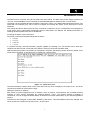
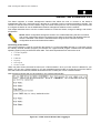
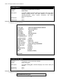
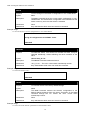
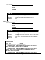
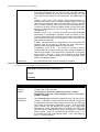
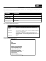
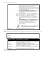
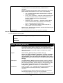
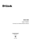
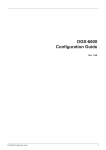
With the serial port properly connected to a management computer, the following screen should be visible. If this
screen does not appear, try pressing Ctrl+r to refresh the console screen.
[
Figure 1–1. Initial CLI screen
The initial username is admin (lower case). Press the Enter key twice to display the CLI input cursor. This is the
command line where all commands are input.
Setting the Switch’s IP Address
Each Switch must be assigned its own IP Address, which is used for communication with an SNMP network
manager or other TCP/IP application (for example BOOTP, TFTP). The Switch’s default IP address is
10.90.90.90. You can change the default Switch IP address to meet the specification of your networking address
scheme.
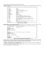
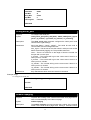
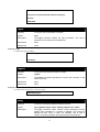
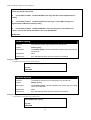
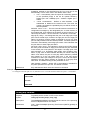
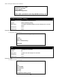
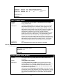
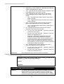
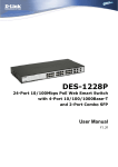
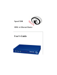
The Switch is also assigned a unique MAC address by the factory. This MAC address cannot be changed, and
can be found on the initial boot console screen – shown below.
1
DGS-3100 Gigabit Ethernet Switch Manual
Figure 1–2. Boot Screen
The Switch’s MAC address can also be found in the Web management program on the Device Information
window on the Configuration menu.
The IP address for the Switch must be set before it can be managed with the Web-based manager. The Switch
IP address can be automatically set using BOOTP or DHCP protocols, in which case the actual address
assigned to the Switch must be known.
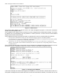
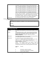
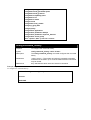
The IP address may be set using the Command Line Interface (CLI) over the console serial port as follows:
1. Starting at the command line prompt, enter the commands config ipif System vlan default ipaddress
xxx.xxx.xxx.xxx/yyy.yyy.yyy.yyy. Where the x’s represent the IP address to be assigned to the IP interface named
System and the y’s represent the corresponding subnet mask.
2. Alternatively, you can enter config ipif System ipaddress xxx.xxx.xxx.xxx/z. Where the x’s represent the IP
address to be assigned to the IP interface named System and the z represents the corresponding number of subnets
in CIDR notation.
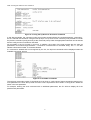
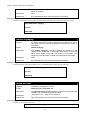
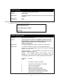
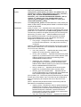
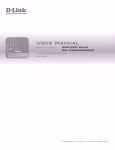
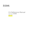
The IP interface named System on the Switch can be assigned an IP address and subnet mask which can then
be used to connect a management station to the Switch’s Telnet or Web-based management agent.
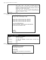
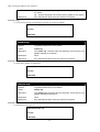
Figure 1–3. Assigning an IP Address
In the above example, the Switch was assigned an IP address of 10.53.13.26 with a subnet mask of 255.0.0.0.
The system message Success indicates that the command was executed successfully. The Switch can now be
2
configured and managed via Telnet, SNMP MIB browser and the CLI or via the Web-based management agent
using the above IP address to connect to the Switch.
NOTE: The DGS-3100 series of switches have the capability to be configured for an IP address
of 0.0.0.0, or, in essence, have no IP address. This function maybe used to disable Layer 3
functions of the Switch. When the IP address is set to 0.0.0.0 (invalid IP address), the Switch can
only be managed through the console port or SIM. Other management applications such as
Telnet, Web-based and SNMP cannot be used to manage the Switch when its IP address is
0.0.0.0.
3
DGS-3100 Gigabit Ethernet Switch Manual
2
USING THE CONSOLE CLI
The Switch supports a console management interface that allows the user to connect to the Switch’s
management agent via a serial port and a terminal or a computer running a terminal emulation program. The
console can also be used over the network using the TCP/IP Telnet protocol. The console program can be used
to configure the Switch to use an SNMP-based network management software over the network.
This chapter describes how to use the console interface to access the Switch, change its settings, and monitor
its operation.
NOTE: Switch configuration settings are saved to non-volatile RAM using the save command.
The current configuration will then be retained in the Switch’s NV-RAM, and reloaded when the
Switch is rebooted. If the Switch is rebooted without using the save command, the last
configuration saved to NV-RAM will be loaded.
Connecting to the Switch
The console interface is used by connecting the Switch to a VT100-compatible terminal or a computer running
an ordinary terminal emulator program (for example, the HyperTerminal program included with the Windows
operating system) using an RS-232C serial cable. Your terminal parameters will need to be set to:
•
VT-100 compatible
•
9600 bps
•
8 data bits
•
No parity
•
One stop bit
• No flow control
Users may also access the same functions over a Telnet interface. Once you have set an IP address for your
Switch, you can use a Telnet program (in VT-100 compatible terminal mode) to access and control the Switch.
All of the screens are identical, whether accessed from the console port or from a Telnet interface.
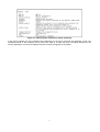
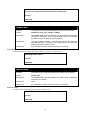
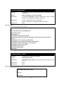
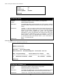
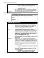
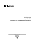
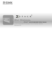
After the Switch reboots and you have logged in, the console looks like this:
Figure 2–1. Initial Console Screen after Logging In
4
Commands are entered at the command prompt, DGS3100#.
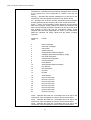
There are a number of helpful features included in the CLI. Entering the ? command will display a list of all of the
top-level commands.
Figure 2–2. The ? Command
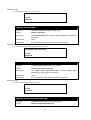
When entering a command without its required parameters, the CLI displays the prompt: command: config
account message and the options listed below.
Figure 2–3. Example Command Parameter Help
In this case, the command config account was entered with the parameter <username>. The CLI will then
prompt to enter the <username> with the message, command: config account. Every command in the CLI has
this feature, and complex commands have several layers of parameter prompting.
In addition, after typing any given command plus one space, users can see all of the next possible subcommands, in sequential order, by pressing the ? key.
To re-enter the previous command at the command prompt, press the up arrow cursor key. The previous
command will appear at the command prompt.
5
DGS-3100 Gigabit Ethernet Switch Manual
Figure 2–4. Using the Up Arrow to Re-enter a Command
In the above example, the command config account was entered without the required parameter <username>,
the CLI returned the command: config account prompt. The up arrow cursor control key was pressed to re-enter
the previous command (config account) at the command prompt. Now the appropriate username can be entered
and the config account command re-executed.
All commands in the CLI function in this way. In addition, the syntax of the help prompts are the same as
presented in this manual angle brackets < > indicate a numerical value or character string. The < > can also
indicate a Word with number fo character allowed.
If a command is entered that is unrecognized by the CLI, the top-level commands will be displayed under the
Available commands: prompt.
Figure 2–5. Available Commands
The top-level commands consist of commands such as show or config. Most of these commands require one or
more parameters to narrow the top-level command. This is equivalent to show what? or config what? Where the
what? is the next parameter.
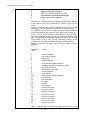
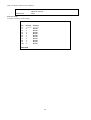
For example, entering the show command with no additional parameters, the CLI will then display all of the
possible next parameters.
6
Figure 2–6. Next possible completions: Show Command
In the above example, all of the possible next parameters for the show command are displayed. At the next
command prompt in the example, the up arrow was used to re-enter the show command, followed by the
account parameter. The CLI then displays the user accounts configured on the Switch.
7
DGS-3100 Gigabit Ethernet Switch Manual
3
COMMAND SYNTAX
The following symbols are used to describe how command entries are made and values and arguments are
specified in this manual. The online help contained in the CLI and available through the console interface uses
the same syntax.
NOTE: All commands are case-sensitive. Be sure to disable Caps Lock or any other unwanted
function that changes text case.
<angle brackets>
Purpose
Encloses a variable or value that must be specified.
Syntax
create account [admin | user] <username 15>
Description
In the above syntax example, users must supply a username in the
<username> space. Do not type the angle brackets.
Example
Command
create account admin newadmin1
[square brackets]
Purpose
Encloses a required value or set of required arguments. One value
or argument can be specified.
Syntax
create account [admin | user] <username 15>
Description
In the above syntax example, you must specify either an admin or a
user level account to be created. Do not type the square brackets.
Example
Command
create account user newuser1
| vertical bar
Purpose
Separates two or more mutually exclusive items in a list, one of
which must be entered.
Syntax
create account [admin | user] <username 15>
Description
In the above syntax example, users must specify either admin, or
user. Do not type the vertical bar.
Example
Command
create account user newuser1
All commands are case-sensitive. Be sure to disable Caps Lock or any other unwanted function that changes
text case.
8
{braces}
Purpose
Encloses an optional value or set of optional arguments.
Syntax
reset {[config | system]}
Description
In the above syntax example, users have the option to specify config
or system. It is not necessary to specify either optional value,
however the effect of the system reset is dependent on which, if any,
value is specified. Therefore, with this example there are three
possible outcomes of performing a system reset. See the following
chapter, Basic Commands for more details about the reset
command.
Example
command
reset config
Line Editing Key Usage
Delete
Deletes the character under the cursor and then shifts the
remaining characters in the line to the left.
Backspace
Deletes the character to the left of the cursor and then shifts the
remaining characters in the line to the left.
Insert or Ctrl+R
Toggle on and off. When toggled on, inserts text and shifts previous
text to the right.
Left Arrow
Moves the cursor to the left.
Right Arrow
Moves the cursor to the right.
Up Arrow
Repeats the previously entered command. Each time the up arrow
is pressed, the command previous to that displayed appears. This
way it is possible to review the command history for the current
session. Use the down arrow to progress sequentially forward
through the command history list.
Down Arrow
The down arrow will display the next command in the command
history entered in the current session. This displays each command
sequentially as it was entered. Use the up arrow to review previous
commands.
Tab
Shifts the cursor to the next field to the left.
Multiple Page Display Control Keys
Space
Displays the next page.
CTRL+c
Stops the display of remaining pages when multiple pages are to be
displayed.
ESC
Stops the display of remaining pages when multiple pages are to be
displayed.
n
Displays the next page.
p
Displays the previous page.
9
DGS-3100 Gigabit Ethernet Switch Manual
q
Stops the display of remaining pages when multiple pages are to be
displayed.
r
Refreshes the pages currently displayed.
a
Displays the remaining pages without pausing between pages.
Enter
Displays the next line or table entry.
10
4
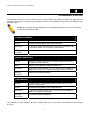
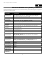
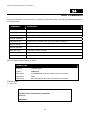
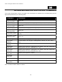
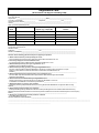
BASIC SWITCH COMMANDS
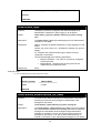
The Basic Switch commands in the Command Line Interface (CLI) are listed (along with the appropriate
parameters) in the following table.
Command
Parameter
create account
[admin | user] <username 15>
config account
<username 15>
show account
show session
show switch
show serial_port
config serial_port
{baud_rate [9600 | 19200 | 38400] auto_logout [never | 2_minutes | 5_minutes|
10_minutes | 15_minutes]}
enable clipaging
disable clipaging
delete account
<username 15>
enable web
<tcp_port_number 1-65535>
disable web
save
reboot
<box_id 1-6>
reset
login
logout
ping
<ipaddr> {times <value 1-255>} {timeout <sec 1-99>}
show cpu utilization
show configuration
[running | startup]
enable jumbo_frame
disable jumbo_frame
show jumbo_frame
locate
Each command is listed in detail, as follows:
11
DGS-3100 Gigabit Ethernet Switch Manual
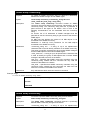
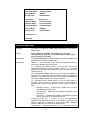
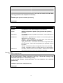
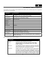
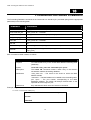
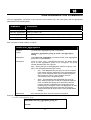
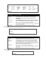
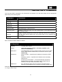
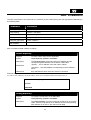
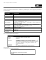
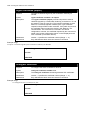
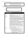
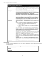
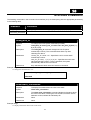
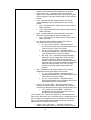
create account
Purpose
To create user accounts.
Syntax
create account [admin | user] <username 15>
The create account command creates an administrator or user
account that consists of a username and an optional password. Up
to 31 accounts can be created. The system prompts for the
account’s password, which may be between 0 and 15 characters.
admin − creates an administrator account.
user − creates a user account.
<username 1-15> − The account username may be between 1 and
15 characters.
Description
Parameters
Restrictions
Only Administrator-level users can issue this command.
Example usage:
To create an administrator-level user account with the username “dlink”:
DGS3100# create account admin dlink
Enter a case-sensitive password:****
Enter the password again for confirmation:****
Success.
DGS3100#
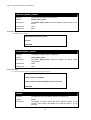
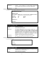
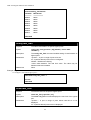
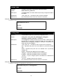
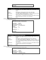
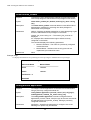
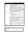
config account
Purpose
To change the password for an existing user account.
Syntax
config account <username 15>
Description
The config account command changes the password for a user
account that has been created using the create account command.
The system prompts for the account’s new password, which may be
between 0 and 15 characters.
Parameters
<username 1-15> − the account username.
Restrictions
Only Administrator-level users can issue this command.
Example usage:
To configure the user password of “dlink” account:
DGS3100# config account dlink
Enter a case-sensitive new password:****
Enter the new password again for confirmation:****
Success.
DGS3100#
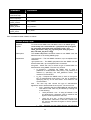
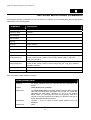
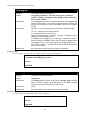
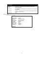
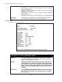
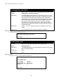
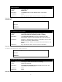
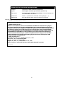
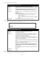
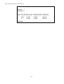
show account
Purpose
To display information about all user accounts on the Switch.
12
Syntax
show account
Description
The show account command displays all account usernames and
their access levels created on the Switch. Up to 31 user accounts
can exist on the Switch at one time.
Parameters
None.
Restrictions
None.
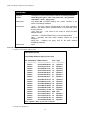
Example usage:
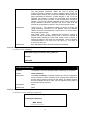
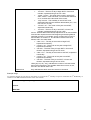
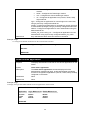
To display the accounts that have been created:
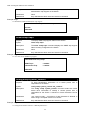
DGS3100# show account
Access Level
Username
------------------------ -------------------User
Dlink
Admin
admin
Total Entries: 2
DGS3100#
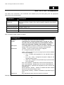
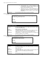
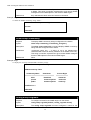
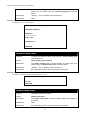
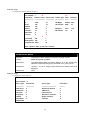
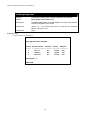
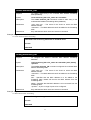
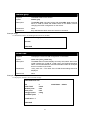
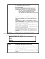
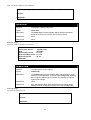
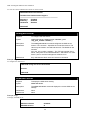
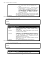
show session
Purpose
To display information about currently logged-in users.
Syntax
show session
Description
The show session command displays a list of all the users that are
logged-in at the time the command is issued. The information
includes the session ID (0 for the first logged-in user, 1 for the next
logged-in user, etc.), the Protocol used to connect to the Switch, the
user’s IP address, the user’s access Level (1=user, 15=admin), and
the account name on the Switch.
Parameters
None.
Restrictions
None.
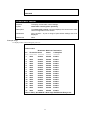
Example usage:
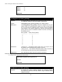
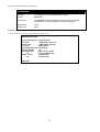
To display the way users logged in:
DGS3100# show session
From
Level
Name
ID
Protocol
------- ------------------- --------------------- -------- ----------------0
HTTP
10.6.10.43
15
admin
1
HTTP
10.6.10.43
15
admin
2
Telnet
10.6.60.13
15
admin
DGS3100#
13
DGS-3100 Gigabit Ethernet Switch Manual
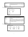
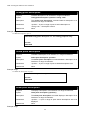
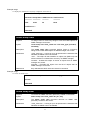
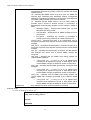
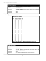
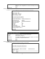
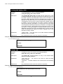
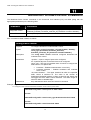
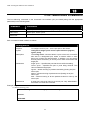
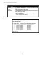
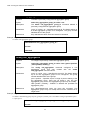
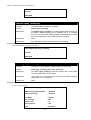
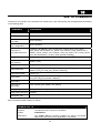
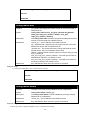
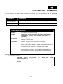
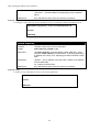
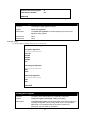
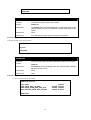
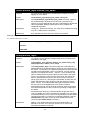
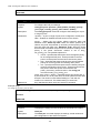
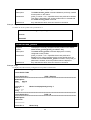
show switch
Purpose
To display information about the Switch.
Syntax
show switch
Description
The show switch command displays information about the Switch
settings, including Device Type, MAC Address, IP configuration,
Hardware/Software version, System information, and Switch
Network configuration.
Parameters
None.
Restrictions
None.
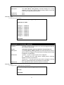
Example usage:
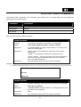
To display the Switch information:
DGS3100# show switch
Device Type
MAC Address
IP Address
VLAN Name
Subnet Mask
Default Gateway
Boot PROM Version
Firmware Version
Hardware Version
System Name
System Location
System Contact
Spanning Tree
GVRP
IGMP Snooping
TELNET
WEB
: DGS-3100 Gigabit-Ethernet Switch
: DA-10-21-00-00-01
: 10.6.41.104
: default
: 255.255.255.224
: 10.6.41.97
: 1.0.0.03
: 1.00.29
: 00.00.01
: DGS-3100
: 7th_flr_east_cabinet
: Julius_Erving_212-555-6666
: Enabled
: Disabled
: Disabled
: Enabled
: Enabled (TCP 80)
DGS3100#
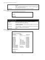
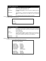
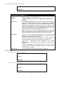
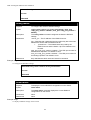
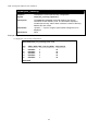
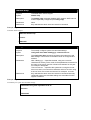
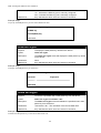
show serial_port
Purpose
To display the current serial port settings.
Syntax
show serial_port
Description
The show serial_port command displays the current serial port
settings.
Parameters
None.
Restrictions
None.
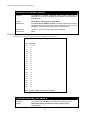
Example usage:
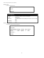
To display the serial port settings:
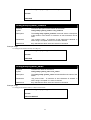
DGS3100# show serial_port
14
Baud Rate
Data Bits
Parity Bits
Stop Bits
Auto-Logout
: 9600
:8
: None
:1
: 10 mins
DGS3100#
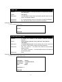
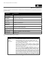
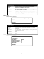
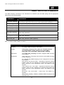
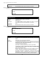
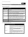
config serial_port
Purpose
To configure the serial port.
Syntax
config serial_port {baud_rate [9600 | 19200 | 38400] auto_logout
[never | 2_minutes | 5_minutes| 10_minutes | 15_minutes]}
Description
The show serial_port command configures the serial port’s baud
rate and auto logout settings.
Parameters
baud rate [9600 | 19200 | 38400] − The serial bit rate used to
communicate with the management host.
auto_logout - The amount of time the Switch’s serial port can be idle
before automatically logging out. The possible values are:
never − There is no time limit on the length of time the console can
be open with no user input.
2_minutes − The console will log out the current user if there is no
user input for 2 minutes.
5_minutes − The console will log out the current user if there is no
user input for 5 minutes.
10_minutes − The console will log out the current user if there is no
user input for 10 minutes.
15_minutes − The console will log out the current user if there is no
user input for 15 minutes.
Restrictions
Only administrator-level users can issue this command.
Example usage:
To configure the baud rate:
DGS3100# config serial_port baud_rate 9600
Success.
DGS3100#
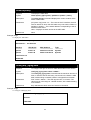
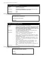
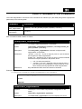
enable clipaging
Purpose
To pause the scrolling of the console screen after each page when a
show command displays more than one page.
Syntax
enable clipaging
Description
The enable clipaging command pauses the scrolling of the console
screen at the end of each page when issuing a command which
15
DGS-3100 Gigabit Ethernet Switch Manual
would display more than one screen of information. The default
setting is enabled.
Parameters
None.
Restrictions
Only administrator-level users can issue this command.
Example usage:
To enable pausing of the screen display when the show command output reaches the end of the page:
DGS3100# enable clipaging
Success.
DGS3100#
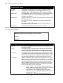
disable clipaging
Purpose
To disable the pausing of the console screen scrolling at the end of
each page when the command displays more than one screen of
information.
Syntax
disable clipaging
Description
The disable clipaging command disables the pausing of the
console screen at the end of each page when issuing a command
which would display more than one screen of information. This
causes the console screen to rapidly scroll through several pages.
Parameters
None.
Restrictions
Only administrator-level users can issue this command.
Example usage:
To disable pausing of the screen display when a command output reaches the end of the page:
DGS3100# disable clipaging
Success.
DGS3100#
delete account
Purpose
To delete an existing user account.
Syntax
delete account <username 15>
Description
Parameters
The delete account command deletes a user account that has been
created using the create account command.
<username 1-15> − the account username.
Restrictions
Only Administrator-level users can issue this command.
Example usage:
To delete the user account “System”:
DGS3100# delete account System
16
Are you sure to delete the last administrator account?(y/n)
Success.
DGS3100#
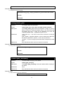
enable web
Purpose
To enable the HTTP-based management software on the Switch.
Syntax
enable web <tcp_port_number 1-65535>
Description
The enable web command enables the Web-based management
software on the Switch. The user can specify the TCP port number
the Switch will use to listen for Telnet requests.
Parameters
<tcp_port_number 1-65535> − The TCP port number. TCP ports are
numbered between 1 and 65535. The “well-known” port for the Webbased management software is 80.
Restrictions
Only administrator-level users can issue this command.
Example usage:
To enable HTTP and configure the TCP port number to listen for Telnet requests:
DGS3100# enable web 80
Success.
DGS3100#
disable web
Purpose
To disable the HTTP-based management software on the Switch.
Syntax
disable web
Description
The disable web command disables the Web-based management
software on the Switch.
Parameters
None.
Restrictions
Only administrator-level users can issue this command.
Example usage:
To disable HTTP-based management software on the Switch:
DGS3100# disable web
Success.
DGS3100#
17
DGS-3100 Gigabit Ethernet Switch Manual
save
Purpose
To save changes in the Switch’s configuration to non-volatile RAM.
Syntax
save
Description
The save command saves the current switch configuration to nonvolatile RAM. The saved switch configuration will be loaded into the
Switch’s memory each time the Switch is restarted.
Parameters
None.
Restrictions
Only administrator-level users can issue this command.
Example usage:
To save the Switch’s current configuration to non-volatile RAM:
DGS3100# save
Saving all configurations to NV-RAM... Done.
DGS3100#
reboot
Purpose
To restart the Switch. If the Switch is a member of a stack, it may be
rebooted individually, without affecting the other members of the
stack.
Syntax
reboot <box_id 1-6>
Description
The reboot command restarts the Switch.
Parameters
<box_id 1-6> − The unit’s current stack membership number.
Restrictions
Only Administrator-level users can issue this command.
Example usage:
To restart the Switch unit 1:
DGS3100# reboot 1
DGS3100#
reset
Purpose
To reset the Switch to the factory default settings.
Syntax
reset
Description
The reset command restores the Switch’s configuration to the
default settings assigned from the factory. Execution of the reset
command through the CLI retains the unit’s current stack
membership number.
Parameters
None.
Restrictions
Only administrator-level users can issue this command.
Example usage:
To restore all of the Switch’s parameters to their default values:
18
DGS3100# reset
Are you sure to proceed with system reset?(y/n)
Success.
DGS3100#
login
Purpose
To log in a user to the Switch’s console.
Syntax
login
Description
The login command initiates the login procedure. The user is
prompted for the Username and Password.
Parameters
None.
Restrictions
None.
Example usage:
To initiate the login procedure:
DGS3100# login
UserName:
logout
Purpose
To log out a user from the Switch’s console.
Syntax
Logout
Description
The logout command terminates the current user’s session on the
Switch’s console.
Parameters
None.
Restrictions
None.
Example usage:
To terminate the current user’s console session:
DGS3100# logout
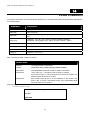
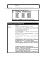
ping
Purpose
To test the connectivity between network devices.
Syntax
ping <ipaddr> {times <value 1-255>} {timeout <sec 1-99>}
Description
The ping command sends Internet Control Message Protocol
(ICMP) echo messages to a remote IP address. The remote IP
address will then “echo” or return the message. This is used to
confirm connectivity between the Switch and the remote device.
19
DGS-3100 Gigabit Ethernet Switch Manual
Parameters
<ipaddr> - The IP address of the host.
times <value 1-255> - The number of individual ICMP echo
messages to be sent. The maximum value is 255. The default is 0.
Pinging an IP address without the times parameter will ping the
target device an infinite number of times.
timeout <sec 1-99> - The time-out period while waiting for a
response from the remote device. A value of 1 to 99 seconds can be
specified. The default is 1 second.
Restrictions
None.
Example usage:
To ping the IP address 10.6.150.34 three times:
DGS3100# ping 10.6.150.34 times 3
Pinging 10.6.150.34 with 56 bytes of data:
56 bytes from 10.6.150.34: icmp_seq=1. time=0 ms
56 bytes from 10.6.150.34: icmp_seq=2. time=0 ms
56 bytes from 10.6.150.34: icmp_seq=3. time=0 ms
----10.6.150.34 PING Statistics---3 packets transmitted, 3 packets received, 0% packet loss
round-trip (ms) min/avg/max = 0/0/0
Success.
DGS3100#
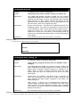
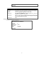
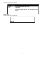
show cpu utilization
Purpose
To measure CPU utilization.
Syntax
show cpu utilization
Description
The show cpu utilization command displays information about
CPU utilization.
Parameters
None.
Restrictions
None.
Example usage:
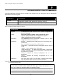
To show CPU utilization information:
DGS3100# show cpu utilization
CPU utilization service is on.
CPU utilization
---------------------five seconds:2% ;one minute:1% ;five minutes:1%
DGS3100#
20
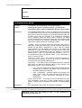
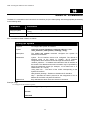
show configuration
Purpose
To display the current or saved version of the configuration settings
of the Switch.
Syntax
show configuration [running | startup]
Description
The show configuration command displays the current or saved
version of the configuration settings of the Switch.
Parameters
running – Displays the current configuration.
startup – Displays the configuration saved in NV-RAM.
Restrictions
None.
Example usage:
To show current configuration information:
DGS3100# show configuration running
config snmp system_name DGS-3100
create vlan 2 tag 2
enable 802.1x
config 802.1x auth_protocol radius
config radius add 10.6.41.226 key 123456 auth_port 1812 acct_port 1813 priori
ty first
config ports (1-2,4-7) enable_reauth enable
config ports 3 port_control auto enable_reauth enable
config 802.1x auth_mode ports (1-7) mac_based
config guest_vlan 2 state enable
config guest_vlan ports 3
config ipif system dhcp
DGS3100#
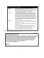
enable jumbo_frame
Purpose
To enable jumbo frames on the device.
Syntax
enable jumbo_frame
Description
The enable jumbo_frame command enables jumbo frames on the
device.
Parameters
None.
Restrictions
None.
Example usage:
To enable jumbo frames:
DGS3100# enable jumbo_frame
Success.
DGS3100#
21
DGS-3100 Gigabit Ethernet Switch Manual
disable jumbo_frame
Purpose
To disable jumbo frames on the device.
Syntax
disable jumbo_frame
Description
The disable jumbo_frame command disables jumbo frames on the
device.
Parameters
None.
Restrictions
None.
Example usage:
To disable jumbo_frames:
DGS3100# disable jumbo_frame
Success.
DGS3100#
show jumbo_frame
Purpose
To display the jumbo frame configuration.
Syntax
show jumbo_frame
Description
The show jumbo_frame command displays the jumbo frame
configuration.
Parameters
None.
Restrictions
None.
Example usage:
To show the jumbo_frames configuration status on the device:
DGS3100# show jumbo_frame
Jumbo frames are disabled.
Jumbo frames will be enabled after save and restart.
DGS3100#
locate
Purpose
To enable the user to locate the device he is working on.
Syntax
locate
Description
The locate command causes the seven segment display of the
currently active switch with Master ID to blink the letter L for 20
seconds.
22
Parameters
None.
Restrictions
None.
Example usage:
To display the currently active switch:
DGS3100# locate
Success.
DGS3100#
23
DGS-3100 Gigabit Ethernet Switch Manual
5
SWITCH PORT COMMANDS
The Switch Port commands in the Command Line Interface (CLI) are listed (along with the appropriate
parameters) in the following table.
Command
Parameter
config ports
[all | <portlist>] {speed [auto | 10_half | 10_full | 100_half | 100_full | 1000_full] |
flow_control [enable | disable | auto] | learning [enable | disable] | state [enable |
disable]}
show ports
{<portlist>}
config ports description
<portlist> <string 1-64>
delete ports description
<portlist>
show ports description
{<portlist>}
Each command is listed in detail, as follows:
config ports
Purpose
To configure the Switch’s Ethernet port settings.
Syntax
config ports [all | <portlist>] {speed [auto | 10_half | 10_full |
100_half | 100_full | 1000_full] | flow_control [enable | disable |
auto] | learning [enable | disable] | state [enable | disable]}
Description
The config ports command configures the Switch’s Ethernet port
settings. Only the ports listed in the <portlist> will be affected.
Parameters
<portlist> − A port or range of ports to be configured.
all − Configures all ports on the Switch.
speed – Sets the speed of a port or range of ports, with the addition
of one of the following:
•
auto − Enables auto-negotiation for the specified range of
ports.
•
[10 | 100 | 1000] − Configures the speed in Mbps for the
specified range of ports.
•
[half | full] − Configures the specified range of ports as either
full or half-duplex.
flow_control [enable] – Enables flow control for the specified ports.
flow_control [disable] – Disables flow control for the specified ports.
flow_control [auto] – Specifies auto-negotiation of flow control for the
specified ports.
learning [enable | disable] − Enables or disables the MAC address
learning on the specified range of ports.
state [enable | disable] − Enables or disables the specified range of
ports.
Restrictions
Only administrator-level users can issue this command.
Example usage:
24
To configure the speed of ports 1-3 to be 10 Mbps, full duplex, learning and state enabled:
DGS3100# config ports 1-3 speed 10_full learning enable state enable
Success.
DGS3100#
show ports
Purpose
To display the current configuration of a range of ports.
Syntax
show ports {<portlist>}
Description
The show ports command displays the current configuration of a
port or range of ports.
Parameters
<portlist> − A port or range of ports whose settings are to be
displayed.
Restrictions
None.
Example usage:
To display the configuration of all ports on the Switch:
DGS3100# show ports
Port
----1:1
1:2
1:3
1:4
1:5
1:6
1:7
1:8
1:9
1:10
1:11
1:12
1:13
1:14
1:15
1:16
1:17
1:18
1:19
Port
State
-----------Enabled
Enabled
Enabled
Enabled
Enabled
Enabled
Enabled
Enabled
Enabled
Enabled
Enabled
Enabled
Enabled
Enabled
Enabled
Enabled
Enabled
Enabled
Enabled
Settings
Connection
Speed/Duplex/FlowCtrl Speed/Duplex/FlowCtrl
----------------------------------------------------------Auto/Disabled
Link Down
Auto/Disabled
Link Down
Auto/Disabled
100M/Full/Disabled
Auto/Disabled
100M/Full/Disabled
Auto/Disabled
Link Down
Auto/Disabled
Link Down
Auto/Disabled
Link Down
Auto/Disabled
Link Down
Auto/Disabled
Link Down
Auto/Disabled
Link Down
Auto/Disabled
Link Down
Auto/Disabled
Link Down
Auto/Disabled
Link Down
Auto/Disabled
Link Down
Auto/Disabled
Link Down
Auto/Disabled
Link Down
Auto/Disabled
Link Down
Auto/Disabled
Link Down
Auto/Disabled
Link Down
DGS3100#
25
Address
Learning
----------Enabled
Enabled
Enabled
Enabled
Enabled
Enabled
Enabled
Enabled
Enabled
Enabled
Enabled
Enabled
Enabled
Enabled
Enabled
Enabled
Enabled
Enabled
Enabled
DGS-3100 Gigabit Ethernet Switch Manual
config ports description
Purpose
To add a description to an interface or ranges of interface.
Syntax
config ports description <portlist> <string 1-64>
Description
The config ports description command adds a description to an
interface or a range of interfaces.
Parameters
<portlist> − A port or range of ports to add a description to.
<string 1-64> − Description content.
Restrictions
None.
Example usage:
To add a description to port 1:
DGS3100# config ports description 1:1 "For testing purposes only"
Success.
DGS3100#
delete ports description
Purpose
To delete a description of an interface or a range of interfaces.
Syntax
delete ports description <portlist>
Description
The delete ports description command deletes a description of an
interface or a range of interfaces.
Parameters
<portlist> − A port or range of ports to delete descriptions from.
Restrictions
None.
Example usage:
To delete the description of port 1:
DGS3100# delete ports description 1:1
Success.
DGS3100#
show ports description
Purpose
To display a description of an interface or a range of interfaces.
Syntax
show ports description {<portlist>}
Description
The show ports description command displays a description of an
interface or a range of interfaces.
Parameters
<portlist> − A port or range of ports whose descriptions are to be
displayed.
Restrictions
None.
Example usage:
26
To display the description of port 1:
DGS3100# show ports description 1:1
Port
Description
------------- ----------------1:1
For testing purposes only
DGS3100#
27
DGS-3100 Gigabit Ethernet Switch Manual
6
NETWORK MANAGEMENT (SNMP) COMMANDS
The Network Management commands in the Command Line Interface (CLI) are listed (along with the appropriate
parameters) in the following table.
Command
Parameter
create snmp user
<username 24> <groupname 30> [encrypted [by_password auth [md5
<auth_password 1-32> | sha <auth_password 1-32>] | by_key auth [md5
<auth_key 32 or 64>| sha<auth_key 40 or 72>]]]
delete snmp user
<username 24>
show snmp user
create snmp view
<view_name 30> <oid> view_type [included | excluded]
delete snmp view
<view_name 30> [all | oid]
show snmp view
{<view_name 30>}
create snmp
community
<community_string 20> view <view_name 30> [read_only | read_write]
delete snmp
community
<community_string 20>
show snmp community
{<community_string 20>}
config snmp engineID
[default | <snmp_engineID 10-64>]
show snmp engineID
create snmp group
<groupname 30> [v1 | v2c | v3 [noauth_nopriv | auth_nopriv |
auth_priv]{notify_view <view_name 30>}] {read_view <view_name 30> |
write_view <view_name 30>}
delete snmp group
<groupname 30>
show snmp groups
create snmp host
<ipaddr> [v1<community_string 20> | v2c<community_string 20> | v3
[noauth_nopriv | auth_nopriv | auth_priv]<auth_string 24>]
delete snmp host
<ipaddr>
show snmp host
{<ipaddr>}
create trusted_host
<ipaddr>
show trusted_host
{<ipaddr>}
delete trusted_host
<ipaddr>
enable snmp traps
disable snmp traps
enable snmp
authenticate trap
28
Command
Parameter
disable snmp
authenticate trap
show snmp traps
config snmp
system_contact
<sw_contact>
config snmp
system_location
<sw_location>
config snmp
system_name
<sw_name>
Each command is listed in detail, as follows:
create snmp user
Purpose
To create a new SNMP user and add the user to an SNMP group.
Syntax
create snmp user <username 24> <groupname 30> [encrypted
[by_password auth [md5 <auth_password 1-32> | sha
<auth_password 1-32>] | by_key auth [md5 <auth_key 32 or
64>| sha<auth_key 40 or 72>]]]
Description
The create snmp user command creates a new SNMP user and
adds the user to an existing SNMP group.
Parameters
<username 24> − The new SNMP username, up to 24 alphanumeric
characters.
<groupname 30> − The SNMP groupname the new SNMP user will
be associated with, up to 30 alphanumeric characters.
encrypted – Allows the user to choose a type of authorization for
authentication using SNMP. The user may choose:
•
by_password – Requires the SNMP user to enter a
password for authentication and privacy. The password is
defined by specifying the auth_password below. This
method is recommended.
•
by_key – Requires the SNMP user to enter an encryption
key for authentication and privacy. The key is defined by
specifying the key in hex form below. This method is not
recommended.
auth - The user may also choose the type of authentication
algorithms used to authenticate the snmp user. The choices are:
•
•
md5 − Specifies that the HMAC-MD5-96 authentication
level will be used. md5 may be utilized by entering one
of the following:
•
<auth password 1-32> - A string of between 1 and
32 alphanumeric characters used to authorize the
agent to receive packets for the host.
•
<auth_key 32 or 64> - A string of exactly 32 or 64
alphanumeric characters, in hex form, to define the
key used to authorize the agent to receive packets
for the host.
sha − Specifies that the HMAC-SHA-96 authentication
29
DGS-3100 Gigabit Ethernet Switch Manual
level will be used.
Restrictions
•
<auth password 1-32> - A string of between 1 and
32 alphanumeric characters used to authorize the
agent to receive packets for the host.
•
<auth_key 40 or 72> - A string of exactly 40 or 72
alphanumeric characters, in hex form, to define the
key used to authorize the agent to receive packets
for the host.
Only administrator-level users can issue this command.
Example usage:
To create an SNMP user on the Switch:
DGS3100# create snmp user dlink default encrypted by_password
auth md5 auth_password priv none
Success.
DGS3100#
delete snmp user
Purpose
To remove an SNMP user from an SNMP group and also to delete
the associated SNMP group.
Syntax
delete snmp user <username 24>
Description
The delete snmp user command removes an SNMP user from its
SNMP group and then deletes the associated SNMP group.
Parameters
<username 24> − A string of up to 24 alphanumeric characters that
identifies the SNMP user to be deleted.
Restrictions
Only administrator-level users can issue this command.
Example usage:
To delete a previously created SNMP user on the Switch:
DGS3100# delete snmp user dlink
Success.
DGS3100#
show snmp user
Purpose
To display information about each SNMP username in the SNMP
group username table.
Syntax
show snmp user
Description
The show snmp user command displays information about each
SNMP username in the SNMP group username table.
Parameters
None.
Restrictions
Only administrator-level users can issue this command.
30
Example usage:
To display the SNMP users currently configured on the Switch:
DGS3100# show snmp user
Username Group Name SNMP Version Auth-Protocol
--------------------------- --------------- -----------initial
V3
None
Initial
Total Entries: 1
DGS3100#
create snmp view
Purpose
To assign views to community strings to limit which MIB objects an
SNMP manager can access.
Syntax
create snmp view <view_name 30> <oid> view_type [included |
excluded]
Description
The create snmp view command assigns views to community
strings to limit which MIB objects an SNMP manager can access.
Parameters
<view_name 30> − A string of up to 30 alphanumeric characters that
identifies the SNMP view to be created.
<oid> − The object ID that identifies an object tree (MIB tree) that
will be included or excluded from access by an SNMP manager.
included − Includes this object in the list of objects that an SNMP
manager can access.
excluded − Excludes this object from the list of objects that an
SNMP manager can access.
Restrictions
Only administrator-level users can issue this command.
Example usage:
To create an SNMP view:
DGS3100# create snmp view dlinkview 1.3.6 view_type included
Success.
DGS3100#
delete snmp view
Purpose
To remove an SNMP view entry previously created on the Switch.
Syntax
delete snmp view <view_name 30> [all | oid]
Description
The delete snmp view command removes an SNMP view
previously created on the Switch.
Parameters
<view_name 30> − A string of up to 30 alphanumeric characters that
identifies the SNMP view to be deleted.
31
DGS-3100 Gigabit Ethernet Switch Manual
all − Specifies that all of the SNMP views on the Switch will be
deleted.
<oid> − The object ID that identifies an object tree (MIB tree) that
will be deleted from the Switch.
Restrictions
Only administrator-level users can issue this command.
Example usage:
To delete a previously configured SNMP view from the Switch:
DGS3100# delete snmp view dlinkview all
Success.
DGS3100#
show snmp view
Purpose
To display an SNMP view previously created on the Switch.
Syntax
show snmp view {<view_name 30>}
Description
The show snmp view command displays an SNMP view previously
created on the Switch.
Parameters
<view_name 30> − A string of up to 30 alphanumeric characters that
identifies the SNMP view to be displayed.
Restrictions
None.
Example usage:
To display SNMP view configuration:
DGS3100# show snmp view
Vacm View Table Settings
View Name
Subtree
View Type
-------------------------------------------- ---------ReadView
1
Included
WriteView
1
Included
NotifyView
1.3.6
Included
Restricted
1.3.6.1.2.1.1
Included
Restricted
1.3.6.1.2.1.11
Included
1.3.6.1.6.3.10.2.1 Included
restricted
1.3.6.1.6.3.11.2.1 Included
restricted
1.3.6.1.6.3.15.1.1 Included
restricted
1
Included
CommunityView
CommunityView
1.3.6.1.6.3
Excluded
CommunityView
1.3.6.1.6.3.1
Included
Total Entries: 11
DGS3100#
32
create snmp community
Purpose
To create an SNMP community string to define the relationship
between the SNMP manager and an SNMP agent.
Syntax
create snmp community <community_string 20> view
<view_name 30> [read_only | read_write]
Description
The create snmp community command creates an SNMP
community string and assigns access-limiting characteristics to this
community string. The community string acts like a password to
permit access to the agent on the Switch. One or more of the
following characteristics can be associated with the community
string:
An Access List of IP addresses of SNMP managers that are
permitted to use the community string to gain access to the Switch’s
SNMP agent.
An MIB view that defines the subset of all MIB objects to be
accessible to the SNMP community.
Read/write or read-only level permission for the MIB objects
accessible to the SNMP community.
Parameters
<community_string 20> − A string of up to 20 alphanumeric
characters that is used to identify members of an SNMP community.
This string is used like a password to give remote SNMP managers
access to MIB objects in the Switch’s SNMP agent.
<view_name 30> − A string of up to 30 alphanumeric characters that
is used to identify the group of MIB objects that a remote SNMP
manager is allowed to access on the Switch.
read_only − Specifies that SNMP community members using the
community string created with this command can only read the
contents of the MIBs on the Switch.
read_write − Specifies that SNMP community members using the
community string created with this command can read from and
write to the contents of the MIBs on the Switch.
Restrictions
Only administrator-level users can issue this command.
Example usage:
To create the SNMP community string “dlink:”
DGS3100# create snmp community dlink view ReadView read_write
Success.
DGS3100#
delete snmp community
Purpose
To remove a specific SNMP community string from the Switch.
Syntax
delete snmp community <community_string 20>
Description
The delete snmp community command removes a previously
defined SNMP community string from the Switch.
Parameters
<community_string 20> − A string of up to 20 alphanumeric
33
DGS-3100 Gigabit Ethernet Switch Manual
characters that is used to identify members of an SNMP community
to delete. This string is used like a password to give remote SNMP
managers access to MIB objects in the Switch’s SNMP agent.
Restrictions
Only administrator-level users can issue this command.
Example usage:
To delete the SNMP community string “dlink”:
DGS3100# delete snmp community dlink
Success.
DGS3100#
show snmp community
Purpose
To display SNMP community strings configured on the Switch.
Syntax
show snmp community {<community_string 20>}
Description
The show snmp community command displays SNMP community
strings that are configured on the Switch.
Parameters
<community_string 20> − A string of up to 20 alphanumeric
characters that is used to identify members of an SNMP community.
This string is used like a password to give remote SNMP managers
access to MIB objects in the Switch’s SNMP agent.
Restrictions
None.
Example usage:
To display the currently entered SNMP community strings:
DGS3100# show snmp community
SNMP Community Table
View Name
Access Right
Community Name
-------------------------------- -------------------------- -----------------------dlink
ReadView
read write
CommunityView
read write
private
CommunityView
read only
public
Total Entries: 3
DGS3100#
config snmp engineID
Purpose
To configure a name for the SNMP engine on the Switch.
Syntax
config snmp engineID [default | <snmp_engineID 10-64>]
Description
The config snmp engineID command configures a name for the
34
SNMP engine on the Switch.
Parameters
default − defines the automatically created engineID based on the
device mac.
<snmp_engineID 10-64> − A string, of between 10 and 64
alphanumeric characters, to be used to identify the SNMP engine on
the Switch.
Restrictions
Only administrator-level users can issue this command.
Example usage:
To give the SNMP agent on the Switch the name “0035636666”
DGS3100# config snmp engineID 0035636666
Success.
DGS3100#
show snmp engineID
Purpose
To display the identification of the SNMP engine on the Switch.
Syntax
show snmp engineID
Description
The show snmp engineID command displays the identification of
the SNMP engine on the Switch.
Parameters
None.
Restrictions
None.
Example usage:
To display the current name of the SNMP engine on the Switch:
DGS3100# show snmp engineID
SNMP Engine ID : 0035636666
DGS3100#
create snmp group
Purpose
To create a new SNMP group, or a table that maps SNMP users to
SNMP views.
Syntax
create snmp group <groupname 30> [v1 | v2c | v3
[noauth_nopriv | auth_nopriv | auth_priv]{notify_view
<view_name 30>}] {read_view <view_name 30> | write_view
<view_name 30>}
Description
The create snmp group command creates a new SNMP group, or
a table that maps SNMP users to SNMP views.
Parameters
<groupname 30> − A name of up to 30 alphanumeric characters that
identifies the SNMP group the new SNMP user is to be associated
with.
v1 – Specifies that SNMP version 1 is to be used. The Simple
35
DGS-3100 Gigabit Ethernet Switch Manual
Network Management Protocol (SNMP), version 1, is a network
management protocol that provides a means to monitor and control
network devices.
v2c – Specifies that SNMP version 2c is to be used. The SNMP v2c
supports both centralized and distributed network management
strategies. It includes improvements in the Structure of Management
Information (SMI) and adds some security features.
v3 – Specifies that the SNMP version 3 is to be used. SNMP v3
provides secure access to devices through a combination of
authentication and encrypting packets over the network. SNMP v3
adds:
•
Message integrity − Ensures that packets have not been
tampered with during transit.
•
Authentication − Determines if an SNMP message is from a
valid source.
•
Encryption − Scrambles the contents of messages to
prevent it from being viewed by an unauthorized source.
noauth_nopriv − Specifies that there is no authorization and no
encryption of packets sent between the Switch and a remote SNMP
manager.
auth_nopriv − Specifies that authorization is required, but there is no
encryption of packets sent between the Switch and a remote SNMP
manager.
auth_priv − Specifies that authorization is required, and that packets
sent between the Switch and a remote SNMP manger are
encrypted.
read_view – Specifies that the SNMP group being created can
request SNMP messages.
•
<view_name 30> − A string of up to 30 alphanumeric
characters that identifies the group of MIB objects that a
remote SNMP manager is allowed to access on the Switch.
write_view – Specifies that the SNMP group being created has write
privileges.
•
<view_name 30> − A string of up to 30 alphanumeric
characters that identifies the group of MIB objects that a
remote SNMP manager is allowed to access on the Switch.
notify_view − Specifies that the SNMP group being created can
receive SNMP trap messages generated by the Switch’s SNMP
agent.
•
Restrictions
<view_name 30> − A string of up to 30 alphanumeric
characters that identifies the group of MIB objects that a
remote SNMP manager is allowed to access on the Switch.
Only administrator-level users can issue this command.
Example usage:
To create an SNMP group named “sg1:”
DGS3100# create snmp group sg1 v3 noauth_nopriv read_view v1
write_view v1 notify_view v1
Success.
DGS3100#
36
delete snmp group
Purpose
To remove an SNMP group from the Switch.
Syntax
delete snmp group <groupname 30>
Description
The delete snmp group command removes an SNMP group from
the Switch.
Parameters
<groupname 30> − A string of up to 30 alphanumeric characters that
identifies the SNMP group the new SNMP user will be associated
with.
Restrictions
Only administrator-level users can issue this command.
Example usage:
To delete the SNMP group named “sg1”.
DGS3100# delete snmp group sg1
Success.
DGS3100#
show snmp groups
Purpose
To display the group-names of SNMP groups currently configured
on the Switch. The security model, level, and status of each group
are also displayed.
Syntax
show snmp groups
Description
The show snmp groups command displays the group-names of
SNMP groups currently configured on the Switch. The security
model, level, and status of each group are also displayed.
Parameters
None.
Restrictions
None.
Example usage:
To display the currently configured SNMP groups on the Switch:
DGS3100# show snmp groups
Vacm Access Table Settings
Group Name
: Group3
: ReadView
ReadView Name
: WriteView
WriteView Name
Notify View Name : NotifyView
: SNMPv3
Security Model
: NoAuthNoPriv
Security Level
Group Name
ReadView Name
WriteView Name
: Group4
: ReadView
: WriteView
37
DGS-3100 Gigabit Ethernet Switch Manual
Notify View Name
Security Model
Security Level
: NotifyView
: SNMPv3
: authNoPriv
Group Name
ReadView Name
WriteView Name
Notify View Name
Security Model
Security Level
: Group5
: ReadView
: WriteView
: NotifyView
: SNMPv3
: authNoPriv
Group Name
: Group6
ReadView Name
: ReadView
WriteView Name
: WriteView
Notify View Name : NotifyView
Security Model
: SNMPv3
Security Level
: authPriv
Group Name
: Group7
ReadView Name
: ReadView
WriteView Name
: WriteView
Notify View Name : NotifyView
: SNMPv3
Security Model
: authPriv
Security Level
: initial
Group Name
: restricted
ReadView Name
WriteView Name
:
Notify View Name : restricted
Security Model
: SNMPv3
Security Level
: NoAuthNoPriv
Group Name
: ReadGroup
ReadView Name
: CommunityView
WriteView Name
:
Notify View Name : CommunityView
Security Model
: SNMPv1
Security Level
: NoAuthNoPriv
Group Name
: ReadGroup
ReadView Name
: CommunityView
WriteView Name
:
Notify View Name : CommunityView
: SNMPv2
Security Model
: NoAuthNoPriv
Security Level
Group Name
ReadView Name
: WriteGroup
: CommunityView
38
WriteView Name
Notify View Name
Security Model
Security Level
: CommunityView
: CommunityView
: SNMPv1
: NoAuthNoPriv
Group Name
: WriteGroup
ReadView Name
: CommunityView
WriteView Name
: CommunityView
Notify View Name : CommunityView
Security Model
: SNMPv2
Security Level
: NoAuthNoPriv
Total Entries: 10
DGS3100#
create snmp host
Purpose
To create a recipient of SNMP traps generated by the Switch’s
SNMP agent.
Syntax
create snmp host <ipaddr> [v1<community_string 20> |
v2c<community_string 20> | v3 [noauth_nopriv | auth_nopriv |
auth_priv]<auth_string 24>]
Description
The create snmp host command creates a recipient of SNMP traps
generated by the Switch’s SNMP agent.
Parameters
<ipaddr> − The IP address of the remote management station to
serve as the SNMP host for the Switch.
v1 – Specifies that SNMP version 1 is to be used. The Simple
Network Management Protocol (SNMP), version 1, is a network
management protocol that provides a means to monitor and control
network devices.
v2c – Specifies that SNMP version 2c is to be used. The SNMP v2c
supports both centralized and distributed network management
strategies. It includes improvements in the Structure of Management
Information (SMI) and adds some security features.
v3 – Specifies that the SNMP version 3 is to be used. SNMP v3
provides secure access to devices through a combination of
authentication and encrypting packets over the network. SNMP v3
adds:
•
Message integrity − ensures that packets have not been
tampered with during transit.
•
Authentication − determines if an SNMP message is from a
valid source.
•
Encryption − scrambles the contents of messages to prevent
it being viewed by an unauthorized source.
<community_string 20> − A string of up to 20 alphanumeric
characters that identifies members of an SNMP community. This
string is used like a password to give remote SNMP managers
access to MIB objects in the Switch’s SNMP agent.
noauth_nopriv − Specifies that there is no authorization and no
39
DGS-3100 Gigabit Ethernet Switch Manual
encryption of packets sent between the Switch and a remote SNMP
manager.
auth_nopriv − Specifies that authorization is required, but there is no
encryption of packets sent between the Switch and a remote SNMP
manager.
auth_priv − Specifies that authorization is required, and that packets
sent between the Switch and a remote SNMP manger are
encrypted.
<auth_string 24> − A string of up to 24 alphanumeric characters
used in SNMP v3 to authorize a remote SNMP manager to access
the Switch’s SNMP agent.
Restrictions
Only administrator-level users can issue this command.
Example usage:
To create an SNMP host to receive SNMP messages:
DGS3100# create snmp host 10.48.74.100 v3 auth_priv public
Success.
DGS3100#
delete snmp host
Purpose
To remove a recipient of SNMP traps generated by the Switch’s
SNMP agent.
Syntax
delete snmp host <ipaddr>
Description
The delete snmp host command deletes a recipient of SNMP traps
generated by the Switch’s SNMP agent.
Parameters
<ipaddr> − The IP address of a remote SNMP manager that
receives SNMP traps generated by the Switch’s SNMP agent.
Restrictions
Only administrator-level users can issue this command.
Example usage:
To delete an SNMP host entry:
DGS3100# delete snmp host 10.48.74.100
Success.
DGS3100#
show snmp host
Purpose
To display the recipient of SNMP traps generated by the Switch’s
SNMP agent.
Syntax
show snmp host {<ipaddr>}
Description
The show snmp host command is used to display the IP addresses
and configuration information of remote SNMP managers that are
designated as recipients of SNMP traps generated by the Switch’s
40
SNMP agent.
Parameters
<ipaddr> − The IP address of a remote SNMP manager that
receives SNMP traps generated by the Switch’s SNMP agent.
Restrictions
None.
Example usage:
To display the currently configured SNMP hosts on the Switch:
DGS3100# show snmp host
SNMP Host Table
Host IP Address SNMP Version
----------------------------------10.48.76.23
V2c
10.48.74.100
V3
Community Name / SNMPv3 User Name
---------------------------------private
public
Total Entries: 2
DGS3100#
create trusted_host
Purpose
To create a trusted host.
Syntax
create trusted_host <ipaddr>
Description
The create trusted_host command creates a trusted host. The
Switch allows you to specify up to four IP addresses that are allowed
to manage the Switch via in-band SNMP or TELNET based
management software. These IP addresses must be members of the
Management VLAN. If no IP addresses are specified, then there is
nothing to prevent any IP address from accessing the Switch,
provided the user knows the Username and Password.
Parameters
<ipaddr> − The IP address of the trusted host to be created.
Restrictions
Only administrator-level users can issue this command.
Example usage:
To create the trusted host:
DGS3100# create trusted_host 10.48.74.121
Success.
DGS3100#
show trusted_host
Purpose
To display a list of trusted hosts entered on the Switch using the
create trusted_host command above.
Syntax
show trusted_host {<ipaddr>}
41
DGS-3100 Gigabit Ethernet Switch Manual
Description
The show trusted_host command displays a list of trusted hosts
entered on the Switch using the create trusted_host command
above.
Parameters
<ipaddr> − The IP address of the trusted host.
Restrictions
None.
Example usage:
To display the list of trusted hosts:
DGS3100# show trusted_host
Management Stations
IP Address
----------------------10.48.74.121
Total Entries: 1
DGS3100#
delete trusted_host
Purpose
To delete a trusted host entry made using the create trusted_host
command above.
Syntax
delete trusted_host <ipaddr>
Description
The delete trusted_host command deletes a trusted host entry
made using the create trusted_host command above.
Parameters
<ipaddr> − The IP address of the trusted host.
Restrictions
Only administrator-level users can issue this command.
Example usage:
To delete a trusted host with an IP address 10.48.74.121:
DGS3100# delete trusted_host 10.48.74.121
Success.
DGS3100#
enable snmp traps
Purpose
To enable SNMP trap support.
Syntax
enable snmp traps
Description
The enable snmp traps command enables SNMP trap support on
the Switch.
Parameters
None.
Restrictions
Only administrator-level users can issue this command.
42
Example usage:
To enable SNMP trap support on the Switch:
DGS3100# enable snmp traps
Success.
DGS3100#
disable snmp traps
Purpose
To disable SNMP trap support on the Switch.
Syntax
disable snmp traps
Description
The disable snmp traps command disables SNMP trap support on
the Switch.
Parameters
None.
Restrictions
Only administrator-level users can issue this command.
Example usage:
To prevent SNMP traps from being sent from the Switch:
DGS3100# disable snmp traps
Success.
DGS3100#
enable snmp authenticate trap
Purpose
To enable SNMP authentication trap support.
Syntax
enable snmp authenticate trap
Description
The enable snmp authenticate trap command enables SNMP
authentication trap support on the Switch.
Parameters
None.
Restrictions
Only administrator-level users can issue this command.
Example usage:
To turn on SNMP authentication trap support:
DGS3100# enable snmp authenticate trap
Success.
DGS3100#
disable snmp authenticate trap
Purpose
To disable SNMP authentication trap support.
Syntax
disable snmp authenticate trap
43
DGS-3100 Gigabit Ethernet Switch Manual
Description
The disable snmp authenticate trap command disables SNMP
authentication trap support on the Switch.
Parameters
None.
Restrictions
Only administrator-level users can issue this command.
Example usage:
To disable the SNMP authentication trap support:
DGS3100# disable snmp authenticate trap
Success.
DGS3100#
show snmp traps
Purpose
To display SNMP trap support status on the Switch.
Syntax
show snmp traps
Description
The show snmp traps command displays the SNMP trap support
status currently configured on the Switch.
Parameters
None.
Restrictions
Only administrator-level users can issue this command.
Example usage:
To view the current SNMP trap support:
DGS3100# show snmp traps
SNMP Traps
Authenticate Trap
: enabled
: enabled
DGS3100#
config snmp system_contact
Purpose
To enter identification information of a contact person who is
responsible for the Switch.
Syntax
config snmp system_contact <sw_contact>
Description
The config snmp system_contact command enters the name
and/or other information to identify a contact person who is
responsible for the Switch. A maximum of 255 characters can be
used.
Parameters
<sw_contact 0-255> - A maximum of 255 characters is allowed. A
NULL string is accepted if there is no contact.
Restrictions
Only administrator-level users can issue this command.
Example usage:
To configure the Switch contact to “MIS Department II”:
44
DGS3100# config snmp system_contact MIS Department II
Success.
DGS3100#
config snmp system_location
Purpose
To enter a description of the location of the Switch.
Syntax
config snmp system_location <sw_location>
Description
The config snmp system_location command enters a description
of the location of the Switch. A maximum of 255 characters can be
used.
Parameters
<sw_location 0-255> - A maximum of 255 characters is allowed. A
NULL string is accepted if there is no location desired.
Restrictions
Only administrator-level users can issue this command.
Example usage:
To configure the Switch location for “HQ 5F”:
DGS3100# config snmp system_location HQ 5F
Success.
DGS3100#
config snmp system_name
Purpose
To define the name for the Switch.
Syntax
config snmp system_name <sw_name>
Description
The config snmp system_name command defines the name of the
Switch.
Parameters
<sw_name 0-255> - A maximum of 255 characters is allowed. A
NULL string is accepted if no name is desired.
Restrictions
Only administrator-level users can issue this command.
Example usage:
To configure the Switch name as “DGS-3100 Switch”:
DGS3100# config snmp system_name DGS-3100 Switch
Success.
DGS-3100 Switch#
45
DGS-3100 Gigabit Ethernet Switch Manual
7
DOWNLOAD/UPLOAD COMMANDS
The Download/Upload commands in the Command Line Interface (CLI) are listed (along with the appropriate
parameters) in the following table.
Command
Parameter
download
[firmware <ipaddr> <path_filename 64> | boot <ipaddr> <path_filename 64> |
configuration <ipaddr> <path_filename 64> {startup | running}]
upload
configuration <ipaddr> <path_filename 64> {startup | running}
Each command is listed in detail, as follows:
download
Purpose
To download and install a firmware, boot, or switch configuration file
from a TFTP server.
Syntax
download [firmware <ipaddr> <path_filename 64> | boot
<ipaddr> <path_filename 64> | configuration <ipaddr>
<path_filename 64> {startup | running}]
Description
The download command downloads a firmware, boot, or switch
configuration file from a TFTP server.
Parameters
firmware − Downloads and installs firmware on the Switch from a
TFTP server.
boot − Downloads a boot file from a TFTP server.
configuration − Downloads a switch configuration file from a TFTP
server.
<ipaddr> − The IP address of the TFTP server.
<path_filename 64> − The DOS path and filename of the firmware
or switch configuration file, up to 64 characters, on the TFTP server.
For example, C:\31xx.had.
startup − Indicates the Startup Configuration file is to be
downloaded.
running − Indicates the Running Configuration file is to be
downloaded.
Restrictions
The TFTP server must be on the same IP subnet as the Switch.
Only administrator-level users can issue this command.
Example usage:
To download a firmware file:
DGS3100# download firmware 1.1.1.23 1\dgs_31xx-10032.ros
01–Jan–2000 01:19:48 %COPY–I–FILECPY: Files Copy – source URL tftp://1.1.1.23 /1\
dgs_3lxx—10032.ros destination URL Unit all flash://image
!!!!!!!!!!!!!!!!!!!!!!!!!!!!!!!!!!!!!!!!!!!!!!!!!!!!!!!!!!!!!!!!!!!!!!!!!!!!!!!!!!!!!!!!!!!!!!!!!!!!!!!!!!!!!!!!!!!!!!!!!!
!!!!!!!!!!!!!!!!!!!!!!!!!!!!!!!!!!!!!!!!!!!!!!!!!!!!!!!!!!!!!!!!!!!!!!!!!!!!!!!!!!!!!!!!!!!!!!!!!!!!!!!!!!!!!!!!!!!!!!!!!!
!!!!!!!!!!!!!!!!!!!!!!!!!!!!!!!!!!!!!!!!!!!!!!!!!!!!!!!!!!!!!!!!!!!!!!!!!!!!!!!!!!!!!!!!!!!!!!!!!!!!!!!!!!!!!!!!!!!!!!!!!!
!!!!!!!!!!!!!!!!!!!!!!!!!!!!!!!!!!!!!!!!!!!!!!!!!!!!!!!!!!!!!!!!!!!!!!!!!!!!!!!!!!!!!!!!!!!!!!!!!!!!!!!!!!!!!!!!!!!!!!!!!!
46
!!!!!!!!!!!!!!!!!!!!!!!!!!!!!!!!!!!!!!!!!!!!!!!!!!!!!!!!!!!!!!!!!!!!!!!!!!!!!!!!!!!!!!!!!!!!!!!!!!!!!!!!!!!!!!!!!!!!!!!!!!
!!!!!!!!!!!!!!!!!!!!!!!!!!!!!!!!!!!!!!!!!!!!!!!!!!!!!!!!!!!!!!!!!!!!!!!!!!!!!!!!!!!!!!!!!!!!!!!!!!!!!!!!!!!!!!!!!!!!!!!!!!
!!!!!!!!!!!!!!!!!!!!!!!!!!!!!!!!!!!!!!!!!!!!!!!!!!!!!!!!!!!!!!!!!!!!!!!!!!!!!!!!!!!!!!!!!!!!!!!!!!!!!!!!!!!!!!!!!!!!!!!!!!
!!!!!!!!!!!!!!!!!!!!!!!!!!!!!!!!!!!!!!!!!!!!!!!!!!!!!!!!!!!!!!!!!!!!!!!!!!!!!!!!!!!!!!!!!!!!!!!!!!!!!!!!!!!!!!!!!!!!!!!!!!
!!!!!!!!!!!!!!!!!!!!!!!!!!!!!!!!!!!!!!!!!!!!!!!!!!!!!!!!!!!!!!!!!!!!!!!!!!!!!!!!!!!!!!!!!!!!!!!!!!!!!!!!!!!!!!!!!!!!!!!!!!
!!!!!!!!!!!!!!!!!!!!!!!!!!!!!!!!!!!!!!!!!!!!!!!!!!!!!!!!!!!!!!!01–Jan–2000 01:22:49 %COPY–W–TRAP:
The copy operation was completed successfully
!
3920460 bytes copied in 00:03:01 [hh:mm:ss]
DGS3100#
upload
Purpose
To upload the current switch settings to a TFTP server.
Syntax
upload configuration <ipaddr> <path_filename 64> {startup |
running}
Description
The upload command uploads the Switch’s current settings to a
TFTP server.
Parameters
configuration − Specifies that the Switch’s current settings are to be
uploaded to the TFTP server.
<ipaddr> − The IP address of the TFTP server. The TFTP server
must be on the same IP subnet as the Switch.
<path_filename 64> − The location of the Switch configuration file on
the TFTP server. This file will be replaced by the uploaded file from
the Switch.
startup − Indicates the Startup Configuration file is to be uploaded.
running − Indicates the Running Configuration file is to be uploaded.
Restrictions
The TFTP server must be on the same IP subnet as the Switch.
Only administrator-level users can issue this command.
Example usage:
To upload a configuration file:
DGS3100# upload configuration 1.1.1.23 1\running—config
01–Jan–2000 01:26:11 %COPY–I–FILECPY: Files Copy – source URL running–config
destination URL tftp://1.1.1.23/1\running–config
… ..01–Jan–2000 01:26:16 %COPY–W–TRAP: The copy operation was completed
success fully
!
158 bytes copied in 00:00:05 [hh:mm:ss]
DGS3100#
47
DGS-3100 Gigabit Ethernet Switch Manual
8
NETWORK MONITORING COMMANDS
The Network Monitoring commands in the Command Line Interface (CLI) are listed (along with the appropriate
parameters) in the following table.
Command
Parameter
show packet ports
<portlist>
show error ports
<portlist>
show utilization
clear counters
clear log
show log
{index <value>}
enable syslog
disable syslog
show syslog
create syslog host
<index 1-4> ipaddress <ipaddr> {severity [informational | warning | all] | facility
[local0 | local1| local2 | local3 | local4 | local5 | local6 | local7] | udp_port
<udp_port_number>}
config syslog host
[all | <index 1-4>] {severity [informational | warning | all] | facility [local0 | local1 |
local2 | local3 | local4 | local5 | local6 | local7] | udp_port <udp_port_number> |
ipaddress <ipaddr>}
delete syslog host
[<index 1-4> | all]
show syslog host
{<index 1-4>}
Each command is listed in detail, as follows:
show packet ports
Purpose
To display statistics about the packets sent and received by the
Switch.
Syntax
show packet ports <portlist>
Description
The show packet ports command displays statistics about packets
sent and received by ports specified in the port list. The results are
separated into three tables, labeled A, B, and C in the window
below. Table A is relevant to the size of the packets, Table B is
relevant to the type of packets and Table C is relevant to the type of
frame associated with these packets.
Parameters
<portlist> − A port or range of ports whose statistics are to be
displayed.
Restrictions
None.
48
Example usage:
To display the packets analysis for port 7:
DGS3100# show packet ports 7
Port number : 7
A
Frame Size Frame Counts Frames/sec
------------------ -------------------- ---------------64
3275
10
65-127
755
10
128-255
316
1
256-511
145
0
15
0
512-1023
0
1024-1518
0
oversize
0
0
C
Unicast Rx
152
1
Multicast Rx 557
2
Broadcast Rx 3686
16
B
Frame Type Total Total/sec
----------------- ------- ------------RX Bytes
408973 1657
RX Frames 4395
19
TX Bytes
TX Frames
7918
111
178
2
More: <space>, Quit: q, One line: <return>
show error ports
Purpose
To display the error statistics for a port or a range of ports.
Syntax
show error ports <portlist>
Description
The show error ports command displays all of the packet error
statistics collected and logged by the Switch for a given port list.
Parameters
<portlist> − A port or range of ports whose error statistics are to be
displayed.
Restrictions
None.
Example usage:
To display the errors of port 3:
DGS3100# show errors port 3
Port number
Error Type
--------------CRC Error
Undersize
Oversize
Fragment
Jabber
Drop Pkts
DGS3100#
:3
RX Frames
---------------0
0
0
0
0
0
Error Type
---------------------------Excessive Deferra
CRC Error
Late Collision
Excessive Collision
Single Collision
Collision
49
TX Frames
---------0
0
0
0
0
0
DGS-3100 Gigabit Ethernet Switch Manual
show utilization
Purpose
To display real-time port utilization statistics.
Syntax
show utilization
Description
The show utilization command displays the real-time port utilization
statistics for the Switch.
Parameters
None.
Restrictions
None.
Example usage:
To display the port utilization statistics:
DGS3100# show utilization
Port
---1
2
3
4
5
6
7
8
9
10
11
12
TX/sec
---------0
0
0
0
0
0
0
0
0
0
0
0
RX/sec
---------0
0
0
0
0
0
0
0
0
0
0
0
Util
---0
0
0
0
0
0
0
0
0
0
0
0
13
0
0
0
14
0
0
0
15
0
0
0
16
0
0
0
17
0
0
0
18
0
0
0
0
0
19
0
CTRL+C ESC q Quit SPACE n Next Page ENTER Next Entry a ALL
clear counters
Purpose
To clear the Switch’s statistics counters.
Syntax
clear counters
Description
The clear counters command clears the counters used by the
Switch to compile statistics.
Parameters
None.
Restrictions
Only administrator-level users can issue this command.
Example usage:
50
To clear the counters:
DGS3100# clear counters
Success.
DGS3100#
clear log
Purpose
To clear the Switch’s history log.
Syntax
clear log
Description
The clear log command clears the Switch’s history log.
Parameters
None.
Restrictions
Only administrator-level users can issue this command.
Example usage:
To clear the log information:
DGS3100# clear log
Success.
DGS3100#
show log
Purpose
To display the Switch history log.
Syntax
show log {index <value>}
Description
The show log command displays the contents of the Switch’s
history log.
Parameters
index <value> − The number of entries in the history log to display.
Restrictions
None.
Example usage:
To display the Switch history log:
DGS3100# show log
Index
Time
Log Text
-------- ------------------------------ ----------------------------------1
03-Jan-2000 17:48:21 %AAA-I-CONNECT: User CLI session for user admin over
telnet , source 10.6.150.34 destination 10.6.41.37 ACCEPTED
2
03-Jan-2000 17:48:02 %AAA-I-DISCONNECT: User CLI session for user admin o
ver telnet , source 10.6.150.34 destination 10.6.41.37 TERMINATED. The Telnet/
SSH session may still be connected.
3
03-Jan-2000 17:38:46 %AAA-I-DISCONNECT: User CLI session for user admin o
51
DGS-3100 Gigabit Ethernet Switch Manual
ver console , source 0.0.0.0 destination 0.0.0.0 TERMINATED. The Telnet/SSH se
ssion may still be connected.
4
03-Jan-2000 17:26:24 %COPY-W-TRAP: The copy operation was completed succe
ssfully
5
03-Jan-2000 17:26:17 %COPY-I-FILECPY: Files Copy - source URL running-con
fig destination URL flash://startup-config
6
03-Jan-2000 17:25:40 %AAA-I-CONNECT: User CLI session for user admin over
telnet , source 10.6.150.34 destination 10.6.41.37 ACCEPTED
DGS3100#
enable syslog
Purpose
To enable the system log to be sent to a remote host.
Syntax
enable syslog
Description
The enable syslog command enables the system log to be sent to a
remote host.
Parameters
None.
Restrictions
Only administrator-level users can issue this command.
Example usage:
To enable the syslog function on the Switch:
DGS3100# enable syslog
Success.
DGS3100#
disable syslog
Purpose
To disable the system log from being sent to a remote host.
Syntax
disable syslog
Description
The disable syslog command disables the system log from being
sent to a remote host.
Parameters
None.
Restrictions
Only administrator-level users can issue this command.
Example usage:
To disable the syslog function on the Switch:
DGS3100# disable syslog
Success.
DGS3100#
52
show syslog
Purpose
To display the syslog protocol status.
Syntax
show syslog
Description
The show syslog command displays the syslog status (enabled or
disabled).
Parameters
None.
Restrictions
None.
Example usage:
To display the current status of the syslog function:
DGS3100# show syslog
Syslog Global State: Enabled
DGS3100#
create syslog host
Purpose
To create a new syslog host.
Syntax
create syslog host <index 1-4> ipaddress <ipaddr> {severity
[informational | warning | all] | facility [local0 | local1| local2 |
local3 | local4 | local5 | local6 | local7] | udp_port
<udp_port_number>}
Description
The create syslog host command creates a new syslog host.
Parameters
all − Specifies that the command is to be applied to all hosts.
<index 1-4> − The syslog host index id. There are four available
indices, numbered 1 to 4.
ipaddress <ipaddr> − The IP address of the remote host to which
syslog messages are to be sent.
severity − The message severity level indicator. These are
described in the table below (Bold font indicates that the
corresponding severity level is currently supported on the Switch):
Numerical
Code
Severity
0
1
2
3
4
5
6
7
Emergency: system is unusable
Alert: action must be taken immediately
Critical: critical conditions
Error: error conditions
Warning: warning conditions
Notice: normal but significant condition
Informational: informational messages
Debug: debug-level messages
53
DGS-3100 Gigabit Ethernet Switch Manual
informational − Specifies that informational messages are to be sent
to the remote host. This corresponds to number 6 from the list
above.
warning − Specifies that warning messages are to be sent to the
remote host. This corresponds to number 4 from the list above.
all − Specifies that all of the currently supported syslog messages
that are generated by the Switch are to be sent to the remote host.
facility − Some of the operating system daemons and processes
have been assigned Facility values. Processes and daemons that
have not been explicitly assigned a Facility may use any of the "local
use" facilities or they may use the "user-level" Facility. Those
Facilities that have been designated are shown in the table below
(Bold font indicates the facility values that the Switch currently
supports):
Numerical
Code
Facility
0
1
2
3
4
5
6
7
8
9
10
11
12
13
14
15
16
17
18
19
20
21
22
23
kernel messages
user-level messages
mail system
system daemons
security/authorization messages
messages generated internally by syslog
line printer subsystem
network news subsystem
UUCP subsystem
clock daemon
security/authorization messages
FTP daemon
NTP subsystem
log audit
log alert
clock daemon
local use 0 (local0)
local use 1 (local1)
local use 2 (local2)
local use 3 (local3)
local use 4 (local4)
local use 5 (local5)
local use 6 (local6)
local use 7 (local7)
local0 − Specifies that local use 0 messages are to be sent to the
remote host. This corresponds to number 16 from the list above.
local1 − Specifies that local use 1 messages are to be sent to the
remote host. This corresponds to number 17 from the list above.
local2 − Specifies that local use 2 messages are to be sent to the
remote host. This corresponds to number 18 from the list above.
54
local3 − Specifies that local use 3 messages are to be sent to the
remote host. This corresponds to number 19 from the list above.
local4 − Specifies that local use 4 messages are to be sent to the
remote host. This corresponds to number 20 from the list above.
local5 − Specifies that local use 5 messages are to be sent to the
remote host. This corresponds to number 21 from the list above.
local6 − Specifies that local use 6 messages are to be sent to the
remote host. This corresponds to number 22 from the list above.
local7 − Specifies that local use 7 messages will be sent to the
remote host. This corresponds to number 23 from the list above.
udp_port <udp_port_number> − Specifies the UDP port number that
the syslog protocol is to use to send messages to the remote host.
state [enable | disable] − Allows the sending of syslog messages to
the remote host, specified above, to be enabled and disabled.
Restrictions
Only administrator-level users can issue this command.
Example usage:
To create syslog host:
DGS3100# create syslog host 1 ipaddress 10.53.13.94 severity all facility local0
Success.
DGS3100#
config syslog host
Purpose
To configure the syslog protocol to send system log data to a remote
host.
Syntax
config syslog host [all | <index 1-4>] {severity [informational |
warning | all] | facility [local0 | local1 | local2 | local3 | local4 |
local5 | local6 | local7] | udp_port <udp_port_number> |
ipaddress <ipaddr>}
Description
The config syslog host command configures the syslog protocol to
send system log information to a remote host.
Parameters
all − Specifies that the command applies to all hosts.
<index 1-4> − Specifies that the command applies to an index of
hosts. There are four available indices, numbered 1 to 4.
ipaddress <ipaddr> − The IP address of the remote host to which
syslog messages are to be sent.
severity − The message severity level indicator. These are
described in the following table (Bold font indicates that the
corresponding severity level is currently supported on the Switch):
Numerical
Code
Severity
0
1
2
Emergency: system is unusable
Alert: action must be taken immediately
Critical: critical conditions
55
DGS-3100 Gigabit Ethernet Switch Manual
3
4
5
6
7
Error: error conditions
Warning: warning conditions
Notice: normal but significant condition
Informational: informational messages
Debug: debug-level messages
informational − Specifies that informational messages are to be sent
to the remote host. This corresponds to number 6 from the list
above.
warning − Specifies that warning messages are to be sent to the
remote host. This corresponds to number 4 from the list above.
all − Specifies that all of the currently supported syslog messages
that are generated by the Switch are to be sent to the remote host.
facility − Some of the operating system daemons and processes
have been assigned Facility values. Processes and daemons that
have not been explicitly assigned a Facility may use any of the "local
use" facilities or they may use the "user-level" Facility. Those
Facilities that have been designated are shown in the following:
Bold font indicates the facility values that the Switch currently
supports.
Numerical
Code
Facility
0
1
2
3
4
5
6
7
8
9
10
11
12
13
14
15
16
17
18
19
20
21
22
23
kernel messages
user-level messages
mail system
system daemons
security/authorization messages
messages generated internally by syslog
line printer subsystem
network news subsystem
UUCP subsystem
clock daemon
security/authorization messages
FTP daemon
NTP subsystem
log audit
log alert
clock daemon
local use 0 (local0)
local use 1 (local1)
local use 2 (local2)
local use 3 (local3)
local use 4 (local4)
local use 5 (local5)
local use 6 (local6)
local use 7 (local7)
local0 − Specifies that local use 0 messages are to be sent to the
56
remote host. This corresponds to number 16 from the list above.
local1 − Specifies that local use 1 messages are to be sent to the
remote host. This corresponds to number 17 from the list above.
local2 − Specifies that local use 2 messages are to be sent to the
remote host. This corresponds to number 18 from the list above.
local3 − Specifies that local use 3 messages are to be sent to the
remote host. This corresponds to number 19 from the list above.
local4 − Specifies that local use 4 messages are to be sent to the
remote host. This corresponds to number 20 from the list above.
local5 − Specifies that local use 5 messages are to be sent to the
remote host. This corresponds to number 21 from the list above.
local6 − Specifies that local use 6 messages are to be sent to the
remote host. This corresponds to number 22 from the list above.
local7 − Specifies that local use 7 messages are to be sent to the
remote host. This corresponds to number 23 from the list above.
udp_port <udp_port_number> − Specifies the UDP port number that
the syslog protocol is to use to send messages to the remote host.
ipaddress <ipaddr> − Specifies the IP address of the remote host to
which syslog messages are to be sent.
state [enable | disable] − Allows the sending of syslog messages to
the remote host, specified above, to be enabled and disabled.
Restrictions
Only administrator-level users can issue this command.
Example usage:
To configure a syslog host:
DGS3100# config syslog host all severity all facility local0
Success.
DGS3100#
delete syslog host
Purpose
To remove a previously configured syslog host from the Switch.
Syntax
delete syslog host [<index 1-4> | all]
Description
The delete syslog host command removes a previously configured
syslog host from the Switch.
Parameters
<index 1-4> − The syslog host index id. There are four available
indices, numbered 1 to 4.
all − Specifies that the command applies to all hosts.
Restrictions
Only administrator-level users can issue this command.
Example usage:
To delete a previously configured syslog host:
DGS3100# delete syslog host 4
Success.
DGS3100#
57
DGS-3100 Gigabit Ethernet Switch Manual
show syslog host
Purpose
To display the syslog hosts currently configured on the Switch.
Syntax
show syslog host {<index 1-4>}
Description
The show syslog host command displays the syslog hosts that are
currently configured on the Switch.
Parameters
<index 1-4> − The syslog host index id. There are four available
indices, numbered 1 to 4.
Restrictions
None.
Example usage:
To show Syslog host information:
DGS3100# show syslog host
Syslog Global State: Disabled
Host Id Host IP address Severity Facility UDP port
---------- ------------------------ ------------- ------------- --------------10.1.1.2
All
Local0
514
1
10.40.2.3
All
2
Local0
514
10.21.13.1
All
Local0
514
3
Total Entries : 3
DGS3100#
58
9
SPANNING TREE COMMANDS
The Spanning Tree commands in the Command Line Interface (CLI) are listed (along with the appropriate
parameters) in the following table.
Command
Parameter
config stp
{maxage <value 6-40> | maxhops <value 1-20> | hellotime <value 1-10> |
forwarddelay <value 4-30>| fbpdu [enable | disable]}
config stp ports
<portlist> {externalcost [auto | <value 1-200000000>] | edge [true | false] | p2p
[true | false | auto ] | state [enable | disable]}
config stp version
[mstp | rstp | stp]
enable stp
disable stp
show stp
show stp ports
<portlist>}
show stp instance_id
<value 0-15>}
show stp mst_config_id
config stp instance_id
<value 1-15> [add_vlan | remove_vlan] <vidlist>
config stp priority
<value 0-61440> instance_id <value 0-15>
config stp
mst_config_id
{revision_level <int 0-65535> | name <string>}
config stp mst_ports
<portlist> instance_id <value 0-15> {internalCost [auto | value 1-200000000] |
priority <value 0-240>}
Each command is listed in detail, as follows:
config stp
Purpose
To setup STP, RSTP and MSTP on the Switch.
Syntax
config stp {maxage <value 6-40> | maxhops <value 1-20> |
hellotime <value 1-10> | forwarddelay <value 4-30>| fbpdu
[enable | disable]}
Description
The config stp command configures the Spanning Tree Protocol
(STP) for the entire switch. All commands here will be implemented
for the STP version that is currently set on the Switch.
Parameters
maxage <value 6-40> − This value may be set to ensure that old
information does not endlessly circulate through redundant paths in
the network, preventing the effective propagation of the new
information. Set by the Root Bridge, this value will aid in determining
that the Switch has spanning tree configuration values consistent
with other devices on the bridged LAN. If the value ages out and a
BPDU has still not been received from the Root Bridge, the Switch
59
DGS-3100 Gigabit Ethernet Switch Manual
will start sending its own BPDU to all other switches for permission
to become the Root Bridge. If it turns out that your switch has the
lowest Bridge Identifier, it will become the Root Bridge. The user
may choose a time between 6 and 40 seconds. The default value is
20.
maxhops <value 1-20> − The number of hops between devices in a
spanning tree region before the BPDU (bridge protocol data unit)
packet sent by the Switch will be discarded. Each switch on the hop
count will reduce the hop count by one until the value reaches zero.
The Switch will then discard the BDPU packet and the information
held for the port will age out. The value may be between 1 and 20.
The default is 20.
hellotime <value 1-10> − The user may set the time interval between
transmission of configuration messages by the root device in STP,
or by the designated router in RSTP, thus stating that the Switch is
still functioning. The value may be between 1 and 10 seconds. The
default value is 2 seconds.
In MSTP, the spanning tree is configured by port and therefore, the
hellotime must be set using the configure stp ports command for
switches utilizing the Multiple Spanning Tree Protocol.
forwarddelay <value 4-30> − The maximum amount of time (in
seconds) that the root device will wait before changing states. The
value may be between 4 and 30 seconds. The default is 15 seconds.
fbpdu [enable | disable] − Allows the forwarding of STP BPDU
packets from other network devices when STP is disabled on the
Switch. The default is enable.
Restrictions
Only administrator-level users can issue this command.
Example usage:
To configure STP with maxage 18 and maxhops of 15:
DGS3100# config stp maxage 18 maxhops 15
Success.
DGS3100#
config stp ports
Purpose
To setup STP on the port level.
Syntax
config stp ports <portlist> {externalcost [auto | <value 1200000000>] | edge [true | false] | p2p [true | false | auto ] | state
[enable | disable]}
Description
The config stp ports command configures STP for a group of ports.
Parameters
<portlist> − Specifies a range of ports to be configured. The port list
is specified by listing the lowest switch number and the beginning
port number on that switch, separated by a colon. Then the highest
switch number, and the highest port number of the range (also
separated by a colon) are specified. The beginning and end of the
port list range are separated by a dash. For example, 1:3 specifies
switch number 1, port 3. 2:4 specifies switch number 2, port 4. 1:32:4 specifies all of the ports between switch 1, port 3 and switch 2,
port 4 − in numerical order.
60
externalCost − Defines a metric that indicates the relative cost of
forwarding packets to the specified port list. Port cost can be set
automatically or as a metric value. The default value is auto.
•
auto – Automatically sets the speed for forwarding packets
to the specified port(s) in the list for optimal efficiency.
Default port cost: 100Mbps port = 200000. Gigabit port =
20000.
•
<value 1-200000000> - Defines a value between 1 and
200000000 to determine the external cost. The lower the
number, the greater the probability the port will be chosen to
forward packets.
hellotime <value 1-10> − The time interval between transmission of
configuration messages by the designated port, to other devices on
the bridged LAN, thus stating that the Switch is still functioning. The
value may be between 1 and 10 seconds. The default is 2 seconds.
edge [true | false] – true designates the port as an edge port. Edge
ports cannot create loops, however an edge port can lose edge port
status if a topology change creates a potential for a loop. An edge
port normally should not receive BPDU packets. If a BPDU packet is
received it automatically loses edge port status. false indicates that
the port does not have edge port status.
p2p [true | false | auto] – true indicates a point-to-point (P2P) shared
link. P2P ports are similar to edge ports however they are restricted
in that a P2P port must operate in full-duplex. Like edge ports, P2P
ports transition to a forwarding state rapidly thus benefiting from
RSTP. A p2p value of false indicates that the port cannot have p2p
status. auto allows the port to have p2p status whenever possible
and operate as if the p2p status were true. If the port cannot
maintain this status (for example if the port is forced to half-duplex
operation) the p2p status changes to operate as if the p2p value
were false. The default setting for this parameter is auto.
state [enable | disable] − Allows STP to be enabled or disabled for
the ports specified in the port list. The default is enable.
Restrictions
Only administrator-level users can issue this command.
Example usage:
To configure STP with path cost 19, hellotime set to 5 seconds and state enable for ports 1-5 of module 1.
DGS3100# config stp ports 1:1-1:5 externalCost 19 hellotime 5
state enable
Success.
DGS3100#
config stp version
Purpose
To globally set the version of STP on the Switch.
Syntax
config stp version [mstp | rstp | stp]
Description
The config stp version command sets the version of the spanning
tree to be implemented on the Switch.
Parameters
mstp – Sets the Multiple Spanning Tree Protocol (MSTP) globally on
the Switch.
61
DGS-3100 Gigabit Ethernet Switch Manual
rstp – Sets the Rapid Spanning Tree Protocol (RSTP) globally on
the Switch.
stp – Sets the Spanning Tree Protocol (STP) globally on the Switch.
Restrictions
Only administrator-level users can issue this command.
Example usage:
To set the Switch globally for the Multiple Spanning Tree Protocol (MSTP):
DGS3100# config stp version mstp
Success.
DGS3100#
enable stp
Purpose
To globally enable STP on the Switch.
Syntax
enable stp
Description
The enable stp command sets the Spanning Tree Protocol to be
globally enabled on the Switch.
Parameters
None.
Restrictions
Only administrator-level users can issue this command.
Example usage:
To enable STP, globally, on the Switch:
DGS3100# enable stp
Success.
DGS3100#
disable stp
Purpose
To globally disable STP on the Switch.
Syntax
disable stp
Description
The disable stp command sets the Spanning Tree Protocol to be
globally disabled on the Switch.
Parameters
None.
Restrictions
Only administrator-level users can issue this command.
Example usage:
To disable STP on the Switch:
DGS3100# disable stp
Success.
DGS3100#
62
show stp
Purpose
To display the Switch’s current STP configuration.
Syntax
show stp
Description
The show stp command displays the Switch’s current STP
configuration.
Parameters
None.
Restrictions
None.
Example usage:
To display the status of STP on the Switch:
Status 1: STP enabled with STP compatible version
DGS3100# show stp
STP Status
STP Version
Max Age
Hello Time
Forward Delay
Max Hops
Forwarding BPDU
: Enabled
: STP Compatible
: 20
:2
: 15
: 20
: Enabled
DGS3100#
Status 2: STP enabled for RSTP
DGS3100# show stp
STP Status
STP Version
Max Age
Hello Time
Forward Delay
Max Age
TX Hold Count
Forwarding BPDU
: Enabled
: RSTP
: 20
:2
: 15
: 20
:3
: Enabled
DGS3100#
Status 3: STP enabled for MSTP
DGS3100# show stp
STP Status
STP Version
Max Age
Hello Time
: Enabled
: MSTP
: 20
:2
63
DGS-3100 Gigabit Ethernet Switch Manual
Forward Delay
Max Age
TX Hold Count
Forwarding BPDU
: 15
: 20
:3
: Enabled
DGS3100#
show stp ports
Purpose
To display the Switch’s current instance_id configuration.
Syntax
show stp ports <portlist>}
Description
The show stp ports command displays the STP Instance Settings
and STP Instance Operational Status currently implemented on the
Switch.
Parameters
<portlist> − A port or a range of ports to be viewed. The port list is
specified by listing the lowest switch number and the beginning port
number on that switch, separated by a colon. Then the highest
switch number, and the highest port number of the range (also
separated by a colon) are specified. The beginning and end of the
port list range are separated by a dash. For example, 1:3 specifies
switch number 1, port 3. 2:4 specifies switch number 2, port 4. 1:32:4 specifies all of the ports between switch 1, port 3 and switch 2,
port 4 − in numerical order.
Restrictions
None.
Example usage:
To show stp ports 1 through 9 on switch one:
DGS3100# show stp ports 1:9
MSTP Port Information
--------------------------------Port Index : 1:9,Port STP enabled
External PathCost : Auto/200000,Edge Port : No /No,P2P : Auto /Yes
Msti Designated Bridge
Internal PathCost Prio Status
Role
-------- ---------------------------------- ------------------------- ----- ---------------- ---------0
8000 00:23:27:26:46:00 200000
128 Disabled
Disabled
DGS3100#
show stp instance_id
Purpose
To display the Switch’s STP instance configuration
Syntax
show stp instance_id <value 0-15>}
Description
The show stp instance_id command displays the Switch’s current
STP Instance Settings and the STP Instance Operational Status.
Parameters
<value 0-15> - The value of the previously configured instance_id on
64
the Switch. The value may be between 0 and 15. An entry of 0
displays the STP configuration for the CIST internally set on the
Switch.
Restrictions
None.
Example usage:
To display the STP instance configuration for instance 0 (the internal CIST) on the Switch:
DGS3100# show stp instance 0
Instance Type : CIST
Instance Status : Enabled
Instance Priority : 32768
STP Instance Operational Status
----------------------------------------------Designated Root Bridge : 32768/00:00:b9:89:46:79
External Root Cost
: 200012
Regional Root Bridge
: 32768/00:23:27:26:46:00
Internal Root Cost
:0
Root Port
: 209
Max Age
: 20
Forward Delay
: 15
Last Topology Change
: 23542964
Topology Changes Count : 6
DGS3100#
show stp mst_config_id
Purpose
To display the MSTP configuration identification.
Syntax
show stp mst_config_id
Description
The show stp mst_config_id command displays the Switch’s
current MSTP configuration identification.
Parameters
None.
Restrictions
None.
Example usage:
To show the MSTP configuration identification currently set on the Switch:
DGS3100# show stp mst_config_id
Current MST Configuration Identification
---------------------------------------------------------Configuration Name : 00:53:13:1A:33:24
Revision Level :0
MSTI ID Vid list
----------- ----------------------------------------------------------------------------------------CIST
2-4094
65
DGS-3100 Gigabit Ethernet Switch Manual
1
1
DGS3100#
config stp instance_id
Purpose
To add or delete an STP instance ID.
Syntax
config stp instance_id <value 1-15> [add_vlan | remove_vlan]
<vidlist>
Description
The config stp instance_id command maps VIDs (VLAN IDs) to
previously configured STP instances on the Switch by creating an
instance_id. A STP instance may have multiple members with the
same MSTP configuration. There is no limit to the number of STP
regions in a network but each region only supports a maximum of 16
spanning tree instances (one unchangeable default entry). VIDs can
belong to only one spanning tree instance at a time.
Note that switches in the same spanning tree region having the
same STP instance_id must be mapped identically, and have the
same configuration revision_level number and the same name.
Parameters
<value 1-15> - The value of the instance_id. The value may be
between 1 and 15. The Switch supports 16 STP regions with one
unchangeable default instance ID set as 0.
add_vlan – Indicates that VIDs specified in the <vidlist> parameter
are to be added to the previously configured STP instance_id.
remove_vlan – Indicates that VIDs specified in the <vidlist>
parameter are to be removed from the previously configured STP
instance_id.
<vidlist> – Specifies the range of VIDs to add to or remove from the
configured STP instance_id. Supported VIDs on the Switch range
from ID number 1 to 4094.
Restrictions
Only administrator-level users can issue this command.
Example usage:
To configure instance id 2 to add VID 10:
DGS3100# config stp instance_id 2 add_vlan 10
Success.
DGS3100#
To remove VID 10 from instance id 2:
DGS3100# config stp instance_id 2 remove_vlan 10
Success.
DGS3100#
66
config stp priority
Purpose
To update the STP instance configuration.
Syntax
config stp priority <value 0-61440> instance_id <value 0-15>
Description
The config stp priority command updates the STP instance
configuration settings on the Switch. The MSTP uses the priority in
selecting the root bridge, root port and designated port. Assigning
higher priorities to STP regions instructs the Switch to give
precedence to the selected instance_id for forwarding packets. The
lower the priority value set, the higher the priority.
Parameters
priority <value 0-61440> - The priority for a specified instance_id for
forwarding packets. The value may be between 0 and 61440, and
must be divisible by 4096. A lower value indicates a higher priority.
instance_id <value 0-15> - The value of the previously configured
instance id for which the user wishes to set the priority value. An
instance_id of 0 denotes the default instance_id (CIST) internally set
on the Switch.
Restrictions
Only administrator-level users can issue this command.
Example usage:
To set the priority value for instance_id 2 as 4096:
DGS3100# config stp priority 4096 instance_id 2
Success.
DGS3100#
config stp mst_config_id
Purpose
To update the MSTP configuration identification.
Syntax
config stp mst_config_id {revision_level <int 0-65535> | name
<string>}
Description
The config stp mst_config_id command uniquely identifies the
MSTP configuration currently configured on the Switch. Information
entered here is attached to BDPU packets as an identifier for the
MSTP region to which it belongs. Switches having the same
revision_level and name are considered to be part of the same
MSTP region.
Parameters
revision_level <int 0-65535>– The MSTP region id number. The
value may be between 0 and 65535. This value, along with the
name, identifies the MSTP region configured on the Switch. The
default setting is 0.
name <string> - A string of up to 32 alphanumeric characters to
uniquely identify the MSTP region on the Switch. This name, along
with the revision_level value identifies the MSTP region configured
on the Switch. If no name is entered, the default name is the MAC
address of the device.
Restrictions
Only administrator-level users can issue this command.
Example usage:
To configure the MSTP region of the Switch with revision_level 10 and the name “Trinity”:
67
DGS-3100 Gigabit Ethernet Switch Manual
DGS3100# config stp mst_config_id revision_level 10 name Trinity
Success.
DGS3100#
config stp mst_ports
Purpose
To update the port configuration for a MSTP instance.
Syntax
config stp mst_ports < portlist> instance_id <value 0-15>
{internalCost [auto | value 1-200000000] | priority <value 0-240>}
Description
The config stp mst_ports command updates the port configuration
for a STP instance_id. If a loop occurs, the MSTP function uses the
port priority to select an interface to put into the forwarding state. Set
a higher priority value for interfaces to be selected for forwarding
first. In instances where the priority value is identical, the MSTP
function implements the lowest port number into the forwarding state
and other interfaces are blocked. Remember that lower priority
values mean higher priorities for forwarding packets.
Parameters
<portlist> - A port or range of ports to be configured. The port list is
specified by listing the lowest switch number and the beginning port
number on that switch, separated by a colon. Then the highest
switch number, and the highest port number of the range (also
separated by a colon) are specified. The beginning and end of the
port list range are separated by a dash. For example, 1:3 specifies
switch number 1, port 3. 2:4 specifies switch number 2, port 4. 1:32:4 specifies all of the ports between switch 1, port 3 and switch 2,
port 4, in numerical order.
instance_id <value 0-15> - The previously configured instance_id.
The value may be between 0 and 15. An entry of 0 denotes the
CIST (Common and Internal Spanning Tree.
internalCost – The relative cost of forwarding packets to specified
ports when an interface is selected within an STP instance. The
default setting is auto. There are two options:
•
auto – Specifies setting the quickest route automatically and
optimally for an interface. The default value is derived from
the media speed of the interface.
•
value 1-200000000 – Specifies setting the quickest route
when a loop occurs. The value may be in the range of 1200000000. A lower internalCost represents a quicker
transmission.
priority <value 0-240> - The priority for the port interface The value
may be between 0 and 240. A lower number denotes a higher
priority. A higher priority designates the interface to forward packets
first.
Restrictions
Only administrator-level users can issue this command.
Example usage:
To designate ports 1 through 5 on module one, with instance ID 2, to have an auto internalCost and a priority of 16:
DGS3100# config stp mst_config_id ports 1:1-1:5 instance_id 2
internalCost auto priority 16
68
Success.
DGS3100#
69
DGS-3100 Gigabit Ethernet Switch Manual
10
FORWARDING DATABASE COMMANDS
The Forwarding Database commands in the Command Line Interface (CLI) are listed (along with the appropriate
parameters) in the following table.
Command
Parameter
create fdb
<vlan_name 32> <macaddr> port <port>
create multicast_fdb
<vlan_name 32> <macaddr>
config multicast_fdb
<vlan_name 32><macaddr> [add | delete] <portlist>
config fdb aging_time
<value 10-630>
delete fdb
<vlan_name 32> <macaddr>
clear fdb
all
show multicast_fdb
{vlan <vlan_name 32> | mac_address <macaddr>}
show fdb
{port <port> | vlan <vlan_name 32> | mac_address <macaddr> | static |
aging_time}
Each command is listed in detail, as follows:
create fdb
Purpose
To create a static entry in the unicast MAC address forwarding table
(database)
Syntax
create fdb <vlan_name 32> <macaddr> port <port>
Description
The create fdb command creates a static entry in the Switch’s
unicast MAC address forwarding database.
Parameters
<vlan_name 32> − The name of the VLAN on which the MAC
address resides.
<macaddr> − The MAC address to be added to the forwarding table.
port <port> − The port number corresponding to the MAC
destination address. The Switch will always forward traffic to the
specified device through this port.
Restrictions
Only administrator-level users can issue this command.
Example usage:
To create a unicast MAC FDB entry:
DGS3100# create fdb default 00-00-00-00-01-02 port 2
Success.
DGS3100#
70
create multicast_fdb
Purpose
To create a static entry in the multicast MAC address forwarding
table (database).
Syntax
create multicast_fdb <vlan_name 32> <macaddr>
Description
The create multicast_fdb command creates a static entry in the
multicast MAC address forwarding table (database).
Parameters
<vlan_name 32> − The name of the VLAN on which the MAC
address resides.
<macaddr> − The MAC address that will be added to the forwarding
table.
Restrictions
Only administrator-level users can issue this command.
Example usage:
To create multicast MAC forwarding:
DGS3100# create multicast_fdb default 01-00-5E-00-00-00
Success.
DGS3100#
config multicast_fdb
Purpose
To configure the Switch’s multicast MAC address forwarding
database.
Syntax
config multicast_fdb <vlan_name 32><macaddr> [add | delete]
<portlist>
Description
The config multicast_fdb command configures the multicast MAC
address forwarding table.
Parameters
<vlan_name 32> − The name of the VLAN on which the MAC
address resides.
<macaddr> − The MAC address that will be added to the forwarding
table.
add − Specifies that the MAC address is to be added to the
forwarding table. Delete will remove the MAC address from the
forwarding table.
delete − Specifies that the MAC address is to be removed from the
forwarding table.
<portlist> − A port or range of ports to be configured.
Restrictions
Only administrator-level users can issue this command.
Example usage:
To add multicast MAC forwarding:
DGS3100# config multicast_fdb default 01-00-5E-00-00-00 add 1
Success.
DGS3100#
71
DGS-3100 Gigabit Ethernet Switch Manual
config fdb aging_time
Purpose
To set the aging time of the forwarding database.
Syntax
config fdb aging_time <value 10-630>
Description
The config fdb aging_time command sets the aging time of the
forwarding database. The aging time affects the learning process of
the Switch. Dynamic forwarding table entries, which are made up of
the source MAC addresses and their associated port numbers, are
deleted from the table if they are not accessed within the aging time.
The aging time can be from 0 to 630 minutes with a default value of
5 minutes. A very long aging time can result in dynamic forwarding
table entries that are out-of-date or no longer exist. This may cause
incorrect packet forwarding decisions by the Switch. If the aging time
is too short however, many entries may be aged out too soon. This
will result in a high percentage of received packets whose source
addresses cannot be found in the forwarding table, in which case the
Switch will broadcast the packet to all ports, negating many of the
benefits of having a Switch.
Parameters
<value 0-630> − The aging time for the MAC address forwarding
database value, in minutes.
Restrictions
Only administrator-level users can issue this command.
Example usage:
To set the fdb aging time:
DGS3100# config fdb aging_time 300
Success.
DGS3100#
delete fdb
Purpose
To delete an entry in the Switch’s forwarding database.
Syntax
delete fdb <vlan_name 32> <macaddr>
Description
The delete fdb command deletes an entry in the Switch’s MAC
address forwarding database.
Parameters
<vlan_name 32> − The name of the VLAN on which the MAC
address resides.
<macaddr> − The MAC address to be removed from the forwarding
table.
Restrictions
Only administrator-level users can issue this command.
Example usage:
To delete a permanent FDB entry:
DGS3100# delete fdb default 00-00-00-00-01-02
Success.
DGS3100#
72
clear fdb
Purpose
To clear the Switch’s forwarding database of all dynamically learned
MAC addresses.
Syntax
clear fdb all
Description
The clear fdb command clears dynamically learned entries from the
Switch’s forwarding database.
Parameters
all − Clears all dynamic entries in the Switch’s forwarding database.
Restrictions
Only administrator-level users can issue this command.
Example usage:
To clear all FDB dynamic entries:
DGS3100# clear fdb all
Success.
DGS3100#
show multicast_fdb
Purpose
To display the contents of the Switch’s multicast forwarding
database.
Syntax
show multicast_fdb {vlan <vlan_name 32> | mac_address
<macaddr>}
Description
The show multicast_fdb command displays the current contents of
the Switch’s multicast MAC address forwarding database.
Parameters
vlan <vlan_name 32> − The name of the VLAN on which the MAC
address resides.
mac_address <macaddr> − The MAC address that will be added to
the forwarding table.
Restrictions
None.
Example usage:
To display multicast MAC address table:
DGS3100# show multicast_fdb
VLAN Name
: default
MAC Address : 01-00-5E-00-00-00
Egress Ports : 1-5,26
Mode
: Static
Total Entries : 1
DGS3100#
73
DGS-3100 Gigabit Ethernet Switch Manual
show fdb
Purpose
To display the current unicast MAC address forwarding database.
Syntax
show fdb {port <port> | vlan <vlan_name 32> | mac_address
<macaddr> | static | aging_time}
Description
The show fdb command displays the current contents of the
Switch’s forwarding database.
Parameters
<port> − The port number corresponding to the MAC destination
address. The Switch always forwards traffic to the specified device
through this port.
<vlan_name 32> − The name of the VLAN on which the MAC
address resides.
<macaddr> − The MAC address entry in the forwarding table.
static − Specifies that static MAC address entries are to be
displayed.
aging_time − Displays the aging time for the MAC address
forwarding database.
Restrictions
None.
Example usage:
To display unicast MAC address table:
DGS3100# show fdb
Unicast MAC Address Ageing Time = 300
Port
VID VLAN Name MAC Address
---- ----------------- ------------------------- -----00-00-39-34-66-9A 10
1 default
00-00-51-43-70-00 10
1 default
00-00-5E-00-01-01 10
1 default
00-00-74-60-72-2D 10
1 default
00-00-81-05-00-80 10
1 default
00-00-81-05-02-00 10
1 default
00-00-81-48-70-01 10
1 default
00-00-E2-4F-57-03 10
1 default
1 default
00-00-E2-61-53-18 10
1 default
00-00-E2-6B-BC-F6 10
1 default
00-00-E2-7F-6B-53 10
1 default
00-00-E2-82-7D-90 10
1 default
00-00-F8-7C-1C-29 10
1 default
00-01-02-03-04-00 CPU
1 default
00-01-02-03-04-05 10
1 default
00-01-30-10-2C-C7 10
1 default
00-01-30-FA-5F-00 10
1 default
00-02-3F-63-DD-68 10
More: <space>, Quit: q, One line: <return>l
To display the aging time:
74
Type
---------------Dynamic
Dynamic
Dynamic
Dynamic
Dynamic
Dynamic
Dynamic
Dynamic
Dynamic
Dynamic
Dynamic
Dynamic
Dynamic
Self
Dynamic
Dynamic
Dynamic
Dynamic
DGS3100# show fdb aging_time
Unicast MAC Address Aging Time = 5
DGS3100#
75
DGS-3100 Gigabit Ethernet Switch Manual
11
BROADCAST STORM CONTROL COMMANDS
The Broadcast Storm Control commands in the Command Line Interface (CLI) are listed (along with the
appropriate parameters) in the following table.
Command
Parameter
config traffic control
{[<portlist> | all] state [enable | disable] | storm_type [broadcast |
broadcast_multicast | broadcast_multicast_dlf ] threshold <int 3500-1000000>}
show traffic control
{ports <portlist>}
Each command is listed in detail, as follows:
config traffic control
Purpose
To configure broadcast / multicast traffic control.
Syntax
config traffic control {[<portlist> | all] state [enable | disable] |
storm_type [broadcast | broadcast_multicast |
broadcast_multicast_dlf ] threshold <int 3500-1000000>}
Description
The config traffic control command configures broadcast and
multicast storm control.
Parameters
<portlist> - A port or range of ports to be configured.
all − Specifies all ports on the Switch are to be configured.
storm_type – The type of broadcast storm for which to configure the
traffic control. The options are:
•
broadcast – Enables broadcast storm control only.
•
broadcast_multicast – Enables broadcast and multicast
storm control.
<int 3500-1000000> − The upper threshold at which the specified
traffic control is switched on. The value is the number of
broadcast/multicast/dlf packets, in Kbps, received by the Switch that
will trigger the storm traffic control measures. The value ranges in
size from 3500 to 1000000 Kbps.
Restrictions
Only administrator-level users can issue this command.
Example usage:
To configure traffic control and enable broadcast storm control system wide:
DGS3100# config traffic control ports all state enable
Success.
DGS3100# config traffic control storm_type broadcast threshold 15000
Success.
DGS3100# config traffic control threshold 15000
76
Success.
DGS3100#
show traffic control
Purpose
To display current traffic control settings.
Syntax
show traffic control {ports <portlist>}
Description
The show traffic control command displays the current storm traffic
control configuration on the Switch.
Parameters
ports <portlist> - A port or range of ports whose settings are to be
displayed.
Restrictions
None.
Example usage:
To display traffic control setting for ports 1-5:
DGS3100# show traffic control
Traffic Control
Broadcast Multicast Destination
Port Threshold Storm
Storm
Lookup Fail
-------- -------------- ------------ --------------------1:1
3500
disable
disable disable
1:2
3500
disable
disable disable
1:3
3500
disable
disable disable
1:4
3500
disable
disable disable
1:5
3500
disable
disable disable
1:6
3500
disable
disable disable
1:7
3500
disable
disable disable
disable
disable disable
1:8
3500
disable
1:9
3500
disable disable
1:10 3500
disable
disable disable
disable
disable disable
1:11 3500
disable
disable disable
1:12 3500
disable
disable disable
1:13 3500
1:14 3500
disable
disable disable
1:15 3500
disable
disable disable
1:16 3500
disable
disable disable
1:17 3500
disable
disable disable
CTRL+C ESC q Quit SPACE n Next Page ENTER Next Entry a ALL
77
DGS-3100 Gigabit Ethernet Switch Manual
12
QOS COMMANDS
The QoS commands in the Command Line Interface (CLI) are listed (along with the appropriate parameters) in
the following table.
Command
Parameter
config scheduling
<class_id 0-3> max_packet <value 1-15>
show scheduling
config 802.1p
user_priority
<priority 0-7> <class_id 0-3>
show 802.1p
user_priority
config 802.1p
default_priority
[<portlist> | all] <priority 0-7>
show 802.1p
default_priority
{<portlist>}
config
scheduling_mechanism
<class_id 0-3> [strict | round_robin]
show
scheduling_mechanism
config rate_limit
[<portlist> | all] [disable | <value 3500-1000000>]
show rate_limit
[<portlist> | all]
Each command is listed in detail, as follows:
config scheduling
Purpose
To configure traffic scheduling for each of the Switch’s QoS queues.
Syntax
config scheduling <class_id 0-3> max_packet <value 1-15>
Description
The config scheduling command configures traffic scheduling for
each of the Switch’s QoS queues.
The Switch contains four hardware classes of service. Incoming
packets must be mapped to one of these four hardware queues.
This command is used to specify the rotation by which these four
hardware queues are emptied.
The Switch’s default (if the config scheduling command is not
used, or if the config scheduling command is entered with the
max_packet set to 0) is to empty the hardware queues in order –
from the highest priority queue (hardware class 3) to the lowest
priority queue (hardware class 0). Each hardware queue transmits
all of the packets in its buffer before allowing the next lower priority
queue to transmit its packets. When the lowest hardware priority
queue has finished transmitting all of its packets, the highest
hardware priority queue can again transmit any packets it may have
78
received.
The max_packets parameter allows the user to specify the
maximum number of packets a given hardware priority queue can
transmit before allowing the next lowest hardware priority queue to
begin transmitting its packets. A value between 1 and 15 can be
specified. For example, if a value of 3 is specified, then the highest
hardware priority queue (number 3) will be allowed to transmit 3
packets – then the next lowest hardware priority queue (number 2)
will be allowed to transmit 3 packets, and so on, until all of the
queues have transmitted 3 packets. The process will then repeat.
Parameters
<class_id 0-3> − The hardware classes of service to which the
config scheduling command is to be applied. The four hardware
classes of service are identified by number (from 0 to 3) with class 3
having the highest priority.
max_packet <value 1-15> − Specifies the maximum number of
packets the above specified priority class of service is allowed to
transmit before allowing the next lower priority class of service to
transmit its packets. The value may be between 1 and 15 packets.
The default value is 1 for class_id 0, 2 for class_id 1, 4 for class_id
2, and 8 for class_id 3.
Restrictions
Only administrator-level users can issue this command.
Example usage:
To configure traffic scheduling:
DGS3100# config scheduling 3 max_packet 15
Success.
DGS3100#
show scheduling
Purpose
To display the currently configured traffic scheduling on the Switch.
Syntax
show scheduling
Description
The show scheduling command displays the current configuration
for the maximum number of packets (max_packet) value assigned to
the four priority classes of service on the Switch. The Switch empties
the four hardware queues in order, from the highest priority (class 3)
to the lowest priority (class 0).
Parameters
None.
Restrictions
None.
Example usage:
To display the current scheduling configuration:
DGS3100# show scheduling
QOS Output Scheduling
MAX. Packet
--------------------------79
DGS-3100 Gigabit Ethernet Switch Manual
Class-0
Class-1
Class-2
Class-3
1
2
3
4
DGS3100#
config 802.1p user_priority
Purpose
To map the 802.1p user priority of an incoming packet to one of the
four hardware classes of service available on the Switch.
Syntax
config 802.1p user_priority <priority 0-7> <class_id 0-3>
Description
The config 802.1p user_priority command configures the way the
Switch maps an incoming packet, based on its 802.1p user priority
tag, to one of the four hardware priority classes of service available
on the Switch. The Switch’s default is to map the incoming 802.1p
priority values to the four hardware classes of service according to
the following chart:
802.1p Value Switch Priority Queue
------------------ ----------------------------0
1
1
0
2
0
3
1
4
2
5
2
6
3
7
3
Parameters
<priority 0-7> − The 802.1p priority value (0 to 7) to map to one of
the Switch’s four hardware priority classes of service.
<class_id 0-3> − The Switch’s hardware priority class of service (0
to 3) to map to the 802.1p priority value specified above.
Restrictions
Only administrator-level users can issue this command.
Example usage:
To configure 802.1 user priority on the Switch:
DGS3100# config 802.1p user_priority 1 3
Success.
DGS3100#
show 802.1p user_priority
Purpose
To display the current mapping between an incoming packet’s
802.1p priority value and one of the Switch’s eight hardware priority
classes of service.
80
Syntax
show 802.1p user_priority
Description
The show 802.1p user_priority command displays the current
mapping of an incoming packet’s 802.1p priority value to one of the
Switch’s four hardware priority queues.
Parameters
None.
Restrictions
None.
Example usage:
To show 802.1p user priority:
DGS3100# show 802.1p user_priority
QOS Class of Traffic
Priority-0
Priority-1
Priority-2
Priority-3
Priority-4
Priority-5
Priority-6
Priority-7
->
->
->
->
->
->
->
->
<Class-0>
<Class-0>
<Class-0>
<Class-1>
<Class-1>
<Class-2>
<Class-2>
<Class-3>
DGS3100#
config 802.1p default_priority
Purpose
To assign an 802.1p priority tag to an incoming untagged packet that
has no 802.1p priority tag.
Syntax
config 802.1p default_priority [<portlist> | all] <priority 0-7>
Description
The config 802.1p default_priority command specifies the 802.1p
priority value an untagged, incoming packet is assigned before being
forwarded to its destination.
Parameters
<portlist> − A port or range of ports to be configured.
all − Specifies that the config 802.1p default_priority command
applies to all ports on the Switch.
<priority 0-7> − The 802.1p priority value that an untagged, incoming
packet is granted before being forwarded to its destination.
Restrictions
Only administrator-level users can issue this command.
Example usage:
To configure 802.1p default priority on the Switch:
DGS3100# config 802.1p default_priority all 5
Success.
DGS3100#
81
DGS-3100 Gigabit Ethernet Switch Manual
show 802.1p default_priority
Purpose
To display the currently configured 802.1p priority value that is
assigned to an incoming, untagged packet before being forwarded to
its destination.
Syntax
show 802.1p default_priority {<portlist>}
Description
The show 802.1p default_priority command displays the currently
configured 802.1p priority value that is assigned to an incoming,
untagged packet before being forwarded to its destination.
Parameters
<portlist> − A port or range of ports to be displayed.
Restrictions
None.
Example usage:
To display the current 802.1p default priority configuration on the Switch:
DGS3100# show 802.1p default_priority
Port
------1
2
3
4
5
6
7
8
9
10
11
12
13
14
15
16
17
18
19
20
Priority
----------0
0
0
0
0
0
0
0
0
0
0
0
0
0
0
0
0
0
0
0
More: <space>, Quit: q, One line: <return>l
config scheduling_mechanism
Purpose
To configure the scheduling mechanism for the QoS function.
Syntax
config scheduling_mechanism <class_id 0-3> [strict |
round_robin]
82
Description
The config scheduling_mechanism command configures the
scheduling mechanism for the QoS function. It allows the user to
select between a round robin (WRR) and a strict mechanism for
emptying the priority classes of service of the QoS function. The
Switch contains four hardware priority classes of service. Incoming
packets must be mapped to one of these four hardware priority
classes of service, or queues. This command is used to specify the
rotation by which these four hardware priority queues are emptied.
The Switch’s default is to empty the four hardware priority queues in
order − from the highest priority hardware queue (class 3) to the
lowest priority hardware queue (class 0). Each queue will transmit all
of the packets in its buffer before allowing the next lower priority
queue to transmit its packets. A lower priority hardware queue will
be pre-empted from emptying its queue if a packet is received on a
higher priority hardware queue. The packet that was received on the
higher priority hardware queue will transmit its packet before
allowing the lower priority hardware queue to resume clearing its
queue.
Parameters
<class_id 0-3> – This specifies to which of the four hardware
classes of service the config scheduling_mechanism command
applies. The four hardware classes of service are identified by
number (from 0 to 3), with the 0 queue having the lowest priority.
strict – Specifies that the highest class of service is the first to be
processed. That is, the highest class of service should finish
emptying before the others begin.
round_robin – Specifies that the priority classes of service are to
empty packets in a weighted roundrobin (WRR) order, or in an even
distribution.
Restrictions
Only administrator-level users can issue this command.
Example usage:
To configure the traffic scheduling mechanism for each COS queue:
DGS3100# config scheduling_mechanism strict
Success.
DGS3100#
show scheduling_mechanism
Purpose
To display the current traffic scheduling mechanisms in use on the
Switch.
Syntax
show scheduling_mechanism
Description
The show scheduling_mechanism command displays the current
traffic scheduling mechanisms in use on the Switch.
Parameters
None.
Restrictions
None.
Example usage:
To show the scheduling mechanism:
DGS3100# show scheduling_mechanism
83
DGS-3100 Gigabit Ethernet Switch Manual
QOS scheduling_mechanism
CLASS ID Mechanism
-------------- ------------------Class-0
strict
Class-1
strict
Class-2
strict
Class-3
strict
strict
Class-4
Class-5
strict
strict
Class-6
strict
Class-7
DGS3100#
config rate_limit
Purpose
To enable rate limitation of specific egress ports.
Syntax
config rate_limit [<portlist> | all] [disable | <value 35001000000>]
Description
The config rate_limit command enables setting of rate limitation of
egress ports.
Parameters
<portlist> − A port or range of ports to be set.
all − Specifies that all ports are to be configured.
disable − Disables rate limiting.
<value 3500-1000000> The rate limit value. The value may be
between 3500 and 1000000.
Restrictions
None.
Example usage:
To configure a rate limit of egress port 1:
DGS3100# config rate_limit 1:1
Success.
DGS3100#
show rate_limit
Purpose
To show the rate limit of specific egress ports.
Syntax
show rate_limit [<portlist> | all]
Description
The show rate_limit command displays the rate limit of an egress
port.
Parameters
<portlist> − A port or range of ports whose rate limit is to be
displayed.
all − Specifies that all ports are to be displayed.
84
Restrictions
None.
Example usage:
To show a port’s rate limit:
DGS3100# show rate_limit all
Current rate limit
Port Rate Limit
------ --------------3500
1
2
3500
3
3500
4
3500
5
3500
6
3500
7
3500
8
3500
9
3500
10
3500
11
3500
12
3500
13
3500
14
3500
15
3500
3500
16
17
3500
CTRL+C ESC q Quit SPACE n Next Page ENTER Next Entry a ALL
85
DGS-3100 Gigabit Ethernet Switch Manual
13
PORT MIRRORING COMMANDS
The Port Mirroring commands in the Command Line Interface (CLI) are listed (along with the appropriate
parameters) in the following table.
Command
Parameter
config mirror
target <port> source <port> direction [ingress | egress | both]
delete mirror
target <port> source <port>
show mirror
Each command is listed in detail, as follows:
config mirror
Purpose
To configure a mirror port − source port pair on the Switch.
Syntax
config mirror target <port> source <port> direction [ingress |
egress | both]
Description
The config mirror command allows a port to have all of its traffic
also sent to a designated port, where a network sniffer or other
device can monitor the network traffic. In addition, you can specify
that only traffic received by or sent by one or both is mirrored to the
target port.
Parameters
target <port> − Specifies the port that mirrors traffic forwarding.
source <port> – Specifies the port or ports being mirrored. This
cannot include the target port.
ingress – Allows mirroring of packets received by (flowing into) the
source port.
egress – Allows mirroring of packets sent to (flowing out of) the
source port.
both – Allows mirroring of all the packets received or sent by the
source port.
Restrictions
A target port cannot be listed as a source port. Only administratorlevel users can issue this command.
Example usage:
To add the mirroring ports:
DGS3100# config mirror source 1 target port 2 direction ingress
Success.
DGS3100#
86
delete mirror
Purpose
To remove a previously entered port mirroring configuration.
Syntax
delete mirror target <port> source <port>
Description
The delete mirror command removes a previously configured mirror
port − source port pair on the Switch.
Parameters
target <port> − Specifies the port that mirrors traffic forwarding.
source <port> – Specifies the port or ports being mirrored. This
cannot include the target port.
Restrictions
Only administrator-level users can issue this command.
Example usage:
To delete a mirroring configuration:
DGS3100# delete mirror source 1 target port 2 ingress
Success.
DGS3100#
show mirror
Purpose
To show the current port mirroring configuration on the Switch.
Syntax
show mirror
Description
The show mirror command displays the current port mirroring
configuration on the Switch.
Parameters
None.
Restrictions
None.
Example usage:
To display mirroring configuration:
DGS3100# show mirror
Current Settings
Mirror Status
Target Port for Ingress
Target Port for Egress
Mirrored Port
: Enabled
:2
:3
:1
DGS3100#
87
DGS-3100 Gigabit Ethernet Switch Manual
14
VLAN COMMANDS
The VLAN commands in the Command Line Interface (CLI) are listed (along with the appropriate parameters) in
the following table.
Command
Parameter
create vlan
<vlan_name 32> {tag <vlanid 2-4094>}
delete vlan
<vlan_name 32>
config vlan
<vlan_name 32> [add [tagged | untagged | forbidden] | delete] [ <portlist> | <ch132> ]
config gvrp
[<portlist> | <ch1-32> | all] { ingress_checking [enable | disable] |
acceptable_frame [tagged_only | admit_all] | pvid <vlanid 1-4094>}
enable gvrp
disable gvrp
show vlan
{<vlan_name 32>}
show gvrp
{<portlist> | <ch1-32> ]}
Each command is listed in detail, as follows:
create vlan
Purpose
To create a VLAN on the Switch.
Syntax
create vlan <vlan_name 32> {tag <vlanid 2-4094>}
Description
The create vlan command creates a VLAN on the Switch.
Parameters
<vlan_name 32> − The name of the VLAN to be created.
tag <vlanid 2-4094> − The VLAN ID of the VLAN to be created. The
allowed values range from 2 to 4094.
Restrictions
Each VLAN name can be up to 32 characters. If the VLAN is not
given a tag, it will be a port-based VLAN. Only administrator-level
users can issue this command.
Example usage:
To create a VLAN v1, tag 2:
DGS3100# create vlan v1 tag 2
Success.
DGS3100#
88
delete vlan
Purpose
To delete a previously configured VLAN on the Switch.
Syntax
delete vlan vlan_name 32>
Description
The delete vlan command deletes a previously configured VLAN on
the Switch.
Parameters
<vlan_name 32> − The name of the VLAN to be deleted.
Restrictions
Only administrator-level users can issue this command.
Example usage:
To remove a vlan v1:
DGS3100# delete vlan v1
Success.
DGS3100#
config vlan
Purpose
To add additional ports to a previously configured VLAN.
Syntax
config vlan <vlan_name 32> [add [tagged | untagged |
forbidden] | delete] [ <portlist> | <ch1-32> ]
Description
The config vlan command allows the user to add or delete ports to
the port list of a previously configured VLAN. You can specify the
additional ports as tagging, untagging, or forbidden. The default is to
assign the ports as untagged.
Parameters
<vlan_name 32> − The name of the VLAN to which to add ports.
add − Specifies that ports are to be added to a previously created
vlan.
delete - Specifies that ports are to be deleted from a previously
created vlan.
tagged − Specifies the additional ports as tagged.
untagged − Specifies the additional ports as untagged.
forbidden − Specifies the additional ports as forbidden.
<portlist> − A port or range of ports to be added to or deleted from
the VLAN.
<ch1-32> − assigns ports to a port-channel.
Restrictions
Only administrator-level users can issue this command.
Example usage:
To add ports 4 through 8 as tagged ports to the VLAN v1:
DGS3100# config vlan v1 add tagged 4-8
Success.
DGS3100#
89
DGS-3100 Gigabit Ethernet Switch Manual
config gvrp
Purpose
To configure GVRP on the Switch.
Syntax
config gvrp [<portlist> | <ch1-32> | all] { ingress_checking
[enable | disable] | acceptable_frame [tagged_only | admit_all] |
pvid <vlanid 1-4094>}
Description
The config gvrp command configures the Group VLAN Registration
Protocol on the Switch. The user can configure ingress checking, the
sending and receiving of GVRP information, and the Port VLAN ID
(PVID).
Parameters
<portlist> − A port or range of ports for which to configure GVRP.
ch 1-32 − assigns ports to a port-channel.
all − Specifies all ports on the Switch.
ingress_checking [enable | disable] − Enables or disables ingress
checking for the specified port list.
acceptable_frame [tagged_only | admit_all] – Defines the type of
frame accepted. Acceptable frames can be limited to tagged frames
only (tagged_only) or can accept tagged and untagged (admit_all).
pvid <vlanid 1-4094> – Specifies the default VLAN associated with
the port, by VLAN ID.
Restrictions
Only administrator-level users can issue this command.
Example usage:
To set the ingress checking status, the sending and receiving GVRP information :
DGS3100# config gvrp 1-4 state enable ingress_checking enable
acceptable_frame tagged_only pvid 2
Success.
DGS3100#
enable gvrp
Purpose
To enable GVRP on the Switch.
Syntax
enable gvrp
Description
The enable gvrp command, along with the disable gvrp command
below, is used to enable and disable GVRP on the Switch, without
changing the GVRP configuration on the Switch.
Parameters
None.
Restrictions
Only administrator-level users can issue this command.
Example usage:
To enable the generic VLAN Registration Protocol (GVRP):
DGS3100# enable gvrp
Success.
DGS3100#
90
disable gvrp
Purpose
To disable GVRP on the Switch.
Syntax
disable gvrp
Description
The disable gvrp command, along with the enable gvrp command
above, is used to enable and disable GVRP on the Switch, without
changing the GVRP configuration on the Switch.
Parameters
None.
Restrictions
Only administrator-level users can issue this command.
Example usage:
To disable the Generic VLAN Registration Protocol (GVRP):
DGS3100# disable gvrp
Success.
DGS3100#
show vlan
Purpose
To display the current VLAN configuration on the Switch
Syntax
show vlan {<vlan_name 32>}
Description
The show vlan command displays summary information about each
VLAN including the VLAN ID, VLAN name, the Tagging/Untagging
status, and the Member/Non-member/Forbidden status of each port
that is a member of the VLAN.
Parameters
<vlan_name 32> − The name of the VLAN whose settings are to be
displayed.
Restrictions
None.
Example usage:
To display the Switch’s current VLAN settings:
DGS3100# show vlan
VID
VLAN TYPE
Member ports
Static ports
Untagged ports
Forbidden ports
:1
: static
: 1-24
: 1-24
: 1-24g
:
VLAN Name : default
Total Entries : 1
DGS3100#
91
DGS-3100 Gigabit Ethernet Switch Manual
show gvrp
Purpose
To display the GVRP status for a port list or port channel on the
Switch.
Syntax
show gvrp {<portlist> | <ch1-32> ]}
Description
The show gvrp command displays the GVRP status for a port list or
a port channel on the Switch.
Parameters
<portlist> − Specifies a port or range of ports for which the GVRP
status is to be displayed.
<ch1-32> − Specifies a port-channel.
Restrictions
None.
Example usage:
To display GVRP port status:
DGS3100# show gvrp 1:1-5
Global GVRP : Disabled
Port
-----1:1
1:2
1:3
1:4
1:5
PVID
------1
1
1
1
1
GVRP
------------Disabled
Disabled
Disabled
Disabled
Disabled
Ingress Checking
-------------------------Enabled
Enabled
Enabled
Enabled
Enabled
Total Entries : 5
92
Acceptable Frame Type
--------------------------All Frames
All Frames
All Frames
All Frames
All Frames
15
LINK AGGREGATION COMMANDS
The Link Aggregation commands in the Command Line Interface (CLI) are listed (along with the appropriate
parameters) in the following table.
Command
Parameter
create link_aggregation
group_id <value 1-32> {type [lacp | static]}
delete link_aggregation
group_id <value 1-32>
config link_aggregation
group_id <value 1-32> { ports <portlist> | state [enable | disable] }
show link_aggregation
{group_id <value 1-32>}
Each command is listed in detail, as follows:
create link_aggregation
Purpose
To create a link aggregation group on the Switch.
Syntax
create link_aggregation group_id <value 1-32> {type [lacp |
static]}
Description
The create link_aggregation command creates a link aggregation
group with a unique identifier.
Parameters
group_id <value 1-32> − Specifies the group ID. The Switch allows
up to 32 link aggregation groups to be configured. The group
number identifies each of the groups.
type – Specify the type of link aggregation used for the group. If the
type is not specified the default type is static.
Restrictions
•
lacp – This designates the port group as LACP compliant.
LACP allows dynamic adjustment to the aggregated port
group. LACP compliant ports may be further configured
(see config lacp_ports). LACP compliant must be
connected to LACP compliant devices.
•
static – This designates the aggregated port group as
static. Static port groups can not be changed as easily as
LACP compliant port groups since both linked devices
must be manually configured if the configuration of the
trunked group is changed. If static link aggregation is used,
be sure that both ends of the connection are properly
configured and that all ports have the same speed/duplex
settings.
Only administrator-level users can issue this command.
Example usage:
To create a link aggregation group:
DGS3100# create link_aggregation group_id 1
Success.
93
DGS-3100 Gigabit Ethernet Switch Manual
DGS3100#
delete link_aggregation
Purpose
To delete a previously configured link aggregation group.
Syntax
delete link_aggregation group_id <value 1-32>
Description
The delete link_aggregation group_id command deletes a
previously configured link aggregation group.
Parameters
group_id <value 1-8> − Specifies the group ID. The Switch allows up
to 8 link aggregation groups to be configured. The group number
identifies each of the groups.
Restrictions
Only administrator-level users can issue this command.
Example usage:
To delete link aggregation group:
DGS3100# delete link_aggregation group_id 1
Success.
DGS3100#
config link_aggregation
Purpose
To configure a previously created link aggregation group.
Syntax
config link_aggregation group_id <value 1-32> { ports <portlist>
| state [enable | disable] }
Description
The config link_aggregation command
aggregation group that was created
link_aggregation command above.
Parameters
group_id <value 1-32> − Specifies the group ID. The Switch allows
up to 32 link aggregation groups to be configured. The group
number identifies each of the groups.
ports <portlist> − Specifies a port or range of ports to belong to the
link aggregation group. Ports may be listed in only one port
aggregation group, that is, link aggregation groups may not overlap.
state [enable | disable] − Enables or disables the specified link
aggregation group.
Restrictions
Only administrator-level users can issue this command. Link
aggregation groups may not overlap and must be contained on a
single switch.
configures
with the
a link
create
Example usage:
To define a load-sharing group of ports, group-id 1, master port 5 of module 1 with group members ports
5-7 plus port 9:
DGS3100# config link_aggregation group_id 1 master_port 5 ports 5-7,9
Success.
94
DGS3100#
show link_aggregation
Purpose
To display the current link aggregation configuration on the Switch.
Syntax
show link_aggregation {group_id <value 1-32>}
Description
The show link_aggregation command displays the current link
aggregation configuration of the Switch.
Parameters
group_id <value 1-32> − Specifies the group ID. The Switch allows
up to 32 link aggregation groups to be configured. The group
number identifies each of the groups.
Restrictions
None.
Example usage:
To display Link Aggregation configuration:
DGS3100# show link_aggregation
Group ID
Member Port
Active Port
Status
:1
: 5-7,9
:
: Disabled
DGS3100#
95
DGS-3100 Gigabit Ethernet Switch Manual
16
BASIC IP COMMANDS
The Basic IP commands in the Command Line Interface (CLI) are listed (along with the appropriate parameters)
in the following table.
Command
Parameter
config ipif system
[{ipaddress <network_address> | vlan <vlan_name 32> | state [enable | disable]}
| dhcp]
show ipif
{system}
Each command is listed in detail, as follows:
config ipif system
Purpose
To configure the System IP interface.
Syntax
config ipif system [{ipaddress <network_address> | vlan
<vlan_name 32> | state [enable | disable]} | dhcp]
Description
The config ipif system command configures the System IP
interface on the Switch.
Parameters
system - The IP interface name to be configured. The default IP
Interface name on the Switch is “System”. All IP interface
configurations done will be executed through this interface name.
<network_address> − IP address and netmask of the IP interface to
be created. The address and mask information may be specified by
using the traditional format (for example, 10.1.2.3/255.0.0.0 or in
CIDR format, 10.1.2.3/16).
<vlan_name 32> − The name of the VLAN corresponding to the
System IP interface.
state [enable | disable] − Enables or disables the IP interface.
dhcp − Specifies the DHCP protocol for the assignment of an IP
address to the Switch’s System IP interface.
Restrictions
Only administrator-level users can issue this command.
Example usage:
To configure the IP interface System:
DGS3100# config ipif System ipaddress 10.48.74.122/8
Success.
DGS3100#
96
show ipif
Purpose
To display the configuration of an IP interface on the Switch.
Syntax
show ipif {system}
Description
The show ipif command displays the configuration of an IP interface
on the Switch.
Parameters
<system> - The name of the IP interface whose settings are to be
displayed (Always System).
Restrictions
None.
Example usage:
To display IP interface settings:
DGS3100# show ipif System
Interface Name
IP Address
Subnet Mask
Vlan Name
Member port
Admin. State
Link Status
: System
: 10.6.41.46 (dhcp)
: 255.255.255.224
: default
: 1-24
: Enabled
: Link Up
DGS3100#
97
DGS-3100 Gigabit Ethernet Switch Manual
17
IGMP SNOOPING COMMANDS
The IGMP Snooping commands in the Command Line Interface (CLI) are listed (along with the appropriate
parameters) in the following table.
Command
Parameter
config igmp_snooping
[<vlan_name 32> | all] {host_timeout <sec 60-16711450> | router_timeout <sec
1-16711450> | leave_timer <sec 0-16711450> | state [enable | disable]}
config router_port
<vlan_name 32> [add | delete] <portlist>
enable igmp_snooping
disable igmp_snooping
show igmp_snooping
{vlan <vlan_name 32>}
show igmp_snooping
group
{vlan <vlan_name 32>}
show igmp_snooping
forwarding
{vlan <vlan_name 32>}
show router_port
{vlan <vlan_name 32> | static | dynamic}
Each command is listed in detail, as follows:
config igmp_snooping
Purpose
To configure IGMP snooping on the Switch.
Syntax
config igmp_snooping [<vlan_name 32> | all] {host_timeout
<sec 60-16711450> | router_timeout <sec 1-16711450> |
leave_timer <sec 0-16711450> | state [enable | disable]}
Description
The config igmp_snooping command configures IGMP snooping
on the Switch.
Parameters
<vlan_name 32> − The name of the VLAN for which IGMP snooping
is to be configured.
all – Specifies that IGMP snooping is to be configured for all VLANs
on the Switch.
host_timeout <sec 60-16711450> − Specifies the maximum amount
of time a host can be a member of a multicast group without the
Switch receiving a host membership report. The default is 260
seconds.
router_timeout <sec 1-16711450> − Specifies the maximum amount
of time a route can be a member of a multicast group without the
Switch receiving a host membership report. The default is 260
seconds.
leave_timer <sec 0-16711450> − Leave timer. The default is 2
seconds.
state [enable | disable] − Enables or disables IGMP snooping for the
specified VLAN.
98
Restrictions
Only administrator-level users can issue this command.
Example usage:
To configure the igmp snooping:
DGS3100# config igmp_snooping default host_timeout 250 state enable
Success.
DGS3100#
config router_port
Purpose
To configure ports as router ports.
Syntax
config router_port <vlan_name 32> [add | delete] <portlist>
Description
The config router_port command designates a range of ports as
being connected to multicast-enabled routers. This will ensure that
all packets with such a router as its destination will reach the
multicast-enabled router − regardless of protocol, etc.
Parameters
<vlan_name 32> − The name of the VLAN on which the router port
resides.
[add | delete] – Specifies whether to add or delete ports defined in
the following parameter <portlist>, to the router port function.
<portlist> − A port or range of ports that will be configured as router
ports.
Restrictions
Only administrator-level users can issue this command.
Example usage:
To set up static router ports:
DGS3100# config router_port default add 1-10
Success.
DGS3100#
enable igmp_snooping
Purpose
To enable IGMP snooping on the Switch.
Syntax
enable igmp_snooping
Description
The enable igmp_snooping command enables IGMP snooping on
the Switch.
Parameters
None.
Restrictions
Only administrator-level users can issue this command.
Example usage:
To enable IGMP snooping on the Switch:
DGS3100# enable igmp_snooping
99
DGS-3100 Gigabit Ethernet Switch Manual
Success.
DGS3100#
disable igmp_snooping
Purpose
To disable IGMP snooping on the Switch.
Syntax
disable igmp_snooping
Description
The disable igmp_snooping command disables IGMP snooping on
the Switch. IGMP snooping can be disabled only if IP multicast
routing is not being used. Disabling IGMP snooping allows all IGMP
and IP multicast traffic to flood within a given IP interface.
Parameters
None.
Restrictions
Only administrator-level users can issue this command.
Example usage:
TTo disable IGMP snooping on the Switch:
DGS3100# disable igmp_snooping
Success.
DGS3100#
show igmp_snooping
Purpose
To show the current status of IGMP snooping on the Switch.
Syntax
show igmp_snooping {vlan <vlan_name 32>}
Description
The show igmp_snooping command displays the current IGMP
snooping configuration on the Switch.
Parameters
<vlan_name 32> − The name of the VLAN for which IGMP snooping
configuration is to be displayed.
Restrictions
None.
Example usage:
To show igmp snooping:
DGS3100# show igmp_snooping
IGMP Snooping Global State
Multicast Filtering
: Disabled
: Enabled
Vlan Name
Host Timeout
Leaver Timer
Route Timeout
State
: default
: 260
: 10
: 300
: Disabled
100
DGS3100#
show igmp_snooping group
Purpose
To display the current IGMP snooping group configuration on the
Switch.
Syntax
show igmp_snooping group {vlan <vlan_name 32>}
Description
The show igmp_snooping group command displays the current
IGMP snooping group configuration on the Switch.
Parameters
<vlan_name 32> − The name of the VLAN for which IGMP snooping
group configuration information is to be displayed.
Restrictions
None.
Example usage:
To show igmp snooping group:
DGS3100# show igmp_snooping group
VLAN Name
: default
Multicast group: 224.0.0.2
MAC address : 01-00-5E-00-00-02
:1
Reports
Port Member : 3,4
Total Entries
:1
DGS3100#
show igmp_snooping forwarding
Purpose
To display the IGMP snooping forwarding table entries on the
Switch.
Syntax
show igmp_snooping forwarding {vlan <vlan_name 32>}
Description
The show igmp_snooping forwarding command displays the
current IGMP snooping forwarding table entries currently configured
on the Switch.
Parameters
<vlan_name 32> − The name of the VLAN for which IGMP snooping
forwarding table information is to be displayed.
Restrictions
None.
Example usage:
To view the IGMP snooping forwarding table for VLAN “Trinity”:
DGS3100# show igmp_snooping forwarding vlan default
VLAN Name
: default
Multicast group : 224.0.0.2
MAC address : 01-00-5E-00-00-02
101
DGS-3100 Gigabit Ethernet Switch Manual
Port Member
Total Entries
: 3,4
:1
DGS3100#
show router_port
Purpose
To display the currently configured router ports on the Switch.
Syntax
show router_port {vlan <vlan_name 32> | static | dynamic}
Description
The show router_port command displays the router ports currently
configured on the Switch.
Parameters
vlan <vlan_name 32> − The name of the VLAN on which the router
port resides.
static − Displays router ports that have been statically configured.
dynamic − Displays router ports that have been dynamically
configured.
Restrictions
None.
Example usage:
To display the router ports.
DGS3100# show router_port
VLAN Name
Static router port
Dynamic router port
: default
: 1-10
:
Total Entries: 1
DGS3100#
102
18
802.1X COMMANDS
The 802.1X commands in the Command Line Interface (CLI) are listed (along with the appropriate parameters)
in the following table.
Command
Parameter
enable 802.1x
disable 802.1x
show 802.1x
auth_state
{ports <portlist>}
show 802.1x
auth_configuration
{ports <portlist>}
config 802.1x
auth_parameter ports
[<portlist> | all] [default | { port_control [force_unauth | auto | force_auth] |
quiet_period <sec 0-65535> | tx_period <sec 1-65535> | supp_timeout <sec 165535> | server_timeout <sec 1-65535> | max_req <value 1-10> | reauth_period
<sec 300-4294967295> | enable_reauth [enable | disable]}]
config 802.1x init
port_based ports [<portlist> | all]
config 802.1x
auth_protocol
[radius | none]
config 802.1x reauth
port_based ports [<portlist> | all]
config radius add
<server_ip> ][ key <passwd 32>] [default | {auth_port <udp_port_number 165535> | acct_port <udp_port_number 1-65535>}]
config radius delete
<server_ip>
config radius
<server_ip> {| key <passwd 32> | auth_port <udp_port_number 1-65535> |
acct_port <udp_port_number 1-65535>}
show radius
config 802.1x
auth_mode
ports <portlist> [port_based | mac_based]
config guest_vlan
<vlan_name 32> state [enable| disable]
config guest_vlan ports
<portlist>
show guest_vlan
Each command is listed in detail, as follows:
enable 802.1x
Purpose
To enable the 802.1x server on the Switch.
Syntax
enable 802.1x
Description
The enable 802.1x command enables the 802.1x Port-based
Network Access control server application on the Switch.
103
DGS-3100 Gigabit Ethernet Switch Manual
Parameters
None.
Restrictions
Only administrator-level users can issue this command.
Example usage:
To enable 802.1x switch wide:
DGS3100# enable 802.1x
Success.
DGS3100#
disable 802.1x
Purpose
To disable the 802.1x server on the Switch.
Syntax
disable 802.1x
Description
The disable 802.1x command disables the 802.1x Port-based
Network Access control server application on the Switch.
Parameters
None.
Restrictions
Only administrator-level users can issue this command.
Example usage:
To disable 802.1x on the Switch:
DGS3100# disable 802.1x
Success.
DGS3100#
show 802.1x auth_state
Purpose
To display the current authentication state of the 802.1x server on the
Switch.
Syntax
show 802.1x auth_state {ports <portlist>}
Description
The show 802.1x auth_state command displays the current 802.1x
authentication state of the specified ports of the Port-based Network
Access Control server application on the Switch.
The following details are displayed:
Port number − Shows the physical port number on the Switch.
Auth PAE State: Initialize / Disconnected / Connecting / Authenticating
/ Authenticated / Held / ForceAuth / ForceUnauth − Shows the current
state of the Authenticator PAE.
Backend State: Request / Response / Fail / Idle / Initialize / Success /
Timeout − Shows the current state of the Backend Authenticator.
Port Status: Authorized / Unauthorized − Shows the result of the
authentication process. Authorized means that the user was
authenticated, and can access the network. Unauthorized means that
the user was not authenticated, and cannot access the network.
104
Parameters
ports <portlist> − A port or range of ports whose settings are to be
displayed.
Restrictions
Only administrator-level users can issue this command.
Example usage:
To display the 802.1x authentication states (stacking disabled) for Port-based 802.1x:
DGS3100# show 802.1x auth_state ports 1:1-5
Port
Auth PAE State Backend State Port Status
------------------------------ --------------------- ---------------1
forceAuth
authorized
initialize
initialize
authorized
2
initialize
initialize
initialize
authorized
3
initialize
initialize
authorized
4
forceAuth
initialize
authorized
5
CTRL+C ESC q Quit SPACE n Next Page Enter Next Entry a All
show 802.1x auth_configuration
Purpose
To display the current configuration of the 802.1x server on the
Switch.
Syntax
show 802.1x auth_configuration {ports <portlist>}
Description
The show 802.1x auth_configuration command displays the
current configuration of the 802.1x Port-based Network Access
Control server application on the Switch.
The following details are displayed:
802.1x: Enabled/Disabled − Shows the current status of 802.1x
functions on the Switch.
Authentication Mode: Port-based/Mac-based/None − Shows the
802.1x authorization mode.
Authentication Method: Remote/none − Shows the type of
authentication protocol suite in use between the Switch and a
RADIUS server.
Port number − Shows the physical port number on the Switch.
AdminCrlDir: Both/In − Shows whether a controlled Port that is
unauthorized will exert control over communication in both receiving
and transmitting directions, or just the receiving direction.
OpenCrlDir: Both/In − Shows whether a controlled Port that is
unauthorized will exert control over communication in both receiving
and transmitting directions, or just the receiving direction.
Port Control: ForceAuth/ForceUnauth/Auto − Shows the
administrative control over the port’s authorization status. ForceAuth
forces the Authenticator of the port to become Authorized.
ForceUnauth forces the port to become Unauthorized.
QuietPeriod − Shows the time interval between authentication failure
and the start of a new authentication attempt.
TxPeriod − Shows the time to wait for a response from a supplicant
(user) to send EAP Request/Identity packets.
SuppTimeout − Shows the time to wait for a response from a
supplicant (user) for all EAP packets, except for the Request/Identity
105
DGS-3100 Gigabit Ethernet Switch Manual
packets.
ServerTimeout − Shows the length of time to wait for a response
from a RADIUS server.
MaxReq − Shows the maximum number of times to retry sending
packets to the supplicant.
ReAuthPeriod − Shows the time interval between successive
reauthentications.
ReAuthenticate: true/false − Shows whether or not to reauthenticate.
Parameters
ports <portlist> − Specifies a port or range of ports to be viewed.
Restrictions
Only administrator-level users can issue this command.
Example usage:
To display the 802.1x configurations:
DGS3100# show 802.1x auth_configuration ports 1
802.1X
Authentication Mode
Authentication Method
Port number
AdminCrlDir
OpenCrlDir
Port Control
QuietPeriod
TxPeriod
SuppTimeout
ServerTimeout
MaxReq
ReAuthPeriod
ReAuthenticate
: Enabled
: Port_based
: None
:1
: both
: both
: forceAuthorized
: 60
sec
: 30
sec
: 30
sec
: 30
sec
:2
times
: 3600 sec
: false
CTRL+C ESC q Quit SPACE n Next Page Enter Next Entry a All
config 802.1x auth_parameter ports
Purpose
To configure the 802.1x authentication parameters on a range of
ports. The default parameter will return all ports in the specified
range to their default 802.1x settings.
Syntax
config 802.1x auth_parameter ports [<portlist> | all] [default |
{ port_control [force_unauth | auto | force_auth] | quiet_period
<sec 0-65535> | tx_period <sec 1-65535> | supp_timeout <sec 165535> | server_timeout <sec 1-65535> | max_req <value 1-10> |
reauth_period <sec 300-4294967295> | enable_reauth [enable |
disable]}]
Description
The config 802.1x auth_parameter ports command configures the
802.1x authentication parameters on a range of ports. The default
parameter will return all ports in the specified range to their default
802.1x settings.
106
Parameters
<portlist> – A port or range of ports to be configured.
all – Specifies all of the ports on the Switch.
default – Returns all of the ports in the specified range to their
802.1x default settings.
port_control – Configures the administrative control over the
authentication process for the range of ports. The options are:
•
force_auth – Forces the Authenticator for the port to
become authorized. Network access is allowed.
•
auto – Allows the port’s status to reflect the outcome of the
authentication process.
•
force_unauth – Forces the Authenticator for the port to
become unauthorized. Network access will be blocked.
quiet_period <sec 0-65535> – Configures the time interval between
authentication failure and the start of a new authentication attempt.
tx_period <sec 1-65535> - Configures the time to wait for a
response from a supplicant (user) to send EAP Request/Identity
packets.
supp_timeout <sec 1-65535> - Configures the time to wait for a
response from a supplicant (user) for all EAP packets, except for the
Request/Identity packets.
server_timeout <sec 1-65535> - Configures the length of time to wait
for a response from a RADIUS server.
max_req <value 1-10> – Configures the number of times to retry
sending packets to a supplicant (user).
reauth_period <sec 300-4294967295> – Configures the time interval
between successive re-authentications.
enable_reauth [enable | disable] – Determines whether or not the
Switch will re-authenticate. Enabled causes re-authentication of
users at the time interval specified in the Re-authentication Period
field, above.
Restrictions
Only administrator-level users can issue this command.
Example usage:
To configure 802.1x authentication parameters for ports 1 – 20:
DGS3100# config 802.1x auth_parameter ports 1–20 direction both
Success.
DGS3100#
config 802.1x init
Purpose
To initialize the 802.1x function on a range of ports.
Syntax
config 802.1x init port_based ports [<portlist> | all]
Description
The config 802.1x init command initializes the 802.1x functions on
a specified range of ports or for specified MAC addresses operating
from a specified range of ports.
Parameters
port_based – Instructs the Switch to initialize 802.1x functions based
only on the port number. Ports approved for initialization can then be
specified.
107
DGS-3100 Gigabit Ethernet Switch Manual
ports <portlist> – A port or range of ports to be configured.
all – Specifies all of the ports on the Switch.
Restrictions
Only administrator-level users can issue this command.
Example usage:
To initialize the authentication state machine of all ports:
DGS3100# config 802.1x init port_based ports all
Success.
DGS3100#
config 802.1x auth_protocol
Purpose
To configure the 802.1x authentication protocol on the Switch .
Syntax
config 802.1x auth_protocol [radius | none]
Description
The config 802.1x auth_protocol command enables configuration
of the authentication protocol.
Parameters
radius – Uses the list of RADIUS servers for authentication.
none – Uses no authentication.
Restrictions
Only administrator-level users can issue this command.
Example usage:
To configure the RADIUS (AAA) authentication protocol on the Switch:
DGS3100# config 802.1x auth_protocol radius
Success.
DGS3100#
config 802.1x reauth
Purpose
To configure the 802.1x re-authentication feature of the Switch.
Syntax
config 802.1x reauth port_based ports [<portlist> | all]
Description
The config 802.1x reauth command re-authenticates a previously
authenticated device based on port number.
Parameters
port_based – Instructs the Switch to re-authorize 802.1x functions
based only on the port number. Ports approved for re-authorization
can then be specified.
ports <portlist> – A port or range of ports to be re-authorized.
all – Specifies all of the ports on the Switch.
Restrictions
Only administrator-level users can issue this command.
Example usage:
To configure 802.1x reauthentication for ports 1-18:
108
DGS3100# config 802.1x reauth port_based ports 1-18
Success.
DGS3100#
config radius add
Purpose
To configure the settings the Switch will use to communicate with a
RADIUS server.
Syntax
config radius add [<server_ip>] [key <passwd 32>] [default |
{auth_port <udp_port_number 1-65535> | acct_port
<udp_port_number 1-65535>}]
Description
The config radius add command configures the settings the Switch
will use to communicate with a RADIUS server.
Parameters
<server_ip> – The IP address of the RADIUS server.
key – Specifies that a password and encryption key are to be used
between the Switch and the RADIUS server.
<passwd 32> – The shared-secret key used by the RADIUS server
and the Switch. Up to 32 characters can be used.
default – Uses the default udp port number in both the auth_port and
acct_port settings.
auth_port <udp_port_number 1-65535> – The UDP port number for
authentication requests. The default is 1812.
acct_port <udp_port_number 1-65535> – The UDP port number for
accounting requests. The default is 1813.
Restrictions
Only administrator-level users can issue this command.
Example usage:
To configure the RADIUS server communication settings:
DGS3100# config radius add 10.48.74.121 key dlink default
Success.
DGS3100#
config radius delete
Purpose
To delete a previously entered RADIUS server configuration.
Syntax
config radius delete <server_ip>
Description
The config radius delete command deletes a previously entered
RADIUS server configuration.
Parameters
<server_ip> – The IP address of the RADIUS server.
Restrictions
Only administrator-level users can issue this command.
Example usage:
To delete previously configured RADIUS server communication settings:
109
DGS-3100 Gigabit Ethernet Switch Manual
DGS3100# config radius delete 10.48.74.121
Success.
DGS3100#
config radius
Purpose
To configure the Switch’s RADIUS settings.
Syntax
config radius <server_ip> {| key <passwd 32> | auth_port
<udp_port_number 1-65535> | acct_port <udp_port_number 165535>}
Description
The config radius command configures the Switch’s RADIUS
settings.
Parameters
<server_ip> – The IP address of the RADIUS server.
key – Specifies that a password and encryption key are to be used
between the Switch and the RADIUS server.
•
<passwd 32> – The shared-secret key used by the
RADIUS server and the Switch. Up to 32 characters can
be used.
auth_port <udp_port_number 1-65535> – The UDP port number for
authentication requests. The default is 1812.
acct_port <udp_port_number 1-65535> – The UDP port number for
accounting requests. The default is 1813.
Restrictions
Only administrator-level users can issue this command.
Example usage:
To configure the RADIUS settings:
DGS3100# config radius 10.48.74.121 key dlink default
Success.
DGS3100#
show radius
Purpose
To display the current RADIUS configurations on the Switch.
Syntax
show radius
Description
The show radius command displays the current RADIUS
configurations on the Switch.
Parameters
None.
Restrictions
None.
Example usage:
To display RADIUS settings on the Switch:
110
DGS3100# show radius
Index
IP Address
-------1
---------------10.1.1.1
Auth-Port
Number
-------------1812
Acct-Port
Number
-------------1813
Status
Key
------------ --------------------Active
switch
DGS3100#
config 802.1x auth_mode
Purpose
To configure the 802.1x authentication mode on the Switch.
Syntax
config 802.1x auth_mode ports <portlist> [port_based |
mac_based]
Description
The config 802.1x auth_mode command enables either the portbased or MAC-based 802.1x authentication feature on the Switch.
Parameters
portlist – A port or a range of ports to be configured.
[port_based | mac_based] – Specifies whether 802.1x authentication
is by port or MAC address.
Restrictions
Only administrator-level users can issue this command.
Example usage:
To configure 802.1x authentication by MAC address:
DGS3100# config 802.1x auth_mode mac_based
Success.
DGS3100#
config guest_vlan
Purpose
Enables or disables network access to a Guest VLAN.
Syntax
config guest_vlan <vlan_name 32> state [enable | disable]
Description
The config guest_vlan command enables or disables network
access to a Guest VLAN. A network administrator can use Guest
VLANs to deny network access via port-based authentication, but
grant Internet access to unauthorized users.
Parameters
<vlan_name 32> – The name of the Guest VLAN.
state [enable | disable] – Enables or disables network access to the
Guest VLAN.
Restrictions
Only administrator-level users can issue this command.
Example usage:
To enable a Guest VLAN:
DGS3100# config guest_vlan guestusers state enable
DGS3100#
111
DGS-3100 Gigabit Ethernet Switch Manual
config guest_vlan ports
Purpose
Defines a port or range of ports to be members of the Guest VLAN.
Syntax
config guest_vlan ports <portlist>
Description
The config guest_vlan ports command defines a port or range of
ports to be members of the Guest VLAN. The Guest VLAN can be
be configured to provide limited network access to authorized
member ports. If a member port is denied network access via portbased authorization, but the Guest VLAN is enabled, the member
port receives limited network access. For example, a network
administrator can use the Guest VLAN to deny internal network
access via port-based authentication, but grant Internet access to
unauthorized users.
Parameters
portlist – A port or range of ports to be configured to the Guest
VLAN.
Restrictions
Only administrator-level users can issue this command.
Example usage:
To configure ports to the Guest VLAN:
DGS3100# config guest_vlan ports 1
DGS3100#
show guest_vlan
Purpose
Displays configuration information for the Guest VLAN.
Syntax
show guest_vlan
Description
The show guest_vlan command displays the Guest VLAN name,
state, and member ports.
Parameters
None.
Restrictions
None.
Example usage:
To display the Guest VLAN configuration information:
DGS3100# show guest_vlan
Guest VLAN Table
Guest VLAN
: Enable
Guest VLAN name : guestusers
Member
:1
DGS3100#
112
19
PORT SECURITY COMMANDS
The Port Security commands in the Command Line Interface (CLI) are listed (along with the appropriate
parameters) in the following table.
Command
Parameter
config port_security
[<portlist> | all] {admin_state [enable | disable] | max_learning_addr <int 0-64> |
trap <interval 1-1000000>}
show port_security
{<portlist>}
Each command is listed in detail, as follows:
config port_security
Purpose
To configure port security settings.
Syntax
config port_security [<portlist> | all] {admin_state [enable |
disable] | max_learning_addr <int 0-64> | trap <interval 11000000>}
Description
The config port_security command configures port security
settings for specific ports.
Parameters
portlist – A port or range of ports to be configured.
all – Configures port security for all ports on the Switch.
admin_state [enable | disable] – Enables or disables port security for
the listed ports.
max_learning_addr <int 0-64> - Limits the number of MAC
addresses dynamically listed in the FDB for the ports.
trap <interval 1-1000000> - Sends SNMP traps and defines the
minimum amount of time in seconds between consecutive traps.
Restrictions
Only administrator-level users can issue this command.
Example usage:
To configure port security:
DGS3100#
config
max_learning_addr 5
port_security
Success.
DGS3100#
113
1-5
admin_state
enable
DGS-3100 Gigabit Ethernet Switch Manual
show port_security
Purpose
To display the current port security configuration.
Syntax
show port_security {<portlist>}
Description
The show port_security command displays port security
information for the Switch’s ports. The information displayed
includes port security, admin state, maximum number of learning
address and lock mode.
Parameters
<portlist> – A port or range of ports whose settings are to be
displayed.
Restrictions
None.
Example usage:
To display the port security configuration:
DGS3100# show port_security ports 1:1-5
Port
-----1:1
1:2
1:3
1:4
1:5
Admin State
-----------------Disabled
Disabled
Disabled
Disabled
Disabled
Max. Learning Addr.
----------------------------1
1
1
1
1
DGS3100#
114
Trap Interval
-----------------10
10
10
10
10
20
TIME AND SNTP COMMANDS
The Time and SNTP commands in the Command Line Interface (CLI) are listed (along with the appropriate
parameters) in the following table.
Command
Parameter
config sntp
{primary <ipaddr> | secondary <ipaddr> | poll-interval <int 60-86400>}
show sntp
enable sntp
disable sntp
config time date
<date ddmthyyyy> <time hh:mm:ss>
config time_zone
{operator [+ hour <gmt_hour 0-13> min <minute 0-59> | - hour <gmt_hour 0-12>
min <minute 0-59>]}
config dst
[disable | repeating {week day month hh:mm week day month hh:mm | offset [30
| 60 | 90 | 120]} | annual {date month hh:mm date month hh:mm | offset [30 | 60
| 90 | 120]}]
show time
Each command is listed in detail, as follows:
config sntp
Purpose
To setup SNTP service.
Syntax
config sntp {primary <ipaddr> | secondary <ipaddr> | pollinterval <int 60-86400>}
Description
The config sntp command configures SNTP service from an SNTP
server. SNTP must be enabled for this command to function (See
enable sntp).
Parameters
primary <ipaddr> – Specifies the IP address of the primary SNTP
server.
secondary <ipaddr> – Specifies the IP address of the secondary
SNTP server.
poll-interval <int 60-86400> – The interval between requests for
updated SNTP information. The polling interval ranges from 60
seconds (1 minute) to 86,400 seconds (1 day).
Restrictions
Only administrator-level users can issue this command. SNTP
service must be enabled for this command to function (enable sntp).
Example usage:
To configure SNTP settings:
115
DGS-3100 Gigabit Ethernet Switch Manual
DGS3100# config sntp primary 10.1.1.1 secondary 10.1.1.2 poll-interval 30
Success.
DGS3100#
show sntp
Purpose
To display the SNTP information.
Syntax
show sntp
Description
The show sntp command displays SNTP settings information,
including the source IP address, time and poll interval.
Parameters
None.
Restrictions
None.
Example usage:
To display SNTP configuration information:
DGS3100#show sntp
Current Time Source
: System Clock
SNTP
: Disabled
SNTP Primary Server
: 10.1.1.1
SNTP Secondary Server : 10.1.1.2
SNTP Poll Interval
: 30 sec
DGS3100#
enable sntp
Purpose
To enable SNTP server support.
Syntax
enable sntp
Description
The enable sntp command enables SNTP server support. SNTP
service must be separately configured (see config sntp). Enabling
and configuring SNTP support override any manually configured
system time settings.
Parameters
None.
Restrictions
Only administrator-level users can issue this command. SNTP
settings must be configured for SNTP to function (config sntp).
Example usage:
To enable the SNTP function:
DGS3100# enable sntp
Success.
DGS3100#
116
disable sntp
Purpose
To disable SNTP server support.
Syntax
disable sntp
Description
The disable sntp command disables SNTP support. SNTP service
must be separately configured (see config sntp).
Parameters
None.
Restrictions
Only administrator-level users can issue this command.
Example usage:
To disable SNTP support:
DGS3100# disable sntp
Success.
DGS3100#
config time date
Purpose
To manually configure system time and date settings.
Syntax
config time date <date ddmthyyyy> <time hh:mm:ss>
Description
The config time date command configures the system time and
date settings. These will be overridden if SNTP is configured and
enabled.
Parameters
date <ddmthyyyy> – Specifies the date, using two numerical
characters for the day of the month, three alphabetical characters for
the name of the month, and four numerical characters for the year.
For example: 03aug2003.
Time <hh:mm:ss> – Specifies the system time, using the format
hh:mm:ss; that is, two numerical characters each for the hour using
a 24-hour clock, the minute and second. For example: 19:42:30.
Restrictions
Only administrator-level users can issue this command. Manually
configured system time and date settings are overridden if SNTP
support is enabled.
Example usage:
To manually set system time and date settings:
DGS3100# config time 30jun2003 16:30:30
Success.
DGS3100#
117
DGS-3100 Gigabit Ethernet Switch Manual
config time_zone
Purpose
To determine the time zone used in order to adjust the system clock.
Syntax
config time_zone {operator [+ hour <gmt_hour 0-13> min
<minute 0-59> | - hour <gmt_hour 0-12> min <minute 0-59>]}
Description
The config time_zone command adjusts the system clock settings
according to the time zone. Time zone settings adjust SNTP
information accordingly.
Parameters
operator – May be (+) to add or (-) to subtract time to adjust for time
zone relative to GMT.
hour <gmt_hour 0-13> – Specifies the number of hours different
from GMT.
min <minute 0-59> – Specifies the number of minutes added or
subtracted to adjust the time zone.
Restrictions
Only administrator-level users can issue this command.
Example usage:
To configure time zone settings:
DGS3100# config time_zone operator + hour 2 min 30
Success.
DGS3100#
config dst
Purpose
To configure time adjustments to allow for the use of Daylight
Savings Time (DST).
Syntax
config dst [disable | repeating {week day month hh:mm week
day month hh:mm | offset [30 | 60 | 90 | 120]} | annual {date
month hh:mm date month hh:mm | offset [30 | 60 | 90 | 120]}]
Description
The config dst command disables or configures Daylight Savings
Time (DST). When enabled, this adjusts the system clock to comply
with any DST requirement. DST adjustment affects system time for
both manually configured time and time set using SNTP service.
Parameters
disable - Disables the DST seasonal time adjustment for the Switch.
repeating - Enables DST seasonal time adjustment on a repeating
basis. Repeating mode requires that the DST beginning and ending
date be specified using a formula. For example, specify to begin
DST on Saturday during the second week of April and end DST on
Sunday during the last week of October. The format for repeating
mode is as follows, and in the order listed:
•
<week 1-4,last> - The week of the month in which DST
begins, where 1 is the first week, 2 is the second week and
so on, and last is the last week of the month.
•
<day sun-sat> - The weekday on which DST begins,
expressed using a three character abbreviation (sun, mon,
tue, wed, thu, fri, sat)
•
<month 1-12> - The month of the year to begin DST,
118
expressed numerically.
<hh:mm> - The time of day to begin DST in hours and
minutes, expressed using a 24-hour clock.
•
<week 1-4,last> - The week of the month in which DST
ends, where 1 is the first week, 2 is the second week and
so on, and last is the last week of the month.
•
<day sun-sat> - The weekday on which DST ends,
expressed using a three character abbreviation (sun, mon,
tue, wed, thu, fri, sat)
•
<month 1-12> - The month of the year to end DST,
expressed numerically.
•
<hh:mm> - The time of day to end DST, in hours and
minutes, expressed using a 24-hour clock.
annual - Enables DST seasonal time adjustment on an annual basis.
Annual mode requires that the DST beginning and ending date be
specified concisely. For example, specify to begin DST on April 3
and end DST on October 14. The format for annual mode is as
follows, and in the order listed:
• <date 1-31> - The day of the month to begin DST,
expressed numerically.
• <month 1-12> - The month of the year to begin DST,
expressed numerically.
• <hh:mm> - The time of day to begin DST in hours and
minutes, expressed using a 24-hour clock.
• <date 1-31> - The day of the month to end DST, expressed
numerically.
• <month 1-12> - The month of the year to end DST,
expressed numerically.
• <hh:mm> - The time of day to end DST, in hours and
minutes, expressed using a 24-hour clock.
offset [30 | 60 | 90 | 120] - Indicates the number of minutes to add
during the summertime. The possible offset times are 30, 60, 90,
and 120. The default value is 60.
•
Restrictions
Only administrator-level users can issue this command.
Example usage:
To configure daylight savings time on the Switch to run from the 2nd Tuesday in April at 3 PM until the 2nd Wednesday in
October at 3:30 PM and add 30 minutes at the onset of DST:
DGS3100# config dst repeating 2 tue 4 15:00 2 wed 10 15:30 offset 30
Success.
DGS3100#
119
DGS-3100 Gigabit Ethernet Switch Manual
show time
Purpose
To display the current time settings and status.
Syntax
show time
Description
The show time command displays the system time and date
configuration, as well as display the current system time.
Parameters
None.
Restrictions
None.
Example usage:
To show the time cuurently set on the Switch’s System clock:
DGS3100# show time
Current Time Source : System Clock
Boot Time
: 4 May 2006 10:21:22
Current Time
: 4 May 2006 15:01:32
Time Zone
: GMT +02:30
Daylight Saving Time : Repeating
Offset in Minutes
: 30
Repeating From
: Apr 2nd Tue 15:00
To
: Oct 2nd Wed 15:30
Annual From
: 29 Apr 00:00
To
: 12 Oct 00:00
DGS3100#
120
21
ROUTING TABLE COMMANDS
The Routing Table commands in the Command Line Interface (CLI) are listed (along with the appropriate
parameters) in the following table.
Command
Parameter
create iproute
[default] <ipaddr> {<metric 1-65535>}
delete iproute
[default]
show iproute
Each command is listed in detail, as follows:
create iproute
Purpose
To create IP route entries in the Switch’s IP routing table.
Syntax
create iproute [default] <ipaddr> {<metric 1-65535>}
Description
The create iproute command creates a static IP route entry in the
Switch’s IP routing table.
Parameters
default – The entry is the default IP route entry in the Switch’s
routing table.
<ipaddr> – The gateway IP address for the next hop router.
<metric 1-65535> – The routing protocol metric entry representing
the number of routers between the Switch and the IP address
above. The default setting is 1.
Restrictions
Only administrator-level users can issue this command.
Example usage:
To add the default static address 10.48.74.121, with a metric setting of 1, to the routing table as the default route:
DGS3100# create iproute default 10.48.74.121 1
Success.
DGS3100#
delete iproute
Purpose
To delete a default IP route entry from the Switch’s IP routing table.
Syntax
delete iproute [default]
Description
The delete iproute command deletes an existing default entry from
the Switch’s IP routing table.
Parameters
None.
Restrictions
Only administrator-level users can issue this command.
121
DGS-3100 Gigabit Ethernet Switch Manual
Example usage:
To delete the default IP route:
DGS3100# delete iproute default
Success.
DGS3100#
show iproute
Purpose
To display the Switch’s current IP routing table.
Syntax
show iproute
Description
The show iproute command displays the Switch’s current IP routing
table.
Parameters
None
Restrictions
None.
Example usage:
To display the contents of the IP routing table:
DGS3100# show iproute
Routing Table
IP Address/Netmask Gateway Interface
----------------------------- -------------- -----------10.0.0.0/8
0.0.0.0
System
Total Entries : 1
DGS3100#
122
Hops Protocol
------- -------1
Local
22
ARP COMMANDS
The ARP commands in the Command Line Interface (CLI) are listed (along with the appropriate parameters) in
the following table.
Command
Parameter
create arpentry
<ipaddr> <macaddr>
config arpentry
<ipaddr> <macaddr>
delete arpentry
[<ipaddr> | all]
show arpentry
{ipif system | ipaddress <ipaddr> | static }
config arp_aging time
<value 1-65535 >
clear arptable
Each command is listed in detail, as follows:
create arpentry
Purpose
To insert a static entry into the ARP table.
Syntax
create arpentry <ipaddr> <macaddr>
Description
Parameters
The create arpentry command enters an IP address and the
corresponding MAC address into the Switch’s ARP table.
<ipaddr> − The IP address of the end node or station.
<macaddr> − The MAC address corresponding to the IP address
above.
Restrictions
Only administrator-level users can issue this command.
Example usage:
To create a static ARP entry for the IP address 10.48.74.121 and MAC address 00:50:BA:00:07:36:
DGS3100# create arpentry 10.48.74.121 00-50-BA-00-07-36
Success.
DGS3100#
config arpentry
Purpose
To configure a static entry in the ARP table.
Syntax
config arpentry <ipaddr> <macaddr>
Description
The config arpentry command configures a static entry in the ARP
Table. The user may specify the IP address and the corresponding
MAC address of an entry in the Switch’s ARP table
123
DGS-3100 Gigabit Ethernet Switch Manual
Parameters
<ipaddr> − The IP address of the end node or station.
<macaddr> − The MAC address corresponding to the IP address
above.
Restrictions
Only administrator-level users can issue this command.
Example usage:
To configure a static ARP entry for the IP address 10.48.74.12 and MAC address 00:50:BA:00:07:36:
DGS3100# config arpentry 10.48.74.12 00-50-BA-00-07-36
Success.
DGS3100#
delete arpentry
Purpose
To delete a static entry from the ARP table.
Syntax
delete arpentry [<ipaddr> | all]
Description
The delete arpentry command deletes a static ARP entry, made
using the create arpentry command above, by specifying either the
IP address of the entry or all. Specifying all clears the Switch’s ARP
table.
Parameters
<ipaddr> – The IP address of the end node or station to be deleted
from the ARP table.
all – Deletes all ARP entries.
Restrictions
Only administrator-level users can issue this command.
Example usage:
To delete an entry of IP address 10.48.74.121 from the ARP table:
DGS3100# delete arpentry 10.48.74.121
Success.
DGS3100#
124
show arpentry
Purpose
To display the ARP table.
Syntax
show arpentry {ipif system | ipaddress <ipaddr> | static }
Description
The show arpentry command displays the current contents of the
Switch’s ARP table.
Parameters
ipif system <ipif_name 12> – The name of the IP interface, the end
node or station for which the ARP table entry was made, resides on.
ipaddress <ipaddr> – The network address corresponding to the IP
interface name above.
static – Displays the static entries to the ARP table.
Restrictions
None.
Example usage:
To display the ARP table:
DGS3100# show arpentry
ARP timeout : 150 Seconds
Interface
------------System
System
IP Address
---------------10.6.41.33
10.6.41.49
MAC Address
------------------------00:00:b0:07:07:49
00:20:18:2a:56:18
Type
--------------dynamic
dynamic
Total Entries = 2
DGS3100#
config arp_aging time
Purpose
To configure the age-out timer for ARP table entries on the Switch.
Syntax
config arp_aging time <value 1-65535 >
Description
The config arp_aging time command sets the maximum amount of
time, in minutes, that an ARP entry can remain in the Switch’s ARP
table, without being accessed, before it is dropped from the table.
Parameters
time <value 1-65535> – The ARP age-out time, in minutes. The
value may be in the range of 1-65535 minutes, with a default setting
of 20 minutes.
Restrictions
Only administrator-level users can issue this command.
Example usage:
To configure ARP aging time:
DGS3100# config arp_aging time 30
Success.
DGS3100#
125
DGS-3100 Gigabit Ethernet Switch Manual
clear arptable
Purpose
To remove all dynamic ARP table entries.
Syntax
clear arptable
Description
The clear arptable command is used to remove dynamic ARP table
entries from the Switch’s ARP table. Static ARP table entries are not
affected.
Parameters
None.
Restrictions
Only administrator-level users can issue this command.
Example usage:
To remove dynamic entries in the ARP table:
DGS3100# clear arptable
Success.
DGS3100#
126
23
COMMAND HISTORY LIST COMMANDS
The Command History List commands in the Command Line Interface (CLI) are listed (along with the
appropriate parameters) in the following table.
Command
Parameter
?
show
command_history
dir
config
command_history
<value 10-237>
Each command is listed in detail, as follows:
?
Purpose
To display all commands in the Command Line Interface (CLI).
Syntax
?
Description
The ? command displays all of the commands available through the
Command Line Interface (CLI).
Parameters
{<command>} – Lists all the corresponding parameters for the
specified command, along with a brief description of the command’s
function and similar commands having the same words in the
command.
Restrictions
None.
Example usage:
To display all of the commands in the CLI:
DGS3100# ?
..
?
clear
clear arptable
clear counters
clear fdb
clear log
clear port_security_entry port
config 802.1p default_priority
config 802.1p user_priority
config 802.1x auth_mode
config 802.1x auth_parameter ports
config 802.1x auth_protocol
config 802.1x capability ports
config 802.1x init
config 802.1x reauth
config access_profile profile_id
127
DGS-3100 Gigabit Ethernet Switch Manual
config account
config admin local_enable
config arp_aging time
config arpentry
config authen application
CTRL+C ESC q Quit SPACE n Next Page ENTER Next Entry a All
show command_history
Purpose
To display the command history.
Syntax
show command_history
Description
The show command_history command displays the command
history.
Parameters
None.
Restrictions
None.
Example usage:
To display the command history:
DGS3100# show command_history
?
? show
show vlan
show command history
DGS3100#
dir
Purpose
To display all commands.
Syntax
dir
Description
The dir command displays all commands.
Parameters
None.
Restrictions
None.
Example usage:
To display all of the commands:
DGS3100# dir
..
?
clear
clear arptable
clear counters
clear fdb
clear log
config 802.1p default_priority
128
config 802.1p user_priority
config 802.1x auth_parameter ports
config 802.1x auth_protocol
config 802.1x capability ports
config 802.1x init
config 802.1x reauth
config account
config admin local_enable
config arp_aging time
config arpentry
config authen application
config authen parameter attempt
config authen parameter response_timeout
config authen server group
More: <space>, Quit: q, One line: <return>
config command_history
Purpose
To configure the command history.
Syntax
config command_history <value 10-237>
Description
The config command_history command configures the command
history.
Parameters
<value 10-237> – The number of previously executed commands
maintained in the buffer. Up to 40 of the latest executed commands
may be viewed.
Restrictions
Only administrator-level users can issue this command.
Example usage:
To configure the command history:
DGS3100# config command_history 20
Success.
DGS3100#
129
DGS-3100 Gigabit Ethernet Switch Manual
24
SSH COMMANDS
The SSH commands in the Command Line Interface (CLI) are listed (along with the appropriate parameters) in
the following table.
Command
Parameter
enable ssh
disable ssh
config ssh authmode
publickey [enable | disable]
show ssh authmode
config ssh server
{ timeout <sec 120-600> | port <tcp_port_number 1-65535> }
show ssh server
show ssh algorithm
config ssh crypto
<username 1-48> [ rsa | dsa ]
show ssh crypto
delete ssh crypto
<username 1-48>
Each command is listed in detail, as follows:
enable ssh
Purpose
To enable SSH.
Syntax
enable ssh
Description
The enable ssh command enables SSH on the Switch.
Parameters
None
Restrictions
Only administrator-level users can issue this command.
Example usage:
To enable SSH:
DGS3100# enable ssh
TELNET will be disabled when enable SSH.
Success.
DGS3100#
130
disable ssh
Purpose
To disable SSH.
Syntax
disable ssh
Description
The disable ssh command disables SSH on the Switch.
Parameters
None.
Restrictions
Only administrator-level users can issue this command.
Example usage:
To disable SSH:
DGS3100# disable ssh
Success.
DGS3100#
config ssh authmode
Purpose
To configure the SSH authentication mode setting.
Syntax
config ssh authmode publickey [enable | disable]
Description
The config ssh authmode command configures the SSH
authentication mode for users attempting to access the Switch.
Parameters
publickey – Specifies that a publickey configuration set on a SSH
server is to be used for authentication.
[enable | disable] - Enables or disables SSH authentication on the
Switch.
Restrictions
Only administrator-level users can issue this command
Example usage:
To enable the SSH authentication mode by password:
DGS3100# config ssh authmode password enable
Success.
DGS3100#
show ssh authmode
Purpose
To display the SSH authentication mode setting.
Syntax
show ssh authmode
Description
The show ssh authmode command displays the current SSH
authentication set on the Switch.
Parameters
None
Restrictions
None
Example usage:
131
DGS-3100 Gigabit Ethernet Switch Manual
To view the cuurent authentication mode set on the Switch:
DGS3100# show ssh authmode
The SSH User Authentication Support
-------------------------------------------------------------------------Password
: Enabled
Publickey
: Enabled
Hostbased : Enabled
DGS3100#
config ssh server
Purpose
To configure the SSH server.
Syntax
config ssh server { timeout <sec 120-600> | port
<tcp_port_number 1-65535> }
Description
The config ssh server command configures the SSH server.
Parameters
timeout <sec 120-600> - Specifies the connection timeout. The
value may be between 120 and 600 seconds. The default is 120
seconds.
port <tcp_port_number 1-65535> - The TCP port number of the
server. TCP ports are numbered between 1 and 65535. The “wellknown” port for the SSH management software is 22.
Restrictions
Only administrator-level users can issue this command.
Example usage:
To configure the SSH server:
DGS3100# config ssh server timeout 300
Success.
DGS3100#
show ssh server
Purpose
To display the SSH server setting
Syntax
show ssh server
Description
The show ssh server command displays the current SSH server
settings.
Parameters
None
Restrictions
None
Example usage:
To display the SSH server:
DGS3100# show ssh server
SSH Server Status
SSH Max Session
: disabled
:8
132
Connection timeout
Authenticate failed attempts
Listened Port Number
: 120
:2
: 22
DGS3100#
show ssh algorithm
Purpose
To display the SSH algorithm setting.
Syntax
show ssh algorithm
Description
The show ssh algorithm command displays the current SSH
algorithm setting status.
Parameters
None
Restrictions
None
Example usage:
To display SSH algorithms cuurently set on the Switch:
DGS3100# show ssh algorithm
Encryption Algorithm
---------------------------------3des-cbc
AES128
AES192
AES256
RC4
Data Integrity Algorithm
---------------------------------MD5
SHA1
Public Key Algorithm
--------------------------------RSA
DSA
DGS3100#
config ssh crypto
Purpose
To specify which SSH public key is manually configured.
Syntax
config ssh crypto <username 1-48> [ rsa | dsa ]
Description
The config ssh crypto command specifies which SSH public key is
manually configured. The key string needs to be in UU-encoded
DER fomat. UU-encoded format is the same format in the
authorized_keys file used by OpenSSH.
133
DGS-3100 Gigabit Ethernet Switch Manual
Parameters
<username 1-48> – The username of the remote SSH client.
rsa – Indicates the RSA key pair is manually configured.
dsa – Indicates the DSA key pair is manually configured.
Restrictions
Only administrator-level users can issue this command.
Example usage:
To specify the SSH public key for the remote SSH client bob:
DGS3100# config ssh crypto bob
rsa RSA key
dsa DSA(DSS) key
DGS3100#
show ssh crypto
Purpose
To display the SSH public key stored on the device.
Syntax
show ssh crypto
Description
The show ssh crypto command displays the SSH public key stored
on the device.
Parameters
None
Restrictions
Only administrator-level users can issue this command.
Example usage:
To display the SSH public key on the device:
DGS3100# show ssh crypto
Username
Fingerprint
-------------- -----------------------------------------------------------DGS3100#
delete ssh crypto
Purpose
To remove a specified user’s SSH public key from the device.
Syntax
delete ssh crypto <username 1-48>
Description
The delete ssh crypto command deletes the specified user’s SSH
public key from the device.
Parameters
<username 1-48> - The username of the remote SSH client.
Restrictions
Only administrator-level users can issue this command.
Example usage:
To delete the SSH public key of the remote SSH client bob:
134
DGS3100# Delete ssh crypto bob
Success.
DGS3100#
135
DGS-3100 Gigabit Ethernet Switch Manual
25
SSL COMMANDS
The SSL commands in the Command Line Interface (CLI) are listed (along with the appropriate parameters) in
the following table.
Command
Parameter
enable ssl
disable ssl
show ssl
show ssl cachetimeout
crypto certificate
<number 1-2> generate {key-generate <length 512 - 2048>| cn <common- name
1 - 64>| ou <organization-unit 1 - 64>| or
<organization 1 - 64>| loc <location 1 - 64>| st <state 1 - 64>| cu <country 1-2>|
duration <days 30-3650>
crypto certificate
<number 1-2> request {cn <common- name 1 - 64> | ou <organization-unit 1 64>| or <organization 1 - 64> | loc <location 1 - 64> | st
<state 1 - 64>| cu <country 1-2>
crypto certificate
<number 1-2> import
config ssl certificate
<number 1-2>
show crypto certificate
mycertificate
{number 1-2}
Each command is listed in detail, as follows:
enable ssl
Purpose
To enable the SSL function on the Switch.
Syntax
enable ssl
Description
The enable ssl command enables SSL on the Switch by
implementing any one or combination of listed ciphersuites on the
Switch. Entering this command without a parameter will enable the
SSL status on the Switch. Enabling SSL will disable the webmanager on the Switch.
Parameters
None
Restrictions
Only administrator-level users can issue this command.
Example usage:
To enable SSL on the Switch for all ciphersuites:
DGS3100# enable ssl
Note: Web will be disabled if SSL is enabled.
Success.
136
DGS3100#
disable ssl
Purpose
To disable the SSL function on the Switch.
Syntax
disable ssl
Description
The disable ssl command disables SSL on the Switch and can be
used to disable any one or combination of listed ciphersuites on the
Switch.
Parameters
None
Restrictions
Only administrator-level users can issue this command.
Example usage:
To disable the SSL status on the Switch:
DGS3100# disable ssl
Success.
DGS3100#
show ssl
Purpose
To view the SSL status and the certificate file status on the Switch
Syntax
show ssl
Description
The show ssl command displays the SSL status and the certificate
file status on the Switch.
Parameters
None.
Restrictions
None.
Example usage:
To view the SSL status on the Switch:
DGS3100# show ssl
SSL status
RSA_WITH_RC4_128_MD5
RSA_WITH_3DES_EDE_CBC_SHA
RSA_EXPORT_WITH_RC4_40_MD5
DGS3100#
137
enabled
0x0004 enabled
0x000A enabled
0x0003 enabled
DGS-3100 Gigabit Ethernet Switch Manual
show ssl cachetimeout
Purpose
To show the SSL cache timeout.
Syntax
show ssl cachetimeout
Description
The show ssl cachetimeout command displays the SSL cache
timeout currently implemented on the Switch.
Parameters
None.
Restrictions
None.
Example usage:
To view the SSL cache timeout on the Switch:
DGS3100# show ssl cachetimeout
Cache timeout is 600 seconds.
DGS3100#
crypto certificate (generate)
Purpose
To generate a self-signed HTTPS certificate
Syntax
crypto certificate <number 1-2> generate {key-generate <length
512-2048>| cn <common-name 1-64>| ou <organization-unit 164>| or <organization 1-64>| loc <location 1-64>| st <state 1-64>|
cu <country 1-2>| duration <days 30-3650>
Description
The crypto certificate (generate) command generates a selfsigned HTTPS certificate for the device.
Parameters
number — Specifies the certificate number (Range: 1 - 2).
key-generate — Regenerates the SSL RSA key.
length — Specifies the SSL RSA key length (Range: 512 - 2048).
common-name — Specifies the fully qualified URL or IP address of
the device (Range: 1 - 64).
organization — Specifies the organization name (Range: 1 - 64).
organization-unit — Specifies the organization-unit or department
name (Range: 1 - 64).
location — Specifies the location or city name (Range: 1 - 64).
state — Specifies the state or province name (Range: 1 - 64).
country — Specifies the country name (Range: 1 - 2).
days — Specifies number of days certification is valid (Range: 30 3650).
Restrictions
Only administrator-level users can issue this command.
Example usage:
To generate a self-signed HTTPS certificate:
DGS3100# crypto certificate 1 generate
Success.
DGS3100#
138
crypto certificate (request)
Purpose
To generate and display certificate requests for HTTPS.
Syntax
crypto certificate <number 1-2> request {cn <common-name 164> | ou <organization-unit 1-64>| or <organization 1-64> | loc
<location 1-64> | st <state 1-64>| cu <country 1-2>
Description
The crypto certificate (request) command exports a certificate
request to a Certification Authority. The certificate request is
generated in Base64-encoded X.509 format. Before generating a
certificate request you must first generate a self-signed certificate
using the crypto certificate generate Global Configuration mode
command. Be aware that you have to reenter the certificate fields.
After receiving the certificate from the Certification Authority, use the
crypto certificate import Global Configuration mode command to
import the certificate into the device. This certificate replaces the
self-signed certificate.
Parameters
number — Specifies the certificate number (Range: 1 - 2).
common-name — Specifies the fully qualified URL or IP address of
the device (Range: 1- 64).
organization-unit — Specifies the organization-unit or department
name (Range: 1- 64).
organization — Specifies the organization name (Range: 1- 64).
location — Specifies the location or city name (Range: 1- 64).
state — Specifies the state or province name (Range: 1- 64).
country — Specifies the country name (Range: 1- 2).
Restrictions
Only administrator-level users can issue this command.
Example usage:
To generate and display certificate requests for HTTPS.:
DGS3100# crypto certificate 1 request
-----BEGIN CERTIFICATE REQUEST----MIIBDTCBuAIBADBTMQswCQYDVQQGEwIgIDEKMAgGA1UECBMBIDEKMAgGA1UEBxMB
IDEUMBIGA1UEAxMLMTAuNi4yMi4xMTQxCjAIBgNVBAoTASAxCjAIBgNVBAsTASAw
XDANBgkqhkiG9w0BAQEFAANLADBIAkEAw3odbbo5S4JPRz2QJKoEpTmve8WDdsm4
0nvmOpxqUDORl7TigrZfs3vGxg2Nar1RflQwKQxb7VetgxF8VeKmDQIDAQABoAAw
DQYJKoZIhvcNAQEEBQADQQB1owjB21fZvIYdBS1zJl/Hd6F2MhrzF35ULNgNHP0Z
pbtU7Y4HkyqsQzkCwDAzGD+y4YB/mu4jNxeq+Ik2UEYD
-----END CERTIFICATE REQUEST----Success.
DGS3100#
139
DGS-3100 Gigabit Ethernet Switch Manual
crypto certificate (import)
Purpose
To import a certificate signed by the Certification Authority for
HTTPS.
Syntax
crypto certificate <number 1-2> import
Description
The crypto certificate (import) command imports an external
certificate (signed by a Certification Authority) to the device. To end
the session, enter an empty line. The imported certificate must be
based on a certificate request created by the crypto certificate
request Privileged EXEC mode command. If the public key found in
the certificate does not match the device's SSL RSA key, the
command fails. This command is not saved in the device
configuration; however, the certificate imported by this command is
saved in the private configuration (which is never displayed to the
user or backed up to another device).
Parameters
number — Specifies the certificate number (Range: 1 - 2).
Restrictions
Only administrator-level users can issue this command.
Example usage:
To import a certificate signed by the Certification Authority for HTTPS:
DGS3100# crypto certificate 1 generate
Success.
DGS3100#
config ssl certificate
Purpose
To configure the active certificate for HTTPS.
Syntax
config ssl certificate <number 1-2>
Description
The config ssl certificate command generates SSL certificates.
Parameters
number — Specifies the certificate number (Range: 1 - 2).
Restrictions
Only administrator-level users can issue this command.
Example usage:
To configure the active certificate for SSL:
DGS3100# config ssl certificate 1
Success.
DGS3100#
140
show crypto certificate mycertificate
Purpose
To display the SSH certificates of the device.
Syntax
show crypto certificate mycertificate {number 1-2}
Description
The show crypto certificate mycertificate command displays the
SSH certificates of the device.
Parameters
number — Specifies the certificate number (Range: 1 - 2).
Restrictions
Only administrator-level users can issue this command.
Example usage:
To show crypto certificate mycertificate:
DGS3100# show crypto certificate mycertificate
-----BEGIN CERTIFICATE----MIIBkDCCAToCAQAwDQYJKoZIhvcNAQEEBQAwUzELMAkGA1UEBhMCICAxCjAIBgNV
BAgTASAxCjAIBgNVBAcTASAxFDASBgNVBAMTCzEwLjYuMjIuMTExMQowCAYDVQQK
EwEgMQowCAYDVQQLEwEgMB4XDTA1MDEwMzAyMzM1NFoXDTA2MDEwMzAyMzM1NFow
UzELMAkGA1UEBhMCICAxCjAIBgNVBAgTASAxCjAIBgNVBAcTASAxFDASBgNVBAMT
CzEwLjYuMjIuMTExMQowCAYDVQQKEwEgMQowCAYDVQQLEwEgMFwwDQYJKoZIhvcN
AQEBBQADSwAwSAJBAMcIwCcmDHypkoWE3eUFsw0xWnQ+0kkve9kRo/kElIRsk8jw
FDPMPPelG4VkUuHMSAYZSigDLnvqR4bTeNVq9M8CAwEAATANBgkqhkiG9w0BAQQF
AANBAJNZOGD4J9+XTVPbN9wQK2uRI6SwngGkyXS1uD6QzqhaJBe09/dqZAfsc86W
Rq7K3jFZKfx3BkH7NPIqBO6PHaQ=
-----END CERTIFICATE----Issued by : C= , ST= , L= , CN=10.6.22.111, O= , OU=
Valid From: Jan 3 02:33:54 2005 GMT
Valid to: Jan 3 02:33:54 2006 GMT
Subject: C= , ST= , L= , CN=10.6.22.111, O= , OU=
SHA1 Fingerprint: 99A1052E E4C9DA24 2F9E2BB8 0968364E 387C6628
DGS3100#
141
DGS-3100 Gigabit Ethernet Switch Manual
26
ACCESS AUTHENTICATION CONTROL COMMANDS
The Access Authentication Control commands in the Command Line Interface (CLI) are listed (along with the
appropriate parameters) in the following table.
Command
Parameter
create authen_login
method_list_name
<string 12>
config authen_login
[default | method_list_name <string 12>] method {tacacs+ | radius | local | none}
delete authen_login
method_list_name
<string 12>
show authen_login
{all | default | method_list_name <string 12>}
create authen_enable
method_list_name
<string 12>
config authen_enable
[default | method_list_name <string 12>] method {tacacs+ | radius | local_enable
| none}
delete authen_enable
method_list_name
<string 12>
show authen_enable
[all | default | method_list_name <string 12>]
config authen
application
{console | telnet | ssh | all] [login | enable] [default | method_list_name <string
12>]
show authen
application
create authen
server_host
<ipaddr> protocol [tacacs+ | radius] {port <int 1-65535> | key [<key_string 128> |
none] | timeout <int 1-30> | retransmit <int 1-10>}
config authen
server_host
<ipaddr> protocol [tacacs+ | radius] {port <int 1-65535> | key [<key_string 128> |
none] | timeout <int 1-30> | retransmit <int 1-10>}
delete authen
server_host
<ipaddr> protocol [tacacs+ | radius]
show authen
server_host
local_enable admin
config admin
local_enable
Each command is listed in detail, as follows:
142
create authen_login method_list_name
Purpose
To create a user-defined list of authentication methods for users
logging on to the Switch.
Syntax
create authen_login method_list_name <string 12>
Description
The create authen_login method_list_name command creates a
list of authentication techniques for user login. The Switch can
support up to eight method lists, but one is reserved as a default and
cannot be deleted. Multiple method lists must be created and
configured separately.
Parameters
<string 12> - Defines the method_list_name to be created as a string
of up to 12 alphanumeric characters.
Restrictions
Only administrator-level users can issue this command.
Example usage:
To create the method list “Trinity”:
DGS3100# create authen_login method_list_name Trinity
Success.
DGS3100#
config authen_login
Purpose
To configure a user-defined or default method list of authentication
methods for user login.
Syntax
config authen_login [default | method_list_name <string 12>]
method {tacacs+ | radius | local | none}
Description
The config authen_login command configures a user-defined or
default method list of authentication methods for users logging on to
the Switch. The sequence of methods implemented in this command
will affect the authentication result. For example, if a user enters a
sequence of methods like tacacs – xtacacs – local, the Switch will
send an authentication request to the first tacacs host in the server
group. If no response comes from the server host, the Switch will
send an authentication request to the second tacacs host in the
server group and so on, until the list is exhausted. At that point, the
Switch will restart the same sequence with the following protocol
listed, xtacacs. If no authentication takes place using the xtacacs
list, the local account database set in the Switch is used to
authenticate the user. When the local method is used, the privilege
level will be dependant on the local account privilege configured on
the Switch.
Successful login using any of these methods will give the user a
“user” priviledge only. If the user wishes to upgrade his or her status
to the administrator level, the user must implement the enable admin
command, followed by a previously configured password. (See the
enable admin part of this section for more detailed information,
concerning the enable admin command.)
Parameters
default – The default method list for access authentication, as
defined by the user. The user may choose one or more of the
following authentication methods:
143
DGS-3100 Gigabit Ethernet Switch Manual
tacacs+ – Specifies that the user is to be authenticated
using the TACACS+ protocol from the remote TACACS+
server hosts of the TACACS+ server group list.
radius - Specifies that the user is to be authenticated using
the RADIUS protocol from the remote RADIUS server hosts
of the RADIUS server group list.
local - Specifies that the user is to be authenticated using
the local user account database on the Switch.
none – Specifies that no authentication is required to
access the Switch.
method_list_name <string 12> – Specifies a previously created
method list name defined by the user. One or more of the following
authentication methods may be added to this method list:
tacacs+ – Specifies that the user is to be authenticated
using the TACACS+ protocol from a remote TACACS+
server.
radius - Specifies that the user is to be authenticated using
the RADIUS protocol from a remote RADIUS server.
local - Specifies that the user is to be authenticated using
the local user account database on the Switch.
none – Specifies that no authentication is required to
access the Switch.
NOTE: Entering none or local as an authentication
protocol will override any other authentication that follows
it on a method list or on the default method list.
Restrictions
Only administrator-level users can issue this command.
Example usage:
To configure the user defined method list “Trinity” with authentication methods TACACS+, RADIUS and local, in that
order.
DGS3100# config authen_login method_list_name Trinity method tacacs xtacacs local
Success.
DGS3100#
delete authen_login method_list_name
Purpose
To delete a previously configured user defined list of authentication
methods for users logging on to the Switch.
Syntax
delete authen_login method_list_name <string 12>
Description
The delete authen_login method_list_name command deletes a
list of authentication methods for user login.
Parameters
<string 12> - The previously created method_list_name to delete.
Restrictions
Only administrator-level users can issue this command.
Example usage:
To delete the method list name “Trinity”:
144
DGS3100# delete authen_login method_list_name Trinity
Success.
DGS3100#
show authen_login
Purpose
To display a previously configured user defined method list of
authentication methods for users logging on to the Switch.
Syntax
show authen_login {all | default | method_list_name <string
12>}
Description
The show authen_login command displays a list of authentication
methods for user login.
Parameters
default – Displays the default method list for users logging on to the
Switch.
method_list_name <string 12> - Specifies the method_list_name to
display.
all – Displays all the authentication login methods currently
configured on the Switch.
The command displays the following parameters:
Restrictions
•
Method List Name – The name of a previously configured
method list name.
•
Method Name – Defines which security protocols are
implemeted, per method list name.
None
Example usage:
To view all authentication login method list names:
DGS3100# show authen_login all
Method List Name
-------------------------default
Method Name
-------------------------------: Local
DGS3100#
create authen_enable method_list_name
Purpose
To create a user-defined method list of authentication methods for
promoting normal user level privileges to Administrator level
privileges on the Switch
Syntax
create authen_enable method_list_name <string 12>
Description
The create authen_enable method_list_name command creates a
list of authentication methods for promoting users with normal level
privileges to Administrator level privileges using authentication
methods on the Switch. Once a user acquires normal user level
privileges on the Switch, he or she must be authenticated by a
method on the Switch to gain administrator privileges on the Switch,
145
DGS-3100 Gigabit Ethernet Switch Manual
which is defined by the Administrator. A maximum of eight (8)
enable method lists can be implemented on the Switch.
Parameters
<string 12> - Defines the authen_enable method_list_name to be
created as a string of up to 12 alphanumeric characters.
Restrictions
Only administrator-level users can issue this command.
Example usage:
To create a user-defined method list, named “Permit” for promoting user privileges to Adminstrator privileges:
DGS3100# create authen_enable method_list_name Permit
Success.
DGS3100#
config authen_enable
Purpose
To configure a user-defined method list of authentication methods
for promoting normal user level privileges to Administrator level
privileges on the Switch.
Syntax
config authen_enable [default | method_list_name <string 12>]
method {tacacs+ | radius | local_enable | none}
Description
The config authen_enable command configures a user-defined list
of authentication methods for promoting normal user level privileges
to Administrator level privileges using authentication methods on the
Switch. Once a user acquires normal user level privileges on the
Switch, he or she must be authenticated by a method on the Switch
to gain administrator privileges on the Switch, which is defined by
the Administrator. A maximum of eight (8) enable method lists can
be implemented simultaneously on the Switch.
The sequence of methods implemented in this command will affect
the authentication result. For example, if a user enters a sequence
of methods like tacacs+ – radius – local_enable, the Switch will send
an authentication request to the first TACACS+ host in the server
group. If no verification is found, the Switch will send an
authentication request to the second TACACS+ host in the server
group and so on, until the list is exhausted. At that point, the Switch
will restart the same sequence with the following protocol listed,
radius. If no authentication takes place using the radius list, the
local_enable password set in the Switch is used to authenticate the
user.
Successful authentication using any of these methods will give the
user an “Admin” level privilege.
Parameters
default – The default method list for adminstration rights
authentication, as defined by the user. The user may choose one or
more of the following authentication methods:
•
tacacs+ – Specifies that the user is to be authenticated
using the TACACS+ protocol from the remote TACACS+
server hosts of the TACACS+ server group list.
•
radius – Specifies that the user is to be authenticated using
the RADIUS protocol from the remote RADIUS server hosts
of the RADIUS server group list.
146
•
local_enable - Specifies that the user is to be authenticated
using the local user account database on the Switch.
•
none – Specifies that no authentication is required to access
the Switch.
method_list_name <string 12> – Specifies a previously created
authen_enable method_list_name. The user may add one or more
of the following authentication methods to this method list:
Restrictions
•
tacacs+ – Specifies that the user is to be authenticated
using the TACACS+ protocol from a remote TACACS+
server.
•
radius - Specifies that the user is to be authenticated using
the RADIUS protocol from a remote RADIUS server.
•
local_enable - Specifies that the user is to be authenticated
using the local user account database on the Switch. The
local enable password of the device can be configured using
the “config admin local_password” command.
•
none – Specifies that no authentication is required to access
the Switch.
Only administrator-level users can issue this command.
Example usage:
To configure the user defined method list “Permit” with authentication methods TACACS+, RADIUS and local_enable, in
that order.
DGS3100# config authen_enable method_list_name Trinity method tacacs+ radius
local_enable
Success.
DGS3100#
delete authen_enable method_list_name
Purpose
To delete a user-defined list of authentication methods for promoting
normal user level privileges to Administrator level privileges on the
Switch.
Syntax
delete authen_enable method_list_name <string 12>
Description
The delete authen_enable method_list_name command deletes a
user-defined list of authentication methods for promoting user level
privileges to Adminstrator level privileges.
Parameters
<string 12> - The previously created authen_enable
method_list_name to be deleted.
Restrictions
Only administrator-level users can issue this command.
Example usage:
To delete the user-defined method list “Permit”
DGS3100# delete authen_enable method_list_name Permit
Success.
DGS3100#
147
DGS-3100 Gigabit Ethernet Switch Manual
show authen_enable
Purpose
To display the list of authentication methods for promoting normal
user level privileges to Administrator level privileges on the Switch.
Syntax
show authen_enable [all | default | method_list_name <string
12>]
Description
The show authen_enable command deletes a user-defined list of
authentication methods for promoting user level privileges to
Adminstrator level privileges.
Parameters
default – Displays the default method list for users attempting to gain
access to Administrator level privileges on the Switch.
method_list_name <string 12> – The method_list_name to be
displayed.
all – Displays all the authentication login methods currently
configured on the Switch.
The command displays the following parameters:
Restrictions
•
Method List Name – The name of a previously configured
method list name.
•
Method Name – Defines which security protocols are
implemeted, per method list name.
None
Example usage:
To display all method lists for promoting user level privileges to administrator level privileges.
DGS3100# show authen_enable all
Method List Name
-------------------------Permit
default
Method Name
----------------------------------------tacacs+
tacacs+
Total Entries : 2
DGS3100#
config authen application
Purpose
To configure various applications on the Switch for authentication
using a previously configured method list.
Syntax
config authen application {console | telnet | ssh | all] [login |
enable] [default | method_list_name <string 12>]
Description
The config authen application command configures Switch
applications (console, Telnet, SSH) for login at the user level and at
the administration level (authen_enable), utilizing a previously
configured method list.
Parameters
application – Specifies the application to configure. One of the
following four options may be selected:
148
•
console – Configures the command line interface login
method.
•
telnet – Configures the Telnet login method.
•
ssh – Configures the Secure Shell login method.
•
all – Configures all applications as (console, Telnet, SSH)
login methods.
login – Configures an application for normal login on the user level,
using a previously configured method list.
enable – Configures an application for upgrading a normal user level
to administrator privileges, using a previously configured method list.
default – Configures an application for user authentication using the
default method list.
method_list_name <string 12> – Configures an application for user
authentication using a previously configured method_list_name.
Restrictions
Only administrator-level users can issue this command.
Example usage:
To configure the default method list for the command line interface:
DGS3100# config authen application console login default
Success.
DGS3100#
show authen application
Purpose
To display authentication methods for the various applications on the
Switch.
Syntax
show authen application
Description
The show authen application command displays all of the
authentication method lists (login, enable administrator privileges)
for Switch configuration applications (console, Telnet, SSH) currently
configured on the Switch.
Parameters
None.
Restrictions
None.
Example usage:
To display the login and enable method list for all applications on the Switch:
DGS3100# show authen application
Application
----------------Console
Telnet
SSH
Login Method List
-------------------------default
Trinity
default
Enable Method List
-----------------------------default
default
default
DGS3100#
149
DGS-3100 Gigabit Ethernet Switch Manual
create authen server_host
Purpose
To create an authentication server host.
Syntax
create authen server_host <ipaddr> protocol [tacacs+ | radius]
{port <int 1-65535> | key [<key_string 128> | none] | timeout <int
1-30> | retransmit <int 1-10>}
Description
The create authen server_host command creates an
authentication server host for the TACACS+/RADIUS security
protocols on the Switch. When a user attempts to access the Switch
with authentication protocol enabled, the Switch sends
authentication packets to a remote TACACS+/RADIUS server host
on a remote host. The TACACS+/RADIUS server host then verifies
or denies the request and returns the appropriate message to the
Switch. More than one authentication protocol can be run on the
same physical server host but, remember that TACACS+/RADIUS
are separate entities and are not compatible with each other. The
maximum supported number of server hosts is 16.
Parameters
server_host <ipaddr> – The IP address of the remote server host to
add.
protocol – The protocol used by the server host. The options are:
•
tacacs+ – Specifies that the server host utilizes the
TACACS+ protocol.
•
radius – Specifies that the server host utilizes the RADIUS
protocol.
port <int 1-65535> – The virtual port number of the authentication
protocol on a server host. The value must be between 1 and 65535.
The default port number is 49 for TACACS/XTACACS/TACACS+
servers and 1812 and 1813 for RADIUS servers but the user may
set a unique port number for higher security.
key [<key_string 128> | none] – The authentication key to be shared
with a configured TACACS+ or RADIUS server only. The value is a
string of up to 128 alphanumeric characters, or none.
timeout <int 1-30> – The time in seconds the Switch will wait for the
server host to reply to an authentication request. The default value is
5 seconds.
retransmit <int 1-10> – The number of times the device will resend
an authentication request when the server does not respond. The
value is between 1 and 10. This field is inoperable for the TACACS+
protocol.
Restrictions
Only administrator-level users can issue this command.
Example usage:
To create a TACACS+ authentication server host, with port number 1234, a timeout value of 10 seconds and a
retransmit count of 5.
DGS3100# create authen server_host 10.1.1.121 protocol tacacs+ port 1234
timeout 10 retransmit 5
Success.
DGS3100#
150
config authen server_host
Purpose
To configure a user-defined authentication server host.
Syntax
config authen server_host <ipaddr> protocol [tacacs+ | radius]
{port <int 1-65535> | key [<key_string 128> | none] | timeout <int
1-30> | retransmit <int 1-10>}
Description
The config authen server_host command configures a userdefined authentication server host for the TACACS+/RADIUS
security protocols on the Switch. When a user attempts to access
the Switch with the authentication protocol enabled, the Switch will
send authentication packets to a remote TACACS+/RADIUS server
host on a remote host. The TACACS+/RADIUS server host will then
verify or deny the request and return the appropriate message to the
Switch. More than one authentication protocol can be run on the
same physical server host but, remember that TACACS+/RADIUS
are separate entities and are not compatible with each other. The
maximum supported number of server hosts is 16.
Parameters
server_host <ipaddr> – The IP address of the remote server host the
user wishes to alter.
protocol – The protocol used by the server host. The options are:
•
tacacs+ – Specifies that the server host utilizes the
TACACS+ protocol.
•
radius – Specifies that the server host utilizes the RADIUS
protocol.
port <int 1-65535> – The virtual port number of the authentication
protocol on a server host. The value must be between 1 and 65535.
The default port number is 49 for TACACS/XTACACS/TACACS+
servers and 1812 and 1813 for RADIUS servers but the user may
set a unique port number for higher security.
key [<key_string 128> | none] – The authentication key to be shared
with a configured TACACS+ or RADIUS server only. The value is a
string of up to 128 alphanumeric characters, or none.
timeout <int 1-30> – The time in seconds the Switch will wait for the
server host to reply to an authentication request. The default value is
5 seconds.
retransmit <int 1-10> – The number of times the device will resend
an authentication request when the server does not respond. The
value is between 1 and 10. This field is inoperable for the TACACS+
protocol.
Restrictions
Only administrator-level users can issue this command.
Example usage:
To configure a TACACS+ authentication server host, with port number 4321, a timeout value of 12 seconds and a
retransmit count of 4.
DGS3100# config authen server_host 10.1.1.121 protocol tacacs+ port 4321
timeout 12 retransmit 4
Success.
DGS3100#
151
DGS-3100 Gigabit Ethernet Switch Manual
delete authen server_host
Purpose
To delete a user-defined authentication server host.
Syntax
delete authen server_host <ipaddr> protocol [tacacs+ | radius]
Description
The delete authen server_host command deletes a user-defined
authentication server host previously created on the Switch.
Parameters
server_host <ipaddr> - The IP address of the remote server host to
be deleted.
protocol – The protocol used by the server host the user wishes to
delete. The options are:
Restrictions
•
tacacs+ – Specifies that the server host utilizes the
TACACS+ protocol.
•
radius – Specifies that the server host utilizes the RADIUS
protocol.
Only administrator-level users can issue this command.
Example usage:
To delete a user-defined TACACS+ authentication server host:
DGS3100# delete authen server_host 10.1.1.121 protocol tacacs+
Success.
DGS3100#
show authen server_host
Purpose
To view a user-defined authentication server host.
Syntax
show authen server_host
Description
The show authen server_host command displays user-defined
authentication server hosts previously created on the Switch.
The following parameters are displayed:
IP Address – The IP address of the authentication server host.
Protocol – The protocol used by the server host. Possible results will
include TACACS+ or RADIUS.
Port – The virtual port number on the server host. The default value
is 49.
Timeout - The time in seconds the Switch will wait for the server host
to reply to an authentication request.
Retransmit - The value in the retransmit field denotes how many
times the device will resend an authentication request when the
TACACS server does not respond. This field is inoperable for the
tacacs+ protocol.
Key - Authentication key to be shared with a configured TACACS+
server only.
Parameters
None.
Restrictions
None.
Example usage:
To view authenticaion server hosts currently set on the Switch:
152
DGS3100# show authen server_host
IP Address
--------------10.53.13.94
Protocol Port Timeout Retransmit Key
------------ ------ ----------- --------------- -----------------TACACS 49 5
2
---------
Total Entries : 1
DGS3100#
local_enable admin
Purpose
To promote user level privileges to administrator level privileges.
Syntax
local_enable admin
Description
The local_enable admin command enables a user to be granted
administrative privileges on to the Switch. After logging on to the
Switch users will have only user level privileges. To gain acess to
administrator level privileges, the user may enter this command. The
system then prompts for an authentication password. Possible
authentication methods for this function include TACACS,
XTACACS, TACACS+, RADIUS, user defined server groups, local
enable (local account on the Switch), or no authentication (none).
Because XTACACS and TACACS do not support the enable
function, the user must create a special account on the server host
which has the username “enable”, and a password configured by the
administrator that will support the “enable” function. This function
becomes inoperable when the authentication policy is disabled.
Parameters
None.
Restrictions
Only administrator-level users can issue this command.
Example usage:
To enable administrator privileges on the Switch:
DGS3100# local_enable admin
Password: ******
DGS3100#
config admin local_enable
Purpose
To configure the local_enable password for administrator level
privileges.
Syntax
config admin local_enable
Description
The config admin local_enable command changes the locally
enabled password for the local_enable admin command. When a
user chooses the “local_enable” method to promote user level
privileges to administrator privileges, the user is prompted to enter
the password configured here.
After entering the config admin local_enable command, the user is
prompted to enter the old password, then a new password in a string
of no more than 15 alphanumeric characters, and finally prompted to
enter the new password again for confirmation. See the example
below.
153
DGS-3100 Gigabit Ethernet Switch Manual
Parameters
None.
Restrictions
Only administrator-level users can issue this command.
Example usage:
To configure the password for the “local_enable” authentication method.
DGS3100# config admin local_enable
Enter the old password:
Enter the case-sensitive new password:******
Enter the new password again for confirmation:******
Success.
DGS3100#
154
27
LACP COMMANDS
The LACP commands in the Command Line Interface (CLI) are listed (along with the appropriate parameters) in
the following table.
Command
Parameter
config lacp port_priority
<portlist> [priority 1-65535] [timeout <90sec | 3sec>]
show lacp
{<portlist>}
Each command is listed in detail, as follows:
config lacp port_priority
Purpose
To set the priority value of a physical port in an LACP group.
Syntax
config lacp port_priority <portlist> [priority 1-65535] [timeout
<90sec | 3sec>]
Description
The config lacp port_priority command sets the LACP priority
value and administrative timeout of a physical port or range of ports
in an LACP group.
Parameters
<portlist> - A port or range of ports to be configured.
<priority 1-65535> - Specifies the LACP priority value for a port or
range of ports to be configured. The default is 1.
<timeout> - Specifies the administrative LACP timeout.
Restrictions
•
90sec – Specifies the LACP timeout to be 90 seconds. This
is the default.
•
3sec – Specifies the LACP timeout to be 3 seconds.
Only administrator-level users can issue this command.
Example usage:
To configure the LACP priority of a port:
DGS3100# config lacp port_priority 1 priority 2
Success.
DGS3100#
show lacp
Purpose
To display current LACP port mode settings.
Syntax
show lacp {<portlist>}
Description
The show lacp command displays the current LACP mode settings.
Parameters
<portlist> - A port or range of ports whose LACP settings are to be
displayed.
155
DGS-3100 Gigabit Ethernet Switch Manual
If no parameter is specified, the system displays the current LACP
status for all ports.
Restrictions
None
Example usage:
To display LACP port mode settings:
DGS3100# show lacp
Port
-----1:1
1:2
1:3
1:4
1:5
1:6
1:7
1:8
1:9
1:10
Priority Timeout
----------- -----------1
90 sec
1
90 sec
1
90 sec
1
90 sec
1
90 sec
1
90 sec
1
90 sec
1
90 sec
1
90 sec
1
90 sec
DGS3100#
156
28
STACKING COMMANDS
The Stacking commands in the Command Line Interface (CLI) are listed (along with the appropriate parameters)
in the following table.
Command
Parameter
config box_id
current_box_id <value 1-6> new_box_id [auto | 1 | 2 | 3 | 4 | 5 | 6]
show stack_information
config box_id
Purpose
To change the unit ID (stack membership number).
Syntax
config box_id current_box_id <value 1-6> new_box_id [auto | 1 |
2 | 3 | 4 | 5 | 6]
Description
The config box_id command changes the unit ID (stack
membership number). The command takes effect only after
rebooting the device.
Parameters
current_box_id <value 1-6> - Specifies the unit’s current stack
membership number.
new_box_id <auto | 1 | 2 | 3 | 4 | 5 | 6> - Specifies the units’s new
stack membership number. If auto is specified, the system
automatically defines the unit’s new ID.
Restrictions
Only administrator-level users can issue this command.
Example usage:
To change the unit ID from 1 to 2:
DGS3100# config box_id 1 new_box_id 2
DGS3100#
show stack_information
Purpose
To display information about the units in the stack.
Syntax
show stack_information
Description
The show stack_information command displays information about
the units in the stack, including the unit numbers, firmware version,
hardware version, Master ID and Backup ID.
Parameters
None.
Restrictions
None.
Example usage:
To display information about units in the stack:
157
DGS-3100 Gigabit Ethernet Switch Manual
DGS3100# show stack_information
Master ID : 1
Backup ID : 2
Box ID
--------1
2
User Set
-----------Auto
2
Boot version
-----------------1.0.0.03
1.0.0.03
DGS3100#
158
Firmware version
-----------------------1.0.0.28
1.0.0.28
H/W version
----------------00.00.01
00.00.01
29
POE COMMANDS
The PoE commands in the Command Line Interface (CLI) are listed (along with the appropriate parameters) in
the following table.
Command
Parameter
config poe
box_id <value 1-6> system_power_limit [ps1 | ps2 | ps3] disconnect_method
[deny_next_port | deny_low_priority_port]
config poe ports
<portlist> { state [enable | disable] | priority [low | high | critical] | power_limit
<value 1-15400>}
show poe
Each command is listed in detail, as follows:
config poe
Purpose
To configure the parameters for the whole PoE system.
Syntax
config poe box_id <value 1-6> system_power_limit [ps1 | ps2 |
ps3] disconnect_method [deny_next_port |
deny_low_priority_port]
Description
The config poe command configures the parameters for the PoE
system on a unit member of the stack.
Parameters
box_id <value 1-6> – The unit’s current stack membership number.
system_power_limit [ps1 | ps2 | ps3] – Specifies the power budget of
the whole PoE system, according to the type of power supply used
(ps1, ps2, ps3).
disconnect_method – Configures the power management
disconnection method. When the total consumed power exceeds the
power budget, the PoE controller initiates a port disconnection to
prevent overloading the power supply. The controller uses one of the
following two ways to implement the disconnection:
Restrictions
•
deny_next_port – After the power budget has been
exceeded, the next port attempting to power up is
denied, regardless of its priority. This is the default
setting.
•
deny_low_priority_port – After the power budget has
been exceeded, the next port attempting to power up,
causes the port with the lowest priority to shut down (to
allow high-priority ports to power up).
Only administrator-level users can issue this command.
Example usage:
To config the PoE System on the Switch:
DGS3100# config poe system_power_limit 300 disconnect_method deny_next_port
Success.
159
DGS-3100 Gigabit Ethernet Switch Manual
DGS3100#
config poe ports
Purpose
To configure the PoE port settings.
Syntax
config poe ports <portlist> { state [enable | disable] | priority
[ low | high | critical ] | power_limit <value 1-15400>}
Description
The config poe ports command configures PoE settings for a port
or range of ports.
Parameters
<portlist> – A port or range of ports to be configured or all the ports.
state – Enables or disables the PoE function on the Switch.
priority – Setting the port priority affects power-up order and
shutdown order. Power-up order: When the Switch powers-up or
reboots, the ports are powered up according to their priority (critical
first, then high and finally low). Shutdown order: When the power
limit has been exceeded, the ports will shut down according to their
priority if the power disconnect method is set to deny_
low_priority_port. The possible options are:
• critical – Specifies that these ports have the highest priority
for all configured PoE ports. These ports will be the first
ports to receive power and the last to disconnect power.
• high – Specifies that these ports have the second highest
priority for receiving power and shutting down power.
• low – Specifyies that these ports have the lowest priority for
receiving and shutting down power. These ports will be the
first ports to have their power disconnected if the
power_disconnect_method chosen in the config poe
command is deny_low_priority_port.
power_limit <value 1-15400> – Specifies the per-port power limit. If
a port exceeds 10% of its power limit, the PoE system will shut down
that port. The minimum user-defined setting is 1 mW and the
maximum is 15400 mW. The default setting is 15400 mW.
Restrictions
Only administrator-level users can issue this command.
Example usage:
To config the Switch’s ports for PoE:
DGS3100# config poe ports 1-3 state enable priority critical power_limit 12000
Success.
DGS3100#
show poe
Purpose
To display the setting and actual values of the whole PoE system.
Syntax
show poe
Description
The show poe command displays the settings, actual values and
port configuration of the whole PoE system.
160
Parameters
None.
Restrictions
None.
Example usage:
To display the power settings for the Switch:
DGS3100# show poe
Port
---------
State
-----------
Priority
--------------
DGS3100#
161
Power Limit
-----------------------
DGS-3100 Gigabit Ethernet Switch Manual
30
ACCESS CONTROL LIST COMMANDS
The Access Control List commands in the Command Line Interface (CLI) are listed (along with the appropriate
parameters) in the following table.
Command
Parameter
create access_profile
(Ethernet)
profile_id <value 1-15> [ethernet {vlan | source_mac <macmask 000000000000ffffffffffff> | destination_mac <macmask 000000000000-ffffffffffff> | 802.1p |
ethernet_type}]
create access_profile
(IP)
profile_id <value 1-15> [ ip {source_ip_mask <netmask> | destination_ip_mask
<netmask> | dscp | [icmp {type | code} | igmp {type} | tcp {src_port_mask <hex
0x0-0xffff> | dst_port_mask <hex 0x0-0xffff> | flag_mask } | udp {src_port_mask
<hex 0x0-0xffff> | dst_port_mask <hex 0x0-xffff>}]}]
config access_profile
(Ethernet)
profile_id <value 1-15> [add access_id [auto assign | <value 1-255>] [ethernet
{vlan <vlan_name 32> | source_mac <macaddr 000000000000-ffffffffffff> |
destination_mac <macaddr 000000000000-ffffffffffff> | 802.1p <value 0-7> |
ethernet_type <hex 0x0-0xffff>} ports <portlist> [permit {replace_priority <value
0-7> | rate_limit <value 3500-1000000>} | deny]
config access_profile
(IP)
profile_id <value 1-15> [add access_id [auto assign | <value 1-255>] [ip
{source_ip <ipaddr> | destination_ip <ipaddr> | dscp <value 0-63> | [icmp {type
<value 0-255> code <value 0-255>} | igmp {type <value 0-255>} | tcp {src_port
<value 0-65535> | dst_port <value 0-65535> | flag <flag 1-24>} | udp {src_port
<value 0-65535> | dst_port <value 0-65535>}]} ports <portlist> [permit
{ replace_dscp <value 0-63> | rate_limit <value 3500-1000000>} | deny]
config access_profile
profile_id <value 1-15> delete access_id <value 1-255>
delete access_profile
profile_id <value 1-15>
show access_profile
{profile_id <value 1-15>}
Each command is listed in detail, as follows:
create access_profile (Ethernet)
Purpose
To create an access profile on the Switch by examining the Ethernet
part of the packet header. Masks entered can be combined with the
values the Switch finds in the specified frame header fields. Specific
values for the rules are entered using the config access_profile
command, below
Syntax
create access_profile profile_id <value 1-15> [ethernet {vlan |
source_mac <macmask 000000000000-ffffffffffff> |
destination_mac <macmask 000000000000-ffffffffffff> | 802.1p |
ethernet_type}]
Description
The create access_profile command creates a profile for packets
that may be accepted or denied by the Switch by examining the
Ethernet part of the packet header. Specific values for rules
pertaining to the Ethernet part of the packet header may be defined
by configuring the config access_profile command for Ethernet, as
stated below
162
Parameters
profile_id <value 1-15> – Specifies an index number between 1 and
15 that identifies the access profile being created with this
command.
ethernet - Specifies that the Switch examine the layer 2 part of each
packet header with emphasis on one or more of the following:
•
vlan – Specifies that the Switch examine the VLAN part of
each packet header.
•
source_mac <macmask> – Specifies a MAC address mask
for the source MAC address. This mask is entered in the
following hexadecimal format: 000000000000FFFFFFFFFFFF
•
destination_mac <macmask> – Specifies a MAC address
mask for the destination MAC address in the following
format: 000000000000-FFFFFFFFFFFF
•
802.1p – Specifies that the Switch examine the 802.1p
priority value in the frame’s header.
ethernet_type – Specifies that the Switch examine the Ethernet type
value in each frame’s header.
Restrictions
Only administrator-level users can issue this command.
Example usage:
To create an Ethernet access profile:
DGS3100# create access_profile profile_id 1 ethernet vlan 802.1p
Success.
DGS3100#
create access_profile (IP)
Purpose
To create an access profile on the Switch by examining the IP part
of the packet header. Masks entered can be combined with the
values the Switch finds in the specified frame header fields. Specific
values for the rules are entered using the config access_profile
command, below.
Syntax
create access_profile profile_id <value 1-15> [ ip
{source_ip_mask <netmask> | destination_ip_mask <netmask>
| dscp | [icmp {type | code} | igmp {type} | tcp {src_port_mask
<hex 0x0-0xffff> | dst_port_mask <hex 0x0-0xffff> | flag_mask } |
udp {src_port_mask <hex 0x0-0xffff> | dst_port_mask <hex 0x0xffff>}]}]
Description
The create access_profile command creates a profile for packets
that may be accepted or denied by the Switch by examining the IP
part of the packet header. Specific values for rules pertaining to the
IP part of the packet header may be defined by configuring the
config access_profile command for IP, as stated below.
Parameters
profile_id <value 1-15> – Specifies an index number between 1 and
15 that identifies the access profile being created with this
command.
ip - Specifies that the Switch examine the IP fields in each packet
with special emphasis on one or more of the following:
•
source_ip_mask <netmask> – Specifies an IP address mask
163
DGS-3100 Gigabit Ethernet Switch Manual
for the source IP address.
•
destination_ip_mask <netmask> – Specifies an IP address
mask for the destination IP address.
•
dscp – Specifies that the Switch examine the DiffServ Code
Point (DSCP) field in each frame’s header.
•
icmp – Specifies that the Switch examine the Internet
Control Message Protocol (ICMP) field in each frame’s
header.
•
•
type – Specifies that the Switch examine each frame’s
ICMP Type field.
•
code – Specifies that the Switch examine each frame’s
ICMP Code field.
igmp – Specifies that the Switch examine each frame’s
Internet Group Management Protocol (IGMP) field.
•
•
•
Restrictions
type – Specifies that the Switch examine each frame’s
IGMP Type field.
tcp – Specifies that the Switch examine each frames
Transport Control Protocol (TCP) field.
•
src_port_mask <hex 0x0-0xffff> – Specifies a TCP port
mask for the source port.
•
dst_port_mask <hex 0x0-0xffff> – Specifies a TCP port
mask for the destination port.
•
flag_mask – Specifies the appropriate flag_mask
parameter. All incoming packets have TCP port
numbers contained in them as the forwarding criterion.
These numbers have flag bits associated with them
which are parts of a packet that determine what to do
with the packet. The user may deny packets by denying
certain flag bits within the packets.
udp – Specifies that the Switch examine each frame’s
Universal Datagram Protocol (UDP) field.
•
src_port_mask <hex 0x0-0xffff> – Specifies a UDP port
mask for the source port.
•
dst_port_mask <hex 0x0-0xffff> – Specifies a UDP port
mask for the destination port.
Only administrator-level users can issue this command.
Example usage:
To create an IP access profile:
DGS3100# create access_profile profile_id 2 ip source_ip_mask 20.0.0.0
destination_ip_mask 10.0.0.0 dscp icmp type
Success.
DGS3100#
config access_profile (Ethernet)
Purpose
To configure the Ethernet access profile on the Switch and to define
specific values for the rules that will be used to by the Switch to
determine if a given packet should be forwarded or filtered. Masks
entered using the create access_profile command will be combined,
164
using a logical AND operational method, with the values the Switch
finds in the specified frame header fields.
Syntax
config access_profile profile_id <value 1-15> [add access_id
[auto assign | <value 1-255>] [ethernet {vlan <vlan_name 32> |
source_mac <macaddr 000000000000-ffffffffffff> |
destination_mac <macaddr 000000000000-ffffffffffff> | 802.1p
<value 0-7> | ethernet_type <hex 0x05dd-0xffff>} ports
<portlist> [permit {replace_priority <value 0-7> | rate_limit
<value 3500-1000000>} | deny]
Description
The config access_profile command defines the rules used by the
Switch to either filter or forward packets based on the Ethernet part
of each packet header.
Parameters
profile_id <value 1-15> – Specifies the access profile id to be
configured with this command. This value is assigned to the access
profile when it is created with the create access_profile command.
The lower the profile ID, the higher the priority the rule will be given.
add access_id <value 1-128> – Adds an additional rule to the
above specified access profile. The value specifies the relative
priority of the additional rule. Up to 128 different rules may be
configured for the Ethernet access profile.
•
auto_assign – Configures the Switch to automatically assign
a numerical value (between 1 and 128) for the rule being
configured.
ethernet – Specifies that the Switch examine only the layer 2 part of
each packet to determine if it is to be filtered or forwarded based on
one or more of the following:
•
vlan <vlan_name 32> – Specifies that the access profile
applies only to this previously created VLAN.
•
source_mac <macaddr> – Specifies that the access profile
applies only to packets with this source MAC address. MAC
address entries may be made in the following format:
000000000000-FFFFFFFFFFFF
•
destination_mac <macaddr> – Specifies that the access
profile applies only to packets with this destination MAC
address. MAC address entries may be made in the following
format: 000000000000-FFFFFFFFFFFF
•
802.1p <value 0-7> – Specifies that the access profile
applies only to packets with this 802.1p priority value.
•
ethernet_type <hex 0x05dd-0xffff> – Specifies that the
access profile applies only to packets with this hexadecimal
802.1Q Ethernet type value in the packet header.
ports <portlist> | all - The access profile for Ethernet may be defined
for each port on the Switch. Up to 128 rules may be configured for
each port. Specifying all configures this rule for all ports on the
Switch.
permit – Specifies that packets that match the access profile are
permitted to be forwarded by the Switch.
•
replace_priority – Specifies the value to replace the 802.1p
default priority of a packet, which meets the criteria specified
previously in this command, before forwarding it on to the
specified CoS queue. Otherwise, a packet will have its
incoming 802.1p user priority re-written to its original value
before being forwarded by the Switch.
•
rate_limit <value 3500-1000000> – Specifies the rate limit
165
DGS-3100 Gigabit Ethernet Switch Manual
to limit Rx bandwidth for for the profile being configured.
This rate is implemented using the following equation – 1
value = 64kbit/sec. (ex. If the user selects a rx rate limit of
10 then the ingress rate is 640kbit/sec.) The user many
select a value between 3500- 1000000 or no limit. The
default setting is no limit.
deny – Specifies that packets that do not match the access profile
are not permitted to be forwarded by the Switch and will be filtered.
Restrictions
Only administrator-level users can issue this command.
Example usage:
To configure a rule for the Ethernet access profile:
DGS3100# config access profile profile_id 1 add access_id 1 ethernet
vlan Trinity 802.1p 1 port 1 permit priority 1 replace priority
Success.
DGS3100#
config access_profile (IP)
Purpose
To configure the IP access profile on the Switch and to define
specific values for the rules that to be used to by the Switch to
determine if a given packet should be forwarded or filtered. Masks
entered using the create access_profile command will be
combined, using a logical AND operational method, with the values
the Switch finds in the specified frame header fields.
Syntax
config access_profile profile_id <value 1-15> [add access_id
[auto assign | <value 1-255>] [ip {source_ip <ipaddr> |
destination_ip <ipaddr> | dscp <value 0-63> | [icmp {type <value
0-255> code <value 0-255>} | igmp {type <value 0-255>} | tcp
{src_port <value 0-65535> | dst_port <value 0-65535> | flag <flag
1-24>} | udp {src_port <value 0-65535> | dst_port <value 065535>}]} ports <portlist> [permit {replace_dscp <value 0-63> |
rate_limit <value 3500-1000000>} | deny]
Description
The config access_profile command defines the rules used by the
Switch to either filter or forward packets based on the IP part of each
packet header.
Parameters
profile_id <value 1-15> – Specifies the access profile id to be
configured with this command. This value is assigned to the access
profile when it is created with the create access_profile command.
The lower the profile ID, the higher the priority the rule will be given.
add access_id <value 1-255> – Adds an additional rule to the above
specified access profile. The value specifies the relative priority of
the additional rule. Up to 255 different rules may be configured for
the IP access profile.
•
auto_assign – Configures the Switch to automatically assign
a numerical value (between 1 and 255) for the rule being
configured.
ip – Specifies that the Switch examine the IP fields in each packet to
determine if it will be either forwarded or filtered based on one or
more of the following:
•
source_ip <ipaddr> – Specifies that the access profile
applies only to packets with this source IP address.
166
•
destination_ip <ipaddr> – Specifies that the access profile
applies only to packets with this destination IP address.
•
dscp <value 0-63> – Specifies that the access profile
applies only to packets that have this value in their Type-ofService (DiffServ code point, DSCP) field in their IP packet
header.
•
icmp – Specifies that the Switch examine the Internet
Control Message Protocol (ICMP) field in each frame’s
header.
•
•
type – Specifies that the Switch examine each frame’s
ICMP Type field.
•
code – Specifies that the Switch examine each frame’s
ICMP Code field.
igmp – Specifies that the Switch examine each frame’s
Internet Group Management Protocol (IGMP) field.
•
•
•
•
type – Specifies that the Switch examine each frame’s
IGMP Type field.
tcp - Specifies that the Switch examine each frame’s
Transport Control Protocol (TCP) field.
•
src_port <value 0-65535> – Specifies that the
access profile applies only to packets that have this
TCP source port in their TCP header.
•
dst_port <value 0-65535> – Specifies that the
access profile applies only to packets that have this
TCP destination port in their TCP header.
•
flag <flag 1-24> – Specifies the appropriate flag
parameter. All incoming packets have TCP port
numbers contained in them as the forwarding
criterion. These numbers have flag bits associated
with them which are parts of a packet that determine
what to do with the packet. The user may deny
packets by denying certain flag bits within the
packets.
udp – Specifies that the Switch examine the Universal
Datagram Protocol (UDP) field in each packet.
•
src_port <value 0-65535> – Specifies that the
access profile applies only to packets that have this
UDP source port in their header.
•
dst_port <value 0-65535> – Specifies that the
access profile applies only to packets that have this
UDP destination port in their header.
protocol_id <value 0-255> – Specifies that the Switch
examine the Protocol field in each packet and if this field
contains the value entered here, apply the appropriate rules.
•
user_define <hex 0x0-0xfffffff> – Specifies a
hexadecimal value to identify the protocol to be
discovered in the packet header.
ports <portlist> | all - The access profile for IP may be defined for
each port on the Switch. Up to 128 rules may be configured for each
port. Specifying all configures this rule for all ports on the Switch.
permit – Specifies that packets that match the access profile are
permitted to be forwarded by the Switch.
•
replace_dscp <value 0-63> – Specifies a value to be
written to the DSCP field of an incoming packet that meets
167
DGS-3100 Gigabit Ethernet Switch Manual
the criteria specified in the first part of the command. This
value will over-write the value in the DSCP field of the
packet.
•
rate_limit <value 3500-1000000> – Specifies the rate limit
to limit Rx bandwidth for for the profile being configured.
This rate is implemented using the following equation – 1
value = 64kbit/sec. (ex. If the user selects a rx rate limit of
10 then the ingress rate is 640kbit/sec.) The user many
select a value between 3500- 1000000 or no limit. The
default setting is no limit.
deny – Specifies that packets that do not match the access profile
are not permitted to be forwarded by the Switch and will be filtered.
Restrictions
Only administrator-level users can issue this command.
Example usage:
To configure a rule for the IP access profile:
DGS3100# config access_profile profile_id 2 add access_id 2 ip protocol_id 2 port 2 deny
Success.
DGS3100#
config access_profile
Purpose
To delete a specific rule from the access profile on the Switch.
Syntax
config access_profile profile_id <value 1-15> delete access_id
<value 1-255>
Description
The config access_profile command deletes a specific rule from
the access profile on the Switch.
Parameters
profile_id <value 1-15> - Specifies the access profile id that is used
to identify the access profile to be configured with this command.
This value is assigned to the access profile when it is created with
the create access_profile command. The lower the profile ID, the
higher the priority the rule will be given.
delete access_id <value 1-255> – Specifies the specific rule to be
deleted from the profile.
Restrictions
Only administrator-level users can issue this command.
Example usage:
To delete a rule from the access profile:
DGS3100# config access_profile profile_id 2 delete access_id 2
Success.
DGS3100#
delete access_profile
Purpose
To delete a previously created access profile
168
Syntax
delete access_profile profile_id <value 1-15>
Description
The delete access_profile command deletes a previously created
access profile on the Switch.
Parameters
profile_id <value 1-15> – Specifies the access profile to be deleted.
This value is assigned to the access profile when it is created with
the create access_profile command.
Restrictions
Only administrator-level users can issue this command.
Example usage:
To delete the access profile with a profile ID of 1:
DGS3100# delete access_profile profile_id 1
Success.
DGS3100#
show access_profile
Purpose
To display the currently configured access profiles on the Switch.
Syntax
show access_profile {profile_id <value 1-15>}
Description
The show access_profile command displays the currently
configured access profiles.
Parameters
profile_id <value 1-15> – Specifies the access profile to be
displayed. This value is assigned to the access profile when it is
created with the create access_profile command. If the profile_id
parameter is omitted, all access profile entries are displayed.
Restrictions
Only administrator-level users can issue this command.
Example usage:
To display all of the currently configured access profiles on the Switch:
DGS3100# show access_profile
Access Profile Table
Access Profile ID: 1
TYPE : Ethernet
======================================================================
MASK Option :
VLAN
802.1p
---------------Access ID : 3
Mode: Permit(replaced) priority: 1
Ports: 1
----------- -----Trinity
1
======================================================================
Access Profile ID: 2
TYPE : IP
======================================================================
MASK Option :
Protocol ID
-------------------Access ID : 2
Mode: Deny
169
DGS-3100 Gigabit Ethernet Switch Manual
Ports: 2
-------------------2
======================================================================
Total Entries: 2
DGS3100#
170
31
TRAFFIC SEGMENTATION COMMANDS
The Traffic Segmentation commands in the Command Line Interface (CLI) are listed (along with the appropriate
parameters) in the following table.
Command
Parameter
config
traffic_segmentation
[<portlist> | <ch1-32>] forward_list [null | <portlist> | <ch1-32>]
show traffic_
segmentation
{<portlist>}
Each command is listed in detail, as follows:
config traffic_segmentation
Purpose
To configure traffic segmentation on the Switch.
Syntax
config traffic_segmentation [<portlist> | <ch1-32>] forward_list
[null | <portlist> | <ch1-32>]
Description
The config traffic_segmentation command configures traffic
segmentation on the Switch.
Parameters
<portlist> | <ch1-32> – A port or range of ports or a port channel to
be configured for traffic segmentation.
forward_list – Specifies a port or range of ports to receive forwarded
frames from the ports specified in the portlist, above.
Restrictions
•
null – No ports are specified.
•
<portlist> | <ch1-32> – Specifies a port or range of ports or
port channel for the forwarding list. This list must be on the
same switch previously specified for traffic segmentation.
Only administrator-level users can issue this command.
Example usage:
To configure ports 1 through 10 to be able to forward frames to port 11 through 15:
DGS3100# config traffic_segmentation 1-10 forward_list 11-15
Success.
DGS3100#
show traffic_segmentation
Purpose
To display the current traffic segmentation configuration on the
Switch
Syntax
show traffic_segmentation {<portlist>}
Description
The show traffic_segmentation command displays the current
171
DGS-3100 Gigabit Ethernet Switch Manual
traffic segmentation configuration on the Switch.
Parameters
<portlist> – A port or range of ports for which the current traffic
segmentation configuration on the Switch is to be displayed.
Restrictions
The port lists for segmentation and the forward list must be on the
same Switch.
Example usage:
To display the current traffic segmentation configuration on the Switch.
DGS3100# show traffic_segmentation
Traffic Segmentation Table
Port Forward Port
-------- ------------------1
1-28
2
1-28
3
1-28
4
1-28
5
1-28
6
1-28
7
1-28
8
1-28
9
1-28
10
1-28
11
1-28
12
1-28
13
1-28
14
1-28
15
1-28
16
1-28
17
1-28
18
1-28
CTRL+C ESC q Quit SPACE n Next Page ENTER Next Entry a All
172
32
DEVICE SPECIFICATIONS
This appendix contains the device specifications, and contains the following topics:
•
Technical Specifications
•
Cable Lengths
Technical Specifications
Performance
Transmission Method
Store-and-forward
RAM Buffer
512Kbytes per device
Packet Filtering/ Forwarding Rate
Full-wire speed for all connections.
1,488,095 pps per port (for 1000Mbps)
MAC Address Learning
Automatic update. Supports 8K MAC address.
Priority Queues
4 Priority Queues per port.
Forwarding Table Age Time
Max age: 10–1000000 seconds.
Default = 300.
Physical and Environmental
AC Inputs
100 – 240 VAC, 50/60 Hz (internal universal power supply)
Power Consumption
45 watts maximum for the DGS-3100-24 and DGS-3100-24P
82 watts maximum for the DGS-3100-48 and DGS-3100-48P
DC Fans
2 built-in 40 x 40 x 10 mm fans
Operating Temperature
0 to 40 degrees Celsius (32 to 104 degrees Fahrenheit)
Storage Temperature
-40 to 70 degrees Celsius (-40 to 158 degrees Fahrenheit)
Humidity
Storage: 5% to 95% non-condensing
Dimensions
441mm (W) x 309mm (D) x 44mm (H), 19-inch rack-mount width 1U
height
Weight
3.8 kg (8.38 lb)
EMI
FCC, CE Mark, VCCI, C-Tick
Safety
cUL, CB
173
DGS-3100 Gigabit Ethernet Switch Manual
General
Standards
IEEE 802.3 10BASE-T Ethernet
IEEE 802.3u 100BASE-TX Fast Ethernet
IEEE 802.3z Gigabit Ethernet
IEEE 802.1Q Tagged VLAN
IEEE 802.1P Tagged Packets
IEEE 802.3ab 1000BASE-T
IEEE 802.3x Full-duplex Flow Control
ANSI/IEEE 802.3 NWay auto-negotiation
Protocols
CSMA/CD
Data Transfer Rates
Ethernet:
Fast Ethernet:
Gigabit Ethernet:
Half-duplex
Full-duplex
10 Mbps 20 Mbps
100 Mbps
200 Mbps
2000 Mbps (Full duplex only)
Topology
Star
Network Cables
10BASE-T:
UTP Category 3, 4, 5 (100 meters max.)
EIA/TIA- 568 150-ohm STP (100 meters max.)
100BASE-TX:
UTP Cat. 5 (100 meters max.)
EIA/TIA-568 150-ohm STP (100 meters max.)
1000BASE-T:
UTP Cat. 5e (100 meters max.)
UTP Cat. 5 (100 meters max.)
EIA/TIA-568B 150-ohm STP (100 meters max.)
1000BASE-LX:
Single-mode fiber module (10km)
1000BASE-SX:
Multi-mode fiber module (550m)
1000BASE-LHX:
Single-mode fiber module (40km)
1000BASE-ZX:
Single-mode fiber module (80km)
Mini-GBIC:
SFP Transceiver for 1000BASE-LX
Single-mode fiber module (10km)
SFP Transceiver for 1000BASE-SX
Multi-mode fiber module (550m)
SFP Transceiver for 1000BASE-LHX
Single-mode fiber module (40km)
SFP Transceiver for 1000BASE-ZX
Single-mode fiber module (80km)
Number of Ports:
24 or 48 x 10/100/1000 Mbps ports
4 x GBIC combo ports
174
Cable Lengths
Use the following table to as a guide for the maximum cable lengths:
Standard
Media Type
Maximum
Distance
Mini GBIC
DEM-310GT: SFP Transceiver for 1000BASE-LX, Single-mode fiber
module
10km
DEM-311GT: SFP Transceiver for 1000BASE-SX, Multi-mode fiber module
550m
DEM-314GT: SFP Transceiver for 1000BASE-LHX, Single-mode fiber
module
40km
DEM-315GT: SFP Transceiver for 1000BASE-ZX, Single-mode fiber
module
80km
1000BASE-T
Category 5e UTP Cable
Category 5 UTP Cable
(1000 Mbps)
100m
100BASE-TX
Category 5 UTP Cable (100 Mbps)
100m
10BASE-T
Category 3 UTP Cable (10 Mbps)
100m
175
Warranties/Registration
LIMITED WARRANTY
D-Link provides this limited warranty for its product only to the person or entity who originally purchased the product from DLink or
its authorized reseller or distributor. D-Link would fulfill the warranty obligation according to the local warranty policy in which you
purchased our products.
Limited Hardware Warranty: D-Link warrants that the hardware portion of the D-Link products described below (“Hardware”) will be
free from material defects in workmanship and materials from the date of original retail purchase of the Hardware, for the period set
forth below applicable to the product type (“Warranty Period”) if the Hardware is used and serviced in accordance with applicable
documentation; provided that a completed Registration Card is returned to an Authorized D-Link Service Office within ninety (90) days
after the date of original retail purchase of the Hardware. If a completed Registration Card is not received by an authorized D-Link
Service Office within such ninety (90) period, then the Warranty Period shall be ninety (90) days from the date of purchase.
Product Type
Warranty Period
Product (including Power Supplies and Fans)
One (1) Year
Spare parts and pare kits
Ninety (90) days
D-Link’s sole obligation shall be to repair or replace the defective Hardware at no charge to the original owner. Such repair or
replacement will be rendered by D-Link at an Authorized D-Link Service Office. The replacement Hardware need not be new or of an
identical make, model or part; D-Link may in its discretion may replace the defective Hardware (or any part thereof) with any
reconditioned product that D-Link reasonably determines is substantially equivalent (or superior) in all material respects to the defective
Hardware. The Warranty Period shall extend for an additional ninety (90) days after any repaired or replaced Hardware is delivered. If a
material defect is incapable of correction, or if D-Link determines in its sole discretion that it is not practical to repair or replace the
defective Hardware, the price paid by the original purchaser for the defective Hardware will be refunded by D-Link upon return to
D-Link of the defective Hardware. All Hardware (or part thereof) that is replaced by D-Link, or for which the purchase price is
refunded, shall become the property of D-Link upon replacement or refund.
Limited Software Warranty: D-Link warrants that the software portion of the product (“Software”) will substantially conform to
D-Link’s then current functional specifications for the Software, as set forth in the applicable documentation, from the date of original
delivery of the Software for a period of ninety (90) days (“Warranty Period”), if the Software is properly installed on approved
hardware and operated as contemplated in its documentation. D-Link further warrants that, during the Warranty Period, the magnetic
media on which D-Link delivers the Software will be free of physical defects. D-Link’s sole obligation shall be to replace the
non-conforming Software (or defective media) with software that substantially conforms to D-Link’s functional specifications for the
Software. Except as otherwise agreed by D-Link in writing, the replacement Software is provided only to the original licensee, and is
subject to the terms and conditions of the license granted by D-Link for the Software. The Warranty Period shall extend for an
additional ninety (90) days after any replacement Software is delivered. If a material non-conformance is incapable of correction, or if
D-Link determines in its sole discretion that it is not practical to replace the non-conforming Software, the price paid by the original
licensee for the non-conforming Software will be refunded by D-Link; provided that the non-conforming Software (and all copies
thereof) is first returned to D-Link. The license granted respecting any Software for which a refund is given automatically terminates.
What You Must Do For Warranty Service:
Registration Card. The Registration Card provided at the back of this manual must be completed and returned to an Authorized D-Link
Service Office for each D-Link product within ninety (90) days after the product is purchased and/or licensed. The
addresses/telephone/fax list of the nearest Authorized D-Link Service Office is provided in the back of this manual. FAILURE TO
PROPERLY COMPLETE AND TIMELY RETURN THE REGISTRATION CARD MAY AFFECT THE WARRANTY FOR THIS
PRODUCT.
Submitting A Claim. Any claim under this limited warranty must be submitted in writing before the end of the Warranty Period to an
Authorized D-Link Service Office. The claim must include a written description of the Hardware defect or Software nonconformance in
sufficient detail to allow D-Link to confirm the same. The original product owner must obtain a Return Material Authorization (RMA)
number from the Authorized D-Link Service Office and, if requested, provide written proof of purchase of the product (such as a copy
of the dated purchase invoice for the product) before the warranty service is provided. After an RMA number is issued, the defective
product must be packaged securely in the original or other suitable shipping package to ensure that it will not be damaged in transit, and
the RMA number must be prominently marked on the outside of the package. The packaged product shall be insured and shipped to
Authorized D-Link Service Office with all shipping costs prepaid. D-Link may reject or return any product that is not packaged and
shipped in strict compliance with the foregoing requirements, or for which an RMA number is not visible from the outside of the
package. The product owner agrees to pay D-Link’s reasonable handling and return shipping charges for any product that is not
packaged and shipped in accordance with the foregoing requirements, or that is determined by D-Link not to be defective or
non-conforming.
What Is Not Covered:
This limited warranty provided by D-Link does not cover:
Products that have been subjected to abuse, accident, alteration, modification, tampering, negligence, misuse, faulty installation, lack of
reasonable care, repair or service in any way that is not contemplated in the documentation for the product, or if the model or serial
number has been altered, tampered with, defaced or removed;
Initial installation, installation and removal of the product for repair, and shipping costs;
Operational adjustments covered in the operating manual for the product, and normal maintenance;
Damage that occurs in shipment, due to act of God, failures due to power surge, and cosmetic damage;
and Any hardware, software, firmware or other products or services provided by anyone other than D-Link.
Disclaimer of Other Warranties: EXCEPT FOR THE LIMITED WARRANTY SPECIFIED HEREIN, THE PRODUCT IS PROVIDED
“AS-IS” WITHOUT ANY WARRANTY OF ANY KIND INCLUDING, WITHOUT LIMITATION, ANY WARRANTY OF
MERCHANTABILITY, FITNESS FOR A PARTICULAR PURPOSE AND NON-INFRINGEMENT. IF ANY IMPLIED WARRANTY
CANNOT BE DISCLAIMED IN ANY TERRITORY WHERE A PRODUCT IS SOLD, THE DURATION OF SUCH IMPLIED
WARRANTY SHALL BE LIMITED TO NINETY (90) DAYS. EXCEPT AS EXPRESSLY COVERED UNDER THE LIMITED
WARRANTY PROVIDED HEREIN, THE ENTIRE RISK AS TO THE QUALITY, SELECTION AND PERFORMANCE OF THE
PRODUCT IS WITH THE PURCHASER OF THE PRODUCT.
Limitation of Liability: TO THE MAXIMUM EXTENT PERMITTED BY LAW, D-LINK IS NOT LIABLE UNDER ANY CONTRACT,
NEGLIGENCE, STRICT LIABILITY OR OTHER LEGAL OR EQUITABLE THEORY FOR ANY LOSS OF USE OF THE PRODUCT,
INCONVENIENCE OR DAMAGES OF ANY CHARACTER, WHETHER DIRECT, SPECIAL, INCIDENTAL OR CONSEQUENTIAL
(INCLUDING, BUT NOT LIMITED TO, DAMAGES FOR LOSS OF GOODWILL, WORK STOPPAGE, COMPUTER FAILURE OR
MALFUNCTION, LOSS OF INFORMATION OR DATA CONTAINED IN, STORED ON, OR INTEGRATED WITH ANY PRODUCT
RETURNED TO D-LINK FOR WARRANTY SERVICE) RESULTING FROM THE USE OF THE PRODUCT, RELATING TO
WARRANTY SERVICE, OR ARISING OUT OF ANY BREACH OF THIS LIMITED WARRANTY, EVEN IF D-LINK HAS BEEN
ADVISED OF THE POSSIBILITY OF SUCH DAMAGES. THE SOLE REMEDY FOR A BREACH OF THE FOREGOING LIMITED
WARRANTY IS REPAIR, REPLACEMENT OR REFUND OF THE DEFECTIVE OR NON-CONFORMING PRODUCT.
GOVERNING LAW: This Limited Warranty shall be governed by the laws of the state of California.
Some states do not allow exclusion or limitation of incidental or consequential damages, or limitations on how long an implied
warranty lasts, so the foregoing limitations and exclusions may not apply. This limited warranty provides specific legal rights and the
product owner may also have other rights which vary from state to state.
Trademarks
Copyright 2006 D-Link Corporation. Contents subject to change without prior notice. D-Link is a registered trademark of D-Link
Corporation/D-Link Systems, Inc. All other trademarks belong to their respective proprietors.
Copyright Statement
No part of this publication may be reproduced in any form or by any means or used to make any derivative such as translation,
transformation, or adaptation without permission from D-Link Corporation/D-Link Systems Inc., as stipulated by the United States
Copyright Act of 1976.
FCC Warning
This equipment has been tested and found to comply with the limits for a Class A digital device, pursuant to Part 15 of the FCC Rules.
These limits are designed to provide reasonable protection against harmful interference when the equipment is operated in a commercial
environment. This equipment generates, uses, and can radiate radio frequency energy and, if not installed and used in accordance with
this manual, may cause harmful interference to radio communications. Operation of this equipment in a residential area is likely to
cause harmful interference in which case the user will be required to correct the interference at his own expense.
Registration Card
(All Countries and Regions excluding USA)
Print, type or use block letters.
Your name: Mr./Ms______________________________________________________________________
Organization: ________________________________________Dept.______________________________
Your title at organization:_________________
Telephone:_____________________ Fax:___________
Organization's full address:_______________________________________________________________
Country:______________________________________________________________________________
Date of purchase (Month/Day/Year):_________________________________________________________
Product
Model
Product Serial No.
* Product installed in type of
computer (e.g., Compaq 486)
* Product installed in computer
serial No.
(* Applies to adapters only)
Product was purchased from:
Reseller's name:______________________________________________________________________________
Telephone:________________________________ Fax:______________________________________________
Reseller's full address:_________________________________________________________________________
___________________________________________________________________________________________
Answers to the following questions help us to support your product:
1. Where and how will the product primarily be used?
Home Office Travel Company Business Home Business
2. How many employees work at installation site?
1 employee 2-9 10-49 50-99 100-499 500-999
Personal Use
1000 or more
3. What network protocol(s) does your organization use ?
XNS/IPX TCP/IP DECnet Others__________________________________________________________
4. What network operating system(s) does your organization use ?
D-Link LANsmart Novell NetWare NetWare Lite SCO Unix/Xenix PC NFS 3Com 3+Open
Banyan Vines DECnet Pathwork Windows NT Windows 2000 Windows XP
Others___________________________________________________________________________________
5. What network management program does your organization use ?
D-View HP OpenView/Windows HP OpenView/Unix SunNet Manager Novell NMS
NetView 6000 Others______________________________________________________________________
6. What network medium/media does your organization use ?
Fiber-optics Thick coax Ethernet Thin coax Ethernet 10BASE-T UTP/STP
100BASE-TX 100BASE-T4 100VGAnyLAN Others____________________________________________
7. What applications are used on your network?
Desktop publishing Spreadsheet Word processing CAD/CAM Database management Accounting
Others_____________________________________________________________________________________
8. What category best describes your company?
Aerospace Engineering Education Finance Hospital Legal Insurance/Real Estate Manufacturing
Retail/Chainstore/Wholesale Government Transportation/Utilities/Communication VAR System house/company
Other_________________________________________________________________________
9. Would you recommend your D-Link product to a friend?
Yes No Don't know yet
10.Your comments on this product? _____________________________________________________________
___________________________________________________________________________________________________________________________
___________________________________________________________________________________________________________________________
_______________________________________________________________
Subject to the terms and conditions set forth herein, D-Link Systems, Inc. (“D-Link”) provides this Limited Warranty:
•
•
Only to the person or entity that originally purchased the product from D-Link or its authorized reseller or distributor, and
Only for products purchased and delivered within the fifty states of the United States, the District of Columbia, U.S. Possessions or Protectorates, U.S.
Military Installations, or addresses with an APO or FPO.
Limited Warranty: D-Link warrants that the hardware portion of the D-Link product described below (“Hardware”) will be free from material defects in
workmanship and materials under normal use from the date of original retail purchase of the product, for the period set forth below (“Warranty Period”), except as
otherwise stated herein.
•
Hardware: For as long as the original customer/end user owns the product, or five (5) years after product discontinuance, whichever occurs first
(excluding power supplies and fans)
•
Power supplies and fans: Three (3) Year
•
Spare parts and spare kits: Ninety (90) days
The customer's sole and exclusive remedy and the entire liability of D-Link and its suppliers under this Limited Warranty will be, at D-Link’s option, to repair or
replace the defective Hardware during the Warranty Period at no charge to the original owner or to refund the actual purchase price paid. Any repair or
replacement will be rendered by D-Link at an Authorized D-Link Service Office. The replacement hardware need not be new or have an identical make, model or
part. D-Link may, at its option, replace the defective Hardware or any part thereof with any reconditioned product that D-Link reasonably determines is
substantially equivalent (or superior) in all material respects to the defective Hardware. Repaired or replacement hardware will be warranted for the remainder of
the original Warranty Period or ninety (90) days, whichever is longer, and is subject to the same limitations and exclusions. If a material defect is incapable of
correction, or if D-Link determines that it is not practical to repair or replace the defective Hardware, the actual price paid by the original purchaser for the
defective Hardware will be refunded by D-Link upon return to D-Link of the defective Hardware. All Hardware or part thereof that is replaced by D-Link, or for
which the purchase price is refunded, shall become the property of D-Link upon replacement or refund.
Limited Software Warranty: D-Link warrants that the software portion of the product (“Software”) will substantially conform to D-Link’s then current
functional specifications for the Software, as set forth in the applicable documentation, from the date of original retail purchase of the Software for a period of
ninety (90) days (“Software Warranty Period”), provided that the Software is properly installed on approved hardware and operated as contemplated in its
documentation. D-Link further warrants that, during the Software Warranty Period, the magnetic media on which D-Link delivers the Software will be free of
physical defects. The customer's sole and exclusive remedy and the entire liability of D-Link and its suppliers under this Limited Warranty will be, at D-Link’s
option, to replace the non-conforming Software (or defective media) with software that substantially conforms to D-Link’s functional specifications for the
Software or to refund the portion of the actual purchase price paid that is attributable to the Software. Except as otherwise agreed by D-Link in writing, the
replacement Software is provided only to the original licensee, and is subject to the terms and conditions of the license granted by D-Link for the Software.
Replacement Software will be warranted for the remainder of the original Warranty Period and is subject to the same limitations and exclusions. If a material nonconformance is incapable of correction, or if D-Link determines in its sole discretion that it is not practical to replace the non-conforming Software, the price paid
by the original licensee for the non-conforming Software will be refunded by D-Link; provided that the non-conforming Software (and all copies thereof) is first
returned to D-Link. The license granted respecting any Software for which a refund is given automatically terminates.
Non-Applicability of Warranty: The Limited Warranty provided hereunder for Hardware and Software portions of D-Link's products will not be applied to
and does not cover any refurbished product and any product purchased through the inventory clearance or liquidation sale or other sales in which D-Link, the
sellers, or the liquidators expressly disclaim their warranty obligation pertaining to the product and in that case, the product is being sold "As-Is" without any
warranty whatsoever including, without limitation, the Limited Warranty as described herein, notwithstanding anything stated herein to the contrary.
Submitting A Claim: The customer shall return the product to the original purchase point based on its return policy. In case the return policy period has
expired and the product is within warranty, the customer shall submit a claim to D-Link as outlined below:
•
The customer must submit with the product as part of the claim a written description of the Hardware defect or Software nonconformance in sufficient
detail to allow D-Link to confirm the same, along with proof of purchase of the product (such as a copy of the dated purchase invoice for the product) if the
product is not registered.
•
The customer must obtain a Case ID Number from D-Link Technical Support at 1-877-453-5465, who will attempt to assist the customer in resolving
any suspected defects with the product. If the product is considered defective, the customer must obtain a Return Material Authorization (“RMA”)
number by completing the RMA form and entering the assigned Case ID Number at https://rma.dlink.com/.
•
After an RMA number is issued, the defective product must be packaged securely in the original or other suitable shipping package to ensure that it will
not be damaged in transit, and the RMA number must be prominently marked on the outside of the package. Do not include any manuals or accessories
in the shipping package. D-Link will only replace the defective portion of the product and will not ship back any accessories.
•
The customer is responsible for all in-bound shipping charges to D-Link. No Cash on Delivery (“COD”) is allowed. Products sent COD will either be
rejected by D-Link or become the property of D-Link. Products shall be fully insured by the customer and shipped to D-Link Systems, Inc., 17595
Mt. Herrmann, Fountain Valley, CA 92708. D-Link will not be held responsible for any packages that are lost in transit to D-Link. The repaired or
replaced packages will be shipped to the customer via UPS Ground or any common carrier selected by D-Link. Return shipping charges shall be
prepaid by D-Link if you use an address in the United States, otherwise we will ship the product to you freight collect. Expedited shipping is available
upon request and provided shipping charges are prepaid by the customer.
D-Link may reject or return any product that is not packaged and shipped in strict compliance with the foregoing requirements, or for which an RMA number is
not visible from the outside of the package. The product owner agrees to pay D-Link’s reasonable handling and return shipping charges for any product that is not
packaged and shipped in accordance with the foregoing requirements, or that is determined by D-Link not to be defective or non-conforming.
What Is Not Covered: The Limited Warranty provided herein by D-Link does not cover: Products that, in D-Link’s judgment, have been subjected to abuse,
accident, alteration, modification, tampering, negligence, misuse, faulty installation, lack of reasonable care, repair or service in any way that is not contemplated
in the documentation for the product, or if the model or serial number has been altered, tampered with, defaced or removed; Initial installation, installation and
removal of the product for repair, and shipping costs; Operational adjustments covered in the operating manual for the product, and normal maintenance; Damage
that occurs in shipment, due to act of God, failures due to power surge, and cosmetic damage; Any hardware, software, firmware or other products or services
provided by anyone other than D-Link; and Products that have been purchased from inventory clearance or liquidation sales or other sales in which D-Link, the
sellers, or the liquidators expressly disclaim their warranty obligation pertaining to the product. While necessary maintenance or repairs on your Product can be
performed by any company, we recommend that you use only an Authorized D-Link Service Office. Improper or incorrectly performed maintenance or repair
voids this Limited Warranty.
Disclaimer of Other Warranties: EXCEPT FOR THE LIMITED WARRANTY SPECIFIED HEREIN, THE PRODUCT IS PROVIDED “AS-IS” WITHOUT
ANY WARRANTY OF ANY KIND WHATSOEVER INCLUDING, WITHOUT LIMITATION, ANY WARRANTY OF MERCHANTABILITY, FITNESS
FOR A PARTICULAR PURPOSE AND NON-INFRINGEMENT. IF ANY IMPLIED WARRANTY CANNOT BE DISCLAIMED IN ANY TERRITORY
WHERE A PRODUCT IS SOLD, THE DURATION OF SUCH IMPLIED WARRANTY SHALL BE LIMITED TO THE DURATION OF THE APPLICABLE
WARRANTY PERIOD SET FORTH ABOVE. EXCEPT AS EXPRESSLY COVERED UNDER THE LIMITED WARRANTY PROVIDED HEREIN, THE
ENTIRE RISK AS TO THE QUALITY, SELECTION AND PERFORMANCE OF THE PRODUCT IS WITH THE PURCHASER OF THE PRODUCT.
Limitation of Liability: TO THE MAXIMUM EXTENT PERMITTED BY LAW, D-LINK IS NOT LIABLE UNDER ANY CONTRACT, NEGLIGENCE,
STRICT LIABILITY OR OTHER LEGAL OR EQUITABLE THEORY FOR ANY LOSS OF USE OF THE PRODUCT, INCONVENIENCE OR DAMAGES
OF ANY CHARACTER, WHETHER DIRECT, SPECIAL, INCIDENTAL OR CONSEQUENTIAL (INCLUDING, BUT NOT LIMITED TO, DAMAGES FOR
LOSS OF GOODWILL, LOSS OF REVENUE OR PROFIT, WORK STOPPAGE, COMPUTER FAILURE OR MALFUNCTION, FAILURE OF OTHER
EQUIPMENT OR COMPUTER PROGRAMS TO WHICH D-LINK’S PRODUCT IS CONNECTED WITH, LOSS OF INFORMATION OR DATA
CONTAINED IN, STORED ON, OR INTEGRATED WITH ANY PRODUCT RETURNED TO D-LINK FOR WARRANTY SERVICE) RESULTING FROM
THE USE OF THE PRODUCT, RELATING TO WARRANTY SERVICE, OR ARISING OUT OF ANY BREACH OF THIS LIMITED WARRANTY, EVEN
IF D-LINK HAS BEEN ADVISED OF THE POSSIBILITY OF SUCH DAMAGES. THE SOLE REMEDY FOR A BREACH OF THE FOREGOING LIMITED
WARRANTY IS REPAIR, REPLACEMENT OR REFUND OF THE DEFECTIVE OR NON-CONFORMING PRODUCT. THE MAXIMUM LIABILITY OF
D-LINK UNDER THIS WARRANTY IS LIMITED TO THE PURCHASE PRICE OF THE PRODUCT COVERED BY THE WARRANTY. THE FOREGOING
EXPRESS WRITTEN WARRANTIES AND REMEDIES ARE EXCLUSIVE AND ARE IN LIEU OF ANY OTHER WARRANTIES OR REMEDIES,
EXPRESS, IMPLIED OR STATUTORY.
Governing Law: This Limited Warranty shall be governed by the laws of the State of California. Some states do not allow exclusion or limitation of incidental
or consequential damages, or limitations on how long an implied warranty lasts, so the foregoing limitations and exclusions may not apply. This Limited Warranty
provides specific legal rights and you may also have other rights which vary from state to state.
Trademarks: D-Link is a registered trademark of D-Link Systems, Inc. Other trademarks or registered trademarks are the property of their respective owners.
Copyright Statement: No part of this publication or documentation accompanying this product may be reproduced in any form or by any means or used to
make any derivative such as translation, transformation, or adaptation without permission from D-Link Corporation/D-Link Systems, Inc., as stipulated by the
United States Copyright Act of 1976 and any amendments thereto. Contents are subject to change without prior notice. Copyright 2004 by D-Link
Corporation/D-Link Systems, Inc. All rights reserved.
CE Mark Warning: This is a Class A product. In a residential environment, this product may cause radio interference, in which case the user may be required to
take adequate measures.
FCC Statement: This equipment has been tested and found to comply with the limits for a Class A digital device, pursuant to part 15 of the FCC Rules. These
limits are designed to provide reasonable protection against harmful interference in a commercial installation. This equipment generates, uses, and can radiate
radio frequency energy and, if not installed and used in accordance with the instructions, may cause harmful interference to radio communication. However, there
is no guarantee that interference will not occur in a particular installation. Operation of this equipment in a residential environment is likely to cause harmful
interference to radio or television reception. If this equipment does cause harmful interference to radio or television reception, which can be determined by turning
the equipment off and on, the user is encouraged to try to correct the interference by one or more of the following measures:
•
Reorient or relocate the receiving antenna.
•
Increase the separation between the equipment and receiver.
•
Connect the equipment into an outlet on a circuit different from that to which the receiver is connected.
•
Consult the dealer or an experienced radio/TV technician for help.
For detailed warranty information applicable to products purchased outside the United States, please contact the corresponding local D-Link office.
Product Registration:
Register online your D-Link product at http://support.dlink.com/register/
Product registration is entirely voluntary and failure to complete or return this form will not
diminish your warranty rights.
Tech Support
Technical Support
You can find software updates and user documentation on the
D-Link website.
Tech Support for customers within Australia:
D-Link Technical Support over the Telephone:
1300-766-868
Monday to Friday 8:00am to 8:00pm EST
Saturday 9:00am to 1:00pm EST
D-Link Technical Support over the Internet:
http://www.dlink.com.au
email:[email protected]
Tech Support for customers within New
Zealand:
D-Link Technical Support over the Telephone:
0800-900-900
Monday to Friday 8:30am to 8:30pm
Saturday 9:00am to 5:00pm
D-Link Technical Support over the Internet:
http://www.dlink.co.nz
email:[email protected]
Technical Support
You can find software updates and user documentation on the
D-Link website.
Tech Support for customers within South
Eastern Asia and Korea:
D-Link South Eastern Asia and Korea Technical Support
over the Telephone:
+65-6895-5355
Monday to Friday 9:00am to 12:30pm, 2:00pm-6:00pm
Singapore Time
D-Link Technical Support over the Internet:
email:[email protected]
Technical Support
You can find software updates and user documentation on the
D-Link website.
Tech Support for customers within India
D-Link Technical Support over the Telephone:
+91-22-26526741
+91-22-26526696 –ext 161 to 167
Monday to Friday 9:30am to 7:00pm
D-Link Technical Support over the Internet:
http://ww.dlink.co.in
http://www.dlink.co.in/dlink/drivers/support.asp
ftp://support.dlink.co.in
email: [email protected]
Technical Support
You can find software updates and user documentation on the
D-Link website.
D-Link provides free technical support for customers for the
duration of the warranty period on this product.
Customers can contact D-Link technical support through our web
site or by phone.
Tech Support for customers within the Russia
D-Link Technical Support over the Telephone:
(495) 744-00-99
Monday to Friday 10:00am to 6:30pm
D-Link Technical Support over the Internet:
http://www.dlink.ru
email: [email protected]
Technical Support
You can find software updates and user documentation on the D-Link website.
Tech Support for customers within the U.A.E & North Africa:
D-Link Technical Support over the Telephone:
(971) 4-391-6480 (U.A.E)
Sunday to Wednesday 9:00am to 6:00pm GMT+4
Thursday 9:00am to 1:00pm GMT+4
D-Link Middle East & North Africa
D-Link Technical Support over the Internet:
http://support.dlink-me.com
email:[email protected]
Tech Support for customers within Israel:
D-Link Technical Support over the Telephone:
(972) 9-9715701
Sunday to Thursday 9:00am to 5:00pm
D-Link Technical Support over the Internet:
http://www.dlink.co.il/support/
e-mail: [email protected]
Tech Support for customers within Turkey:
D-Link Technical Support over the Telephone:
0090 312 473 40 55
Monday to Friday 9:00am to 6:00pm
D-Link Technical Support over the Internet:
http://www.dlink.com.tr
e-mail: [email protected]
Tech Support for customers within Egypt:
D-Link Technical Support over the Telephone:
+202-2919035, +202-2919047
Sunday to Thursday 9:00am to 5:00pm
D-Link Technical Support over the Internet:
http://support.dlink-me.com
e-mail: [email protected]
Technical Support
You can find software updates and user documentation on the
D-Link website.
Tech Support for customers within South Africa
and Sub Sahara Region:
D-Link South Africa and Sub Sahara Technical Support
over the Telephone:
+27-12-665-2165
08600 DLINK ( For South Africa only )
Monday to Friday 8:30am to 9:00pm South Africa Time
D-Link Technical Support over the Internet:
http://www.d-link.co.za
email:[email protected]
Technical Support
You can find software updates and user documentation on the D-Link website.
Tech Support for Latin America customers:
D-Link Technical Support over the followings Telephones:
Argentina: 0-800 122 35 465
Chile: 800-835465 Colombia: 01-800 952 54 65 Ecuador: 1800-035465 El Salvador: 800-6137 Guatemala:1800-300 0017 Panama: 00-800 052 54 65 Peru: 0800-00 968 Venezuela: 0-800-100 5767 Monday to Friday 09:00am to 22:00pm
Monday to Friday 08:00am to 21:00pm
Monday to Friday 07:00am to 20:00pm
Monday to Friday 07:00am to 20:00pm
Monday to Friday 06:00am to 19:00pm
Monday to Friday 06:00am to 19:00pm
Monday to Friday 07:00am to 20:00pm
Monday to Friday 07:00am to 20:00pm
Monday to Friday 08:00am to 21:00pm
D-Link Technical Support over the Internet:
www.dlinkla.com
www.dlinklatinamerica.com
email:[email protected]
Tech Support for customers within Brazil:
D-Link Technical Support over the Telephone:
0800 70 24 104
Monday to Friday 8:30am to 18:30pm
D-Link Technical Support over the Internet:
www.dlinkbrasil.com.br
email:[email protected]
Техническая поддержка
Обновления программного обеспечения и документация
доступны на Интернет-сайте D-Link.
D-Link предоставляет бесплатную поддержку для клиентов в
течение гарантийного срока.
Клиенты могут обратиться в группу технической поддержки
D-Link по телефону или через Интернет.
Техническая поддержка D-Link:
(495) 744-00-99
Техническая поддержка через Интернет
http://www.dlink.ru
email: [email protected]
Asistencia Técnica
D-Link Latin América pone a disposición de sus clientes, especificaciones,
documentación y software mas reciente a través de nuestro Sitio Web
www.dlinkla.com
El servicio de soporte técnico tiene presencia en numerosos países de la
Región Latino América, y presta asistencia gratuita a todos los clientes de
D-Link, en forma telefónica e internet, a través de la casilla
[email protected]
Soporte Técnico Help Desk Argentina:
Teléfono: 0-800 122 35 465 Lunes a Viernes 09:00 am a 22:00 pm
Soporte Técnico Help Desk Chile:
Teléfono: 800 8 35465 Lunes a Viernes 08:00 am a 21:00 pm
Soporte Técnico Help Desk Colombia:
Teléfono: 01-800 952 54 65 Lunes a Viernes 07:00 am a 20:00 pm
Soporte Técnico Help Desk Ecuador:
Teléfono: 1800-035465 Lunes a Viernes 07:00 am a 20:00 pm
Soporte Técnico Help Desk El Salvador:
Teléfono: 800-6137 Lunes a Viernes 06:00 am a 19:00 pm
Soporte Técnico Help Desk Guatemala:
Teléfono: 1800-300 0017 Lunes a Viernes 06:00 am a 19:00 pm
Soporte Técnico Help Desk Panamá:
Teléfono: 00-800 052 54 65 Lunes a Viernes 07:00 am a 20:00 pm
Soporte Técnico Help Desk Perú:
Teléfono: 0800-00 968 Lunes a Viernes 07:00 am a 20:00 pm
Soporte Técnico Help Desk Venezuela:
Teléfono: 0-800-100 5767 Lunes a Viernes 08:00 am a 21:00 pm
Suporte Técnico
Você pode encontrar atualizações de software e documentação
de usuário no site da D-Link Brasil www.dlinkbrasil.com.br.
A D-Link fornece suporte técnico gratuito para clientes no Brasil
durante o período de vigência da garantia deste produto.
Suporte Técnico para clientes no Brasil:
Telefone
São Paulo (11) 2185-9301
Segunda à sexta
Das 8h30 às 18h30
Demais Regiões do Brasil 0800 70 24 104
E-mail:
email:[email protected]
D-Link 友訊科技 台灣分公司
技術支援資訊
如果您還有任何本使用手冊無法協助您解決的產品相關問題,台灣地區用
戶可以透過我們的網站、電子郵件或電話等方式與D-Link台灣地區技術支
援工程師聯絡。
D-Link 免付費技術諮詢專線
0800-002-615
服務時間:週一至週五,早上8:30 到 晚上7:00
(不含周六、日及國定假日)
網
站:http://www.dlink.com.tw
電子郵件 :[email protected]
如果您是台灣地區以外的用戶,請參考D-Link網站 全球各地分公司
的聯絡資訊以取得相關支援服務。
產品保固期限、台灣區維修據點查詢,請參考以下網頁說明:
http://www.dlink.com.tw
產品維修:
使用者可直接送至全省聯強直營維修站或請洽您的原購買經銷商。
Technical Support
You can find software updates and user documentation on the D-Link website.
D-Link provides free technical support for customers within the United States
and within Canada for the duration of the service period, and warranty
confirmation service, during the warranty period on this product. U.S. and
Canadian customers can contact D-Link technical support through our website,
or by phone.
Tech Support for customers within the United States:
D-Link Technical Support over the Telephone:
(877) 354-6555
Monday to Friday 8:00am to 5:00pm PST
D-Link Technical Support over the Internet:
http://support.dlink.com
email:[email protected]
Tech Support for customers within Canada:
D-Link Technical Support over the Telephone:
(877) 354-6560
Monday to Friday 7:30am to 9:00pm EST
D-Link Technical Support over the Internet:
http://support.dlink.com
email: [email protected]
Technical Support
You can find software updates and user documentation on the D-Link websites.
If you require product support, we encourage you to browse our FAQ section on
the Web Site before contacting the Support line. We have many FAQ’s which
we hope will provide you a speedy resolution for your problem.
For Customers within
The United Kingdom & Ireland:
D-Link UK & Ireland Technical Support over the Internet:
http://www.dlink.co.uk
ftp://ftp.dlink.co.uk
D-Link UK & Ireland Technical Support over the Telephone:
08456 12 0003 (United Kingdom)
+1890 886 899 (Ireland)
Lines Open
8.00am-10.00pm Mon-Fri
10.00am-7.00pm Sat & Sun
For Customers within Canada:
D-Link Canada Technical Support over the Telephone:
1-800-361-5265 (Canada)
Mon. to Fri. 7:30AM to 9:00PM EST
D-Link Canada Technical Support over the Internet:
http://support.dlink.ca
email: [email protected]
Technische Unterstützung
Aktualisierte Versionen von Software und Benutzerhandbuch finden Sie
auf der Website von D-Link.
D-Link bietet kostenfreie technische Unterstützung für Kunden innerhalb
Deutschlands, Österreichs, der Schweiz und Osteuropas.
Unsere Kunden können technische Unterstützung über unsere Website,
per E-Mail oder telefonisch anfordern.
Web: http://www.dlink.de
E-Mail: [email protected]
Telefon: +49 (1805)2787
0,12€/Min aus dem Festnetz der Deutschen Telekom.
Telefonische technische Unterstützung erhalten Sie Montags bis Freitags
von 09.00 bis 17.30 Uhr.
Unterstützung erhalten Sie auch bei der Premiumhotline für D-Link
Produkte unter der Rufnummer 09001-475767
Montag bis Freitag von 6-22 Uhr und am Wochenende von 11-18 Uhr.
1,75€/Min aus dem Festnetz der Deutschen Telekom.
Wenn Sie Kunde von D-Link außerhalb Deutschlands, Österreichs, der
Schweiz und Osteuropas sind, wenden Sie sich bitte an die zuständige
Niederlassung aus der Liste im Benutzerhandbuch.
.
Assistance technique
Vous trouverez la documentation et les logiciels les plus récents sur
le site web D-Link.
Vous pouvez contacter le service technique de
D-Link par notre site internet ou par téléphone.
Support technique destiné aux clients établis en France:
Assistance technique D-Link par téléphone :
0820 0803 03
N° INDIGO - 0,12€ TTC/min*
*Prix en France Métropolitaine au 3 mars 2005
Du lundi au samedi – de 9h00 à 19h00
Assistance technique D-Link sur internet :
http://www.dlink.fr
e-mail : [email protected]
Support technique destiné aux clients établis au Canada :
Assistance technique D-Link par téléphone :
(800) 361-5265
Lun.-Ven. 7h30 à 21h00 HNE.
Assistance technique D-Link sur internet :
http ://support.dlink.ca
e-mail : [email protected]
Asistencia Técnica
Puede encontrar las últimas versiones de software así
como documentación técnica en el sitio web de D-Link.
D-Link ofrece asistencia técnica gratuita para clientes
residentes en España durante el periodo de garantía del
producto.
Asistencia Técnica de D-Link por teléfono:
+34 902 30 45 45
Lunes a Viernes de 9:00 a 14:00 y de 15:00 a 18:00
Asistencia Técnica de D-Link a través de Internet:
http://www.dlink.es/support/
e-mail: [email protected]
Supporto tecnico
Gli ultimi aggiornamenti e la documentazione sono
disponibili sul sito D-Link.
Supporto tecnico per i clienti residenti in Italia
D-Link Mediterraneo S.r.L.
Via N. Bonnet 6/B 20154 Milano
Supporto Tecnico dal lunedì al venerdì dalle ore
9.00 alle ore 19.00 con orario continuato
Telefono: 02-39607160
URL : http://www.dlink.it/supporto.html
Email: [email protected]
Technical Support
You can find software updates and user documentation on the D-Link website.
D-Link provides free technical support for customers within Benelux for the
duration of the warranty period on this product.
Benelux customers can contact D-Link technical support through our website, or
by phone.
Tech Support for customers within the Netherlands:
D-Link Technical Support over the Telephone:
0900 501 2007
Monday to Friday 9:00 am to 10:00 pm
D-Link Technical Support over the Internet:
www.dlink.nl
Tech Support for customers within Belgium:
D-Link Technical Support over the Telephone:
070 66 06 40
Monday to Friday 9:00 am to 10:00 pm
D-Link Technical Support over the Internet:
www.dlink.be
Tech Support for customers within
Luxemburg:
D-Link UK & Ireland Technical Support over the Telephone:
+32 70 66 06 40
Monday to Friday 9:00 am to 10:00 pm
D-Link Technical Support over the Internet:
www.dlink.be
Pomoc techniczna
Najnowsze wersje oprogramowania i dokumentacji użytkownika
można znaleźć w serwisie internetowym firmy D-Link.
D-Link zapewnia bezpłatną pomoc techniczną klientom w Polsce
w okresie gwarancyjnym produktu.
Klienci z Polski mogą się kontaktować z działem pomocy
technicznej firmy D-Link za pośrednictwem Internetu lub
telefonicznie.
Telefoniczna pomoc techniczna firmy D-Link:
(+48 12) 25-44-000
Pomoc techniczna firmy D-Link świadczona przez Internet:
URL: http://www.dlink.pl
e-mail: [email protected]
Technická podpora
Aktualizované verze software a uživatelských příruček
najdete na webové stránce firmy D-Link.
D-Link poskytuje svým zákazníkům bezplatnou
technickou podporu
Zákazníci mohou kontaktovat oddělení technické
podpory přes webové stránky, mailem nebo telefonicky
Web: http://www.dlink.cz/suppport/
E-mail: [email protected]
Telefon: 224 247 503
Telefonická podpora je v provozu:
PO- PÁ od 09.00 do 17.00
Technikai Támogatás
Meghajtó programokat és frissítéseket a D-Link Magyarország
weblapjáról tölthet le.
Telefonon technikai segítséget munkanapokon hétfőtől-csütörtökig
9.00 – 16.00 óráig és pénteken 9.00 – 14.00 óráig kérhet
a (1) 461-3001 telefonszámon vagy a [email protected] emailcímen.
Magyarországi technikai támogatás :
D-Link Magyarország
1074 Budapest, Alsóerdősor u. 6. – R70 Irodaház 1 em.
Tel. : 06 1 461-3001
Fax : 06 1 461-3004
email : [email protected]
URL : http://www.dlink.hu
Teknisk Support
Du kan finne programvare oppdateringer og bruker
dokumentasjon på D-Links web sider.
D-Link tilbyr sine kunder gratis teknisk support under
produktets garantitid.
Kunder kan kontakte D-Links teknisk support via våre
hjemmesider, eller på tlf.
Teknisk Support:
D-Link Teknisk telefon Support:
800 10 610
(Hverdager 08:00-20:00)
D-Link Teknisk Support over Internett:
http://www.dlink.no
Teknisk Support
Du finder software opdateringer og brugerdokumentation på D-Link’s hjemmeside.
D-Link tilbyder gratis teknisk support til kunder
i Danmark i hele produktets garantiperiode.
Danske kunder kan kontakte D-Link’s tekniske
support via vores hjemmeside eller telefonisk.
D-Link teknisk support over telefonen:
D-Link teknisk support over telefonen:
Tlf. 7026 9040
Åbningstider: kl. 08:00 – 20:00
D-Link teknisk support på Internettet:
http://www.dlink.dk
Teknistä tukea asiakkaille
Suomessa:
D-Link tarjoaa teknistä tukea asiakkailleen.
Tuotteen takuun voimassaoloajan.
Tekninen tuki palvelee seuraavasti:
Arkisin klo. 9 - 21
numerosta
0800-114 677
Internetin kautta
Ajurit ja lisätietoja tuotteista.
http://www.dlink.fi
Sähköpostin kautta
voit myös tehdä kyselyitä.
Teknisk Support
På vår hemsida kan du hitta mer information om mjukvaru
uppdateringar och annan användarinformation.
D-Link tillhandahåller teknisk support till kunder i Sverige
under hela garantitiden för denna produkt.
Teknisk Support för kunder i Sverige:
D-Link Teknisk Support via telefon:
0770-33 00 35
Vardagar 08.00-20.00
D-Link Teknisk Support via Internet:
http://www.dlink.se
Suporte Técnico
Você pode encontrar atualizações de software e
documentação de utilizador no site de D-Link Portugal
http://www.dlink.pt.
A D-Link fornece suporte técnico gratuito para clientes no
Portugal durante o período de vigência de garantia deste
produto.
Suporte Técnico para clientes no Portugal:
Assistência Técnica:
Email: [email protected]
http://www.dlink.pt/support/
ftp://ftp.dlink.es
Τεχνική Υποστήριξη
Μπορείτε να βρείτε software updates και πληροφορίες για τη χρήση
των προϊόντων στις ιστοσελίδες της D-Link
Η D-Link προσφέρει στους πελάτες της δωρεάν υποστήριξη
στον Ελλαδικό χώρο
Μπορείτε να επικοινωνείτε με το τμήμα τεχνικής υποστήριξης μέσω
της ιστοσελίδας ή μέσω τηλεφώνου
Για πελάτες εντός του Ελλαδικού χώρου:
Τηλεφωνική υποστήριξη D-Link :
Τηλ: 210 86 11 114
Φαξ: 210 86 53 172
(Δευτέρα-Παρασκευή 09:00-17:00)
e-mail: [email protected]
Τεχνική υποστήριξη D-Link μέσω Internet:
http://www.dlink.gr
ftp://ftp.dlink.it
技术支持
办公地址:北京市朝阳区建国路71号惠通时代广场C1座 202室 邮编: 100025
技术支持中心电话:8008296688/ (028) 66052968
技术支持中心传真:(028) 85176948
维修中心地址:北京市朝阳区建国路71号惠通时代广场C1座
202室 邮编: 100025
维修中心电话:(010) 58635800
维修中心传真:(010) 58635799
网址:http://www.dlink.com.cn
办公时间:周一到周五,早09:00到晚18:00
International Offices
U.S.A
17595 Mt. Herrmann Street
Fountain Valley, CA. 92708
TEL: 1-800-326-1688
URL: www.dlink.com
Canada
2180 Winston Park Drive
Oakville, Ontario, L6H 5W1
Canada
TEL: 1-905-8295033
FAX: 1-905-8295223
URL: www.dlink.ca
European HQ & UK & I
D-Link House, Abbey Road
Park Royal, London
NW10 7BX UK
TEL: 44-20-8955-9000
FAX: 44-20-8955-9003
URL: www.dlink.co.uk
URL: www.dlink.eu
Germany
Schwalbacher Strasse 74
D-65760 Eschborn
Germany
TEL: 49-6196-77990
FAX: 49-6196-7799300
URL: www.dlink.de
France
41 Boulevard Vauban
78280 Guyancourt
France
TEL: 33-1-30238688
FAX: 33-1-30238689
URL: www.dlink.fr
Netherlands
Weena 290
3012 NJ Rotterdam
Netherlands
Tel: +31-10-282-1445
Fax: +31-10-282-1331
URL: www.dlink.nl
Belgium
Rue des Colonies 11
B-1000 Brussels
Belgium
Tel: +32(0)2 517 7111
Fax: +32(0)2 517 6500
URL: www.dlink.be
Italy
Via Nino Bonnet n. 6/b
20154 – Milano,
Italy
TEL: 39-02-2900-0676
FAX: 39-02-2900-1723
URL: www.dlink.it
Sweden
P.O. Box 15036, S-167 15 Bromma
Sweden
TEL: 46-(0)8564-61900
FAX: 46-(0)8564-61901
URL: www.dlink.se
Denmark
Naverland 2, DK-2600
Glostrup, Copenhagen,
Denmark
TEL: 45-43-969040
FAX: 45-43-424347
URL:www.dlink.dk
Norway
Karihaugveien 89
N-1086 Oslo
Norway
TEL: +47 99 300 100
FAX: +47 22 30 95 80
URL: www.dlink.no
Finland
Latokartanontie 7A
FIN-00700 Helsinki
Finland
TEL: +358-10 309 8840
FAX: +358-10 309 8841
URL: www.dlink.fi
Spain
Avenida Diagonal, 593-95, 9th floor
08014 Barcelona
Spain
TEL: 34 93 4090770
FAX: 34 93 4910795
URL: www.dlink.es
Portugal
Rua Fernando Pahla
50 Edificio Simol
1900 Lisbon Portugal
TEL: +351 21 8688493
URL: www.dlink.es
Czech Republic
Vaclavske namesti 36, Proha 1
110 00 Czech Republic
TEL: +420 224 247 500
URL: www.dlink.cz
Switzerland
Glatt Tower, 2.OG CH-8301
Glattzentrum Postfach 2.OG
Switzerland
TEL: +41 (0) 1 832 11 00
FAX: +41 (0) 1 832 11 01
URL: www.dlink.ch
Greece
101 Panagoulis Str. 163-43
Helioupolis Athens, Greece
TEL: +30 210 9914 512
FAX: +32 210 9916 902
URL: www.dlink.gr
Luxembourg
Rue des Colonies11,
B-1000 Brussels,
Belgium
TEL: +32 (0) 2 517 7111
FAX: +32 (0) 2 517 6500
URL: www.dlink.be
Poland
Budynek AURUM ul. Walic-w 11
PL-00-851
Warszawa
Poland
TEL: +48 (0) 22 583 92 75
FAX: +48 (0) 22 583 92 76
URL: www.dlink.pl
Hungary
R70 Irodahaz, 1 emelet
Rakoczi ut 70-72, Budapest
H-1074, Magyarorszag
TEL: +36 (0) 1 461 30 00
FAX: +36 (0) 1 461 30 09
URL: www.dlink.hu
Singapore
1 International Business Park
#03-12 The Synergy
Singapore 609917
TEL: 65-6774-6233
FAX: 65-6774-6322
URL: www.dlink-intl.com
India
D-Link House, Plot No.5
Kurla-Bandra Complex Road, Off. CST Road,
Santacurz(E), Mumbai – 400 098 India
TEL: 91-022-26526696/30616666
FAX: 91-022-26528914/8476
URL: www.dlink.co.in
Middle East (Dubai)
P.O.Box: 500376
Office: 103, Building:3
Dubai Internet City
Dubai, United Arab Emirates
Tel: +971-4-3916480
Fax: +971-4-3908881
URL: www.dlink-me.com
Turkey
Cayazaya Maslak Yolu
S/A Kat :5,
Istanbul, Turkey
TEL: 0212-289-5659
FAX: 0212-289-7606
URL: www.dlink.com.tr
Iran
Unit 6, No. 39, 6th Alley
Sanaei St., Karimkhan Ave
Tehran-IRAN
TEL: 9821 8882 2613
FAX: 9821 8883 5492
Pakistan
Office#311, Business Avenue
Main Shahrah-e-Faisal
Karachi-Pakistan
TEL: 92-21-4548185, 4548310
FAX: 92-21-4535103
Egypt
47, EI Merghany Street, Heliopolis
Cairo, Egypt.
TEL: +202-2919035, +202-2919035
FAX: +202-2919051
URL: www.dlink-me.com
Australia
1 Giffnock Avenue,
North Ryde, NSW 2113
Australia
TEL: 61-2-8899-1800
FAX: 61-2-8899-1868
URL: www.dlink.com.au
Israel
11 Hamanofim Street
Ackerstein Towers, Regus Business Center
P.O.B 2148, Hertzelia-Pituach 46120.
Israel
TEL: +972-9-9715700
FAX: +972-9-9715601
URL: www.dlink.co.il
Latin America
Avv. Vitacura #2939, Floor 6th
Las Condes, Santiago, RM
Chile
TEL: 56-2-5838-950
FAX: 56-2-5838-952
URL: www.dlinkla.com
Brasil
Av das Nacoes Unidas,
11857 - 14 - andar - cj 141/142
Brooklin Novo
Sao Paulo - SP - Brazil
CEP 04578-000 (Zip Code)
TEL: (55 11) 21859300
FAX: (55 11) 21859322
URL: www.dlinkbrasil.com.br
South Africa
Einstein Park II
Block B
102-106 Witch-Hazel Avenue
Highveld Technopark
Centurion
Gauteng
Republic of South Africa
TEL: 27-12-665-2165
FAX: 27-12-665-2186
URL: www.d-link.co.za
Russia
Grafsky per., 14, floor 6
Moscow
129626 Russia
TEL: 7-095-744-0099
FAX: 7-095-744-0099 #350
URL: www.dlink.ru
China
No.202, C1 Building, Huitong Office Park,
No.71, Jianguo Road, Chaoyang District, Beijing,
100025, China.
TEL +86-10-58635800
FAX: +86-10-58635799
URL: www.dlink.com.cn
Japan K.K.
Level 6 Konan YK Building, Konan 2-4-12
Minato-Ku Tokyo 108-0075, Japan
Taiwan
No. 289, Sinhu 3rd Rd., Neihu District,
Taipei City 114, Taiwan
TEL: 886-2-6600-0123
FAX: 886-2-6600-1188
URL: www.dlinktw.com.tw