1
NGS-D200
User Guide
K5903085
25-Feb-15
Copyright Statement
l
l
l
Software version: 4.3.r1
Manual version: 1.2.1
NGS-D200 Release version: v1.2.1
Copyright
© 2015 Barco Inc. All Rights Reserved.
This publication and the products it describes contain proprietary and confidential information. No part of this document
may be copied, photocopied, reproduced, translated, or reduced to any electronic or machine-readable format without
written permission of Barco Inc. The information in this manual is subject to change without notice. Barco assumes no
responsibility for damages resulting from the misuse of this product or document, including, but not limited to, lost revenue,
lost data, claims by third parties, or other damages.
Trademarks
The Barco logo, Digital Media Server (DMS), Management Server (MS), XP 100, XP 220, XP 200, I50, NGS-D200,
TransForm N, and V2D (Video-to-data) are trademarks of Barco.
Brand and product names mentioned in this manual may be trademarks, registered trademarks or copyrights of their
respective holders. Brand and product names mentioned in this manual may be trademarks, registered trademarks or
copyrights of their respective holders. All brand and product names mentioned in this manual serve as comments or
examples and are not to be understood as advertising for the products or their manufacturers.
Table of Contents
Chapter 1: How to Use this Manual
1.1 Conventions Used in this Manual
Chapter 2: Product Overview
1
1
3
2.1 NGS-D200 Features
3
2.2 NGS-D200 Summary
3
2.3 Physical Specifications
3
2.4 Front Panel Overview
4
2.5 Rear Panel Overview
5
2.6 Video Connection and Sync Specifications
6
2.7 Audio Connection Specifications
7
2.8 Device Defaults
8
2.9 Modes of Operation
8
Chapter 3: Unpacking the System
11
3.1 What’s in the Box?
11
3.2 Unpacking the System
12
Chapter 4: Installation and Connections
13
4.1 Mounting the NGS-D200
13
4.2 Installation Diagram
13
4.3 Overview of Encoder/Decoder Dataflow
15
4.4 Connections for 3D/Stereoscopic Video
17
Chapter 5: Discovering the NGS-D200 and Accessing the Web UI
19
5.1 Powering on the NGS-D200
19
5.2 Locate the Device
19
5.3 Configuration Wizard
20
5.4 Accessing the Web UI
21
Chapter 6: Web UI Overview
23
6.1 General Functionality
23
6.2 Organization
23
Chapter 6: System Information
System Status
24
24
24
System Settings
25
Chapter 7: Network Configuration
7.1 Network Statistics
25
7.2 Network Settings
25
27
Chapter 8: Streaming
8.1 Streaming Statistics
27
8.2 Streaming Settings
28
37
Chapter 9: Encoding
37
9.1 Encoding Settings
41
Chapter 10: Decoding Settings
41
10.1 Decoding Settings
43
Chapter 11: Video
11.1 Video Diagnostics
43
11.2 Video Settings
43
51
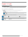
Chapter 12: Audio
51
12.1 Audio Mixer Configuration
53
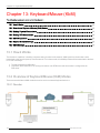
Chapter 13: Keyboard/Mouse (KbM)
13.1 How it Works
53
13.2 Overview of Keyboard/Mouse (KbM) Modes
53
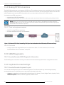
13.3 Making Physical Connections
54
13.4 Making RFB Connections
55
13.5 KB/M Diagnostics
55
13.6 Keyboard Locale Settings
55
13.7 KB/M Settings
56
57
Chapter 14: Administration
14.1 Administration
57
14.2 Management Settings
58
Appendix I: Supported Encoding/Decoding Resolutions
61
Appendix II: Making a Simple Connection Between an NGS-D200 Encoder and Decoder
63
II.1 Prerequisites
63
II.2 Encoder Setup
63
II.3 Decoder (client) Setup
63
II.4 Get Information about the Connection
64
K5903085
vi
Appendix III: Stereo Emitter Cable Specifications
65
Appendix IV: Required Settings to Use KbM in 4.x Collaboration Suite
67
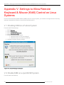
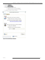
Appendix V: Settings to Allow Remote Keyboard & Mouse (KbM) Control on Linux Systems
69
V.1 Enabling KbM on a Fedora System
69
V.2 Enable KbM on a openSUSE System
69
Appendix VI: RFB Keyboard ASCII Guide
71
Appendix VII: Safety and Compliance Statements
73
VII.1 Compliance Statements
73
VII.2 General Considerations
74
VII.3 Important safety instructions
74
77
Appendix VIII: Environmental Statements
VIII.1 Disposal of the Product (Waste Electrical and Electronic Equipment)
77
VIII.2 Turkey RoHS compliance
77
VIII.3 Chinese Mainland RoHS
77
79
Appendix IX: BARCO, INC. END USER LICENSE AGREEMENT
vii
NGS-D200 User Guide
Chapter 1: How to Use this Manual
Chapter 1: How to Use this Manual
This user guide is for advanced configuration of the NGS-D200.
The NGS-D200 can be integrated into several operational workflows, satisfying a variety of AV streaming and collaboration
cases:
l
l
l
DVI-input node for the TransForm-N solution
l See the document "Installation and Configuration of TransForm N (R591408_00_Installation.pdf)
Replacement for the V2D XP line of encoders for users of the 4.x Barco Collaboration Suite. When used with the 4.x
Collaboration Suite, the NGS-D200 enables recording and playback of DVI sources
l See the document "4.x Admin UI Setup Guide (922-10060)"
Standalone unit for simple point-to-point sharing of video, audio, and keyboard/mouse
l For more information, see "Modes of Operation" on page 8
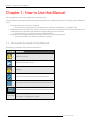
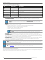
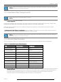
1.1 Conventions Used in this Manual
The following conventions may be used in this manual:
Convention Description
Electrical warning
Reference the user manual
Warning
Tip: gives extra advice about the described subject
Note: gives extra information about the described subject
Blue box
with text
Additional detailed information about the described subject
Pointer to the highlighted topic/item
Green Italics
E.g. Menu > Configuration > Option 1
1
NGS-D200 User Guide
Chapter 2: Product Overview
Chapter 2: Product Overview
The following topics are covered in this chapter:
2.1 NGS-D200 Features
3
2.2 NGS-D200 Summary
3
2.3 Physical Specifications
3
2.4 Front Panel Overview
4
2.5 Rear Panel Overview
5
2.6 Video Connection and Sync Specifications
6
2.7 Audio Connection Specifications
7
2.8 Device Defaults
8
2.9 Modes of Operation
8
2.1 NGS-D200 Features
l
l
l
l
l
l
l
l
On-the-fly digital compression and transmission
Encoder/decoder functionality in a single unit
Low end-to-end latency
Complete remote desktop sharing with remote USB keyboard and mouse(KbM) support
Redundant LAN
Passive video loop through
Dual Link resolution support (NGS-D200 Pro & NGS-D200 Pro 3D only)
3D stereoscopic graphics support (NGS-D200 Pro 3D only)
2.2 NGS-D200 Summary
Barco's NGS-D200 encoders (Tx)/decoders (Rx) enable seamless, point-to-point video, stereoscopic graphics and audio
distribution, plus keyboard/mouse control all with low latency. They ensure high quality collaborative experience in any
network and for any bandwidth allocation. Multi-site collaboration, simulation, training, testing and application sharing are
readily provided to small and large enterprises with unmatched visual fidelity.
The NGS-D200 leverages the power of the Barco's V2D (Video-to-data) codec. The Video-to-Data (V2D) codec is
optimized for collaboration and transmitting ultra HD computer graphics and data across networks. V2D is architected for
very high image quality, accurate color representation and sharp resolution of details and fine lines.
2.3 Physical Specifications
Table 2-1: NGS-D200 Physical Specifications
Size
3
H: 1.62" (41.15 mm), W: 4.8" (121.92 mm), D: 6" (152.44 mm)
NGS-D200 User Guide
Chapter 2: Product Overview
Weight
3.6 lbs. (1.6 kg)
Power
110/220 V AC, 60/50 Hz, 40 W, external, auto switchable
Operating Temperature Range 0-40o C
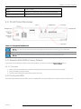
2.4 Front Panel Overview
Figure 2-1: Front panel of the NGS-D200
NOTE: The included SD card must always be plugged into the slot before powering up the NGS-D200.
NOTE: Make sure to properly shutdown and power off the unit before removing the SD card.
2.4.1 Reset the NGS-D200 to Factory Defaults
If you need to revert the device back to the factory defaults, you can do so with the Factory Reset button.
2.4.1.1 Procedure
1. Insert a pin into the small hole on the front panel grill (nine slots from the left-hand side of the grill)
2. Press the button for eight seconds
3. The front panel LEDs will flash and the system will reset
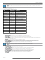
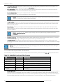
2.4.2 Front panel LEDs
The NGS-D200 features has two LEDs on the front panel that are used to identify the connection status of the device.
K5903085
4
Chapter 2: Product Overview
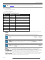
Table 2-2: Front Panel LED overview
LED
Legend:
The device is not configured as an encoder
Encoder
The device is configured as an encoder. If blinking, the encoder is connected to a decoder and
streaming video
The device is not configured as a decoder
Decoder
Passive loopback video is available (power provided from a USB or DVI connection)
The device is configured as a decoder. If blinking, the decoder is connected to an encoder and
receiving video
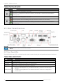
2.5 Rear Panel Overview
NOTE: End-to-end sync is not currently available.
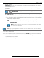
2.5.1 Rear Panel LEDs
The NGS-D200 has two LEDs on the back panel that can be used to identify the configuration and status of the device:
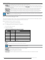
Table 2-3: Video In Indicator Overview
Color
Status
Off
No video detected
Solid Red
Video signal is detected, but a valid LUT is not detected
Solid Green
Video signal is detected and a valid LUT is detected
l
Blinking Green
5
l
Encoder: Video signal and LUT are detected and valid. The device is streaming to a
decoder
Decoder: Video signal and LUT are detected and valid. The device is configured in
"Local" mode
NGS-D200 User Guide
Chapter 2: Product Overview
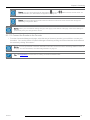
Table 2-4: Video Out Indicator Overview
Color
Status
Off
No monitor detected
Solid Red
Monitor is detected, but the NGS-D200 is unable to read its EDID
Blinking
Red
Monitor is detected, but the NGS-D200 is unable to display the video because the output signal is
unsupported by the monitor
Solid Green
Monitor is detected, and the video output is supported by the monitor
Blinking
Green
Decoder: Video is being decoded and is being displayed on the connected monitor
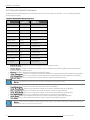
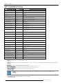
2.6 Video Connection and Sync Specifications
l
The NGS-D200 supports video input configured as either encoder or decoder.
K5903085
6
Chapter 2: Product Overview
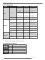
Table 2-5: Video Specifications
Function:
NGS-D200 Lite
NGS-D200 Pro
NGS-D200 Pro 3D
Digital: 800 x 600
to 1920 x 1200
Digital: 800 x 600
to 2560 x 1600
Digital: 800 x 600 to
2560 x 1600
Max pixel clock
rate of 165 MHz
Max pixel clock
rate of 330 MHz
Max pixel clock rate
of 330 MHz
Analog: 800 x 600
to 1920 x 1200
Analog: 800 x 600 Analog: 800 x 600 to
to 1920 x 1200
1920 x 1200
Max pixel clock
rate of 170 MHz
Max pixel clock
rate of 170 MHz
Max pixel clock rate
of 170 MHz
Refresh rate
Up to 120 Hz
Up to 120 Hz
Up to 120 Hz
Stereo
No
No
TTL stereo out via
3.5 mm-to-RCA
cable
Connectors
Single-link DVI-I
(Analog and
Digital)
Dual-link DVI-I
(Analog and
Digital)
Dual-link DVI-I
(Analog and Digital)
Minimum/maximum Analog: 0.5V to
levels
1.0V p-p
Analog: 0.5V to
1.0V p-p
Analog: 0.5V to 1.0V
p-p
Impedance
Analog: 75 Ω
Analog: 75 Ω
Analog: 75 Ω
Maximum DC
offset
4.0V
4.0V
4.0V
Stereo
No
No
TTL stereo out via
3.5 mm-to-RCA
cable
Connectors
Single-link DVI-D
(Digital)
Dual-link DVI-D
(Digital)
Dual-link DVI-D ( Digital)
Resolution
Video
Video Input
Video Output
2.7 Audio Connection Specifications
Table 2-6: Audio Connection Specifications
Type
Audio Input
Stereo (two-channel), unbalanced
Connectors 3.5 mm stereo jack, 3.5 mm mic
Impedance
3 kΩ, DC coupled
Type
Stereo (two-channel), unbalanced
Audio Output Connectors 3.5 mm stereo jack, 3.5 mm headphone
Impedance
7
500 Ω, AC coupled
NGS-D200 User Guide
Chapter 2: Product Overview
2.8 Device Defaults
All systems come with the following network configuration:
l
l
l
l
l
Multicast: Yes
Enabled: Yes
Primary: Yes
DHCP: Yes
MTU Size: 1500 bytes
NOTE: For more information, see "Network Configuration" on page 25
2.9 Modes of Operation
The system has two unique operating modes:
l
Standalone Mode - Each device must be individually configured and managed
NOTE: TransForm N users will operate the device in this mode.
l
Managed Mode (Barco Collaboration Suite) - Each device is centrally managed by the Barco Management Server
The unit must be set to operate in one of these modes. For more information, see "Standalone Mode" on page 58
2.9.1 Managed Mode
In Managed Mode, the device is used as part of networked, centrally managed, collaboration solution under the control of
the 4.x Barco Management Server. Bandwidth consumption can be dynamically provisioned in Managed mode.
If using Managed Mode, simply connect the unit to your network. If Auto Registration is enabled on the Management
Server, the NGS-D200 will be automatically registered and discovered. You can configure advanced settings centrally from
the Admin UI or use the Web UI, as described later in this document. Please see the 4.x Admin UI Setup Guide for more.
l
The device is part of a centrally managed collaboration solution that enables flexible stream routing, synchronous
recording, advanced policy management and more
l
4.x Collaboration Suite users, select this mode.
2.9.2 Standalone Mode
The device is used for simple point-to-point connections enabling sharing of visually lossless video and graphics, audio,
and ultra-low latency keyboard/mouse control over IP. In Standalone Mode, the decoder is setup to connect to the encoder
without the help of a management system.
If using the NGS-D200 as a Transform-N DVI input node, then use the device in Standalone Mode. Please see "Installation
and Configuration of TransForm N" for more on using the NGS-200 as part of the TransForm N environment
2.9.2.1 Standalone Mode Requirements
l
Both the encoders and decoders involved must:
o Have the appropriate network settings configured
o Have Standalone Mode enabled via the "Standalone Mode" page. For more information, see "Standalone
Mode" on page 58
K5903085
8
Chapter 2: Product Overview
l
Decoders:
o
o
9
Establish connections with the encoder (via Connection Manager Table)
For more information, see "Connection Manager Table" on page 35
NGS-D200 User Guide
Chapter 3: Unpacking the System
Chapter 3: Unpacking the System
The following topics are covered in this chapter:
3.1 What’s in the Box?
11
3.2 Unpacking the System
12
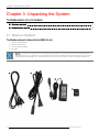
3.1 What’s in the Box?
The following equipment is shipped with the NGS-D200 unit:
1.
2.
3.
4.
Power cord for Europe
Power cord for USA
12 V DC power supply
SD card*
NOTE: *The SD card contains all necessary licensing information. If you have purchased the NGS-D200 Pro or
NGS-D200 Pro 3D, you will receive an additional SD card that will enable additional functionality beyond what is
supported by the NGS-D200 Lite. The NGS-D200 Pro 3D also comes with the 3D stereo kit (part # C9826147).
11
NGS-D200 User Guide
Chapter 3: Unpacking the System
Figure 3-1: NGS-200 accessories
3.1.1 NGS-D200 Pro 3D
The NGS-D200 Pro 3D also includes the 3D stereo kit (part # C9826147).
Figure 3-2: 3D Stereo Kit
3.1.2 Included documentation:
l
Hardcopy of the NGS-D200 Quick Start Guide (K5903053-00)
TIP: You can access the Quick Start Guide and NGS-D200 HW Guide through the Web UI.
3.2 Unpacking the System
3.2.1 Unpacking the unit
You should unpack and check the pieces of the NGS-D200 unit as soon as the system arrives.
3.2.2 Procedure
1.
2.
3.
4.
5.
Carefully open the box
Clear a space large enough for the NGS-D200 unit
Remove the NGS-D200 unit and set it on a cleared, flat surface for inspection
Check the chassis for any damage that may have occurred in shipping
Remove the accompanying accessories and check to see that everything is present
NOTE: If any accessories are missing or damaged, contact Customer Support for an immediate replacement.
NOTE: Do not place any weight on top of the unit. It is not designed to support weight and internal components can
be damaged if objects are placed on top of the NGS-D200 unit.
K5903085
12
Chapter 4: Installation and Connections
Chapter 4: Installation and Connections
The following topics are covered in this chapter:
4.1 Mounting the NGS-D200
13
4.2 Installation Diagram
13
4.3 Overview of Encoder/Decoder Dataflow
15
4.4 Connections for 3D/Stereoscopic Video
17
4.1 Mounting the NGS-D200
The NGS-D200 is designed to function as a desktop model. It is equipped with rubber feet to prevent scratching the surface
it is placed on. Additionally, two units can be mounted within a 1U rack space using the NGS-D200 rack mount kit (part
number C9826136 - not included).
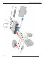
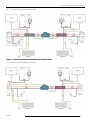
4.2 Installation Diagram
The NGS-D200 should be installed according to the following diagram.
13
NGS-D200 User Guide
Chapter 4: Installation and Connections
K5903085
14
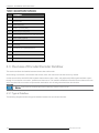
Chapter 4: Installation and Connections
Table 4-1: Encoder/Decoder Configuration
Description
1
Power Adaptor
2
Primary LAN
3
Redundant LAN
4
Audio In (3.5 mm jack)
5
Audio Out (3.5 mm jack)
6
DVI-I In (DVI-D to DVI-D or VGA to DVI-A)
7
HOST USB (Type B)
8
3D
9
DVI-D Out
10-13 USB Slots for Keyboard/Mouse
14
Mic In
15
Headphone Out
16
SD Card
4.3 Overview of Encoder/Decoder Dataflow
This section outlines the dataflow between the encoder and decoder.
After making a connection, the decoder side will see, hear, and control encoder-side source by default.
On the encoder side, the NGS-D200 loopback feature allows video, audio, and peripheral (USB) signals and data to pass
through for connection to a monitor, speakers and the source. This enables collaboration between the two sites as the user
at the encoder side can continue to operate their workstation as it is being shared with the decoder side.
NOTE: Video,audio and USB loopback are enabled by default on the encoder.
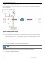
4.3.1 Typical Dataflow
The following diagrams outline the typical dataflow between an encoder and decoder.
15
NGS-D200 User Guide
Chapter 4: Installation and Connections
4.3.1.1 Encoder to Hardware Decoder
Figure 4-1: Typical dataflow between the encoder and hardware decoder
4.3.1.2 Encoder to Software Decoder
K5903085
16
Chapter 4: Installation and Connections
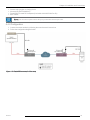
4.3.2 Decoder Local Mode Dataflow
For workflow flexibility, the decoder can be operated in "Local" mode to enable users to operate the workstation (local
source PC) at their desk.
Figure 4-2: The decoder operating in Local Mode
4.3.2.1 Setting the Decoder to Local Mode
Video, audio and keyboard/mouse mode must be set to "Local" mode to pass the respective input back to the source.
1. Video - Set the video to Local mode. For more information, see "Decoder Input Video Parameters" on page 45
2. Audio - Ensure the decoder audio mixer is appropriately configured. For more information, see "Audio Mixer
Configuration" on page 51
3. Keyboard/Mouse - Set the keyboard/mouse mode to "Local" mode. For more information, see "Decoder
Keyboard/Mouse Parameters" on page 56
4.4 Connections for 3D/Stereoscopic Video
NOTE: 3D/Stereoscopic video is only supported on the NGS-D200 Pro 3D. For information on upgrading to the Pro
3D, please contact Barco Sales.
This outlines a simple setup in which a single stereo source will be transmitted to the remote side.
4.4.1 Tools and equipment required
l
l
17
3D-visualization engine or other stereo video generating device
Stereo emitter (with power cords)
NGS-D200 User Guide
Chapter 4: Installation and Connections
l
l
l
l
Stereoscopic goggles or viewing device
3d stereo kit (part # C9826147)
Female BNC-to-male RCA adapters (2 included with NGS-D200 Pro 3D)
BNC cables
NOTE: The encoder requires active L/R sync input to detect stereoscopic video.
4.4.2 Configuration
1. Connect the stereo emitter by following the manufacturer’s instructions
2. Follow the configuration diagram below:
Figure 4-3: Simple 3D/stereoscopic video setup
K5903085
18
Chapter 5: Discovering the NGS-D200 and Accessing the Web UI
Chapter 5: Discovering the NGS-D200 and
Accessing the Web UI
This chapter discusses how to discover the NGS-D200 on your network, and how to access the Web UI to configure
device settings.
5.1 Powering on the NGS-D200
Now that the unit is connected, it is ready to be powered up.
5.1.1 Tools and equipment required
l
Power cord
5.1.2 Procedure
1. Plug one end of the power cord into the unit and the other end into a wall electrical outlet (100-240 V 50/60 Hz)
2. Ensure that the included SD card is properly inserted into the slot
3. Power on the unit via the power switch
NOTE: If the front panel LEDs fail to illuminate, a hardware failure has occurred. Please contact Customer Support.
5.2 Locate the Device
It is recommended to work with your deployment's IT department to appropriately configure and provision your network
before installing the unit. By default, the device is configured to use DHCP.
You can use the Barco Device Discovery Tool to locate devices on your local network segment (VLAN) and determine their
IP addresses.
5.2.1 Procedure
1. Download the Barco Device Discovery Tool:
http://www.barco.com/networktools
2. Follow the instructions below:
19
NGS-D200 User Guide
Chapter 5: Discovering the NGS-D200 and Accessing the Web UI
TIP: The serial number can be found on the back of the device and can be scanned using a Datamatrix code
reader.
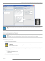
5.3 Configuration Wizard
NOTE: You will only be required to use the configuration wizard the first time the device is used or reverted to
factory defaults. You can use the Reset button on the front panel to revert the device to factory defaults.
5.3.1 What you'll need
l
A new device name and password
WARNING: Make sure to document the configured device name and password. You will have to revert the
system to factory defaults if this is lost or forgotten. For more information, see "Reset the NGS-D200 to
Factory Defaults" on page 4
l
l
l
l
Management Server IP/DNS name (if using the device in Managed Mode as part of the 4.x Collaboration Suite)
NTP Server IP/DNS name
If not using DHCP:
o IP address/DNS name
o gateway IP address/DNS name
o subnet mask
The multicast streaming address (optional)
K5903085
20
Chapter 5: Discovering the NGS-D200 and Accessing the Web UI
NOTE: If setting up encoder for streaming using Multicast mode, make sure that no two enocders have the
same mutlicast address.
This can be achieved by either using Standalone mode and setting a unique mutlicast address on each
encoder. OR,
Using managed mode, and setting up a pool of multicast addresses on Management Server - the
management server will assign unique multicast IP address to different encoders
l
l
l
The keyboard locale: See Keyboard Locale
Your choice of how the device will operate: encoder or decoder
If configuring the system as an encoder, you will be prompted to select the source type:
o Remote Desktop Interaction - optimized for capturing computer desktop screens
o High Resolution Graphics - optimized for highest image quality
o Full Motion Video - optimized for high frame rate
o Custom - create your own custom connection profile
NOTE: Once you have finished with the wizard, you will be taken to the Web UI.
NOTE: You can return to the wizard and change settings again from "Quick Setup" on the left navigation panel on
Web UI
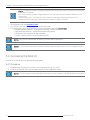
5.4 Accessing the Web UI
The Web UI is used for device configuration and operation.
5.4.1 Procedure
1. Navigate to the IP address of the device from a web browser (e.g. 10.1.5.50)
2. At the top of the page, enter the credentials created via the configuration wizard
NOTE: You can change the login credentials if necessary. For more information, see "Admin Account" on page 58
21
NGS-D200 User Guide
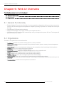
Chapter 6: Web UI Overview
Chapter 6: Web UI Overview
The following topics are covered in this chapter:
6.1 General Functionality
23
6.2 Organization
23
6.1 General Functionality
l
l
l
l
Expand/Collapse: Every section of the Web UI can be expanded or collapsed by clicking on the arrow next to the
section. Also, the entire page can be expanded or collapsed by clicking "Expand All" or "Collapse All" at the top of
the page
Page Refresh (F5): Refreshes the web page
Apply/Cancel Changes: Click "Apply" to make your changes take effect
Save Settings: Click "Save Settings" to permanently save you changes to the system SD card. The changes will
persist across device reboots
6.2 Organization
The Web UI is organized into several subsections:
l
l
l
l
l
l
l
l
l
l
l
l
23
Dashboard: provides an overview of the system info, status, and health.
System Information: provides an overview of key software, firmware, system, memory, time and temperature
information
Quick Setup: allows you to change basic settings thru the configuration wizard used during initial installation
Network: allows you to set the device network settings
Streaming: allows you configure streaming settings
Encoding/Decoding: allows you configure settings specific to the encoder/decoder
Video: enables you to configure specific video input and output settings
Audio: enables you to configure specific audio input and output settings
Keyboard/Mouse: allows you to configure keyboard and mouse settings
Administration: allows you to configure device management and administration settings
Discovery: shows other devices on your network. This is helpful for finding other clients and servers that you can
connect to
Documentation: provides links to the product documentation
NGS-D200 User Guide
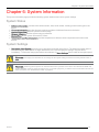
Chapter 6: System Information
Chapter 6: System Information
The System Information page provides the following system status and access to system settings
System Status
l
l
l
l
l
l
Software Information: provides build version number, date, serial number, model type and license type for the
device.
Firmware Information: provides firmware versions and dates of different firmware on the device.
System Information: provides uptime and load average.
Memory Utilization: provides system memory utilization
System Time: shows system time and NTP status
Temperature and Fan Information: provides temperature of different critical components and zones on the
devices
System Settings
l
Fan Speed of the System: provides way to change the fan speed on the Device. The default fan speed option is
set to Auto (High). Other options are High, Medium and Low. After changing the settings, they take effect
immediately. To make the change persistent across reboots, hit Save Settings: button under left navigation panel
WARNING: It is highly recommended to not change the fan speed setting and leave it at factory default value of
Auto.
WARNING: Reducing the fan speed can adverse effect of the operation of the device and will reduce MTBF and
product reliability. If the fan speed is reduced (e.g. for acoustic purposes,), it shall be done at customers own risk.For
more information, see "Authorization Table" on page 33
K5903085
24
Chapter 7: Network Configuration
Chapter 7: Network Configuration
Network Configuration allows you to set the device network settings as well as get real-time network statistics.
The following topics are covered in this chapter:
7.1 Network Statistics
25
7.2 Network Settings
25
7.1 Network Statistics
7.1.1 Interface
The Interface section gives real-time information about the device network interface
7.1.2 Routing
The Routing section gives real-time information about device static routes
7.2 Network Settings
7.2.1 Network Interface (IP Address Configuration)
You may want to reconfigure the default network settings of the device:
l
DHCP: Enables DHCP on the device
NOTE: Ensure DHCP is enabled if you wish to use the Device Discovery feature in the 4.x Collaboration
Suite.
l
l
l
MTU Size: Specifies the maximum transmission unit (MTU) size (in bytes). The default size is 1500.
IP Address: If not using DHCP, specifies the statics IP address of the device
Netmask: Specifies the interface netmask
NOTE: When you have finished making changes, click "Apply" at the bottom of the page. Click "Save Settings" to
permanently save your changes to the device.
7.2.2 Domain Name Service (DNS) Client
You can specify the DNS server and the device host name.
7.2.2.1 Notes
l
l
25
You must have preconfigured your DNS server
If using the device in Managed mode, DNS must already be configured on the Management Server. See the 4.x
Admin UI Setup Guide
NGS-D200 User Guide
Chapter 7: Network Configuration
l
Host name: Enter the host name for the device (e.g. my_system)
l
Local Domain Name: Enter the local domain name for you network
NOTE: If using the device in Managed mode, enter the domain name of the Management Server (e.g
barco.com)
l
DNS Server IP Address: Enter the IP address of your deployment's DNS server
NOTE: When you have finished making changes, click "Apply" at the bottom of the page. Click "Save Settings" to
permanently save your changes to the device.
7.2.3 NTP Client Configuration
You can configure the device as a client to an NTP server.
l
l
Enable: Enables the system to be an NTP Client to the specified server
NTP Server: Enter the IP address of the NTP server
NOTE: When you have finished making changes, click "Apply" at the bottom of the page. Click "Save Settings" to
permanently save your changes to the device.
7.2.4 Static Routes
You can configure static routes for the device if you need to communicate with devices outside of your LAN (e.g. 10.1.5.x).
1. Click "Add" to add a new route
2. Configure the following:
l Destination: Specify the remote LAN network address
l Netmask: Specify the netmask of the network address (e.g. 255.255.0.0)
l Gateway: Specify the IP address of your network gateway
NOTE: When you have finished making changes, click "Apply" at the bottom of the page. Click "Save Settings" to
permanently save your changes to the device.
K5903085
26
Chapter 8: Streaming
Chapter 8: Streaming
The Streaming menu is used to define audio/video, multicast, and control port ranges, enable or disable reverse audio, as
well make and break Standalone connections between encoder and decoder.
The following topics are covered in this chapter:
8.1 Streaming Statistics
27
8.2 Streaming Settings
28
8.1 Streaming Statistics
the Streaming Statistics page gives real-time information about the status of a connection. After making a connection, you
can use this page to get detailed information from the perspective of the encoder or decoder.
8.1.1 Connection Information (Encoder)
l
Client: Displays the IP address of the currently connected client. For multicast connections, the system will display
the IP address of the first client that connected
Status: Displays the connection status of the encoder`
LUT: Displays the name field of the currently matching LUT entry
l
Max BW: Displays the configured maximum bandwidth allowed to connected clients
l
l
NOTE: Max BW should not normally change unless a currently connected client disconnects and a new
client joins matching a different Authorization Entry. It may also change if you manually change the Max BW
via the user interface (e.g. from a separate SSH or console session).
l
l
l
l
l
l
l
l
l
l
l
l
l
Interface:
o Analog HV: Indicates if the input video is RGB (H sync and V sync detected)
o Analog SOG: Indicates if the input video is RGB with Sync on Green (SoG) or composite sync
o DVI: Indicates if the input video is DVI
o “????”: Indicates that no input video is detected
Video Bytes: Displays the number of bytes currently consumed by video data
Audio Bytes: Displays the number of bytes currently consumed by audio data
Horiz. Freq:Displays the refresh rate of the horizontal video signal from the DVI inputs (Hz)
Vert. Freq: Displays the refresh rate of the vertical video signal from the DVI iput (Hz)
Horizontal Lines: Indicates the total number of horizontal lines observed in the connected video signal
Stereo: Indicates if a stereo video signal is detected
Frames: Displays the total number of frames processed so far
Slices: Displays the total number of slices processed so far
Frame Rate: Indicates the number of frames processed per second
Slice Rate: Indicates the number of slices processed per second
Local Video Output: Indicates if the encoder is displaying its encoded video source out via the DVI-D OUT port
Reverse Audio Bytes: Displays the number of bytes currently consumed by reverse (bidirectional) audio
8.1.2 Streaming Statistics (Decoder)
l
l
27
Server: Displays the IP address of the currently connected encoder server
Status: Displays the connection status of the decoder
NGS-D200 User Guide
Chapter 8: Streaming
l
Remote LUT: Displays the name field of the LUT used to process video on the V2D encoder
l
Display LUT: The name field of the LUT the decoder is using to override the Remote LUT if Override is enabled
NOTE: The 'Display LUT' field will show "????" if decoder override is disabled.
l
l
l
l
l
l
l
l
l
l
l
l
l
l
l
l
l
Current Bytes: Displays the total amount of bytes the decoder is currently using to decode
Genlock Status: Indicates if a stereo video signal is detected
Video Bytes: Displays the number of video bytes the decoder has so far received from the connected encoder
Video Packets: Displays the total number of UDP video packets so far received from the connected encoder
Video Lost: Displays the number of video packets lost so far from the connected encoder
Video Order: Displays the number of out of order video packets received so far from the connected encoder
Video Dropped: Displays the number of video packets dropped so far from the connected encoder
Video Frames: Displays the number of video frames so far processed by the decoder
Video Slices: Displays the number of video slices so far processed by the decoder
Audio Bytes: Displays the number of audio bytes the decoder has so far received from the connected encoder
Audio Packets: Displays the total number of UDP audio packets so far received from the connected encoder
Audio Lost: Displays the number of audio packets lost so far from the connected encoder
Audio Order: Displays the number of out of order audio packets received so far from the connected encoder
Rev Audio Bytes: Displays the number of reverse audio bytes the decoder has so far received from the connected
encoder
Audio Dropped: Displays the number of audio packets dropped so far from the connected encoder
Queue Drops: Displays the number of queued packets dropped so far from the connected encoder
Video Output: Indicates if the decoder is outputting video
8.2 Streaming Settings
8.2.1 Connection Profile
The Connection Profile defines the quality and encoding parameters of the device.
WARNING: When you use a Connection Profile, any decoder on your network will be able to connect to the
encoder. If you would like to restrict access to the encoder, make sure to enable and configure the Authorization
Table option. For more information, see "Authorization Table" on page 33
K5903085
28
Chapter 8: Streaming
Table 8-1: Default/Valid Connection Profile Settings
Field
Default Value
Valid Entries
Use Authorization
Table
No
No, Yes
Profile
Remote Desktop
Interaction
Remote Desktop Interaction, High Resolution Graphics, Full Motion
Video, Custom
Max Bandwidth
10.0 M
N/A
Low Compression
6
0-10
High Compression
6
0-10
l
Use Authorization Table: Enable this if you wish to use an Authorization Table. This protects unwanted access to
your encoder by authorizing only clients from specific IP addresses or networks to connect to the encoder.
NOTE: After enabling this field and clicking "Apply", the Authorization Table section of the page will
appear.
l
Profile: Select the appropriate Connection Profile
o Remote Desktop Interaction - optimized for capturing computer desktop screens
o High Resolution Graphics - optimized for highest image quality
o Full Motion Video - optimized for high frame rate
o
Custom - create your own custom profile
NOTE: You wlll only need to configure the following settings if you select a "Custom" Profile
l
l
l
Bandwidth: Sets the bandwidth that the encoder will allocate for the decoder (client) to consume (Mbps)
Low Compression: Sets the compression level applied to portions of the input video where the image is static or
has very little motion (e.g. mouse cursor moving). Values between 0-7 are recommended for the best visual results.
Higher values (8-10) are recommended for networks with bandwidth constraints
High Compression: Sets the compression level applied to portions of the input video where the image is detected
to be dynamic. Values between 0-7 are recommended for the best visual results Higher values (8-10) are
recommended for networks with bandwidth constraints
NOTE: When you have finished making changes, click "Apply" at the bottom of the page. Click "Save Settings" to
permanently save your changes to the device.
TIP: See Appendix II for additional instructions on making connections between units.
8.2.2 Encoder Splash Parameters
The encoder will display a splash screen when there is no local input video detected. You can configure the settings of the
splash screen or force the splash screen to always display with this menu.
29
NGS-D200 User Guide
Chapter 8: Streaming
NOTE: You will see the encoder splash screen if you connect an idle encoder to an decoder on the decoder
output.
Table 8-2: Default/Valid Splash Parameters
Field
Default Value Valid Entries
Splash Screen
Blue Screen
Blue Screen, Grid Lines
Splash B/W
1.00 M
0-supported bandwidth of device
Enable Splash
Yes
Yes, No
Stereo?
No
Yes, No
Horiz. Resolution
1280
0-size of monitor (pixels)
Vert. Resolution
1024
0-size of monitor (pixels)
Refresh Rate
60.02
1-500 (Hz)
Pixel Clock Rate
108.00
20-330 (MHz)
Horiz. Front Porch 48
0-1000 (pixels)
Vert. Front Porch
0-1000 (lines)
1
Horiz. Back Porch 248
0-1000 (pixels)
Vert. Back Porch
38
0-1000 (lines)
Horiz. Synch
112
0-1000 (pixels)
Vert. Synch
3
0-1000 (lines)
l
l
l
l
l
l
l
Splash Screen: Allows you to selects the appearance of the splash screen
Splash B/W: Allows you to adjust the bandwidth consumed by the splash screen
Enable Splash: Enables or disables the splash screen. If disabled, you will see a blank screen instead of the
typical blue or grid splash screen
Stereo?: Enables the splash screen to be displayed in stereo
Horiz. Resolution: Allows you to adjust the horizontal resolution of the displayed encoder splash screen
Vert. Resolution : Allows you to adjust the vertical resolution of the displayed encoder splash screen
Refresh Rate: Enables you to adjust how often the splash screen will refresh itself
NOTE: The following parameters should only be adjusted by very advanced users.
l
l
l
l
l
l
l
Pixel Clock Rate: Adjusts the pixel clock of the video
Horiz. Front Porch: Allows you to adjust the number of columns of horizontal front porch
Vert. Front Porch: Allows you to adjust the number of lines of vertical front porch
Horiz. Back Porch: Allows you to adjust the number of columns of horizontal back porch
Vert. Back Porch: Allows you to adjust the number of lines of vertical back porch
Horiz. Sync: Allows you to adjust the number of columns of horizontal synchronization
Vert. Sync: Allows you to adjust the number of lines of vertical synchronization
K5903085
30
Chapter 8: Streaming
8.2.3 Decoder Splash Parameters
A splash screen will be displayed on the decoder when it is not connected to an encoder. You can modify the splash
screen using this page.
Table 8-3: Default/Valid Splash Parameters
Field
Default Value Valid Entries
Splash Screen
Grid Lines
Blue Screen, Grid Lines
Enable Splash
Yes
Yes, No
Stereo?
No
Yes, No
Horiz. Resolution
1280
0-size of monitor (pixels)
Vert. Resolution
1024
0-size of monitor (pixels)
Refresh Rate
60.02
1-500 (Hz)
Pixel Clock Rate
108.00
20-330 (MHz)
Horiz. Front Porch 48
0-1000 (pixels)
Vert. Front Porch
0-1000 (lines)
1
Horiz. Back Porch 248
0-1000 (pixels)
Vert. Back Porch
38
0-1000 (lines)
Horiz. Synch
112
0-1000 (pixels)
Vert. Synch
3
0-1000 (lines)
l
Splash Screen: Allows you to select the appearance of the splash screen
l
Enable Splash: Enables or disables the splash screen. If disabled, you will see a blank screen instead of the
typical blue or grid splash screen
Stereo?: Enables the splash screen to be displayed in stereo
Horiz. Resolution: Allows you to adjust the horizontal resolution of the displayed encoder splash screen (pixels)
Vert. Resolution : Allows you to adjust the vertical resolution of the displayed encoder splash screen (pixels)
Refresh Rate: Allows you to adjust how often the splash screen will refresh itself (ms)
l
l
l
l
NOTE: The following parameters should only be adjusted by very advanced users.
l
l
l
l
l
l
l
Pixel Clock Rate: Allows you to adjust the pixel clock of the video (MHz)
Horiz. Front Porch: Allows you to adjust the number of columns of horizontal front porch (pixels)
Vert. Front Porch: Allows you to adjust the number of lines of vertical front porch (lines)
Horiz. Back Porch: Allows you to adjust the number of columns of horizontal back porch (pixels)
Vert. Back Porch: Allows you to adjust the number of lines of vertical back porch (lines)
Horiz. Sync: Allows you to adjust the number of columns of horizontal synchronization (pixels)
Vert. Sync: Allows you to adjust the number of lines of vertical synchronization (lines)
NOTE: When you have finished making changes, click "Apply" at the bottom of the page. Click "Save Settings" to
permanently save your changes to the device.
31
NGS-D200 User Guide
Chapter 8: Streaming
8.2.4 Force Splash Screen (Encoder)
You can choose to always display the splash screen, even if the encoder is actively encoding video. This is helpful if you
are having trouble displaying a video source and need to ensure the problem is not related to a network connection to the
decoder.
l
l
Force Splash Screen: Check the box to enable splash mode
Splash Mode: After enabling the check box, click "Splash Mode" to force the encoder to display the splash screen
NOTE: When you have finished making changes, click "Apply" at the bottom of the page. Click "Save Settings" to
permanently save your changes to the device.
8.2.5 Encoder Control Port Range
If you need to adjust the default control ports range of a particular device, you can do so here.
l
Configure the following entries:
o Control Port Start
o Control Port End
NOTE: When you have finished making changes, click "Apply" at the bottom of the page. Click "Save Settings" to
permanently save your changes to the device.
8.2.6 Multicast Parameters
You can adjust the multicast parameters of each system including the multicast address range and TTL.
NOTE: By default, the system uses a mutlicast range of 226.1.1.1 - 226.1.1.50.
l
Configure the following fields:
o Multicast Address Start
o
Mutlicast Address End
NOTE: This field is not currently supported. Please specify the same address for the both Mutlicast
Address Start and Multicast Address End.
o
Multicast TTL (Time-to-live)
NOTE: When you have finished making changes, click "Apply" at the bottom of the page. Click "Save
Settings" to permanently save your changes to the device.
8.2.7 Reverse Audio
Reverse audio will send audio from a Standalone decoder to encoder, enabling two-way communication between the
locations.
8.2.7.1 Notes
l
l
Reverse Audio can only be used by devices in Standalone Mode.
Reverse Audio must be enabled on both ends of the connection (encoder or decoder) via the Streaming page
K5903085
32
Chapter 8: Streaming
l
You must specify the connection to use audio via the Connection Manager Table page.
8.2.7.2 Enabling Reverse Audio
l
Enable: check to enable reverse audio
NOTE: When you have finished making changes, click "Apply" at the bottom of the page. Click "Save Settings" to
permanently save your changes to the device.
NOTE: You can choose which audio input (Mic in
or Line In
information, see "Audio Mixer Configuration" on page 51
) will be used for reverse audio. For more
8.2.8 Audio/Video Ports Range
You can adjust the audio/video port ranges of the device if needed.
NOTE: The default A/V port range is 6060 - 6399.
l
l
For Standalone encoders: designate any open ports 6060 – 7000 (default range)
For Standalone decoders: designate any port range outside of the default range
NOTE: When you have finished making changes, click "Apply" at the bottom of the page. Click "Save Settings" to
permanently save your changes to the device.
8.2.9 Authorization Table
The Authorization Table provides protection against unwanted access to your encoder. You can authorize clients from
specific IP addresses or networks to connect to be able to connect to the encoder.
NOTE: You must select "Use Authorization Table" under the Connection Profile section of the page in order to
expose the Authorization Table section of the page.
NOTE: The Authorization Table only applies for Standalone Mode connections. For more information, see
"Standalone Mode" on page 58
Certain priorities apply when overlapping Authorization Tables entries are configured:
For example, assume there are two entries in the list:
1. IP Address: 10.1.0.0, Netmask: 255.255.0.0, Bandwith: 10M
2. IP Address: 10.1.5.50, Netmask: 255.255.255.255, Bandwidth: 10 M
The more specific entry (Entry #2) will be solely enforced.
Suppose a third entry is added to the list. Two entries are equally 'specific':
1. IP Address: 10.1.0.0, Netmask: 255.255.0.0, Bandwidth: 10M
2. IP Address: 10.1.5.50, Netmask: 255.255.255.255, Bandwidth: 10 M
3. IP Address: 10.1.5.50, Netmask: 255.255.255.255, Bandwidth: 20 M
Entry #2 will be solely enforced because it is higher in the list than Entry #3
33
NGS-D200 User Guide
Chapter 8: Streaming
TIP: See Appendix II for additional instructions on making connections between units.
8.2.10 Procedure
1. Click "Add" to add a new entry
2. Configure the following:
Table 8-4: Default/Valid Authorization Parameters
Field
Default Value Valid Entries
Host/Network IP
0.0.0.0
N/A
Netmask
0.0.0.0
N/A
Enable
Yes
Yes, No
Max Bandwidth
10 M
0- Maximum supported bandwidth of device
Low Compression
6
0-10
High Compression 6
0-10
Unicast?
Yes
Yes, No
Preemptible?
No
Yes, No
Int Multicast
Yes
Yes, No
Join Multicast
Yes
Yes, No
l
Network: Enter the IP address or domain name of the device or network you wish to authorize to connect to the
encoder
l
Netmask: Enter the netmask of the device or network you wish to authorize to connect to the encoder
TIP: To allow any decoder (client) to establish a connection with the encoder, set Network and Netmask to
0.0.0.0.
TIP: To authorize an entire network, enter the network IP address/domain name (e.g 10.1.5.0) into the
Network field and enter the network netmask (e.g. 255.255.255.0) into the Netmask field.
TIP: To authorize a specific decoder (client), enter its specific IP address/domain name into the Network
field and set the Netmask to 255.255.255.255.
l
l
l
l
Enable: Enables you to disable an entry without actually deleting it. When set to "No," the entry is ignored
Bandwidth: Allows you to cap the maximum bandwidth that a connected client can consume (Mbps)
Low Compression: Allows you to control the amount of compression applied to portions of the input video where
the image is static or has very little motion (e.g. mouse cursor moving). Values between 0-7 are recommended for
the best visual results. Higher values (8-10) are recommended for networks with bandwidth constraints
High Compression: Allows you to control the amount of compression applied to portions of the input video where
the image is detected to be dynamic. Values between 0-7 are recommended for the best visual results Higher
values (8-10) are recommended for networks with bandwidth constraints
K5903085
34
Chapter 8: Streaming
l
l
l
l
l
l
Unicast: Clients matching this rule are allowed to make unicast connections
Preemptible: Manages the number of active connections to the encoder. If another client is currently connected
and a second client attempts to connect to that encoder (when Preemptible is set to "Yes") the original client will be
preempted (disconnected)
Multicast Init.: Clients matching this rule are allowed to initiate a multicast session (does not imply participation)
Multicast Join: Clients matching this rule are allowed to participate (join) a preconfigured multicast session
Init Multicast: Clients matching this rule are allowed to initiate a multicast session (does not imply participation)
Join Multicast: Clients matching this rule are allowed to participate (join) a preconfigured multicast session
NOTE: When you have finished making changes, click "Apply" at the bottom of the page. Click "Save Settings" to
permanently save your changes to the device.
8.2.11 Connection Manager Table
The Connection Manager Table is used to connect an NGS-D200 decoder directly to an encoder. The decoder can switch
connections to different encoders by selecting different entries from this menu.
Before attempting to make a connection, ensure that:
l
Both devices are operating in Standalone Mode
8.2.11.1 Adding an Encoder (Server) to Connect to
1. Click "Add" to add a new entry
2. Configure the following:
Table 8-5: Default/Valid Connection Manager Parameters
Field
Default Value Valid Entries
Server
N/A
N/A
Port
6060
Valid port on the encoder
Bandwidth
10 M
0- maximum supported bandwidth of device
Multicast
No
Yes, No
Audio/Video Video
Video, Audio, Both
Bidirectional No
Yes, No
l
Server: Specify the IP address or host name of the encoder to connect to
l
Port: Specify the server port number on the encoder to connect to
NOTE: The default server port for any V2D encoder is 6060.
l
Bandwidth: Specify the desired bandwidth for the connection (Mbps)
Multicast: Choose to enable multicast connections
Audio/Video: Specify the supported connection(s)
l
Bidirectional: Choose to enable transmission of audio in the reverse manner, from decoder to encoder
l
l
35
NGS-D200 User Guide
Chapter 8: Streaming
NOTE: You can choose which audio input (Mic in
or Line In
more information, see "Audio Mixer Configuration" on page 51
) will be used for reverse audio. For
NOTE: Reverse (bidirectional) Audio must be enabled on both the encoder and decoder through the
Streaming Configuration Menu.
NOTE: When you have finished making changes, click "Apply" at the bottom of the page. Click "Save Settings" to
permanently save your changes to the device.
8.2.11.2 Connect the Encoder to the Decoder
l
From the Connection Manager main page, select the entry of the server (encoder) you would like to connect your
decoder to. You can also use the Connection Manager to break any existing connections between the decoder and
the encoder by clicking "Disconnect."
NOTE: You can get real-time connection information about the connection from the Streaming Statistics section of
the page. For more information, see "Streaming Statistics" on page 27
TIP: See Appendix II for instructions on making connections between units.
K5903085
36
Chapter 9: Encoding
Chapter 9: Encoding
The following topics are covered in this chapter:
37
9.1 Encoding Settings
The Encoding page is used to configure various encoder settings.
9.1 Encoding Settings
9.1.1 Encoder Connection Parameters
Once a connection is made, you can dynamically optimize the video quality by adjusting the connection parameters.
Table 9-1: Default/Valid Encoder Connection Parameters
Field
Default Value Valid Entries
Max Bandwidth
10.0 M
0- Maximum supported bandwidth of the device (Mbps)
Low Compression
6
0-10
High Compression 6
0-10
AV Option
Audio, Video, Both
Both
FrameRate Divider 1
1-256
Min Refresh
10
0-255 (Hz)
Max Refresh
30
0-255 (Hz)
Color Sampling
4:2:2
4:2:2, Static 4:4:4, Dynamic 4:4:4
Allow K/M Switch
No
Yes, No
K/M Idle Limit
5
3-30 (s)
l
Max Bandwidth: Enables you to specify the maximum bandwidth the connection can utilize (Mbps)
l
Frame Rate Divider: Allows you to specify the fraction of video frames the encoder processes
For example, if the input video has a refresh rate of 60, a value of 3 in this parameter will make the system process
at most 20 frames per second, so flow control will not be necessary as long as the maximum bandwidth is
sufficiently high to accommodate 20 frames per second
37
l
Low Compression: Allows you to control the amount of compression applied to portions of the input video where
the image is static or has very little motion (e.g. mouse cursor moving). Values between 0-7 are recommended for
the best visual results. Higher values (8-10) are recommended for networks with bandwidth constraints
l
High Compression: Allows you to control the amount of compression applied to portions of the input video where
the image is detected to be dynamic. Values between 0-7 are recommended for the best visual results. Higher
values (8-10) are recommended for networks with bandwidth constraints
l
Min/Max Refresh: The encoder continuously sends updated video information to connected clients. Only small
sections of the screen are sent for every video frame, and over a period of time, the whole screen is completely
NGS-D200 User Guide
Chapter 9: Encoding
refreshed. This mechanism compensates for lost packets on the network and allows the client to always be in sync
with the latest video data. The rate of these continuous updates can be configured using Min and Max Refresh
l
o
Min Refresh: Setting high values for Min Refresh gives better error resiliency on a lossy network at the cost
of higher bandwidth usage. Adjust this setting if you are losing packets and seeing latent video
o
Max Refresh: The encoder recognizes video transition from dynamic to static motion and can give a
momentary boost to the refresh rate to make the static image quickly appear at a higher quality. The Max
Refresh controls the rate of this faster refresh that continues until a whole screen of data is transmitted.
Increasing the Max Refresh will refresh the screen faster by generating a larger burst
Color Sampling :
o 4:2:2 - (Default) Standard color sampling
o Static 4:4:4 - Use this setting if you are looking at static images that require very accurate colors
o Dynamic 4:4:4 - Use this setting if you are looking at moving images that require very accurate colors
NOTE: It is recommended to use Static and Dynamic 4:4:4 sampling only if you have enough bandwidth
available. For best quality, set Min Refresh to a high value when using 4:4:4 color sampling.
l
l
Allow K/M Switch: Enable if you wish to allow multiple remote clients to control a PC (via keyboard & mouse) that
is connected to a multicast encoder. When using remote keyboard & mouse to control a host PC, KbM data is
transferred from the decoder to encoder to host PC on a first come, first serve basis. By default, the first client to
connect to the encoder will be the "controlling client." After a period of inactivity (K/M Idle Limit), other clients will
have the opportunity to become the controlling client
K/M Idle Limit: If Allow K/M Switch is enabled, this setting determines how long (seconds) the controlling client can
be idle before another client can contend to become the controlling client
NOTE: When you have finished making changes, click "Apply" at the bottom of the page. Click "Save Settings" to
permanently save your changes to the device.
9.1.2 Encoder Keyboard/Mouse Server Parameters
If necessary, you can configure the encoder to behave as an RFB client. For more information, see "Making
RFB Connections" on page 55
You will configure the encoder to connect to the host PC acting as a RFB server:
l
l
l
l
l
Enable: Enables the encoder (RFB client) to connect to the host PC (RFB server): Set to "Yes" or "No"
IP Address: Enter the IP address of the host PC
Password: If the host PC RFB server requires a password, enter it here
Port: Specifies the port to connect to on the host PC
XOffset: Specifies the X-coordinate in reference to the host PC that you want the system to reference as a starting
coordinate for KbM control
For example, if you are encoding the right-hand side of a PC that is configured in extended desktop mode with two
1600 x 1200 displays, you would enter "1600" for the XOffset entry
l
YOffset: Specifies the Y-coordinate in reference to the host PC that you want the system to reference as a starting
coordinate for KbM control
For example, if you are encoding the bottom side of a PC that is configured in vertical extended desktop mode with
two 1600 x 1200 displays, you would enter "1200" for the YOffset entry
K5903085
38
Chapter 9: Encoding
NOTE: When you have finished making changes, click "Apply" at the bottom of the page. Click "Save Settings" to
permanently save your changes to the device.
39
NGS-D200 User Guide
Chapter 10: Decoding Settings
Chapter 10: Decoding Settings
The following topics are covered in this chapter:
41
10.1 Decoding Settings
This menu is used to configure various decoder settings.
10.1 Decoding Settings
10.1.1 Display Parameters
Decoder Display Parameters is used to switch the decoder video mode from Local to Remote modes and is also used to
set the positioning of the video on the decoder and encoder sides.
Table 10-1: Default/Valid Decoder Display Parameters
Field
Default Value
Valid Entries
Video Source
Remote
Local, Remote
Override
Monitor
Monitor, None
Override Color
Blue
Blue, Yellow, Magenta, Cyan, Black, White, Gray, Red, Green
Horiz/Vert Position Location, Location Location, Offset
Horiz Location
Left
Left, Center, Right
Vert Location
Top
Top, Middle, Bottom
Horiz/Vert Offset
0, 0
0-horizontal (from left) or vertical (from top) pixels
l
Video Source: Allows you to switch output video from Local, Remote modes
l
Override: This menu allows you to define the scheme to render video on the decoder. You can choose to render
video in one of several ways:
o
Monitor: Video is rendered to fit the best supported resolution of the monitor
o
None: Video is rendered to match the resolution of the encoded video (at the encoder end)
l
Override Color: If the scheme you select to render your video creates a negative space boarder around your video,
you can select what color the negative space will be
l
Horz/Vert Position: Controls what scheme the system uses to offset the video
NOTE: When set to 'Location,' Horiz/Vert Location will be used to offset the video. When set to "Offset,"
Horiz/Vert Offset will be used to specify the offset (pixels).
l
l
l
41
Horiz Location: When Horiz Position is set to 'Location,' specifies the horizontal location of your video
Horiz Offset: When Horiz Position is set to 'Offset,' specifies the horizontal location of your video in relation to the
left edge of the display
Vert Location: When Vert Position is set to 'Location,' specifies the vertical location of your video
NGS-D200 User Guide
Chapter 10: Decoding Settings
l
Vert Offset: When Vert Position is set to 'Offset,' specifies the horizontal location of your video in relation to the top
edge of the display
NOTE: If the horizontal or vertical pixel offset is out of the range of your monitor, the system will
automatically adjust the video to fit your monitor.
NOTE: When you have finished making changes, click "Apply" at the bottom of the page. Click "Save Settings" to
permanently save your changes to the device.
K5903085
42
Chapter 11: Video
Chapter 11: Video
The Video menu is used to get real-time information regarding the device or monitor EDID as well as to configure the device
video settings.
The following topics are covered in this chapter:
11.1 Video Diagnostics
43
11.2 Video Settings
43
11.1 Video Diagnostics
11.1.1 EDID to Video Source
The EDID to Video Source section displays the EDID being presented to the connected source.
11.1.2 Monitor EDID
The Monitor EDID section gives real-time information about the EDID from the connected monitor.
11.2 Video Settings
11.2.1 Use Preferred Video Timings from Monitor
You can automatically synchronize the system EDID with that of the local monitor. The NGS-D200 will read the
EDID information from the monitor and use this to automatically create a video look up table to capture the input video.
l
Enable: check to enable
NOTE: When you have finished making changes, click "Apply" at the bottom of the page. Click "Save Settings" to
permanently save your changes to the device.
TIP: If you wish to connect a monitor to the NGS-D200 simply to get the EDID for image capture, then do the
following: from the Video section of the Web UI, you must first delete the “List of Preferred Timings in EDID to
Source” then select to “Use Preferred Video Timings from Monitor,” click “Apply,” click “Save Settings” and then
reboot the system. Note that the “List of Preferred Timings in EDID to Source” section of the page will only appear
when the “Use Preferred Video Timings from Monitor” setting is disabled.
11.2.2 Video Input Type
You can set the EDID video input for either digital or analog video.
l
43
EDID Video Input: Select "Digital" or "Analog"
NGS-D200 User Guide
Chapter 11: Video
NOTE: When you have finished making changes, click "Apply" at the bottom of the page. Click "Save Settings" to
permanently save your changes to the device.
11.2.3 Auto Detect Video Timings From DVI
NOTE: This option is used when DVI input is used.
l
Enable AutoLUT: check to enable
It makes the operation in DVI mode easier. User does not need to create look up tables (LUTs) manually for input video
timing detection. NGS-D200 can automatically create a video LUT from input video timings.
When this option is enabled, other LUTs created in the system are ignored for video detection and the auto created
LUT takes precedence.
If Use Preferred Video Timings from Monitor option is disabled, LUTs in the sytem can be used to announce specific
video timings over EDID to source connected at input (not a common case)
NOTE: When you have finished making changes, click "Apply" at the bottom of the page. Click "Save Settings" to
permanently save your changes to the device.
11.2.4 Encoder Video Parameters
Once a connection is made, you can dynamically optimize the video quality by adjusting the video parameters.
Table 11-1: Default/Valid Encoder Video Parameters
Field
Default Value
Valid Entries
Sampling Phase
0
-16-15
Local Video Output
Yes
Yes, No
Fine Noise Elim
16
1-2048
Course Noise Film
10
1-256
Horiz Position
0
-135-375 (px)
Vert Position
0
-25-50 (px)
LUT Change Pump Curr
Auto
Auto, 50, 100, 150, 250, 350,
500, 750, 1500 (µA)
Optimize Latency
No
Yes, No
I-Frame Interval
0
1-256 (ms)
l
Sampling Phase: (Analog Video Only) The sampling phase is adjusted to minimize noise of the video source that is
result of the source's hardware (video card, cables, etc.) and video resolution. Ideally, this field should be set to a
level that minimizes bandwidth usage. You can check the bandwidth usage from the Display Connection
Information Page to find a sampling phase that works best for your deployment
K5903085
44
Chapter 11: Video
l
l
l
Local Video Output: Projects the video source you are encoding locally without the need for a DVI splitter. The
local video output will be displayed through the DVI-D OUT port.
Fine Noise Elim: Allows you to adjust the higher order noise threshold below which two successive frames are
considered identical. It is not recommended to change this field
Course Noise Elim: Allows you to adjust the lower order noise threshold below which two successive frames are
considered identical. It is not recommended to change this field
NOTE: Setting both coarse and fine noise elimination to 1 means all successive frames will be considered
different, i.e. all slices in all frames will be transmitted.
l
Horiz Position: Allows you to adjust the horizontal position of the encoded video. Only adjust this field if the video
output is being cut off on the left and right sides and adjusting the horizontal position of the monitor on the Rx side
does not fix the problem
l
Vert Position: Allows you to adjust the vertical position of the encoded video. Only adjust this field if the video
output is being cut off on the top and bottom and adjusting the vertical position of the monitor on the Rx side does
not fix the problem
NOTE: Horiz/Vert Position always apply to analog video. They will also apply to digital video when
DVI Mode is set to "LUT."
l
l
Optimize Latency: This setting improves latency when small motions cannot be seen on the video (e.g. a mouse
cursor is not seen moving). Enabling this setting will increase your bandwidth usage
I-Frame Interval: This setting changes the time before a complete screen refresh occurs in milliseconds (ms).
Increasing this value will reduce the frame rate but increase your bandwidth usage. It is not recommended to change
this value
NOTE: When you have finished making changes, click "Apply" at the bottom of the page. Click "Save Settings" to
permanently save your changes to the device.
11.2.5 Decoder Input Video Parameters
You can change video parameters for the local input video on the decoder ( source from the DVI-I IN port) from this menu.
Table 11-2: Default/Valid Decoder Input Video Parameters
Field
Default Value Valid Entries
Sampling Phase
0
-16 - 15
Horiz Position
0
-135 - supported number of horizontal pixels of the monitor
Vert Position
0
-25 - supported number of vertical pixels of the monitor
LUT Charge Pump Curr Auto
Auto, 50, 100, 150, 250, 350, 500, 750, 1500
DVI Mode
LUT, Auto
l
45
LUT
Sampling Phase: (Analog Video Only) The sampling phase is adjusted to minimize noise of the video source that is
result of the source's hardware (video card, cables, etc.) and video resolution. Ideally, this field should be set to a
level that minimizes bandwidth usage. You can check the bandwidth usage from Display Connection Information to
find a sampling phase that works best for your deployment. For more information, see "Streaming Statistics
NGS-D200 User Guide
Chapter 11: Video
l
l
(Decoder)" on page 27
Horiz Position: Allows you to move the horizontal edge of your video in relation to the left corner of the display by
the specified number of pixels
Vert Position: Allows you to move the vertical edge of your video in relation to the top corner of the display by the
specified number of pixels
NOTE: Horiz/Vert Position always apply to analog video. They will also apply to digital video when
DVI Mode is set to "LUT."
l
l
LUT Charge Pump Curr: (Analog Video Only) This is current that drives the generation of the pixel clock internal to
the decoder. When set to "Auto," it defaults to the optimal setting for the specific video input defined in the LUT
entry. It is not recommended to change this setting
DVI Mode: Allows you to control the way the horizontal and vertical delay of digital video is handled by the V2D:
o Auto: Automatically detects the horizontal and vertical delay of digital video input, and the vertical horizontal
and position are appropriately adjusted
o
LUT: Uses the sum of the sync width and back porch defined in the in-use decoder video LUT to detect
horizontal and vertical delay of the video. The vertical and horizontal position are adjusted as per the
specified Horiz/Vert Position values
NOTE: You should only need to change this setting if you are experiencing strange video shifting
(e.g. picture is to the right of center).
NOTE: When you have finished making changes, click "Apply" at the bottom of the page. Click "Save Settings" to
permanently save your changes to the device.
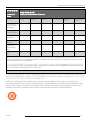
11.2.6 List of Video LUTs
You can modify or configure a new LUT to support the source video (from DVI-I IN port) if it is not automatically detected.
1. Check to see if the resolution of the local source video is listed in the encoder LUT library
2. If it is not, click "Add" to add a new entry
3. Configure or modify the following:
K5903085
46
Chapter 11: Video
Table 11-3: Default/Valid LUT Parameters
Field
Default
Name
"Default Entry" N/A
LUT ID.
N/A
1-169
Stereo?
No
Yes, No
Horiz. Resolution
1280
0-size of monitor (pixels)
Vert. Resolution
1024
0-size of monitor (pixels)
Refresh Rate
60.0
1-500 (Hz)
Pixel Clock Rate
100.0
20-330 (MHz)
Horiz. Front Porch
40
0-1000 (pixels)
Vert. Front Porch
40
0-1000 (lines)
Horiz. Back Porch
40
0-1000 (pixels)
Vert. Back Porch
40
0-1000 (lines)
Horiz. Sync
40
0-1000 (pixels)
Vert. Sync
40
0-1000 (lines)
Sampling Phase
0
-16-15
Vert. Margin
0
0-3
Horiz. Position
0
-135-375 (pixels)
Vert. Position
0
-25-50 (pixels)
Coarse Noise
10
1-256
Fine Noise
16
1-2048
Color Space
RGB
RGB, YPrPb
Charge Pump Curr
Auto
Auto, 50, 100, 150, 250, 350, 500, 750, 1500 (µA)
Red/Green/Blue Gain
128
0-255
Red/Green/Blue Offset 64
Valid Entries
0-127
l
Name: Name the LUT for future identification
l
LUT ID: Designates a unique ID number for the new LUT. The system will automatically suggest a unique number
for you
Stereo?: Enables stereo video for the LUT entry
Horiz. Resolution: Specify the horizontal resolution of the video (e.g. 1024)
Vert. Resolution: Specify the vertical resolution of the video (e.g. 768)
Refresh Rate: Specify the vertical refresh rate of the video
l
l
l
l
NOTE: See your video adaptor's documentation to obtain the proper horizontal and vertical timing
parameters.
l
47
Pixel Clock Rate: Enter the pixel clock of the video
NGS-D200 User Guide
Chapter 11: Video
l
l
l
l
l
l
l
l
Horiz. Front Porch: Specify the number of columns of horizontal front porch
Vert. Front Porch: Specify the number of lines of vertical front porch
Horiz. Back Porch: Specify the number of columns of horizontal back porch
Vert. Back Porch: Specify the number of lines of vertical back porch
Horiz. Sync: Specify the number of columns of horizontal synchronization
Vert. Sync: Specify the number of lines of vertical synchronization
Sampling Phase: The sampling phase is adjusted to minimize noise of the video source that is result of the
source's hardware (video card, cables, etc.) and video resolution. Ideally, this field should be set to a level that
minimizes bandwidth usage. You can check your bandwidth usage from the Display Connection Information page to
find a sampling phase that works best for your deployment.
Vert. Margin: Specify the margin for matching the detected vertical resolution of video input source with the vertical
resolution specified
NOTE: Typically for digital video, a Vert Margin of 0 (default) works well. For analog video, it is
recommended to use a Vert. Margin of 1 under normal circumstances. However, if the analog input signal is
not stable (e.g. the video travels through a very long cable), it is recommended to set a higher Vert Margin
(maximum of 3).
l
l
l
l
l
l
l
l
Horiz. Position: Specify the horizontal position of the source video. Only adjust this field if the video output is being
cut off on the left and right sides and adjusting the horizontal position of the monitor on the decoder side does not fix
the problem
Vert. Position: Specify the vertical position of the source video. Only adjust this field if the video output is being cut
off on the top and bottom and adjusting the vertical position of the monitor on the decoder side does not fix the
problem
Coarse Noise: Enter a lower order noise threshold below which two successive frames are considered identical. It
is not recommended to change this field
Fine Noise: Enter a higher order noise threshold below which two successive frames are considered identical. It is
not recommended to change this field
Color Space: Configure the input video for either RGB or YPrPb color models
Charge Pump Curr: This is current that drives the generation of the pixel clock internal to the encoder. When set to
"Auto," the system defaults to the optimal setting for the specific video input defined in the lookup table entry. It is
not recommended to change this setting
Red/Blue/Green Gain: Specify the range of red, blue, or green input signals. Setting higher values lowers the
contrast of images
Red/Blue/Green Offset: Specify the entire input range of color, changing the brightness of images
NOTE: When you have finished making changes, click "Apply" at the bottom of the page. Click "Save Settings" to
permanently save your changes to the device.
11.2.7 List of Preferred Timings in EDID to Source
If not using a custom resolution from the monitor, you may wish to force the device to use a specific LUT to process the
local input video.
NOTE: You will only expose this section of the page when the Use Preferred Video Timings from Monitor option is
disabled. For more information, see "Use Preferred Video Timings from Monitor" on page 43
Procedure:
1. Click "Add" to add a new EDID Descriptor
2. Select an LUT Id from the LUT library
K5903085
48
Chapter 11: Video
NOTE: If your required LUT is not in the available list, then you must configure one manually. For more
information, see "List of Video LUTs" on page 46
3. Select a descriptor number
NOTE: When you have finished making changes, click "Apply" at the bottom of the page. Click "Save
Settings" to permanently save your changes to the device.
49
NGS-D200 User Guide
Chapter 12: Audio
Chapter 12: Audio
The following topics are covered in this chapter:
51
12.1 Audio Mixer Configuration
12.1 Audio Mixer Configuration
The Audio Mixer allows you to adjust the volume of local audio or reverse audio coming from the decoder.
l
Local Audio: Enables you to change the volume of the local audio source (Line or Mic)
l
Remote Audio: Enables you to change the volume of the remote source
NOTE: When both fields are set to 100, each source will be equally mixed and at equal volume.
l
Audio Input: Specify if you wish to use the Line or Mic audio input
TIP: The Mic input (
)is located on the front of the unit and the Line input (
) is located on the rear.
NOTE: For encoders, Remote Audio changes the volume of reverse (bidirectional) audio coming from the
decoder.
51
NGS-D200 User Guide
Chapter 13: Keyboard/Mouse (KbM)
Chapter 13: Keyboard/Mouse (KbM)
The following topics are covered in this chapter:
13.1 How it Works
53
13.2 Overview of Keyboard/Mouse (KbM) Modes
53
13.3 Making Physical Connections
54
13.4 Making RFB Connections
55
13.5 KB/M Diagnostics
55
13.6 Keyboard Locale Settings
55
13.7 KB/M Settings
56
13.1 How it Works
The decoder is capable of controlling computers being encoded on the network. KbM bytes from the decoder can be
transmitted to the encoder (source) over the network. From the encoder, this KbM input data will be transmitted to the host
PC in one of twoways:
1. Through a hardwired USB output
2. Over RFB, where the host PC is running an instance of an RFB server and the encoder is configured as an
RFB client
13.2 Overview of Keyboard/Mouse (KbM) Modes
There are several different KbM modes that can be set for connected keyboard and mice.
13.2.1 Decoder
53
NGS-D200 User Guide
Chapter 13: Keyboard/Mouse (KbM)
Figure 13-1: Overview of Decoder KbM Modes
13.2.1.1 Local Mode
When set to “Local” Mode, the unit will only transmit KbM bytes through the HOST port (USB Type B) to the local PC. KbM
bytes will not be sent over the network.
13.2.1.2 Remote Mode
When set to “Remote” Mode, the decoder will transmit KbM bytes out over the IP network to any connected encoders
NOTE: For more information, see "Decoder Keyboard/Mouse Parameters" on page 56
13.3 Making Physical Connections
The connection instructions are the same for an encoder and a decoder.
13.3.1 USB Connection
Tools and equipment required
l
l
Type B- to-Type A USB patch cable
USB keyboard and/or USB mouse
Figure 13-2: Encoder connected to host PC (via USB connection) to allow KbM input to be transmitted
13.3.2 Procedure
1. Connect the Type B connector end of the USB patch cable into the HOST port on the back panel of the encoder
2. Connect the Type A end of the patch cable to a USB port on the host PC
3. Connect a USB keyboard and/or mouse to the USB port (Type A USB) on the unit
NOTE: Using a hardwired (physical) KbM connection provides absolute mouse control, but does not currently
support multi-head/multi-display sources in which the non primary screen is being encoded.
K5903085
54
Chapter 13: Keyboard/Mouse (KbM)
13.4 Making RFB Connections
The NGS-D200 encoder can run an instance of RFB client. This enables the system to be controlled by a source PC that is
running an instance of RFB server. When the encoder connects to a decoder, any keyboard/mouse data from the decoder
will be forwarded to the encoder (RFB client) which will in turn forward this to the source PC (RFB server).
You should use an RFB connection to:
l
l
support legacy V2D XP installations
support extended desktop use cases in which you need to encode and share the secondary (non-primary) screen
NOTE: When you connect the encoder as an RFB client to the host PC, all hardwired connections that were
transmitting KbM bytes to the host PC will be temporarily disabled. KbM data will only be forwarded logically from
the RFB client to the RFB server (host PC).
13.4.0.1 Tools and equipment required
l
l
Host PC running RFB server software
Encoder connected to host PC over the network
Figure 13-3: Encoder (RFB client) transmitting KbM bytes from the decoder to host PC (running RFB server software)
13.4.0.2 Procedure
l
Configure the encoder Keyboard/Mouse Server Parameters Menu. For more information, see "Encoder
Keyboard/Mouse Server Parameters" on page 38
13.5 KB/M Diagnostics
13.5.1 Encoder/Decoder KB/M Diagnostic Information
The KB/M Diagnostic Information section gives real-time information about keyboard/mouse configuration and traffic.
13.6 Keyboard Locale Settings
13.6.1 Encoder/Decoder Keyboard Layout
You can select the Keyboard Layout for the attached keyboard. This will ensure that key strokes are appropriately
exchanged between the collaborating source (encoder) and destination (decoder):
l
55
Keyboard Layout: Select the appropriate keyboard layout:US, German, French, Belgian French, Spanish, Dutch,
Italian, Portuguese, Russian, Chinese, English UK, Swiss French
NGS-D200 User Guide
Chapter 13: Keyboard/Mouse (KbM)
l
l
This setting must be configured on both the connected encoder and decoder
Only the same keyboard type can be used on both ends of the connection (e.g.if encoder is get to German and
decoder/software client should also be set to German)
NOTE: When you have finished making changes, click "Apply" at the bottom of the page. Click "Save Settings" to
permanently save your changes to the device.
13.7 KB/M Settings
13.7.1 Decoder Keyboard/Mouse Parameters
You can specify your keyboard and mouse type to ensure it is detected by the system as well as set the KbM Mode.
You can specify what KBM Mode you wish the decoder to operate in
l
KBM Mode: Configures the keyboard/mouse Mode:
o Local: The decoder will only transmit keyboard/mouse bytes out via the HOST port to control a local PC
o Remote: The decoder will transmit keyboard/mouse bytes out over the network to any connected encoders
K5903085
56
Chapter 14: Administration
Chapter 14: Administration
The following topics are covered in this chapter:
14.1 Administration
57
14.2 Management Settings
58
The Administration Menu allows you to configure the device to be used in either Managed or Standalone Mode
(connections with or without the use of a 4.x Management Server respectively), point the device to a Management Server
(when used in Managed Mode), and also change the default login credentials used to access the Web UI.
14.1 Administration
14.1.1 Management Status
NOTE: This menu is only applicable to users of the 4.x Collaboration Suite.
The Management Status section allows you to check to see if your device is logged in to the Management Server. This is
helpful if you are having trouble managing the system as part of a 4.x environment.
14.1.2 System Control
System control allows you reboot, shutdown, revert to defaults, and switch the gender of the NGS-D200.
l
l
l
l
Factory Reset: Resets the NGS-D200 to factory defaults
Reboot : Reboots the system
Shutdown : Initiates a system shutdown cycle
Encoder/Decoder: Switches the NGS-D200 from an encoder to decoder, or vice versa
NOTE: After changing the gender of the system, the system will reboot. After the system comes back online, make
sure to click "Save Settings" to ensure the device retains this selection.
14.1.3 Upgrade
You can upgrade the software/firmware version of the system.
NGS-D200 can be upgraded from
l
l
l
Web UI of the box,
BCS Management System (Refer to BCS Admin UI Guide)
TFN CMS system (Refer to TransForm N installation manual).
14.1.3.1 Procedure to upgrade via Web UI
Prerequisites - a webserver needs to be installed (if not already, a webserver like WampServer can be installed
http://www.wampserver.com/en/ )
1. Untar the NGS-D200 Firmware upgrade package into a directory. It will create a directory called IMAGES
2. Place the IMAGES folder in root folder of webserver (normally a directory on webserver like www)
57
NGS-D200 User Guide
Chapter 14: Administration
3. Log in to the WebUI of NGS-D200 that needs to be upgraded.
4. Go to Administration > Upgrade and configure the URL as follows and press "Upgrade" button. WEBSERVERIPADDRESS is the IP address of the webserver.
http://WEBSERVER-IPADDRESS/IMAGES
The box will reboot after upgrade goes through.
14.2 Management Settings
14.2.1 XMPP Agent
The XMPP Agent menu points the device to a Management Sever to be used in Managed Mode.
l
Configure the following:
o XMPP Enable: Enables the device to log on to the Management Server's XMPP server. Enable this if using
the device in Managed Mode
o
XMPP Sever IP/Name: Allows you to point the device to the IP address or host name of the Management
Server. Enter the IP address/host name of the Management Server
NOTE: If you are configuring this device as part of an environment that uses High Availability (HA),
then enter the primary Management Server virtual IP address or host/domain name after enabling
HA.
Device Name: Enter the "Device Name" that was entered into the Admin UI for the device
Password: Enter the "Device Password" that was entered in the Admin UI for the device
XMPP Server Port: Specifies the XMPP server port on the Management Server. This should be set to
"5222"
o XMPP Server Domain: Not currently in use
o
o
o
NOTE: When you have finished making changes, click "Apply" at the bottom of the page. Click "Save
Settings" to permanently save your changes to the device.
14.2.2 Admin Account
Admin Account allows you to configure the login password for accessing the device Web UI.
l
Admin Password: Enter a new password
NOTE: When you have finished making changes, click "Apply" at the bottom of the page. Click "Save Settings" to
permanently save your changes to the device.
NOTE: You will be automatically logged out of the Web UI. Enter your new password to continue.
14.2.3 Standalone Mode
This allows you to change the device from Managed to Standalone Modes. In Managed Mode, the device is used as part of
networked, centrally managed, collaboration solution under the control of the 4.x Barco Management Server. For more
K5903085
58
Chapter 14: Administration
information, see "Modes of Operation" on page 8
l
Standalone: Sets the device to be used in Standalone Mode
NOTE: When you have finished making changes, click "Apply" at the bottom of the page. Click "Save Settings" to
permanently save your changes to the device.
59
NGS-D200 User Guide
Appendix I: Supported Encoding/Decoding Resolutions
Appendix I: Supported Encoding/Decoding
Resolutions
The NGS-D200 Lite can support the following resolutions:
Format Resolution
Refresh
Rate (Hz)
Horiz
Front
Porch
Horiz
Sync
Horiz
Back
Porch
Vert Front Vert
Porch
Sync
Vert Back
Porch
Pixel Clock
(MHz)
ONYX2 1024x768
96.0
16
128
112
3
6
30
99.16
ONYX2 1280x1024
96.0
20
160
252
3
6
60
179.64
SUN
1280x1024
76.1
32
64
288
2
8
32
135.00
SUN
1280x1024
67.2
16
112
224
2
8
33
117.00
VESA
800x600
56.0
24
72
128
1
2
22
36.00
VESA
800x600
60.3
40
128
88
1
4
23
40.00
VESA
800x600
72.2
56
120
64
37
6
23
50.00
VESA
800x600
75.0
16
80
160
1
3
21
49.50
VESA
1024x768
60.0
24
136
160
3
6
29
65.00
VESA
1024x768
70.1
24
136
144
3
6
29
75.00
VESA
1024x768
75.0
16
96
176
1
3
28
78.75
VESA
1152x864
60.0
64
120
240
1
3
27
81.62
VESA
1280x720
73.0
72
136
208
1
3
27
92.98
VESA
1280x960
60.0
96
112
312
1
3
36
108.00
VESA
1280x1024
60.0
48
112
248
1
3
38
108.00
VESA
1280x1024
75.0
16
144
248
1
3
38
135.00
VESA
1440x900
60.0
80
152
232
1
3
28
106.50
VESA
1600x1200
60.0
64
192
304
1
3
46
162.00
VESA
1680x1050
60.0
104
176
280
3
6
30
146.3
CEA861
1920x1080p 60.0
88
48
144
4
5
36
148.5
CEA861
1280X720p
60.0
112
208
48
5
5
20
74.25
CVTRB
1280x800
59.9
48
32
80
3
6
14
71.00
CVTRB
1920x1080
59.9
48
32
80
3
5
23
138.50
61
NGS-D200 User Guide
Appendix I: Supported Encoding/Decoding Resolutions
Format Resolution
Refresh
Rate (Hz)
Horiz
Front
Porch
Horiz
Sync
Horiz
Back
Porch
Vert Front Vert
Porch
Sync
Vert Back
Porch
Pixel Clock
(MHz)
CVTRB
1920x1200
59.9
48
32
80
3
6
26
154.00
CVT
1152x900
59.9
64
120
184
3
10
21
85.00
CVT
1200x1600
59.9
88
128
216
3
10
45
162.25
CVT
1600x1200
75.0
120
168
288
3
4
48
204.75
CVT
1776x1056
59.9
112
184
296
3
10
27
155.00
The NGS-D200 Pro and NGS-D200 Pro 3D can support additional dual-link resolutions:
Refresh
Format Resolution
Rate (Hz)
Horiz
Front
Porch
Horiz
Sync
Horiz
Back
Porch
Vert Front Vert
Porch
Sync
Vert Back
Porch
Pixel Clock
(MHz)
CVTRB
2560x1600
59.9
48
32
80
3
6
37
268.50
IPV
2048x2048
59.97
48
32
80
3
10
46
279
IPV
3840x1080
59.9
64
64
192
3
9
19
277.00
IPV
3840x1200
59.9
64
64
192
3
10
22
308.00
NOTE: For questions about support for other resolutions not listed here, please contact Customer Support.
K5903085
62
Appendix II: Making a Simple Connection Between an NGS-D200 Encoder and Decoder
Appendix II: Making a Simple Connection
Between an NGS-D200 Encoder and Decoder
This section outlines how to directly connect Standalone NGS-D200 encoders to decoders.
II.1 Prerequisites
l
Both systems are operating in "Standalone" mode
II.2 Encoder Setup
1. Launch a web browser. In the address bar, enter the IP address/domain name of the NGS-D200 unit (e.g. 10.1.5.50)
2. Ensure the device is configured as an encoder and in "Standalone" mode. You will see this information on the top of
the Web UI.
l If the system is not, navigate to the Administration section of the page
o If not operating in Standalone Mode:
n Under the Standalone Mode section, check the box.
n At the bottom of the page, click "Apply"
n Click "Save Settings"
o If not an encoder:
n
Under the System Control section, click "Encoder/Decoder." The system will reboot and
come up as an encoder
NOTE: After the system boots and you log back in, make sure to click "Save Settings"
to ensure the device will continue to come up as an encoder after any subsequent
reboots.
TIP: You can configure the encoder streaming parameters by configuring the
Connection Profile section of the page. For more information, see "Connection Profile"
on page 28
II.3 Decoder (client) Setup
1. Launch a web browser. In the address bar, enter the IP address/domain name of the other NGS-D200 unit
2. Ensure the device is configured as a decoder and in "Standalone" mode. You will see this information on the top of
the Web UI
l If the system is not, navigate to the Administration section of the page:
o If not operating in Standalone Mode:
n Under the Standalone Mode section, check the box.
n At the bottom of the page, click "Apply"
n Click "Save Settings"
63
NGS-D200 User Guide
Appendix II: Making a Simple Connection Between an NGS-D200 Encoder and Decoder
o
If not a decoder:
n Under the System Control section, click "Encoder/Decoder." The system will reboot and come
up as a decoder.
NOTE: After the system boots and you log back in, make sure to click "Save Settings" to
ensure the device will continue to come up as an decoder after any subsequent reboots.
II.3.1 Create a list of Encoders to Connect to
You will need to create a list of encoders that the decoder can connect to.
1. On a standalone decoder, navigate to the Streaming section of the page
2. Under the Connection Manager section, click "Add"
3. Specify the encoder (server) you wish to connect to :
l Server: Enter the IP address or domain name of the encoder you will connect to
l
Port: Specify the server port to connect to
NOTE: The default server port is 6060.
Bandwidth: Specify the desired bandwidth for the connection (Mbps)
Multicast: Check the box to use a multicast connection
l Audio/Video: Select if the connect will support only video, only audio, or both
l Bidirectional: Check the box to enable bidirectional audio. The encoder side will be able to hear the
connected audio source
4. Click "Apply" at the bottom of the page, then click "Save Settings" to ensure the entry is permanently saved on the
decoder
l
l
II.3.2 Making a Connection
l
l
From the Connection Manager Table, click on the encoder that you wish to connect to. If you have the proper
authorization, you will connect to the encoder
If you wish to break an existing connection, click "Disconnect"
II.4 Get Information about the Connection
Navigate to the Connection Information section of the page. You will see real-time information about the connection:
network traffic, LUT used, connected server/client, etc.
K5903085
64
Appendix III: Stereo Emitter Cable Specifications
Appendix III: Stereo Emitter Cable
Specifications
NOTE: 3D/Stereoscopic video is only supported on the NGS-D200 Pro 3D. For information on upgrading to the Pro
3D, please contact Barco Sales.
NOTE: The 3D stereo kit (part number C9826147) is included with the NGS-D200 Pro 3D.
65
NGS-D200 User Guide
Appendix IV: Required Settings to Use KbM in 4.x Collaboration Suite
Appendix IV: Required Settings to Use KbM in
4.x Collaboration Suite
Using remote keyboard and mouse control in a managed 4.x environment requires several settings in the Admin UI
NOTE: All devices and users who wish to use remote desktop sharing must use a Route that applies a KbMenabled Profile. The default Route is not KbM-enabled.
l
Login to the Admin UI
Navigate to the "Profiles" tab
l
Ensure that selected Profile has the "Enabled Keyboard/Mouse" flag checked
l
Profiles Tab > Add Profile/Edit Profile > Config Tab > Keyboard Mouse Settings >
l
Enable Keyboard/Mouse
This Profile must be applied using the appropriately configured Route
ATTENTION: See the 4.x Admin UI Setup Guide for more on Policy Configuration.
67
NGS-D200 User Guide
Appendix V: Settings to Allow Remote Keyboard & Mouse (KbM) Control on Linux Systems
Appendix V: Settings to Allow Remote
Keyboard & Mouse (KbM) Control on Linux
Systems
In order to use Remote Keyboard & Mouse (KbM) Control on a Linux System, you will have to change several OS security
settings to authorize the encoder to communicate with the host PC.
V.1 Enabling KbM on a Fedora System
From the main Fedora desktop:
1.
2.
3.
4.
5.
Select Systems
Select Preferences
Select Internet and Network
Select Remote Desktop
Enable the following check boxes:
l "Allow other users to view your desktop"
l "Allow other users to control your desktop"
6. (Optional) Configure Security settings
Figure V-1: Remote Desktop Preferences
V.2 Enable KbM on a openSUSE System
From the main Suse Desktop:
69
NGS-D200 User Guide
Appendix V: Settings to Allow Remote Keyboard & Mouse (KbM) Control on Linux Systems
1.
2.
3.
4.
Click on Computer
Select Control Center
Select Remote Desktop
Enable the following check boxes:
l "Allow other users to view your desktop"
l "Allow other users to control your desktop"
5. (Optional) Configure Security settings
Figure V-2: Remote Desktop Preferences
K5903085
70
Appendix VI: RFB Keyboard ASCII Guide
Appendix VI: RFB Keyboard ASCII Guide
When using remote KbM on a decoder to control a source PC (that is connected to an encoder) keystrokes are processed
differently depending on the type of connection between the encoder and the source PC:
l
71
For hardwired USB connections between the encoder and host PC:
o All keystrokes are sent from the Rx in the same manner as a standard US 101 keyboard
o When the encoder is configured as an RFB client to the host PC (RFB server) certain keystrokes are sent as
follows:
n LGUI (L Windows key): 0x1f/0xffe7
n RGUI (R Windows key): 0x27/0xffe8
n Application: 0x2f/0xff20
n Print Screen/System Rq: 0xff15/0xff15
n Scroll Lock: 0xff13/0xff13
n Pause/Break: 0xff14/0xff14
NGS-D200 User Guide
Appendix VII: Safety and Compliance Statements
Appendix VII: Safety and Compliance
Statements
VII.1 Compliance Statements
Federal Communications Commission (FCC) Statement
This equipment has been tested and found to comply with the limits for a Class A digital device, pursuant to part 15 of the
FCC Rules. These limits are designed to provide reasonable protection against harmful interference when the equipment is
operated in a commercial environment. This equipment generates, uses, and can radiate radio frequency energy and, if not
installed and used in accordance with the instruction manual, may cause harmful interference to radio communications.
Operation of this equipment in a residential area is likely to cause harmful interference in which case the user will be
required to correct the interference at his own expense.
Barco is not responsible for any radio or television interference caused by unauthorized changes or modifications to this
equipment. Unauthorized changes or modifications could void the user’s authority to operate the equipment.
This device complies with Part 15 of the FCC Rules. Operation is subject to the following two conditions:
1. this device may not cause harmful interference, and
2. this device must accept any interference received, including interference that may cause undesired operation.
Industry Canada Class A Emission Compliance Statement
This Class A digital apparatus complies with Canadian ICES-003.
Avis de conformité à la réglementation d’Industrie Canada Cet appareil numérique de la classe A est conforme à la norme
NMB-003 du Canada.
Australia and New Zealand Class A Statement
Attention: This is a Class A product. In a domestic environment this product may cause radio interference in which case
the user may be required to take adequate measures.
European Union EMC Directive Conformance Statement
This product is in conformity with the protection requirements of EU Council Directive 2004/108/EC on the approximation
of the laws of the Member States relating to electromagnetic compatibility.
Barco cannot accept responsibility for any failure to satisfy the protection requirements resulting from a nonrecommended
modification of the product.
This product has been tested and found to comply with the limits for Class A Information Technology Equipment according
to CISPR 22/European Standard EN 55022. The limits for Class A equipment were derived for commercial and industrial
environments to provide reasonable protection against interference with licensed communication equipment.
Attention: This is a Class A product. In a domestic environment this product may cause radio interference in which case
the user may be required to take adequate measures
73
NGS-D200 User Guide
Appendix VII: Safety and Compliance Statements
VII.2 General Considerations
General safety instructions
l
l
l
l
l
Before operating this equipment please read this manual thoroughly and retain it for future reference
Installation and preliminary adjustments should be performed by qualified Barco personnel or by authorized Barco
service dealers
All warnings on the device and in the documentation manuals should be adhered to
All instructions for operating and use of this equipment must be followed precisely
All local installation codes should be adhered to
Notice on safety
This equipment is built in accordance with the requirements of the international safety standards IEC60950-1, EN60950-1,
UL60950-1 and CAN/CSA C22.2 No.60950-1, which are the safety standards of information technology equipment
including electrical business equipment. These safety standards impose important requirements on the use of safety
critical components, materials and insulation, in order to protect the user or operator against risk of electric shock and
energy hazard and having access to live parts. Safety standards also impose limits to the internal and external temperature
rises, radiation levels, mechanical stability and strength, enclosure construction and protection against the risk of fire.
Simulated single fault condition testing ensures the safety of the equipment to the user even when the equipment’s normal
operation fails.
VII.3 Important safety instructions
To prevent the risk of electrical shock
l
l
l
l
l
l
l
l
l
l
l
l
l
l
l
l
This product should be operated from a mono phase AC power source
This apparatus must be grounded (earthed) via the supplied 3 conductor AC power cable. If none of the supplied
power cables are the correct one, consult your dealer
If you are unable to insert the plug into the outlet, contact your electrician to replace your obsolete outlet. Do not
defeat the purpose of the grounding-type plug
Do not allow anything to rest on the power cord. Do not locate this product where persons will walk on the cord. To
disconnect the cord, pull it out by the plug. Never pull the cord itself
Use only the power cord supplied with your device. While appearing to be similar, other power cords have not been
safety tested at the factory and may not be used to power the device. For a replacement power cord, contact your
dealer.
Do not operate the device with a damaged cord. Replace the cord
Do not operate the device if the device has been dropped or damaged - until it has been examined and approved for
operation
by a qualified service technician.
Position the cord so that it will not be tripped over, pulled, or contact hot surfaces
If an extension cord is necessary, a cord with a current rating at least equal to that of the device should be used. A
cord rated for less amperage than the device may overheat
Never push objects of any kind into this product through cabinet slots as they may touch dangerous voltage points
or short out parts that could result in a risk of fire or electrical shock
Do not expose this device to rain or moisture
Do not immerse or expose this device in water or other liquids
Do not spill liquid of any kind on this device
Should any liquid or solid object fall into the cabinet, unplug the set and have it checked by qualified service
personnel before resuming operations
Do not disassemble this device, always take it to an authorized trained service person when service or repair work
is required
K5903085
74
Appendix VII: Safety and Compliance Statements
l
l
Do not use an accessory attachment which is not recommended by the manufacturer
Lightning - For added protection for this video product during a lightning storm, or when it is left unattended and
unused for long
To prevent personal injury
l
l
l
l
l
l
To prevent injury and physical damage, always read this manual and all labels on the system before connecting to
the wall outlet or adjusting the device
To prevent injury, ensure that all covers are correctly installed. See installation procedures
Before attempting to remove any of the device’s covers, you must turn off the device and disconnect from the wall
outlet
When required to switch off the device, to access parts inside, always disconnect the power cord from the power
net
The power input at the device side is considered as the disconnect device. When required to switch off the device,
to access parts inside, always disconnect the power cord at the device side. In case the power input at the device
side is not accessible, the socket outlet supplying the device shall be installed nearby the device and be easily
accessible, or a readily accessible general disconnect device shall be incorporated in the fixed wiring
Do not place this equipment on an unstable cart, stand, or table. The product may fall, causing serious damage to it
and possible injury to the user
To prevent fire hazard
l
l
l
l
l
Do not place flammable or combustible materials near the device!
Barco products are designed and manufactured to meet the most stringent safety regulations. This device radiates
heat on its external surfaces and from ventilation ducts during normal operation, which is both normal and safe.
Exposing flammable or combustible materials into close proximity of this device could result in the spontaneous
ignition of that material, resulting in a fire. For this reason, it is absolutely necessary to leave an “exclusion zone”
around all external surfaces of the device whereby no flammable or combustible materials are present. The
exclusion zone must be not less than 40 cm (16”). Do not cover the device with any material while the device is in
operation. Keep flammable and combustible materials away from the device at all times. Mount the device in a well
ventilated area away from sources of ignition and out of direct sun light. Never expose the device to rain or moisture.
In the event of fire, use sand, CO2 or dry powder fire extinguishers. Never use water on an electrical fire. Always
have service performed on this device by authorized Barco service personnel. Always insist on genuine Barco
replacement parts. Never use non-Barco replacement parts as they may degrade the safety of this device
Slots and openings in this equipment are provided for ventilation. To ensure reliable operation of the device and to
protect it from overheating, these openings must not be blocked or covered. The openings should never be blocked
by placing the device too close to walls, or other similar surface. This device should never be placed near or over a
radiator or heat register. This device should not be placed in a built-in installation or enclosure unless proper
ventilation is provided
Let the device cool down completely before storing. Remove cord from the device when storing
Heat sensitive materials should not be placed in the path of the exhausted air
To prevent device damage
l
l
l
75
The device must always be installed in a manner which ensures free flow of air into its air inlets and unimpeded
evacuation of the hot air from its cooling system
In order to ensure that correct airflow is maintained, and that the device complies with Electromagnetic
Compatibility (EMC) requirements, it should always be operated with all of it’s covers in place
Slots and openings in the cabinet are provided for ventilation. To ensure reliable operation of the product and to
protect it from overheating, these openings must not be blocked or covered. The openings should never be blocked
by placing the product on a bed, sofa, rug, or other similar surface. This product should never be placed near or over
a radiator or heat register. The device should not be placed in a built-in installation or enclosure unless proper
ventilation is provided
NGS-D200 User Guide
Appendix VII: Safety and Compliance Statements
l
l
l
l
l
Ensure that nothing can be spilled on, or dropped inside the device. If this does happen, switch off and unplug the
mains supply immediately. Do not operate the device again until it has been checked by qualified service personnel
Do not use this equipment near water
Save the original shipping carton and packing material. They will come in handy if you ever have to ship your
equipment. For maximum protection, repack your set as it was originally packed at the factory.
Unplug this product from the wall outlet before cleaning. Do not use liquid cleaners or aerosol cleaners. Use a damp
cloth for cleaning. Never use strong solvents, such as thinner or benzine, or abrasive cleaners, since these will
damage the cabinet. Stubborn stains may be removed with a cloth lightly dampened with mild detergent solution
Rated maximum ambient temperature, ta= 40 °C (104 °F)
On servicing
l
l
l
l
l
l
Do not attempt to service this product yourself, as opening or removing covers may expose you to dangerous
voltage potentials and risk of electric shock
Refer all servicing to qualified service personnel
Attempts to alter the factory-set internal controls or to change other control settings not specially discussed in this
manual can lead to permanent damage to the device and cancellation of the warranty
Unplug this product from the wall outlet and refer servicing to qualified service technicians under the following
conditions:
o When the power cord or plug is damaged or frayed
o If liquid has been spilled into the equipment
o If the product has been exposed to rain or water
o If the product does not operate normally when the operating instructions are followed. Adjust only those
controls that are covered by the operating instructions since improper adjustment of the other controls may
result in damage and will often require extensive work by a qualified technician to restore the product to
normal operation
o If the product has been dropped or the cabinet has been damaged
o If the product exhibits a distinct change in performance, indicating a need for service
Replacement parts: When replacement parts are required, be sure the service technician has used original Barco
replacement parts or authorized replacement parts which have the same characteristics as the Barco original part.
Unauthorized substitutions may result in degraded performance and reliability, fire, electric shock or other hazards.
Unauthorized substitutions may void warranty
Safety check: Upon completion of any service or repairs to this device, ask the service technician to perform safety
checks to determine that the product is in proper operating condition
K5903085
76
Appendix VIII: Environmental Statements
Appendix VIII: Environmental Statements
VIII.1 Disposal of the Product (Waste Electrical and Electronic
Equipment)
This symbol on the product indicates that, under the European Directive 2012/19/EU governing waste from
electrical and electronic equipment, this product must not be disposed of with other municipal waste. Please dispose of
your waste equipment by handing it over to a designated collection point for the recycling of waste electrical and electronic
equipment. To prevent possible harm to the environment or human health from uncontrolled waste disposal, please
separate these items from other types of waste and recycle them responsibly to promote the sustainable reuse of material
resources.
For more information about recycling of this product, please contact your local city office or your municipal waste disposal
service. For details, please visit the Barco website at: http://www.barco.com/en/AboutBarco/weee.
VIII.2 Turkey RoHS compliance
Türkiye Cumhuriyeti: AEEE Yönetmeliğine Uygundur
[Republic of Turkey: In conformity with the WEEE Regulation]
VIII.3 Chinese Mainland RoHS
中国大陆 RoHS
根 据 中 国 大 陆 《电 子 信 息 产 品 污 染 控 制 管 理 办 法 》( 也 称 为 中 国 大 陆 RoHS) ,以 下 部 分 列 出 了 Barco产 品 中 可 能
包 含 的 有 毒 和 /或 有 害 物 质 的 名 称 和 含 量 。中 国 大 陆 RoHS指 令 包 含 在 中 国 信 息 产 业 部 MCV标 准 :“电 子 信 息 产
品 中 有 毒 物 质 的 限 量 要 求 ”中 。
According to the “China Administration on Control of Pollution Caused by Electronic Information Products” (Also called
RoHS of Chinese Mainland), the table below lists the names and contents of toxic and/or hazardous substances that
Barco’s product may contain. The RoHS of Chinese Mainland is included in the MCV standard of the Ministry of
Information Industry of China, in the section “Limit Requirements of toxic substances in Electronic Information Products”.
77
NGS-D200 User Guide
Appendix VIII: Environmental Statements
零 件 项 目 (名 称 )
Component
Name
有毒有害物质或元素
Hazardous Substances or Elements
铅 (Pb)
汞 (Hg)
镉 (Cd)
六 价 铬 (Cr6+) 多 溴 联 苯
(PBB)
多溴二苯醚
(PBDE)
印制电路配件
Printed Circuit
Assemblies
X
O
O
O
O
O
外 接 电 (线 )缆
External Cables
X
O
O
O
O
O
散 热 片 (器 )
Heatsinks
O
O
O
O
O
O
底架
Chassis
O
O
O
O
O
O
电源供应器
Power Supply
Unit
X
O
O
O
O
O
风扇
Fan
O
O
O
O
O
O
O: 表 示 该 有 毒 有 害 物 质 在 该 部 件 所 有 均 质 材 料 中 的 含 量 均 在 SJ/T 11363-2006 标 准 规 定 的 限 量 要 求 以 下 .
O: Indicates that this toxic or hazardous substance contained in all of the homogeneous materials for this part is below
the limit requirement in SJ/T11363-2006.
X: 表 示 该 有 毒 有 害 物 质 至 少 在 该 部 件 的 某 一 均 质 材 料 中 的 含 量 超 出 SJ/T 11363-2006 标 准 规 定 的 限 量 要 求 .
X: Indicates that this toxic or hazardous substance contained in at least one of the homogeneous materials used for this
part is above the limit requirement in SJ/T11363 2006.
在 中 国 大 陆 销 售 的 相 应 电 子 信 息 产 品 ( EIP) 都 必 须 遵 照 中 国 大 陆 《电 子 信 息 产 品 污 染 控 制 标 识 要 求 》标 准 贴 上
环 保 使 用 期 限 ( EFUP) 标 签 。Barco产 品 所 采 用 的 EFUP标 签 ( 请 参 阅 实 例 ,徽 标 内 部 的 编 号 使 用 于 制 定 产 品 ) 基
于 中 国 大 陆 的 《电 子 信 息 产 品 环 保 使 用 期 限 通 则 》标 准 。
All Electronic Information Products (EIP) that are sold within Chinese Mainland must comply with the “Electronic
Information Products Pollution Control Labeling Standard” of Chinese Mainland, marked with the Environmental Friendly
Use Period (EFUP) logo. The number inside the EFUP logo that Barco uses (please refer to the photo) is based on the
“Standard of Electronic Information Products Environmental Friendly Use Period” of Chinese Mainland.
K5903085
78
Appendix IX: BARCO, INC. END USER LICENSE AGREEMENT
Appendix IX: BARCO, INC. END USER
LICENSE AGREEMENT
THIS LICENSE AGREEMENT IS THE LEGAL AGREEMENT ("AGREEMENT") BETWEEN YOU ("YOU") AND BARCO, INC. ("BARCO")
GOVERNING YOUR USE OF THE SOFTWARE THAT OPERATES WITH THIS BARCO PRODUCT ("SOFTWARE"). IF YOU DOWNLOAD AND
INSTALL THE SOFTWARE OR POWER UP OR OTHERWISE USE THE PRODUCT, YOU ARE INDICATING THAT YOU HAVE READ AND
UNDERSTOOD, AND AGREE TO BE BOUND BY, THE TERMS OF THIS AGREEMENT. IF YOU DO NOT AGREE TO THE TERMS AND
CONDITIONS OF THIS AGREEMENT, YOU SHOULD NOT DOWNLOAD OR INSTALL THE SOFTWARE, YOU ARE NOT GRANTED ANY RIGHTS
WHATSOEVER IN THE SOFTWARE AND YOU HAVE NO RIGHT TO USE THE PRODUCT.
LICENSES
Subject to the terms of this agreement, Barco grants you a nonexclusive, nontransferable license to run the SOFTWARE provided with the Product and
any updated versions downloaded by you only on and as incorporated in the Product. This is a license and not a sale. You shall not (i) copy or distribute,
sublicense, lease, rent or otherwise transfer the SOFTWARE to any third party except with and incorporated in the Product, and then not for value; (ii)
modify, adapt, alter, translate, or create derivative works of the SOFTWARE; (iii) decompile, disassemble, reverse engineer or otherwise derive source
code, or attempt to derive source code, from the SOFTWARE except to the extent Barco may, in certain jurisdictions, be required by law to permit
reverse engineering and provided that the provisions of such law may not be waived or conditioned on prior request for information regarding
interoperability; or (iv) have any of the foregoing done for you by a third party. The SOFTWARE and all intellectual property rights therein are the
exclusive property of Barco or its suppliers, except to the extent that the SOFTWARE contains Separately Licensed Code, as provided below. Barco
reserves the right to update the SOFTWARE from time to time in its sole discretion, including adding, changing or removing functionalities and features,
including but not limited to changing the user interface. All rights in and to the SOFTWARE not expressly granted to you in this Agreement are reserved
by Barco.
THRID PARTY NOTICES
You acknowledge and agree that at least some portions of the Licensed Materials may be based on industry recognized standards published by industry
recognized standards bodies and that certain third parties claim to own patents and copyrights that cover implementation of those standards. You
acknowledge and agree that this Agreement does not convey any license to any such third party patents, copyrights, and other intellectual property
rights and that You are solely responsible for any intellectual property infringement claims that relate to Your use of the Licensed Materials. Some of the
technology utilized in the Product is subject to third party licenses, which require that you be given this notice:
THIS PRODUCT IS LICENSED UNDER THE MPEG-4 VISUAL PATENT PORTFOLIO LICENSE FOR THE PERSONAL AND NON-COMMERCIAL
USE OF A CONSUMER FOR (i) ENCODING VIDEO IN COMPLIANCE WITH THE MPEG-4 VISUAL STANDARD (“MPEG-4 VIDEO”) AND/OR (ii)
DECODING MPEG-4 VIDEO THAT WAS ENCODED BY A CONSUMER ENGAGED IN A PERSONAL AND NON-COMMERCIAL ACTIVITY
AND/OR WAS OBTAINED FROM A VIDEO PROVIDER LICENSED BY MPEG LA TO PROVIDE MPEG-4 VIDEO. NO LICENSE IS GRANTED OR
SHALL BE IMPLIED FOR ANY OTHER USE. ADDITIONAL INFORMATION INCLUDING THAT RELATED TO ANY PROMOTIONAL, INTERNAL
AND COMMERCIAL USES AND LICENSING MAY BE OBTAINED FROM MPEG LA, LLC. SEE HTTP://WWW.MPLEGLA.COM.
THIS PRODUCT IS LICENSED UNDER THE AVC PATENT PORTFOLIO LICENSE FOR THE PERSONAL AND NON-COMMERCIAL USE OF A
CONSUMER TO (i) ENCODE VIDEO IN COMPLIANCE WITH THE AVC STANDARD (“AVC VIDEO”) AND/OR (ii) DECODE AVC VIDEO THAT WAS
ENCODED BY A CONSUMER ENGAGED IN A PERSONAL AND NON-COMMERCIAL ACTIVITY AND/OR WAS OBTAINED FROM A VIDEO
PROVIDER LICENSED BY MPEG LA TO PROVIDE AVC VIDEO. NO LICENSE IS GRANTED OR SHALL BE IMPLIED FOR ANY OTHER USE.
ADDITIONAL MAY BE OBTAINED FROM MPEG LA, LLC. SEE HTTP://WWW.MPLEGLA.COM.
WARRANTY DISCLAIMER
THE SOFTWARE IS PROVIDED "AS IS," WITHOUT ANY WARRANTY OF ANY KIND. BARCO DISCLAIMS ALL WARRANTIES, ORAL OR
WRITTEN, EXPRESS, IMPLIED, ARISING FROM COURSE OF DEALING OR USAGE OF TRADE, OR STATUTORY. ANY AND ALL OTHER
WARRANTIES, INCLUDING IMPLIED WARRANTIES OF MERCHANTABILITY, FITNESS FOR A PARTICULAR PURPOSE, TITLE,
NONINFRINGEMENT OF THIRD PARTY RIGHTS, QUIET ENJOYMENT AND ACCURACY ARE EXPRESSLY EXCLUDED. YOU SHALL NOT
HAVE THE RIGHT TO MAKE OR PASS ON, AND SHALL TAKE ALL MEASURES NECESSARY TO ENSURE THAT NEITHER YOU NOR ANY OF
YOUR DISTRIBUTORS, AGENTS, OR EMPLOYEES SHALL MAKE OR PASS ON ANY WARRANTY OR REPRESENTATION ON BEHALF OF
BARCO TO ANY THIRD PARTY.
LIMITATION OF LIABILITY
IN NO EVENT WILL BARCO OR ITS SUPPLIERS OR DISTRIBUTORS BE LIABLE FOR ANY CONSEQUENTIAL, SPECIAL, EXEMPLARY,
INCIDENTAL AND INDIRECT DAMAGES, OR FOR LOSS OF REVENUE OR PROFITS OR DATA OR USE OR FOR THE COST OF SUBSTITUTE
GOODS, WHETHER IN CONTRACT OR TORT (INCLUDING NEGLIGENCE), ARISING OUT OF, OR IN CONNECTION WITH THE SOFTWARE
OR YOUR USE THEREOF. IN NO EVENT WILL BARCO'S OR ITS SUPPLIERS' TOTAL CUMULATIVE LIABILITY RELATING TO THE SOFTWARE
EXCEED THE PURCHASE PRICE OF THE PRODUCT. SOME JURISDICTIONS DO NOT ALLOW THE EXCLUSION OF IMPLIED WARRANTIES
79
NGS-D200 User Guide
Appendix IX: BARCO, INC. END USER LICENSE AGREEMENT
OR LIMITATION OF LIABILITY FOR CERTAIN INCIDENTAL OR CONSEQUENTIAL DAMAGES, SO THE EXCLUSIONS SET FORTH ABOVE MAY
NOT APPLY TO YOU.
SUPPORT; EQUIPMENT
This Agreement does not entitle You to any support, upgrades, patches, enhancements, or fixes (collectively, "Support") for the Technology. Any such
Support for the Technology that may be made available by Barco, in its sole discretion, shall become part of the Technology and subject to this
Agreement. You shall be responsible for obtaining and maintaining any equipment or ancillary services needed to connect to, access, or otherwise use
the Technology, including, without limitation, modems, hardware, software, and long distance or local telephone service. You shall be responsible for
ensuring that such equipment or ancillary services are compatible with the Technology.
SOFTWARE UPGRADES, ETC.
If the Software enables You to receive Upgrades, You may elect at any time to receive these Upgrades either automatically or manually. If You elect to
receive Upgrades manually or You otherwise elect not to receive or be notified of any Upgrades, You may expose Your Barco Product and/or the
Software to serious security threats and/or some features within Your Barco Product and/or Software may become inaccessible. There may be
circumstances where we apply an Upgrade automatically in order to comply with changes in legislation, legal, security or regulatory requirements or as a
result of requirements to comply with the terms of any agreements Barco has with any third parties regarding Your Barco Product and/or the Software.
You will always be notified of any Upgrades being delivered to You. The terms of this license will apply to any such Upgrade unless the Upgrade in
question is accompanied by a separate license, in which event the terms of that license will apply.
TECHNICAL SUPPORT
This Agreement is neither a service nor a support contract. For information about Barco’s current technical support offerings and policies (including any
fees for support services), please contact us by mail at Barco Inc., 1287 Anvilwood Ave, Sunnyvale, CA 94089.
EXPORT
Software, including technical data, may be subject to U.S. export control laws and regulations and/or export or import regulations in other countries. You
agree to comply strictly with all such laws and regulations.
GOVERNMENT RIGHTS
The Software and Documentation qualify as "commercial items," as that term is defined at Federal Acquisition Regulation ("FAR") (48 C.F.R.) 2.101,
consisting of "commercial computer software" and "commercial computer software documentation" as such terms are used in FAR 12.212. Consistent
with FAR 12.212 and DoD FAR Supp. 227.7202-1 through 227.7202-4, and notwithstanding any other FAR or other contractual clause to the contrary
in any agreement into which this Agreement may be incorporated, Customer may provide to Government end user or, if this Agreement is direct,
Government end user will acquire, the Software and Documentation with only those rights set forth in this Agreement. Use of either the Software or
Documentation or both constitutes agreement by the Government that the Software and Documentation are "commercial computer software" and
"commercial computer software documentation," and constitutes acceptance of the rights and restrictions herein
GENERAL TERMS
If any portion of this Agreement is found to be void or unenforceable, the remaining provisions will remain in full force and effect. Each party recognizes
and agrees that the warranty disclaimers and liability and remedy limitations in this Agreement are material bargained for bases of this Agreement and
that they are reasonable and have been taken into account and reflected in determining the consideration to be given by each party under this
Agreement and in the decision by each party to enter into this Agreement. Barco’s distributors, contractors and agents are intended third party
beneficiaries under this Agreement. This Agreement constitutes the entire agreement between the parties with respect to the Software and supersedes
any conflicting or additional terms contained in any purchase order or elsewhere. Except as set forth in the above “License” Section or otherwise
expressly provided under this Agreement, no amendment to or modification of this Agreement will be binding unless in writing and signed by Barco and
You.
Barco and the Barco Logo and other trademarks contained in the Software and Documentation are trademarks or registered trademarks of Barco, its
licensors and third parties, as the case may be. You may not remove or alter any trademark, trade names, product names, logo, copyright or other
proprietary notices, legends, symbols or labels in the Software and Documentation. This Agreement does not authorize You to use Barco's or its
licensors' names or respective trademarks.
MISCELLANEOUS
This agreement is the final, complete and exclusive agreement between the parties relating to the SOFTWARE and supersedes all prior or
contemporaneous proposals, representations, understandings, or agreements relating thereto, whether oral or written. No waiver or modification of
this agreement will be valid unless signed by each party. Your right to use the SOFTWARE will immediately terminate upon any breach by you of this
agreement. The waiver of a breach of any term hereof will in no way be construed as a waiver of any other term or breach hereof. If any provision of this
agreement is held by a court of competent jurisdiction to be unenforceable, the remaining provisions of this agreement will remain in full force and effect.
This agreement shall be governed by the laws of the State of California without giving effect to any conflict of laws principles that may provide the
application of the law of another jurisdiction. Any action or proceeding arising from or relating to this agreement may be brought only in a federal court in
the Northern District of California or in state court in Santa Clara County, California, and each party irrevocably submits to the jurisdiction and venue of
any such court in any such action or proceeding. The United Nations Convention on Contracts for the International Sale of Goods shall not apply to this
agreement. Should you have any question about this agreement, or if you desire to contact Barco, please contact us by mail at Barco Inc., 1287
Anvilwood Ave, Sunnyvale, CA 94089.
K5903085
80
Appendix IX: BARCO, INC. END USER LICENSE AGREEMENT
SOFTWARE LICENSING PROVISIONS:
EACH SEPARATE OPEN SOURCE SOFTWARE COMPONENT AND ANY RELATED DOCUMENTATION ARE PROVIDED "AS IS" WITHOUT
EXPRESS OR IMPLIED WARRANTY INCLUDING, BUT NOT LIMITED TO, THE IMPLIED WARRANTIES OF MERCHANTABILITY AND FITNESS
FOR A PARTICULAR PURPOSE. IN NO EVENT SHALL THE COPYRIGHTHOLDER OR ANY OTHER CONTRIBUTOR BE LIABLE FOR DIRECT,
INCIDENTAL OR CONSEQUENTIAL DAMAGES, EVEN IF ADVISED OF THE POSSIBILITY OF SUCH DAMAGES. MORE INFORMATION
/DETAILS IS TO BE FOUND IN EACH SPECIFIC OPEN SOURCE LICENSE.
Copyright on each Open Source Software component belongs to the respective initial copyright holder, each additional contributor and/or their
respective assignee(s), as may be identified in the respective documentation, source code, README file, or otherwise. You shall not remove or obscure
or otherwise alter the respective copyrights.
You acknowledge living up to the conditions of each separate Open Source Software license.
For the complete list of open source software and private licenses used in the system, please contact Barco.
TRADEMARK
Brand and product names mentioned in this manual may be trademarks, registered trademarks or copyrights of their respective holders. All brand and
product names mentioned in this manual serve as comments or examples and are not to be understood as advertising for the products or their
manufacturers.
81
NGS-D200 User Guide