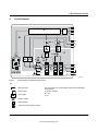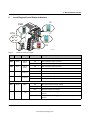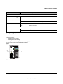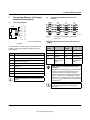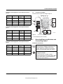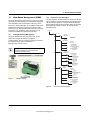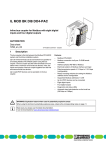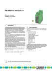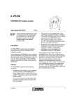
1
IL EIP BK DI8 DO4 2TX-PAC
I2
Inline Bus Coupler for Ethernet/IP With Eight Digital
Inputs and Four Digital Outputs
4 2T
DO
DI8 758
P BK 97
IL EI -No.: 28xx .xx
er /x xx
Ord W: xx xx.xx.
/F
HW Addr.: IP
et
MAC
X-PA
rN
e
Eth
RE
SE
AC
AUTOMATION
I1
O1
D
PWR
BO
ance
rm
confo
LN
C
d
teste
RY
MS
UL
NS
US
S1
UM
E
2
1
4
3
2
1
4
3
7
5
8
6
T
T1
K1
X1
AC
LN
T2
K2
X2
Data Sheet
7537_en_00
1
© PHOENIX CONTACT - 01/2008
Description
1.1
The bus coupler is the interface between the Ethernet/IP
network and the Inline installation system.
With the help of a bus coupler, 61 Inline terminals can be
connected at any position within an existing Ethernet/IP
system. The bus coupler and the Inline terminals form a
station with 63 local bus devices. Here, the inputs and
outputs of the bus coupler form the first and second local bus
devices.
Up to eight PCP devices can be operated on the bus
coupler.
–
–
–
–
–
–
–
–
–
–
–
Module Features
2 x Ethernet twisted pair according to 802.3 with auto
negotiation and auto crossover connected via an
integrated 3-port switch (2 external ports, 1 internal port)
Ethernet connection via 8-pos. RJ45 female connector
Ethernet TCP/IP, with 10/100 Base-T (X)
Industrial Ethernet/IP, Version 1.2
Process data access via XML
Web-based management (WBM)
IP parameter configuration:
BootP, DHCP, WBM, Static IP
Integrated web server
Eight digital inputs
Four digital outputs
Diagnostic and status indicators
For additional information, please refer to the UM EN IL EIP BK DI8 DO4 2TX-PAC user manual (see
"Documentation" on page 4).
This data sheet is only valid in association with the IL SYS INST UM E user manual (see "Documentation" on
page 4).
Make sure you always use the latest documentation.
It can be downloaded at www.download.phoenixcontact.com.
A conversion table is available on the Internet at
www.download.phoenixcontact.com/general/7000_en_00.pdf.
www.phoenixpowersupply.co.uk
IL EIP BK DI8 DO4 2TX-PAC
1.2
–
–
–
–
1.3
–
–
–
–
–
–
–
Inline Features
Up to 61 other Inline modules can be connected
(process data channel)
Up to eight other PCP modules can be connected
Can be installed in the field, software for automatic
configuration of the station is not required
Automatic baud rate detection on the local bus
(500 kbaud or 2 Mbaud)
Ethernet and CIP Features
Electrical isolation of Ethernet interface and logic
Type of device profile: 0Chex communication adapter
Supported CIP connections in total:
128 (eight, typical)
Explicit signaling:
Max. number of connections 128 (eight, typical)
I/O signaling:
Max. number of connections 128 (eight, typical)
Device configuration possibilities:
EDS, individual software
MAC parameter configuration:
rate: 10 Mbps, 100 Mbps, automatic
duplex: half, full, automatic
7537_en_00
PHOENIX CONTACT
www.phoenixpowersupply.co.uk
2
IL EIP BK DI8 DO4 2TX-PAC
Table of Contents
1
Description.................................................................................................................................. 1
1.1
1.2
1.3
Module Features ............................................................................................................................................ 1
Inline Features ............................................................................................................................................... 2
Ethernet and CIP Features ............................................................................................................................ 2
2
Ordering Data ............................................................................................................................. 4
3
Technical Data............................................................................................................................ 5
4
Circuit Diagram........................................................................................................................... 9
5
Local Diagnostic and Status Indicators .....................................................................................10
6
Reset Button..............................................................................................................................12
7
Connecting Ethernet, the Supply, Actuators, and Sensors .......................................................13
7.1
7.2
7.3
Connecting Ethernet .................................................................................................................................... 13
Connecting the Supply, Actuators, and Sensors.......................................................................................... 13
Connection Example .................................................................................................................................... 14
8
Mounting/Removing Modules and Connecting Cables..............................................................14
9
Startup..................................................................................................................................................................... 15
9.1
9.2
9.3
Default Upon Delivery/Default Settings........................................................................................................ 15
Starting the Firmware................................................................................................................................... 15
Sending BootP Requests ............................................................................................................................. 15
10 Ethernet/IP Object Classes .......................................................................................................15
11 Operating Directives for the System..........................................................................................16
11.1
11.2
Repeat Packet Interval (RPI) Settings ......................................................................................................... 16
Maximum Connection .................................................................................................................................. 16
12 CIP Object Classes ............................................................................................................................................. 16
13 Web-Based Management (WBM)..............................................................................................17
13.1
13.2
13.3
13.4
13.5
13.6
13.7
Calling Web-Based Management ................................................................................................................ 17
Structure of the Web Pages ......................................................................................................................... 17
"IP Configuration" Menu............................................................................................................................... 18
Password Protection .................................................................................................................................... 18
Firmware Update via WBM and TFTP ......................................................................................................... 18
Process Data Access via XML ..................................................................................................................... 19
XML File Structure ....................................................................................................................................... 19
14 Startup Behavior of the Bus Coupler .........................................................................................22
15 Configuration of the PCP PDU Size ..........................................................................................24
7537_en_00
PHOENIX CONTACT
www.phoenixpowersupply.co.uk
3
IL EIP BK DI8 DO4 2TX-PAC
2
Ordering Data
Bus Coupler
Description
Type
Inline bus coupler for Ethernet/IP with eight digital inputs and four digital
IL EIP BK DI8 DO4 2TX-PAC
outputs; including accessories (end plate, Inline connector and labeling fields)
Order No.
Pcs./Pkt.
2897758
1
Pcs./Pkt.
Accessories
Description
Type
Order No.
Connector set for Inline bus coupler with connected I/Os
IL BKDIO-PLSET
2878599
1
Gray RJ45 connector set for linear cable
FL PLUG RJ45 GR/2
2744856
2
Green RJ45 connector set for crossed cable
FL PLUG RJ45 GN/2
2744571
2
Keying profile
CP-MSTB
1734634
100
Zack marker strip to label the terminals
ZB 6 ... see CLIPLINE catalog
1051003
10
Zack marker strip to label the terminals
ZB 12 ... see CLIPLINE catalog
0812120
10
Labeling field covering one connector
IB IL FIELD 2
2727501
10
Labeling field covering four connectors
IB IL FIELD 8
2727515
10
Insert strips for IB IL FIELD 2, perforated, can be labeled using a laser printer,
marker pen or CMS system (72 sheets)
ESL 62X10
0809492
1
Insert strips for IB IL FIELD 8, perforated, can be labeled using a laser printer,
marker pen or CMS system (15 sheets)
ESL 62X46
0809502
5
DIN EN 50022 DIN rail, 2 meters
NS 35/7,5 PERFORATED
NS 35/7,5 UNPERFORATED
0801733
0801681
1
1
End clamp can be snapped on without tools
CLIPFIX 35-5
3022276
50
End clamp can be fixed using screws
E/UK
1201442
50
Additional System Components
Description
Type
Order No.
Pcs./Pkt.
Double sheathed Ethernet cable
FL CAT5 HEAVY
2744814
1 meter
Flexible Ethernet cable
FL CAT5 FLEX
2744830
1 meter
Media converter 660 nm
FL MC 10BASE-T/FO POF
2744513
1
Voltage supplies
QUINT-PS ... see INTERFACE catalog
Tools
Description
Type
Order No.
Pcs./Pkt.
Assembly tool for RJ45 connector
FL CRIMPTOOL
2744869
1
Screwdriver according to DIN 5264, blade width 3.5 mm
SZF 1-0,6X3,5
1204517
10
Pcs./Pkt.
Software
Description
Type
Order No.
BootP IP Addressing Tool
IPAssign.exe
This software can be downloaded at
www.download.phoenixcontact.com.
Documentation
Description
Type
Order No.
"Inline Bus Coupler for Ethernet/IP With Eight Digital Inputs and Four Digital
Outputs" user manual
UM EN IL EIP BK DI8 DO4 2TX-PAC
–
"I/O Modules at Bus Couplers" application note
AH IL BK IO LIST
9015358
1
"Automation Terminals of the Inline Product Range" user manual
IL SYS INST UM E
2698737
1
7537_en_00
Pcs./Pkt.
PHOENIX CONTACT
www.phoenixpowersupply.co.uk
4
IL EIP BK DI8 DO4 2TX-PAC
3
Technical Data
General Data
Housing dimensions (width x height x depth)
80 mm x 121 mm x 70 mm
Weight
270 g with connectors
Ambient temperature (operation)
-25°C to +60°C
Ambient temperature (storage/transport)
-25°C to +85°C
Permissible humidity (storage/transport)
10% to 95%, according to EN 61131-2
Permissible air pressure (operation/storage/transport)
70 kPa to 106 kPa (up to 3000 m above sea level)
Degree of protection
IP20 according to IEC 60529
Class of protection
Class 3, according to EN 61131-2, IEC 61131-2
Preferred mounting position
Perpendicular to a standard DIN rail
Connection to functional earth ground
The functional earth ground must be connected to the 24 V DC supply/
functional earth ground connection. The contacts are directly connected to the
potential jumper and FE springs on the bottom of the housing. The terminal is
grounded when it is snapped onto a grounded DIN rail. Functional earth
ground is only used to discharge interference.
Ambient compatibility
Free of substances which would hinder coating with paint or varnish
Resistance to solvents
Resistant to standard solvents
Connection data for Inline connectors
Connection type
Spring-cage terminals
Conductor cross-section
0.2 mm2 to 1.5 mm2 (solid or stranded), 24 -16 AWG
System Limits of the Bus Coupler
Number of devices per station
63, maximum (including two devices on the bus coupler)
Number of I/O data
512 bytes, maximum
Transmission rate on the local bus
500 kbps or 2 Mbps (automatic detection)
Power supply at UL (7.5 V)
0.8 A, maximum
Power supply at UANA
0.5 A, maximum
Power supply at US
8 A, maximum
Power supply at UM
8 A, maximum
Interfaces
Ethernet
Type
Ethernet
10Base-T and 100Base-TX with auto negotiation and auto crossover
Number
Two
Connection format
8-pos. RJ45 female connector
Connection medium
CAT 5 twisted pair cable
with a conductor cross section of 0.14 mm2 to 0.22 mm2
Cable impedance
100 :
Transmission speed
10 Mbps (10Base-T), 100 Mbps (100Base-TX)
half duplex, full duplex (auto detection)
Maximum network segment extension
Local bus
100 m
Through data routing
Supply Voltage for UL, US, UM
Recommended cable lengths
30 m, maximum; routing cables through outdoor areas is not admissible
Continuation
Through potential routing
Special demands on the voltage supply
The supplies UM/US and the bus coupler supply UBK do not have the same
ground potential because they are supplied by two separate power supply
units.
Behavior in the event of voltage fluctuations
Voltages (main and segment supply) that are transferred from the bus coupler
to the potential jumpers follow the supply voltages without delay.
Nominal value
24 V DC
7537_en_00
PHOENIX CONTACT
www.phoenixpowersupply.co.uk
5
IL EIP BK DI8 DO4 2TX-PAC
Supply Voltage for UL, US, UM (Continued)
Permissible range (according to EN 61131-2)
19.2 V to 30 V (ripple included)
NOTE: Module is damaged in the event of overload
This 24 V area must be externally protected. The power supply unit must be able to supply 4 times the nominal current of the external fuse,
to ensure that it trips in the event of an error.
Observe the logic current consumption of each device when configuring an Inline station. This information is given in every module-specific
data sheet. The current consumption can differ depending on the individual module. The permissible number of devices that can be
connected therefore depends on the specific station structure.
Communications Power UL (7.5 V) and Analog Supply UANA
The bus coupler supply UL (24 V) generates the communications power UL (7.5 V) and the analog supply UANA (24 V) for the Inline station.
- Communications Power (Potential Jumper)
Nominal value
7.5 V DC
Maximum output current
2 A DC (observe derating)
Safety equipment
Electronic short-circuit protection
- Analog Supply (Potential Jumper)
Nominal value
24 V DC
Maximum output current
0.5 A DC (observe derating)
Safety equipment
Electronic short-circuit protection
Current Consumption/Power Consumption
Current consumption from UL (24 V)
Current consumption of module electronics
0.08 A, maximum
Current consumption of local bus (800 mA load at 7.5 V)
0.4 A, maximum
Current consumption from UANA (24 V)
0.5 A, maximum
Total current consumption from UL
0.98 A, maximum
Current consumption from US (24 V)
3 mA +4 mA for each output set + load, typical; 8 A, maximum
Current consumption from UM (24 V)
3 mA +3 mA for each output set + load, typical; 8 A, maximum
Power dissipation of entire device
3 W, typical
Bus Interface of the Lower-Level System Bus
Interface
Inline local bus
Electrical isolation
No
Number of Inline terminals that can be connected
Limitation by software
Limitation by power supply unit
63, maximum
Maximum logic current consumption of the connected local bus modules:
Imax d 2 A DC
Observe the logic current consumption of each device when configuring an Inline station. This information is given in every module-specific
data sheet. The current consumption can differ depending on the individual module. The permissible number of devices that can be
connected therefore depends on the specific station structure.
Digital Outputs
Number
4
Connection method for actuators
2 and 3-wire technology
Nominal output voltage UOUT
24 V DC
Differential voltage at Inom
1 V
Nominal current Inom per channel
0.5 A
Total current
2A
7537_en_00
PHOENIX CONTACT
www.phoenixpowersupply.co.uk
6
IL EIP BK DI8 DO4 2TX-PAC
Digital Outputs (Continued)
Protection
Short circuit; overload
Nominal load
Ohmic
12 W
Lamp
12 W
Inductive
12 VA (1.2 H)
Switching frequency with nominal inductive load
0.5 Hz (1.2 H), maximum
Overload response
Auto restart
Response with inductive overload
Output may be damaged
Reverse voltage protection against short pulses
Protected against reverse voltages
Resistance to permanently applied reverse voltages
Protected against reverse voltages, permissible current 2 A, maximum
Response upon power down
The output follows the supply voltage without delay.
Limitation of the voltage induced on circuit interruption
-30.0 V, approximately
Safety equipment
Integrated free running circuit in the output chip
Overcurrent shutdown
0.7 A, minimum
Maximum output current when switched off
10 μA
When not loaded, a voltage can be measured even at an output that is not set.
Digital Inputs
Number
8
Connection method for sensors
2 and 3-wire technology
Input design
According to EN 61131-2 Type 1
Definition of switching thresholds
Maximum low-level voltage
ULmax < 5 V
Minimum high-level voltage
UHmin > 15 V
Common potentials
Sensor supply UM, ground
Nominal input voltage UIN
24 V DC
Permissible range
-30 V < UIN < +30 V DC
Nominal input current for UIN
3 mA, typical
Current flow
Limited to a 3 mA, maximum
Delay time
500 ms
Permissible cable length to the sensor
100 m
Use of AC sensors
AC sensors in the voltage range < UIN are limited in application
Safety equipment
Surge voltage, polarity reversal
Error message to the higher-level control system
Sensor supply not present
Mechanical Requirements
Vibration test sinusoidal vibrations according to IEC 60068-2-6;
EN 60068-2-6
5g load, 2 hours in each space direction
Shock test according to IEC 60068-2-27; EN 60068-2-27
25g load for 11 ms, half sinusoidal wave,
three shocks in each space direction and orientation
Mechanical Tests
Shock test according to EN 60068-2-27
Operation: 25g, 11 ms period, half-sine shock pulse
Storage/transport: 50g, 11 ms period, half-sine shock pulse
Vibration resistance according to IEC 60068-2-6
Operation/storage/transport: 5g, 150 Hz, Criterion A
Free fall according to IEC 60068-2-32
1m
7537_en_00
PHOENIX CONTACT
www.phoenixpowersupply.co.uk
7
IL EIP BK DI8 DO4 2TX-PAC
Conformance With EMC Directives
Developed according to IEC 61000-6.2
IEC 61000-4-2 (ESD)
Criterion B
6 kV contact discharge
6 kV air discharge (without labeling field)
8 kV air discharge (with labeling field)
IEC 61000-4-3 (radiated noise immunity)
Criterion A
IEC 61000-4-4 (burst)
Criterion B
IEC 61000-4-5 (surge)
Criterion B
IEC 61000-4-6 (conducted noise immunity)
Criterion A
IEC 61000-4-8 (noise immunity against magnetic fields)
Criterion A
EN 55011 (noise emission)
Class A
Approvals
Information on current approvals can be found on the Internet at www.download.phoenixcontact.com or www.eshop.phoenixcontact.com.
7537_en_00
PHOENIX CONTACT
www.phoenixpowersupply.co.uk
8
IL EIP BK DI8 DO4 2TX-PAC
4
Circuit Diagram
IB
μP
B
DO1...4
DI1...8
U L+
UANA
UL
8 x DI
7,5V
C
24V
24V
24V
4x
DO
US
UM
A
US
UL
UM
2 TX ETH
PWR
7275A005
Figure 1
Circuit diagram of the Ethernet Bus Coupler
Key:
µ P
IB
Microprocessor
The gray areas in the circuit diagram represent the electrically
isolated areas.
Protocol chip
A: Ethernet interface
B: Logic
C: I/O
Optocoupler
Ethernet switch
PNP transistor
Transmitter with electrical isolation
7537_en_00
PHOENIX CONTACT
www.phoenixpowersupply.co.uk
9
IL EIP BK DI8 DO4 2TX-PAC
5
Local Diagnostic and Status Indicators
I2
PWR
I2
PWR
BF BO
DIA UL
US
UM
X
4 2T
DO
DI8
BK 97758
TH
IL E -No.: 28xx .xx
er /x xx
Ord W: xx xx.xx.
/F
HW Addr.: IP
C
et
MA
ETH
E
LNK1
BF
RY
MS
NS
S1 -PAC
rN
the
ACT1
ance
rm
confo
d
teste
5 6
7 8
I2
I1
O1
D
PWR
BO
UL
US
UM
RY
MS
NS
S1
E
2
1
4
3
2
1
4
3
7
5
8
6
I1
I1
DIA
LNK2
ACT2
1 2
3 4
T
SE
RE
T1
AC
LN
O1
D E
K1
X1
T2
AC
LN
K2
1 2
3 4
X2
O1
6
75370002
Figure 2
LED
Indicators on the bus coupler
Color
Meaning
State
Description of the LED States
Green
Link at
port 1
ON
Link connection at port 1 present
OFF
Link connection at port 1 not present
ON
Link connection at port 2 present
OFF
Link connection at port 2 not present
ON
Data transmission on port 1 active
OFF
Data transmission on port 1 not active
ON
Data transmission on port 2 active
OFF
Data transmission on port 2 not active
ON
Boot loader active, firmware started
ETH
LNK1
LNK2
ACT1
ACT2
Green
Yellow
Yellow
Link at
port 2
Activity
on port 1
Activity
on port 2
PWR
BO
UL
Green
Green
Boot
ULogic
Flashing
Waiting for BootP/DHCP reply
OFF
Firmware started successfully
ON
24 V communications supply / 7.5 communications power
present
OFF
24 V communications supply / 7.5 communications power not
present
7537_en_00
PHOENIX CONTACT
www.phoenixpowersupply.co.uk
10
IL EIP BK DI8 DO4 2TX-PAC
LED
Color
Meaning
State
US
Green
USegment
ON
24 V segment circuit supply present
OFF
24 V segment circuit supply not present
UM
RY
MS
Green
Green
Red/
green
UMain
ON
24 V I/O supply present
OFF
24 V I/O supply not present
Ready
Module
status
Description of the LED States
Ready
ON
Connection to a process data client established
Flashing
Firmware ready to operate
OFF
Firmware not active
Device status
Green ON
Normal operation
Red ON
Unrecoverable error
Flashing green
–
–
NS
Green/
red
Network
status
Device not configured, or device configuration not complete
or faulty
Device in standby mode
Flashing red
Recoverable error
Flashing redgreen
Selftest
OFF
No supply voltage
Network status
Green ON
Module is online and has established a connection
Red ON
Error preventing communication with the network
(e.g., bus offline or double MAC ID).
Flashing green
Device online, connections not established
Device has finished the "double MAC ID" test but has not
established connections to other nodes.
Flashing red
One or more connections in timeout state
Flashing redgreen
Selftest
OFF
Device not online
Device has not yet finished the "double MAC ID" test.
Device has no IP address or is not supplied with voltage.
S1
Green
Boot
source
status
ON
IP parameters received from BootP/DHCP server
Flashing
BootP request/responses in process
OFF
Stored IP parameters are used
7537_en_00
PHOENIX CONTACT
www.phoenixpowersupply.co.uk
11
IL EIP BK DI8 DO4 2TX-PAC
LED
Color
Meaning
State
Description of the LED States
Green
Diagnostics
ON
Data transmission within the station active
Flashing
Data transmission within the station not active
Error
ON
Short circuit/overload of outputs
OFF
No short circuit/overload of outputs
ON
Outputs active
OFF
Outputs not active
ON
Inputs active
OFF
Inputs not active
O1
D
E
Red
1-4
Yellow
O1...O4
I1, I2
1-8
6
Yellow
I1...I8
Reset Button
The reset button is on the front side of the bus coupler.
It has two functions:
– Restarting the bus coupler
– Restoring the default settings
For restoring the default settings (see "Startup" on page 15)
the reset button must be pressed when the voltage is
applied.
IL EIP BK DI8 DO4 2TX-PAC
Order-No.: 2897758
HW/FW: xx/xxx
MAC Addr.: xx.xx.xx.xx
Ethernet IP
PWR
O1
I1
BO RY
D E
UL MS
US NS
UM S1
1
3
2
4
I2
1
3
2
4
5 7
6 8
conformance tested
RESET
RESET
LNK1
ACT1
LNK2
ACT2
X1
X2
75370003
Figure 3
Reset button
7537_en_00
PHOENIX CONTACT
www.phoenixpowersupply.co.uk
12
IL EIP BK DI8 DO4 2TX-PAC
7
Connecting Ethernet, the Supply,
Actuators, and Sensors
7.1
Connecting Ethernet
7.2
1.1
RJ45
Figure 4
Pin 1
TD+
Pin 2
TD-
Pin 3
RD+
Pin 4
res.
Pin 5
res.
Pin 6
RD-
Pin 7
res.
Pin 8
res.
1.2
1.3
1.4
Connecting the Supply, Actuators, and
Sensors
PWR
O1
I1
I2
1.1 2.1
1.1 2.1
1.1 2.1
3.1 4.1
1
1
1.2 2.2
2
2
1.3 2.3
3
3
1.4 2.4
4
4
2.1 1.1
2.2 1.2
2.3 1.3
2.4 1.4
1
Connect Ethernet to the bus coupler via an 8-pos. RJ45
connector. For the pin assignment, please refer to the
following table:
1.2 2.2
2
2
1.3 2.3
3
3
1.4 2.4
4
4
2.1 1.1
2.2 1.2
2.3 1.3
2.4 1.4
2
Figure 5
Pin assignment of the 8-pos. RJ45 female
connector
1
1
1
1
1.2 2.2
2
2
1.3 2.3
3
3
1.4 2.4
4
4
2.1 3.1
2.2 3.2
2.3 3.3
2.4 3.4
3
1
1
4.1
2
4.2
3.2 4.2
2
3.3 4.3
3
3
3.4 4.4
4
4
4.3
4.4
4
75370008
Terminal point assignment of the Inline
connectors
Terminal Point Assignment of the Power Connector
(1, PWR)
Terminal
Points
Assignment
Terminal
Points
Assignment
1.1
US
2.1
UM
Pin
Assignment
1.2
UL
2.2
UM
1
TxD + (transmit data +)
1.3
GND UL
2.3
GND UM, US
2
TxD - (transmit data -)
1.4
2.4
3
RxD + (receive data +)
Functional
earth ground
(FE)
Functional
earth ground
(FE)
4
Reserved
5
Reserved
6
RxD - (receive data -)
7
Reserved
8
Reserved
NOTE: Module is damaged in the event of
overload
Both Ethernet interfaces have an auto crossover
function.
The GND UM, US potential jumper carries the total
current of the main and segment circuits. The
total current must not exceed the maximum
current carrying capacity of the potential jumpers
(8 A). If, in the course of configuring, it is found
that the 8 A limit is reached at one of the potential
jumpers US, UM and GND, a new power terminal
must be used.
The functional earth ground must be connected to
the 24 V DC supply/functional earth ground
connection.
7537_en_00
PHOENIX CONTACT
www.phoenixpowersupply.co.uk
13
IL EIP BK DI8 DO4 2TX-PAC
Terminal Point Assignment of the Output Connector
(2, O1)
Terminal
Points
Assignment
Terminal
Points
Assignment
1.1
OUT1
2.1
OUT2
1.2
GND
2.2
GND
1.3
FE
2.3
FE
1.4
OUT3
2.4
OUT4
7.3
Connection Example
Connect the bus coupler according to Figure 6.
J
US
PWR DO4 DI4 DI4
2
1
3
4
IN6
+
-
+24 V
+
+24 V
UL -
IN8
Terminal
Points
Assignment
1.1
IN1
2.1
IN2
1.2
UM
2.2
UM
1.3
GND
2.3
GND
1.4
IN3
2.4
IN4
Terminal Point Assignment of the Input Connector
(4, I2)
Terminal
Points
Assignment
Terminal
Points
Assignment
3.1
IN5
4.1
IN6
3.2
UM
4.2
UM
3.3
GND
4.3
GND
3.4
IN7
4.4
IN8
Ethernet/IP
-
UM
Figure 6
OUT2
Assignment
+
Terminal
Points
OUT3
Terminal Point Assignment of the Input Connector
(3, I1)
75370005
Connection example
J = internal jumper (in the module)
8
Mounting/Removing Modules and
Connecting Cables
Installation Instructions
To ensure that installation is carried out correctly,
please read the "Installation Instructions for the
Electrical Engineer" supplied with the bus
coupler. Please also observe the information
given in the IL SYS INST UM E user manual.
NOTE: Failure to observe this warning may
damage the module
Before removing or mounting a module,
disconnect the power to the entire station. Make
sure the entire station is reassembled before
switching the power back on.
7537_en_00
PHOENIX CONTACT
www.phoenixpowersupply.co.uk
14
IL EIP BK DI8 DO4 2TX-PAC
9
Startup
9.3
9.1
Default Upon Delivery/Default Settings
Initial Startup:
By default upon delivery, the following functions and
features are available:
–
–
–
IP Configuration
IP Address:
Subnet Mask:
Default Gateway:
BootP Requests:
Software Update
Software Update on Next
Reboot:
TFTP-Server IP Address:
Downloadable File Name:
System Identification
Name of Device:
Description:
–
–
9.2
Physical Location:
Contact:
Process Data Monitoring
Process Data Watchdog
Timeout:
Fault Response Mode:
Plug and Play Mode
0.0.0.0
0.0.0.0
0.0.0.0
Enable
Disable
0.0.0.0
c2897758.fw
IL EIP BK DI8 DO4
2TX-PAC
Ethernet/IP Bus
Terminal
Unknown
Unknown
0 ms
Reset Fault Mode
(Default)
Enable
By default upon delivery, the
IL EIP BK DI8 DO4 2TX-PAC bus coupler has no
valid IP parameters.
Once you have connected the power to the bus coupler, the
firmware is started. The following sequence appears on the
LEDs:
BO on
BO off
RY flashing
During initial startup, the device sends BootP requests
without interruption until it receives a valid IP address. The
requests are transmitted at varying intervals (2 s, 4 s, 8 s,
2 s, 4 s, etc.) so that the network is not loaded
unnecessarily. If valid IP parameters are received, they are
saved as configuration data by the device.
Restart:
Starting the Firmware
Display
BO flashing
Sending BootP Requests
By default, the device will send BootP requests indefinitely
until it receives a valid reply. This action can be changed to
limit three BootP requests on a restart which reverts to using
the previous configuration parameters.
See the UM EN IL EIP BK DI8 DO4 2TX-PAC User Manual
under the Configuration Object section for details.
10
Ethernet/IP Object Classes
The Inline bus coupler supports CIP by means of digital
input points (DIP), digital output points (DOP), analog input
points (AIP) and analog output points (AOP) according to
the ODVA specification. Additional objects include UserDefined Configuration, Inline Interface, Inline Module, Inline
Special Function, PCP Special Function and Serial
Communications Objects.
CIP Class Services
The IL EIP BK DI8 DO4 2TX-PAC supports the following
class services and instance services:
Service Code
dec (hex)
Service Name
01 (01)
Get_Attribute_All
02 (02
Set_Attribute_All
05 (05)
Reset
14 (0E)
Get_Attribute_Single
16 (10)
Set_Attribute_Single
Meaning
Starting Boot loader
Transmitting BootP requests
Extracting firmware
Starting firmware
Firmware ready to operate
7537_en_00
PHOENIX CONTACT
www.phoenixpowersupply.co.uk
15
IL EIP BK DI8 DO4 2TX-PAC
11
Operating Directives for the
System
11.1
–
–
Repeat Packet Interval (RPI) Settings
Configurations requiring RPI rates below 10 ms, should
first be tested for correct operation.
Configurations requiring PCP modules, should use RPI
settings of at least 20 ms. Settings below 20 ms should
first be tested.
11.2
Maximum Connection
The module firmware supports up to 128 connections in
total (any mixture of implicit and explicit). Special features of
the application such as CPU load, data update frequency
(RPI parameter) and scanned I/O quantity have an effect on
the maximum number of connections. A lower number of
connections allows for faster scanned data update and
therefore affects the maximum number of connections. A
lower number of connections allows for faster data update
(RPI value). To obtain the maximum I/O performance, the
number of connections should be limited to eight, maximum.
12
CIP Object Classes
The IL EIP BK DI8 DO4 2TX-PAC supports the following
CIP object classes:
Class Code
dec
hex
01
01
02
02
04
04
05
05
06
06
08
08
09
09
10
0A
11
0B
43
2D
100
64
101
65
102
66
103
67
104
68
105
69
106
6A
244
F4
245
F5
246
F6
7537_en_00
Object Type
Identity Object
Router Object
Assembly Object
Connection Object
Connection Manager Object
Digital Input Point (DIP) Object
Digital Output Point (DOP) Object
Analog Input Point (AIP) Object
Analog Output Point (AOP) Object
Acknowledge Handler Object
Configuration Object
Inline Interface Object
Inline Module Object
Inline Special Function Object
COS Mask Object
PCP Object
Serial Object
Port Object
TCP/IP Interface Object
Ethernet Link Object
PHOENIX CONTACT
www.phoenixpowersupply.co.uk
16
IL EIP BK DI8 DO4 2TX-PAC
13
Web-Based Management (WBM)
The IL EIP BK DI8 DO4 2TX-PAC has a web server, which
generates the required pages for web-based management
and, depending on the requirements of the user, sends
them to the "Factory Manager" or a standard web browser.
Web-based management can be used to access static
information (e.g., technical data, MAC address) or dynamic
information (e.g., IP address, status information) or to
change the configuration (password-protected).
13.2
Structure of the Web Pages
The web pages for the Ethernet/IP bus coupler are divided
into two sections. The left-hand side has the selection menu
with the relevant submenus. The right-hand side displays
the information related to the menu item. Static and dynamic
information about the bus coupler can be found in the
following menus.
< ip - a d d r e s s >
in d e x .h tm
13.1
Calling Web-Based Management
G e n e ra l
In s tr u c io n s
The IL EIP BK DI8 DO4 2TX-PAC web server can be
addressed using the IP address if configured
correspondingly. The bus coupler homepage is accessed
by entering the URL "http://<IP address>".
In fo r m a tio n
g e n in s t.h tm
-
D e v ic e
In fo r m a tio n
G e n e ra l d e v in fo .h tm
Example: http://172.16.113.38
T e c h n ic a l D a ta te c h d a ta .h tm
-
H a r d w a r e In s ta lla tio n
h w in s ta l.h tm
If you cannot access the WBM pages, check the
connection settings in your browser and
deactivate the proxy, if set.
-
L o c a l D ia g n o s tic s
lo c d ia g .h tm
D e v ic e
C o n fig u r a tio n
IP C o n fig u r a tio n
ip c o n fig .h tm
-
ip c o n in f.h tm
S y s te m
-
Id e n tific a tio n
s y s c o n f.h tm
s y s in fo .h tm
S o ftw a re U p d a te
s w u p d a te .h tm
-
s w u p in fo .h tm
ftp in fo .h tm
-
C h a n g e P a s s w o rd
p a s s w o rd .h tm
p a s s in fo .h tm
In lin e
S ta tio n
S e r v ic e s s e r v ic e s .h tm
s v p p in fo .h tm
s v p fin fo .h tm
P r o c e s s D a ta M o n ito r in g
p d m o n it.h tm
-
p d m o n in f.h tm
p d n fin fo .h tm
Figure 7
-
R e m o te D ia g n o s tic s
r e m d ia g .h tm
WBM homepage
B u s C o n fig u r a tio n
b u s c o n f.h tm
-
P C P C o n fig u r a tio n
p c p c o n f.h tm
-
p c p in fo .h tm
Figure 8
7537_en_00
Structure of the web pages
PHOENIX CONTACT
www.phoenixpowersupply.co.uk
17
IL EIP BK DI8 DO4 2TX-PAC
13.3
"IP Configuration" Menu
–
Figure 9 illustrates the set IP parameters and addressing
mechanism. To change the IP parameters via WBM, "BootP
Requests" must be set to "Disable" or BootP requests to the
bus coupler must not be answered (no BootP server can be
active in the network).
Figure 9
13.4
"IP Configuration" menu
Password Protection
Figure 10
All status changes to the bus coupler require the entry of a
password. The password can be changed at any time. Your
unique password must be between four and twelve
characters long (please note that it is case-sensitive). By
default upon delivery, the password is "private".
If you forget the password, the only way to access
the bus coupler again is to reset the entire configuration using the reset button.
13.5
Check the execution of the update by checking the
firmware version under "Device Information/General".
In the event of an error during the download, a restart
repeats the download. To abort the update, set
"Disable" in the "Software Update on Next Reboot"
field.
Firmware Update via WBM and TFTP
The following steps must be carried out when executing a
firmware update using WBM:
– In WBM, click on "Device Configuration" and then
"Software Update". Enter the IP address of the TFTP
server in the "TFTP Server IP Address" field. Then enter
the file name of the firmware and the path name, if
necessary, in "Downloadable File Name". In the
"Software Update on Next Reboot" field, click "Enable".
– Enter your password. To wait until later to apply the
update with a restart, click "Apply". To start the update
immediately, click "Apply and Reboot".
"Software Update" menu
If BootP is set to "Enable" and a reply with values
for "TFTP Server IP Address" and "Downloadable
File Name" is received on a restart, these values
overwrite the entries made in WBM. The received
values are displayed in WBM after the restart.
In the event of an error during Flash programming
(e.g., voltage interrupt), the bus coupler can only
be restarted by repeating the update. The bus
coupler starts the update automatically after a
restart. Access to WBM is no longer possible.
7537_en_00
PHOENIX CONTACT
www.phoenixpowersupply.co.uk
18
IL EIP BK DI8 DO4 2TX-PAC
13.6
IL_BUS
Process Data Access via XML
The integrated web server of the
IL EIP BK DI8 DO4 2TX-PAC offers the option of accessing
the process data of the connected Inline terminals via a web
page in XML format.
You can access the web pages via a standard web browser.
To access the XML pages with the process data in the
address line of the browser, enter the address in the
following format:
http://<IP address>/procdata.xml
13.7
XML File Structure
The XML file contains different data areas:
IL_STATION
Frames for the entire XML file. The mandatory elements of
this frame are IL_BUS_TERMINAL and IL_BUS.
IL_BUS_TERMINAL
This data area contains information on the entire Inline
station (bus coupler and all connected terminals). This data
area includes:
TERMINAL_TYPE
This area contains the name of the bus coupler, which
is always IL EIP BK DI8 DO4 2TX-PAC.
NAME
Contains the user-specific station name. The station
name can be modified via WBM.
IP_ADDRESS
Contains the IP address of the station.
MODULE_NUMBER
Contains the number of connected Inline terminals,
including local I/Os. In the event of a bus error, the
number of the last known operable configuration is
indicated.
Frame for the connected Inline terminals.
IL_MODULE
Frame for the data of an individual Inline terminal. The
terminals are numbered consecutively from one to a
maximum of 63.
MODULE_TYPE
Contains the terminal type. Possible types are DI, DO,
DIO, AI, AO, AIO, and PCP.
PD_CHANNELS
Number of process data channels in an Inline terminal.
For digital terminals the number of channels is equal to
the number of supported bits. For other terminals, the
number of process data words is indicated.
Example: An IB IL AO 2 has two process data
channels and an IB IL 24 DO 8 has eight bits and
therefore eight process data channels.
PD_WORDS
Number of process data words in an Inline terminal.
Please note that analog terminals always have the
same number of output and input words. An IB IL AO 2
therefore also has two input words and an IB IL AI 2
also has two output words.
PD_IN
This area is used by all terminals that occupy input
data. The number of process data words depends on
the terminal type.
PD_OUT
This area is used by all terminals that occupy output
data (see also "PD_OUT" on page 21).
DIAGNOSTIC_STATUS_REGISTER
Contains the INTERBUS status, represented by all
bits of the diagnostic status register. A detailed
description can be found in the diagnostic parameter
register. Whenever an error bit is set, the diagnostic
parameter register is rewritten.
7537_en_00
PHOENIX CONTACT
www.phoenixpowersupply.co.uk
19
IL EIP BK DI8 DO4 2TX-PAC
Examples:
a) Inline terminal with two active inputs
<IL_MODULE number="1">
<MODULE_TYPE>DI</MODULE_TYPE>
<PD_CHANNELS>2</PD_CHANNELS>
<PD_WORDS>1</PD_WORDS>
<PD_IN word="1">3</PD_IN>
</IL_MODULE>
b) Inline terminal with two digital inputs and only the second
input is active.
<IL_MODULE number="3">
<MODULE_TYPE>DI</MODULE_TYPE>
<PD_CHANNELS>2</PD_CHANNELS>
<PD_WORDS>1</PD_WORDS>
<PD_IN word="1">2</PD_IN>
</IL_MODULE>
c) Inline terminal with 16 digital inputs and the 13th and the
14th input are active.
<IL_MODULE number="7">
<MODULE_TYPE>DI</MODULE_TYPE>
<PD_CHANNELS>16</PD_CHANNELS>
<PD_WORDS>1</PD_WORDS>
<PD_IN word="1">12288</PD_IN>
</IL_MODULE>
The input word returns the value 12288 (212 + 213).
d) Inline terminal with two analog inputs, only the first
channel being active (14970).
<IL_MODULE number="10">
<MODULE_TYPE>AI</MODULE_TYPE>
<PD_CHANNELS>2</PD_CHANNELS>
<PD_WORDS>2</PD_WORDS>
<PD_IN word="1">14970</PD_IN>
<PD_IN word="2">8</PD_IN>
<PD_OUT word="1">0</PD_OUT>
<PD_OUT word="2">0</PD_OUT>
</IL_MODULE>
7537_en_00
PHOENIX CONTACT
www.phoenixpowersupply.co.uk
20
IL EIP BK DI8 DO4 2TX-PAC
PD_OUT
This area is used by all terminals with output data. The use
of bits is identical to the use of "PD_IN".
In the event of an error in the Inline station, this is indicated
in the diagnostic registers. The D LED flashes on the bus
coupler. The process data is invalid because only internal
values are indicated, not the values on INTERBUS.
Figure 11
In order to make sure that only valid data is displayed, the
diagnostic register must also always be requested. The
same is valid in the event of a faulty configuration. In this
case, INTERBUS does not run and only internal values can
be read in the XML file.
In the event of a peripheral fault, all data is valid, except for
the data of the faulty terminal.
Screen for XML data
7537_en_00
PHOENIX CONTACT
www.phoenixpowersupply.co.uk
21
IL EIP BK DI8 DO4 2TX-PAC
14
Startup Behavior of the Bus
Coupler
Plug&Play Mode Disabled
The startup behavior of the bus coupler is specified via the
system parameter "Plug&Play" (P&P). The P&P mode can
be set to one of three states: Inputs Only, Inputs &Outputs,
and Disabled. By default upon delivery, P&P mode is
enabled to the "Inputs & Outputs" setting.
Plug&Play Mode - "Inputs Only" Active
The IL EIP BK DI8 DO4 2TX-PAC supports a P&P mode
referred to as "Inputs Only". This mode enables Inline
terminals connected in the field to be started up using the
bus coupler without a higher-level configuration. The P&P
mode status (Inputs Only, Inputs &Outputs, and Disabled) is
stored retentively on the bus coupler. The current mode is
accessible via the WBM interface or the CIP interface. In
P&P mode, the connected Inline terminals are detected and
their ability to operate is checked. If this physical
configuration is ready to operate, it is started, however
writing outputs is not enabled. To enable writing outputs,
P&P mode must be either deactivated or set to "Inputs &
Outputs". The deactivation of P&P mode is also the signal to
save the active configuration as the reference configuration.
When P&P mode is disabled or deactivated, the reference
configuration is compared to the physical configuration. If
they are the same, the bus coupler is set to the "RUN" state.
If the reference configuration and the physical configuration
differ, the MS (Module Status) LED lights up and process
data exchange is no longer possible for safety reasons.
In order to operate the bus you have the following two
options:
1. Restore the original configuration so that the reference
configuration and the physical configuration are the
same again
2. Activate P&P mode and restart the bus coupler so that
the active physical configuration is accepted as the
reference configuration
Plug&Play Mode - "Inputs & Outputs" Active
The IL EIP BK DI8 DO4 2TX-PAC supports a P&P mode
referred to as "Inputs & Outputs". This mode allows the
writing of outputs. Care should be taken when setting a
device to this mode. A mismatched I/O system configuration
which is connected to end devices such as drive controls or
motion controls can cause unwanted actions when outputs
are turned on! Users must ensure in this P&P mode that any
connected end device will safely function if outputs are
enabled.
P&P Mode
Disabled
Figure 12
Plug & Play mode
Description/Effect
Diagram
Normal case - the station sets valid configurations to the "RUN" state.
Process data exchange is possible.
Figure 13 on
page 23
Inputs Only
The connected configuration is stored as the reference configuration and the
station is set to the "RUN" state. Process data cannot be written.
Figure 14 on
page 23
Inputs & Outputs
The connected configuration is stored as the reference configuration and the
station is set to the "RUN" state. Process data exchange is possible.
Figure 14 on
page 23
7537_en_00
PHOENIX CONTACT
www.phoenixpowersupply.co.uk
22
IL EIP BK DI8 DO4 2TX-PAC
Startup Diagrams for the Bus Coupler
No
Power up
Power up
Load and activate
saved configuration
Read in
connected configuration
Configuration =
reference
configuration?
No
Can configuration
be operated?
Yes
Yes
SetPower
station
Up to
"RUN" state
Stop
Station in
"RUN" state
Stop
MS LED = flashing
D LED = flashing
Error cause
in local bus
diagnostic registers
or in WBM
Figure 13
SetPower
station
Up to
"RUN" state
Station in
"RUN" state
MS LED = dlashing
D LED = flashing
Error cause
in local bus
diagnostic registers
MS LED = green
D LED = ON
MS LED = green
D LED = ON
75370007
75270006
"Standard" mode/P&P mode inactive
Figure 14
7537_en_00
P&P mode active
PHOENIX CONTACT
www.phoenixpowersupply.co.uk
23
IL EIP BK DI8 DO4 2TX-PAC
15
Configuration of the PCP PDU Size
the bus coupler must also be configured to the values
already set on the ILC 200 UNI.
The standard PDU size for communication with all
Phoenix Contact Inline devices is 64 bytes in the transmit
and receive direction.
System couplers such as the ILC 200 UNI have
configurable PDU sizes. If another size is configured and an
IL EIP BK DI8 DO4 2TX-PAC is used for communication,
Figure 15
7537_en_00
PCP configuration in web-based management
PHOENIX CONTACT GmbH & Co. KG • 32823 Blomberg • Germany • Phone: +49-(0) 5235-3-00
PHOENIX CONTACT • P.O.Box 4100 • Harrisburg • PA 17111-0100 • USA • Phone: +717-944-1300
www.phoenixcontact.com
www.phoenixpowersupply.co.uk
24