1
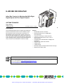
Artisan Technology Group is your source for quality
new and certified-used/pre-owned equipment
• FAST SHIPPING AND
DELIVERY
• TENS OF THOUSANDS OF
IN-STOCK ITEMS
• EQUIPMENT DEMOS
• HUNDREDS OF
MANUFACTURERS
SUPPORTED
• LEASING/MONTHLY
RENTALS
• ITAR CERTIFIED
SECURE ASSET SOLUTIONS
SERVICE CENTER REPAIRS
Experienced engineers and technicians on staff
at our full-service, in-house repair center
WE BUY USED EQUIPMENT
Sell your excess, underutilized, and idle used equipment
We also offer credit for buy-backs and trade-ins
www.artisantg.com/WeBuyEquipment
InstraView REMOTE INSPECTION
LOOKING FOR MORE INFORMATION?
Visit us on the web at www.artisantg.com for more
information on price quotations, drivers, technical
specifications, manuals, and documentation
SM
Remotely inspect equipment before purchasing with
our interactive website at www.instraview.com
Contact us: (888) 88-SOURCE | [email protected] | www.artisantg.com
IL MII BK DI8 DO4-PAC
I2
C
Inline Bus Coupler for Mechatrolink With Eight
Digital Inputs and Four Digital Outputs
PA
O4I8 D
K D 78696
II B
IL M -No.: 28
er
Ord
K
LIN
RO
AT
CH
ME
I1
O1
PWR
RX
TX
RN
UL D
M
US
UM
E
2
1
4
3
2
1
4
3
7
5
8
6
S1
AUTOMATIONWORX
Data Sheet
7358_en_00
X2
X1
© PHOENIX CONTACT - 08/2006
6
Description
The IL MII BK DI8 DO8-PAC bus coupler is the interface between the Mechatrolink and the Inline installation system.
Inline terminals can be connected in any location on a
Mechatrolink system using the bus coupler. The bus coupler and the Inline terminals form a station with local bus devices. The number of inline terminals allowed is determined
by the operating mode (17/32 byte) of the Mechatrolink network, as well as current limitations of the bus coupler.
Features
–
–
–
–
–
–
–
–
–
–
Mechatrolink network connection
Data transmission rate of 10 Mbps (MII)
and 4 Mbps (MI)
Supports a wide range of Inline terminals
Can be used in stand-alone mode - with no
Inline terminals
Complies with the Mechatrolink-II Intelligent I/O
specification
Supports “high speed“ I/O scanners
8 digital inputs
4 digital outputs
Electrical isolation of Mechatrolink interface and logic
Diagnostic and status LEDs
For additional information on the bus coupler, please refer to the user manual, see "Ordering Data" on page 2.
Make sure you always use the latest documentation.
It can be downloaded at www.download.phoenixcontact.com.
A conversion table is available on the Internet at
www.download.phoenixcontact.com/general/7000_en_00.pdf.
Artisan Technology Group - Quality Instrumentation ... Guaranteed | (888) 88-SOURCE | www.artisantg.com
IL MII BK DI8 DO4-PAC
Ordering Data
Bus Coupler
Description
Type
Order No.
Pcs./Pck.
Inline bus coupler for Mechatrolink with 8 digital inputs and 4 digital outputs
including end plate and connector
IL MII BK DI8 DO4-PAC
2884619
1
Pcs./Pck.
Accessories
Description
Type
Order No.
Connector set as replacement item
IL BK DIO-PLSET
2878599
1
Extended double signal connector for inputs,
4 signals with 3-wire connection method
IB IL SCN-12-ICP
2727611
10
Extended double signal connector for outputs,
4 signals with 3-wire connection method
IB IL SCN-12-OCP
2727624
10
Encoding profile
IL CP
2742683
100
Zack marker strip to label the terminals
ZB 6 ... see CLIPLINE catalog
1051003
10
DIN EN 50022 DIN rail, 2 meters
NS 35/7,5 PERFORATED
NS 35/7,5 UNPERFORATED
0801733
0801681
1
1
End clamp
CLIPFIX 35-5
3022276
50
Additional System Components
Description
Power supply units (INTERFACE catalog) for supplying the bus coupler
Documentation
Description
Type
Order No.
Pcs./Pck.
User manual:
Firmware Functions of the IL MII BK DI8 DO4-PAC Bus Coupler
UM EN IL MII BK DI8 DO4-PAC
2888961
1
User manual:
Automation Terminals of the Inline Product Range
IL SYS INST UM E
2698737
1
Application Note:
I/O Modules at Bus Couplers
AH IL BK IO LIST
9015358
1
7358_en_00
PHOENIX CONTACT
Artisan Technology Group - Quality Instrumentation ... Guaranteed | (888) 88-SOURCE | www.artisantg.com
2
IL MII BK DI8 DO4-PAC
Technical Data
General Data
Housing dimensions (width x height x depth)
80 mm x 121 mm x 70 mm
Weight
252 g (including connector)
Degree of protection
IP20 according to IEC 60529
Class of protection
Class 3, according to VDE 0106, IEC 60536
Response time (connected I/Os)
4 ms, typical
Connection method
Spring-cage terminals
solid/stranded 0.2 - 1.5 mm2
Sum of all I/O data per station
17 byte frame: 12 bytes of input data and 12 bytes of output data
32 byte frame: 27 bytes of input data and 32 bytes of output data
(per DIP switch setting)
System Data
Number of devices per station
63 maximum, but the I/O limits (above) should not be exceeded
Transmission rate on the local bus
500 kbps
Mechatrolink Interface
Data Rate
4 Mbps or 10 Mbps
Data Size
17 bytes or 32 bytes
Supply Voltage for UL, US, UM
Recommended cable lengths
30 m, maximum; do not route cables through outdoor areas
Continuation
Through potential routing
Nominal value
24 V DC
Permissible range (according to EN 61131-2)
19.2 V to 30 V (ripple included)
Safety equipment
Surge voltage, polarity reversal
Yes, suppressor diode parallel to supply voltage
Provide an external fuse for the 24 V area
This 24 V area must be externally protected. The power supply unit must be able to supply 4 times the nominal current of the external
fuse, to ensure that it trips in the event of an error.
The bus coupler supply UL (24 V) generates the analog supply UANA (24 V) and the communications power UL (7.5 V) for the Inline station.
Power Consumption
Current consumption from ULOGIC (7.5 V)
0.09 A with no inline terminals / 0.9 A, maximum
Maximum bus coupler current for supplying I/O terminal logic = 0.8 A maximum.
Current consumption from US (24 V)
8 A, maximum
Current consumption from UM (24 V)
8 A, maximum
Current consumption from UANALOG (24 V)
0.5 A, maximum
Power dissipation
2.16 W, typical / 4 W maximum
7358_en_00
PHOENIX CONTACT
Artisan Technology Group - Quality Instrumentation ... Guaranteed | (888) 88-SOURCE | www.artisantg.com
3
IL MII BK DI8 DO4-PAC
Digital Outputs
Number
4
Connection method for actuators
2 and 3-wire technology
Nominal output voltage UOUT
24 V DC
Differential voltage at Inom
<1V
Nominal current Inom per channel
0.5 A
Total current
2A
Nominal load
Ohmic
12 W
Lamp
12 W
Inductive
12 VA (1.2 H)
Switching frequency with nominal inductive load
0.5 Hz (1.2 H), maximum
Response time
1.2 ms, typical
Overload response
Auto restart
Response with inductive overload
Output may be damaged
Reverse voltage protection against short pulses
Protected against reverse voltages
Resistance to permanently applied reverse voltages
Protected against reverse voltages, permissible current 2 A, maximum
Response upon power down
The output follows the supply voltage without delay.
Limitation of the voltage induced on circuit interruption
-30.0 V, approximately
Safety equipment
Short circuit; overload
Type of safety equipment
Integrated free running circuit in the output chip
Maximum output current when switched off
10 µA
Error message to the higher-level control system
a short circuit causes a Peripheral Warning indication to the higher-level control system
When not loaded, a voltage can be measured even at an output that is not set.
Digital Inputs
Number
8
Connection method for sensors
2 and 3-wire technology
Input design
According to EN 61131-2 Type 1
Definition of switching thresholds
Maximum low-level voltage
ULmax < 5 V
Minimum high-level voltage
UHmin > 15 V
Common potentials
Sensor supply US, ground
Nominal input voltage UIN
24 V DC
Permissible range
-3 V < UIN < +30 V DC
Nominal input current for UIN
3 mA, typical
Current flow
Limited to a 3 mA, maximum
Delay time
1.2 ms, typical
Permissible cable length to the sensor
100 m
Use of AC sensors
AC sensors in the voltage range < UIN are limited in application
Safety equipment
Polarity reversal
Type of safety equipment
Serial diode for polarity reversal protection
Error message to the higher-level control system
Sensor supply not present
7358_en_00
PHOENIX CONTACT
Artisan Technology Group - Quality Instrumentation ... Guaranteed | (888) 88-SOURCE | www.artisantg.com
4
IL MII BK DI8 DO4-PAC
Ambient Conditions
Ambient temperature (operation)
0°C to +60°C
Ambient temperature (storage)
-25°C to +85°C
Humidity (operation/storage/transport)
95%, no condensation
In the range from -25°C to +60°C appropriate measures against increased humidity (> 85%) must be taken.
For a short period, slight condensation may appear on the outside of the housing if, for example, the terminal is brought into a closed room
from a vehicle.
Air pressure (operation/storage/transport)
70 kPa to 106 kPa (up to 3000 m above sea level)
Mechanical Requirements
Vibration test; sinusoidal vibrations according to IEC 60068-2-6; EN 600682-6
5g load, 2 hours in each space direction
Shock test according to IEC 60068-2-27; EN 60068-2-27
25g load for 11 ms, half sinusoidal wave,
three shocks in each space direction and orientation
Conformance With EMC Directive 89/336/EEC
Noise Immunity Test According to EN 61000-6-2
Electrostatic discharge (ESD)
EN 61000-4-2/
IEC 61000-4-2
Criterion B
6 kV contact discharge
8 kV air discharge
Electromagnetic fields
EN 61000-4-3
IEC 61000-4-3
Criterion A
Field strength: 10 V/m
Fast transients (burst)
EN 61000-4-4/
IEC 61000-4-4
Criterion A
All interfaces: 1 kV
Criterion B
All interfaces: 2 kV
Surge voltage
EN 61000-4-5/
IEC 61000-4-5
Criterion B
DC supply lines:
0.5 kV / 1 kV (symmetrical / asymmetrical)
Fieldbus cable shielding 1 kV
Conducted interference
EN 61000-4-6
IEC 61000-4-6
Criterion A
Test voltage 10 V
Noise Emission Test According to EN 61000-6-4
Noise emission of housing
EN 55011
Class A
Approvals
Information on current approvals can be found on the Internet at www.phoenixcontact.com.
7358_en_00
PHOENIX CONTACT
Artisan Technology Group - Quality Instrumentation ... Guaranteed | (888) 88-SOURCE | www.artisantg.com
5
IL MII BK DI8 DO4-PAC
Local Diagnostic and Status Indicators
Mechatrolink
PWR
PWR
I2
TX RX
UL RN
US MD
UM
PAC
O4I8 D
K D 78696
II B
IL M -No.: 28
er
Ord
ME
C
O
TR
HA
LIN
I1
K
5 6
7 8
I2
O1
PWR
RX
TX
RN
UL D
M
US
UM
E
2
1
4
3
I1
S1
1 2
3 4
O1
X2
X1
I1
E
1 2
3 4
Figure 1
I2
7
5
8
6
2
1
4
3
O1
7358A005
Indicators on the bus coupler
LED
Color
Meaning
State
UL
Green
ULogic
ON
24 V bus coupler power supply /
7.5 communications power present
OFF
24 V bus coupler power supply /
7.5 communications power not present
ON
24 V segment circuit supply present
OFF
24 V segment circuit supply not present
ON
24 V I/O supply present
OFF
24 V I/O supply not present
US
UM
TX
Green
Green
Yellow
USegment
UMain
Transmit
data
Continuous
flashing
OFF
RX
Yellow
Receive
Data
Continuous
flashing
OFF
7358_en_00
Description of the LED States
Mechatrolink protocol chip is actively transmitting.
Mechatrolink protocol chip is not actively transmitting.
Mechatrolink protocol chip is actively receiving.
Mechatrolink protocol chip is not actively receiving.
PHOENIX CONTACT
Artisan Technology Group - Quality Instrumentation ... Guaranteed | (888) 88-SOURCE | www.artisantg.com
6
IL MII BK DI8 DO4-PAC
LED
Color
Meaning
State
Description of the LED States
RN
Green/
red
Local bus
status
OFF
Stand-alone mode
Onboard I/Os are used.
No other Inline terminals connected.
Green ON
Local bus communication is active.
Continuous
flashing, green
1 green flash
Peripheral Warning: An output may be shorted.
2 green flashes
I/O Size Warning:
The amount of Inline local bus data exceeds the frame-size DIP
switch setting. Communication continues. Only frame-size bytes
of I/O data are accessible.
3 green flashes
Operation with error data
Red ON
7358_en_00
Initialization/configuration phase
Module Connection Alarm: Local bus is stopped
2 red flashes
Module Change Alarm On Startup:
Inline configuration is incorrect on startup.
2 red flashes,
then 1 green
flash
Module Change Alarm On Startup:
Inline configuration error when starting the bus coupler:
Onboard I/Os are operated with error data.
2 red flashes,
then 2 green
flashes
Module Change Alarm On Startup:
Inline configuration error when starting the bus coupler:
Onboard I/Os and Inline I/Os are operated with error data.
3 red flashes
Module Change Alarm While Running:
Inline configuration becomes incorrect while running (Inline terminal failed).
3 red flashes,
then 1 green
flashes
Module Change Alarm While Running:
Inline configuration becomes incorrect while running (Inline terminal failed). Onboard I/O running error data.
3 red flashes,
then 2 green
flashes
Module Change Alarm While Running:
Inline configuration becomes incorrect while running (Inline terminal failed). Onboard and Inline I/O running error data.
PHOENIX CONTACT
Artisan Technology Group - Quality Instrumentation ... Guaranteed | (888) 88-SOURCE | www.artisantg.com
7
IL MII BK DI8 DO4-PAC
LED
Color
Meaning
State
Description of the LED States
MD
Green/
red
Network status
OFF
No voltage present.
Green ON
Continuous
flashing, green
E
1-4
1-8
Red
Yellow
Yellow
Error
O1
I1, I2
Phase 2:
Network connected. Asynchronous communication activated.
Phase 1:
Initializing or bus coupler waiting for master to connect.
3 green Flashes
The master has tried to set a transmission cycle time that is not
supported.
Red ON
Communication Alarm:
Loss of communication with the master. All outputs are set according to DIP switch 9.
Continuous
flashing, red
Power-Loss Alarm:
One of the power supplies has failed. The outputs are set according to the current Recover Mode, see note below.
2 red flashes
Communication Alarm:
Mechatrolink Communication Alarm with frame errors occurring
at the time of the alarm. All outputs are set according to DIP
switch 9.
3 red flashes
Initialization of the Mechatrolink protocol chip has failed.
ON
Peripheral Warning for the onboard outputs
OFF
Peripheral Warning not present.
ON
Outputs active
OFF
Outputs not active
ON
Inputs active
OFF
Inputs not active
If the US power supply fails and the fault recover mode is such that outputs are to be set with error data, the
LEDs of the output terminals may be on while the actual output may be off.
7358_en_00
PHOENIX CONTACT
Artisan Technology Group - Quality Instrumentation ... Guaranteed | (888) 88-SOURCE | www.artisantg.com
8
IL MII BK DI8 DO4-PAC
Circuit Diagram
MII
IB
µP
5V
7.5V
U L+
DO1...4
B
RS
485
DI1...8
UANA
UL
3.3V
7.5V
A
8x DI
7.5V
24V
24V
24V
C
4x
DO
US
UM
UL
US
US
UM
MECHATROLINK
PWR
7358A003
Figure 1
Circuit diagram of the bus coupler
Key:
MII
Protocol chip
The gray areas in the circuit diagram represent the electrically isolated areas:
µ P
Microprocessor
IB
Protocol chip
A: Mechatrolink interface
B: Logic
C: I/O
Optocoupler
Power supply unit with electrical isolation
R S
4 8 5
RS-485 interface
Transformer
7358_en_00
PNP transistor
PHOENIX CONTACT
Artisan Technology Group - Quality Instrumentation ... Guaranteed | (888) 88-SOURCE | www.artisantg.com
9
IL MII BK DI8 DO4-PAC
Connecting the Mechatrolink Network
Connect the Mechatrolink network to X1 and X2.
Pin Assignments of the Mechatrolink Connectors X1
and X2
I2
PAC
O4I8 D
K D 78696
II B
IL M -No.: 28
er
Ord
ME
CH
R
AT
O
K
LIN
I2
I1
O1
PWR
RX
TX
RN
UL D
M
US
M
U
E
2
1
4
3
2
1
4
3
7
5
8
6
4-PA
DO
DI8 696
II BK 78
IL M -No.: 28
er
Ord
ME
S1
R
AT
CH
OL
C
I1
O1
INK
PWR
RX
RN
UL D
M
US
UM
TX
E
2
1
4
3
2
1
4
3
DATA
DATA
X2
X2
X1
X1 X2
Figure 2
1
1
2
2
3
3
4
4
(NC)
DATA
DATA
SH
7357A006
Connecting the Mechatrolink network
On the last bus coupler in the Mechatrolink network a termination resistor must be inserted on
the Mechatrolink interface.
7358_en_00
SH
X1
X2
X1
(NC)
S1
7
5
8
6
7358A007
Figure 3
Pin assignments of the mechatrolink connectors
Pin
Assignment
1
Not connected
2
DATA
3
DATA
4
Shield
PHOENIX CONTACT
Artisan Technology Group - Quality Instrumentation ... Guaranteed | (888) 88-SOURCE | www.artisantg.com
10
IL MII BK DI8 DO4-PAC
Example Topology
IL M II B K D I8 D O 4 -P A C
M E C H A T R O L IN K
IL M II B K D I8 D O 4 -P A C
M E C H A T R O L IN K
1
2
1
2
5
7
3
4
3
4
6
8
S 1
M
S
S
X 1
1
2
1
2
5
7
3
4
3
4
6
8
S 1
X 2
X 1
X 2
S
T
T
7 3 5 8 A 0 0 6
Figure 4
Example Topology
Notes:
M: Master, a network control station. Each network must have at least one master.
S: Slave Device, a device such as a IL MII BK DI8 DO4-PAC or servo amplifier. The master controls the slave
devices though the network. Multiple IL MII BK DI8 DO4-PAC bus couplers may be located on the same network.
T: Terminating Resister (130 Ω located at both ends of the bus)
Configuration Using the DIP Switches
I1
O1
O
K
LIN
RO
AT
CH
ME
PWR
RX
TX
RN
UL D
M
US
UM
D
E
2
1
4
3
2
1
4
3
7
5
8
6
Baud
Data
S1
Fault
Confg
On
I2
C
4-PA
DO
DI8 696
II BK 78
IL M -No.: 28
rder
1 2 3 4 5 6 7 8 9 10
Adress Bits
The DIP switches are on the left side of the bus coupler.
The following functions can be set using the DIP
switches.These functions only take effect when the bus
coupler is powered-on.
1
2
4
8
16
10/4 MBd
17/32 Byte
Reserved
Off/Hold
Savd/Auto
X2
X1
7357A003
Figure 5
7358_en_00
DIP switches
PHOENIX CONTACT
Artisan Technology Group - Quality Instrumentation ... Guaranteed | (888) 88-SOURCE | www.artisantg.com
11
IL MII BK DI8 DO4-PAC
Switch
1 to 5
6
7
8
9
10
Meaning
Slave address:
Switches 1 to 5 represent a binary number. Switch 1 is the least significant bit. The switch setting is added to
60hex in order to create the slave’s Mechatrolink network address.
Bus speed:
Off = 10 Mbps (MII), On = 4 Mbps (MI)
Frame size:
Off = 17 bytes (supported in both bus speeds)
On = 32 bytes (only supported by bus speed = 10 Mbps)
This switch is ignored when switch 6 is on.
Reserved
Communication Loss Output Action:
When communication with the master is lost, or the master sends a DISCONNECT command.
Off = outputs are set to 0.
On = outputs retain last value.
Automatic configuration:
Off = Use the Inline bus configuration stored last. An alarm is indicated if the current bus configuration is not
the same as the previous configuration.
On = Auto configure the local bus and save it in non-volatile memory. Select Stand-alone mode, if no Inline
terminals are connected to the bus coupler.
Proceed as follows:
•
Disconnect the voltage from the bus coupler.
•
Add/remove the Inline terminals, if necessary.
•
Set switch 10 on.
•
Apply voltage to the bus coupler.
•
Set switch 10 off.
After automatic configuration switch 10 should be switched off.
1 to 10
Factory Defaults:
If voltage is connected to the bus coupler and all the switches are on, all non-volatile memory parameters (except for serial number) will return to their factory default values on the next power-up. The FAC_DEFAULTS
bit of the IL_CTRL byte can also be used for this purpose. Proceed as follows:
•
Disconnect the voltage from the bus coupler.
•
Set all switches on.
•
Apply voltage to the bus coupler. The RN LED and MD LED are red to indicate that the bus coupler is ready
to be reset.
•
Disconnect the voltage from the bus coupler.
•
Set switch 10 on and set all the other switches to the relevant settings.
•
Apply voltage to the bus coupler. It will start up with factory default values.
•
Set switch 10 off.
After automatic configuration switch 10 should be switched off.
7358_en_00
PHOENIX CONTACT
Artisan Technology Group - Quality Instrumentation ... Guaranteed | (888) 88-SOURCE | www.artisantg.com
12
IL MII BK DI8 DO4-PAC
Terminal Point Assignment
1.1
1.2
1.3
1.4
Terminal point assignment of the power connector (1)
PWR
O1
I1
I2
1.1 2.1
1.1 2.1
1.1 2.1
3.1 4.1
1
1
1.2 2.2
2
2
1.3 2.3
3
3
1.4 2.4
4
4
2.1
1.1
2.2
1.2
2.3
2.4
1.3
1.4
1
1
1
1.2 2.2
2
2
1.3 2.3
1.4 2.4
2.2
1.2
2.4
4
4
1.1
2.3
3
3
2.1
1.3
1.4
1
1
1.2 2.2
2
2
1.3 2.3
3
3
1.4 2.4
4
4
2.1
3.1
2.2
3.2
2.3
2.4
3.3
3.4
3
2
1
1
3.2 4.2
2
2
3.3 4.3
3
3
3.4 4.4
4
4
Terminal
Points
Assignment
Terminal
Points
Assignment
4.1
1.1
US
2.1
UM
4.2
1.2
UL
2.2
UM
4.3
1.3
GND UL
2.3
GND UM, US
4.4
1.4
Functional
earth ground
(FE)
2.4
Functional
earth ground
(FE)
4
71820010
Figure 6
PWR DO4 DI4
1
2
3
DI4
4
US UM
UL
IN6
+24 V
+
-
+24 V
UM
OUT3
OUT2
7358A002
Connection example
Connect the bus coupler according to Figure 7.
7358_en_00
Terminal
Points
Assignment
Terminal
Points
Assignment
1.1
OUT1
2.1
OUT2
1.2
PGND
2.2
PGND
1.3
FE
2.3
FE
1.4
OUT3
2.4
OUT4
Terminal point assignment of the input connector (3)
IN7
+
Mechatrolink
network
X2
-
X1
Figure 7
Terminal point assignment of the output connector (2)
Terminal point assignment for the connectors
Terminal
Points
Assignment
Terminal
Points
Assignment
1.1
IN1
2.1
IN2
1.2
US
2.2
US
1.3
PGND
2.3
PGND
1.4
IN3
2.4
IN4
Terminal point assignment of the input connector (4)
Terminal
Points
Assignment
Terminal
Points
Assignment
3.1
IN5
4.1
IN6
3.2
US
4.2
US
3.3
PGND
4.3
PGND
3.4
IN7
4.4
IN8
PHOENIX CONTACT
Artisan Technology Group - Quality Instrumentation ... Guaranteed | (888) 88-SOURCE | www.artisantg.com
13
IL MII BK DI8 DO4-PAC
Process Data
Assignment of Terminal Points to the
OUT Process Data (Slot 2)
(Byte.Bit) Byte
view
Bit
Module
Byte 4
7
6
Slot
Terminal
point
(signal)
5
4
3
2
1
0
2
2.4 1.4 2.1 1.1
Terminal
2.2 1.2 2.2 1.2
point (GND)
not used
Terminal
2.3 1.3 2.3 1.3
point (FE
connection)
Status
indicator
Slot
LED
2
4
3
2
1
-
-
-
-
2
1
0
Assignment of Terminal Points to the
IN Process Data (Slots 3 and 4)
(Byte.bit) Byte
view
Bit
Module
Byte 4
7
6
Slot
Terminal
point
(signal)
5
4
3
4
3
4.4 3.4 4.1 3.1 2.4 1.4 2.1 1.1
Terminal
4.2 3.2 4.2 3.2 2.2 1.2 2.2 1.2
point (24 V)
Terminal
4.3 3.3 4.3 3.3 2.3 1.3 2.3 1.3
point (GND)
Status
indicator
Slot
LED
4
8
7
3
6
5
4
3
2
1
Further additional information please refer to
the user manual, chapter "Mappings Reference".
© PHOENIX CONTACT 08/2006
7358_en_00
PHOENIX CONTACT GmbH & Co. KG • 32823 Blomberg • Germany
Phone: +49-(0) 5235-3-00 • Fax: +49-(0) 5235-3-4 12 00 • www.phoenixcontact.com
www.phoenixcontact.com/salesnetwork
Artisan Technology Group - Quality Instrumentation ... Guaranteed | (888) 88-SOURCE | www.artisantg.com
14
Artisan Technology Group is your source for quality
new and certified-used/pre-owned equipment
• FAST SHIPPING AND
DELIVERY
• TENS OF THOUSANDS OF
IN-STOCK ITEMS
• EQUIPMENT DEMOS
• HUNDREDS OF
MANUFACTURERS
SUPPORTED
• LEASING/MONTHLY
RENTALS
• ITAR CERTIFIED
SECURE ASSET SOLUTIONS
SERVICE CENTER REPAIRS
Experienced engineers and technicians on staff
at our full-service, in-house repair center
WE BUY USED EQUIPMENT
Sell your excess, underutilized, and idle used equipment
We also offer credit for buy-backs and trade-ins
www.artisantg.com/WeBuyEquipment
InstraView REMOTE INSPECTION
LOOKING FOR MORE INFORMATION?
Visit us on the web at www.artisantg.com for more
information on price quotations, drivers, technical
specifications, manuals, and documentation
SM
Remotely inspect equipment before purchasing with
our interactive website at www.instraview.com
Contact us: (888) 88-SOURCE | [email protected] | www.artisantg.com