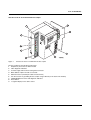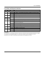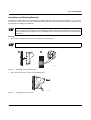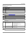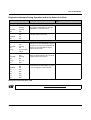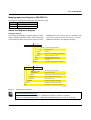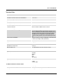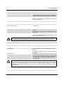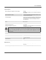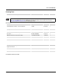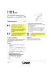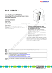
1
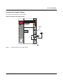
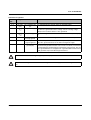
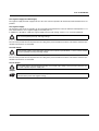
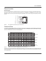
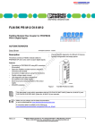
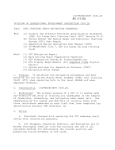
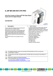
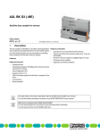
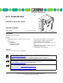
FL IL 24 BK-PN-PAC
ETHERNET
PROFINET IO/Inline Bus Coupler
AUTOMATIONWORX
Data Sheet
© PHOENIX CONTACT - 07/2005
Description
PROFINET IO/Inline bus coupler
Features
–
–
PROFINET IO/Inline bus coupler for the Inline I/O system
Ethernet TCP/IP
- 100BASE-TX
- Management via SNMP
- Integrated web server
–
–
–
–
–
Up to 63 other Inline modules can be connected, of
which a maximum of eight can be PCP devices
Flexible installation system for Ethernet
Representation of process data in the browser using
XML
Supported protocols: TCP/UDP, SNMPv2, TFTP and
ICMP (Ping), PROFINET IO
Comprehensive system diagnostics
Application
Connection of sensors/actuators via PROFINET.
Quick Start Guides for PC WorX 5 and Siemens S7 can be found in the Download Center at
www.download.phoenixcontact.com.
PC WorX: "Quick Start Guide PC WorX 5" (UM QS EN PC WORX 5, Order No. 26 99 86 2)
Siemens S7: "Quick Start Guide STEP 7" (UM QS EN PROFINET PROXY IB, Order No. 26 99 99 8)
Make sure you always use the latest version of the GSDML file and the latest documentation for the module.
The latest GSDML files and documentation can be found on the Internet at
www.download.phoenixcontact.com in the Download Center.
Ensure that you are always working with the most recently published documentation.
It can be downloaded at www.download.phoenixcontact.com.
A conversion table is available on the Internet at
www.download.phoenixcontact.com/general/7000_en_00.pdf.
7149_en_00
PHOENIX CONTACT GmbH & Co. KG • Flachsmarktstraße 8 • 32825 Blomberg • Germany
Phone: +49-(0) 5235-3-00 • Fax: +49-(0) 5235-3-4 12 00 • www.phoenixcontact.com
www.phoenixcontact.com/salesnetwork
1
FL IL 24 BK-PN-PAC
General Information
Warning
Disregarding this warning may result in damage to equipment and/or serious personal injury. Only qualified personnel may start up and operate these devices. According to the safety instructions in this text, qualified personnel are persons who are authorized to start up, to ground, and to mark devices, systems, and equipment
according to the standards of safety technology. In addition, these persons must be familiar with all warning
instructions and maintenance measures in this text.
Warning
The FL IL 24 BK-PN-PAC module is designed exclusively for SELV operation according to IEC 60950/
EN 60950/VDE 0805.
Shielding
The shielding ground of the connected twisted pair cables is electrically connected to the female connector.
When connecting network segments, avoid ground loops, potential transfers, and voltage equalization currents
using the braided shield.
Electrostatic discharge
The module contains components that can be damaged or destroyed by electrostatic discharge. When handling the module, observe the necessary safety precautions against electrostatic discharge (ESD) according
to EN 61340-5-1 and EN 61340-5-2 .
Housing
Only authorized Phoenix Contact personnel are permitted to open the housing.
7149_en_00
PHOENIX CONTACT
2
FL IL 24 BK-PN-PAC
Structure of the FL IL 24 BK-PN-PAC Bus Coupler
ETHERNET
Figure 1
Structure of the FL IL 24 BK-PN-PAC bus coupler
The bus coupler has the following components:
1 End plate to protect the last Inline module
2 Inline diagnostic indicators
3 24 V DC supply and functional earth ground connector
4 MAC address in plain text and as a barcode
5 Ethernet interface (twisted pair cables in RJ45 format)
6 Two PE contacts for grounding the bus coupler using a DIN rail (on the back of the module)
7 PROFINET/Ethernet status and diagnostic indicators
8 Reset button
9 7-segment display for the device status
7149_en_00
PHOENIX CONTACT
3
FL IL 24 BK-PN-PAC
Local Status and Diagnostic Indicators
Des.
Color
Status
Electronics Module
UL
Green
ON
OFF
UM
Green
ON
OFF
US
Green
ON
OFF
Ethernet Port
SF
Red
ON
OFF
BF
Red
ON
Flashing
COL
Red
XMT
Green
RCV
Yellow
LNK
Green
OFF
ON
OFF
ON
OFF
ON
OFF
ON
OFF
Meaning
24 V supply, 7 V communications power/interface supply in the tolerance range
24 V supply, 7 V communications power/interface supply not in the tolerance range
Voltage is present in the main circuit (+24 V DC)
Voltage is not present in the main circuit
24 V segment supply is present
24 V segment supply is not present
System error present (incorrect parameterization, bus error, peripheral fault)
No system error, INTERBUS running without errors
No link status available
Link status available, no communication connection to the IO controller, connection establishment is currently active
The IO controller has established an active communication connection to the IO device
Collision of data telegrams
Transmission of telegrams without a collision (if LNK LED active)
Data telegrams are being sent
Data telegrams are not being sent
Data telegrams are being received
Data telegrams are not being received
Physical network connection ready to operate
Physical network connection interrupted or not present
Reset Button
The reset button is on the front plate. When the reset button is pressed the Inline masterboard and the Ethernet adapter
are completely reset and initialized (selftest, etc.). Inline system outputs are reset and inputs are not read.
Following reset, the module is automatically started up again by the PROFINET IO controller.
7149_en_00
PHOENIX CONTACT
4
FL IL 24 BK-PN-PAC
Installation and Mounting/Removal
Install the FL IL 24 BK-PN-PAC on a clean DIN rail according to EN 60715 (Phoenix Contact: item NS 35...). To avoid contact resistance only use clean, corrosion-free DIN rails. End clamps must be mounted on both sides of the module to stop
the terminals from slipping on the DIN rail.
The functional earth ground must be connected to the 24 V DC supply/functional earth ground connection. The
contacts are directly connected to the potential jumper and FE springs on the bottom of the housing. The coupler is grounded when it is snapped onto a grounded DIN rail. Functional earth ground is only used to discharge
interference.
Mounting
1.
First, snap all required electronics bases vertically onto the DIN rail (A).
Ensure that all featherkeys and keyways on adjacent terminals are interlocked (B).
A1
B1
6 1 5 5 0 0 0 5
Figure 2
2.
Snapping on the electronics base
Next, attach the connectors to the corresponding bases.
12
1
6 1 5 5 0 0 0 6
Figure 3
7149_en_00
Plugging in the I/O connector
PHOENIX CONTACT
5
FL IL 24 BK-PN-PAC
Connecting the Supply Voltage
The module is operated using a +24 V DC SELV.
Typical Connection of the Supply Voltage
US
UM
RESET
FL IL 24 BK-PN-PAC
Ord.-No.: 2878816
UL
Internal
jumper
SF
BF
1
2
00.A0.45.50.A1.77
COL
1
1
2
2
3
3
4
4
+
XMT
RCV
LNK
10/100
+
UL
-
+
-
UM
-
US
714900003
Figure 4
7149_en_00
Typical connection of the supply voltage
PHOENIX CONTACT
6
FL IL 24 BK-PN-PAC
Connector Assignment
Terminal
Assignment
Point
Connector Power Connector
1.1
24 V DC 24 V segment supply
(US)
1.2
24 V DC 24 V power supply
(UL)
2.1, 2.2
24 V DC
(UM)
Main voltage
1.3
LGND
2.3
SGND
1.4, 2.4
FE
Reference potential logic ground
Reference potential
segment ground
Functional earth
ground (FE)
Remark
The supplied voltage is directly led to the potential jumper.
The communications power for the bus coupler and the connected local
bus devices is generated from this voltage. The 24 V analog voltage
(UANA) for the local bus devices is also generated.
The main voltage is routed to the local bus devices via the potential jumpers.
The potential is the reference ground for the communications power.
The reference potential is directly led to the potential jumper and is, at the
same time, ground reference for the main and segment supply.
The functional earth ground must be connected to the 24 V DC supply/
functional earth ground connection. The contacts are directly connected to
the potential jumper and FE springs on the bottom of the housing. The coupler is grounded when it is snapped onto a grounded DIN rail. Functional
earth ground is only used to discharge interference.
The maximum total current flowing through the potential jumpers is 8 A.
The functional earth ground must be connected through the 24 V DC supply/functional earth ground connection.
7149_en_00
PHOENIX CONTACT
7
FL IL 24 BK-PN-PAC
24 V Segment Supply/24 V Main Supply
The segment supply and main supply must have the same reference potential. An electrically isolated architecture is not
possible.
24 V Segment Supply
An emergency stop circuit, for example, can be connected and switched on the connector between terminal points 1.1/2.1.
This means that there is no segment supply via terminal point 1.1.
In addition, it is possible to supply the segment supply from the main voltage. For this, 1.1/2.1 must be jumpered.
The 24 V segment supply is protected against polarity reversal (inverse-parallel diode -> causes a short circuit
in the event of polarity reversal) and surge voltage.
It does not have short-circuit protection.
The user must provide short-circuit protection. The rating of the preconnected fuse must be such that the maximum permissible load current is not exceeded.
24 V Main Supply
The 24 V main supply is protected against polarity reversal (inverse-parallel diode -> causes a short circuit in
the event of polarity reversal) and surge voltage.
It does not have short-circuit protection.
The user must provide short-circuit protection. The rating of the preconnected fuse must be such that the maximum permissible load current is not exceeded.
24 V BK Supply
The 24 V BK supply is protected against polarity reversal and surge voltage. These protective elements are
only used to protect the power supply unit.
Jumpers
Terminals 1.3 and 2.3 on the connector can be jumpered if the same reference potential is to be used for the
communications power and segment voltage.
7149_en_00
PHOENIX CONTACT
8
FL IL 24 BK-PN-PAC
Ethernet Connection
Ethernet Interface
The FL IL 24 BK-PN-PAC has an Ethernet interface on the front in RJ5 format, to which only a twisted pair cable with an
impedance of 100 Ω can be connected. The data transmission rate is 100 Mbps. The 100BASE-TX port of the bus coupler
can detect a pair of incorrectly connected receiving cables (RD+/RD-) and correct them using the auto polarity correction
function.
Figure 5
n .c .
P in 8
n .c .
P in 7
T D -
P in 6
n .c .
P in 5
n .c .
P in 4
T D +
P in 3
R D -
P in 2
R D +
P in 1
R J 4 5
Pin assignment of the Ethernet port in RJ45 format
Transfer of I/O Data
The I/O data of individual Inline modules is transferred via memory areas organized in a word-oriented way (separate memory areas for input and output data). The Inline modules use the memory according to their process data width. The assignment of the individual bits is shown in the following diagram:
B it 1 5
B it 1
2 w o rd s
1 w o rd
1 b y te
4 b its
2 b its
6 1 5 5 0 0 0 7
Figure 6
Position of the user data for individual devices in the word array
To achieve cycle consistency between I/O data and the station bus cycle, the bus coupler uses an exchange buffer mechanism. This mechanism ensures that the required I/O data is available on time and is protected by appropriate measures
when writing/reading.
7149_en_00
PHOENIX CONTACT
9
FL IL 24 BK-PN-PAC
The following diagram shows the position of the user data for several devices in the word array.
1 5
0 1 5
B y te d e v ic e
0 1 5
4 - b it d e v ic e
0
2 - b it d e v ic e
6 1 5 5 0 0 0 8
Figure 7
7149_en_00
Position of the user data for several devices in the word array
PHOENIX CONTACT
10
FL IL 24 BK-PN-PAC
Meaning of the 7-Segment Display
During Startup/Operation
Display
01
Meaning
Boot Loader is started
bo
02
Firmware is extracted
Firmware is started
__
--
Initializing the PROFINET IO stack
Operation
SL alternating Malfunction in the INTERBUS network
with xx
00 alternating PROFINET device ID
with -During Firmware Update
An application note for firmware update via TFTP (AH EN TFTP FIRMWARE UPDATE) can be found in the
Download Center at www.download.phoenixcontact.com.
Display
Meaning
03
04
Firmware is requested to download at TFTP server
The firmware is downloaded to the memory
05
The firmware transfer to the memory is complete
In the event of a System Fail (SF), the slot number is indicated on the 7-segment display. Example: Error at
slot 3. Display: "SL" alternating with "03" in the second clock.
Boot Loader Error Messages
Display
17
19
Meaning
The transfer of the firmware failed
during TFTP download (display
changes from "03" to "17")
Remedy
– Check the physical connection
– Establish a point-to-point connection
– Make sure that the file (with the specified file name) exists and
is in the correct directory
– Check the IP address of the TFTP server
– Activate the TFTP server
– Repeat the download
The TFTP download was completed – Provide a valid firmware version with the previously specified file
successfully, but the file is not a valid
name
firmware version for the bus coupler – Repeat the download
The points under "Remedy" are recommendations; they do not all have to be carried out for every error.
7149_en_00
PHOENIX CONTACT
11
FL IL 24 BK-PN-PAC
Startup
Make sure you always use the latest version of the GSDML file and the latest documentation for the module.
The latest GSDML files and documentation can be found on the Internet at
www.download.phoenixcontact.com in the Download Center.
Quick Start Guides for PC WorX 5 and Siemens S7 can be found in the Download Center at
www.download.phoenixcontact.com.
PC WorX: "Quick Start Guide PC WorX 5" (UM QS EN PC WORX 5, Order No. 26 99 86 2)
Siemens S7: "Quick Start Guide STEP 7" (UM QS EN PROFINET PROXY IB, Order No. 26 99 99 8)
Starting the Firmware
The firmware is started once the device has been connected to the power supply or the reset button has been pressed. The
following sequence is displayed:
Display
Meaning
01
bo
Boot Loader is started
Firmware is extracted
02
__
Firmware is started
Initializing the PROFINET IO stack
--
Operation
Update Rate
The minimum update rate is 4 ms. Always set an update
rate higher than the bus cycle time. The bus cycle time can
be read using DIAG+ or PC WorX.
7149_en_00
PHOENIX CONTACT
12
FL IL 24 BK-PN-PAC
Diagnostic Indicators During Operation and in the Event of an Error
LED
Meaning
Measure/Remedy in the Event of an
Error
States During Operation:
SF
OFF
PROFINET IO device waiting for communication with the PROFINET IO controller.
BF
Flashing
INTERBUS is not parameterized.
RDY/RUN
Flashing
FAIL
OFF
SF
OFF
PROFINET IO controller established communication without any errors.
BF
OFF
RDY/RUN
ON
FAIL
OFF
States in the Event of an Error:
SF
ON
PROFINET IO controller was parameter- Check parameterization and correct.
ized
incorrectly. The INTERBUS configuraBF
OFF
tion
that
was sent from the PROFINET IO
RDY/RUN
Flashing
controller to the PROFINET IO device
FAIL
ON
could not be executed.
Display
SL alternating
with 01
SF
ON
INTERBUS errors during operation
There is a bus error or peripheral fault.
BF
OFF
Diagnostic display indicates the slot (SL alRDY/RUN
Flashing
ternating with the slot number).
FAIL
ON
Display
02 ... xx
FAIL
OFF
SF
OFF
The physical communication connection
Restore the physical connection.
was interrupted, the PROFINET IO controlBF
ON
ler can no longer be reached. No link.
RDY/RUN
ON
FAIL
COL
XMT
RCV
Link
OFF
OFF
OFF
OFF
OFF
Management Information Base - MIB
The latest MIBs can be found on the Internet at www.download.phoenixcontact.com.
7149_en_00
PHOENIX CONTACT
13
FL IL 24 BK-PN-PAC
Mapping Inputs and Outputs to PROFINET IO
The module is assigned the following input and output data words:
Slot
Slot 0
Slot 1
Data Length
4 words IN/4 words OUT
Status and Diagnostic Register
Diagnostic Register
The controller board diagnostic registers (diagnostic status
register, diagnostic parameter register, and extended diagnostic parameter register) represent the current state of the
n + 1
n
0 7
7
6
5 4
3
2 1
0
U S E R
P F
C T R L
B u s e rro r
F a u lt o n th e c o n tr o lle r b o a r d /h a r d w a r e
D E T E C T
D ia g n o s tic r o u tin e is a c tiv e
R U N
A C T IV E
D a
S e
to
C o
R E A D Y
n
6
5 4
U s e r e r r o r /p a r a m e te r iz a tio n
P e r ip h e r a l fa u lt
B U S
7
INTERBUS system for the user. Thus, it is possible to indicate the state of the bus system, error causes, as well as
additional information to the application program.
ta tr a n s m is s io n is a c tiv e
le c te d c o n fig u r a tio n is r e a d y
o p e ra te
n tr o lle r b o a r d is r e a d y to o p e r a te
n + 1
3 2
1
0 7
B
B A S
C L A
R E S U
S A
P /S Y S _ F A IL /
B /S T O P
L T
S Y -R E S U L T
D C -R E S U L T
W A R N IN G
Q U A L IT Y
S D S I
0
B u s s e g m e n t d is c o n n e c te d
O u tp u ts w e re re s e t
S ta n d a r d fu n c tio n p r o c e s s e d n e g a tiv e ly
S y n c h r o n iz a tio n e r r o r o c c u r r e d
F a u lty d a ta c y c le s
D e fin e d w a r n in g tim e e x c e e d e d
D e fin e d e r r o r d e n s ity e x c e e d e d
M e s s a g e to c o n tro l s y s te m
p re s e n t
5 1 5 0 C 0 0 3
Figure 8
Diagnostic Status Register
Quick Start Guides for PC WorX 5 and Siemens S7 can be found in the Download Center at
www.download.phoenixcontact.com.
PC WorX: "Quick Start Guide PC WorX 5" (UM QS EN PC WORX 5, Order No. 26 99 86 2)
Siemens S7: "Quick Start Guide STEP 7" (UM QS EN PROFINET PROXY IB, Order No. 26 99 99 8)
7149_en_00
PHOENIX CONTACT
14
FL IL 24 BK-PN-PAC
Parameterization
PC WorX
PC WorX Version 5.0 or later is required to parameterize
the PROFINET IO devices. An online data sheet with important technical data and a configuration file is integrated
into PC WorX. If several versions of the configuration file
are available, make sure that the file version used corresponds to the firmware/hardware version used.
Other Tools
The PROFINET IO device is parameterized using the configuration tool of the PROFINET IO controller. To do this, integrate the appropriate GSDML file of the device into the
corresponding software tool (STEP 7/hardware configuration, etc.). Make sure that the file version used corresponds
to the firmware/hardware version used.
The latest version of the GSDML file can be
downloaded at
www.download.phoenixcontact.com.
Parameters:
Slot 0: Diagnostic alarm (active (default)/inactive)
PROFINET IO enables the PROFINET IO device to store
diagnostic information with the error location and error type.
The PROFINET IO controller is informed that a diagnosis
has been received via an incoming alarm. Alarms are only
sent if they were enabled via parameters during startup.
If the diagnosis has been removed, an outgoing alarm is
sent to the controller.
If at least one diagnosis is stored, the SL LED lights up. If
no diagnoses are present, the SL LED is not active.
Bus errors are indicated with higher priority in the display
than peripheral faults.
7149_en_00
PHOENIX CONTACT
15
FL IL 24 BK-PN-PAC
Technical Data
General Data
Function
Housing dimensions (width x height x depth)
Permissible operating temperature (EN 60204-1)
Permissible storage temperature (EN 60204-1)
Degree of protection
Class of protection
Humidity (operation) (EN 60204-1)
Humidity (storage) (EN 60204-1)
Air pressure (operation)
Air pressure (storage)
Preferred mounting position
Connection to protective earth ground
Resistance to solvents
Weight
PROFINET IO/Inline bus coupler
90 mm x 72 mm x 116 mm
0°C to +55°C
-25°C to +85°C
IP20, DIN 40050, IEC 60529
Class 3 VDE 0106; IEC 60536
5% to 90%, no condensation
5% to 95%, no condensation
80 kPa to 108 kPa, 2000 m above sea level
70 kPa to 108 kPa, 3000 m above sea level
Perpendicular to a standard DIN rail
The functional earth ground must be connected to the
24 V DC supply/functional earth ground connection. The
contacts are directly connected to the potential jumper and
FE springs on the bottom of the housing. The coupler is
grounded when it is snapped onto a grounded DIN rail.
Functional earth ground is only used to discharge interference.
Free from substances which would hinder coating with paint
or varnish (according to VW specification)
Standard solvents
270 g, typical
PROFINET Functions
Device function
PROFINET IO specification
Minimum update rate
PROFINET IO device
Version 1.1
4 ms, depending on the size of the bus system
Environmental compatibility
Supported Protocols/MIBs
Supported protocols
Supported standard MIBs
Supported private MIBs
24 V Main Supply/24 V Segment Supply
Connection method
Recommended cable lengths
Routing
7149_en_00
PROFINET IO
TCP/UDP
SNMPv2
TFTP
HTTP
ICMP (ping)
RFC 1213 (MIB II)
Phoenix-Contact-MIB
FL-MIB
FL-Device-MIB
Spring-cage terminals
30 m, maximum; do not route cable through outdoor areas
Through potential routing
PHOENIX CONTACT
16
FL IL 24 BK-PN-PAC
24 V Main Supply/24 V Segment Supply (Continued)
Special demands on the voltage supply
Behavior in the event of voltage fluctuations
Nominal value
Tolerance
Ripple
Permissible range
Current carrying capacity
Safety equipment
Surge voltage
Polarity reversal
The US/UM supplies and the UBK bus coupler supply are
provided using two electrically isolated power supply units
and therefore do not have the same reference potential.
Voltages (main and segment supply) that are transferred
from the bus coupler to the potential jumpers follow the supply voltages without delay.
24 V DC
-15%/+20% (according to EN 61131-2)
±5%
19.2 V to 30 V
8 A, maximum
Input protective diodes (can be destroyed by permanent
overload)
Pulse loads up to 1500 V are short circuited by the input protective diode.
Parallel diodes for protection against polarity reversal; in the
event of an error the high current through the diodes causes
the preconnected fuse to blow.
This 24 V area must be protected externally. The power supply unit must be able to supply 4 times (400%)
the nominal current of the external fuse, to ensure that the fuse blows safely in the event of an error.
24 V Bus Coupler Supply
Connection method
Recommended cable lengths
Routing
Safety equipment
Surge voltage
Polarity reversal
Spring-cage terminals
30 m, maximum; do not route cable through outdoor areas
Through potential routing
Input protective diodes (can be destroyed by permanent
overload)
Pulse loads up to 1500 V are short circuited by the input protective diode.
Serial diode in the lead path of the power supply unit; in the
event of an error only a low current flows. In the event of an
error the fuse in the external power supply unit does not trip.
Ensure protection of 2 A by fuses through the external
power supply unit.
Observe the current consumption of the modules
Observe the logic current consumption of each device when configuring an Inline station. This information
is given in every module-specific data sheet. The current consumption can differ depending on the individual module. The permissible number of devices that can be connected therefore depends on the specific
station structure.
Nominal value
Tolerance
Ripple
7149_en_00
24 V DC
-15%/+20% (according to EN 61131-2)
±5%
PHOENIX CONTACT
17
FL IL 24 BK-PN-PAC
24 V Bus Coupler Supply (Continued)
Permissible range
Minimum current consumption at nominal voltage
19.2 V to 30 V
92 mA
(At no-load operation, i.e., Ethernet connected, no local bus
devices are connected, bus inactive)
1.5 A
(Loading the 7.5 V communications power with 2 A, the 24 V
analog voltage with 0.5 A)
Maximum current consumption at nominal voltage
24 V Module Supply
- Communications Power (Potential Jumper)
Nominal value
Tolerance
Ripple
Maximum output current
Safety equipment
- Analog Supply (Potential Jumper)
Nominal value
Tolerance
Ripple
Maximum output current
Safety equipment
7.5 V DC
±5%
±1.5%
2 A DC (observe derating)
Electronic short-circuit protection
24 V DC
-15%/+20%
±5%
0.5 A DC (observe derating)
Electronic short-circuit protection
Derating of the Communications Power and the Analog Terminal Supply
1 0 0
9 0
8 0
7 0
P [% ]
6 0
5 0
4 0
3 0
2 0
1 0
0
0
5
1 0
1 5
2 0
2 5
3 0
T
P [%]
TA [°C]
7149_en_00
A
[° C ]
3 5
4 0
4 5
5 0
5 5
6 1 5 5 0 0 0 9
Loading capacity of the power supply unit for communications power and analog supply in %
Ambient temperature in °C
PHOENIX CONTACT
18
FL IL 24 BK-PN-PAC
Power Dissipation
Formula to Calculate the Power Dissipation of the Electronics
PEL = PBUS + PPERI
P
E L
= 2 .6 W
+ (1 .1 W
A
a
x S ILn) + (0 .7 W
n = 0
b
A
x S ILm )
m
= 0
Where
PEL
Total power dissipation in the terminal
PBUS
Power dissipation for bus operation without I/O load (permanent)
PPERI
Power dissipation with I/O connected
ILn
Current consumption of device n from the communications power
n
Index of the number of connected devices (n = 1 to a)
a
Number of connected devices (supplied with communications power)
Total current consumption of the devices from the 7.5 V communications power
(2 A, maximum)
a
ΣIL
n
n = 0
ILm
Current consumption of the device m from the analog supply
m
Index of the number of connected analog devices (m = 1 to b)
b
b
m
ΣIL
= 0
n
Number of connected analog devices (supplied with analog voltage)
Total current consumption of the devices from the 24 V analog supply
(0.5 A, maximum)
Power Dissipation/Derating
Using the maximum currents 2 A (logic current) and 0.5 A (current for analog terminals) in the formula to calculate the
power dissipation when the I/O is connected gives the following result:
PPERI = 2.2 W + 0.35 W = 2.55 W
2.55 W corresponds to 100% current carrying capacity of the power supply unit in the derating curves on page 18.
Make sure that the indicated nominal current carrying capacity in the derating curves is not exceeded when the ambient
temperature is above 40°C. Corresponding with the formula, the total current carrying capacity of the connected I/O is
relevant (PPERI). If, for example, no current is drawn from the analog supply, the percentage of current coming from the
communications power can be increased.
Example:
Ambient temperature: 55°C
Nominal current carrying capacity of the communications power and analog supply: 50% according to the diagram
ILLogic = 1 A, ILAnalog = 0.25 A
PPERI = 1.1 W + 0.175 W
PPERI = 1.275 W (equals 50% of 2.55 W)
Possible logic current if the analog supply is not loaded:
PPERI = 1.1 W/A x ILLogic + 0 W
PPERI/1.1 W/A = ILLogic
ILLogic = 1.275 W/1.1 W/A
ILLogic = 1.159 A
7149_en_00
PHOENIX CONTACT
19
FL IL 24 BK-PN-PAC
Safety Equipment
Surge voltage
(segment supply/main supply/bus terminal supply)
Polarity reversal
(segment supply/main supply)
Polarity reversal
(bus terminal supply)
Bus Interface of the Lower-Level System Bus
Interface
Electrical isolation
Number of Inline terminals that can be connected
Limitation through software
Limitation through power supply unit
Input protective diodes (can be destroyed by permanent
overload)
Pulse loads up to 1500 V are short circuited by the input protective diode.
Parallel diodes for protection against polarity reversal; in the
event of an error the high current through the diodes causes
the preconnected fuse to blow.
Serial diode in the lead path of the power supply unit; in the
event of an error only a low current flows. In the event of an
error the fuse in the external power supply unit does not trip.
Ensure protection of 2 A by fuses through the external
power supply unit.
Inline local bus
No
63, maximum
Maximum logic current consumption of the connected local
bus modules: Imax ≤ 2 A DC
Observe the current consumption of the modules
Observe the logic current consumption of each device when configuring an Inline station. This information
is given in every module-specific data sheet. The current consumption can differ depending on the individual module. The permissible number of devices that can be connected therefore depends on the specific
station structure.
Interfaces
Ethernet Interface
Number
Connection format
Connection medium
One
Cable impedance
8-pos. RJ45 female connector on the bus coupler
Twisted pair cable with a conductor cross section of
0.14 mm2 to 0.22 mm2
100 Ω
Transmission speed
Maximum network segment expansion
100 Mbps
100 m
Mechanical Tests
Shock test according to IEC 60068-2-27
Vibration resistance according to IEC 60068-2-6
Free fall according to IEC 60068-2-32
7149_en_00
Operation/storage/transport: 25g, 11 ms period, half-sine
shock pulse
Operation/storage/transport: 5g, 150 Hz, Criterion A
1m
PHOENIX CONTACT
20
FL IL 24 BK-PN-PAC
Conformance With EMC Directives
Developed according to IEC 61000-6-2
IEC 61000-4-2 (ESD)
IEC 61000-4-3 (radiated-noise immunity)
IEC 61000-4-4 (burst)
IEC 61000-4-5 (surge)
IEC 61000-4-6 (conducted noise immunity)
EN 55011 (noise emission)
Criterion B
Criterion A
Criterion B
Criterion B
Criterion A
Class A
Warning: Portable radiotelephone equipment (P ≥ 2 W) must not be operated any closer than 2 m. There
should be no strong radio transmitters or ISM (Industrial Scientific and Medical) devices in the vicinity.
7149_en_00
PHOENIX CONTACT
21
FL IL 24 BK-PN-PAC
Ordering Data
Description
PROFINET IO/Inline bus coupler
Type
FL IL 24 BK-PN-PAC
Order No.
28 78 81 6
Pcs./Pkt.
1
Please note that the required GSDML file is not supplied with the device. Make sure you always use the latest
version of the GSDML file. The latest GSDML files and documentation can be found on the Internet at
www.download.phoenixcontact.com in the Download Center.
Accessories
Description
PC WorX 5 for PROFINET IO
Startup/diagnostic software - Factory Manager
Connector, with color print
Labeling field
End clamp
Zack "Quick" marker strip
Factory Manager, network management software
OPC server
Gray RJ45 connector set for linear cable
Green RJ45 connector set for crossed cable
Double sheathed Ethernet cable
Flexible Ethernet cable
Assembly tool for RJ45 connector
Documentation
Description
"Configuring and Installing the INTERBUS Inline Product
Range" user manual
"PC WorX 5" Quick Start Guide
"STEP 7" Quick Start Guide
Application note for firmware update of the device
Type
PC WORX 5 PN
FL SWT
IB IL SCN-8-CP
IB IL FIELD 8
E/UK
ZBFM 6-... (see CLIPLINE)
FL SWT
IBS OPC SERVER
FL PLUG RJ45 GR/2
FL PLUG RJ45 GN/2
FL CAT5 HEAVY
FL CAT5 FLEX
FL CRIMPTOOL
Order No.
29 85 02 6
28 31 04 4
27 27 60 8
27 27 50 1
12 01 44 2
28 31 04 4
27 29 12 7
27 44 85 6
27 44 57 1
27 44 81 4
27 44 83 0
27 44 86 9
Pcs./Pkt.
1
1
1
1
1
1
1
2
2
1
Type
IB IL SYS PRO UM E
Order No.
27 43 04 8
UM QS EN PC WORX 5
UM QS EN PROFINET PROXY IB
AH EN TFTP FIRMWARE UPDATE
26 99 86 2
26 99 99 8
© PHOENIX CONTACT 07/2005
7149_en_00
PHOENIX CONTACT
22