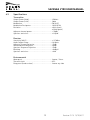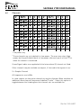
1
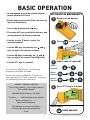
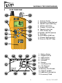
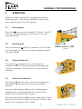
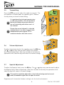
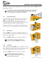
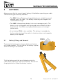
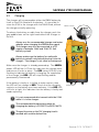
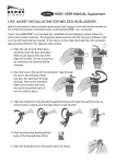
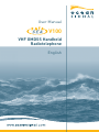
User Manual
V100
VHF GMDSS Handheld
Radiotelephone
English
© 2011 Ocean Signal Ltd
The technical data, information and illustrations contained in this manual were believed to
be correct at the time of print. Ocean Signal Ltd reserve the right to change specifications
and other information contained in this manual as part of our continual improvement
process.
No part of this manual may be reproduced, stored in a retrieval system or transmitted in
any form, electronic or otherwise, without the prior permission of Ocean Signal Ltd.
No liability can be accepted for any inaccuracies or omissions in this manual.
Ocean Signal® and SafeSea® are registered trademarks of Ocean Signal Ltd.
2
Part No. 912S-00957
BASIC OPERATION
• In emergency ensure the yellow Lithium
primary battery is fitted.
• Before operation break off the red security
tag from the battery.
• Turn on by pressing the
ACTIVATE IN EMERGENCY
1
Break seal on battery
2
Press
3
Adjust radio (if required)
key
• The radio will turn on with the distress and
calling channel 16 already selected
• Use the and keys to select the
required channel
to turn on
• Use the VOL key followed by the and
keys to adjust the speaker volume
• Use the SQ key followed by the and
keys to adjust the squelch (muting) level
• Use the PTT key to transmit
Select
Channel
To transmit a MAYDAY call the following
procedure should be followed.
Ensure the radio is turned on, channel 16 is
selected and the PTT key is pressed. Announce
the following clearly into the radio:
OR
Adjust
Volume
OR
Adjust
Squelch
OR
MAYDAY - MAYDAY - MAYDAY
“This is [Ship’s Name] - This is [Ship’s Name] This is [Ship’s Name]”
4
Press PTT key to transmit
“MAYDAY [Ship’s Name or Call Sign]”
“Position………… [LAT and LON or description]”
“Nature of Distress is ………..
[State the aid required]”
“The Number of Persons on board is…
[Followed by any useful information]”
DEACTIVATE
PRESS AND HOLD
“Over”
3
Version 01.10 12/12/2011
SAFESEA V100 USER MANUAL
CONTENTS
1
General . . . . . . . . . . . . . . . . . . . . . . . . . . . . . . . . . . . . . . . . . . . . . . . . . . . . . . . . . . . . . . . . .5
1.1 Exposure to RF Electromagnetic Energy . . . . . . . . . . . . . . . . . . . . . . . . . . . . . .5
1.2 Warnings . . . . . . . . . . . . . . . . . . . . . . . . . . . . . . . . . . . . . . . . . . . . . . . . . . . . . . . .5
1.3 Installation . . . . . . . . . . . . . . . . . . . . . . . . . . . . . . . . . . . . . . . . . . . . . . . . . . . . . .5
2
V100 Overview . . . . . . . . . . . . . . . . . . . . . . . . . . . . . . . . . . . . . . . . . . . . . . . . . . . . . . . . . . .6
3
Operation . . . . . . . . . . . . . . . . . . . . . . . . . . . . . . . . . . . . . . . . . . . . . . . . . . . . . . . . . . . . . . .7
3.1 Switching On . . . . . . . . . . . . . . . . . . . . . . . . . . . . . . . . . . . . . . . . . . . . . . . . . . . . .7
3.2 Switching Off . . . . . . . . . . . . . . . . . . . . . . . . . . . . . . . . . . . . . . . . . . . . . . . . . . . . .7
3.3 Channel Selection . . . . . . . . . . . . . . . . . . . . . . . . . . . . . . . . . . . . . . . . . . . . . . . .7
3.4 Channel 16 selection . . . . . . . . . . . . . . . . . . . . . . . . . . . . . . . . . . . . . . . . . . . . . .7
3.5 Transmitting . . . . . . . . . . . . . . . . . . . . . . . . . . . . . . . . . . . . . . . . . . . . . . . . . . . . .8
3.6 Volume Adjustment . . . . . . . . . . . . . . . . . . . . . . . . . . . . . . . . . . . . . . . . . . . . . . .8
3.7 Squelch Adjustment . . . . . . . . . . . . . . . . . . . . . . . . . . . . . . . . . . . . . . . . . . . . . . .8
3.8 Lights Adjustment . . . . . . . . . . . . . . . . . . . . . . . . . . . . . . . . . . . . . . . . . . . . . . . .9
3.9 Dual Watch . . . . . . . . . . . . . . . . . . . . . . . . . . . . . . . . . . . . . . . . . . . . . . . . . . . . . .9
3.10 Tri-Watch . . . . . . . . . . . . . . . . . . . . . . . . . . . . . . . . . . . . . . . . . . . . . . . . . . . . . . . .9
3.11 Scan . . . . . . . . . . . . . . . . . . . . . . . . . . . . . . . . . . . . . . . . . . . . . . . . . . . . . . . . . . .10
3.12 Memory Scan . . . . . . . . . . . . . . . . . . . . . . . . . . . . . . . . . . . . . . . . . . . . . . . . . . .10
3.13 Scan advance . . . . . . . . . . . . . . . . . . . . . . . . . . . . . . . . . . . . . . . . . . . . . . . . . . .10
3.14 Setting Scan Channels . . . . . . . . . . . . . . . . . . . . . . . . . . . . . . . . . . . . . . . . . . . .10
3.15 Hi/Lo . . . . . . . . . . . . . . . . . . . . . . . . . . . . . . . . . . . . . . . . . . . . . . . . . . . . . . . . . .11
3.16 Key Lock . . . . . . . . . . . . . . . . . . . . . . . . . . . . . . . . . . . . . . . . . . . . . . . . . . . . . . .11
4
Menu Mode . . . . . . . . . . . . . . . . . . . . . . . . . . . . . . . . . . . . . . . . . . . . . . . . . . . . . . . . . . . .12
4.1 Individual Menu Modes . . . . . . . . . . . . . . . . . . . . . . . . . . . . . . . . . . . . . . . . . . .13
5
Batteries . . . . . . . . . . . . . . . . . . . . . . . . . . . . . . . . . . . . . . . . . . . . . . . . . . . . . . . . . . . . . .15
5.1 Battery Fitting and Removal . . . . . . . . . . . . . . . . . . . . . . . . . . . . . . . . . . . . . .15
5.2 Warnings . . . . . . . . . . . . . . . . . . . . . . . . . . . . . . . . . . . . . . . . . . . . . . . . . . . . . . .16
5.3 Charging . . . . . . . . . . . . . . . . . . . . . . . . . . . . . . . . . . . . . . . . . . . . . . . . . . . . . . .17
6
Appendix . . . . . . . . . . . . . . . . . . . . . . . . . . . . . . . . . . . . . . . . . . . . . . . . . . . . . . . . . . . . . .18
6.1 Maintenance and Troubleshooting . . . . . . . . . . . . . . . . . . . . . . . . . . . . . . . . . .18
6.2 Transportation / Shipping . . . . . . . . . . . . . . . . . . . . . . . . . . . . . . . . . . . . . . . . .18
6.3 Specifications . . . . . . . . . . . . . . . . . . . . . . . . . . . . . . . . . . . . . . . . . . . . . . . . . . .19
6.4 Channels . . . . . . . . . . . . . . . . . . . . . . . . . . . . . . . . . . . . . . . . . . . . . . . . . . . . . .20
6.5 Accessories . . . . . . . . . . . . . . . . . . . . . . . . . . . . . . . . . . . . . . . . . . . . . . . . . . . . .21
6.6 Approvals . . . . . . . . . . . . . . . . . . . . . . . . . . . . . . . . . . . . . . . . . . . . . . . . . . . . . .21
6.7 Limited Warranty . . . . . . . . . . . . . . . . . . . . . . . . . . . . . . . . . . . . . . . . . . . . . . . .22
4
Part No. 912S-00957
SAFESEA V100 USER MANUAL
1
GENERAL
The V100 is supplied in the following packages:
GMDSS use only consisting of: V100 radio, antenna, lanyard (attached), Lithium emergency
battery, mounting bracket, user manual.
GMDSS and daily use consisting of: V100 radio, antenna, lanyard (attached), Lithium
emergency battery, Lithium Polymer rechargeable battery, charger, mains adaptor, supply
lead, user manual.
The V100 is also available with a waterproof accessory socket for the connection of
accessories such as headsets, helmets, speaker microphones, etc. Ocean Signal is not
able to supply these accessories directly, but will provide information to your chosen
supplier to allow suitable interfaces to be developed.
1.1
Exposure to RF Electromagnetic Energy
This product has been evaluated for compliance with the FCC RF exposure limits given in
CFR 47 part 1.307(b) at a distance of greater than 2.5cm.
1.2
Warnings
Do not operate without the antenna attached or with a damaged antenna.
Always operate with the antenna at least 2.5cm (1inch) away from your head
and do not transmit for more than 50% of the total time the radio is used.
Use of the radio in the body worn configuration with accessories is limited to
‘Occupational Use’ only. Do not transmit for more than 50% of the total time the
radio is used.
The use of this radio may be covered by licensing requirements in the country of
use. Please check with your local regulatory body before use.
Do not attempt to short circuit, burn or rupture the Lithium batteries. Use only
the recommended charger for the RB5V. See Section 5.2 for further details.
1.3
Installation
Unpack the contents of the box and check against the label fixed inside the box lid that the
contents are complete.
In the ‘GMDSS pack’, the SafeSea V100 is provided with a simple wall mounted cradle. In
the ‘Full pack’, the charger provided is used for storage of the radio. The cradle and
charger can be wall mounted using the two countersunk self-tapping screws provided.
Additionally the charger may be desktop mounted.
Ensure that the radio is mounted in accordance with IMO guidelines
where applicable.
5
Version 01.10 12/12/2011
SAFESEA V100 USER MANUAL
2
V100 OVERVIEW
1
2
12
3
1. Antenna Socket
2. Accessory socket (Option)
3. ON/OFF and LIGHTS key
4. Volume select key
5. Channel 16 select key
6. Squelch select key
7. Hi/Lo Power key
8. Speaker and Microphone
9. Scan key
10. Dual Watch (D/W) key
11. Channel Up/Down keys
12. Press to Talk (PTT) key
4
11
5
10
6
9
7
8
1
2
3
4
5
6
13
7
8
12
11
10
9
6
1. Battery Status
2. Keypad Locked
3. Lights Active
4. Confirmation
5. Transmit
6. Receive
7. Low Power (Tx)
8. Call Channel
9. Scan Inhibit
10. Memory Scan Enable
11. Channel number
12. Additional Information
13. Accessory Fitted
Part No. 912S-00957
SAFESEA V100 USER MANUAL
3
OPERATION
Ensure the radio is fitted with a charged battery before
commencing use. The primary battery will have the tab
intact indicating that it has full capacity.
3.1
Switching On
Press the
key to turn the SafeSea™ V100 on. The LCD
will start showing information, with channel 16 as the
selected channel.
3.2
PRESS = ON
Switching Off
Press and hold the
key for 3 seconds to turn the radio
off. The display will show a 3 second countdown, then the
LCD will go blank.
3.3
PRESS & HOLD = OFF
(3 secs)
Channel Selection
Pressing the
or
keys will scroll through the
available channels. Release the key when the required
channel is displayed. (See Section 6.4 for the available
channels).
3.4
Channel 16 selection
Pressing the 16 key will select channel 16 at high power.
Pressing the 16 key again will revert to the previous
channel.
Pressing and holding the 16 key until a double beep is
heard will select the designated CALL Channel. (See
Section 4 for setting the CALL channel.
Pressing and holding the 16 key until a triple beep is heard
will set the the current channel as the CALL Channel. (See
Section 4 for setting the CALL channel.
7
Version 01.10 12/12/2011
SAFESEA V100 USER MANUAL
3.5
Transmitting
Press the PTT key on the side of the radio to transmit. The
microphone is located under the speaker grille. Release
the key when you have finished talking.
It is good practice to keep transmissions
as short as possible. This will minimise
battery discharge and ensure that you
are not interfering with other users of
the channel.
Ensure the correct channel is selected
and that there is no other transmission
audible before pressing the PTT to
avoid interference with other users.
Microphone
3.6
Volume Adjustment
To adjust the volume level of the speaker, press the VOL key.
The
or keys may now be used to adjust the volume
Up or Down respectively. After two seconds of inactivity the
operation of the selection keys will revert to channel change.
3.7
Squelch Adjustment
To adjust the Squelch level, press the SQ key. The
or
keys may now be used to adjust
the Squelch Up or Down respectively. After two seconds of inactivity the operation of the
selection keys will revert to channel change.
The squelch should be adjusted to a level where background noise and
weak, unreadable signals do not open the mute.
Experience will show what the best setting is for the local environment.
8
Part No. 912S-00957
SAFESEA V100 USER MANUAL
To monitor a channel without adjusting squelch settings, press and hold the SQ key until a
double beep is heard.
The squelch will remain open while the key remains pressed and will
stay on for the time selected in the Menu after the key is released.
This mode may also be disabled in the Menu.
3.8
Lights Adjustment
To turn the lights on or off and adjust the level, press the
key. The
or
keys may now be used to adjust
the backlighting level from off through five levels to
maximum. After two seconds of inactivity the operation of
the selection keys will revert to channel change.
The lights will stay on for a period of 10sec (default) or as
set in the menu. Pressing any key will reactivate the lights.
3.9
Dual Watch
Press the D/W key to initiate the Dual Watch mode. The
radio will now start sampling the selected working channel
and channel 16 for signals.
Pressing the D/W or
key will terminate Dual Watch.
There will be no action if the radio is on
channel 16 when the D/W key is pressed.
3.10
Tri-Watch
Pressing and holding the D/W key for 1 second will initiate a
triple channel watch between the selected working channel,
the user programmed Call channel and channel 16.
Pressing the D/W or
key will terminate Tri-Watch.
A working channel and call channel
must have been entered before this key
press will have any action.
9
HOLD
(1 sec)
Version 01.10 12/12/2011
SAFESEA V100 USER MANUAL
3.11
Scan
Press and hold the SCN key until a double beep is heard.
The radio will now start scanning all the channels in the
radio for a signal.
To exit scan mode, press the SCN or
key.
Often a channel will appear to exhibit a permanent signal or
is frequently used for traffic that is of no interest. In this
case when the scan has stopped on the channel,
pressing and holding the SCN key until the double beep is
heard will inhibit the channel from being scanned.
3.12
HOLD
(double beep)
Memory Scan
To enter the Memory Scan mode, press the SCN key. The
radio will now start scanning only those channels that are
entered into the scan memory for a signal.
If there are no channels already entered,
pressing this key will have no effect.
To exit the Memory Scan mode, press the SCN or
3.13
key.
Scan advance
In any of the scanning modes, if the radio has stopped on a
busy channel pressing the
key will recommence
scanning. NOTE: If the received signal on a busy channel
ceases, then the radio will automatically recommence
scanning after the set Scan Dwell Time (see section 4).
3.14
Setting Scan Channels
In the normal radio mode, it is possible to set scanning
options for each channel.
To enter channels into the scan memory, select the required
channel and double press the SCN key. The
legend will
appear on the LCD to indicate this channel is in the scan
memory. If the channel was already marked as a Memory
Scan channel, this operation will remove it from the scan
memory and the
PRESS x 2
legend will disappear.
10
Part No. 912S-00957
SAFESEA V100 USER MANUAL
To inhibit a channel from the all scan memory, press and
hold the SCN key until a triple beep is heard. This will
inhibit the channel from scanning and the
legend will
appear on the LCD.
If the channel was already inhibited as a scan channel, this
operation will re-enable it and the
legend will disappear.
HOLD
(triple beep)
3.15
Hi/Lo
The HI/LO key will toggle the transmit power from high to
low. The
legend will be shown when low power (1 Watt)
is selected.
3.16
Key Lock
Press and hold the HI/LO key until a double beep is heard
to lock the keypad against accidental use. Press and hold
HI/LO again to unlock the keypad (the keylock will be
disabled when the radio is turned off).
HOLD
NOTE: The default setting for the key lock is off, to enable
key lock function see Section 4.
11
(double beep)
Version 01.10 12/12/2011
SAFESEA V100 USER MANUAL
4
MENU MODE
In the menu mode the following options are available:
HOLD
(double beep)
• Memory Scan Enable
• All Scan Inhibit
• Key Lock
• Key Beep Disable
• Scan Dwell Time
• Light Dwell Time
• Squelch Override Defeat
• Squelch Override Time
• Calling Channel Select
• Last Used Channel Enable
• Reset
• Serial number
• Software Issue.
To enter the Menu Mode, press and hold the MENU (VOL)
key until a double beep is heard.
Current Setting/Value
Once in the Menu mode, use the
or
keys to scroll
through the options listed above. The menu option will be
displayed in the additional area of the LCD screen.
When the desired option is selected, press the ENT (SQ) key
to enable adjusting the setting or value, shown in the channel number.
Use the
or
Menu Mode Selected
keys to adjust the value.
Press the ENT (SQ) key to enter the new value.
Press the 16 or MENU (VOL) key to exit Menu mode.
12
Part No. 912S-00957
SAFESEA V100 USER MANUAL
4.1
Individual Menu Modes
Mem Scan Enable (
)
In this Menu mode the channels that are marked with a for Memory Scan are shown.
Any number of channels may be so marked.
All Channel Scan Inhibit (
)
In this Menu mode the channels will be shown for marking as inhibited (or for re-enabling)
for All Channel Scan. Any number of channels can be so marked.
Key Lock (
)
This Menu mode allows the user to toggle the key lock functionality On or Off.
Key Beep Disable (
)
This Menu mode allows the user to toggle the first key beep On or Off. Note that the
second and third beeps remain active.
Scan Dwell Time (
)
This Menu mode allows selection of the dwell time in Scanning that the radio stays on the
channel after the received signal has gone away. The value shown is in seconds.
Light Dwell Time (
)
This menu mode allows selection of the time that the lights stay on after the last key
press. The value shown is in seconds.
Squelch Override (
)
The Menu mode option allows the user to enable or disable the squelch override mode.
Squelch Override Time (
)
This option allows the time the squelch override is open. It can be adjusted from 0 to
10seconds. Select the value of 0 seconds to only open the squelch while the key is
depressed.
Calling Channel Select (
)
This Menu mode allows selection of the Calling channel. This is the channel that the 16
key uses to toggle between channels.
13
Version 01.10 12/12/2011
SAFESEA V100 USER MANUAL
Last Used Channel enable (
)
This menu mode sets the radio to use the last used channel when it is turned on. The
Default is Off, in which case channel 16 is the default channel on turn on..
Reset (
)
This Menu Mode will clear all user settings and return them to the factory defaults.
Serial number (
)
This Menu Mode displays the radios serial number. The value cannot be changed by the
user.
SOFTWARE (
)
This Menu mode displays the current software version number. The value cannot be
changed by the user.
14
Part No. 912S-00957
SAFESEA V100 USER MANUAL
5
BATTERIES
Always ensure that the correct type of battery is fitted before operating your radio.
There are two types of battery available:
• The RB5V Lithium Polymer rechargeable battery is suitable for normal
everyday use of the radio. This battery should only be charged in the
recommended charger.
• The LB4V Lithium primary battery is for use in emergency only. This
battery is not rechargeable and is protected from accidental use by a
break-off tab. The LB4V is easily identifiable because of its bright
yellow colour.
• A test battery, TB6V, is also available. This battery is intended only
for the routine testing of the radios in situations where a rechargeable
battery is not required.
5.1
PRESS
Battery Fitting and Removal
To remove the battery, press the grey button on the base
of the radio inwards. This will release the battery clip and
allow the battery to be removed.
To fit the battery, push the top of the battery into the
radio, before pressing it home at the bottom. Ensure that
the grey button has locked the battery in place.
15
Version 01.10 12/12/2011
SAFESEA V100 USER MANUAL
5.2
Warnings
Do not attempt to charge the LB4V primary battery or the TB6V test
battery
Do not short circuit the battery terminals
Do not incinerate batteries
Do not attempt to puncture or dismantle batteries
Avoid exposing batteries to direct sunlight or temperatures below
-20°C (-4°F) or above 60°C (140°F)
In case of exposure to the cell contents, wash the affected area
thoroughly and seek medical attention.
Failure to follow these warnings may result in the battery exploding or catching fire
.
Extreme temperature caused by the failure to observe the above warnings may result in
the battery exploding or catching fire.
Dispose of batteries in a responsible manner. National or local regulations on battery
disposal may apply including restricting the disposal of batteries in domestic refuse.
16
Part No. 912S-00957
SAFESEA V100 USER MANUAL
5.3
Charging
The charger will accommodate either the RB5V battery by
itself or the V100 fitted with the battery. It is possible to
store the V100 in the charger with the LB4V fitted, without
the charger actually operating.
Release lever
To release the battery or radio from the charger, push the
grey paddle lever on the right hand side of the charger to
the left.
Always use the recommended charger and mains
adaptor when charging the RB5V battery pack.
The charger may also be connected to a DC
supply of between 10.8V and 15.6V (12 Volt
battery system)
Always make sure the battery (or radio with
battery inserted) is dry before placing it into the
charger. The charger is not rated as waterproof.
Make sure the charger is already powered up. The GREEN
power LED will be lit. Place the radio into the charger base
and ensure it locks in place. The RED status LED will start
flashing to indicate the battery is charging. On completion
of the charge, the RED LED will stop flashing and be
permanently illuminated.
If the battery is faulty or is failing to make contact, then
the LED will not change to RED. Check that the charging
contacts on the battery are clean and retry. If the RED LED
still fails to light, this indicates that the battery is faulty and
needs replacing.
Status LED
It is not recommended to transmit with the V100
while it is in the charger.
The recommended temperature range for
charging the battery is 0ºC(32ºF) to 40ºC(104ºF).
The positive wire on the 12V charging lead is
marked with a white dashed line.
17
Version 01.10 12/12/2011
SAFESEA V100 USER MANUAL
6
APPENDIX
6.1
Maintenance and Troubleshooting
The V100 Radiotelephone should not need servicing during its lifetime, with the exception
of changing the primary Lithium battery before the marked expiry date. The following
procedure is recommended to be carried out on a monthly basis.
Regular cleaning, inspection and testing of the radio is advised – clean any grime or salt
residue off the unit with a weak solution of detergent in warm water. Dry radio thoroughly
after cleaning. Never use solvents as this may affect the structural integrity of the plastics
used. Ensure that the battery and charger contacts are clean.
Testing should be carried out every month and should include a brief test transmission
to another VHF radiotelephone. The test may be carried out using a spare LB4V, a test
battery, TB6V, or using the rechargeable option, RB5V. Do not use the lithium battery
provided for emergency use as this will reduce the capacity available in a distress situation.
Where applicable testing should be carried out in accordance with IMO
recommendations or national guidelines.
Check the primary battery visually to ensure that the break-off tab is intact and that there
are no signs of damage on the battery case. Inspect the radio for signs of damage.
6.2
Transportation / Shipping
The battery packs, LB4V, RB5V and TB6V used with this radio are classed as non-hazardous
under the IATA Hazardous Transport Regulations.
LB4V
• The battery should be shipped as category 3090, and packing instruction
968:section II (excepted batteries).
• The radio with its battery should be shipped as category 3091, packing
instruction 969 section II (excepted batteries).
RB5V
• The battery should be shipped as category 3480, and packing instruction
965:section II (excepted batteries).
• The radio with its battery should be shipped as category 3481, packing
instruction 966 section II (excepted batteries).
TB6V
• There are no packing or shipping restrictions on alkaline batteries, provided
that they are adequately protected against short circuits in accordance with
Special Provision A164.
For road or sea transport both the LB4V and RB5V batteries may be shipped under Special
Provision A188 of the relevant regulations.
18
Part No. 912S-00957
SAFESEA V100 USER MANUAL
6.3
Specifications
Transmitter
Output Power (High) . . . . . . . . . . . . . . . . . . . . . . . . . 2.5Watts
Output Power (Low) . . . . . . . . . . . . . . . . . . . . . . . . . 1Watt
Modulation . . . . . . . . . . . . . . . . . . . . . . . . . . . . . . . . . FM (G3E)
Modulation Designator . . . . . . . . . . . . . . . . . . . . . . . 16K0G3EJN
Deviation . . . . . . . . . . . . . . . . . . . . . . . . . . . . . . . . . . ±3kHz (nom)
<±5kHz (peak)
Adjacent channel power . . . . . . . . . . . . . . . . . . . . . . <-70dBc
Spurious emissions . . . . . . . . . . . . . . . . . . . . . . . . . <0.25μW
Receiver
Sensitivity (MUS) . . . . . . . . . . . . . . . . . . . . . . . . . . . . ≤-117dBm
Audio Output Power . . . . . . . . . . . . . . . . . . . . . . . . . 0.4 Watts
Adjacent Channel Rejection . . . . . . . . . . . . . . . . . . . >70dB
Intermodulation Rejection . . . . . . . . . . . . . . . . . . . . ≥68dB
Spurious Response Rejection . . . . . . . . . . . . . . . . . >70dB
Blocking . . . . . . . . . . . . . . . . . . . . . . . . . . . . . . . . . . . >90dBμV
Spurious emissions . . . . . . . . . . . . . . . . . . . . . . . . . <2nW
Environmental
Waterproof . . . . . . . . . . . . . . . . . . . . . . . . . . . . . . . . . 1metre / 1hour
Thermal shock . . . . . . . . . . . . . . . . . . . . . . . . . . . . . 45°C
Drop proof (hard surface) . . . . . . . . . . . . . . . . . . . . . 1metre any side
19
Version 01.10 12/12/2011
SAFESEA V100 USER MANUAL
6.4
Channels
1
Low power only
2
These channels are set to default to Low power. The user may select High
power, but they will default back to Low power after each press of the PTT or
when the channel is reselected.
Ocean Signal radios are supplied with the International (I) channel set fitted.
Other channels may be available on request, if licensed in the region of use.
S = Simplex Channel
All frequencies are in MHz
In some regions an alternative channel set may be allowed. When available an
additional menu item will be present labelled "Locale". Select this option to
toggle between the listed regions that channel sets are available for.
20
Part No. 912S-00957
SAFESEA V100 USER MANUAL
6.5
Accessories
Lithium primary battery
LB4V
For use as an emergency battery, compliant
with the GMDSS carriage requirements.
Lithium Polymer rechargeable battery
RB5V
Rechargeable battery for everyday use.
Test battery
TB6V
Alkaline battery for monthly testing of the V100.
Lithium Polymer battery charging kit
721S-00622
Includes the RC1V rapid charger for the RB5V, mains
adaptor with universal plugs and a 12 Volt supply lead.
6.6
Approvals
The SafeSea™ V100 complies with the requirements of Annex A 1/5.17 of European
Directive 96/98/EC as amended, for use onboard ships registered in the European Union.
The SafeSea™ V100 complies with the GMDSS provisions of part 80 of the FCC rules.
Europe
Marine Equipment Directive MED A.1/5.17
IEC61097-12
IEC60945
USA
FCC Approved; FCC ID: XYEV100
IMO Resolutions
A.694(17), MSC.149(77)
.
21
Version 01.10 12/12/2011
SAFESEA V100 USER MANUAL
6.6
Limited Warranty
All servicing and repairs on the radio must be carried out by an approved service agent.
Please retain the original packaging for your radio. If the radio has to be returned for any
reason, the original packaging should be used.
Your SafeSea V100 radiotelephone is warranted against manufacturing defects and
workmanship for a period of two years from date of purchase. Ocean Signal Ltd will, a
its discretion, repair or replace a faulty product free of charge, including return carriage
costs to the owner.
For further assistance, please contact our Technical Service Department:
Email: [email protected]
Accidental damage and misuse or non-approved modifications are not covered by this
warranty. This warranty does not affect your statutory rights.
Dealer Stamp:
Date of Purchase:
22
Part No. 912S-00957
Ocean Signal Ltd.
Unit 4, Ocivan Way
Margate
CT9 4NN
United Kingdom
[email protected]
www.oceansignal.com