1
User s Manual
User’s Manual
PF
R-IN32M3 Series
User’s Manual
(CC-Link IE Field Intelligent device station)
・R-IN32M3-CL
All information of mention is things at the time of this document publication, and Renesas
Electronics may change the product or specifications that are listed in this document without
a notice. Please confirm the latest information such as shown by website of Renesas
Document number:R18UZ0015EJ0200
Issue date : Dec 25, 2014
Renesas Electronics
www.renesas.com
Notice
1.
2.
3.
4.
5.
Descriptions of circuits, software and other related information in this document are provided only to illustrate the
operation of semiconductor products and application examples. You are fully responsible for the incorporation of these
circuits, software, and information in the design of your equipment. Renesas Electronics assumes no responsibility for
any losses incurred by you or third parties arising from the use of these circuits, software, or information.
Renesas Electronics has used reasonable care in preparing the information included in this document, but Renesas
Electronics does not warrant that such information is error free. Renesas Electronics assumes no liability whatsoever
for any damages incurred by you resulting from errors in or omissions from the information included herein.
Renesas Electronics does not assume any liability for infringement of patents, copyrights, or other intellectual property
rights of third parties by or arising from the use of Renesas Electronics products or technical information described in
this document. No license, express, implied or otherwise, is granted hereby under any patents, copyrights or other
intellectual property rights of Renesas Electronics or others.
You should not alter, modify, copy, or otherwise misappropriate any Renesas Electronics product, whether in whole or
in part. Renesas Electronics assumes no responsibility for any losses incurred by you or third parties arising from such
alteration, modification, copy or otherwise misappropriation of Renesas Electronics product.
Renesas Electronics products are classified according to the following two quality grades: "Standard" and "High
Quality". The recommended applications for each Renesas Electronics product depends on the product's quality grade,
as indicated below.
"Standard":
Computers; office equipment; communications equipment; test and measurement equipment; audio
and visual equipment; home electronic appliances; machine tools; personal electronic equipment;
and industrial robots etc.
"High Quality": Transportation equipment (automobiles, trains, ships, etc.); traffic control systems; anti-disaster
systems; anti-crime systems; and safety equipment etc.
Renesas Electronics products are neither intended nor authorized for use in products or systems that may pose a
direct threat to human life or bodily injury (artificial life support devices or systems, surgical implantations etc.), or may
cause serious property damages (nuclear reactor control systems, military equipment etc.). You must check the quality
grade of each Renesas Electronics product before using it in a particular application. You may not use any Renesas
Electronics product for any application for which it is not intended. Renesas Electronics shall not be in any way liable
for any damages or losses incurred by you or third parties arising from the use of any Renesas Electronics product for
which the product is not intended by Renesas Electronics.
6. You should use the Renesas Electronics products described in this document within the range specified by Renesas
Electronics, especially with respect to the maximum rating, operating supply voltage range, movement power voltage
range, heat radiation characteristics, installation and other product characteristics. Renesas Electronics shall have no
liability for malfunctions or damages arising out of the use of Renesas Electronics products beyond such specified
ranges.
7. Although Renesas Electronics endeavors to improve the quality and reliability of its products, semiconductor products
have specific characteristics such as the occurrence of failure at a certain rate and malfunctions under certain use
conditions. Further, Renesas Electronics products are not subject to radiation resistance design. Please be sure to
implement safety measures to guard them against the possibility of physical injury, and injury or damage caused by fire
in the event of the failure of a Renesas Electronics product, such as safety design for hardware and software including
but not limited to redundancy, fire control and malfunction prevention, appropriate treatment for aging degradation or
any other appropriate measures. Because the evaluation of microcomputer software alone is very difficult, please
evaluate the safety of the final products or systems manufactured by you.
8. Please contact a Renesas Electronics sales office for details as to environmental matters such as the environmental
compatibility of each Renesas Electronics product. Please use Renesas Electronics products in compliance with all
applicable laws and regulations that regulate the inclusion or use of controlled substances, including without limitation,
the EU RoHS Directive. Renesas Electronics assumes no liability for damages or losses occurring as a result of your
noncompliance with applicable laws and regulations.
9. Renesas Electronics products and technology may not be used for or incorporated into any products or systems
whose manufacture, use, or sale is prohibited under any applicable domestic or foreign laws or regulations. You should
not use Renesas Electronics products or technology described in this document for any purpose relating to military
applications or use by the military, including but not limited to the development of weapons of mass destruction. When
exporting the Renesas Electronics products or technology described in this document, you should comply with the
applicable export control laws and regulations and follow the procedures required by such laws and regulations.
10. It is the responsibility of the buyer or distributor of Renesas Electronics products, who distributes, disposes of, or
otherwise places the product with a third party, to notify such third party in advance of the contents and conditions set
forth in this document, Renesas Electronics assumes no responsibility for any losses incurred by you or third parties as
a result of unauthorized use of Renesas Electronics products.
11. This document may not be reproduced or duplicated in any form, in whole or in part, without prior written consent of
Renesas Electronics.
12. Please contact a Renesas Electronics sales office if you have any questions regarding the information contained in
this document or Renesas Electronics products, or if you have any other inquiries.
(Note 1) "Renesas Electronics" as used in this document means Renesas Electronics Corporation and also includes its
majority-owned subsidiaries.
(Note 2) "Renesas Electronics product(s)" means any product developed or manufactured by or for Renesas Electronics.
Instructions for the use of product
In this section, the precautions are described for over whole of CMOS device.
Please refer to this manual about individual precaution.
When there is a mention unlike the text of this manual, a mention of the text takes first priority
1.Handling of Unused Pins
Handle unused pins in accord with the directions given under Handling of Unused Pins in the manual.
-The input pins of CMOS products are generally in the high-impedance state. In operation with an unused pin in the
open-circuit state, extra electromagnetic noise is induced in the vicinity of LSI, associated shoot-through current
flows internally, and malfunctions occur due to the false recognition of the pin state as an input signal become
possible. Unused pins should be handled as described under Handling of Unused Pins in the manual.
2.Processing at Power-on
The state of the product is undefined at the moment when power is supplied.
-The states of internal circuits in the LSI are indeterminate and the states of register settings and pins are undefined
at the moment when power is supplied.
In a finished product where the reset signal is applied to the external reset pin, the states of pins are not
guaranteed from the moment when power is supplied until the reset process is completed.
In a similar way, the states of pins in a product that is reset by an on-chip power-on reset function are not
guaranteed from the moment when power is supplied until the power reaches the level at which resetting has
been specified.
3.Prohibition of Access to Reserved Addresses
Access to reserved addresses is prohibited.
-The reserved addresses are provided for the possible future expansion of functions. Do not access these
addresses; the correct operation of LSI is not guaranteed if they are accessed.
4.Clock Signals
After applying a reset, only release the reset line after the operating clock signal has become stable. When switching
the clock signal during program execution, wait until the target clock signal has stabilized.
-When the clock signal is generated with an external resonator (or from an external oscillator) during a reset, ensure
that the reset line is only released after full stabilization of the clock signal. Moreover, when switching to a clock
signal produced with an external resonator (or by an external oscillator) while program execution is in progress,
wait until the target clock signal is stable.
・ARM, AMBA, ARM Cortex, Thumb and ARM Cortex-M3 are a trademark or a registered trademark of ARM Limited
in EU and other countries.
・Ethernet is a registered trademark of Fuji Zerox Limited.
・IEEE is a registered trademark of the Institute of Electrical and Electronics Engineers, Inc.
・EtherCAT is a registered trademark of Beckhoff Automation GmbH, Germany.
・CC-Link and CC-Link IE Field are a registered trademark of CC-Link Partner Association (CLPA).
・Additionally all product names and service names in this document are a trademark or a registered trademark
which belongs to the respective owners.
・Real-Time OS Accelerator and Hardware Real-Time OS is based on Hardware Real-Time OS of “ARTESSO” made
in KERNELON SILICON Inc.
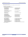
How to use this manual
1.
Purpose and target readers
This manual is intended for users who wish to understand the functions of
“ CC-Link IE Field Nework of intelligent
device station” for designing application of it.
It is assumed that the reader of this manual has general knowledge in the fields of electrical engineering, logic circuits,
and microcontrollers.
Particular attention should be paid to the precautionary notes when using the manual. These notes occur
within the body of the text, at the end of each section, and in the Usage Notes section.
The revision history summarizes the locations of revisions and additions. It does not list all revisions. Refer to
the text of the manual for details.
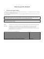
Related
Literature may be preliminary versions. Note, however, that the following descriptions do not indicate
Documents
"Preliminary". Some documents on cores were created when they were planned or still under
development. So, they may be directed to specific customers. Last four digits of document
number(described as ****) indicate version information of each document. Please download the latest
document from our web site and refer to it.
The document related to CC-Link IE Field Network
Document name
Document number
R-IN32M3 Series Datasheet
R18DS0008EJ****
R-IN32M3-CL User’s Manual
R18UZ0005EJ****
R-IN32M3 series User’s Manual Peripheral function
R18UZ0007EJ****
R-IN32M3 Series Proguraming Manual (OS edition)
R18UZ0011EJ****
R-IN32M3 Series Proguraming Manual (Driver edition)
R18UZ0009EJ****
R-IN32M3 Series User’s Manual CC-Link IE Intelligent device station
This manual
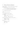
2.
Notation of Numbers and Symbols
Weight in data notation:
Left is high-order column, right is low-order column
Active low notation:
xxxZ
(capital letter Z after pin name or signal name)
or
xxx_N
or
xxnx
(capital letter _N after pin name or signal name)
(pin name or signal name contains small letter n)
Note:
explanation of (Note) in the text
Caution:
Item deserving extra attention
Remark:
Supplementary explanation to the text
Numeric notation:
Binary … xxxx , xxxxB or n’bxxxx (n bits)
Decimal … xxxx
Hexadecimal … xxxxH or n’hxxxx (n bits)
Prefixes representing powers of 2 (address space, memory capacity):
K (kilo)… 210 = 1024
M (mega)… 220 = 10242
G (giga)… 230 = 10243
Data Type:
Double word … 32 bits
Word … 16 bits
Byte … 8 bits
Contents
1.
2.
3.
4.
Basic Design Precautions.............................................................................................................................. 1
1.1
Component selection........................................................................................................................................... 1
1.2
Circuit design ...................................................................................................................................................... 2
1.3
Pattern design...................................................................................................................................................... 2
STATUS DISPLAY FUNCTIONS .................................................................................................................. 3
2.1
LED Based Status Displays ................................................................................................................................ 3
2.2
Controlling the LEDs .......................................................................................................................................... 4
2.2.1
LED control overview ............................................................................................................................... 4
2.2.2
Controlling User LED 1 and User LED 2 .................................................................................................. 6
2.2.3
Controlling the L.ERR LED ...................................................................................................................... 6
2.2.4
Enabling/Disabling LEDs .......................................................................................................................... 6
DATA COMMUNICATION METHOD ............................................................................................................ 7
3.1
Procedure for Cyclic Communication Process ................................................................................................... 7
3.2
Procedure for Transient Communication Process ............................................................................................... 8
3.3
Frame Format Overview for Transient Communication ................................................................................... 12
3.3.1
Transient1 frame format .......................................................................................................................... 13
3.3.2
TransientAck frame format ...................................................................................................................... 33
3.3.3
Transient2 frame format .......................................................................................................................... 35
DEVELOPING FIRMWARE......................................................................................................................... 48
4.1
Development Procedure .................................................................................................................................... 48
4.2
Sample Flowcharts of User Program ................................................................................................................ 52
4.2.1
General flowchart .................................................................................................................................... 54
4.2.2
Initialization processing ........................................................................................................................... 55
4.2.3
Start Communication processing ............................................................................................................. 56
4.2.4
Check PHY processing ............................................................................................................................ 57
4.2.5
Change PHY Setting processing .............................................................................................................. 58
4.2.6
Force Stop processing .............................................................................................................................. 59
4.2.7
Stop Cyclic Communication processing .................................................................................................. 59
4.2.8
Event processing ...................................................................................................................................... 60
4.2.9
Receive MyStatus from Master Station and Cyclic Data processing ....................................................... 61
4.2.10
Send MyStatus processing ....................................................................................................................... 62
4.2.11
Send Cyclic Data processing ................................................................................................................... 62
Contents-1
4.2.12
Update Communication Status processing .............................................................................................. 63
4.2.13
Update Cyclic Communication Status processing ................................................................................... 64
4.2.14
Get MIB Information processing ............................................................................................................. 65
4.2.15
Receive Transient1, Transient2, and TransientAck processing ............................................................... 68
4.2.16
Send Transient1, Transient2, and TransientAck processing .................................................................... 70
4.2.17
Received Transient1 Data processing ...................................................................................................... 71
4.2.18
Start Making Received Transient1 Data processing ................................................................................ 72
4.2.19
Make Received Transient1 Data processing ............................................................................................ 73
4.2.20
Received Node Information Distribution Frame processing.................................................................... 74
4.2.21
Check Node Information Distribution Frame processing ........................................................................ 75
4.2.22
Received Statistical Information Request Frame processing ................................................................... 76
4.2.23
Create Get Statistical Information Response Frame processing .............................................................. 77
4.2.24
Received Detailed Node Information Request Frame processing............................................................ 79
4.2.25
Create Get Detailed Node Information Response Frame processing ....................................................... 80
4.2.26
Received Transient2 Data processing ...................................................................................................... 82
4.2.27
Check Received Transient2 Data processing ........................................................................................... 83
4.2.28
Received TransientAck Data processing ................................................................................................. 83
4.2.29
Create TransientAck Frame processing ................................................................................................... 84
4.2.30
Create Transient2 Response Frame processing........................................................................................ 86
4.2.31
Create Transient2 Get Memory Request Frame processing..................................................................... 88
4.2.32
Received Transient2 Set Memory Request processing ............................................................................ 90
4.2.33
Received Transient2 Get Memory Response processing ......................................................................... 91
4.2.34
Hardware test (IEEE 802.3ab compliance test) ....................................................................................... 92
4.2.35
Hardware test (loop-back communication test) ....................................................................................... 93
4.3
Sample Code File List....................................................................................................................................... 96
4.3.1
Folder configuration ................................................................................................................................ 96
4.3.2
File list ..................................................................................................................................................... 96
4.4
Interface Function List for R-IN32M3-CL Driver ............................................................................................ 98
4.5
R-IN32M3-CL Driver Interface Function Details .......................................................................................... 100
4.5.1
Initial setup ............................................................................................................................................ 101
4.5.2
Watchdog timer ..................................................................................................................................... 109
4.5.3
Event ...................................................................................................................................................... 111
4.5.4
Cyclic communication ........................................................................................................................... 114
4.5.5
Own station status setup ........................................................................................................................ 117
4.5.6
Host station status acquisition................................................................................................................ 118
4.5.7
LED control ........................................................................................................................................... 123
4.5.8
Network time ......................................................................................................................................... 127
4.5.9
MDIO access ......................................................................................................................................... 129
4.5.10
Transient reception processing .............................................................................................................. 131
Contents-2
4.5.11
Transient transmission processing ......................................................................................................... 133
4.5.12
Interrupts ................................................................................................................................................ 137
4.5.13
Hardware tests ....................................................................................................................................... 138
4.6
Customizing the Target-Dependent Function Group for the R-IN32M3-CL Driver ...................................... 140
4.6.1
Changing the header file ........................................................................................................................ 140
4.6.2
Creating a target-dependent function group for the R-IN32M3-CL driver ............................................ 141
4.7
Customizing the Call-Back Function Group for the R-IN32M3-CL Driver ................................................... 145
Contents-3
Contents of Figures
Figure 2.1
External AND Logic for Turning L.ERR On ........................................................................................ 6
Figure 3.1
Transient1 Response Procedure (Request Source: Master Station) ...................................................... 9
Figure 3.2
Transient2 Response Procedure (Request Source: Other than Master Station)................................... 10
Figure 3.3
Transient2 Request Procedure............................................................................................................. 11
Figure 3.4
Transient Frame Common Header ...................................................................................................... 14
Figure 3.5
Transient1 Header ............................................................................................................................... 16
Figure 3.6
Transient1 Header: Relationship between Sequential No. and Identification No. of Transient Data . 17
Figure 3.7
Transient1 Data Area .......................................................................................................................... 18
Figure 3.8
Transient1 Data Area: Frames When Distribute Node Information Request Is Divided .................... 20
Figure 3.9
Transient1 Data Area: Distribute Node Information Request ............................................................. 21
Figure 3.10
Transient1 Data Area: Distribute Node Information Request - Frame 1 ............................................ 22
Figure 3.11
Transient1 Data Area: Distribute Node Information Request - Frame 2 ............................................ 23
Figure 3.12
Transient1 Data Area: Get Statistical Information Request ................................................................ 26
Figure 3.13
Transient1 Data Area: Get Statistical Information Response ............................................................. 27
Figure 3.14
Transient1 Data Area: Get Detailed Node Information Request ........................................................ 29
Figure 3.15
Transient1 Data Area: Get Detailed Node Information Response ...................................................... 30
Figure 3.16
TransientAck Data Area ..................................................................................................................... 34
Figure 3.17
Transient2 Header ............................................................................................................................... 36
Figure 3.18
Return Code (RSTS) ........................................................................................................................... 39
Figure 3.19
Data Area of Get Memory Access Information Response .................................................................. 40
Figure 3.20
Access Code ........................................................................................................................................ 40
Figure 3.21
RUN Request Data Area ..................................................................................................................... 42
Figure 3.22
RUN Response Data Area .................................................................................................................. 42
Figure 3.23
STOP Request Data Area.................................................................................................................... 43
Figure 3.24
STOP Response Data Area ................................................................................................................. 43
Figure 3.25
Get Memory Request .......................................................................................................................... 44
Figure 3.26
Attributes ............................................................................................................................................ 44
Figure 3.27
Get Memory Response ........................................................................................................................ 45
Figure 3.28
Set Memory Request ........................................................................................................................... 46
Figure 3.29
Set Memory Response ........................................................................................................................ 47
Figure 4.1
Configuration of Firmware ................................................................................................................. 49
Figure 4.2
Firmware Development Procedure...................................................................................................... 51
Figure 4.3
General Flowchart ............................................................................................................................... 54
Figure 4.4
Initialization Processing Flowchart ..................................................................................................... 55
Figure 4.5
Start Communication Processing Flowchart ....................................................................................... 56
Figure 4.6
Check PHY Processing Flowchart ...................................................................................................... 57
Figure 4.7
Change PHY Setting Flowchart .......................................................................................................... 58
Figure 4.8
Force Stop Processing Flowchart ........................................................................................................ 59
Figure 4.9
Stop Cyclic Communication Processing Flowchart ............................................................................ 59
Figure 4.10
Event Processing Flowchart ................................................................................................................ 60
Contents-4
Figure 4.11
Receive MyStatus from Master Station and Cyclic Data Processing Flowchart ................................ 61
Figure 4.12
Send MyStatus Processing Flowchart ................................................................................................. 62
Figure 4.13
Send Cyclic Data Processing Flowchart ............................................................................................. 62
Figure 4.14
Update Communication Status Processing Flowchart ........................................................................ 63
Figure 4.15
Update Cyclic Communication Status Processing Flowchart ............................................................. 64
Figure 4.16
Get MIB Information Processing Flowchart ....................................................................................... 65
Figure 4.17
Receive Transient1, Transient2, and TransientAck Processing Flowchart ......................................... 68
Figure 4.18
Create Transient2 Request Frame Processing Flowchart .................................................................... 69
Figure 4.19
Send Transient1, Transient2, and TransientAck Processing Flowchart .............................................. 70
Figure 4.20
Received Transient1 Data Processing Flowchart ................................................................................ 71
Figure 4.21
Start Making Received Transient1 Data Processing Flowchart .......................................................... 72
Figure 4.22
Make Received Transient1 Data Processing Flowchart ...................................................................... 73
Figure 4.23
Received Node Information Distribution Frame Processing Flowchart ............................................. 74
Figure 4.24
Check Node Information Distribution Frame Processing Flowchart .................................................. 75
Figure 4.25
Received Statistical Information Request Frame Processing Flowchart ............................................. 76
Figure 4.26
Create Get Statistical Information Response Frame Flowchart .......................................................... 77
Figure 4.27
Frame Format of Get Statistical Information Response ...................................................................... 78
Figure 4.28
Received Detailed Node Information Request Frame Processing Flowchart ..................................... 79
Figure 4.29
Create Get Detailed Node Information Response Frame Processing Flowchart................................. 80
Figure 4.30
Frame Format of Get Detailed Node Information Response .............................................................. 81
Figure 4.31
Received Transient2 Data Processing Flowchart ................................................................................ 82
Figure 4.32
Check Received Transient2 Data Processing Flowchart ..................................................................... 83
Figure 4.33
Received TransientAck Data Processing Flowchart ........................................................................... 83
Figure 4.34
Create TransientAck Frame Processing Flowchart ............................................................................. 84
Figure 4.35
I/G Bit ................................................................................................................................................. 84
Figure 4.36
Frame Format of TransientAck ........................................................................................................... 85
Figure 4.37
Create Transient2 Response Frame Processing Flowchart ................................................................. 86
Figure 4.38
Frame Format of Transient2 Response ............................................................................................... 87
Figure 4.39
Create Transient2 Get Memory Request Frame Processing Flowchart .............................................. 88
Figure 4.40
Frame Format of Transient2 Get Memory Request ............................................................................ 89
Figure 4.41
Received Transient2 Set Memory Request Processing Flowchart ...................................................... 90
Figure 4.42
Received Transient2 Get Memory Response Processing Flowchart ................................................... 91
Figure 4.43
Hardware Test (IEEE 802.3ab Compliance Test) Flowchart .............................................................. 92
Figure 4.44
Hardware Test (Loop-back Communication Test) Flowchart ............................................................ 94
Figure 4.45
Port Schematic View........................................................................................................................... 95
Contents-5
Contents of Tables
Table 1.1
Component Selection Check Sheet ........................................................................................................... 1
Table 1.2
Circuit Design Check Sheet ...................................................................................................................... 2
Table 1.3
Pattern Design Check Sheet ...................................................................................................................... 2
Table 2.1
LED Status Display List ........................................................................................................................... 3
Table 2.2
LED Control List ...................................................................................................................................... 5
Table 2.3
LEDs that Can Be Enabled/Disabled ........................................................................................................ 6
Table 3.1
Transient Communication List .................................................................................................................. 8
Table 3.2
Transient1 Frame Format Overview ....................................................................................................... 13
Table 3.3
MAC Header Items ................................................................................................................................. 15
Table 3.4
CC-Link IE Header Items ....................................................................................................................... 15
Table 3.5
Frame Type and Data Type List.............................................................................................................. 15
Table 3.6
Transient1 Header Items ......................................................................................................................... 16
Table 3.7
Extension Header Items .......................................................................................................................... 19
Table 3.8
Transient1 Command List ....................................................................................................................... 19
Table 3.9
Frame Format for Distribute Node Information Request ........................................................................ 20
Table 3.10
Distribute Node Information Header Items ......................................................................................... 24
Table 3.11
Node Information Data Area Items ..................................................................................................... 24
Table 3.12
Node Type List ................................................................................................................................... 25
Table 3.13
Get Statistical Information Data Items ................................................................................................ 28
Table 3.14
Data Area Items of Get Detailed Node Information Response (1/2) .................................................. 31
Table 3.15
Overview of TransientAck Frame Format .......................................................................................... 33
Table 3.16
TransientAck Data Items .................................................................................................................... 34
Table 3.17
Overview of Transient2 Frame Format ............................................................................................... 35
Table 3.18
Transient2 Header Items ..................................................................................................................... 37
Table 3.19
Transient2 Command Types ............................................................................................................... 38
Table 3.20
Access Code List (Example: Mitsubishi Product) .............................................................................. 41
Table 3.21
RUN Request Setting List ................................................................................................................... 42
Table 3.22
STOP Request Setting List ................................................................................................................. 43
Table 3.23
Get Memory Request .......................................................................................................................... 44
Table 3.24
Set Memory Request Setting List ....................................................................................................... 46
Table 4.1
List of Program Elements Included in Sample Code .............................................................................. 48
Table 4.2
List of Sample Flowcharts(1/2) ............................................................................................................... 52
Table 4.3
List of MIB Information of Ring Control Area ....................................................................................... 66
Table 4.4
List of MIB Information of MAC IP Area .............................................................................................. 66
Table 4.5
List of Other MIB Information ............................................................................................................... 67
Table 4.6
Test Item Precautions .............................................................................................................................. 93
Table 4.7
Troubleshooting Based on Hardware Test .............................................................................................. 94
Table 4.8
R-IN32M3-CL Driver Interface Function List ........................................................................................ 98
Table 4.9
R-IN32M3-CL Driver Interface Function List (Continued) ................................................................... 99
Table 4.10
List of Initial Values of Detailed Application Run Status ................................................................. 107
Contents-6
Table 4.11
Target-Dependent Function Group for R-IN32M3-CL Driver ......................................................... 141
Table 4.12
List of Call-Back Functions Used by R-IN32M3-CL Driver ............................................................ 145
Table 4.13
List of Fatal Error Codes of gR_IN32_CallbackFatalError Function ............................................... 146
Contents-7
R18UZ0015EJ0200
R-IN32M3 Series CC-Link IE Field
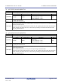
1.
Basic Design Precautions
1.1
Component selection
Dec 25, 2014
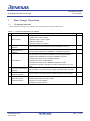
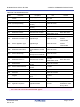
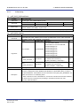
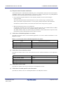
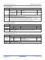
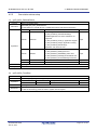
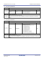
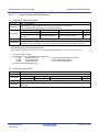
Select components taking into consideration the information provided in the table below.
Table 1.1 Component Selection Check Sheet
No.
Item
Description
Check
Did you select an MPU that satisfies the following specifications?
(1)Data width: 16 bits or higher
1
MPU selection
(2)Address width: 17 bits or higher
(3)Endian: Little endian
(4)Timing indicated in Chapter 4
2
3
RJ-45 connector
selection
Pulse transformer
selection
Is the connector an 8-pin ANSI/TIA/EIA-568-B shielded connector?
Did you select an IEEE 802.3 1000BASE-T compatible component?
Did you select a component that satisfies the following specifications?
(1)IEEE 802.3 1000BASE-T full duplex compatible component
(2)Component having an auto negotiation function
4
PHY selection
(3)Component having a GMII interface
(4)Component having an auto MDI/MDIX negotiation function
(5)Component capable of operating at an MDC clock frequency of 7.812
MHz
5
6
125-MHz crystal oscillator
selection
2.097152-MHz crystal
oscillator selection
Did you select a component having a frequency deviation within ±50 ppm?
Did you select a component having a frequency deviation with ±50 ppm?
Did you select a PHY clock crystal oscillator in accordance with the
7
PHY clock crystal
required specifications of the PHY used?
oscillator selection
Frequency of crystal oscillator
Total jitter of crystal oscillator
R18UZ0015EJ0200
Dec 25, 2014
Page
of 1491
R-IN32M3 Series CC-Link IE Field
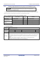
1.2
1. 0BBasic Design Precautions
Circuit design
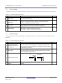
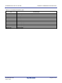
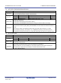
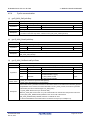
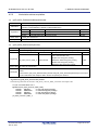
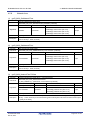
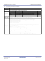
Design the peripheral circuits of R-IN32M3-CL taking into consideration the information provided in the table below.
Table 1.2 Circuit Design Check Sheet
No.
1
Item
GMII wiring
PHY- RJ45 connctor
2
connection
3
Data signal
Description
Check
Is a damping resistor installed for the GMII signal to supress
overshooting/undershooting?
The signal lines between PHY and RJ45 connector mus be connected in +
side and + side of each terminal, - side and – side of each terminal.
Otherwise 1000BASE-T compliance test fails.
Are pull-up resistors installed for the data signals D15 to D00? (10-kΩ
pull-up resistors are used in the circuit diagram examples.)
PHY address must be same as the port number of R-IN32M3-CL.
4
PHY address
PHY address 1 must be connected to MAC port 1.
PHY address 2 must be connected to MAC port 2<R>
1.3
Pattern design
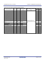
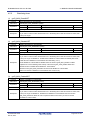
Design the pattern wiring of the R-IN32M3-CL periphery taking into consideration the information provided in the
table below.
Table 1.3 Pattern Design Check Sheet
No.
Item
2.097152-MHz crystal
1
oscillator connected to
R-IN32M3-CL
Description
Check
When connecting a 2.097152-MHz crystal oscillator to R-IN32M3-CL,
place the oscillator near R-IN32M3-CL. Is the pattern length to the the
CLK 2_097M pin shortest as possible? Is the pattern to the CLK 2_097M
pin shielded by SG patterns?
Has the wiring layer and signal line thickness for the signal (GMII), which
2
GMII wiring
connects R-IN32M3-CL and PHY, been determined to achieve shortest
pattern wiring and 50 Ω impedance?
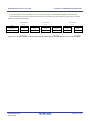
When a pattern is bent, is it always bent at 45 degrees as shown below?
OK
45°
Not acceptable
45°
3
4
Signal pattern bending
90°
Power supply / GND
Is the power supply / GND pattern wired using the thickest pattern
pattern
possible?
R18UZ0015EJ0200
Dec 25, 2014
Page 2 of 149
R-IN32M3 Series CC-Link IE Field
2. 1BSTATUS DISPLAY FUNCTIONS
2.
STATUS DISPLAY FUNCTIONS
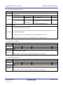
2.1
LED Based Status Displays
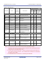
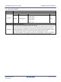
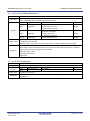
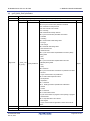
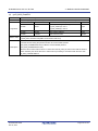
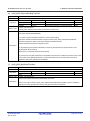
For an intelligent device station developed using R-IN32M3-CL, mount the LEDs for indicating the status of port 1,
port 2, and its host station as indicated in the table below.
For LED control, see Section 2.2.
Table 2.1 LED Status Display List
LED Name
LED Status
Function
LED On
LED Off
Status display of host station
PW
Power supply status
Power supply ON
Power supply OFF
RUN
Operating status
Normal
Not normal
RD
Data reception status
Receiving data
Not receiving data
SD
Data transmission status
Sending data
Not sending data
ERR
Error status
Disconnected (excluding cases
where cyclic communication has
Other than the left
never been implemented)
D LINK
Data link status
User LED 1
Note1
User LED 2
Note1
Cyclic communication in progress
User LED 1
Note2
―
User LED 2
Note2
―
stopped
Note1
Note1
Reception data error / line
L ERR.
Cyclic communication
error status
Error frame reception (Turns on
Normal frame reception
based on L ER. signal of each
(Turns off based on L ER.
port.)
signal of each port)
Link up
Link down
Error frame reception
Normal frame reception
Link up
Link down
Error frame reception
Normal frame reception
Status display of port 1 (option)
LINK
Port 1 link status
Note3
Port 1 reception data error
L ER
status
*3
Status display of port 2 (option)
LINK
Port 2 link status
Note3
Port 2 reception data error
L ER
status
Note3
Note 1. The LED names are provisional names.
Users can assign any name to these LEDs and use
the LEDs to implement a desired function.
For user LED control, see Section 2.2.2
“Controlling User LED 1 and User LED 2”
2. The mounting of this LED is optional.
3. The mounting of this LED is optional, bus recommended.
R18UZ0015EJ0200
Dec 25, 2014
Page 3 of 149
R-IN32M3 Series CC-Link IE Field
2.2
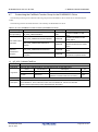
2.2.1
2. 1BSTATUS DISPLAY FUNCTIONS
Controlling the LEDs
LED control overview
Some LEDs are controlled by hardware (R-IN32M3-CL, PHY, and power check circuits), and some LEDs are
controlled by firmware.
The LEDs controlled by R-IN32M3-CL automatically turn on in accordance with the status of its host station. Wire the
LED (LINK LED) controlled by PHY so that the LED turns on when the PHY link is up.
The LEDs controlled by firmware are controlled by LED on/off control functions. See Section 4.5.7 "LED control."
R18UZ0015EJ0200
Dec 25, 2014
Page 4 of 149
R-IN32M3 Series CC-Link IE Field
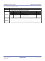
2. 1BSTATUS DISPLAY FUNCTIONS
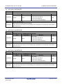
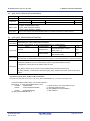
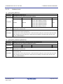
Table 2.2 LED Control List
Output at Reset/Error
Internal WDT /
R-IN32M3-C
LED Name
Function
Note3
L Output
Control Source
Signal Name
Power
System
External WDT /
ON Reset
Reset
Host Station
ErrorNote1
Status display of host station
Power supply
PW
status
RUN
Operating status
Data reception
RD
status
―
Power supply check circuit
―
―
―
RUNLEDL
Firmware, R-IN32M3-CL
Off
Off
Off
RDLEDL
R-IN32M3-CL
Off
―
―
SDLEDL
R-IN32M3-CL
Off
―
―
Data
SD
transmission
status
ERR
Error status
ERRLEDL
Firmware, R-IN32M3-CL
Off
Off
On
D LINK
Data link status
DLINKLEDL
Firmware, R-IN32M3-CL
Off
Off
Off
User
LED 1
User LED 1
Note2
Note2
USER1LEDL
Firmware, R-IN32M3-CL
Off
Off
Off
User LED 2
Note2
Note2
USER2LEDL
Firmware, R-IN32M3-CL
Off
Off
Off
―
―
―
―
―
―
Off
Off
Off
―
―
―
Off
Off
Off
User
LED 2
Turns on according to
Reception data
L ERR.
error / line error
―
status
LERR1LEDL and LERR2LEDL
signal statuses (external AND
*3
logic required)
Status display of port 1 (option)
PHY (Wire the LED so that it
LINK
Port 1 link status
―
turns on when the PHY link is
up.)
L ER
Port 1 reception
data error status
LERR1LEDL
Firmware, R-IN32M3-CL
Status display of port 2 (option)
PHY (Wire the LED so that it
LINK
Port 2 link status
―
turns on when the PHY link is
up.)
L ER
Port 2 reception
data error status
LERR2LEDL
Firmware, R-IN32M3-CL
Note 1. An error that occurs when firmware calls the function gerR_IN32_ForceStop.
For details of the function gerR_IN32_ForceStop, see Section 4.2.6 "Force Stop processing.”
and Section 4.5.5 "Own station status setup”
2. The LED names are provisional names.
use the LEDs to implement a function.
Vendors can assign any name to these LEDs and
For user LED control, see Section 2.2.2 “Controlling
User LED 1 and User LED 2”
3. For L.ERR LED control, see Section 2.2.3 “Controlling the L.ERR LED.”
R18UZ0015EJ0200
Dec 25, 2014
Page 5 of 149
R-IN32M3 Series CC-Link IE Field
2.2.2
2. 1BSTATUS DISPLAY FUNCTIONS
Controlling User LED 1 and User LED 2
R-IN32M3-CL provides two user LEDs, User LED 1 and User LED 2, where the user can assign desired functions.
You can control the on/off status of User LED 1 and User LED 2 using the functions gerR_IN32_SetUSER1LED and
ger R_IN32_SetUSER2LED.
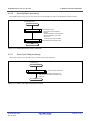
2.2.3
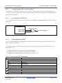
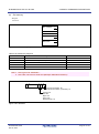
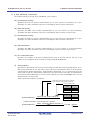
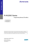
Controlling the L.ERR LED
For the L.ERR LED signal, set up the external AND logic for LERR1LEDL and LERR2LEDL in accordance with the
figure below.
R-IN32M3-CL
External AND logic
LERR1LEDL
LERR2LEDL
L.ERR LED signal
Figure 2.1 External AND Logic for Turning L.ERR On <R>
2.2.4
Enabling/Disabling LEDs
You can enable and disable the LEDs listed in the table below. Switch the LED enable/disable setting as necessary as
shown in the following example:
Example:Disable the L ER.LEDs of port 1 and port 2 in a link down state since the LED light sometimes stays on
when the link is down.
To disable an LED display, use the function gerR_IN32_DisableLED.
To enable an LED display, use the function gerR_IN32_EnableLED.
For LED display enable/disable functions, see Section 4.5.7 “LED control.”
Table 2.3 LEDs that Can Be Enabled/Disabled
LED Name
Function
Status display of host station
RUN
Operating status
ERR
Error status
D LINK
Data link status
User LED 1
User LED 1
User LED 2
User LED 2
Status display of port 1
L ER
Port 1 reception data error status
Status display of port 2
L ER
R18UZ0015EJ0200
Dec 25, 2014
Port 2 reception data error status
Page 6 of 149
R-IN32M3 Series CC-Link IE Field
3.
3. 2BDATA COMMUNICATION METHOD
DATA COMMUNICATION METHOD
CC-Link IE Field Network has two types of communication methods: cyclic communication and transient
communication.
3.1
Procedure for Cyclic Communication Process
Simply starting a R-IN32M3-CL driver interface function according to Section 4.2.1 "General flowchart" executes the
cyclic communication process. The R-IN32M3-CL driver interface functions are used to read and write RX, RY, RWr,
and RWw.
R18UZ0015EJ0200
Dec 25, 2014
Page 7 of 149
R-IN32M3 Series CC-Link IE Field
3.2
3. 2BDATA COMMUNICATION METHOD
Procedure for Transient Communication Process
In transient communication, data is transmitted and received between its host station and another station on a
one-to-one basis.
Transient communication involves Transient1 communication, which is required by the system, and Transient2
communication, which can be freely implemented by the vendor. Transient1 and Transient2 each involve requests and
responses, and any station that receives a request or response sends TransientAck as a response in acknowledgement.
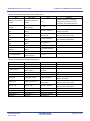
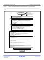
Table 3.1 Transient Communication List
Frame Type
Transient1 request
Transient1 response
TransientAck
Transient2 request
Transient2 response
Transmission/Reception
Intelligent Device
Master Station
Local Station
Transmission
O
×
×
Reception
×
O
O
Transmission
×
O
O
Reception
O
×
×
Transmission
O
O
O
Reception
O
O
O
Transmission
Δ
Δ
Δ
Reception
Δ
Δ
Δ
Transmission
Δ
Δ
Δ
Reception
Δ
Δ
Δ
Station
Remark ○ : Required, △ : Optional, × : Not required
To transmit and receive transient communication, firmware starts a R-IN32M3-CL driver interface function.
In transient communication, the request source sends a request frame, and the request destination sends a TransientAck
frame and response frame.
R18UZ0015EJ0200
Dec 25, 2014
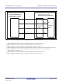
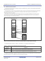
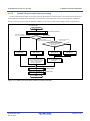
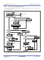
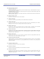
The following shows an image of transient communication.
Page 8 of 149
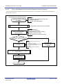
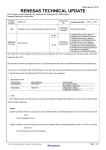
R-IN32M3 Series CC-Link IE Field
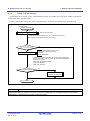
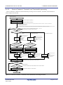
Request source (master station)
CC-Link IE Field Network
compatible station like a
programmable controller
3. 2BDATA COMMUNICATION METHOD
Request destination
Intelligent device station
developed using R-IN32M3-CL
[1]
[3]
R-IN32M3CL
[2]
Firmware
[6]
[4] [5]
[7]
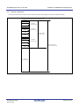
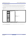
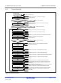
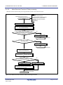
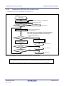
Figure 3.1 Transient1 Response Procedure (Request Source: Master Station) <R>
[1] The intelligent device station receives a Transient1 request frame. (See Section 4.2.15.)
[2] The intelligent device station creates a TransientAck frame. (See Section 4.2.29.)
[3] The intelligent device station sends the TransientAck frame. (See Section 4.2.16.)
[4] The intelligent device station analyzes the command of the Transient1 request frame. (See Sections 0 and 4.2.20.)
[5] The intelligent device station creates a Transient1 response frame in accordance with the command.
(See Sections 4.2.23 and 4.2.24.)
[6] The intelligent device station sends the Transient1 response frame. (See Section 4.2.16.)
[7] The intelligent device station receives a TransientAck frame. (See Section 4.2.15.)
R18UZ0015EJ0200
Dec 25, 2014
Page 9 of 149
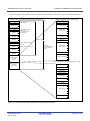
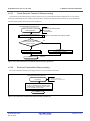
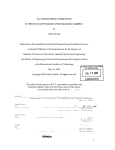
R-IN32M3 Series CC-Link IE Field
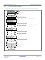
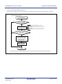
Request source
CC-Link IE Field Network
compatible station like a
programmable controller
3. 2BDATA COMMUNICATION METHOD
Request destination
Intelligent device station
developed using R-IN32M3-CL
[1]
[3]
R-IN32M3CL
[2]
Firmware
[6]
[4] [5]
[7]
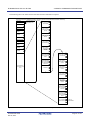
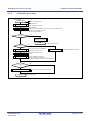
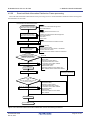
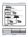
Figure 3.2 Transient2 Response Procedure <R>
[1] The intelligent device station receives a Transient2 request frame. (See Section 4.2.15.)
[2] The intelligent device station creates a TransientAck frame. (See Section 4.2.29.)
[3] The intelligent device station sends the TransientAck frame. (See Section 4.2.16.)
[4] The intelligent device station analyzes the command of the Transient2 request frame. (See Section 4.2.32.)
[5] The intelligent device station creates a Transient2 response frame in accordance with the command.
(See Section 4.2.30.)
[6] The intelligent device station sends the Transient2 response frame. (See Section 4.2.16.)
[7] The intelligent device station receives a TransientAck frame. (See Section 4.2.15.)
R18UZ0015EJ0200
Dec 25, 2014
Page 10 of 149
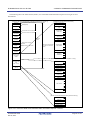
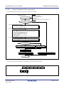
R-IN32M3 Series CC-Link IE Field
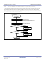
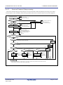
Request source
Request source
Intelligent device station
developed using R-IN32M3-CL
[1]
3. 2BDATA COMMUNICATION METHOD
CC-Link IE Field Network
compatible station like a
programmable controller
[2]
[3]
Firmware
[5]
[4]
R-IN32M3CL
[6]
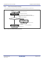
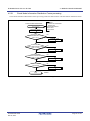
Figure 3.3 Transient2 Request Procedure
[1] The intelligent device station creates a Transient2 request frame. (See Section 4.2.30.)
[2] The intelligent device station sends the Transient2 request frame. (See Section 4.2.16.)
[3] The intelligent device station receives a TransientAck frame. (See Section 4.2.15.)
[4] The intelligent device station receives a Transient2 response frame. (See Sections 4.2.15 and 4.2.33.)
[5] The intelligent device station creates a TransientAck frame. (See Section 4.2.29.)
[6] The intelligent device station sends the TransientAck frame. (See Section 4.2.16.)
R18UZ0015EJ0200
Dec 25, 2014
Page 11 of 149
R-IN32M3 Series CC-Link IE Field
3.3
3. 2BDATA COMMUNICATION METHOD
Frame Format Overview for Transient Communication
The frame format of transient communication complies with the Ethernet frames of IEEE802.3. An Ethernet frame has
a frame size of 64 to 1518 bytes, from the MAC header to FCS.
This section describes the frames below which require format awareness in user programs.
• Transient1 frame
• TransientAck frame
• Transient2 frame
R18UZ0015EJ0200
Dec 25, 2014
Page 12 of 149
R-IN32M3 Series CC-Link IE Field
3.3.1
3. 2BDATA COMMUNICATION METHOD
Transient1 frame format
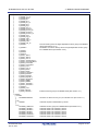
The table below provides an overview of the Transient1 frame format.
Table 3.2 Transient1 Frame Format Overview
Size
(Bytes)
Item
1
Transient frame common
header
28
Size
(Bytes)
Sub-Item
MAC header
14
CC-Link IE header
14
Remarks
2
Transient1 header
16
16
3
Transient1 data area
20 to 1466
4
DCS
4
4
Data Check Sequence
5
FCS
4
4
Frame Check Sequence
Extension header
20
Data
0 to 1446
Note
Note
Note Automatically calculated and added by R-IN32M3-CL
R18UZ0015EJ0200
Dec 25, 2014
Page 13 of 149
R-IN32M3 Series CC-Link IE Field
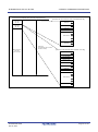
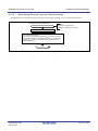
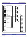
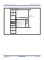
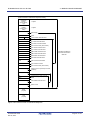
(1)
3. 2BDATA COMMUNICATION METHOD
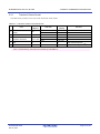
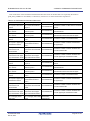
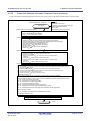
Transient frame common header
The transient frame common header is a header used in common by the Transient1 frame, TransientAck frame, and
Transient2 frame. The header comprises a MAC header, which is an Ethernet frame header, and a CC-Link IE header.
[Header format common to transient frames (MAC header / CC-Link IE header)]
H
Big endian
6 bytes (octets)
Destination address
L
MAC header
14 bytes
H
Big endian
6 bytes (octets)
Source address
L
Type H:0x89
L:0x0F
H
L
Big endian
2 bytes (octets)
H
L
Big endian
2 bytes (octets)
H
L
Big endian
2 bytes (octets)
Frame type
Data type
Node ID
Connection information
Reserved (0x00)
Own node number
Protocol version/type
Upper 4 bits: Version, Lower 4 bits: Type
CC-Link IE header
14 bytes
Reserved (0x00)
H
HEC
L
Big endian
4 bytes (octets)
L
Figure 3.4 Transient Frame Common Header
R18UZ0015EJ0200
Dec 25, 2014
Page 14 of 149
R-IN32M3 Series CC-Link IE Field
3. 2BDATA COMMUNICATION METHOD
Table 3.3 MAC Header Items
Item
Description
Destination address
Destination MAC
(octets 1 and 2)
address
Destination address
Destination MAC
(octets 3 and 4)
address
Destination address
Destination MAC
(octets 5 and 6)
address
Source address
(octets 1 and 2)
Source address
(octets 3 and 4)
Source address
(octets 5 and 6)
Type
Value
Remarks
0x0123 when the MAC address is
0x0000 to 0xFFFF
"01:23:45:67:89:AB."
0x4567 when the MAC address is
0x0000 to 0xFFFF
"01:23:45:67:89:AB."
0x89AB when the MAC address is
0x0000 to 0xFFFF
"01:23:45:67:89:AB."
0xF02E when the MAC address is
Source MAC address
0x0000 to 0xFFFF
Source MAC address
0x0000 to 0xFFFF
Source MAC address
0x0000 to 0xFFFF
Upper layer packet type
Fixed value: 0x890F
"F0:2E:15:6C:77:9B."
0x156C when the MAC address is
"F0:2E:15:6C:77:9B."
0x779B when the MAC address is
"F0:2E:15:6C:77:9B."
Note All items in this table are set using big endian.
Table 3.4 CC-Link IE Header Items
Item
Description
Value
Frame type
Type of frame
Data type
Type of data
Node ID
Node identifier 0 to 255
Remarks
See Table 3.5
This value is used in the
Acquired by function
gusR_IN32_GetNodeID.
CC-Link IE Field Network
*1
Connection
Transient identification
Acquired by function
information
information
gerR_IN32_GetSendTransientBuffer.
Reserved
Reserved
Fixed value: 0x00
Own node number
Own node number
1 to 120
Protocol version
Protocol version
Fixed value: 0x00
Protocol type
Protocol type
CC-Link IE Field Network: 0x1
HEC
Header Error Control
system.
*3
This information is for
*2
identifying the transient frame
sent during a single token hold.
Note3
Automatically calculated by
R-IN32M3-CL.
Note 1. See Section(2) of Section 4.5.11 “Transient transmission processing”.
2. See Section(5) of Section 4.5.11 “Transient transmission processing”.
3. Set using big endian.
Table 3.5 Frame Type and Data Type List
Frame Type
Value
Data Type
Transient1 frame
0x22
Transient communication specific to CC-Link IE
TransientAck frame
0x23
Field Network
Transient2 frame
0x25
CC-Link compatible transient communication
R18UZ0015EJ0200
Dec 25, 2014
Value
0x07
0x04
Page 15 of 149
R-IN32M3 Series CC-Link IE Field
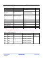
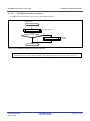
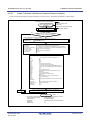
(2)
3. 2BDATA COMMUNICATION METHOD
Transient1 header
Transient1 header is a header added to a Transient1 frame.
[Transient1 header frame format]
H
Reserved
(0x00000000)
L
Sequential number
Identification
number
Any (0x00 to 0xFF)
Transient data H
overall size
L
Big endian
2 bytes (octets)
Transient1 header
H
Bit endian
4 bytes (octets)
Offset address
(from 0)
L
Big endian
2 bytes (octets)
Transient data H
size inside frame L
Data sub-type
H
L
Big endian 2 bytes (octets)
0x0002 (System specific)
Figure 3.5 Transient1 Header
Table 3.6 Transient1 Header Items
Item
Reserved
Sequential number
Description
Reserved
Sequential number of
Transient1 frame
Identification
Identification number of
number
transient data
Transient data
Number of bytes from
overall size
command to data
Value
Remarks
Fixed value: 0x00000000
Bit 7:Final frame (1b),
non-final frame (0b)
Bits 6 to 0:0x00 to 0x7F
0x00 to 0xFF
20 and up
Set the same identification number for
divided frames.
Note
The overall size of the transient data
prior to division
*1
Offset address from
Offset address
start (command) of
Note
0 and up
Fixed to 0 when not divided
12 to 1466
Size of transient data after division
System specific: 0x0002
Note
transient data in general
Transient data size
Size of Transient1 data
inside frame
area
Data sub-type
–
Note
Note Set in big endian format.
R18UZ0015EJ0200
Dec 25, 2014
Page 16 of 149
R-IN32M3 Series CC-Link IE Field
3. 2BDATA COMMUNICATION METHOD
The following shows the relationship between the sequential number and identification number of transient data.
The examples shows the first transient data not divided, the second transient data divided into three sections, and the
third transient data divided in half.
Transient Data
No. 1
Transient Data
No. 2
Transient Data
No. 3
Item
Sequential No.
0x80
0x00
Identification No.
0x01
0x02
Frame 1
(Final frame)
Frame 1
→
0x01
0x02
Frame 2
→
0x82
0x00
0x02
0x03
Frame 3
(Final frame)
Frame 1
→
0x81
0x03
Frame 2
(Final frame)
Figure 3.6 Transient1 Header: Relationship between Sequential No. and Identification No. of Transient Data
R18UZ0015EJ0200
Dec 25, 2014
Page 17 of 149
R-IN32M3 Series CC-Link IE Field
(3)
3. 2BDATA COMMUNICATION METHOD
Transient1 data area
The Transient1 data area is a data area for Transient1 frames, and comprises an extension header and data.
[Transient1 data area (extension header) frame format]
Command
Sub-command
Return value
H
L
Big endian
2 bytes (octets)
Reserved(0x00)
Destination network number
Destination nodeH
number
L
Reserved
(0x0000)
H
L
Reserved
(0x0000)
H
L
Big endian
2 bytes (octets)
Extension header
20 bytes (octets)
Reserved(0x00)
Source network number
Source node
number
H
L
Reserved
(0x0000)
H
L
Reserved
(0x0000)
H
L
Big endian
2 bytes (octets)
Transient1 data area
20 to 1466 bytes (octets)
Data
(0 to 1446 bytes)
Figure 3.7 Transient1 Data Area
R18UZ0015EJ0200
Dec 25, 2014
Page 18 of 149
R-IN32M3 Series CC-Link IE Field
3. 2BDATA COMMUNICATION METHOD
Table 3.7 Extension Header Items
Item
Description
Command
Command
Sub-command
Sub-command
Return value in response to
Return value
request
Value
Remarks
See Table 3.8
Request: 0x0000 (Fixed)
Response:0x0000 (Normal)
Note
0x0001 to 0xFFFF (Abnormal)
Reserved
Reserved
Destination network number
Destination network number
Destination node number
Destination node number
Fixed value: 0
Broadcast: 0
Destination network: 1 to 239
1 to 120
Master station: 0x007D
Note
Broadcast: 0xFFFF
Reserved
Reserved
Fixed value:0
Reserved
Reserved
Fixed value:0
Reserved
Reserved
Fixed value:0
Source network number
Source node number
Network number of transmission
source
Node number of transmission
source
1 to 239
1 to 120
Reserved
Reserved
Fixed value:0
Reserved
Reserved
Fixed value:0
Note
Note Set in big endian format.
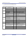
Table 3.8 Transient1 Command List
Command
Sub-Command
0x01
0x00
0x03
0x00
0x03
0x80
0x04
0x00
0x04
0x80
R18UZ0015EJ0200
Dec 25, 2014
Command Type
Distribute Node Information
request
Get Statistical Information
request
Get Statistical Information
response
Get Detailed Node
Information request
Get Detailed Node
Information response
Transmission Direction
Master station → Slave station
Remarks
Response not
required
Master station → Slave station
Master station ← Slave station
Master station → Slave station
Master station ← Slave station
Page 19 of 149
R-IN32M3 Series CC-Link IE Field
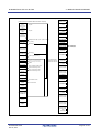
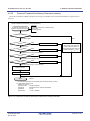
(a)
3. 2BDATA COMMUNICATION METHOD
Distribute node information
The Distribute Node Information command is used by the intelligent device station to find a destination MAC address
from a destination node number.
The intelligent device station sends a TransientAck frame in response to a Distribute Node Information request frame
received from the master station. Transmission of a Transient1 response frame (response to a Distribute Node
Information request) is not required.
If the number of sets of distributed node information is 60 or more, the frame is divided into two frames since the
frame size exceeds 1518 bytes, which is the maximum number of an Ethernet frame. In such a case, the Transient1
reception data needs to be assembled by firmware.
Transient1 data area Distribute Node
Information request: Frame 1
Transient1 data area Distribute Node
Information request data
Extension header
Extension header
Distribute Node
Information
header
Distribute Node
Information
header
No. 1
No. 1
No. 2
No. 2
No. 58
No. 59
No. 60
No. 61
Node information
data area
No. 58
No. 59
No. 60 (first half)
Transient1 data area Distribute Node
Information request: Frame 2
No. 60 (second half)
No. 119
No. 61
No. 120
No. 119
No. 120
Figure 3.8 Transient1 Data Area: Frames When Distribute Node Information Request Is Divided
For the frame format, see Table 3.9, Table 3.10, and Table 3.11 in accordance with the table below.
Table 3.9 Frame Format for Distribute Node Information Request
Number of
Distributions
Less than 60
60 or more
Reference
“Figure 3.9 Transient1 Data Area: Distribute Node Information Request”
“Figure 3.10 Transient1 Data Area: Distribute Node Information Request - Frame 1”
“Figure 3.11 Transient1 Data Area: Distribute Node Information Request - Frame 2”
For details on assembling the Transient1 reception data, see Section 4.2.18 "Start Making Received Transient1 Data
processing" and Section 4.2.19 "Make Received Transient1 Data processing."
R18UZ0015EJ0200
Dec 25, 2014
Page 20 of 149
R-IN32M3 Series CC-Link IE Field
3. 2BDATA COMMUNICATION METHOD
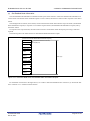
The following shows the frame format for a Distribute Node Information request involving less than 60 distributions.
[Distribute Node Information header format]
[Transient1 data area: Distribute Node Information request format]
Command
Sub-command
Return value
0x01(Distribute Node Information)
Distribution sequential number
0x00(Request)
Master station network number
Master station
model type
H
L
Reserved(0x00)
Destination network
number
Destination nodeH
number
L
Reserved
(0x0000)
H
L
Reserved
(0x0000)
H
L
H
Own network number
or broadcast
Own node number
or broadcast
Master station
model code
L
Master station
vendor code
Source node H
number
L
Reserved
(0x0000)
Reserved
(0x0000)
H
L
H
L
Master station node type
Extension header
Reserved
Reserved(0x00)
Source network number
H
L
H
Master station network
number
Master station node number
Data length
(Transient data size in
frame of Transient1
header)
Master station
MAC address
L
Reserved
H
L
H
Number of distributions
Distribute Node
Information
header
L
[Format of node information data area (Nos. 1 to 59)]
Node information
data area
(Nos. 1 to 59)
Node number
H
L
Reserved
Function status
Reserved
Network number
Model type
H
L
Vendor code
H
L
Node type
Reserved
H
MAC address
L
Reserved
H
L
Figure 3.9 Transient1 Data Area: Distribute Node Information Request
R18UZ0015EJ0200
Dec 25, 2014
Page 21 of 149
R-IN32M3 Series CC-Link IE Field
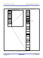
3. 2BDATA COMMUNICATION METHOD
The following shows the frame format (frame 1) for a Distribute Node Information request involving 60 or more
distributions.
[Distribute Node Information header format]
[Transient1 data area: Distribute Node Information request format - (frame 1)]
Command
Sub-command
Return value
0x01(Distribute Node Information)
Distribution sequential number
0x00(Request)
Master station network number
Master station model H
type
L
H
L
Reserved(0x00)
Destination network
number
H
Own network number or broadcast
Destination H
node number L
Reserved
(0x0000)
H
L
Reserved
(0x0000)
H
L
Master station
model code
Own node number or broadcast
L
Master station
vendor code
Master station node type
Extension
header
Reserved
Reserved(0x00)
Source network number
Source node H
number
L
Reserved
(0x0000)
H
L
Reserved
(0x0000)
H
L
Distribute Node
Information
header
H
Master station network
number
Master station node number
H
L
Data length (Transient data
size in frame of Transient1
header)
Master station
MAC address
L
Reserved
H
Number of
distributions
L
[Format of node information data area (Nos. 1 to 59)]
Distribute Node
Information data
area
(Nos. 1 to 59)
Node number
H
L
Reserved
Node information
data area
(No. 60)
Function status
Reserved
Network number
Model type
H
L
Vendor code
H
L
Node type
Reserved
H
MAC address
L
Reserved
H
L
[Format of node information data area (first half of No. 60)]
Node number
H
L
Reserved
Function status
Reserved
Network number
Figure 3.10 Transient1 Data Area: Distribute Node Information Request - Frame 1
R18UZ0015EJ0200
Dec 25, 2014
Page 22 of 149
R-IN32M3 Series CC-Link IE Field
3. 2BDATA COMMUNICATION METHOD
[Frame format of Distribute Node Information request (frame 2)]
Node information
data area
(No. 60)
Node information
data area
(No. 61)
[Format of node information data area (second half of No. 60)]
Model type
H
L
Vendor code
H
L
Node type
Reserved
H
MAC address
L
Reserved
H
L
Data length
(Transient data size in frame of
Transient1 header)
Node information
data area
(Nos. 62 to 120)
[Format of node information data area (Nos. 61 to 120)]
Node number
H
L
Reserved
Function status
Reserved
Network number
Model type
H
L
Vendor code
H
L
Node type
Reserved
H
MAC address
L
Reserved
H
L
Figure 3.11 Transient1 Data Area: Distribute Node Information Request - Frame 2
R18UZ0015EJ0200
Dec 25, 2014
Page 23 of 149
R-IN32M3 Series CC-Link IE Field
3. 2BDATA COMMUNICATION METHOD
Table 3.10 Distribute Node Information Header Items
Item
Description
Value
Remarks
When the distribution sequential
Distribution sequential
Distribution sequential
number
number
Master station network
Network number of
number
master station
Master station model
Model type of master
type
station
Master station model
Model code of master
0x00000000 to
Model code of network that is unique
code
station
0xFFFFFFFF
within the same vendor code
Master station vendor
Vendor code of master
code
station
Master station node
Node type of master
type
station
Reserved
Reserved
Master station MAC
MAC address of master
address
station
Reserved
Reserved
No. of distributions
No. of distributions of
node information
numbers are the same, the node
1 to 7
information is the same. Discard it.
1 to 239
0x0001 to 0xFFFF
0x0000 to 0xFFFF
Model type managed by CC-Link
Partner Association
Vendor code (vendor ID) managed by
CC-Link Partner Association
See Table 3.12.
Fixed value: 0
6-byte MAC address
Fixed value: 0
1 to 120
Table 3.11 Node Information Data Area Items
Item
Description
Value
Node number
Node number
1 to 120
Reserved
Reserved
Fixed value: 0
Transient reception
Yes: 0x01
function status
No: 0x00
Reserved
Reserved
Fixed value: 0
Network number
Network number of node 1 to 239
Model type
Model type of node
Model code
Model code of node
Vendor code
Vendor code
0x0000 to 0xFFFF
Node type
Node type
See Table 3.12.
Reserved
Reserved
Fixed value: 0
MAC address
MAC address
6-byte MAC address
Reserved
Reserved
Fixed value: 0
Function status
R18UZ0015EJ0200
Dec 25, 2014
0x0001to 0xFFFF
Remarks
Model type managed by CC-Link
Partner Association
0x00000000 to
Model code of network that is unique
0xFFFFFFFF
within the same vendor code
Vendor code (vendor ID) managed by
CC-Link Partner Association
Page 24 of 149
R-IN32M3 Series CC-Link IE Field
3. 2BDATA COMMUNICATION METHOD
Table 3.12 Node Type List
Node Type
Description
Remarks
0x30
Master station
-
0x31
Reserved
-
0x32
Local station
-
0x33
Intelligent device station
-
0x34
Remote device station
-
0x35
Remote I/O station
-
R18UZ0015EJ0200
Dec 25, 2014
Page 25 of 149
R-IN32M3 Series CC-Link IE Field
(b)
3. 2BDATA COMMUNICATION METHOD
Get statistical information
The Get Statistical Information command is used by the master station to collect the statistical information of a slave
station. The master station sends the request to a slave station, and the slave station sends a response to the master station.
The intelligent device station (slave station) sends a TransientAck frame and a Transient1 response frame (Get
Statistical Information response) in response to the Transient1 request frame (Get Statistical Information request) sent by
the master station.
In response to the response frame, the master station sends a TransientAck frame. Reception processing is therefore
required.
[Frame format of Get Statistical Information request]
Command
0x03(Get Statistical Information)
Sub-command
Return value
0x00(Request)
H
L
Reserved (0x00)
Destination network
number
Destination node H
number
L
Reserved
(0x0000)
H
L
Reserved
(0x0000)
H
L
Data length
(Transient data size in frame of
Transient1 header)
Reserved (0x00)
Source network number
Source node
number
H
L
Reserved
(0x0000)
H
L
Reserved
(0x0000)
H
L
Figure 3.12 Transient1 Data Area: Get Statistical Information Request
For each item in the figure above, see “Table 3.7 Extension Header Items” in Section (3) “Transient1 data area” in
Section 3.3.1 “Transient1 frame format."
R18UZ0015EJ0200
Dec 25, 2014
Page 26 of 149
R-IN32M3 Series CC-Link IE Field
3. 2BDATA COMMUNICATION METHOD
The following shows the frame format of the Get Statistical Information response.
[Frame format of Get Statistical Information response] [Format of Get Statistical Information data area]
Command
0x03(Get Statistical Information)
Sub-command
0x80(Response)
Return value
H
L
H
No. of port 1 HEC
error frames
L
Reserved (0x00)
H
Destination network
number
Destination node H
number
L
Reserved
(0x0000)
H
L
Reserved
(0x0000)
H
L
No. of port 1
DCS/FCS error
frames
L
H
No. of port 1
undersize error
frames
L
Reserved (0x00)
H
Source network number
Source node
number
H
L
Reserved
(0x0000)
H
L
Reserved
(0x0000)
H
L
No. of port 1
forward frames
L
No. of port 1
upper layer
transmission
frames
H
L
H
No. of port 1
discarded frames
due to full forward
buffer
L
No. of port 1 H
discarded frames
due to full upper
layer transmission
buffer full
L
Get Statistical
Information data
area
H
No. of port 2 HEC
error frames
L
H
No. of port 2
DCS/FCS error
frames
L
H
H
No. of port 2
undersize error
frames
Reserved
L
L
H
No. of port 2
forward frames
L
No. of port 2
upper layer
transmission
frames
H
L
H
No. of port 2
discarded frames
due to full forward
buffer full
L
No. of port 2 H
discarded frames
due to full upper
layer transmission
buffer
L
H
No. of integrity
status data items
Fixed to
0x00000000
L
Figure 3.13 Transient1 Data Area: Get Statistical Information Response
R18UZ0015EJ0200
Dec 25, 2014
Page 27 of 149
R-IN32M3 Series CC-Link IE Field
3. 2BDATA COMMUNICATION METHOD
Each of the items of the Get Statistical Information data area shown in the table below is acquired by the function
gerR_IN32_GetMIB. For item details, see Section (6) of Section 4.5.6 "Host station status acquisition."
Table 3.13 Get Statistical Information Data Items
Item
Description
No. of port 1 HEC error
No. of HEC error frames
frames
of port 1
No. of port 1 DCS/FCS
No. of DCS/FCS error
error frames
frames of port 1
No. of port 1 undersize
No. of undersize error
error frames
frames of port 1
No. of port 1 forward
No. of forward frames of
frames
port 1
No. of port 1 upper layer
transmission frames
Value
0 to 4294967295
0 to 4294967295
0 to 4294967295
0 to 4294967295
No. of upper layer
transmission frames of
0 to 4294967295
port 1
No. of port 1 discarded
No. of port 1 discarded
frames due to full
frames due to full forward
forward buffer
buffer
No. of port 1 discarded
No. of port 1 discarded
frames due to full upper
frames due to full upper
0 to 4294967295
0 to 4294967295
layer transmission buffer layer transmission buffer
Reserved
Reserved
No. of port 2 HEC error
No. of HEC error frames
frames
of port 2
No. of port 2 DCS/FCS
No. of DCS/FCS error
error frames
frames of port 2
No. of port 2 undersize
No. of undersize error
error frames
frames of port 2
No. of port 2 forward
No. of forwad frames of
frames
port 2
No. of port 2 upper layer
transmission frames
0 to 4294967295
0 to 4294967295
0 to 4294967295
0 to 4294967295
0 to 4294967295
port 2
No. of port 2 discarded
No. of port 2 discarded
frames due to full
frames due to full forward
forward buffer
buffer
No. of port 2 discarded
No. of port 2 discarded
frames due to full upper
frames due to full upper
0 to 4294967295
0 to 4294967295
layer transmission buffer layer transmission buffer
No. of integrity status
No. of integrity status data Fixed value:
data items
items
R18UZ0015EJ0200
Dec 25, 2014
frames.
Counts the number of DCS/FCS errors in
received frames.
Counts the number of cases in which the
received frame size is less than 28 bytes.
Counts the number of forwarded frames.
Counts the number of frames transmitted to
the upper layer.
Counts the number of frames discarded due
to a full forward buffer.
Counts the number of frames discarded due
to a full upper layer transmission buffer.
Fixed value: 0
No. of upper layer
transmission frames of
Remarks
Counts the number of HEC errors in received
Counts the number of HEC errors in received
frames.
Counts the number of DCS/FCS errors in
received frames.
Counts the number of cases in which the
received frame size is less than 28 bytes.
Counts the number of forwarded frames.
Counts the number of frames transmitted to
the upper layer.
Counts the number of frames discarded due
to a full forward buffer.
Counts the number of frames discarded due
to a full upper layer transmission buffer.
0x00000000
Page 28 of 149
R-IN32M3 Series CC-Link IE Field
(c)
3. 2BDATA COMMUNICATION METHOD
Get Detailed Node Information
The Get Detailed Node Information command is used by the master station to collect the detailed node information of
a slave station. The master station sends the request to a slave station, and the slave station sends a response to the master
station.
The intelligent device station (slave station) sends a TransientAck frame and Transient1 response frame (Get Detailed
Node Information response) in response to a Transient1 request frame (Get Detailed Node Information request) sent by
the master station.
In response to the response frame, the master station sends a TransientAck frame. Reception processing is therefore
required.
The following shows the frame format of a Get Detailed Node Information request.
[Frame format of Get Detailed Node Information request]
Command
0x04(Get Detailed Node Information)
Sub-command
0x00(Request)
Return value
H
L
Reserved (0x00)
Destination network
number
Destination node H
number
L
Reserved
(0x0000)
H
L
Reserved
(0x0000)
H
L
Data length
Reserved (0x00)
Source network number
Source node
number
H
L
Reserved
(0x0000)
H
L
Reserved
(0x0000)
H
L
Figure 3.14 Transient1 Data Area: Get Detailed Node Information Request
For the details of each item in the figure above, see "Table 3.7Extension Header Items" in Section (3) "Transient1 data
area" in Section 3.3.1 "Transient1 frame format."
R18UZ0015EJ0200
Dec 25, 2014
Page 29 of 149
R-IN32M3 Series CC-Link IE Field
3. 2BDATA COMMUNICATION METHOD
The following shows the frame format of the Get Detailed Node Information response.
[Frame format of Get Detailed Node Information response]
Command
0x04(Get Detailed Node Information)
Sub-command
0x80(Response)
Return value
H
L
Reserved (0x00)
[Data area format of Get Detailed Node Information response]
H
RY size
[Bytes (octets)] L
RWw size
(Words)
H
L
H
RX size
[Bytes (octets)] L
Destination network
number
Destination node H
number
L
Reserved
(0x0000)
H
L
Reserved
(0x0000)
H
L
Reserved (0x00)
Source network number
Source node
number
H
L
Reserved
(0x0000)
H
L
Reserved
(0x0000)
H
L
RWr size
(Words)
H
L
Reserved (0x00)
No. of own station ports
Token hold time
H
L
No. of transmissions
during token hold
Frame transmission
interval
Reserved
No. of token transmission
Bits 1-0: I/O type
(Bits 7-2: Reserved)
Node information
Firmware version of
network
Model type of H
network
L
H
Get Detailed
Node Information
data area
Model code of
network
L
Vendor code of H
network
L
Reserved
(0x0000)
H
L
Model name of
network (20 bytes)
Vendor name of
network (32 bytes)
Control information status
flag
Firmware version of
controller
Model type of H
controller
L
H
Model code of
controller
L
Vendor code of H
controller
L
Reserved
(0x0000)
H
L
Model name of
controller
(20 bytes)
Vendor name of
controller
(32 bytes)
H
Vendor specific
device information
L
Figure 3.15 Transient1 Data Area: Get Detailed Node Information Response
R18UZ0015EJ0200
Dec 25, 2014
Page 30 of 149
R-IN32M3 Series CC-Link IE Field
3. 2BDATA COMMUNICATION METHOD
Table 3.14 Data Area Items of Get Detailed Node Information Response (1/2)
Item
RY size
(Bytes (octets))
RWw size
(Words)
RX size
(Bytes (octets))
RWr size
(Words)
Reserved
No. of host
station ports
Description
RY size of host station
RWw size of host station
RX size of host station
RWr size of host station
Reserved
Value
Minimum value: 0
"RY size" acquired by the function
Maximum value: 256
gerR_IN32_GetUnitInformation.
Minimum value: 0
"RWw size" acquired by the function
Maximum value: 1024
gerR_IN32_GetUnitInformation.
Minimum value: 0
"RX size" acquired by the function
Maximum value: 256
gerR_IN32_GetUnitInformation.
Minimum value: 0
"RWr size" acquired by the function
Maximum value: 1024
gerR_IN32_GetUnitInformation.
No. of ports of host station
Fixed value: 2
during token hold
Note
Note
the function
gerR_IN32_GetUnitInformation.
token hold time of host
1 to 32767
Number of frame
transmissions
Note
"No. of ports of host station" acquired by
station
No. of
Note
Fixed value: 0
Maximum value (µs) of
Token hold time
Remarks
transmissions other than
token frame transmission
Note
"Token hold time" acquired by the function
gerR_IN32_GetUnitInformation.
Note
"No. of transmissions during token hold"
1 to 255
acquired by the function
gerR_IN32_GetUnitInformation.
during token hold
Note
Frame
Frame interval after token
"Frame transmission interval" acquired by
transmission
frame reception to MyStatus 1 to 255
the function
interval
frame transmission
gerR_IN32_GetUnitInformation.
Reserved
Reserved
Fixed value: 0
No. of repeated
No. of token
transmissions of token
transmission
frame transmitted during
"No. of token transmissions" acquired by
1 to 255
Front/Back mixed: 0x00
(I/O type)
I/O type
Input: 0x01
Output: 0x02
Mixed: 0x03
Firmware version
Firmware version of
of network
network
the function
gerR_IN32_GetUnitInformation.
token hold
Node information
Note
Note
"Node information (I/O type)" acquired by
the function
Note
gerR_IN32_GetUnitInformation.
"Firmware version of network" acquired by
0 to 255
the function
gerR_IN32_GetUnitInformation.
Note
"Model type of network" acquired by the
Model type of
network
Note
Model type of network
0x0001 to 0xFFFF
function gerR_IN32_GetUnitInformation.
Model type managed by CC-Link Partner
Association.
"Model code of network" acquired by the
Model code of
network
Model code of network
Note
0x00000000 to
function gerR_IN32_GetUnitInformation.
0xFFFFFFFF
Model code of network that is unique within
the same vendor code.
Note See Section(2) of Section 4.5.1 “Initial setup”
R18UZ0015EJ0200
Dec 25, 2014
Page 31 of 149
R-IN32M3 Series CC-Link IE Field
3. 2BDATA COMMUNICATION METHOD
Table 3.14 Data Area Items of Get Detailed Node Information Response (2/2)
Item
Description
Value
Remarks
"Vendor code of network" acquired by the
Vendor code of
network
Vendor code of network
0x0000 to 0xFFFF
function gerR_IN32_GetUnitInformation.
Note
Vendor code (vendor ID) managed by CC-Link
Partner Association.
Reserved
Model name of
network
Vendor name of
network
Reserved
Model name of network
Vendor name of network
Fixed value: 0
Model name
"Model name of network" acquired by the
(20 bytes)
function gerR_IN32_GetUnitInformation.
Vendor name
"Vendor name of network" acquired by the
(32 bytes)
function gerR_IN32_GetUnitInformation.
Note
Note
Controller information
(from “Firmware version
Controller information
of controller” to “Vendor
Disable: 0
"Controller information status flag" acquired by
status flag
specific device
Enable: 1
the function gerR_IN32_GetUnitInformation.
Note
information of controller”)
status flag
Firmware version of
Firmware version of
controller
controller
0 to 255
"Firmware version of controller" acquired by
Note
the function gerR_IN32_GetUnitInformation.
"Model type of controller" acquired by the
Model type of
controller
Note
Model type of controller
0x0001 to 0xFFFF
function gerR_IN32_GetUnitInformation.
Model type managed by CC-Link Partner
Association.
"Model code of controller" acquired by the
Model code of
controller
Model code of controller
Note
0x00000000 to
function gerR_IN32_GetUnitInformation.
0xFFFFFFFF
Model code of controller that is unique within
the same vendor code.
"Vendor code of controller" acquired by the
Vendor code of
controller
Note
Vendor code of controller 0x0000 to 0xFFFF
function gerR_IN32_GetUnitInformation.
Vendor code (vendor ID) managed by CC-Link
Partner Association.
Reserved
Model name of
controller
Reserved
Model name of controller
Fixed value: 0
Model name
"Model name of controller" acquired by the
(20 bytes)
function gerR_IN32_GetUnitInformation.
Note
Vendor name of
Vendor name of
Vendor name
"Vendor name of controller" acquired by the
controller
controller
(32 bytes)
function gerR_IN32_GetUnitInformation.
Vendor specific device
0x00000000 to
information of controller
0xFFFFFFFF
Vendor specific
device information of
controller
Note
"Vendor specific device information of
controller" acquired by the function
gerR_IN32_GetUnitInformation.
Note
Note See Section(2) of Section 4.5.1 “Initial setup”
R18UZ0015EJ0200
Dec 25, 2014
Page 32 of 149
R-IN32M3 Series CC-Link IE Field
3.3.2
3. 2BDATA COMMUNICATION METHOD
TransientAck frame format
The following table provides an overview of the format of a TransientAck frame.
Table 3.15 Overview of TransientAck Frame Format
Size
Item
Transient frame common
1
header
(Bytes)
28
Size
Sub-Item
Remarks
(Bytes)
MAC header
14
CC-Link IE header
14
2
No. of Ack data items
4
4
Fixed value: 0x00000001
3
Ack data area
8
8
4
Padding
16
16
5
DCS
4
4
Data Check Sequence
6
FCS
4
4
Frame Check Sequence
Automatically added by
R-IN32M3-CL.
*1
*1
Note Automatically calculated and added by R-IN32M3-CL
(1)
Transient frame common header
See Section (1) "Transient frame common header" of Section 3.3.1 "Transient1 frame format."
R18UZ0015EJ0200
Dec 25, 2014
Page 33 of 149
R-IN32M3 Series CC-Link IE Field
(2)
3. 2BDATA COMMUNICATION METHOD
TransientAck data area
[TransientAck data area format]
H
No. of Acks
(0x00000001)
0x00000001
L
Node number
H
L
Node number of received frame
TransientAck
data area
Reserved (0x00)
0x00
Connection information
Connection information loop-back value of received frame
Data sub-type
H
L
Data sub-type of received frame
Reception result
H
L
Transient reception result
Padding
(16 bytes)
Figure 3.16 TransientAck Data Area
Table 3.16 TransientAck Data Items
Item
No. of Acks
Node number
Reserved
Connection
information
Description
No. of Acks from node number to
reception result
Node number of TransientAck
frame transmission destination
Value
Fixed value: 0x00000001
Source node number of
received Transient1 or
Transient2
Reserved
Fixed value: 0x00
Connection information loopback
Connection information of
value (Connection Information) of received Transient1 or
Ack transmission target frame
Transient2
Data
Data sub-type of received
Transient1: 0x0002
sub-type
Transient1 frame
Transient2: 0x0000
Reception result (RET) of
Normal: 0x0000
Transient1 frame or Transient2
Abnormal:
frame
Other than 0x0000
Padding (16 bytes)
–
Reception
result
Remarks
Transient2 does not require
specification of a data sub-type. Fixed
value: 0x0000.
Automatically padded by R-IN32M3-CL
Padding
to satisfy the minimum Ethernet frame
size of 64 bytes.
R18UZ0015EJ0200
Dec 25, 2014
Page 34 of 149
R-IN32M3 Series CC-Link IE Field
3.3.3
3. 2BDATA COMMUNICATION METHOD
Transient2 frame format
The following table provides an overview of the format of a Transient2 frame.
Table 3.17 Overview of Transient2 Frame Format
Size
Item
Transient frame common
1
header
28
Size
Sub-Item
(Bytes)
MAC header
14
CC-Link IE header
14
-
Remarks
(Bytes)
26
From L to APS in "Figure 3.17
2
Transient2 header
26
3
Transient2 data area
0 to 968
-
0 to 968
4
DCS
4
-
4
Data Check Sequence
5
FCS
4
-
4
Frame Check Sequence
Transient2 Header."
Note
Note
Note Automatically calculated and added by R-IN32M3-CL
(1)
Transient frame common header
See Section (1) "Transient frame common header" of Section 3.3.1 "Transient1 frame format."
R18UZ0015EJ0200
Dec 25, 2014
Page 35 of 149
R-IN32M3 Series CC-Link IE Field
(2)
3. 2BDATA COMMUNICATION METHOD
Transient2 header
[Transient2 header frame format]
L
L
H
Data length
RSV (0x00)
TP(0x0) SF(0x0)
FNO(0x00)
DT(0x00)
DA
Destination node number (lower 8 bits)
SA
Source node number (lower 8 bits)
DAT(0x22)
CC-Link compatible transient communication
SAT(0x22)
CC-Link compatible transient communication
DMF(0x00)
SMF(0x00)
DNA
Destination network number
DS
Destination node number
DID(0x03FF)
Transient2 header
L
H
SNA
Source network number
SS
Source node number (lower 8 bits)
SID(0x03FF)
L
H
L1
L
H
CT
RSV(0x00)
APS
L
H
DATA
(0 to 968 bytes)
Application side identification
number
Transient2 data area
Figure 3.17 Transient2 Header
R18UZ0015EJ0200
Dec 25, 2014
Page 36 of 149
R-IN32M3 Series CC-Link IE Field
3. 2BDATA COMMUNICATION METHOD
Table 3.18 Transient2 Header Items
Item
Item Name
Description
Length (bytes) from FNO to
Value
L
Length
RSV
ReSerVe
TP/SF
TyPe/SequenceFlag
FNO
Frame Sequence
DT
Data frameType
Not used (data frame type)
DA
Destination Address
Destination node number
SA
Source Address
Source node number
0 to 120
DAT
Destination Application Type
Application type
Fixed value: 0x22
DATA
Reserved
Not used (type/sequence
number)
Not used (divided frame
number)
Remarks
22 to 990
Fixed value: 0x00
Fixed value: 0x00
Fixed value: 0x00
Fixed value: 0x00
1 to 120,
master station: 0x7D
Same value as DS
CC-Link compatible
transient
communication
CC-Link compatible
SAT
Source Application Type
Application type
Fixed value: 0x22
transient
communication
Not used
DMF
Destination Module Flag
(target destination module
Fixed value: 0x00
flag)
Not used
SMF
Source Module Flag
DNA
Destination Network Address
Destination network number
DS
Destination Station no
Destination node number
DID
DestinationID
SNA
Source Network Address
SS
Source Station no
(startup source module flag)
Destination identification
number
Startup source network
number
Startup source node number
Transmission source
Fixed value: 0x00
1 to 239
1 to 120,
master station: 0x7D
Fixed value: 0x03FF
1 to 239
1 to 120
SID
SourceID
L1
Length1
CT
Command Type
Command type
Note
RSV
ReSerVe
Reserved
Fixed value: 0x00
APS
Application Sequence
Application number
0 to 255
identification number
Length (bytes) from CT to
DATA
Same value as DA
Fixed value: 0x03FF
4 to 972
Startup source
identification number.
Set any value.
Note See Table 3.19 "Transient2 Command Types”
R18UZ0015EJ0200
Dec 25, 2014
Page 37 of 149
R-IN32M3 Series CC-Link IE Field
3. 2BDATA COMMUNICATION METHOD
Table 3.19 Transient2 Command Types
CT
Command type
0x04
Get Memory Access Information request
0x84
Get Memory Access Information response
0x08
RUN request
0x88
RUN response
0x09
STOP request
0x89
STOP response
0x10
Get Memory request
0x90
Get Memory response
0x12
Set Memory request
0x92
Set Memory response
0x60 to 0x7F
Vendor specific
R18UZ0015EJ0200
Dec 25, 2014
Page 38 of 149
R-IN32M3 Series CC-Link IE Field
(3)
Transient2 data area
(a)
Return code
3. 2BDATA COMMUNICATION METHOD
The return code (RSTS) format is common to the Transient2 response frame. 0x0000 indicates normal.
RSTS
L
H
15
11 10
8 7 6
Error location
0
Error code
No error: 0b
Error (vendor defined):
Other than 0b
Warning error: 0b
Fatal error: 1b
Classification for each network layer
Assigns data link layer or application layer.
Vendor definition
Figure 3.18 Return Code (RSTS)
R18UZ0015EJ0200
Dec 25, 2014
Page 39 of 149
R-IN32M3 Series CC-Link IE Field
(b)
3. 2BDATA COMMUNICATION METHOD
Get memory access information
・Request
The Get Memory Access Information acquires the memory access information of the master station.
CT=0x04
Data area not required (0 bytes)
・Response
CT=0x84
RSTS
L
H
Available
access code
list
(32 octets)
See Section (3) A) "Return code" of Section 7.3.3 "Transient2 frame format."
[Bit Configuration]
F
0F
0E 0D 0C
0
0B 0A
09 08 07
06 05
04 03 02
01
Access
Code
00
10
Device name
(4 octets)
20
Size
50
30
40
L
H
60
70
:
80
90
Device name
(4 octets)
A0
B0
C0
Size
L
H
D0
E0
FF
F0
Unavailable access code: 0b
Available access code: 1b
Figure 3.19 Data Area of Get Memory Access Information Response
7
Hold
6
Status
5
Link
Type
4
Counter
3
Timer
2
Word data
1
0
Bit data
Output
Function
Input
Figure 3.20 Access Code
R18UZ0015EJ0200
Dec 25, 2014
Page 40 of 149
R-IN32M3 Series CC-Link IE Field
3. 2BDATA COMMUNICATION METHOD
Table 3.20 Access Code List (Example: Mitsubishi Product)
Device Description
Name
Access
Device Number
Device Number and Access
Code
Radix
Range
Type
Bit
Word
Input
X
0x01
Hexadecimal
O
Output
Y
0x02
Hexadecimal
O
Internal relay
M
0x03
Decimal
O
Latch relay
L
0x83
Decimal
O
Link relay
B
0x23
Hexadecimal
O
Timer (contact)
T
0x09
Decimal
O
Timer (coil)
T
0x0A
Decimal
O
Timer (present value)
T
0x0C
Decimal
Accumulation timer (contact)
ST
0x89
Decimal
Accumulation timer (coil)
ST
0x8A
Decimal
ST
0x8C
Decimal
Counter (contact)
C
0x11
Decimal
Counter (coil)
C
0x12
Decimal
Counter (present value)
C
0x14
Decimal
O
Data register
D
0x04
Decimal
O
Link register
W
0x24
Hexadecimal
O
File register
R
0x84
Decimal
O
Link special relay
SB
0x63
Hexadecimal
Link special register
SW
0x64
Hexadecimal
Special relay
SM
0x43
Decimal
Special register
SD
0x44
Decimal
Accumulation timer (present
value)
R18UZ0015EJ0200
Dec 25, 2014
O
O
The device number and
O
O
access range differ for each
PLC.
O
O
O
O
O
O
Page 41 of 149
R-IN32M3 Series CC-Link IE Field
(c)
3. 2BDATA COMMUNICATION METHOD
RUN
・Request
The RUN request sets the master station to a RUN state.
CT=0x08
L
H
Mode
Clear mode
Signal flow mode
Figure 3.21 RUN Request Data Area
Table 3.21 RUN Request Setting List
Item
Mode
Clear mode
Signal flow mode
Setting
Value
Normal RUN
0x0003
Forced RUN
0x0001
Clear all
0x02
Clear all areas other than latch range
0x01
Do not clear device
0x00
Fixed value
0x00
・Response
The RUN response sends the result of the RUN request.
CT=0x88
RSTS
L
H
Figure 3.22 RUN Response Data Area
For RSTS, see Section (3) (a) "Return code" of Section 3.3.3 "Transient2 frame format."
R18UZ0015EJ0200
Dec 25, 2014
Page 42 of 149
R-IN32M3 Series CC-Link IE Field
(d)
3. 2BDATA COMMUNICATION METHOD
STOP
・Request
The STOP request sets the master station to a STOP state.
CT=0x09
Mode
L
H
Figure 3.23 STOP Request Data Area
Table 3.22 STOP Request Setting List
Item
Mode
Setting
Value
Normal STOP
0x0003
Forced STOP
0x0001
・Response
The STOP response sends the result of the STOP request.
CT=0x89
RSTS
L
H
Figure 3.24 STOP Response Data Area
For RSTS, see Section (3) (a) "Return code" of Section 3.3.3 "Transient2 frame format."
R18UZ0015EJ0200
Dec 25, 2014
Page 43 of 149
R-IN32M3 Series CC-Link IE Field
(e)
3. 2BDATA COMMUNICATION METHOD
Get memory
・Request
CT=0x10
No. of blocks
L
H
Attribute
Access code
Address
L
H
Read size
L
H
Figure 3.25 Get Memory Request
Table 3.23 Get Memory Request
Item
Setting
No. of blocks
No. of blocks from Attribute to Read Size.
Attribute
External information (unit: words)
*1
Value
Fixed to 0x0001
Fixed to 5
*2
Access code
Access code
Address
Address of device
0 to 7664
Read size
Unit: Words
1 to 480
Note 1. See Figure 3.26 "Attributes.”
2. See Table 3.20 "Access Code List (Example: Mitsubishi Product).”
7
6
2
1
0
Internal information: 0b
External information (controller): 1b
Access unit
Bit: 00b
Byte: 01b
Word: 10b
Double-word: 11b
Figure 3.26 Attributes
R18UZ0015EJ0200
Dec 25, 2014
Page 44 of 149
R-IN32M3 Series CC-Link IE Field
3. 2BDATA COMMUNICATION METHOD
・Response
The Get Memory response sends the read results of the Get Memory request.
CT=0x90
Data area
RSTS
L
H
Example of read data area
(little endian)
Attribute: Fixed to 5 L
H
Read data area
(read size x 2 bytes)
960 bytes, maximum
Figure 3.27 Get Memory Response
For RSTS, see Section (3) (a) "Return code" of Section 3.3.3 "Transient2 frame format."
R18UZ0015EJ0200
Dec 25, 2014
Page 45 of 149
R-IN32M3 Series CC-Link IE Field
(f)
3. 2BDATA COMMUNICATION METHOD
Set memory
・Request
CT=0x12
Example of write data area
(little endian)
Data area
L
H
No. of blocks
Attribute:
Fixed to 5
L
H
Attribute
Access code
Address
L
H
Write size
L
H
Write data area
(Write size x 2 bytes)
960 bytes, maximum
Figure 3.28 Set Memory Request
Table 3.24 Set Memory Request Setting List
Item
Setting
Value
No. of blocks
No. of blocks from Attribute to Write Size.
Attribute
External information (unit: words)
Note1
Fixed to 0x0001
Fixed to 5
Note2
Access code
Access code
Address
Address of device
0 to 7664
Write size
Unit: Words
1 to 480
Note 1. See Figure 3.26 "Attributes.”
2. See Table 3.20 "Access Code List (Example: Mitsubishi Product).”
R18UZ0015EJ0200
Dec 25, 2014
Page 46 of 149
R-IN32M3 Series CC-Link IE Field
3. 2BDATA COMMUNICATION METHOD
・Response
CT=0x92
Data area
RSTS
L
H
Figure 3.29 Set Memory Response
For RSTS, see Section (3) (a) "Return code" of Section 3.3.3 "Transient2 frame format."
R18UZ0015EJ0200
Dec 25, 2014
Page 47 of 149
R-IN32M3 Series CC-Link IE Field
4.
DEVELOPING FIRMWARE
4.1
Development Procedure
4. 3BDEVELOPING FIRMWARE
This section describes the procedure for developing firmware that uses the sample code.
The sample code comprises the program elements described in Table 4.1.
While customization of the R-IN32M3-CL driver main unit is not required, other program elements
need to be customized in accordance with the hardware of the device (target) to be developed.
Table 4.1 List of Program Elements Included in Sample Code
Program Element Name
User program
Customization by
Description
Vendor
A program for mounting device functions. The sample code
describes only the section related to communication. Create a
new program while referring to Section 4.2.
R-IN32M3-CL driver main unit
Comprises functions that are called from the user program.
The user program can call the R-IN32M3-CL driver interface
functions described in Sections 4.2 and 4.5, enabling use of
X
R-IN32M3-CL functions. Customization of the R-IN32M3-CL
driver main unit is not required.
Target-dependent function
A function group that requires customization in accordance
group for R-IN32M3-CL driver
with the hardware developed by the vendor. For target
O
dependent function group details, see Section 4.6.
Call-back function group for
A function group called from the driver when an event occurs,
R-IN32M3-CL driver
requiring customization by the vendor. For call-back function
O
group details, see Section 4.7.
Remark ◎ : Required (must be produced newly)
○ : Required
× : Not required
R18UZ0015EJ0200
Dec 25, 2014
Page 48 of 149
R-IN32M3 Series CC-Link IE Field
4. 3BDEVELOPING FIRMWARE
Call-back function group
for R-IN32M3-CL driver
User program
Call
Call
Target-dependent
function group for CP220
driver
Call
CP220 driver
main unit
Figure 4.1 Configuration of Firmware
Point
Be sure to implement the processing described in Section 4.6.2 "Creating a target-dependent function group for
the R-IN32M3-CL driver."
R18UZ0015EJ0200
Dec 25, 2014
Page 49 of 149
R-IN32M3 Series CC-Link IE Field
4. 3BDEVELOPING FIRMWARE
The following describes the procedure for developing firmware. (See Figure 4.2.)
Step1:
Creating the user program
The vendor creates the user program while referring to Section 4.2.1, "General
flowchart."
Step 2:
Customizing the target-dependent function group for the R-IN32M3-CL driver
The vendor customizes the target-dependent function group for the R-IN32M3-CL
driver in accordance with the hardware of the device to be developed. For details,
see Section 4.6, “Customizing the Target-Dependent Function Group for the
R-IN32M3-CL Driver.”
Step 3:
Customizing the call-back function group for the R-IN32M3-CL driver
The vendor customizes the call-back function group for the R-IN32M3-CL driver in
accordance with the functions to be achieved by the device to be developed. For
details, see Section 4.7, “Customizing the Call-Back Function Group for the
R-IN32M3-CL Driver.”
Step 4:
Creating the R-IN32M3-CL library
Once the R-IN32M3-CL driver main unit and target-dependent function group for
the R-IN32M3-CL driver are compiled, execute the librarian and create a library
file.
Step 5:
Connecting the user program and library file
Connect the user program, the customized call-back function group for the
R-IN32M3-CL driver, and the library file, and create a load module file.
Step 6:
Load the load module file to the device (target) to be developed.
R18UZ0015EJ0200
Dec 25, 2014
Page 50 of 149
R-IN32M3 Series CC-Link IE Field
4. 3BDEVELOPING FIRMWARE
Call-back function
group for RIN32M3-CL driver
User program
Customize
C compiler
C compiler
Object
module file
Object
module file
Linkage editor
Target-dependent
function group for
R-IN32M3-CL
driver
R-IN32M3-CL
driver main body
Customize
Library file
C compiler
C compiler
Object
module file
Object
module file
Librarian
Load
module file
Program created by customizing sample
code
Device (target) to be developed
Newly created program
Figure 4.2 Firmware Development Procedure
R18UZ0015EJ0200
Dec 25, 2014
Page 51 of 149
R-IN32M3 Series CC-Link IE Field
4.2
4. 3BDEVELOPING FIRMWARE
Sample Flowcharts of User Program
This section presents sample flowcharts of a user program that uses driver interface functions.
Write your user program based on the sample flowcharts.
Table 4.2 List of Sample Flowcharts(1/2)
No.
Function
Refer to
1
General flow
Section 4.2.1
2
Initialization processing
Section 4.2.2
3
Start Communication processing
Section 4.2.3
4
Check PHY processing
Section 4.2.4
5
Change PHY Setting processing
Section 4.2.5
6
Force Stop processing
Section 4.2.6
7
Stop Cyclic Communication processing
Section 4.2.7
8
Event processing
Section 4.2.8
9
Receive MyStatus from Master Station and Cyclic
Data processing
Send MyStatus processing
Section 4.2.10
11
Send Cyclic Data processing
Section 4.2.11
12
Update Communication Status processing
Section 4.2.12
13
Update Cyclic Communication Status processing
Section 4.2.13
14
Get MIB Information processing
Section 4.2.14
15
16
17
processing
Create Transient2 Request Frame processing
Send Transient1, Transient2, and TransientAck
processing
Section 0
Section 0
19
Start Making Received Transient1 Data processing
Section 4.2.18
20
Make Received Transient1 Data processing
Section 4.2.19
22
23
24
processing
Check Node Information Distribution Frame
processing
Received Statistical Information Request Frame
processing
Create Get Statistical Information Response Frame
processing
Necessity of
implementation varies
according to PHY.
O
Section 4.2.16
Received Transient1 Data processing
Received Node Information Distribution Frame
Remarks
Section 4.2.15
18
21
by Vendor
Section 4.2.9
10
Receive Transient1, Transient2, and TransientAck
Implementation
Section 4.2.20
O
Section 4.2.21
O
Section 4.2.22
Section 4.2.23
Remark ◎ : Required
○ : Required with Transient2 implementation
△ : Optional
R18UZ0015EJ0200
Dec 25, 2014
Page 52 of 149
R-IN32M3 Series CC-Link IE Field
4. 3BDEVELOPING FIRMWARE
Table 4.2 List of Sample Flowcharts(2/2)
No.
25
26
Function
Received Detailed Node Information Request Frame
processing
Create Get Detailed Node Information Response
Frame processing
Refer to
Implementation
by Vendor
Section 4.2.24
Section 4.2.25
27
Received Transient2 Data processing
Section 4.2.26
O
28
Check Received Transient2 Data processing
Section 4.2.27
O
29
Received TransientAck Data processing
Section 4.2.28
30
Create TransientAck Frame processing
Section 4.2.29
31
Create Transient2 Response Frame processing
Section 4.2.30
O
Section 4.2.31
O
Section 4.2.32
O
Section 4.2.33
O
32
33
34
Create Transient2 Get Memory Request Frame
processing
Received Transient2 Set Memory Request processing
Received Transient2 Set Memory Response
processing
Remarks
35
Hardware test (IEEE 802.3ab compliance test)
Section 4.2.34
36
Hardware test (loop-back communication test)
Section 4.2.35
Implementation
recommended.
Remark ◎ : Required
○ : Required with Transient2 implementation
△ : Optional
R18UZ0015EJ0200
Dec 25, 2014
Page 53 of 149
R-IN32M3 Series CC-Link IE Field
4.2.1
4. 3BDEVELOPING FIRMWARE
General flowchart
iUserMainRoutine
Main processing
Initialization processing
Return value: Processing result
Details are described in Section 4.2.2 "Initialization processing."
Return value: Processing result
Other than 0: Error
Return value of
“Initialization processing”
End
iReturn (Abnormal end)
0: Normal
Communication start processing
Details are described in Section 4.2.3 "Start Communication processing."
Return value: Processing result
Other than 0: Error
Return value of “Start
Communication processing"
End
iReturn (Abnormal end)
0: Normal
Check PHY processing
Details are described in Section 4.2.4 "Check PHY processing."
Force Stop processing
Details are described in Section 4.2.6 "Force Stop processing."
Stop Cyclic Communication processing
Event processing
Details are described in Section 4.2.7 "Stop Cyclic Communication processing."
Details are described in Section 4.2.8 "Event processing."
Return value: Processing result
Other than 0: Error
Return value of “Event processing”
0: Normal
Receive MyStatus from Master
Station and Cyclic Data
processing
End
iReturn(Abnormal end)
Details are described in Section 4.2.9 "Receive MyStatus from Master
Station and Cyclic Data processing."
Main device processing
Send MyStatus processing
Send CyclicData processing
Update Communication
Status processing
Update Cyclic Communication
Status processing
Get MIB Information processing
Receive Transient processing
Create TransientRequest
Frame processing
Send Transient processing
Details are described in Section 4.2.10 "Send MyStatus processing."
Details are described in Section 4.2.11 "Send CyclicData processing."
Details are described in Section 4.2.12 "Update Communication Status processing."
Details are described in Section 4.2.13 "Update Cyclic Communication
Status processing."
Details are described in Section 4.2.14 "Get MIB Information processing."
Implement this processing when a transient communication function is present.
Details are described in Section 4.2.15 "Receive Transient1, Transient2, and
TransientAck processing."
Implement this processing when a transient communication function is present and
Transient frames are actively sent from host station.
Details are described in Section 4.2.16 "Create Transient2 Request Frame
processing."
Implement this processing when a transient communication function is present.
Details are described in Section 4.2.17 "Send Transient1, Transient2, and
TransientAck processing."
Figure 4.3 General Flowchart
R18UZ0015EJ0200
Dec 25, 2014
Page 54 of 149
R-IN32M3 Series CC-Link IE Field
4.2.2
4. 3BDEVELOPING FIRMWARE
Initialization processing
iUserInitialization
Return value: Processing result
Initialization processing
Get the reset status.
Get the reset status if necessary.
gulR_IN32_GetResetStatus
gerR_IN32_Initialize
Initialize R-IN32M3.
If a fatal error occurs in R-IN32M3, the function gerR_IN32_Initialize calls the
following function created by the vendor:
・gR_IN32_CallbackFatalError
Yes
Did a fatal error occur?
No
Implement “Error
processing” as necessary.
End
iReturn (Abnormal end)
No
Do you want to use the
R-IN32M3 internal WDT?
Yes
Specify the time limit for the R-IN32M3
internal WDT (100 ms to 3.2 s).
gerR_IN32_SetWDT
gerR_IN32_DisableWDT
Disable the R-IN32M3 internal WDT.
Enable the R-IN32M3 internal
WDT.
gerR_IN32_EnableWDT
gerR_IN32_ResetWDT
Reset the R-IN32M3 internal WDT.
Hereafter, periodically call the function
gerR_IN32_ResetWDT before the internal WDT times out.
Does the vendor want to
set up the node number and network
number?
No
Yes
gerR_IN32_SetNodeAndNetworkNumber
End
Set up the node number and network number.
iReturn (Normal end)
Figure 4.4 Initialization Processing Flowchart
R18UZ0015EJ0200
Dec 25, 2014
Page 55 of 149
R-IN32M3 Series CC-Link IE Field
4.2.3
4. 3BDEVELOPING FIRMWARE
Start Communication processing
Start Communication processing provides instructions for starting R-IN32M3-CL communication.
iUserStart
Start Communication
processing
gerR_IN32_Start
Did a fatal error occur?
No
Return value: Processing result
Start R-IN32M3 communication.
When a fatal error occurs in R-IN32M3, the function
gerR_IN32_Start calls the following function created by the
vendor:
・gR_IN32_CallbackFatalError
Yes
Implement “Error processing”
as necessary.
End
gerR_IN32_SetRUNLED
Set LED (RUN).
End
iReturn(Normal end)
iReturn(Abnormal end)
Turn on the RUN LED.
Figure 4.5 Start Communication Processing Flowchart
R18UZ0015EJ0200
Dec 25, 2014
Page 56 of 149
R-IN32M3 Series CC-Link IE Field
4.2.4
4. 3BDEVELOPING FIRMWARE
Check PHY processing
The intelligent device station requires 1-Gbps/fullduplex linkup. Check PHY processing checks if PHY is linked under
settings other than 1-Gbps/full duplex.
If PHY is linked under settings other than 1-Gbps/full duplex, Check PHY processing changes the PHY setup.
UserCheckPHY
Check PHY processing
gerR_IN32_GetPortStatus
Get the PHY link status.
R-IN32M3 enables communication only with 1-Gbps/full duplex linkup.
Communication is not possible with any other setting.
No
Is PHY linkup based on settings
other than 1-Gbps/full duplex?
Yes
Change PHY setup
Details are described in Section 4.2.5
"Change PHY Setting processing."
Argument:
[1] Port specification
If a fatal error occurs in R-IN32M3, the functions below called within
"Change PHY Setting" call the function gR_IN32_CallbackFatalError
created by the vendor:
・gerR_IN32_EnableMACIPAccess
・gerR_IN32_ReadPHY
・gerR_IN32_WritePHY
Did a fatal error occur?
Yes
No
Implement “Error
processing” as necessary.
End
Figure 4.6 Check PHY Processing Flowchart
Point
Implement the above processing on both port 1 and port 2. Implementation is not required if the PHY used permits
linkup fixed to 1-Gbps/full duplex according to hardware settings.
R18UZ0015EJ0200
Dec 25, 2014
Page 57 of 149
R-IN32M3 Series CC-Link IE Field
4.2.5
4. 3BDEVELOPING FIRMWARE
Change PHY Setting processing
The Change PHY Setting processing sets PHY so that it only permits linkup under 1-Gbps/full duplex settings.
UserChangePHYSetting
Change PHY Setting processing
gerR_IN32_DisableInterrupt
gerR_IN32_EnableMACIPAccess
gerR_IN32_ReadPHY
Argument:
[1] Port specification
Disable interrupts.
Enable MAC IP access.
Read the PHY internal register.
[Read Auto-Negotiation advertisement register (Register 4).]
Change the register value to
XXXXXX00000XXXXX (binary).
(X: Previous value held)
gerR_IN32_WritePHY
Write to the PHY internal register.
[Write to the Auto-Negotiation advertisement register (Register 4).]
gerR_IN32_ReadPHY
Read the PHY internal register.
[Read the 1000BASE-T control register (Register 9).]
Change the register value to
XXX0X110XXXXXXXX (binary).
(X: Previous value held)
gerR_IN32_WritePHY
Write to the PHY internal register.
[Write to the 1000BASE-T control register (Register 9).]
gerR_IN32_ReadPHY
Read the PHY internal register.
[Read the control register (Register 0).]
Change the register value to
XXXXXX1XXXXXXXX (binary).
(X: Previous value held)
gerR_IN32_WritePHY
Write to the PHY internal register.
[Write to the control register (Register 0).]
Auto-Negotiation of target PHY
restarts.
gerR_IN32_DisableMACIPAccess
gerR_IN32_EnableInterrupt
Disable MAC IP access.
Enable interrupts.
End
Figure 4.7 Change PHY Setting Flowchart
R18UZ0015EJ0200
Dec 25, 2014
Page 58 of 149
R-IN32M3 Series CC-Link IE Field
4.2.6
4. 3BDEVELOPING FIRMWARE
Force Stop processing
Force Stop processing allows you to forcibly stop the intelligent device station for device-side reasons. (This
processing is optional.)
When the intelligent device station is forcibly stopped, R-IN32M3-CL changes to bypass mode. (Communication
frames are neither transmitted nor received. Received frames are forwarded as is to the other port.)
To clear a forced stop, power ON reset or system reset is required.
UserForceStop
Force Stop processing
Do you want to forcibly
stop the station for
device-side reasons?
No
Yes
gerR_IN32_ForceStop
Set up Force Stop.
End
Figure 4.8 Force Stop Processing Flowchart
4.2.7
Stop Cyclic Communication processing
Stop Cyclic Communication processing allows you to control the stopping and restarting of cyclic communication for
device-side reasons. (This processing is optional.)
Even if you stop cyclic communication, token passing continues.
UserStopCyclic
Stop Cyclic Communication processing
Do you want to stop
cyclic communication for
device-side reasons?
No
Yes
gerR_IN32_SetCyclicStop
gerR_IN32_ClearCyclicStop
Stop cyclic communication for device-side reasons.
Clear cyclic communication stop for device-side reasons.
End
Figure 4.9 Stop Cyclic Communication Processing Flowchart
R18UZ0015EJ0200
Dec 25, 2014
Page 59 of 149
R-IN32M3 Series CC-Link IE Field
4.2.8
4. 3BDEVELOPING FIRMWARE
Event processing
Event processing detects MPU interrupts (R-IN32M3-CL events), processes the event and updates MIB information.
iUserExecuteMain
Event processing
Return value: Processing result
gerR_IN32_GetEvent
No
Did transient frame
transmission end?
Yes
gerR_IN32_MainSendTransient
gerR_IN32_Main
Detect R-IN32M3-CL event.
Assess based on the return value of function
gerR_IN32_GetEvent (Assess with b13: Transient transmission
complete).
This function calls the following function
created by the vendor and issues a notification
Main transient transmission
regarding the status of the target transmission
processing
descriptor (transmission result).
・
gerR_IN32_CallbackTransientSendingComplet
R-IN32M3-CL event detection processing
e
When a command is received from the master station, the function
gerR_IN32_Main calls the following function created by the vendor. Be
sure to get the command.
・gerR_IN32_CallbackCommandFromMaster
When a node number and network number change is received from the
master station, the function gerR_IN32_Main calls the function below
created by the vendor. Be sure to get the node number and network
number.
・gerR_IN32_CallbackNodeAndNetworkNumber
gerR_IN32_RestartEvent
Restart R-IN32M3-CL event.
gerR_IN32_UpdatePortStatus
Update PHY link status (port 1).
gerR_IN32_UpdatePortStatus
Update PHY link status (port 2).
gerR_IN32_UpdateMIB
Update MIB information.
If a fatal error occurs in R-IN32M3-CL, the function gerR_IN32_UpdateMIB calls the
function below created by the vendor. Be sure to execute error processing in
accordance with the error code.
・gR_IN32_CallbackFatalError
Yes
Did a fatal error occur?
No
End
Implement “Error
processing” as necessary.
iReturn(Normal end)
End
iReturn(Abnormal end)
Figure 4.10 Event Processing Flowchart
R18UZ0015EJ0200
Dec 25, 2014
Page 60 of 149
R-IN32M3 Series CC-Link IE Field
4.2.9
4. 3BDEVELOPING FIRMWARE
Receive MyStatus from Master Station and Cyclic Data processing
Receive MyStatus from Master Station and Cyclic Data processing acquires the status of the master station from the
received MyStatus frame and acquires cyclic data (RY and RWw) from the received cyclic frame. When the master
station is stopped or an error has occurred, perform “Hold/Clear Device processing” (hold or clear the data (RY or RWw)
received up to that time according to device specifications).
UserReceiveCyclic
Receive MyStatus from
Master Station and Cyclic
Data processing
gerR_IN32_GetReceivedCyclicData
Get received cyclic data.
Store the cyclic data (RY and RWw) received from the
master station in the address specified in the
argument.
gerR_IN32_GetMasterNodeStatus
Application run status
Running
Application error status
No error
Get the master station status.
Stopped
Implement “Hold/Clear
Device processing”
as necessary.
Error occurred
Implement “Hold/Clear
Device processing”
as necessary.
End
Figure 4.11 Receive MyStatus from Master Station and Cyclic Data Processing Flowchart
R18UZ0015EJ0200
Dec 25, 2014
Page 61 of 149
R-IN32M3 Series CC-Link IE Field
4.2.10
4. 3BDEVELOPING FIRMWARE
Send MyStatus processing
Send MyStatus processing sets its own station status in R-IN32M3-CL and sets the MyStatus transmission data.
UserSendMyStatus
Send MyStatus processing
Set host station status.
This function sets the following
statuses:
・Detailed application operating status
・Detailed application error status
・Error code
・Vendor specific node information
gerR_IN32M3_SetNodeStatus
gerR_IN32M3_SetMyStatus
Set the MyStatus transmission data.
End
Figure 4.12 Send MyStatus Processing Flowchart
4.2.11
Send Cyclic Data processing
Send Cyclic Data processing sends cyclic transmission data (RX and RWr).
UserSendCyclic
Send Cyclic Data processing
gerR_IN32_SetSendCyclicData
Set the cyclic transmission data.
Set the cyclic transmission data (RX and
RWr) stored in the address specified in the
argument.
End
Figure 4.13 Send Cyclic Data Processing Flowchart
R18UZ0015EJ0200
Dec 25, 2014
Page 62 of 149
R-IN32M3 Series CC-Link IE Field
4.2.12
4. 3BDEVELOPING FIRMWARE
Update Communication Status processing
Update Communication Status processing acquires the R-IN32M3-CL data link status, and controls the on/off status of
the D LINK LED and ERR LED. When there is no data link (when the data link is disconnected), perform “Hold/Clear
Device processing" (hold or clear the data (RY and RWw) received up to that time according to device specifications).
UserUpdateStatus
Update Communication
Status processing
gerR_IN32_GetCommumicationStatus
Data link in progress
(cyclic communication in progress)
Data link status
Get the data link status.
No data link
(disconnected)
Data link in progress
(cyclic communication stopped)
*1: After startup of the function
gerR_IN32_Start.
Did data link in progress
(cyclic communication in progress)
occur one or more times
after startup*1?
Yes
No
D LINK LED on
ERR LED off
D LINK LED off
ERR LED off
When the data link in progress (cyclic
communication is progress) has not
occurred for a certain period of time,
implement "Hold/Clear Device
processing" as necessary.
gerR_IN32_SetDLINKLED
gerR_IN32_SetERRLED
D LINK LED off
ERR LED off
D LINK LED off
ERR LED on
Implement “Hold/Clear
Device processing” as
necessary.
Set LED (D LINK).
Set LED (ERR).
End
Figure 4.14 Update Communication Status Processing Flowchart
R18UZ0015EJ0200
Dec 25, 2014
Page 63 of 149
R-IN32M3 Series CC-Link IE Field
4.2.13
4. 3BDEVELOPING FIRMWARE
Update Cyclic Communication Status processing
Update Cyclic Communication Status processing allows you to acquire the cyclic communication size specified by the
master station and the cyclic communication status.
Cyclic communication is processed by R-IN32M3-CL. As a result, the user program does not need to acquire the
cyclic communication size or cyclic communication status. (This processing is optional.)
UserGetCyclicStatus
Update Cyclic Communication
Status processing
Cyclic communication is performed by R-IN32M3-CL based on the
cyclic communication size specified by the master station. If you
want to identify only the cyclic communication size specified by the
master station, acquire the size information using the function
gerR_IN32_GetCurrentCyclicSize.
gerR_IN32_GetCurrentCyclicSize
Get cyclic communication size specified by
master station.
Cyclic communication is processed by R-IN32M3-CL. Firmware
does not need to acquire the cyclic communication status.
(Firmware does not need to perform acquisition.) If you want to
identify the cyclic communication status only, acquire the
information using the function gerR_IN32_GetCyclicStatus.
gerR_IN32_GetCyclicStatus
Get the cyclic communication status.
End
Figure 4.15 Update Cyclic Communication Status Processing Flowchart
R18UZ0015EJ0200
Dec 25, 2014
Page 64 of 149
R-IN32M3 Series CC-Link IE Field
4.2.14
4. 3BDEVELOPING FIRMWARE
Get MIB Information processing
Get MIB Information processing acquires and/or clears MIB information.
UserGetMIB
Get MIB Information processing
gerR_IN32_GetMIB
Get MIB information.
Yes
Do you want to clear MIB information?
No
gerR_IN32_ClearMIB
Clear MIB
information.
End
Figure 4.16 Get MIB Information Processing Flowchart
Precaution
MIB information is non-disclosed information. Regard the information as deployed by the vendor only.
R18UZ0015EJ0200
Dec 25, 2014
Page 65 of 149
R-IN32M3 Series CC-Link IE Field
(1)
4. 3BDEVELOPING FIRMWARE
List of MIB Information of Ring Control Area
Table 4.3 List of MIB Information of Ring Control Area
No.
MIB Information
Description
1
No. of HEC error frames
Counts the number of HEC errors in received frames.
2
No. of DCS/FCS error frames
Counts the number of DCS/FCS errors in received frames.
3
No. of undersize error frames
4
No. of forwarded frames
5
6
7
(2)
No. of upper layer transmission
frames
No. of discarded frames due to full
forward buffer
Counts the number of received error frames with a size less than 28
bytes.
Counts the number of forwarded frames.
Counts the number of frames transmitted to upper layers.
Counts the number of frames discarded due to a full forward buffer.
No. of discarded frames due to full
Counts the number of frames discarded due to a full upper layer
upper layer transmission buffer
transmission buffer.
List of MIB Information of MAC IP Area
Table 4.4 List of MIB Information of MAC IP Area
No.
MIB Information
Description
Counts all frame receptions, including error frames.
1
No. of received frames
2
No. of sent frames
Counts the number of sent frames.
3
No. of received undersized frames
Counts the number of received frames with a size less than 64 bytes.
4
No. of received oversized frames
5
No. of received frame FCS errors
6
No. of received frame fragment errors
7
8
Error frames: FCS error, undersized, oversized frames
Counts the number of received frames with a size exceeding 1,518
bytes.
Counts the number of received frames with an FCS error.
Counts the number of received frames with fragment errors.
Fragment error: A frame with less than 64 bytes and an FCS error
No. of frames detected within
Counts the number of frames detected within the minimum inter-frame
minimum IFG
gap (IFG).
No of received frames with SFD or
Counts the number of received frames that ended at a field up to SFD
less
and were not recognized as a valid frame.
Counts the number of GMII reception data errors detected
1
9
No. of reception code errors
1
(RECV_*_ERR=1* ). Counts a RECV_*_ERR* that occurred multiple
1
times in an idle state (RECV_*_DV=1* ) as one error.
*1. The asterisk (“*”) indicates a wild character. (A: Port 1, B: Port 2)
Counts the number of invalid carriers that occurred in an idle state.
10
No. of received invalid carrier errors
Counts multiple invalid carriers that occurred in an idle state as one
error.
11
No. of received invalid carrier
extension errors
R18UZ0015EJ0200
Dec 25, 2014
Counts the number of invalid carrier extensions that occurred in an
idle state. Counts multiple invalid carrier extensions that occurred in
an idle state as one error.
Page 66 of 149
R-IN32M3 Series CC-Link IE Field
(3)
4. 3BDEVELOPING FIRMWARE
List of Other MIB Information
Table 4.5 List of Other MIB Information
No.
MIB Information
Description
1
No. of link downs (port 1)
Counts the number of link downs of port 1.
2
No. of link downs (port 2)
Counts the number of link downs of port 2.
3
No. of master watchdog timer errors
Counts the number of timeouts of the watchdog timer.
4
No. of received cyclic frames
Counts the number of cyclic frames received by R-IN32M3-CL.
5
No. of received transient frames
Counts the number of transient frames received by R-IN32M3-CL.
No. of received transient frames
Counts the number of received transient frames discarded by
discarded
R-IN32M3-CL.
6
R18UZ0015EJ0200
Dec 25, 2014
Page 67 of 149
R-IN32M3 Series CC-Link IE Field
4.2.15
4. 3BDEVELOPING FIRMWARE
Receive Transient1, Transient2, and TransientAck processing
Receive Transient1, Transient2, and TransientAck processing receives Transient1, Transient2, and TransientAck
frames and processes the data.
UserReceiveTransient
Receive Transient1, Transient2, and TransientAck processing
gerR_IN32_MainReceiveTransient1
Main transient reception processing 1
gerR_IN32_MainReceiveTransient2
Main transient reception processing 2
The following function created by the vendor is called by the function gerR_IN32_MainReceiveTransient2 when Transient1, Transient2, and TransientAck are
received. Be sure to get the received data.
・gerR_IN32_CallbackReceivedTransient
Note that when the return value of the above function is a value other than R_IN32_OK, the transient reception enable status for vendor reasons is
set to "Reception disabled." When the status changes to reception enabled, set the status to “Reception enabled” by calling function gerR_IN32_EnableReceiveTransient.
No
Is there transient reception?
The function gerR_IN32_CallbackReceivedTransient i s c a l l e d .
Detect whether or not transient reception occurred.
Yes
Frame type
0x25:Transient2 reception
0x22:Transient1 reception
Create
TransientAck
frame
No
Details are described in Section 8.2.30.
Arguments:
[1] Address of sent TransientAck
frame
[2] Address of received
Create TransientAck
transient frame
frame
[3] Reception result
[Normal (0)]
Return value:
Whether TransientAct transmission is required
or not
Is TransientAck
transmission required?
(Return value of “Create
TransientAck Frame
processing.”)
No
Details are described in Section 8.2.30.
Arguments:
[1] Address of sent TransientAck frame
[2] Address of received transient frame
[3] Reception result [Normal (0)]
Return value:
Whether TransientAct transmission is
required or not
Is TransientAck
transmission required?
(Return value of “Create
TransientAck Frame
processing.”)
Yes
Yes
TransientAck transmission data size
No. of TransientAck transmission data bytes
TransientAck transmission data size
No. of TransientAck transmission data bytes
TransientAck transmission startup flag
TransientAck transmission startup flag
Transient1
reception data
processing
0x23:TransientAck reception
ON
Details are described in Section 8.2.18.
Arguments:
Transient12
[1] Address of received transient
reception data
frame
processing
[2] Received transient data size
excluding FCS
gblR_IN32_GetReceiveTransientStatus
ON
Details are described in Section 8.2.27.
Arguments:
TransientAck
[1] Address of received transient
reception data
frame
processing
[2] Received transient data size
excluding FCS
Details are described in Section
8.2.29.
Arguments:
[1] Address of received transient
frame
[2] Received transient data
size excluding FCS
Get transient reception enable status for vendor reasons.
Reception enabled
Transient reception
enable status
Reception disabled
No
Is transient reception possible?
Is the reason transient reception was disabled for vendor reasons cleared?
Yes
gerR_IN32_EnableReceiveTransient
Enable transient reception for vendor reasons.
End
Figure 4.17 Receive Transient1, Transient2, and TransientAck Processing Flowchart
R18UZ0015EJ0200
Dec 25, 2014
Page 68 of 149
R-IN32M3 Series CC-Link IE Field
4. 3BDEVELOPING FIRMWARE
Create Transient2 Request Frame processing
Create Transient2 Request Frame processing creates a Transient2 request frame for the Get Memory command.
UserSetTransient_Request
Create Transient2 Request
Frame processing
Yes
Is the transient2
request frame transmission
startup flag ON?
No
Create Transient2 Get
Memory Request
Frame processing
No
Details are described in Section 4.2.32.
Arguments:
[1] Address of Transient2 transmission frame
Return value:
Transmission data size excluding DCS/FCS.
Is there transmission data?
(Is the return value of “Create Transient2
Get Memory Request Frame ” a value
other than 0?)
Yes
Transient2 request frame
transmission data size
Return value of “Create
Transient2 Get Memory
Request Frame.”
Transient2 request
frame transmission
startup flag ON
End
*This flowchart uses the “Transient2 Get Memory request” as an example. Implement processing as necessary.
Figure 4.18 Create Transient2 Request Frame Processing Flowchart
R18UZ0015EJ0200
Dec 25, 2014
Page 69 of 149
R-IN32M3 Series CC-Link IE Field
4.2.16
4. 3BDEVELOPING FIRMWARE
Send Transient1, Transient2, and TransientAck processing
Send Transient1, Transient2, and TransientAck processing sends Transient1, Transient2, and TransientAck frames.
UserSendTransient
Send Transient1, Transient2, and
TransientAck processing
ON
Transient transmission
in progress flag
OFF
Is there
transient transmission?
No
Yes
End
Acquire the following of the transient
frame to be sent:
・ Address of transmission frame
・ Transmission data size
Transmission startup flag of transient
frame to be sent OFF
gerR_IN32_GetSendTransientBuffer
Get transient transmission buffer.
Yes
Is there a
transient transmission buffer
acquisition error?
No
Transient transmission normal
processing
(Implement as necessary.)
Specify the connection information in the
transmission frame.
Store the transmission frame in the
acquired transient transmission buffer.
End
Request transient transmission.
gerR_IN32_RequestSendingTransient
Did the transient transmission
request end normally?
Error
Normal
Transient transmission in progress flag
ON
Not completed
Transient transmission result
Completed
Error
Transient transmission
completion status
Normal
Transient transmission normal processing
(Implement as necessary.)
Transient transmission in progress flag
Transient transmission error processing
(Implement as necessary.)
Transient transmission error processing
(Implement as necessary.)
OFF
End
Figure 4.19 Send Transient1, Transient2, and TransientAck Processing Flowchart
R18UZ0015EJ0200
Dec 25, 2014
Page 70 of 149
R-IN32M3 Series CC-Link IE Field
4.2.17
4. 3BDEVELOPING FIRMWARE
Received Transient1 Data processing
Received Transient1 Data processing analyzes a received Transient1 frame and performs processing in accordance
with the analysis result. In addition, the processing assembles data when a Transient1 frame is received in fragments.
UserHandleReceivedTransient1
Received Transient1 Data processing
Is data assembly in progress?
Arguments:
[1] Address of received frame
[2] Received data size excluding FCS
No
Start Making Received Transient1
Data processing
Yes
No
Did the identification
number change?
Details are described in Section 8.2.19.
Arguments:
[1] Address of received frame
[2] Address of assembly information
Details are described in Section 8.2.19.
Arguments:
[1] Address of received frame
[2] Address of assembly information
Yes
Start Making Received Transient1
Data processing
Details are described in Section 8.2.20.
Arguments:
[1] Address of received frame
[2] Storage area size of received data
[3] Address of assembly data storage area
[4] Address of assembly information
Return value:
Assembly result
Make Received Transient1
Data processing
Is the return
value of “Make Received Transient1
Data processing” “Assembly
complete”?
No
Yes
Data type
Other
0x07:CC-Link IE field specific transient communication
Data sub-type
Implement
processing for each
data type.
Other
0x0002:System specific
Implement
processing for each
data sub-type.
Other
Command
0x01:Distribute node information
0x04:Acquire detailed node
information
1 (Response)
0x03:Acquire statistic information
Yes
1 (Response)
Bit 7 of sub-command
Node information distribution
not required *1
Bit 7 of sub-command
0 (Request)
No
Received Node
Information
Distribution Frame
processing
Details are described in
Section 8.2.21.
Arguments:
[1] Address of received
data storage area
[2] Size of received data
Received Statistical
Information
Request Frame
processing
Implement
processing for each
command.
Details are described in
Section 8.2.23.
Arguments:
[1] Address of received
data storage area
[2] Size of received data
[3] Source node MAC
address
0 (Request)
Received Detailed Node
Information Request Frame
processing
Details are described in
Section 8.2.25.
Arguments:
[1] Address of received
data storage area
[2] Size of received data
[3] Source node MAC
address
End
*1: Node information distribution is not required when R_IN32_FALSE is specified in the (h) Distribute Node Information request of B)
R_IN32_UNITINIT_T initial setup of the function gerR_IN32_Initialize.
Figure 4.20 Received Transient1 Data Processing Flowchart
R18UZ0015EJ0200
Dec 25, 2014
Page 71 of 149
R-IN32M3 Series CC-Link IE Field
4.2.18
4. 3BDEVELOPING FIRMWARE
Start Making Received Transient1 Data processing
Start Making Received Transient1 Data processing starts the data assembly process of the Transient1 frame.
UserStartMakingReceivedTransient1
Start Making Received Transient1 Data processing
Arguments:
[1] Address of received frame
[2] Address of assembly information
Get entire size of transient data
Set up assembly information:
[1] Assembly in progress assessment flag Assembly in progress
[2] Identification number "Identification number" in received frame
[3] Entire size "Entire size of transient data" of received frame
[4] Assembled size 0
End
Figure 4.21 Start Making Received Transient1 Data Processing Flowchart
R18UZ0015EJ0200
Dec 25, 2014
Page 72 of 149
R-IN32M3 Series CC-Link IE Field
4.2.19
4. 3BDEVELOPING FIRMWARE
Make Received Transient1 Data processing
Make Received Transient1 Data processing assembles the data of the Transient1 frame.
Arguments:
[1] Address of received frame
[2] Storage area size of assembled data
[3] Storage area of assembled data
[4] Address of assembly information
Return value:
Assembly result
blUserMakeReceivedTransient1
Make Received Transient1 Data
processing
Get "offset address" of received frame
Get "data size" of received frame and calculate
the "size after assembly."
Does the
"offset address" of the received frame match
the "assembled size" of the assembly
information?
No
blComplete
Yes
Assembly not complete
End
blComplete
Yes
Does the data after assembly fit in
the storage area?
No
blComplete
Assembly not complete
End
blComplete
Copy the data area of the received
frame to the storage area
Update assembly information
[1] Assembled size "Size after assembly"
Does the "Entire size" of
the assembly information equal the “Assembled
size” of the assembly information?
No
Yes
blComplete
Assembly complete
blComplete Assembly not complete
Reset assembly information
[1] Assembly in progress assessment flag
Assembly not in progress
End
blComplete
Figure 4.22 Make Received Transient1 Data Processing Flowchart
R18UZ0015EJ0200
Dec 25, 2014
Page 73 of 149
R-IN32M3 Series CC-Link IE Field
4.2.20
4. 3BDEVELOPING FIRMWARE
Received Node Information Distribution Frame processing
Received Node Information Distribution Frame processing receives a node information distribution frame and registers
the information of each node.
UserHandleReceivedMACAddressData
Received Node Information
Distribution Frame processing
Arguments:
[1] Address of received data storage area
[2] Received data size
Check Node Information
Distribution Frame processing
Details are described in Section 4.2.22.
Arguments:
[1] Address of received frame data storage area
[2] Received data size
Return value:
Check result
Get the node number and network number.
gerR_IN32_GetNodeAndNetworkNumber
Check the destination node
number and destination
network number
Check the following:
Destination node number
Is the value its own node number or broadcast?
Destination network number
Is the value its own network number or broadcast?
Return value of
"Check Node Information
Distribution Frame processing"
Destination node number
Destination network number
Abnormal
Set up node information distribution data (MAC
address table).
(Information of master station)
[1] Sequential distribution number
[2] Information such as MAC address
(MAC address table)
・Node number: 0x7D
・Transient reception function status: ON
・MAC address: Master station MAC address
Normal
gerR_IN32_SetMACAddressTableData
Loop (equivalent to the
number of distributions)
Get slave station information
Is the node number 120 or less?
and
Does the network number equal its
own network number?
Yes
gerR_IN32_SetMACAddressTableData
Implement “Error
processing” as necessary.
No
Set up node information distribution data
(MAC address table).
(Information of slave station)
[1] Sequential distribution number
[2] Information such as MAC address
(MAC address table)
・Node number
・Transient reception function status
・MAC address
No. of distributions
End
Figure 4.23 Received Node Information Distribution Frame Processing Flowchart
R18UZ0015EJ0200
Dec 25, 2014
Page 74 of 149
R-IN32M3 Series CC-Link IE Field
4.2.21
4. 3BDEVELOPING FIRMWARE
Check Node Information Distribution Frame processing
Check Node Information Distribution Frame processing checks the data inside the node information distribution frame.
erUserCheckMACAddressData
Check Node Information Distribution
Frame processing
Normal
erResult
Is the
sequential distribution number
from 1 to 7?
Arguments:
[1] Address of received data
storage area
[2] Received data size
Return value:
Check result
No
Yes
Is the
master station network number
from 1 to 239?
Error
erResult
Error
erResult
Error
erResult
Error
No
Yes
Is the
number of distributions
from 1 to 120?
erResult
No
Yes
Is the received data
size correct?
No
Yes
End
erResult
Figure 4.24 Check Node Information Distribution Frame Processing Flowchart
R18UZ0015EJ0200
Dec 25, 2014
Page 75 of 149
R-IN32M3 Series CC-Link IE Field
4.2.22
4. 3BDEVELOPING FIRMWARE
Received Statistical Information Request Frame processing
Received Statistical Information Request Frame processing is executed when a Get Statistical Information request
frame is received.
UserHandleReceivedStatisticInfoRequest
Arguments:
Received Statistical
[1] Address of received data storage area
Information Request Frame
[2] Received data size
processing
[3] Source node MAC address
Get the node number and network number.
gerR_IN32_GetNodeAndNetworkNumber
Check the following:
Destination node number
Is the value its own node number?
Destination network number
Is the value its own network number?
Check destination node
number and destination
network number
Error
Destination node number
Destination network number
Normal
Create Get Statistical
Information Response
Frame processing
Details are described in Section 4.2.24.
Arguments:
[1] Address of sent frame
[2] Address of received data storage area
[3] Source node MAC address
Return value:
Sent data size excluding DCS/FCS
Implement “Error
processing” as necessary.
Transient1 response frame transmission data size ←
Return value of “Create Get Statistical Information
Response Frame processing”
Transient1 response
frame transmission
startup flag ON
End
Figure 4.25 Received Statistical Information Request Frame Processing Flowchart
R18UZ0015EJ0200
Dec 25, 2014
Page 76 of 149
R-IN32M3 Series CC-Link IE Field
4.2.23
4. 3BDEVELOPING FIRMWARE
Create Get Statistical Information Response Frame processing
Create Get Statistical Information Response Frame processing creates a Get Statistical Information response frame.
ulUserSetStatisticInfo_Response
Create Get Statistical
Information
Response Frame processing
Create Transient1 frame (MAC header)
Arguments:
[1] Address of sent frame
[2] Address of received data storage area
[3] Source node MAC address
Return value:
Sent data size excluding DCS/FCS
[1] Destination address Source node MAC address
[2] Source address Own MAC address
[3] Type Fixed to 0x890F (big endian)
Create Transient1 frame (CC-Link IE header)
[1]
[2]
[3]
[4]
[5]
[6]
[7]
[8]
Frame type Fixed to 0x22 (Transient1)
Data type 0x07 (CC-Link IE field specific transient communication)
Node ID Node ID acquired by gusR_IN32_GetNodeID function (big endian)
Connection information 0 (separately set using
gerR_IN32_GetSendTransientBuffer function)
Node number Own node number (big endian)
Protocol version 0x0
Protocol type 0x 1 (CC-Link IE Field Network)
Reserved 0x00
Create Transient1 frame (Transient1 header)
[1] Sequential number 0x80 [Final frame (bit 7:1b) / No. 1 (bits 6-0: 0x00)]
[2] Identification number Any (0-255, value changed for each
Transient1 transmission)
[3] Entire size of transient data No. of bytes (big endian) of Transient1 frame
(data area)
[4] Offset address 0x00000000 (head address, big endian)
[5] Transient data size in frame No. of bytes (big endian) of Transient1 frame
(data area)
[6] Data sub-type 0x0002 (system specific) (big endian)
Create Transient1 frame (data area)
[1]
[2]
[3]
[4]
[5]
[6]
[7]
Command Command inside received data storage area
Sub-command Logical sum of sub-command inside received data storage area and 0x80 (response frame)
Return value 0 (big endian)
Destination network number Source network number inside received data storage area
Destination node number Source node number (big endian) inside received data storage area
Source network number Own network number
Source node number Own node number (big endian)
(Set all reserved areas to "0.")
Get the MIB information of port 1 and port 2 using the function gerR_IN32_GetMIB.
Set up the MIB information of port 1 / port 2 in the Get Statistical Information request response frame.
[1] No. of HEC error frames (big endian)
[2] No. of DCS/FCS error frames (big endian)
[3] No. of undersize error frames (big endian)
[4] No. of forwarded frames (big endian)
[5] No. of upper layer transmission frames (big endian)
[6] No. of discarded frames due to full forward buffer (big endian)
[7] No. of discarded frames due to full upper layer transmission buffer (big endian)
Set up the integrity status.
[1] No. of integrity status data items
0x00000000 (big endian)
(Set all reserved areas to "0.")
ulSize
Get Statistical Information response transmission data size, excluding DCS/FCS
End
ulSize
Figure 4.26 Create Get Statistical Information Response Frame Flowchart
R18UZ0015EJ0200
Dec 25, 2014
Page 77 of 149
R-IN32M3 Series CC-Link IE Field
4. 3BDEVELOPING FIRMWARE
[Frame format of Get Statistical Information response]
MAC header
(Destination
address, Source
address, Type)
14 bytes
CC-Link IE
header
(Frame type –
HEC)
14 bytes
[Format of Get Statistical Information data area]
H
No. of port 1 HEC
error frames
L
H
No. of port 1
DCS/FCS error
frames
H
Not used
(0x00000000)
L
H
L
Identification number
Entire size of
transient data
No. of port 1
undersize error
frames
0x80 [Final frame (bit 7:1)/No. 1 (bits 6-0: 0x00)]
Sequential number
H
L
Any (0-255)
L
Data length
H
No. of port 1
forwarded frames
H
Offset address
(0x00000000)
L
L
Transient data size
inside frame
H
L
Data length
Data sub-type
H
L
0x0002 (System specific)
Command
Command inside received data storage area
Sub-command
Return value
Logical sum of sub-command inside
received data storage area and 0x80
H
L
Destination network
number
Source network number inside
received data storage area
Destination node H
number
L
Source node number inside received
data storage area
H
L
Reserved
(0x0000)
H
L
Transmission data size of
statistical information
acquisition response
L
H
No. of port 1
discarded frames
due to full forward
buffer
L
No. of port 2 HEC
error frames
No. of port 1 H
discarded frames
due to full upper
layer transmission
buffer
L
No. of port 2
DCS/FCS error
frames
H
L
0x0000
Reserved (0x00)
Reserved
(0x0000)
No. of port 1
upper layer
transmission
frames
H
H
L
H
H
No. of port 2
undersize error
frames
Reserved
L
L
H
Reserved (0x00)
Source network
number
Source node
number
Own network number
H
L
Reserved
(0x0000)
H
L
Reserved
(0x0000)
H
L
No. of port 2
forwarded frames
L
Own node number
Get Statistical
Information data
area
DCS
(4 bytes)
FCS
(4 bytes)
No. of port 2
upper layer
transmission
frames
H
L
H
No. of port 2
discarded frames
due to full forward
buffer
L
No. of port 2 H
discarded frames
due to full upper
layer transmission
buffer
L
H
No. of integrity
status data items
Fixed to
0x00000000
L
Figure 4.27 Frame Format of Get Statistical Information Response
R18UZ0015EJ0200
Dec 25, 2014
Page 78 of 149
R-IN32M3 Series CC-Link IE Field
4.2.24
4. 3BDEVELOPING FIRMWARE
Received Detailed Node Information Request Frame processing
Received Detailed Node Information Request Frame processing is executed when a Get Detailed Node Information
request frame is received.
UserHandleReceivedUnitInfoRequest
Received Detailed Node
Information Request Frame
processing
Arguments:
[1] Address of received data storage area
[2] Received data size
[3] Source node MAC address
gerR_IN32_GetNodeAndNetworkNumber
Check the destination node
number and destination
network number
Destination node number
Destination network number
Normal
Create Get Detailed Node
Information Response Frame
processing
Get the node number and network number.
Check the following:
Destination node number
Is the value its own node number?
Destination network number
Is the value its own network number?
Error
Details are described in Section 4.2.26.
Arguments:
[1] Address of sent frame
[2] Address of received data storage area
[3] Source node MAC address
Return value:
Sent data size excluding DCS/FCS
Implement "Error
processing" as
necessary.
Transient1 response frame transmission data size Return
value of "Create Get Detailed Node Information Response
Frame processing"
Transient1 response
frame transmission
startup flag ON
End
Figure 4.28 Received Detailed Node Information Request Frame Processing Flowchart
R18UZ0015EJ0200
Dec 25, 2014
Page 79 of 149
R-IN32M3 Series CC-Link IE Field
4.2.25
4. 3BDEVELOPING FIRMWARE
Create Get Detailed Node Information Response Frame processing
Create Get Detailed Node Information Response Frame processing creates a Get Detailed Node Information response
frame.
ulUserSetUnitInfo_Response
Create Get Detailed Node
Information Response Frame
processing
Arguments:
[1] Address of sent frame
[2] Address of received data storage area
[3] Source node MAC address
Return value:
Sent data size excluding DCS/FCS
Create Transient1 frame (MAC header)
[1] Destination address Source node MAC address
[2] Source address Own MAC address
[3] Type Fixed to 0x890F (big endian)
Create Transient1 frame (CC-Link IE header)
[1] Frame type Fixed to 0x22 (Transient1)
[2] Data type 0x07 (CC-Link IE field specific transient communication)
[3] Node ID Node ID acquired by gusR_IN32_GetNodeID function (big endian)
[4] Connection information 0 (separately set using gerR_IN32_GetSendTransientBuffer
function)
[5] Node number Own node number (big endian)
[6] Protocol version 0x0
[7] Protocol type 0x1 (CC-Link IE Field Network)
[8] Reserved 0x00
Create Transient1 frame (Transient1 header)
[1]
[2]
[3]
[4]
[5]
[6]
Sequential number 0x80 [Final frame (bit 7:1b) / No. 1 (bits 6-0: 0x00)]
Identification number Any (0-255, value changed for each Transient1 transmission)
Entire size of transient data No. of bytes (big endian) of Transient1 frame (data area)
Offset address 0x00000000 (head address, big endian)
Transient data size inside frame No. of bytes (big endian) of Transient1 frame (data area)
Data sub-type 0x0002 (system specific) (big endian)
Create Transient1 frame (data area)
[1]
[2]
[3]
[4]
[5]
[6]
[7]
Command Command inside received data storage area
Sub-command Logical sum of sub-command inside received data storage area and 0x80 (response frame)
Return value 0 (big endian)
Destination network number Source network number inside received data storage area
Destination node number Source node number (big endian) inside received data storage area
Source network number Own network number
Source node number Own node number (big endian)
(Set all reserved areas to "0.")
Get unit information using the function gerR_IN32_GetUnitInformation.
(1)
RY/RWw/RX/RWr size (big endian)
(2)
No. of own station ports
(3)
Token hold time (big endian)
(4)
Network operation setup (number of transmissions during token hold time, frame transmission interval,
number of token transmissions)
(5)
Node information (I/O type)
(6)
(7)
(8)
Network information
(a) Firmware version, (b) Model type (big endian), (c) Model code (big endian),
(d) Vendor code (big endian), (e) Model name, (f) Vendor name
Controller information status flag
Controller information
(a) Firmware version, (b) Model type (big endian), (c) Model code (big endian),
(d) Vendor code (big endian), (e) Model name, (f) Vendor name, (g) Vendor specific device information (big endian)
(Set all reserved areas to "0.")
ulSize
Get Detailed Node Information response transmission data size, excluding DCS/FCS
End
ulSize
Figure 4.29 Create Get Detailed Node Information Response Frame Processing Flowchart
R18UZ0015EJ0200
Dec 25, 2014
Page 80 of 149
R-IN32M3 Series CC-Link IE Field
4. 3BDEVELOPING FIRMWARE
[Format of Get Detailed Node Information data area]
H
RY size
[bytes (octets)] L
[Frame format of Get Detailed Node Information response]
MAC header
(Destination
address,
Source address,
Type)
14 bytes
CC-Link IE
header
(Frame type –
HEC)
14 bytes
RWw size
(words)
H
RX size
[bytes (octets)] L
RWr size
(words)
No. of own station ports
H
Token hold time
L
L
0x80 [Final frame (bit 7:1)/No. 1 (bits 6-0: 0x00)]
Sequential number
Any (0-255)
Identification number
Entire size of H
message data L
No. of transmissions
during token hold time
Frame transmission
interval
Reserved
Data length
No. of token
transmissions
Node information
H
Network firmware
version
Offset address
(0x00000000)
Network
model type
L
Transient data H
size inside frame L
H
L
H
L
Network model
code
0x0002 (System specific)
Command inside received data storage area
Sub-command
Logical sum of sub-command inside
received data storage area and 0x80
H
L
Bits 1-0: I/O type
(Bits 7-2: Reserved)
H
Data length
Command
Return value
H
L
Reserved (0x00)
H
Not used
(0x00000000)
Data sub-type
H
L
0x0000
L
Get Detailed Node
Information response
transmission data size
H
Network
vendor code L
Reserved
(0x0000)
H
L
Reserved (0x00)
Destination network
number
Destination node H
number
L
Reserved
(0x0000)
H
L
Reserved
(0x0000)
H
L
Source network number inside
received data storage area
Source node number inside
received data storage area
Network vendor
name (32 bytes)
Controller information
status flag
Controller firmware
version
Reserved(0x00)
Source network number
Source node H
number
L
Reserved
(0x0000)
H
L
Reserved
(0x0000)
H
L
Get Detailed Node
Information data
area
Network model
name (20 bytes)
Own network number
Controller
model type
H
L
H
Own node number
Controller model
code
L
Controller H
vendor code L
Reserved
(0x0000)
H
L
Controller model
name (20 bytes)
DCS
(4 bytes)
FCS
(4 bytes)
Controller vendor
name (32 bytes)
H
Vendor specific
device
information
L
Figure 4.30 Frame Format of Get Detailed Node Information Response
R18UZ0015EJ0200
Dec 25, 2014
Page 81 of 149
R-IN32M3 Series CC-Link IE Field
4.2.26
4. 3BDEVELOPING FIRMWARE
Received Transient2 Data processing
Received Transient2 Data processing analyzes a received Transient2 frame and creates or receives a response frame in
accordance with the analysis results.
UserHandleReceivedTransient2
Arguments:
[1] Address of received frame
[2] Received data size excluding FCS
Received Transient2 Data
processing
Check Received Transient2 Data
processing
Details are described in Section 8.2.28.
Arguments:
[1] Address of received frame
Return value:
Check result
Error
Return value of "Check Received
Transient2 Data processing"
Yes
Normal
Is bit 7 of CT ON?
Response frame
Request frame No
Discard received data (Implement
"Error processing" as necessary.)
No
Is bit 7 of DT OFF?
Response frame not required
Response frame required
Yes
Create Transient2 Response
Frame processing
End
Details are described in Section 8.2.31.
Arguments:
[1] Address of sent frame
[2] Address of received frame
[3] Error code
Return value: Sent data size excluding DCS/FCS
Transient2 response frame transmission data size
Return
value of "Create Transient2 Response Frame processing"
Transient2 response
frame transmission
startup flag
ON
End
Is bit 7 of CT ON?
Yes
Response frame
Request frame No
Check the response to the Get Memory request
requested by own station.
Other
Bits 0-6 of CT
0x12:Set Memory
Received Transient2 Set
Memory Request processing
Details are described in Section 8.2.33.
Arguments:
[1]Address of data area of received frame
Return value:
Processing result
Implement the
processing of each
command.
Implement "Error
processing" as
necessary.
Yes
Error
Return value of "Received Transient2 Set
Memory Request processing"
No
Is there a response to the Get Memory
request requested by own station?
Other
Bits 0-6 of CT
Implement "Error
processing” as necessary.
Normal
0x10: Get memory
Is bit 7 of DT off?
Response frame
required
Response frame not required
Yes
Create Transient2 Response
Frame processing
Implement the
processing of each
command.
No
Details are described in Section 8.2.31.
Arguments:
[1] Address of sent frame
[2] Address of received frame
[3] Error code
Return value:
Sent data size excluding DCS/FCS
Transient2 response frame transmission data size
Return value of "Create Transient2
Response Frame processing"
Received Transient2
Get Memory
Response processing
Return value of "Received Transient2
Get Memory Response processing"
Transient2 response
frame transmission
startup flag ON
End
Normal
Details are described in Section 8.2.34.
Argument:
[1] Address of data area of received frame
Return value:
Processing result
Error
Implement "Error
processing" as
necessary.
End
Figure 4.31 Received Transient2 Data Processing Flowchart
R18UZ0015EJ0200
Dec 25, 2014
Page 82 of 149
R-IN32M3 Series CC-Link IE Field
4.2.27
4. 3BDEVELOPING FIRMWARE
Check Received Transient2 Data processing
Check Received Transient2 Data processing checks if the received Transient2 frame is addressed to its own station,
and checks the destination node number [DA (Destination Address) and DS (Destination Station No.)] and destination
network number [DNA (Destination Network Address).
erUserCheckReceivedTransient2
Check Received Transient2
Data processing
Argument:
[1] Address of received frame
Return value:
Check result
Get the node number and network number.
gerR_IN32_GetNodeAndNetworkNumber
Do DA and DS = Own node
number and does DNA = Own
network number?
No
Yes
erResult
Error
erResult
(Not addressed to own station)
Normal
End
erResult
Figure 4.32 Check Received Transient2 Data Processing Flowchart
4.2.28
Received TransientAck Data processing
Received TransientAck Data processing processes a received TransientAck frame.
UserHandleReceivedTransientAck
Received TransientAck Data
processing
Arguments:
[1] Address of received frame
[2] Received data size excluding FCS
Check the following as necessary:
[1] Is there a TransientAck in response to the
transient frame received by its own station?
[2] Is the reception result normal?
End
Figure 4.33 Received TransientAck Data Processing Flowchart
R18UZ0015EJ0200
Dec 25, 2014
Page 83 of 149
R-IN32M3 Series CC-Link IE Field
4.2.29
4. 3BDEVELOPING FIRMWARE
Create TransientAck Frame processing
Create TransientAck Frame processing creates a TransientAck frame.
Arguments:
[1] Address of sent frame
[2] Address of received frame
[3] Reception result
Return value:
Whether TransientAck transmission is required or not
blUserSetTransientAck
Create TransientAck Frame processing
1 (broadcast)
Check I/G bit of source MAC
address*1
0 (Unicast)
Create TransientAck frame (MAC header)
[1] Destination address
Source node MAC address inside received frame
Own MAC address
[2] Source address
Fixed to 0x890F (big endian)
[3] Type
Create TransientAck frame (CC-Link IE header)
[1]
[2]
[3]
[4]
[5]
[6]
[7]
[8]
Frame type
Fixed to 0x23 (TransientAck)
Data type
Data type inside received frame
Node ID
Node ID acquired by gusR_IN32_GetNodeID function (big endian)
Connection information
0 (separately set using
gerR_IN32_GetSendTransientBuffer function)
Node number
Own node number (big endian)
Protocol version
0x0
Protocol type
0x1 (CC-Link IE Field Network)
Reserved
0x00
Create TransientAck frame (data area)
[1] No. of Acks
1 (big endian)
[2] Node number
Node number inside received frame (big endian)
Connection information inside received frame
[3] Connection information
Other
Frame type inside received frame
0x22� Transient1
[4] Data sub-type
[4] Data sub-type
Data sub-type inside received frame
0x0000
[5] Reception result
Argument [3] reception result
blResult
blResult
TransientAck frame transmission required
TransientAck frame transmission not required
blResult
End
Figure 4.34 Create TransientAck Frame Processing Flowchart
*1: The I/G bit refers to the lowest bit of the first byte (octet) of the MAC address.
Byte 1
Byte 2
Byte 3
Byte 4
Byte 5
Byte 6
I/G bit
Figure 4.35 I/G Bit
R18UZ0015EJ0200
Dec 25, 2014
Page 84 of 149
R-IN32M3 Series CC-Link IE Field
4. 3BDEVELOPING FIRMWARE
[Frame format of TransientAck]
MAC header
(Destination
address,
Source address,
Type)
14 bytes
CC-Link IE
header
(Frame type –
HEC)
14 bytes
H
No. of Acks
TransientAck
transmission data size
0x0001
L
Node number
H
L
Node number inside received frame
0x00
Connection information inside
received frame
Reserved
Connection
information
Data sub-type
H
L
Data sub-type inside received frame
Reception result
H
L
Transient reception
result
DCS
(4 bytes)
FCS
(4 bytes)
Figure 4.36 Frame Format of TransientAck
R18UZ0015EJ0200
Dec 25, 2014
Page 85 of 149
R-IN32M3 Series CC-Link IE Field
4.2.30
4. 3BDEVELOPING FIRMWARE
Create Transient2 Response Frame processing
Create Transient2 Response Frame processing creates a Transient2 response frame.
ulUserSetTransient2_Response
Create Transient2 Response
Frame processing
Create Transient2 frame (MAC header)
Arguments:
[1] Address of sent frame
[2] Address of received frame
[3] Error code
Return value:
Sent data size excluding DCS/FCS
[1] Destination address
Source node MAC address inside received frame
[2] Source address
Own MAC address
[3] Type
Fixed to 0x890F (big endian)
Create Transient2 frame (CC-Link IE header)
[1] Frame type
Fixed to 0x25 (Transient2)
[2] Data type
0x04 (CC-Link compatible transient communication)
[3] Node ID
Node ID acquired by gusR_IN32_GetNodeID function (big endian)
[4] Connection information
0 (separately set using gerR_IN32_GetSendTransientBuffer
function)
[5] Node number
Own node number (big endian)
[6] Protocol version
0x0
[7] Protocol type
0x1 (CC-Link IE Field Network)
[8] Reserved
0x00
Create Transient2 frame (data area)
( 1)L
( 2)RSV
( 3)TP/SF
( 4)FNO
( 5)DT
( 6)DA
( 7)SA
( 8)DAT
( 9)SAT
(10)DMF
(11)SMF
(12)DNA
(13)DS
(14)DID
(15)SNA
(16)SS
(17)SID
(18)L1
(19)CT
(20)RSV
(21)APS
(22)RSTS
ulSize
Size (number of bytes) from (4) FNO to (22) RSTS
0x00
TP/SF inside received frame
FNO inside received frame
DT inside received frame
SA inside received frame
Own node number (lower 8 bits)
SAT inside received frame
DAT inside received frame
SMF inside received frame
DMF inside received frame
SNA inside received frame
SS inside received frame
SID inside received frame
Own network number
Own node number (lower 8 bits)
0x03FF
Size from (19) CT to (22) RSTS
Logical sum of CT inside received frame and 0x80 [bit 7 (response) ON]
0x00
APS inside received frame
Argument (3) error code
Transient2 Set Memory response transmission data size, excluding DCS/FCS
End
ulSize
Figure 4.37 Create Transient2 Response Frame Processing Flowchart
R18UZ0015EJ0200
Dec 25, 2014
Page 86 of 149
R-IN32M3 Series CC-Link IE Field
4. 3BDEVELOPING FIRMWARE
[Frame format of Transient2 response frame]
MAC header
(Destination
address,
Source address,
Type)
14 bytes
CC-Link IE
header
(Frame type –
HEC)
14 bytes
L
H
L
RSV
Data length
0x00
TP
SF
TP/SF inside received frame
FNO
FNO inside received frame
DT
DT inside received frame
DA
SA inside of received frame
SA
Own node number (lower 8 bits)
DAT
SAT inside received frame
SAT
DAT inside received frame
DMF
SMF inside received frame
SMF
DMF inside received frame
DNA
SNA inside received frame
DS
SS inside received frame
L
H
DID
SID inside received frame
SNA
Own network number
SS
Own node number (lower 8 bits)
SID
L
H
L1
L
H
Transient2 Set Memory
response transmission
data size
Startup source input/output number
(0x03FF)
CT
Logical sum of CT inside received
frame and 0x80 [bit 7 (response) ON]
RSV
0x00
APS
L
H
APS inside received frame
RSTS
L
H
Return code
DCS
(4 bytes)
FCS
(4 bytes)
Figure 4.38 Frame Format of Transient2 Response
R18UZ0015EJ0200
Dec 25, 2014
Page 87 of 149
R-IN32M3 Series CC-Link IE Field
4.2.31
4. 3BDEVELOPING FIRMWARE
Create Transient2 Get Memory Request Frame processing
Create Transient2 Get Memory Request Frame processing creates a Transient2 Get Memory request frame.
ulUserSetTransient2_RequestGetMemory
Argument:
Create Transient2 Get
[1] Address of sent frame
Memory Request Frame
Return value:
processing
Sent data size excluding DCS/FCS
gerR_IN32_GetUnicastMACAddress
Get unicast MAC address.
No
Was the destination MAC address acquired by the
function gerR_IN32_GetUnicastMACAddress?
Create Transient2 frame (MAC header)
Yes
[1] Destination address
MAC address of destination node acquired by the function
gerR_IN32_GetUnicastMACAddress
[2] Source address
Own MAC address
[3] Type
Fixed to 0x890F (big endian)
Create Transient2 frame (CC-Link IE header)
[1]
[2]
[3]
[4]
[5]
[6]
[7]
[8]
Frame type
Data type
Node ID
Connection information
Node number
Protocol version
Protocol type
Reserved
Fixed to 0x25 (Transient2)
0x04 (CC-Link compatible transient communication)
Node ID acquired by gusR_IN32_GetNodeID function (big endian)
0 (separately set using gerR_IN32_GetSendTransientBuffer function)
Own node number (big endian)
0x0
0x1 (CC-Link IE field network)
0x00
Create Transient2 frame (data area)
( 1)L
( 2)RSV
( 3)TP/SF
( 4)FNO
( 5)DT
( 6)DA
( 7)SA
( 8)DAT
( 9)SAT
(10)DMF
(11)SMF
(12)DNA
(13)DS
(14)DID
(15)SNA
(16)SS
(17)SID
(18)L1
(19)CT
(20)RSV
(21)APS
(22)Quantity
(23)Attribute
(24)Access code
(25)Address
(26)Read size
ulSize
0
ulSize
No. of bytes from (4) FNO to (26) Read size
0
0
0
0
Destination node number
Own node number (lower 8 bits)
0x22 (CC-Link compatible transient communication)
0x22 (CC-Link compatible transient communication)
0
0
Own network number
Destination node number (master station: 0x7D)
0x03FF
Own network number
Own node number (lower 8 bits)
0x03FF
No. of bytes from (19) CT to (26) Read size
0x10 (Get Memory)
0
Application-side identification number. Set any value.
1
0x05 (Word access, external information)
0x04 (Data register)
0
64
Transient2 Get Memory request transmission data size,
excluding DCS/FCS
End
ulSize
*: The flow above describes the following processes of the Get Memory function:
(1)Destination node number
0x7D(Master station)
(2)Access code
0x04(Data register)
(3)Attribute
0x05(Word access, external information)
(4)Address
0
(5)Read size
64
Figure 4.39 Create Transient2 Get Memory Request Frame Processing Flowchart
R18UZ0015EJ0200
Dec 25, 2014
Page 88 of 149
R-IN32M3 Series CC-Link IE Field
4. 3BDEVELOPING FIRMWARE
[Frame format of Transient2 Get Memory request frame]
MAC header
(Destination address,
Source address,
Type)
14 bytes
CC-Link IE
header
(Frame type –
HEC)
14 bytes
L
H
L
RSV
0x00
SF
TP
Data length
0x00
FNO
0x00
DT
0x00
Destination node
number
Own node number (lower 8 bits)
DA
SA
SAT
0x22 (CC-Link compatible transient
communication)
0x22 (CC-Link compatible transient
communication)
DMF
0x00
SMF
0x00
DNA
Own network number
DS
Destination node number
DAT
L
H
DID
Transient2 Get Memory
request transmission data
size
Target destination input/output number
(0x03FF)
Own network number
SNA
Own node number (lower 8 bits)
SS
SID
L
H
L1
L
H
Startup source input/output number
(0x03FF)
CT
0x10(Get Memory)
RSV
0x00
APS
L
H
Application-side
identification number
Quantity
L
H
0x0001
Attribute
Access code
Address
L
H
Read size
(words)
L
H
DCS
(4 bytes)
FCS
(4 bytes)
Figure 4.40 Frame Format of Transient2 Get Memory Request
R18UZ0015EJ0200
Dec 25, 2014
Page 89 of 149
R-IN32M3 Series CC-Link IE Field
4.2.32
4. 3BDEVELOPING FIRMWARE
Received Transient2 Set Memory Request processing
Received Transient2 Set Memory Request processing is performed when a Transient2 Set Memory request frame is
received.
erUserHandleReceivedTransient2_RequestSetMemory
Argument:
[1] Address of data area of received frame
Return value:
Processing result
Received Transient2 Set
Memory Request processing
Access code
Other
0x04:Data register
Quantity
Other
erResult
Error
erResult
Error
erResult
Error
erResult
Error
1(Batch write)
Attribute
Other
Implement the processing of
each access code. (With this
sample code, the code is an
unsupported access code, and
therefore erResult
Error.)
0x05(Word access, external information)
Address
Other
Is the address within range (0-63)?
Write size
Other
Is the size within range [1 to (64-address)]?
Import write data
erResult
End
Normal
erResult
*: The flow above describes the processes below of the Set Memory function.
Any other setup results in error.
(1)Batch set memory
(2)Access code
0x04(Data register)
(3)Attribute
0x05(Word access, external information)
(4)Address
0 to 63
(5)Write size
1 to (64 – Address)
Figure 4.41 Received Transient2 Set Memory Request Processing Flowchart
R18UZ0015EJ0200
Dec 25, 2014
Page 90 of 149
R-IN32M3 Series CC-Link IE Field
4.2.33
4. 3BDEVELOPING FIRMWARE
Received Transient2 Get Memory Response processing
Received Transient2 Get Memory Response processing is performed when a Transient2 Get Memory response frame
is received.
erUserHandleReceivedTransient2_ResponseGetMemory
Received Transient2 Get
Memory Response processing
RSTS (Return code)
Argument:
[1] Address of data area of received frame
Return value:
Processing result
Other
0(Normal)
Import read data (64 words)
erResult
End
erResult
Normal
Error
erResult
*: The flow above describes the reception processing for the following request of the Get Memory function:
(1)Destination node number
0x7D(Master station)
(2)Access code
0x04(Data register)
(3)Attribute
0x05(Word access, external information)
(4)Address
0
(5)Read size
64
Figure 4.42 Received Transient2 Get Memory Response Processing Flowchart
R18UZ0015EJ0200
Dec 25, 2014
Page 91 of 149
R-IN32M3 Series CC-Link IE Field
4.2.34
4. 3BDEVELOPING FIRMWARE
Hardware test (IEEE 802.3ab compliance test)
The hardware test performs an IEEE 802.3ab compliance test.
UserIEEETest
Hardware test
(IEEE 802.3ab compliance test)
Details are described in Section 4.2.2 "Initialization
processing."
Return value: Processing result
Initialization processing
Other than 0: Error
Return value of
“Initialization processing”
End
Abnormal end
0: Normal
gerR_IN32_IEEETest
IEEE 802.3ab compliance test
(Specify test mode.)
When a fatal error occurs in R-IN32M3, the gerR_IN32_IEEETest
function calls the function below created by the vendor. Be sure to
execute error processing in accordance with the error code.
・gR_IN32_CallbackFatalError
Did a fatal error occur?
Yes
No
Measure the waveform
outputted by PHY using an
oscilloscope.
Is the measurement
result normal?
Implement “Error
processing” as necessary.
Yes
Abnormal end
End
Abnormal end
End
Normal end
No
Yes
Do you want to implement
the next test?
End
No
Figure 4.43 Hardware Test (IEEE 802.3ab Compliance Test) Flowchart
Precaution
To implement the tests described in the CC-Link IE Field Network Intelligent Device Station
Conformance Test Specification (BAP-C0401-037), this function needs to be implemented.
R18UZ0015EJ0200
Dec 25, 2014
Page 92 of 149
R-IN32M3 Series CC-Link IE Field
4.2.35
4. 3BDEVELOPING FIRMWARE
Hardware test (loop-back communication test)
The loop-back communication test involves the test items below. Implement the test in accordance with the
precautions of each test item.
Table 4.6 Test Item Precautions
No.
1
Test Item
Precaution
Internal loop-back
When the internal loop-back communication test is implemented, the PHY link
communication test
is disconnected. It takes 3 or more seconds for the PHY link to go up again.
Be sure to execute reset processing so that WDT does not time out. (When
you want to use an internal R-IN32M3-CL WDT, start the function
gerR_IN32_ResetWDT.)
2
External loop-back
communication test
R18UZ0015EJ0200
Dec 25, 2014
Connect port 1 and port 2 using an Ethernet cable.
Page 93 of 149
R-IN32M3 Series CC-Link IE Field
4. 3BDEVELOPING FIRMWARE
UserLoopBackTest
Hardware test
(loop-back communication test)
Details are described in Section 4.2.2 “Initialization
processing.”
Return value: Processing result
Initialization processing
Other than 0: Error
Return value of “Initialization
processing”
Abnormal end
End
0: Normal
Initialize internal loop-back / external loop-back test.
gerR_IN32_InitializeLoopBackTest
When a fatal error occurs in R-IN32M3, the function gerR_IN32_InitializeLoopBackTest calls the function
below created by the vendor. Be sure to execute error processing in accordance with the error code.
・gR_IN32_CallbackFatalError
Yes
Did a fatal error occur?
Implement “Error
processing” as
necessary.
No
When the previous test was an internal
loop-back test, get the PHY link status using
the function gerR_IN32_GetPortStatus, and
wait until the link is disconnected.
Abnormal end
End
External loop-back communication test
Test implementation item
Internal loop-back communication test
Wait until the port 1 and
port 2 link is connected.*1
Internal loop-back
communication test
(Specify the port subject
to testing.)
gerR_IN32_InternalLoopBackTest
*1: See No. 1, “Internal loop-back
communication test” in Table 4.2-36-1
“Test Item Precautions.”
External loop-back communication test
gerR_IN32_ExternalLoopBackTest
(Specify the source port.)
When a fatal error or communication test error occurs on RIN32M3, the function gerR_IN32_InternalLoopBackTest or
gerR_IN32_ExternalLoopBackTest calls the function below
created by the vendor. Be sure to get the fatal error or
communication test error of R-IN32M3.
・gR_IN32_CallbackFatalError
Normal
Yes
No
Normal
Implement “Error
processing” as
necessary.
Abnormal end
End
Do you want to implement
the next test?
Yes
No
Implement “Error
processing” as
necessary.
End
Abnormal end
No
Yes
End
Normal end
Figure 4.44 Hardware Test (Loop-back Communication Test) Flowchart
You can troubleshoot ports that you suspect to have failed based on the hardware test (communication test) result.
Table 4.7 Troubleshooting Based on Hardware Test
Target Port Resulting in R_IN32_ERR by
Source Port Resulting in R_IN32_ERR by
Internal Loop-Back Communication Test
External Loop-Back Communication Test
(gerR_IN32_InternalLoopBackTest)
(gerR_IN32_ExternalLoopBackTest)
Port 1
Port 2
R18UZ0015EJ0200
Dec 25, 2014
Port Suspected of Failure
Port 1
Port 1 XMIT
Port 2
Port 1 RECV
Port 1
Port 2 RECV
Port 2
Port 2 XMIT
Page 94 of 149
R-IN32M3 Series CC-Link IE Field
4. 3BDEVELOPING FIRMWARE
Ethernet port 1
CP220
Port 1
XMIT
MAC port 1
PHY
Pulse
transformer
RJ-45
connector
RECV
Ethernet port 2
Port 2
XMIT
MAC port 2
PHY
Pulse
transformer
RJ-45
connector
RECV
Figure 4.45 Port Schematic View
R18UZ0015EJ0200
Dec 25, 2014
Page 95 of 149
R-IN32M3 Series CC-Link IE Field
4.3
4. 3BDEVELOPING FIRMWARE
Sample Code File List
The sample code provided with this reference manual has been verified as free of compilation errors based on "GCC
(GNU C Compiler) Version 4.3.4."
The sample code is neither operating system nor MPU dependent. Customize the code in accordance with the vendor
environment.
4.3.1
Folder configuration
The following shows the folder configuration of the sample code.
root -+- Japanese-+- sample -+- include
│
+- src
│
+- obj
│
+- driver
-+- include
+- src
+- obj
4.3.2
Contents
... user's code header files
... user's code files and callback code files
... makefile (for building the user's application)
... R-IN32M3 driver code header files
... R-IN32M3 driver code files
... makefile
File list
The following presents the sample code file list.
root
└─version.txt
.............. Version information
root ─ Japanese
│ readme_e.txt .............. Help file (English version)
│
├─driver
│ ├─include
│ │
R-IN32M3Driver.h
R-IN32M3 driver header
│ │
R-IN32M3Function.h
Header file change to target-dependent function group
│ │
for R-IN32M3 driver (See Section 4.6.1.)
│ │
R-IN32M3Types.h
Definitions described in Section (1), (2), and (3) of Section 4.5.
│ │
│ ├─obj
│ │
makefile
A file that requires customization by vendor.
│ │
│ └─src
│
R_IN32.h
│
R-IN32M3.h
│
R-IN32M3_0.h
│
R-IN32M3_1.h
│
R-IN32M3_2.h
│
R-IN32M3_3.h
│
R_IN32C.h
│
R_IN32C_R_IN32DInterface.c
│
R_IN32C_Cyclic.c
│
R_IN32C_Data.c
│
R_IN32C_Indication.c
│
R_IN32C_Init.c
│
R_IN32C_l.h
│
R_IN32C_Library.c
│
R_IN32C_MainState.c
│
R_IN32C_PortState.c
│
R_IN32C_Time.c
│
R_IN32D.h
R18UZ0015EJ0200
Dec 25, 2014
Page 96 of 149
R-IN32M3 Series CC-Link IE Field
│
R_IN32D_cyc.c
│
R_IN32D_cyc_l.h
│
R_IN32D_ihnd.c
│
R_IN32D_ini.c
│
R_IN32D_intr.c
│
R_IN32D_intr_l.h
│
R_IN32D_led.c
│
R_IN32D_phy.c
│
R_IN32D_phy_l.h
│
R_IN32D_RcvCnt.c
│
R_IN32D_RcvCnt_l.h
│
R_IN32D_RcvPrm.c
│
R_IN32D_RcvPrm_l.h
│
R_IN32D_reg.c
│
R_IN32D_reg_l.h
│
R_IN32D_sub.c
│
R_IN32D_sub_l.h
│
R_IN32D_tran.c
│
R_IN32D_tran_l.h
│
R_IN32R.c
│
│
R_IN32R.h
│
│
R_IN32S.c
│
R_IN32S.h
│
R_IN32T.h
│
R_IN32T_ASIC.c
│
R_IN32T_ASIC.h
│
R_IN32T_Cmu.h
│
R_IN32T_CmuNCycRcv.c
│
R_IN32T_CmuOutLpBak.c
│
R_IN32T_CmuSub.h
│
R_IN32T_CmuSub3.c
│
R_IN32T_Com.c
│
R_IN32T_Com.h
│
R_IN32T_Data.c
│
R_IN32T_Data.h
│
R_IN32T_FrmForm.h
│
R_IN32T_MACIP.c
│
R_IN32T_MACIP.h
│
R_IN32T_RegChk.c
│
R_IN32T_RegChk.h
│
R_IN32T_RING.c
│
R_IN32T_RING.h
│
R_IN32T_TxFrame.c
│
R_IN32T_TxFrame.h
│
R_IN32U.h
│
R_IN32U_Init.c
│
R_IN32_Frame.h
│
R_IN32_Interface.c
│
└─sample
├─include
│
R-IN32M3Callback.h
│
├─obj
│
makefile
│
└─src
R-IN32M3_Callback.c
R-IN32M3_HWTest.c
R-IN32M3_HWTest.h
R-IN32M3_sample.c
R-IN32M3_sample.h
R-IN32M3_Transient.c
R-IN32M3_Transient.h
R18UZ0015EJ0200
Dec 25, 2014
4. 3BDEVELOPING FIRMWARE
Function used by driver of target-dependent function group for R-IN32M3
driver (See Section 4.6.2.)
Declaration of function used by driver of target-dependent function group
for R-IN32M3 driver (See Section 4.6.2.)
Interface function group for R-IN32M3 driver (See Section 4.4.)
Declaration of callback function group for R-IN32M3 driver (See Section 4.7.)
A file that requires customization by vendor.
Call-back function group for R-IN32M3 driver (See Section 4.7.)
A file that needs to be created by vendor.
A file that needs to be created by vendor.
A file that needs to be created by vendor.
A file that needs to be created by vendor.
A file that needs to be created by vendor.
A file that needs to be created by vendor.
Page 97 of 149
R-IN32M3 Series CC-Link IE Field
4.4
4. 3BDEVELOPING FIRMWARE
Interface Function List for R-IN32M3-CL Driver
The following lists the interface functions of the R-IN32M3-CL driver.
Table 4.8 R-IN32M3-CL Driver Interface Function List
Function
Function Name
Category
Function
Overview
Type
gulR_IN32_GetResetStatus
ULONG
Acquires the reset status.
gerR_IN32_Initialize
ERRCODE
Initializes R-IN32M3-CL.
gerR_IN32_SetNodeAndNetworkNumber
ERRCODE
Sets the node number and network number.
gerR_IN32_Start
ERRCODE
Starts R-IN32M3-CL communication.
gerR_IN32_ResetWDT
ERRCODE
Resets the R-IN32M3-CL internal WDT.
Watchdog
gerR_IN32_DisableWDT
ERRCODE
Disables the R-IN32M3-CL internal WDT.
timer
gerR_IN32_EnableWDT
ERRCODE
Enables the R-IN32M3-CL internal WDT.
gerR_IN32_SetWDT
ERRCODE
Sets the R-IN32M3-CL internal WDT time limit.
gerR_IN32_GetEvent
ERRCODE
Detects R-IN32M3-CL events.
gerR_IN32_Main
ERRCODE
gerR_IN32_RestartEvent
ERRCODE
Restarts the R-IN32M3-CL event.
gerR_IN32_UpdatePortStatus
ERRCODE
Updates the PHY link status.
gerR_IN32_UpdateMIB
ERRCODE
Updates MIB information.
gerR_IN32_SetCyclicStop
ERRCODE
gerR_IN32_ClearCyclicStop
ERRCODE
gerR_IN32_GetReceivedCyclicData
ERRCODE
Acquires received cyclic data.
gerR_IN32_GetMasterNodeStatus
ERRCODE
Acquires the master station status.
gerR_IN32_SetMyStatus
ERRCODE
Sets MyStatus transmission data.
gerR_IN32_SetSendCyclicData
ERRCODE
Sets cyclic transmission data.
gerR_IN32_SetNodeStatus
ERRCODE
Sets its host station status.
ERRCODE
Sets a forced stop.
Initial setup
Event
Cyclic
communicat
ion
Host station
status setup gerR_IN32_ForceStop
Performs the main processing of R-IN32M3-CL
event detection.
Stops cyclic communication for device-side
reasons.
Clears cyclic communication stop for
device-side reasons.
Acquires the node number and network
gerR_IN32_GetNodeAndNetworkNumber
ERRCODE
gerR_IN32_GetCurrentCyclicSize
ERRCODE
status
gerR_IN32_GetCommumicationStatus
ERRCODE
Acquires the data link status.
acquisition
gerR_IN32_GetPortStatus
ERRCODE
Acquires the PHY link status.
gerR_IN32_GetCyclicStatus
ERRCODE
Acquires the cyclic communication status.
gerR_IN32_GetMIB
ERRCODE
Acquires MIB information.
gerR_IN32_ClearMIB
ERRCODE
Clears MIB information.
Host station
R18UZ0015EJ0200
Dec 25, 2014
number.
Acquires the cyclic communication size
specified from the master station.
Page 98 of 149
R-IN32M3 Series CC-Link IE Field
4. 3BDEVELOPING FIRMWARE
Table 4.9 R-IN32M3-CL Driver Interface Function List (Continued)
Function
Function Name
Category
LED control
Network time
MDIO access
Transient
reception
ERRCODE
Sets the LED [L ER (port 1)]
gerR_IN32_SetLERR2LED
ERRCODE
Sets the LED [L ER (port 2)]
gerR_IN32_SetERRLED
ERRCODE
Sets the LED (ERR)
gerR_IN32_SetDLINKLED
ERRCODE
Sets the LED (D LINK)
gerR_IN32_SetUSER1LED
ERRCODE
Sets the LED (User LED 1)
gerR_IN32_SetUSER2LED
ERRCODE
Sets the LED (User LED 2)
gerR_IN32_SetRUNLED
ERRCODE
Sets the LED (RUN)
gerR_IN32_DisableLED
ERRCODE
Disables the LED function.
gerR_IN32_EnableLED
ERRCODE
Enables the LED function.
gerR_IN32_GetNetworkTime
ERRCODE
Acquires the network time (serial value).
gerR_IN32_SetNetworkTime
ERRCODE
Sets the network time (serial value).
gerR_IN32_NetworkTimeToDate
ERRCODE
gerR_IN32_DateToNetworkTime
ERRCODE
gerR_IN32_EnableMACIPAccess
ERRCODE
Enables MAC IP access.
gerR_IN32_DisableMACIPAccess
ERRCODE
Disables MAC IP access.
gerR_IN32_WritePHY
ERRCODE
Writes to the PHY internal register.
gerR_IN32_ReadPHY
ERRCODE
Reads the PHY internal register.
gerR_IN32_MainReceiveTransient1
ERRCODE
Main transient reception processing 1
gerR_IN32_MainReceiveTransient2
ERRCODE
Main transient reception processing 2
Changes the clock information to the network
time (serial value).
Enables transient reception for vendor reasons.
Acquires the transient reception enable status
tus
BOOL
ERRCODE
for vendor reasons.
Sets the node information distribution data
(MAC address table).
gerR_IN32_GetUnitInformation
ERRCODE
Acquires unit information.
gusR_IN32_GetNodeID
USHORT
Acquires the node ID.
ss
ERRCODE
Acquires the multicast MAC address.
gerR_IN32_GetUnicastMACAddress ERRCODE
Acquires the unicast MAC address.
gerR_IN32_GetSendTransientBuffer ERRCODE
Acquires the transient transmission buffer.
gerR_IN32_RequestSendingTransie
Requests transient transmission.
nt
Hardware test
information.
gblR_IN32_GetReceiveTransientSta
gerR_IN32_GetMulticastMACAddre
Interrupt
Changes the network time (serial value) to clock
gerR_IN32_EnableReceiveTransient ERRCODE
ata
transmission
Overview
Type
gerR_IN32_SetLERR1LED
gerR_IN32_SetMACAddressTableD
Transient
Function
ERRCODE
gerR_IN32_MainSendTransient
ERRCODE
Main transient transmission processing
gerR_IN32_DisableInterrupt
ERRCODE
Disables interrupts.
gerR_IN32_EnableInterrupt
ERRCODE
Enables interrupts.
gerR_IN32_IEEETest
ERRCODE
IEEE 802.3ab compliance test
gerR_IN32_InitializeLoopBackTest
ERRCODE
gerR_IN32_InternalLoopBackTest
ERRCODE
Internal loop-back communication test
gerR_IN32_ExternalLoopBackTest
ERRCODE
External loop-back communication test
R18UZ0015EJ0200
Dec 25, 2014
Initializes the internal loop-back / external
loop-back communication test.
Page 99 of 149
R-IN32M3 Series CC-Link IE Field
4.5
4. 3BDEVELOPING FIRMWARE
R-IN32M3-CL Driver Interface Function Details
The R-IN32M3-CL driver interface functions are called from a user program written in C language. This section
describes how to use the R-IN32M3-CL driver interface functions and the details of related functions.
This section uses the definitions below based on the sample code.
(1)
Parameter data type and size
The R-IN32M3-CL driver interface function uses the parameter data and types below.
#define
typedef
typedef
typedef
typedef
typedef
typedef
typedef
typedef
typedef
typedef
(2)
VOID
char
unsigned char
short
unsigned short
int
unsigned int
long
unsigned long
int
int
void;
CHAR;
UCHAR;
SHORT;
USHORT;
INT;
UINT;
LONG;
ULONG;
ERRCODE;
BOOL;
Error code definitions
The R-IN32M3-CL driver interface function uses the error codes returned as return values below.
#define R_IN32_OK
#define R_IN32_ERR
#define R_IN32_ERR_OTHER
#define
#define
#define
#define
#define
#define
#define
(3)
R_IN32_ERR_OUTOFRANGE
R_IN32_ERR_EMPTY
R_IN32_ERR_OVERFLOW
R_IN32_ERR_NOENTRY
R_IN32_ERR_NOPERMIT
R_IN32_ERR_NODATA
R_IN32_ERR_NOMYSTATUS
0
/*!< Normal */
(-1)
/*!< Abnormal end */
(-2)
/*!< Abnormal end
(Error occurred in library internal driver.)*/
(-3)
/*!< Out of range */
(-4)
/*!< Empty */
(-5)
/*!< Overflow */
(-6)
/*!< No entry */
(-7)
/*!< Not permitted */
(-8)
/*!< No data */
(-9)
/*!< Valid MyStatus non-existent */
Other definitions
#define R_IN32_TRUE
#define R_IN32_FALSE
R18UZ0015EJ0200
Dec 25, 2014
1
0
Page 100 of 149
R-IN32M3 Series CC-Link IE Field
4.5.1
(1)
Initial setup
gulR_IN32_GetResetStatus
Function
Call format
Arguments
Return value
Description
(2)
4. 3BDEVELOPING FIRMWARE
Gets reset status.
ULONG gulR_IN32_GetResetStatus (VOID)
Name
Variable name
Description
I/O
None
R_IN32_RESET_PWRON(1): Power ON reset
R_IN32_RESET_SYSTEM(2) : System reset
This function gets the reset status. Call this function before the function gerR_IN32_Initialize.
gerR_IN32_Initialize
Function
Call format
Initializes R-IN32M3-CL.
ERRCODE gerR_IN32_Initialize (const UCHAR* puchMACAddr, const R_IN32_UNITINFO_T
pstUnitInfo, const R_IN32_UNITINIT_T *pstUnitInit)
Name
Variable name
Description
I/O
Host station MAC address
Set as follows for 12-34-56-78-90-AB:
puchMACAddr[0]:0x12
const UCHAR
*puchMACAddr
puchMACAddr[1]:0x34
Input
puchMACAddr[2]:0x56
puchMACAddr[3]:0x78
puchMACAddr[4]:0x90
Arguments
puchMACAddr[5]:0xAB
const
R_IN32_UNITINFO_T
const
R_IN32_UNITINIT_T
Return value
R-IN32M3-CL unit information initial setup
*pstUnitInfo
For details, refer to Section A)
Input
"R_IN32_UNITINFO_T initial setup."
R-IN32M3-CL initial setup
*pstUnitInit
For details, refer to Section B)
Input
“R_IN32_UNITINIT_T initial setup.”
R_IN32_OK: Normal end
This function performs R-IN32M3-CL initialization and PHY reset (only at system reset and
link down). Calling this function disables the R-IN32M3-CL internal WDT. When you want to
use the R-IN32M3-CL internal WDT, be sure to start the function gerR_IN32_EnableWDT. For
Description
details, see Section 4.5.2 "Watchdog timer."
*: When a fatal error occurs in R-IN32M3-CL, this function calls the function below created by
the vendor. Be sure to execute error processing in accordance with the error code.
gR_IN32_CallbackFatalError
R18UZ0015EJ0200
Dec 25, 2014
Page 101 of 149
R-IN32M3 Series CC-Link IE Field
4. 3BDEVELOPING FIRMWARE
Arguments of gerR_IN32_Initialize
The following describes the structure of R_IN32_UNITINFO_T based on the sample code.
/* R-IN32M3-CL unit information */
typedef struct R_IN32_UNITINFO_TAG {
/* Cyclic communication size maximum value */
ULONG ulMaxRySize;
ULONG ulMaxRWwSize;
ULONG ulMaxRxSize;
ULONG ulMaxRWrSize;
/*!< RY size [bytes (octets)]*/
/*!< RWw size (words)*/
/*!< RX size [bytes (octets)]*/
/*!< RWr size (words)*/
/* Station information 1*/
ULONG ulMyStationPortTotalNumber;
ULONG ulTokenHoldTime;
/*!< No. of host station ports */
/*!< Token hold time */
/* Station information 2 */
ULONG ulIOType;
/*!< Node information (I/O type)*/
/* Network information */
ULONG ulNetVersion;
ULONG ulNetModelType;
ULONG ulNetUnitModelCode;
ULONG ulNetVendorCode;
UCHAR auchNetUnitModelName[20];
UCHAR auchNetVendorName[32];
/*!< Network firmware version */
/*!< Network model type */
/*!< Network model code */
/*!< Network vendor code */
/*!< Network model name */
/*!< Network vendor name */
/* Controller information */
BOOL blInfomationFlag;
ULONG ulCtrlVersion;
ULONG ulCtrlModelType;
ULONG ulCtrlUnitModelCode;
ULONG ulCtrlVendorCode;
UCHAR auchCtrlUnitModelName [20];
UCHAR auchCtrlVendorName [32];
ULONG ulVendorInformation;
} R_IN32_UNITINFO_T;
R18UZ0015EJ0200
Dec 25, 2014
/*!< Controller information status flag */
/*!< Controller firmware version */
/*!< Controller model type */
/*!< Controller model code */
/*!< Controller vendor code */
/*!< Controller model name */
/*!< Controller vendor name */
/*!< Controller vendor device specific information */
Page 102 of 149
R-IN32M3 Series CC-Link IE Field
4. 3BDEVELOPING FIRMWARE
A) R_IN32_UNITINFO_T initial setup
The contents initially set up by R_IN32_UNITINFO_T are as follows:
(a) RY size [bytes (octets)]
Specifies the RY size (bytes) communicable by its own station in increments of 1 byte
(multiple of 1). The maximum value for an intelligent device station is 256 bytes.
(b) RWw size (words)
Specifies the RWw size (words) communicable by its own station in 2-word boundary
(multiple of 2). The maximum value for an intelligent device station is 1,024 words.
(c) RX size [bytes (octets)]
Specifies the RX size (bytes) communicable by its own station in increments of 1 byte
(multiple of 1). The maximum value for an intelligent device station is 256 bytes.
(d) RWr size (words)
Specifies the RWr size (words) communicable by its own station in 2-word boundary
(multiple of 2). The maximum value for an intelligent device station is 1,024 words.
(e) No. of own station ports
Specifies the number of physical communication ports of its own station. Set "2" if the
station is an intelligent device station developed using R-IN32M3-CL.
(f) Token hold time
Specifies the maximum time its own station holds a token after token passing begins, in µs.
(The token hold time is the time that results when the transmission time of the transient
communication frame (Transient1, TransientAck, Transient2, etc.) is subtracted from the
"time from receipt of a token frame addressed to its own station to the time of transmission
of the token frame addressed to the next node.") When you want the RX/RWr size to be the
maximum size, set 23 µs (23).
*The calculation method is as follows:
n = RWr transmission size (1,024 words, maximum)
m = RX transmission size (256 bytes, maximum)
i = No. of sent RWr frames
RWr size
(words)
0
0-734
735-1024
i
0
1
2
j = No. of sent RX frames
[Token hold time] =
2344+ n×16+ m×8+ 672×(i+ j)
1000
RX size [bytes]
j
0
0
1
1-256
Example: When RWr = 1,024 words and RX = 256 bytes
[Token hold time] =
R18UZ0015EJ0200
Dec 25, 2014
2344+ 1024×16+ 256×8+ 672×(2+ 1)
1000
= 22.792
23 µs
Page 103 of 149
R-IN32M3 Series CC-Link IE Field
4. 3BDEVELOPING FIRMWARE
(g) Node information (I/O type)
Specifies the I/O type.
00b (0x0) indicates front/back mixed, 01b (0x1) indicates input, 10b(0x2) indicates output),
and 11b(0x3) indicates mixed.
Front/Back mixed is used in a case when the input and output are mixed and the input and
output use the same address.
Mixed is used in a case where the input and output are mixed and the input and output do
not use the same address.
(h) Network firmware version
Specifies the firmware version of the network.
(i)
Network model type
Specifies the model type specified by the CC-Link Partner Association.
(j)
Network model code
Specifies the model code of the network. The model code is any code defined by the vendor.
Manage the code so that it is unique within the same vendor code.
(k) Network vendor code
Specifies the vendor code acquired when the vendor became a member of the CC-Link
Partner Association, in BCD. (If the vendor code is 5678, 0x5678 is specified.)
(l)
Network model name
Specifies the model name of the network. (in 20-byte character string (ASCII code)). The
model name is any name defined by the vendor. Manage the name so that it is unique
within the same vendor code.
(m) Network vendor name
Specifies the vendor name of the network. (in 32-byte character string (ASCII code)). The
vendor name is any name defined by the vendor.
(n) Controller information status flag
Enables/Disables controller information ((o) Controller firmware version to (u) Controller
vendor device specific information). R_IN32_FALSE indicates disabled, and R_IN32_TRUE
indicates enabled.
(o) Controller firmware version
Specifies the firmware version of the controller.
(p) Controller model type
Specifies the model type specified by the CC-Link Partner Association.
(q) Controller model name
Specifies the model name of the controller. (in 20-byte character string (ASCII code)). The
model name is any name defined by the vendor. Manage the name so that it is unique
within the vendor code.
R18UZ0015EJ0200
Dec 25, 2014
Page 104 of 149
R-IN32M3 Series CC-Link IE Field
4. 3BDEVELOPING FIRMWARE
(r) Controller vendor code
Specifies the vendor code acquired when the vendor became a member of the CC-Link
Partner Association, in BCD. (If the vendor code is 5678, 0x5678 is specified.)
(s) Controller model code
Specifies the model code of the controller. The model code is any code defined by the vendor.
Manage the code so that it is unique within the same vendor code.
(t) Controller vendor name
Specifies the vendor name of the controller. (in 32-byte character string (ASCII code)). The
vendor name is any name defined by the vendor.
(u) Controller vendor device specific information
Specifies the vendor device specific information of the controller. The vendor device specific
information is any information defined by the vendor.
Arguments of gerR_IN32_Initialize
The following describes the structure of R_IN32_UNITINIT_T based on the sample code
/* R-IN32M3-CL initial setup */
typedef struct R_IN32_UNITINIT_TAG {
BOOL blNMIUse;
/*!< NMI interrupt use */
BOOL blInterruptUse;
/*!< MPU interrupt function use */
BOOL blFailedProcess1;
/*!< Failed process setting 1*/
BOOL blFailedProcess2;
/*!< Failed process setting 2*/
ULONG ulNodeType;
/*!< Node type */
BOOL blTransientReceiveEnable;
/*!< Transient reception function */
BOOL blNodeAndNetworkNumberFromMasterPermission;
/*!< Enable node number and network number setting from master station */
BOOL blMACAddressTableRequest;
/*!< Request node information distribution */
ULONG ulRunStatus;
/*!< Initial value of detailed application run status */
ULONG ulErrorStatus;
/*!< Initial value of error detection status */
ULONG ulErrorCode;
/*!< Initial value of error code */
ULONG ulUserInformation;
/*!< Initial value of vendor specific node information */
} R_IN32_UNITINIT_T;
R18UZ0015EJ0200
Dec 25, 2014
Page 105 of 149
R-IN32M3 Series CC-Link IE Field
4. 3BDEVELOPING FIRMWARE
B) R_IN32_UNITINIT_T initial setup
The contents initially set by R_IN32_UNITINIT_T are as follows:
(a) NMI interrupt use (Only when you want to use the R-IN32M3-CL internal WDT function)
(R_IN32_TRUE: Use, R_IN32_FALSE: Do not use)
Specify “R_IN32_TRUE” when you want to use the R-IN32M3-CL internal WDT function,
and “R_IN32_FALSE” when you do not. Specifying “R_IN32_TRUE” changes the terminal
NMIL to "Low" when the R-IN32M3-CL internal WDT overflows.
(b) MPU interrupt function use
Specify “R_IN32_TRUE” when you want to use the R-IN32M3-CL MPU interrupt function,
and “R_IN32_FALSE” when you do not. Specifying “R_IN32_TRUE” changes the terminal
INTL to "Low" when a R-IN32M3-CL interrupt occurs.
(c) Failed process setting 1
Specify R_IN32_TRUE. When any of the signals below are true, R-IN32M3-CL changes to
bypass mode. (Communication frames are neither sent nor received. A received frame is
forwarded as is to the other port.)
[1] When the WDTIL terminal setting is True (Low)
[2] When the R-IN32M3-CL internal WDT times out
When you want to clear bypass mode, power ON reset or system reset is required.
(d) Failed process setting 2
Specify R_IN32_TRUE. When a forced stop is executed (gerR_IN32_ForceStop function is
called), R-IN32M3-CL changes to bypass mode. (Communication frames are neither sent
nor received. A received frame is forwarded as is to the other port.)
When you want to clear a forced stop, power ON reset or system reset is required. For
gerR_IN32_ForceStop function details, see Section 0 of Section 4.5.5 “Own station status
setup.”
(e) Node type
Specifies the node type of its own station. Specify intelligent device station (0x33).
(f) Transient reception function
Specifies whether or not the transient reception function is present. R_IN32_FALSE
indicates the function is not present, and R_IN32_TRUE indicates the function is present.
(g) Enable node number and network number setting from master station
Specifies whether or not the node number and network number setting from the parameter
frame is enabled. R_IN32_TRUE enables the node number and network number setting
from the master station. R_IN32_FALSE causes the master station not to set the node
number and network number.
R18UZ0015EJ0200
Dec 25, 2014
Page 106 of 149
R-IN32M3 Series CC-Link IE Field
4. 3BDEVELOPING FIRMWARE
(h) Request node information distribution
Node information is information indicating the correspondence between the node number
and MAC address, and is distributed to the master station. Setting this to R_IN32_TRUE
distributes the node information from the master station.*1
*1: If "(f) Transient reception function" is set to R_IN32_FALSE, be sure to set this setting to
R_IN32_FALSE.
The master station distributes node information to all slave stations using a Transient1 frame.
When "(f) Transient reception function" is set to R_IN32_FALSE, discard the node information
distributions (Transient1 frames) received from the master station using the user program.
*: When Transient2 frames are transmitted:
A response returned to the source can be returned using the source MAC address. When
transmissions are actively sent, the MAC address table is used.
The MAC address table is created using the Distribute Node Information request frame
(Transient1 frame) distributed from the master station.
(i)
Initial value of detailed application run status
Specifies the initial value of the detailed application run status within nodeStatus of the
MyStatus frame.
Table 4.10 List of Initial Values of Detailed Application Run Status
Communication Operation
Value
(j)
R_IN32_RUNSTS_UNSUPPORTED
Detailed application run status notification not supported
R_IN32_RUNSTS_STOP
Application stopped
R_IN32_RUNSTS_RUN
Application running
R_IN32_RUNSTS_NOTEXIST
Application user does not exist
Initial value of error detection status
Specifies the initial value of the error detection status within nodeStatus of the MyStatus
frame.
Communication Operation
Value
R_IN32_ERRSTS_NONE
No error
R_IN32_ERRSTS_WARNING
Minor error
R_IN32_ERRSTS_ERROR
Intermediate error
R_IN32_ERRSTS_FATALERROR
Fatal error
(k) Initial value of error code
Specifies the initial value of the errorCode of the MyStatus frame.
(l)
Initial value of vendor specific node information
Specifies the initial value of vendorSpfNodeInfo of the MyStatus frame.
R18UZ0015EJ0200
Dec 25, 2014
Page 107 of 149
R-IN32M3 Series CC-Link IE Field
(3)
4. 3BDEVELOPING FIRMWARE
gerR_IN32_SetNodeAndNetworkNumber
Function
Call format
Arguments
Sets node number and network number.
ERRCODE gerR_IN32_SetNodeAndNetworkNumber
(UCHAR uchNetworkNumber,USHORT usNodeNumber)
Name
Variable name
Description
I/O
UCHAR
uchNetworkNumber
Network number (value range: 1-239)
Input
USHORT
usNodeNumber
Node number (value range: 1-120)
Input
R_IN32_OK: Normal end
Return value
R_IN32_ERR: Abnormal error (error status in library)
R_IN32_ERR_OUTOFRANGE: Node number out of range or network number out of range
This function sets the node number and network number in R-IN32M3-CL.
When the return value is R_IN32_ERR_OUTOFRANGE, the node number and network number are
Description
not set.
*:This function needs to be called before the function gerR_IN32_Start in Section 4.2.3 “Start
Communication processing,” after Section 4.2.2 “Initialization processing.” When this function is
executed before the above processing, a R_IN32_ERR (abnormal end; status error in library) occurs.
(4)
ger R_IN32_Start
Function
Starts R-IN32M3-CL communication.
Call format
ERRCODE gerR_IN32_Start(VOID)
Arguments
Return value
Name
Variable name
Description
I/O
None
R_IN32_OK: Normal end
R_IN32_ERR: Abnormal end
This function provides instructions to start communication to R-IN32M3-CL.
Description
*:When a fatal error occurs in R-IN32M3-CL, this function calls the function below created by the
vendor. Be sure to execute error processing in accordance with the error code.
gR_IN32_CallbackFatalError
R18UZ0015EJ0200
Dec 25, 2014
Page 108 of 149
R-IN32M3 Series CC-Link IE Field
4.5.2
(1)
4. 3BDEVELOPING FIRMWARE
Watchdog timer
gerR_IN32_ResetWDT
Function
Call format
Arguments
Return value
Resets R-IN32M3-CL internal WDT.
ULONG gerR_IN32_ResetWDT (VOID)
Name
Variable name
Description
I/O
None
R_IN32_OK: Normal end
This function resets the R-IN32M3-CL internal WDT.
Description
*:If you want to call a function within Section 4.5.2 "Watchdog timer" after this function is called, wait
1.032 µs or longer.
(2)
gerR_IN32_DisableWDT
Function
Call format
Arguments
Return value
Disables R-IN32M3-CL internal WDT.
ULONG gerR_IN32_DisableWDT (VOID)
Name
Variable name
Description
I/O
None
R_IN32_OK: Normal end
This function disables the R_IN32M3-CL internal WDT.
*:If you want to call a function within Section 4.5.2 "Watchdog timer" after this function is called, wait
1.032 µs or longer. R-IN32M3-CL enables the R-IN32M3-CL internal WDT immediately after reset.
(Initial value of R-IN32M3-CL internal WDT time limit setting: 3.2 s.)
Description
The R-IN32M3-CL internal WDT is disabled when the function gerR_IN32_Initialize is called.
Implement one of the following when startup of the function gerR_IN32_Initialize takes time:
Call this function to disable the R-IN32M3-CL internal WDT.
Call the function gerR_IN32_ResetWDT to reset the R-IN32M3-CL internal WDT.
(Make sure that the R-IN32M3-CL internal WDT does not time out.)
(3)
gerR_IN32_EnableWDT
Function
Call format
Arguments
Return value
Enables R-IN32M3-CL internal WDT.
ULONG gerR_IN32_EnableWDT (VOID)
Name
Variable name
Description
I/O
None
R_IN32_OK: Normal end
This function enables the R_IN32M3-CL internal WDT.
*:If you want to call a function within Section 4.5.2 "Watchdog timer" after this function is called, wait
Description
1.032 µs or longer. R-IN32M3-CL disables the R-IN32M3-CL internal WDT when the function
gerR_IN32_Initialize is called. Be sure to implement this function when you want to use the
R-IN32M3-CL internal WDT.
R18UZ0015EJ0200
Dec 25, 2014
Page 109 of 149
R-IN32M3 Series CC-Link IE Field
(4)
4. 3BDEVELOPING FIRMWARE
gerR_IN32_SetWDT
Function
Call format
Sets R-IN32M3-CL internal WDT time limit.
ULONG gerR_IN32_SetWDT (USHORT usWDTCOUNT)
Name
Variable name
Description
I/O
Sets the R-IN32M3-CL internal WDT time limit.
0x0000:100ms
Arguments
USHORT
usWDTCOUNT
0x0000:100ms
0x0002:300ms
Input
:
0x001F: 3.2 s
Return value
R_IN32_OK: Normal end
This function sets the R-IN32M3-CL internal WDT time limit.
*:If you want to call a function within Section 4.5.2 "Watchdog timer" after this function is called, wait
1.032 µs or longer. If the R-IN32M3-CL internal WDT time limit setting is changed by this function
Description
while the R-IN32M3-CL internal WDT is running (after the function gerR_IN32_EnableWDT is called),
the R-IN32M3-CL internal WDT runs using the new time limit setting after the function
gerR_IN32_ResetWDT is called. (Until the function gerR_IN32_ResetWDT is called, the R-IN32M3-CL
internal WDT runs using the R-IN32M3-CL internal WDT time limit setting prior to the change.)
R18UZ0015EJ0200
Dec 25, 2014
Page 110 of 149
R-IN32M3 Series CC-Link IE Field
4.5.3
(1)
4. 3BDEVELOPING FIRMWARE
Event
gerR_IN32_GetEvent
Function
Call format
Arguments
Return value
Description
Detects R-IN32M3-CL events.
ERRCODE gerR_IN32_GetEvent (R_IN32_EVTPRM_INTERRUPT_T *pstEvent)
Name
Variable name
Description
I/O
R_IN32_EVTPRM_INTERRUPT_T
*pstEvent
Interrupt cause
Output
R_IN32_OK: Normal end
This function detects R-IN32M3-CL events.
Arguments of gerR_IN32_GetEvent
The following describes the configuration of R_IN32_EVTPRM_INTERRUPT_T based on the sample code.
/* Interrupt cause */
typedef struct R_IN32_EVTPRM_INTERRUPT_TAG {
union {
ULONG
ulAll;
struct {
ULONG
b1ZCommConnect:
ULONG
b1ZCommDisconnect:
ULONG
b1ZCommConnectToDisconnect:
1;
1;
1;
ULONG
b1ZCommDisconnectToConnect:
1;
ULONG
ULONG
ULONG
ULONG
ULONG
b1ZChangeStNoNetNo:
b1ZChangeActCommand:
b1ZPrmFrmRcv_OK:
b1ZReserve1:
b1ZPrmChkFrmRcv_OK:
1;
1;
1;
1;
1;
ULONG
b3ZReserve2:
ULONG
b1ZRecvNonCyclic:
ULONG
b1ZSendFinNonCyclic:
ULONG
b7ZReserve3:
ULONG
b1ZMasterWatchTimeout:
ULONG
bAZReserve4:
} stBit;
} uniFlag;
} R_IN32_EVTPRM_INTERRUPT_T;
R18UZ0015EJ0200
Dec 25, 2014
3;
1;
1;
7;
1;
10;
/* b0: Connect communication */
/* b1: Disconnect communication */
/* b2: Connect communication
→ Disconnect communication */
/* b3: Disconnect communication
→ Connect communication */
/* b4: Change node number and network number */
/* b5: Change run command */
/* b6: Parameter frame reception */
/* b7: Reserved */
/* b8: ParamCheck frame reception
(when parameters match)*/
/* b9-11: Reserved */
/* b12: Transient reception */
/* b13: Transient transmission complete */
/* b14-20: Reserved */
/* b21: Master watchdog timer timeout occurred */
/* b22-31: Reserved */
Page 111 of 149
R-IN32M3 Series CC-Link IE Field
(2)
4. 3BDEVELOPING FIRMWARE
gerR_IN32_Main
Function
Call format
Main R-IN32M3-CL event detection processing
ERRCODE gerR_IN32_Main (const R_IN32_EVTPRM_INTERRUPT_T *pstEvent)
Variable
Name
Arguments
Name
Description
I/O
Interrupt cause
Input
const
R_IN32_EVTPRM_
*pstEvent
INTERRUPT_T
Return value
R_IN32_OK: Normal end
R_IN32_ERR: Abnormal end (status error in library)
This function performs processing in response to a R-IN32M3-CL event.
Description
*:This function needs to be called after the processing described in Section 4.2.2 “Initialization
processing" and Section 4.2.3 "Start Communication processing." Calling this function before executing
this processing results in a R_IN32_ERR (abnormal end; status error in library).
(3)
gerR_IN32_RestartEvent
Function
Call format
Arguments
Return value
Description
(4)
Restarts R-IN32M3-CL events.
ERRCODE gerR_IN32_RestartEvent (VOID)
Name
Variable Name
Description
I/O
None
R_IN32_OK: Normal end
This function restarts events stopped by R-IN32M3-CL event detection (the function
gerR_IN32_GetEvent).
gerR_IN32_UpdatePortStatus
Function
Call format
Updates PHY link status.
ERRCODE gerR_IN32_UpdatePortStatus (ULONG ulPort)
Name
Arguments
Variable Name
Description
I/O
Port specification
ULONG
ulPort
R_IN32_PORT1(0) : Port 1
Input
R_IN32_PORT2(1) : Port 2
Return value
Description
R_IN32_OK: Normal end
This function updates the PHY link status.
R18UZ0015EJ0200
Dec 25, 2014
Page 112 of 149
R-IN32M3 Series CC-Link IE Field
(5)
4. 3BDEVELOPING FIRMWARE
gerR_IN32_UpdateMIB
Function
Call format
Arguments
Updates MIB information.
ERRCODE gerR_IN32_UpdateMIB (VOID)
Name
Variable Name
Description
I/O
None
R_IN32_OK: Normal end
Return value
R_IN32_ERR: Abnormal end [MIB information collection error (status error in library / mismatch)]
R_IN32_ERR_OTHER: Abnormal end [MIB information collection error (error occurred in driver inside
library)]
This function updates the MIB information.
*:When the return value of this function is a value other than R_IN32_OK, the function calls the
Description
function below created by the vendor. Be sure to execute error processing in accordance with the error
code.
gR_IN32_CallbackFatalError
R18UZ0015EJ0200
Dec 25, 2014
Page 113 of 149
R-IN32M3 Series CC-Link IE Field
4.5.4
(1)
Cyclic communication
gerR_IN32_SetCyclicStop
Function
Call format
Arguments
Return value
Description
(2)
Stops cyclic communication for device-side reasons.
ERRCODE gerR_IN32_SetCyclicStop (VOID)
Name
Variable Name
Description
I/O
None
R_IN32_OK:Normal end
This function stops cyclic communication for device-side reasons.
If you want to clear the stop status, call the function gerR_IN32_ClearCyclicStop.
ger R_IN32_ClearCyclicStop
Function
Call format
Arguments
Return value
Description
(3)
4. 3BDEVELOPING FIRMWARE
Clears cyclic communication stop for device-side reasons.
ERRCODE gerR_IN32_ClearCyclicStop (VOID)
Name
Variable Name
Description
I/O
None
R_IN32_OK:Normal end
This function clears cyclic communication stop that was called by the function
gerR_IN32_SetCyclicStop.
ger R_IN32_GetReceivedCyclicData
Function
Call format
Arguments
Gets received cyclic data.
ERRCODE gerR_IN32_GetReceivedCyclicData (VOID *pRyDst, VOID *pRWwDst, BOOL blEnable)
Name
Variable Name
Description
I/O
VOID
*pRyDst
RY area
Output
VOID
*pRWwDst
RWw area
*1
Output
Enables/Disables copying.
BOOL
blEnable
R_IN32_TRUE: Enable
Input
R_IN32_FALSE: Disable
Return value
R_IN32_OK: Normal end (received data present)
R_IN32_ERR: Abnormal end (no received data)
This function stores cyclic data received from the master station in the addresses indicated by pRyDst
and pRWwDst. Note, however, that when blEnable is set to R_IN32_FALSE, the received cyclic data
is discarded. (The return value changes to R_IN32_ERR.)
Description
*: R_IN32_ERR: Abnormal end (no received data)
While a R_IN32_ERR occurs when no cyclic communication is received from the previous call of the
function gerR_IN32_GetReceivedCyclicData to the current call of the function
gerR_IN32_GetReceivedCyclicData, this does not indicate an error.
*1: Set the head address of the RWw area in increments of 4 bytes (0 or multiple of 4).
R18UZ0015EJ0200
Dec 25, 2014
Page 114 of 149
R-IN32M3 Series CC-Link IE Field
(4)
4. 3BDEVELOPING FIRMWARE
ger R_IN32_GetMasterNodeStatus
Function
Call format
Gets master station status.
ERRCODE gerR_IN32_GetMasterNodeStatus
(BOOL *pblRunSts, BOOL *pblErrSts, ULONG *pulErrCode)
Name
Variable Name
Description
I/O
Application run status
BOOL
*pblRunSts
R_IN32_TRUE: Running
Output
R_IN32_FALSE: Stopped
Arguments
Application error status
BOOL
*pblErrSts
ULONG
*pulErrCode
R_IN32_TRUE: Error
Output
R_IN32_FALSE: No error
Master station error code
Output
R_IN32_OK: Normal end (MyStatus frame received from master station)
Return value
R_IN32_ERR: Abnormal end
[MyStatus frame not received from master station due to no data link (data link disconnected)]
This function acquires the status of the master station from the MyStatus frame received from the
master station. When the MyStatus frame is not received from the master station due to no data link
Description
(data link disconnected), the arguments are as follows:
pblRunStsR_IN32_FALSE
pblErrStsR_IN32_FALSE
pulErrCode0
(5)
ger R_IN32_SetMyStatus
Function
Call format
Arguments
Return value
Description
Sets MyStatus transmission data.
ERRCODE gerR_IN32_SetMyStatus (VOID)
Name
Variable Name
Description
I/O
None
R_IN32_OK: Normal end
This function sets its own station status specified by the function gerR_IN32_SetNodeStatus in
R-IN32M3-CL.
R18UZ0015EJ0200
Dec 25, 2014
Page 115 of 149
R-IN32M3 Series CC-Link IE Field
(6)
4. 3BDEVELOPING FIRMWARE
ger R_IN32_SetSendCyclicData
Function
Call format
Arguments
Sets cyclic transmission data.
ERRCODE gerR_IN32_SetSendCyclicData
(const VOID *pRxSrc, const VOID *pRWwSrc, BOOL blEnable)
Name
Variable Name
Description
I/O
const VOID
*pRxSrc
RX area
Input
const VOID
*pRWwSrc
RWw area
*1
Input
Enables/Disables update.
BOOL
blEnable
R_IN32_TRUE: Enable
Input
R_IN32_FALSE: Disable
Return value
R_IN32_OK: Normal end
This function sets the cyclic transmission data stored in the addresses indicated in pRxSrc and
Description
pRWwSrc in R-IN32M3-CL. Now, however, that when blEnable is set to R_IN32_FALSE, cyclic
transmission data is not set. (The return value changes to R_IN32_ERR.)
*1: Set the head address of the RWw area in increments of 4 bytes (0 or multiple of 4).
R18UZ0015EJ0200
Dec 25, 2014
Page 116 of 149
R-IN32M3 Series CC-Link IE Field
4.5.5
(1)
4. 3BDEVELOPING FIRMWARE
Own station status setup
gerR_IN32_SetNodeStatus
Function
Call format
Sets its own station status.
ERRCODE gerR_IN32_SetNodeStatus
(ULONG ulRunSts, ULONG ulErrSts, ULONG ulErrCode,ULONG ulUserInformation)
Name
Variable Name
Description
I/O
Detailed application run status
R_IN32_RUNSTS_UNSUPPORTED(0):
Detailed application run status notification not
ULONG
ulRunSts
supported
R_IN32_RUNSTS_STOP(1): Application stopped
Input
R_IN32_RUNSTS_RUN(2): Application running
R_IN32_RUNSTS_NOTEXIST(3):
Arguments
Application user does not exist
Application error status
R_IN32_ERRSTS_NONE(0):No error
ULONG
ulErrSts
R_IN32_ERRSTS_WARNING(1):Minor error
Input
R_IN32_ERRSTS_ERROR(2):Intermediate error
R_IN32_ERRSTS_FATALERROR(3):Fatal error
Return value
Description
(2)
ULONG
ulErrCode
Error code
Input
ULONG
ulUserInformation
Vendor specific node information
Input
R_IN32_OK: Normal end
This function sets its own station status as information to be sent in a MyStatus frame.
gerR_IN32_ForceStop
Function
Call format
Arguments
Return value
Description
Sets a forced stop.
ERRCODE gerR_IN32_ForceStop (VOID)
Name
Variable Name
Description
I/O
None
R_IN32_OK: Normal end
This function forcibly stops R-IN32M3-CL.
To clear the forced stop, power ON reset or system reset is required.
R18UZ0015EJ0200
Dec 25, 2014
Page 117 of 149
R-IN32M3 Series CC-Link IE Field
4.5.6
(1)
Host station status acquisition
gerR_IN32_GetNodeAndNetworkNumber
Function
Call format
Arguments
Return value
Description
(2)
4. 3BDEVELOPING FIRMWARE
Gets node number and network number.
ERRCODE gerR_IN32_GetNodeAndNetworkNumber
(USHORT *pusNodeNumber,UCHAR *puchNetworkNumber)
Name
Variable Name
Description
I/O
USHORT
*pusNodeNumber
Node number
Output
UCHAR
*puchNetworkNumber
Network number
Output
R_IN32_OK: Normal end
This function acquires the node number and network number.
gerR_IN32_GetCurrentCyclicSize
Function
Call format
Gets specified cyclic communication size from master station.
ERRCODE gerR_IN32_GetCurrentCyclicSize (R_IN32_CYCLIC_SIZE_T *pstCyclicSize)
Name
Variable Name
Description
I/O
Cyclic communication size
Arguments
ulRySize: RY size [bytes (octets)]
R_IN32_CYCLIC_SIZE_T
*pstCyclicSize
ulRWwSize: RWw size [bytes (octets)]
Output
ulRxSize: RX size [bytes (octets)]
ulRWrSize: RWr size [bytes (octets)]
Return value
R_IN32_OK: Normal end
This function acquires the specified cyclic communication from the master station in the parameter
Description
frame.
The functions gerR_IN32_GetReceivedCyclicData and gerR_IN32_SetSendCyclicData input and output
cyclic transmission and reception data in the size acquired by this function.
Arguments of gerR_IN32_GetCurrentCyclicSize
The following describes the structure of R_IN32_CYCLIC_SIZE_T based on the sample code.
/* Cyclic communication size */
typedef struct R_IN32_CYCLIC_SIZE_TAG {
ULONG
ulRySize;
/*!< RY size [bytes (octets)]*/
ULONG
ulRWwSize;
/*!< RWw size [bytes (octets)]*/
ULONG
ulRxSize;
/*!< RX size [bytes (octets)]*/
ULONG
ulRWrSize;
/*!< RWr size [bytes (octets)]*/
} R_IN32_CYCLIC_SIZE_T;
R18UZ0015EJ0200
Dec 25, 2014
Page 118 of 149
R-IN32M3 Series CC-Link IE Field
(3)
4. 3BDEVELOPING FIRMWARE
gerR_IN32_GetCommumicationStatus
Function
Call format
Gets data link status.
ERRCODE gerR_IN32_GetCommumicationStatus (ULONG *pulCommSts)
Name
Variable Name
Description
I/O
Data link status
R_IN32_COMMSTS_CYC_DLINK(2):
Arguments
Data link in progress (cyclic communication in progress)
ULONG
*pulCommSts
R_IN32_COMMSTS_TOKEN_PASS(1):
Output
Data link in progress (cyclic communication stopped)
R_IN32_COMMSTS_DISCONNECT(0):
No data link (disconnected)
Return value
R_IN32_OK: Normal end
This function acquires the data link status.
Turn the D LINK LED on/off according to the data link status.
Description
R_IN32_COMMSTS_CYC_DLINK: LED on
Other: LED off
*: For D LINK LED on/off control, see Section 4.2.12 “Update Communication Status processing.”
(4)
gerR_IN32_GetPortStatus
Function
Call format
Gets PHY link status.
ERRCODE gerR_IN32_GetPortStatus
(ULONG ulPort, ULONG *pulLinkStatus, ULONG *pulSpeed, ULONG *pulDuplex)
Name
Variable Name
Description
I/O
Port specification
ULONG
ulPort
R_IN32_PORT1(0) : Port 1
Input
R_IN32_PORT2(1) : Port 2
Link status
ULONG
*pulLinkStatus
R_IN32_LINKUP(1): Link up
Output
R_IN32_LINKDOWN(0) : Link down
Speed
R_IN32_SPEED_1G(0): 1 Gbps
Arguments
R_IN32_SPEED_100M(1): 100 Mbps
ULONG
*pulSpeed
R_IN32_SPEED_10M(2): 10 Mbps
Output
(This is enabled when the second argument
*pulLinkStatus is set to R_IN32_LINKUP(1). Do not use
when the argument is set to R_IN32_LINKDOWN(0).)
Full duplex / Half duplex
R_IN32_DUPLEX_FULL(0): Full duplex
ULONG
*pulDuplex
R_IN32_DUPLEX_HALF(1): Half duplex
Output
(This is enabled when the second argument
*pulLinkStatus is set to R_IN32_LINKUP(1). Do not use
when the argument is set to R_IN32_LINKDOWN(0).)
Return value
Description
R_IN32_OK: Normal end
This function acquires the PHY link status.
R18UZ0015EJ0200
Dec 25, 2014
Page 119 of 149
R-IN32M3 Series CC-Link IE Field
(5)
4. 3BDEVELOPING FIRMWARE
gerR_IN32_GetCyclicStatus
Function
Gets cyclic communication status.
Call format
ULONG gerR_IN32_GetCyclicStatus (R_IN32_CYCLIC_STA_T *pstCyclicStatus)
Name
Variable Name
Description
I/O
Cyclic communication status
Bits 2-0 Cyclic communication parameter hold status
001b: Parameter normally received
010b: Not received or ID mismatch
011b: Checking
100b: Parameter abnormally received
Bit 3 Cyclic communication parameter check status
0: Checked
1: Checking
Bit 4 Node number invalid setting status
0: In range
1: Out of range
Bit 5 Reserved node setting status
0: Non-reserved node
1: Reserved node
Bit 6 Cyclic communication implementation instruction (batch)
setting status
0: Run
1: Stop
Bit 7 Cyclic communication implementation instruction
Arguments
R_IN32_CYC
LIC_STA_T
*pstCyclicStatus
(individual) setting status
Output
0: Run
1: Stop
Bit 8 Reserved
Bit 9 Cyclic communication continuation not possible error status
0: No error
1: Cyclic communication not possible error
Bit 10 Node number duplication status
0: No duplication
1: Duplication
Bit 11 Reserved
Bit 12 Node type invalid / Specified size invalid status
0: Normal
1: Invalid
Bit 13 Reserved
Bit 14 Disconnection status
0:Cyclic communication in progress or token passing in progress
1: Disconnected
Bit 15 Stop status due to own reasons
0: Not stopped
1: Cyclic communication stopped due to reason other than the
above
Return value
R_IN32_OK: Normal end
Description
This function acquires the cyclic communication status.
R18UZ0015EJ0200
Dec 25, 2014
Page 120 of 149
R-IN32M3 Series CC-Link IE Field
4. 3BDEVELOPING FIRMWARE
Arguments of gerR_IN32_GetCyclicStatus
The following describes the structure of R_IN32_CYCLIC_STA_T based on the sample code.
/* Cyclic communication status */
typedef struct R_IN32_CYCLIC_STA_TAG{
union {
USHORT
usAll;
struct {
USHORT
b3ZComonParamkeepCond:
USHORT
b1ZParamCheckCond:
1;/* b3
USHORT
USHORT
USHORT
b1ZMyNodeNoRangeOut:
b1ZMyNodeReserveSetup:
b1ZCyclicOpeInstructPackage:
1;/* b4
1;/* b5
1;/* b6
USHORT
b1ZCyclicOpeInstructVarious:
1;/* b7
USHORT
USHORT
b1ZReserved1:
b1ZMyMpuAbnomal:
1;/* b8:
1;/* b9
USHORT
USHORT
USHORT
b1ZMyNodeNumberDuplicate:
b1ZReserved2:
b1ZNodeTypeWrong:
1;/* b10
1;/* b11:
1;/* b12 :
USHORT
b1ZReserved3:
USHORT
b1ZDLinkState:
USHORT
b1ZCyclicState:
} stBit;
} uniCycSta;
} R_IN32_CYCLIC_STA_T;
(6)
3;/* b2-0
1;/* b13
1;/* b14
1;/* b15
: Cyclic communication parameter
hold status */
: Cyclic communication parameter
check status */
: Node number invalid setting status */
: Reserved node setting status */
: Cyclic communication implementation
instruction (batch) setting status */
: Cyclic communication implementation
instruction (individual) setting status */
Reserved */
: Cyclic communication continuation not
possible error status */
: Node number duplication status */
Reserved */
Node type invalid / Specified size invalid
status */
: Reserved */
: Disconnection status */
: Stop status due to own reasons */
gerR_IN32_GetMIB
Function
Call format
Arguments
Return value
Description
Gets MIB information.
ERRCODE gerR_IN32_GetMIB (R_IN32_MIB_T *pstMIB)
Name
Variable Name
Description
I/O
R_IN32_MIB_T
*pstMIB
R-IN32M3-CL MIB information
Output
R_IN32_OK: Normal end
This function acquires MIB information.
Precaution:
MIB information is non-disclosed information. Regard this information as information deployed by
the vendor only.
R18UZ0015EJ0200
Dec 25, 2014
Page 121 of 149
R-IN32M3 Series CC-Link IE Field
4. 3BDEVELOPING FIRMWARE
Arguments of gerR_IN32_GetMIB
The following describes the structure of R_IN32_MIB_T based on the sample code.
/* MIB information */
typedef struct R_IN32_MIB_TAG {
R_IN32_MIBSDRD_T
stSDRD;
R_IN32_MIBMACIP_T stMACIP1;
R_IN32_MIBMACIP_T stMACIP2;
R_IN32_MIBRGCNT_T stRING1;
R_IN32_MIBRGCNT_T stRING2;
ULONG
ulP1DownCounter;
ULONG
ulP2DownCounter;
ULONG
ulMasterWatchCount;
} R_IN32_MIB_T;
/*!< Transmission/Reception area counter value */
/*!< MAC IP area counter value (port 1)*/
/*!< MAC IP area counter value (port 2)*/
/*!< Ring control area counter value (port 1)*/
/*!< Ring control area counter value (port 2)*/
/*!< Link down counter (port 1)*/
/*!< Link down counter (port 2)*/
/*!< Master watchdog timer error counter */
The following describes the configuration of the tags included in R_IN32_MIB_T.
/* MIB information (counter)*/
typedef struct R_IN32_MIBSDRD_TAG {
ULONG
ulCyclicRecNomalFrameCnt;
ULONG
ulNonCyclicRecValidCnt;
ULONG
ulNonCyclicRecRejectCnt;
} R_IN32_MIBSDRD_T;
/* MIB information (ring control area)*/
typedef struct R_IN32_MIBRGCNT_TAG {
ULONG
ulHecErr;
ULONG
ulDcsFcsErr;
ULONG
ulUnderErr;
ULONG
ulRpt;
ULONG
ulUp;
ULONG
ulRptFullDrop;
ULONG
ulUpFullDrop;
/*!< Received cyclic frame counter */
*!< Received transient frame counter */
/*!< Received transient frame discarded counter */
/*!< MIB1: No. of HEC error frames */
/*!< MIB2: No. of DCS/FCS error frames */
/*!< MIB3: No. of undersize error frames */
/*!< MIB4: No. of forwarded frames */
/*!< MIB5: No. of upper layer transmission frames */
/*!< MIB6: No. of discarded frames due to full forward buffer */
/*!< MIB7: No. of discarded frames due to full upper layer
transmission buffer */
} R_IN32_MIBRGCNT_T;
/* MIB information (MAC IP) */
typedef struct R_IN32_MIBMACIP_TAG {
ULONG
ulRFrm;
ULONG
ulTFrm;
ULONG
ulRUnd;
ULONG
ulROvr;
ULONG
ulRFcs;
ULONG
ulRFgm;
ULONG
ulRIFGErr;
ULONG
ulREps;
ULONG
ulRCde;
ULONG
ulRFce;
ULONG
ulRCEE;
} R_IN32_MIBMACIP_T;
(7)
/*!< Received frame counter */
/*!< Sent frame counter */
/*!< Received undersized frame counter */
/*!< Received oversized frame counter */
/*!< Received frame FCS error counter */
/*!< Received frame fragment error counter */
/*!< Minimum IFG frame detection counter */
/*!< Received frame SFD or less detection counter */
/*!< Received code error counter */
/*!< Received invalid carrier error counter */
/*!< Received carrier extension error counter */
gerR_IN32_ClearMIB
Function
Call format
Arguments
Return value
Description
Clears MIB information.
ERRCODE gerR_IN32_ClearMIB (VOID)
Name
Variable Name
Description
I/O
None
R_IN32_OK: Normal end
This function clears the MIB information.
R18UZ0015EJ0200
Dec 25, 2014
Page 122 of 149
R-IN32M3 Series CC-Link IE Field
4.5.7
(1)
4. 3BDEVELOPING FIRMWARE
LED control
gerR_IN32_SetLERR1LED
Function
Call format
Sets LED (L ER (port 1)).
ERRCODE gerR_IN32_SetLERR1LED (ULONG ulCtrl)
Name
Arguments
Variable Name
Description
I/O
LED control
ULONG
ulCtrl
R_IN32_LED_OFFLED off
Input
R_IN32_LED_ONLED on
Return value
R_IN32_OK: Normal end
This function turns on and off the L ER LED of port 1.
Description
*: The LED cannot be turned on when a R-IN32M3-CL internal WDT, external WDT, or forced stop
occurs.
(2)
gerR_IN32_SetLERR2LED
Function
Call format
Sets LED (L ER (port 2)).
ERRCODE gerR_IN32_SetLERR2LED (ULONG ulCtrl)
Name
Arguments
Variable Name
Description
I/O
LED control
ULONG
ulCtrl
R_IN32_LED_OFFLED off
Input
R_IN32_LED_ONLED on
Return value
R_IN32_OK: Normal end
This function turns on and off the L ER LED of port 2.
Description
*: The LED cannot be turned on when a R-IN32M3-CL internal WDT, external WDT, or forced stop
occurs.
(3)
gerR_IN32_SetERRLED
Function
Call format
Sets LED (ERR).
ERRCODE gerR_IN32_SetERRLED (ULONG ulCtrl)
Name
Variable Name
Description
I/O
LED control
Arguments
ULONG
ulCtrl
R_IN32_LED_OFFLED off
R_IN32_LED_ONLED on
Input
R_IN32_LED_BLINKLED blinking
Return value
R_IN32_OK: Normal end
This function turns on and off the ERR LED.
Description
*: The LED cannot be turned off or set to blinking when a R-IN32M3-CL internal WDT, external WDT, or
forced stop occurs.
R18UZ0015EJ0200
Dec 25, 2014
Page 123 of 149
R-IN32M3 Series CC-Link IE Field
(4)
4. 3BDEVELOPING FIRMWARE
gerR_IN32_SetDLINKLED
Function
Call format
Sets LED (D LINK).
ERRCODE gerR_IN32_SetDLINKLED (ULONG ulCtrl)
Name
Variable Name
Description
I/O
LED control
Arguments
ULONG
ulCtrl
R_IN32_LED_OFFLED off
R_IN32_LED_ONLED on
Input
R_IN32_LED_BLINKLED blinking
Return value
R_IN32_OK: Normal end
This function turns on and off the D LINK LED.
Description
*: The LED cannot be turned on or set to blinking when a R-IN32M3-CL internal WDT, external WDT, or
forced stop occurs.
(5)
gerR_IN32_SetUSER1LED
Function
Call format
Sets LED (User LED 1).
ERRCODE gerR_IN32_SetUSER1LED (ULONG ulCtrl)
Name
Variable Name
Description
I/O
LED control
Arguments
ULONG
ulCtrl
R_IN32_LED_OFFLED off
R_IN32_LED_ONLED on
Input
R_IN32_LED_BLINKLED blinking
Return value
R_IN32_OK: Normal end
This function turns on and off User LED 1.
Description
*: The LED cannot be turned on or set to blinking when a R-IN32M3-CL internal WDT, external WDT, or
forced stop occurs.
(6)
gerR_IN32_SetUSER2LED
Function
Call format
Sets LED (User LED 2).
ERRCODE gerR_IN32_SetUSER2LED (ULONG ulCtrl)
Name
Variable Name
Description
I/O
LED control
Arguments
ULONG
ulCtrl
R_IN32_LED_OFFLED off
R_IN32_LED_ONLED on
Input
R_IN32_LED_BLINKLED blinking
Return value
R_IN32_OK: Normal end
This function turns on and off User LED 2.
Description
*: The LED cannot be turned on or set to blinking when a R-IN32M3-CL internal WDT, external WDT, or
forced stop occurs.
R18UZ0015EJ0200
Dec 25, 2014
Page 124 of 149
R-IN32M3 Series CC-Link IE Field
(7)
4. 3BDEVELOPING FIRMWARE
gerR_IN32_SetRUNLED
Function
Call format
Sets LED (RUN).
ERRCODE gerR_IN32_SetRUNLED (ULONG ulCtrl)
Name
Arguments
Variable Name
Description
I/O
LED control
ULONG
ulCtrl
R_IN32_LED_OFFLED off
Input
R_IN32_LED_ONLED on
Return value
R_IN32_OK: Normal end
This function turns on and off the RUN LED.
Description
*: The LED cannot be turned on when a R-IN32M3-CL internal WDT, external WDT, or forced stop
occurs.
(8)
gerR_IN32_DisableLED
Function
Call format
Disables LED function.
ERRCODE gerR_IN32_DisableLED (USHORT usBitPattern)
Name
Variable Name
Description
I/O
Disables the LED function.
(ON: Disable, OFF: Hold previous vale)
Bit 0: Disable RUN LED
Bit 2: Disable User LED 2
Arguments
ULONG
usBitPattern
Bit 4: Disable User LED 1
Bit 6: Disable D LINK LED
Input
Bit 8: Disable ERR LED
Bit10: Disable port 1 L ER LED
Bit11: Disable port 2 L ER LED
(Bits 1, 3, 5, 7, 9, and 12-15: Not used)
Return value
R_IN32_OK: Normal end
This function disables the LED function.
Description
*: The function cannot be disabled when a R-IN32M3-CL internal WDT, external WDT, or forced stop
occurs.
R18UZ0015EJ0200
Dec 25, 2014
Page 125 of 149
R-IN32M3 Series CC-Link IE Field
(9)
4. 3BDEVELOPING FIRMWARE
gerR_IN32_EnableLED
Function
Call format
Enables LED function.
ERRCODE gerR_IN32_EnableLED (USHORT usBitPattern)
Name
Variable Name
Description
I/O
Enables the LED function.
(ON: Enable, OFF: Hold previous vale)
Bit 0: Enable RUN LED
Bit 2: Enable User LED 2
Arguments
ULONG
usBitPattern
Bit 4: Enable User LED 1
Bit 6: Enable D LINK LED
Input
Bit 8: Enable ERR LED
Bit10: Enable port 1 L ER LED
Bit11: Enable port 2 L ER LED
(Bits 1, 3, 5, 7, 9, and 12-15: Not used)
Return value
Description
R_IN32_OK: Normal end
This function enables the LED function.
R18UZ0015EJ0200
Dec 25, 2014
Page 126 of 149
R-IN32M3 Series CC-Link IE Field
4.5.8
(1)
4. 3BDEVELOPING FIRMWARE
Network time
gerR_IN32_GetNetworkTime
Function
Call format
Acquires network time (serial value).
ERRCODE gerR_IN32_GetNetworkTime (USHORT *pusSerial)
Name
Variable Name
Description
I/O
Network time
Arguments
USHORT
*pusSerial
pusSerial[0]: Network time (bits 15-0)
pusSerial[1]: Network time (bits 31-16)
Output
pusSerial[2]: Network time (bits 47-32)
Return value
Description
R_IN32_OK: Normal end
This function acquires the network time (serial value in increments of 15.2587890625 µs given a starting
point of January 1, 2000, 00:00:00).
(2)
gerR_IN32_SetNetworkTime
Function
Call format
Sets network time (serial value).
ERRCODE gerR_IN32_SetNetworkTime (const USHORT *pusSerial)
Name
Variable Name
Description
I/O
Network time
Arguments
pusSerial[0]: Network time (bits 15-0)
const USHORT
*pusSerial
pusSerial[1]: Network time (bits 31-16)
Input
pusSerial[2]: Network time (bits 47-32)
Return value
Description
(3)
R_IN32_OK: Normal end
This function sets the network time (serial value in increments of 15.2587890625 µs given a starting
point of January 1, 2000, 00:00:00).
gerR_IN32_NetworkTimeToDate
Function
Call format
Converts network time (serial value) → Clock information.
ERRCODE gerR_IN32_NetworkTimeToDate
(R_IN32_TIMEINFO_T *pstTimeInfo, const USHORT *pusSerial)
Name
R_IN32_TIMEINFO_T
Variable Name
*pstTimeInfo
Arguments
Description
Clock information
I/O
Output
Network time
const USHORT
*pusSerial
pusSerial[0]: Network time (bits 31-16)
Input
pusSerial[1]: Network time (bits 47-32)
Return value
R_IN32_OK: Normal end
This function converts the network time (serial value in increments of seconds given a starting point of
Description
January 1, 2000, 00:00:00) to clock information [year/month/day/hour/minute/second/microsecond (fixed
to 0)/day of the week].
R18UZ0015EJ0200
Dec 25, 2014
Page 127 of 149
R-IN32M3 Series CC-Link IE Field
4. 3BDEVELOPING FIRMWARE
Arguments of gerR_IN32_NetworkTimeToDate
The following describes the structure of R_IN32_TIMEINFO_T based on the sample code.
/* Clock information */
typedef struct R_IN32_TIMEINFO_TAG {
USHORT
usYear;
/*!< Year
USHORT
usMonth;
/*!< Month
USHORT
usDay;
/*!< Day
USHORT
usHour;
/*!< Hour
USHORT
usMin;
/*!< Minute
USHORT
usSec;
/*!< Second
USHORT
usMsec;
/*!< Microsecond
USHORT
usWday;
/*!< Weekday
} R_IN32_TIMEINFO_T;
(4)
(2000 - 2136)*/
( 112)*/
( 131)*/
( 023)*/
( 059)*/
( 059)*/
( 0 - 999)*/
(0(Sunday)- 6(Saturday))*/
gerR_IN32_DateToNetworkTime
Convertsclock information → Network time (serial value).
Function
ERRCODE gerR_IN32_DateToNetworkTime
Call format
(const R_IN32_TIMEINFO_T *pstTimeInfo, USHORT *pusSerial)
Name
const
R_IN32_TIMEINFO_T
Variable Name
Description
I/O
*pstTimeInfo
Clock information
Input
Arguments
Network time
USHORT
*pusSerial
pusSerial[0]: Network time (bits 15-0)
Output
pusSerial[1]: Network time (bits 31-16)
pusSerial[2]: Network time (bits 47-32)
R_IN32_OK: Normal end
Return value
R_IN32_ERR: Abnormal end
This function converts clock information (year/month/day/hour/minute/second) to network time (serial
value in increments of seconds given a starting point of January 1, 2000, 00:00:00). (ausSerial[0]:
Description
Network time (bits 15-0) is fixed to 0.)
*: A year other than 2000-2136 results in a R_IN32_ERR.
The R-IN32M3-CL driver does not check for any errors other than the above. Implement error
processing in the user program to ensure that there are no leap year or date errors.
R18UZ0015EJ0200
Dec 25, 2014
Page 128 of 149
R-IN32M3 Series CC-Link IE Field
4.5.9
(1)
4. 3BDEVELOPING FIRMWARE
MDIO access
gerR_IN32_EnableMACIPAccess
Function
Call format
Arguments
Return value
Enables MAC IP access.
ERRCODE gerR_IN32_EnableMACIPAccess (VOID)
Name
Variable Name
Description
I/O
None
R_IN32_OK: Normal end
R_IN32_ERR: Abnormal end (MDIO command end wait error)
This function enables MAC IP access.
*:Shorten the period from MAC IP access enable (function gerR_IN32_EnableMACIPAccess) to MAC IP
access disable (function gerR_IN32_DisableMACIPAccess) to the extent possible. (If the vendor uses
Description
interrupts, disable the interrupts from MAC IP access enable to MAC IP access disable.)
When the return value of this function is a value other than R_IN32_OK, the function calls the function
below created by the vendor. Be sure to execute error processing in accordance with the error code.
gR_IN32_CallbackFatalError
(2)
gerR_IN32_DisableMACIPAccess
Function
Call format
Arguments
Return value
Description
(3)
Disables MAC IP access.
ERRCODE gerR_IN32_DisableMACIPAccess (VOID)
Name
Variable Name
Description
I/O
None
R_IN32_OK: Normal end
This function disables MAC IP access.
gerR_IN32_WritePHY
Function
Call format
Writes to PHY internal register.
ERRCODE gerR_IN32_WritePHY (ULONG ulPort, ULONG ulAddr, ULONG ulData)
Name
Variable Name
Description
I/O
Port subject to register writing
Arguments
Return value
ULONG
ulPort
R_IN32_PORT1(0): Port 1
Input
R_IN32_PORT2(1): Port 2
ULONG
ulAddr
PHY register address
Input
ULONG
ulData
Data to be written to PHY
Input
R_IN32_OK: Normal end
R_IN32_ERR: Abnormal end (MDIO command end wait error)
This function writes to the PHY internal register in MDIO.
*:Use this function during the period from MAC IP access enable (function
gerR_IN32_EnableMACIPAccess) to MAC IP access disable (function
Description
gerR_IN32_DisableMACIPAccess).
When the return value of this function is a value other than R_IN32_OK, the function calls the function
below created by the vendor. Be sure to execute error processing in accordance with the error code.
gR_IN32_CallbackFatalError
R18UZ0015EJ0200
Dec 25, 2014
Page 129 of 149
R-IN32M3 Series CC-Link IE Field
(4)
4. 3BDEVELOPING FIRMWARE
gerR_IN32_ReadPHY
Function
Call format
Reads PHY internal register.
ERRCODE gerR_IN32_ReadPHY (ULONG ulPort, ULONG ulAddr, ULONG *ulData)
Name
Variable Name
Description
I/O
Port subject to register reading
Arguments
Return value
ULONG
ulPort
R_IN32_PORT1(0): Port 1
Input
ULONG
ulAddr
PHY register address
Input
ULONG
*ulData
Data read from PHY
Output
R_IN32_PORT2(1): Port 2
R_IN32_OK: Normal end
R_IN32_ERR: Abnormal end (MDIO command end wait error)
This function reads the PHY internal register in MDIO.
*:Use this function during the period from MAC IP access enable (function
gerR_IN32_EnableMACIPAccess) to MAC IP access disable (function
Description
gerR_IN32_DisableMACIPAccess).
When the return value of this function is a value other than R_IN32_OK, the function calls the function
below created by the vendor. Be sure to execute error processing in accordance with the error code.
gR_IN32_CallbackFatalError
R18UZ0015EJ0200
Dec 25, 2014
Page 130 of 149
R-IN32M3 Series CC-Link IE Field
4.5.10
(1)
Transient reception processing
gerR_IN32_MainReceiveTransient1
Function
Call format
Arguments
Return value
Description
(2)
4. 3BDEVELOPING FIRMWARE
Main transient reception processing 1
ERRCODE gerR_IN32_MainReceiveTransient1 (VOID)
Name
Variable Name
Description
I/O
None
R_IN32_OK: Normal end
This function acquires the transient frames received by R-IN32M3-CL.
gerR_IN32_MainReceiveTransient2
Function
Call format
Arguments
Return value
Main transient reception processing 2
ERRCODE gerR_IN32_MainReceiveTransient2 (VOID)
Name
Variable Name
Description
I/O
None
R_IN32_OK: Normal end
This function delivers the received transient frames acquired by the function
Description
gerR_IN32_MainReceiveTransient1 to the user program using the call-back function
gerR_IN32_CallbackReceivedTransient.
(3)
gerR_IN32_EnableReceiveTransient
Function
Call format
Enables transient reception for vendor reasons.
ULONG gerR_IN32_EnableReceiveTransient (BOOL blEnable)
Name
Arguments
Variable Name
Description
I/O
Enables reception.
BOOL
blEnable
R_IN32_TRUE: Enable reception
Input
R_IN32_FALSE: Disable reception
Return value
R_IN32_OK: Normal end
This function enables or disables transient reception for vendor reasons.
Description
When the return value of the function below created by the vendor is R_IN32_ERR, the transient
reception for vendor reasons status is set to disabled. Be sure to set this function to "Reception
enabled" if reception becomes enabled.
gerR_IN32_CallbackReceivedTransient
R18UZ0015EJ0200
Dec 25, 2014
Page 131 of 149
R-IN32M3 Series CC-Link IE Field
(4)
4. 3BDEVELOPING FIRMWARE
gblR_IN32_GetReceiveTransientStatus
Function
Call format
Arguments
Gets enabled/disabled status of transient reception for vendor reasons.
BOOL gblR_IN32_GetReceiveTransientStatus (VOID)
Name
Variable Name
Description
I/O
None
Reception enabled/disabled status
Return value
R_IN32_TRUE: Reception enabled
R_IN32_FALSE: Reception disabled
Description
(5)
This function acquires the enabled/disabled status of transient reception for vendor reasons.
gerR_IN32_SetMACAddressTableData
Function
Call format
Sets node information distribution data (MAC address table).
ERRCODE gerR_IN32_SetMACAddressTableData
(UCHAR uchSeqNumber, R_IN32_MACADDRESSDATA_T *pstMacAddrDat)
Name
Arguments
UCHAR
R_IN32_MACADDRESSDATA
_T
Return value
Variable Name
uchSeqNumber
*pstMacAddrDat
Description
I/O
Sequential distribution number
Input
(value range: 1-7)
Information such as MAC address
(MAC address table)
Input
R_IN32_OK: Normal end
R_IN32_ERR_OUTOFRANGE: Node number out of range or sequential distribution number out of range
This function sets the information (MAC address table), such as the MAC address, acquired by node
information distribution from the master station, and the sequential distribution number.
*:Register the node number of the master station as 0x7D.
Description
If R_IN32_FALSE is set as a result of a (h) Distribute Node Information request in B)
R_IN32_UNITINIT_T initial setup of the function gerR_IN32_Initialize, this function does not need to be
called.
Arguments of gerR_IN32_SetMACAddressTableData
The following describes the structure of R_IN32_MACADDRESSDATA_T based on the sample code.
/* Information (MAC address table), such as MAC address */
typedef struct _R_IN32_MACADDRESSDATA_TAG {
USHORT
usNodeNumber;
/*!< Node number (1-120, master station: 0x7d)*/
UCHAR
uchTransientReceiveEnable;
/*!< Transient reception function
(R_IN32_ENABLE/R_IN32_DISABLE) */
UCHAR
auchMacAddress[6];
/*!< MAC address */
} R_IN32_MACADDRESSDATA_T;
R18UZ0015EJ0200
Dec 25, 2014
Page 132 of 149
R-IN32M3 Series CC-Link IE Field
4.5.11
(1)
4. 3BDEVELOPING FIRMWARE
Transient transmission processing
gerR_IN32_GetUnitInformation
Function
Call format
Arguments
Gets unit information.
ERRCODE gerR_IN32_GetUnitInformation(R_IN32_UNITINFO_T *pstUnitInfo,
R_IN32_UNITNETWORKSETTING_T*pstUnitNetworkSetting)
Name
Variable Name
Description
I/O
R_IN32_UNITINFO_T
*pstUnitInfo
Unit information
Output
*pstUnitNetworkSetting
Network operation setting
Output
R_IN32_UNITNETWORK
SETTING_T
Return value
Description
R_IN32_OK: Normal end
This function acquires the setting information of its own station.
The acquired setting information is used when creating a Get Detailed Node Information response.
Arguments of getR_IN32_GetUnitInformation
The following describes the structure of R_IN32_UNITNETWORKSETTING_T based on the sample code.
/* Network operation setting */
typedef struct R_IN32_UNITNETWORKSETTING_TAG {
ULONG
ulFrameSendCount;
/*!< No. of transmissions during token hold */
ULONG
ulFrameSendInterval;
/*!< Frame transmission interval */
ULONG
ulTokenSendCount;
/*!< No. of token transmissions */
} R_IN32_UNITNETWORKSETTING_T;
(2)
gusR_IN32_GetNodeID
Function
Call format
Arguments
Return value
Description
Gets node ID.
USHORT gusR_IN32_GetNodeID (VOID)
Name
Variable Name
Description
I/O
None
Node ID
This function acquires the node ID. The acquired node ID is used when performing transient
transmission.
R18UZ0015EJ0200
Dec 25, 2014
Page 133 of 149
R-IN32M3 Series CC-Link IE Field
(3)
4. 3BDEVELOPING FIRMWARE
gerR_IN32_GetMulticastMACAddress
Function
Call format
Gets multicast MAC address.
ERRCODE gerR_IN32_GetMulticastMACAddress (UCHAR *puchMACAddr)
Name
Variable Name
Description
I/O
Multicast address
When 13-34-56-78-90-AB is set, the following
addresses are returned:
Arguments
puchMACAddr[0]:0x13
UCHAR
*puchMACAddr
Output
puchMACAddr[1]:0x34
puchMACAddr[2]:0x56
puchMACAddr[3]:0x78
puchMACAddr[4]:0x90
puchMACAddr[5]:0xAB
R_IN32_OK: Normal end
Return value
R_IN32_ERR: Abnormal end
[The multicast MAC address cannot be acquired due to no data link (data link disconnected).]
Description
(4)
This function acquires the multicast MAC address. The acquired multicast MAC address is used as the
destination address when transient transmission is performed to all nodes connected to the network.
gerR_IN32_GetUnicastMACAddress
Function
Call format
Gets unicast MAC address.
ERRCODE gerR_IN32_GetUnicastMACAddress (USHORT usNodeNumber,UCHAR *puchMACAddr)
Name
USHORT
Variable Name
usNodeNumber
Description
I/O
Node number
(value range: 1-120, master station: 0x7D)
Unicast address
When 13-34-56-78-90-AB is set, the following
addresses are returned:
Arguments
puchMACAddr[0]:0x12
UCHAR
*puchMACAddr
puchMACAddr[1]:0x34
Output
puchMACAddr[2]:0x56
puchMACAddr[3]:0x78
puchMACAddr[4]:0x90
puchMACAddr[5]:0xAB
R_IN32_OK: Normal end
Return value
R_IN32_ERR_NOENTRY: No entry
R_IN32_ERR_OUTOFRANGE: Node number out of range
This function acquires the unicast MAC address corresponding to the node number from the node
information distribution received from the master station.
Description
*:When there is no data link (data link disconnected), the unicast MAC address cannot be acquired
(the return value becomes R_IN32_ERR_NOENTRY).
Be sure to set the node number of the master station to 0x7D.
R18UZ0015EJ0200
Dec 25, 2014
Page 134 of 149
R-IN32M3 Series CC-Link IE Field
(5)
4. 3BDEVELOPING FIRMWARE
gerR_IN32_GetSendTransientBuffer
Function
Call format
Gets transient transmission buffer.
ERRCODE gerR_IN32_GetSendTransientBuffer(USHORT usSize, VOID** ppvSendBuffAddr,
UCHAR *puchSendBuffNo, UCHAR *puchConnectionInfo)
Name
Arguments
Return value
Variable Name
Description
I/O
USHORT
usSize
Transmission data size excluding DCS/FCS
Input
VOID
**ppvSendBuffAddr
Transient transmission buffer address
Output
UCHAR
*puchSendBuffNo
Transient transmission buffer number
Output
UCHAR
*puchConnectionInfo
Transient connection information
Output
R_IN32_OK: Normal end (transient transmission buffer acquired)
R_IN32_ERR: Abnormal end (transient transmission buffer acquisition error)
This function inquires whether or not there is space in the transient transmission area for transmission
of the "transmission data size," and returns the following information if there is space:
Transient transmission buffer address
Transient transmission buffer number
Transient connection information
*:In the following cases, transient transmission cannot be performed and the process ends in error
Description
(R_IN32_ERR: abnormal end).
When there is no data link (data link disconnected)
When the transmission data size is greater than 1,510 bytes
When you want to perform transient transmission, execute the following:
Acquire the transient transmission buffer number using this function.
Store the transmission data in the acquired transient transmission buffer.
Request transient transmission using the function gerR_IN32_RequestSendingTransient.
R18UZ0015EJ0200
Dec 25, 2014
Page 135 of 149
R-IN32M3 Series CC-Link IE Field
(6)
4. 3BDEVELOPING FIRMWARE
gerR_IN32_RequestSendingTransient
Function
Call format
Requests transient transmission.
ERRCODE gerR_IN32_RequestSendingTransient (UCHAR uchSendBuffNo, USHORT usSize)
Name
Arguments
Return value
Variable Name
Description
I/O
UCHAR
uchSendBuffNo
Transient transmission buffer number
Input
USHORT
usSize
Transmission data size excluding DCS/FCS
Input
R_IN32_OK: Normal end
R_IN32_ERR: Abnormal end (transient transmission request error)
This function specifies transmission to the transient transmission buffer number acquired by the function
gerR_IN32_GetSendTransientBuffer.
If you want to perform transient transmission, execute the following:
Acquire the transient transmission buffer using the function gerR_IN32_GetSendTransientBuffer.
Store the transmission data in the acquired transient transmission buffer.
Request transient transmission using this function.
Description
*:In the following case, transient transmission cannot be performed and the process ends in error
(R_IN32_ERR: Abnormal end):
When there is no data link (data link disconnected)
Any error that occurs after transmission is requested by this function is notified by the return value of the
function gerR_IN32_MainSendTransient. Set the transmission size to the same size as the value
specified in gerR_IN32_GetSendTransientBuffer.
(7)
gerR_IN32_MainSendTransient
Function
Call format
Arguments
Return value
Main transient transmission processing
ULONG gerR_IN32_MainSendTransient (VOID)
Name
Variable Name
Description
I/O
None
R_IN32_OK: Normal end
This function acquires the transient transmission end result.
Description
This function calls the function gerR_IN32_CallbackTransientSendingComplete to issue a notification
regarding the status (transmission result) of the target transmission descriptor.
R18UZ0015EJ0200
Dec 25, 2014
Page 136 of 149
R-IN32M3 Series CC-Link IE Field
4.5.12
(1)
Interrupts
gerR_IN32_DisableInterrupt
Function
Call format
Arguments
Return value
Description
(2)
4. 3BDEVELOPING FIRMWARE
Disables interrupts.
ERRCODE gerR_IN32_DisableInterrupt (VOID)
Name
Variable Name
Description
I/O
Description
I/O
None
R_IN32_OK: Normal end
This function disables interrupts.
gerR_IN32_EnableInterrupt
Function
Call format
Arguments
Return value
Description
Enables interrupts.
ERRCODE gerR_IN32_EnableInterrupt (VOID)
Name
Variable Name
None
R_IN32_OK: Normal end
This function enables interrupts.
R18UZ0015EJ0200
Dec 25, 2014
Page 137 of 149
R-IN32M3 Series CC-Link IE Field
4.5.13
(1)
4. 3BDEVELOPING FIRMWARE
Hardware tests
gerR_IN32_IEEETest
Function
Call format
IEEE 802.3ab compliance test
ERRCODE gerR_IN32_IEEETest (USHORT usMode)
Name
Variable Name
Description
I/O
IEEE 802.3ab compliance test mode
R_IN32_IEEE_MODE1(1):MODE1
Arguments
USHORT
usMode
R_IN32_IEEE_MODE2(2):MODE2
Input
R_IN32_IEEE_MODE3(3):MODE3
R_IN32_IEEE_MODE4(4):MODE4
R_IN32_IEEE_END(5): Test end
Return value
R_IN32_OK: Normal end
R_IN32_ERR: Abnormal end
This function sets the waveform output for test mode in PHY in accordance with the IEEE 802.3ab
compliance test mode of the argument.
Description
*:When the return value of this function is a value other than R_IN32_OK, the function calls the function
below created by the vendor. Be sure to execute error processing in accordance with the error code.
gR_IN32_CallbackFatalError
(2)
gerR_IN32_InitializeLoopBackTest
Function
Call format
Arguments
Return value
Initializes internal loop-back / external loop-back communication test.
ERRCODE gerR_IN32_InitializeLoopBackTest (VOID)
Name
Variable Name
Description
I/O
None
R_IN32_OK: Normal end
R_IN32_ERR: Abnormal end
This function performs initialization for executing the internal loop-back / external loop-back
communication test.
Description
*:When the return value of this function is a value other than R_IN32_OK, the function calls the function
below created by the vendor. Be sure to execute error processing in accordance with the error code.
gR_IN32_CallbackFatalError
R18UZ0015EJ0200
Dec 25, 2014
Page 138 of 149
R-IN32M3 Series CC-Link IE Field
(3)
4. 3BDEVELOPING FIRMWARE
gerR_IN32_InternalLoopBackTest
Function
Call format
Internal loop-back communication test
ERRCODE gerR_IN32_InternalLoopBackTest (ULONG ulPort)
Name
Arguments
Variable Name
Description
I/O
Test target port
ULONG
ulPort
R_IN32_PORT1(0) : Port 1
Input
R_IN32_PORT2(1) : Port 2
Return value
R_IN32_OK: Normal end
R_IN32_ERR: Abnormal end
This function sends a frame from the test target port specified in the argument, and verifies the received
result by internal loop-back.
Description
*:When the return value of this function is a value other than R_IN32_OK, the function calls the function
below created by the vendor. Be sure to execute error processing in accordance with the error code.
gR_IN32_CallbackFatalError
(4)
gerR_IN32_ExternalLoopBackTest
Function
Call format
External loop-back communication test
ERRCODE gerR_IN32_ExternalLoopBackTest (ULONG ulPort)
Name
Arguments
Variable Name
Description
I/O
Source port
ULONG
ulPort
R_IN32_PORT1(0) : Port 1
Input
R_IN32_PORT2(1) : Port 2
Return value
R_IN32_OK: Normal end
R_IN32_ERR: Abnormal end
This function sends a frame from the test target port specified in the argument, and verifies the received
result using the other port.
Description
When implementing this test, connect port 1 and port 2 using an Ethernet cable.
*:When the return value of this function is a value other than R_IN32_OK, the function calls the function
below created by the vendor. Be sure to execute error processing in accordance with the error code.
gR_IN32_CallbackFatalError
R18UZ0015EJ0200
Dec 25, 2014
Page 139 of 149
R-IN32M3 Series CC-Link IE Field
4.6
4. 3BDEVELOPING FIRMWARE
Customizing the Target-Dependent Function Group for the R-IN32M3-CL Driver
4.6.1
Changing the header file
Change each item defined in the header file "R_IN32M3Function.h"<R> in accordance with the
system environment of the vendor.
(1)
R-IN32M3-CL address setting
[1] R-IN32M3-CL head address
Specifies the address for R-IN32M3-CL access by the R-IN32M3-CL driver.
#define
(2)
R_IN32_BASE_ADR
0x40100000<R> /* R-IN32M3-CL head address */
PHY reset setting
Defines the setup for resetting PHY during initialization.
[1 ] PHY reset assert time setting
Sets the time at which the R-IN32M3-CL driver is to assert the PHY reset signal in units of
µs. The assertion time varies according to the PHY used. See the manual of your PHY.
#define R_IN32_WAITUS_PHYRESET_ASSERT
10000UL
/* PHY reset assertion time */
[2] Time after PHY reset clear to normal operation
Specifies the time after PHY reset is cleared by the R-IN32M3-CL driver to normal PHY
operation in units of µs.
The time after reset clear to normal PHY operation varies according to the PHY used. See
the manual of your PHY.
#define
(3)
R_IN32_WAITUS_PHYRESET_END
5000UL
/* Time after PHY reset clear to normal operation */
No. of transient reception buffers
Defines the number of transient reception buffers.
The R-IN32M3-CL driver uses an area (memory) equivalent to
R_IN32_TRANSIENT_BUFFER_NUM x 1,520 bytes.
Set a value greater than or equal to 2.
#define
R18UZ0015EJ0200
Dec 25, 2014
R_IN32_TRANSIENT_BUFFER_NUM
(64)
/* No. of transient reception buffers */
Page 140 of 149
R-IN32M3 Series CC-Link IE Field
4.6.2
4. 3BDEVELOPING FIRMWARE
Creating a target-dependent function group for the R-IN32M3-CL driver
Point
Be sure to implement the target-dependent function group in "Table 4.11Target-Dependent
Function Group for R-IN32M3-CL Driver."
The target-dependent function group for the R-IN32M3-CL driver must be customized in accordance with the target
hardware environment. The following lists the functions to be customized by the vendor.
Table 4.11 Target-Dependent Function Group for R-IN32M3-CL Driver
Function Category
Wait processing
Time measurement
Interrupt
Hardware test
(1)
Function
Function Name
Overview
Type
gR_IN32R_WaitUS
VOID
Waits a period of time.
gR_IN32R_StartStopwatchTimer
VOID
Starts time measurement.
gR_IN32R_GetElapsedTime
VOID
Acquires the elapsed time.
gR_IN32R_DisableInt
VOID
Disables interrupts.
gR_IN32R_EnableInt
VOID
Enables interrupts.
gerR_IN32R_IEEETest
ERRCODE
IEEE 802.3ab compliance test
gR_IN32R_WaitUS
Function
Call format
Arguments
Return value
Waits a certain period of time.
VOID gR_IN32R_WaitUS (ULONG ulWaitTime)
Name
ULONG
Variable Name
ulWaitTime
Description
I/O
Wait time (µs)
Input
None
This function waits for the wait time specified in the argument to elapse.
*:The maximum wait time used by the R-IN32M3-CL driver is 10 ms (10000 UL). If the assertion time of
Description
the used PHY is longer than 10 ms (10000 UL), change the value below so that that value can be
counted:
#define R_IN32_WAITUS_PHYRESET_ASSERT 10000UL /* PHY reset assertion time */
[For details, see Section (2) of Section 4.6.1 "PHY reset setting."]
R18UZ0015EJ0200
Dec 25, 2014
Page 141 of 149
R-IN32M3 Series CC-Link IE Field
(2)
4. 3BDEVELOPING FIRMWARE
gR_IN32R_StartStopwatchTimer
Function
Call format
Starts time measurement.
VOID gR_IN32R_StartStopwatchTimer (R_IN32R_STOPWATCH_T *pstStopWatch,ULONG ulUnit)
Name
Arguments
Return value
Description
Variable Name
Description
I/O
R_IN32R_STOPWATCH_T*
pstStopWatch
Stopwatch work area
Input/Output
ULONG
ulUnit
Measurement unit (1: µs)
Input
None
This function starts time measurement.
Arguments of gR_IN32R_StartStopwatchTimer
The following describes the configuration of R_IN32R_STOPWATCH_T based on the sample code.
typedef struct _R_IN32R_STOPWATCH_TAG {
ULONG
ulUnit;
/* Unit of measured time */
ULONG
ulFirstTmr1Cnt;
/* General-purpose timer 1 counter value (at startup) */
ULONG
ulLastTmr1Cnt;
/* General-purpose timer 1 counter value (previous value) */
} R_IN32R_STOPWATCH_T;
R18UZ0015EJ0200
Dec 25, 2014
Page 142 of 149
R-IN32M3 Series CC-Link IE Field
(3)
4. 3BDEVELOPING FIRMWARE
gR_IN32R_GetElapsedTime
Function
Call format
Gets elapsed time.
VOID gR_IN32R_GetElapsedTime (R_IN32R_STOPWATCH_T *pstStopWatch,ULONG
*pulElapsedTime)
Name
R_IN32R_STOPWATCH
Arguments
_T
Variable Name
*pstStopWatch
Description
I/O
Stopwatch work area
Input/Output
Elapsed time (Unit: The unit specified by
ULONG
*pulElapsedTime
Output
the function
gR_IN32R_StartStopwatchTimer.)
Return value
None
This function acquires the elapsed time after the time measurement startup function
gR_IN32R_StartStopwatchTimer is called.
The R-IN32M3-CL driver monitors timeouts using the functions gR_IN32R_StartStopwatchTimer and
Description
gR_IN32R_GetElapsedTime.
*:Implement the function so that Unsigned Long (0-4294967295) can be counted.
If timeout monitoring is not required, set *ulElapsedTime to "0" (elapsed time: 0 µs).
(4)
gR_IN32R_DisableInt
Function
Call format
Arguments
Return value
Disables interrupts.
VOID gR_IN32R_DisableInt (VOID)
Name
Variable Name
Description
I/O
None
None
This function disables interrupts.
Description
*:This function is a dummy function. Regard the processing as no processing.
(5)
gR_IN32R_EnableInt
Function
Call format
Arguments
Return value
Enables interrupts.
VOID gR_IN32R_EnableInt (VOID)
Name
Variable Name
Description
I/O
None
None
This function enables interrupts.
Description
*:This function is a dummy function. Regard the processing as no processing.
R18UZ0015EJ0200
Dec 25, 2014
Page 143 of 149
R-IN32M3 Series CC-Link IE Field
(6)
4. 3BDEVELOPING FIRMWARE
gerR_IN32R_IEEETest
Function
Call format
IEEE 802.3ab compliance test
ERRCODE gerR_IN32R_IEEETest (USHORT usIEEETestMode)
Name
Variable Name
Description
I/O
IEEE 802.3ab compliance test mode
R_IN32R_IEEE_MODE1(1):MODE1
Arguments
USHORT
usIEEETestMode
R_IN32R_IEEE_MODE2(2):MODE2
R_IN32R_IEEE_MODE3(3):MODE3
Input
R_IN32R_IEEE_MODE4(4):MODE4
R_IN32R_IEEE_END(5): Test end
Return value
R_IN32_OK: Normal end
R_IN32_ERR: Abnormal end
This function specifies the waveform output for test mode in PHY in accordance with the IEEE 802.3ab
compliance test mode of the argument.
Description
The processing differs according to PHY. Implement the function after verifying the specification of the
PHY used.
R18UZ0015EJ0200
Dec 25, 2014
Page 144 of 149
R-IN32M3 Series CC-Link IE Field
4.7
4. 3BDEVELOPING FIRMWARE
Customizing the Call-Back Function Group for the R-IN32M3-CL Driver
The internal processing of the call-back function group for the R-IN32M3-CL driver needs to be customized by the
vendor.
The following lists the call-back functions to be called by the R-IN32M3-CL driver.
Table 4.12 List of Call-Back Functions Used by R-IN32M3-CL Driver
Function Category
Error processing
Function Name
Function Type
Acquires R-IN32M3-CL fatal
gR_IN32_CallbackFatalError
VOID
gerR_IN32_CallbackCommandFromMaster
ERRCODE
errors.
Own station status
acquisition
ERRCODE
Number
(1)
ERRCODE
gerR_IN32_CallbackTransientSending
reception
master station.
network number from the master
station.
gerR_IN32_CallbackReceivedTransient
transmission/
Acquires commands from the
Changes the node number and
gerR_IN32_CallbackNodeAndNetwork
Transient
Overview
ERRCODE
Complete
Acquires received transient
frames.
Acquires the transient
transmission completion status.
gR_IN32_CallbackFatalError
Function
Call format
Gets R-IN32M3-CL fatal errors.
VOID gR_IN32_CallbackFatalError (ULONG ulErrorCode, ULONG ulErrorInfo)
Name
Arguments
ULONG
ULONG
Return value
Variable Name
ulErrorCode
ulErrorInfo
Description
Fatal error code
Fatal error information
(Address of function when error occurred.)
I/O
Input
Input
None
This function acquires R-IN32M3-CL fatal errors.
Description
The R-IN32M3-CL driver calls this function when a R-IN32M3-CL fatal error is detected.
Function internal processing is freely implemented by the vendor.
R18UZ0015EJ0200
Dec 25, 2014
Page 145 of 149
R-IN32M3 Series CC-Link IE Field
4. 3BDEVELOPING FIRMWARE
Table 4.13 List of Fatal Error Codes of gR_IN32_CallbackFatalError Function
Fatal Error
Code
(ulErrorCode)
Fatal Error Information
Fatal Error
(ulErrorInfo)
Description
Driver internal startup source function
D529
Address of the function
gerR_IN32D_ClearTxRxRAM
Driver internal startup source function
D52A
Address of the function
erR_IN32D_MDIO_WaitCommandComplete
Driver internal startup source function
D52B
Address of the function
erR_IN32D_ResetMAC
Driver internal startup source function
D52C
Address of the function
gerR_IN32D_StartRing
R18UZ0015EJ0200
Dec 25, 2014
Communicatio
n LSI error
Communicatio
n LSI error
Communicatio
n LSI error
Processing
・The error is most likely a malfunction
caused by noise, etc. Check the
distance between lines and cables as
well as device grounding, and
implement noise countermeasures
accordingly.
・Implement a module unit test. If the
error occurs again, most likely the
hardware of the module is faulty.
Communicatio
n LSI error
Page 146 of 149
R-IN32M3 Series CC-Link IE Field
(2)
4. 3BDEVELOPING FIRMWARE
gerR_IN32_CallbackCommandFromMaster
Function
Call format
Gets command from master station.
ERRCODE gerR_IN32_CallbackCommandFromMaster (ULONG pulCommand)
Name
Variable Name
Description
I/O
Command status from master module
ulCommand
Bit 0: Stop cyclic communication instruction
(node number out of range)
1: Stop instruction
Bit 1:Stop cyclic communication instruction
(reserved node setting)
1: Stop instruction
Bit 2 :Stop cyclic communication instruction
(master station instruction)
1: Stop instruction
Bit 3: Stop cyclic communication instruction
Arguments
(node number duplication)
ULONG
pulCommand
Input
1: Stop instruction
Bits 15-4: Reserved
Bit 16: Node type invalid (own station node
type does not match node type specified by
master station)
1: Node type invalid
Bit 17: Specified size invalid (The cyclic
communication size specified by the master
station is greater than the allowable maximum
size (size specified by the function
gerR_IN32_initialize) for own station cyclic
communication.)
1: Specified size invalid
Bits 31-18: Reserved
Return value
R_IN32_OK: Normal end
This function acquires the command by parameter frame reception from the master station.
Description
The R-IN32M3-CL driver calls this function when a parameter frame is received from the master station.
Function internal processing is freely implemented by the vendor.
R18UZ0015EJ0200
Dec 25, 2014
Page 147 of 149
R-IN32M3 Series CC-Link IE Field
(3)
4. 3BDEVELOPING FIRMWARE
gerR_IN32_CallbackNodeAndNetworkNumber
Function
Call format
Changes node number and network number from master station.
ERRCODE gerR_IN32_CallbackNodeAndNetworkNumber
(UCHAR uchNetworkNumber,USHORT usNodeNumber)
Name
Arguments
Return value
Variable Name
Description
I/O
UCHAR
uchNetworkNumber
Network number (value range: 1-239)
Input
USHORT
usNodeNumber
Node number (value range: 1-120)
Input
R_IN32_OK: Normal end
This function issues a notification of a change in the node number and network number by reception of
a parameter frame from the master station.
The R-IN32M3-CL driver calls this function when it receives a parameter frame from the master station
and the node number and network number are changed.
Description
Function internal processing is freely implemented by the vendor.
*:When (g) Enable node number and network number setting from master station of B)
R_IN32_UNITINIT_T initial setup of the function gerR_IN32_Initialize is set to R_IN32_FALSE (no
function), the master station does not change the node number or network number. In such a case, this
function does not need to be processed.
(4)
gerR_IN32_CallbackReceivedTransient
Function
Gets received transient frames.
Call format
ERRCODE gerR_IN32_CallbackReceivedTransient (VOID *pvRcv, USHORT usFrameSize)
Arguments
VOID
*pvRcv
Reception buffer
Input
USHORT
usFrameSize
Frame size excluding FCS
Input
Name
Return value
Variable Name
Description
I/O
R_IN32_OK: Normal end
R_IN32_ERR: Abnormal end
This function acquires received transient frames.
The R-IN32M3-CL driver calls this function when a transient frame is received.
Function internal processing is freely implemented by the vendor.
Description
*1:Set the head address of the reception buffer in increments of 4 bytes (0 or multiple of 4). If the return
value is a value other than R_IN32_OK, the transient reception enable status for vendor reasons is set
to reception disabled. Be sure to set it to “Reception enabled” by calling the function
gerR_IN32_EnableReceiveTransient after it becomes to be able to receive.
R18UZ0015EJ0200
Dec 25, 2014
Page 148 of 149
R-IN32M3 Series CC-Link IE Field
(5)
4. 3BDEVELOPING FIRMWARE
gerR_IN32_CallbackTransientSendingComplete
Function
Call format
Gets transient transmission completion status.
ERRCODE gerR_IN32_CallbackTransientSendingComplete
(UCHAR uchSendBuffNo, ERRCODE erSendStatus)
Name
UCHAR
Variable Name
uchSendBuffNo
Description
I/O
Transient transmission buffer number
Input
Status of target transient transmission buffer
(transmission result)
Arguments
ERRCODE
erSendStatus
R_IN32_OK:
Input
Transient transmission normal completion
R_IN32_ERR:
Transient transmission abnormal completion
Return value
R_IN32_OK: Normal end
This function acquires the transmission status (transmission result) of the transient transmission buffer.
Description
The R-IN32M3-CL driver calls this function when transmission of a transient frame ends.
Function internal processing is freely implemented by the vendor.
R18UZ0015EJ0200
Dec 25, 2014
Page 149 of 149
R-IN32M3 Series CC-Link IE Field
REVISION
HISTORY
Rev.
REVISION HISTORY
R-IN32M3 Series CC-Link IE Field Intelligent device station
Date
Description
Page
Summary
1.00
Jul 26, 2013
-
First edition issued
2.00
Dec 25, 2014
2
Modification of PHY address 2 of Table 1.2 Circuit Design Check Sheet
6
Modification of product name of Figure 2.1 External AND Logic for Turning
L.ERR On
9
Modification of product name Figure 3.1 Transient1 Response Procedure
(Request Source: Master Station)
10
Modification of product name Figure 3.2 Transient2 Response Procedure
140
Modification of header file name and R-IN32M3-CL head address of 4.6.1
Changing the header file
C- 1
[Memo]
Renesas Electronics America Inc.
2880 Scott Boulevard Santa Clara, CA 95050-2554, U.S.A.
Tel: +1-408-588-6000, Fax: +1-408-588-6130
Renesas Electronics Canada Limited
1101 Nicholson Road, Newmarket, Ontario L3Y 9C3, Canada
Tel: +1-905-898-5441, Fax: +1-905-898-3220
Renesas Electronics Europe Limited
Dukes Meadow, Millboard Road, Bourne End, Buckinghamshire, SL8 5FH, U.K
Tel: +44-1628-651-700, Fax: +44-1628-651-804
Renesas Electronics Europe GmbH
Arcadiastrasse 10, 40472 Düsseldorf, Germany
Tel: +49-211-65030, Fax: +49-211-6503-1327
Renesas Electronics (China) Co., Ltd.
7th Floor, Quantum Plaza, No.27 ZhiChunLu Haidian District, Beijing 100083, P.R.China
Tel: +86-10-8235-1155, Fax: +86-10-8235-7679
Renesas Electronics (Shanghai) Co., Ltd.
Unit 204, 205, AZIA Center, No.1233 Lujiazui Ring Rd., Pudong District, Shanghai 200120, China
Tel: +86-21-5877-1818, Fax: +86-21-6887-7858 / -7898
Renesas Electronics Hong Kong Limited
Unit 1601-1613, 16/F., Tower 2, Grand Century Place, 193 Prince Edward Road West, Mongkok, Kowloon, Hong Kong
Tel: +852-2886-9318, Fax: +852 2886-9022/9044
Renesas Electronics Taiwan Co., Ltd.
13F, No. 363, Fu Shing North Road, Taipei, Taiwan
Tel: +886-2-8175-9600, Fax: +886 2-8175-9670
Renesas Electronics Singapore Pte. Ltd.
80 Bendemeer Road, Unit #06-02 Hyflux Innovation Centre Singapore 339949
Tel: +65-6213-0200, Fax: +65-6213-0300
Renesas Electronics Malaysia Sdn.Bhd.
Unit 906, Block B, Menara Amcorp, Amcorp Trade Centre, No. 18, Jln Persiaran Barat, 46050 Petaling Jaya, Selangor Darul Ehsan, Malaysia
Tel: +60-3-7955-9390, Fax: +60-3-7955-9510
Renesas Electronics Korea Co., Ltd.
11F., Samik Lavied' or Bldg., 720-2 Yeoksam-Dong, Kangnam-Ku, Seoul 135-080, Korea
Tel: +82-2-558-3737, Fax: +82-2-558-5141
© 2013-2014 Renesas Electronics Corporation. All rights reserved¥
裏表紙
R-IN32M3 Series
User’s Manual
CC-Link IE Network Field