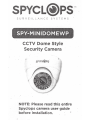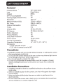
1
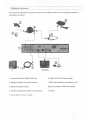
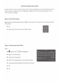
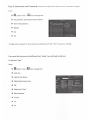
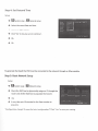
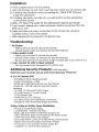
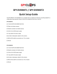
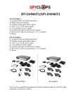
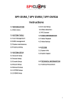
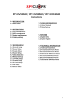
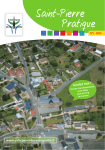
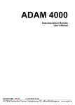
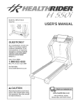
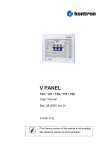
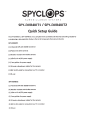
SPYCL@PS™
SURVEILLANCE
SYSTEMS
SPY-.DVR4K.IT1/ SPY-DVR4KIT2
Quick Setup Guide
The SPV-DVR4KIT1 I SPV-DVR4KIT2 are a complete home surveillance kit that has everything needed for
a simple plug-n-play operation. Below is the list of components that come in the kits:
SPY-DVR4KIT1
(1) 4 channel DVR with 500GB Hard Drive
(2) Plastic mini dome cameras
(2) Weather resistant mini bullet cameras
(1) 12bv tb...12v AC/DC power supply
(1) 5 way splitter for power supply
(4) 18 meter video/power cables for the cameras
(1) BNC to RCA cable for connection to a TV or monitor
(1) Ml.use
SPY-DVR4KIT2
(1) 4 channel DVR with 500GB Hard Drive
(4) Weather resistant mini bullet cameras
(1) 120v to 12v AC/DC power supply
(1) 5 way splitter for power supply
(4) 18 meter video/power cables for the cameras
(1) BNC to RCA cable for connection to a TV or monitor
(1) Mouse
I Making the Connections
Once you have unpacked the equipment and found a suitable location for the DVR, begin making the
connections as follows:
TV
MONITOR
1. 4 channel DVR with 500GB Hard Drive
6. 120v to 12v AC/DC power supply
2. Weather resistant mini bullet cameras
7. BNC to RCA cable for connection to a TV
3. Plastic mini dome cameras
(VGA to a monitor-VGA not included)
4. 18 meter video/power cables for the cameras
8. Mouse
5. S-way splitter for power supply
SPYCLOPS BASIC DVR SETUP
All steps are given in order as if from home screen. If after completing a step and returning to the home
screen you see a message that says "Configuration changed! To save the latest configurationrCiick
"Yesnto save your settings.
Step 1: First Time Log In
Right click on mouse for Setup (screen will display "Username' and "Password', do not enter any text in
this window).
-+
OK.
-+
Setup (you will now see the main Setup screen).
Step 2: Format the Hard Drive
Setup
-+ 12:1 System Tools-- D HOD management
-+
Check "v" the Format box.
-+
Select the Format button.
-+
Click "Yes" to the 'Are you sure to continue' popup.
-+
It may take a few minutes for the hard drive to format.
-+
Ok.
-+
Ok.
Step 3: Username and Password (Password is required for remote access in browsers or apps)
Setup
-+ r£1 System Tools -- ~ User management
-+
Set password, (Old password leave blank).
-+
Enter new password.
-+
-+
-+
Repeat.
Ok.
Ok.
"Configuration changed! To save the latest configuration?" Click" Yes" to save your settings.
If you want the Use rna me to be different than "admin" you will need to add user.
To add new "User'
Setup
-+
-+
..
System Tools--
i:J User management
Add User.
-+
-+
Type in User Name.
-+
-+
-+
-+
-+
-+
OK.
Select User Access Level.
Select new "User".
New Password.
Repeat.
Ok.
Ok.
I
Step 4: Set Date and Time
Setup
-+ ~System setup -fiD General setup
-+
-+
-+
-+
-+
Select the correct Date and time.
Click the 'Apply' button.
Click 'Yes' to 'Are you sure to continue'.
Ok.
Ok.
To generate the Esee 10 the DVR must be connected to the network through an Ethernet cable.
Step 5: Basic Network Setup
Setup
-+ fi1 System setup - Ia Network setup.
-+
Check the DHCP box to dynamically assign an IP through the
router and click the Esee box to populate the Esee 10.
-+
-+
Ok.
It may take up to 10 minutes for the Esee number to
populate.
"Configuration changed! To save the latest configuration?" Click" Yes" to save your settings.
Step 6: Access the DVR from a browser connected to the same network
Setup
-+ ~System setup -Ia Network setup -- make note of
SPYCL@PS'"
your DVR IP address and Esee number.
-+
In a web browser in the same network, enter the IP
address you just took note of from the DVR.
-+
-+
Accept the pop up and install Active X controls.
Enter the username and password for the DVR in the log
Peace of Mind
... ,.....~ .....-.~~n-~
6t-,..,~_,
in screen and select the Jog in button.
Step 7: Setup Recording
Setup
-+ IJ System setup- B Record setup
-+ Pick the channel and day of the week you want to record.
+ Choose Time,
or Sensor for the recording mode.
1t1
*Note: Sensor recording not currently supported.
-+
Click Copy to if you want to copy the setting to another channel or to all other channels.
-+
Ok.
NConfiguration changed/ To save the latest configurationr Click "Yes" to save your settings.
R£MOTE
SURVEIUAHCE
ACCESS
Step 8: Video Playback
-+ Setup - ~ Video Playback
-+
Pick the channel you want to play back.
-+
Choose Time, Vntio·• or Sensor for the recording mode.
*Note: Sensor playback not currently supported.
-+
Enter the record time and hit Search.
-+
Select the recording block in which you want to view and click playback.
For more detail instructions such as setting up the Spyclops DVR, Network settings, Recording settings,
and info about the free Smartphone app, please visit our website: www.spyclopsusa.com
For live Technical Support assistance M-F I 9-6 please call 866.839.9187 Ext 2393
Email: [email protected]
SPYCL@PS~
SURVEILLANCE
SYSTEMS
METRA HOME THEATER GROUP
460 Walker Street, Holly Hill, Fl32117
866.839.9187
metrahometheatergroup.com
PS™
SURVEILLANCE
SYSTEMS
.
.~
SPY-MINIBULL ETG'
CCTV Indoor/Outdoor
Security Camera
NOTE: Please read this entire
Spyclops camera user guide
before installation.
SPY-MINIBULLETG
FeatureS":
Imaging Device
1/4" CMOS
Lens
Chipset
SPY-UTC Compatable
Fixed 3.6mm
8510A
No
Viewing angle (Horizontal view)
44°
700 TVL
Resolution
720(H) X 480(V)
Effective Pixels (NTSC)
720(H) X 576(V)
PAL Pixels
Minimum illumination
0.001 Lux
F Stop
F1.2
Infrared LEDs
24 Smm IR LEDs
20 Meters (66 feet)
IR Distance
Motion Detection
No
Privacy Masking
No
IP66
Dust/Water Protection
DC12V (tlO%)
Power Source
Current Consumption
400mA
14° -122° F ( -10°- 50° C)
Operating Temperature
Dirnensions
• 7.25" long (camera and mount straight including sun shield),
• 3" tall (from bottom of mounting base (at 90 2 angle) to top of camera),
• 2.875, wide (width of sunshield)
Precautions:
1. Handle the camera with care. Avoid hitting, dropping, or shaking the camera
otherwise damage could occur.
2. Do not aim the camera directly at the sun or other very intense light source
since damage could occur to the image sensor.
3. Do not submerge the camera into water.
4. Do not try to dissemble the camera which could let in water or foreign
objects. Damage could occur to the camera and cause fire or electrical
shock
Installation Precautions:
1. Installation should be done by a qualified technician so to conform to any
local codes.
2. Select a suitable location for the camera; one that will support the weight
of the camera. _
3. Make sure before drilling holes there are no water or gas lines and no
electrical wires.
4. Do not mount the camera near a heat source, somewhere that would have
strong vibrations, or a strong magnetic field.
Installation:
1. Find a suitable location for the camera
2. Hold camera base up and mark mounting holes where you are going to drill.
3a. If drilling into sheetrock, wood, or paneling etc ... Drill a 9/32" hole and
insert the wall anchor
3b. If drilling into block, concrete, etc ...you will need to use the appropriate
screw and/or anchor
·
4. Drill a .75" hole in the center for the video/power cable to go through
5. If you haven't already ran a video and power cable to the-camera from the
DVR, do so now
·
6. Make the video and power connections to the camera then using the
supplied screws, mount the camera.
7. Make adjustments to camera for the desired view.
Troubleshooting:
1. No Picture
• Make sure you have 12 volts at the camera
• Double check video connections for bad terminations
2. Video quality is bad
• Make sure you have 12 volts at the camera.
• Double check video connections for bad terminations
• Be sure the camera isn't pointed at a high intensity light source like the sun.
3. Can I connect 24 volts to these cameras?
• No, the cameras are designed for 12 volt DC only
Additional Security Products: <sold seperately)
Optimize your security set up with these Spyc/ops Products!
4, 8 or 16 Channel DVR
• Embedded LINUX Operating System
• Image Compression - H.264
• Stores Up to 28.8 MB Audio Per Hour Per Channel
• Stores 80 - 250 MB Video Per Hour Per Channel
Hardware:
• (1) HDMI, (1) VGA, and (1) BNC Output .
• (2) Audio Inputs I (1) Audio Output
• CAT6 Network Port
• RS485 Port for PTZ Cameras
• (2) USB 2.0 Ports (for USB Backup and Mouse)
• Includes 12 Volt 3 Amp Power Supply and Mouse
~
S-Way, 9-Way or 18-Way Power Distribution
• 110 Volt to 12 Volt Power Supply
• Lockable Door - Includes Two Keys
• Status LED is On When 12 Volt Power Supply is On
• LED is Off When There is No Power from the Power Supply
• 1 AMP PTC Fuses Protect the Cameras
• Removable Power Connections Make Wiring Cameras Easier
• Rubber Grommets Included to Run Wires Through
• Knockouts on Top and Side of Power Supply Box
• Available in 5, 9 and 18 Way Distribution
SPYCLOPS Limited Warranty:
This limited warranty is provided by Metra Electronics Corporation for the "SPYCLOPS"
product iden~fied by the purchaser's registration as indicated below, and there are no
other warranties, expressed or implied,. except as required by law, including warranties
of merchantability and fitness for a specific purpose, that are prov.ided for' herein,
however all such implied warranties, if any, are limited to the duration of this specific
limited product warranty. Some states do not allow limitations on how. long an implied
warranty lasts, so the above limitations may not apply to you.
Metra Electronics Corporation shall not be liable, ,under any circumstances, for
incidental, indirect, special, consequential or multiple damages as a result of the sale
or use of this product.
Due to the nature of this electronic product which may be used in a varierty of
applications, the purchaser must register this product with Metra Electronics
Corpoation, either by returning the enclosed registration card or registering on line. It
is recommended that the purchaser execute and deliver the enclosed registration and
warranty card within ten days of purchase.
Limited Product War~anty:
This is a limited warranty, subject to the conditions, limitations and exclusions identified
herein. Metra Electronics Corporation warrants to the original purchaser of the
registered or identified SPYCLOPS product for a period of three years from the date of
purchase, that the product shall be free of defects in design, material and workmanship,
and subject to the limitations set forth below, Metra Electronics Corporation will repair
or replace, at its option, any defective unit.
Conditions and Limitations:
1. Proof of purchase is required (i.e. the sales receipt of other proof of payment)
2. Damage caused by disassembly, accidents, abuse, misuse or modification of the
product win render this warranty null and void.
3. This warranty is applicable only to the original purchaser and is not assignable or
transferable.
4. The purchaser is required to send the product back to Metra Electronics Corp. in
accordance with the instructions set forth on the enclosed Warranty card and the
purchaser is responsible for all charges for shipping and handling. Please note
that in accordance with the instructions on the enclosed Warranty Card, that the
__ product must be returned to Metra Electornics with an assigned Authorization
number (RA).
Any questions of Notification~ regarding this warranty should be addressed to: Warranty
Department, Metra Electronics'torporation, 460 Walker St., Holly, Hill, Florida, 32117.
S U R V E I L L A N C E
S Y S T':<E M S
"- ·
c
.
866.839.9187 - ~
460 Walker Street, Holly Hill, FL 32117
www.spyclopsusa.com
PS™SURVEILLA. NCE
SYSTEMS
SPY-MINIDOM EWP
CCTV Dome Style
Se~urity Camera
/
NOTE: Please read this entire
Spyclops camera user guide
before installation.
SPY-MINIDO MEWP
~
Features~
1/4" CMOS HDIS
Imaging Device
Fixed 3.6mm
Lens
8510A
Chipset
No
SPY-UTC Compatable
440
Viewing angle (Horizontal view)
700 TVL
Resolution
720(H) X 480(V)
Effective Pixels (NTSC)
976(H) X 582(V)
PAL Pixels
0.001 Lux
Minimum illumination
F1.2
F Stop
24 Smm IR LEDs
Infrared LEDs
20 Meters (66 feet)
IR Distance
·No
Motion Detection
No
Privacy Masking
N/A
Dust/Water Protection
DC12V (:tlO%)
Power Source
400mA
Current Consumption
14° -122° F ( -10°- 50° C)
Operating Temperature
Dimensions
• 3.625" diameter at base
• 3.25" tall w/ camera turned at 90°
Precautions:
1. Handle the camera with care. Avoid hitting, dropping, or shaking the camera
otherwise damage could occur.
2. Do not aim the camera directly at the sun or other very intense light source
since damage could occur to the image sensor.
3. Do not submerge the camera into water.
4. Do not try to dissemble the camera which could let in water or foreign
objects. Damage could occur to the camera and cause fire or electrical
shock
Installation Precautions:
1. Installation should be done by a qualified technician so to conform to any
local codes.
2. Select a suitable location for the camera; one that will support th~ weight
of the camera.
3. Make sure before drilling holes there are no water or gas lines and no
electrical wires.
4. Do not mount the camera near a heat source, somewhere that would have
strong vibrations, or a strong magnetic field.
lnsta.l lation:
1. Find a suitable location for the camera
2. Hold camera base up and mark mounting holes where you are going to drill.
. 3a. If drilling into sheetrock, wood; or paneling etc ... Drill a 9/32JJ hole and
insert the wall anchor-3b. If drilling into block, concrete, etc ...you will need to use the appropriate
screw and/or anchor
4. Drill a .75" hole in the center for the video/power cable to go through
5. If you haven't already ran a video and power cable to the camera from the
'
DVR, do so now
6. Make the video and power connections to the camera then using the
supplied screws, mount the camera.
7. Make adjustments to camera for the desired view.
Troubleshooting:
1. No Picture
.
• Make sure you have 1~ volts at the camera
• Double check video connections for bad terminations
2. Video quality is bad
• Make sure you have 12 volts at the camera.
• Double check video connections for bad terminations
• Be sure the camera isn't pointed at a high intensity light source like the sun.
3. Can I connect 24 volts to these cameras?
• No, the cameras are designed for 12 volt DC only
Additional Security Products:
<sold seperately)
Optimize your security set up with these Spyc/ops Products!
4, 8 or 16 Channel DVR
•
•
•
•
Embedded LINUX Operating System
Image Compression - H.264
Stores Up to 28.8 MB Audio Per Hour Per Channel
Stores 80 - 250 MB Video Per Hour Per Channel
Hardware:
• (1) HDMI, (1) VGA, and (1) BNC Output
• (2) Audio Inputs I (1) Audio Output
• CAT6 Network Port
• RS485 Port for PTZ Cameras
• (2) USB 2.0 Ports (for USB Backup and Mouse)
• Includes 12 Volt 3 Amp Power Supply and Mouse
S-Way, 9-Way or 18-Way Power Distribution
• 110 Volt to 12 Volt Power Supply
• Lockable Door - Includes Two Keys
• Status LED is On When 12 Volt Power Supply is On
• LED is Off When There is No Power from the Power Supply
• 1 AMP PTC Fuses Protect the Cameras
• Removable Power Connections Make Wiring Cameras Easier
• Rubber Grommets Included to Run Wires Through
• Knockouts on Top and Side of Power Supply Box
• Available in 5, 9 and 18 Way Distribution
SPYCLOPS Limited Warranty:
This limited warranty is provided by Metra Electronics Corporation for the "SPYCLOPS"
product identified by the purchaser's registration as indicated below, and there are no
other warracsties, expressed or implied, except as required by law, in~luding warranties
of merchantability and fitness for .a specific. purpose, that are provided for hereiA,
however all such implied warranties, if any, are limited to the duration of this specific
limited .product warranty. Some states do not·allow limitations on how long an implied
.
•
warranty lasts, so the above lim!tations may not apply to you.
Metra Electronics Corporation shall not be liable, under any cirtumstances, for
incidental, indirect, special._ consequential or multipte·damages as a·result of the sale
or use of this product.
·
·
.
·
· ...• · ·
·
.
Due to 'the nature of this electronic product which may be used in a Vqrierty of
applications, the purchaser must register this product with Metra Electronics
Corpoation, either by returning the enclosed registration card or registering on line. It
is recommended that the purchaser execute and deliver the enclosed registration and
warranty card within ten days of purchase.
Limited Product Warranty:
•
·
This is a limited warrantY, subject to the conditions·, limitations an-d exclusion~ identified
herein. Metra Electronics Corporation warrants to the original purchaser of the
registered or identified SPYCLOPS product for a period of three years from the date of
purchase, that the product shall be free of defects in design, material and workmanship,
and subject to the limitations set .forth below, Metr~ Electronics Corporation will repair
or replace, at its option, any def8:tive unit.
Conditions aoo Limitations:
.
1. Proof of purchase is required (i.e. the sales receipt of. other proof of payment)
2. Damage caused by disassembly, accid~nts, abuse~ ·misu!e or modification of the
product will render this warranty null and void.
'
3. This warranty is applicable only to the original purchaser and is not assignable or
transferable.
..
4. The purchaser is required to send the product back to Metra Electronics Corp. in
accordance with the instructions set forth on the enclosed Warranty card and the
purchaser is responsible for all charges for shippi~g and handling. . Please note
that in accordance with the instructions on the enclosed Warranty Card, that the
product must be returned ·to Metra Electornics with an assigned Authorization
number (RA).
Any questions of Notifications regarding this warranty should be a.ddressed to: Warranty
Department, Metra EJectronics Corporation, 460 Walker St,...Ho·Uy, Hill, Florida, 32117.
SURVEILLANCE
~
SYSTEMS
.
866.839.91!7
460 Walker Street, Holly Hill, FL 32117
www.spyclopsusa.com