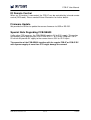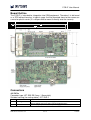
1
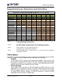
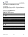
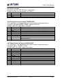
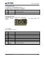
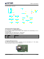
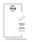
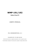
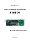
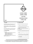
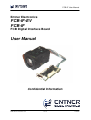
FCB-IF User Manual
Entner Electronics
FCB-IF-EV
FCB-IF
FCB Digital Interface Board
User Manual
Confidential Information
www.entner-electronics.com
1 of 16
1.0/2014
FCB-IF User Manual
Introduction
The FCB-IF-EV and FCB-IF (FCB Interfaces) are interface boards used to provide
both DVI and USB support for Sony FCB-EV, FCB-EH and FCB-SE camera module
series. Support for FCB-EX1020P is available on request.
Special features are frame rate doubling / multiplication, flash triggering and pushbutton / OSD control of the camera.
Output resolutions up to 1080p60 (1920 x 1080, “Full-HD”) are supported. Interlaced
modes are not supported. The FCB-IF-EV supports also the new 1080p50/60 modes
of the FCB-EV series.
The FCB-IF-EV features optional aberration correction and temporal noise reduction
to boost image quality.
Features
o Interface to digital output (30pos LVDS connector) of Sony cameras FCB-EV
and FCB-EH series and FCB-SE600
o Provides DVI output up to 1080p60
o Provides frame rate doubling / multiplication on DVI output (up to 1080p60)
o Provides USB 2.0 interface (480Mb/s)
o
o
FCB-IF-EV: Supports aberration correction for many modules like FCB-EH6300,
FCB-EV7500, etc.
FCB-IF-EV: Supports temporal noise reduction
o Optional SD Card interface to store images without the need for a PC*
o Optional support for synchronized flash triggering
o Can translate UVC commands, SPEED commands (RS-232) and pushbuttons into VISCA protocol
o OSD (On Screen Display) menu for convenient camera setup
o Also supports VISCA pass-through mode
o Firmware updates via USB or RS-232
o Custom modifications and extensions possible
Applications
o
o
o
o
o
Visual inspection
Medical
Machine Vision
High-End Surveillance
Others
* not available for passport, ID card and money inspection applications
www.entner-electronics.com
2 of 16
1.0/2014
FCB-IF User Manual
Supported Cameras, Resolutions and Frame Rates
Resolutions on DVI-D out and USB 2.0 out with FCB HD cameras
Camera Setting
1080p/60 1080p/50 1080p/30 1080p/25 720p/60 720p/50 720p/30 720p/25
DVI-D out
1080p/60 1080p/50 1080p/60 1080p/50 720p/60 720p/50 720p/60 720p/50
USB 2.0 out
1080p/20 1080p/25 1080p/30 1080p/25 720p/60 720p/50 720p/60 720p/50
FCB-EV7500
x (EV)
x (EV)
x
x
x
x
x
x
FCB-EV7310
x (EV)
x (EV)
x
x
x
x
x
x
FCB-EV7300
x (EV)
x (EV)
x
x
x
x
x
x
FCB-EV7100
x (EV)
x (EV)
x
x
x
x
x
x
FCB-EH6500
x
x
x
x
x
x
FCB-EH6300
x
x
x
x
x
x
FCB-EV5500
x
x
x
x
FCB-EV5300
x
x
x
x
FCB-EH3400
x
x
x
x
FCB-EH3410
x
x
x
x
FCB-EH3300
x
x
x
x
FCB-EH3310
x
x
x
x
FCB-EH3150
x
x
x
x
x
x
x
x
FCB-SE600 (5V)
x
x
Note 1:
x (EV): Supported by FCB-IF-EV only
x: Supported by FCB-IF and FCB-IF-EV
Note 2:
The FCB-EV7x00 use 59.95/29.97Hz instead of 60/30Hz. For support
of these frequencies for other cameras, please contact Entner Electronics.
Note 3:
Interlaced modes are not supported by default.
If required, please contact Entner Electronics.
Note 4:
The FCB-SE600 requires 5V supply. Please see section ”Special Note Regarding
FCB-SE600” for details.
VISCA Modes
The FCB-IF supports three different modes of operation which decide how the VISCA
interface is used. The VISCA mode can be set through the OSD menu:
o NORMAL
In this mode, FCB-IF controls the camera over VISCA. The user can use
push-buttons connected to the FCB-IF, RS-232 (“SPEED”), USB and the OSD
to control the camera. User settings are stored in an EEPROM of the FCB-IF
and are transferred to the camera at every startup.
o PASS-THROUGH
In this mode, FCB-IF connects its RS-232 interface to VISCA interface. A user
application has to control the camera via VISCA. FCB-IF itself has no control
over the camera and just converts the image data. The OSD can just be used
to setup FCB-IF specific settings. As RS-232 interface is used for VISCA
commands, FCB-IF control is not possible.
www.entner-electronics.com
3 of 16
1.0/2014
FCB-IF User Manual
o SNOOP
This is a setting for very specific applications that should not be used by
regular users.
Initial Setup of the FCB-IF-EV and FCB-IF
Hardware Setup
o Connect FCB-camera with the 30pos cable to J42 connector of the FCB-IF
o Connect the monitor to J4 connector (DVI)
o Connect the keypad for OSD control to J34 connector (JST B13B-ZR)*
o Connect the 12V supply to J41 connector (JST B2B-ZR)*
* We also provide a dedicated board with a DC connector and push-buttons to interface to these
connectors
Steps for Initial Setup
o Press Menu button, OSD should appear on the monitor
o Navigate to Device Settings and press Left or Right to enter sub-menu
o Ensure that VISCA Mode is set to NORMAL
o Ensure that VISCA Baud rate matches the camera setting (9600 by default)
o Select the correct camera model. (If your specific camera is not supported, try
to select a similar model or contact Entner Electronics to integrate it in the
firmware.)
o If it was necessary to change any of these settings, power-cycle and press
Menu again, otherwise navigate to Return and press Left or Right
o Navigate to Resolution Settings and press Left or Right
o Navigate to the desired resolution and select it by pressing Left or Right. As
we are in normal VISCA mode, this will update the resolution of both the FCBIF output and the camera.
o Finally the camera image should appear on the monitor.
Color Codes
During startup and in case of a problem the FCB-IF gives an indication by a full
screen color on the DVI output. These colors have the following meanings:
o Dark blue
System just started up, the FCB-IF is waiting for an image signal from the
camera.
o Light blue
Current models of FCB camera generate this color during initialization – it is
not generated by FCB-IF. The real image should appear within seconds.
o Dark red
No valid image signal detected. Most commonly caused by failure of the 30pos
connection cable or another hardware problem.
o Green
Valid image signal is recognized, but it does not match the expected resolution
or frame rate. It is also possible that a wrong camera model is selected, as
signaling has changed between FVB-EH and FCB-EV series. You might want
to perform the initial setup steps described in the section above.
www.entner-electronics.com
4 of 16
1.0/2014
FCB-IF User Manual
Operating the Camera with Push-Buttons
Hardware Setup
o Connect FCB-camera with the 30pos cable to J42 connector of the FCB-IF
o Connect the monitor to J4 connector (DVI) or PC to J27 connector (Mini-USB)
o Connect the keypad to J34 connector (JST B13B-ZR)*
o Connect the 12V supply to J41 connector (JST B2B-ZR)*
* We also provide a dedicated board with a DC connector and push-buttons to interface to these
connectors
Zooming
Use the Zoom Tele and Zoom Wide buttons to change the zoom position. After the
end of the optical zoom, the digital zoom is automatically activated.
Focusing
Use the Focus Near and Focus Far buttons to change the focus position (manual
focus). This will automatically disable the auto focus. To enable (or disable) the AF,
press the AF button. (Exact behavior depends on the AF mode selected in the OSD
menu).
Auto Exposure (Iris, Shutter and Gain)
AE settings can be changed in the OSD menu. In the current firmware, the AE key is
not supported. However, pressing it for 2 seconds will trigger a white balance.
Freeze
Use the Freeze button to enable or disable freezing of the image.
Function Keys
When outside the menu, four function keys (F1 to F4) can be used for special
functions. By default, F1 to F4 are assigned to a preset function: By pressing Fx for
two seconds, the current camera settings are stored into the respective preset x. By
pressing Fx quickly, the previously stored settings are recalled.
You can also assign alternative behavior to the function keys through the OSD menu.
On Screen Menu
The on screen menu is likely to be extended in the future and the operation is mostly
self-explanatory. Therefore, only the basic functionality will be explained in this
manual.
Navigating in the Menu
Use the Menu button to enable or disable the menu. In the menu, every line
represents either a setting to change or a sub-menu. By using Up and Down buttons
you can select a line in the menu; by using Left and Right buttons you can
change/select the setting or enter the sub-menu. Every change is immediately
effective.
www.entner-electronics.com
5 of 16
1.0/2014
FCB-IF User Manual
Changing the resolution
The resolution can be changed in the Resolution sub-menu. Be sure that you have
selected the correct camera model first under “Device Settings”. The current
resolution is indicated in the head-line of the Resolution sub-menu. In order to
activate a different resolution, simply move the cursor to the desired line and press
Left or Right. When the VISCA-mode is set to NORMAL, the change will affect both
the FCB-IF as also the camera itself. However, when the PASS-THROUGH mode is
used, the FCB-IF cannot access the camera and therefore cannot change its
resolution. It is important that the camera’s output format matches the selected FCBIF resolution. A mismatch will be indicated by a green output screen.
The camera’s native resolution will always match the selected output resolution,
which means that in e.g. SVGA a smaller sensor area is read out than in e.g. UXGA.
Therefore also a different object size will be displayed at the same zoom position.
The resolution via USB can be selected by the PC application – it is either the full or
half of the selected resolution in the menu. When the resolution is changed in the
menu, the camera will re-enumerate on USB to present the new possible resolutions
to the host. It is possible to use USB and DVI output at the same time.
Other OSD Settings
Most other OSD settings are self-explanatory. As they might change with future
firmware versions they are not explained in detail here at this time. In case of any
doubt, please contact Entner Electronics.
RS-232 Interface (SPEED/VISCA)
In NORMAL VISCA mode, the camera supports the SPEED protocol (Serial Protocol
for Entner Electronics Devices). For details see the SPEED specification. The FCB-IF
will translate the SPEED commands to the respective VISCA commands. For a list of
supported SPEED commands please contact Entner Electronics. Also a demo
application (“Speed Control”) is available on request.
If VISCA mode is set to pass-through, the FCB-IF directly connects its RS-232
connection to the VISCA interface of the camera (level translation is performed by
hardware). Sony FCB ControlHD software or a dedicated user application can then
be used to control the camera.
USB Video Class (UVC) Device
The FCB-IF is USB Video Class (UVC) compliant. Therefore the camera is “Plug &
Play” compliant under Win XP SP2 and newer. No driver installation is necessary. If
you want to use the camera in a custom application, it can be easily accessed by
using a DirectShow filter. As the standard Windows MJPEG decoder is relatively
slow, one can be consider to install a commercial MJPEG decoder to the computer
(e.g. from www.morgan-multimedia.com).
UVC devices are also supported under recent Linux versions.
www.entner-electronics.com
6 of 16
1.0/2014
FCB-IF User Manual
For Windows we can provide an example application called “LUCY Viewer”.
Aberration Correction (FCB-IF-EV only)
The FCB-IF-EV supports aberration correction (i.e. colored borders on black and
white edges because of optical limitations of the lens are digitally reduced). With the
current firmware (V0.90a) correction tables for FCB modules with 3x, 20x and 30x
lenses are supported. Other cameras will be supported upon request. It is also
possible to provide custom correction tables for user supplied close-up lenses.
As the aberration correction is zoom position dependent, the FCB-IF needs to know
the zoom position of the camera lens. In normal operation mode this is handled in the
background by the FCB-IF firmware, however in pass through operation mode, the
use needs to activate the CAM_ContinuousZoomPosReply feature via the VISCA
command 81 01 04 69 02 FF at a sufficient high time interval (set e.g. with 81 01 04
6A 00 00 00 04 FF). The FCB-IF will monitor the zoom position replies of the camera.
(Of course the correct VISCA baudrate needs to be set in the OSD menu.
It should be understood that chromatic aberration can often not be removed
completely by the correction, but it will typically be a great improvement compared to
the uncorrected image.
The aberration correction feature can be enabled (AUTO) and disabled (OFF) in the
OSD menu (Image Settings -> Aberration Correction). (The MANUAL setting is only
intended for debugging / demonstration purposes.)
Temporal Noise Reduction (FCB-IF-EV only)
The FCB-IF-EV supports temporal noise reduction. By filtering over several frames,
the image noise can be greatly reduced. To avoid motion artefacts the filtering is
automatically disabled when motion is detected in the image. (This mode is intended
for applications with often objects like visual part inspection.)
Several strengths from OFF to 3 can be selected in the OSD menu (Image Settings > Temporal Noise Reduction). A setting of 2 has shown good results in many
applications.
SD Card Interface
By using an optional add-on board, snapshot images can be stored to an SD Card (in
JPEG format). For further details please contact Entner Electronics.
Flash Support
The FCB-IF can optionally support the triggering of an external flash. Due to the
rolling shutter sensor used in the FCB-EH cameras this works best in environments
with dark ambient light. For further details please contact Entner Electronics.
www.entner-electronics.com
7 of 16
1.0/2014
FCB-IF User Manual
IR Remote Control
When an IR receiver is connected, the FCB-IF can be controlled by infrared remote
control (RC5-code). Please contact Entner Electronics for further details.
Firmware Update
We provide the utilities to update the camera firmware via USB or RS-232.
Special Note Regarding FCB-SE600
Unlike other FCB cameras, the FCB-SE600 requires 5V to 5.5V supply. This can be
achieved by either operating the FCB-IF with 5.3V +/- 0.2V or by using the FCB-IF5V which will provide 5V supply to the camera from a 5.5V to 13.2V input.
The operation of the FCB-SE600 together with the regular FCB-IF or FCB-IF-EV
with a power supply of more than 5.5V might damage the camera!
www.entner-electronics.com
8 of 16
1.0/2014
FCB-IF User Manual
Board Outline
The FCB-IF is intended for integration into OEM equipment. Therefore it is delivered
as a PCB without housing. In typical usage it will be mounted close to the camera on
a metal or plastic carrier (it is not possible to mount it directly onto the camera).
Connectors
J41 DC In
Connector type: JST S2B-ZR (2way, 1.5mm pitch)
Suitable housing (for mating cable): JST ZHR-2
Pin
Name
Comment
1
+12V typ.
2
GND
www.entner-electronics.com
Positive connection to power supply, 6.0VDC to 13.2VDC , also used for
camera (which may have more restricted requirements)
Ground (negative) connection to power supply
9 of 16
1.0/2014
FCB-IF User Manual
J4 DVI Output
Industry standard DVI-D connector for digital monitor connection.
J27 USB Interface
Industry standard Mini-USB connector (Mini-B type). The location of the connector is
on the bottom side of the PCB. As it might not be well suited for some applications, it
is possible to route it to a different location with a simple add-on PCB. For details
please contact Entner Electronics.
J42 Interface to Camera FCB-EV/EH/SE series
Connection to the camera.
Connector type: USL00-30L (KEL Corp.)
Suitable housing: USL20-30S (KEL Corp.)
Pin
Name
Comment
1
RXIN3+
2
RXIN33
RXCLKIN+
4
RXCLKIN5
RXIN2+
6
RXIN27
RXIN1+
8
RXIN19
RXIN0+
10
RXIN011
GND
12
VISCA_RXD
13
VISCA_TXD
14
DC OUT
15
DC OUT
16
DC OUT
17
DC OUT
18
DC OUT
19
GND
20
GND
21
GND
22
GND
23
GND
24
GND
25
AF_BUTTON*
26
RESET_OUT
27
FOCUS_FAR_BUTTON*
28
FOCUS_NEAR_BUTTON*
29
ZOOM_WIDE_BUTTON*
30
ZOOM_TELE_BUTTON*
* Open collector outputs to simulate
current firmware.
www.entner-electronics.com
RXIN[3..0]: 4 LVDS pairs for digital video input
LVDS pair with clock for RXIN[3..0]
To TxD of camera (Signal level compatible with supported cam.)
To RxD of camera (Signal level compatible with supported cam.)
Power supply to camera
(From FCB-IF power-supply input, with polarity and
overvoltage protection)
Attention! Some cameras might require a +5V supply. Contact
Entner Electronics for special version of FCB-IF with +5V output.
Optional. Supported only by some cameras.
Optional. Reset input is only supported by some cameras.
Optional. Supported only by some cameras.
Optional. Supported only by some cameras.
Optional. Supported only by some cameras.
Optional. Supported only by some cameras.
key presses to camera (input on camera side). Not supported by
10 of 16
1.0/2014
FCB-IF User Manual
J38 RS-232 Interface
Connector type: JST S3B-ZR (3way, 1.5mm pitch)
Suitable housing (for mating cable): JST ZHR-3
Pin
Name
Comment
1
2
3
RxD (of device)
TxD (of device)
GND
Connect to TxD of controller (or previous device when chaining is used)
Connect to RxD of controller (or next device when chaining is used)
For further details, see SPEED specification.
J43 Control Interface to Camera FCB-EX1020P
(This connector is not supported by the current firmware, please contact us)
Connector type: 00 6200 509 130 000+ (Kyocera Elco Co.)
Suitable cable: FFC cable 9pos, 1mm pitch
Pin
Name
Comment
1
2
3
4
5
6
7
8
VISCA_TXD
VISCA_RXD
GND
DC OUT
GND
NC
GND
V_LOCK_OUT
9
GND
To RxD of camera (Signal level compatible with supported cameras)
To TxD of camera (Signal level compatible with supported cameras)
Power supply of camera (from FCB-IF power supply input)
Not connected
Opt. VD Lock sync pulse output to camera (Signal level compatible with
supported cameras)
J44 Video Interface to Camera FCB-EX1020P
(This connector is not supported by the current firmware, please contact us)
Connector type: 1-1734592-2 (Tyco)
Suitable cable: FFC cable 12pos, 0.5mm pitch
Pin
Name
Comment
1
2
3
4
5
6
7
8
9
10
11
12
GND
DIG_IN0
DIG_IN1
DIG_IN2
DIG_IN3
DIG_IN4
DIG_IN5
DIG_IN6
DIG_IN7
GND
CLOCK_IN
GND
www.entner-electronics.com
Digital video input for camera image (8bit parallel)
For EMC and signal integrity reasons, an as short as possible
FFC cable is recommended.
(Signal level compatible with supported cameras)
Clock input for digital video input
11 of 16
1.0/2014
FCB-IF User Manual
J37 Optional IR Input
(This connector is not mounted by default)
Connector type: JST S3B-ZR (3way, 1.5mm pitch)
Suitable housing (for mating cable): JST ZHR-3
Pin
Name
Comment
1
+3V3
2
3
IR-Receiver
GND
For connection of Vishay TSOP34836 or compatible (use 4.7uF
decoupling/filter capacitor)
For connection of Vishay TSOP34836 or compatible
J34 Keypad Interface
Connector type: JST S13B-ZR (13way, 1.5mm pitch)
Suitable
housing
ZHR-13
(for mating cable): JST
LUCY Keypad
(can be used for evaluation)
Pin
Name
Comment
1
2
3
4
5
6
7
8
9
10
11
12
ROW1
ROW2
ROW3
ROW4
COL1
COL2
COL3
IR-Receiver
GND
AF LED
AE LED
+3V3 for IRReceiver
Reserved
For 4 x 3 key-matrix
(See schematic below)
13
www.entner-electronics.com
For connection of Vishay TSOP34836 or compatible
Active high (3.3V), 100R resistor inside the camera
Active high (3.3V), 100R resistor inside the camera
For connection of Vishay TSOP34836 or compatible (use 4.7uF
decoupling/filter capacitor)
12 of 16
1.0/2014
FCB-IF User Manual
Key connection schematic:
J45 Optional Flash Trigger Output
(This connector is not mounted by default)
(This connector might also be used for other purposes like connecting a fan as
firmware option)
Connector type: JST S2B-ZR (2way, 1.5mm pitch)
Suitable housing (for mating cable): JST ZHR-2
Pin
Name
Comment
1
2
+5V
Trigger output
+5V supply to e.g. drive an opto-coupler
Active low open collector trigger output
J1 Optional SD Card Interface
An SD Card Interface to store snapshots can be connected to J1. For further
information please contact Entner Electronics.
www.entner-electronics.com
13 of 16
1.0/2014
FCB-IF User Manual
Optional IR-Remote Control
An IR-Remote Control is available to control the interface / camera with the main
functions and the OSD menu. An IR receiver is mounted on the LUCY Keypad.
Furthermore the FCB-IF is prepared to connect an IR receiver to connector J34 or
J37.
Specifications of FCB-IF-EV and FCB-IF
Supported cameras
DVI connector
USB connector
Control options
Flash support
SD Card storage
Operating conditions
Storage conditions
Dimensions
Power supply
FCB-EV7500*, FCB-EV7300*, FCB-EV7320*, FCB-EV7100*,
FCB-EH6500, FCB-EH6300, FCB-EV5500, FCB-EV5300,
FCB-EH3400, FCB-EH3410, FCB-EH3300, FCB-EH3310,
FCB-EH3150, FCB-SE600 (5V)
(Others on request, in many cases just a firmware
update will be required.)
DVI-D, up to 1080p60
Mini-USB, type Mini-B (USB 2.0, 480MBit/s)
(For a different location, please contact Entner
Electronics)
USB, RS-232, IR, push-buttons
optional, for details please contact Entner Electronics
optional, for details please contact Entner Electronics
0°C to 45°C, 20 to 80% humidity (non-condensing)
-20°C to 60°C, 20 to 95% humidity (non-condensing)
88mm x 41mm x 17mm
6V to 13.2V DC, max. 5W + camera-power
* 1080p50/60 input from camera supported with FCB-IF-EV only
www.entner-electronics.com
14 of 16
1.0/2014
FCB-IF User Manual
Ordering Information
FCB-IF-EV
FCB-IF
FCB-IF-5V
FCB-IF-xxx
LUCY Keypad (FCB-IF)
LUCY IR Remote
SD-Card-IF
FCB-IF-EV-Demo*
FCB-IF-Demo*
FCB Interface (up to 1080p60 input resolution for FCBEV series)
FCB Interface (up to 1080p30 input resolution)
FCB Interface (up to 1080p30 input resolution) with 5V
camera supply (e.g. for FCB-SE600) from 5.5V to 13.2V
DC input. Please see section ”Special Note Regarding
FCB-SE600” for details.
FCB Interface with customized firmware and/or
hardware (assembly options) (xxx = number from 001 to
999)
Keypad for FCB-IF that can be used for evaluation
purposes, including connection cables (1x 2pos, 1x
3pos, 1x 13pos)
12 button infra-red remote control
SD Card Interface Board
Demo-Kit includes:
FCB-IF-EV
LUCY Keypad (FCB-IF)
Power Supply 9V or 12V
USB cable (A / Mini-B) for FCB-IF
USB cable (A / B) for virtual COM-port of keypad
Demo-Kit includes:
FCB-IF
LUCY Keypad (FCB-IF)
Power Supply 9V or 12V
USB cable (A / Mini-B) for FCB-IF
USB cable (A / B) for virtual COM-port of keypad
*You will require an FCB camera and the 30pos cable!
Safety and EMC
As the FCB-IF is intended to be used in OEM products, according tests should be
done with the final product. The FCB-IF was designed with EMC regulations in mind.
Custom Modifications
Since an FPGA based product is very powerful and flexible in general, it is likely that
custom features can be integrated into the existing design with reasonable effort.
Please contact Entner Electronics for further details.
www.entner-electronics.com
15 of 16
1.0/2014
FCB-IF User Manual
Precautions
The FCB-IF interface boards are sensitive electronic devices and should be handled
with the usual precautions. Especially take care on following points:
o Do not violate the specified operating and storage conditions
o Do not apply excessive force onto the PCB, the connectors and the lens
o If the DVI connector is accessible to the user, it is strongly recommended that
it is mounted into a metal panel, so that there is no force onto the PCB when a
connector is plugged/unplugged
o Keep the PCB clean and dry
o Follow the usual ESD handling precautions for electronic devices
o Keep the supply voltage in the specified range, also do not apply excessive
voltages to other connectors
o Do not touch the PCB with metal equipment, especially during operation,
because there is the danger of damaging the PCB (“short-circuit”)
o Do not use the product in situations with excessive vibrations
Revision History
Revision
0.1
0.2
Date
th
11 Feb. 2013
th
16 Sept. 2013
1.0
29 July 2014
th
Author
TE
UM / TE
TE
Remarks
Initial release (for pre-production firmware)
Extension with FCB-IF-EV
Aberration Correction, Temp. Noise Reduction, Support
for FCB-EV73x0, FCB-EV5x00
Confidential Information
Confidental information – specification and availability subject to change without notice
© 2014 Entner Electronics KG. All rights reserved. All product or service names are the property of their respective holders. Entner Electronics KG
assumes no responsibility or liability arising out of the application or use of any information, product, or service described herein expect as
expressly agreed to in writing by Entner Electronics KG.
Entner Electronics KG, Treietstr. 42,
6832 Sulz, AUSTRIA, Tel: +43 5522 75717-0
Internet: www.entner-electronics.com
e-mail: [email protected]
www.entner-electronics.com
16 of 16
1.0/2014