1
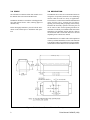
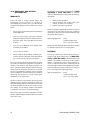
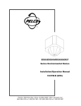
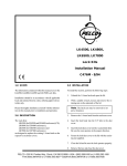
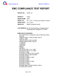
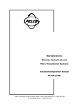
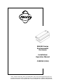
®
EH6500 Series
Environmental
Enclosure
Installation/
Operation Manual
C459M-E (1/96)
Pelco • 300 W. Pontiac Way, Clovis, CA 93612-5699 • USA • Pelco Online @ http://www.pelco.com
In North America and Canada: Tel (800) 289-9100 • FAX (800) 289-9150 • DataFAX (800) 289-9108
International Customers: Tel (1-559) 292-1981 or FAX (1-559) 348-1120 • DataFAX (1-559) 292-0435
TABLE OF CONTENTS
Section
Page
1.0
WARNINGS ........................................................................................................................................ 1
2.0
SCOPE ...............................................................................................................................................2
3.0
DESCRIPTION ................................................................................................................................... 2
4.0
INSTALLATION .................................................................................................................................. 3
4.1 BLOWER AND HEATER ELECTRICAL CONNECTION (IF APPLICABLE) ............................. 3
4.2 INSTALLATION OF CAMERA/LENS ........................................................................................ 6
4.3 ENCLOSURE MOUNTING - PAN/TILT .................................................................................... 7
4.4 SUN SHROUD ASSEMBLY INSTALLATION (OPTIONAL) ...................................................... 8
4.5 WW6500 WINDOW WASHER ASSEMBLY INSTALLATION (OPTIONAL) .............................. 8
5.0
CARE AND MAINTENANCE .............................................................................................................. 9
6.0
WW6500 EXPLODED ASSEMBLY DIAGRAM .................................................................................. 9
7.0
WW6500 MECHANICAL PARTS LIST ............................................................................................. 10
8.0
MODELS .......................................................................................................................................... 11
8.1 OPTIONAL ACCESSORIES ................................................................................................... 11
8.2 RECOMMENDED MOUNTS .................................................................................................. 11
8.3 RECOMMENDED CABLE SIZE ............................................................................................. 11
8.4 POWER REQUIREMENTS FOR BLOWER, HEATER AND ACCESSORIES ....................... 11
9.0
SPECIFICATIONS ............................................................................................................................ 11
10.0 WARRANTY AND RETURN INFORMATION ................................................................................... 12
®Pelco and the Pelco logo are registered trademarks of Pelco.
©Copyright 1996, Pelco. All rights reserved.
ii
Pelco Manual C459M-E (1/96)
LIST OF ILLUSTRATIONS
Figure
1
2
3
5
6
7
8
Page
EH6500 Series Enclosure Dimension Drawing ............................................................................... 2
Wiring Diagram for Blower and Heater, 120V ................................................................................. 3
Wiring Diagram for Blower and Heater, 230V ................................................................................. 4
Enclosure with Pan/Tilt and WM2000 Wall Mount with ST1 Strut ................................................... 7
EH6500 Enclosure with Pan/Tilt and PM2000 Pedestal/Ceiling Mount .......................................... 7
Sun Shroud Assembly Diagram ...................................................................................................... 8
WW6500 Exploded View Assembly Diagram .................................................................................. 9
REVISION HISTORY
Manual #
Date
Comments
C459M
5/90
Original manual release.
C459M
2/91
Revision A. Manual revised to include corrected blower, heater, and
wiper motor wiring diagram.
C459M
7/91
Revision B. Manual revised to include new blower and heater wiring
diagram, and upgraded manual design.
C459M
10/92
Revision C. Revised blower and heater wiring diagram.
C459M-D
1/95
Revision D. Revised manual to include updated wiring diagrams as per
ECO# 94-105.
C459M-E
1/96
Revision E. Revised manual per ECO 95-431 to include new style wiper/
washer pump. See Section 6.0 and 7.0.
Pelco Manual C459M-E (1/96)
iii
(This page intentionally left blank.)
iv
Pelco Manual C459M-E (1/96)
INSTALLATION/OPERATION MANUAL
MODEL EH6500 SERIES
ENVIRONMENTAL ENCLOSURE
1.0 WARNINGS
Prior to installation and use of this product, the following
WARNINGS should be observed.
4.
Only use replacement parts recommended by
Pelco.
1.
Installation and servicing should only be done by
Qualified Service Personnel and conform to all Local codes.
5.
2.
Unless the unit is specifically marked as a NEMA
Type 3, 3R, 35, 4, 4X, 6 or 6P enclosure, it is designed for Indoor use only and it must not be installed where exposed to rain and moisture.
After replacement/repair of this unit’s electrical
components, conduct a resistance measurement
between line and exposed parts to verify the exposed parts have not been connected to line circuitry.
3.
The product may bear the following marks:
This symbol indicates that dangerous voltage
constituting a risk of electric shock is present
within this unit.
This symbol indicates that there are important
operating and maintenance instructions in the
literature accompanying this unit.
CAUTION:
TO REDUCE THE RISK OF ELECTRICAL
SHOCK, DO NOT REMOVE COVER. NO
USER-SERVICEABLE PARTS INSIDE.
REFER SERVICING TO QUALIFIED
SERVICE PERSONNEL.
CAUTION:
RISK OF ELECTRIC SHOCK.
DO NOT OPEN.
Please thoroughly familiarize yourself with the information in this manual
prior to installation and operation.
Pelco Manual C459M-E (1/96)
1
2.0 SCOPE
3.0 DESCRIPTION
The information contained within this manual covers
the EH6500 Series Environmental Enclosure.
The EH6500 Series offers an environmental enclosure
designed to accept ENG (Electronic News Gathering)
cameras which are used in a variety of applications.
The enclosure is constructed of 5052H32 aluminum and
opens from the rear by releasing the two latches.
Opening is assisted by dual gas springs, which securely
holds the lid when fully opened. If necessary, the lid
can be removed. The forward opening lid allows for
maximum accessibility for installation and camera/lens
adjustments. An adjustable camera sled has a built-in
elevation block that is removable and can be inverted
depending on the camera/lens utilized.
Installation should be in accordance with all applicable
local and national electric codes, utilizing approved
materials only.
Please thoroughly familiarize yourself with the information in this manual prior to installation and operation.
The EH6500 Series is available with a full complement
of factory and field installed accessories which include
a sun shroud, window wiper/defroster, lock kit, and thermal insulation. Heater and blower are standard features.
Figure 1. EH6500 Series Enclosure Dimension Drawing
2
Pelco Manual C459M-E (1/96)
4.0 INSTALLATION
4.1 BLOWER AND HEATER ELECTRICAL CONNECTION (IF APPLICABLE)
The heater and blower assemblies are factory pre-wired for power input and only require connection of power to the
terminal block. Refer to Figure 2, 3 or 4 for the proper connections.
MOTOR
BLUE
WHITE
N.O
.
COM
80W @ 120VAC
WHITE
N.C.
BLACK
S1
WHITE
WHITE
80W @ 120VAC
5
8
2
VIOLET
37.5W DEFROSTER
120 VAC
AC
6
4
WHITE
+
DIODE
BRIDGE
10
-
AC
1
WHITE
SOLENOID
PUMP
WHITE
FAN
11
12
13
14
15
16
17
8 9 10
5 4 3 21
21
22
23
24
25
26
27
28
29
30
18
19
20
PCB9000255A
34 5 6 7
LENS 1 2INPUT
VAC INPUT WIRING DIAGRAM
WASHER TRIGGER INPUT LINE
AC HIGH
AC NEUTRAL
GROUND
WHITE
80W @ 120VAC
WHITE
WHITE
80W @ 120VAC
WHITE
37.5W DEFROSTER
120 VAC
WHITE
WHITE
FAN
11
12
13
14
15
16
17
8 910
54321
21
22
23
24
25
26
27
28
29
30
18
19
20
PCB9000255A
LENS 1 2 3 4 5 6 7
AC HIGH
AC NEUTRAL
GROUND
Number
1
2
3
4
5
6
7
8
9
10
Function
Iris
Zoom
Focus
Lens Common
Manual Iris
Wiper On (Control)
Camera On
AC Input High
AC Input Neutral
Ground
Number
11
12
13
14
15
16
17
18
19
20
Function
Defroster
Defroster
Heater #2
Heater #2
Not Used
Heater #1
Heater #1
AC High
AC Neutral
Ground
Number
21
22
23
24
25
26
27
28
29
30
Function
Fan
Not Used
Not Used
Not Used
Fan
Wiper Trigger
Wiper Neutral
Connected to #6
Wiper High
Camera
Figure 2. Wiring Diagram for Blower and Heater, 120V
Pelco Manual C459M-E (1/96)
3
MOTOR
BLUE
N.O.
WHITE
COM
80W @ 230VAC
N.C.
WHITE
80W @ 230VAC
BLACK
S1
WHITE
WHITE
5
6
4
WHITE
1
+
DIODE
BRIDGE
10
2
VIOLET
AC
8
-
AC
WHITE
37.5W DEFROSTER
120 VAC
SOLENOID
PUMP
WHITE
FAN
11
12
13
14
15
16
17
8 9 10
5 4 3 21
21
22
23
24
25
26
27
28
29
30
18
19
20
PCB9000255A
LENS 1 2 3 4 5 6 7
VACINPUT
INPUTWIRING
WIRINGDIAGRAM
DIAGRAM
INPUT
VAC
WIPER TRIGGER INPUT LINE
AC HIGH
AC NEUTRAL
GROUND
WHITE
80W @ 230VAC
WHITE
WHITE
80W @ 230VAC
WHITE
WHITE
37.5W DEFROSTER
120 VAC
WHITE
FAN
11
12
13
14
15
16
17
8 9 10
5 4 3 21
21
22
23
24
25
26
27
28
29
30
18
19
20
PCB9000255A
LENS 1 2 3 4 5 6 7
AC HIGH
AC NEUTRAL
GROUND
Number
1
2
3
4
5
6
7
8
9
10
Function
Iris
Zoom
Focus
Lens Common
Manual Iris
Wiper On (Control)
Camera On
AC Input High
AC Input Neutral
Ground
Number
11
12
13
14
15
16
17
18
19
20
Function
Not used
Defroster
Heater #2
Heater #2
Not Used
Heater #1
Heater #1
AC High
AC Neutral
Ground
Number
21
22
23
24
25
26
27
28
29
30
Function
Fan
Not Used
Not Used
Not Used
Fan
Wiper Trigger
Wiper Neutral
Connected to #6
Wiper High
Camera
Figure 3. Wiring Diagram for Blower and Heater, 230V
4
Pelco Manual C459M-E (1/96)
WHITE
37.5W @ 24VAC
WHITE
WHITE
37.5W @ 24VAC
WHITE
WHITE
37.5W DEFROSTER
24VAC
CAP
WHITE
FAN
DIODE
BRIDGE
11
12
13
14
15
16
17
8 9 10
54 32 1
LENS
RED
BLK
PCB9000255A
21
22
23
24
25
26
27
28
29
30
18
19
20
1 2 34 5 6 7
INPUT
VAC INPUT WIRING DIAGRAM
AC HIGH
AC NEUTRAL
GROUND
WHITE
37.5W @ 24VAC
WHITE
WHITE
37.5W @ 24VAC
WHITE
CAP
WHITE
37.5W DEFROSTER
24VAC
WHITE
DIODE
BRIDGE
11
12
21
22
23
24
25
26
27
28
29
30
13
14
15
16
17
8 910
54 3 2 1
LENS
FAN
18
19
20
RED
BLK
PCB9000255A
1 23 4 56 7
AC HIGH
AC NEUTRAL
GROUND
Number
1
2
3
4
5
6
7
8
9
10
Function
Iris
Zoom
Focus
Lens Common
Manual Iris
Wiper On (Control)
Camera On
AC Input High
AC Input Neutral
Ground
Number
11
12
13
14
15
16
17
18
19
20
Function
Defroster
Defroster
Heater #2
Heater #2
Not Used
Heater #1
Heater #1
AC High
AC Neutral
Ground
Number
21
22
23
24
25
26
27
28
29
30
Function
Not used
Fan
Not used
Fan
Not Used
Not Used
Wiper Neutral
Connected to #6
Wiper High
Camera
Figure 4. Wiring Diagram for Blower and Heater, 24V
Pelco Manual C459M-E (1/96)
5
4.2 INSTALLATION OF CAMERA/LENS
4.
To install the camera/lens, perform the following steps:
1.
Open the lid by releasing the two latches at the
rear of the enclosure. The gas springs will securely
hold the lid in place when fully opened. If necessary, the lid can be removed.
2.
Remove the camera sled from the rail by loosening the two Phillips head screws and sliding the
sled to the rear. Attach the camera/lens with the
1/4-20 Phillips head screws provided.
NOTE: For cameras with low optical center
line or using a large diameter lens, remove and
invert the camera sled for proper positioning.
3.
NOTE: For shipping purposes the cable entry boot is positioned inside the enclosure. Remove and reinstall the boot as shown.
Conduit knock-outs (1/2"-3/4") have been provided in
the bottom of the enclosure. When using conduit, plug
the remaining holes with the hole plugs provided.
Replace the camera/sled assembly onto the rail and
slide along the rail to adjust the camera to maximum forward camera position; lock into place by
tightening the Phillips head screws.
IMPORTANT: Set the focus for the shortest
distance to extend the lens to the maximum
length before positioning the camera/lens combinations. This will ensure that the lens has
enough clearance and will not come in contact
with the window during focusing.
6
Route the camera cables through the cable entry
boot and connect to the camera. Wire the enclosure according to the wiring diagram provided (see
Figure 2). Depending on the size of the cable bundle
coming into the enclosure, the cable entry boot can
be modified in the field. Horizontally cut the cable
entry boot one lip at a time until you have an adequate opening.
5.
Replace and/or close the lid and secure the latches.
6.
Attach the enclosure to the appropriate mount or
pan and tilt using the instructions provided with
the mounting equipment.
Pelco Manual C459M-E (1/96)
4.3 ENCLOSURE MOUNTING - PAN/TILT
3.
The EH6500 Series Enclosure can be mounted to a pan/
tilt assembly in addition to a wall or pedestal/ceiling
mount.
Secure the mount to a suitable load bearing surface. Use fasteners with a minimum 1/4-inch diameter.
4.
Attach the pan/tilt to the mount. The pan/tilt control connector should be positioned towards the
building/mounting location. Note the “front” label
on the pan/tilt.
5.
Install the camera/lens according to the instructions
in paragraph 4.2 of this manual.
6.
Balance the enclosure/camera/lens load on the tilt
table. Adjust the positioning as needed to align the
mounting holes. A minimum of two 1/4-20 x 5/8"
fasteners must be used. Secure the enclosure to the
tilt table.
7.
Make all necessary electrical connections. Be sure
to leave an adequate loop of cables between the
enclosure and the pan/tilt, and the enclosure and
the rigid mount to prevent binding and/or strain on
the cables (see Figures 5 and 6).
To include the pan/tilt assembly in your configuration,
perform the following steps:
1.
Select the appropriate mount (WM2000 with ST1
strut for wall mounting, PM2000/PM2010 for pedestal mounting) for the application.
NOTE: For maximum stability, use two (2)
ST1 struts.
2.
Select the appropriate pan/tilt for the application.
Considerations must be made as to enclosure options, camera and lens selection, and environmental conditions. All of these will affect the pan/tilt
selection.
Figure 5 . Enclosure with Pan/Tilt and WM2000
Wall Mount with ST1 Strut
Pelco Manual C459M-E (1/96)
Figure 6. EH6500 Enclosure with Pan/Tilt and
PM2000 Pedestal/Ceiling Mount
7
4.4 SUN SHROUD ASSEMBLY
INSTALLATION (OPTIONAL)
The sun shroud provides air space between the sun
shroud and the enclosure to protect from direct rays of
the sun and reduces the internal temperature approximately 10-15°F (6°-10°C).
NOTE: Use the six (6) 10-32 x .375 Phillips
head screws and nylon washers from the enclosure assembly.
4.5 WW6500 WINDOW WASHER
ASSEMBLY INSTALLATION
(OPTIONAL)
The WW6500 window washer assembly is designed to
allow the viewing window to be cleaned by a wiper
and cleaning solvent which is pumped from a reservoir.
To install the WW6500 window wiper assembly, perform the following steps.
To install the sun shroud, perform the following steps:
1.
Open the lid of the enclosure.
1.
Unlatch the enclosure lid and raise.
2.
Remove the two large hole plugs located in the
bottom towards the front of the enclosure.
2.
Remove the six (6) screws from the enclosure lid
(see Figure 7).
3.
Remove the four (4) nuts/screws adjacent to the
plugs removed above.
Align the screw holes in the sun shroud and enclosure lid.
4.
Place the WW6500 wiper box up to the front/
bottom of the enclosure and align the four mounting holes of the above item with the four mounting
holes in the WW6500 and pull the control wires
through the holes opened by item 2 above. Then,
using the four screws provided with the WW6500,
connect the wiper box to the enclosure body.
5.
Hard wire the purple wire exiting the wiper assembly to the wiper pump control wire.
6.
Connect the white wire exiting the wiper assembly to terminal 27 of the circuit board.
7.
Connect the blue wire exiting the wiper assembly
to terminal 28 of the circuit board.
8.
Connect the black wire exiting the wiper assembly to terminal 29 of the circuit board.
9.
Close the lid.
3.
4.
Install the screws (and six SPA8467 spacers) as
illustrated in Figure 7.
10. Attach the wiper arm assembly to the wiper shaft
on the front of the wiper box. The blade should be
positioned to the left side of the window. Attach
the wiper follower arm to the hex spacer to the left
of the wiper shaft.
11. Attach the fluid bottle to the back of the air box on
the rear of the enclosure. Connect the fluid tubing.
NOTE: ONLY FOUR OF SIX SCREWS ARE
ILLUSTRATED
Figure 7. Sun Shroud Assembly Diagram
8
Pelco Manual C459M-E (1/96)
5.0 CARE AND MAINTENANCE
a.
Maintenance performed at regularly scheduled intervals will help prolong the operational life and appearance of the equipment.
Remove the two Phillips head screw and pull
the filter assembly out of the enclosure for access to the filter.
b.
Remove the wire screen and filter pad. Clean
the pad with water and mild detergent, dry
thoroughly, and reinsert or replace with a new
pad. (Replacement pads, part number
EH550010045, are available from Pelco.)
1.
Clean the window with a mild nonabrasive detergent in water and a soft cloth regularly to help maintain picture clarity.
2.
Clean or replace the fiberglass filter pad in the chin
of the enclosure periodically. To replace or clean
the filter pad, perform the following steps:
6.0 WW6500 EXPLODED ASSEMBLY DIAGRAM
NOTE: FIGURE DOES NOT REPRESENT
CURRENT PUMP STYLE.
Figure 8. WW6500 Exploded View Assembly Diagram
Pelco Manual C459M-E (1/96)
9
7.0 WW6500 MECHANICAL PARTS LIST
Item
Qty
1
2
3
4
5
6
7
8
9
10
11
12
13
14
15
16
17
18
19
20
21
22
Not Shown
23
24
25
26
27
28
29
30
31
32
33
34
35
36
37
38
39
3
1
3
1
1
1
1
1
1
2
1
1
51
4
1
1
1
1
1
1
1
1
1
1
1
1
2
2
2
3
1
1
4
4
2
8
4
4
2
1
10
Description
Bearing
Diode, full brdg. rect., 8A 400V
Grommet 3/8" ID FOR 1/2" #2175
Switch
Switch actuator with insulator
UL transformer, PAC00 #14120
Arm, wiper, WW6500
Blade, wiper, WW6500, 9"
Valve, solenoid, 12V
Fitting, BARBXMNPT
Enclosure, wiper/washer, WW6500
Bottle and cap, hanger
Tubing Vinyl 1/4 ID x 3/8 OD x inch
Tubing, vinyl 1/8 ID x 1/4 OD x inch
Pin dowel, SS 1/4 x .750
Pump, fluid, washer, 12VDC
Wiper shaft/follower arm assembly
Bracket wiper motor
Roller plate
Bearing block
Tube spray
Motor, modified, wiper, 120 VAC
Motor, modified, wiper, 230 VAC
Clevis, wiper
Arm, wiper, follower
NP spacer, 1/4 hex x .500, 4-40 TAP
Screw, 2-56 x 3/4" phil pan SS
Nut, hex 2-56 SS
Washer, internal star #2 SS
Screw, 4-40 x 3/8" pan phil SS
Washer, lock #4, internal tooth SS
Set screw, 6-32 x 3/16" soc knur black
Screw, 8-32 x 5/8" pan phil SS
Washer, internal star #8 SS
Screw, 10-32 x 1/2" pan phi SS
#10 Internal tooth lockwasher SS
Nut, hex 10-32 SS
Screw, 10-32 x 3/8" pan phil SS
Screw, 10-32 x 1" pan phil SS
Set screw, 10-32 x 3/16" soc knur black
Part Number
776003
DIOPT40F
GRO2175
SWI1SM1
SWIJS138B
TRF21162.00.0CM
WW650010000
WW650010001
WW650010010
WW650010020
WW65004000COMP
WW6610004
WW6610005
WW6610007
WW6610011
WW 6610031
WW661011COMP
WW664001COMP
WW664009COMP
WW664010COMP
WW664015COMP
WW664017COMP
WW664020COMP
WW65004024COMP
WW65004028COMP
SPA8403
ZH2-56X.750SPS
ZH2-56NUTSH
ZH2LWSIS
ZH4-40X.375SPP
ZH4LWSIS
ZH6-32X.12SS
ZH8-32X.675SPP
ZH8LWSIS
ZH10-32X.500SPP
ZH10LWSIS
ZH10-32NUTSH
ZH10-32X.375SPP
ZH10-32X1.00SPP
ZH10-32X.1875
Pelco Manual C459M-E (1/96)
8.0 MODELS
EH6500-1
Enclosure, Environmental with 120V
Heater and Blower
EH6500-2
Same as EH6500-1, except 24V
EH6500-3
Same as EH6500-1, except 230V
8.1 OPTIONAL ACCESSORIES
FACTORY INSTALLED
WW6500
WW6500/220
WD6500
WD6500/220
TI6500
LK6500
Window wiper, 120 VAC
Window wiper, 230 VAC
Window defroster, 120 VAC, 75 vA
Window defroster, 230 VAC
Thermal insulation
Tamper resistant lock kit for EH6500
Series
8.4 POWER REQUIREMENTS FOR
BLOWER, HEATER AND
ACCESSORIES
The blower, heater and defroster require 24 VAC, 120
VAC, or 230 VAC, 50/60 Hz single phase power source.
They use the following wattage when in operation:
•
•
•
•
Blower: 25 watts
Heater: 320 watts
Defroster: 75 watts
Wiper Assembly: 16.5 watts
9.0 SPECIFICATIONS
ELECTRICAL
Input Voltage:
FIELD INSTALLED
Electrical
Connection:
SS6500
GENERAL
Sun shroud
8.2 RECOMMENDED MOUNTS
WM2000/
AH2000/ST1
PM2000/
AH2000
Universal wall mount with AH2000
adjustable head and ST1 support strut.
Supports up to 150 lbs (67.5 kg) as
long as ST1 strut is used.
Universal pedestal mount (24" high)
with AH2000 adjustable head. Supports up to 125 lbs (56.25 kg).
NOTE: Fasteners to secure mounts are not supplied. (Minimum 1/4" diameter recommended.)
8.3 RECOMMENDED CABLE SIZE
CAUTION: When a single power source is
used for both the camera and accessories, the
camera power consumption must be taken into
consideration when determining the wire gauge.
The following cable sizes are the minimum recommended
for use with the combination of blower/heater/camera:
•
•
•
22 Awg to 200 feet (60.96 m)
20 Awg to 325 feet (99.06 m)
18 Awg to 550 feet (167.64 m)
Pelco Manual C459M-E (1/96)
24 VAC, 120 VAC, or 230 VAC
50/60 Hz
Two (2) 10-position terminal blocks
Cable Entry:
Two cable entry boots and strain reliefs on bottom rear of enclosure conduit knockouts
Window:
0.375-inch (0.953 mm) Lexan
Camera
Mounting:
Removable camera sled with built-in
elevation block
Maximum
Camera/Lens
Length:
29 in. (73.66 cm)
Maximum
Camera/Lens
Width:
10 in. (25.4 cm)
Maximum
Camera/Lens
Height:
13 in. (33.02 cm)
Construction:
Aluminum
Finish:
Polyester powder coat
Dimensions:
See Figure 1
Weight:
42 lbs (18.9 kg)
11
10.0 WARRANTY AND RETURN
INFORMATION
WARRANTY
Pelco will repair or replace, without charge, any
merchandise proved defective in material or
workmanship for a period of one (1) year after the date
of shipment. Exceptions to this warranty are as noted
below:
•
Two (2) years on all standard motorized and fixed
focal length lenses.
•
Two (2) years on Legacy®, Intercept®, CM6700/
CM8500/CM9500/CM9750/CM9760 Matrix,
Spectra™, DF5 Series and DF8 Fixed Dome
products.
If a warranty repair is required, contact Pelco at (800)
289-9100 or (559) 292-1981 for a Repair
Authorization number (RA), and provide the following
information:
1.
2.
3.
Model and serial number
Date of shipment, P.O. number, Sales Order
number, or Pelco invoice number
Details of the defect or problem
If there is a dispute regarding the warranty of a product
which does not fall under the warranty conditions
stated above, please include a written explanation with
the product when returned.
Ship freight prepaid to:
Pelco
300 West Pontiac Way
Clovis, CA 93612-5699
•
Two (2) years on WW5700 series window wiper
(excluding wiper blades).
Method of return shipment shall be the same as method
by which the repair item is received by Pelco.
•
Two (2) years on cameras.
RETURNS
•
Six (6) months on all pan and tilts, scanners or preset lenses used in continuous motion applications
(e.g., preset scan, tour and auto scan modes).
In order to expedite parts returned to the factory for
repair or credit, please call the factory at (800) 2899100 or (559) 292-1981 to obtain an authorization
number (CA number if returned for credit, and RA
number if returned for repair). Goods returned for
repair or credit should be clearly identified with the
assigned CA/RA number and freight should be prepaid.
All merchandise returned for credit may be subject to
a 20% restocking and refurbishing charge.
Pelco will warranty all replacement parts and repairs
for 90 days from the date of shipment. All goods for
warranty work shall be sent freight prepaid to our
Clovis, California facility. Repairs made necessary by
reason of misuse, alteration, normal wear, or accident
are not covered under this warranty. Pelco is not liable
for any incidental or consequential expenses or liability
incurred by the customer as a result of field repair,
installation, or any other reason.
Ship freight prepaid to:
Pelco
300 West Pontiac Way
Clovis, CA 93612-5699
The above warranty is in lieu of any other expressed or
implied warranty, condition, or guarantee by Pelco of
the equipment listed herein. Pelco makes no warranties
except for intended use and will not be liable for any
loss, damage, or costs arising, whether consequential
or incidental, from the use of said merchandise.
This warranty gives you specific legal rights. You may
also have additional rights, which are subject to variation
from state to state.
12
Pelco Manual C459M-E (1/96)