1
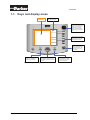
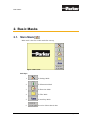
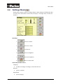
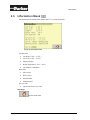
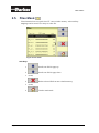
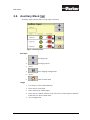
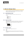
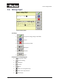
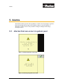
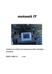
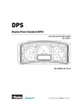
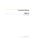
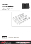
ISOBUS VT
ISOBUS Virtual Terminal
User Manual
HY33-4010-IB/UK
Vansco Electronics Oy (Parker Hannifin Corporation)
Electronic Controls Division
PO Box 86 (Tiilenlyöjänkatu 5)
FI-30101 Forssa, Finland
Office +358 3 412 4400
Fax
+358 3 433 5157
http://www.parker.com/ecd
[email protected]
Copyright 2009 © Parker® Hannifin Corporation. All rights reserved. No part of this work may
be reproduced, published, or distributed in any form or by any means (electronically,
mechanically, photocopying, recording, or otherwise), or stored in a database retrieval system,
without the prior written permission of Parker Hannifin in each instance.
WARNING!
FAILURE OR IMPROPER SELECTION OR IMPROPER USE OF THE PRODUCTS AND/OR
SYSTEMS DESCRIBED HEREIN OR RELATED ITEMS CAN CAUSE DEATH, PERSONAL
INJURY AND PROPERTY DAMAGE.
This document and other information from Parker Hannifin Corporation, its subsidiaries and
authorized distributors provide product and/or system options for further investigation by users
having technical expertise. It is important that you analyze all aspects of your application and
review the information concerning the product or system in the current product catalog. Due to the
variety of operating conditions and applications for these products or systems, the user, through
its own analysis and testing, is solely responsible for making the final selection of the products
and systems and assuring that all performance, safety and warning requirements of the
application are met.
The products described herein, including without limitation, product features, specifications,
designs, availability and pricing, are subject to change by Parker Hannifin Corporation and its
subsidiaries at any time without notice.
Offer of Sale
The items described in this document are hereby offered for sale by Parker Hannifin Corporation,
its subsidiaries or its authorized distributors. This offer and its acceptance are governed by the
provisions stated in the "Offer of Sale" elsewhere in this document, or available at
www.parker.com.
Page 2 of 21
ISOBUS VT
Table of Contents
1. Introduction
1.1.
Keys and display areas
2. Basic Masks
6
7
2.1.
Main Mask
7
2.2.
Settings Mask
8
2.3.
Information Mask
10
2.4.
DateTime Mask
11
2.5.
Files Mask
12
2.6.
Auxiliary Mask
13
3. How to change values
14
3.1.
Input Boolean field
14
3.2.
Input List field
14
3.3.
Number input
14
3.4.
3.3.1. Edit
3.3.2. Number editor
String input
14
15
16
4. Information notes
18
5. Alarms
19
5.1.
19
Alarms that can occur in system pool
6. Splash screen
6.1.
User Manual
5
Parker Splash screen
21
21
Page 3 of 21
Page 4 of 21
ISOBUS VT
Introduction
1. Introduction
A virtual terminal (VT) is an electronic control unit (ECU), consisting of a graphical
display, connected to an ISO 11783 network that provides the capability for an ECU
implement to interact with operator. When Working Set (WS) detects the VT in
ISOBUS network, it can send an ObjectPool1 to the VT or download the saved pool
from VT’s non-volatile memory. If the WS is active on the VT screen, all soft key
and editing button presses are sent to the WS. The WS can modify its own pool at the
VT at any time.
Parker’s ISOBUS-VT is designed for vehicle use only, and indoor use with high
temperature range. Certification of the Parker’s ISOBUS-VT guarantees that it is
compliant with other ISOBUS products on the market.
1
ObjectPool is a group of objects that describes user interface seen on the VT screen.
User Manual
Page 5 of 21
Introduction
1.1. Keys and display areas
Data Mask area
Soft Key Designator
Rotary encoder is used to
move between different input
fields on the screen and
change values of these
fields. This has also push
button which acts as Enter
key
Softkeys ase used to select
the virtual key on the right
hand side of the screen
Change working set key is
used to change between
active implements on the
screen and to go to VT’s
home screen.
ESC key is used to cancel
operation in input fields so
the value is not changed
This four directional button can be
used instead of rotary encoder to
move between different input fields
on screen
ACK key is used
acknowledge alarm display
in case there is no softkey
on alarm mask page
Figure 1: Keys and display areas
Page 6 of 21
ISOBUS VT
Basic Masks
2. Basic Masks
2.1. Main Mask
Main mask is the first visible mask after start up.
Figure 2: Main mask
Soft Keys
User Manual
1.
To Settings Mask
2.
To Information Mask
3.
To Date time Mask
4.
To Files Mask
5.
To Auxiliary Mask
6.
No action. Shows date & time
Page 7 of 21
Basic Masks
2.2. Settings Mask
Setting mask contains controls to change display, audio settings and information that
are sent to ECU (Electronic Control Unit) on request. To change values on mask see
section 3.
Figure 3: Main mask
Soft Keys
1.
Increase volume
2.
Decrease volume
3.
Volume test
4.
Increase brightness
5.
Decrease brightness
6.
Back to main mask
Units with possible values
Language
•
en (this list changes according to connected devices)
Decimal
•
(point or comma)
Night Mode
•
Page 8 of 21
(inverts display)
ISOBUS VT
Basic Masks
Distance
•
Metric
•
Imperial
Area
•
Metric
•
Imperial
Volume
•
Metric
•
Imperial
•
US
Mass
•
Metric
•
Imperial
•
Tons/pounds
Temperature
•
Metric
•
Imperial
Pressure
•
Metric
•
Imperial
Force
•
Metric
•
Imperial
System
User Manual
•
Metric
•
Imperial
•
US
Page 9 of 21
Basic Masks
2.3. Information Mask
Information mask contains information about VT (Virtual Terminal).
Figure 4: Information mask
Variable data
•
Can High (2.25V – 2.75V )
•
Can Low (2.25V – 2.75V )
•
Supply Voltage
•
Board temperature (-30°C - 80°C)
•
Can address (38 default)
Static data
•
SW-version
•
HW-version
•
Serial number
•
Manufactured
Service code
•
(input field for service code)
Soft Keys
Back to main mask
Page 10 of 21
ISOBUS VT
Basic Masks
2.4. DateTime Mask
DateTime has input fields to change date, time and time format.
Figure 5: DateTime
Date
•
Number input fields for date according to Format
Format
•
DD:MM:YYYY (day:month:year)
•
DD:YYYY:MM
•
MM:YYYY:DD
•
MM:DD:YYYY
•
YYYY:MM:DD
•
YYYY:DD:MM
Time
•
<Hour>:<Minute>
12 Hour
Soft Keys
Back to main mask
User Manual
Page 11 of 21
Basic Masks
2.5. Files Mask
Virtual terminal can save pools into VT’s non-volatile memory. Also auxiliary
mappings can be stored. Use rotary to select file.
Figure 6: Files mask
Soft Keys
1.
Scrolls one file list page up
2.
Scrolls one file list page down
3. (none)
4.
Delete selected file from non volatile memory.
5. (none)
6.
Page 12 of 21
Back to main mask
ISOBUS VT
Basic Masks
2.6. Auxiliary Mask
Auxiliary mask contains editor to map input to function
Figure 7: Auxiliary mask
Soft Keys
1.
Scroll page up
2.
Scroll page down
3. (none)
4.
Save mapping configuration.
5. (none)
6.
Back to main mask
Usage
1. Use rotary to select wanted function
2. Press enter to focus input
3. Select with rotary wanted input.
4. Press enter to validate selection. Now VT tries to connect input to function.
If this fails VT shows alarm mask.
5. Save configuration
User Manual
Page 13 of 21
How to change values
3. How to change values
ISO 11783-6 standard has four different kind of input fields for user. Field types are
Boolean, List, Number, String. These fields can be selected with rotary if they are
enabled. ESC key aborts editing at any time.
3.1. Input Boolean field
This field has been implemented as square box. Enter key chances value.
Examples:
•
Enabled, false
•
Enabled, true
•
Disabled, true
3.2. Input List field
Input list field is invisible container that can contain objects. To change value of the
input list field object, press enter when the object is selected. Now the object is
framed. Use rotary to change new value. Press enter to accept new value.
Examples:
•
Selected
•
Active
•
Disabled
3.3. Number input
There are two ways to change number input values.
3.3.1.
Edit
Press enter when the object is selected. The object will become framed and active.
Use rotary to increase or decrease the value. You can use also +/- keys. Press enter to
accept value.
Page 14 of 21
ISOBUS VT
How to change values
Examples:
3.3.2.
•
Active
•
Disabled
Number editor
When you double click with enter key selected number input field, the VT opens
number editor mask.
Figure 8: Number editor mask
Soft Keys
1.
Accept new value
2.
Cancel
Mask Objects
•
Min (Displays minimum possible input value).
•
Max (Displays maximum possible input value).
•
OK (Accept value)
•
ESC (Cancel)
•
< (Editor cursor step backward)
•
> (Editor cursor step forward)
•
1-9 and ± (Editor keyboard)
Usage
Use editor keyboard with rotary and enter to input value. If value is invalid VT will
show alarm mask.
User Manual
Page 15 of 21
How to change values
3.4. String input
Figure 9: String editor
Soft Keys
1.
Accept new string (string in edit field)
2.
Cancel
3.
Clear edit text field
4.
Backspace
5.
Newline
6.
Space
Edit buttons in string keyboard
Page 16 of 21
•
Accept new value
•
Cancel editing
•
Backspace
•
New line
•
Space
•
Editor cursor step backward
•
Editor cursor step forward
•
Line step up
ISOBUS VT
How to change values
•
Line step down
Usage
Use editor keyboard with rotary and enter to input value.
User Manual
Page 17 of 21
Information notes
4. Information notes
VT informs user with message boxes. The box is seen the lower left of the screen
certain time even mask or working set is changed.
Figure 10: Message box
Page 18 of 21
ISOBUS VT
Alarms
5. Alarms
Alarm Mask informs operator about problems or failures in the workingset. Operator
must acknowledge this message with available softkeys or by ACK button. If
Alarmask is on the screen it is not possible to change workingset with change
workingset button.
5.1. Alarms that can occur in system pool
Figure 11: Board temperature alarm mask
Figure 12: Auxiliary assignment error mask
User Manual
Page 19 of 21
Alarms
Figure 13: Number Edit error mask
Page 20 of 21
ISOBUS VT
Splash screen
6. Splash screen
6.1. Parker Splash screen
Splash screen is the first visible picture after start up, and is shown for 3 seconds.
Figure 14: Splash screen
User Manual
Page 21 of 21