1
~
soarkfun,
'ELECTRONICS
Thermo-control Anti-Static
User's Manual
wm
.
l
In this instruction manual, "WARNING"
and" CAUTION" are defined asfollows.
CAUTION!
•
•
•
Do not modify the unit.
Use only genuine replacement parts.
Do not wet the unit or use the unit when
your hands are wet.
• The soldering process will produce smoke,
so make sure the area is well ventilated.
• While using the unit, don't do anything
that may cause bodily harm or physical
damage.
WARNING!
TheATTEN 90 7 Must be
UseATTEN Heating Element.
WARNING:
It should be maintained by qualified
electric technician or service personnel
specified by original factory.
When the power is on, the tip temperature is
between 200'C/392'F and 480"C1896 ·F.
CAUTION: Misuse may potentially
cause injury to the user or physical
damage to the objects involved.For your
own safety, be sure to comply with these
Precautions ..
~"",~,£2iJ
Since mishandling may lead to
burns or fire, be sure to comply
with the following precautions.
•
•
Do not tou eh the metallic parts near the tip.
Do not use the product near flammable
items.
• Advise other people in the work area: the
unit can reach a very high temperatnre and
should be considered potentially dangerous.
• Turn the power off while taking breaks and
when finished using the unit.
• Before replacing parts or storing the unit,
turn the power off and allow the unit to cool
down to room temperatnre.
To prevent damage to the unit and
ensure a safe working
environment, be sure to comply
with the following precautions.
•
Do not use the unit for applications other
than soldering.
• Do not rap the soldering iron against the
workbench to shake off residual solder, or
otherwise subject the iron to severe shocks.
Please check the contents of the
package and confirm that all the
items listed below are included.
Station
Ipe
Soldering Iron
Iron Holder (With Cleaning Sponge)
Ipc
Instruction Manual
Ipc
Power Voltage
Power Consumption
Temperature Range
Tip Leakage Voltage
Standard Tip
1 set
AC 220V 50Hz
(AC llOV 60Hz Optional)
60W(max)
220--480 'C
<O.SmV
900M
Setting up & Operating
the Unit
CAUTION!
The sponge is compressed. It will swell=--when moistened with water. Before using
the unit, dampen the sponge with the
water and squeezed it dry. Failure to do
may result in damage to the soldering
tip.
S?
t,
CAUTION: - DOII't overtighten the
knob lock. - DOII't attempt to turn the
knob when the knob lock is 011.
4. Turn on the Power Switch.
The heater lamp blinks on and off when the tip
temperature reaches the set temperature. The
unit is now ready to perform soldering work.
CAUTION: The soldering iron must be
placed
ill
the iron holder when not in use.
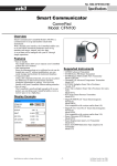
1. Iron Holder
•
Small Cleaning Sponge. Dampen the small
cleaning sponge with water and then
squeeze it dry. Place it in one of the 4
openings of the iron holder base.
• Add water to approximately the level as
shown. The small sponge will absorb water
to keep the larger sponge above it wet at all
times. The large sponge may be used alone
(wlo small sponge & water).
• Dampen the large cleaning sponge and
place it on the iron holder base.
CAUTION: Be
to turn off the
power switch before connection or
disconnecting the soldering iron. Failure
to do so may damage the P. C. B.
2. Connections
•
•
•
Connect the cord assembly to the receptacle.
Place the soldering iron in the iron holder.
Plug the power cord into the power supply.
Be sure to ground the unit.
3. Set the Temperature
•
Set the temperature control knob to the
desired temperature.
• Lock the knob. The sparkfun937 station is
equipped with a temperature control knob
l?ck. After setting the desired temperature,
tighten the hex nut on the underside ofthe
knob mount using the supplied hex wrench.
TU11lthe nut clockwise to tighten the knob
lock.
1. Tip Temperature
High soldering temperatures can degrade the
hp.
Use the lowest possible soldering
temperature: The excellent thermal recovery
characteristics ensure efficient and effective
soldering even at low temperatures.
2. Cleaning
Clean the tip regularly with a cleaning sponge,
as oxides and carbides from the solder and flux
can form impurities on the tip.
These impurities can result in defective joints
or reduce the tip's heat conductivity.
When using the soldering iron continuously, be
sure to loosen the tip and remove all oxides at
least once a week.
This helps prevent seizure and reduction of the
tip temperature.
3. When Not in Use
Never leave the soldering iron sitting at high
temperature for long periods of time as the
tip's solder plating will become covered with
oxide, which can greatly reduce the tip's heat
conductivity.
4. After Use
Wipe the tip clean and coat the tip with fresh
solder. This helps prevent tip oxidation.
h
Shape of the tip. The preferred method of
adjustment uses a tip thermometer (See
"Calibrating the Iron Temperature").
1. Inspect and Clean the Tip
CAUTION: Never file the Tip to remove
oxide.
WARNING!
•
•
Set the temperature to 250'C(482"F).
When the temperature stabilizes, clean the
tip with the cleaning sponge and check the
condition of the tip.
• If there is black oxide on the solder-plated
portion of the tip, apply new solder
(containing flux) and wipe the tip on the
cleaning sponge.
Repeat until the oxide is completely
removed. Coat with new solder.
• If the tip is deformed or heavily eroded,
replace it with a new one.
2. Calibrating
Disconnect the power plug before
servicing. Failure to do so may result
electric shock.
ill
If the power cord is damaged, it must be
replaced by the manufacturer, its service
agent or similarity qualified person in
order to avoid personal injury or damage
to the unit.
Problem 1.
The heater lamp does not light up.
the Iron Temperature
The soldering iron should be recalibrated
after changing the iron, or replacing the
heating element or tip.
• Connect the cord assembly plug to the
receptacle on the station.
• Set the temperature control knob to 400'C
(750·F).
.
• Turn the power switch to "ON" and wait
until the temperature stabilizes. Remove the
CAL pot plug.
• When the temperature stabilizes, use a
straightedge ( -) screwdriver or small plus
(+) screwdriver to adjust the screw
(marked CAL at the station) Until the tip
thermometer indicates a temperature of
400·C(750·F). Turn the screw clockwise to
increase the temperature and
counterclockwise to reduce the temperature.
Replace the CAL pot plug.
[Check 1.]
Is the power cord and/or connecting plug
disconnected?
• Connect it.
[Check 2.]
Is the fuse blown?
. .
• Determine why the fuse blew and eliminate
the cause, then replace the fuse.
a. 1~
the inside of the iron short-circuited?
b. Is the grounding spring touching the
heating element?
c. Is the heating element lead twisted and
short-circuited?
Problem 2.
The heater lamp lights up but the tip
does not heat up.
[Check 3.]
Is the soldering iron cord broken?
• Refer to "Checking for breakage in the cord
assembly."
[Check 4.]
Is the Heating Element broken?
• Refer to "Checking for breakage in the
heating element."
3. Tips
The tip temperature will vary according to the
o
Problem 3.
The tip heats up intermittently.
[Check 3.]
Problem 4.
The tip is not wet.
[Check 5.]
Is the tip temperature too high?
• Set an appropriate temperature.
[Check 6.]
Is the tip clean?
• Refer to 'Tip Care and Use '.
Problem 5.
The tip is not wet.
[Check 7.]
Is the tip coated with oxide?
• Refer to "Insect and clean the tip" .
[Check 8.]
Is the iron calibrated correctly?
• Recalibrate.
Problem 6.
The tip cannot be pulled off.
[Check 9.]
Is the tip seized?
Is the tip swollen because of deterioration?
• Replace the tip and the heating element.
Problem 7.
The tip doesn't hold the desired
temperature
[Check 8.]
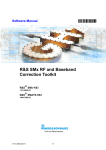
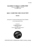
Interchangeable
900M-T-O.8D
-::
0) ~~F=c::C11
DC
I
~'O.024'
900M-T-1.2D
'7(O.68~+--·
J
----
o i~F=cr::::j+----_J
cc
Imo.smJ
t?tO.02B)
~~t:::~
e.~.
O'C
t'(OO>6)
900M-T-2.4D
{O.l)
@~~~~
~
(02)
-
O §";)I=
20
_
0~~~=======:111-----_
t7(0028)
cc
900M-I·RT
O~~I=~
1-----
4'
~(OOOB)
® ~~I=.~i---_J
~
8~~1=
900M tip OutDiam
<l> 6.5
0) ~<:n
~JI-----
-10'CJ-18°F
®l I<;:~~
"
900M·T-3C
900M-T-3CF@l
0.06)
900M-T·SI
~I-----
0'(;
~2
ci~
]
O'C
900M-T-1
0<;
900M-T-2C
900M-T-2CF
900M-T-H
19(0.74)
900M-T-1.8H,!}
~'!O'04)
'''ro,0>;
~';lt=~i------
/o~
-20'C I-36°F
~~t:E3
900M-T-S4
e.o
I-----~
170.66
t------J
.,;})/i29;2~~
-20'C I-36°F
~
J
.:,.I:J~~1.2(O'04)
1-----
17(0.66)
5'
o
~
OC:
O ~;;I= ~~f-----
0'C
900M·j·4C
900M.T-4CF@l
0'C
~ ~~tc~=s
J
17(0.66'
0<;
~
]
1-----
15(G.6
~f-----
·1 O'C I-18°F
900M·T·1C
900M.T-1C
f-----
~
@~~ca
+30'C!+54°F ~.oa)
900M-T-R
~
O'C
900M·T·1.5CF
(025)
f"s1O.02\
0'C
900M-T-B
f-----
900M-T-K
45"
-10'C/-18°F
900M-T-O.SC
_
~
~~~r=~
~
1-
~
O·C
t,(o.OO)
900M-T-3.2D
-lOO-18°F
900M-T-SB
_
900M-T-0.8C
~
~
900M-T-1.2D
O~2~+-
900M-T-LB
0"(;
900M-T-1.6D
O'C
Soldering Tips of Soldering Station
o'c
5<>
'--
_
l
1410.55)
:g
~S(C01)
0) e.~~
EEI----J