1
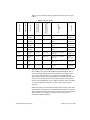
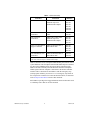
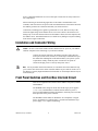
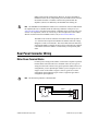
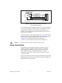
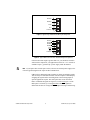
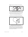
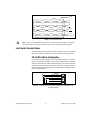
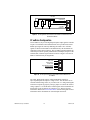
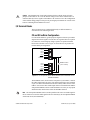
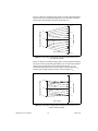
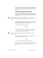
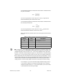
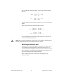
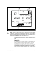
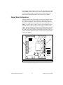
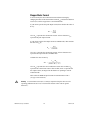
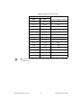
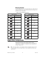
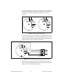
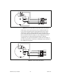
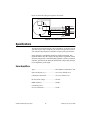
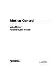
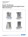
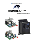
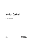
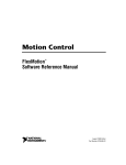
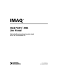
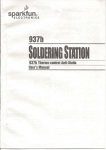
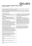
USER GUIDE
NUDRIVE
ACCESSORY
This user guide describes the electrical and mechanical aspects of the
nuDrive power amplifier accessory and describes how to use the nuDrive
with your motion controller.
Contents
Conventions ............................................................................................ 2
Introduction ............................................................................................. 2
What You Need to Get Started ............................................................... 5
Safety Information .................................................................................. 5
Installation and Connector Wiring.......................................................... 6
Front Panel Switches and Host Bus Interlock Circuit............................. 6
Rear Panel Connector Wiring ................................................................. 7
Motor Power Terminal Blocks ........................................................ 7
Encoder Terminal Blocks ................................................................ 8
Limit Switch Terminal Blocks......................................................... 11
CX and SX nuDrive Configuration .......................................... 11
CF nuDrive Configuration........................................................ 12
I/O Terminal Blocks ........................................................................ 13
CX and SX nuDrive Configuration .......................................... 13
CF nuDrive Configuration........................................................ 15
Amplifier/Driver Command Signals....................................................... 16
Servo Amplifier Signals................................................................... 16
Stepper Driver Signals ..................................................................... 16
Optional Configurations.......................................................................... 16
E-Stop Terminal Block .................................................................... 16
Servo Amplifier Configurations ...................................................... 17
Adjusting Current Gain and Current Limits ............................. 19
Balancing the Amplifier Gain................................................... 21
Status LEDs .............................................................................. 22
Stepper Driver Configurations......................................................... 23
Stepper Motor Current.............................................................. 24
Microstep Selection .................................................................. 26
Stepper Motor Configurations ................................................................ 26
Specifications .......................................................................................... 29
FlexMotion™, National Instruments™, ni.com™, nuDrive™, and ValueMotion™ are trademarks of National Instruments Corporation. Product and
company names mentioned herein are trademarks or trade names of their respective companies.
321942B-01
© Copyright 1998, 2000 National Instruments Corp. All rights reserved.
January 2000
Conventions
The following conventions are used in this manual:
This icon denotes a note, which alerts you to important information.
This icon denotes a caution, which advises you of precautions to take to
avoid injury, data loss, or a system crash.
This icon denotes a warning, which advises you of precautions to take to
avoid being electrically shocked.
♦
The ♦ symbol indicates that the following text applies only to a specific
product.
overline
Indicates the signal is active-low.
italic
Italic text denotes emphasis, a cross reference, or an introduction to a key
concept. This font also denotes text that is a placeholder for a word or value
that you must supply.
CF nuDrive
Refers to the 4CF-001 and 2CF-001 nuDrives.
CX nuDrive
Refers to the 4CX-001 and 2CX-001 nuDrives.
SX nuDrive
Refers to the 4SX-211, 2SX-211, 4SX-411, and 2SX-411 nuDrives.
stepper nuDrive
Refers to the 4SX-211, 2SX-211, 4SX-411, and 2SX-411 nuDrives.
servo nuDrive
Refers to the 4CF-001, 2CF-001, 4CX-001, and 2CX-001 nuDrives.
Introduction
Your nuDrive accessory is a complete power amplifier and system
interface for use with up to four axes of simultaneous or independent servo
or stepper motion control. Ideally suited to industrial and laboratory
applications, your nuDrive has everything you need to connect motors,
encoders, limit switches, I/O, and other motion hardware to National
Instruments motion controllers.
nuDrive Accessory User Guide
2
www.ni.com
Table 1 lists the available nuDrives and describes the properties of each
nuDrive.
AC Input
Driver/Amplifier
Type
Driver/Amplifier
Nominal Bus Voltage
Motion Board
Cable Connector
Motor Type
Number of Axes
nuDrive Type
Table 1. nuDrive Properties
4SX-411
4
Stepper
(2-phase)
50-pin
40 VDC Bus
Microstepping Driver
IM483
115 V
(50/60 Hz)
2SX-411
2
Stepper
(2-phase)
50-pin
40 VDC Bus
Microstepping Driver
IM483
115 V
(50/60 Hz)
4SX-211
4
Stepper
(2-phase)
50-pin
24 VDC Bus
Microstepping Driver
IM483
115 V
(50/60 Hz)
2SX-211
2
Stepper
(2-phase)
50-pin
24 VDC Bus
Microstepping Driver
IM483
115 V
(50/60 Hz)
4CX-001
4
DC Brush
Servo
50-pin
48 VDC Bus
DC Brush Servo Amplifier
SSA 8/100
115 V
(50/60 Hz)
2CX-001
2
DC Brush
Servo
50-pin
48 VDC Bus
DC Brush Servo Amplifier
SSA 8/100
115 V
(50/60 Hz)
4CF-001
4
DC Brush
Servo
100-pin
48 VDC Bus
DC Brush Servo Amplifier
SSA 8/100
115 V
(50/60 Hz)
2CF-001
2
DC Brush
Servo
100-pin
48 VDC Bus
DC Brush Servo Amplifier S
SA 8/100
115 V
(50/60 Hz)
The nuDrive can drive a broad range of servo or stepper motors.
Servo nuDrives use pulse-width modulation (PWM) amplifiers with a
user-specified peak output current rating and a DC bus voltage to drive
servo motors. Stepper nuDrives use a rugged microstepping bipolar
chopper driver. Stepper driver configurations are available in a wide range
of user-specified current per phase and voltage settings to drive stepper
motors. In all configurations, power supplies are built in and use standard
115 VAC for operation. Electronics are fan cooled to assure reliable
operation.
nuDrives simplify your field wiring through separate encoder, limit switch,
and motor power removable screw terminal connector blocks for each axis.
The terminal blocks do not require any special wiring tools for installation.
Refer to Table 2 for a summary of how to connect various motion
controllers to different nuDrives.
© National Instruments Corporation
3
nuDrive Accessory User Guide
Table 2. nuDrive Connectivity
Controller
Connection
nuDrives
All 7344 controllers
SH68-C68-S cable with a
68M-50F step/servo
bulkhead cable adapter
4SX-411
2SX-411
4SX-211
2SX-211
4CX-001
2CX-001
All FlexMotion-6C
controllers
SH100-100-F shielded cable
cable
4CF-001
2CF-001
All 7324/7314
controllers*
SH68-C68-S cable with a
68M-50F step/servo
bulkhead cable adapter
4SX-411
2SX-411
4SX-211
2SX-211
Non-73xx ValueMotion
stepper controllers
SH50-50 shielded cable or
NB1 ribbon cable
4SX-411
2SX-411
4SX-211
2SX-211
All ValueMotion servo
controllers
SH50-50 shielded cable or
NB1 ribbon cable
4CX-001
2CX-001
*For PXI-7324/7314 controllers prior to Rev. C, make the connection using a SH68-68-S
cable with a 68M-50F step/servo bulkhead cable adapter.
nuDrives have three levels of amplifier inhibit/disable protection for motion
system shut down. The front panel contains both enable and power switches
for direct motor inhibiting and system power-down operations. Each
nuDrive also has a host bus power interlock that activates an amplifier
inhibit signal if the host computer is shut down or the motion controller
interface cable is disconnected. On nuDrives with the emergency stop
(E-Stop) option enabled, you can wire a 115 V emergency stop switch to
the rear panel I/O connector for remote interlock shut down, as described
in the E-Stop Terminal Block section of this document.
Each nuDrive is packaged in a rugged aluminum enclosure that can be used
as a benchtop unit or that can be rack-mounted.
nuDrive Accessory User Guide
4
www.ni.com
What You Need to Get Started
To set up and use your nuDrive accessory, you will need the following
items:
❑ The nuDrive accessory and nuDrive Accessory User Guide
❑ Power cord (IEC type)
❑ One or more of the following National Instruments cables and
adapters:
–
SH68-68-S shielded cable, part number 185262-02
–
NB1 ribbon cable, part number 180524-20
–
SH50-50 shielded cable, part number 185319-02
–
SH100-100-F shielded cable, part number 185095-02
–
SH68-C68-S shielded cable, part number 186381-02
–
68M-50F step/servo bulkhead cable adapter, part number
185630-01
❑ (Optional) ISO power supply (for FlexMotion-6C boards)
Detailed specifications for the nuDrive accessory are in the Specifications
section later in this guide.
Safety Information
Warnings Keep away from live circuits. Do not remove equipment covers or shields unless
you are trained to do so. Hazardous voltages may exist even when the equipment is turned
off. To avoid a shock hazard, do not perform procedures involving cover or shield removal
unless you are qualified to do so and disconnect all field power prior to removing covers or
shields.
Do not operate damaged equipment. The safety protection features built into this device
can become impaired if the device becomes damaged in any way. If the device is damaged,
turn the device off and do not use until service-trained personnel can check its safety. If
necessary, return the device to National Instruments for service and repair to ensure that its
safety is not compromised.
Do not operate this equipment in a manner that contradicts the information specified in this
document. Misuse of this equipment could result in a shock hazard.
Do not substitute parts or modify equipment. Because of the danger of introducing
additional hazards, do not install unauthorized parts or modify the device. Return the
© National Instruments Corporation
5
nuDrive Accessory User Guide
device to National Instruments for service and repair to ensure that its safety features are
not compromised.
When connecting or disconnecting signal lines to the nuDrive terminal block screw
terminals, make sure the lines are powered off. Potential differences between the lines and
the nuDrive ground create a shock hazard while you connect the lines.
Connections, including power signals to ground and vice versa, that exceed any of the
maximum signal ratings on the nuDrive device can create a shock or fire hazard or can
damage any or all of the boards connected to the nuDrive chassis, the host computer, and
the nuDrive device. National Instruments is not liable for any damages or injuries resulting
from incorrect signal connections.
Installation and Connector Wiring
Be sure to turn off the enable switches and the main AC power to your nuDrive
and host computer before connecting to your motion controller.
Caution
Connect the motion controller to the nuDrive interface cable. Wire the
motor power, limit switch, encoder, I/O, and E-Stop terminal blocks as per
the instructions and diagrams in this manual and/or your specific system
requirements. Finally, install the power cord into the rear panel AC
connector and plug it into a correctly rated power source.
Note For 50-pin ribbon cable interconnection, be certain that the colored indicator strip
(pin 1) on the cable between the motion controller and the 50-pin connector on the rear of
the nuDrive is properly aligned and inserted on both ends. 68- and 100-pin cables are keyed
metal-shell style.
Front Panel Switches and Host Bus Interlock Circuit
There are two lighted rocker switches on the nuDrive front panel, POWER
and ENABLE.
The POWER switch energizes the DC bus and the logic power supplies
(+5 V, +12 V), and illuminates to indicate that the main AC power is
present. If the POWER switch fails to illuminate, check the power cord and
main input fuse in the power connector.
The ENABLE switch enables or inhibits the servo amplifiers or stepper
drivers. It illuminates to indicate that it is switched on and that the logic
power supply +12 V output is functioning.
nuDrive Accessory User Guide
6
www.ni.com
Either switch can turn off the motors. However, as long as the nuDrive
POWER switch is still on, independent power and enable circuits cause the
incremental encoders to continue to track motor position while the
amplifiers (drivers) are disabled by the ENABLE switch being off.
Note The ENABLE switch illuminates whenever it is switched on. It does not indicate that
the amplifiers/drivers are disabled under the following conditions: E-Stop active (see
E-Stop Terminal Block), host bus interlock fault, or amplifier/driver protection fault (over
current, over temperature, and so on). Conversely, it does not light if the remote enable
function is used because the ENABLE switch is off (see I/O Terminal Blocks).
The nuDrive has a host bus interlock circuit that monitors the presence of
+5 V from the host computer and disables the nuDrive when the voltage
disappears or falls out of tolerance. This circuit shuts down the motors by
activating the Inhibit, or disable circuit for all axes, when the host computer
is disconnected from the nuDrive or inadvertently or unexpectedly shut
down.
Rear Panel Connector Wiring
Motor Power Terminal Blocks
For motor power wiring on the nuDrive, each axis has a separate 5-position
terminal block with removable screw terminals. There are two types of
wiring from the same connector for typical operation. Which of these two
configurations you use depends upon whether you are using the servo or
stepper version of the nuDrive. Figure 1 shows a typical servo motor
configuration pin assignment. Figure 2 shows a typical stepper motor
configuration pin assignment.
Note The dotted loop indicates a shielded cable.
+
Motor +
Motor –
Motor Case Ground
–
Shield
Servo Motor
1
2
3
4
5
Figure 1. Typical Servo Motor (DC Brush Type) Terminal Block Pin Assignment
© National Instruments Corporation
7
nuDrive Accessory User Guide
Winding A Start
Winding A End
Motor Case Ground
Winding B Start
Winding B End
Stepper Motor
1
2
3
4
5
Shield
Figure 2. Typical Full-Coil Stepper Motor (2-Phase Type)
Terminal Block Pin Assignment
It is recommended you use shielded, 20 AWG wire or larger for the motor
power cable. If available, you should connect a case ground wire to pin 3
(Ground/Shield); this helps to avoid ground loops and signal noise
problems. (Case ground connects to the motor housing, and not to any of
the motor power terminals.)
The stepper nuDrives contain bipolar chopper drivers. The stepper motors
must be wired in a four-wire configuration as shown in Figure 2. Unused
lead wires must be isolated and not connected. See Stepper Motor
Configurations for additional information on connecting
6- and 8-wire motors and on the alternate half-coil configuration.
Caution
Never connect unused center taps or winding terminals to pin 3.
Encoder Terminal Blocks
For quadrature incremental encoder signals, each nuDrive axis has a
separate 8-position terminal block with removable screw terminals.
Where applicable, the nuDrive accepts two types of encoder signal
inputs: single-ended (TTL) or differential line driver. You can
accommodate open-collector output encoders by using 2.2 kΩ pullup
resistors to +5 VDC.
Figure 3 shows the typical encoder wiring pin assignment for single-ended
signal input. Figure 4 shows the typical encoder wiring pin assignment for
differential line driver signal inputs.
nuDrive Accessory User Guide
8
www.ni.com
Phase A
Phase B
Index
+5 V
Common
1
2
3
4
5
6
7
8
Figure 3. Typical Single-Ended Encoder Wiring Pin Assignment
Phase A
Phase A
Phase B
Phase B
Index
Index
+5 V
Common
1
2
3
4
5
6
7
8
Figure 4. Typical Differential Line Driver Encoder Wiring Pin Assignment
If the encoder cable length is greater than 15 ft, you should use encoders
with line driver outputs for your applications. Power for a +5 V encoder is
available on pin 7, generated by a power supply inside the nuDrive.
Note If you require other encoder power values, reference an external power supply to the
Common (ground) signal on the 8-pin encoder terminal block.
nuDrives have differential inputs for Phase A, Phase B, and Index signals.
You can easily accommodate encoders with various phase relationships by
swapping the signals and/or connecting them to the inverting inputs as
specific applications require. The index pulse must occur when both
Phase A and Phase B signals are logic low, as shown in Figure 5. If the
Index pulse is inverted, try reversing the Index and Index signals on
differential encoders or wiring to the Index input with single-ended wiring.
© National Instruments Corporation
9
nuDrive Accessory User Guide
Figure 5 shows the proper encoder phasing for CW (forward) motor
rotation.
Phase A
Phase B
Index
Figure 5. Encoder Signal Phasing, CW Rotation
Servo and closed-loop stepper applications require consistent directional
polarity between the motor and encoder for stable operation. The National
Instruments motion control standard directional polarity is as follows:
•
Positive = forward = clockwise (CW) facing motor shaft
•
Negative = reverse = counter-clockwise (CCW) facing motor shaft
Figure 6 shows the clockwise and counter-clockwise motor rotation.
W
C
W
C
C
Figure 6. Clockwise and Counter-Clockwise Motor Rotation
When connecting the encoder wiring to your nuDrive accessory, you
should use shielded wire of at least 24 AWG. Both analog and digital noise
filters filter the encoder inputs in the nuDrive and on the motion controller
itself. You must use cables with twisted pairs and an overall shield for
improved noise immunity and enhanced encoder signal integrity. Figure 7
shows twisted pairs in a shielded cable.
nuDrive Accessory User Guide
10
www.ni.com
Drain
Shield
A
A
B
B
Index
Index
+5 V
Common
Figure 7. Shielded Twisted Pairs
Note If you use an unshielded cable, noise can corrupt the encoder signals, resulting in
lost counts, reduced accuracy, and other erroneous encoder and controller operation.
Limit Switch Terminal Blocks
The limit and home switch connections for the nuDrive axes are configured
differently on different nuDrives, as described in the following sections.
CX and SX nuDrive Configuration
For end-of-travel limit and home switch connections, nuDrive axes have a
separate, six-position removable screw terminal connector block. All limit
signals are filtered in the nuDrive and debounced by the motion controller
to reduce noise sensitivity. Refer to Figures 8 and 9 for examples of passive
and active limit switch wiring using the terminal block pin assignments on
the CX and SX nuDrives.
CW Limit
Home Switch
CCW Limit
+12 VDC
+5 VDC
Common
1
2
3
4
5
6
Figure 8. Pin Assignment for the Passive Limit Switch Terminal Block on the
CX and SX nuDrives
© National Instruments Corporation
11
nuDrive Accessory User Guide
+12 VDC
+12
+12
+12
Out
Out
Out
GND
GND
GND
CW Limit
Home Switch
CCW Limit
+5 VDC
Common
1
2
3
4
5
6
Figure 9. Pin Assignment for the Active Limit Switch Terminal Block on the
CX and SX nuDrives
CF nuDrive Configuration
On CF nuDrives, the per-axis High-Speed Capture input signal is available
on pin 4 of each limit switch terminal block. Pin 5 provides an External
Inhibit input signal for remotely inhibiting the nuDrive axis. All limit
signals are filtered in the nuDrive and debounced by the FlexMotion-6C
controller to reduce noise sensitivity. The CF nuDrives and FlexMotion-6C
controllers provide for optically isolated limit switch inputs, and pin 6 is the
isolated (ISO) Common signal connection. Refer to Figure 10 for the CF
nuDrive terminal block pin assignments.
CW Limit
Home Switch
CCW Limit
High-Speed Capture
External Inhibit
ISO Common
1
2
3
4
5
6
Figure 10. Pin Assignment for the Limit Switch Terminal Block on the
CF nuDrive
The Limit, High-Speed Capture, and External Inhibit signals are
opto-coupled inputs and require a voltage source. You can either use an
external isolated voltage source, or you can use the +5 V and ground signals
on the host computer by properly setting a jumper to connect the isolated
voltage (input) to 5 V and the ISO Common signal on the FlexMotion-6C
board. Refer to the FlexMotion-6C Hardware User Manual for more
information. Refer to the I/O Terminal Blocks section of this guide for more
information on the FlexMotion-6C isolated input connection.
nuDrive Accessory User Guide
12
www.ni.com
The FlexMotion-6C board will be damaged if the isolated voltage selection
jumpers on the board are set to use the internal voltage source and an external source is
connected directly to these signals on the nuDrive. Be careful to review the configuration
of the isolated voltage jumper section prior to powering any FlexMotion-6C circuits or the
host PC containing the FlexMotion-6C board.
Caution
I/O Terminal Blocks
The I/O connectors are configured differently on different nuDrives,
as described in the following sections.
CX and SX nuDrive Configuration
For CX and SX nuDrives, general-purpose digital I/O lines are provided to
augment the motion signals. The I/O lines are organized into two separate
I/O connectors, with each group using a separate six-position terminal
block with removable screws. Figure 11 shows the two six-position I/O
terminal block pin assignments.
I/O 1
I/O 2
I/O 3
I/O 4
Enable
Common
1
2
3
4
5
6
I/O 5
I/O 6
I/O 7
I/O 8
Enable
Common
1
2
3
4
5
6
ENABLE Switch
(ON = Closed)
Figure 11. Pin Assignments for the Two Six-Position I/O Terminal Blocks on the
CX and SX nuDrives
The ENABLE switch, located on the front panel of your nuDrive, controls
the enable signal input. The active-low enable signal input is also available
on pin 5 of each I/O terminal block and can remotely enable all axes in the
nuDrive. You can use either enable input on the I/O terminal blocks OR the
front panel ENABLE switch to enable the nuDrive accessory. E-stop inputs
and the host bus interlock also affect the ENABLE function.
Note The front panel ENABLE switch is wired in parallel to the active-low enable signal of
the I/O connector. To use the enable signal in the I/O connector(s), the front panel ENABLE
switch must be off (not illuminated).
© National Instruments Corporation
13
nuDrive Accessory User Guide
The ENABLE switch is illuminated whenever it is switched on. It will not indicate that the
amplifiers/drivers are disabled under the following conditions: E-Stop (see the E-Stop
Terminal Block section), Host Bus interlock fault, or amplifier/driver protection fault.
Conversely, it will not light if the external Enable function is used via the I/O terminal blocks.
♦
SX nuDrives
When using an SX nuDrive, I/O pins 5 through 8 reflect the status of the
driver inhibits for axes 1 through 4 respectively. Each driver inhibit status
signal is the combination of the E-stop, enable, host bus interlock, and per
axis inhibit signals.
♦
CX nuDrives
To use the amplifier inhibit functionality of the 7344 controller, set jumpers
JP2 through JP5 to the Inhibit position (recommended). When the jumpers
are set to the Inhibit position, I/O lines 5 through 8 reflect the status of the
driver inhibits for axes 1 through 4 respectively. To use I/O lines
5 through 8 as general purpose digital I/O signals (required for
ValueMotion servo controllers), set jumpers JP2 through JP5 to the
Digital I/O position.
Note Your CX nuDrive is shipped with jumpers JP2 through JP5 in the Digital I/O
position. These jumpers are located near the left edge of the interface board inside the
nuDrive, as shown in Figure 12.
1
2
3
4
1
JP2
2. JP3
3
JP4
4. JP5
Figure 12. Jumper Locations
Digital I/O
Inhibit
Figure 13. CX nuDrive Jumper Configuration
nuDrive Accessory User Guide
14
www.ni.com
CF nuDrive Configuration
There are two I/O connectors (upper and lower) on the CF nuDrive. Each
I/O connector uses a six-position removable screw terminal block. The
upper terminal block provides access to four channels of ±10 V A/D
converter analog input as well as analog reference voltage output from the
converter circuit and reference common signal connections. The lower
terminal block provides access to breakpoint output digital I/O signals as
well as an isolated external power supply voltage input connection. Refer
to Figures 14 and 15 for the upper and lower FlexMotion-compatible I/O
terminal block pin assignments.
A/D Input Channel 1
A/D Input Channel 2
A/D Input Channel 3
A/D Input Channel 4
Analog Ref. Output
Analog Common
1
2
3
4
5
6
Figure 14. Upper I/O Terminal Block Pin Assignment on the CF nuDrive
Breakpoint Output 1
Breakpoint Output 2
Breakpoint Output 3
Breakpoint Output 4
Isolated Voltage (Input)
Isolated Common
1
2
3
4
5
6
Figure 15. Lower I/O Terminal Block Pin Assignment on the CF nuDrive
The breakpoint output digital signals are opto-coupled outputs and require
an isolated voltage source connected to the isolated voltage and isolated
common inputs. You can either use an external isolated voltage source, or
you can use the +5 V and ground signals on the host computer by properly
setting a jumper to connect the isolated voltage (input) to 5 V and the ISO
Common signal on the FlexMotion-6C board. Refer to the FlexMotion-6C
Hardware User Manual for more information.
© National Instruments Corporation
15
nuDrive Accessory User Guide
Amplifier/Driver Command Signals
Servo Amplifier Signals
The servo amplifiers used in the servo versions of the nuDrive accept an
industry-standard ±10 V analog torque (current) command signal. Servo
motion controllers used with the nuDrive provide this standard output and
are programmed to close both the velocity loop and position loop using an
enhanced PID algorithm.
Stepper Driver Signals
For stepper drivers, there are two industry standards for command signals:
•
Step and Direction signals (nuDrive standard)
•
Independent CW and CCW pulses
The nuDrive uses stepper drivers that have active-low step and direction
inputs. You must configure the stepper outputs of your stepper controller
for Step and Direction signals with inverted (active-low) polarity. This
configuration is the National Instruments default output configuration for
stepper controller boards and nuDrives.
Optional Configurations
Be sure to turn off the ENABLE switch and disconnect the main AC power as
well as the E-Stop 115 VAC input from the nuDrive before opening the nuDrive cover or
accessing any components within the nuDrive.
Warning
This section describes optional configurations for your nuDrive accessory.
The nuDrive is factory configured with default settings appropriate for
many applications. If required, you can modify the parameters and settings
on the individual axis drivers to meet your specific application
requirements.
E-Stop Terminal Block
The E-Stop option has a separate three-position removable screw terminal
block on the nuDrive back panel.
Note Your nuDrive is shipped with the E-Stop disabled. To enable the E-Stop, remove the
jumper from JP1 located on the interface board inside the nuDrive. JP1 is the single two-pin
header near the E-Stop 3 position terminal block.
nuDrive Accessory User Guide
16
www.ni.com
Figure 16 shows the location of the E-Stop terminal block (and E-Stop
configuration jumper) on the interface board.
2
1
1
E-Stop
2
JP1
Figure 16. E-Stop Location
If you enable the E-Stop option, you must apply a 115 VAC signal to pins
1 and 3 in addition to the normal nuDrive enable (ENABLE switch or I/O
connector enable input, if applicable) for the nuDrive’s amplifiers/drivers
to be enabled (not inhibited). If you disconnect the 115 VAC with the
E-Stop option selected, the amplifiers/drivers are immediately disabled
(inhibited) regardless of the status of the ENABLE switch or enable input.
Refer to Figure 17 for more information on the E-Stop terminal block pin
assignment.
115 VAC (Line)
NC
115 VAC (Neutral)
1
2
3
Figure 17. E-Stop Terminal Block Pin Assignment
Note The front panel ENABLE switch will remain illuminated even when the 115 VAC
signal is removed from the E-Stop connector, disabling the axes.
Servo Amplifier Configurations
The servo nuDrive uses high-efficiency PWM amplifiers configured as
torque blocks (current amplifiers or transconductance amplifiers). The
current gain is given in amps/volt and defines the relationship of the input
command voltage to the current output. The peak current limit is the
maximum current that your motor can withstand for short periods of time.
The continuous current limit is the maximum current that your motor can
withstand indefinitely.
© National Instruments Corporation
17
nuDrive Accessory User Guide
Figure 18 shows the command voltage input to current output relationship
for periods of time less than approximately two seconds. The maximum
current output corresponds to the peak current limit, Ipeak.
+Vmax
+I cont
0A
0V
Output Current
Input Command Voltage
+I peak
–I cont
–V max
Gain Applied
–I peak
Figure 18. Input Voltage to Output Current Relationship for Periods of Time
Less Than Two Seconds
Figure 19 shows the command voltage input to current output relationship
for periods of time greater than approximately two seconds. The maximum
current output corresponds to the continuous current limit, Icont, so
command voltages that would result in a higher current output than Icont
when the gain is applied instead result in a current output of Icont.
+Vmax
+I cont
0A
0V
Output Current
Input Command Voltage
+I peak
–I cont
–V max
Gain Applied
–I peak
Figure 19. Input Voltage to Output Current Relationship for Periods of Time
Greater Than Two Seconds
nuDrive Accessory User Guide
18
www.ni.com
The amplifier peak and continuous current limits and the current gain have
been factory set for 5 A continuous and 10 A peak current output. Verify
that these settings are appropriate for your application before powering
your motors.
Adjusting Current Gain and Current Limits
You can adjust the current gain and current limits by changing the values
of R6, R7, R40, and R42 on the servo amplifiers. The resistors are standard
1/4 W axial leaded type and are plugged into sockets on the PWM per axis
servo drives.
Note Some components on your nuDrive are missing from their sockets. These
components were removed at the factory to configure the amplifier as a torque (current)
block.
Configure the current gain on the nuDrive so that the value of the maximum
command voltage, when multiplied by the gain, results in the value of the
maximum allowable peak current, as shown in Figure 18.
Calculate the gain using the following formula:
I peak
Gain = ---------V max
where Gain represents the gain value in amps/volt, Ipeak represents the
maximum allowable peak current, and Vmax represents the maximum
command voltage from your motion controller.
Note ±10 V is the maximum/minimum command voltage for National Instruments
motion controllers.
Once you have calculated your gain value, determine the resistor values for
R6 and R7 using the following formula:
50
R 6, 7 = ------------Gain
where R6,7 is the value for both resistor R6 and resistor R7 in kΩ.
After setting the gain value, you need to adjust the values of the R40 and
R42 resistors to configure your peak current limit and continuous current
limits.
© National Instruments Corporation
19
nuDrive Accessory User Guide
Use the following formula to calculate the value for R42, which determines
the peak current limit:
10 × I peak
R42 = ---------------------20 – I peak
where R42 represents the resistor value in kΩ and Ipeak represents the
maximum allowable peak current for the motor.
Use the following formula to calculate the value for R40, which determines
the continuous current limit:
2 × I cont
R40 = -----------------8 – I cont
where R40 represents the resistor value in kΩ and Icont represents the
maximum allowable continuos current for the motor.
Table 3 lists the factory default values for the current gain and current limits
resistors.
Table 3. Default Current Gain and Current Limit Resistor Values
Resistor
Value
Description
R6
47.5 kΩ
Current gain of 1.1 A/V
R7
47.5 kΩ
Current gain of 1.1 A/V
R40
3.3 kΩ
Continuous current limit of 5 A
R42
10 kΩ
Peak current limit of 10 A
Note The 47.5 kΩ value for R6 and R7 actually corresponds to a maximum output current
of 10.5 A rather than 10 A (although the actual output current will never exceed the 10 A
configured by R42). This is because 47.5 kΩ is the closest standard resistor value below
the 50 kΩ value that would correspond to a gain of 1.0 and, therefore, a maximum output
current of 10 A. Use the closest resistor value below the value you calculate for R40 and
R42 to ensure that your current limits do not exceed your motor’s specifications. Use the
closest resistor value below the value you calculate for R6 and R7 to ensure that your gain
value provides a maximum current output that matches or exceeds your peak current
setting (the drive will not actually output current that exceeds the peak current setting).
As an example, if you used a maximum input command voltage value of
±10 V, and you wanted to set your peak current limit to 6.4 A and your
continuous current limit to 2.7 A, you would calculate your resistor values
as demonstrated in the following example.
nuDrive Accessory User Guide
20
www.ni.com
First, calculate the current gain and the resistor values needed to achieve
that gain:
I peak
6.4
Gain = ---------- = ------- = 0.64
10
V max
50
50
R 6, 7 = ------------- = --------· - = 78.1
Gain
0.64
So, you would use the closest resistor value below 78.1 kΩ for resistors R6
and R7.
Then, calculate the values for R40 and R42 as follows:
10 × I peak
10 × 6.4
R42 = ---------------------- = ------------------- = 4.7
20 – 6.4
20 – I peak
2 × I cont
2 × 2.7
R40 = ------------------ = ---------------- = 1
8 – I cont
8 – 2.7
So, you would use the closest resistor values below 4.7 kΩ and 1 kΩ for
resistors R42 and R40 respectively.
Caution Do not solder or unsolder the resistors on the servo amplifiers. Trim the leads to
the proper length, bend them at 90°, and plug them into the sockets.
Balancing the Amplifier Gain
The balance (DC offset) of the amplifier is trimmed to zero at the factory.
If you change the current gain and/or current limits settings, it may be
necessary to balance the amplifier again. If any motor tends to rotate slowly
after it is killed by the ValueMotion or FlexMotion servo controller, you
may need to balance the corresponding amplifier.
Figure 20 shows the location of the resistors and trimpots on your
SSA-8/100 board.
© National Instruments Corporation
21
nuDrive Accessory User Guide
2
T2
1
T1
J2
U8
J1
J3
IC
1
VS
U7
U1
U3
U11
U5
INH.
Q1
U10
U6
U9
U4
R61
R20
R42
R1
R12
R7
R6
R11
R40
C3
C11
C12
C41
U2
1
1
Resistors
2
Trimpots
Figure 20. Servo Amplifier Parts Locator Diagram
Warning You can only adjust the balance while the nuDrive is powered and the amplifier
is enabled. Use extreme caution and adjust the trimpot with a plastic trimpot screwdriver
designed for the task. High voltages and currents exist within a powered nuDrive. Do not
attempt to make this adjustment unless you are qualified to do so.
Carefully adjust trimpot T2 on the servo amplifier until the motor ceases to
rotate.
Status LEDs
The amplifiers in the servo nuDrive also have three status LEDs that are
useful for troubleshooting potential amplifier faults. The amber LED
(labeled VS) indicates the presence of DC bus power and should be
illuminated whenever the nuDrive is powered on. The center red LED is the
overcurrent indicator (labeled IC) which should never be illuminated. If it
is, check the motor cabling for short circuits between the motor leads
and/or short circuits to ground at or around the motor. The third red LED is
nuDrive Accessory User Guide
22
www.ni.com
located slightly separate from the other two. This is the inhibit status LED
(labeled INH). If a motor does not move when commanded and this LED
is on, check that the nuDrive is enabled via the ENABLE switch, host
interlock and external inhibit inputs, and not in an E-Stop condition.
Stepper Driver Configurations
The stepper nuDrive uses bipolar chopper two-phase microstepping drivers
with a broad range of microstep ratios and current output settings. The
factory-default settings are 10-times microstepping (2,000 steps/rev with
standard 1.8° stepper motors) and current limits set to approximately 1 A
RMS (1.4 A peak) per phase. All microstep drivers in the nuDrive have an
automatic current reduction mode when not stepping to minimize motor
heating. The microstep drivers are factory set to default to 50% of the peak
current value when no stepping has occurred for about 500 ms. Figure 21
shows the location of the P1 and P2 terminal blocks and shows where you
connect the current adjustment resistors on your discrete motion amplifier
board in your nuDrive.
SW1
2
P2
ON
1
1
8
2
7
3
6
4
5
5
4
6
3
7
2
8
1
RCL
RCR
Current
Adjustment
Resistors
P1
1
V+
GND
P1
2
P2
Figure 21. Stepper Driver Parts Locator Diagram
© National Instruments Corporation
23
nuDrive Accessory User Guide
Stepper Motor Current
You can modify the current limit and current reduction settings by
changing the values of the current limit resistor (RCL) and current reduction
resistor (RCR) on the stepper driver’s P2 terminal block.
If your motor specifies the peak output current, then calculate the value of
RCL by
I peak
R CL = -----------0.002
where RCL represents the current limit resistor value in ohms and Ipeak
represents the peak output current.
If your motor specifies the output current as an RMS value, then calculate
the value of RCL by
I RMS
R CL = --------------------0.001414
where RCL represents the current limit resistor value in ohms and IRMS
represents the output current as an RMS value.
Calculate the value for RCR by
I red × R CL
R CR = ----------------------------------------------( 0.002 × R CL ) – I red
where RCR represents the current reduction resistor value in ohms, RCL
represents the current limit resistor value in ohms, and Ired represents the
DC output current (in amps) when the nuDrive is operating in current
reduction mode.
Table 4 lists the RMS and peak currents for standard values of RCL
(5% type 1/4 W resistors).
A current limit resistor (RCL) is always required to keep the drive in a safe
operating condition. Be sure to use a current limit resistor with a value no greater
than 2.0 kΩ.
Warning
nuDrive Accessory User Guide
24
www.ni.com
Table 4. Output Current versus RCL Value
Output Current (per Phase)
RMS
Peak
RCL Value (5%, 1/4 W)
0.26 A
0.36 A
180 Ω (minimum value)
0.31 A
0.44 A
220 Ω
0.38 A
0.54 A
270 Ω
0.47 A
0.66 A
330 Ω
0.55 A
0.78 A
390 Ω
0.65 A
0.95 A
470 Ω
0.8 A
1.1 A
560 Ω
1.0 A
1.4 A
680 Ω (factory default)
1.2 A
1.6 A
820 Ω
1.4 A
2.0 A
1.0 kΩ
1.7 A
2.4 A
1.2 kΩ
2.1 A
3.0 A
1.5 kΩ
2.5 A
3.6 A
1.8 kΩ
2.8 A
4.0 A
2.0 kΩ (maximum value)
Note If you set RCR equal to RCL, then the current reduction will be 50% (Ired will be equal
to one-half of Ipeak).
© National Instruments Corporation
25
nuDrive Accessory User Guide
Microstep Selection
The microstepping drivers in your stepper nuDrive have a DIP switch for
setting the microstep ratio. Table 5 shows the DIP switch settings for all
possible microstep configurations.
Table 5. Microstep Ratio DIP Switch Setting
Binary Selections
Switch
O
N
Decimal Selections
Microsteps/Step
Switch
2 (half step)
1 2 3 4
O
N
4
O
N
1 2 3 4
1 2 3 4
O
N
O
N
8
1 2 3 4
O
N
O
N
1 2 3 4
125
1 2 3 4
O
N
64
1 2 3 4
250
1 2 3 4
128
Do not use
O
N
1 2 3 4
1 2 3 4
256
O
N
50
1 2 3 4
32
O
N
25
O
N
1 2 3 4
O
N
10 (factory
default)
1 2 3 4
16
O
N
5
O
N
1 2 3 4
Microsteps/Step
Do not use
O
N
1 2 3 4
1 2 3 4
Stepper Motor Configurations
This section describes the various industry-standard winding
configurations for stepper motors and shows how to connect them to a
stepper nuDrive. The nuDrive is compatible with all configurations of
two-phase stepper motors.
Note The stepper nuDrive is not compatible with five-lead unipolar stepper motors or
five-phase stepper motors; the stepper nuDrive is only compatible with 2-phase type
stepper motors.
nuDrive Accessory User Guide
26
www.ni.com
Two-phase stepper motors come in 4-, 6-, and 8-wire variations. Figure 22
shows a 6-wire and an 8-wire stepper motor respectively. A 4-wire motor is
the same as a 6-wire motor except that the center taps (CT) are not
brought out.
Phase A
Phase A-CT
Phase A-CT
Phase A
Phase A
Phase A-CT
Phase A-CT
Phase A
Phase B
Phase B
Phase B-CT
Phase B-CT
Phase B-CT
Phase B-CT
Phase B
Phase B
6-wire
8-wire
Figure 22. 6-Wire and 8-Wire Stepper Motors
For maximum flexibility, you can connect 8-wire stepper motors in either a
series or parallel configuration. Connecting the windings in series as shown
in Figure 23 produces the most torque per amp, but has the disadvantage of
higher inductance and poorer high-speed performance.
Phase A
Phase A-CT
Phase A-CT
Phase A
Phase B
1
2
3
4
5
Phase B-CT
Phase B-CT
Motor Case Ground
Phase B
Phase A
Phase A
Ground
Phase B
Phase B
Shield
Figure 23. Series Stepper Motor Wiring (Higher Torque, Lower Speed)
Alternatively, 8-wire stepper motors can be wired in parallel as shown in
Figure 24. This configuration produces better high-speed performance but
requires more current to produce rated torque.
© National Instruments Corporation
27
nuDrive Accessory User Guide
Phase A
Phase A-CT
Phase A-CT
Phase A
Phase B
1
2
3
4
5
Phase B-CT
Phase B-CT
Motor Case Ground
Phase B
Phase A
Phase A
Ground
Phase B
Phase B
Shield
Figure 24. Parallel Stepper Motor Wiring (Higher Speed, Lower Torque)
Notice that an 8-wire motor wired in series is virtually identical to a
6-wire motor and typically has the same high-torque but low-speed
characteristics. While a parallel configuration is not possible with a
6-wire motor, high-speed performance can usually be obtained with the
half-coil connection shown in Figure 25. This configuration sacrifices
low-speed torque for better high-speed performance. With this
configuration, it is typically not possible to produce the rated torque of
the motor without the risk of the motor overheating because only half of
the windings are being used.
Phase A
Phase A-CT
Phase A-CT
Phase A
Phase B
Phase B-CT
Phase B-CT
Motor Case Ground
Phase B
1
2
3
4
5
Phase A
Phase A
Ground
Phase B
Phase B
Shield
Figure 25. Half-Coil Stepper Motor Wiring
nuDrive Accessory User Guide
28
www.ni.com
Figure 26 shows the wiring for a typical 4-wire motor.
Phase A
Phase A
Phase B
1
2
3
4
5
Motor Case Ground
Phase B
Phase A
Phase A
Ground
Phase B
Phase B
Shield
Figure 26. 4-Wire Motor Wiring
Specifications
The following specifications apply only to the nuDrive. To obtain a system
specification, you must account for your motion controller. Please refer to
your controller specifications to determine overall system specifications.
Some signals have compatibility defined as signal pass-through. This
means the nuDrive may have passive filtering on these signals but will not
affect the voltage range or current handling capability. Consult your motion
controller specifications to determine the allowable voltage range and logic
level compatibility of the signal.
Servo Amplifiers
Type ....................................................... Elmo Motion Control SSA 8/100
Peak current limit (2 s)........................... 0.8 to 20 A (default 10 A)
Continuous current limit ........................ 0.8 to 8 A (default 5 A)
DC-bus motor voltage............................ 48 VDC
PWM frequency ..................................... 20 kHz
Continuous power
(all axes combined) ................................ 325 W
© National Instruments Corporation
29
nuDrive Accessory User Guide
Stepper Drivers
Type ........................................................Intelligent Motion Systems (IMS)
IM483, bipolar chopper
Current per phase.........................................0.36–4.0 A peak (0.26–2.8 A RMS)
(factory setting is 1.4 A peak)
Motor bus voltage ...................................24 or 40 VDC
Microstepping selections ........................×2, 4, 8, 16, 32, 64, 128, 256
×5, 10, 25, 50, 125, 250
(default is 10 times)
Encoder Interface (Each Axis)
Inputs ......................................................Quadrature, incremental
Differential input threshold ....................±0.3 V (typical)
Single-ended input threshold ..................TTL/CMOS
Voltage range..........................................0 to 5 VDC
Noise filter (RC time constant)...............100 ns
Max quadrature frequency......................1 MHz
Limit and Home Switch Inputs (Each Axis)
Noise filter (RC time constant)...............10 µs
Compatibility ..........................................Signal pass-through
Configurable I/O
Compatibility ..........................................Signal pass-through
Connectors (Included)
Encoders .................................................8-pin terminal blocks (1 per axis)
Limits......................................................6-pin terminal blocks (1 per axis)
Motor ......................................................5-pin terminal blocks (1 per axis)
nuDrive Accessory User Guide
30
www.ni.com
I/O .......................................................... 6-pin terminal blocks (2 total)
E-Stop..................................................... 3-pin terminal block (1 total)
AC power ............................................... Detachable AC power cord
(IEC standard type)
Safety
Installation Category II, Pollution Degree 2
Environment
Operating temperature............................ 0 to 45 °C (32 to 113 °F)
Storage temperature ............................... –20 to 70 °C (–4 to 158 °F)
Humidity ................................................ 10 to 90% (noncondensing)
Power Supply
Input voltage .......................................... 115 VAC ±15%, 50–60 Hz
Input Fuse
24 VDC units ......................................... F5 (5 A, 5 × 20 mm)
40 and 48 VDC units.............................. F10 (10 A, 5 × 20 mm)
Host Bus Voltage Interlock
Undervoltage threshold .......................... 4 VDC
Dimensions
Width...................................................... 42.9 cm (16.9 in.)
48.3 cm (19.0 in.) with
rack-mounting flanges
Height..................................................... 13.2 cm (5.2 in.) (3 U type)
Depth...................................................... 30.5 cm (12 in.)
Weight .................................................... 20–35 lb (depending on model)
© National Instruments Corporation
31
nuDrive Accessory User Guide