1
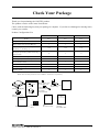
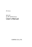
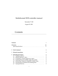
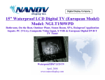
IPC Series
FLAT PANEL DISPLAY
Aluminium-Face Type
(DC12V,6.5"-TFT,LVDS)
FPD-S71VT-DC1
(DC12V,12.1"-TFT,LVDS)
FPD-L71ST-DC1
(DC12V,15.0"-TFT,LVDS)
FPD-H71XT-DC1
User’s Manual
CONTEC CO.,LTD.
Check Your Package
Thank you for purchasing the CONTEC product.
The product consists of the items listed below.
Check, with the following list, that your package is complete. If you discover damaged or missing items,
contact your retailer.
Product Configuration List
FPD-S71VT-DC1
FPD-L71ST-DC1
FPD-H71XT-DC1
Pcs.
Pcs.
Pcs.
Flat panel display
1
1
1
Three-point sems screws (M3 x 6)
1
1
1
1 set
1 set
1 set
2
1
3
The attachment fittings
4
6
8
AC adapter jack fixed clamp
1
1
1
Serial number label
1
1
1
IPC Precaution List
1
1
1
Waterproof packing Precaution List
1
1
1
Product guide
1
1
1
Name
Power supply connector complete set
(Contact…4, housing…1)
Clamp for preventing cables from being
disconnected
(Note)
The manual of this product is being offered as PDF file on the CONTEC’s Web site.
Each cable for this product is not bundled. Purchase it separately.
x4
Flat panel display
The attachment
fittings
Contact
Housing
Three-point sems
screws(M3 x 6)
Clamp for
preventing cables
for being
disconnected
Housing
Product guide
AC adapter jack
fixed clamp
IPC
Precaution List
Warranty
Certificate
Product guide
Waterproof
packing
Precaution List
XXXXXXXXXXXXX
XXXXXXXXXXXXX
Serial number
Warranty Certificate label
FPD-L71ST-DC1, FPD-H71XT-DC1
IPC
Precaution List
Waterproof
packing
Precaution List
i
Copyright
Copyright 2008 CONTEC CO., LTD. ALL RIGHTS RESERVED.
No part of this document may be copied or reproduced in any form by any means without prior written
consent of CONTEC CO., LTD.
CONTEC CO., LTD. makes no commitment to update or keep current the information contained in this
document.
The information in this document is subject to change without notice.
All relevant issues have been considered in the preparation of this document. Should you notice an
omission or any questionable item in this document, please feel free to notify CONTEC CO., LTD.
Regardless of the foregoing statement, CONTEC assumes no responsibility for any errors that may
appear in this document or for results obtained by the user as a result of using this product.
Trademarks
Intel and Celeron are registered trademarks of Intel Corporation. MS, Microsoft and Windows are
trademarks of Microsoft Corporation. Other brand and product names are trademarks of their respective
holder.
ii
FPD-L71ST-DC1, FPD-H71XT-DC1
Table of Contents
Check your package ............................................................................................................................. i
Copyright ............................................................................................................................................ ii
Trademarks ......................................................................................................................................... ii
Table of Contents ............................................................................................................................... iii
1.
INTRODUCTION
1
About the Products ............................................................................................................................. 1
Features ........................................................................................................................................ 1
Customer Support ............................................................................................................................... 2
Web Site ....................................................................................................................................... 2
Limited One-Year Warranty ............................................................................................................... 2
How to Obtain Service........................................................................................................................ 2
Liability ............................................................................................................................................... 2
Safety Precautions .............................................................................................................................. 2
Safety Information ....................................................................................................................... 3
Handling Precautions ................................................................................................................... 3
2.
SPECIFICATIONS
5
Function Specifications ...................................................................................................................... 5
General Specifications ........................................................................................................................ 6
Optical Display Specifications ........................................................................................................... 7
Physical Dimensions ........................................................................................................................... 8
3.
PART NAMES
11
Part Names ........................................................................................................................................ 11
LVDS Input Interface Connector .............................................................................................. 12
DVI-D Input Interface Connector.............................................................................................. 13
USB Touch Panel Connector ..................................................................................................... 14
Dip Switch ................................................................................................................................. 14
Front SW for Backlight Control ................................................................................................ 15
4.
HARDWARE SETUP
17
Installation Requirements ................................................................................................................. 17
Panel Cut ........................................................................................................................................... 18
Attaching the attachment fittings to the Main Unit .......................................................................... 19
FPD-L71ST-DC1, FPD-H71XT-DC1
iii
5.
CONNECTION TO THE HOST COMPUTER
21
LVDS Interface Connection ............................................................................................................. 21
DVI-D Interface Connection ............................................................................................................ 26
Touch Panel Data Communications ................................................................................................. 27
6.
POWER SUPPLY CONNECTION
29
DC Power Supply Input Connector : DC-IN ............................................................................. 29
AC Adapter Jack ........................................................................................................................ 30
AC adapter code removal prevention fitting .................................................................................... 30
7.
LED INDICATORS
31
8.
TOUCH PANEL
33
9.
DISPLAY MODE
35
10.
OPTIONS
37
iv
FPD-L71ST-DC1, FPD-H71XT-DC1
1. Introduction
1. Introduction
About the Products
These products are two inputs (LVDS or DVI-D sign) compatible, panel-mounted, TFT LCD display unit
for use with host computers such as the CONTEC IPC series and SBCs (single board computers).
Touch panel is available via RS-232C (Built-in video cable) or USB connection.
Because its panel attachment is compatible with the predecessor IPC-DT60(panel mount type61) series,
they are transposable.
Features
- LVDS and DVI-D inputs supported panel mount TFT LCD display
LVDS and DVI-D inputs, that are less affected by the interference of noise, are supported for host
computer connection. Because of the digital signal input, up to 5 m of cable length is available. The
video signal and touch panel signal can be connected with one cable depending on the host PC to be
connected.
Full-bright, wide-angle-of-visibility type of liquid crystals capable of displaying up to 16,777,216 colors
on the 15 inches and 262,144 colors on the 12.1/6.5 inches by adopting the lightweight aluminum-made
front.
- Touch panel enables keyboard-less operation.
These products have analog touch panel enabling mouse emulation using driver software.
Touch panel is available via USB connection or optional display cable (built-in video signal and touch
panel signal).
- The panel attachment size compatible with IPC-DT60(panel mount type61) series
Because its panel attachment is compatible with the predecessor IPC-DT60(panel mount type61) series,
they are transposable.
- Front side in IP65-rated dustproof/drip-proof structure
Front side in IP65-rated dustproof/drip-proof structure
- AC adapter, stand and connection cable is available as option.
An optional AC adapter (IPC-ACAP12-02), stand (IPC-SND-03) and connection cable is available to
run the display from the AC power supply, to use as a desktop display and for connection to the host
computer.
*
For more details on host computer or option of this product, contact your retailer.
FPD-L71ST-DC1, FPD-H71XT-DC1
1
1. Introduction
Customer Support
CONTEC provides the following support services for you to use CONTEC products more efficiently and
comfortably.
Web Site
Japanese http://www.contec.co.jp/
English http://www.contec.com/
Chinese http://www.contec.com.cn/
Latest product information
CONTEC provides up-to-date information on products.
CONTEC also provides product manuals and various technical documents in the PDF.
Free download
You can download updated driver software and differential files as well as sample programs available in
several languages.
Note! For product information
Contact your retailer if you have any technical question about a CONTEC product or need its price,
delivery time, or estimate information.
Limited One-Year Warranty
CONTEC Products are warranted by CONTEC CO., LTD. to be free from defects in material and
workmanship for up to one year from the date of purchase by the original purchaser.
Repair will be free of charge only when this device is returned freight prepaid with a copy of the original
invoice and a Return Merchandise Authorization to the distributor or the CONTEC group office, from
which it was purchased.
This warranty is not applicable for scratches or normal wear, but only for the electronic circuitry and
original products. The warranty is not applicable if the device has been tampered with or damaged
through abuse, mistreatment, neglect, or unreasonable use, or if the original invoice is not included, in
which case repairs will be considered beyond the warranty policy.
How to Obtain Service
For replacement or repair, return the device freight prepaid, with a copy of the original invoice. Please
obtain a Return Merchandise Authorization Number (RMA) from the CONTEC group office where you
purchased before returning any product.
* No product will be accepted by CONTEC group without the RMA number.
Liability
The obligation of the warrantor is solely to repair or replace the product. In no event will the warrantor
be liable for any incidental or consequential damages due to such defect or consequences that arise from
Safety Precautions. Understand the following definitions and precautions to use the product safely.
Safety Precautions
Understand the following definitions and precautions to use the product safely.
2
FPD-L71ST-DC1, FPD-H71XT-DC1
1. Introduction
Safety Information
This document provides safety information using the following symbols to prevent accidents resulting in
injury or death and the destruction of equipment and resources. Understand the meanings of these labels
to operate the equipment safely.
DANGER
DANGER indicates an imminently hazardous situation which, if not avoided, will
result in death or serious injury.
WARNING
WARNING indicates a potentially hazardous situation which, if not avoided, could
result in death or serious injury.
CAUTION
CAUTION indicates a potentially hazardous situation which, if not avoided, may
result in minor or moderate injury or in property damage.
Handling Precautions
CAUTION
-
-
-
As this product contains precision electronic components, do not use or store in environments
subject to shock or vibration.
This product is not intended for use in aerospace, space, nuclear power, medical equipment, or other
applications that require a very high level of reliability. Do not use the product in such applications.
If you utilize this product in such usages where high reliability and safety are required as on the
trains, vessels, automotives or crime- or disaster-prevention devices, contact your retailer.
Do not use or store the product in a location such as extremely high or low temperature, rapid
temperature changes, and the place which receives a strong ultraviolet ray.
Example: - Exposure to direct sun
- In the vicinity of a heat source
Do not use or store the equipment in a dusty or humid place.
Do not perform key operations with the touch panel to implement a process that might endanger life
or result in serious damages. Design a system that can cope with incorrect key input operations.
Do not use a sharp-edged object, such as a mechanical pencil, to operate the touch panel in order to
prevent scratching or malfunctions.
Protect the touch panel against shock to prevent damage.
CONTEC is not liable for a product that has been modified by the user.
When the surface or frame of the touch panel has become dirty, wipe it with neutral detergent. Do
not wipe the touch panel with thinner, alcohol, ammonia, or a strong chlorinated solvent.
Do not plug or unplug the connector with the equipment powered on. as doing so may result in a
malfunction or fault.
Some products require configuration settings. Always check these requirements before use. Also,
never set switches or jumpers to other than the specified settings as this may cause a fault.
A characteristic of analog touch panels is that the detected position may vary due to changes in the
ambient environment (temperature and humidity) and changes in resistance values over time. In
such cases, the touch panel should be recalibrated and the calibration data updated.
Regular maintenance is necessary for the backlight on the touch panel and the display for the
longevity parts.
If you discover damaged or missing items, contact your retailer.
FPD-L71ST-DC1, FPD-H71XT-DC1
3
1. Introduction
Use environment
This product operates under the following operating systems:
Windows XP/2000/NT 4.0/98SE/95OSR2
* The touch panel USB interface is only supported on Windows XP/2000/98SE.
Life expectancy of consumable components
*
(1) Backlight--- Display brightness decreases over time with use. The operating life of the backlight
(brightness reduced to 50% of original) is 50,000 hours for all models. (Assuming
continuous operation at 25 degrees centigrade.)
(2) Touch panel--- The operating lifetime of the touch panel is at least 1 million touches (as tested by
mechanical touching under 300g of force at a rate of two presses per second).
CONTEC accepts your request for replacing each consumable in these products as a request for
repair (at an additional cost). Contact your local retailer or CONTEC sales office.
LCD Display Pixel Drop
LCD display may have some pixels being dropped (bright and black spots) below a certain threshold.
Note that this is not a failure or a defect.
Burn-in on TFT Display
*
"Burn-in" may occur if the same display is retained for a long time. Avoid this by periodically
switching the display so that the same display is not maintained for a long time.
Burn-In: Phenomenon characterized by a TFT display as a result of long-time display of the same
screen where a shadow-like trace persists because electric charge remains in the LCD element even
after the patterns are changed.
4
FPD-L71ST-DC1, FPD-H71XT-DC1
2. Specifications
2. Specifications
Function Specifications
Table 2.1. Function Specifications
Specification
Item
FPD-S71VT-DC1
FPD-L71ST-DC1
FPD-H71XT-DC1
Screen
Assembly type
Panel mounted, desktop *1
Screen size
6.5 inches
12.1 inches
15.0 inches
Number of pixels
640 x 480 dots
800 x 600 dots
1024 x 768 dots
Display type
TFT Color LCD
Number of colors
262,144 colors
262,144 colors
16,777,216 colors *4
Brightness control
Adjustment using the front switch or software control from the host
computer
Backlight control
Can be turned on or off by a front switch or via software control from the
host computer.
Display interface
Input signal
specification
LVDS input (26 pin half pitch connector)
DVI-D input (24 pin DVI (Female) connector)
LVDS input
26 pin half pitch connector *2
DVI-D input
Digital RGB (complies with TMDS) *2
Cable length which
5m or less
recommends
Touch panel
Resolution
4096 x 4096
Detection method
Resistive-layer analog method
Touch life expectancy
One million repeated touches
(as tested by mechanical touching under 300g of force at a rate of two
presses per second)
Touch panel interface
Connect to the host computer using either USB *3 or RS-232C.
RS-232C : built-in LVDS/DVI Connector
USB: USB1.1-compliant, TypeB Connector
Touch panel driver (option)
For Windows : IPC-SLIB-01
*1
Optional desk stand IPC-SND-03 allowing desktop installation
*2
Using a cable longer than 5 m may reduce the image quality. The cable should be as short as possible as
degradation. the image quality may result even when the cable is 5 m or shorter depending on the type of host
computer or cable.
*3
The touch panel USB interface is only supported on Windows XP/2000/98SE.
*4
It is 262,144 when connecting the LVDS.
FPD-L71ST-DC1, FPD-H71XT-DC1
5
2. Specifications
Table 2.2. Power Supply Specifications
Item
Power supply input part
Power supply connector
AC adapter jack
Input power supply voltage
Consumption current *1
Consumption current
(power save mode) *1
*1
Specification
FPD-S71VT-DC1
FPD-L71ST-DC1
FPD-H71XT-DC1
4-pin connector for +12 - 24VDC power supply
Corresponding to +12 (±5%) VDC output AC adapter
+12V-24VDC±5%
0.6A (Max.)
1.4A (Max.)
1.6A (Max.)
0.4A (Max.)
When +12VDC is input.
General Specifications
Table 2.3. General Specifications
Item
Specification
FPD-S71VT-DC1
FPD-L71ST-DC1
FPD-H71XT-DC1
Environment
Operating temperature *1
0 - 50ºC (0 - 40ºC when using an AC adapter)
Storage temperature
-10 - 60ºC
Operating humidity *2
10 - 90%RH (No condensation)
10 - 85%RH (No condensation) (When using the AC adapter)
Floating dust particles
Not to be excessive
Corrosive gas
None
Noise
Line noise
AC line: 2 kV *3, Signal line: 1 kV
(IEC1000-4-4Level3、EN61000-4-4Level3)
resistance
Electrostatic
Contact : 4 kV (IEC1000-4-2Level2, EN61000-4-2Level2)
withstanding
Airborne : 8 kV (IEC1000-4-2Level3, EN61000-4-2Level3)
voltages
Vibration resistance
10 - 57 Hz/Single-side amplitude or 0.075 mm
57 - 150 Hz/1.0 G in the X/Y/Z directions for 40 minutes each
(Conforming to JIS C0040 and IEC68-2-6)
Shock resistance
10 G in the X/Y/Z directions for 11 ms; Half-sine wave
(Conforming to JIS C0041 and IEC68-2-27)
Structure
Physical dimension (mm)
210(W) x 40(D) x
316(W) x 46.5(D) x
373(W) x 46(D) x
166(H)
256(H)
304(H)
Panel cut dimensions (mm)
199.0(W) x 155.0(H) 303.0(W) x 243.0(H) 358.0(W) x 289.0(H)
Mountable panel thickness
1.6mm - 7mm
Weight
1.3kg
2.8kg
4.1kg
Waterproofing and dust-proofing Front part conforming to IP65
*1
In the installed angle which is recommended.
*2
Wet-bulb temperature 38ºC or lower.
*3
When using the optional AC adapter IPC-ACAP12-02.
6
FPD-L71ST-DC1, FPD-H71XT-DC1
2. Specifications
Optical Display Specifications
Table 2.4. Optical Display Specifications
Item
Specifications (25ºC Typ. Value)
Condition
Visual
angle
(vertical)
FPD-S71VT-DC1
FPD-L71ST-DC1
FPD-H71XT-DC1
50deg
50deg
50deg
70deg
70deg
60deg
70deg
70deg
75deg
70deg
70deg
75deg
550cd/m2
350cd/m2
250cd/m2
φ=180°
φ=0°
CR≥10
Visual
φ=+90°
angle
(horizontal)
φ=-90°
Surface
brightness
(at center)
Display in
monochrome
Display in white
*1 Surface brightness is a numerical value in a display simple substance.
The brightness that let the touch panel pass serves as about 77% of the above-mentioned numerical
value.
*2 CR = Contrast ratio
Measurement direction
Z
( θ = 0o )
Left
( φ = -90o )
θ
Top
( φ = 180o )
X
Module
φ
Bottom
( φ = 0o )
Y
Right
( φ = 90o )
Figure 2.1. Viewing Range Definition
CAUTION
The above optical specification data shows optical characteristics of the liquid crystal in the display;
the data does not represent the actual view on the display or its viewing angles.
FPD-L71ST-DC1, FPD-H71XT-DC1
7
2. Specifications
Physical Dimensions
FPD-S71VT-DC1
Figure 2.2. Physical Dimensions of Main Unit (FPD-S71VT-DC1)
FPD-L71ST-DC1
CAUTION!
*************
******0.6N*m***
8-M4 TAP
(Maximum tapping
length : 5mm)
CAUTION!
D o n ' t co n n ec t 1 a n d 2 o f
1 2V D C -I N s imu lt an e o us ly.
1 2 V D C -I N* 1 *2 * **
* * ** ** * ** * **
181
21.5
2-M3 TAP
(Maximum tapping
length : 5mm)
302
193
5 41.5
(252)
316
+
5
MODEL : XXXXXXXXXXXXXXXXXX
SERI AL No. : XXXXXXXXXXXXX
INP UT : XXXXXXXXXXXXXXXXXXXXXX
-
DC-IN
12-24VDC
2
1
SW
DVI
7.5
LVDS
USB
100
75
242
100
75
12
(191.5)
256
(97.8)
The s cr ew bolting to rque o f attac hm ent
must be 0.6N-m(MAX)
[mm]
Figure 2.3. Physical Dimensions of Main Unit (FPD-L71ST-DC1)
8
FPD-L71ST-DC1, FPD-H71XT-DC1
2. Specifications
FPD-H71XT-DC1
CAUTION!
*************
******0.6N*m***
8-M4 TAP
(Maximum tapping
length : 5mm)
The screwbolting torque of attachment
100
75
U SB
15
CAUTION!
1 2V DC-I N* 1* 2 ** *
288
** * ** ** ** * **
D on' t co nnec t 1 a nd 2 o f
1 2 VDC -IN s imulta neo usly .
DC-IN
12-24VDC
2
1
SW
DV I
100
75
LV DS
(236.7)
304
(124.85)
mus t be 0.6N-m(MAX)
MODEL : XXXXXXXXXXXXXXXXXX
SERIAL No. : XXXXXXXXXXXXX
INPUT : XXXXXXXXXXXXXXXXXXXXXX
+
208
357
220
21
2-M3 TAP
(Maximum tapping
length : 5mm)
[mm]
5
41
(310.1)
(373)
5
-
Figure 2.4. Physical Dimensions of Main Unit (FPD-H71XT-DC1)
FPD-L71ST-DC1, FPD-H71XT-DC1
9
2. Specifications
10
FPD-L71ST-DC1, FPD-H71XT-DC1
3. Part Names
3. Part Names
Part Names
Screen & Touch panel
-
Power LED
+
Backlight control switch
Up
CAUTION!
*************
******0.6N*m***
The screw bolting torque of attachment
must be 0.6N-m*M AX* .
Back
Left
CAUTION!
Don 't con nect 1 an d 2 of
12VDC-IN sim ultan eou sly.
1
USB touch panel connector
LDVS connector
DVI-D connector
Dip switch
2
MODEL : XXXXXXXXXXXXXXXXXX
SERIAL No. : XXXXXXXXXXXXX
INPUT : XXXXXXXXXXXXXXXXXXXXXX
12VDC-IN*1*2***
************
DC -IN
12 -24V DC
SW
DVI
LVDS
USB
Right side
Power connector
AC adapter jack
Figure 3.1. Part Names
-
+
Figure 3.2. Backlight control switch
FPD-L71ST-DC1, FPD-H71XT-DC1
11
3. Part Names
LVDS Input Interface Connector
It can connect to the host computer which outputs to the LVDS by using the optional LVDS cable. For
more details on the connectable host computer or notes in connection, refer to chapter 5, “Connection to
the Host Computer”.
Table 3.1. LVDS Input Interface Connector
Connector
used
Half pitch 26 pin connector (DX10GIM-26SE or
equivalence to it)
13
1
14
26
Pin No.
*
12
↓ Lower side is display part.
Signal name
Pin No.
Signal name
1
BLK_EN
(+3.3V)
14
RESERVED
2
RXD
15
RESERVED
3
TXD
16
RESERVED
4
DDCCLK
(+3.3V)
17
DDCDATA
(+3.3V)
5
GND
18
GND
6
A_CLK-
19
RESERVED
7
A_CLK+
20
RESERVED
8
GND
21
GND
9
A_TX2-
22
A_TX3-
10
A_TX2+
23
A_TX3+
11
GND
24
GND
12
A_TX0-
25
A_TX1-
13
A_TX0+
26
A_TX1+
Leave "Reserved" pins unconnected.
FPD-L71ST-DC1, FPD-H71XT-DC1
3. Part Names
DVI-D Input Interface Connector
It can connect to the host computer which outputs to the DVI-D by using the optional DVI cable. For
more details on the connectable host computer or notes in connection, refer to chapter 5, “Connection to
the Host Computer”.
Table 3.2. DVI-D Input Interface Connector
Connector
used
24 pin DVI-D
9
Pin No.
*
1
8
17
24
16
↓ Lower side is display part.
Signal name
Pin No.
Signal name
1
TMDS
DATA2-
13
N.C.
2
TMDS
DATA2+
14
+5V
3
TMDS
DATA2
SHIELD
15
GND
4
N.C.
16
HPD
5
N.C.
17
TMDS
DATA0-
6
DDC CLK
18
7
DDC
DATA
19
TMDS
DATA0
SHIELD
8
N.C.
20
TXD
9
TMDS
DATA1-
21
RXD
TMDS
DATA0+
10
TMDS
DATA1+
22
TMDS
DATA0
SHIELD
11
TMDS
DATA1
SHIELD
23
TMDS
CLK+
12
N.C.
24
TMDS
CLK-
Host computer corresponding to the dual link cannot be connected.
FPD-L71ST-DC1, FPD-H71XT-DC1
13
3. Part Names
USB Touch Panel Connector
The USB connector for communication between the host computer and touch panel.
Table 3.3. USB Touch Panel Connector
Connector
used
USB Type B(Receptacle)
2
1
3
4
↓ Lower side is display part.
Pin No.
Signal name
Pin No.
Signal name
1
+5V (INPUT)
3
DATA+
2
DATA-
4
GND
Dip Switch
A DIP switch is located on the left side of the unit.
When using it in a normal way, set it to all OFF (The default factory setting).
CAUTION
Ensure that the power is turned OFF before changing the DIP switch settings.
Table 3.4. Setting a Dip Switch
No.
Setting description
Factory
setting
1
2
OFF
Reserved (Leave this at OFF.)
ON
3
1
2
3
4
5
6
7
8
↓ Lower side is display part.
14
OFF
OFF
4
Reserved (Leave this at OFF.)
OFF
5
Reserved (Leave this at OFF.)
OFF
6
Reserved (Leave this at OFF.)
OFF
7
Reserved (Leave this at OFF.)
OFF
8
Reserved (Leave this at OFF.)
OFF
FPD-L71ST-DC1, FPD-H71XT-DC1
3. Part Names
Front SW for Backlight Control
These products have a SW for backlight control on the front side. Backlight ON/OFF and the brightness
adjustment can be done with this switch.
The backlight can be controlled by the software control from the host computer side.
It turns on or off the backlight.
If there is no video signal input, backlight does not turn on.
All the settings can be reset to the factory defaults by turning on these products while holding down this
key.
+
It raises the brightness one rank up.
-
It lowers the brightness one rank down.
Keeping pushing this button raises the brightness up to maximum.
Keeping pushing this button lowers the brightness down to minimum.
FPD-L71ST-DC1, FPD-H71XT-DC1
15
3. Part Names
16
FPD-L71ST-DC1, FPD-H71XT-DC1
4. Hardware Setup
4. Hardware Setup
Installation Requirements
Distances between this product and Its Vicinity
To maintain the ambient temperature within the installation environment requirement range, provide a
gap of 50mm or more between the main unit and any adjacent equipment.
Side view
Panel
50mm or more
(above)
Bottom view
50mm or more
(Side)
Interface surface
50mm or more
(Bottom)
Panel
50mm or more
(Back)
Figure 4.1. Distances Between Computer and Surroundings
Installed angle which is recommended
Installed angle of this product which is recommended is 0 - 45°. Except for that, the temperature
specification of this product might not be filled.
0°
+θ
-θ
45°
Side view
Figure 4.2. Installed angle which is recommended
FPD-L71ST-DC1, FPD-H71XT-DC1
17
4. Hardware Setup
Panel Cut
Cut the display mount panel in the following dimensions. The four corners of the solid-line rectangle
define the panel cut dimensions.
Figure 4.3. FPD-S71VT-DC1 [6.5 inches] Panel Cut Dimensions and hole position for stud
303 +1
-0
243 +1
-0
R1 or less
Panel thickness range 1.6 - 7mm
[mm]
Figure 4.4. FPD-L71ST-DC1 [12.1 inches] Panel Cut Dimensions and hole position for stud
358 +1
-0
289 +1
-0
R1 or less
Panel thickness range 1.6 - 7mm [mm]
Figure 4.5. FPD-H71XT-DC1 [15 inches] Panel Cut Dimensions and hole position for stud
18
FPD-L71ST-DC1, FPD-H71XT-DC1
4. Hardware Setup
Attaching the attachment fittings to the Main
Unit
(1) Hold the main unit from the outside of the panel.
Figure 4.6. Attaching the attachment fittings to the Main Unit < 1 / 2 >
(2) Hold the attachment fittings from the inside of the panel.
Metal fittings
Panel
Main body
Overtightening screws may result in damage.
Figure 4.6. Attaching the attachment fittings to the Main Unit < 2 / 2 >
FPD-L71ST-DC1, FPD-H71XT-DC1
19
4. Hardware Setup
20
FPD-L71ST-DC1, FPD-H71XT-DC1
5. Connection to the Host Computer
5. Connection to the Host Computer
Purchase individual connection cables as they are not bundled with this equipment.
LVDS Interface Connection
These products can be connected to CONTEC host computer (IPC Series and single board computer
(SBC)) that have LVDS display output. Connect the LVDS connector of supported host computer with
these products using the dedicated LVDS connecting cable.
As for the specific IPC Series or SBC, you need to change the BIOS setting to display it appropriately by
the LVDS input. For more details on this, refer to the manual for each HOST computer.
When connecting to a SBC
LVDS conversion bracket and LVDS cable are required (separately available).
Be sure to connect a conversion bracket that supports each LVDS output pin header connector, and then
connect the LVDS connector of the bracket with these products using a LVDS cable.
Depending on the SBC, two or more LVDS output pin headers are equipped. Be sure to check the
connector reference No. of conversion cable and each SBC in the table below. Then connect it to the
appropriate connector.
Conversion bracket
FPD-30F26F
FPD-20F26F
SBC
Reference
SEH-9450-LAS
LVDS1
SPC-9450-LA
LVDS1
SPC-852x-LA
CNK1
SLC-85xx-LxA
CN15
SPI-855x-LLVAS
CN18
SPI-8550-LA
CN18
SPI-845x-LLVA
CN12
WARNING
When using the SLC-85xx-LxA, SPC-9450-LAS or SEH-9450-LAS. Be sure to connect
FPD-30F26F to the 30 pin LVDS output pin header connector before use.
These SBC which have 20pin LVDS output pin header, be sure to use not the FPD-20F26F but the
FPD-30F26F.
FPD-L71ST-DC1, FPD-H71XT-DC1
21
5. Connection to the Host Computer
When connecting to a SPI-855x/IPC-BX8x0 series
The LVDS output is set to Disabled by default. It is required to change the LVDS output to Enabled via
BIOS menu.
1. Select “Video Features” from “Advanced” menu.
Main Advanced Security Power PC_Health Boot Exit
Reset Configuration Data:
[Yes]
Installed O/S:
[WinXP]
Large Disk Access Mode:
[DOS]
>Cache Memory Features
>Memory Features
>PCI Features
>IDE Features
>Video Features
>LAN Features
>USB Features
>Audio Features
>IO Features
>Keyboard Features
>Boot Features
Figure 5.1. Advanced Menu Screen
22
FPD-L71ST-DC1, FPD-H71XT-DC1
5. Connection to the Host Computer
2. Change “Boot Type” to “CRT+LCD”.
Main Advanced Security Power PC_Health Boot Exit
Video Features
IGD - Device 2:
[Enabled]
IGD - Device 2, Function 1:
[Enabled]
IGD - Memory Size:
[UMA = 8MB]
IGD - Boot Type
[VBIOS Default]
IGD - LCD Panel Type
[1024x768 LVDS]
Video device select :
[Internal]
Internal DDC ROM
[Enabled]
Splash Screen Size
[1024x768]
Figure 5.2. Video Features Screen
FPD-L71ST-DC1, FPD-H71XT-DC1
23
5. Connection to the Host Computer
When connecting to a
SEH-9450-LAS/SPC-9450-LV/SPI-845x-LLVA/SLC-85xx-LxA/SPC-852x-LA/IPC-BX701/IPC-BX9
00/IPC-BX950 series
It is required to set the output resolution to a right one via BIOS according to the supported resolution of
the connected flat panel display.
1. Select the “Advanced Chipset Features”.
Figure 5.3. Advanced Chipset Features Setup
2. Specify the output resolution corresponding to the connected display from the “Panel Number”.
Figure 5.4. Panel Number Setup
24
FPD-L71ST-DC1, FPD-H71XT-DC1
5. Connection to the Host Computer
CAUTION
-
Do not connect it with the DVI-D at the same time. Doing so may provide abnormal screen display.
-
DOS prompt may fail to display the full screen depending on the PC for connection. In such a case,
you can display it by changing the display driver setting to the one of the followings.
1.
2.
3.
Select the "Intel(R) Dual Display Clone" and change the primary device to the notebook.
Select the “twin” on the multiple display setting.
Select the “Notebook” on the single display setting.
Note that the above setting is used when the “Intel Extreme Graphics2” is used. The setting item
may be quite different and depend on the other driver and version.
-
Depending on the following IPC Series or SBC, you may fail to set the VGA (640 x 480) in the
resolution. In such a case, it is required to update the BIOS, so please contact your retailer.
IPC Series : IPC-BX701 Series, IPC-BX900 Series
SBC
: SEH-9450-LAS, SPC-9450-LA, SPI-845x-LLVA, SLC-85xx-LxA
FPD-L71ST-DC1, FPD-H71XT-DC1
25
5. Connection to the Host Computer
DVI-D Interface Connection
Connect the DVI-D input on this unit to the DVI-D connector on the host computer or the PanelLink
connector. You can use a CONTEC IPC series or SBC (single board computer) as the host computer. In
this case, settings are required on each host computer.
Set the LCD type as follows depending on the host computer to be used.
When connecting to a IPC-BX/M360(PCI)C Series
Set the size of the connecting display by selecting “Advanced Chipset Features Setup” – “Panel Type” in
the BIOS setting section.
Example) For FPD-L7xST-DC1 : “800 x 600”
CAUTION
-
If connecting this display to a product with the “AUTO Select” function such as
IPC-BX/M360(PCI)C etc., or to a product with the “plug and play” function such as the
IPC-BX/M630(PCI) series, first connect cables, then turn on the display, always before turning on
the host computer. If the host computer is started before the display, it may not be able to read the
information on the display, and as a result, no screen image may come up.
In this case (e.g. when the display is turned on afterward, when a cable is connected afterward),
specify the display size in the BIOS settings on the host computer.
-
26
Do not connect these products with the LVDS at the same time. When doing so may cause an
abnormal display in the screen.
FPD-L71ST-DC1, FPD-H71XT-DC1
5. Connection to the Host Computer
Touch Panel Data Communications
These connections are used to send touch panel data to the host computer via the USB or RS-232C.
If you use the touch panel via the RS-232C connection, you do not have to use the RS-232C cable
because both LVDS and DVD-D interface includes the RS-232C signal line.
If you use the touch panel via the USB connection, you have to use the USB cable to connect this product
to the USB port on the host computer.
Table 5.1. Example of a USB connection cable (USB Type A (Host) ⇔ Type B (Display) cable)
Model
Maker
Cable length
SANWA SUPPLY INC.
KU20-2H
SANWA SUPPLY INC.
KU20-5H
2m
5m
Note that some types of BOX-PC/SBC require certain care in making a touch panel connection via
RS-232C: followings should be referred to for connecting them with some configuration changes.
- When connecting to SBC
For some SBCs, the DVI/LVDS connector touch panel signals and the pin header output COM ports are
mutually exclusive.
When this product is connected with one of the SBCs listed in the table below, note that the SBC's
corresponding COM port is unavailable irrespective of the use of touch panel.
SBC
I/F
Unavailable SBC Serial Connector
SPC-852x-LA
LVDS
Serial 1 (CNG1)
SPC-8450-LVA
DVI-D
Serial 1 (CN1)
SPI-855x-LLVAS
DVI-D
Serial 1 (CN13)
SPI-845x-LLVA
DVI-D
Serial 1 (CN6)
SPI-815x-LLVA
DVI-D
Serial 1 (CN9)
SLC-8550-LVA
LVDS
Serial 6 (CN5)
SEH-9450-LAS
LVDS
Serial 1 (COM1)
Note that the SBC series products connected by using the conversion bracket FPD-20F26F do not have
the RS-232C in the LVDS interface so the touch panel must be connected via USB.
FPD-L71ST-DC1, FPD-H71XT-DC1
27
5. Connection to the Host Computer
- When connecting to BOX-PC
Note that the following IPC series products do not have the RS-232C in the DVI-D interface so the touch
panel must be connected via USB.
-
IPC-BX950TxD series (DVI-D interface)
For more details on the allocation to RS-232C port No. in the LVDS/DVI-D connector, refer to the
manual for each PC.
CAUTION
-
Touch panel driver software is required to use the touch panel. Purchase optional driver software
[IPC-SLIB-01 for windows or IPC-TPB1-DRV for Windows] or download one from the
CONTEC’s web site.
-
The USB touch panel driver software requires Ver1.52 or later of IPC-SLIB-01.
-
The USB connection can only be used on Windows XP, 2000, or 98SE. Connect via the RS-232C
interface if using a different OS.
-
Use either USB or RS-232C for connecting the touch panel. The touch panel cannot be connected
via both interfaces at the same time.
-
When using the USB connection, the screen image may disappear momentarily when the USB cable
is connected or disconnected and when the computer power is turned ON or OFF.
-
When using the USB connection via a hub, the unit may not operate correctly in some cases
depending on the other USB devices connected to the hub. Please check the operation before using
in practice.
28
FPD-L71ST-DC1, FPD-H71XT-DC1
6. Power Supply Connection
6. Power Supply Connection
These products can connect the DC power or AC adapter for the power supply.
CAUTION
-
Input the power supply to the DC power supply connector only or the AC adapter jack only. Never
supply power to both of them at the same time as it can cause a fault.
-
If you connect a power supply other than the optional AC adapter, be sure to take safety measures
for the power supply, such as overvoltage protection. Use meticulous care not to mistake the
connection polarity or voltage of the power supply as it may break the equipment, the power supply,
or both.
-
When power cycling, wait for more than ten seconds before use.
DC Power Supply Input Connector : DC-IN
When connecting the power supply, ensure that the supply satisfies the specifications below.
Power supply voltage
Power supply capacity
:
:
12 - 24VDC±5%
12V 3A or more, 24V 1.5A or more
Please process it as shown in the table below by using an attached housing and contact. Then connect it.
Table 6.1. DC power supply connector
Connector type
9360-04P (mfd. by ALEX)
Pin No.
Signal name
GND
4
3
1
2
GND
2
1
3
12 - 24V
4
12 - 24V
Applicable connector of cable side
Housing
Contact
: 9357-04 (mfd. by ALEX) or 5557-04R (mfd. by MOLEX)
: 4256T2-LF (mfd. by ALEX) or 5556 (mfd. by MOLEX)
Cable
: AWG#18 - 24
Crimp tool : 57026-5000 (UL1007) (mfd. by MOLEX), 57027-5000(UL1015) (mfd. by MOLEX)
Rise time of power supply
Voltage
1 - 30mS
12V
Time
Figure 6.1. Graph of Rise Time of Power Supply
FPD-L71ST-DC1, FPD-H71XT-DC1
29
6. Power Supply Connection
AC Adapter Jack
The AC adapter jack is used to connect the AC adapter [IPC-ACAP12-01] available as an option. Do not
connect any AC adapter other than the option.
+12V
GND
Figure 6.2. AC Adapter Jack
AC adapter code removal prevention fitting
(1) Insert the plug of AC Adapter.
(2) Tighten the screws on the attachment fitting.
Figure 6.3. Code Removal Prevention Fitting
30
FPD-L71ST-DC1, FPD-H71XT-DC1
7. LED Indicators
7. LED Indicators
The POWER LED on the front face indicates each state of the display as follows:
Table 7.1. LED Indicators
LED status
Description
OFF
The power supply off or these product not started normally
Green(ON)
Normal operation
Green (Flashing)
Power save mode
Orange (Flashing)
No signal input *1
*1
These products enter the power save mode automatically when no
signal has been inputs.
FPD-L71ST-DC1, FPD-H71XT-DC1
31
7. LED Indicators
32
FPD-L71ST-DC1, FPD-H71XT-DC1
8. Touch Panel
8. Touch Panel
This equipment has a touch panel that enables keyboard-less, mouse-less operations by communication
with the host computer using the RS-232C cable.
Touch panel
MENU
-
+
ESC
POWER
Touch panel controller
Host PC
CPU
Touch panel
Communication controller
INT
Serial communication
Figure 8.1. Touch Panel and Block Diagram
Data input at the touch panel is processed by the touch panel controller and passed to the host PC via the
serial port on the CPU in the controller.
Before the touch panel can be used, touch panel driver software must be installed. Note that the driver
software is not bundled with this product. Purchase the one separately or download it from the
CONTEC’s web site.
For further details, refer to the READ_ME file for each driver.
<Option touch panel driver>
Windows XP/2000/NT 4.0/98SE/95OSR2
FPD-L71ST-DC1, FPD-H71XT-DC1
: IPC-SLIB-01
33
8. Touch Panel
34
FPD-L71ST-DC1, FPD-H71XT-DC1
9. Display Mode
9. Display Mode
This equipment supports the following display modes:
Dot clock
(MHz)
Horizontal
frequency
(kHz)
Vertical
frequency
(Hz)
VGA
640 x 480
25.18
31.47
60
VESA
800 x 600
40.00
37.88
60
x
VESA
1024 x 768
65.00
48.36
60
x
FPD-H71XT-DC1
Number of
pixels (dot)
FPD-L71ST-DC1
Video
mode
FPD-S71VT-DC1
Display
Ο
Ο
Ο
x
x: Display is unavailable
Ο: Display available (Depending on the scaling function of host PC)
:
Recommended resolution (mode)
CAUTION
-
The number of display pixels in the LCD is 640 x 480 dots on FPD-S71VT-DC1 model, 800 x 600
dots on FPD-L71ST-DC1 model and 1024 x 768 dots on the FPD-H71XT-DC1 model.
When the input has a resolution lower than the number of display pixels of each model whether or
not an auto scaling function from the host PC exists, etc.,. Note, in this case, that the display quality
is therefore degraded in clearness compared to the screen displayed at the resolution that matches
the number of display pixels of the LCD and the display area is not displayed in the full screen
because it exists in the center of screen.
-
The screen will not possible to be likely to display correctly if the resolution and frequency do not
match one of the supported display modes.
FPD-L71ST-DC1, FPD-H71XT-DC1
35
9. Display Mode
36
FPD-L71ST-DC1, FPD-H71XT-DC1
10. Options
10. Options
Screen protective sheets
-
IPC-CV6
: 6.5-inch [FPD-S71VT-DC1] screen protective sheets (10 sheets)
-
IPC-CV12
: 12.1-inch [FPD-L71ST-DC1] screen protective sheets (10 sheets)
-
IPC-CV15
: 15-inch [FPD-H71XT-DC1] screen protective sheets (10 sheets)
Display cable only for DVI-D
-
IPC-DVI/D-020
: DVI-D cable (2m)
-
IPC-DVI/D-050
: DVI-D cable (5m)
Display cable only for LVDS
-
FPD-26M26M-005 : LVDS cable (0.5m)
-
FPD-26M26M-020 : LVDS cable (2m)
-
FPD-26M26M-050 : LVDS cable (5m)
Conversion cable for SBC *1
-
FPD-20F26F
: LVDS connector conversion cable (20-pin header connector)
-
FPD-30F26F
: LVDS connector conversion cable (30-pin header connector)
*1 LVDS cable FPD-26M26M-005, FPD-26M26M-020 or FPD-26M26M-050 is required separately.
Driver
-
IPC-SLIB-01
: Driver & Utility Soft Set (CD-ROM version) *2
*2 You can download the driver from the CONTEC Web site (free of charge)
Others
-
IPC-ACAP12-02
: AC ADAPTER (DC12V)
Input
: Voltage is 90 - 264VAC, current is 1.3A or less
(when the input voltage is 100VAC)
Output
: Voltage is 12VDC, current is 4A.
-
IPC-SND-03
: Desk stand
Recommendation Cable (Maker: SANWA SUPPLY INC.)
-
KU20-2H
: USB cable for touch panel (2m)
-
KU20-5H
: USB cable for touch panel (5m)
FPD-L71ST-DC1, FPD-H71XT-DC1
37
FPD-S71VT-DC1
FPD-L71ST-DC1
FPD-H71XT-DC1
User’s Manual
CONTEC CO.,LTD.
August 2015 Edition
3-9-31, Himesato, Nishiyodogawa-ku, Osaka 555-0025, Japan
Japanese http://www.contec.co.jp/
English http://www.contec.com/
Chinese http://www.contec.com.cn/
No part of this document may be copied or reproduced in any form by any means without prior written
consent of CONTEC CO., LTD.
[12092008]
[10062008]
[08052015_rev3]
Management No.
Part No.
A-51-623
LYJV583