1
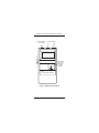
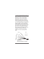
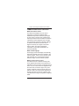
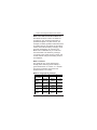
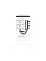
Model 413 ELF Magnetic Field Meter User’s Manual User’s Manual Model 413 ELF Magnetic Field Meter Methods and apparatus disclosed and described herein have been developed solely on company funds of Lake Shore Cryotronics, Inc. No government or other contractual support or relationship whatsoever has existed which in any way affects or mitigates proprietary rights of Lake Shore Cryotronics, Inc. in these developments. Methods and apparatus disclosed herein may be subject to U.S. Patents existing or applied for. Lake Shore Cryotronics, Inc. reserves the right to add, improve, modify, or withdraw functions, design modifications, or products at any time without notice. Lake Shore shall not be liable for errors contained herein or for incidental or consequential damages in connection with furnishing, performance, or use of this material. Rev. 1.2 P/N 119-022 27 Sept 2000 Model 413 ELF Magnetic Field Meter User’s Manual LIMITED WARRANTY Lake Shore Cryotronics, Inc. (henceforth Lake Shore), the manufacturer, warrants this product to be free from defects in material or workmanship for a period of twelve (12) months from the date of shipment. During the warranty period, under authorized return of instruments or component parts to Lake Shore freight prepaid, the company will repair, or at its option replace, any part found to be defective in material or workmanship, without charge to the Owner for parts, service labor or associated customary shipping cost. Replacement or repaired parts are warranted for only the unexpired portion of the original warranty. All products are thoroughly tested and calibrated to published specifications prior to shipment. Calibration Certifications are offered for six month periods only. Where such documentation must be updated, a re-certification service is offered by Lake Shore at a reasonable cost. LIMITATION OF WARRANTY This warranty does not apply to defects resulting from improper or inadequate maintenance, unauthorized modification or misuse, operation outside of the environmental specifications for any product or part or buyer-supplied software interfacing. This warranty is in lieu of any other warranties, expressed or implied, including merchantability, or fitness for a particular purpose, which are expressly excluded. The owner agrees that Lake Shore’s liability with respect to this product shall be set forth in this warranty, and incidental or consequential damages are expressly excluded. CERTIFICATION Lake Shore certifies that this product has been inspected and tested in accordance with its published specifications and that this product met its published specifications at the time of shipment. The accuracy and calibration of this product at the time of shipment are traceable to the United States National Institute of Standards and Technology (NIST); formerly known as the National Bureau of Standards (NBS) Copyright © 1996, 1997, and 1999 by Lake Shore Cryotronics, Inc. All rights reserved. No portion of this manual may be reproduced, stored in a retrieval system, or transmitted, in any form or by any means, electronic, mechanical, photocopying, recording, or otherwise, without the express written permission of Lake Shore. A Model 413 ELF Magnetic Field Meter User’s Manual INTRODUCTION The Lake Shore Model 413 3-Axis Extremely Low Frequency (ELF) Magnetic Field Meter is a batterypowered, hand-held Gaussmeter that measures a variety of ELF sources: • AC Power Lines • Appliances • Computers • Video Display Terminals • Office Equipment • Other Electrical Equipment The Model 413 uses three internal sensors at right angles to each other to evaluate and display a wide range of ELF magnetic fields, independent of measurement angle. The instrument uses an analog-to-digital converter and microprocessor to accurately compute and display the vector magnitude of the magnetic flux density in milligauss. It automatically adjusts to the measurement range offering the best resolution, yielding a wide dynamic measurement range of 0.1 to 1999 mG with a typical accuracy better than 2%, sufficient for characterizing most electrical and electronic equipment. Normally, the unit provides 50 hours of continuous use with a standard 9 volt alkaline battery. A low battery indicator signals users when about 1 hour of measurement time is available before the battery needs replacing. Features include a switchable single-axis mode to display the individual vector components, analog output, DC (recorder) output, and an optional display in microtesla (µT). The instrument comes with a padded, imitation leather case, and a one year warranty covering both parts and labor. 1 Model 413 ELF Magnetic Field Meter User’s Manual Single Axis Mode Pushbutton Analog Outputs A D On milligauss Off Approximate Location and Orientation of 3-Axis Sensors Y Z X 3-Axis ELF Electromagnetic Field Meter Figure 1. Model 413 Front Panel 2 Model 413 ELF Magnetic Field Meter User’s Manual Features • Hand-held, Compact, and Light Weight • 3-Axis Operation • Autoranging (199.9 and 1999 mG) • 0.1 mG Resolution • Wide Frequency Response • Low Battery Indicator • Single-Axis Mode • Two Analog Outputs • One Year Warranty CONTROLS Power. Controls power to the unit. Turn switch On (up) to power the unit. Turn switch Off (down) to turn power off. Single-Axis Pushbutton. Activates single axis mode. Push button once for X axis reading, again for Y axis, again for Z axis, and again to return to normal display. DISPLAY milligauss. The numeric display is in milligauss (mG). A milligauss (mG) is 1/1000th of a gauss (G). The unit measures in two ranges: 0 to 199.9 mG, or 0 to 1999 mG. The decimal point automatically moves to the best field range. BAT. The BAT symbol displays when the 9 volt battery needs replacement. NOTE: The term “magnetic field” is used loosely throughout the manual. All references to magnetic field levels in this manual actually refer to the “magnetic flux density,” which has (CGS) units of milligauss (mG). 3 Model 413 ELF Magnetic Field Meter User’s Manual ANALOG OUTPUTS Z-Axis Output Jack. Labeled A. Provides 5 mV/mG output corresponding to Z-axis only, with 1 volt full scale at 199.9 mG. DC Output Jack. Labeled D. Provides 10 m V/mG output with 2 volts full scale at 199.9 mG. Output corresponds to whatever currently displays and updates every 400 msec (2.5 times per second). The 3-Axis Advantage The Model 413 3-axis measurement method prevents measurement errors due to improper instrument orientation, a problem associated with single-axis instruments. With the Model 413, it is virtually impossible to get an erroneous reading of the magnetic field. Inexperienced and non-technical users benefit from the ease of use of the Model 413, while experienced users appreciate the ability to make accurate measurements and field surveys quickly and confidently. WARNING: Never extend your hands or the instrument into live high voltage circuits. Turning the Instrument On To operate the Model 413, first turn the ON/ OFF switch ON (up). The instrument performs a self-test and displays “-188.8” for about 2 seconds, verifying proper operation. After the power-on sequence finishes, the display indicates the magnetic field reading in mG. 4 Model 413 ELF Magnetic Field Meter User’s Manual Normal Operation Bring the instrument into the vicinity of ELF magnetic fields and note the magnetic field level. The three internal magnetic field sensors are located just below the LCD display. The display indicates the magnetic field level at that point in space. Instrument rotation about that point results in no changing field indication as long as the magnetic field is constant across the dimensions of the internal sensors. Some degree of directionality occurs in near fields, where the magnetic field level changes rapidly over distances comparable to the dimensions of the instrument. In far fields, where the magnetic field is essentially constant, directionality of the instrument is typically less than 1%. Single-Axis Mode The Model 413 can display the vector components of the magnetic flux density, Bx, By, and Bz, in mG. When placed in the singleaxis mode, an arrow symbol appears in the upper-left area of the LCD. It disappears when the Model 413 is returned to triaxial (default) mode. To activate single-axis mode: without moving the instrument, press the pushbutton on the top panel firmly until the display blanks, then release. After blanking for about 0.5 seconds, the display indicates the Bx component. 5 Model 413 ELF Magnetic Field Meter User’s Manual Press the pushbutton a second time until the display blanks, release, and the display indicates By. Press it a third time until the display blanks, release, and the display indicates Bz. Finally, press it once more to reset the instrument and enter triaxial mode. In normal triaxial operation, the unit indicates the correct magnetic field value regardless of physical orientation. However, single axis readings depend on the coil angle in relation to the magnetic field. Maximum output occurs when the flux vector is perpendicular to the plane of the coil. The greater the deviation from from right angles in either of three axes, the larger the error of the reading. For example, a 5° variance on any one axis causes a 0.4% error. See the illustration below. 29.3% B 45° 13.4% 30° 6.0% 20° 3.4% 15° 1.5% 10° 0.4% 5° 0% 0° Error Deviation from Perpendicular (θ) Effect of angular variations on percentage of reading error where % Error = (1 cos θ) 100 6 Model 413 ELF Magnetic Field Meter User’s Manual COMMON OPERATIONAL QUESTIONS What does 3-Axis mean? The Model 413 displays the sum vector magnitude of magnetic readings taken simultaneously in three axes at right angles to each other. The three-axis measurement method provides all the information needed to calculate the actual magnetic field. A singleaxis gaussmeter requires individual readings in all three orientations, with the sensor aligned at exactly 90° angles at the same point in space, and vector magnitude calculation to equal what the Model 413 does automatically. What is Autoranging? Autoranging means the display automatically places the decimal point of the reading in the correct position. There are two ranges: 199.9 mG and 1999 mG. The automatic change between ranges occurs at about 160 mG. Where are the sensing coils? The Model 413 has 3 internal sensing coils. Their approximate position and orientation is indicated on the front panel. Looking at the top of the unit, the x-axis sensor is aligned across the meter face, from left to right. The y-axis sensor is aligned across the meter face from bottom to top. The z-axis sensor alignment is through the meter, from front to back. These coils work best in large, low-gradient magnetic fields. 7 Model 413 ELF Magnetic Field Meter User’s Manual Does movement affect the reading? Yes. The Model 413 must be stationary to take a reading. Moving the Model 413 couples the 500 mG field of the Earth into the coils and gives erroneous readings. Does orientation affect the reading? Under normal triaxial operation, field rotation has only minor effect on the resulting reading. However, in Single-Axis Mode, orientation is critical. MAGNETIC TERMINOLOGY QUESTIONS What is an Electromagnetic Field? Although you cannot see it, there is an electric field around everything with an applied voltage, and a magnetic field around everything that conducts current. The combined effect is called the electro- magnetic field. This includes power lines, electric cords, electric appliances, TVs, vacuum cleaners, etc. Remember the iron filings on paper with a magnet underneath experiment? The filings would line up corresponding to the magnetic field shape. What type of field does the unit measure? The Model 413 measures only the magnetic portion of an extremely low frequency (ELF) AC field. It does not measure electric fields or DC magnetic fields. 8 Model 413 ELF Magnetic Field Meter User’s Manual What is the difference between DC & AC? DC stands for Direct Current. DC fields are unchanging, such as those produced by a permanent magnet or by DC currents. For example, the Earth generates a DC field which is typically 500 mG. AC stands for Alternating Current. AC fields are always changing, such as those generated by AC currents. The Model 413 is calibrated only for continuous sine wave fields. The electricity running to your home is AC. Inside a home or office, the normal ambient background reading is about 0.4 milligauss. What is a Gauss? The gauss (G) is a unit of magnetic flux density (often refered to as the B field). A gauss is defined as 10-4 teslas, or 1 maxwell per square centimeter. Named for Karl Fredrich Gauss (1777-1855). What are some typical readings? Appliance Can Opener Computer Monitor Microwave Oven Television Toaster Vacuum Cleaner At 4 in. 1300 to 4000 mG 50 to 600 mG At 12 in. 30 to 300 mG 3 to 30 mG At 36 in. 0.5 to 7 mG <1 to 2 mG 600 mG 90 mG 5 mG 5 to 100 mG 10 to 60 mG 230 to 1300 mG 0.4 to 20 mG 0.6 to 7 mG 20 to 200 mG <0.1 to 1.5 mG <0.1 mG 1 to 20 mG 9 Model 413 ELF Magnetic Field Meter User’s Manual CIRCUIT DESCRIPTION (See Figure 2) ELF Amplification/Detection Circuitry Three independent ELF amplifier/detection chains provide AC voltages proportional to the vector components of the RMS magnetic field for ELF sine waves. Each chain consists of an air wound sensing coil, followed by three stages of AC amplification and filtering. Analog-to-Digital (ADC) Conversion A 4-channel Analog to Digital Converter (ADC) converts AC voltages to a 12-bit digital data word. In addition to the x, y, z components of the magnetic field, the fourth channel of the ADC senses the battery voltage. Microprocessor and Support Circuitry The heart of the Model 413 is a CMOS microprocessor. During each measurement cycle, it initiates data transfer from the ADC, computes the vector magnitude of the magnetic field, and transfers results to the LCD via the display driver. The microprocessor also senses over and under range conditions, and adjusts AC amplifier gains accordingly. It recognizes entry into singleaxis mode, and displays only the appropriate vector component of the magnetic field. Timing circuitry synchronizes the measurement cycle to repeat every 400 msec. 10 Model 413 ELF Magnetic Field Meter User’s Manual Bx A Amp Variable Gain Amp Buffer Amp Vx Gain Adjust By A Amp Variable Gain Amp Buffer Amp Reference Vy Gain Adjust Bz A Amp Variable Gain Amp Buffer Amp Analog to Digital Converter (ADC) Low Battery Detect Vz Gain Adjust Microprocessor Display Driver On/Off Switch Power Supplies 9 volt Battery Figure 2. Model 413 Block Diagram 11 Model 413 ELF Magnetic Field Meter User’s Manual SPECIFICATIONS Ranges: 199.9 mG, 1999 mG (Autoranging) Resolution: 0.1 mG on 199.9 mG Range; 1 mG on 1999 mG Range Accuracy: 1% ±1 digit typical from 50 to 60 Hz. The instrument is RMS responding and calibrated to sine wave at 60 Hz. Accuracy Over Expanded Frequency Range: >60 Hz. but <300 Hz: ±5%; 40 – 50 Hz. and 300 – 400 Hz: ±10%; 20 – 40 Hz. and 400 – 2000 Hz.: +10% to –30%. Analog Output, Z-Axis waveform only: 5 mV/mG; 1 volt full scale at 199.9 mG. Output impedance is 4 kΩ. DC Output: 10 mV/mG; 2 volts full scale at 199.9 mG. Output impedance is 4 kΩ. Directionality: ±1% (typical) for all measurement angles (triaxial mode). Sensor Type: 3 × 750 turns of #38 Copper, 0.29 inch diameter air core. Display: 3½ digit Liquid Crystal Display (LCD) Battery Type: 9-volt Alkaline Battery. Replace only with an alkaline battery (Duracell MN1604, Eveready 522, or equivalent). Battery Life: 50 hours, typical use (to 5.2 volts minimum) using standard 9 volt alkaline battery. Operating Temperature Range: –10 to +50 °C (14 to 122 °F) Operating Relative Humidity: 90% at +40 °C (104 °F). Storage Temperature Range: –20 to +85 °C (–4 to 185 °F). Storage Relative Humidity: 95% up to +60 °C (140 °F). Dimensions: 15.2 cm x 8.3 cm x 3.6 cm (6 × 3.3 × 1.4 inches) Weight: 200 grams (7 ounces). The unit is not waterproof. 12 Model 413 ELF Magnetic Field Meter User’s Manual BATTERY REPLACEMENT The unit normally provides about 50 hours of continuous use with a 9-volt alkaline battery. When the battery level falls below 5.5 volts, BAT appears in the display, indicating a low battery. About 1 hour of measurement time remains before accuracy degrades. Replace the battery as soon as possible. To remove the battery, turn the Power switch OFF, turn the unit over. Use a small screwdriver to remove the bottom door in the enclosure. Carefully disconnect the old battery, connect a new battery, then replace the back cover. IN CASE OF TROUBLE If the instrument fails to turn on or behaves unpredictably, replace the battery. This usually solves most problems. There are no locally serviceable parts in the Model 413. If you are experiencing problems, contact the factory at the phone numbers or e-mail addresses on the back of this manual. To return a unit, obtain a Return Goods Authorization (RGA) number from a factory representative. Lake Shore requires the following information before attempting any repair: 1. 2. 3. 4. Instrument model and serial number. Name, company, address, & phone number. Malfunction symptoms. RGA number. Ship unit to Lake Shore at Customer expense. Lake Shore will pay for shipping to return units under warranty. If possible, use original packing material for reshipment. If not available, consult Lake Shore for packing instructions. 13 Model 413 ELF Magnetic Field Meter User’s Manual Lake Shore Cryotronics, Inc. 575 McCorkle Blvd. Westerville, Ohio 43082-8888 USA E-Mail Addresses: [email protected] [email protected] Visit Our Website: www.lakeshore.com Fax: (614) 891-1392 Phone: (614) 891-2243