1
NEC
Electra – 616
(With Addendum-001)
CONTENTS
Page
110
Installation
130
140
150
c
160
. . . . . . . . . . .. . . . . . . . . . . .
1100-1
Physical Environment of Equipment
110.1
120
Site Requirements
Electrical
and Grounding
120.1
AC Power
120.2
Grounding
Other
Considerations
. . . . . . . . . . . . . . . .
100-l
. . . . . . . . . . .. . . . . . .. . . . . . . .. . . .
100-2
Requirements
Requirements
130.1
Electrical
130.2
Pre-installation
130.3
Additional
Specifications
Requirements
Noise Generators
Site Survey
Equipment
. . . . . . . . . . . . . . . . . . . . . . . . . . . . .
140.1
System
Capacity
1402
Cabling
Requirements
140.3
Power Requirements
440.4
Surge Protection
140.5
Environmental
140.6
CO/PBX
140.7
Dimensions
140.8
Network
140.9
Visual and Audible
140.10
Dialing
140.11
External
.. . . .
100-2
Conditions
Line Type
and Weight
and Control
Specification
Equipment
General
150.2
Equipment
_.
Interfacing
. . . . ..*........a...*............
List of Equipment
150.4
lndhtions
100-5
Information
Description
System Configuration
. . . . . . . . . . . . . . . . . . . . . .. . . . . . . .
160.1
To Determine
Required
Equipment
1602
To Determine
Optional
Equipment
100 -7
SECTION
p
110
Installation
110.1
Physical
chosen
unit>.
1.
2.
t’
100
GENERAL
Site Requirements
Environment
of
The following conditions
for mounting the central
120.2
Equipment
should be met at the site
equipment (Key Service
Requirements
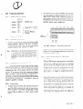
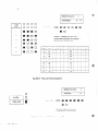
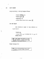
The KSU must be well-grounded.
If a good conduit
ground is not present at the dedicated AC outlet, the
following steps should be taken:
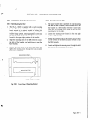
The KSU should normally be wall-mounted to protect
against accident or flooding. Where possible use of a
wooden backboard is recommended for this purpose.
Provide a suitable waterpipe ground in accordance with
the local operating (telephone) company procedures.
2.
The KSU should not be located directly beneath pipes
due to the possibility of leaks or condensation causing
damage.
If no waterpipe is available, a ground rod should be
installed in accordance with local operating company
procedures.
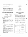
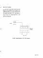
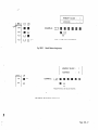
3.
In the case where a ground other than conduit ground
is used a grounding terminal is provided on the ES-6 -1
as shown below in Figure 120- 1.
The area in which the KSU is located must be free of:
corrosive or inflamable gases, excessive chemical or industrial dusts, and other materials which could cause
hazard to personnel or to the proper functioning of the
equipment.
4.
Heat and humidity must be within the limits found in
Section 140 “Specifications”
in this manual.
Although its virtually noiseless operation allows a wide
choice of installation sites, care should be taken that
the KSU not present a hazard to office traffic. For
purposed of economy a central location (to minimize
cabling) is often preferable.
720
Electrical and Ground
120.1
AC Power
1.
Grounding
1.
3.
5.
INSTALLATION
‘1
/
#T
//
PS-6-l
PSU
I
I
Requirements
Requirements
They system should have a dedicated
separately fused for 15 AMPS.
117V AC outlet
Fig. 120-l
2.
The AC outlet should be a standard
type which provides conduit ground.
3.
The AC power must be within the limits found in Section 140 “Secifications” in this manual.
4.
If the AC outlet is subject to power surges, it is recommended that the best locally available AC surge
protection be installed.
Qutsideview
of ES-G-1
12SV three-prong
Page 108-l
- “g-‘
:a;>;
3
...+
.5>
__._
‘P
^‘2:
/
.+iy
:,.
:ig;
‘?:9
._>.
130
Other
130.1
140
Consideratiaons
Electrical
140.1
Noise Generators
;y
Specifications
System
,’
:;
Lt..
Capacity
:
equipment,
such as welding machines,
thyrister-driven
power supplies, large electrical motors, etc.
generate electrical noise. As a stored program machine the
Electra-616
System is vulnerable to this noise. When this
type of machine is present at an instahation, the following
precautionary steps are urged:
The Electra-616
Certain
1.
Locate KSU, telephone
these machines.
sets, and cabling
away from
2.
If cables must pass near these machines,
cabIe with the shield grounded.
use shielded
3.
Ensure all machines of this type are well-grounded
separate ground to minimize noise interference.
to a
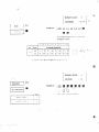
CO/PBX Lines
6max.
Intercom
2 max.
and External Paging Path
Station
Sets
Pre-installation
Additional
Door Phones
2 max.
1.
Cabling
3)
Twisted 2-pair
cable
Twisted
1 -pair cable
- Door Phone:
Twisted
1-pair cable
Maximum
24AWG
Loop Resistance
Set:
and Cable Length
at
40 ohms, 700 ft. (21Om)
- BLF Console:
40 ohms, 700 ft. (21Om)
- Door Phone:
40 ohms, 700 ft. (210m)
Maximum Cable Length at 22AWG
* Key Telephone
2.
Set:
- BLF Console:
- Key Telephone
Equipment
Sets, BLF Con-
Required Cable
- Key Telephone
2)
.k.
7,
Requirements
Cabling required for Key Telephone
soles, Door Phones is as follows:
Site Survey
In addition to electronic station equipment and
the KSU and their contents, other equipment is required.
This includes cables, modular connecting jacks, quickconnect blocks (or smimlar apparatus), etc. This additional
equipment must be locally supplied.
Page 100-2
16 max.
2 max.
Since a pre-installation
survey is generally required
to plan for application and installation,
a check of the
matters covered so far in this section at this time will prevent later problems.
130.3
1 max.
BLF Consoles
1)
130.2
Paths
Internal
140.2
x
system capacity is as follows:
Set:
1,150 ft. (35Om)
- BLF Console:
1,150 ft. (35Om)
- Door Phone:
1,150 ft. (35Om)
BLF Consoles require a local power supply (provided
with each unit), which plugs into a 117V AC outlet.
The cable provided with these units is 6 feet in length.
I
3.
(~__-___-.~-___./
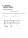
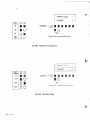
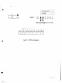
Fuse Replacement
Note:
Replace fuses in accordance
Table 140-l
with Table 140- 1.
Fuse Specifications
For PS-6-1 and KSI-S
140.5
7his is NOTa recommendation
that more than one
set of protectors be installed on CO lines at instailation premises. Improper installation of additional
protection can be a serious safety hazard.
Environmental
1.
Conditions
Temperature:
+32” F- 104°F (O”C-
pperating:
40°C)
Note 1:
FI is 1/4”x I-1/4”size normal blown glass tube or
ceramic fuse. Buss 3A G 125 V., 4A fuse.
Note2:
KSI-S Fl - F8 are 13/64” c 45164” (S mm x 20
mm) size normal blown glass tube fuse. Buss GMA
Recommended
2.
long term:
+50”F-
90°F
Humidity:
Operating
10 - 90 percent
I25 V., O.SA fuse.
Do not install any ‘slow blow” fuses in the ES-6-I
..
140.6
CO/PBX Line Type
KSU.
CO/PBX Line Type:
140.3
Power Requirements
140.7
1. AC Input
and Weight
KSU
- 117V AC f 1O%, SO or 60Hz + 1O%, single phase
ES-6-I
W/PSU
490(W) x 195S(D)x
40 Lbs (I 8kg)
. Max. current draw:
ET-6-I
TEL
210(W) x 222(D) x 82(H)mm,
2.9 Lbs (1300g)
EB-6-1
BLF
75(W) x 222(D) x 82(H)mm,
1.3 Lbs (600g)
* Dedicated
‘*a
Dimensions
2 wire, loop start
4.OA
outlet separately fused at 15A max.
2. Power Supply Outputs
(PS-6 - 1)
DC Voltage
3.
+5v
+ 0.25v
4.OA
+12v
5 O.5V
1.2A
+24V
it 1 .QV
2.OA
+41v
* l.OV
1.4A
Output
Voltage:
Max. Output
140.4
140.8
BLF Console Power Supply
Current:
100(W) x 132(D) x 31.5(H)mm,
0.4 Lbs (200g)
DP-6-1
Door Phone
Max. current
1.
Network
and Control
Control
. Control:
Stored program
. Central processor:
8085A
. Microprocessor
pCOM43N (4 bit onechip microcomputer)
in keyset:
9vDC
0.3A
Surge Protection
If an installation is subject to AC power surges it is
recommended that the most effective locally available form
of surge protection be supplied. CO Lines are protected by
the local operating (telephone) company. It is recommended that the most effective locally available form of protection be installed on CO/PBX lines by the local operating
(telephone) company.
421(H)mm,
. Clock (KSU-keyset):
33kHz
. Transmission data:
(from KSU to keyset)
9 bits
. Scanning time for each
keyset:
Every SO msec.
. Number of cable pairs from
KSU to each station:
. For keyset, one pair:
2 pair wire for keyset
one pair:
Voice and signalling
Data sending and receiving
. For Door Phone, one pair:
Voice and signalling
. For BLF, one pair:
Data receiving
Page 100-3
2.
2)
Network
- Matrix:
Single stage, non blocking C-MOS switch ar-
Intercom
call
- Calling signal for
called station:
Voice signaIling after
tone burst (580Hz,
0.75 sec.)
* Ringback tone:
580Hz,O.75
- Busy tone:
580Hz,
0.5 sec. ON/OS sec.
OFF
- Call waiting tone:
1200Hz,
0.5 sec. ON/O.5 sec.
OFF
- Override tone:
58OHz, 0.75 sec.
- Error tone:
1200Hz,
0.25 sec. ON/O.25 sec.
OFF
* Store speed dial tone:
580Hz
ray
Electronic circuit using
custom LSI (Equivalent
to 500 type standard
network)
. Keyset network:
- Transmitter
Receiver :
3.
Dynamic type
(Equivalent to 500 type
standard telephone
transmitter and
receiver)
and
Transmission
More than 75 dB for
300-3, SOOkHz
- Cross talk attenuation:
Less than 1.8 dB at
- Insertion loss,
station to trunk:
140.10
IkHZ
1.
140.9
1.
Visual and Audible
Dialing
Spxification
Dial Pulse Address Signalling
Indications
a)
Pulse rate:
10 pps or 20 ppS
b)
Percent break:
61 t 3 percent
c)
Interdigital
800 msec.
Visual
Lamp indications
of a Keyset are as follows:
* Idle condition:
Not lit
- Busy CO/PBX and
intercom path:
Steady light
- Incoming CO/PBX and
intercom call:
Flashing light at 601PM
* Call hold CO/PBX:
Winking light at
‘120IPM
- I-Hold indication
Intermittent
2.
interval:
DTMF Address Signalling
a> Frequencies:
Two sinusoidal signals,
one from a high group
of three frequencies
and one from a low
group of four frequencies.
wink light
(CO/PBX):
* Hold reminder:
2.
sec.
Nominal High Group
Frequencies (Hz)
Flashing light at
6OOIPM
1209
---
Audible Indication
I)
CO/PBX call
- Incoming call on
CO/PBX (idle):
483Hz/64SHz
modulated by lOHz, 1 sec.
ON/1 sec. OFF
* Incoming call on
CO/PBX (Receiver off
hook):
1200Hz/580Hz
* Hold reminder:
1200Hz,
0.5 sec.
OFF
Page 100-4
ON/O.5
Nominal
Low Group
Frequencies (Hz)
sec.
1477
69J
1
2
3
770
4
5
6
852
7
8
9
0
#
w*
Frequency
1336
deviation:
Within * 1.5%
7
.-,_ ,.
c)
Signal level
150
- Minimum level per
frequency:
150.1
Low group:
High group:
3.
d)
Duration of two
frequency signal:
e)
Interdigital
2.
3.
4.
60 msec. min.
00 msec. min.
Last COjPBX Number
Redial:
16 digits max.
(including pause)
b)
Speed Dialing-Station:
16 numbers (16 digits,
including any pauses)
c)
Speed Dialing-System:
4q numbers (16 digits,
including any pauses)
140.11
?
1.
Dialing Memories
a)
1.
time:
-1OdBm
- 8dBm
External
Equipment
List of Equipment
General
Information
The Key Service Unit (ES-6-1
KSU) comes equipped
with two common
control
cards {CPU-S KTU,
CLK-S KTU), a power supply (PS-6-1 PSU), and an
Installation
Service Manual (ND- 173 14). A wall
mounting bracket is also supplied for wall mounting
the KSU. All other equipment must be ordered according to application requirements. All customer-provided
optional equipment (external amplifier, MOH music
source, speakers, etc.) must be locally provided.
150.2
Equipment
Description
1.
ES-6-1
KSU (Key Service Unit) is the Key Service
Unit. This steel cabinet houses two common cards,
Power Supply and various Key Telephone
Units
(KTUs). It provides service for up to 6 CO/PBX lines,
16 Keysets, 2 Door Phones, 2 BLFs and various system
options.
2.
PS-6-1
PSU is the Power Supply required for the
ES-6-l
KSU. The PS-6- 1 is provided mounted in the
ES-6-l
KSU and supplies the required voltages to
KTUs installed within, and station equipment connected to the ES-6-1 KSU.
3.
CPU-S KTU (Central Processing Key Telephone Unit)
is composed of three sections: the Central Processor,
The ROM section for storing the generic programmed
instructions,
and the RAM section for storing system
configuration
and day to day data. The CPU-S KTU
conains an 8085A 8 bit microprocessor
which executes many different functions under the control
sequence of programmed instructions stored in ROM.
The CPU-S KTU is provided installed in the ES-6-l
KSU.
4.
CLK- I KTU (Clock Generator Key Telephone Unit) is
composed of 5 sections: The I/O section distributes the
data signals sent to or from the CPU. It provides an
amplifier for internal paging, clocking for rotary dial
pulse signalling and a control circuit for external
CO/PBX signal!ing. The Tone source section of the
CLK generates the signal for COjPBX ringing in the
system.
Interfacing
External Paging
- Output power:
1 watt
- Required speaker
inpedance:
600 ohms
Output to External Amplifier for External Paging
- Output power:
-1.5 dBm
- Output impedance:
600 ohms
BGM Input to PBS-S
- Input level:
1 watt (nominal)
- Required output
impedance of
amplifier:
600 ohms
MOH Input
Input level
lm watt (nominal)/8
ohms
Required output
impedance of signal
source :
8 ohms
5.
DCI-S
KTU (Dial Pulse Converter
Interface Key
Telephone
Unit) provides circuits to serve up to 3
CO/PBX lines and contains circuitry for CO/PBX ring
detection, hold and control functions. It also sends
rotary dial pulse signalling to CO/PBX lines in accordance with dialing from keysets. A DCI-S KTU and a
MFI -S KTU can be mixed in a system.
Page 100-5
.
6.
.
7.
8.
9.
MFI-S KTU (Dual-Tone
Multip Frequency Interface
Key Telephone Unit) provides circuits to serve up to 3
CO/PBX lines, and contains circuitry for CO/PBX ring
detection, hold and control functions. It also sends
DTMF dial signalling to CO/PBX lines in accordance
with dialing from keysets. A MFI-S KTY and a DCI-S
KTU can be mixed in a system.
KSI-S KTU (Keyset Interface Key Telephone Unit)
provides data control to the Electronic Key Telephone
set (ET-6-l).
Each KSI-S KTU provides circuits to
serve up to 8 Electronic Key Telephone Sets.
SWM-S KTU (Switch Matrix Key Telephone Unit)
contains a 8 x 12 semi-conductor
switching matrix for
connection of keysets to CO/PBX lines, intercom paths,
door phones, and paging trunks. Each SWM-S connects 8 keysets to 3 CO/PBX fines, 2 door phones, 2
intercom
paths and internal
and external
paging
trunks. Each SWM-S provides a talk battery supply for
up to 8 ET-6- 1 Telephones.
ET-6- 1 Telephone is a fully-modular push button dial
electronic
key telephone
set with 35 nonlocking
buttons, a 2 digit LED display and a speaker and microphone for voice page and handsfree answerback on
ICM calls. 6 of the buttons are CO/PBX line buttons,
13 buttons
are function buttons, and 16 buttons are
used both for DSS (Direct Station Selection) and
Station Speed Dialing. Each keyset requires 2 pair cabling to the Main Distribution Frame (MDF).
10. AHR-S KTU (Automatic Hold Release Key Telephone
Unit) serves up to 6 CO/PBX lines. This option provides
for restoration of a held line to idle status when the
outside party abandons the call. A timed disconnect
signal must be sent from the central office or PBX to
activate this feature. One AHR-S KTU can be installed
in the ES-6- 1 KSU for this feature.
11
PBS-S KTU (External
Paging/Busy
Lamp Field/
Security Key Telephone Unit) provides circuitry for
three optional features. It contains a l-watt amplifier
and a control circuit for single-zone external paging.
For applications where a l-watt amplifier is insufficient, a locally provided high power amplifier may be
used in addition to the PBS-S KTU. The Busy Lamp
Field circuitry to detect a signal from an external
source which activates an audible alarm in idle keysets and a visual alarm in the display of all keysets.
Two security circuits are provided for this purpose.
Page 100-6
When any combination of these features is required in
the system, one PBS-S KTU must be installed in the
ES-6-l
KSU.
r---j Note:
I
----7Yhis security
sOurce
failure,
i-
of
for
feature
protection.
example.
should
not
A power
will
not
he
used
a$ a prirrwry
otrtoge or component
result
in ,gn alarm
indi_
cation.
--
--..-.-_-_.
KTU (Door Phone Key Telephone
Unit)
12. DPH-S
contains amplifiers and voice switching circuits to
provide a 2-way communication
to keysets in the systern. It can also be used as a monitor phone in areas
where monitoring of audible activity is desired. This
KTU can serve up to 2 door/monitor
phones and can
provide a tone to signal assigned keysets programmed
to ring when the door phone is activated.
13. DP-6-l
Door Phone is a speaker unit with a speaker,
microphone, and a control button to provide two-way
communication
to any keyset in the system. With the
DPH-S KTU installed in the KSU up to two door
phones can be connected
at the Main Distribution
Frame (MDF). One pair cabling is required for each
door phone.
14
DB -6 - 1 BLF is a modular Electronic Busy Lamp Field
withe 21 LEDS. 16 LEDS show station status, 1 LED
each shows paging status (both internal and external),
Night Transfer, and BLF Power On status. 2 LEDs
show the status of the door phones. The EB-6- 1
comes equipped with a local power supply with a 117V
AC plug and requires 1 pair cabling to the Main Distribution Frame (MDF).
..
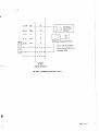
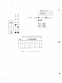
160
System Configuration
160.1
To
Determine
Required Equipment
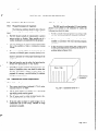
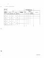
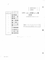
1.
Determine how many electronic key telephones are required in the system. Refer to Table A if the number
of keysets are 8 or less. Refer to Table B if the number
of keysets are more than 8.
2.
Determine how many CO/PBX lines are required. The
result will tell you which line of the selected table to
use. See Table 160-l.
Required Quantities
Table 160-l
TABLE
A:
Note:
160.2
1.
1
1
I
Power Failure hansfer
To Determine
Optional
1
t
/
I
I
4-6
1
/
l-3
KSI-S
SWMS
OCIS/MFIS
/
I
TABLE B: Tota! Number of Keysets is 9 - 16
Total Number of Keysets is 1 - 8
COIPBX LINES
of KThls
2
I
1 CO/PBX LINES
/
I
I
l-3
I
1
is provided in ES-6-I
1 svw-s
DCIWMFIS
4-6
i
2
2
2
I
KSIS
.I
2
I
2
I
KSU for CO/PBX Lines 1 and 2.
Equipment
Required KTUs for options are:
Table 160-2
OPTION
AHR-S
1
Door Phone
DPH-S
1
External
PBS-S
Automatic
t- _-_--_+
Note:
Hold
Paging
Release
1
!
I
BLF Console
PBS-S
1
Security
PBS-S
1
Alarm
2 Door Phones
I
2 BLF Consoles
One PBS-S KTU provides circuitsfor external paging. 2 BLF consoles,
2 security alarm circuits.
and
6
Page 100-7
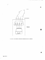
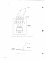
/---
CQlP0X
123
\
456
---_------__
-I
I
I
I
1
I
I
I
I
I
I
I
I
I
I
I
I
1
2
SWM 2
DOOR
DOOR
PHONE
PHONE
i I I
I
1
2
---I-l
EXT.
SPEAKER
I
I
SECURITY
CONTROL
EQUIPMENT
[ 13
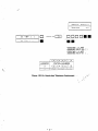
installed in ES&l
Fig. 160-l
Page 100-8
PS-6-!
KSU
System Block Diagram
200
SECTION
HARDWARE
INSTALLATION
CONTENTS
Page
210
installation
of the Key Service Unit
210.1
Wall Mounting
210.2
Floor Mounting
. . . . . . . . . . . . . . . . . . .
200-1
the KSU
the KSU
220
Connecting
and Testing the Power Supply
. . . . . . . . . . . . . .
200-z
230
Installation
of KTUs . . . . . . . . . . . . . . . . . . . . . . . . . . . . . . .
200-3
f
240
250
260
230.1
General
230.2
Installing
Basic KTUs
230.3
Installing
Common
KTUs
230.4
Installing
Optional
KTUs
230 5
Volume
MDF
Information
Controls
Installation
240.1
CO/PBX
240.2
Station
. . . . . .. . . . .. . . . . . . . . . . . . . . . . . . . . .
Cabling Connection
Installing Station
Equipment
250.1
ET-6-l
Installation
250.2
EB-6-1
Installation
250 3
DP-6-l
installation
installing Options
. .. . . . . . . . . . . . . . . . .. . .. .
200-g
. . . . . . . . . . . . . . . . . . . . . . . . . . . . . . . . . 200-14
260.1
Music On Hold
260.2
External
Paging Speaker
260.3
External
Background
260.4
External
Tone
260.5
External
Paging Amplifier
External
Background
260.6
ZOO-6
Connection
Music when PBS-S
KTU
is Used
Ringer
Music when
is Used
260.7
Power Failure
Telephones
260.8
Security
Control
260.9
External
Amplifier
Equipment
Control
External
Amplifier
SECTION
210
Installation
210.1
Wall Mounting
1.
of the Key Service
200
HARDWARE
210.2
Unit
the KSU
The ES -6-l
KSU is supplied with a wall mounting
bracket. The bracket should be mounted on a backboard secured in a manner capable of holding the
weight of the KSU. With the mounting tabs of the
bracket facing upward, install appropriate screws into
the 6 holes of the bracket. Loosen the securing screw
located in the upper right position of the bracket.
2.
Align the mounting slots of the KSU with the mounting tabs of the bracket, and push down to seat the
KSU securely.
3.
Remove the front cover of the KSU, and locate and
tighten the securing .screw through the hole provided
above the J 1 connector.
..
SECURING
SCREW
INSTALLATION
Floor Mounting
the KSU
1.
The same bracket that is provided for wall mounting
can also be used to anchor a floor mounted KSU. Set
the bracket on a level surface with the 6 screw holes
down and the securing screw facing up and the floor
mounting slot to the right.
2.
Loosen the securing screw located
position of the bracket.
3.
Engage the mounting tabs on the bracket into the slots
on the bottom of the KSU and push forward to seat
the KSU securely.
4.
in the rear right
Locate and tighten the securing screw through the hold
provided on the bottom panel of the KSU.
\
\
0
I 2(
0
-0
FLOOR
Fig. 210-l
Front
MOUNTING
View of hbunting
SLOT
Bracket
Page
’
220
Connecting
Note 1:
Note 2:
1.
2.
and Testing the Power Supply
+41v
Verify that the AC outlet is supplying 11% AC
and provides good conduit ground. If there is a
problem with the AC voltage, have it corrected.
If there is no conduit ground, provide alternate
ground as explained in Section 120, “Grounding
Requirements”, of this manual.
I 03
I e3
,
Fig. 220-2
3.
of g-pin Connector
of PS-6-l
Set PSU Power Switch to Off Position
Note:
I
Verify that step 3 has been completed before proceeding. Verify that PS-6-I
Power Indicator Lamp
is off:
4.
Connect the 9-pin connectorended
Supply Unit to the 9-pin connector
that the looking tabs are engaged.
5.
Turn the PSU Power Switch on. DC voltage (under
load) can now be read on the TBl terminal block
located on the left side of KSU.
Page 200-2
cable of the Power
of the KSU. Ensure
I
cl3
e3
View
+12G
+5G
+12G
+5G
I
of TBI
Terminal
Block
When measuring DC voltages, note that each voltage has
its own reference ground.
The Power Supply Switch must be set in the Offposition before proceeding with installation.
Note:
View
+24G
H
I
+5v
+41G
I@I
6.
Front
+12v
I@/
Remove the 9-pin connectorended
cable of the power
supply from the connector of the KSU.
Fig. 220-I
1
t
Before proceeding, ensure that the PS-6-I
Power
Cord is unplugged.
The PS-6-I
Power Switch
should be off, and its power indicator lamps should
Plug the AC cord of the power supply into an AC
outlet. Set PSU Power switch to on position. The PSU
Power Indicator Lamp should light. Use a voltmeter,
to the figure below:
7
+24V
Veriyy that Step 6 has been completed before proceeding. Verify that PS-6-i
Power indicator Lampis oft
1I
@)
F--
230
Installation
Note:
The following KTUs
with power on:
CPU-S
CLK-S
SWM-S
-_.
230.1
1.
General
cannot
be inserted
KSI-S
DCI-S
MFI-S
_... .._ .._
or removed
DPH-S
PBS-S
AHR-S
_._..-
3.
.__J
The KTUs specified directly above cannot be inserted
or removed -with power on. It is recommended
that
power be OFF during installation and during maintenance unless this will seriously inconvenience the user.
This will prevent accidental damage to equipment.
KTUs are provided with a guide slot to prevent misinstallation. KTU connectors are provided with a guide
key. These guide keys must not be removed.
T
1
Installing
Basic MTUs
DC1 -S and MFI -S KTUs
When installing DCI-S and MFI-S KTUs there may
be more KTU circuits installed (since there are 3 per
KTU) then will actually be used. Any non-used circuits
should be programmed as “not installed” when programming for CO/PBX line assignment. See Section
of this manual for instructions
300 “Programming”
on programming
CO/PBX line assignment. This will
avoid confusion when attempts to access unconnected
CO/PBX lines are made. The DSI-S or MFI-S in the
first designated KTU position (DCI/MFI 1) serve CO/
PBX lines 1 through 3. A DCI-S or MFI-S in the
second designated KTU position (DCI/MFI 2) serve
CO/PBX lines 4 through 6. Refer to figure 230-2 for
KTU positions in the Key Service Unit. See AHR-S
KTU in Section 230 for information’on
wiring change
for providing Automatic Hold Release feature when
AHR-S KTU is installed.
2.
SWM-SKTU
An SWM -S KTU must always be installed in SWM 1.
An SWM-S KTU must be installed in SWM2 when
either stations 9 - 16 and/or CO/PBX lines 4 - 6 are
to be connected.
Information
The KTUs used in the Electra-616
system make extensive use of CMOS technology. Care must be taken
to avoid static discharge when handling these KTUs.
230.2
are Smm by 20mm and are rated OSA 125V: one
fuse for each keyset. The fuse provides protection on
the data transmission pairs (DT and DR). When a fuse
must be replaced refer to Section 140, “Fuse Replacement” of this manual.
of KTUs
Table 230-I
Installing
SWM -S
SWMl
SWM2
230.3
I.
KTUs
WHEN
SLOT
/
SWM-S
/
For Stations
1 - 8 and CO/PEX
For Stations
9 -
Installing
&mmon
16 and/co
lines 1 - 3.
CO/PBX
lines 4 - 6.
KTUs
CPU-S STU
Before programming the Network Plan Memory (NPM),
ensure that the SW1 switch located on the CPU-S
KTU is set to the ON position. This will provide
battery back-up for the NPM, speed dial, and last
number dialed memories when power is lost to the
KSU. If there is a power failure and switch is left in
the OFF position, the system will lose the contents of
memory and return to the Resident System Program.
For a description of the Resident System Program see
Section 300 “Programming”.
When the CPU-S KTU
is removed for long-term storage, set the SW1 switch
to the OFF position. This will prevent the battery from
constantly discharging until it is no longer capable of
holding a charge. The battery, when fully charged,
will protect the memory for approximately
60 days.
back-up
failure.
KS1 -S KTU
to the Electra-616
ON-
There are two designated KS1 KTU positions within
the Key Service Unit. The KS1 -S in the first position
(KS1 1) serves stations 1 through 8, while a KSI-S in
the second position (KS1 2) serves stations 9 through
16. Located on each KS!-S KTU are 8 fuses which
--
system
during a power
OFF
SW1
Fig. 230-l
CPU-S Switch
for Volatile
Memory
Page 290-3
I
On the CPU-S KTU is a momentary switch for system
reset. Depressing the reset switch causes any program
changes to enter the working program and interrupts
all system operation in progress.
2.
D--M
CLK-S KTU
SW1
When DCI-S KTU(s) is installed ensure the switches
SW1 and SW2 on the CLK-S KTU are set to appropriate positions. Refer to Table 230-2 below. The
switch settings are subject to the dialing specifications
of the CO or PBX. The switches have been set by the
manufacturer
at 1Opps dial speed and at 39% make
ratio.
Table 230-2
Rotary
Dial Pulse Signalling
Switch
Settings
Fig. 230-2
Door Phone/Monitor
Phone
Select Switches
Dial Speed SW1
230.4
1.
installing
Optional
;
:z;
/
3.
KTU
Located on each DCI-S and MFI-S KTUs are three
straps (one for each line circuit) that should be
removed when AHR-S KTU is installed for Automatic Hold Release option. When AHR-S KTU is not
installed, the straps should be left connected to the
solder terminals. Refer to Figure 230-3 for terminal
designations. The AHR-S will release a CO/PBX line
which is on hold when the outside party abandons the
call. A timed disconnect signal of more than 150 milliseconds must be provided from the CO or PBX to
enable this option (the AIIR-S does not recognize a
reversal of polarity). The AHR-S KTU serves up to
6 CO/PBX lines and is installed in ES-6-l
KSU.
Remove the straps when AHR-S KTrJ is installed.
KTUs
PBS-S KTU
Install PBS-S KTU in ES-6-1
KSU when External
Paging,Busy
Lamp Field and/or Security options are
required. Refer to Section 250.2 “EB-6-1
Installation” for BLF connection.
When installing External
Paging and/or Security options, see Section 260, Installing Options”.
7__
AHR-S
DPH-S KTU
When a DPH-S KTU is installed in the ES-6-l
KSU,
two DP-6-1
can be used as Door Phone or Monitor
Phone separately.
When Door Phone 1 is required as a Door Phone, set
the SW1 to the “D” position on the DPH-S KTU.
(In the case of Door Phone 2, set the SW3 to the
“D” position.)
When Door Phone 1 is required as a Monitor Phone,
set the SW1 to the “M” position on the DPH-S KTU.
(In the case of Door Phone 2, set the SW3 to the “M”
position.) and remove the straps Sl and S2 on the
DPH-S KTU. (In the case of Door Phone 2, remove
the straps S3 and S4). Then the voice from Key Set
will be cut off when Door Phone is accessed, and the
voice from DP-6-l
is more amplified compared with
being used as Door Phone.
/
I
DCI-S
1
or
MFI-S
1
Fig. 230-3
Page 200-4
1
DCI-S
Line Circuit
3
Line Circuit
6
and MFI-S
AHR
Straps
230.5
1.
2.
Volume
All volumes are pre-adjusted
Refer to Table 230-3.
Controls
AlI tones from the built-ii speaker in a keyset are
controlled at the keyset by adjusting the volume dial
located at the front of the keyset.
Table 230-3
by the manufacturer.
CLK Volume
Controls
System wide CO/PBX ring (station id!e) and intercom
all call and zone paging are controlled by adjusting
volume controls on the CLK-S KTU. Tone level is
increased by turning the volume control clockwise.
.ii,
-
L
I
5A
FUSE
OFF
POWER
---K
-
-
n
-
-
-...-c2
-
-
11
J2
N
TBl
z
a
3
8
8
2
;’
z
2
Pl
J
N
E
2
0
:
5
L
u
-
I
4
-
J
J
-
-
Fig. 2304
ES-6-l
-
-
KSU Card Layout
Page 200-5
- -
240
MDF
240.1
CO/PBX
1.
+ 2.
3.
Installation
Connection
The FCC approved USOC number for 50 position
miniature ribbon jack for connection
of CO lines is
IU21X. The CO lines are to be connected in sequence
consecutively within this jack.
Use of 66BSO or 66M50 quick-connect type blocks is
recommended
for ease of trouble location and correction. Use of bridging clips allows easy separation of
the system to determine cause of trouble.
-.
k&+.
The following Table 240-1 gives complete information
on 50 position connector pin number, lead function,
running cable color, circuit designation,
associated
DCI/MFI slot:
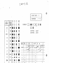
240.2
1.
___-___-_
Station Cabling Connection
The following tables give complete information
on
KSU, cable, 50 position connection pin number, running cable color, lead designation, station cable color,
intercom number assignment, KSI-S slot assignment,
etc. for all stations. Refer to Table 240-2 and 240-3.
Table 240-l
CO/PBX
Connection
Pl Connector
CABLE
FUNCTION
PIN
Information
& Cable ES-6-l
COLOR
26
1T
WH-BL
1
1R
BL-WH
KSU
CiRCIJlT
CO/PBX
1
2T
2R
WH-OR
CO/PBX
2
28
3T
WH-GN
CO/PBX
3
3R
GN-WH
29
4
4T
WH-BR
4R
BR-WH
27
,
OR-WH
5T
WH -SL
5R
SL-WH
31
6T
6
6Fi
SLOT
2
DCI/MFI
1
3
CO/PBX
4
CO/PBX
5
DCI/.MF12
The rest of PI Cable is spare and is not used.
CO/PBX
Connection:
I.
FCC approved
2.
Connector-ended
cable for CO/PBX lines to plug info ES-6-I
Jack (Female) 50 position miniature ribbon connector.
connector
USOC code is RJ21X.
KSU requires
Page 200-6
.%
Table 240-2
Station
Connection
Jl - 52 Connectors
PIN
RUNNING
STATION
CABLE
CABLE
LEADS
KEY
SET
Information
and Cables ES-6-1
SLOT
CABLE
Jl
KSU
SLOT
CABLE
92
26
WH-EL
GN
VT
(See Note)
(See Note)
1
BL-WH
RD
VR
STA.
STA.
27
WH-OR
YL
DT
2
OR-WH
BK
DR
28
WH-GN
GN
VT
1
9
(ATT)
(ATT)
I----
3
GN-WH
RD
VR
STA.
29
WH-BR
YL
DT
2
4
BR-WH
BK
DR
30
WH-SL
GN
VT
5
SL-WH
RD
VR
STA.
31
RD-BL
YL
DT
3
17
6
BL-RD
BK
DR
32
RD-OR
GN
VT
7
OR-RD
RD
VR
STA.
STA.
33
RD-GN
YL
DT
4
8
GN-RD
BK
DR
KSI
34
RD-BR
GN
VT
1
9
BR-RD
RD
VR
STA.
35
RD-SL
YL
DT
5
10
SL-RD
BK
DR
36
BK-BL
GN
VT
11
BL-BK
RD
VR
STA.
37
BK-OR
YL
DT
6
12
OR-BK
BK
DR
38
BK-GN
GN
VT
13
GN-BK
RD
VR
STA.
STA.
39
BK-BR
YL
DT
7
15
14
BR-BK
BK
DR
40
BK-SL
GN
VT
15
SL-BK
RD
VR
STA.
STA.
41
YL-BL
YL
DT
8
16
16
BL-YL
BK
DR
P
Note:
STA.
10
STA.
12
KS!
Two stations in rhe sysrem can be assigned as attendant srarions. Stations 1 and 9 are initialIy assigned
these positions. Sration 1 must be insralled for programming purposes.
Page 200-7
Table 240-3
26
1T
WH-BL
LIN
1
1R
BL-WH
1
27
2T
WH-OR
LIN
2
2R
OR-WH
2
28
3T
WH-GN
LIN
3
3R
GN-WH
3
29
4T
WH-BR
LIN
4
4R
BR-WH
4
5T
WH-SL
LIN
5R
-6T
SL-WH
5
_-_-__j.-. ..-.._
RD-BL
LIN
6R
1VT
1
1VR
WH-BL
BL-WH
TEL
27
1DT
WH-OR
1
2
1DR
OR-WH
28
2VT
WH-GN
3
2VR
GN-WH
TEL
29
2DT
WH-BR
2
4
2DR
BR-WH
30
3VT
WH-SL
5
3VR
SL-WH
TEL
31
3DT
RD-BL
3
6
3DR
BL-RD
32
RD-OR
j
32
4VT
RD-OR
7
OR-RD
/
7
4VR
OR-RD
TEL
33
4DT
RD-GN
4
8
4DR
GN-RD
12
42
6
26
1
35
List
52
BL-RD
9
1
Running
Jl
Pl
30
Connector
34
5VT
RD-BR
j
/
BR-RD
1
9
5VR
BR-RD
TEL
I
/
RD-SL
/
35
5DT
RD-SL
5
IO
-- 5DR
SL-RD
36
6VT
BK-BL
11
6VR
BL-BK
TEL
37
6DT
BK-OR
6
12
6DR
OR-BK
38
7VT
BK-GN
13
7VR
GN-BK
39
7DT
BK-BR
39
15DT,
14
7DR
BR-BK
14
15DR
/
1
I
j
I
OR-BK
YL-OR
i
j
40
16’0
1
15
’ 16VR
I;
SL-BK
i
TEL
41
8DT
YL-BL
8
41
! 16DT
I
YL-BL
/
16
16
8DR
BL-YL
BL-YL
/
42
1BLT
YL-OR
YL-OR
j
17
-43
1BLR
OR-YL
-.._- _..._ __-_-_-_
1 DVT
YL-GN
19
BR-YL
i
45
YL-SL
19
-45
MOH
/
22
OR-VI
_-.
VI -GN
47
23
49
VI -OR
e&._/_.___-.
24
-50
25
Page 200-8
BR-VI
____-.
v, _SL
+
I
SL-VI
-_-
SL-YL
SKR
VI-BL
21
SKRG
.._-_-.
BGM
BL-VI
22
I
:
BGMG
_.
.-..__...
ERA
1 16DR
‘6!--_.<
42
/ 2BL.T
BLF
1
-.--. -..-.
..- .
DOOR
j
‘7 _I.?!%
i. _.ck!_L...
YL-GN
/
PHONE
j
1
MOH
EXT.
SPEAKER
--_-.----.
-.
VI -OR
OR-VI
__._._.-_- .._.
VI-GN
BGM
--.-_--_
EXT. RINGER
ERB
GN-VI
CONTROL
23
VI-BR
POWER
49
/
24
--.
50
1PFR
_.
_.
2PFT
BR-VI
24
’
VI-SL
FAILURE
1
__..-... ._ _--.
POWER
25
-
2PER
SC-VI
FAILURE
2
5o
25
I
/
-BLF
2
i. .-.--.----.--.
/ DOOR PHONE
SECURITY
1PFT
23
z__. _-.
BR-YL
---YL-SL
MOHG
48
/
+-
1SEG
GN-YL
YL-BR
20
-_
46
47
48
15
/
TEL
1 DVR
--_
1SE
BL-VI
TEL
!
BK-SL
18
._ssc-yL+.VI-BL
/
BK-ER
j
SL-BK
44
21
GN-BK
8VT
i
46
1 15VR
8VR
/
_._
13
15
YL-BR
20
__~
BK-GN
40
GN-YL
/
I 15VT
BR-SK
-LBK-SL
44
18
TEL
38
GN-VI
/
VI-BR
/
j
1
/
BR-VI
/
VI-SL
/
I
SL-VI
~
250
IrkaIling
250.1
ET-6-l
Station
Equipment
installation
The ET-6-l
is a fully-modular electronic key telephone set. Each keyset requires 2pair cabling to the Main
Distribution
Frame (MDF). The maximum cable length is
700 ft. using standard 24 AWG cable and 1,150 ft. using
standard 22 AWG cable. Refer to Section 140, “Cabling
Requirements”,
of this manual. For keyset connection,
see Figures 250-I and 2.50-2 and Table 240-2.
STATION
CABLE
DR (BK)
TO KSU
VR
FIDI
VT
(GN)
’
_
J
a
MODULAR
TERMINAL
DR
ET-6-l
Fig. 250-l
Simplified Schematic -
VR
VT
DT
TELEPHONE
ET-6-7
Telephone Connection
Page 200-9
_..._,.^
.._______.....__.....
-- .-.._ . -. ..__.
-..
TO KSU
CABLE
r
MODULAR
TERMINAL
J
________--__
Fig. 250-2 View of Modular
Page 200-10
?
Terminal
for Connection
of ET-$-l
Telephone
..-
-L,.-L-
”
&
2502
EB-6-l
installation
The EB-6 -1 is a modular
electronic busy lamp
field. Each unit is provided with a 9V DC 03A power
supply for LED illumination.
The power supply is to be
plugged into a standard 117V AC outlet. Each BLF requires
1 -pair cabling to the main distribution frame (MDF).
The maximum cable length is 700 ft. using standard 24
AWG cable and 1,150 ft. using standard 22 AWG cable.
Refer to Section 140, “Cabling Requirements”,
of this
manual. For BLF connection,
see Figures 250-3, 2504
and 250-S and Table 240-3.
RUNNING
CABLE
BLR (BK)
TO KSU
BLT (Y L)
DR
DT
EB-6-1
Fig.
2503
Simplified
Schematic
-
EB-6-1
BLF
BLF Connection
Page 200-il
____..__
_._--
. . . ....- ._.--. _- .-_ ..I ._._
_-__-l-._-~-.C_~“~-~~
‘xL..?Au.-..
TO KSU
BLFCABLE
I
I
MODULAR
TERMINAL
I
I
L _____------Fig. 2504
View
of Modular
Terminal
-I
for Connection
of EB-6-1
EB-6-1
/
TO POWER
SUPPLY
Fig. 250-5
Page 200-12
Power Supply
Connection
BLF
BLF
. . . . __.~,
250.3
DP-6-1
Installation
The DP-6-1
is a Door/Monitor
phone unit. Each
door phone requires 1 pair cabling to the Main Distribution
Frame (MDF). The maximum cable length is 700 ft. using
standard 24 AWG cable and 1,150 ft. using standard 22
AWG cable. Refer to Section 140, “Cabling Requirements”
of this manual.
To prepare the door phone for wall mounting losen the set
screw and remove the door phone unit from the mounting
plate. Use the two screws provided or other appropriate
fastners to fiiy
connect to wall surface. For door phone
cable connection, see Figure 2506 and Table 240-3. Refer
to Section 340, ‘Programming
Sheets” for Door Phone
assignment.
SCREW
SLOT
POSITIONS
TO
Fig. 250-6
Rear View
of DP-6-l
Door Phone
Page 2m-13
‘-_
260
installing
Options
260.1
Music On Hold
2605
Provision has been made to allow connection of a
locally provided external music source to provide MusicOn-Hold for held CO/PBX calls. Connection of the Music
Source is made at the Jl Block of the Main Distribution
Frame (MDF). The output signal level should be approximately 1 milliwatt with 8 ohms impedance. See Figure
260.3 and Table 240.3 for connection information to MDF .
260.2
Paging Speaker
External
Background
Music when PBS-S
External
ON
OFF
Tone
ON
-
-
OFF
SW4
SW3
Ringer
Provision has been made to allow connection
of
locally provided External Tone Ringer to supply common
audible on all incoming CO/PBX calls. For this purpose a
relay contact is prepared on the CLK-S KTlJ. which
provides an interrupted
closure (1 SEC. on/ 1 SEC. off)
during the CO/PBX Ring Cycle. The signal of the tone
ringer can be controlled
by a locally provided control
switch. See Figure 260-3 and Table 240-3 for connection
information to MDF.
Page 200-14
c-.-..
KTU
When a PBS-S KTU is installed, an external locallyprovided music source can be used to supply background
music over the External Paging System. The recommended
output of the music source is l-watt with 600 ohms impedance. When external paging is accessed music is cut off
from the paging speaker. Connection
is made on the Jl
block of the MDF. See Figure 260-3 and Table 240-3 for
connection information to MDF.
External
Music when External
is Used
To provide for background music with an external
amplifier installed, set the SW4 switch io the “ON” position and the SW3 switch to the “OFF” position on the
PBS-S KTU. When background music is not required set
the SW3 switch to the “ON” position and the SW4 switch
to the “OFF” position. Music will be cut off from the .
paging speakers when external paging is accessed. The
output level and impedance of the music source should
match the input level and impedance of the external
amplifier. See Figure 2604 and Table 240-3 for connection information to the MDF.
is Used
260.4
Background
Amplifier
When a PBS-S KTU is installed in the ES -6 - 1 KSU,
external paging with meet-me answer can be provided. The
PBS-S KTU contains a 1 -watt Amplifier and Control
Circuit for one-zone paging (when a l-watt amplifier is
insufficient,
see Section 260.5.) The External Speaker
should be locally-supplied in correspondence to the output
impedance
of 600 ohms. The Volume Control (VRl),
located on the PBS-S, provides a way to increase or decrease the output signal of the amplifier to the speakers.
To adjust output signal, turn VR1 clockwise to increase
signal, and counterclockwise
to lower signal. An LED is
provided on PBS-S KTU to indicate when paging is being
used. When an External Page is answered (meet-me-answer),
the PBS-S is released to allow access for another page.
See Figure 2 60-3 and Table 240-3 for connection information to MDF.
260.3
Paging Amplifier
The PBS-S
KTU contains a l-watt Amplifier and
control circuit for external paging. For applications where
1 -watt is insufficient, an external amplifier may be used.
Provision has been made to allow connection of a locallyprovided amplifier to the MDF for this purpose. The PBS-S
KTU is required when an external amplifier is used. See
Figure 2604 and Table 240-3 for connection information
to the MDF.
260.6
External
External
Fig. 260-I
260-7
Power
Failure
PBS-S Switches
for BGM
Telephones
ET-6-l
Ke:J Telephone Sets cannot be used to
originate
or answer calls during a commercial power
failure. Locally-provided
single line telephone sets can be
installed for this purpose. The KSU provides automatic
power failure for CO/PBX lines 1 and 2. No optional KTU
is required. Connection
of the Single Line Telephones is
made at the Jl block of the MDF. Single Line Telephones
with appropriate dials (rotary or DTMF) should be installed
if the capability of dialing out during a power outage is
desired. See Figtire 260-3 and Table 240-3 for connection
information to MDF.
26043
Security
Control
Equipment
260.9
Provision has been made to allow connection of a
locally-provided
security control system. For this purpose
the PBS-S KTU contains 2 individual control circuits that,
when activiated, provide an audible alarm through all idle
keyset speakers and a visual alarm on each keyset display.
Each security circuit can be activiated by means of an
external make (closed) or break (open) contact. The SW1
switch on the PBS-S KTU is used to set the desired break
or make detection for security circuit one and the SW2
switch performs the same function for security circuit two.
For connection information
to the MDF see Figure 260-3
and 260.4 and Table 240-3.
1M -
-
18
piT=q
-
Amplifier
Control
A set of dry contacts is provided on the PBS-S
KTU, which can be used to control an auxiliary relay for
External Paging. Although this option is not required when
an external amplifier is used, it may be desired in some
applications. When an external page is activiated the EAS
and EAM contacts are closed for the duration of the page.
In the idle condition the closure is made between the EAS
and EAB contacts. See Figure 2604 and Table 240-3 for
connection information to the MDF.
20
p7i-l
SW2
SW1
Fig. 260-2
2M -
External
PBS-S Security
Control
Switches
Page 200 - 15
_.
Y L-BR
44
1SE
-oo-oo-
SECURITY
1
ACTIVATION
BR-Y L
1SEG
-o&a-
YLSL
MOH
--Qc2Lo-
SL-YL
MOHG
VI-BL
SKR
CONTACT
---p&&i
-o&o-
EXTERNAL
PAGING
BL-VI
SKRG
-o&o-
VI-OR
BGM
-4&o-
OR-VI
BGMG
-oEoo-
SPEAKERS
(600.52)
CLK-S
-ocPoo-
-oEoo-o&*
POWER
FAILURE
CONNECTION
-o&c
VI-SL
2PFT
FOR CO/PBX
-o&*
POWER
25
FOR COIPBX
:
BLOCK
OF MDF
(668-50
Fig. 260-3
..-
Page 200-16
FAILURE
CONNECTION
-ac--Oo-
Jl
1
OR 66M-50)
Connection
of Optional
Features
2
_.__.
-.-
..
YL-BR
2SE
00%
IPBS-S
-
BR-YL
2SEG
YL-SL
EA
SL-YL
EAG
VI-BL
EAB
BL-VI
EAS
00%
00%
t
O&
AGING
RELAY
t
VI -OR
AMPLIFIER
oa
EAM
CONTACT
(NON-OPERATED)
00%
FOR THE
DURATION
EXTERNAL
PAGE
SHOWN
IS OPERATED
OF AN
Oc%
OR-VI
00%
h
J2 BLOCK
OF MDF
(668-50
Fig. 2604
OR 66M-50)
Connection
of Optional
Features
Page 200-17
_-
SECTiON
300
CONTENTS
310
Explanation
320
Programming
,
330
.
.
Operations
300-l
. . . . . . . . . . . . . .. . . . . . .. . .. . .
300-3
Going Off-Line
320.2
Selecting
a Memory
Block
320.3
Selecting
Addresses
Using the Dial Pad
320.4
Entering
Data
320.5
Use of Function
320.8
Going On-Line
320.7
Resetting
320.8
To Return
Job
from
. . . . . . . . . . . . . . . . . . . . . . . .
320.1
330.1
340
of Programming
Keyset
Buttons
1
in Programming
System to Change Contents
System to Resident
System
of NPM
Program
. . . . . . . . . . . . . . . . . . . _. . . . . . . . . . I .
Specifications
Instructions
for Completing
300-6
Job Specification
Programming Sheets . . . . . . . . . . . . . . . . . . . . . . . . . . . . . . . 300-12
340.1
Programming
Details
3402
Memory
Block 1
340.3
Memory
Block 2
340.4
Memory
Block 3
340.5
Memory
Block 4
SECTION
310
Explanation
300
of Programming
2.
1. The Electra-616
Electronic Key Telephone System
comes nrovided with a Resident System Program in PROM
(Programmable
Read Only Memory). When the system is
powered this Resident System Program is duplicated in
RAM (Random Access Memory) and becomes the Network
Plan Memory (NPM). The NPM is the program the system
actually utilizes. This NPM will norrna.lly be supplemented
by progr arnrning performed at each installation to provide
the system program desired for the individual site. The
additional programming is entered into RAM which is volatile, but which has been provided a battery to retain
program during power outage.
I
battery
provided
on the CPU-S
PROGRAMMING
KTU
Keyset 1 must be installed to allow System Prograrnming. NO other station can program system data. The
programming procedure includes the foilowing steps:
1.
Completion
of job specification
2.
Completion
of programming
3.
Taking keyset 1 “Off-line”
4.
Selecting a memory block (using DSS buttons),
thus selecting the general area of the memory to
be modified.
5.
Selecting addresses via the dial pad.
6.
Entering data via CO/PBX button
ton and DND button.
7.
Displaying data, clearing data, changing address
(plus or minus 1 address increment) and writing
datausing the Add-On, Last NBR, Hold and Speed
Dial buttons.
8.
Repeat steps 4 th_ru 7 until all desired data has been
written into memory.
9.
Return keyset 1 to “on-line”
is switched
lost with the firsr loss of Power to rhe KSCJ.
10.
work sheets.
! -6, MIC but-
mode.
Put the program into the working Network Plan
Memory. This function will occur automatically
when the entire system is idle. An alternate
method is to depress the reset button on the
CPU-S KTU; this will interrupt service. Testing
of the new program can then be performed.
Page 300-l
_-’
The contents of the Resident System Program (default
value) are given below in the following Table 310.1:
Table 310.1
Resident
System
Program
Contents
DEFAULT
FUNCTION
Time
is 0.4 sec.
Pause Timing
Time
is 1.0 sec.
Paging Timeout
Time
is 60 sec.
Hold Recall
Time
is 60 sec.
Button Timing
Recall
System
Refresh
Night
Ringing Assignment
Stations
1 and 9 ring for all CO/PBX
Stations
7 and 9 will ring
Door Phone Assignment
Door Phone not assigned
Door Phone Chime Assignment
Stations
1 and 9 chime
Off Hook
Stations
1 and 9 ring
Prime
Ringing Assignment
No stations
Paging Zone Assignment
Attendant
Station
Line Pick-Up
Prime Line Pick-Up
1 and 9 are attendant
Assignment
stations
Not assigned
Assignment
for incoming
in any zone
Calls
No prime line on incoming
Prime Line Assignment
No private
CO/PBX
Line Scan Assignment
Scan goes from CO/PBX
CO/PBX
Line Assignment
All lines are CO
PBX access code “9”
CO/PBX
All lines are group A
Group
Assignment
Digit Rejection
is assigned
“1” + Dialing
Assignment
Assignment
No digits rejected
Speed Dial Toll Override
Assignment
Toll restriction
Toll Restriction
Table Assignment
No 3-digit
Override
line 2 to 1
All stations are class 0 (non-restricted)
Class Assignment
“1” + Dialing
calls
lines
PBX Access Code Assignment
Station
Page 300-2
Ringing Assignment
Mode CO/PBX
Internal
/....\
Based on no change in status
Basis
Day Mode CO/PBX
VALUE
is overriden
codes in table
lines
320
2.
Programing Operations
Going Off-Line
320.1
from
Keyset
1
ON/OFF
is lit
Keyset 1 is “Off-Line”
Selecting
320.2
1.
a Memory
DATA
BUTTONS
Block
To select a memory block, depress the appropriate DSS
button on Keyset 1 while in off-line status. To simplify
programming
of system data, use the programmir %
overlays provided with each ES-6-1
KSU.
Note:
Taking Keyset I off-line removes that keyset from
service. The rest of the Electra-616 system continues
to work. If Station I is the Attendant Keyset. it may
be desirable to enter night mode to provide ringing
while keyset I is off-line. This depends on the installation
320.3
Selecting
Addresses
Entering
Data
To enter data the CO/PBX, MIC and DND buttons are
used. The LED’s associated with each of these buttons
show the status of the datum corresponding to those
buttons. When an address is in “clear” mode, no LED
is lit.
Buttons
1 - 8 are used to Enter Data
Please note that buttons 7 and 8 are the MIC and DND
buttons. In the programming instructions, they will be
referred to as buttons 7 and 8.
320.5
Use of Function
Buttons
in Programming
Last NBR Button
The Last NBR button is used to perform a clear. When
a data button is depressed and its LED is lit depressing
the data button will change this status; the Last NBR
button will clear the entire address (up to 8 data
buttons) which can then be reprogrammed. The Last
NRB button will only clear that single address except
when Keyset 1 is engaged in programming Memory
Using the Dial Pad
After selecting the memory block, the first address
desired must be entered by using the dial pad. After dialing
* 1 or 2 digits (dialing a 0 first is not required for addresses
numbering less than 10) the display will show the address
selected. If programming deals with consecutive addresses
there is no need to redial as addresses are automatically increased by 1 after writing data into memory. Manual operation of function buttons also allows increasing or decreasing
the address by increments of 1. Redialing to change an
address is possible at anytime.
320.4
Fig. 320-l
1.
I
1.
The method of entry using the CO/PBX, MIC and DND
vary from address to address. Sometimes they are used
singly as for a yes/no choice, sometimes in groups to
write numbers in binary. The programming sheets for
the different features show how to enter data for each
individual address under consideration.
Block
2.
5.
HOLD or ADD-ON button depressed once after
dialing an address will cause the contents of that address
to be displayed: immediately after dialing an address
one of these buttons must be depressed. Each subsequent depression of the HOLD button will decrease
the address by 1 and display the contents of that new
address. Each subsequent depression of the ADD-ON
button will increase the address by 1 and display the
contents of that new address. Only the first use of
either button after dialing an address will display that
address without
changing it.
The
Page 300-3
3.
i
t
.
j
Speed Dial Button
‘.
The Speed Dial button is used to write the contents of
the address as it is currently displayed into the progr~arnming RAM: all previous operations will not result
in any program change until this step is completed. In
this memory block, all addresses can be cleared and
:c ritten to initialize the RAM memories and return the
system to the Resident System Program.
320.6
1.
!
.._
-
depress
m
-
depress
1ON/OFF 1
Keyset 1 is returned to on-line mode. The Electra-616
system will not return to the Resident System Program until either the entire system is idle or the reset
button on the CPU-S KTU is depressed.
Programming
Going On-Line
Depress ON/OFF button (Restore the handset) to
return keyset 1 to On-Line mode. The display of
keyset 1 will show(dlo1
until program is accepted
into the working NPM memory. Other displays will
temporarily
override this display, but it will return
whenever the display is otherwise idle until the system
working program changes.
:’
:a:
Resetting
320.7
Systemto
Change Contents
.
of NPM
It is possible to reset the system by depressing Reset
button on the CPU-S KTU. This may not be necessary
because the system memory will be rewritten when the
entire system is idle. While this may cause delay, it
does not drop all service in progress as does the reset.
1.
2.
-
depress [xl
-
depress [ON/OFF/
-
depress
-
depress
-
depress
System
to Resident
System
2.
-
..^
Memory Block 5 can be used to initialize all system
NPM memories at once when disired. Use of this
memory block will return the system to the Resident
System Program (in PROM).
Procedure
Program.
to
Return
System to the Resident
with keyset 1 Off-Line
Display Shows
-
depress [ass]
-
depress /7/
-
depress m
-
depress data button
5.
depress 1ADD-ON
/
To Decrease 1 Address
-
7.
or 1 HOLD
depress 1-1
To Increase i Address
depress 1HOLD
1
To Clear An Address
-
i
depress (LAST]
Write An Address
1, 3, 5 and 7
- depress j
9.
To Go On-Line
-
Page 300-4
dial I or 2 digit number.
To Read Address
-
System
CIZI
Data Lamps should be lit as shown
for desired block (1 - 5)
To Select Address
-
6.
i51-I
depress DSS button
Program
4.
1.
q
q
q
To Select Memory Block
-
3.
Procedures
To go Off-Line
To Return
320.8
Data Lamps Go Off
depress ‘oN/OFFl
or pick up handset
1
DATA
SET BUTTONS
!
,,,’
/
READ AND
+1 ADDRESS
/,’
’
l-
-
ON/OFF
MEMORY
BLOCK
-I
ICM
HOLD
0
_.
READ AND
-1 ADDRESS
\
CLEAR
DATA
WRITE AND
+I ADDRESS
/
MODE AND
ADDRESS
DISPLAY
SELECT
ADDRESS
Fig. 320-2
Keyset
Layout
for Programming
Page 300-5
A
SITE
INSTALLATION
Supervisor:
Name:
Number:
Address:
I
----I
I
/
Tel. No.
Ref: No.
:
Additional:
:
Contact:
1.
System Sirs:
___
___
2.
____.-
KTU
Number
of COlPBX
Number
of Keysets
Number
of BLFs
Number
of Door Phones
3.
External
equipment
4.
Comments:
installed:
Lines
-
options installed:
0
AHR-S
Cl
PBS-S
•J DPH-S
_
i. Usa as Desired.
6.
CWPBX
REF.
ASSIIGNMENTS
NO.
PROGRAMMlNG
KTU
COlPBX
COIPBX
LINE
MFI -s
BCI 4
SLOT
1
POSITION
1
2
3
4
1
6
POSlTlQN
1
3
5
SLOT
2
2
3
1
2
1
3
___2
LINE
MUMBERS
NUMBER
2
DATA
1
2
3
LINE
“’
CMMEN?-S
A
B
C
NOT
IN-
STALLED
7.
STATION
ASSIGNMENT
Ruf. No.
DATA
PROGRAMMIRlG
I
Phone
Door
Station
Prims
Private
Lirw
Line
Y-8
1-6
Chima
/
I
KSIS
Uumber
2
WH-GM
WH-3R
3
Jt
4
1 RD.OR
RD.GN
--.-____
RD-EFI
L-X
BK-GN
ROSL
BK-OFI
BK-BR
52 1 RD-OR RD.GN]
RD.BR
---__
COPBX
LINE SCAN
I
1
2
1
LINE
1 3
4
5
6
Page 300-10
3
4
5
S
7
8
9
10
If
32
13
!
2
CO/PBX
I
STATiON
I
74
I
115
16
RD-SL
~_
ASSIGNMENTS
SYSTEM
DURATION
TIMEOUTS
IN SECONDS
HOOK FLASH TIME
0.4
0.6
PAUSE TIME
1.0
3.5
PAGING TIME
30
60
1.0
1.5
NO
90
TIME
OUT
HOLD RECALL
TIME
30
60
120
24Q
NO CHANGE
I
SYSTEM REFRESH
BASIS
II
I
DOOR PHONE
I
DOORPHONE
1
1
DOOR PHONE2
II
I
I
I
1
j
1
I
PRIME LINE FOR INCOMlNG
I
CALLS
DISALLOW
ALLOW
PRIME LINE FOR INCOMING
TOLL RESTRICTiON
CALLS
ENTER NUMBERS
1
PBX ACCESSCODE
/
/
1
1
REJECTION
/
I
I
1
OVERRIDETABLE
I
I
1
NOT
INSTALLED
INSTALLED
1
lDLE
CODES
DESIRED
I
1
I
I
I
I
I
DISALLOW
ALLOW
1 + DIALING
immmSPEEDDIAL TOLL OVERRIDE
/
I
I
Page 300 - 11
340
Programming
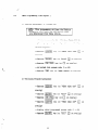
340.1
1.
4.
Programming !%eets
Programming
This area of the programming provides for selecting the
length of time before recall of non-exclusive
held calls
and of exclusively held calls. Tne time-out
on hold
doesn’t begin until the telephone handset is returned
to the’cradle. Address 4 is used to select the timing.
Buttons 7 and 8 are used to select one of the time-outs.
The default value for hold recall is 60 seconds.
Details
Work Sheets
The following programming work sheets, along with
the programming overlays are intended to ease programming work sheets, if kept up to date with respect
to program changes, can also be used as record of existing installation.
In the following pages the words “default value” will
be seen. This is the value which has been programmed
in the Resident System Program and is the value which
will remain if you “default”, (if you do not change the
value). The following symbols are also seen in the programming work sheets:
Hold Recall Timing (See Fig. 340-4)
5.
System Refresh Basis (See Fig. 34G-5)
System refresh (a “cleaning”
of system RAM to
remove any false data caused by AC voltage problems
or other causes) can be set to begin after one of two
conditions have been met for a period of approximately five hours.
1)
There is no change in status; devices may be
busy but no new activity has taken place in approximately five hours.
2)
All stations have been idle; all stations have been
“ON HOOK” for approximate!y five hours.
Kl
340.2
LED
LED
OFF
ON
Memory
Address 5 is used to program this choice of system
refresh basis. Button 8 is used in a either/or mode to
select the style of refresh. The default value is no
change is status.
Block ‘I
Recall Button Timing (See Fig. 340-l)
This area of the program allows choice on a system basis
of how long the disconnect signal produced by depressing the recall button on the keysets last. The recall
button can be used for “flashing” when behind a PBX
or as a recall button when the system is connected to
Central Office lines. Address 1 is the memory location
used to select this tire-out.
Buttons 7 and 8 offer
time outs of 0.4 seconds, 0.6 seconds, 1.0 seconds, or
1.5 seconds. The defau!t value is 0.4 seconds.
340.3
1
”
3.
:---
2.
Page 300-12
Night Mode CO/PBX
(See Fig. 340-7)
Ringing
Assi~ment
This area of the program is used to assign stations to
ring when the system enters night mode. A station
programmed for Night Mode Ring will ring for all 6
COjPBX lines. Addresses 13 and 14 are the assigned
memory locations for all 16 stations. Each button
1 - 8 represents a station. The default value is stations
1 and 9 which ring for all CO/PBX lines. When the systern is in night mode.
Paging Time -Out (See Fig. 340-3)
This area of the program is used to set the duration of
internal and external paging. Possible values are 30
seconds, 90 seconds, or no time out. Address 3 is used
to select the duration of paging. Buttons 7 and 8 select
the time out value. The default value is 60 seconds.
Day Mode CO/PBX Ringing Xssig:ment
(See Fig. 340-6)
This area of memory uses 12 addresses. Each CO/PBX
line uses 2 addresses for ring assignments. This allows
flexible ring assignment for all CO/PBX lines. Each
address uses 8 buttons: each one corresponds to a stations 1 and 9 ring for all CO/PSX lines.
Pause Timing (See Fig. 340-2)
This area of the program selects on a system basis the
duration of the pause interval by the depression of the
pause button on the keyset. The pause button can be
used when programming for station or system speed
dialing where intervals between dialing patterns may be
desired. Address 2 is used to select the duration of the
pause. Button 8 offers a duration of 1.0 second or 3.5
seconds. The default value is 1.0 second.
Memory Block 2
3.
Door Phone Assignment (See Fig. 340-8)
This program area is used in enabling Door Phones
when connected. Two Door Phones can be installed in
the system. Address IS is used to assign this opticn.
6
Button 7 represents Door Phone 1 and button 8 represents Door Phone 2. The default value is that Door
Phones are not assigned. A Door Phone that is connected to the MDF and not assigned in the system
program (NPM) will not operate.
4.
Door Phone Chime Assignment
(See Fig. 340-9)
When Door Phones are installed in the system it is
necessary to assign station(s) within the system to
chime when the Door Phone, is activated. Each station
can be programmed to cl-&ne on Door Phone 1 and/or
Door Phone 2. Addresses 16 and 17 are used to assign
stations to chime when Door Phone 1 is activated.
Addresses 18 and 19 are used to assign stations to
chime when Door Phone 2 is activated. Buttons 1 - 8
of each address corresponds to a station. The default
value is stations 1 and 9 will chime for Door Phone 1
and Door Phone 2.
5.
Off-Hook
Ringing Assignment
1.
Memory
Internal
Block
3.
4.
5.
2.
Attendant
Station Assignment
(See Fig. 340-I 1)
*.
For incoming
Calls
Private Line Ass@ment
(See Fig. 34C-15)
(See Fig. 340-I 2)
Thisarea of the program is used to assign 2 stations as
/
/
Prime Line Pick-Up
(See Fig. 340-14)
Two lines in the system can be assigned as private !ines.
These lines can be accessed and will provide an led
appearance oniy on the assigned stations. Stations that
are not assigned a private line canno! successfully be
prograiimed
to ring on that line. T-w0 stations can be
assigned the same private hne, and two lines can be
assigned to the same station or two stations can be
assigned a private line each. Addresses 15 and !7 are
used to enter each private iine. Buttons 5 - 8 are used
in a binary format to represent lines 1 - 6. Addresses
16 and 18 are used to enter the stations -&at are
assigned private lines. Buttons 4 - 8 represent the
stations. The default value is that no stations are assigned private lines.
This area of the program is used to assign stations into
Internal Paging Zones. Stations can be in any of the
zones or in no zone, they cannot be assigned to more
than one zone.
Addresses 1 - 4 are used to assign stations into zones.
Buttons 1 - 8 are used in pairs; i and 2,3 and 4,5 and
6, 7 and 8, with each pair representing a station. The
default value is that all stations are not in any zone.
/
I
Assignment (See Fig. 340-13)
This area of ‘he program affects on a systemwide basis
whether COjPBX Iines which are in ringing status are
eligible for Prime Line Pick-up. Address 14, button 8,
sets the value. The default value is that Prime Line
Pick-up will not seize ringing lines.
3
Paging Zone Assignment
Prinae Line Pick-Up
This program area is used to allow a keyset to seize a
selected CO/PBX line without depressing that line’s
button. The line will be selected when it is idle or on a
systemwide basis, the line can be selected when idle or
ringing (see Fig.340- 13). -More than one station can be
assigned the same CO/PSX line as its prime line. No
station can be assigned more than one prime line. Each
to two stations.
address from 6 - 13 corresponds
Buttons I - 4 and 5 - 8 are used to program a CO/
PBX line number in a binary format. For no prime line
the binary number 0 is used. The default value is no
prime !ine assigned for any station.
(See Fig. 340- 10)
This area of the program is used to assign Off-Hook
CO/PBX Ringing on a per station basis. When this
option is programmed, stations that are assigned OffHook Ringing and are off-hook (using the handset) will
receive CO ring over their speaker at haif volume.
Off-Hook
Ringing has a distinct ring from On-Hook
Ringing. Both ringing rate and tone frequency are different. Addresses 20 and 21 are used to assign this
option. Buttons 1 - 8 of each address represents a station. The default value is that stations 1 and 9 ring
off-hook.
340.4
2 stations can be assigned as Attendari
Stations, only
station 1 can progran system data.
Address 5 is used for this assignment. Buttons ! - 4
are used to assign on station, buttons 5 - 8 are used
for the second. The binary format corresponds to the
individual stations DSS number.
Attendant Stations. Attendant Station features are: to
set and cancel Night Transfer, to program and confirm
System Speed Dial and to cancel Security Alarm Signal.
Only these features can be transferred by changing
attendant station assignment. T’ne default value is that
stations 1 and 9 are Attendant Stations. Although any
6.
CO/PBX Line Scan Assignment
(See Fig. 340-16)
This area of the program is used to se!ect which CO/
PBX !ines will be scanned for idle status in response to
a station speed dial request for a CO/PBX line. The
system will always scan from the highest numbered
selected line to the lowest numbered
se!ected line
(from right to left).
Page 300-13
hklte:
77~1 lines cnn be omitted from fhe scm.
Each station is assigned
be made on which lines
spond to a station and
represents the lines. The
scan from lines 2 to 1.
340.5
1.
Memory
Block 4
CO/PSX Line Assignment
(See Fig. 340-I 7)
PBX Access Code Assignment
5.
CO/PBX Group Assignment
(See Fig. 34Cl8)
lt Dialing Assignment
(See Fig. 340-21)
(See Fig. 340-19)
6.
This program area is used to assign a CO/PBX line into
one of three groups. The CO!PBX group assignment
affects tolI and Outgoing
Restiction
Assignment.
Programming a line as “not installed” prevents access
to unterminated
lines and provides for error tone when
the corresponding keyset button is depressed. Address
3 corresponds to CO/PBX lines 1 - 4. Each pair of.
buttons, I and 2, 3 and 4, 5 and 6, 7 and 8 are used
to program these lines into a group. Address 4 corresponds to CO/PBX lines 5 and 6. Buttons I and
2, 3 and 4 are used to program lines 5 and 6 into a
group. The. default value for CO/PBX group is for all
lines to be in group A.
Page 300-14
(See Fig. 31-O-20)
This area of the program is used to select a Toll Restriction format to suit the installation Site Requirements.
In some locations it is necessary to dial a “I” before
dialing a foreign area code and local exchanges have 3digit office codes with the same fomlat as area codes.
If l+ Dialing is entered into the prograrr, calls beginning with 1 (c&s to foreign area codes) wi!l be denied
when the station is Toll Restricted on that line, but
local (for instance to a local exchange 408) will be
allowed. In other Iocations, it is not necessary to dial a
“1” before dialing a fore@ a:ea code; in this case I+
Dialing should be removed fro-m the program.
Address 13, button 8, is used to select which type of
inspection process is desired. The default value is that
l+Dialing is assigned.
This area of the program is used to allow up to 2 single
digit access codes to be dialed without the Toll Restriction Inspection occurring. This allows more flexibility
in Toll Restriction when a PBX station or access code
is to be dialed and inspection is not desired.
Two individual digits may be programmed.
Address 2 is used to enter both single digit access codes
to be allowed without inspection. The buttons 1 - 4
and 5 - 8 are used to write both numbers in binary
from 1 - IO (10 is equivalent to 0 on the dial pad).
The default value is assigned digit “9” as PBX access
__code.
3.
Station Class Assignment
This program area is used in assigning restfictions to
stations. The programming work sheet has a chart which
shows how each class of station 0 - 15 is restricted
with regard to each of the 3 CO/PEX line groups. In
the chart, N stands for Not Restricted, T for TolI Restricted and 0 for Outgoing Restricted. Tine classes range
from Not Restricted on all 3 groups, (class 0) through
Toll Restricted on all 3 groups (class 7), to Outgoing
Restricted on all 3 groups (class 15).
Please note that not
_- ah possible combinations are to be
found.
The default value for station class is 0 (Not Restricted
on all 3 groups of CO/PBX lines for all stations). Each
address from 5 - 12 corresponds
to swo stations.
CO/PBX buttons 1 - 4 are used for one station and
buttons 5 - 8 for the other. The station ciass number
is entered in binary format.
an address where selection can
to scan Addresses 19 - 34 corbuttons 1 - 6 of each address
default value is that all stations
This program area assigns lines as either CO lines, or as
PBX lines to provide for a pause when stations use
speed dial or last number dialed. For proper functioning, especially when TolI Restriction is installed, it is
important that PBX lines be assigned as such.
Address 1 and buttons 1 - 6 are used to program line
assignment. Each button I - 6 represents a line. The
default value for line assignment is all lines are CO
lines.
2.
4.
Digit Rejection
Assignment
(See Fig. 340-22)
This area of the program is used to prevent repeated
dialing of the same digit from the beginning of the dialing process to defeat the Toll Restriction Inspection
Process. This ability has been entered into the program
so that when an exchange “ignores” a particular digit
or digits, if they are the first digits dialed and rnerely
continues to offer dial tone, the Toll Inspection Process
will still be valid. A toll restticted station dialing a
number listed in the digit rejection table will be dropped from the CO/PBX line and receive error tone. Up
to 4 separate digits can be entered.
:
r”
,._
_’
7.
Speed Dial Toil Override Assignment
(See Fig. 340-23)
This area of the program is used to permit or deny Toll
Restricted Stations using the System Speed Dial access
numbers 40 - 59 to override toll restriction. This choice
only
applies to system speed dial memory access
numbers 40 - 59 and all toll restricted stations on a
system wide basis. Address 16 button 8 is used to allow
or disallow system speed dial buffers 40 - 59 toll override. The default value is that System Speed Dial will
override toll restriction.
8.
Toll Restriction
Override Table (See Fig. 340-24)
This area of the program can be used to enter up to 30
3-digit codes to override *the Toll Restriction. Some
uses for ‘&IS table would be to provide access to
commonservicecodessuchas911,61!
and411 andto
allow dialing 800 numbers and selected foreign area
codes. Two addresses are used for each code. The first
four buttons of an odd-numbered
address are used to
enter the first digit. The second four buttons are used
to enter the second digit. The first four buttons of the
following even-numbered
address are used to enter the
third digit. The numbers are entered in binary with 10
equal to 0 on the dial pad. Any address which is completely blank (no LEDs lit) is recognized as terminating
the Override Table so no address can be skipped when
programming. The default value of the Override Table
is that no 3-digit codes are entered.
Page 300 -15
.
_
- ..--.------. .--. -_
i’
Tabse
MEMORY
BLOCK
2
Pause Timing
3
Paging Timeout
4
Hold
5
System
Address
BLOCK
I -
Assiwment
Assignment
Assignment
Recall Timing
Refresh
Assignment
Basis
Day Mode CO/PBX
Night
24
Ringing Assignment
Mode CO/PBX
Ringing Assignment
Door Phone Assignment
15
16-
19
Door Phone Chime Assignment
20-
21
Off-Hook
Ringing Assignment
1 - 4
Internal
Paging Zone Assignment
5
Attendant
MEMORY
Address
Timing
2
12
13-
Block and Address Content
1
Recall Button
MEMORY
BLOCK
6-
3
Prime
13
Station
Line Pick-
Assigilment
Up Assignment
Prime Line Pick-Up
14
for Incoming
i5-
18
Private
i9-
34
CO/PBX
Line Scan Assignment
1
CO/PBX
!-ix
2
PB Access Code Assignment
3-4
CO/PBX
Il/iEMORY
BLOCK
5-
12
14-
15
16
17-
Calls Assignmer;t
Line Assignment
4
Station
Assignment
Group
Assignment
Class Assignment
“1” + Dialing Assignment
13
Page 300-16
Memory
1
Address
Address
340.1
76
Digit Rejection
Assignment
Speed Dial Toll Override
Assignment
Toll
Table Assignment
Restriction
Override
F
MEMORY
BLOCK
ADDRESS
EXAMPLE:
Real!
Button
EXAMPLE:
1
:
7
I
Recall
Fig. 340-I
:
Timing
is set at 0.6 seconds.
Assignment
I
MEMORY
I
ADGRESS
BLOCK
:
4
I-JZJ
3.5
Pause Timing
is set at 3.5 seconds.
.
Fig. WI-2
Pause Timing
Assignment
Page 300-17
I
1
30
EXAMPLE:
MEMORY
BLOCK
ADDRESS
:
1
:
3
1:
I
60
Paging Time out Is se1 at 60 seconds.
Fig. 340-3
Paging Time
EXAMPLE:
Out Assignment
I
MEMORY
I
ADDRESS
BLOCK
:
7
!
:
4
rJ-q
60
Hold
Fig. 3404
Ho!d
Recall Timing
Recall Timing
is se: at 60 seconds.
,
‘1
I
MEMORY
---.-____
BLOCK
f
-___
ADDRESS
EXAMPLE:
:
:5
I
,j15j
System
is Programmed
for
Idle Condition:
Fig. 340-5
System
Refresh
Basis
I
i-
MEMORY
BLOCK
ADDRESSES
In the Day Mode, CO/PBX-3
Stations
:
2
: 7 -
12
wil! ring at
1 thru 7.
Psge 300-19
In the Might Mode CQ,&‘BX 1 - 6 will ring
at Station
Fig. 340-T
1 thru 5.
Night Mode COiPBX Ringing Assignment
MEMORYBLOCK
:
2
ADDRESS
:
75
EXAMPLE:
Door Phone
Fig. 340-8
-_Page
300 -20
Door Phone Assignment
1 and 2 are enabled.
I
MEMORYBLCCK
:
2
AEERESSES
: lS-
I
19
EXAMPLE:
Door Phone 1 will chime at Stations 2,4, 6, and 8.
STATeON NUMBERS
I
16
I
/
17
I 9
/ 10 j 11 1 12 / 13 / 14 / 15 / 76
I
I
I
2
1
18
1
19
9
Fig. 340-9
I
21
31
I
41
I
51
6/
7j
8
I
I
I
I
I
/
!
I8
16
Ooor Phone Chime Assignment
I
MEMORY
:
BLOCK
2
I
: 20-21
ADDRESSES
NO OFF-HOOK
RINGING
OFF-HOOK
RINGING
El
EXAMPLE:
pm
ga
E
/zI
III
Stations
1 thru 4 will ring off-hook.
Page 300 -2 I
,
EXAMPLE:
STATiON
ADD.
-
3
9
4
13
Fig.
Page 300 -22
343-l 1
I
Internal
14
ZONE A
STA. 7:
STA. 8:
ZONE C
NO ZONE
NW.‘?BERS
10
/
j
STA. 5:
STA. 6:
!
11
j
72
15
/
l6
Paging Zone Assignment
ZONE B
.‘_
,
/
MEMORY
i
BLOCK
ADDRESS
:
3
:
5
/
IIIlmm141
STA.
EXAMPLE:
lzHzzml[81
1
,Stations 7 and 10 are assigned as Attendant
2
‘^----_._,_^i.~
1
Stations _
_,_.t
3.
4
1
5
ADD.
/
,
2
3
6
141.6
ATT. STi+TlQPd
/
/
7
I
I8
ATT.STATION
5
6
7
8
9
q
10
11
12
13
14
15
16
Fig. 340-l 2
Attendant Station Assignment
Page 300 -23
/..
: 6-13
ADDRESSES
EXAMPLE:
I
I
lzlfl
.
Station
4
1 is assigned CQ/P5X
as prime
line and, Station
CO/PBX
Line 1 as prime line.
Line 3
2 is assigned
Kl
I
Fig. 340-13
Prime
Line Pick-Up
Assignment
MEMORY
1
ALLOW
ADDRESS
:
‘:
3
14
Kl
EXAMPLE:
DISALLOW
BLOCK
’
f
‘.______.
System
is programmed
TV allow prime
line pick-up for incoming
Fig. 34Q-74
Page 300 -24
Prime
Line Pick-Up
for homing
Calls
calls.
MEMORY
BLOCK:
ADDRESSES
3
: 19-
34
NOT SCAN
SCAN
q
EXAMPLE:
Station 2 is assigned scanning CG/PBX
3 and 1.
1 /jLINE 2 j UME 3 j LINE 4 / LZME 5 / k!NE 6)
Fig. WI-16
Page 300 -26
CO/PBX Line Scan Assignment
Line 6,
’
EXAMPLE:
MEiMORY BLOCK
:
4
ADDRESS
:
1
5g%D5
I
Line 1 and 2 are assigned
6 are assigned
as PBX.
ADD.
1
2
LlNE I
LIME2
Fig. 340-17
3
4
5
1
as
CO Line 3 tkru
ci
LIME 3 LIME 4 /LIME 5 LlNE 6
@Q/PBX Line Assignment
Page
3CN-27
EXAMPLE:
1
COfFBX 1 - 2 = A
=b
CO/FBX 3
=C
CO/FBX 4
ADD.
co.
1
CO.
2
/ 4
3
CQ.
5
6
7
CQ.
I
3
4
1
5
\ ..*
/”
2
.
6
Fig. 340-19
,,
‘T
3
.
CO/PSX Group Assignment
4
I
8
...I
.
..-..
...___..I
1.0
PBX CODE
EXAMPLE
FIC’I
g%
PBX access codes have been set at 9 and 6.
2
3
4
5
6
7
8
9
0
NONE
Fig. 340-18
Page
300 -28
PBX Acces5 Code Assignment_,
____.__ -..
c
El
El
_u)
1-
M
‘..
‘\.
.\
MEMORY
BLOCK:
4
:
ADDRESS
I
13
I
I
m
EXAMPLE:
DISALLOW
1 8
ADD.
System
13
is programmed
to permit
“I+”
dialing.
Fig. 34021
1f Dialing Assignment
MEMORY
BLOCK:
ADDRESSES
I
4
:
14 - 15
3
DIGIT
EXAMPLE:
m
1
Syctem programmed
2
to release line when
first digit 3 or 6.
3
4
5
6
7
8
9
0
NONE
Fig. 340-22
Digit Rejection
>!
Page 300-31
_. __-.. --- ..-.-
._-__
---
-.-- ___._
i”r
EXAMPLE:
DISALLOW
I
System speed dial is restricted.
Fig. 340-23
Speed Dial Toll Override
‘
Assignment
/
MEMORY
BLOCK:
4
: 17-76
ADDRESSES
I
DIGIT
EXAMPLE:
m
1
2
3
The first 3-digit code in this table is 212.
4
5
ADD.
6
11213
17
CODE DIG. 1
18
CODE DIG. 3
415
6
I
;7
18
CODE DEG. 2
7
,
CODE DIG. 1
CODE DIG. 2
75
CODE DIG. 7
CODE DIG. 2
76
CODE DIG. 3
19
8
9
0
Fig. 340-24
Page 300-32
Toll Override Table
TOLL OVERRIDE
TABLE CHART
Fig. 340~2Ei
Page 300-33
_.
_____~.__.__._ __.._ _--___
.-.---..---
-----.-
---.-----...
--.”
-.--“I--
--....___
--------.h
USER DIALS
A DIGIT ON
A COlPBX LINE
ALLOW USER
FREE DIALING
ALLOW PBX
ACCESS CODE
l+ DIAL
DIRECT
AREA
DIAL
AREA
0
0
l-9
.
1
DIGIT
Fig. 340-26
Page 300 -34
Electra-616
Toll Denial
Algorithm
TOLL
pm
SECTllON
410
Key Telephone
410.1
CO/P5X (Outside Calls)
1.
400
STATION
OPERATION
Operation
PROCEDURE
Use of station or system Speed Dialing can automatically seize an acceptable COjPBX line eliminating
the need to depress II CO/PBX line. For 4 pnrticubu
CO/PBX line, depress CO before depressing the
Originating
Using Manual Dialing
Using Prime Line Pick-Up
-
depress idle (unlit)
-
lift handset or depress
-
receive dial tone
-
dial desired number
-
when party answers, use handset .to talk
m
3
q
-
lift handset or depress
-
receive dial tone
-
use any of the dialing methods discussed here
Note:
For consecutive dialing, depressing the Speed Din1
Key initiates speed dialing at any time. The keypad
Using Last CO/PBX Number Redial
-
depress idle (unlit)
-
lift handset or depress
-
receive dial tone
-
depress Last Number Key
-
display shows m]
-
when party answers, use handset to talk
is ah4ys
live for manual
dialing.
~
2.
a
,$
III
s
tl
3.
Answering
When a slow Flashing
co
-
depressing flashing
q
-
lift handset
-
respond to caller
is present on Keyset
Placing a Call On Hold
Using Speed Dialing - Station and System
Placine a CO/PBX Call on Non-Exclusive
-
depress idle (unlit)
-
lift handset or depress
during
B
q
CO/PBX conversation,
depress [HOLDIonce
s
-
receive dial tone
-
depress Speed Dial Key m
-
display shows VI
display shows m
or,
-
For Station Speed Dialing
-
Hold
1
depress m
automatically
Note:
depress desired m
for KM call. The ca3.l in progress will
be put on hold.
Depressing the page, door phone or pick-up buttons
will also automatically place the CO call on nonexclusive hold and activate the selected feature.
,
or,
Placing a CO/PBX Call on Exclusive Hold
For System Speed Dialing
-
dial 20 - 59 for the particular
-
display shows Speed Dial Buffer Number mj
number desired
-
during CO/PBX conversation,
-
display shows [m
depress [HOLDItwice
Page 400-l
depress B
Removing a CO/PBX Line from Hold
-
depress fluttering
-
lift handset
or intermittent
winking
for desired station
(if a previous CO/PBX call was in progress, the call
is placed on hold automatically)
Ic6
receive tone burst
4.
Hold Recall
display shows called station number
m]
after response, use handset to talk
An audible recall signal, a fluttering COIPBX LED
and a display are provided to idle keysets that have
To a Busy Station
longer than the programmable
-
time.
-
same as above (first 3 steps)
display shows IT]
-
receive call waiting tone
X corresponds
-
wait until called station answers or restore handset.
Note:
Calling party will receive busy tone when called
station is in Do Not Disturb mode or receiving an
ICM call. The called station’s display wit! not show
the calling station’s number.
to CO line recalling
-
depress fluttering
-
lift handset
Note:
m
Display will indicate the held lines of the station
sequentially, for 0.8 set each.
2.
5.
Answering
Abandoning
a Call
Idle Station
Abandoning
a Call
-
receive tone burst
-
at the end of the call, depress the Recall Key
-
-
CO call is released, but the line is retained and new
dial tone is heard.
display shows calling station’s
ICM Flashes
-
converse hands-free or pick-up handset
-
dial next call
Abandoning
-
restore handset
-
CO/PBX line is released
-
-
-
depress
$$
•I
when in Monitor Mode
1.
,s
q
(Internal)
Calls
To an Idle Station
lift handset or depress
Page 400-2
display shows calling station’s
ICM Flashes
depress m
and converse
number
immediately
1-1
with call-
continue
existing CO conversation
LED goes off and CO/PBX line is released
Intercom
,
receive half volume tone burst from speaker
or
-
Originating
-
1x1
ing party,
Note:
410.2
number
Busy Station on COjPBX Line
Using Handset
Abandoning
.
$
cl
After call is abandoned and busy station becomes
idle, the display will show the number of the last
ICM party that called for 3 seconds.
,
Conferencing
410.3
410.4
r
circuit is busy, g
will light
cl
on all keysets. No additional conferences
can be
made at this time.
1.
allowable conference
configurations
2 stations
1 CO/PSX line
1 stations
2 CO/PBX lines
3 stations
No CO/PBX lines
(1 station
line)
1.
2 CO/PBX lines or 2 stations
depress m,
-
after receiving tone burst, voice page to request
called station to pick-up held CO/PSX line.
-
wait for response or monitor held CO/PBX status
until answered (CO lit steady).
El
2.
flashes
depress m,
mislit
conference
is established,
Three party conference
Ei
use handset to talk
(3. internal parties)
1.
flashes
wait for called party to answer with handset
conference
Nota:
E\
use handset to talk
Calfed KM party must answer with handset to
established conference.
Holding
1 Station
2 CO/PBX Conference
depress @,
Nota:
both m
depress m,
To
Leave Do Not Disturb Mode
-
depress [q
m
is lit
~/DNDJis off
The following speaker activity will stop when a
station enters Do Not Disturb Mode: COIPBX ring,
ICM calls. paging and door phone ring.
Intercom
Call Pick-Up
To Pick-Up an Intercom
/
Call to a Station
-
lift handset or depress
-
depress Call Pick-Up Key
-
display shows m
-
depress [DSSIof called station
$$
c3
- use handset to talk
is lit
is established,
-
410.6
depress 10551 for desired station
depress El,
winks
Do Not Disturb
Note:
with KM call in progress
depress B,
,m
To Enter Do Not Disturb Mode
1 CO/PBX
originate CO or ICM call and wait for called
party to answer
--.
depress desired !,,,
410.5
with CO or ICM call in progress
-
-
restore handset
Three Party Conference
2.
during CO conversation
are:
Originating
a
When the conference
Note:
The
Transfer
wink
Paging
410.7
1.
Internal 3-Zone Paging
To Originate an Internal Zone Page
-
lift handset or depress
-
depress Paging Key
-
display shows /?/l
,s
e
This allows individual handling of the two CO/
PBX calls. Conversation cannot continue during
the station’s absence.
Page 400-3
_..^_,.. _- _ _.-_../.___---.._._I..-...I- ._”..
,
-
II
for Internal
121for
-
-
on keypad dial
Zone 2
i
for Internal
Zone 3
141
for All Internal
use handset to talk
..”
.
!
X digit dialed on keypad
Zone 1
Internal
.- _..^...,
--.-.-I ..-__. ___I -._-....._._.___. ,_j___..__._,,_.
-.
To a Busy Door Phone
-
lift handset or depress
s
I
-
depress door phone key
-
display shows r]
-
on keypad dial m
-
receive busy tone, display goes off
Zones
display shows 1-1
X digit dialed on keypad
2.
External
Paging
or 121
To Originate an External Page
2.
-
lift handset or depress
-
depress Paging Key
-
display shows 1p]]
-
on keypad dial 151
-
display shows I]
-
use handset to page
Answering
s
u
To Answer Any Internal
display shows ]F]
-
lift handset
-
depress door phone key
- on keypad, dial m
3.
3.
-
lift handset or depress H
-
depress paging key
-
display shows
-
depress m
-
display shows m]
-
use handset to talk
[PI]
on keypad
410.8
1.
or 121
use handset to talk
-
depress
-
depress door phone key
-
display shows [I
-
on kevuad
dial IIm
-.
-
display shows m]
2
Ll
or /21
X digit dialed on keypad
410.9
.
1
Monitoring
or External Page
-
or ]d/21
Door Phone
1.
Programming
I
Speed Dial
Originating
To Program
Idle
To an Idle Door Phone
-
depress ‘-1
-
record tone is heard over speaker
depress door phone key
-
display shows m]
display shows IF]
-
depress desired B
-
display shows
-
record tone stops
lift handset or depress
on keypad dial m
display shows m]
Page 400-4
e
G
or /21
Station
Speed Dial with Key Telephone
Key
m
number
m]
4
-
dial telephone
-
each digit is displayed as dialed [T]
With Key Telephone
-
depress I]
-
-
display goes Off
3.
number
Key
To Confirm Station Speed Dial Number
Key Telephone has 16 SPD buffers,
each, available for its own use.
16 digits
4.
2.
depress Speed Dial Key ISPD]
- depress desired B
Each
Note:
Idle
display showsm
number
stored number sequentially
and each digit of the
To Confirm System Speed Dial Number
To Program System Speed Dial
With Key Telephone
(Attendant
Keyset Only)
-
-
depress -1
-
record tone is heard over speaker
-
display shows [m
-
dial desired buffer number
-
record tone stops
-
dial telephone
-
each digit is displayed as dialed 171
-
depress 1SPDPfiOG] Key
-
display goes off
Idle-
depress Speed Dial Key m
Key
-
on keypad dial desired buffer 20 - 59
:.
:.
~.
- display shows buffer number and each digit of the
stored number sequentially
m]
Note:
when there is no memory
in buffer.
number
Note 1:
The system is provided with 40 System Speed Dial
access buffers, 16 digits each. The access numbers
are 20 thru 59.
Note 2:
When programming station or System Speed Dial,
a pause may be inserted at any time. Each sequential depression of the pause key will increase the
duration of the pause. Each pause will count as a
digit.
Note 3:
Display shows I]
To reprogram a speed dial buffer, follow the same
instructions as programming. To erase a speed dial
buffer. follow the instructions for programming,
but don’t enter a telephone number.
410.10
1.
Night
Mode
To Enter Night Mode
With Key Telephone
2.
Idle
-
depress @
-
display shows I-I-]
-
on keypad dial 161,
-
display shows 1611
-
depress PI,
-
display shows ml
Fj
181
is lit
for 10 seconds
To Cancel Night Mode
With Key Telephone
Idle
depress @
display shows I--i_]
on keypad dial m’,
q
display shows 16181
depress [HOLDI,m
goes out
Page 400-S
410.11
.
Security Alarm
Display shows [Tj
1.
To Cancel Alarm
With Key Telephone
-_
or (nlzl
Idle
-
depress m
-
display shows [F]
-
on keypad dial 171,
-
display shows [T]
-
depress B
-
alarm stops, display will remain until circuit is reset.
After reset, display goes out.
Page 400-6
181
._
..
I
J
.
.
This addendum supplements the Electra-616 Installation Service -Manual
ND-17314.
This
addendum should be
installed in an B-6-(
)
used whenever a
KSU and when an EIXH-(
)
CRJ-SA KTU
is
Key Telephone Set with
built-in speakerphone is installed in an Electra-616 system. Because all
ES-6-3 KSU's initially contain a CFU-SA KTU it is recorrmendedthat all
installation and maintenance personnel become familiar with this addendum.
i
:
.
/
-.
This addendumis dividedinto four sections:
100
E;T-6H-(
) Key TelephoneSet with InternalSpeakerphone
200
CharqesinStardard ProgramingwithCIlU-SA
300
Menu Prqraming
400
How to OperateNew Features
AccessCode List
Alphanumeric
DisplayCharacterList
-2-
100
ET-6%()KEYTELEPEKlNESETwI?xINrFPNAL
110
Installation
spEAKERP=
From a hardware stardpoint, the EZXiE+( ) Key Telephone
set is installed exactly as the ET-6-I ) Key Telephone set.
Cable and connector requirements remain the same.
power source need be provided for the ET+%-(
I.20
)
No
local
speakerphone.
Programunir-q
In order to initiate intercom calls with the ET-BI-( )
internal speakerphone, the
station must
be
assigned as
a
hands-free telephone in the system program.
See Figure 12O.l.A.
An alternate way of prograrrmingthe ET+X-(
)
from the station
as a speakerphone is provided by Section 300 menu programming.
See Section 320 Menu Programning From Any Keyset.
I
ET-6H-(
ET-6-(
)
)
1
MEMORY
I
ADDRESS
BLOCK:
9
1
: 2-3
1
I
I
STATIONS
ASSIGNED
STATIONS
ASSIGNED
...
L
Figure 120-l
A: Hands-free
-6-
Telephone
Assignment.
1 _
AS
5 u
AS
4 ARE
ET-GH-(.
)
8 ARE
ET-6-t
) _
200
CHAG~INSIANDAPDPIUQUMIING
210
Programming Operations
All programming procedures remain standard as in Section
300 of the Electra-616 Installation Service Manual NE-17314.
This includes all procedures for going off-line, for selecting
memory blocks and addresses, for entering data, etc.
210.1
Programming Details
Several parameters have been added to the programrrable
contents of the system memory, these are:
--Privacy release which disables privacy on
selected
lines enabling up to four stations to talk to an outside
partyon any CD/pBX line assign& to be without privacy.
--Assignment of
ET-G&(
)
Key
Telephone
Sets
with
internal speakerphone to allow full hands-free operation
including initiation of intercom calls.
--Selection of a vacant station position to enable tarxlem
conference (a tandem conference being an
conferexe
of two outside (a/PBX)
unsupervised
parties with manual
re-entry to monitor conference status),
--A
method
of
resetting
the
system
by
programming
(without using the momentary button on the CPU) has been
added.
-c;-
220
/
Default Values
.
The default values for these additional parameters are:
--Privacy release:
All a/P%X
lines retain the privacy
feature.
--All stations are m-6-(
)
Key
Telephone sets
(no
internal speakerphone).
--Tandem Conference is allowed when station 8 is not
installed; when station 8 is installed there is no Tar&m
confererxe allowed unless another station position with
no station installed is chosen and programned.
230
ProgrananingDetails
230.1
Memory Block
8
1) System Reset.
If
system reset.
This memory block is only used to do a
this memory block
is selected while
the
programming station is in off-line mode, the entire system is
reset (just as it wuld
CPU-SA).
The
be by depressing the reset button on the
progrannninq station returns
to
on-line mcde
because of the system reset and all calls in progress will be
--depress [XZRii[
--depress m
--depress m,
--depress v_al
-6-
a,
j5J
Reset occurs at this time with the progrming
station returning
to 'ton-line"mode.
230.2
Memory Block 9
1) Privacy Release Assignment (See Figure 340-27).
Any
ccambinationof cO/PBX lines can be selected to lose the privacy
feature.
This
enables
up
to
four
stations
to
join
a
conversation with an outside party on the chosen CD/PBX line
without privacy.
Parties attempting to enter after a fourth
party has entered will receive error tone. The default value is
that all CD/PBX lines retain the privacy feature.
buttons 1 r- 6
are
used with
each
button
Address 1
representing its
corresponding CI/PBX line.
2) Hands-Free Telephone Assignment (See Figure 340-28).
With the introduction of the ET-a-(
) Key Telephone Sets this
area of the program is used to allow hands-free initiation of
intercom calls.
buttons l-
Addresses 2 and 3 are used with each of the
8 representing a station in each of the addresses.
The default value is that all stations are ET-&(
)
telephone
(without internal speakerphones).
3)
Tandem Confererxe Assigrxnent (See Figure
340-29).
This area of the program is used to reserve a station position
to be used for tandem conferences. A tandem conferexe is an
-7-
unsupervised two CD/PE3X line conference with exit and re-entry
available to the station which originated the copfereme.
Address 4, buttons 4 station
position
reserved
for
corresponding SW-S K!TU must be
8 are used to designate the
tandem
installed.
conference.
If
The
the selected
.station is later installed it will take precedence and the
tandem conference feature will becune inoperative. The default
value is that the position of station 8 is reserved for tandem
conferences.
-e-
1
MEMORY
BLOCK:
9
1
9
]
ADDRESS
I
ALLOW
CO/PBX lines 1 thru 3 will
allow privacy release.
Figure 340-27:
Privacy Release EnaQie Assignment
Stations
Figure 340-28:
STATION
I
2
1
3
9
2
3
MEMORY
1
ADDRESSES
1 thru 4 are assigned
Stations
1~00
1
5 thru 8 are assigned
NUMBERS
4
5
617
i
81
10 11 12 13 14 115 16
Hands-Free
Telephone
Assignment
BLOCK:
: 2-3
as Hands-Free
as Standard
/
Te!.
Tel.
/
f
1
1
MEMORY
BLOCK:
ADDRESS
-
/
Station
c
STA
q
Tandem
6
16 is assigned
Conference
1
2
3
4
5
6
7
8
cl
El
t3 El
I3
9
10
11
12
13
14
15
16
Kl
I3
I3
Kl
Figure 340-29 . -bandem Conference
K.,,.
_
1n
-
Line Assignment
Line
9
:4
j
1
300
MlMJPxxEWT4ING
Menu programming is a
Electra-616.
new method of
programming the
Menu programming supplements the standard system
programming and can be performed partially from the programming
station (Station 1) and partially from each individual station.
Not all parameters can 'bechanged via the menu prograrmningmode.
Parameters which can be programmed from station 1 using
the menu mcde are:
--Feature Assignment - one of 48 possible selections is
chosen to fit the system requirements (See Table 3OC-2-J)
--Ringing Assignment (per trunk, per station basis)
--Call Restriction (outgoing toll and non-restriction on
a per trunk per station basis).
Parameters which
are
programned from
station sets are:
--Prime Line Pickup
--Speakerphone (ET&H-( ) assignment)
--Off-hook ringing
Detailed procedures for menu programming follow.
the
individual
.
310
Menu ProgramninJ From Keyset 1
1) Feature Assignment (1 &&rough 48)
*
m:
This programing utilizes the Feature ’
AssigrrmentMenu table and all access codes
are determined from Table 3OC-1A_
--choose access code (l-48)
--place programing
from Table 300-lA
overlay
(when available) on
station keyset 1
--depress /m
key (or "MENJ PEW
CUT" a
on
overlay)
--depress [oN/oFr"lkey (or "EXIT" a
--depress -1
key (or a
on overlay)
on overlay)
--on keypad dial access code (1~ 48)
--depress F\
key (er "MENU ENTER" on overlay)
2) Verifying Program Acceptme
--depress
overlay)
--depress 1-1
--depress mj
--depress [md
key (or "MIT"
key (or a
key (or
“MENU
@
on overlay)
on overlay)
READ c3.n”
hi1
on
overlay)
--display shows programed access cede (l-48)
--depress 1-1
-l2-
key (or "MIT"
H
on overlay)
3)
Ringing Assigment
--place
programming overlay
(if available) on
station keyset 1
depress -1
key (or
“MENLJRFAD CXJ’F m
on
overlay)
--depress
/m
--depress [SPDI
key (or "EXIT" a
key (or
q
on overiay)
on overlay)
-depress ]Mlcl key (or "PJ%m on overlay)
--depress desired station select key (1 -16)
to
be programed
--depress desired line key(s) (i -6)
to ring at
selected station
--repeat last two steps for each station beir-!g
programed
--depress [CPJ/OFFjkey (or "EXIT"
q
on overlay)
4) Call Restriction
I
NOTE: Visual indication at each cO/PBX iine
button (l-6) identifies the type of restriction for that line. Each button
depression changes the restriction status of
associated a3/PBX line.
= Non-restriction
IDLE
= Toll restriction
STEADY
(depress once)
ETASHIN; = Outgoing restriction
(depress twice)
Depress third time to return to IDLE.
J
--place
programming overlay
(if avail&le)
on
--depress JTKEWCR[
key (or "MENU REFD OUT" a
on
station keyset 1
overlay)
--depress JON/OFF1key (or "EXIT" a
--depress m\
on overlay)
key (or 3 on overlay)
--depress m
key (or "RESTRICT" on overlay)
--depress desired station select key (l-
16) to
be progranmzd
--depress desired line key(s) (lr-,6) to be restricted
at selected station - see note abve
for LED status
irdication of the various restriction states
--repeat
last
two
steps
for
each
station
being
progranxned
--depress 1-I
key (or "EXIT" B
on overlay)
5) System Reset Using Keyset.No. 1
--depress JADD/ONJ key
(or "PlEbKJFZAD CVI?
a
overlay)
--depress 1-1
key (or "EXIT" B
on overlay)
q
--depress q
--depress
--depress a
L-depress IDsss[
--keyset No. 1 is now in "on-line" mode
-
14 -
on
320
Menu ProgranxtingFrom Any Keyset
la) Prime Line Assignment - With Key Telephone Idle
--depress -1
key
--display shows B
--record tone is heard over speaker
--depress desired cO/PE!Xline key
--display shows chosen CD/M/line
iL';1
wi.th*=ld6
--record tone stops
--depress 1-i
key
--display goes off
lb) Cancelling Prime Line Assignment - With Key Telephone Idle
--depress w[
key
--display shows @
--record tone is heard over speaker
--depress )m
key
--display shows ]nL1 for 3 seconds
--record tone stops
\
_..
2a) H&s-Free
Telephone Assigrnnent- With Hands-Free Telephone
Idle
--depress m
key
--display shows m
--record tone is heard over speaker
--depress 1-1
key
--display shows m
for 3 seconds
--record tone stops
2b) Cancelling Hanls-Free Telephone Assignment
--depress 6-1
key
--display shows a
--record tone is heard over speaker
--depress r-1
key
--display shows @
for 3 seconds
--record tone stops
3a) Off Hook Rirqing Assignment - With Key Telephone Idle
--depress rSPD PEG1
key
--display shows m
--record tone is heard over speaker
--depress lm
key
--display shows m
--record tone stops
- 16 -
for 3 secords
.
/
3b) Cancelling Off Hcmk Ringing Assigrment - With Key Telephone
Idle
--depress IpRo
key
--display shows B
--record tone is heard over speaker
--depress [PPGEIJkey
--display shows m
--record tone stops
- 17 -
for 3 secords
400
K>kJTooPERAlT
/
Group Call-Pick-Up
- With Key TelephoneOff-Hook
--depressl-up1
key
--displayshows IupJ
--depressm
key
--displayshowscalled stationnumber m
Call Back I&quest
Upon receivingno answer (or busy indicationat
called station:
--depressa
--displayshows a
for messagesent (or /TJ for
messagedenied)
keysetcan receiveup to tw
call
back requests. Displayshowing@
indicatesthere are alreadytxo call back
requestsfor the called station.
N(Y.L’iZ:
Each
TandemConfererxeCall
’
One stationpositionmust be vacant
for systemto providetandemconferexe
capabilities.
NC?CE:
‘
I
--establish comication
--depress
with a CI/pBX line
/ADD/ON1 key
--CD/PBX line key LED shows hold indication
--establish communication with second CD/PBX line
--depress [ADD/ON{ key
--both m/PBx
line keys arkd [ADD/ON{ key LED
indicators light steadily (the two O~/?BX lines
ard the station are in confereme)
If stationdesires to leave conference while maintaining
the two CD/FBX lines in tandem conference:
--depress rwl
key and'go on-hook
--LADD/oNL key irdicator flashes, both CD/PBX iine
indicators light steady
To re-enter tandem conference:
--go off hook ard depress -1
--I-/
key
indicator
key
lights
steady
and
confererxe can be heard via hatiset
--if
tandem
confereme
is
finished,
restore
handset to release both CO/FBX lines
--if the tandem coriferem=eis still in prqress,
depress /m\
key and restore hardset
--continued--
-
1-9 -
--1ADn/crJ7indicator
flashes, both C$&EIX
line
/’
irdicators
light
steady,
tandem
continues
1
NUIE: Approximately 3 minutes into the
tandem conference, an audible time reminder
is provided and the I-1
key indicator
starts fluttering. Thereafter, every 3
minutes the tone reminder will be heard until
the tandem conference is re-entered and
terminated.
conference
330
Job
Instructions
330.1
PRIME LINE. This assigns a “Prime Line” wltich
will be seized by a station going “Off-Hook”
without depressing COjPBX button. Ihis feature
will only poerate when the “Prime Line” is in idle
status unless a separate programming choice is exercised; then the line will be seized when ringing or
idle.
Specifications
for Completing
Job Specification
1.
The fist page contains items A - C and 1 - 5. These
have been provided as a convenience and do not affect
programming.
2.
Item 6 is COjPBX Assignments. Much of this table is
also provided as a convenience. Two sections, REFERENCE NUMBER and PFROGRAMMING
DATA, are
used in programming.
PRIVATE LINES. This assignment provides space
to record which station and wlhich line on that
station will be programmed for a private lie. Note
that only two lines can be assigned as private lines,
Two stations can be assigned the same private line,
and two lines can be assigned to the same station.
REFERENCE NUMBER is the number the CO/
PBX line will be referred to in programming
material.
9
INTERNAL ZONE PAGE. This assigmment provide
space to record zone paging groups: 1, 2 and 3.
Any number of stations can be in a zone, no station can be in more than one zone. All stations
rarrain in the “all call” group.
PBXLINE refers to the origin of ;he line connected;
is it from a PBX or from a Central Office? This will
affect speed dialing, last CO/PBX number redial
and restriction features.
c> LINE
ATTENDAI\(‘T STATION. This assignment provides space to record 2 attendant station positions.
The station (s) programmed as an attendant station
is capable of performing the following additional
functions: to program and confirm system speed
dial, to set and cancel night transfer and to cancel
security alarm signal.
GROUP (A, 5, C, or NOT INSTALLED).
Every CO/PBX line installed must be assigned a line
group, even if all lines are in the same group. At
the time of installation all CO/PBX lines will be in
Group A as is provided by the resident system
program. Every installed CO/PBXline circuit wfiich
does not receive a CO/PBX line must be assigned
as NOT INSTALLED. This will prevent access to
unterminated
circuits. Restriction feature is also
affected by this assignment.
3.
DOOR PMONE CHIME. This assignment provides
space to record which stations will &ime when
Door Phone 1 and/or 2 are actiiiated. Any number
of stations can be assigned to c_hime fOi either or
both Door Phone 1 and Door Phone 2.
Item 7 is Station Assignments. Two sections of this
table are used in programming, reference number and
programming data.
CO/PBX LINE
REFERENCE NUMBER is the station’s DSS Number and is the number the station will be referred
to in programming material.
CO/PBX RING ASSIGNMENT provides space to
record requirements for day and Night Mode Ring
and OFF-I-Iook Ring. When a station is to ring in
any of these requirements,
place an appropriate
mark in the space provided. The station programmed for night ring will ring for all CO/PBX
lines when system is set for Night Mode Ring.
RESTRICTION CLASS and CGDE. Only the class
is required for programming. Each CLASS has a
unique CODE, and adding the code will make
understanding
the restriction easier. See the table
located on the Station Class Assignment Table in
Section 340 Programming Work Sheets.
Page 300-h
I)
4.
CO/PBX LINE SCAll. This section provides space
to record which CO/PBX lines will be scanned by
individual stations when speed dial is activated.
The system wili start no scan from the highest line
number programmed for that station. Prirre Line
Pick-up feature will have priority over Line Scan
feature.
Item 8 is System Assig,nments. These assignments 2ppIy
system wide and include Time Outs, Door fhone Connection assignment, Prime Line for incoming calls and
Toll Restriction assignments.
A)
TIME OUTS are listed with durations in seconds.
The desired Time Out can be circled.
_