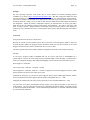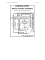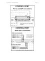
1
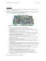
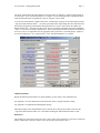
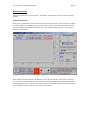
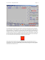
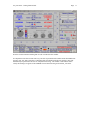
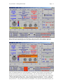
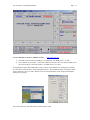
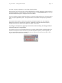
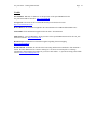
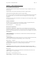
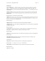
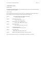
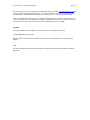
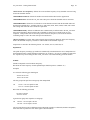
ZL2AMD’s
Uni_Trac 2003
Help & Getting Started Guide
Upgrade to the existing parallel port hardware and new Version 4 USB/Serial hardware
Last Updated August 2003
Uni_Trac 2003 - Getting Started Guide
Page: 1
Caveat
I retain the intellectual property rights to the entire Uni_Trac xxxx system - namely the concept, circuitry,
firmware, hardware format, software and packaging.
As I am not financially involved in, or receive any financial gain, in the sale and distribution of the
Uni_Trac 2003 system, all user requests for support must be addressed to:
Terrig Evans
e -mail: [email protected]
E. T. Electronics
16 Davidson Avenue
Pirimai
Napier, 4001
New Zealand
In the event of a genuine malfunction found within the Uni_Trac 2003 software itself I will investigate the
matter and release an updated version to the www.etelectonics.com site. Address the malfunction report to
E T Electronics in as detailed manner as is possible.
David Lamont
ZL2AMD
July 27, 2003
Contents
I.
II.
III.
IV.
V.
VI.
VII.
VIII.
IX.
X.
Introduction / What’s New?
Hardware Installation
Software Installation
Setup of Main Configuration
Setup of two satellite examples
Running manually
Running Auto Tracking
Horizon Contour Table
Running with DDE for Nova, SatPC32, WinOrbit, Wisp, or WXtrack
Frequency Adjustments
Credits
Appendices
A.
B.
C.
D.
E.
F.
G.
Main Configuration Parameters
Radio Parameters
Satellite File Configuration Parameters
Control Panel Functions
Miscellaneous Information
Full Doppler Tuning
Hardware Information
Uni_Trac 2003 - Getting Started Guide
Page: 2
Introduction
THE Uni_Trac 2003 system has been ported to a serial COM port version (shown below) and therefore
allows the use of a USB to Serial converter.
The Uni_Trac 2003 software is also an UPGRADE to the parallel port version pa ckaged in a metal
case. The version in the plastic case cannot be upgraded.
OVERVIEW
•
•
•
•
•
•
•
•
•
•
•
•
•
•
•
•
•
•
•
“ Map” interface in addition to familiar “ Control Panel” interface
Support for new Serial Based hardware (allows use of USB to serial adapters)
AutoTracking feature that allows up to ten satellites to be tracked and tuned automatically on a
prioritized basis
Keplerian update facility (requires Internet connection)
Four independent Radio channels, 2 x RS232, 2 x TTL, allowing four radios to be connected
permanently. Any two of the four can be software selected automatically on a satellite by satellite
basis. (No mechanical switching required.)
Six different radio and frequency configurations of the same satellite, can be automatically
selected by MA, (Mean Anomoly) for AO-40 type satellite or similar.
“ On the fly” in session adjustment of up converter, satellite transponder LO frequencies, uplink
and downlink frequencies
Automatic selection of CTCSS on transmit frequency for satellites like SO-50 that require it –
Works on IC-910, TS-2000, FT-736, and FT-847
Doppler tuning for satellites like ISS and NO-44 with same band TX and RX – Works on the
TS-2000 and FT-847
Pre AOS sensing of antenna flipping requirements with Auto flipping or user’s manual choice.
Antenna forced into G5500 azimuth rotator extended section when required by pre AOS sensing
to avoid needless flipping requirements
Direct interface to the Yaesu G5500 AZ/EL controller. (The Yaesu GS-232 unit is not required)
Seamlessly interfaced to Nova, SatPC32, Wisp, WinOrbit and WXtrack.
Fully transparent “ One TRUE Rule” Full Doppler Tuning associated with the 35 radios in the
interface list.
Mixing and matching of HF/VHF/UHF/SHF radios on a satellite by satellite basis.
Correct computer control initialization of the IC-910 transceiver.
Serial baud rates of 1200, 4800.9600, 19200, 38400, 57600 selectable for radio control
On screen frequency tuning and control manipulation of Icom PCR–1000 receiver.
Horizon Contour look up table that allows horizon obscuring to be tabulated and used by the
Uni_Trac 2003 program.
Designed and developed by Dave Lamont. ZL2AMD
Uni_Trac 2003 - Getting Started Guide
Page: 3
Hardware Installation
Installing the Uni_Trac hardware is extremely simple.
First you will hookup your radios, rotator, power and ECP hardware if present to the DB -25 female Control
Port end through a custom-made cable you make. You can purchase a ready-made cable from your
Uni_Trac 2003 supplier. Next you will need to set some jumpers inside the Uni_Trac 2003 hardware –
these depend upon which radios you have connected. See Appendix G for the pin-outs needed to build a
cable, and the internal jumpers settings. The serial port version supports four radios while the parallel port
version supports two.
Next connect the Uni_Trac hardware to your PC. Locate the DB-9 female (Uni_Trac serial version) or a
DB-25 male (Uni_Trac parallel port version) and connect this to your PC’s serial port or parallel port
respectively. On the serial port version you may use a USB to Serial converter as long as this is set to a
COM port between 1 and 8. On the parallel port version you must connect the Uni_Trac hardware directly
to the PC’s parallel port - LPT1 to 3 and not through any scanner or other device, and it is required that you
use a high quality DB-25 Male to Female cable with all pins present.
You are ready to proceed to the next section and install your software and calibrate your rotators.
Software Installation
If you have the new serial port hardware skip the following section and proceed to the “ Installing Uni_Trac
2003 software for the Serial Port Hardware” section. If you want to preview the Uni_Trac 2003 software
use the serial port version software in demonstration mode.
Installing Uni_Trac 2003 software Upgrade for the Uni_Trac 2000 Parallel Port Hardware
Download the UT3_run.zip from http://www.etelectronics.com website and unzip it to a previously
created UT3 directory – Unzip the file and run the Setup.exe program. The install routine will
commence and create an operating directory called Uni_Trac3. When the installation is complete you can
delete the UT3 directory and its contents. Move to the Uni_Trac3 directory and run unitrac3.exe to
start the program.
Users of NT, Windows 2000, and Windows XP will need to run the port driver Port95nt.exe located in the
C:\Uni_Trac3\ portdrv directory, after the run time libraries have completed their installation.
The Uni_Trac 2003 upgrade is a separate identity to the Version 2.2.14 software. You can have both
versions on the machine at the same time, they will NOT impact on each other. You cannot run both
versions at the same time however.
As this is an upgrade to existing users of Uni_Trac 2000 there is no distribution CD. If you want a CD
version, it is available from [email protected] at a small cost, to cover postage and expenses.
If updating subsequent releases, be sure to rename your previous C:\Uni_Trac3\unitrac3.exe to
C:\Uni_Trac3\unitrac3-old.exe before updating to the new version. A “ readme” file will normally
accompany the upgrade detailing upgrade instructions. These upgrades will be called UP3_1xx.zip
and are common to both versions of the hardware. (The xx being an increasing serial number.)
Proceed to the “ Completing the software installation” directions, skipping the “ Installing Uni_Trac 2003
software for the Serial Port Hardware section”. The two versions are identical in performance/features
apart from the method of computer to Uni_Trac 2003 hardware connection – serial or parallel.
Uni_Trac 2003 - Getting Started Guide
Page: 4
Installing Uni_Trac 2003 software for the Serial Port Hardware
Use this version to preview the software without hardware being available.
Download the UT4_run.zip from http://www.etelectronics.com website and unzip it to a previously
created UT4 directory – Unzip the file and run the Setup.exe program. The install routine will
commence and create an operating directory called Uni_Trac4. When the installation is complete you can
delete the UT4 directory and its contents. Move to the Uni_Trac4 directory and run unitrac4.exe to
start the program.
If updating subsequent releases, be sure to rename your previous C:\Uni_Trac4\unitrac4.exe to
C:\Uni_Trac4\unitrac4-old.exe before updating to the new version. A “ readme” file will normally
accompany the upgrade detailing upgrade instructions. These upgrades will be called UP3_1xx.zip
and are common to both versions of the hardware. (The xx being an increasing serial number.)
Installing from the distribution CD is an automated process. Simply place the CD into the drive and
respond to the prompts as they appear.
NOTE: The executable file unitrac3.exe is common to both the parallel and serial port hardware
models. The program itself will automatically determine the correct method of connection to the
computer. The directory naming instructions above MUST BE adhered to.
Completing the software installation
You will be presented with the main configuration dialog if this is the first time you have run the program.
Enter your Latitude”, “ Longitude”, and “ Height” (in meters above sea level), your location’s offset from
UTC, and the serial or parallel port number to which the Uni_Trac 2003 hardware is connected. Ensure
that nothing is hooked to this port other than Uni_Trac 2003. See Appendix A for more information on the
Uni_Trac 2003 - Getting Started Guide
Page: 5
“ Main Configuration” parameters. Press the “ Save Edit and Reset Program” button. Uni_Trac 2003 will
reconfigure the new data entries.
The program will open with the mapping interface showing. Click the “ Control Panel” button immediately
to produce the panel shown below.
If a message appears stating that the elements are too old, you can at this stage click the “ Update Keps”
button to update the NORAD 2-line element file. You will need to be connected to the Internet for this to
work. The “ Update KEPS” process will launch in the background as a DOS program. The Internet
connection is NOT automatically disconnected at the completion of the updating and must be disconnected
manually if necessary.
Next click on the “ Calibrate” label and follow the on screen instructions to align your rotators.
Uni_Trac 2003 - Getting Started Guide
Page: 6
Setup of two satellite examples
If the Control Panel is not in view click the “ ”Control Panel” button. We will now create two satellite
examples. To create a satellite you type it’s name in the box below “ Type SAT Name and Press Enter” –
for the 1st example we will type “ AO-40” – you will be presented with an empty dialog like the one below.
Click on the “ Make New Analog Satellite File” – the form will automatically fill with default parameters
Uni_Trac 2003 - Getting Started Guide
Page: 7
The above example shows the form edited for an FT-847 radio, on radioport 1, and the rad io baud rate set
to 57600 baud - click “ Save/Refresh Entries” to complete. See the warning messages regarding the PCR1000 and AR-5000 radios in Appendix B if you are using one of these radios.
To create the second satellite example return to the “ Control Panel” and type SO-50 in the input box below
“ Type SAT Name and Press Enter” – you will be presented with an empty dialog like the one shown above,
but with SO-50 appearing in the Satellite Name panel in lieu of AO-40. Next click on the “ Make New
Digital Satellite File” – fill in the form like below. Be sure to pick the appropriate radio from Appendix B
– this is “ 2” for an FT-847 radio as shown below. Since SO-50 requires a 67Hz CTCSS tone on transmit to
access it, be sure to see Appendix A for the appropriate code to put in the “ CTCSS Frequency” input box –
for a FT-847 radio this is “ 3F” as shown below. Click “ Save/Refresh Entries” to complete.
Additional Satellites
Repeat the methods described above for all the satellites you may wish to track. (Maximum 30)
See Appendix C for more information on the parameters in the “ Configure Satellites” dialog.
See Appendix F for information on Full Doppler Tuning.
Subsequent editing of the satellite database files is carried out by entering the satellite’s name into the
“ Type SAT Name and Press Enter” box - then double clicking the “ Edit Satellite Parameters” label.
Radio Ports
The parallel port version has 2 radio ports. Port 1 can be either a TTL or RS232 I/O. The two I/O functions
share a common Port 1 firmware UART. Port 2 has the same specification as Port 1.
Uni_Trac 2003 - Getting Started Guide
Page: 8
The serial port version has 4 independent UARTS. Port 1 and Port 2 provide TTL I/O, and Port 3 and Port
4 provide RS232 I/O.
Each satellite file can refer to any combination of radios hooked to these ports. Refer to Appendix B for a
list of supported radios, and to Appendix G for complete radio port details and connection information.
Uni_Trac 2003 - Getting Started Guide
Page: 9
Running manually
There are two interfaces to run the software – the familiar “ Control Panel” interface and the new “ Map”
interface.
Control Panel Interface
Bring up the “ Control Panel” interface shown below by clicking on the label. We will use SO-50, which is
one of the satellites we setup in the previous section. Next, type SO-50 (like I have done below) into the
box on the right hand side in the box below the text “ Type Sat Name and press Enter” – once you have
done this press ENTER.
If the satellite is below the horizon you should see a screen like the following with a negative elevation.
Uni_Trac 2003 is now sensing the activity of the SO-50 satellite and will start the antenna tracking when
the satellite appears above –2 degrees of elevation, and activate the radio tuning and External Control Port
activity when the satellite comes into view at 0 degrees elevation.
Uni_Trac 2003 - Getting Started Guide
Page: 10
If the satellite is below the horizon, you can click the “ Track Test” button in the lower left to change the
sign of the satellite’s elevation. Doing this “ fools” Uni_Trac 2003 into thinking that the satellite shown at
the top of the panel is “ above the horizon”. The radios will initialize and tune, and the rotators will move to
the positions as shown , 217 azimuth , 24 degrees elevation, as if it was a real pass – this is useful to test
and make sure your rotators and radio are setup correctly with the Uni_Trac 2003 hardware. If you do this
you will see the boxes “ Track Test”, “ Sat Mode” and “ MA Track” change to the box below to indicate you
have moved the satellite elevation reading above the horizon for testing. To clear this, click on this same
box. The clearing action will return the rotators and radios to the idle condition.
If the satellite is above the horizon, the rotators should begin to move into position and you will see a
screen similar to below. Since our example satellite is a FM satellite, all you need to do is press your PTT
button and talk – Uni_Trac 2003 will automatically tune the radio with the Doppler corrected frequencies
and antenna track the satellite for you.
Uni_Trac 2003 - Getting Started Guide
Page: 11
Note the CTCSS indication denoting that CTCSS in invoked for this satellite.
It is important to note that at ANY time Uni_Trac 2003 is presented with a satellite name that DOES NOT
appear in Uni_Trac 2003’s data base, a blank data base form headed with the new satellite’s name will
automatically be presented to the user for completion and saving. The satellite’s name MUST match
exactly the naming as it appears in the NORAD 2-line element file being used with Uni_Trac 2003.
Uni_Trac 2003 - Getting Started Guide
Page: 12
Using the Map Interface.
Note: the map function is inhibited when using the DDE functions of Uni_Trac 2003. The functions of the
mapping controls are described below.
The map interface may be bought into action by clicking the “ Mapping” label at any time. Apart from
providing a positional view of the location of all the satellites in the database, it can be used to enter the
satellite’s name into the system to start the tracking instead of typing into the “ Type Sat Name and press
Enter” box. -- simply click on the round dot associated with the satellite you want to track.
You will notice that the satellites have different colors – depending upon their status –
Yellow
Orange
Green
Red
Magenta
Satellite is within –2 degrees of elevation
Satellite is above the horizon.
The Satellite currently being tracked.
Satellite is above the horizon but obscured due to horizon obstacle.
Satellite receding from pass or greater than –6 degrees of elevation.
Below the map you will see several small boxes on the right and left. The small boxes on the left indicate
the centering of the map – the Left box when clicked centers the map on Europe, the Middle box on Asia
and the Right box on North/South America – the setting “ Map Center” in the “ Main Configuration” dialog
will present a default view of the user’s choice on program start up. The small boxes on the right serve the
following functions: the Left when clicked, restores all satellites that are below -6 degrees of elevation to
the map display. Clicking the Magenta box that appears removes the “ magenta satellites” to reduce display
clutter and computer resource requirements. The button on the right allows you to see the Sun’s location
and “ gray line” or terminator, on the map.
Select a satellite to track from the map by clicking on the satellite’s dot. For this example we will click
AO-40’s dot. Switch back to the control panel interface by clicking on the “ Control Panel” button.
Uni_Trac 2003 - Getting Started Guide
Page: 13
If the satellite is below the horizon, you can click the “ Track Test” button. If the satellite is above the
horizon, the rotators should begin to move into position and you will see a screen similar to that above.
Since our example satellite has a linear transponder we will need to locate a QSO or clear frequency, and
then all you need to do is press your PTT button and talk – Uni_Trac 2003 will tune the radios with the
Doppler corrected frequencies and antenna track the satellite for you. To do this double click on the orange
“ Remote Full Doppler Tuning” button – a box will appear between the frequencies, as above, telling you
to “ Tune your radio’s dial to the desired frequency and then Double Click this box” – all you need to do is
tune your receiver – Uni_Trac 2003 will tune your transmitter. Once you have followed these steps all you
Uni_Trac 2003 - Getting Started Guide
Page: 14
need to do is press your PTT button and talk – Uni_Trac 2003 will tune the radios with the Doppler
corrected frequencies and antenna track the satellite for you. See the author’s example of frequency
calibrating the system in Appendix F.
Please ensure you do not transmit within 30 kHz of the middle beacon on AO-40.
Running Auto Tracking and/or MA Tracking
Auto Tracking cannot be used when running Uni_Trac 2003 with a DDE link. The DDE link will be
temporarily terminated while Uni_Trac 2003 reverts to its standalone mode. The DDE link will be restored
if Auto Tracking is terminated.
Auto Tracking
Click on the “ Auto Tracking OFF” button to bring up the dialog shown below. Note that only the satellites
you have created will be listed in this dialog. Click on the “ Help” button for instructions.
When you finish press the “ Click to start Auto Tracking” button. You will see the “ Auto Tracking Off”
button change to look like the one of the buttons shown below.
The green label indicates that Auto Tracking is operational but none of the prioritized satellites are above
the horizon. The Orange label indicates that Auto Tracking is operational and the satellite with the highest
priority is being tracked.
The satellite being tracked under Auto Tracking may be manually overridden by ”bumping” the priority
down with the “ Bump” button.
If the horizon contour table is active the priority will automatically be “ bumped” down if the satellite being
tracked becomes obscured by a horizon obstacle.
Auto tracking can be used in conjunction with the MA tracking feature
Uni_Trac 2003 - Getting Started Guide
Page: 15
MA TRACKING
This mode may be used in any configuration.
This format allows the user to set up to 6 different radio and frequency combinations for the same satellite.
Uni_Trac 2003 will call these combinations according to the satellite’s MA (Mean Anomaly) as it orbits.
To setup the schedule, click the “ Sat Mode:” label – you will be presented with the following dialog.
Enter figures as shown above according to the published data at http://www.amsat-dl.org/journal/adljp3d.htm Apart from the 0 (zero) in the first entry a 0 (zero) in the first column terminates the MA
selections. Enter the name of the satellite to which the segmentation applies and save the entries.
Subsequent editing can be achieved by double clicking the “ Sat Mode:” label.
Data to determine the Squint Angle is also entered into the “ Sat. Mode” dialog. The Alon/Alat figures are
used to determine the angle at which the satellite’s antenna system is pointing with reference to the ground
station observer. Alon/Alat figures can be obtained from http://www.amsat-dl.org/journal/adlj-p3d.htm.
The process is automatic from this point on; simply double click the “ MA Track” button to invoke the
process. New satellite data base forms may appear for completion automatically the first time this function
is used. The MA tracking applies to one satellite only.
Horizon Contour Table
Uni_Trac 2003 - Getting Started Guide
Page: 16
The horizon contour table allows the user to enter the elevations that the antenna must reach to clear any
obstacle on the horizon. The table applies to every 10 degrees of azimuth with a maximum of 90 degrees
of elevation.
The feature is activated by setting the “ Horizon Table” to YES in the Main Configuration. When activated
the table applies to all modes of Uni_Trac 2003 operation.. The mapping functionality has been described
above. Under Auto Tracking control the “ Horizon” label and the AZ/EL quantities in the rotator section
will change to Red during the period of horizon obstruction.
Running with DDE for Nova, SatPC32, WinOrbit, Wisp, or WXtrack
The above 3rd party programs will communicate with Uni_Trac 2003 via a DDE link. Uni_Trac 2003 will
run in its own right, simply controlled by the name of the satellite currently being tracked in the other 3rd
party program. In other words whatever you set the other program to do will be reflected into Uni_T rac
2003. Features like horizon table tracking and timed tracking in Nova for Windows will work. During
these restrictions Uni_Trac 2003 returns the rotators and radios to the user.
Each of the above programs MUST be running and DDE active before Uni_Trac 2003 is started
Always ensure that Uni_Trac 2003 shares the same NORAD 2-line element file that the 3rd party program
uses. Use the “ Path Statement to Kep Directory” in the Main Configuration file to point to the location of
the 3rd party program’s element set
You cannot mix the above 3rd party programs in concert with Uni_Trac 2003’s Auto-Tracking facilities.
When a 3rd party program is DDE is linked, then that program has command of what satellite Uni_Trac
2003 will track and WHEN. A 3rd party p rogram and Uni_Trac 2003 combination does not affect MA
type tracking by Uni_Trac 2003.
“ DDE Service” Main Configuration entry: YES / NO
Selecting “ YES” will kill Uni_Trac 2003's mapping and then automatically search for the presence of any
interfaced 3rd party program that is currently running and DDE active. If not found Uni_Trac 2003 reverts
to standalone.
“ DDE AUTO CLOSE” Main Configuration entry: YES / NO
If any of the above programs terminate for any reason and the Main Configuration “ DDE Auto Close”
selection is "NO", then Uni_Trac 2003 will revert automatically to a mapped standalone version and will
continue to track the satellite selected previously by the other program. The user determines whether to
continue or not. If the “ DDE Auto Close” selection in the Main Configuration file is "YES", then Uni_Trac
2003 will park the antennas, if the parking switch is made, and then terminate itself safely.
The picture below shows an example of the appearance of Uni_Trac 2003 while under control by a 3rd
party tracking program. The rotators and radios are “ disconnected” from Uni_Trac 2003’s hardware and
the devices are available to the user for manual operation of the station. Uni_Trac 2003 will continue to
sense the activity of the selected satellite and will retake control of the rotators and radios when the selected
satellite appears above the horizon again, or some automated action within the 3rd party program selects a
new satellite to be tracked.
Uni_Trac 2003 - Getting Started Guide
Nova for Windows Version 2.1v Build 57 or later.
Page: 17
http://www.nlsa.com
1) Nova and Uni_Trac 2003 run standalone - No interaction - Set "DDE Service” to “ NO"
2) Nova Controls Uni_Trac 2003 - Choose this method if you want to use Nova Script tracking or the
Nova "brown label" to select the satellite - Set "DDE Service” to “ YES"
Using method 2 requires that a DDE link be setup on the Nova side and that it is running prior to starting
Uni_Trac 2003. Under the Nova AutoTracking menu choose “ Antenna Rotator Setup” and setup as shown
below. (Select the “ Uni_Trac 2003” interface. The rest of the information on the Setup Antenna Rotator
dialog can be ignored.)
Nova will control Uni_Trac 2003 from one minute prior to AOS.
Uni_Trac 2003 - Getting Started Guide
Page: 18
Method 2: Set the main configuration “ DDE
Service” to “ YES” if you wish for Nova to control
Uni_Trac 2003 – using this method will allow you
to use the Nova “ Script Tracking” functionality as
well as allow you to select the AutoTracking
satellite on Nova’s map and initiate a
AutoTracking session of a single satellite by
selecting it’s “ Name” in the Nova text resulting in
the “ Brown label” – see example to the right.
WISP and WinOrbit
http://www.amsat.org
All frequency manipulation and modes for WISP are set up in Uni_Trac 2003
SatPC32
http://www.dk1tb.de
SatPC32 will control Uni_Trac 2003 from an approaching elevation of –3 degrees prior to AOS.
WXtrack http://www.satsignal.net
This program can be set up to track prior to AOS by entering the instruction into the WxTrack Tracker
Options/Pass Start dialog.
Uni_Trac 2003 - Getting Started Guide
Page: 19
Frequency Adjustment.
Uni_Trac 2003 is very flexible when it comes to frequency adjustment – shown below is the control panel
that allows you to adjust the uplink, downlink, and L.O. transponder frequencies at the satellite as well as
the down-converter L.O. frequency at your location.
To use the “ Frequency Adjustment” control, first double click on the box corresponding to the color of the
frequency you want to change – either Blue for the uplink, Red for the downlink, Magenta for the downconverter L.O. frequency or Dark Blue for the Satellite transponder L.O. frequency – the corresponding
frequency – (shown below) -- will be highlighted. The White highlighted quantities are the frequencies
automatically adjusted by Uni_Trac 2003 when the selected frequency is adjusted.
The examples below show the various frequencies that apply to a satellite equipped with a linear
transponder, such as AO-40. Dependant on the down link frequency the down-converter may or may not be
shown on the screen. The Dark Blue transponder L.O. frequency will not be shown for non-transponding
satellites.
(Red) Adjust the Uplink Frequency.
(Magenta) Adjust the down-converter Local Oscillator Frequency.
(Dark Blue) Adjust the Satellite‘
s transponder Local Oscillator Frequency.
(Blue) Adjust the Uplink Frequency.
Uni_Trac 2003 - Getting Started Guide
Page: 20
The actual “ Frequency Adjustment” is carried out as described below.
Place the mouse cursor on to the large circle and hold down the Left button. Rotate the mouse clockwise to
increase the frequency, or anticlockwise to decrease the frequency. You MUST RELEASE the Left mouse
button then hold it down again to change the direction of rotation.
The rate at which the frequency adjustment changes, is controlled by the double arrows in the upper portion
of the “ Frequency Adjustment” panel. A dialog between the arrows defines the frequency step amount in
Hertz.
Fine control of the frequency is achieved by repetitively clicking the Right or Left “ Fine Frequency”
double arrows in the lower portion of the “ Frequency Adjustment” panel. The amount the frequency
changes with each click is defined by the figure in the upper “ Rate” dialog.
Any change to the frequencies, apply only to the current session of tracking. The changes should be
noted down if they are to be permanent.
If you want to revert to the saved satellite frequencies, just simply double click the “ Refresh Satellite” box
and the saved frequencies will be refreshed. If you want to keep the frequencies you have adjusted, you
must use “ Edit Satellite Parameters” and manually enter the frequencies into the form and “ Save” them –
Uni_Trac 2003 does not do this automatically.
Uni_Trac 2003 - Getting Started Guide
Page: 21
Credits
Eric Eichman - DK1TB, of “ SatPC32” for his provision of the special DDE link for the
Uni_Trac 2003/SatPC32 interface. http://www.dk1tb.de
Terrig Evans - ZL2TJX, for the revised PCB board layout for the Serial version.
http://www.etelectronics.com
Dr T S Kelso for the information supplied in the “ Documentation for NORAD SGP4/SDP4 Units”.
James Miller for the information supplied in the “ PLAN13” documentation.
Mike Owen of “ Nova for Windows” for his provision of the special DDE transactions for the Uni_Trac
2003/Nova interface. http://www.nlsa.com
David J Taylor of WXtrack for information supplied regarding front end mapping
http://www.satsignal.net
Don Woodward - KD4APP, for the bulk of the beta testing and the main contributor to this document’s
format. Don also administers the “ unitrac” mailing list – the list is an excellent place to exchange
information or obtain support from other Uni_Trac users and vendors – to join the list simply send a blank
email to [email protected].
Uni_Trac 2003 - Getting Started Guide
Page: 22
Appendix A – Main Configuration Parameters
User’s geographic location and Time Zone.
Latitude and Longitude are entered as degrees and decimal parts of a degree. Height above Sea Level is
entered in meters.
Longitudes WEST of the Greenwich meridian MUST be entered as a negative quantity.
Latitudes SOUTH of the Equator MUST be entered as a negative quantity
The UTC offset is the number of hour's difference between Universal Standard Time and Local Time at the
user’s geographic location. The “ UTC Offset” will need to be changed to reflect seasonal “ daylight”
saving times.
The default settings show Napier, New Zealand at 176.524 degrees East, 39.524 d egrees South, at a height
of 7 meters above sea level.
COM Port or Parallel Port
The number of the port to which the Uni_Trac 2003 hardware is attached. The program will present
various error messages automatically if the correct port cannot be found.
The default setting is 1
(COM1 or LPT1)
Path Statement to Keps Directory
The default entry is “ uni_trac.txt”. Change this entry to point to NORAD 2-line element files stored
outside the parent directory of Uni_Trac 2003. If Uni_Trac 20 03 is used in concert with another tracking
program, the other tracking program and Uni_Trac 2003 MUST share the same NORAD 2-line element set.
Azimuth Rotator:.
“Inhibit Azimuth Rotator” if no azimuth rotator is available OR if the azimuth rotator has developed a
mechanical/electical fault.
Default entry NO.
“Azimuth Deadband” defines the number of degrees that Uni_Trac 2003 calculates the rotator can safely
settle into without overshooting and consequent hunting. There are 3 units per degree.
Default setting 5
(1.6 degrees)
“Azimuth Slewing” defines the number of degrees, either positive or negative, applied to the Uni_Trac
2003 program that will compensate for a mechanically misaligned azimuth rotator.
Default setting 0
“Azimuth Step” defines the number of degrees of satellite change in bearing before Uni_Trac 2003
commands the azimuth rotator to realign itself. (Less wear and tear on rotators if this number is increased.)
Default setting 1
“Azimuth Park” defines the bearing that the azimuth rotator will automatically return to after Loss of
Satellite. A figure of 1 – 360 may be entered.
Default setting 0 (NO azimuth parking will occur.)
“Rotator Timing” is a maintenace parameter and must be left at 0 (zero)
Uni_Trac 2003 - Getting Started Guide
Page: 23
Elevation Rotator:
“Inhibit Elevation Rotator” if no elevation rotator is available OR if the elevatiuon rotator has developed
a mechanical/electical fault.
Default entry NO.
“Elevation Deadband” defines the number of degrees that Uni_Trac 2003 calculates the rotator can safely
settle into without overshooting and consequent hunting. There are 3 units per degree.
Default setting 5
(1.6 degrees)
“Elevation Slewing” defines the number of degrees, either positive or negative, applied to the Uni_Trac
2003 program that will compensate for a mechinically misaligned elevation rotator.
Default setting 0
“Elevation Step” defines the number of degrees of satellite change in elevation before Uni_Trac 2003
commands the elevation rotator to realign itself. (Less wear and tear on rotators if this number is increased.)
Default setting 1
“Elevation Park” inhibits ALL automatic elevation parking at Loss of Satellite
Default Setting NO
“Max Elevation” defines the maximum elevation in degrees that Uni_Trac 2003 can command the
elevation rotator to. This figure must be set to 180 if “ flipping” of the antennas is to be considered., or to
some figure that takes the “ Snow/Wind Elevation Park” parameter into consideration.
Default Setting 90
“Auto Flipping” if set to YES allows Uni_TRAC 2003 to automatically flip the antennas if the program
decides it is necessary. The default setting of NO forces the user to make the decision by clicking the
“ flipping” label in the control panel
“Start Tracking at” defines the elevation in degrees at which the Uni_Trac 2003 starts tracking a satellite
Default Setting –3
“Elevation Low Value” defines a temporary fix for badly misaligned feedback potentiometers. The fix
applies only to the elevation parking routines within Uni_Trac 2003. (Units are 0.3 degrees)
Default setting 0
“Snow/Wind Elevation Park” defines the elevation in degrees at which the antennas will be automatically
parked at Loss of Satellite or close down of Uni_Trac 2003. NOTE: “ Max Elevation” above.
Default setting 0
Uni_Trac 2003 - Getting Started Guide
Page: 24
Miscellaneous:
“E.C.P. Output Sense +/-“ defines the polarity of the External Control Port output pins. The default
setting “ +” configures the ECP pin to a TTL High when the CONTROL PANEL LED is RED. The
sense of the ECP pin is a TTL Low when the LED is RED if the setting is “ -“ . See Appendix G for a open
collector option.
“Memory Channel” defines the radio memory in which are stored the parameters to which Icom radios
would fall back to on Loss of Satellite or program close down. Figures below 10 must be preceded by a
leading 0 (zero)
Default Setting NO (No fall back to memory channel)
“DDE Service” Selecting “ YES” will kill Uni_Trac 2003's mapping and then automatically search for the
presence of any interfaced 3rd party program that is currently running and DDE active on start up. If not
found Uni_Trac 2003 reverts to standalone mode.
Default setting NO
“DDE Auto Close” See the detail in the section describing “ Running with DDE etc”
“Mapping Feature” if set to NO, inhibits the mapping function. Uni_Trac 2003 operates in the traditional
CONTROL PANEL mode.
Default setting YES
“Prgrm Timer” defines the period of time in milliseconds between each update of the main Uni_Trac
2003 program. Computers faster than 2.8 GHz may need this figure increased.
Default setting 50
“DDE Timer” defines the period of time in seconds between calls made to the Uni_Trac 2003 DDE link.
Default setting 5
“Map Update Timer” defines the period of time in seconds between map view refreshing. Note:
AutoTracking is also updated at this same rate.
.Default setting 5
“Map Centre” defines the centering of the map view which appears on program start.
Default setting 0
(0 = Europe, 180 = Asia, 270 = North America)
“Horizon Table” defines the permission for Uni_Trac 2003 to use the horizon contour table
Default setting NO
“Reserved” as implied
Uni_Trac 2003 - Getting Started Guide
Page: 25
“Azimuth Rotator Format.”
Default setting 0
Uni_Trac 2003 can software-configure ANY Yaesu/Kenpro G5400, G5600, and the G5500 azimuth rotator
to a number of different orientations.
Choose a format.
Move the azimuth rotator electrically to the center of its travel. Mechanically rotate the azimuth rotator
body (antennas) to the center cardinal point (bearing) described in the format below.
Option 0
G5400 G5600 (North Center) Standard G5400 G5600
S, SW, W, NW, N, NE, E, SE, S
Option 1
G5400 G5600 (South Center)
N, NE, E, SE, S, SW, W, NW, N
Option 2
G5500 (Southwest Center) Standard G5500
N, NE, E, SE, S, SW, W, NW, N, NE, E
Option 3
G5500 (North Center)
SE, S, SW, W, NW, N, NE, E, SE, S, SW
Option 4
G5500 (Northwest Center)
S, SW, W, NW, N, NE, E, SE, S, SW, W
Option 5
G5500 (South Center)
NW, N, NE, E, SE, S, SW, W, NW, N, NE
Option 6
Standard G5500 installation but limited to 360 degrees rotation.
Choose an option that limits the number of antenna flipping requirements at your location.
Uni_Trac 2003 - Getting Started Guide
Page: 26
Appendix B – Radio Parameters
The following radios can be interfaced. Pick your model and enter the parameter as shown below. Mixing
of equipment is permissible.
VHF/UHF Multi Band Full Duplex:
1 FT-736R, 2 FT-847, 4 TS-790, 9 IC-970, 14 IC-820, 15 IC-821
26 TS-2000, 27 IC-910
VHF/UHF Single Band Full Duplex:
7 TS-711, 8 TS-811, 10 IC-271, 11 IC-471, 12 IC-275, 13 IC-475,
37 IC-1271, 38 IC-1275
Receivers:
Full Duplex when mixed with equipment above. (Standard Rx mode or with down converter)
3 IC-R8500, 32 IC-R7000, 33 IC-R9000, 34 PCR-1000 35 AR-5000
HF Equipment:
(Mode K. Mode B simplex with up and down converters)
5 TS-440, 6 TS-680, 16 FT-757, 17 IC-728, 18 IC-729,
19 IC-751A, 20 FT-980, 24 FT-1000, 25 IC-756PRO
Simplex only HF/6m/VHF/UHF
21 IC-706MKII/G, 22 IC-706, 28 IC-746, 29 IC-706MKII
Development use ONLY
23 Generic
Development use ONLY FT-100
Radios under this category await user feedback to verify interface code.
Additional information and warnings on PCR-1000 and AR-5000 Radio’s
PCR-1000:
In a satellite data base file you MUST use the string in the downlink mode position. i.e. USB,3K
Mode,Bandwidth
The exact definitions for the string are available from your PCR-1000 handbook.
Pins 7 and 8 (CTS/RTS) must be joined together on the DB9 connecting the PCR-1000
WARNING:
While every precaution has been taken to ensure the correct operation of the ICOM PCR-1000, it is the
user’s responsibility to ensure that the EEPROM in the PCR-1000 is backed up and safely stored off the
computer.
Uni_Trac 2003 will present a one-time warning the first time the program tries to initialize the PCR-1000.
The user must accept the responsibility of an unbacked-up EEPROM if they wish to continue. Declining
the responsibility will automatically terminate Uni_Trac 2003’s attempted use of the PCR-1000 with no
calls ever being made to the radio.
Uni_Trac 2003 - Getting Started Guide
Page: 27
For those who want to back up their PCR1000 EEPROM settings, Pete Mahy, www.mahy.demon.co.uk has
written a small DOS utility, BACKPCR.EXE. It is written for DOS to circumvent any operating system
incompatibilities. The BACKPCR.EXE program is included in the Uni_Trac 2003 software package.
"This program should be run preferably for reliability under MSDOS mode, so that no other program can
interfere, you don't want any mishaps whilst reading or writing the precious data of your radio! At the very
least it must be run full screen, and ensure that no other windows programs are running."
AR 5000:
In a satellite database file you MUST use a similar string in the downlink mode position.
Vn,MDn,MDn,BWn,STn,SJn,ANn
Where n equals a decimal figure extracted from information in the AR5000 RS-232 Code Supplement
Manual.
Note:
In both the AR5000 and PCR-1000 cases the number, positions and commas of the parameters MUST be
maintained.
Uni_Trac 2003 - Getting Started Guide
Page: 28
Appendix C – Satellite File Configuration Parameters
“UPPERCASE SATELLITE NAME” defines the satellites name in the Uni_Trac 2003 database and
MUST correspond with the name that appears in the NORAD 2-line element set.
(No user intervention.)
“Operational Mode” defines the satellite’s main function. Either Analog or Digital.
(No user intervention.)
“UpLink Freq” defines the satellite’s receiving frequency. Data entry is ONLY available when the
satellite is operating in the Digital mode. (See explanation below.)
“UpLink Mode” defines the mode of operation – USB, FM, etc, -- for the uplink channel.
“UpDate UpLink Radio every xxx Doppler Hz” defines the number of Hz that the Uplink Doppler
frequency must change by BEFORE Uni_Trac 2003 updates the transmit frequency of the radio.
“Up Converter L.O. Frequency” defines the Local Oscillator frequency of any uplink converter being
used in the uplink channel.
“UpLink Radio from List” defines the number associated with the radio listed in Appendix B
“UpLink Radio Port” defines the Uni_Trac 2003 radio port to which the uplink radio is connected – see
Appendix G.
“UpLink Baud Rate” defines the serial baud rate of the channel associated with the uplink radio and
uplink port defined above. Available choices are 1200, 4800, 9600, 19200, 38400, 57600, and 115200.
This setting must match the radio’s baud rate requirement.
“UpLink Radio Delay” defines an additional inter command delay in milliseconds to the Uni_Trac 2003
radio algorithm. Maybe needed if the commands are being sent too quickly from very fast computers. This
possible error has no bearing on the baud rate set up above, but on the rate that the command groups are
sent to the serial radio port for transmission.
“E.C.P. Status at A.O.S” defines the status that the External Control Port TTL outputs will be in when the
satellite reaches A.O.S.
“E.C.P. Status at L.O.S” defines the status that the External Control Port TTL outputs will be in when the
satellite reaches L.O.S. or the program is closed down
“ CTCSS Frequency” defines the sub-audible tone to be transmitted in the FM mode only. Enter the tone
selection found in your radio's manual in exactly the format shown, complete with decimal point and
trailing 0 (zero) if specified.
Uni_Trac 2003 supports CTCSS in the IC-910, TS-2000, FT-736R, and FT-847 radios.
Entries for 67Hz
IC-910: 67.0, TS-2000: 01, FT-736R: 3F, FT-847: 3F
“Satellite Transponder L.O. Frequency” defines the frequency of the transponder Local Oscillator or
mixing unit in an analog type satellite. (See explanation below.)
“DnLink Freq” defines the satellite’s transmitting frequency.
“DnLink Mode” defines the mode of operation – USB, FM, etc, -- for the downlink channel.
“UpDate DnLink Radio every xxx Doppler Hz” defines the number of Hz that the Downlink Doppler
frequency must change by BEFORE Uni_Trac 2003 updates the receiver of the radio.
Uni_Trac 2003 - Getting Started Guide
Page: 29
“Dn Converter L.O. Frequency” defines the Local Oscillator frequency of any downlink converter being
used in the downlink channel.
“DnLink Radio from List” defines the number associated with the radio listed in Appendix B.
“DnLink Radio Port” defines the Uni_Trac 2003 radio port to which the downlink radio is connected.
“DnLink Baud Rate” defines the serial baud rate of the channel associated with the downlink radio and
downlink port defined above. Available choices are 1200, 4800, 9600, 19200, 38400, 57600, and 115200.
This setting must match the radio’s baud rate requirement.
“DnLink Radio Delay” defines an additional inter command delay in milliseconds to the Uni_Trac 2003
radio control algorithm. Maybe needed if the commands are being sent too quickly from very fast
computers. This possible error has no bearing on the baud rate set up above, but on the rate that the
command groups are sent to the serial radio port for transmission.
“Beacon Frequency” UniTrac 2003 requires that the beacon frequency MUST be in the same frequency
band as the downlink frequency, and also be within 4 MHz of the downlink frequency
Frequencies are entered in the following format: 145.123456, 435.123, 2401.400, etc
Explanation:
The uplink frequency in analog type satellites is automatically calculated from the correct manipulation of
the downlink frequency and the satellites transponder L.O. frequency. No entry is available or required for
the “ UpLink Freq” for an analog satellite in Uni_Trac 2003. It is an automatically generated function.
NOTES:
Satellite Transponder Local Oscillator Frequency.
Determine the offset frequency from the published pass band frequencies. (AMSAT etc.)
Examples:
AO-10 has the following pass band figures
435.030 to 435.180
145.975 to 145.825
The first group must equal the second group when manipulated
I.E.
435.03 + 145.975 equals 581.005
435.18 + 145.825 equals 581.005
RS-15 has the following pass bands
145.858 to 145.898
29.354 to 29.394
Again the first group must equal the second group
I.E.
145.858 – 29.354 equals 116.504
145.898 – 29.394 equals 116.504
The pass band figures must be added (Inverting transponder) together or subtracted (Normal Transponder)
from each other to produce the same offset figure as described above
Uni_Trac 2003 - Getting Started Guide
Page: 30
Table of Transponder AO -40 Offset Frequencies
TX Band
15m
V
U
S1
S2
167.13
456.83
2412.58
2422.58
12m
V
170.84
460.54
2425.29
2426.29
581.50
2546.25
2547.25
U
581.575
2836.025
2837.025
L1
L2
S1
S2
1415.275
1704.975
3669.725
3670.725
1414.35
1704.05
3668.80
3669.80
2546.375
2836.075
-
2592.475
2882.175
-
Finding an Uplink Frequency
Find the row for the Rx downlink frequency band (your receiver's band) in the left column. Find the
column for the TX uplink frequency band (your transmitter's band) across the top. Read the conversion
constant K from the table in that row and that column.
Calculate your transmitter frequency (in MHz), by subtracting your receive frequency (in MHz) from the
conversion constant K
TX (freq) = K - RX (freq)
Example:
Suppose you want to operate mode U/V, with an uplink on UHF (70cm or 435 MHz) and a downlink on
VHF (2m or 145 MHz). This is the old favorite "Mode B". In the "V" row of numbers, the number in the
"U" column is 581.575.
So you calculate 581.575 - 145.980 = 435.685 and set your transmitter to this frequency.
Doppler Shift:
The calculation above ignores Doppler shift, the frequency shift caused by the motion of the satellite
relative to each ground station. Doppler shift is proportional to frequency, and to the radial velocity of the
satellite. Uplink Doppler is proportional to uplink frequency, and Downlink Doppler is proportional to
downlink frequency. Because the transponders are all inverting
(TX = C - Rx), the total Doppler shift you will observe in your receiver is proportional to the difference in
frequency.
Doppler = (RX - TX) * Velocity/C
Preliminary Values:
The numbers shown in the chart are nominal, based on design and laboratory measurements. They will be
revised after the spacecraft is launched and the oscillators have stabilized in the vacuum and thermal
environment of P3D in space.
This conversion table was prepared by Freddy de Guchteneire ON6UG, of AMSAT -DL.
A figure of 581.005 would be entered into “ Satellite Transponder L.O. Frequency” field for an AO-10
setup or 2836.989 for an AO-40 setup.
Uni_Trac 2003 - Getting Started Guide
Page: 31
Appendix D – Control Panel Functions
A mini form of help may be viewed by holding the mouse cursor over a label or box for a second or so.
“Hardware Reset” Double clicking this label will cause a reset of the Uni_Trac 2003 hardware. This is
an electrical equivalent of pushing the reset button on the hardware.
“Update Keps” Double clicking this label will start a subsidiary program that will connect to a website
which has NORAD 2-line element sets. An Internet connection must be available. The subsidiary program
automatically retrieves and processes the necessary files required by Uni_Trac 2003.
“Edit Satellite Parameters” Double clicking this label will bring the data base file associated with the
satellite being tracked into view for editing purposes. If no satellite is currently being tracked you must
enter the satellite’s name you wish to edit into the “ Type Sat Name and Enter” box then double click this
label.
“Refresh Satellite” Double click this label after editing a satellite’s data base file. This action will refresh
and update the screen to the newly edited parameters. This is particularly important if the data base file is
edited during a tracking session.
“Main Configuration” Double click this label to view the Main Configuration file. If this file is edited,
the program will close down automatically when the edit is saved.
“Sat. Beacon” Double clicking this label will enter the beacon frequency into the downlink “ Frequency at
Satellite” field. The original frequency in the downlink “ Frequency at Satellite” field will be saved and
restored to the field when the “ Sat.Beacon“ label is again clicked to revert to normal operation. The beacon
MUST be in the same band as the downlink and within 4 MHz. of the down link frequency.
“Flipping OFF” If the auto flip parameter is set to YES in the Main Configuration File this label will
change to Auto Flip when an antenna flipping action is called for by Uni_Trac 2003. If the Main
Configuration File auto flip parameter is set to NO then this label will ask the question as to whether the
user wishes the flipping action to take place. Clicking the label when the question is asked will bring the
flipping routines into action.
“Read in Dnlink” Double clicking this label will read back the frequency appearing in the radio’s receiver
and will insert the read back frequency into the downlink “ Frequency at Satellite” field. The radios must of
course be capable of being read back - a non-destructive error message may appear in this circumstance click the label to clear the error.
“Ext Control Port LEDS” Clicking either of the two LEDS will toggle their status. This status is
immediately reflected to the External Control Port output pins on the Control Port DB25 socket.
“UPLINK and DOWNLINK labels” These two labels have a special function for those who want to
have slightly different configurations of the same satellite, apart from the satellite used with MA tracking.
Establish a basic satellite data base file for the satellite by entering its name into “ Type Sat name and
Enter” box. Enter a set of parameters for the satellite that will satisfy one of the satellite’s operating
conditions. Activate the satellite file by entering the satellite name again then double click the “ UPLINK”
label - a new form will appear with a suffix attached - complete the minor amendments to the satellite’s
operating conditions and save.
While operating, simply double click the “ UPLINK” or “ DOWNLINK” label to switch the configurations.
If you are operating the SO-50_1 configuration for instance, and want to revert to tracking the SO_50
configuration, then simply double click the “ DOWNLINK” label to switch the tracking to that
configuration, and vice versa. Uni_Trac 2003 limits the database to 30 units. Use this facility with care.
This feature could be used in satellite gateway work where a temporary manual change of downlink
frequency is required or on ISS where there is a set of frequencies for packet and another set of frequencies
for voice.
Uni_Trac 2003 - Getting Started Guide
Page: 32
Reminder: Priorities cannot be applied to a satellite which has a suffix attached.
“Red and Blue LEDS” These two LED indicators are associated with the Uni_Trac 2003’s Doppler
calculating engine. The “ Update xxxx Radio every xxx Hz.” parameter in the satellite’s data base file is the
figure that triggers the updating of either the up or down link radios as the Doppler frequency counts up
to the trigger level. At this point the LED’s flash Yellow. The radios can be manually triggered to be
updated by clicking the LED. The LED’s are independent of each other.
“Inhibit Rx and Tx Doppler labels” Double clicking either of these two labels will inhibit the updating
of the corresponding Up or Down link radio. Only the radios are inhibited. The Doppler calculating
engine continues to operate.
“Mapping/Control Panel” Clicking either of these labels will toggle the Map or Control Panel interface
“Calibrate” The interface MUST be in the Control Panel mode. Double clicking this label will bring up a
rotator calibrating routine and dialog.
“Bump” Double Click this label to lower satellite priority during Auto Tracking
“Force Parking” Double clicking this label during a satellite pass will abort the tracking and park the
antennas according to the parameters set up in the Main Configuration File.
“Track Test” Double clicking this label will toggle the sign of the satellite’s elevation and “ fool”
Uni_Trac 2003 into considering that the satellite is above the horizon. This is useful for testing rotator
action when nothing is above the horizon. Clicking the RED label that appears will reverse the satellite’s
elevation sign to normal, force a parking routine and force a L.O.S.
“Sat. Mode” Double clicking this label will produce a dialog relating to the setup of MA boundaries for
satellite operation where various modes are invoked according to the satellite’s position in the orbit. A
separate help file accompanies this dialog.
“MA Mode” Double clicking this label will force Uni_Trac 2003 to read the schedule set up by the “ Sat
Mode” dialog above and automatically call a satellite from the data base. There are 6 available slo ts in the
satellite database where variations of the same satellite’s configuration according to the MA boundaries
may be stored. The database has the satellite’s name with a “ _” (underscore) followed by a number from 1
to 6 - I.E. AO-40_4.
“Auto Tracking OFF” Double clicking this label will produce a dialog in which the satellites in the data
base are assigned a priority figure. A separate help file accompanies this dialog. The dialog’s “ Click to
Start Auto Tracking “ must be clicked to start the process. Click the “ Auto Tracking” label to turn the
automation mode off.
“ Horizon” Double clicking this label will produce the horizon contour table for user entry.
“Antenna Slewing” These two controls allow temporary correction to misaligned azimuth or elevation
rotators. The controls should be moved to a position that corrects the problem and the amount of slewing
required noted. The amount of slewing required should be transferred into the Main Configuration File
until mechanical realignment of the rotators has taken place.
“Elevation Rotator Enabled & Azimuth Rotator Enabled” These two selection choices allows either
the azimuth or elevation rotator to be temporarily disabled during the course of a pass if some electrical or
mechanical fault occurs. If the fault is more permanent then the Main Configuration File should be
updated. Disabling either rotator allows Uni_Trac 2003 to continue with the radio tuning and other duties.
“Type Sat. Name and Press Enter” This entry box provides access to the satellite data base. The name
entered must match exactly the name appearing in the NORAD 2-line element set - (uni_trac.txt).
Uni_Trac 2003 - Getting Started Guide
Page: 33
“Rotators Free… Rotators Active label” This label will change color and description according to the
demands required. There are three timers involved: Azimuth, Elevation, and Rotator Control - Azimuth
and Elevation timers time out and close the respective rotator channel after 30 seconds of rotator inactivity.
Uni_Trac 2003 maintains control of the rotators. The Rotator Control timer runs concurrently with the
other two timers but times out after 60 seconds of rotator inactivity. The label indicates that the rotators
have been isolated from the Uni_Trac 2003 system until required again. These are automatic processes.
Rotator LEDS” The two LEDS will change to Green when the rotators are traveling, Red when they are
stopped. Double clicking either LED will force an immediate positional update of the rotator associated
with the LED.
“Long horizontal and Short Vertical Sliders” These two sliders are an analog representation of the
azimuth and elevation position. They will indicate fairly accurately the antennas pointing direction and
elevation. The azimuth scale changes with the user’s choice of azimuth rotator setup.
“Doppler (Hertz)” Double clicking this label will freeze all frequency transactions temporarily for
investigative purposes.
“PCR-1000” control box. This box is enabled when the PCR-1000 receiver is called for. The items in the
box should need no explanation.
“Local Full Doppler Tuning” This label is clicked when operating in the “ Full Doppler” mode. It is used
for radios that DO NOT HAVE frequency read back facilities.
“Remote Full Doppler Tuning” This label is clicked when operating in the “ Full Doppler” mode. It is
used for radios that have frequency read back facilities.
Uni_Trac 2003 - Getting Started Guide
Page: 34
Appendix E - Miscellaneous Information
AO-40 MA Scheduling Example:
Let us assume we want to track telemetry from MA 240 to 255 and MA 0 to MA 30, then work the satellite
from MA30 to MA 100 using mode U/S2, and from MA 100 to 240 we want to use mode L1/S2.
We may also want to use different radio configurations in those different MA partitions
The “ Sat. Mode” function on the Control Panel allows the user to set up the MA partitions using data
provided by AMSAT or from telemetry received from the satellite. Uni_Trac 2003 makes provision for 6
separate partitions or boundaries. Using the example above data would be entered into the “ Sat Mode”
dialog as follows: 0 to 30, 31 to 100, 101 to 240, and 241 to 255. The remaining two boundaries of 0 to
255 would be left as is. Apart from the first entry, a 0 (zero) in the first column terminates the MA
schedule. For convenience here, enter the named AO-40 into the “ Sat Mode” dialog and then save.
Start Uni_Trac 2003 tracking the AO-40 satellite. Double click the “ MA Mode” label.
As AO-40 moves around its orbit the MA increases and Uni_Trac 2003 will ask for a file from the satellite
data base that has had its parameters edited to suit the mode of operation that AO-40 is presently setup to.
From MA 0 to 30 the file would be called AO-40_1, from MA 31 to 100 AO-40_2, from MA 101 to 240
AO-40_3 and finally from MA 241 to 255 AO-40_4 in this example.
If these files are not in the data base the first time this function is used then a blank data base form with
AO-40 and a suffix of 1 to 6, depending on what MA boundary AO-40 is presently in, will automatically
appear for the user to edit.
Data to determine the Squint Angle is also entered into the “ Sat. Mode” dialog. The Alon/Alat figures are
used to determine the angle at which the satellite’s antenna system is pointing with reference to the ground
station observer. Alon/Alat figures can be obtained from http://www.amsat-dl.org/journal/adlj-p3d.htm.
Antenna Flipping:
The antenna-flipping mode has been changed somewhat from Uni_Trac 2000’s implementation. In
Uni_Trac 2003 if flipping occurs the rotators bearing indications change to RED and indicate the reciprocal
bearings. The new feature is that the analog azimuth meter scale now automatically changes to the
reciprocal scale as well - thereby showing the true pointing of the antennae. Whether the antennas require
to be flipped or not is decided by the Uni_Trac 2003 program approximately 1 minute prior to A.O.S.
ECP Ports
In the serial version, the ECP outputs are now at TTL level. There is a main configuration entry that allows
the sense of the TTL output to be changed. To convert these to Open-collector outputs, two resistors must
be cut out of the PCB - see Appendix G.
Uni_Trac 2003 - Getting Started Guide
Page: 35
Appendix F - Full Doppler Tuning
This method of analog satellite control was first discussed in an article by Paul Williamson, KB5MU, in the
Jan 1,1994 issue of OSCAR Satellite Report. He called it "The One True Rule" and defined it as tuning
"both the transmitter and the receiver to achieve a constant frequency at the satellite". He went on to state
that "if everyone did this, there would be no problem with everyone staying together on the same
frequency, and there would be no drift through the passband".
The method requires that ALL stations continuously adjust both their transmit and receive frequencies with
the result that all stations hear each other at the same spot on the dial as they hear their own echoed signal
irrespective of the up and down Doppler frequency shift applying to each individual station in the QSO.
Practically the method is impossible to achieve manually and requires the aid of a computer. Uni_Trac
2003 meets the criteria.
The use of the FDT buttons is best described with an example:
Consider this:
“Brown” Remote Full Doppler Tuning: (Using the radio's dial)
You hear a QSO or a CQ call on AO-40. Double Click the brown box and spin the dial of the rig for a good
quality SSB audio signal. Then click the FDT box on the Uni_Trac 2003 Control Panel. Within a second or
so all the calculations and frequency changes to the rig(s) will have automatically occurred and you will
hear your echoed signal when you speak into the microphone.
“Yellow” Local Full Doppler Tuning (Using on-screen tuning methods)
For those rigs that do not allow frequency read back (e.g. FT-736), Uni_Trac 2003 provides on screen
tuning of the rig. Double Click the yellow box and walk the receiver through the satellites passband using
the slider control. Once reasonable voice quality is achieved nothing further is required. Uni_Trac 2003
will have automatically adjusted the uplink to match.
General
The operator at the other end of the QSO may not be FDT fitted and will probably have trouble keeping
synchronized. To revert to the traditional "AO-13" method, use FDT to "net" your system and then
immediately inhibit the downlink and manually keep the other QSO person resolved.
Anytime you or he wander apart during non-FDT mode, simply retune for best audio and click the FDT
button again. You are back in step instantaneously.
If both or a net of users are using Uni_Trac 2003 or FDT from other programs, then forget about tuning,
dials etc. and carry on with the QSO without switching out of FDT.
All the above manipulations are fine in theory. However there are frequency errors associated with a
number of the calculations. Errors like a minor shift in the satellite's local oscillator, minor errors in
instantaneous Doppler shift, etc. The net result is "SSB duck talk" on your echoed signal. Double click the
“ Frequency at Satellite” label and adjust the satellite’s transponder frequency to resolve the audio quality.
The new figure should eventually be entered permanently into the satellite’s data base file.
One last point, the Doppler frequency gate-updating figure in the satellite file should be reduced to say 50 100 Hz for the LEO satellites and to about 15 Hz. when AO-40 is out further than 8000 km
The intermediate actions of the FDT buttons are shown on screen and instructions are provided as the
process completes its tasks.
Uni_Trac 2003 - Getting Started Guide
Page: 36
Example
My own operating experience with AO-40 may be useful. Obtain the telemetry-decoding program
AO40RCV by AA4JY at http://www.qsl.net/ae4jy/ao40rcv.htm. Run this program and adjust the down
converter frequency in Uni_Trac 2003 to bring the telemetry display to a centered display around 1400 Hz.
This tends to calibrate the downlink and compensate the drift and offset in the down converters Local
Oscillator short term. Ensure you are at least 30 kHz from the middle beacon then transmit and talk into
the microphone. Adjust the satellite’s transponder frequency as described above to resolve good audio.
Make note of the two adjusted frequencies and edit the AO-40 database. You will be well in the “ ball
park” for future sessions. Simply recalibrate occasionally using the telemetry beacon. This method was
sufficient for me to transmit and receive excellent quality SSTV pictures and also hold QSO in the PSK31
mode.
Converters
Using Up and Down Converters or Transverters.
Because the converter's local oscillator (FLO) may be below the received frequency (FRX) or above the
received frequency (FRX), the program needs to determine which side your local oscillator is on so that
Doppler correction can be correctly calculated for the I.F. receiver (FIF).
This is the question asked in the satellite's database configuration file about Local Oscillator frequency.
Example:
If your receive frequency (FRX) is 2400MHz and your I.F receiver (FIF) tunes to 144.000MHz, for a
typical mode-S converter, the local oscillator may be 2256.000 MHz or 2544.000 MHz. A problem arises
in the case of high side mixing in that sideband and Doppler correction need to have their signs reversed.
If the Doppler is +1kHz then:
FLO on lower side = 2400.001 - 2256.000 = 144.001
FLO on high side = 2544.000 - 2400.001 = 143.999; an apparent reversal of the Doppler correction, which
must be passed to the (IF) receiver in the correct sense.
Following the same logic, if your FLO is on the high side and you expect USB signals from the satellite,
then you would need to enter the opposite into the satellite configuration file. I.E. = LSB.
FM signals are unaffected by this effect, and you need only to enter the FM command I.E. = FM.
Uni_Trac 2003 covers these considerations and only requires you to enter the frequency of the converter's
local oscillator. Uni_Trac 2003 does NOT however automatically determine whether you should use LSB
or USB for the uplink and downlinks. Use the information presented above to determine what mode should
be entered into the satellite file.
Uni_Trac 2003 - Getting Started Guide
Page: 37
Appendix G – Hardware Information
Description of DB-25 Output Plug Parallel Port model
Signal Condition
No Connection
VCC
+5Vdc
External Control Port Bit #0
Open collector
External Control Port Bit #1
Open collector
Azimuth Counterclockwise
(Left) Open collector
Azimuth Clockwise
(Right) Open collector
Elevation Down
Open Collector
Elevation Up
Open Collector
Elevation A/D feedback input
0 to 5.6 Vdc maximum
No Connection
Azimuth A/D feedback input
0 to 5.6 Vdc maximum
Radio Port 2 RS232 Input
(Rx) RS232 levels
Radio Port 1 RS232 Input
(Rx) RS232 levels
Radio Port 2 RS232 Output
(Tx) RS232 levels
Radio Port 1 RS232 Output
(Tx) RS232 levels
No Connection
No Connection
Radio Port 2 TTL Output
(Tx) TTL Level
Radio Port 1 TTL Input
(Rx) TTL Level
Radio Port 1 TTL Output
(Tx) TTL Level
No Connection
Radio Port 2 TTL Input
(Rx) TTL Level
No Connection
Power Supply Ground from 9 to 13.8 Vdc, Source
Power Supply Positive from 9 to 13.8 Vdc, source
Pin #
13**
25**
12**
24**
11
23
10
22
9
21
8
20
7
19
6
18**
5
17
4
16
3**
15
2**
14
1
The pins marked with a double star have different descriptions in the serial model.
Differences in the Serial Port model
GROUND
GROUND
External Control Port Bit #0
External Control Port Bit #1
AZ/EL Controller Sensor
Regulated Voltage
GROUND
TTL levels
TTL levels
(5 to 24 Vdc)
(+5 Vdc / Max 100mA)
13**
25**
12**
24**
18**
3**
2**
Uni_Trac 2003 - Getting Started Guide
Page: 38
Setting up the Hardware Radio Port Configuration . (Parallel Port model)
Looking at the PCB with the voltage regulator to the top the following applies:
The Left set of 6 pins are for setting TTL Radioport #1 and the Right set of 6 pins are for setting TTL
Radioport #2.
Receive Data from External Rig
Top sets of 3 pins
Short center pin and upper pin for Yaesu/Icom
Short center pin and lower pin for Kenwood
Transmit Data to External Rig
Bottom sets of 3 pins
Short center pin and upper pin for Yaesu/Icom
Short center pin and lower pin for Kenwood
If fitted, the two shunts close to the large microprocessor chip MUST BE shorted.
Uni_Trac 2003 - Getting Started Guide
Setting up the Hardware Radio Port Configuration . (Serial Port model)
Page: 39
Uni_Trac 2003 - Getting Started Guide
Page: 40
Uni_Trac 2003 - Getting Started Guide
Page: 41