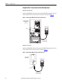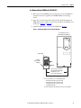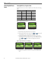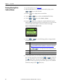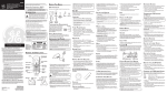
1
User Manual
PowerFlex 20-HIM-A6 / -C6S HIM (Human Interface Module)
FRN 1.xxx - 2.xxx
Important User Information
Solid-state equipment has operational characteristics differing from those of electromechanical equipment. Safety
Guidelines for the Application, Installation and Maintenance of Solid State Controls (publication SGI-1.1 available from
your local Rockwell Automation sales office or online at http://www.rockwellautomation.com/literature/) describes some
important differences between solid-state equipment and hard-wired electromechanical devices. Because of this difference,
and also because of the wide variety of uses for solid-state equipment, all persons responsible for applying this equipment
must satisfy themselves that each intended application of this equipment is acceptable.
In no event will Rockwell Automation, Inc. be responsible or liable for indirect or consequential damages resulting from the
use or application of this equipment.
The examples and diagrams in this manual are included solely for illustrative purposes. Because of the many variables and
requirements associated with any particular installation, Rockwell Automation, Inc. cannot assume responsibility or
liability for actual use based on the examples and diagrams.
No patent liability is assumed by Rockwell Automation, Inc. with respect to use of information, circuits, equipment, or
software described in this manual.
Reproduction of the contents of this manual, in whole or in part, without written permission of Rockwell Automation,
Inc., is prohibited.
Throughout this manual, when necessary, we use notes to make you aware of safety considerations.
WARNING: Identifies information about practices or circumstances that can cause an explosion in a hazardous environment,
which may lead to personal injury or death, property damage, or economic loss.
ATTENTION: Identifies information about practices or circumstances that can lead to personal injury or death, property
damage, or economic loss. Attentions help you identify a hazard, avoid a hazard, and recognize the consequence.
SHOCK HAZARD: Labels may be on or inside the equipment, for example, a drive or motor, to alert people that dangerous
voltage may be present.
BURN HAZARD: Labels may be on or inside the equipment, for example, a drive or motor, to alert people that surfaces may
reach dangerous temperatures.
IMPORTANT
Identifies information that is critical for successful application and understanding of the product.
Allen-Bradley, Rockwell Software, Rockwell Automation, and TechConnect are trademarks of Rockwell Automation, Inc.
Trademarks not belonging to Rockwell Automation are property of their respective companies.
Summary of Changes
This manual contains new and updated information.
New and Updated
Information
This table contains the changes made to this manual, which were the result of
HIM firmware revision 2.001.
Topic
Page
In Chapter 3:
• Added the Status Bar element “DLX” to indicate that the Host Drive DeviceLogix feature is enabled.
• Added new soft key labels “ACK,” “PGDN,” and “PGUP” on the Device Version information screen to
enhance navigation.
24
25
In Chapter 4:
• Changed the Fault Display screen flash mode default from “Flash Bklite” to “”Flash Status.”
• Added a TIP statement that holding the or soft key while using the Direct Parameter Access
method to view/edit a parameter provides continuous scrolling until the key is released.
• Revised Example Device Version Information Screen (Figure 38) to show the added soft key labels “Top,”
“End,” “PGUP,” and “PGDN.”
In Appendix B, changed the default for Parameter 04 - [Fault Dspy Type] from “0” (Flash Bklite) to “1” (Flash
Status).
Rockwell Automation Publication 20HIM-UM001C-EN-P - January 2012
40
42
47
65
3
Summary of Changes
Notes:
4
Rockwell Automation Publication 20HIM-UM001C-EN-P - January 2012
Table of Contents
Preface
Additional Resources . . . . . . . . . . . . . . . . . . . . . . . . . . . . . . . . . . . . . . . . . . . . . . 9
Rockwell Automation Support . . . . . . . . . . . . . . . . . . . . . . . . . . . . . . . . . . . . 10
Local Product Support . . . . . . . . . . . . . . . . . . . . . . . . . . . . . . . . . . . . . . . . 10
Technical Product Assistance. . . . . . . . . . . . . . . . . . . . . . . . . . . . . . . . . . 10
Conventions Used in This Manual . . . . . . . . . . . . . . . . . . . . . . . . . . . . . . . . 10
Chapter 1
Getting Started
HIM Types . . . . . . . . . . . . . . . . . . . . . . . . . . . . . . . . . . . . . . . . . . . . . . . . . . . . . .
Features . . . . . . . . . . . . . . . . . . . . . . . . . . . . . . . . . . . . . . . . . . . . . . . . . . . . . . . . .
Compatible Products . . . . . . . . . . . . . . . . . . . . . . . . . . . . . . . . . . . . . . . . . . . . .
Safety Precautions . . . . . . . . . . . . . . . . . . . . . . . . . . . . . . . . . . . . . . . . . . . . . . . .
11
11
12
12
Chapter 2
Installing the HIM
Installing the 20-HIM-A6 HIM . . . . . . . . . . . . . . . . . . . . . . . . . . . . . . . . . . .
In the Drive HIM Bezel . . . . . . . . . . . . . . . . . . . . . . . . . . . . . . . . . . . . . . .
Using Drive Port 2 Connection for Hand-Held Operation . . . . . .
In a Remote-Mount HIM Bezel (20-HIM-B1). . . . . . . . . . . . . . . . . .
Installing the 20-HIM-C6S HIM. . . . . . . . . . . . . . . . . . . . . . . . . . . . . . . . . .
Removing the HIM . . . . . . . . . . . . . . . . . . . . . . . . . . . . . . . . . . . . . . . . . . . . . .
14
14
16
17
18
20
Chapter 3
HIM Components
HIM Keypad . . . . . . . . . . . . . . . . . . . . . . . . . . . . . . . . . . . . . . . . . . . . . . . . . . . .
Soft Keys . . . . . . . . . . . . . . . . . . . . . . . . . . . . . . . . . . . . . . . . . . . . . . . . . . . .
Navigation and Number Keys . . . . . . . . . . . . . . . . . . . . . . . . . . . . . . . . .
Single Function Keys . . . . . . . . . . . . . . . . . . . . . . . . . . . . . . . . . . . . . . . . .
LCD Display Elements . . . . . . . . . . . . . . . . . . . . . . . . . . . . . . . . . . . . . . . . . . .
Status Bar . . . . . . . . . . . . . . . . . . . . . . . . . . . . . . . . . . . . . . . . . . . . . . . . . . . .
Data Area . . . . . . . . . . . . . . . . . . . . . . . . . . . . . . . . . . . . . . . . . . . . . . . . . . . .
Soft Key Labels . . . . . . . . . . . . . . . . . . . . . . . . . . . . . . . . . . . . . . . . . . . . . . .
Main Screens . . . . . . . . . . . . . . . . . . . . . . . . . . . . . . . . . . . . . . . . . . . . . . . . . . . .
Status Screen . . . . . . . . . . . . . . . . . . . . . . . . . . . . . . . . . . . . . . . . . . . . . . . . .
Process Screen. . . . . . . . . . . . . . . . . . . . . . . . . . . . . . . . . . . . . . . . . . . . . . . .
Control Screen . . . . . . . . . . . . . . . . . . . . . . . . . . . . . . . . . . . . . . . . . . . . . . .
Folder Screens. . . . . . . . . . . . . . . . . . . . . . . . . . . . . . . . . . . . . . . . . . . . . . . .
Fault Display Screen . . . . . . . . . . . . . . . . . . . . . . . . . . . . . . . . . . . . . . . . . .
Rockwell Automation Publication 20HIM-UM001C-EN-P - January 2012
21
21
22
23
24
24
24
25
26
26
27
28
29
30
5
Table of Contents
Chapter 4
Using the HIM
6
Initial HIM Operation on New Drive Power-Up . . . . . . . . . . . . . . . . . . .
Selecting Display Contrast . . . . . . . . . . . . . . . . . . . . . . . . . . . . . . . . . . . . . . . .
Setting the Date/Time for the Drive
(only PowerFlex 750-Series Drives) . . . . . . . . . . . . . . . . . . . . . . . . . .
Creating a User-Defined Drive/Peripheral Name . . . . . . . . . . . . . . . . . . .
Customizing the Process Screen . . . . . . . . . . . . . . . . . . . . . . . . . . . . . . . . . . .
Selecting Multi-Line or Single-Line View . . . . . . . . . . . . . . . . . . . . . . .
Changing Displayed Items, Adding a
Scale Factor or Customizing Text . . . . . . . . . . . . . . . . . . . . . . . .
Resetting the Drive/Peripherals . . . . . . . . . . . . . . . . . . . . . . . . . . . . . . . . . . .
Setting Factory Defaults . . . . . . . . . . . . . . . . . . . . . . . . . . . . . . . . . . . . . . . . . .
Setting PowerFlex 750-Series Drives/Peripherals
to Factory Defaults. . . . . . . . . . . . . . . . . . . . . . . . . . . . . . . . . . . . . .
Setting PowerFlex 7-Class Drives/Peripherals
to Factory Defaults. . . . . . . . . . . . . . . . . . . . . . . . . . . . . . . . . . . . . .
Setting Display Flashing for Fault Indication . . . . . . . . . . . . . . . . . . . . . . .
Setting Display Flashing for Alarm Indication . . . . . . . . . . . . . . . . . . . . . .
Viewing/Editing Drive or Peripheral Parameters . . . . . . . . . . . . . . . . . . . .
Selecting File-Group-Parameter or Linear List View . . . . . . . . . . . . .
Direct Parameter Access . . . . . . . . . . . . . . . . . . . . . . . . . . . . . . . . . . . . . .
Alternate Linear List Access . . . . . . . . . . . . . . . . . . . . . . . . . . . . . . . . . . .
Viewing/Clearing Drive Faults or Alarms . . . . . . . . . . . . . . . . . . . . . . . . . .
Viewing Peripheral Diagnostic Items. . . . . . . . . . . . . . . . . . . . . . . . . . . . . . .
Viewing/Clearing Peripheral Events . . . . . . . . . . . . . . . . . . . . . . . . . . . . . . .
Checking Drive and Peripheral Firmware Versions. . . . . . . . . . . . . . . . . .
Using the CopyCat Function . . . . . . . . . . . . . . . . . . . . . . . . . . . . . . . . . . . . .
Creating CopyCat Files . . . . . . . . . . . . . . . . . . . . . . . . . . . . . . . . . . . . . . .
Renaming CopyCat Files. . . . . . . . . . . . . . . . . . . . . . . . . . . . . . . . . . . . . .
Deleting CopyCat Files . . . . . . . . . . . . . . . . . . . . . . . . . . . . . . . . . . . . . . .
Changing PowerFlex 750-Series Drive Parameter Associations . . . . . . .
Using Individual Screen Entry Method . . . . . . . . . . . . . . . . . . . . . . . . .
Using Direct Numeric Entry Method . . . . . . . . . . . . . . . . . . . . . . . . . .
Linking Parameters in PowerFlex 700/700S Drives . . . . . . . . . . . . . . . . .
Establishing a Link . . . . . . . . . . . . . . . . . . . . . . . . . . . . . . . . . . . . . . . . . . .
Deleting an Established Link . . . . . . . . . . . . . . . . . . . . . . . . . . . . . . . . . .
Using a Password. . . . . . . . . . . . . . . . . . . . . . . . . . . . . . . . . . . . . . . . . . . . . . . . .
Setting/Changing the Password. . . . . . . . . . . . . . . . . . . . . . . . . . . . . . . .
Changing Password-Protected Drive/Peripheral Parameters . . . . .
Disabling Password Protection. . . . . . . . . . . . . . . . . . . . . . . . . . . . . . . . .
Initiating Port Verification (only PowerFlex 750-Series Drives) . . . . . .
When All Conflicts are “Changed” or “Requires Configuration” .
When Conflict Is “Not Functioning,” “Not Supported,”
and/or “Invalid Duplicate”. . . . . . . . . . . . . . . . . . . . . . . . . . . . . . .
Changing Language for the Display Text . . . . . . . . . . . . . . . . . . . . . . . . . . .
Flash Updating the HIM (Firmware or Language) . . . . . . . . . . . . . . . . . .
Rockwell Automation Publication 20HIM-UM001C-EN-P - January 2012
31
32
33
35
36
36
37
38
38
38
39
40
41
42
42
42
43
44
45
46
47
48
48
49
51
52
52
54
55
55
56
57
57
58
59
60
60
61
62
62
Table of Contents
Appendix A
Specifications
Communications. . . . . . . . . . . . . . . . . . . . . . . . . . . . . . . . . . . . . . . . . . . . . . . . .
Electrical . . . . . . . . . . . . . . . . . . . . . . . . . . . . . . . . . . . . . . . . . . . . . . . . . . . . . . . .
Mechanical . . . . . . . . . . . . . . . . . . . . . . . . . . . . . . . . . . . . . . . . . . . . . . . . . . . . . .
Environmental . . . . . . . . . . . . . . . . . . . . . . . . . . . . . . . . . . . . . . . . . . . . . . . . . . .
Regulatory Compliance . . . . . . . . . . . . . . . . . . . . . . . . . . . . . . . . . . . . . . . . . . .
63
63
63
63
64
Appendix B
HIM Parameters
About Parameter Numbers. . . . . . . . . . . . . . . . . . . . . . . . . . . . . . . . . . . . . . . . 65
Parameter List . . . . . . . . . . . . . . . . . . . . . . . . . . . . . . . . . . . . . . . . . . . . . . . . . . . 65
Appendix C
History of Changes
20HIM-UM001B-EN-P, October 2010 . . . . . . . . . . . . . . . . . . . . . . . . . . . 67
20HIM-UM001A-EN-P, January 2009 . . . . . . . . . . . . . . . . . . . . . . . . . . . . 67
Index
Rockwell Automation Publication 20HIM-UM001C-EN-P - January 2012
7
Table of Contents
8
Rockwell Automation Publication 20HIM-UM001C-EN-P - January 2012
Preface
Additional Resources
For…
See…
Publication
PowerFlex® 750-Series AC Drive
PowerFlex 750-Series AC Drive Installation Instructions
PowerFlex 750-Series AC Drives Programming Manual
750-IN001
750-PM001
PowerFlex® 70/70EC Drive
PowerFlex 70 User Manual
PowerFlex 70/700 Reference Manual
PowerFlex 70EC/700VC Reference Manual
20A-UM001
PFLEX-RM001
PFLEX-RM004
PowerFlex® 700/700VC Series A Drive
PowerFlex® 700VC Series B Drive
PowerFlex 700 Series A User Manual
PowerFlex 700 Series B User Manual
PowerFlex 70/700 Reference Manual
PowerFlex 70EC/700VC Reference Manual
20B-UM001
20B-UM002
PFLEX-RM001
PFLEX-RM004
PowerFlex® 700H Drive
PowerFlex 700H Installation Instructions
PowerFlex 700H Programming Manual
PFLEX-IN006
20C-PM001
PowerFlex® 700S Drive
PowerFlex 700S with Phase I Control Installation Manual (Frames 1…6)
PowerFlex 700S with Phase I Control Installation Manual (Frames 9 and 10)
PowerFlex 700S with Phase I Control User Manual (All Frames)
PowerFlex 700S with Phase I Control Reference Manual
PowerFlex 700S with Phase II Control Installation Manual (Frames 1…6)
PowerFlex 700S with Phase II Control Installation Manual (Frames 9…14)
PowerFlex 700S with Phase II Control Programming Manual (All Frames)
PowerFlex 700S with Phase II Control Reference Manual
20D-IN024
PFLEX-IN006
20D-UM001
PFLEX-RM002
20D-IN024
PFLEX-IN006
20D-PM001
PFLEX-RM003
PowerFlex® 700L Drive
PowerFlex 700L User Manual
20L-UM001
PowerFlex® Digital DC Drive
PowerFlex Digital DC Drive User Manual
20P-UM001
You can view or download publications at http://
literature.rockwellautomation.com. To order paper copies of technical
documentation, contact your local Rockwell Automation distributor or sales
representative.
To find your local Rockwell Automation distributor or sales representative, visit
www.rockwellautomation.com/locations.
For information such as firmware updates or answers to drive-related questions,
go to the Drives Service & Support web site at www.ab.com/support/abdrives
and click on the “Downloads” or “Knowledgebase” link.
Rockwell Automation Publication 20HIM-UM001C-EN-P - January 2012
9
Preface
Rockwell Automation
Support
Rockwell Automation, Inc. offers support services worldwide, with over 75 sales/
support offices, over 500 authorized distributors, and over 250 authorized
systems integrators located through the United States alone. In addition,
Rockwell Automation, Inc. representatives are in every major country in the
world.
Local Product Support
Contact your local Rockwell Automation, Inc. representative for:
• Sales and order support
• Product technical training
• Warranty support
• Support service agreements
Technical Product Assistance
For technical assistance, please review the information in Chapter 4, Using the
HIM, first. If you still have problems, then access the Allen-Bradley Technical
Support web site at www.ab.com/support/abdrives or contact Rockwell
Automation, Inc.
Conventions Used in This
Manual
This manual provides information about the enhanced PowerFlex 20-HIM-A6
and 20-HIM-C6S Human Interface Modules, and using them with PowerFlex
750-Series drives and PowerFlex 7-Class drives.
The following conventions are used throughout this manual:
• Parameter names are shown in the format Parameter xx - [*]. The xx
represents the parameter number. The * represents the parameter name—
for example Parameter 01 - [Port Number].
• Menu commands are shown in bold type face and follow the format Menu
> Command. For example, if you read “Select File > Open,” you should
click the File menu and then click the Open command.
• The firmware release is displayed as FRN X.xxx. The “FRN” signifies
Firmware Release Number. The “X” is the major release number. The
“xxx” is the minor update number.
10
Rockwell Automation Publication 20HIM-UM001C-EN-P - January 2012
Chapter
1
Getting Started
The enhanced PowerFlex 20-HIM-A6 or 20-HIM-C6S HIM provides a
communications interface to configure and monitor a PowerFlex 7-Class drive
and its connected peripherals.
Topic
HIM Types
Features
Compatible Products
Safety Precautions
HIM Types
Page
11
11
12
12
At the time of publication, these enhanced PowerFlex 7-Class HIMs are
available:
HIM Catalog Number
Description
20-HIM-A6 (1)
NEMA Type 1 HIM
20-HIM-C6S (1)
Remote-Mount NEMA Type 4X/12 HIM
(1) Supports English, Portuguese, French, Italian, German, Spanish, and Dutch
languages. The HIM can be flash updated in the field to support other available
languages. However, the language selected for download at the Rockwell
Automation Web Updates web site (www.ab.com/support/abdrives/webupdate)
will replace all other supported languages—except English, which will always
remain as the default language.
Features
When compared to the basic PowerFlex 7-Class HIM (20-HIM-A3 and -A5),
the PowerFlex 20-HIM-A6 / -C6S HIM provides these benefits:
• Full-numeric keypad with fully-integrated navigation capability to more
easily configure and monitor the drive and its connected peripherals.
• Better keypad touch response and improved tactile feel to provide more
gratifying, error-free data entry.
• More intuitive access and new menu structures that increase HIM
operating efficiency.
• Simplified custom name assignments for drive/peripherals (for example,
Pump 1) to reduce required key presses.
• Support for English, and customary European and Asian languages.
Rockwell Automation Publication 20HIM-UM001C-EN-P - January 2012
11
Chapter 1
Getting Started
• Dynamic soft keys that change functions/names based on screen or data
entry mode to reduce keypad keys and simplify HIM operation.
• Customizable drive monitoring items that can be displayed as a list on the
process screen or as individual screens.
• New flashing LCD screen to provide enhanced visibility when faults or
alarms are detected.
Compatible Products
At the time of publication, compatible products include:
•
•
•
•
•
•
•
•
•
•
Safety Precautions
PowerFlex 750-Series drives
PowerFlex 70/70EC drives
PowerFlex 700/700VC drives
PowerFlex 700H drives
PowerFlex 700S drives
PowerFlex 700L drives
PowerFlex 700AFE (Active Front End)
PowerFlex Digital DC drives
PowerFlex 7000 drives
SMC™ Flex
Please read the following safety precautions carefully.
ATTENTION: Risk of injury or death exists from machine motion when using the
HIM to Start/Stop/Jog or configure the drive.
ATTENTION: Risk of injury or equipment damage exists. Only personnel familiar
with drive and power products and the associated machinery should plan or
implement the installation, start-up, configuration, and subsequent
maintenance of the product using the HIM. Failure to comply may result in injury
and/or equipment damage.
12
Rockwell Automation Publication 20HIM-UM001C-EN-P - January 2012
Chapter
2
Installing the HIM
This chapter provides instructions for installing and removing the HIM.
Topic
Installing the 20-HIM-A6 HIM
Installing the 20-HIM-C6S HIM
Removing the HIM
Page
14
18
20
There are two types of enhanced PowerFlex 7-Class HIM:
• NEMA Type 1 (20-HIM-A6)
• Remote-mount NEMA Type 4X/12 (20-HIM-C6S), which also includes
a 1202-C30 interface cable for connection to the drive
20-HIM-A6 HIM
20-HIM-C6S HIM
Rockwell Automation Publication 20HIM-UM001C-EN-P - January 2012
13
Chapter 2
Installing the HIM
Installing the 20-HIM-A6 HIM
The 20-HIM-A6 (NEMA Type 1) HIM is normally installed in the HIM bezel
(drive Port 1) on the front of the drive. For temporary hand-held operation, the
HIM can be plugged into drive Port 2 (near the bottom of the drive control pod
for PowerFlex 750-Series drives, or on the bottom of the drive for PowerFlex 7Class drives) using a 1 m/3.28 ft. long 20-HIM-H10 cable. For applications
requiring the HIM to be located remotely, the HIM can be installed in a remotemount HIM bezel (20-HIM-B1) in a suitable location. The 20-HIM-B1
includes a 3 m/9.8 ft. long 1202-C30 cable.
In the Drive HIM Bezel
PowerFlex 750-Series IP20, NEMA/UL Open Type Drives
Place the HIM into the drive HIM bezel by inserting it straight back into the top
of the bezel and then sliding it down into the base of the bezel onto the mating
connector (Figure 1).
TIP
The HIM can be installed in the drive HIM bezel with the drive powered or
unpowered.
Figure 1 - Installing the HIM in the Drive HIM Bezel
20-HIM-A6 HIM
➋ DOWN
➊ IN
Drive HIM Bezel
(PowerFlex 755 drive shown)
14
Rockwell Automation Publication 20HIM-UM001C-EN-P - January 2012
Installing the HIM
Chapter 2
PowerFlex 750-Series IP54, NEMA/UL Type 12 Drives
1. Using the following recommended tools, unfasten and remove the cover as
shown in Figure 2:
• Screwdriver: 6.4 mm (0.25 in.) flat or T20 Hexalobular
• Hex socket: 7 mm
Figure 2 - Removing IP54, NEMA/UL Type 12 Drive Cover
2x:
M4 x 0.7
2. Place the HIM into the drive HIM bezel by inserting it straight back into
the top of the bezel and then sliding it down into the base of the bezel onto
the mating connector (see Figure 1).
3. Replace the cover and the fasteners. Tighten all screws and nuts to the
recommended torque of 0.68 N•m (6.0 lb•in).
Rockwell Automation Publication 20HIM-UM001C-EN-P - January 2012
15
Chapter 2
Installing the HIM
Using Drive Port 2 Connection for Hand-Held Operation
PowerFlex 750-Series Drive
Attach a 20-HIM-H10 cable to the bottom of the HIM. Then plug the other end
of the cable into Port 2 near the bottom of the drive control pod (Figure 3).
Figure 3 - Connecting the HIM to PowerFlex 750-Series Drive Port 2
(PowerFlex 755 drive
shown with cover
removed)
20-HIM-A6 HIM
Port 2
PE
PE
20-HIM-H10 Cable
(1 m/3.28 ft. long)
PowerFlex 7-Class Drive
Attach a 20-HIM-H10 cable to the bottom of the HIM. Then plug the other end
of the cable into Port 2 on the bottom of the drive (Figure 4).
Figure 4 - Connecting the HIM to PowerFlex 7-Class Drive Port 2
(PowerFlex 70
drive shown)
20-HIM-A6 HIM
Port 2
20-HIM-H10 Cable
(1 m/3.28 ft. long)
16
Rockwell Automation Publication 20HIM-UM001C-EN-P - January 2012
Installing the HIM
Chapter 2
In a Remote-Mount HIM Bezel (20-HIM-B1)
1. If the remote-mount HIM bezel is not mounted, refer to the HIM Bezel
Installation Instructions (publication 20HIM-IN002) for mounting
details.
2. Route the 3 m/9.8 ft. long 1202-C30 bezel cable (included with the 20HIM-B1 bezel) to the drive. Connect the bezel cable to the DPI Port 2 on
the drive (see Figure 3 or Figure 4).
3. Install the HIM into the remote-mount HIM bezel (Figure 5).
Figure 5 - Installing the HIM in a Remote-Mount HIM Bezel
PowerFlex 755 drive shown
(without HIM in drive HIM bezel)
20-HIM-A6 HIM
20-HIM-B1
Remote-Mount
HIM Bezel
➊ IN
➋ DOWN
3 m/9.8 ft. long 1202-C30 Bezel
Cable included with 20-HIM-B1
bezel. Distances can be
increased up to 75 m/246 ft. (1)
(1)
To increase this distance, use one of the following cables:
•
•
•
•
1202-H03 Extension cable (0.3 m/0.98 ft. long)
1202-H13 Extension cable (1.0 m/3.28 ft. long)
1202-H30 Extension cable (3.0 m/9.8 ft. long)
1202-CBL-KIT-100M cable
Note that a cable distance greater than 30 m/98.4 ft. is not CE compliant.
Rockwell Automation Publication 20HIM-UM001C-EN-P - January 2012
17
Chapter 2
Installing the HIM
Installing the 20-HIM-C6S
HIM
The 20-HIM-C6S (NEMA Type 4X/12) HIM is designed for remote
installation and includes a 3 m/9.8 ft. long 1202-C30 cable. Refer to Figure 6 for
overall HIM dimensions. Choose an appropriate location to mount the 20-HIMC6S HIM. The distance between the HIM and drive can be increased up to 75
m/246 ft. by using a 1202-Hxx extension cable or 1202-CBL-KIT-100M cable
kit. However, a cable distance greater than 30 m/98.4 ft. is not CE compliant.
Figure 6 - 20-HIM-C6S HIM Dimensions
Dimensions are in millimeters and (inches).
93.0
(3.66)
25.0
(0.98)
3.0 m/9.8 ft. long
1202-C30 cable
(included with
20-HIM-C6S HIM)
1202-Hxx Extension Cable
(supplied separately, and only
needed if required distance
exceeds 1202-C30 Cable length)
180.0
(7.08)
1202-H03 = 0.3 m/0.98 ft. long
1202-H10 = 1.0 m/3.28 ft. long
1202-H30 = 3.0 m/9.80 ft. long
1. Drill the required hole pattern in the panel. See Figure 7 for dimensions.
TIP
18
A conversion template (p/n 336745-C01), provided with the 20-HIMC6S HIM, includes a drilling pattern and mounting instructions to
assist HIM installation.
Rockwell Automation Publication 20HIM-UM001C-EN-P - January 2012
Installing the HIM
Chapter 2
Figure 7 - Hole Pattern to Mount the 20-HIM-C6S HIM
Dimensions are in millimeters and (inches).
67.0
(2.63)
60.0
(2.36)
Front View
77.0
(3.03)
Ø 19.1
(0.75)
59
(2.32)
77.0
(3.03)
Ø 4.8
(0.19)
2. Peel the protective film from the gasketed surface on the back of the HIM
(Figure 8).
IMPORTANT
Adhesive coated gasket is designed for one-time only installation.
Figure 8 - Mounting the 20-HIM-C6S HIM onto the Panel
➋
➎
➌
➍
0.68 N•m
➏ (6.0 lb•in)
Rockwell Automation Publication 20HIM-UM001C-EN-P - January 2012
19
Chapter 2
Installing the HIM
3. Insert the supplied 3 m/9.8 ft. long 1202-C30 HIM cable into the mating
socket on the back of the HIM.
4. Install the supplied O-ring into the cable routing hole on the panel to
protect the cable. Then route the HIM cable through the cable routing
hole on the panel.
5. Align the six threaded studs of the HIM with the panel clearance holes,
and place the HIM against the panel.
6. Tighten the nuts onto the six threaded studs of the HIM extending behind
the panel. Recommended torque is 0.68 N•m (6.0 lb•in).
7. Route the HIM cable to the drive. Connect the HIM cable to the DPI
Port 2 on the drive (see Figure 3 or Figure 4).
Removing the HIM
ATTENTION: Risk of injury or equipment damage exists. If the HIM cable or
remote-mount HIM bezel cable is disconnected from DPI Port 2 on the drive, the
drive may fault. Determine how the drive will respond before disconnecting the
cable.
IMPORTANT
The Host Drive can remain powered when removing the HIM. However, a fault
will occur if the HIM is not the last controlling device and does not have Manual
control of the Host Drive. To avoid a fault in this case, access the HIM Control
key, and then remove the HIM from the
screen (Figure 18), press the
Host Drive.
Remove the HIM from the drive HIM bezel or the remote-mount HIM bezel in
reverse order of how it was installed.
20
Rockwell Automation Publication 20HIM-UM001C-EN-P - January 2012
Chapter
3
HIM Components
This chapter describes the components of the HIM.
Topic
HIM Keypad
LCD Display Elements
Main Screens
HIM Keypad
Page
21
24
26
Soft Keys
Up to five dynamic soft keys (shown shaded in Figure 9) can be shown at the
bottom of the HIM screen. Based on the specific screen or the data entry mode
being used, a soft key name and its function may change. When a soft key is active,
its present function and corresponding Soft Key Label (Figure 12) is shown at the
bottom of the HIM screen. For a list of the soft keys, and their names and
functions, see Soft Key Labels on page 25.
Figure 9 - Soft Keys
Rockwell Automation Publication 20HIM-UM001C-EN-P - January 2012
21
Chapter 3
HIM Components
Navigation and Number Keys
The five blue multi-function keys (2, 4, 5, 6, and 8) shown in Figure 10 are used to:
• Enter their respective numeric value
• Scroll menus/screens
• Perform corresponding functions displayed in the Data Area (see page 24)
The five gray number keys (0, 1, 3, 7, and 9) are used only to enter their respective
numeric value.
Figure 10 - Navigation and Number Keys
Key
22
Name
Function
2/Down Arrow
• Enters the numeric value “2.”
• Scrolls down to select an item.
4/Left Arrow
• Enters the numeric value “4.”
• Scrolls left to select an item.
5/Enter
•
•
•
•
6/Right Arrow
• Enters the numeric value “6.”
• Scrolls right to select an item.
8/Up Arrow
• Enters the numeric value “8.”
• Scrolls up to select an item.
Enters the numeric value “5.”
Displays the next level of a selected menu item.
Enters new values.
Performs intended actions.
Rockwell Automation Publication 20HIM-UM001C-EN-P - January 2012
HIM Components
Chapter 3
Single Function Keys
The four single-function keys shown in Figure 11 and listed in the table below
always perform only their dedicated functions.
Figure 11 - Single Function Keys
Key
Name
Function
Start
Starts the drive.
(1)
Folders
Accesses folders for parameters, diagnostics, memory functions,
preferences, and other tasks.
(1)
Controls
Accesses jog, direction, auto/manual, and other control functions.
Stop
• Stops the drive or clears a fault.
• This key is always active.
• This key is controlled by drive parameter 307 [Start Stop Mode].
(1) During drive Start Up these keys are temporarily inactive.
Rockwell Automation Publication 20HIM-UM001C-EN-P - January 2012
23
Chapter 3
HIM Components
LCD Display Elements
The basic HIM screen is divided into three display zones (Figure 12). Each
display zone is described below in its respective subsection.
Figure 12 - HIM Display Zones
Stopped
0.00 Hz
00
ESC
AUTO
F
Status Bar
Host Drive
240V
4.2A
20G...D014
REF
Data Area
PAR# TEXT
Soft Key Labels
Status Bar
The Status Bar provides operating status information about the Host Drive.
Figure 13 - Status Bar on the Display Screen
Stopped
0.00 Hz
AUTO
F
Element
Meaning
Host Icon
A small image of the connected Host Drive.
Stopped
Status Text
Indicates current Host Drive operating status.
Text flashes when a fault is present.
0.00 Hz
Feedback
Indicates drive output feedback (for example, Hz, RPM, amps, etc.)
AUTO/MAN
Mode Indication
Indicates Auto or Manual HIM status.
Alarm Indication
Bell icon indicates that an alarm is present.
F R
Rotation Indication
Indicates Forward or Reverse direction of Host Drive operation.
DLX (not shown)
DeviceLogix Indication
Indicates when the Host Drive DeviceLogix feature is enabled.
Data Area
The Data Area displays the data or function presently being acted upon.
Figure 14 - Data Area on the Display Screen
Host Drive
240V
4.2A
20G...D014
00
Element
24
Meaning
Host or Device Icon
Image of the Host Drive or image of the device connected to the port
selected.
00 Port Selection
Indicates selected port. Use the
select a port.
Host Drive
User-Definable Text
Top line of text in the Data Area can be edited by the user.
Rockwell Automation Publication 20HIM-UM001C-EN-P - January 2012
or
navigation keys to
HIM Components
Chapter 3
Soft Key Labels
The Soft Key Labels identify the present function of a corresponding Soft Key on
the Key Pad. Different screens may show different Soft Key Labels.
Figure 15 - Soft Key Labels Example on the Display Screen
ESC
VIEW
REF
PAR# TEXT
Soft Key Labels
Soft Keys
Label
Name
Function
.
Decimal Point
Adds decimal point to the right-most position of a numeric value.
Backspace
Deletes the character to the left of the cursor.
+ / -
Sign
Changes the sign of a parameter value.
#
Number
Selects the Direct Numeric Entry Method to change PowerFlex 750-Series drive parameter associations.
Language
Directly accesses the Select Language To Use screen.
Scroll Up
• Scrolls up through display lines.
• Increases a value.
Scroll Down
• Scrolls down through display lines.
• Decreases a value.
Scroll Left
Scrolls left through display lines.
Scroll Right
Scrolls right through display lines.
ACK
Acknowledge
Acknowledges the fault or alarm on the pop-up screen, stops the backlight from flashing, and keeps the
pop-up screen active.
ALL
All
• Clears all faults, alarms or events when a pop-up box appears from a queue screen.
• Restores all Host or Port device parameters to factory defaults.
CLR
Clear
• Deletes an entire text string.
• Displays the Select Action pop-up box used to clear the selected fault, alarm or event, or the entire
fault, alarm or event queue.
DEL
Delete
Deletes a highlighted character.
EDIT
Edit
• Accesses a displayed parameter to edit.
• Accesses the Edit Process Display screen.
END
End
• Displays the end (least recent) fault, alarm or event in a queue
• Scrolls to the end line of data on the Device Version information screen.
ENTER
Enter
• Displays the next level of a selected menu item.
• Enters new values.
• Performs the intended action.
ESC
Escape
•
•
•
•
•
EXP
Exponent
Allows data entry using scientific notation for 32-bit REAL (floating point) values.
FIX
Fix
Fixes “Changed” or “Requires Configuration” port verification conflicts upon power up.
INFO
Information
• Shows additional information about a selected port verification conflict upon power up.
• Shows additional information about Set Default actions.
INS
Insert
Inserts a space to the left of a highlighted character.
Cancels port verification conflict pop-up box during procedure to resolve a conflict.
Cancels the existing screen and returns to the previous screen.
Cancels an entry.
Cancels pop-up Fault Display screen.
Displays the time zone groups list screen (only when the Date/Time Set Edit Mode screen is shown).
Rockwell Automation Publication 20HIM-UM001C-EN-P - January 2012
25
Chapter 3
HIM Components
Main Screens
Label
Name
Function
LINK
Link
Displays a Link Edit pop-up box to link parameters (PowerFlex 7-Class drives only).
LOWER
Lower
Displays the lower 16 bits (bits 0…15) of a 32-bit Bit-type parameter.
MOST
Most
Restores most Host or Port device parameters to factory defaults.
PAR#
Parameter Number
Navigates directly to a parameter.
PGDN
Page Down
Scrolls down to the next page of data lines on the Device Version information screen.
PGUP
Page Up
Scrolls up to the previous page of data lines on the Device Version information screen.
REF
Reference
Enters the speed reference for the Host Drive.
RESET
Reset
Resets the Process screen’s displayed monitoring items to the factory default monitoring items listed on
page 36.
TEXT
Text
Edits user-definable text for the device selected.
TOP
Top
• Displays the top (most recent) fault, alarm or event in a queue.
• Scrolls to the top line of data on the Device Version information screen.
UPPER
Upper
Displays the upper 16 bits (bits 16…31) of a 32-bit Bit-type parameter.
VIEW
View
• Toggles between select screens and views.
• Displays the time stamp screen from a fault, alarm or event queue screen.
ZONES
Zones
Displays the Select Time Zone screen.
Status Screen
On power up, the Status screen (Figure 16) is shown by default. Depending on
the type of Host Drive, the Status screen displays the following information:
Host PowerFlex Drive
Displayed Information
750-Series
7-Class
Selected device icon and port number
✔
✔
Device name (1)
✔
✔
Rating text (volts, amps)
✔
✔
Drive catalog text
✔
n/a
Firmware version and hardware series
(2)
✔
(1) The displayed default device name is dependent on the Host drive. The device name can be
changed, for example, to Host Drive as shown in the screens below. See Creating a User-Defined
Drive/Peripheral Name on page 35 for details.
(2) The firmware version and hardware series for a PowerFlex 750-Series drive can be shown using
HIM menu screens. For details, see Checking Drive and Peripheral Firmware Versions on page 47.
Figure 16 - Example Status Screens
Stopped
0.00 Hz
00
ESC
AUTO
F
Host Drive
240V
4.2A
20G...D014
REF
PAR# TEXT
For PowerFlex 750-Series Drive
26
Stopped
0.00 Hz
00
ESC
AUTO
F
Host Drive
240V
4.2A
Rev 3.002 Ser. A
REF
PAR# TEXT
For PowerFlex 7-Class Drive
Rockwell Automation Publication 20HIM-UM001C-EN-P - January 2012
HIM Components
Chapter 3
Status Screen Soft Keys
Label
Name
Function
ESC
Escape
Toggles between the Status and Process Display screens.
Language Icon
Directly accesses the Select Language To Use screen.
REF
Reference
Enters the speed reference for the Host Drive.
PAR#
Parameter Number
Directly accesses a parameter for the device on selected port. (This soft key is
not available if the device has no parameters.)
TEXT
Text
Edits user-definable text for the device on selected port.
Status Screen Navigation/Number Keys
Key
Name
Function
4/Left Arrow
Selects the device on previous port.
6/Right Arrow
Selects the device on next port.
Screen Element
00
If you would rather see the Process screen (Figure 17) as the initial power-up
screen, change the HIM Parameter 03 - [Initial Screen] value to “1” (Process
Scrn). By default, when the HIM keys are not used for the time period set in
Parameter 07 - [User Dspy Time], the screen being displayed at that time will
revert back to the initial screen. You can disable this feature by setting Parameter
06 - [User Dspy Enable] to “1” (Disable).
Process Screen
To display the Process screen, press the ESC soft key on the Status screen
(Figure 16). The Process screen shows various drive monitoring parameters.
Multi-line and Single-line views can be selected by pressing the VIEW soft key.
The displayed default monitoring parameters can be changed. See Customizing
the Process Screen on page 36 for details.
Figure 17 - Process Screen
Stopped
0.00 Hz
AUTO
F
0.00 Amps
0.000 Bus VDC
0.00 Out Vlts
ESC
VIEW
REF
PAR# EDIT
Process Screen Soft Keys
Label
Name
Function
ESC
Escape
Toggles between the Process Display and Status screens.
VIEW
View
Toggles between the multi-line and single-line views.
REF
Reference
Enters the speed reference for the Host Drive.
PAR#
Parameter Number
Directly accesses a parameter for the selected port device.
EDIT
Edit
Directly accesses the Edit Process Display screen.
Rockwell Automation Publication 20HIM-UM001C-EN-P - January 2012
27
Chapter 3
HIM Components
Process Screen Navigation/Number Keys
Key
Name
Function
Screen Element
8/Up Arrow
Scrolls up through the display lines.
2/Down Arrow
Scrolls down through the display lines.
Control Screen
The Control screen is used to directly control the drive. It displays vertical bar
graphs of the drive’s speed Reference and Feedback values, and a Key Function
Map that corresponds to the navigation/number keys for drive control. Press the
(Controls) key to display the Control screen.
To navigate from the Control screen to another HIM menu screen, you must
always press the ESC soft key which deactivates the Control screen and displays
the previous screen.
IMPORTANT
Figure 18 - Control Screen
Stopped
0.00 Hz
REMOVE
HIM
REV REF FBK
ESC
JOG
AUTO
F
REF
EDIT
REF
REF
Control Screen Key Function Map
corresponds to Navigation/Number Keys
MANUAL
FWD
HELP
See table below
for key functions
Control Screen Soft Key
Label
Name
Function
ESC
Escape
Reverts back to the previous screen.
Control Screen Navigation/Number Keys
Label
JOG
REF
HELP
REV Function
Jogs the Host Drive.
Decreases the speed reference for the Host Drive.
Displays Rockwell Automation Drives Technical Support direct phone number, web site
address, and email address.
Sets the direction to reverse for the Host Drive.
EDIT
REF
FWD
Allows direct data entry of the speed reference for the Host Drive.
REMOVE
HIM
Allows HIM removal without causing a fault if the HIM is not the last controlling device.
(The REMOVE HIM label is not available when the HIM has manual control of the Host
Drive. In this case, a fault will occur if the HIM is removed.)
Increases the speed reference for the Host Drive.
REF
MANUAL
28
Key
Sets the direction to forward for the Host Drive.
Switches between Auto and Manual modes.
Rockwell Automation Publication 20HIM-UM001C-EN-P - January 2012
HIM Components
Chapter 3
Folder Screens
The drive and each connected peripheral has its own set of Folder screens:
Folder Screen
Description
PORTS
Displays a list of Host Drive ports to which peripherals are connected. The Host Drive is always
Port 00. An icon appears for the device occupying the selected port.
DEV PARAM
Displays a list of available methods to access the device’s parameters.
HOST PARAM (1)
Displays a list of available methods to access the Host Drive parameters.
DIAGNOSTIC
Displays a list of available diagnostic information items for the device.
MEMORY
Displays a list of available memory storage items for the device.
PROPERTIES
Displays a list of available user-defined convenience functions for the device.
START UP
Displays a list of available Host Drive start up routines. This folder is not applicable for peripheral
devices and is not shown.
(1) The HOST PARAM folder screen is only available for PowerFlex 750-Series peripherals that support use of Host Drive parameters (for
example, the 20-750-DNET DeviceNet communication Option Card).
To display the last-viewed Folder screen, press the
screen Data Area displays:
• Selected device and port number
• Host drive and peripheral folders
(Folders) key. The Folder
Figure 19 - Example Folder Screen (Device Parameters)
Stopped
0.00 Hz
AUTO
F
DEV PARAM
00
ESC
Linear List
File-Group
Changed Parameters
Param Access Level
Folder Screen Soft Key
Label
Name
Function
ESC
Escape
Reverts back to the Status or Process Display screen.
Folder Screen Navigation/Number Keys
Key
Name
Function
Screen Element
2/Down Arrow
Scrolls down through the folder items.
4/Left Arrow
Scrolls to the previous folder.
5/Enter
Displays the next level screen for a selected folder item.
Not applicable
6/Right Arrow
Scrolls to the next folder.
8/Up Arrow
Scrolls up through the folder items.
Rockwell Automation Publication 20HIM-UM001C-EN-P - January 2012
29
Chapter 3
HIM Components
Fault Display Screen
The pop-up Fault Display screen automatically appears when a fault condition is
detected for the Host Drive or any connected peripheral. The pop-up Fault
Display screen flashes to alert that a fault condition exists. This screen displays:
• Fault Code number
• Fault description
• Elapsed time (in hh:mm:ss format) from fault detection
The flash mode for the Fault Display screen can be changed. For details, refer to
Setting Display Flashing for Fault Indication on page 40.
Figure 20 - Pop-Up/Flashing Fault Display Screen
Stopped
0.00 Hz
AUTO
F
– – FAULTED – –
Fault Code 81
DPI Port1 Loss
Elapsed Time 01:26:37
ESC
CLR
Fault Display Screen Soft Keys
Label
Name
Function
ESC
Escape
Reverts back to the previous screen without clearing the fault.
CLR
Clear
Removes the pop-up Fault Display screen from the display and clears the fault.
Fault Display Screen Single Function Key
Key
30
Name
Function
Stop
Removes the pop-up Fault Display screen from the display, clears the fault, and
sends a STOP command to the Host drive.
Rockwell Automation Publication 20HIM-UM001C-EN-P - January 2012
Chapter
4
Using the HIM
This chapter provides information about using the HIM.
Topic
Initial HIM Operation on New Drive Power-Up
Selecting Display Contrast
Setting the Date/Time for the Drive (only PowerFlex 750-Series Drives)
Creating a User-Defined Drive/Peripheral Name
Customizing the Process Screen
Resetting the Drive/Peripherals
Setting Factory Defaults
Setting Display Flashing for Fault Indication
Setting Display Flashing for Alarm Indication
Viewing/Editing Drive or Peripheral Parameters
Viewing/Clearing Drive Faults or Alarms
Viewing Peripheral Diagnostic Items
Viewing/Clearing Peripheral Events
Checking Drive and Peripheral Firmware Versions
Using the CopyCat Function
Changing PowerFlex 750-Series Drive Parameter Associations
Linking Parameters in PowerFlex 700/700S Drives
Using a Password
Initiating Port Verification (only PowerFlex 750-Series Drives)
Changing Language for the Display Text
Flash Updating the HIM (Firmware or Language)
Page
31
32
33
35
36
38
38
40
41
42
44
45
46
47
48
52
55
57
60
62
62
For a list of parameters, see Appendix B, HIM Parameters.
Initial HIM Operation on New
Drive Power-Up
When powering up a new drive for the first time, the HIM runs through an
initial operating routine that:
• Prompts you to select a language.
• Initiates a drive start-up routine.
• Initiates a port verification check (for PowerFlex 750-Series drives only). If
a port conflict is detected, see page 60 for information to resolve it.
Rockwell Automation Publication 20HIM-UM001C-EN-P - January 2012
31
Chapter 4
Using the HIM
Selecting Display Contrast
The contrast of the HIM display can be adjusted for optimal viewing:
1. Access the Status screen, which is displayed on HIM power up.
Figure 21 - Status Screen
Stopped
0.00 Hz
00
ESC
AUTO
F
Host Drive
240V
4.2A
20G...D014
REF
2. Use the
connected:
PAR# TEXT
or
key to scroll to the port to which the HIM is
Port
Location
01
HIM cradle on the front of the drive.
02
DPI port near the bottom of the drive control pod (PowerFlex 750-Series drives) or
at the bottom of the drive (PowerFlex 7-Class drives).
03
Splitter cable port when the cable is plugged into the DPI port near the bottom of the drive control
pod (PowerFlex 750-Series drives) or at the bottom of the drive (PowerFlex 7-Class drives).
3. Press the
key to display its last-viewed folder.
4. Use the
or
key to scroll to the PROPERTIES folder.
5. Use the
or
6. Press the
box.
(Enter) key to display the Set LCD Contrast edit pop-up
key to select Adjust Contrast.
7. Use the or soft key to adjust contrast to the desired setting.
8. Press the ESC soft key to set the contrast and exit the screen.
32
Rockwell Automation Publication 20HIM-UM001C-EN-P - January 2012
Using the HIM
Setting the Date/Time for
the Drive (only PowerFlex
750-Series Drives)
Chapter 4
The PowerFlex 750-Series drive has a real-time clock which supports its time
stamp feature for faults and alarms. The clock must be set to provide meaningful
results. To set the date and time:
1. Access the Status screen (see Figure 21).
2. If Port 00 (Host Drive) is not shown above the ESC soft key, use the
or
key to scroll to Port 00.
3. Press the
key to display its last-viewed folder.
4. Use the
or
key to scroll to the PROPERTIES folder.
5. Use the
or
6. Press the
(Enter) key to display the Date / Time Set screen.
key to select Set Date and Time.
Figure 22 - Date / Time Set Screen
AUTO
Stopped
0.00 Hz
F
Port 00 Date / Time Set
Monday
2008/05/12
(GMT-06:00)
Chicago
10:38:47
ESC
EDIT
The top line shows the present date and time in this format:
yyyy/mm/dd
hh:mm:ss
Note that the time is always displayed in a 24-hour format. For example,
6:00 pm is shown as 18:00:00.
7. Press the EDIT soft key to access the Date / Time Set Edit Mode screen,
which highlights the present time zone line.
Figure 23 - Date / Time Set Edit Mode Screen
AUTO
Stopped
F
0.00 Hz
Port 00 Date / Time Set
Monday
2008/05/12
(GMT-06:00)
Chicago
ESC
10:38:47
ZONES
▼
8. To select the time zone:
a. Press the ZONES soft key to display the Select Time Zone screen.
b. Use the
or
key to select your time zone region (for
example, Americas). Then press the
(Enter) key to enter your
selection.
c. Use the
or
key to select your specific time zone (for
example, Chicago), and press the
Rockwell Automation Publication 20HIM-UM001C-EN-P - January 2012
(Enter) key to enter it.
33
Chapter 4
Using the HIM
9. To set the date:
a. Press the soft key to select the year in the top line, and use the
numeric keys to enter the correct year.
TIP
To delete an erroneous date (or time) entry, use the soft key. Also, a
partial or complete date (or time) value will not update until you press
the soft key to advance to another field or press the ESC soft key to
return to the previous screen.
b. Press the soft key to select the month in the top line, and use the
numeric keys to enter the correct month.
c. Press the soft key to select the day in the top line, and use the numeric
keys to enter the correct day.
10. To set the time:
a. Press the soft key to select the hour in the top line, and use the
numeric keys to enter the correct hour.
b. Press the soft key to select the minutes in the top line, and use the
numeric keys to enter the correct minute.
c. Press the soft key to select the seconds in the top line, and use the
numeric keys to enter the correct seconds.
11. Press the ESC soft key to return to the previous screen.
34
Rockwell Automation Publication 20HIM-UM001C-EN-P - January 2012
Using the HIM
Creating a User-Defined
Drive/Peripheral Name
Chapter 4
The Host Drive and each of its connected peripherals has a default name. You can
change any of these default names, but the length of each new user-defined name
cannot exceed 16 characters.
Text editing is not supported when using Asian language characters. Only
characters in the ISO 8859-1 Latin 1 Character Set, which is supported by U.S.
and European personal computers, are available. If a software tool is used for
text editing Asian characters, the HIM will replace all unsupported characters
with a [] (narrow rectangle) mark.
IMPORTANT
1. Access the Status screen (see Figure 21).
2. Use the
or
key to scroll to the Port of the device whose name
you want to change (for example, Port 00 for the Host Drive).
3. Press the TEXT soft key to display the Edit User Defined Text pop-up box.
Figure 24 - Edit User Defined Text Pop-Up Box
AUTO
Stopped
0.00 Hz
F
Edit User Defined Text
PowerFlex 755
,=Move Cursor =Char Set
ESC
INS
DEL
CLR
ENTER
4. Use the
or
key to move the cursor to the desired character
position in the displayed name.
5. Press the
key to access the last-viewed character set.
6. Press the appropriate numeric key to access the desired character set:
Numeric Key
Function
Selects the numeric character set.
Selects the symbols character set.
Selects the upper case letter character set.
Selects the lower case letter character set.
Also, use the appropriate soft keys to help create the new name.
Soft Key
Function
DEL
Deletes a highlighted character.
INS
Inserts a space to the left of a highlighted character.
CLR
Deletes an entire text string.
7. With the desired character selected in that character position, press the
key to select and enter the character.
8. Repeat steps 4 through 7 for each character position.
9. When the desired name is displayed on the edit pop-up box, press the
ENTER soft key to enter and save the new name.
Rockwell Automation Publication 20HIM-UM001C-EN-P - January 2012
35
Chapter 4
Using the HIM
Customizing the Process
Screen
Selecting Multi-Line or Single-Line View
By default, the Process screen shows a multi-line view of these drive monitoring
items:
Drive Monitoring Item
Host PowerFlex Drive
Screen Text
Description
750-Series
7-Class
Amps
Output Amps
✔
✔
Bus DC
DC Bus Volts
✔
✔
Out Vlts
Output Volts
✔
n/a
Out Pwr
Output Power
✔
n/a
Elp kWHr
Elapsed kWHr
✔
n/a
Trq Cur
Torque Current
✔
n/a
Figure 25 - Multi-Line View Process Screen
Stopped
0.00 Hz
Stopped
0.00 Hz
AUTO
F
0.00 Amps
0.000 Bus VDC
0.00 Out Vlts
ESC
VIEW
AUTO
F
0.00 Amps
0.000 Bus VDC
REF PAR# EDIT
ESC
For PowerFlex 750-Series Drive
VIEW
REF
PAR# EDIT
For PowerFlex 7-Class Drive
1. Press the ESC soft key until the Process screen appears.
2. For PowerFlex 750-Series drives only, use the
or
to the hidden line items on the multi-line view screen.
key to scroll
3. To change the multi-line view Process screen to show each of the drive
monitoring items in a larger single-line view, press the VIEW soft key. Then
use the
or
key to scroll to each single-line view Process
screen.
Figure 26 - Single-Line View Process Screen Examples
Stopped
0.00 Hz
0.00
AUTO
F
Amps
ESC
VIEW REF
PAR# EDIT
Stopped
0.00 Hz
0.000
AUTO
F
Bus VDC
ESC
VIEW REF
PAR# EDIT
Stopped
0.00 Hz
0.00
AUTO
F
Out Vlts
ESC
VIEW REF
PAR# EDIT
4. To return to the multi-line view Process screen, press the VIEW soft key
again.
36
Rockwell Automation Publication 20HIM-UM001C-EN-P - January 2012
Using the HIM
Chapter 4
Changing Displayed Items, Adding a Scale Factor or Customizing Text
You can further customize the Process screen by:
• Changing a displayed parameter to a different parameter.
• Applying a scale factor to the displayed parameter.
• Customizing text for the displayed parameter.
To do any or all of the above:
1. With either the multi-line view Process screen (Figure 25) or the singleline view Process screen (Figure 26) displayed, use the
to select the drive monitoring item you want to change.
or
key
2. Press the EDIT soft key. For example, suppose you want to change the first
drive monitoring item. In this case, the Process Display 1 Edit screen is
shown.
Figure 27 - Example Process Display 1 Edit Screen
AUTO
Stopped
0.00 Hz
F
Port 00 Proc Display 1 Param:
7
Output Current
Scale:+/- 1.00
Text:
Amps
Value:
0.00 Amps
ESC
RESET EDIT
▼
3. Use the soft key to select what you want to change (parameter, scale or
text) for the drive monitoring item.
4. Press the EDIT soft key to display its respective edit pop-up box (see
examples below).
Figure 28 - Example Process Display Edit Pop-Up Boxes
AUTO
Stopped
0.00 Hz
F
Edit Proc Dspy 1 Param
7
1
ESC
AUTO
Stopped
0.00 Hz
F
Edit Proc Dspy 1 Scale
1.00
<< 1474
0.00 << 300.00
ENTER
ESC
. AUTO
Stopped
F
0.00 Hz
Edit Proc Dspy 1 Text
Amps
,=Move Cursor =Char Set
ENTER
ESC
INS
DEL
CLR
ENTER
5. For parameter or scale editing, use the numeric keys and available soft keys.
Then press the ENTER soft key to enter and save the item.
For text editing, use the numeric keys, available soft keys, and the
key
to enter each character. Then press the ENTER soft key to enter and save
the complete text string.
Rockwell Automation Publication 20HIM-UM001C-EN-P - January 2012
37
Chapter 4
Using the HIM
Resetting the Drive/
Peripherals
The drive or any of its connected peripherals can be reset by removing and
restoring power to the drive (power cycling). If this is inconvenient or cannot be
done because of application circumstances, the HIM can be used to reset the
drive/peripherals:
1. Access the Status screen (see Figure 21).
2. Use the
or
key to scroll to the Port of the device you want to
reset (for example, Port 00 for the Host Drive).
3. Press the
key to display its last-viewed folder.
4. Use the
or
5. Use the
or
key to scroll to the DIAGNOSTIC folder.
key to select Reset Device.
6. Press the
(Enter) key to display a pop-up box asking if you want to
reset the device.
7. Press the ENTER soft key to affirm and reset the device, or press the ESC
soft key to cancel.
Setting Factory Defaults
Setting PowerFlex 750-Series Drives/Peripherals to Factory Defaults
1. Access the Status screen (see Figure 21).
2. Use the
or
key to scroll to the Port of the device whose
parameters you want to set to factory defaults (for example, Port 00 for the
Host Drive or the respective port number for one of the drive’s connected
peripherals).
3. Press the
key to display its last-viewed folder.
4. Use the
or
key to scroll to the MEMORY folder.
5. Use the
or
6. Press the
(Enter) key to display the Set Defaults pop-up box.
key to select Set Defaults.
Figure 29 - Set Defaults Pop-Up Box for PowerFlex 750-Series Drives
Stopped
0.00 Hz
Port 00 Set Defaults
AUTO
F
Host and Ports (Preferred)
This Port Only
This Port Only
ESC
ESC
INFO
For Host Drive
38
Stopped
0.00 Hz
Port xx Set Defaults
Rockwell Automation Publication 20HIM-UM001C-EN-P - January 2012
AUTO
F
INFO
For Connected Peripheral
Using the HIM
Chapter 4
7. Use the
or
key to select the appropriate action.
• Host and Ports (Preferred): Selects the Host device and all ports for a
factory default action.
• This Port Only: Selects only this port for a factory default action.
TIP
For a description of a selected menu item, press the INFO soft key.
8. Press the
defaults.
(Enter) key to display the warning pop-up box to reset
Figure 30 - Host and Ports (Preferred) Pop-Up Box
Stopped
0.00 Hz
Figure 31 - This Port Only Pop-Up Box
Stopped
0.00 Hz
AUTO
F
AUTO
F
WARNING
Sets most parameters in the
Host device and all ports
to factory defaults.
Continue?
WARNING
Use MOST to reset typical
settings on this port
(preferred). Use ALL to
reset all settings.
ESC
ESC
ENTER
Press the ENTER soft key to affirm and set most parameters
for the Host Drive and port devices to factory defaults. In this
case, refer to the Host Drive and port device User Manuals for
the settings that will NOT be restored—or press the ESC soft
key to cancel.
ALL
▲
▼
MOST
Press the MOST soft key to set MOST settings for the selected
port device to factory defaults. In this case, refer to the Host
Drive User Manual for the settings that will NOT be restored.
Press the ALL soft key to set ALL settings for the selected port
device to factory defaults—or press the ESC soft key to cancel.
Setting PowerFlex 7-Class Drives/Peripherals to Factory Defaults
1. Access the Status screen (see Figure 21).
2. Use the
or
key to scroll to the Port of the device whose
parameters you want to set to factory defaults (for example, Port 00 for the
Host Drive or the respective port number for one of the drive’s connected
peripherals).
3. Press the
key to display its last-viewed folder.
4. Use the
or
key to scroll to the MEMORY folder.
5. Use the
or
6. Press the
(Enter) key to display the Set Defaults pop-up box.
key to select Set Defaults.
Figure 32 - Set Defaults Pop-Up Box
Stopped
0.00 Hz
AUTO
F
WARNING
Sets all parameters to
factory defaults.
Continue?
ESC
ENTER
7. Press the ENTER soft key to affirm and set all device parameter values to
factory defaults—or press the ESC soft key to cancel.
Rockwell Automation Publication 20HIM-UM001C-EN-P - January 2012
39
Chapter 4
Using the HIM
Setting Display Flashing for
Fault Indication
Whenever a fault for the Host Drive or any of its connected peripherals is
detected, a pop-up Fault Display screen (Figure 20) appears. By default, only the
Status Bar flashes to alert the operator. However, you can change the flash mode
for the Fault Display screen:
• Flash Bklite; selects the entire LCD screen to flash.
• Flash Status (default); selects only the Status Bar (item 1, Figure 12) to flash.
• Flash None; selects no flashing for the Fault Display screen.
To change the flash mode:
1. Access HIM Parameter 04 - [Fault Dspy Type] using either the Direct
Parameter Access method (page 42) or Alternate Linear List method
(page 43).
2. Press the EDIT soft key to display the Edit Fault Dspy Type pop-up box.
Figure 33 - Edit Fault Dspy Type Pop-Up Box
AUTO
Stopped
0.00 Hz
F
Edit Fault Dspy Type
Flash Bklite
0
ESC
▲
<< 2
▼
0
ENTER
3. Use the and soft keys to select the desired flash mode. To delete an
erroneous entry, use the soft key.
4. Press the ENTER soft key to enter your selection and return to the
parameter screen.
40
Rockwell Automation Publication 20HIM-UM001C-EN-P - January 2012
Using the HIM
Setting Display Flashing for
Alarm Indication
Chapter 4
Whenever an alarm for the Host Drive is detected, an alarm bell icon appears in
the Status Bar. By default, only the Status Bar flashes to alert the operator.
However, you can change the flash mode for alarm indication:
• Flash Bklite; selects the entire LCD screen to flash.
• Flash Status (default); selects only the Status Bar (item 1, Figure 12) to flash.
• Flash None; selects no flashing for alarm indication.
To change the flash mode:
1. Access HIM Parameter 05 - [Alarm Dspy Type] using either the Direct
Parameter Access method (page 42) or Alternate Linear List method
(page 43).
2. Press the EDIT soft key to display the Edit Alarm Dspy Type pop-up box.
Figure 34 - Edit Alarm Dspy Type Pop-Up Box
AUTO
Stopped
F
0.00 Hz
Edit Alarm Dspy Type
Flash Status
0
ESC
▲
<< 2
▼
1
ENTER
3. Use the and soft keys to select the desired flash mode. To delete an
erroneous entry, use the soft key.
4. Press the ENTER soft key to enter your selection and return to the
parameter screen.
Rockwell Automation Publication 20HIM-UM001C-EN-P - January 2012
41
Chapter 4
Using the HIM
Viewing/Editing Drive or
Peripheral Parameters
Selecting File-Group-Parameter or Linear List View
The PowerFlex 20-HIM-A6 / -C6S HIM displays Host Drive parameters by
File-Group-Parameter view or by Linear List.
Not all peripheral devices support viewing parameters in a File-GroupParameter view.
TIP
To change viewing between File-Group-Parameter and Linear List:
1. Access the Status screen (see Figure 21).
2. Use the
or
key to scroll to the Port of the device whose
parameters you want to access (for example, Port 00 for the Host Drive).
3. Press the
key to display its last-viewed folder.
4. Use the
or
PARAM folder.
5. Use the
key to scroll to the DEV PARAM or HOST
or
key to select Linear List or File-Group.
6. Press the
(Enter) key to display the last-viewed or first parameter in
the Linear List, or the last-viewed or first parameter in the first Group.
Direct Parameter Access
1. Access the Status screen (see Figure 21).
2. Use the
or
key to scroll to the Port of the device whose
parameters you want to access (for example, Port 00 for the Host Drive).
3. Press the PAR# soft key to display the Jump to Param # entry pop-up box.
TIP
Some devices have two sets of parameters (Device and Host
parameters). In this case, a pop-up box will appear to enable you to
first choose the parameter set in which the parameter is that you want
to directly access.
4. Use the numeric keys to enter the desired parameter number, or use the or soft key to scroll to the desired parameter number.
TIP
Pressing and holding the or soft key for 1 second or longer
provides continuous scrolling until the key is released.
5. Press the ENTER soft key to display the parameter.
42
Rockwell Automation Publication 20HIM-UM001C-EN-P - January 2012
Using the HIM
Chapter 4
6. Press the EDIT soft key (for editable parameters only) to display the Edit
Parameter pop-up box.
Figure 35 - Example Edit Parameter Pop-Up Box
Stopped
0.00 Hz
AUTO
F
Edit Accel Time 1
5.0 Secs
0.00 << 3600.00
ESC
. ENTER
7. Use the numeric keys, decimal soft key, and soft key to edit the parameter.
When the decimal soft key is pressed while editing a numeric value,
this key temporarily changes to an EXP soft key to allow exponential
entry.
TIP
8. Press the ENTER soft key to enter the new parameter value and return to
the parameter screen.
Alternate Linear List Access
1. Access the Status screen (see Figure 21).
2. Use the
or
key to scroll to the Port of the device whose
parameters you want to access (for example, Port 00 for the Host Drive).
3. Press the
key to display its last-viewed folder.
4. Use the
or
key to scroll to the PARAMETER folder.
5. Use the
or
key to select Linear List.
6. Press the
(Enter) key to display either the device’s last-viewed
parameter or the first parameter in the linear list.
7. Use the
or
key to scroll to the desired parameter.
8. Press the EDIT soft key (for editable parameters only) to display the Edit
Parameter pop-up box (Figure 35).
9. Use the numeric keys, decimal soft key, and soft key to edit the parameter.
TIP
When the decimal soft key is pressed while editing a numeric value,
this key temporarily changes to an EXP soft key to allow exponential
entry.
10. Press the ENTER soft key to enter the new parameter value and return to
the parameter screen.
Rockwell Automation Publication 20HIM-UM001C-EN-P - January 2012
43
Chapter 4
Using the HIM
Viewing/Clearing Drive
Faults or Alarms
1. Access the Status screen (see Figure 21).
2. If Port 00 (Host Drive) is not shown above the ESC soft key, use the
or
key to scroll to Port 00.
3. Press the
key to display its last-viewed folder.
4. Use the
or
key to scroll to the DIAGNOSTIC folder.
5. Use the
or
key to select Faults or Alarms.
6. Press the
(Enter) key to display the numbered fault/alarm queue.
Faults/alarms are listed from the most recent (line 01) to occur to the least
recent. The fault/alarm number and name are shown at the right.
Figure 36 - Example Drive Fault Queue Screen
Faulted
0.00 Hz
Port 00
01
02
03
04
82
49
9
8
ESC
AUTO
F
Faults
Port 2 DPI Loss
Drive Powerup
Trnsistr OvrTemp
Heatsink OvrTemp
TOP
END
CLR ENTER
7. Use the
or
key or the following soft keys to navigate within
the fault/alarm queue:
Soft Key
Function
ENTER
Displays the Time Stamp pop-up box for the fault/alarm. Note that for PowerFlex 750-Series
drives, the date and time for its real-time clock must be set to support the time stamp feature.
See Setting the Date/Time for the Drive (only PowerFlex 750-Series Drives) on page 33 for
details.
key to scroll to all parameters related to the displayed fault/alarm
Use the
or
(if supported by device).
TOP
Displays the first (most recent) fault/alarm in the queue.
END
Displays the last (least recent) fault/alarm in the queue.
8. To clear faults/alarms, press the CLR soft key. In the Select Action pop-up
box, select the appropriate action using the
or
key and press
the
(Enter) key to clear the active fault/alarm or clear fault/alarm
queue. To cancel the pop-up box, press the ESC soft key or select Cancel
from the list and press the
(Enter) key.
44
Rockwell Automation Publication 20HIM-UM001C-EN-P - January 2012
Using the HIM
Viewing Peripheral
Diagnostic Items
Chapter 4
If you encounter unexpected communications problems, diagnostic items for the
drive’s connected peripherals—including the HIM—can help you or Rockwell
Automation personnel troubleshoot the problem. To view Diagnostic Items:
1. Access the Status screen (see Figure 21).
2. Use the
or
key to scroll to the Port of the device whose
diagnostic items you want to view (for example, Port 02 for the connected
HIM).
3. Press the
key to display its last-viewed folder.
4. Use the
or
5. Use the
or
key to scroll to the DIAGNOSTIC folder.
key to select Diagnostic Items.
6. Press the
(Enter) key to display either the device’s last-viewed
diagnostic item or the first diagnostic item in the list.
Table 1 shows all possible Diagnostic Items for the HIM. To view the HIM
Diagnostic Items, use the procedure described above.
Table 1 - HIM Diagnostic Items
No.
Name
Description
1
LCD Contrast
The present value of the HIM LCD contrast level, and ability to set the contrast level
from this screen.
2
Common Logic Cmd
The present value of the Common Logic Command being transmitted to the drive by
the HIM.
3
Prod Logic Cmd
The present value of the Product Specific Logic Command being transmitted to the
drive by the HIM.
4
Common Logic Sts
The present value of the Common Logic Status being received from the drive by the
HIM.
5
Prod Logic Sts
The present value of the Product Specific Logic Status being received from the drive by
the HIM.
6
Reference
The present value of the Product Specific Reference being transmitted to the drive by
the HIM.
7
Feedback
The present value of the Product Specific Feedback being received from the drive by
the HIM.
8
Boot Flash Count
The present value of the Boot Flash Counter.
9
App Flash Count
The present value of the App Flash Counter.
Rockwell Automation Publication 20HIM-UM001C-EN-P - January 2012
45
Chapter 4
Using the HIM
Viewing/Clearing Peripheral
Events
Events for the Host Drive’s connected peripherals—including the HIM—are
logged into their respective event queues. Many events in an event queue occur
under normal operation. If you encounter unexpected problems, the events may
help you or Allen-Bradley personnel troubleshoot the problem. To view and/or
clear a peripheral’s events:
1. Access the Status screen (see Figure 21).
2. Use the
or
key to scroll to the Port of the device whose events
you want to view (for example, Port 06 for a network communication
option card).
3. Press the
key to display its last-viewed folder.
4. Use the
or
key to scroll to the DIAGNOSTIC folder.
5. Use the
or
key to select Events.
6. Press the
(Enter) key to display the device’s numbered event queue.
Events are listed from the most recent (line 01) to occur to the least recent.
The event number and name are shown at the right.
Figure 37 - Example Peripheral Event Queue Screen
Stopped
0.00 Hz
Port 06
01
02
03
04
14
26
29
4
ESC
AUTO
F
Events
DPI Online 500k
SI Online
Net Link Up
EEPROM Sum Error
TOP
END
CLR ENTER
7. Use the
or
the event queue:
key or the following soft keys to navigate within
Soft Key
Function
ENTER
Displays the Time Stamp pop-up box for the event. Note that for PowerFlex 750-Series drives,
the date and time for its real-time clock must be set to support the time stamp feature. See
Setting the Date/Time for the Drive (only PowerFlex 750-Series Drives) on page 33 for details.
TOP
Displays the first (most recent) event in the queue.
END
Displays the last (least recent) event in the queue.
8. To clear events, press the CLR soft key. In the Select Action pop-up box,
select the appropriate action using the
or
key and press the
(Enter) key to clear the event or clear event queue. To cancel the
pop-up box, press the ESC soft key or select Cancel from the list and press
the
(Enter) key.
The PowerFlex 20-HIM-A6 / -C6S HIM maintains an event queue that reports
the history of its actions. Table 2 shows all possible events for the HIM. To view
the HIM events, use the procedure described above.
46
Rockwell Automation Publication 20HIM-UM001C-EN-P - January 2012
Using the HIM
Chapter 4
Table 2 - HIM Events
Checking Drive and
Peripheral Firmware
Versions
Code
Event
Description
1
Reserved
—
2
Device Power Up
A normal power up.
3
Device Reset
The HIM was reset due to a manual reset command or program crash.
4
EEPROM CRC Error
The HIM EEPROM Data Storage Device is corrupt.
5
App Updated
The HIM application firmware has been updated.
6
Boot Updated
The HIM boot firmware has been updated.
7
Watchdog Timeout
A program crash has occurred.
8
DPI Bus Off
A DPI Bus Off fault was detected.
9
DPI Ping Timeout
A DPI Ping Timeout fault was detected.
10
DPI Port Invalid
A DPI Port ID fault was detected.
11
DPI Port Changed
A DPI Port Changed fault was detected.
12
DPI Host Reset
The host has sent a reset message.
13
DPI Baud 125K
The DPI data rate is detected at 125K bits/second.
14
DPI Baud 500K
The DPI data rate is detected at 500K bits/second.
15
DPI Host Invalid
The HIM will not connect to this type of host.
16
DPI Dup Port
Another DPI device is already connected to this port.
17
DPI Type 0 Logon
The DPI log on was completed successfully.
18
DPI Type 0 Time
A DPI Type 0 Command has timed out.
19-23
Reserved
—
24
DPI Msg Timeout
A message to a DPI device has timed out.
25
DPI Manual Reset
A reset command was sent through a fault object.
1. Access the Status screen (see Figure 21).
2. Use the
or
key to scroll to the Port of the device whose firmware
version you want to view (for example, Port 00 for the Host Drive).
3. Press the
key to display its last-viewed folder.
4. Use the
or
key to scroll to the DIAGNOSTIC folder.
5. Use the
or
6. Press the
(Enter) key to display device version information.
key to select Device Version.
Figure 38 - Example Device Version Information Screen
Stopped
0.00 Hz
PowerFlex 755
AUTO
F
Product Series A
Product Revision 1.007
Product Ser Num 00000000
–Main Control Board
FW Revision 1.007
ESC
TOP
END
PGUP PGDN
Rockwell Automation Publication 20HIM-UM001C-EN-P - January 2012
47
Chapter 4
Using the HIM
Using the CopyCat Function
PowerFlex 7-Class drives and PowerFlex 750-Series drives provide a CopyCat
function that enables you to upload individual parameter sets for the Host Drive
or for any of its connected peripherals to the HIM. Furthermore, an Upload All
Ports function enables you to conveniently upload multiple parameter sets for the
Host Drive and all of its connected peripherals in one single file. In either case,
this information can then be used as backup or can be transferred to another drive
or peripheral device by downloading from the HIM’s memory.
TIP
The Upload All Ports and Download All Ports functions are only available for
the Host Drive (Port 00) due to their unique functionality.
The CopyCat function also enables you to rename and delete stored parameter
sets (individual or multiple).
The HIM can store up to 50 individual parameter sets or up to 5 multiple
parameter sets. Due to the memory capacity of the HIM, these maximums will
vary when storing combinations of individual and multiple parameter sets.
Generally, the upload or download transfer process manages all conflicts.
However, the download will stop and a text message will appear if any of these
conditions occur:
• A device mismatch, such as firmware revision, device type, or device series
is detected.
• The drive is password protected.
• The drive is running.
You then have the option to completely stop the download or continue after
noting the discrepancy for the parameters that could not be downloaded. These
parameters can then be manually adjusted.
IMPORTANT
When using the HIM with a PowerFlex 753 drive with firmware revision 1.05
(or earlier) or a PowerFlex 755 drive with firmware revision 1.10 (or earlier),
the CopyCat function cannot upload/download DeviceLogix values for DLX Out
xx and DLX In xx parameters and DeviceLogix program routines. Drives with
later revision firmware support this function, but the HIM does NOT support
screen formatting for the DeviceLogix program.
Creating CopyCat Files
1. Access the Status screen (see Figure 21).
2. Use the
or
key to scroll to the Port of the device whose
parameter set you want to copy (for example, Port 00 for the Host Drive).
3. Press the
48
key to display its last-viewed folder.
4. Use the
or
5. Use the
or
key to scroll to the MEMORY folder.
key to select HIM CopyCat.
Rockwell Automation Publication 20HIM-UM001C-EN-P - January 2012
Using the HIM
6. Press the
Chapter 4
(Enter) key to display the CopyCat Files selection screen.
Figure 39 - CopyCat Files Selection Screen
Stopped
0.00 Hz
Port 00
AUTO
F
CopyCat Files
CopyCat from Device to HIM
CopyCat from HIM to Device
Delete CopyCat File
Rename CopyCat File
ESC
TIP
Before any CopyCat files are created, only the “CopyCat From Device to
HIM” menu item is shown. When Port 00 for the Host Drive is selected
in Step 2, the “Upload All Ports” menu item also appears.
7. Use the
or
key to select the appropriate action and press the
(Enter) key to initiate that action.
8. With New File selected on the Select Upload File screen, press the
(Enter) key to create the file. A pop-up box will appear to confirm that the
CopyCat file was successfully created. Press the ENTER soft key to
complete the procedure.
TIP
When a CopyCat file is created, its default file name corresponds to the
device whose file is being copied. For example, a newly created
CopyCat file for a PowerFlex 755 drive has a default file name of
“PowerFlex 755.”
When selecting an item row that is an existing CopyCat file—not a “New
File” row—to create a new CopyCat file, an Overwrite pop-up box will
appear. Press the ENTER soft key to affirm and overwrite the existing
CopyCat file—or press the ESC soft key to cancel.
Renaming CopyCat Files
IMPORTANT
Text editing is not supported when using Asian language characters. Only
characters in the ISO 8859-1 Latin 1 Character Set, which is supported by U.S.
and European personal computers, are available. If a software tool is used for
text editing Asian characters, the HIM will replace all unsupported characters
with a [] (narrow rectangle) mark.
1. Access the Status screen (see Figure 21).
2. Use the
or
key to scroll to the Port of the device whose
CopyCat file you want to rename (for example, Port 00 for the Host
Drive).
3. Press the
key to display its last-viewed folder.
Rockwell Automation Publication 20HIM-UM001C-EN-P - January 2012
49
Chapter 4
Using the HIM
4. Use the
or
key to scroll to the MEMORY folder.
5. Use the
or
6. Press the
(Figure 39).
(Enter) key to display the CopyCat Files selection screen
7. Use the
or
8. Press the
box.
(Enter) key to display the Select File To Rename pop-up
9. Use the
or
key to select HIM CopyCat.
key to select Rename CopyCat File.
key to select the file to be renamed, and press the
(Enter) key to display the Edit CopyCat File Text pop-up box.
Figure 40 - Edit CopyCat File Text Pop-Up Box
AUTO
Stopped
0.00 Hz
F
Edit CopyCat File Text
PowerFlex 755
,=Move Cursor =Char Set
ESC
INS
DEL
CLR
ENTER
10. Use the
or
key to move the cursor to the desired character
position in the displayed name.
11. Press the
key to access the last-viewed character set.
12. Press the appropriate numeric key to access the desired character set:
Numeric Key
Function
Selects the numeric character set.
Selects the symbols character set.
Selects the upper case letter character set.
Selects the lower case letter character set.
Also, use the appropriate soft keys to help create the new name.
Soft Key
Function
DEL
Deletes a highlighted character.
INS
Inserts a space to the left of a highlighted character.
CLR
Deletes an entire text string.
13. With the desired character selected in that character position, press the
key to select and enter the character.
14. Repeat steps 10 through 13 for each character position.
15. When the desired name is displayed on the edit pop-up box, press the
ENTER soft key to enter and save the new name.
50
Rockwell Automation Publication 20HIM-UM001C-EN-P - January 2012
Using the HIM
Chapter 4
Deleting CopyCat Files
1. Access the Status screen (see Figure 21).
2. Use the
or
key to scroll to the Port of the device whose
parameter set you want to delete (for example, Port 00 for the Host Drive).
3. Press the
key to display its last-viewed folder.
4. Use the
or
key to scroll to the MEMORY folder.
5. Use the
or
6. Press the
(Figure 39).
(Enter) key to display the CopyCat Files selection screen
7. Use the
or
8. Press the
(Enter) key to display the Select File To Delete pop-up box.
key to select HIM CopyCat.
key to select Delete CopyCat File.
Figure 41 - Select File To Delete Pop-Up Box
AUTO
Stopped
F
0.00 Hz
Select File To Delete
PowerFlex 755 Cfg
Delete All Files
ESC
9. Use the
press the
or
key to select the file (or all files) to delete and
(Enter) key to display the confirmation pop-up box.
10. Press the ENTER soft key to affirm and delete the selected CopyCat file, or
press the ESC soft key to cancel.
11. Another pop-up box will appear to confirm that the CopyCat file was
successfully deleted. Press the ENTER soft key to affirm and complete the
procedure.
Rockwell Automation Publication 20HIM-UM001C-EN-P - January 2012
51
Chapter 4
Using the HIM
Changing PowerFlex 750Series Drive Parameter
Associations
PowerFlex 750-Series drives have special parameters (indirect selector parameters
and reference parameters) which are always associated with other parameters.
The values for these special parameters are actually pointers to other parameters
in the drive or to Host parameters in connected peripherals. To change a
parameter association, first access the indirect selector or reference parameter.
Second, select the port number of the device whose parameter you want to target
for association. Then, select the target parameter of that device. If the target
parameter is a bit parameter, you must also select the appropriate bit you want to
associate with the indirect selector or reference parameter.
Parameter associations can be changed using one of these methods:
• Individual Screen Entry Method—where individual pop-up screens are
used to enter the required parameter association data.
• Direct Numeric Entry Method—where the required parameter association
data is entered as a number string on a single pop-up screen.
Here is an example illustrating how to use each method to change a parameter
association. Suppose you want the drive speed reference to come from the
network controller via the embedded EtherNet/IP adapter on the Main Control
Board in a PowerFlex 755 drive.
Using Individual Screen Entry Method
1. Access the indirect selector or reference parameter whose association you
want to change (for this example, drive Parameter 545 - [Spd Ref A Sel];
see Figure 42).
Figure 42 - Example Parameter Association Screen
Stopped
0.00 Hz
AUTO
F
Port 00 Dev Param 545
Spd Ref A Sel
P00
P0871
Port
PowerFlex 755
ESC
#
PAR# EDIT
In this example, the Port field is shown selected. Use the
key to select the Port, Parameter or Bit (if applicable) fields.
TIP
52
or
Depending on the indirect selector or reference parameter selected,
you may see more available ports in the list.
Rockwell Automation Publication 20HIM-UM001C-EN-P - January 2012
Using the HIM
Chapter 4
2. Press the EDIT soft key to display the edit pop-up box for the selected field
(in this case, the port number field).
Figure 43 - Example Port Number Selection Pop-Up Box
Stopped
0.00 Hz
AUTO
F
Edit Spd Ref A Sel
Select Port To Use
Zero Speed
Port 00 PowerFlex755
ESC
ENTER
3. Use the
or
key to scroll to the port number of the device
whose parameter you want to target for the association (for this example,
Port 00, where the speed Reference parameters for the available drive ports
are located).
TIP
The “Zero Speed” setting may be available to select for specific
applications that require a safe-state speed Reference.
4. Press the ENTER soft key to enter the selected port number. The target
parameter selection pop-up box appears (Figure 44), showing a list of
available target parameters that can be associated.
Figure 44 - Example Target Parameter Selection Pop-Up Box
Stopped
0.00 Hz
AUTO
F
Edit Spd Ref A Sel
Select Param To Use
Par 0546 Spd Ref A Stpt
Par 0571 Preset Speed 1
Par 0572 Preset Speed 2
ESC
ENTER
5. Use the
or
key to scroll to the target parameter you want to
associate. For this example, we selected drive Parameter 877 - [Port 13
Reference]). Then press the ENTER soft key to enter the selected target
parameter. If the target parameter:
• IS NOT A BIT PARAMETER, the parameter association is now
changed and the indirect selector or reference parameter screen reappears with the associated parameter information shown (Figure 45).
• IS A BIT PARAMETER, a list of available bit numbers is displayed.
Use the
or
key to scroll to the bit number of the target
parameter you want to associate, and press the ENTER soft key. The
parameter association is now changed and the indirect selector or
reference parameter screen re-appears with the associated parameter
information shown (Figure 45).
Rockwell Automation Publication 20HIM-UM001C-EN-P - January 2012
53
Chapter 4
Using the HIM
Figure 45 - Example Parameter Screen with Associated Parameter Data
Stopped
0.00 Hz
AUTO
F
Port 00 Dev Param 545
Spd Ref A Sel
P00
P0871
Port
PowerFlex 755
ESC
#
PAR# EDIT
Using Direct Numeric Entry Method
1. Access the indirect selector or reference parameter whose association you
want to change (for this example, drive Parameter 545 - [Spd Ref A Sel];
see Figure 46).
Figure 46 - Example Parameter Association Screen
Stopped
0.00 Hz
AUTO
F
Port 00 Dev Param 545
Spd Ref A Sel
P00
P0871
Port
PowerFlex 755
ESC
#
PAR# EDIT
2. With any field (port, parameter or bit) selected, press the # soft key to
display the Direct Numeric Entry pop-up box.
Figure 47 - Example Direct Numeric Entry Pop-Up Box
Stopped
0.00 Hz
AUTO
F
Edit Spd Ref A Sel
871
0 << 159999
ESC
ENTER
3. Use the numeric keys to enter a number string that represents the target
parameter’s device port number, parameter number, and bit number (only
when target parameter is a bit parameter). The number string format is
PPpppp.bb, where,
PP = device port number
pppp = target parameter number
bb = bit number (only used when target parameter is a bit parameter)
4. Press the ENTER soft key to enter the number string and complete the
parameter association. The indirect selector or reference parameter screen
re-appears with the associated parameter information.
54
Rockwell Automation Publication 20HIM-UM001C-EN-P - January 2012
Using the HIM
Linking Parameters in
PowerFlex 700/700S Drives
Chapter 4
Most parameter values are entered directly by the user. However, specific
parameters can be “linked,” so the value of one parameter becomes the value of
another. For example, the value of an analog input can be linked to an
acceleration time. Rather than entering an acceleration time directly (via the
HIM), the link allows the value to change by varying the analog input signal. This
can provide additional flexibility for advanced applications.
Each link has two components:
• Source parameter—sender of information
• Destination parameter—receiver of information
Most parameters can be a source of data for a link, except parameters that use an
integer value representing an ENUM (text selection). These are not allowed,
since the integer is not actual data (it represents a value). Refer to the drive User
Manual for a list of parameters that can be destinations. All links must be
established between equal data types (parameter value formatted in floating
point can only source data to a destination parameter value that is also a floating
point).
Establishing a Link
1. Access a valid destination parameter to be linked (for example, the Accel
Time 1 parameter 140 for a PowerFlex 700 drive or parameter 32 for a
PowerFlex 700S drive).
2. Press the LINK soft key to display the Link pop-up box for that parameter.
Figure 48 - Example Link Pop-Up Box
Stopped
0.00 Hz
Link Accel Time 1
0
ESC
AUTO
F
0
<< 1179
ENTER
3. Enter the source parameter number (for example, the Analog In1 Value
parameter 16 for a PowerFlex 700 drive or parameter 801 for a PowerFlex
700S drive) to which you want to link the destination parameter, and press
the ENTER soft key.
4. The destination parameter screen reappears with the respective source
parameter value now mapped over the destination parameter range, and is
shown in destination parameter units. In this example, the value for
Analog Input 1 is 10.000 volts for a PowerFlex 700 drive, and is shown as
10.0 seconds (Figure 49).
Rockwell Automation Publication 20HIM-UM001C-EN-P - January 2012
55
Chapter 4
Using the HIM
Figure 49 - Example Destination Parameter Screen with Linked Source Parameter Value
AUTO
Stopped
0.00 Hz
F
Port 00 Dev Param #140
Accel Time 1
10.0 Secs
ESC
LINK
PAR#
Deleting an Established Link
Access the destination parameter screen and press the LINK soft key. In the Link
pop-up box, enter a value of zero (0), and press the ENTER soft key to delete the
established link.
56
Rockwell Automation Publication 20HIM-UM001C-EN-P - January 2012
Using the HIM
Using a Password
Chapter 4
All parameter configuration settings for the drive and its connected peripherals
can be protected from unauthorized access using a password.
Setting/Changing the Password
1. Access the Status screen (see Figure 21).
2. If Port 00 (Host Drive) is not shown above the ESC soft key, use the
or
key to scroll to Port 00.
3. Press the
key to display its last-viewed folder.
4. Use the
or
key to scroll to the PROPERTIES folder.
5. Use the
or
6. Press the
box.
(Enter) key to display the Enter New Password pop-up
key to select Change Password.
Figure 50 - Enter New Password Pop-Up Box
Stopped
0.00 Hz
Enter New Password
AUTO
F
0
0
ESC
<< 65535
ENTER
7. Use the numeric keys to enter a desired password value. Use the soft key
to delete an erroneous entry.
For your convenience, please write down your assigned password and store
it in a safe place:
Password = ____ ____ ____ ____ ____
8. Press the ENTER soft key to enter the new password.
9. After the password verification screen appears, confirm the new password
by re-entering its value. Thereafter, the HIM immediately logs in to the
drive, which is indicated by the Log Out menu line in the PROPERTIES
folder. All drive/peripheral parameters are accessible to view or edit.
10. To implement password protection, use the
or
key to select
Log Out from the PROPERTIES folder menu and press the
(Enter)
key to display the log out verification pop-up box. Press the ENTER soft
key to affirm and log out—or press the ESC soft key to cancel.
Rockwell Automation Publication 20HIM-UM001C-EN-P - January 2012
57
Chapter 4
Using the HIM
Changing Password-Protected Drive/Peripheral Parameters
When the Host Drive is password protected, parameter settings for the drive and
its connected peripherals can be viewed—but not changed until after the existing
password value is entered.
When attempting to edit a parameter value while logged out, the HIM will
prompt you for the password before allowing access.
Password protection also applies to:
• Drive start-up procedure
• Factory defaults
• User sets
• CopyCat function
To edit password-protected parameters:
1. Access the Status screen (see Figure 21).
2. If Port 00 (Host Drive) is not shown above the ESC soft key, use the
or
key to scroll to Port 00.
3. Press the
key to display its last-viewed folder.
4. Use the
or
key to scroll to the PROPERTIES folder.
5. Use the
or
6. Press the
(Enter) key to display the Enter Password pop-up box.
key to select Log In.
Figure 51 - Enter Password Pop-Up Box
Stopped
0.00 Hz
Enter Password
0
ESC
AUTO
F
0
<< 65535
ENTER
7. Use the numeric keys to enter the existing password value. Use the soft
key to delete an erroneous entry.
8. Press the ENTER soft key to enter the existing password. Thereafter, any
parameter setting can be changed.
58
Rockwell Automation Publication 20HIM-UM001C-EN-P - January 2012
Using the HIM
Chapter 4
Disabling Password Protection
1. Access the Status screen (see Figure 21).
2. If Port 00 (Host Drive) is not shown above the ESC soft key, use the
or
key to scroll to Port 00.
3. Press the
key to display its last-viewed folder.
4. Use the
or
key to scroll to the PROPERTIES folder.
5. Use the
or
6. Press the
(Figure 51).
(Enter) key to display the Enter Password pop-up box
key to select Log In.
7. Use the numeric keys to enter the existing password value. Use the
soft key to delete an erroneous entry.
8. Press the ENTER soft key to enter the existing password.
9. Use the
10. Press the
(Figure 50).
or
key to select Change Password.
(Enter) key to display the Enter New Password pop-up box
11. Use the numeric keys and the soft key to enter “0” (zero), the default
value to disable the password protection feature.
12. Press the ENTER soft key to enter the “0” (disable) default value.
13. After the password protection verification pop-up box appears, confirm
the new password by re-entering “0” (zero).
14. Press the ENTER soft key to disable password protection.
Rockwell Automation Publication 20HIM-UM001C-EN-P - January 2012
59
Chapter 4
Using the HIM
Initiating Port Verification
(only PowerFlex 750-Series
Drives)
Upon power up, the HIM verifies that the PowerFlex 750-Series drive has
initiated Port Verification. The Host Drive then checks for port conflicts. If any
conflicts are present, a pop-up box will display a list of all devices with conflicts.
The list will display the name of the new device. The port number is preceded
with an “!” if the conflict can be resolved, or an “X” if the conflict cannot be
resolved without removing or replacing the device.
Use the INFO soft key to show additional information about the conflict. Scroll
up or down to highlight/select an individual device and press the INFO soft key
to display its conflict information. A pop-up box will show the device problem(s),
which can be “Changed,” “Not Functioning,” “Not Supported,” “Invalid
Duplicate,” and/or “Requires Configuration.” If information on the device that
was previously in that port is available, that information will also be displayed.
Use the FIX soft key, which is only displayed if all conflicts are either “Changed”
or “Requires Configuration,” to resolve conflicts. After pressing the FIX soft key, a
pop-up box will appear asking to confirm that the new device(s) should be
accepted. Press the ENTER soft key to affirm and resolve the conflicts for all
devices. Thereafter, the HIM will re-read the drive Port Verification information
to ensure that no further conflicts exist.
IMPORTANT
Please note the following important conflict resolution information:
• The Device Conflict pop-up window remains on the screen until all conflicts
are resolved.
• All conflicts must be resolved to access a Folder screen or Control screen.
Only the
(Stop) key and the assigned soft keys (INFO and FIX) will be
functional until no conflicts exist.
• The Host Drive will not be able to run while any conflicts are present.
When All Conflicts are “Changed” or “Requires Configuration”
1. When any of these conflicts exists on power up, the HIM displays the
Device Conflicts pop-up box (see example below):
Stopped
0.00 Hz
AUTO
F
Device Conflicts:
! Port 04: Encoder
! Port 05: I/O Module 24 V
! Port 06: Device Not Found
FIX INFO
60
Rockwell Automation Publication 20HIM-UM001C-EN-P - January 2012
Using the HIM
Chapter 4
2. Select a port device (in this example, the Encoder card) and press either
the INFO soft key to show additional information about the conflict, or
press the FIX soft key to resolve all device conflicts.
Stopped
0.00 Hz
AUTO
F
! 04: Encoder
Changed
Prev: I/O Module 24 V
Stopped
0.00 Hz
AUTO
F
About to permanently
erase the previous
device(s) configuration
Continue?
ENTER
Example screen when the INFO
soft key is pressed.
Press the ENTER soft key to
affirm and re-display the
Device Conflicts pop-up box.
ESC
ENTER
Example screen when the FIX
soft key is pressed.
Press the ENTER soft key to affirm
and resolve all device conflicts, or
press the ESC soft key to cancel.
When Conflict Is “Not Functioning,” “Not Supported,” and/or “Invalid
Duplicate”
1. When any of these conflicts exists on power up, the HIM displays the
Device Conflicts pop-up box (see example below):
Stopped
0.00 Hz
AUTO
F
Device Conflicts:
! Port 04: Encoder
X Port 05: Not Functioning
! Port 06: Device Not Found
INFO
2. Select the port preceded with an “X” (in this example, Port 05) and press
the INFO soft key to show additional information about the conflict (see
example below).
Stopped
0.00 Hz
AUTO
F
X05: Not Functioning
This device must be
removed or replaced.
Prev: Encoder
ENTER
3. Follow the screen prompts to resolve the port conflict. Or press the
ENTER soft key to affirm and re-display the Device Conflicts pop-up box.
Rockwell Automation Publication 20HIM-UM001C-EN-P - January 2012
61
Chapter 4
Using the HIM
Changing Language for the
Display Text
All HIM screen text can be displayed in one of the supported languages. The
default language is English.
TIP
If the drive is set to a language not supported by the HIM, a pop-up box
appears asking you to select another language.
To select another supported language:
1. Access the Status screen (see Figure 21).
2. Press the
(Language) soft key to display the list of available languages.
3. Use the
or
key to select the desired language.
4. Press the
(Enter) key to enter the selected language. All HIM screen
text is now shown in the selected language.
Flash Updating the HIM
(Firmware or Language)
The HIM can be flash updated over the network or serially through a direct
connection from the drive to the computer using a 1203-USB or 1203-SSS serial
converter.
When flashing over the network, you can use the Allen-Bradley software tool
ControlFLASH, the built-in flash capability of DriveExplorer Lite or Full, or the
built-in flash capability of DriveExecutive.
When flashing through a direct serial connection from the drive to the computer,
you can use the same Allen-Bradley software tools described above, or you can use
HyperTerminal set to the X-modem protocol.
To obtain a firmware or language flash update for the HIM, go to http://
www.ab.com/support/abdrives/webupdate. This site contains firmware update
files, supported language files, and associated Release Notes that describe
firmware update enhancements/anomalies, how to determine the existing
firmware version, and how to flash update using DriveExplorer, DriveExecutive
or ControlFLASH.
IMPORTANT
62
When the HIM is flash updated in the field to support another available
language, the language selected for download will replace all other supported
languages—except English, which will always remain as the default
language.
Rockwell Automation Publication 20HIM-UM001C-EN-P - January 2012
Appendix
A
Specifications
Appendix A provides the specifications for the HIM.
Communications
Electrical
Mechanical
Environmental
Topic
Communications
Electrical
Mechanical
Environmental
Regulatory Compliance
Page
63
63
63
63
64
Protocol
Drive Peripheral Interface (DPI)
Data Rates
125 kbps or 500 kbps
Consumption
140 mA at 12V DC supplied by the Host Drive
Dimensions
Height
Width
Depth
20-HIM-A6
116.0 mm (4.57 in.)
70.0 mm (2.75 in.)
16.0 mm (0.63 in.)
20-HIM-C6S
180.0 mm (7.08 in.)
93.0 mm (3.66 in.)
25.0 mm (0.98 in.)
Weight
91 g (3.2 oz.)
173 g (5.7 oz.)
Temperature
Operating
Storage
0…50 °C (32…122 °F)
-40…85 °C (-40…185 °F)
Relative Humidity
5…95% non-condensing
Atmosphere
Important: The HIM must not be installed in an area where the ambient atmosphere
contains volatile or corrosive gas, vapors or dust. If the HIM is not going to be installed for
a period of time, it must be stored in an area where it will not be exposed to a corrosive
atmosphere.
Vibration
Operating
Non-Operating
2.5 g @ 5 Hz…2 kHz
5 g @ 5 Hz…2 kHz
Shock
Operating
Non-Operating
30 g peak acceleration, 11 (±1) ms pulse width
50 g peak acceleration, 11 (±1) ms pulse width
Rockwell Automation Publication 20HIM-UM001C-EN-P - January 2012
63
Appendix A
Specifications
Regulatory Compliance
Certification
Specification
UL
cUL
CE
CTick
UL508C
CAN / CSA C22.2 No. 14-M91
EN50178 and EN61800-3
EN61800-3
NOTE: This is a product of category C2 according to IEC 61800-3. In a
domestic environment this product may cause radio interference in which case
supplementary mitigation measures may be required.
64
Rockwell Automation Publication 20HIM-UM001C-EN-P - January 2012
Appendix
B
HIM Parameters
Appendix B provides information about the HIM parameters.
Topic
About Parameter Numbers
Parameter List
About Parameter Numbers
Parameter List
Page
65
65
The parameters in the HIM are numbered consecutively. You can use the
following configuration tools to access the parameters in the HIM.
Configuration Tool
Numbering Scheme
• HIM
• DriveExplorer
• DriveExecutive
The HIM parameters begin with parameter 01. For example, Parameter 01 - [DPI
Port] is parameter 01 as indicated by this manual.
No.
Name and Description
Details
01
[Port Number]
Displays the port on the drive to which the HIM is connected.
Default:
Minimum:
Maximum:
Type:
1
1
7
Read Only
02
[DPI Data Rate]
Displays the DPI data rate at which the HIM is communicating with
the drive.
Default:
Values:
1
0 = 125 kbps
1 = 500 kbps
Read Only
Type:
03
[Initial Screen]
Selects the initial HIM screen to be displayed on power up.
Default:
Value:
Type:
Reset Required:
04
[Fault Dspy Type]
Selects the type of display flash to be shown when a drive or
peripheral fault is detected.
Default:
Values:
Type:
Reset Required:
05
[Alarm Dspy Type]
Selects the type of display flash to be shown when a drive alarm is
detected.
Default:
Values:
Type:
Reset Required:
Rockwell Automation Publication 20HIM-UM001C-EN-P - January 2012
0 = Status Scrn
0 = Status Scrn
1 = Process Scrn
Read/Write
Yes
1 = Flash Status
0 = Flash Bklite
1 = Flash Status
2 = Flash None
Read/Write
No
1 = Flash Status
0 = Flash Bklite
1 = Flash Status
2 = Flash None
Read/Write
No
65
Appendix B
HIM Parameters
No.
Name and Description
Details
06
[User Dspy Enable]
Enables/disables the HIM’s automatic user display time function,
which is configured using Parameter 07 - [User Dspy Time].
Default:
Values:
07
66
[User Dspy Time]
Sets the amount of time that a screen will remain displayed as long
as the HIM keys are not used. After this time elapses, the screen is
automatically replaced by the initial screen, which is selected
using Parameter 03 - [Initial Screen].
Rockwell Automation Publication 20HIM-UM001C-EN-P - January 2012
Type:
Reset Required:
1 = Enable
0 = Disable
1 = Enable
Read/Write
Yes
Default:
Minimum:
Maximum:
Type:
Reset Required:
60 sec
10 sec
300 sec
Read/Write
Yes
Appendix
C
History of Changes
Topic
Page
20HIM-UM001B-EN-P, October 2010
67
20HIM-UM001A-EN-P, January 2009
67
This appendix summarizes the revisions to this manual. Reference this appendix
if you need information to determine what changes have been made across
multiple revisions. This may be especially useful if you are deciding to upgrade
your hardware or software based on information added with previous revisions of
this manual.
20HIM-UM001B-EN-P,
October 2010
Topic
In Chapter 2, added new subsection “PowerFlex 750-Series IP54, NEMA/UL Type 12 Drives” with instructions to install
the HIM.
In Chapter 3:
• In the “Single Function Keys” subsection, added footnote to the single function keys Folders and Controls explaining
that these keys are temporarily inactive during drive Start Up.
• In the “Soft Key Labels” subsection, added new RESET soft key label to the table.
• In the “Folder Screens” subsection, added new Param Access Level menu item to the DEV PARAM folder screen.
In Chapter 4:
• In the “Setting the Date/Time for the Drive (only PowerFlex 750-Series Drives) subsection, revised the Date/Time
and Date/Time Set Edit Mode screens.
• In the “Changing Displayed Items, Adding a Scale Factor or Customizing Text” subsection, revised the Process Display
1 screen.
• In the “Direct Parameter Access” subsection, revised the Edit Parameter pop-up box, added a TIP to step 7
• In the “Alternate Linear List” subsection, added a TIP to step 9.
• In the “Using the CopyCat Function” section, added an Important statement describing the limitations of the
CopyCat feature with DeviceLogix functions in PowerFlex 750-Series drives.
• In the “Using Individual Screen Entry Method” subsection, revised Port Number Selection and Target Parameter
Selection pop-up boxes.
20HIM-UM001A-EN-P,
January 2009
Change
This was the first release of this manual.
Rockwell Automation Publication 20HIM-UM001C-EN-P - January 2012
67
Appendix C
History of Changes
Notes:
68
Rockwell Automation Publication 20HIM-UM001C-EN-P - January 2012
Index
A
accessing parameters
alternate linear list 43
direct parameter access 42
adjusting display contrast 32
Alarm Dspy Type parameter 65
alarm/fault queues for the drive 44
attentions 12
C
changing PowerFlex 750-Series drive
parameter associations 52
checking drive/peripheral firmware versions
47
clearing
drive faults/alarms 44
peripheral events 46
compatible products 12
contrast adjustment for display 32
CopyCat function 48
creating user-defined drive/peripheral name
35
customizing the Process screen 36
D
date/time setting for drive (only PowerFlex
750-Series drives) 33
diagnostic items for the HIM 45
dimensions 63
direct parameter access 42
disabling password protection 59
display contrast adjustment 32
DPI Data Rate parameter 65
DPI data rates 63
drive fault/alarm queues 44
drive/peripheral firmware versions - viewing
47
E
events for the HIM 47
F
factory defaults 38
Fault Dspy Type parameter 65
fault/alarm queues for the drive 44
features 11
firmware release 10
flash updating the HIM (firmware or
language) 62
H
HIM (Human Interface Module)
adjusting display contrast 32
changing PowerFlex 750-Series drive
parameter associations 52
checking drive/peripheral firmware versions
47
compatible products 12
CopyCat function 48
creating user-defined drive/peripheral name
35
customizing the Process screen 36
features 11
flash updating 62
HIM events list 47
installing
20-HIM-A6 HIM 14
20-HIM-C6S HIM 18
keypad 21
LCD display elements 24
linking parameters in PowerFlex 700/700S
drives 55
main screens 26
parameter list for HIM 65-66
port verification (only PowerFlex 750-Series
drives) 60
removing 20
resetting the drive/peripherals 38
selecting language for display text 62
setting date/time for drive (only PowerFlex
750-Series drives) 33
setting display flashing for
alarm indication 41
fault indication 40
setting factory defaults 38
specifications 63
using a password 57
viewing HIM diagnostic items 45
viewing peripheral diagnostic items 45
viewing/clearing
drive faults/alarms 44
peripheral events 46
viewing/editing drive and peripheral
parameters 42
I
Initial Screen parameter 65
installing
20-HIM-A6 HIM 14
20-HIM-C6S HIM 18
K
keypad 21
L
language
flash updating 62
selecting for display text 62
LCD display elements 24
Rockwell Automation Publication 20HIM-UM001C-EN-P - January 2012
69
Index
linear list access to parameters 43
linking parameters in PowerFlex 700/700S
drives 55
M
manual
conventions 10
related documentation 9
web site 9
S
safety precautions 12
screens (main) 26
selecting a language 62
setting
display flashing for alarm indication 41
display flashing for fault indication 40
factory defaults 38
password 57
specifications 63
P
parameters
convention 10
list of 65-66
numbering scheme 65
password protection
changing parameters 58
disabling 59
setting 57
peripheral diagnostic items - viewing 45
Port Number parameter 65
port verification (only PowerFlex 750-Series
drives) 60
PowerFlex drives compatible with HIM 12
R
regulatory compliance 64
related documentation 9
removing the HIM 20
resetting the drive/peripherals 38
restoring the drive/peripherals to factory
defaults 38
T
technical support 10
time/date setting for drive (only PowerFlex
750-Series drives) 33
U
User Dspy Enable parameter 66
User Dspy Time parameter 66
using the CopyCat function 48
V
verification of ports (only PowerFlex 750Series drives) 60
viewing peripheral diagnostic items 45
viewing/clearing
drive faults/alarms 44
peripheral events 46
viewing/editing drive and peripheral
parameters 42
W
web site for manuals 9
70
Rockwell Automation Publication 20HIM-UM001C-EN-P - January 2012
Rockwell Automation Support
Rockwell Automation provides technical information on the Web to assist you in using its products.
At http://www.rockwellautomation.com/support/, you can find technical manuals, a knowledge base of FAQs, technical and
application notes, sample code and links to software service packs, and a MySupport feature that you can customize to
make the best use of these tools.
For an additional level of technical phone support for installation, configuration, and troubleshooting, we offer
TechConnect support programs. For more information, contact your local distributor or Rockwell Automation
representative, or visit http://www.rockwellautomation.com/support/.
Installation Assistance
If you experience a problem within the first 24 hours of installation, review the information that is contained in this
manual. You can contact Customer Support for initial help in getting your product up and running.
United States or Canada
1.440.646.3434
Outside United States or Canada
Use the Worldwide Locator at http://www.rockwellautomation.com/support/americas/phone_en.html, or contact your local Rockwell
Automation representative.
New Product Satisfaction Return
Rockwell Automation tests all of its products to ensure that they are fully operational when shipped from the
manufacturing facility. However, if your product is not functioning and needs to be returned, follow these procedures.
United States
Contact your distributor. You must provide a Customer Support case number (call the phone number above to obtain one) to your
distributor to complete the return process.
Outside United States
Please contact your local Rockwell Automation representative for the return procedure.
Documentation Feedback
Your comments will help us serve your documentation needs better. If you have any suggestions on how to improve this
document, complete this form, publication RA-DU002, available at http://www.rockwellautomation.com/literature/.
Rockwell Otomasyon Ticaret A.Ş., Kar Plaza İş Merkezi E Blok Kat:6 34752 İçerenköy, İstanbul, Tel: +90 (216) 5698400
www.rockwel lautomation.com
Power, Control and Information Solutions Headquarters
Americas: Rockwell Automation, 1201 South Second Street, Milwaukee, WI 53204-2496 USA, Tel: (1) 414.382.2000, Fax: (1) 414.382.4444
Europe/Middle East/Africa: Rockwell Automation NV, Pegasus Park, De Kleetlaan 12a, 1831 Diegem, Belgium, Tel: (32) 2 663 0600, Fax: (32) 2 663 0640
Asia Pacific: Rockwell Automation, Level 14, Core F, Cyberport 3, 100 Cyberport Road, Hong Kong, Tel: (852) 2887 4788, Fax: (852) 2508 1846
Publication 20HIM-UM001C-EN-P - January 2012
Supersedes Publication 20HIM-UM001B-EN-P - October 2010
Copyright © 2012 Rockwell Automation, Inc. All rights reserved. Printed in the U.S.A.