1
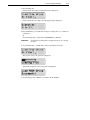
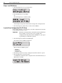
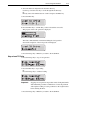
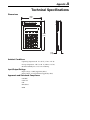
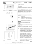
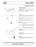
Bulletin 160 SSC™
CopyCat Keypad
FRN 2.x
User Manual
Important User Information
Solid-State equipment has operational characteristics differing from those of
electromechanical equipment. “Safety Guidelines for the Application, Installation
and Maintenance of Solid-State Controls” (Publication SGI-1.1) describes some
important differences between solid-state equipment and hard-wired
electromechanical devices. Because of this difference, and also because of the wide
variety of uses for solid-state equipment, all persons responsible for applying this
equipment must satisfy themselves that each intended application of this equipment
is acceptable.
In no event will Rockwell Automation be responsible or liable for indirect or
consequential damages resulting from the use or application of this equipment.
The examples and diagrams in this manual are included solely for illustrative
purposes. Because of the many variables and requirements associated with any
particular installation, Rockwell Automation cannot assume responsibility or
liability for actual use based on the examples and diagrams.
No patent liability is assumed by Rockwell Automation with respect to use of
information, circuits, equipment, or software described in this manual.
Reproduction of the contents of this manual, in whole or in part, without written
permission of Rockwell Automation is prohibited.
Throughout this manual we use notes to make you aware of safety considerations:
ATTENTION: Identifies information about practices or
circumstances that can lead to personal injury or death, property
damage or economic loss.
Attention statements help you to:
• identify a hazard
• avoid a hazard
• recognize the consequences
Important:
Identifies information that is especially important for successful
application and understanding of the product.
Shock Hazard labels located on or inside the drive indicate that
dangerous voltage may be present.
SSC is a trademark of Rockwell Automation, Inc.
Table of Contents
Introduction
Drive Compatibility . . . . . . . . . . . . . . . . . . . . . . . . . . . . . . . . . . . . . . . . . . . . . . . . . . . . . . . . . . . . . . . 1-1
Related Publications . . . . . . . . . . . . . . . . . . . . . . . . . . . . . . . . . . . . . . . . . . . . . . . . . . . . . . . . . . . . . . 1-1
Remote Programming Adapter . . . . . . . . . . . . . . . . . . . . . . . . . . . . . . . . . . . . . . . . . . . . . . . . . . . . . . 1-2
Removal and Installation . . . . . . . . . . . . . . . . . . . . . . . . . . . . . . . . . . . . . . . . . . . . . . . . . . . 1-2
Grounding . . . . . . . . . . . . . . . . . . . . . . . . . . . . . . . . . . . . . . . . . . . . . . . . . . . . . . . . . . . . . . 1-3
Connector Cable . . . . . . . . . . . . . . . . . . . . . . . . . . . . . . . . . . . . . . . . . . . . . . . . . . . . . . . . . . . . . . . . . 1-4
Features . . . . . . . . . . . . . . . . . . . . . . . . . . . . . . . . . . . . . . . . . . . . . . . . . . . . . . . . . . . . . . . . . . . . . . . 1-5
Display Description . . . . . . . . . . . . . . . . . . . . . . . . . . . . . . . . . . . . . . . . . . . . . . . . . . . . . . . . . . . . . . . 1-6
Drive Status Indicators . . . . . . . . . . . . . . . . . . . . . . . . . . . . . . . . . . . . . . . . . . . . . . . . . . . . . . . . . . . . 1-6
Keypad Initialization Sequence . . . . . . . . . . . . . . . . . . . . . . . . . . . . . . . . . . . . . . . . . . . . . . . . . . . . . . 1-7
How to Program the Drive
Program Group Parameters . . . . . . . . . . . . . . . . . . . . . . . . . . . . . . . . . . . . . . . . . . . . . . . . . . . . . . . . 2-1
Select a Program Group Parameter . . . . . . . . . . . . . . . . . . . . . . . . . . . . . . . . . . . . . . . . . . . . . . . . . . 2-1
Method 1 – Scroll Parameter List . . . . . . . . . . . . . . . . . . . . . . . . . . . . . . . . . . . . . . . . . . . . 2-1
Method 2 – Enter Parameter Number . . . . . . . . . . . . . . . . . . . . . . . . . . . . . . . . . . . . . . . . . 2-1
Change a Parameter Value . . . . . . . . . . . . . . . . . . . . . . . . . . . . . . . . . . . . . . . . . . . . . . . . . . . . . . . . 2-2
Method 1 – Scroll Parameter Values . . . . . . . . . . . . . . . . . . . . . . . . . . . . . . . . . . . . . . . . . 2-2
Method 2 – Enter Parameter Value . . . . . . . . . . . . . . . . . . . . . . . . . . . . . . . . . . . . . . . . . . . 2-3
Load a Drive Configuration File FROM Drive . . . . . . . . . . . . . . . . . . . . . . . . . . . . . . . . . . . . . . . . . . . 2-4
Stop a Load FROM Drive . . . . . . . . . . . . . . . . . . . . . . . . . . . . . . . . . . . . . . . . . . . . . . . . . . 2-6
Load a Drive Configuration File TO Drive . . . . . . . . . . . . . . . . . . . . . . . . . . . . . . . . . . . . . . . . . . . . . . 2-6
Stop a Load TO Drive . . . . . . . . . . . . . . . . . . . . . . . . . . . . . . . . . . . . . . . . . . . . . . . . . . . . . 2-7
Possible Load TO Drive Errors . . . . . . . . . . . . . . . . . . . . . . . . . . . . . . . . . . . . . . . . . . . . . . . . . . . . . . 2-8
Rename a Drive Configuration File . . . . . . . . . . . . . . . . . . . . . . . . . . . . . . . . . . . . . . . . . . . . . . . . . . . 2-9
Control the Drive
Enable Keypad Control to Start the Drive . . . . . . . . . . . . . . . . . . . . . . . . . . . . . . . . . . . . . . . . . . . . . . 3-1
Save Changes to Parameter 46 . . . . . . . . . . . . . . . . . . . . . . . . . . . . . . . . . . . . . . . . . . . . . . . . . . . . . 3-1
Stop the Drive . . . . . . . . . . . . . . . . . . . . . . . . . . . . . . . . . . . . . . . . . . . . . . . . . . . . . . . . . . . . . . . . . . . 3-2
Change Direction of Motor Rotation . . . . . . . . . . . . . . . . . . . . . . . . . . . . . . . . . . . . . . . . . . . . . . . . . . 3-2
Monitoring Drive Status
Display Group Parameters . . . . . . . . . . . . . . . . . . . . . . . . . . . . . . . . . . . . . . . . . . . . . . . . . . . . . . . . . 4-1
Select a Display Group Parameter . . . . . . . . . . . . . . . . . . . . . . . . . . . . . . . . . . . . . . . . . . . . . . . . . . . 4-1
Method 1 – Scroll Parameter List . . . . . . . . . . . . . . . . . . . . . . . . . . . . . . . . . . . . . . . . . . . . 4-1
Method 2 – Enter Parameter Number . . . . . . . . . . . . . . . . . . . . . . . . . . . . . . . . . . . . . . . . . 4-1
Troubleshooting
How to Clear a Fault . . . . . . . . . . . . . . . . . . . . . . . . . . . . . . . . . . . . . . . . . . . . . . . . . . . . . . . . . . . . . . 5-1
Resolving Problems . . . . . . . . . . . . . . . . . . . . . . . . . . . . . . . . . . . . . . . . . . . . . . . . . . . . . . . . . . . . . . 5-2
ii
Technical Specifications
Dimensions . . . . . . . . . . . . . . . . . . . . . . . . . . . . . . . . . . . . . . . . . . . . . . . . . . . . . . . . . . . . . . . . . . . . . A-1
Ambient Conditions . . . . . . . . . . . . . . . . . . . . . . . . . . . . . . . . . . . . . . . . . . . . . . . . . . . . . . . . . . . . . . . A-1
Input/Output Ratings . . . . . . . . . . . . . . . . . . . . . . . . . . . . . . . . . . . . . . . . . . . . . . . . . . . . . . . . . . . . . . A-1
Approvals and Standards Compliance . . . . . . . . . . . . . . . . . . . . . . . . . . . . . . . . . . . . . . . . . . . . . . . . A-1
Maintenance . . . . . . . . . . . . . . . . . . . . . . . . . . . . . . . . . . . . . . . . . . . . . . . . . . . . . . . . . . . . . . . . . . . . A-2
Chapter
1
Introduction
The CopyCat Keypad can be used to monitor and change drive parameter values,
upload and download configuration files, and control drive operation.
CopyCat Keypad
Figure 1.1
Drive Compatibility
The CopyCat Keypad is compatible with Bulletin 160 SSC™ Variable Speed Series
C drives using firmware version FRN 7.01 or higher.
Related Publications
Prior to using the CopyCat Keypad, please familiarize yourself with the following
publications for complete parameter and fault descriptions and detailed
information about hazards associated with AC drives.
• 160 SSC™ Variable Speed Drive (Series C) User Manual,
Publication 0160-5.15
• 160 SSC™ Variable Speed Drive Quick Reference Series C,
Publication 0160-5.16
1-2
Introduction
Remote Programming Adapter
The Remote Programming Adapter (160- RPA) allows the CopyCat Keypad to
interface with a Bulletin 160 Series C drive.
If your drive is equipped with a Ready/Fault Indicating Panel (160-B1) or a
Program Keypad Module (160-P1), you must remove these modules and install a
Remote Programming Adapter in order to use the CopyCat Keypad.
Removal and Installation
ATTENTION: Ensure that you disconnect line power and wait three
minutes before installing or removing the Ready/Fault Indicating
Panel or Program Keypad Module. Failure to do so could result in
personal injury or death.
ATTENTION: This drive contains ESD (Electrostatic Discharge)
sensitive parts and assemblies. Static control precautions are required
when installing, testing, servicing or repairing this assembly.
Component damage may result if ESD control procedures are not
followed. If you are not familiar with static control procedures,
reference Publication 8000-4.5.2, “Guarding Against Electrostatic
Damage” or any other applicable ESD protection handbook.
Insert a small screw driver into the slot at top of panel/keypad. Carefully pry back
and pivot the module out. Avoid bending or twisting the contact pins located
underneath the center portion of the module.
Insert the RPA module, bottom first, into the drive. Press down on the top corners
of the module until it is firmly seated.
Module Removal and Adapter Installation
U/T1 V/T2 W/T3 DC- DC+
U/T1 V/T2 W/T3 DC- DC+
Figure 1.2
Introduction
1-3
Grounding
It is required that the Remote Programming Adapter be earth grounded to improve
noise immunity and to guard the CopyCat Keypad against hazardous DC bus
potential voltages.
ATTENTION: A hazard of electrical shock exists if the Remote
Programming Adapter is not tied to earth ground. Failure to provide
an earth ground connection can result in severe personal injury or
death.
Remote Programming Adapter Ground Connection
Figure 1.3
In installations where multiple drives are used, the Remote Programming Adapters
may be linked together in order to simplify grounding of drives.
Multiple Drive Ground Connections
Ground Wire Specifications
Figure 1.4
Table 1.A
Max./Min. Wire Size
mm2 (AWG)
Max./Min. Torque
Nm (in-lb)
1.31 – 0.30 (16 – 22)
0.25 – 0.22 (2.5 – 2.2)
1-4
Introduction
Connector Cable
A cable is used to connect the CopyCat Keypad to the Bulletin 160 Series C drive.
The Keypad can be connected and disconnected when the drive is under power.
This allows you to use a single keypad with multiple drives.
Important:
If P46 - [Input Mode] is set to 2 or 6, disconnecting the CopyCat
Keypad will cause the drive to fault.
ATTENTION: Attaching earth ground to the drive control common
terminal is recommended to improve noise immunity. In addition, the
control common terminal must be grounded if the CopyCat Keypad
is to be connected or disconnected with the drive under power. Failure
to observe this precaution could result in severe bodily injury or loss
of life.
The following connector cables are available and purchased separately.
• 160-C10 – 1 meter cable, non-locking
• 160-C10R – 1 meter cable, non-locking with right angle for minimal depth
• 160-C30 – 3 meter cable, locking each end
• 160-C50 – 5 meter cable, locking each end
The 3- and 5-meter connector cables have a locking mechanism to ensure that the
cable will not be disconnected accidentally. The 1-meter connector cables do not
have a locking mechanism. To remove the cable from the drive or the CopyCat
Keypad, pull back on the plastic housing of the cable connector.
Keypad to Drive Cable Connection
Figure 1.5
Introduction
1-5
Features
The figure and table below identify and describe the CopyCat Keypad display,
status indicators, and keys.
CopyCat Keypad Features
Figure 1.6
1
4
2
3
7
5
8
6
9
10
ATTENTION: The keypad
control circuitry includes solidstate components. If hazards due
to accidental contact with
moving machinery or
unintentional flow of liquid, gas
or solids exist, an additional
hardwired stop circuit is required
to remove AC input power to the
drive. When AC input power is
removed, there will be a loss of
inherent regenerative braking
effect and the motor will coast to
a stop. An auxiliary braking
method may be required.
Feature
Description
1
Display
2 row by 16 column liquid crystal display (LCD)
2
Indicator LEDs
Four LEDs indicate mode of operation.
3
Escape Key
• Press to select mode of operation.
• Use to navigate a menu structure.
• In Edit mode, press to cancel an edit sequence.
4
Select Key
In Program mode, press to use Up or Down arrow keys to edit a parameter
value.
5
Up and Down
Arrow Keys
• In Program mode, use to scroll parameter numbers or change a parameter
value.
• In Load mode, use to select a menu option.
• In Display mode, use to scroll through display parameters.
6
Numeric Keys
0 through 9, decimal point, and Delete keys enable direct entry of parameter
values.
7
Enter Key
Press to save a new parameter value.
8
Reverse Key
Changes direction of motor rotation when keypad control is selected
(P46 = 2 or 6) and reverse is enabled (P73 = 0).
9
Start Key
Issues a start command to drive when keypad control is selected
(P46 = 2 or 6).
10 Stop Key
Issues a stop command to drive or resets a fault.
1-6
Introduction
Display Description
The keypad has a 2-row by 16-column liquid crystal display (LCD) which shows
parameter names and numbers, parameter values, fault codes, and other messages.
If the drive faults, the display will indicate the presence of the fault, and the fault
code and name will be displayed. Pressing the Up or Down arrow, Enter, or Escape
key will return the keypad to Display mode. If the fault condition is reset without
pressing one of these keys, the display will return to the display or program
parameter that was selected prior to the occurrence of the fault.
Drive Status Indicators
The keypad has four status LEDs which serve as mode and direction indicators.
LED Functions
Table 1.B
Name
Status
Description
PROGRAM
On
The keypad is in Program mode. ➊
Flashing
The keypad is in Edit mode.
LOAD
On
The keypad is in Load mode. ➊
RUN
On
The drive is running.
REVERSE
On
If keypad control is selected (P46 = 2 or 6), this LED will turn on
if the direction commanded by the keypad is reverse.
If keypad control is not selected, this LED will turn on when the
drive is running reverse.
Flashing
The direction LED will flash when the drive is commanded to
change direction. When the motor is turning in the new direction
the LED will stop flashing.
➊ When the PROGRAM and LOAD LEDs are both off, the keypad is in Display mode.
Introduction
1-7
Keypad Initialization Sequence
When the CopyCat Keypad is connected to the drive, and power is applied, the
product name and revision for the CopyCat software is displayed for two seconds.
During this time, all four indicator LEDs will be turned on to show that the LEDs
are functional.
After two seconds have elapsed, the keypad will attempt to establish serial
communication with the drive. The following is displayed:
Once communication is established, the keypad will enter Display mode. If the
communication link between the keypad and the drive is subsequently broken, the
keypad will display the above message until communication is re-established.
1-8
Introduction
End of Chapter
Chapter
2
How to Program the Drive
The CopyCat Keypad Program mode and Load mode are used to adjust and save
Program Group parameter values.
Program Group Parameters
In Program mode, the display shows the name, number, and the value of the
currently selected Program Group parameter. For example:
Not all Program Group parameters apply to both the Analog Signal Follower and
Preset Speed model drives. Refer to 160 SSC™ Variable Speed Drive (Series C)
User Manual for more information on Program Group parameters.
Select a Program Group Parameter
There are two methods for selecting a Program Group parameter. You can either
scroll through the parameter list, or enter the parameter number with the numeric
keypad.
Method 1 – Scroll Parameter List
1. Press the Escape key until the Program LED lights.
2. Press the Up or Down arrow key to scroll to the next or previous parameter.
Press and hold the Up or Down arrow key to increase scrolling speed.
The name, number, and value of the newly selected parameter is displayed.
Method 2 – Enter Parameter Number
1. Press the Escape key until the Program LED lights.
2. Enter the two-digit parameter number that you want to display using the
numeric keys.
The display shows the parameter number you entered. For example >58:
To correct an entry, press the Delete key.
Important:
To select and view Program Group parameters, the CopyCat
Keypad must be in Program mode.
2-2
How to Program the Drive
3. Press the Enter key and the newly selected parameter name, number, and value
is displayed.
If the parameter number you entered does not exist, an error message is displayed.
The cursor will blink to indicate that additional input is expected.
Press the Escape key or Enter key to return to the previous Program Group
parameter.
Change a Parameter Value
There are two methods for changing the value of a Program Group parameter.
Important:
The values of some parameters can be changed only when the drive
is stopped. If you start the drive while changing the value of one
of these parameters, the new value will not be accepted and an the
following error message is displayed.
Method 1 – Scroll Parameter Values
1. Display the Program Group parameter that you want to edit.
2. Press the Select key.
The cursor will blink at the first digit of the parameter value to indicate that the
value can be changed.
3. Press the Up or Down arrow key to increase or decrease the parameter to the
desired value.
Press and hold the Up or Down arrow key to scroll through the parameter
values. If the high or low limit for the parameter value is reached, release the
Up or Down arrow key and press and hold again to continue scrolling from the
opposite limit.
How to Program the Drive
2-3
4. Press the Enter key to save the new value to the drive.
Or
Press the Escape key to cancel the change.
Method 2 – Enter Parameter Value
1. Select a Program Group parameter to edit.
2. Press the Select key.
The cursor will blink at the first digit of the parameter value to indicate that the
value can be changed.
3. Enter the new parameter value using the decimal point and numeric keys.
Use the Delete key to erase incorrectly entered digits.
4. Press the Enter key to save the new value to the drive.
Or
Press the Escape key to cancel the change.
If a value is incorrectly formatted or is out of range, one of the following messages
is displayed:
Press the Escape key or Enter key to return to the selected parameter.
Perform Steps 2 – 4 to enter a new parameter value.
2-4
How to Program the Drive
Load a Drive Configuration File FROM Drive
Up to 15 drive configuration files can be saved to the CopyCat Keypad file directory.
The CopyCat Keypad must be in Load mode in order to load to drive, load from
drive, or name drive configuration files.
The Load Menu FROM Drive option copies the parameter values stored in the drive
to a drive configuration file stored in the CopyCat Keypad.
1. Press the Escape key until the Load LED lights.
In Load mode, the Load Menu is displayed.
There are three Load Menu options:
• TO Drive
• FROM Drive
• DEFINE Names
2. Press the Up or Down arrow key to display the Load Menu FROM Drive
option.
3. Press the Enter key to select the option.
“Load FROM Drive” and the last drive configuration file viewed in the
directory is displayed. For example:
The last two characters of the configuration file name identify the drive model.
“SF” = Analog Signal Follower and “PS” = Preset Speed.
4. Select the drive configuration file to which you want to save the drive settings.
Use the Up or Down arrow key to scroll through the file directory.
Or
Directly enter a file number between 1 and 15 and press the Enter key.
How to Program the Drive
2-5
5. Press the Enter key.
If the selected file is empty, following message is displayed.
If the selected file is not empty, the following prompt is displayed:
6. Press the Enter key to load the drive settings to an empty file or to overwrite an
existing file.
Or
Press the Escape key to cancel the Load FROM Drive command.
Important:
Overwriting an existing drive configuration file does not change
its name.
7. Press the Enter key to confirm that you have selected the correct file.
The progress of the load operation is displayed.
Successful completion of the load operation is displayed.
8. Press the Escape key or Enter key to return to the Load Menu.
2-6
How to Program the Drive
Stop a Load FROM Drive
1. Press the Escape key to stop a load operation.
2. Press the Enter key to stop loading.
Or
Press the Escape key to continue loading.
An incomplete load operation will result in an empty drive configuration file.
3. Press the Escape key or Enter key to return to the Load Menu.
Load a Drive Configuration File TO Drive
The Load Menu TO Drive option is used to load a drive configuration file from the
CopyCat Keypad module to a drive.
Important:
If the drive contains parameter values that have been modified from
factory defaults, you may want to create a backup drive
configuration file using the Load Menu FROM Drive option prior
to performing a Load To Drive operation.
1. Press the Escape key until the Load LED lights.
In Load mode, the Load Menu is displayed.
There are three Load Menu options:
• TO Drive
• FROM Drive
• DEFINE Names
2. Press the Up or Down arrow key to display the Load Menu TO Drive option.
3. Press the Enter key to select the option.
“Load TO Drive” and the last drive configuration file viewed in the directory is
displayed. For example:
How to Program the Drive
2-7
4. Select the desired configuration file from the directory.
Use the Up or Down arrow key to scroll through the file directory.
Or
Directly enter a file number between 1 and 15 and press the Enter key.
5. Press the Enter key.
6. Press the Enter key to confirm that you have selected the correct file.
The progress of the load operation is displayed.
The Start command function is disabled during the load operation.
Successful completion of the load operation is displayed.
7. Press the Escape key or Enter key to return to the Load Menu.
Stop a Load TO Drive
1. Press the Escape key to stop a load operation.
2. Press the Enter key to stop loading.
Or
Press the Escape key to continue loading.
Important:
Stopping a Load operation can produce a Drive Configuration File
with undesirable parameter combinations. Correct the problems
and complete Loading or restore parameters to the original values
before Starting the drive.
3. Press the Escape key or Enter key to return to the Load Menu.
2-8
How to Program the Drive
Possible Load TO Drive Errors
When the Enter key is pressed to begin a Load to Drive operation, an error message
is displayed if any of the following conditions exist.
The selected drive configuration file is empty or does not exist.
Press the Escape key or Enter key to return to the Load Menu.
Follow the steps beginning on page 3-6 to choose a different drive configuration file.
The drive configuration file and drive parameter sets do not match. Analog Signal
Follower and Preset Speed models are not compatible.
Press the Escape key or Enter key to return to the Load Menu.
Follow the steps beginning on page 3-6 to choose a different drive configuration file.
The drive is running or is locked.
Stop the drive or set P57 - [Program Lock] to 0 to unlock the drive.
A parameter value is either incompatible, out of range, or not recognized.
Do one of the following:
• Press the Enter key to accept the parameter value as shown and continue
loading.
• Enter a new parameter value and press Enter to continue loading.
• Press the Escape key, then
Press the Enter key to stop loading.
How to Program the Drive
Important:
2-9
Stopping a Load operation can produce a Drive Configuration File
with undesirable parameter combinations. Correct the problems
and complete Loading or restore parameters to the original values
before Starting the drive.
Rename a Drive Configuration File
By default, files that are loaded to the CopyCat Keypad are assigned a name that
contains the drive voltage, horsepower, firmware revision number, and model.
The following example shows a file that was loaded from a 230 volt,
0.75 horsepower Analog Signal Follower model drive using revision 7.04 firmware.
To rename a drive configuration file:
1. Press the Escape key until the Load LED lights.
In Load mode, the Load Menu is displayed.
There are three Load Menu options:
• TO Drive
• FROM Drive
• DEFINE Names
2. Press the Up or Down arrow key to display the Load Menu DEFINE Names
option.
3. Press the Enter key to select the option.
“DEFINE Names” and the first drive configuration file in the directory is
displayed. For example:
4. Press the Up or Down arrow key to scroll to the drive configuration file that
you want to rename.
5. Press the Enter key to place the cursor at the first character of the file name.
2-10
How to Program the Drive
6. Press the Up or Down arrow key to change the character.
Press and hold the Up or Down arrow key to scroll through the ASCII
character set. If the end or beginning of the character set is reached, release the
Up or Down arrow key and press and hold again to continue scrolling from the
opposite end.
7. Press the Enter key to save the new character.
The cursor moves one position to the right.
8. Repeat Steps 5 and 6 to change the remaining characters.
9. When finished, press the Escape key or Enter key to return to the Load Menu.
Chapter
3
Control the Drive
Enable Keypad Control to Start the Drive
The CopyCat Keypad can be used to program and control drive operation. The Stop
key is always active, but you must enable Start and direction of rotation keys.
1. Press the Escape key until the Program LED lights.
2. Use the Up or Down arrow key to scroll to P46 - [Input Mode].
Or
Enter 46 using the numeric keys and press the Enter key.
3. Press the Select key to edit the parameter value.
4. Change P46 - [Input Mode] to 2 or 6.
For detailed information regarding parameter settings, please refer to the 160
SSC™ Variable Speed Drive (Series C) User Manual, Publication 0160-5.15
5. Press the Enter key to save the new value.
Save Changes to Parameter 46
In order for changes to P46 - [Input Mode] to take effect, cycle power or set
P56 - [Reset Function] to 2
1. Use the Up or Down arrow key to scroll to P56 - [Reset Function].
Or
Enter 56 using the numeric keys and press the Enter key.
2. Press the Select key to edit the parameter value.
3. Change P56 - [Reset Function] to 2.
4. Press the Enter key to save the new value.
The new P46 - [Input Mode] value is saved and P56 - [Reset Function] resets to 0.
You can now use the CopyCat Keypad to start the drive.
Important:
The Stop/Reset digital input must be maintained in the ON state
for the keypad to start the drive.
3-2
Control the Drive
Stop the Drive
Use the Stop key to command the drive to stop. The Stop key functions in all
CopyCat Keypad modes whether or not the keypad is selected as the drive control
source.
ATTENTION: The keypad control circuitry includes solid-state
components. If hazards due to accidental contact with moving
machinery or unintentional flow of liquid, gas or solids exist, an
additional hardwired stop circuit is required to remove AC input power
to the drive. When AC input power is removed, there will be a loss of
inherent regenerative braking effect and the motor will coast to a stop.
An auxiliary braking method may be required.
Change Direction of Motor Rotation
Once the CopyCat Keypad is set to control drive operation (P46 - [Input Mode] is set
to 2 or 6) you can change the direction of motor rotation by pressing the Reverse key.
When the motor is running, pressing the Reverse key causes the motor to ramp
down to 0 Hz and then ramp up to its set speed in the opposite direction.
Chapter
4
Monitoring Drive Status
The CopyCat Keypad Display mode is used to monitor Display Group parameter
values. When serial communication with the drive has been established after power
up, the CopyCat Keypad automatically enters Display mode.
Display Group Parameters
In Display mode, the display shows the name, number, and the value of the currently
selected Display Group parameter. For example:
Not all Display Group parameters apply to both the Analog Signal Follower and
Preset Speed model drives. Refer to 160 SSC™ Variable Speed Drive (Series C)
User Manual for more information on Display Group parameters.
Select a Display Group Parameter
There are two methods for selecting a Display Group parameter. You can either
scroll through the parameter list, or enter the parameter number with the numeric
keypad.
Method 1 – Scroll Parameter List
1. Press the Escape key until the Program LED and Load LED are both off.
2. Press the Up or Down arrow key to scroll to the next or previous parameter.
Press and hold the Up or Down arrow key to increase scrolling speed.
The name, number, and value of the newly selected parameter is displayed.
Method 2 – Enter Parameter Number
1. Press the Escape key until the Program LED and Load LED are both off.
2. Enter the two-digit parameter number that you want to display using the
numeric keys.
The display shows the parameter number you entered. For example >06.
To correct an entry, press the Delete key.
Important:
To select and view Display Group parameters, the CopyCat
Keypad must be in Display mode.
4-2
Monitoring Drive Status
3. Press the Enter key and the newly selected display parameter and its value are
displayed.
If the parameter number you entered does not exist, an error message is displayed.
The cursor will blink to indicate that additional input is expected.
Press the Escape key or Enter key to return to the previous Display Group parameter.
Chapter
5
Troubleshooting
ATTENTION: Only personnel familiar with the drive and associated
machinery should plan or implement the installation, start-up, and
subsequent maintenance of the system. Failure to comply may result
in personal injury and/or equipment damage.
ATTENTION: Ensure that you disconnect line power and wait three
minutes before installing or removing the Ready/Fault Indicating
Panel or Program Keypad Module. Failure to do so could result in
personal injury or death.
How to Clear a Fault
When a fault occurs, the cause must be corrected before the fault can be cleared.
After corrective action has been taken, any of the following actions will clear the
fault.
• Press the CopyCat Keypad Stop button
• Set P54 - [Clear Fault] to 1.
• Disconnect power to the drive, wait three minutes, reapply power.
• Cycle the input signal at TB3-8 to the drive.
Please consult the 160 SSC™ Variable Speed Drive (Series C) User Manual,
Publication 0160-5.15, for a complete listing of fault descriptions and possible
problems and corrective actions.
5-2
Troubleshooting
Resolving Problems
Description
Cause
Action
Display is blank.
No power to drive (no Ready light).
Verify that the drive is under power.
Connection failure.
Verify that both ends of the connector cable
are secure.
•
•
•
•
Faulty connector cable.
RPA malfunction.
CopyCat Keypad malfunction.
Drive malfunction.
Replace components one at a time in this
order until problem is resolved:
• Connector cable
• RPA
• CopyCat Keypad
• Drive
A fault code is displayed.
There is an active fault.
Refer to the 160 SSC™ Variable Speed Drive
(Series C) User Manual, Publication 01605.15, for a complete listing of fault descriptions
and possible problems and corrective actions.
Display remains:
Connection failure.
Verify that both ends of the connector cable
are secure.
Series C drive has incompatible firmware
installed.
Use a Series C drive with firmware version
FRN 7.01 or higher.
Remote Programming Adaptor is installed on No Action. The CopyCat Keypad option is not
a 160 Series A or B drive.
compatible with 160 Series A and B drives.
•
•
•
•
Display shows:
Faulty connector cable.
RPA malfunction.
CopyCat Keypad malfunction.
Drive malfunction.
CopyCat Keypad is connected to an
incompatible drive.
Important:
Replace components one at a time in this
order until problem is resolved:
• Connector cable
• RPA
• CopyCat Keypad
• Drive
No Action. The CopyCat Keypad option is
compatible with 160 Series C drives using
firmware version FRN 7.01 or higher.
The connector cable, RPA, and Keypad are not repairable.
Appendix
A
Technical Specifications
Dimensions
89.69
(3.53)
129.49
(5.10)
24.23
(0.95)
Ambient Conditions
• Operating temperature: 0˚ C to 50˚ C (32˚ F to 122˚ F)
• Storage temperature: -40˚ C to 70˚ C (-40˚ F to 158˚ F)
• Relative humidity: 0 to 95%, non-condensing.
Input/Output Ratings
• Input voltage: 5 VDC (supplied by drive)
• Input current: 75 mA (maximum, supplied by drive)
Approvals and Standards Compliance
•
•
•
•
•
UL508C
CSA 22.2
CE
EN-50178
IP20
A-2
Technical Specifications
Maintenance
Use only a soft cloth dampened with water to clean the keypad.
ATTENTION: Hazard of electric shock, injury or death. Do not clean
the keypad when it is plugged into a drive. Unplug cable from drive
before cleaning.
The RPA requires no maintenance or cleaning.
Publication 0160-5.29ML – September, 1999
P/N 194309 (01)
Copyright 1999 Rockwell International Corporation. All rights reserved. Printed in USA.