1
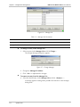
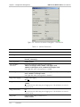
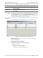
RADview-SC/TDMoIP
Network Management System
Service Center for TDMoIP Applications
ML-IP
© 1994–2005 RAD Data Communications
Publication 01/05
Contents
Chapter 1. Introduction
1.1 Overview of RADview FCAPS Model ................................................................ 1-1
1.2 System Level Operations ................................................................................... 1-1
Element Manager Window.......................................................................................1-1
1.3 Port Level Operations ....................................................................................... 1-3
Chapter 2. Fault Configuration
2.1 System Level ..................................................................................................... 2-1
Viewing Sanity Check Results ...................................................................................2-1
Chapter 3. Configuration Management
3.1 System Level ..................................................................................................... 3-1
Configuring System Information ...............................................................................3-1
Configuring Bundles.................................................................................................3-2
Displaying Time Slot Assignments.............................................................................3-3
Polling the Agent......................................................................................................3-5
Maintaining Manager List .........................................................................................3-5
3.2 Port Level.......................................................................................................... 3-7
External Port ............................................................................................................3-7
Internal Port.............................................................................................................3-9
List of Figures
1-1. Element Manager – ML-IP ......................................................................................... 1-2
1-2. Element Manager – Internal Port in Focus.................................................................. 1-3
2-1. Sanity Check Error List............................................................................................... 2-1
3-1. System Information Dialog Box.................................................................................. 3-1
3-2. Bundle Connection Table .......................................................................................... 3-2
3-3. Time Slot Assignment ................................................................................................ 3-4
3-4. Select ML Port........................................................................................................... 3-4
3-5. Channel Associated Signaling..................................................................................... 3-5
3-6. Manager List.............................................................................................................. 3-6
3-7. Change Manager ....................................................................................................... 3-6
3-8. Element Manager – External Port in Focus ................................................................. 3-7
3-9. Interface Parameters Dialog Box – External Port ....................................................... 3-8
3-10. Element Manager – Internal Port in Focus................................................................ 3-9
3-11. Interface Parameters Dialog Box – Internal Port ..................................................... 3-10
3-12. Bundle Configuration Table – Port Level................................................................ 3-11
RADview-SC/TDMoIP ML-IP User’s Manual
i
Table of Contents
List of Tables
1-1. System Management Options .................................................................................... 1-2
1-2. Internal Port Level Management Options................................................................... 1-3
1-3. External Port Level Management Options .................................................................. 1-3
2-1. Sanity Check Error Parameters................................................................................... 2-2
3-1.
3-2.
3-3.
3-4.
3-5.
3-6.
ii
System Information ................................................................................................... 3-2
Bundle Connection Parameters ................................................................................. 3-2
Manager List Parameters............................................................................................ 3-6
Interface Parameters.................................................................................................. 3-8
Interface Parameters – Internal Port......................................................................... 3-10
Bundle Configuration Table Parameters – Internal Port ............................................ 3-12
RADview-SC/TDMoIP ML-IP User’s Manual
Chapter 1
Introduction
1.1 Overview of RADview FCAPS Model
RADview provides a complete solution for monitoring and controlling ML-IP. The
RADview solutions conform to ITU-T Telecommunication Management Network
(TMN) recommendations for SNMP management systems, known as the FCAPS
model:
•
Fault management – detects and correlates fault in network devices, isolates
faults and initiates recovery actions.
•
Configuration management – tracks configuration changes, configures, installs
and distributes software and configuration files across the network.
•
Accounting management – collects accounting data and generates network
usage reports.
•
Performance management – continuously monitors network performance
(QoS, CoS) and resource allocation.
•
Security management – controls and restricts access to network resources.
1.2 System Level Operations
The element manager allows you to configure the device parameters.
To configure ML-IP via the element manager:
•
Select the node in the Service Center map and from the Configuration menu,
select Element Manager...
The Element Manager dialog box (Figure 1-1) appears allowing you to
configure any of the elements listed.
Element Manager Window
The Element Manager window allows you to configure the ML-IP at different
levels:
•
System
•
Port.
Focusing on the interface name (level) allows you to access the interface’s menus.
System Level Operations
1-1
RADview-SC/TDMoIP ML-IP User’s Manual
Chapter 1 Introduction
Figure 1-1. Element Manager – ML-IP
The ML-IP element manager allows you to monitor and configure the following
system level management options.
Table 1-1. System Management Options
Tasks – Configuration
Dialog Box and Parameter Location
Path
Viewing system information
System Information dialog box
See Configuring System Information
Configuration
System Info…
Viewing and removing
bundles
Bundle ConnectionTable
See Configuring Bundles
Configuration
Bundle Connection
Table…
Viewing timeslots
Timeslot Assignment dialog box
See Displaying Time Slot Assignments
Configuration
TS Assignment…
Polling the agent
See Polling the Agent
Configuration
Poll Agent
Tasks – Fault
Dialog Box and Parameter Location
Path
Viewing list of errors from
last sanity check
Sanity Check Errors List
See Displaying Sanity Check Results
Fault
Tasks – Options
Dialog Box and Parameter Location
Path
Establishing link between
Megaplex and manager
Manager List
See Maintaining Manager List
Options
Manager List…
1-2
System Level Operations
Sanity Check Errors…
RADview-SC/TDMoIP ML-IP User’s Manual
Chapter 1 Introduction
1.3 Port Level Operations
Focusing on the interface name (level) allows you to access the interface’s menus.
Figure 1-2. Element Manager – Internal Port in Focus
RADview for Megaplex allows you to monitor and configure the following port
level management options.
Table 1-2. Internal Port Level Management Options
Tasks – Configuration
Dialog Box and Parameter Location
Path
Setting internal port
parameters
Parameters dialog box
See Configuring Interface Parameters
Configuration
Parameters…
Configuring bundles
Bundle dialog box
See Configuring Bundles
Configuration
Bundles…
Table 1-3. External Port Level Management Options
Tasks – Configuration
Dialog Box and Parameter Location
Path
Displaying interface
parameters
Parameters dialog box
See Viewing Interface Parameters
Configuration
Interface Parameters…
Port Level Operations
1-3
Chapter 1 Introduction
1-4
Port Level Operations
RADview-SC/TDMoIP ML-IP User’s Manual
Chapter 2
Fault Configuration
This section describes Fault Configuration operation for system and port levels.
2.1 System Level
At system level you can:
•
View Sanity Check Results.
Viewing Sanity Check Results
To view the latest sanity check results:
•
From the Fault menu, select Sanity Check Errors…
The Sanity Check Error List appears displaying a list of errors and/or
warnings detected during the latest sanity check.
If the latest sanity check detected no errors, the message “NO SANITY
ERRORS” appears.
Figure 2-1. Sanity Check Error List
System Level
2-1
RADview-SC/TDMoIP ML-IP User’s Manual
Chapter 2 Fault Configuration
Table 2-1. Sanity Check Error Parameters
Parameter
Possible Values / Remarks
Slot
Slot in which the error was detected.
Card Type
Type of card in which the error was detected.
Port
Port in which the error was detected.
VAR/TS
Timeslot in which the error was detected.
Description
Brief description of the error.
[Save…]
Click Save… to save the Sanity Check Errors List in a file. The Save dialog box appears
with the default output file name output.txt. This file name can be changed, if desired.
Enter path and filename and click <OK>.
2-2
System Level
Chapter 3
Configuration Management
This section describes the different configuration operations for system and port
levels.
3.1 System Level
At system level you can:
•
Configure system information
•
Configure bundles
•
View timeslot assignments
•
Poll the agent
•
Configure managers.
Configuring System Information
To set system information for the selected Megaplex device:
1. Configuration > System Info...
The System Information dialog box appears (Figure 3-1).
2. Enter the required settings. You can change the Name, Contact and Location
fields.
3. Click <Set> to implement the changes.
Figure 3-1. System Information Dialog Box
System Level
3-1
RADview-SC/TDMoIP ML-IP User’s Manual
Chapter 3 Configuration Management
Table 3-1. System Information
Parameter
Possible Values / Remarks
Description
HW and SW information for the device
Object ID
Object ID
Name
User specified name
Contact
User specified name of contact person
Location
User specified location of Megaplex
System Up Time
Period of time system has been on
Number of Interfaces
Number of interfaces in Megaplex
Configuring Bundles
To view the bundle connection table:
•
Configuration > Bundle Connection Table…
The Bundle Connection Table appears.
Note
The Bundle Connection Table is used by all the different Megaplex products. Not all
parameters are relevant to ML-IP.
Figure 3-2. Bundle Connection Table
Table 3-2. Bundle Connection Parameters
Parameter
Possible Values/Remarks
Slot No
Slot to be configured
1–1..12
Channel No
Bundle No.
1–120
Bundle Name
Bundle name for selected channel. Table displays one bundle name per line
Admin Status
Connected, Disconnected (frames will not be sent from this channel)
Oper Status
Up, Remote Fail, Local Fail
3-2
System Level
RADview-SC/TDMoIP ML-IP User’s Manual
Chapter 3 Configuration Management
Table 3-2. Bundle Connection Parameters (Cont.)
Parameter
Possible Values/Remarks
Dest. Name
Logical name or IP address of the destination mux
Next Hop
Indicates IP address to which the Ethernet frame will be sent when the Dest.
Name IP is not in the device subnet
Dest. Bundle
Bundle number in the destination mux
1..2016
Jitter Buffer (tens of
seconds)
E1: 0..3..3200
T1: 0..3..2400
TOS
0..255
Note: TOS configuration is enabled only for circuits consisting of two IPmux–1
units. It is not available for circuits with one IPmux–1 at one end and an IPmux–4
or IPmux–16 at the other end.
TDM Bytes in Frame
E1/T1:
48..1440 (steps of 48)
Note: List of values differs for different interfaces
E3/T3:
240..1440 (steps of 48)
VLAN Tagging
Yes (checked), No (unchecked)
VLAN ID
1..4094
VLAN Priority
0..7
Rdn Bundle
NA, Number of redundant bundle
Exit Port
External–1, External–2, Auto
To remove an entry from the Bundle Connection Table:
•
Select a row in the Bundle Connection Table and click <Remove>.
Displaying Time Slot Assignments
To view time-slot assignments
1. Configuration > TS Assignment…
The Select ML Port dialog box appears.
System Level
3-3
Chapter 3 Configuration Management
RADview-SC/TDMoIP ML-IP User’s Manual
Figure 3-3. Time Slot Assignment
2. Select the desired ML-IP port and click <TS Assignment…>
The Time Slot Assignment dialog box appears.
Figure 3-4. Select ML Port
3. Select the desired timeslot and click <CAS…>
The Channel Associated dialog box appears.
3-4
System Level
RADview-SC/TDMoIP ML-IP User’s Manual
Chapter 3 Configuration Management
Figure 3-5. Channel Associated Signaling
Polling the Agent
To poll the agent:
•
Configuration > Poll Agent
The agent is polled.
Maintaining Manager List
The Manager List command enables you to establish the actual link between the
selected Megaplex device and the manager.
Note
You can define up to ten managers for each host.
To display the manager list:
•
Options > Manager List...
The Manager List appears.
System Level
3-5
RADview-SC/TDMoIP ML-IP User’s Manual
Chapter 3 Configuration Management
Figure 3-6. Manager List
Table 3-3. Manager List Parameters
Parameter
Possible Values / Remarks
Host No.
1..10
Manager IP Address IP address of the Network Management System
To change an entry in the manager list :
1. Select an entry in the Manager List and click Change…
The Change Manager dialog box appears.
Figure 3-7. Change Manager
2. Change the Manager IP Address.
3. Click <Set> to implement the changes.
To remove an entry from the Manager List:
•
Select the desired entry in the Manager List and click <Remove…>
A message appears warning about possible disconnection of the manager
during work.
3-6
System Level
RADview-SC/TDMoIP ML-IP User’s Manual
Chapter 3 Configuration Management
3.2 Port Level
The ML-IP element manager allows you to monitor and configure either External
or Internal port level management options. The functionality for both types of ports
is different and is explained below.
External Port
Focusing on the interface name (level) allows you to access the interface’s menus.
Figure 3-8. Element Manager – External Port in Focus
Viewing Interface Parameters
To view interface parameters for the external port:
1. Click the external port.
2. Configuration > Interface Parameters...
The Interface Parameters dialog box appears.
Port Level
3-7
RADview-SC/TDMoIP ML-IP User’s Manual
Chapter 3 Configuration Management
Figure 3-9. Interface Parameters Dialog Box – External Port
Table 3-4. Interface Parameters
Parameter
Possible Values / Remarks
Slot
IO slot of ML-IP card
Card Type
ML-IP
Port
Selected port
External_1..External_3
Auto Negotiation
Enable, Disable
Max Capability
Advertised
Defines the maximum capabilities of the interface
10BASE-T half duplex mode, 10BASE-T full duplex mode,
100BASE TX half duplex mode, 100BASE-TX full duplex mode
Only applicable when autonegotiation is enabled
Default Type
10BASE-T half duplex mode, 10BASE-T full duplex mode, 10BASE TX half duplex
mode, 10BASE-TX full duplex mode
Only applicable when autonegotiation is disabled
Mng VLAN Tagging
Enable VLAN tagging
Yes, No
Mng VLAN ID
VLAN ID
1..4094
This field exist only when Mng VLAN Tagging is Yes. This field does not exist for
external–3 port.
Mng VLAN Priority
0..7
This field exist only when Mng VLAN Tagging is Yes. This field does not exist for
external–3 port.
Ring Mode
Indicates If Ring Mode is enabled or not
Enable, Disable
3-8
Port Level
RADview-SC/TDMoIP ML-IP User’s Manual
Chapter 3 Configuration Management
Table 3-4. Interface Parameters (Cont.)
Parameter
Possible Values / Remarks
Protected IP Enable
Indicates whether a list of protected IP addresses is enabled or not
NA, Disable, Enable
Traffic Priority
Indicates the traffic priority of this port
NA, Low, High
Note
When Auto Negotiation is disabled and Max Capability Advertised is different
from the capabilities of the LAN (i.e. Max Capability = 100Bas-T full duplex, while
LAN works in 10BaseT half duplex), NMS will disconnect.
Internal Port
Focusing on the interface name (level) allows you to access the interface menus.
Figure 3-10. Element Manager – Internal Port in Focus
RADview for Megaplex allows you to monitor and configure the following port
level management options.
Configuring Interface Parameters
To display interface parameters for the internal port:
1. Click an internal port.
2. Configuration > Interface Parameters...
The Interface Parameters dialog box appears.
Port Level
3-9
Chapter 3 Configuration Management
RADview-SC/TDMoIP ML-IP User’s Manual
Figure 3-11. Interface Parameters Dialog Box – Internal Port
Table 3-5. Interface Parameters – Internal Port
Parameter
Possible Values / Remarks
Slot
IO slot of ML-IP card
Card Type
ML-IP
Port
Selected port
Internal_1, Internal_2
Connect
No, Yes
CAS Enable
Enables CAS
Enable (checked), Disable (unchecked)
Routing Protocol
None, RIP2, Proprietary RIP
OOS Signal
State of the signaling bits when the link is in out-of-service (OOS) state:
Forced Idle – Signaling bits A and B are idle when the link is in out-of-service
state. In addition, if the line type is ESF, signaling bits C and D are also idle.
Forced Busy - Signaling bits A and B are busy when the link is in out-of-service
state. In addition, if the line type is ESF, signaling bits C and D are also busy.
Busy Idle - Signaling bits A and B are busy for 2.5 seconds, then become idle
until the out-of-service state ends. In addition, if the line type is ESF, signaling bits
C and D are idle for 2.5 seconds before switching to busy state.
Idle Busy - Signaling bits A and B are idle for 2.5 seconds, then become busy
until the out-of-service state ends. In addition, if the line type is ESF, signaling bits
C and D are busy for 2.5 seconds before switching to idle state.
Signaling Profile
1, 2, 3, 4, 5
IP Address
IP Address
IP Mask
IP Mask
Echo Canceler
Off, On
3-10
Port Level
RADview-SC/TDMoIP ML-IP User’s Manual
Chapter 3 Configuration Management
Configuring Bundles
To configure bundles for an internal port:
1. Click an internal port.
2. Configuration > Bundles...
The Bundle Table appears.
Figure 3-12. Bundle Configuration Table – Port Level
Bundles are groups of timeslots. The Bundle Table displays the details of each
bundle in the upper section of the table, and a representation of each timeslot
with the bundle assigned to it in the lower section of the table. Each bundle can be
assigned to multiple timeslots, but each timeslot can only have one bundle
assigned to it.
Port Level
3-11
Chapter 3 Configuration Management
RADview-SC/TDMoIP ML-IP User’s Manual
Table 3-6. Bundle Configuration Table Parameters – Internal Port
Parameter
Possible Values / Remarks
Slot
IO slot of ML-IP card
Card Type
ML-IP
Port
Selected port
Internal_1, Internal_2
Bundle No.
Bundle Number
Bundle Name
Name of the selected bundle
Empty Bundle
When checked, indicates the bundle has not been assigned to any TSs (time slots)
Bundle Status
--, Up, Down, Remote Fail, Local Fail, Unavailable, Validation Fail
Time Slots
The timeslots and the bundles assigned to them. Timeslots with bundles assigned to them
are marked with a dark blue box, while unassigned time slots are marked with a gray
box.
A T1 port has 24 timeslots that can be assigned to a bundle; an E1 port has 31 (without
MF) or 30 (with MF).
Timeslots already selected as part of another bundle are colored dark blue.
Available Timeslots are colored gray.
To select an available timeslot:
1. Select a bundle from the Bundle Configuration Table and click Edit…
2. Click the square beneath the TS number.
Selected timeslots appear yellow.
3. Click <Apply>.
To select all available timeslots for the selected bundle:
•
Click <Select All>.
To remove all selected timeslots from the selected bundle:
•
Note
3-12
Click <Clear All>.
You cannot edit a bundle that has already been used to define a connection in the
Bundle Connection Table (Figure 3-2). To edit such a bundle, first delete the bundle
from the Bundle Connection Table (Configuring Bundles), and then return to the
Bundle Table to select new parameters.
Port Level