1
US008650613B2
(12) Ulllted States Patent
(10) Patent N0.:
Nocera
(54)
(45) Date of Patent:
SIMPLIFIED PAIRING FOR WIRELESS
2006/0135065 A1*
DEVICES
2006/0173838
.
.
(75)
Inventor:
(73)
Assignee: Red Hat, Inc., Raleigh, NC (US)
Bastien R. D. Nocera, Gulldford (GB)
8/2006
Garg et al.
.....
11/2006 Asokan et al. .
2006/0270350
11/2006
A1*
. . . . . ..
A1*
2009/0207014 A1 *
2010/0093319 A1*
1/2009
Kim ............. ..
Tomoda
.. 455/41.2
“ 455/41‘2
... ...
. . . . ..
8/2009 Ayed ..... ..
4/2010 Sherman
U-S-C- 154( ) Y 669
2013/0207779 A1 *
ocera
ays-
455/41.2
.. 340/53913
455/414.1
i
{Gee et a1~
2012/0254085 Al* 10/2012 Maruyama etal.
'
707/5
380/270
Zoos/0274696 A1,. 110008 Bakshi et a1‘
(21) Appl. No.: 12/619,877
Filed;
6/2006 Lee et a1. ................... .. 455/41.1
A1*
Subject to any disclaimer, the term ofthis
Patent 15 exgeltded ordadlusted under 35
'
(22)
Feb. 11, 2014
2006/0251256 A1*
2009/0017755
( * ) Notice:
US 8,650,613 B2
. . . . . . . . . . . . ..
..
43545%510;
706/20
.
8/2013 Uno et al. .................. .. 340/582
OTHER PUBLICATIONS
N0“ 17, 2009
“ConnectingYour Devices”, Bluetoothcom/Generic Pairing Instruc
tions, Printed from Internet on Feb. 16, 2010, 2 pages.
(65)
Prior Publication Data
Us 2011/0119491A1
*
May 19, 2011
't db
C1 e
'
y exammer
Primary Examiner * Nathan Flynn
(51) glglllcllég/oti
(52)
(2006 01)
U 5 Cl
Assistant Examiner * Sarah Su
'
(74) Attorney, Agent, or Firm * LoWenstein Sandler LLP
USPC ...... .. 726/3; 726/2; 726/27; 726/29; 713/169;
380/270; 455/41.1; 455/41.2
(58)
Field of Classi?cation Search
USPC _____________ __ 726/2’ 3’ 27’ 29; 713/169; 380/270;
709 037; 4 5 5 /41 _1, 412
(57)
ABSTRACT
A ?rst Wireless device is paired With a second Wireless device
for communication overaWireless connection. The ?rstWire
less device receives an input that indicates a device identi?er
See application ?le for Complete Search history
of the second Wireless device, and then matches the device
References Cited
identi?er With one of the data entries in a data repository to
obtain a code of the second Wireless device Without user
(56)
interactions. The data repository contains a plurality of data
entries associating a plurality of Wireless devices With their
corresponding codes. Based on the code of the second Wire
U.S. PATENT DOCUMENTS
7,216,231
B2 *
5/2007
Gehrmann
.................. ..
713/171
-
~
~
-
7,860,456 B2 * 12/2010 Kim ““““““““““ “ 455/4l‘2
less dev1ce, the ?rst W1rele~ss dev1ce authent1cates the second
8,291,405 B2 4
W1reless dev1ce and establ1shes the W1reless connect1on.
8,442,977 B2 *
2005/0048961 A1 *
10/2012 Buckley et a1‘ “““““ “ 717/170
5/2013 McCloskey et al. .
707/728
3/2005 Ribaudo et a1. ............. .. 455/419
20 Claims, 5 Drawing Sheets
41o
/ 400
420
RECEIVE AN INPUT THAT SELECTS AN IDENTIFIER N44o
FROM THE DISPLAYED LIST
i
MATCH THE IDENTIFIER WITH DATA ENTRIES IN A
DATA REPOSITORY TO DETERMINE A PIN FOR THE N450
NEw DEvlcE
AUTHENTICATE THE NEw DEVICE USING THE PIN
INDICATE WHETHER THE NEw DEVICE HAs BEEN
SUCCESSFULLY AUTHENTICATED
No
460
47o
'\I
N43“
YES
START WIRELESS
DENY TQEgSEI'SE'TECT'ON N495
COMMUNICATION WITH THE N490
NEw DEvlcE
US. Patent
Feb. 11,2014
ME683%mm8Em2$<1950>6%wG
Sheet 2 015
US 8,650,613 B2
50$2 0
maoStmE
w8Mj<m5a%t
@238%15
2:$165%0>
US. Patent
Feb. 11, 2014
US 8,650,613 B2
Sheet 4 0f 5
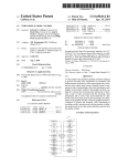
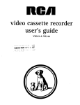
RECEIVE A REQUEST TO START A DEVICE WIZARD
@410
/
I
SEARCH DEVICES IN THE VICINITY
I
DISPLAY A LIST OF DEVICES FOUND IN THE VICINITY
N430
I
RECEIVE AN INPUT THAT SELECTS AN IDENTIFIER
FROM THE DISPLAYED LIST
N440
I
MATCH THE IDENTIFIER WITH DATA ENTRIES IN A
DATA REPOSITORY TO DETERMINE A PIN FOR THE
NEW DEVICE
I
AUTHENTICATE THE NEW DEVICE USING THE PIN
N460
I
INDICATE WHETHER THE NEW DEVICE HAS BEEN
SUCCESSFULLY AUTHENTICATED
N470
N480
YES
START WIRELESS
COMMUNICATION WITH THE
NEW DEVICE
DENY THE CONNECTION
REQUEST
FIG. 4
N490
400
US. Patent
Feb. 11,2014
Sheet 5 015
_/\_
r 502
/
US 8,650,613 B2
500
f- 510
PROCESSING DEVICE
4
DEVICE wIZARD _/ 522
LOGIC
b
4
b VIDEO DISPLAY
V530
r 504
f 512
MAIN MEMORY
ALPHA NUMERIC
DEVICE WIZARD
LOGIC
522
’
4
’
INPUT DEVICE
f 506
/— 514
CURSOR
STATIC MEMORY 4
b
4
>
CONTROL
DEVICE
(D
:3
m
r 508
r516
NETWORK
SIGNAL
INTERFACE
4———-—————>
4——-——————>
DEVICE
GENERATION
DEVICE
{518
520
SECONDARY MEMORY
MACHINE-ACCESSIBLE
STORAGE MEDIUM
4
>
DEVICE WIZARD
/— 528
DEVICE WIZARD
MODULE
<_____>
531
‘m’
LOGIC
_,/522
US 8,650,613 B2
1
2
SIMPLIFIED PAIRING FOR WIRELESS
DEVICES
FIG. 4 is a How diagram illustrating one embodiment of a
method for device pairing.
FIG. 5 illustrates a diagrammatic representation of a
machine in the exemplary form of a Wireless processing sys
TECHNICAL FIELD
tem.
Embodiments of the present invention relate to communi
cations betWeen tWo Wireless devices, and more speci?cally,
DETAILED DESCRIPTION
to the determination of a code of a Wireless device When
Described herein is a method and system for pairing Wire
establishing a connection to another Wireless device.
less devices. In one embodiment, a ?rst Wireless device is to
be paired With a second Wireless device for communication
BACKGROUND
over a Wireless connection. The ?rst Wireless device receives
an input that indicates a device identi?er of the second Wire
Many Wireless electronic devices are capable of exchang
less device, and then matches the device identi?er With one of
the data entries in a data repository to obtain a code of the
second Wireless device Without user interactions. The data
ing data over a short range distance (e.g., a feW to a hundred
meters) using Wireless data communication protocols. One of
such protocols in common use today is Bluetooth. Many of
the services offered over Bluetooth can expose private data, or
alloW a connecting device to control another device. For
example, a Bluetooth-enabled headset can be connected to a
repository contains a plurality of data entries associating a
plurality of Wireless devices With their corresponding codes.
20
mobile phone and receive the audio signals destined for the
phone. A Bluetooth-enabled mouse can be connected to a
computer and control the cursor movement on the computer.
Based on the code of the second Wireless device, the ?rst
Wireless device authenticates the second Wireless device and
establishes the Wireless connection.
In one embodiment, the Wireless devices are enabled to
communicate using the Bluetooth protocol Without the
Secure Simple Pairing (SSP) support. In contrast to the con
For security reasons, it is generally necessary to control the
device. Therefore, a conventional Bluetooth device generally
ventional pairing process, an embodiment of the invention
alloWs the Wireless devices to be paired Without the user
has a pre-determined personal identi?cation number (PIN)
manually entering or manually con?rming a PIN code (also
devices that are alloWed to gain access to a given Bluetooth
25
code that can be used for authentication purposes.
referred to as a “code”). Instead, a Wireless device can auto
The Bluetooth protocol de?nes a pairing process, Which
determines Whether tWo Bluetooth-enabled devices (also
matically look up a data repository to locate a PIN code for a
referred to “Bluetooth devices”) can be authenticated to Wire
connecting device. Data entries in the data repository may be
provided by device manufacturers and/ or softWare providers,
lessly communicate With each other. To pair tWo Bluetooth
devices that do not have the “Secure Simple Pairing” (SSP)
and can be modi?ed by a system administrator to include
information pertaining to the devices that are commonly used
30
in a speci?c environment such as an organiZation, a company
feature (Which is available in Bluetooth 2.1 or later versions),
a user typically has to manually enter PIN codes on both
devices. A device that does not have a keypad or other means
for entering the PIN code can use a pre-determined static PIN
35 or an o?ice.
In the folloWing description, numerous details are set forth.
It Will be apparent, hoWever, to one skilled in the art, that the
present invention may be practiced Without these speci?c
code for the pairing purposes. The PIN code is provided by
the manufacturers of Bluetooth devices and is usually docu
mented in the user manual. The PIN code can be used to
details. In some instances, Well-knoWn structures and devices
40
compute an encryption key, Which encrypts the Wireless link
betWeen tWo Bluetooth devices to prevent man-in-the-middle
attacks.
Conventionally, When a user Wishes to pair tWo Bluetooth
devices, the user typically has to manually enter at least one
PIN code of one of the devices during the pairing process. For
example, if one device is a headset and the other device is a
mobile phone, a user typically has to look up the PIN in the
headset’s user manual, and enter the PIN using a keypad on
the mobile phone. Once a pairing betWeen the tWo devices has
are shoWn in block diagram form, rather than in detail, in
order to avoid obscuring the present invention.
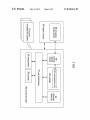
FIG. 1 illustrates an exemplary Wireless device 100 Which
implements embodiments of the invention. The Wireless
device 100 may be a computer (e.g., a server, a Workstation, a
45
personal computer (PC), a laptop, etc.), a mobile phone, a
hand-held computing device, a game station, a personal digi
tal assistant (PDA), a global positioning system (GPS)
device, etc. In one embodiment, the Wireless device 100 sup
ports a communication protocol for exchanging data Wire
50
lessly over a short range. An example of the communications
been established, the pairing is remembered by the tWo
protocol is Bluetooth, Which is an industry standard for short
devices. Subsequent connections betWeen the tWo devices
can be established Without repeating the pair process unless
the pairing relationship is removed by the user.
range Wireless communications With loW poWer consump
tion.
In one embodiment, the Wireless device 100 may also be
55
BRIEF DESCRIPTION OF THE DRAWINGS
(LAN), the Internet, or other private or public Wired netWork)
in addition to the short-range Wireless connections. The Wire
less device 100 may exchange data via the short-range Wire
The present invention is illustrated by Way of example, and
not by Way of limitation, and can be more fully understood
With reference to the folloWing detailed description When
considered in connection With the ?gures in Which:
60
FIG. 1 is a block diagram of a Wireless device Which
implements embodiments of the invention.
FIG. 2 is a diagram of one embodiment of a user interface
displayed by the Wireless device.
FIG. 3 illustrates one embodiment of data entries in a data
repository accessible by the Wireless device.
connected to a Wired netWork (e.g., a local area netWork
65
less connections With one or more connecting Wireless
devices 115, Which may be a computer, a mouse, a keyboard,
a headset, a phone, a PDA, a game station, a GPS device, etc.
In one embodiment, the Wireless device 100 includes pro
cessing unit 112, Which may include one or more processors.
The processing unit 112 executes instructions and interacts
With other functional units in the Wireless device 100. The
Wireless device 100 also includes a netWork manager 107 to
manage Wireless communications for the Wireless device
US 8,650,613 B2
3
4
100, one or more sensors 106 to detect the presence of the
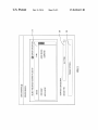
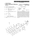
may select “headset” as a ?lter, and only the devices With
device type “headset” Will be shoWn in the WindoW 210.
Once a device is selected from the WindoW 210, the device
WiZard module 129 looks up the data repository 118 to iden
tify a PIN code for the selected device. If a PIN code cannot
be found, then the device WiZard 128 Will inform the user to
manually enter the PIN code. In one embodiment, the user can
press a “passkey options” button 260, Which causes another
WindoW to pop up. The user may manually enter the PIN code
into this other WindoW. In an alternative embodiment, the
connecting Wireless devices 115 Within the vicinity of the
Wireless device, and a transceiver 108 to transmit and receive
Wireless signals from the connecting Wireless devices 115. In
some embodiments, the sensor 106 and the transceiver 108
may be integrated into the same piece of unit, Which sWitches
betWeen a sensor mode and a transceiver mode at a high rate
(e. g., thousands of times per second). The netWork manager
107 performs a pairing process With one or more of the
connecting Wireless devices 115 to determine Which devices
115 are permitted to communicate With the Wireless device
100. The pairing process may include a sequence of hand
shakes betWeen the Wireless device 100 and a connecting
Wireless device 115 to exchange authentication information.
In one embodiment, the Wireless device 100 also includes
netWork manager 107 may be implemented to incorporate the
capability (e.g., PIN code lookups).
FIG. 3 illustrates an example of the data entries in the data
repository 118. In this example, the data entries are stored in
an XML ?le 300. The XML ?le 300 includes a collection of
data entries, each including a device identi?er and a corre
sponding code. The device identi?er may include one or more
a device Wizard module 129, Which enables a device Wizard
interface 128 to be shoWn on a display screen 127 coupled to
the Wireless device 100. The device Wizard interface 128
includes a sequence of screen displays to guide a user through
the pairing process. In an alternative embodiment, the Wire
less device 100 is not coupled to a display screen. Instead, the
Wireless device 100 has a display element integrated in its
20
example, a ?rst data entry that represents a headset of a
speci?c brand can be listed before a second data entry that
housing. For example, the display element may be a Liquid
Crystal Display (LCD) With a one-line display, Which alloWs
the user to scroll through a list of devices and select one
25
device to be paired With the Wireless device 100.
Through the device Wizard interface 128, the device Wizard
module 129 receives the device identi?er of a connecting
and may additionally include a device name and/or a device
WiZard module 129 scans the XML ?le 300 in the direction
30
Extensible Markup Language (XML) ?le) stored in a
35
memory (RAM)), non-volatile memory devices (e.g., ?ash
memory), and/ or other types of memory devices. In an alter
native embodiment, the data repository 118 may be stored in
data storage (not shoWn) coupled to the Wireless device 100.
40
generic headsets, the device Wizard module 129 Will locate
the particular PIN code instead of the generic PIN code.
In an alternative embodiment, the data repository 118 may
include multiple ?les With each ?le containing multiple data
entries. The ?les may be provided by the vendors of the
Wireless devices. Data entries in the ?les may be unsorted. In
this alternative embodiment, the device Wizard module 129
may scan all of the data entries in the ?les and determines the
best matching data entry for a selected device. The device
WiZard module 129 may ?rst identify a number of candidate
The data storage may include mass storage devices, such as
magnetic or optical storage based disks, tapes or hard drives.
According to one embodiment of the present invention, the
data repository 118 provides the PIN code for the connecting
Wireless device 115. Upon receiving an identi?er of the con
from speci?c entries to the generic entries (e.g., from top to
bottom), and stops scanning When a matching data entry is
found. Thus, if a headset of a speci?c brand uses a particular
PIN code that is different from the generic PIN code of
embodiment, the data repository 118 may be a ?le (e.g., an
memory 109 of the Wireless device 100. The memory 109
may include volatile memory devices (e.g., random access
represents generic headsets. The device identi?er of the ?rst
data entry may include an OUI to indicate the speci?c brand,
type. The device identi?er of the second data entry may
include only the device type and not the OUI. The device
Wireless device 115 that a user Wishes to connect to the
Wireless device 100. The device WiZard module 129 uses the
device identi?er to look up a matching data entry in a data
repository 118 that contains a collection of data entries. In one
of a device name, an organiZationally unique identi?er (OUI),
and a device type. In one embodiment, the data entries in the
?le may be sorted in an order from speci?c to generic. For
45
necting Wireless device 115, the device WiZard module 129
looks up a matching data entry, Which contains the PIN code
associated With the connecting Wireless device 115. There is
no user interaction for entering the PIN code. The PIN code is
used to authenticate the connecting Wireless device 115, and
establishes a connection With the connecting Wireless device
115 if the authentication is successful. After the connection is
established, the Wireless device 100 communicates With the
connecting Wireless device 115 using the transceiver 108.
50
FIG. 2 illustrates an example of a screenshot of the device
WiZard 128. The device WiZard 128 displays a list of devices
55
data entries With each candidate data entry being associated
With a Weighting factor. For example, a candidate data entry
that matches both the OUI and the device type is Weighed
more heavily than another candidate data entry that only
matches the device type. The device WiZard module 129 then
determines a matching data entry as the candidate data entry
that has the most Weight.
In the embodiment of FIG. 3, it is shoWn that some of the
PIN codes are pre-determined ?xed-length numbers 310
(e.g., “0000”). Some of the PIN codes are random numbers up
to a maximum number of digits 320 (e.g., max: 4). Some of
the PIN codes are shoWn as “NULL” 330, Which indicates
that the devices Will not be paired, but Will be connected
(i.e., the connecting Wireless devices 115) that have been
found in the vicinity (i.e., Within the Wireless communication
range) of the Wireless device 100. The list of devices may be
Without an encrypted connection and Will be marked as
trusted. The “NULL” 330 can be used for devices such as
shoWn in a scrollable WindoW 210. Each device is shoWn as a 60
mice and joypads Where there is no encryption.
Referring to FIG. 2 and FIG. 3, in one embodiment, the
device name and a corresponding device type (also referred to
device names shoWn in WindoW 210 are the same as the device
as a “device class”). A user can select from the list a device
names in the ?le 300. The device names in both places are
that he Wants the Wireless device 100 to pair With. In one
embodiment, the device WiZard 128 also includes a ?lter
function that ?lters the devices shoWn in the WindoW. For
example, When a user presses a button 250, a list of available
device types Will be shoWn in a pull-doWn menu. The user
provided by the corresponding remote devices (e.g., the con
necting Wireless devices 115). HoWever, the device names
may be someWhat cryptic (e.g. “CMT-DHSBT,” instead of
“Sony Bluetooth speakers CMT-DHSBT”). In one embodi
65
ment, for a device that Was previously knoWn and paired With
US 8,650,613 B2
5
6
the Wireless device 100, an end user may change the device
personal computer (PC), a tablet PC, a set-top box (STB), a
Personal Digital Assistant (PDA), a cellular telephone, a Web
name in the WindoW 210 to a name more descriptive and
meaningful to that user.
appliance, a server, a netWork router, sWitch or bridge, or any
For certain input devices the device WiZard module 129
may implement a helper function that detects the absence of
machine capable of executing a set of instructions (sequential
or otherWise) that specify actions to be taken by that machine.
Further, While only a single machine is illustrated, the term
a peripheral device (e.g., an input device such as a mouse or a
keyboard) on the system. When the absence of the device is
detected, the helper function automatically looks for such a
device in the vicinity and informs the user of this action.
“machine” shall also be taken to include any collection of
machines (e.g., computers) that individually or jointly
execute a set (or multiple sets) of instructions to perform any
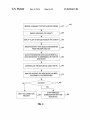
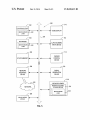
FIG. 4 is a How diagram illustrating one embodiment of a
one or more of the methodologies discussed herein.
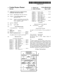
The exemplary computer system 500 includes a processing
device 502, a main memory 504 (e. g., read-only memory
(ROM), ?ash memory, dynamic random access memory
(DRAM) such as synchronous DRAM (SDRAM) or Rambus
DRAM (RDRAM), etc.), a static memory 506 (e.g., ?ash
memory, static random access memory (SRAM), etc.), and a
secondary memory 518 (e.g., a data storage device), Which
method 400 for pairing tWo Wireless devices. The method 400
may be performed by computer system 500 of FIG. 5 that may
comprise hardWare (e. g., circuitry, dedicated logic, program
mable logic, microcode, etc.), softWare (e. g., instructions run
on a processing device to perform hardWare simulation), or a
combination thereof. In one embodiment, the method 400 is
performed by the Wireless device 100 of FIG. 1.
Referring to FIG. 4, in one embodiment, the method 400
begins When the Wireless device 100 receives a request to
activate the device WiZard module 129 for adding a neW
20
communicate With each other via a bus 530.
The processing device 502 represents one or more general
purpose processing devices such as a microprocessor, central
connection to the Wireless device 100 (block 410). The
processing unit, or the like. More particularly, the processing
request may be in the form of a user launching the device
WiZard interface 128 on the display screen 127 of the Wireless
device 100. After the device WiZard interface 128 is launched,
the Wireless device 100 searches the other Wireless devices in
the vicinity (block 420). The Wireless device 100 may use one
device 502 may be a complex instruction set computing
(CISC) microprocessor, reduced instruction set computing
(RISC) microprocessor, very long instruction Word (VLIW)
25
sets, or processors implementing a combination of instruction
sets. The processing device 502 may also be one or more
or more sensors 106 to detect the presence of the other Wire
special-purpose processing devices such as an application
less devices. These other Wireless devices support the same
Wireless communication protocol as the Wireless device 100.
For short-range Wireless communications, this protocol may
be the Bluetooth protocol. The siZe of the vicinity Within
30
by the Bluetooth protocol.
After the devices in the vicinity are found, the Wireless
35
127 (block 430). The list of devices shoWn on the display
screen 127 may be ?ltered by the user to shoW only a speci?c
type of the device. The user may select one of the listed
devices as the neW device to be connected. Through the
device WiZard interface 128, the device WiZard module 129
speci?c integrated circuit (ASIC), a ?eld programmable gate
array (FPGA), a digital signal processor (DSP), netWork pro
cessor, or the like. The processing device 502 is con?gured to
Which Wireless communication can be performed is de?ned
device 100 displays a list of the devices on its display screen
microprocessor, processor implementing other instruction
execute the device Wizard logic 522 for performing the opera
tions and steps discussed herein.
The computer system 500 may further include a netWork
interface device 508. The computer system 500 also may
include a video display unit 510 (e. g., a liquid crystal display
(LCD) or a cathode ray tube (CRT)), an alphanumeric input
device 512 (e.g., a keyboard), a cursor control device 514
(e.g., a mouse), and a signal generation device 516 (e.g., a
40
speaker).
receives an identi?er (e. g., a device name and a device type)
The secondary memory 518 may include a machine-read
of the neW device (block 440). The device Wizard module 129
then matches the identi?er With the data entries in the data
repository 118 to determine the PIN code for the neW device
(block 450). After the PIN code is found, the netWork man
able storage medium (or more speci?cally a computer-read
able storage medium) 531 on Which is stored one or more sets
of instructions (e.g., device WiZard logic 522) embodying any
45
ager 107 uses the PIN code to authenticate the neW device
(block 460). The Wireless device 100 may start a sequence of
handshakes With the neW device to exchange authenticating
information. Upon completion of the handshakes, the Wire
less device 100 may display a message to indicate Whether the
50
neW device has been successfully authenticated (block 470).
If the neW device has been successfully authenticated (block
480), the Wireless device 100 can start Wireless communica
tion With the neW device (block 490). If the neW device cannot
be authenticated (block 480), the Wireless device 100 denies
the request for connecting to the neW device (block 495).
ted or received over a netWork 520 via the netWork interface
55
FIG. 5 illustrates a diagrammatic representation of a
machine in the exemplary form of a computer system 500
Within Which a set of instructions, for causing the machine to
perform any one or more of the methodologies discussed
herein, may be executed. In alternative embodiments, the
machine may be connected (e.g., netWorked) to other
machines in a Local Area NetWork (LAN), an intranet, an
extranet, or the Internet. The machine may operate in the
one or more of the methodologies or functions described
herein (e.g., the device WiZard module 129 of FIG. 1). The
device WiZard logic 522 may also reside, completely or at
least partially, Within the main memory 504 and/or Within the
processing device 502 during execution thereof by the com
puter system 500; the main memory 504 and the processing
device 502 also constituting machine-readable storage
media. The device WiZard logic 522 may further be transmit
60
device 508.
The machine-readable storage medium 531 may also be
used to store the device WiZard logic 522 persistently. While
the machine-readable storage medium 531 is shoWn in an
exemplary embodiment to be a single medium, the term
“machine-readable storage medium” should be taken to
include a single medium or multiple media (e. g., a centraliZed
or distributed database, and/ or associated caches and servers)
that store the one or more sets of instructions. The term
“machine-readable storage medium” shall also be taken to
include any medium that is capable of storing or encoding a
set of instructions for execution by the machine that cause the
capacity of a server or a client machine in a client-server 65
machine to perform any one or more of the methodologies of
netWork environment, or as a peer machine in a peer-to -peer
(or distributed) netWork environment. The machine may be a
the present invention. The term “machine-readable storage
US 8,650,613 B2
7
8
medium” shall accordingly be taken to include, but not be
tion beloW. In addition, the present invention is not described
limited to, solid-state memories, and optical and magnetic
With reference to any particular programming language. It
Will be appreciated that a variety of programming languages
media.
The computer system 500 may additionally include a
device Wizard module 528 for implementing the functional
ities of the device WiZard module 129 of FIG. 1. The module
may be used to implement the teachings of the invention as
described herein.
It is to be understood that the above description is intended
to be illustrative, and not restrictive. Many other embodi
ments Will be apparent to those of skill in the art upon reading
528, components and other features described herein (for
example in relation to FIG. 1) can be implemented as discrete
hardWare components or integrated in the functionality of
hardWare components such as ASICS, FPGAs, DSPs or simi
lar devices. In addition, the module 528 can be implemented
and understanding the above description. Although the
present invention has been described With reference to spe
ci?c exemplary embodiments, it Will be recogniZed that the
as ?rmware or functional circuitry Within hardWare devices.
invention is not limited to the embodiments described, but can
Further, the module 528 can be implemented in any combi
nation of hardWare devices and softWare components.
be practiced With modi?cation and alteration Within the spirit
and scope of the appended claims. Accordingly, the speci?
Some portions of the detailed descriptions Which folloW
are presented in terms of algorithms and symbolic represen
cation and draWings are to be regarded in an illustrative sense
rather than a restrictive sense. The scope of the invention
tations of operations on data bits Within a computer memory.
should, therefore, be determined With reference to the
These algorithmic descriptions and representations are the
appended claims, along With the full scope of equivalents to
means used by those skilled in the data processing arts to most
effectively convey the substance of their Work to others
skilled in the art. An algorithm is here, and generally, con
ceived to be a self-consistent sequence of steps leading to a
Which such claims are entitled.
20
1. A method comprising:
receiving a device identi?er of a second Wireless device
that is to be connected to a ?rst Wireless device;
desired result. The steps are those requiring physical manipu
lations of physical quantities. Usually, though not necessarily,
these quantities take the form of electrical or magnetic signals
What is claimed is:
checking a data repository comprising a plurality of data
25
entries that associate a plurality of Wireless devices With
corresponding codes;
capable of being stored, transferred, combined, compared,
and otherWise manipulated. It has proven convenient at times,
matching, by a processing device, the device identi?er With
principally for reasons of common usage, to refer to these
one of the plurality of data entries in the data repository,
Wherein each of the plurality of data entries comprise an
signals as bits, values, elements, symbols, characters, terms,
numbers, or the like.
30
It should be borne in mind, hoWever, that all of these and
similar terms are to be associated With the appropriate physi
cal quantities and are merely convenient labels applied to
these quantities. Unless speci?cally stated otherWise, as
apparent from the folloWing discussion, it is appreciated that
throughout the description, discussions utiliZing terms such
as “receiving”, “checking”, “matching”, “authenticating”, or
35
the like, refer to the action and processes of a computer
system, or similar electronic computing device, that manipu
lates and transforms data represented as physical (electronic)
quantities Within the computer system’ s registers and memo
ries into other data similarly represented as physical quanti
organiZationally unique identi?er (OUI) and a device
type, Wherein the matching comprises applying a Weigh
ing factor to each of the plurality of data entries in vieW
of the OUI and the device type, Wherein the Weighing
factor is greater for the match of the device identi?er
With combination of the OUI and the device type than for
the match of the device identi?er With the device type;
determining a code of the second Wireless device in vieW of
the match of the device identi?er With one of the plural
ity of data entries; and
40
ties Within the computer system memories or registers or
other such information storage, transmission or display
devices.
Embodiments of the present invention also relates to an
authenticating the second Wireless device in vieW of the
code.
2. The method of claim 1, Wherein a Wireless connection is
established betWeen the ?rst Wireless device and the second
Wireless device using a Bluetooth protocol Without support of
Secure Simple Pairing (SSP).
3. The method of claim 1, further comprising:
apparatus for performing the operations herein. This appara
detecting, by the processing device, other Wireless devices
tus may be specially constructed for the required purposes, or
in a vicinity of the ?rst Wireless device, the second
Wireless device being one of the other Wireless devices;
and
displaying a list of the other Wireless devices detected in
it may comprise a general purpose computer system selec
tively programmed by a computer program stored in the com
50
puter system. Such a computer program may be stored in a
computer readable storage medium, such as, but not limited
the vicinity on a display screen.
to, any type of disk including ?oppy disks, optical disks,
CD-ROMs, and magnetic-optical disks, read-only memories
(ROMs), random access memories (RAMs), EPROMs,
4. The method of claim 1, Wherein the code is represented
55
by one of a pre-determined ?xed-length number or a random
number having a maximum number of digits, or null.
EEPROMs, magnetic disk storage media, optical storage
5. The method of claim 1, Wherein the matching the device
media, ?ash memory devices, other type of machine-acces
sible storage media, or any type of media suitable for storing
electronic instructions, each coupled to a computer system
identi?er further comprises:
scanning the data repository, in a direction from speci?c
bus.
The algorithms and displays presented herein are not inher
ently related to any particular computer or other apparatus.
Various general purpose systems may be used With programs
in accordance With the teachings herein, or it may prove
convenient to construct more specialiZed apparatus to per
form the required method steps. The required structure for a
variety of these systems Will appear as set forth in the descrip
entries to generic entries, to determine a matching data
entry for the second Wireless device, Wherein each of the
speci?c entries comprises the OUI and each of the
65
generic entries comprises the device type; and
stopping scanning of the data repository When the match
ing data entry is found.
6. The method of claim 1, further comprising:
detecting absence of an input device associated With the
?rst Wireless device;
US 8,650,613 B2
10
searching for the input device in the vicinity; and
informing the user that a search is being performed for the
input device.
7. The method of claim 1, further comprising:
providing a graphical user interface (GUI) to shoW a pass
5
informing a user that a search is being performed for the
key option, the passkey option alloWing a user to enter
input device.
the code of the second Wireless device When the code is
not found in the data repository.
8. A non-transitory computer readable storage medium that
provides instructions, Which When executed by a processing
device, cause the processing device, to perform operations
14. The non-transitory computer readable storage medium
of claim 8, the operations further comprising:
10
a memory;
a processing device coupled to the memory, the processing
checking a data repository comprising a plurality of data
device to:
receive a device identi?er of a second Wireless device to be
connected to a ?rst Wireless device,
entries that associate a plurality of Wireless devices With
corresponding codes;
matching, by the processing device, the device identi?er
With combination of the OUI and the device type than for
the match of the device identi?er With the device type;
determining a code of the second Wireless device in vieW of
the match of the device identi?er With one of the plural
20
corresponding codes,
25
30
9. The non-transitory computer readable storage medium
Simple Pairing (SSP).
17. The system of claim 15, the processing device to:
detect other Wireless devices in a vicinity of the ?rst Wire
less device, and
display to shoW a list of the other Wireless devices detected
in the vicinity.
45
the vicinity on a display screen.
18. The system of claim 15 Wherein the code is represented
by one of a pre-determined ?xed-length number or a random
number having a maximum number of digits, or null.
19. The system of claim 15, the processor to:
detect absence of an input device associated With the ?rst
comprises:
of claim 8, Wherein the code is represented by one of a
pre-determined ?xed-length number or a random number
having a maximum number of digits, or null.
authenticate the second Wireless device in vieW of the code.
16. The system of claim 15, Wherein a Wireless connection
is establishedbetWeen the ?rst Wireless device and the second
Wireless device using a Bluetooth protocol Without support of
Secure Simple Pairing (SSP).
40
11. The non-transitory computer readable storage medium
of claim 8, Wherein the matching the device identi?er further
scanning the data repository, in a direction from speci?c
entries to generic entries, to determine a matching data
entry for the second Wireless device, Wherein each of the
speci?c entries comprises the OUI and each of the
generic entries comprises the device type; and
stopping scanning of the data repository When the match
ing data entry is found.
12. The non-transitory computer readable storage medium
plurality of data entries in vieW of the OUI and the device
type, Wherein the Weighing factor is greater for the
match of the device identi?er With combination of the
OUI and the device type than for the match of the device
identi?er With the device type,
ity of data entries and
35
device using a Bluetooth protocol Without support of Secure
in a vicinity of the ?rst Wireless device, the second
Wireless device being one of the other Wireless devices;
and
displaying a list of the other Wireless devices detected in
entries in the data repository, Wherein each of the plu
rality of data entries comprise an organiZationally
unique identi?er (OUI) and a device type, Wherein the
match comprises apply a Weighing factor to each of the
determine a code of the second Wireless device in vieW of
the match of the device identi?er With one of the plural
code.
10. The non-transitory computer readable storage medium
of claim 8, the operations further comprising:
detecting, by the processing device, other Wireless devices
check a data repository comprising a plurality of data
entries that associate a plurality of Wireless devices With
match the device identi?er With one of the plurality of data
ity of data entries; and
authenticating the second Wireless device in vieW of the
of claim 8, Wherein a Wireless connection is established
betWeen the ?rst Wireless device and the second Wireless
key option, the passkey option alloWing a user to enter
15. A system comprising:
receiving a device identi?er of a second Wireless device
that is to be connected to a ?rst Wireless device;
prise an organiZationally unique identi?er (OUI) and a
device type, Wherein the matching comprises applying a
Weighing factor to each of the plurality of data entries in
vieW of the OUI and the device type, Wherein the Weigh
ing factor is greater for the match of the device identi?er
providing a graphical user interface (GUI) to shoW a pass
the code of the second Wireless device When the code is
not found in the data repository.
comprising:
With one of the plurality of data entries in the data repo si
tory, Wherein each of the plurality of data entries com
13. The non-transitory computer readable storage medium
of claim 8, the operations further comprising:
detecting absence of an input device associated With the
?rst Wireless device;
searching for the input device in a vicinity; and
50
55
Wireless device;
search for the input device in a vicinity; and
inform a user that a search is being performed for the input
device.
20. The system of claim 15, the processor to:
provide a graphical user interface (GUI) to shoW a passkey
option, the passkey option alloWing a user to enter the
code of the second Wireless device When the code is not
found in the data repository.
*
*
*
*
*