1
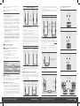
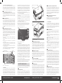
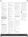
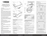
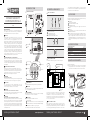
1.0 INTRODUCTION in the simple alarm system outlined above – as a closed circuit with all switches wired in a loop. Zipabox Security module implements essential features of a wired alarm panel. 2.0 WIRED ALARM BASICS CONNECTION POINTS TYPES OF CONTACTS NO ZIPABOX SECURITY EXPANSION MODULE NC NC 3.0 FEATURES NO Zipabox Security Module supports adds wired alarm functionality to Zipabox. Security module adds support for: 6 wired zones 1 optically isolated 12V input 1 supervised wired bell/siren output 1 programmable output 1 supervised 12V auxiliary power supply for powered wired sensors 1 USB port 1 serial/UART port, user selectable between RS-232 mode and half-duplex RS-485 mode 1 lead acit batter charger (when using Security Module as a basis for an alarm system, the Backup Module can not provide enough voltage to support wired sensors/siren and can not be used to power Zipabox and modules in case of a power failure. Please use SLA (Sealed Lead Acid) battery for power backup with Security module) QUICK INSTALLATION GUIDE v1.2 C SPST (NO) TRADEMARKS Zipato and the Zipato logo are registered Trademarks. All other product names mentioned herein may be trademarks or registered trademarks of their respective companies. Top view NOTICE Although Zipato has attempted to ensure the accuracy of the content of this manual, it is possible that this document may contain technical inaccuracies, typographical, or other errors. Zipato assumes no liability for any error in this publication, and for damages, whether direct, indirect, incidental, and consequential or otherwise, that may result from such error, including, but not limited to loss of data or profits. Zipato provides this publication “as is” without warranty of any kind, either express or implied, including, but not limited to implied warranties of merchantability or fitness for a particular purpose. The published information in the manual is subject to change without notice. Zipato reserves the right to make changes in the product design, layout, and driver revisions without notification to its users. This version of the Installation guide supersedes all previous versions. Where: C is the Common terminal NO is Normally Open contact NC is Normally Closed contact Different symbols for NO and NC contacts: Bottom view NO Left side view TAKE CARE OF YOUR SAFETY Display extreme caution when using ladders or steps, please follow manufacturer’s instructions. Be careful when using hand and power tools and follow the manufacturer’s guidelines when using them. Take care that the correct tools are used. Wear goggles or protective clothing where required. DANGER 4.0 SPECIFICATIONS NC Different symbols for resistors: IEC ELECTROMAGNETIC COMPATIBILITY In proper state and when operated properly, the product complies with all the requirements in respect of interference radiation according to EN 301 489-17, EN 301 489-1 and EN 300 328. The connections conducting HF signals must neither be manipulated nor damaged. C C SPST (NC) SPDT (B-M) TEMPERATURE RANGE 0 - 50ºC HUMIDITY RANGE 0-95% RH POWER powered by Zipabox AUX POWER 10-14 VDC 800mA BELL/SIREN OUT 10-14 VDC 600 mA SIREN IN 8-14VDC, 20mA max PGM OUT 150mA max solid state relay with selectable active level (see 3.5) IEEE SIMPLE WIRED ALARM The most basic wired alarm system is a closed circuit system: 1 RS-232-RX 2 RS-232-TX 01 Power off you Zipabox 02 C onnect security module to the left side (slot 1) of the Zipabox (if using Zipato Power or Backup module, Security module connects after those modules) as shown int he picture bellow. Alarm oor/Window D Sensor 3 RS-485-A 4 RS-485-B 1 2 3 4 5 5.0 INSTALLATION NOTES Copper Wires 1 5 C OM RISK OF ELECTROCUTION All work on the device should only be carried out by trained and skilled electricians. Observe the country-specific regulations. CAUTION The connected devices and the flush-mounted receiver can become damaged if devices are operated that do not correspond to the technical specifications (see technical data). DANGER RISK OF FATAL INJURY FROM ELECTRIC CURRENT. The device has no basic insulation and must therefore be installed in a way that protects against accidental contact. DANGER RISK OF FATAL INJURY FROM ELECTRIC CURRENT. When installing a wall plate, the distance between the cover’s fixing brackets or screws and the connections of the flush - mounted MM Switch Single must be at least 4 mm once installed. If the distance is less than 4 mm, a deeper installation box must be used. The fixing brackets or screws of the cover must not press against the housing. Only insulated tools may be used for operation on the device, e.g. an insulated phase tester. make your home smart COMPATIBILITY Door to outside Window door This Expansion Module is designed to work only with Zipabox. HANDLING Do not drop, knock or shake the module. Rough handling can break internal circuit boards and connectors. ENVIRONMENT Do not expose the module to excessive heat or cold, as it can damage or shorten the life of electronic circuit boards. UNPACKING Zipabox Security Expansion Module consists of: 1x Security Module 12x resistors of 5.6kΩ value (see section 3.1 Zone Wiring [Z1-Z6]) 2x resistors of 1kΩ value (see section 3.3 Supervised Bell/Siren Output). If possible, dispose this module at a recycling center. Do not dispose of this module with the household waste. www.zipato.com Glass Break Sensor In this basic security system, all switches have normally closed (NC) contacts. All switches are in a wiring loop. When the doors and windows are shut, switches attached to them are closed. Opening any one of the switches breaks the loop and triggers the alarm circuit. The alarm will also activate if the loop is broken – if wire is cut, alarm will activate. 2 WIRED ALARM SYSTEM Modern alarm panels are advanced versions of the basic system outlined above – they usually support multiple wired zones, lead acid battery backup (for power blackouts), external siren and advanced user interface (graphical display). Each wired zone can be used as make your home smart www.zipato.com 01 1 Align connector of to expansion Slot 1 of Zipabox (or to module connected into Slot 1) 2 Join module and Zipabox together until gap between them is completely closed. 03 C onnect your wired sensors to Zone1-6. 04 C onnect output from your existing panel or some external sensor to terminals marked IN+/IN-. 05 C onnect your wired bell/siren to terminals marked BELL+/BELL. 06 If using any powered sensors, connect them to AUX+/AUX- terminals. 07 C onnect a relay or other low power 12V device to the PGM output. 08 C onnect a lead acid, 12 V battery to terminals marked BAT+/BAT. Warning: Failing to observe correct polarity while connecting battery will result in a shorted fuse! 09 If applicable, connect a supported USB device to the USB port. 10 If applicable, connect a supported device to the serial port. 11 R estore power to your Zipabox. When the top button on the Zipabox turns solid green, your module is ready for configuration and use. 12 L ogin to my.zipato.com and click on “General”, “Device Manager” and locate Security module. 13 U nhide all zones you wish to use (zones are hidden by default). On the configuration page for each zone, select wiring type. PLEASE MAKE SURE THE WIRING TYPE SELECTED ON THE CONFIGURATION PAGE CORRESPONDS TO ACTUAL ZONE WIRING! OTHERWISE WRONG EVENTS WILL BE REPORTED! 14 A fter saving changes, press “Synchronize” button to transfer them to your Zipabox. 15 C onfigure your alarm widget and automation rules with the newly added functionality! INSTALLATION/MOUNTING NORMALLY CLOSED LOOP Zone terminal COMMON 1 | Connect 3G stick to USB port of the Security module 2 | Go to Zipato “Control Center” 3 | Click on “General” settings on the left sidebar 4 | Click on “Zipabox settings” 5 | Fill in 3G Backup fields (see picture below) 6 | Save everything 7 | Synchronize changes by pressing the“Synchronize” button on the left sidebar COMMON Zone terminal In normally closed zone configuration (wired loop with normally closed contacts): 01 S ecurity module views short circuit as normal condition and an open circuit as a fault or alarm condition. 02 If the wired loop is shorted (by accident or malice), that state is indistinguishable from normal condition. The purpose of end-of-line resistors (EOLR’s) is to allow Security module to differentiate between an active alarm, tampering with sensor wiring, and a short in a wire. EOLR’s have to be installed at the last device on the loop, and not at the Security module terminals. Placing resistors anywhere other than at the sensor contact does NOTHING to supervise the wiring, which is the purpose for using resistors. With NC contact, EOLR’s are optional. When put in, they detect whether the wiring was shorted. NORMALLY OPEN Normal Tampered COMMON Zone terminal COMMON For this zone configuration to be active, in the Zipabox interface go to Device Manager, select Security module and appropriate zone, and select ‘Normally closed zone’ from the ‘Zone Wiring’ drop-down. Normally closed zone is the most basic wiring type. In this configuration, connect one or more normally closed (NC) contacts in a wiring loop. Each contact may be a sensor or a tamper contact. User interface for this zone will display INACTIVE status when the loop is closed, and ACTIVE status when the loop is open. Upon zone state change, both sensor and tamper events will be generated (tamper events are visible in the Alarm panel). make your home smart Zone COMMON Zone terminal COMMON Single NO door/window sensor with single EOLR: Sensor Zones COMMON For this zone configuration to be active, in the Zipabox interface go to Device Manager, select Security module and appropriate zone, and select ‘Double end-of-line resistor zone’ from the Zone Wiring drop-down. This zone configuration is used with NC contacts and allows Security module to further differentiate between open (activated) contact and tampered (cut) loop. At the sensor side, one resistor is placed in series with NC sensor contact, while one resistor is placed in parallel with the contact. Single NO door/window sensor with double EOLR: Sensor Zones COMMON Zone COMMON Normally closed contact with double end of line resistor In this configuration, more NC tamper contacts can be wired in series with the first one: For this zone configuration to be active, in the Zipabox interface go to ‘Device Manager’, select Security module and appropriate zone, and select ‘Single end-of-line resistor zone’ from the ‘Zone Wiring’ drop-down. A single resistor is placed in series with NC contact, or in parallel with a NO contact. Normally closed contact with end of line resistor Normally open contact with end of line resistor Zone terminal Zone terminal COMMON COMMON DOUBLE END-OF-LINE RESISTOR Zone terminal COMMON Multiple NO sensors in parallel with single EOLR: Sensor Zones Zone Alarm contact 5.1.1 NORMALLY CLOSED ZONE Sensor Zones 5.1.4 DOUBLE END-OF-LINE (DEOL) RESISTORS 5.1.3 SINGLE END-OF-LINE (SEOL) RESISTOR Zones can be wired as normally closed loops, with single (SEOL) or double end-of-line (DEOL) resistors. Please use wiring appropriate for your sensor contact/s. Make sure not to exceed 400m maximum wire length per zone. Resistor value is 5.6kΩ. Single NC door/window sensor: Zone Zone terminal NO contacts should always use EOLR’s. Without resistors, there is no way to differentiate between a fault (broken wire) and a normal condition. 5.1 ZONE WIRING (Z1-Z6) COMMON One or more normally closed contacts and one or more normally opened contacts with end-of-line resistor 5.1.2 END OF LINE RESISTORS Zone terminal 5.1.5 EXAMPLES OF SENSOR WIRING SINGLE END-OF-LINE RESISTOR One or more normally closed contacts with no end-ofline resistor Meant for mounting only with Zipabox. INSTALLING AND CONFIGURING 3G BACKUP (OPTIONAL) Zone terminal In this zone configuration, Security module treats NC contact as a tamper contact, and NO contact as a sensor contact, and sends events correspondingly. As in the closed loop configuration, multiple contacts can we wired to a single zone, while observing the rule – NC contacts in series, NO in parallel: COMMON Tamper contact Tamper contact One normally closed ALARM contact and one or more normally closed tamper contacts with double end-of-line resistor www.zipato.com make your home smart www.zipato.com 02 5.2 OPTICALLY ISOLATED INPUT (IN+/IN-) Connect a device that provides voltage output of 8-14 VDC, with positive wire going to terminal marked IN+ and negative wire going to IN-. This input will consume no more than 40mA of current, and has an internal 1kΩtermination resistor (so this input can be used to interface Security module with existing alarm panel siren output). 5.3 SUPERVISED BELL/SIREN OUTPUT Bell output will supply 600mA of current at 12VDC. The output is supervised and power limited. If unused, connect a 1kΩtermination resistor to across BELL+ and BELL- terminals to prevent tamper event generation. Bell output is protected from over-current by an electronic fuse. 5.4 AUX POWER OUTPUT For powering wired sensors that require 12VDC, connect respective wires to the AUX+ and AUX- power terminals. Output is monitored for short circuit and current limited. All devices connected to these terminals should not draw more than 800mA of current. While operating on battery, voltage output will vary between 10 and 14 VDC. AUX and BELL terminals share the same protection device, so an over-current or short circuit condition on AUX terminals will also render BELL output inoperable (two tamper events will be generated). op right angle T view PGM output is a single-pole, normally open solid state relay output. Maximum current is 150mA – for larger currents an external relay is required. Maximum allowed voltage is 24VDC / Vrms. Maximum on-state resistance is 8Ω. PGM output default setting is switching to GND when activated. It can be also configured to switch to AUX+ voltage level by changing the built-in jumper position. To change the jumper position, follow this procedure: 1 power-off your Zipabox 2 r emove any wires connected to Z, IN, BAT, AUX, BELL, PGM or COM terminals 3 r emove any modules connected to Security module (including Zipabox) 4 locate two screws on the underside of the Security module and unscrew them 5w hile holding the underside of the security module in one hand, press lightly on the longer side of the module topside and carefully slide the topside of the module off 6 locate the jumper cap on the top board of the module and adjust it accordingly (see Figure 1) 7 s lide the top cover back onto the module, carefully align both sides of the case and gently press them together to close the gap 8 reverse actions from steps 4 to step 1 Position 2: switches to AUX+ Signals may not reach the receiver under all circumstances which could include metal objects placed on or near the radio path or deliberate jamming or other inadvertent radio signal interference. 6.8 SYSTEM USERS Bottom left angle view all of these reasons may be: 6.2 INADEQUATE INSTALLATION Figure 2 – Underside of the top PCB 5.7 SERIAL PORT Security module features an UART port, which can be configured to be either RS-232 or RS-485. RS-232 mode is supported in 3-wire mode (no hardware flow control). RS-485 is supported in a twowire, half duplex mode. Bus biasing (680Ω) and termination (120Ω) is built-in. If using port in RS-232 mode, connect your equipment to ports marked RS-232-TX, RS-232-RX and GND. If using port in RS-485 mode, connect your equipment to terminals marked RS-485-A, RS-485-B and GND (if applicable). Use only 26-20AWG / 1.5mm2 wire and strip 9-11 mm of insulation prior to inserting wire. To insert wire, gently push orange tab, insert stripped wire end and then release tab. To select active mode of the serial port, login to my.zipato.com and click on “General”, “Device Manger”, locate “Security module” and configure it. On the left pane, select tab “Configuration”. Select appropriate mode for the serial port, click “Save” and close the “Devices” window. Click “Synchronize” to transfer the settings to your Zipabox. 6.0 NOTE TO INSTALLERS 5.6 BATTERY To achieve power standby times, connect a sealed, rechargeable lead acid or gel type battery to terminals marked BAT+ and BAT. Failure to observe correct polarity will result in a burnt fuse! Security module charges the battery with maximum of 400 mA, float voltage is 13.513.8 VDC. Standby duration times will depend on battery capacity and number of powered devices connected to AUX terminals, and also on other devices connected to other Zipabox modules. Minimum make your home smart For wireless sensors the expected battery life is a function of the device environment, usage and type. Ambient conditions such as high humidity, high or low temperatures, or large temperature fluctuations may reduce the expected battery life. While each transmitting device has a low battery monitor which identifies when the batteries need to be replaced, this monitor may fail to operate as expected. Regular testing and maintenance will keep the system in good operating condition. A user may not be able to operate a panic or emergency switch possibly due to permanent or temporary physical disability, inability to reach the device in time, or unfamiliarity with the correct operation. It is important that all system users be trained in the correct operation of the alarm system and that they know how to respond when the system indicates an alarm. 6.9 SMOKE DETECTORS BEFORE UPGRADING ZIPABOX FIRMWARE DISCONNECT OR POWER DOWN ANY EQUIPMENT CONNECTED TO THE SERIAL PORT! Figure 1 – Jumper cap positions 6.6 FAILURE OF REPLACEABLE BATTERIES 6.7 COMPROMISE OF RADIO FREQUENCY (WIRELESS) DEVICES Fuse inserted into fuse holder 5.5 PROGRAMMABLE (PGM) OUTPUT osition 1 (default): P PGM switches to GND recommended battery capacity is 4Ah, and if no powered sensors or USB devices are connected to Zipabox, this battery will provide 12 hour standby. Battery capacity will deteriorate with age and number of charge/discharge cycles, so it’s recommended to replace the battery every 3-5 years. Battery terminals are protected against reverse polarity with a diode crowbar circuit, and reversing the battery polarity will DESTROY the fuse. In order to restore battery functionality, fuse will need to be replaced. Procedure to replace the fuse: 1o btain a good quality mini blade automotive fuse rated for 3A or 5A, such as Littelfuse 0297003.WXNV 2 r emove any wires connected to Z, IN, BAT, AUX, BELL, PGM or COM terminals 3 r emove any modules connected to Security module (including Zipabox) 4 locate two screws on the underside of the Security module and unscrew them 5w hile holding the underside of the security module in one hand, press lightly on the longer side of the module topside and carefully slide the topside of the module off 6 remove the PCB assembly from plastic casing 7 holding the lower PCB, carefully pull the upper PCB upwards 8 locate the fuse on the underside of the PCB, remove the old fuse from the holder and replace it with a new one (see Figure 2) 9 r everse actions from steps 7 to step 1 This warning contains vital information. As the only individual in contact with system users, it is your responsibility to bring each item in this warning to the attention of the users of this system. 6.1 SYSTEM FAILURES This system has been carefully designed to be as effective as possible. There are circumstances, however, involving fire, burglary, or other types of emergencies where it may not provide protection. Any alarm system of any type may be compromised deliberately or may fail to operate as expected for a variety of reasons. Some but not www.zipato.com A security system must be installed properly in order to provide adequate protection. Every installation should be evaluated by a security professional to ensure that all access points and areas are covered. Locks and latches on windows and doors must be secure and operate as intended. Windows, doors, walls, ceilings and other building materials must be of sufficient strength and construction to provide the level of protection expected. A reevaluation must be done during and after any construction activity. 6.3 CRIMINAL KNOWLEDGE This system contains security features which were known to be effective at the time of manufacture. It is possible for persons with criminal intent to develop techniques which reduce the effectiveness of these features. It is important that a security system be reviewed periodically to ensure that its features remain effective and that it be updated or replaced if it is found that it does not provide the protection expected. 6.4 ACCESS BY INTRUDERS Intruders may enter through an unprotected access point, circumvent a sensing device, evade detection by moving through an area of insufficient coverage, disconnect a warning device, or interfere with or prevent the proper operation of the system. 6.5 POWER FAILURE Control units, intrusion detectors, smoke detectors and many other security devices require an adequate power supply for proper operation. If a device operates from batteries, it is possible for the batteries to fail. Even if the batteries have not failed, they must be charged, in good condition and installed correctly. If a device operates only by AC power, any interruption, however brief, will render that device inoperative while it does not have power. Power interruptions of any length are often accompanied by voltage fluctuations which may damage electronic equipment such as a security system. After a power interruption has occurred, immediately conduct a complete system test to ensure that the system operates as intended. make your home smart Smoke detectors that are a part of this system may not properly alert occupants of a fire for a number of reasons, some of which follow: The smoke detectors may have been improperly installed or positioned. Smoke may not be able to reach the smoke detectors, such as when the fire is in a chimney, walls or roofs, or on the other side of closed doors. Smoke detectors may not detect smoke from fires on another level of the residence or building. Every fire is different in the amount of smoke produced and the rate of burning. Smoke detectors cannot sense all types of fires equally well. Smoke detectors may not provide timely warning of fires caused by carelessness or safety hazards such as smoking in bed, violent explosions, escaping gas, improper storage of flammable materials, overloaded electrical circuits, children playing with matches or arson. Even if the smoke detector operates as intended, there may be circumstances when there is insufficient warning to allow all occupants to escape in time to avoid injury or death. 6.10 MOTION DETECTORS Motion detectors can only detect motion within the designated areas as shown in their respective installation instructions. They cannot discriminate between intruders and intended occupants. Motion detectors do not provide volumetric area protection. They have multiple beams of detection and motion can only be detected in unobstructed areas covered by these beams. They cannot detect motion which occurs behind walls, ceilings, floor, closed doors, glass partitions, glass doors or windows. Any type of tampering whether intentional or unintentional such as masking, painting, or spraying of any material on the lenses, mirrors, windows or any other part of the detection system will impair its proper operation. Passive infrared motion detectors operate by sensing changes in temperature. However their effectiveness can be reduced when the ambient temperature rises near or above body temperature or if there are intentional or unintentional sources of heat in or near the detection area. Some of these heat sources could be heaters, radiators, stoves, barbecues, fireplaces, sunlight, steam vents, lighting and so on. 6.11 WARNING DEVICES Warning devices such as sirens, bells, horns, or strobes may not warn people or waken someone sleeping if there is an intervening wall or door. If warning devices are located on a different level of the residence or premise, then it is less likely that the occupants will be alerted or awakened. Audible warning devices may be interfered with by other noise sources such as stereos, radios, televisions, air conditioners or other appliances, or passing traffic. Audible warning devices, however loud, may not be heard by a hearing-impaired person. www.zipato.com 03 6.12 TELEPHONE LINES If telephone lines are used to transmit alarms, they may be out of service or busy for certain periods of time. Also an intruder may cut the telephone line or defeat its operation by more sophisticated means which may be difficult to detect. 6.13 INSUFFICIENT TIME There may be circumstances when the system will operate as intended, yet the occupants will not be protected from the emergency due to their inability to respond to the warnings in a timely manner. If the system is monitored, the response may not occur in time to protect the occupants or their belongings. 6.14 COMPONENT FAILURE Although every effort has been made to make this system as reliable as possible, the system may fail to function as intended due to the failure of a component.6.15 INADEQUATE TESTING Most problems that would prevent an alarm system from operating as intended can be found by regular testing and maintenance. The complete system should be tested weekly and immediately after a break-in, an attempted break-in, a fire, a storm, an earthquake, an accident, or any kind of construction activity inside or outside the premises. The testing should include all sensing devices, keypads, consoles, alarm indicating devices and any other operational devices that are part of the system. 6.16 SECURITY AND INSURANCE Regardless of its capabilities, an alarm system is not a substitute for property or life insurance. An alarm system also is not a substitute for property owners, renters, or other occupants to act prudently to prevent or minimize the harmful effects of an emergency situation. 7.0 MODELS AND REGIONS ALL COUNTRIES The warranty for international customers is the same as for any customer within Canada and the United States, with the exception that Tri plus grupa shall not be responsible for any customs fees, taxes, or VAT that may be due. 9.2 WARRANTY PROCEDURE To obtain service under this warranty, please return the item(s) in question to the point of purchase. All authorized distributors and dealers have a warranty program. Anyone returning goods to Tri plus grupa must first obtain an authorization number. Tri plus grupa will not accept any shipment whatsoever for which prior authorization has not been obtained. WARNING Tri plus grupa recommends that the entire system be completely tested on a regular basis. However, despite frequent testing, and due to, but not limited to, criminal tampering or electrical disruption, it is possible for this product to fail to perform as expected. 9.3 CONDITIONS TO VOID WARRANTY 9.6 OUT OF WARRANTY REPAIRS This warranty applies only to defects in parts and workmanship relating to normal use. It does not cover: damage incurred in shipping or handling; damage caused by disaster such as fire, flood, wind, earthquake or lightning; damage due to causes beyond the control of Tri plus grupa such as excessive voltage, mechanical shock or water damage; damage caused by unauthorized attachment, alterations, modifications or foreign objects; damage caused by peripherals (unless such peripherals were supplied by Tri plus grupa Ltd.); defects caused by failure to provide a suitable installation environment for the products; damage caused by use of the products for purposes other than those for which it was designed; damage from improper maintenance; damage arising out of any other abuse, mishandling or improper application of the products. 9.4 ITEMS NOT COVERED BY WARRANTY zbm.security 8.0 TROUBLESHOOTING Having trouble installing your new product? Zipato’s website contains the latest user documentation and software updates for Zipato products and services: www.zipato.com You can also find answers in the Zipato Community at: community.zipato.com Zipato Support: [email protected] 9.0 LIMITED WARRANTY Tri plus grupa warrants the original purchaser that for a period of twelve months from the date of purchase, the product shall be free of defects in materials and workmanship under normal use. During the warranty period, Tri plus grupa shall, at its option, repair or replace any defective product upon return of the product to its factory, at no charge for labour and materials. Any replacement and/or repaired parts are warranted for the remainder of the original warranty or ninety (90) days, whichever is longer. The original purchaser must promptly notify Tri plus grupa in writing that there is defect in material or workmanship, such written notice to be received in all events prior to expiration of the warranty period. There is absolutely no warranty on software and all software products are sold as a user license under the terms of the software license agreement included with the product. The Customer assumes all responsibility for the proper selection, installation, operation and maintenance of any products purchased from TRI PLUS GRUPA. Custom products are only warranted to the extent that they do not function upon delivery. In such cases, TRI PLUS GRUPA can replace or credit at its option. 9.1 INTERNATIONAL WARRANTY make your home smart and all other warranties, whether expressed or implied (including all implied warranties of merchantability or fitness for a particular purpose) and of all other obligations or liabilities on the part of Tri plus grupa. Tri plus grupa neither assumes responsibility for, nor authorizes any other person purporting to act on its behalf to modify or to change this warranty, nor to assume for it any other warranty or liability concerning this product. This disclaimer of warranties and limited warranty are governed by the laws of Croatia. In addition to the items which void the Warranty, the following items shall not be covered by Warranty: f reight cost to the repair centre products which are not identified with TRI PLUS GRUPA’s product label and lot number or serial number products disassembled or repaired in such a manner as to adversely affect performance or prevent adequate inspection or testing to verify any warranty claim. Access cards or tags returned for replacement under warranty will be credited or replaced at TRI PLUS GRUPA’s option. Products not covered by this warranty, or otherwise out of warranty due to age, misuse, or damage shall be evaluated, and a repair estimate shall be provided. No repair work will be performed until a valid purchase order is received from the Customer and a Return Merchandise Authorization number (RMA) is issued by TRI PLUS GRUPA’s Customer Service. Tri plus grupa Ltd.’s liability for failure to repair the product under this warranty after a reasonable number of attempts will be limited to a replacement of the product, as the exclusive remedy for breach of warranty. Under no circumstances shall Tri plus grupa be liable for any special, incidental, or consequential damages based upon breach of warranty, breach of contract, negligence, strict liability, or any other legal theory. Such damages include, but are not limited to, loss of profits, loss of the product or any associated equipment, cost of capital, cost of substitute or replacement equipment, facilities or services, down time, purchaser’s time, the claims of third parties, including customers, and injury to property. The laws of some jurisdictions limit or do not allow the disclaimer of consequential damages. If the laws of such a jurisdiction apply to any claim by or against TRI PLUS GRUPA, the limitations and disclaimers contained here shall be to the greatest extent permitted by law. Some states do not allow the exclusion or limitation of incidental or consequential damages, so that the above may not apply to you. 9.5 DISCLAIMER OF WARRANTIES Tri plus grupa will at its option repair or replace out-of-warranty products which are returned to its factory according to the following conditions. Anyone returning goods to Tri plus grupa must first obtain an authorization number. Tri plus grupa will not accept any shipment whatsoever for which prior authorization has not been obtained. Products which Tri plus grupa determines to be repairable will be repaired and returned. A set fee which Tri plus grupa has predetermined and which may be revised from time to time, will be charged for each unit repaired. Products which Tri plus grupa determines not to be repairable will be replaced by the nearest equivalent product available at that time. The current market price of the replacement product will be charged for each replacement unit. 9.0 DECLARATION OF CONFORMITY The Manufacturer Tri plus grupa d.o.o. hereby declares that the product: Zipabox Security Module NOTE: Changes or modifications not expressly approved by Zipato for compliance could void the user’s authority to operate the equipment. This equipment has been tested and found to comply with the limits for a Class B digital device, pursuant to Part 15 of the FCC Rules. These limits are designed to provide reasonable protection against harmful interference in a residential installation. This equipment generates, uses and can radiate radio frequency energy and, if not installed and used in accordance with the instructions, may cause harmful interference to radio communications. However, there is no guarantee that interference will not occur in a particular installation. If this equipment does cause harmful interference to radio or television reception, which can be determined by turning the equipment off and on, the user is encouraged to try to correct the interference by one or more of the following measures: Reorient or relocate the receiving antenna. Increase the separation between the equipment and receiver. Connect the equipment into an outlet on a circuit different from that to which the receiver is connected. Consult the dealer or an experienced radio/TV technician for help. DISPOSING AND RECYCLING YOUR PRODUCT This symbol on the product or packaging means that according to local laws and regulations needs to be disposed of separately from household waste and sent to recycling because it contains electronic components. Once this product has reached the end of its life, please take it to a collection point (recycle facilites) designated by your local authorities, some will accept your product for free or simply drop it off at your Zipato re-seller store. By recycling the product and its packaging in this manner you help to conserve the environment and protect human health. At Zipato, we understand and are committed to reducing any impact our operations and products may have on the environment. To minimize this impact Zipato designs and builds its products to be as environmentally friendly as possible, by using recyclable, low toxic materials in both products and packaging. COPYRIGHT In accordance with the following Directive(s): 2006/95/EC The Low Voltage Directive, 89/336/EEC The Electromagnetic Compatibility Directive and 1999/5/EC R&TT EC Directive is in conformity with the e applicable requirements of the following documents: © 2015 Tri plus grupa d.o.o. All Rights Reserved. No part of this manual may be reproduced or transmitted in any form without the expressed, written permission of Tri plus grupa d.o.o. EN 61326 EN 61000-3-3 EN 61000-4-4 EN 61000-4-11 IEC/EN 55011 EN 61000-6-2 EN 61000-4-5 EN 301 489-1-3 EN 300 220-2 EN 61000-4-2 EN 61000-4-6 AS/NZS/IEC 60335-2-97 EN 61000-3-2 EN 61000-4-3 EN 61000-4-8 EN 60335-1 I hereby declare that the equipment named above has been designed to comply with the relevant sections of the above referenced specifications. The unit complies with all applicable Essential Requirements of the Directives. Person responsible for this declaration: Sebastian Popovic, CEO 07.09.2015 Changes or modifications not expressly approved Tri plus grupa d.o.o. for compliance could void the user’s authority to operate the equipment. THIS DEVICE COMPLIES WITH PART 15 OF THE FCC RULES. Operation is subject to the following two conditions: 1 this device may not cause harmful interference, and 2 this device must accept any interference received, including interference that may cause undesired operation. This warranty contains the entire warranty and shall be in lieu of any www.zipato.com make your home smart www.zipato.com 04