1
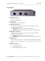
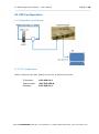
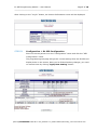
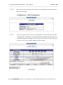
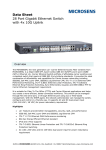
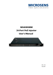
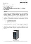
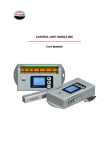
E1 SFP Programming Module User Manual MS100079 ©2014_MICROSENS GmbH & Co. KG_Küferstr. 16_59067 Hamm/Germany_www.microsens.com E1 SFP Programming Module – User Manual Page 2 of 10 ___________________________________________________________________________________________ Caution Circuit/electrical equipment is sensitive to the impact of static electricity, which can endanger their delicate electronics. Dry weather conditions or walking across a carpeted floor may cause you to acquire a static electrical charge. To protect your equipment, please pay attention to the following: Touch the metal chassis of your computer to ground the static electrical charge before you pick up the circuit equipment. Pick up the device by holding it on the left and right edges only. Put on the strap of static-electricity-proof to avoid impacting the function during the equipment is operating. Functional Description The E1 SFP programming module is designed for an engineer to configure and check E1 SFPs parameters via a webpage before they can be installed in the real network for E1 service. It contains 2x Ethernet ports, 1x sub-D9 console port and 1x +5VDC power jack for connecting to an external power adaptor. It is intended for use with E1 SFP MS100070. ©2014_MICROSENS GmbH & Co. KG_Küferstr. 16_59067 Hamm/Germany_www.microsens.com E1 SFP Programming Module – User Manual Page 3 of 10 ___________________________________________________________________________________________ Technical Specifications (1) Physical Dimension Height: 29 mm Width: 158 mm Depth: 114 mm Weight: 0.5 kg (2) LAN and NMS Ethernet Interface a. Compliant with 802.3/802.3u standards b. 100 Base-TX with RJ45 connector c. Full-duplex d. Support Auto-negotiation e. LED indicator for Ethernet: Link status and activity (3) Power Supply a. +5 VDC Power Jack b. Maximum Power Consumption: < 5 watts (4) Operating Environment a. Ambient temperature: 0 ~ 40 ℃ for indoor application b. Storage temperature: 0 ~ 85 ℃ c. Relative humidity: 5 ~ 95% non-condensing ©2014_MICROSENS GmbH & Co. KG_Küferstr. 16_59067 Hamm/Germany_www.microsens.com E1 SFP Programming Module – User Manual Page 4 of 10 ___________________________________________________________________________________________ Front Panel (1) System Indicators PWR (Power on/off LED) ALM (System failures/errors) (2) Reset Button Use this button to restart the system. (3) LAN Ethernet Interface The LAN interface is a RJ45 connector with two LED indicators. Two LED indicators are described below. ORANGE LED: Solid orange indicates Ethernet link is up. GREEN LED: Blinking green indicates Tx/Rx traffic is traversing the port. (4) NMS Ethernet Interface The NMS interface is a RJ45 connector with two LED indicators. Two LED indicators are described below GREEN LED: Solid green indicates Ethernet link is up. ORANGE LED: Blinking orange indicates Tx/Rx traffic is traversing the port. (5) CONSOLE port A RS232 interface with baud-rate 115200bps via DB9 (female)-to-DB9 (male) cable is provided for diagnostic. The user commands (CLI command) are listed in Table 1. (6) +5VDC Power Jack Inner diameter: 2.0 mm Outer diameter: 5.6 mm Center Voltage Polarity: + (Positive) . ©2014_MICROSENS GmbH & Co. KG_Küferstr. 16_59067 Hamm/Germany_www.microsens.com E1 SFP Programming Module – User Manual Page 5 of 10 ___________________________________________________________________________________________ E1 SFP Configuration I. Configuration Architecture II. PC IP configuration Before configuring E1 SFPs, please set your PC IP address as follows: IP Address: 192.168.1.12 Subnet Mask: 255.255.255.0 Gateway: 192.168.1.11 ©2014_MICROSENS GmbH & Co. KG_Küferstr. 16_59067 Hamm/Germany_www.microsens.com E1 SFP Programming Module – User Manual Page 6 of 10 ___________________________________________________________________________________________ III. E1 SFP Configuration STEP I: Invoke the web browser and enter the following URL: http\\:192.168.1.11:6868 STEP II: Key in the user name & password User name: admin Password: microsens ©2014_MICROSENS GmbH & Co. KG_Küferstr. 16_59067 Hamm/Germany_www.microsens.com E1 SFP Programming Module – User Manual Page 7 of 10 ___________________________________________________________________________________________ After clicking on the “Log In” button, the Version Information screen will be displayed. STEP III: Configuration E1 SFP Configuration Move the mouse pointer over the “Configuration” name and click the “SFP Configuration” name. The programming web page will get the current settings from the E1 SFP and display them on the screen. Once you've finished making changes, you need to commit them by clicking “Apply New Setting” button. ©2014_MICROSENS GmbH & Co. KG_Küferstr. 16_59067 Hamm/Germany_www.microsens.com E1 SFP Programming Module – User Manual Page 8 of 10 ___________________________________________________________________________________________ STEP IV: After saving new settings to the E1 SFP, the programming web page will go back to Home page. Configuration SFP Configuration STEP V: Move the mouse pointer over the “Configuration” name and click the “SFP Configuration” name again. The programming web page will read back just saved parameters and display them on the screen. Please check if they are correct or not. If not, please repeat the above steps. ©2014_MICROSENS GmbH & Co. KG_Küferstr. 16_59067 Hamm/Germany_www.microsens.com E1 SFP Programming Module – User Manual Page 9 of 10 ___________________________________________________________________________________________ Command Line Interface for Setup Hyper-terminal as Local Craft Terminal When logging into the Hyper-terminal, set up the craft port as follows: Bit rate: 115200bps Data bit: 8 Parity: none Stop bit: 1 Flow control: none Login password: microsens The CLI commands are summarized as follows: Table 1 CLI Command Description CLI Command Description version Display software version and related information cdisp Display current configurations of the programming box. ipset ip_addr net_mask Set NMS port IP address, subnet mask and gateway address. gw_addr ip_addr: NMS port IP address to be assigned. net_mask: subnet mask of IP address. gw_addr: gateway IP address. Example: ipset 192.168.1.11 255.255.255.0 192.168.1.254 ipget Display NMS port current IP address. upgrade tftp_server_ip Upgrade software image from TFTP server file_name tftp_server_ip: TFTP server IP address file_name: the file name of software image to be upgraded EX: upgrade 192.168.1.12 file_to_be_upgraded.bin ping ip_addr Use ICMP to check connection EX: ping 192.168.1.11 csave Save current configurations to FLASH. logout Logout CLI System ©2014_MICROSENS GmbH & Co. KG_Küferstr. 16_59067 Hamm/Germany_www.microsens.com E1 SFP Programming Module – User Manual Page 10 of 10 ___________________________________________________________________________________________ Disclaimer All information in this document is provided ‘as is’ and subject to change without notice. MICROSENS GmbH & Co. KG disclaims any liability for the correctness, completeness or quality of the information provided, fitness for a particular purpose or consecutive damage. Any product names mentioned herein may be trademarks and/or registered trademarks of their respective companies. ©2014 MICROSENS GmbH & Co. KG, Kueferstr. 16, 59067 Hamm, Germany. All rights reserved. This document in whole or in part may not be duplicated, reproduced, stored or retransmitted without prior written permission of MICROSENS GmbH & Co. KG. Sh/av MS100079_MAN_EN_V1.0.1 ©2014_MICROSENS GmbH & Co. KG_Küferstr. 16_59067 Hamm/Germany_www.microsens.com