1
PAGE
CONTENTS
..........................................................
2
2. POWER ON PREPARATION .... ...... ... .. ...... .. .. .......... .......... ...
3
3. KEYBOARD ........................................... .-.....................
4
4. MORE ABOUT THE KEYBOARD...........................................
5
5. LOADING AND SAVING CASSETTE PROGRAM ..........................
6
6. SYSTEM RESET . . . • . . . . . . . . . . . . . . . . . . . . . . . . . . . . . . . . . . . . . . . . . . . . . . . . . . . . . . . . .
7
7. UTILITY - DUMB TERMINAL, HOST • • .. .. • .. .. .. .. .. •.• .. .. .. .. .. • .. .. .. •
8
1. INTRODUCTION
TABLE OF
CONTENTS
APPENDIX
A. TECHNICAL SPECIFICATIONS ......................... .................. 10
B. MEMORY MAP AND 1/0 MAP
............................................. 12
C. ASCII TABLE •••••••••••••••••••••••••••••••••••••••••••••.••••••.•• 13
I
~-F~.,"Ii
·;u\#
IIi
1
]
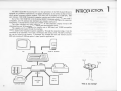
The MKII System 80 microcomputer is a new generation of the MKI System 80 and is
designed for professional applications. Its design philosophy is very similar to that of many
other general purpose computer systems. The main unit is composed of a Z80 CPU, 16K
user memory, 13K ROM, a keyboard, a cassette interface and a video interface.
Out of the 13K ROM, 12K is the Extended BASIC Interpreter which is TRS80 Levell I
compatible, and 1K contains new keyboard and display routines that make the operation
more handy. A dumb terminal routine and a HOST routine are built in.
· The video interface can display upper and lower case characters. Display format is 64
characters/line and 16 lines/screen. The display can automatically scrolls.
The cassette interface operates at a transfer rate of 500 baud, and TRS80 compatible
cassette tapes can be loaded through the interface.
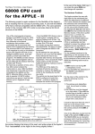
The system also has great expansion capability. Through the expansion edge, it can be
connected to an expander, from which, minifloppy disk drives, printer, RS-232-C interface,
etc, can be linked to the system. The expander can increase the total user memory size to
48K and provide a S-1 00 bus option for users' specific applications.
D
lgJ
CASSETTE RECORDER
VDU
~
INTRODUCTION
I
~
.
=I
~
PRINTER
RS·232-C
ADDITIONAL
SERIAL PORT
c:/-J~
RAM
TELEPHONE MODEM
2
·This is my family!"
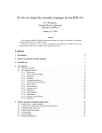
1
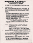
1) Ensure the power switches of the computer and its peripherials are in the 'OFF'
position.
2)
Connect up the cables between the main unit, expander and the peripherials.
3) Turn on power for the
OFF
I~Mil
peripherials first, then the computer.
4)
If your system is not connected to an expander, a message 'READY?' will be displayed
on the top left corner of the screen.
5)
Hit the NEWLINE key, then another READY message should appear on the bottom of
the display.
6) The computer is now in BASIC. To enable your new keyboard and display routines,
type in SYSTEM @EWLINEl
.f.,,, .:.. _______ .'}. •
@
7) The computer prompts with *?.
8)
2
POWER ON
PREB4R4TION
Following is the procedure to set up the system.
D
Enter /12288lNEWLINEI (See Remark)
9) The computer will immediately goes back to READY. You will see a blinking cursor.
MONITOR
10) If minifloppy disk is hooked to the system, do step 6, 7, 8 immediately after entering
Disk Basic.
ON
-*II
+
I
REMARK: See Section 4.4 for other entry points.
(""
I!
NEW LINE
II
...,
....,
READY?
.-.
...
~
"-
.....
READY
:=.. ...
3
KEYBOARD
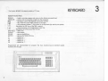
The System 80 MKII Keyboard consists of 71 keys
3
Special Function Keys
BREAK
NEWLINE
-break a running program and return to the Active command level.
-enter a line of command or data into the computer.
I~ I
- backspace, cancel the character previously entered.
~
- tab, move the cursor eight po:>ition to the right.
the computer echoes a [ sign which is an exponent sign used by the system.
(equivalent to ESC key of the MK I system)
[[]
- move the cursor to the beginning of next line.
(equivalent to CTR L key of the V.G.S.)
SHIFTI+---1 -delete line.
CLEAR
- clear screen.
ERASE
-same as thel~lkey.
ENTER
-same as the NEWLINE key.
-default as-.
F1
F2
- defau It as "'- .
-default as ] .
F3
- defau It as /\ .
F4
rn
-
Programmers are recommended to program the four function keys to represent preset
functions for the user.
1
~
~~~~~~~~~~~
lEl8881
4
"]
The key functions mentioned in the previous section are the original functions without
enabling the additional ROM routines, exactly the same as that of the MKI machine. Now,
MKII adds three extra useful functions. They are the automatic key REPEAT,
PRINTSCREEN and SHIFT-LOCK.
MORE ABOUT
THE KEYBOARD
4
4.1 REPEAT KEY
After pressing a key longer than one second, the computer automatically repeats
entering that character until the key is released.
4.2 PRINTSCREEN
Hitting SHIFTP, the computer will transfer the information displayed on the
screen to the printer. If no printer is hooked, the computer will skip the printing process
instead of locking up itself in waiting.
[I] -
4.3 SHIFT LOCK
The new keyboard routine has two input mode: Basic mode and Typewriter mode.
Initially, the Basic mode is set. It looks like an ordinary terminal keyboard. Every
keystroke gives upper case character, but with the SHIFT key depressed, it gives lower case
characters.
To switch the keyboard to the Typewriter mode, hit the SHIFT-[]-Okeys. Then, the
cursor will change from a large block to a small one which indicates that every alphebatic
character input will be of lower case. In this mode, when the SHIFT key is depressed, it
gives upper case characters. However, operation of the numeric keys are the same for both
modes. Hitting a numeric key with the SHIFT key depressed will always give a symbol;
without SHIFT, it is a number.
Switching back to Basic mode from the Typewriter mode, simply hit the SHIFT-III-a
keys again. The cursor will change back to a large block.
4.4 Disable cursor flashing
A flashing cursor can attract the operator's attention, however, somebody may feel it
frustrating.
To disable the flashing cursor, hit SHIFT-BREAK. To enable it, hit SHIFT-BREAK
AGAIN. If you don't want a flashing cursor at the start, you can enter 12299 instead of
12288 described in step 8 of section 2.
NOTE: Sometimes, you may want to neglect the new keyboard routine because of software
compatibility. In such a case, 12294 should be entered in step 8 of section 2.
5
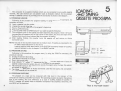
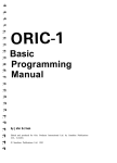
The computer has a cassette interface which can be connected to any audio cassette
recorder. The user therefore can use cassette tapes as cheapest medium for his program
storage. A cassette connector is provided, and the connection is shown in the diagram.
5.1 PROGRAM LOADING
Following is the procedure for program loading. In using the INPUT# command, the
procedure is similar.
a) Insert a cassette into the recorder.
b) Unplug the remote (blue) plug.
c) Wind or Rewind the tape until at the program's beginning.
d) Plug in the remote plug.
e) Enter CLOAD (refer to BASIC manual if you want to specific filename).
f) The computer turns on the cassette and starts searching the program. Once it is found,
two asterisks will appear at the top right corner of the screen, the one at the right will be
flashing from time to time indicating that the program is loading.
g) After loading finishes, the computer turns the cassette off and returns to Active
Command Level.
NOTE: Volume of the recorder should be set to medium level. If loading is unsuccessful, try
to make a small adjustment on the volume.
Loading machine code tape should use the SYSTEM command instead of CLOAD;
users are advised to refer to chapter I of the BASIC manual.
5
LOADING
AND S~ING
OISSETTE PROG~N\.
w-
lrO o
rf'
'j,
·I
a
0000
000
00
0
WHITE
TO
MIC
5.2 PROGRAM SAVING
BLUE
TO
REMOTE
Following is the procedure for program saving. In using the PRINT# command, the
procedure is similar.
a) Unplug the remote (blue) plug.
b) Erase about 5 seconds of the tape.
c) Plug in the remote plug.
d) Enter CSAVE "F", where "F" represents the filename. The user needs not to input the
cassette number since the system can only be connected to one cassette.
e) The computer turns on the cassette and records the program onto the tape. No asterisk
will appear on the screen.
f) The computer goes back to Active Command Level after the saving has completed.
Then, the cassette will be turned off.
BLACK TO
min
VOLUME
EAR
max
5.3 PROGRAM CHECKING
The program on a tape can be compared with that stored in the memory of the
computer by entering a CLOAD? command. The operating procedure is exactly the same as
that of the loading. The only difference is to type in CLOAD? instead of CLOAD. A
READY message will appear when a successful comparison has completed. Otherwise, the
word BAD will be displayed.
6
·That is my heart- beat!!"
The system must, in some cases be reset. When, for example, the machine is running in a
dead loop. The Reset Switch is located at the right side of the bc.ck panel . Pressing the reset
switch causes the computer to return to the 'READY' mode without changing the memory
contents.
The system runs in a dead loop in the following cases:
(1) loading a program from the cassette which contains an invalid file, or when the
volume of the recorder is poorly adjusted.
(2) executing LPRINT or LLIST instructions without hooking up a printer to the
system or having not turned on the printer.
(3) executing an inappropriate POKE instruction.
SYSTEM RESET
6
''I'~
~·
The CPU is reset everytime when the power is on. Turning the system off and on
immediately is not a good practice; because it may cause improper initialization of the CPU .
Therefore, the user should wait for about 15 seconds before turning on the system again.
·Help!'
7
Every computer user should be very familiar with what a terminal is. It is a piece of
equipment for sending data to or retrieving data from the mainframe at a remote location.
Nowadays, nearly all terminals use the same interface standard, that is, RS232C. The
System 80 expander also has an RS232C option. ·
Inside the additional 1 K ROM, a 'dumb terminal' routine is provided. Entering the
routine, the machine will switch itself into a dumb terminal. Every keystroke by the user
'-:Viii be sent out in the form of ASCII code through the RS232C interface. Simultaneously,
every characters received through the interface will be displayed. The keyboard functions
are the same as those discussed in Section 3 and 4 except the repeat key is cancelled. User
can still use the PR INTSCREEN to produce a hardcopy of the information displayed.
Another utility designed to work with Terminal routine is the Host routine. In the Host
mode, resources of the Host computer, such as disk, printer, etc., will be controlled by
commands through the terminal only.
7.1 DUMB TERMINAL
The procedure to enter the routine is:
a) Enter SYSTEM, the computer will response with'*?'.
b) Enter I 13037
c) The computer will ask 'DUPLEX? (F/H): ' ; F stands for Full duplex and H for Half
duplex.
d) Enter 'F' or 'H' to select the desired mode.
e) You are now in the terminal mode.
f) To exit, hit the RESET switch.
g)
8
If a printer is connected, characters displayed will also be output to the printer.
7
UTILITYDUMB TERMINAL,
HOST
7.2 HOST
The HOST routine is a communication routine utilising the RS232C interface. It allows
a Host computer to hook to a remote terminal. The terminal operator can input data to or
retrieve information from the computer. What the terminal is doing will also be displayed on
the Host screen.
Working procedure of the Host user:
1) Enter the Host mode, type in SYSTEM, the computer will display'*?', then enter/12996
2) A message "HOST ENABLE" will send from the Host to the terminal.
3) The Host computer will lock its keyboard up and wait for input from the terminal.
4) If the Host user wants to terminate the Host mode, he should hit the [I) and BREAK
Key simultaneously.
5) A message "HOST/TERMINAL DISCONNECT" will display on both the Host and the
Terminal.
Interconnection
The RS232C signal of the Host and Terminal should be connected in the following way:
Terminal
-Host
--
RxD
TxD
RTS
to
TxD
RxD
CTS
NOTE: The Host entry point 12996 has no line feed on carriage return.
a terminal with no auto line feed. Please enter the Host by 12999.
If you are using
9
{ 1) ELECTRICAL CHARACTERISTICS
POWER CONSUMPTION
-
25W (MAX.)
CASSETTE INPUT LEVEL
-
1 V peak to peak
COMPUTER OUTPUT RECORDING LEVEL
-
0.3 V peak to peak
REMOTE SWITCHING CAPACITY
-
0.5 A max at 6 V DC
VIDEO OUTPUT
-
2V peak to peak
(Negative sync pulse)
APPENDIX A
TECHNICAL
SPECIFIC~TIONS
{2) CONNECTORS PIN ASSIGNMENTS
DIN JACK PIN CONNECTIONS FOR ADDITIONAL CASSETTE
·12 3 4 5 -
REMOTE
SIGNAL GROUND
REMOTE
INPUT
OUTPUT
DIN JACK PIN CONNECTIONS FOR VIDEO INTERFACE
1 - +5
4 5 -
v
VIDEO OUTPUT
GROUND
~=++1------1
3----itKn
DIN JACK
4
5
VIEWED FROM REAR SIDE OF THE SYSTEM
2
EXPANSION PIN EDGE
10
VIEWED FROM REAR SIDE
2
50
1
49
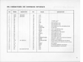
PIN CONNECTIONS FOR EXPANSION INTERFACE
DESCRIPTION
PIN
SIGNAL
1
2
3
4
5
6
7
8
9
10
11
12
13
14
15
16
17
18
19
20
21
22
23
24
25
GND
GND
A7
A6
A5
A4
A1
A3
A2
AO
D5
D2
NC
D1
DO
D3
D7
D6
GROUND
GROUND
vee
+5V SUPPLY
D4
A15
A8
A14
A9
NC
NO CONNECTION
PIN
26
27
28
29
30
31
32
33
34
35
36
37
38
39
40
41
42
43
44
45
46
47
48
49
50
SIGNAL
A10
A13
A 11
A12
PHI
PINT
NC
NC
PHLDA
PHANTOM
-HALT
PWAIT
IORQ
PHOLD
WR
RD
CCDBS/STADBS
MREQ
DODBS/ADDBS
M1
RESET
RFSH
NMI
GND
GND
DESCRIPTION
1. 79 MHz clock
INTERRUPT
NO CONNECTION
NO CONNECTION
PROCESSOR HOLD ACKNOWLEDGE
PHANTOM
HALT ACKNOWLEDGE
PROCESSOR WAIT
INPUT/OUTPUT REQUEST
PROCESSOR HOLD
PROCESSOR WRITE
PROCESSOR READ
CONTROL AND STATUS BUS DISABLE
MEMORY REQUEST
DATA AND ADDRESS BUS Dl SABLE
FIRST STATE OF INSTRUCTION CYCLE
CPU RESET
DYNAMIC MEMORY REFRESH
NON-MASKABLE INTERRUPT
I
1.1
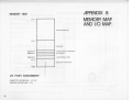
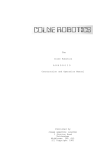
APPENDIX B
MEMORY MAP
AND .I/0 MAP
MEMORY MAP
FFFF
FOR EXPANSION
7FFF
16K RAM
3C00-3FFF
3800-3BFF
VIDEO DISPLAY MEMORY
KEYBOARD
3000-33FF
ADDITIONAL ROM
2FFF
BASIC INTERPRETER
0000
l/0 PORT ASSIGNMENT
CASSETTE INTERFACE- FF, FE
PRINTER INTERFACE- FD
12
~
D
0
0000
1
0001
2
0010
3
0011
4
7
0
1
2
3
4
5
000
001
010
011
100
101
SP
0
®
p
\
p
!
1
A
a
a
q
..
2
B
R
b
r
BREAK
6
110
111
3
c
s
c
s
0100
t+
s
4
D
T
d
t
5
0101
'Yo
5
E
u
e
u
6
0110
&
6
F
v
f
v
7
0111
7
G
w
9
w
8
1000
9
~
{
8
H
X
h
X
1001
~
)
9
I
y
i
y
A
1010
~
J
z
j
z
B
1011
t
+
'
K
[
k
{
C'
1100
FF
HOME
'
<
L
\
I
I
D
1101
CR
-
=
M
]
m
}
E
1110
>
N
t
n
F
1111
?
0
-
0
BS
CLS
*
I
APPENDIX C
ASCII TABLE
~
13
(f)
w
0
z
....
(/J
en
Q
m
z
r
w
(/)
5
z