1
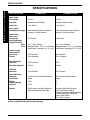
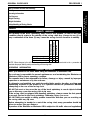
Owner's Operator And Maintenance Manual ® Eliminator Eliminator OSR DEALER: THIS MANUAL MUST BE GIVEN TO THE USER OF THE WHEELCHAIR. USER: BEFORE USING THIS WHEELCHAIR, READ THIS MANUAL AND SAVE FOR FUTURE REFERENCE. WARNING WARNING W A R N I N G DO NOT OPERATE THIS EQUIPMENT WITHOUT FIRST READING AND UNDERSTANDING THIS MANUAL. IF YOU ARE UNABLE TO UNDERSTAND THE WARNINGS AND INSTRUCTIONS, CONTACT A QUALIFIED TECHNICIAN OR TOP END CUSTOMER SUPPORT AT (800) 532-8677 BEFORE ATTEMPTING TO USE THIS EQUIPMENT - OTHERWISE INJURY AND/OR EQUIPMENT DAMAGE MAY RESULT. SPECIAL NOTES WARNING/CAUTION notices as used in this manual apply to hazards or unsafe practices which could result in personal injury or property damage. NOTICE THE INFORMATION CONTAINED IN THIS DOCUMENT IS SUBJECT TO CHANGE WITHOUT NOTICE. RACING CHAIR USER As a manufacturer of racing chairs, Invacare Top End endeavors to supply a wide variety of racing chairs to meet many needs of the end user. However, final selection of the type of racing chair to be used by an individual rests solely with the user and his/her health care professional capable of making such a selection. RACING CHAIR TIE-DOWN RESTRAINTS AND SEAT POSITIONING STRAPS Invacare Top End recommends that racing chair users NOT be transported in vehicles of any kind while in racing chairs. As of this date, the Department of Transportation has not approved any tie-down systems for transportation of a user while in a racing chair, in a moving vehicle of any type. It is Invacare Top End’s position that users of racing chairs should be transferred into appropriate seating in vehicles for transportation and use be made of the restraints made available by the auto industry. Invacare Top End cannot and does not recommend any racing chair transportation systems. AS REGARDS RESTRAINTS - SEAT POSITIONING STRAPS - IT IS THE OBLIGATION OF THE DME DEALER, THERAPISTS AND OTHER HEALTH CARE PROFESSIONALS TO DETERMINE IF A SEATING POSITIONING STRAP IS REQUIRED TO ENSURE THE SAFE OPERATION OF THIS EQUIPMENT BY THE USER. SERIOUS INJURY CAN OCCUR IN THE EVENT OF A FALL FROM A RACING CHAIR. Invacare Top End recommends Seat Positioning Straps. Not only to serve as protection against a fall but also to insure minimal movement in the seat cage. SAVE THESE INSTRUCTIONS. 2 TABLE OF CONTENTS TABLE OF CONTENTS SPECIAL NOTES ..................................................................................................................................... 2 SPECIFICATIONS .................................................................................................................................... 4 PROCEDURE 1 - GENERAL GUIDELINES ............................................................................................. 5 STABILITY ................................................................................................................................................ 5 OPERATING INFORMATION ..................................................................................................................... 5 TIRE PRESSURE AND INFORMATION ..................................................................................................... 6 WEIGHT TRAINING .................................................................................................................................. 6 WEIGHT LIMITATION ................................................................................................................................ 6 SAFETY/HANDLING OF RACING CHAIRS ................................................................................................. 7 PROCEDURE 2 - SAFETY INSPECTION ................................................................................................ 9 SAFETY INSPECTION CHECKLIST .......................................................................................................... 9 TROUBLESHOOTING ........................................................................................................................... 10 MAINTENANCE ...................................................................................................................................... 10 PROCEDURE 3 - UPHOLSTERY/FOOTREST .......................................................................................11 ADJUSTING/REPLACING BACK UPHOLSTERY .......................................................................................11 ADJUSTING/REPLACING LEG CUSHION WITH FOOT POUCH ................................................................11 REPLACING SEAT SLING UPHOLSTERY ............................................................................................... 12 INSTALLING THE PLASTIC FOOTPLATE ................................................................................................ 12 INSTALLING/USING/ADJUSTING THE FIXED FOOTREST ........................................................................ 13 PROCEDURE 4 - WHEELS ................................................................................................................... 14 INSTALLING REAR WHEELS .................................................................................................................. 14 REPAIRING/REPLACING REAR WHEEL TIRE/TUBE .............................................................................. 14 REPLACING PUSHRIMS ........................................................................................................................ 14 INSTALLING/REMOVING FRONT WHEEL ............................................................................................... 14 REMOVING/INSTALLING FORK .............................................................................................................. 15 DETERMINING TOE IN/TOE OUT ........................................................................................................... 16 ADJUSTING TOE IN/TOE OUT - ELIMINATOR ONLY ................................................................................ 16 REPLACING CAMBER INSERTS - ELIMINATOR ONLY ............................................................................ 16 PROCEDURE 5 - COMPENSATOR ...................................................................................................... 17 ADJUSTING COMPENSATOR FOR STRAIGHTS AND TURNS ................................................................ 17 REPLACING COMPENSATOR ............................................................................................................... 17 PROCEDURE 6 - BRAKES ................................................................................................................... 18 ADJUSTING HAND CALIPER BRAKE SENSITIVITY .................................................................................. 18 ADJUSTING/REPLACING HAND CALIPER BRAKE PADS ........................................................................ 18 LIMITED WARRANTY ........................................................................................................................... 19 3 T A B L E O F C O N T E N T S SPECIFICATIONS SPECIFICATIONS S P E C I F I C A T I O N S SPECIFICATIONS ELIMINATOR ELIMINATOR OSR Upper Inside Frame Width: Custom Custom Seat Style: Standard or Kneel Position Standard or Kneel Position Cage Style: I, V or Open V I, V, or Open V Inside seat measurement to allow for hip space - Snug is preferred Inside seat measurement to allow for hip space - Snug is preferred 5 to 8-inches 5 to 8-inches Lower Inside Seat Width (seat cage): Axle Position (from rear of racing chair): Seat Height/Angle (height from floor) Rear: Front: 16, 17, 18 or 19-inches 16, 17, 18, or 19-inches Standard Position - 15, 16, 17, or 18-inches Standard Position - 15, 16, 17, or 18-inches Kneel Position - Seat Angle: 10°, 15°, or 20° Kneel Position - Seat Angle: 10°, 15°, or 20° Overall Length (front wheel to rear wheel): 56 to 74-inches 68 to 74-inches Camber 11 to 15-degrees 11 to 15 degrees Rear Wheel Size (diameter): 700C or 26-inch 700C Rear Axle (diameter): 1/2-inch 1/2-inch Pushrims (diameter): 13 to 16-inches 13 to 16-inches Front Wheel Size (diameter): 18 or 20-inches (20-inches Standard) 20-inches (carbon fiber optional) Hand Brake: Caliper Caliper Weight: Shipping Weight: (approx.)* 17 lbs. 17 27 lbs. 27 Options: Fixed Footrest, Aero Bars, Aluminum Solid Seat, Aluminum Kneel Plate Aluminum Knee Plate, Aluminum Seat, Fixed Footrest, Helmet, Cordless Speedmeter, Additional Straps, Cushion, Racing Suit, Wheel Bag, Carbon Fiber Wheels, Tire Coated Pushrims *60-inch Length Eliminator with complete package. 4 GENERAL GUIDELINES PROCEDURE 1 This Procedure includes the following: Stability Operating Information Tire Pressure Weight Training Weight Limitation Safety/Handling of Racing Chairs STABILITY STABILITY WARNING Knee/Foot Position User Condition Back Upholstery Knee/Foot Position User Condition Back Upholstery The tautness of the back upholstery, knee and/or foot position, as well as the user condition directly relate to the stability of the racing chair. Any change to one (1) or any combination of the three (3) may cause the racing chair to decrease in stability. ● ✓ ✓ ✓ ● ✓ ✓ ✓ ● NOTE: When changes to the left hand column occur, follow across the chart and refer to the ✓ procedure to maintain the proper stability, safety and handling of the racing chair. OPERATING INFORMATION GENERAL WARNINGS Wear your helmet at ALL times when riding the Eliminator or Eliminator OSR. The end-user is responsible for normal maintenance and maintaining the Eliminator or Eliminator OSR in proper operating condition. The manufacturer is not responsible for failure, damage or injury caused by improper operation or maintenance by the end-user. To determine and establish your particular safety limits, practice bending, reaching and transferring activities in the presence of a qualified healthcare professional BEFORE attempting active use of the racing chair. DO NOT sit erect or lean over the top of the back upholstery to reach objects behind you as this may cause the racing chair to tip over. If the racing chair is equipped with kneeling upholstery, always ensure the foot pouch is securely latched to the back upholstery. Otherwise, injury can occur. DO NOT shift your weight or sitting position toward the direction you are reaching as the racing chair may tip over. Before attempting to transfer in or out of the racing chair, every precaution should be taken to reduce the gap distance. Operation of the Eliminator or Eliminator OSR is subject to ALL traffic rules and regulations. 5 G U G I E D N E E L R I A N L E S PROCEDURE 1 GENERAL GUIDELINES GENERAL WARNINGS (CONTINUED) Care must be taken when operating the Eliminator or Eliminator OSR on roads, streets or highways. Give pedestrians the right of way. G U G I E D N E E L R I A N L E S DO NOT climb, go up or down ramps or traverse slopes greater than 9O. DO NOT attempt to move up or down an incline with a water, ice or oil film. NEVER use the hand caliper brake for immediate stops. Using the hand caliper brake for immediate stops can make the front wheel lock up (skid) causing the front tire to blow and go flat. If needing to stop immediately, grab the rear wheels with GLOVED hands. Before using the racing chair, inspect the hand caliper brake and hand caliper brake pads for proper operation and wear. Replace if worn. DO NOT attempt to ride over curbs or obstacles. Doing so may cause your racing chair to turn over and cause bodily harm or damage to the racing chair. DO NOT use parts, accessories, or adapters other than those authorized by Invacare Top End. DO NOT stand or transfer on the frame of the racing chair. Invacare strongly recommends that the racing chair be boxed or otherwise protected before transporting by an airline carrier. DO NOT use racing chair on an indoor training roller, otherwise the warranty will be void. TIRE PRESSURE AND INFORMATION DO NOT use your racing chair unless it has the proper tire pressure (p.s.i.). DO NOT overinflate the tires. Refer to manufacturers recommendations on the sidewall of the tire. Failure to follow these suggestions may cause the tire to explode and cause bodily harm. DO NOT continue using your racing chair if tires are bare or flat. The racing chair is not stable with bare or flat tires, as tire may roll off and cause the racing chair to crash. Bare tires may result in a flat which may cause the racing chair to crash or veer to one side. CORIMA CARBON FIBER WHEELS ONLY - Corima Wheels MUST NOT be used when tires are bare or flat. If a flat wheel occurs, STOP IMMEDIATELY. Otherwise, the wheel warranty will be void. WEIGHT TRAINING Invacare Top End DOES NOT recommend the use of its racing chairs as a weight training apparatus. Invacare Top End racing chairs have NOT been designed or tested as a seat for any kind of weight training. If occupant uses said racing chair as a weight training apparatus, Invacare Top End shall NOT be liable for bodily injury and the warranty will be voided immediately. WEIGHT LIMITATION The Invacare Top End Eliminator and Eliminator OSR chairs have a weight limitation of 250 lbs. (113.5 kg.). 6 GENERAL GUIDELINES PROCEDURE 1 Also, be aware of any removable (detachable) parts. These must NEVER be used for hand-hold or lifting supports, as they may be inadvertently released, resulting in possible injury to the user and/or assistant(s). SAFETY/HANDLING OF RACING CHAIRS “Safety and Handling” of the racing chair requires the close attention of the racing chair user as well as the assistant. This manual points out the most common procedures and techniques involved in the safe operation and maintenance of the racing chair. It is important to practice and master these safe techniques until you are comfortable in maneuvering around the frequently encountered architectural barriers. Use this information only as a “basic” guide. The techniques that are discussed on the following pages have been used successfully by many. Individual racing chair users often develop skills to deal with daily living activities that may differ from those described in this manual. Invacare Top End recognizes and encourages each individual to try what works best for him/her in overcoming architectural obstacles that they may encounter however, ALL WARNINGS and CAUTIONS given in this manual MUST be followed. Techniques in this manual are a starting point for the new racing chair user and Assistant with “safety” as the most important consideration for all. When learning a new assistance technique, have an experienced assistant help you before attempting it alone. Percentage of Weight Distribution WARNING The tautness of the back upholstery, knee and/or foot position, as well as the user condition directly relate to the stability of the racing chair. Any change to one (1) or any combination of the three (3) may cause the racing chair to decrease in stability. Many activities require the racing chair owner to reach, bend and transfer in and out of the racing chair. These movements will cause a change to the normal balance, the center of gravity, and the weight distribution of the racing chair. To determine and establish your particular safety limits, practice bending, reaching and transferring activities in several combinations in the presence of a qualified healthcare professional BEFORE attempting active use of the racing chair. Proper positioning is essential for your safety and performance of the racing chair. Stability and Balance To assure stability and proper operation of your racing chair, you must at all times wear your seat positioning strap and maintain proper balance. Your racing chair has been designed to remain upright and stable during normal racing/training activities as long as you do not move beyond the center of gravity. Hand Caliper Brake WARNING WARNING DO NOT shift your weight or sitting position toward the direction you are reaching as the racing chair may tip over. NEVER use the hand caliper brake for immediate stops. Using the hand caliper brake for immediate stops can make the front wheel lock up (skid) causing the front tire to blow and go flat. If needing to stop immediately, grab the wheels with GLOVED hands. Virtually all activities which involve movement in the racing chair have an effect on the center of gravity. A Note to Racing Chair Assistants The hand caliper brake is designed for managing safe operation of the racing chair at speeds greater than ten (10) m.p.h. When learning assistance techniques for the Eliminator or Eliminator OSR, have an experienced assistant help you before attempting it alone. When you are assisting with the Eliminator or Eliminator OSR remember to use good body mechanics. Keep your back straight and bend your knees whenever lifting or positioning the Eliminator or Eliminator OSR for the end-user. Transferring To and From Other Seats WARNING BEFORE attempting to transfer in or out of the racing chair, every precaution should be taken to reduce the gap distance. The tautness of the back upholstery, knee and/or foot position, as well as the user condition directly relate to the stability of the racing chair. Any change to one (1) or any combination of the three (3) may cause the racing chair to decrease in stability. KNEELING SEAT UPHOLSTERY: Ensure that feet slide evenly into the foot pouch and avoid the rear wheel spokes. Ensure that the foot pouch is securely latched to the back upholstery. Otherwise, injury can occur. WARNING DO NOT attempt to lift a racing chair by lifting on any removable (detachable) parts. Lifting by means of any removable (detachable) parts of a racing chair may result in injury to the user or damage to the racing chair. 7 G U G I E D N E E L R I A N L E S PROCEDURE 1 GENERAL GUIDELINES NOTE: Invacare Top End strongly recommends an experienced assistant help in the transferring to and from the racing chair. The assistant should hold down the front of the racing chair to avoid any instability that may occur. NOTE: Once seated in the racing chair, move your feet back as close as possible to the axle as you feel comfortable and tighten the knee strap. KNEELING UPHOLSTERY TRANSFER G EG NU E I RD AE LL I N E S STEP 2: Place LEFT leg on top of the LEFT cage frame. STEP 3: Start RIGHT leg into the kneeling upholstery and UNDER the seat sling. STEP 4: Start LEFT leg into the kneeling upholstery and UNDER the seat sling. STEP 1: Shift body weight to the edge of the wheelchair upholstery closest to the racing chair. STEP 7: Strap the knees up into a safe and comfortable position. STEP 6: Strap feet onto the footplate. Position the chair as close as possible along side the seat to which you are transferring. Shift body weight into seat with transfer. STEP 7: Lift and shift weight into racing chair upholstery. STEP 5: Place LEFT hand on the frame cage. Reaching, Bending - Backwards WARNING DO NOT sit erect or lean over the top of the back upholstery. This will change your center of gravity and may cause you to tip over. STEP 6: Place RIGHT hand on the racing chair frame. DO THIS NOTE: Some racers will rest on the frame cage of the racing chair half way through the transfer and move the RIGHT hand to the right side of the frame. STANDARD UPHOLSTERY TRANSFER STEP 2: Place LEFT leg through the opening in the frame cage. STEP 1: Shift body weight to the edge of the racing chair upholstery closest to the racing chair. NOT THIS STEP 3: Place LEFT hand on the frame cage. STEP 4: Place RIGHT hand on the wheelchair frame. STEP 5: Lift and shift weight into racing chair upholstery. Position racing chair as close as possible to the desired object. Reach back only as far as your arm will extend without changing your sitting position. NOTE: Some racers will rest on the frame cage of the racing chair half way through the transfer and move the RIGHT hand to the right side of the frame. 8 SAFETY INSPECTION PROCEDURE 2 NOTE: Every six (6) months or as necessary take your racing chair to a qualified technician for a thorSafety Inspection Checklist ough inspection and servicing. Regular cleaning will reveal loose or worn parts and enhance the smooth Troubleshooting operation of your racing chair. To operate properly and Maintenance safely, your racing chair must be cared for just like any other vehicle. Routine maintenance will extend the SAFETY INSPECTION CHECKLIST life and efficiency of your racing chair. Initial adjustments should be made to suit your personal body structure and preference. Thereafter follow these maintenance procedures. This Procedure includes the following: ITEM INITIALLY INSPECT/ ADJUST WEEKLY INSPECT/ ADJUST MONTHLY INSPECT/ ADJUST PERIODICALLY GENERAL Racing chair rolls straight (no excessive drag or pull to one side). X X SEAT AND BACK UPHOLSTERY Inspect for rips or sagging. X X REAR WHEELS Axles are securely tightened. No excessive side movement or binding when lifted and spun. CAUTION: As with any vehicle, the wheels and tires should be checked periodically for cracks and wear, and should be replaced. X X X X X X PUSHRIMS Inspect for signs of rough edges or peeling of tire/tape coating where it might separate from the pushrim. X X SPOKES Inspect for bent or broken spokes. All spokes uniformly tight. X X X X X X FRONT WHEEL Inspect wheel/fork assembly for proper tension by front wheel; front wheel should come to a gradual stop. Loosen/tighten allen screws if wheel wobbles noticeably or binds to a stop. NOTE: There WILL be some play in the front wheel- This is common in all front hubs. Wheel bearings are clean and free of moisture. CAUTION: As with any vehicle, the wheels and tires should be checked periodically for cracks and wear, and should be replaced. HAND CALIPER BRAKE Does not interfere with front wheel when rolling. Hand caliper brake is easy to engage. No excessive wear of hand caliper brake pads. TIRES Inspect for flat spots and wear. Check pneumatic tires for proper inflation. Check frame cage for interference with tires. CAUTION: As with any vehicle, the wheels and tires should be checked periodically for cracks and wear, and should be replaced. X X X X X X X X X X X CLEANING Clean upholstery with light detergent and water. X 9 X X X X X X X I N SS AP FE EC TT Y I O N PROCEDURE 2 SAFETY INSPECTION TROUBLESHOOTING TROUBLESHOOTING GUIDE MECHANICAL I N SS AP FE EC TT Y I O N CHAIR VEERS RIGHT CHAIR VEERS LEFT X X SLUGGISH SQUEAKS TURN OR AND PERFORMANCE RATTLES X X X LOOSENESS IN CHAIR X SOLUTIONS Check tires for correct and equal pressure. X X Check for loose stem nuts. X X Check spokes and nipples. X Adjust compensator (Procedure 5). X Check toe in/toe out. 3. Check tires for proper pressure and if not inflated properly, inflate to recommended tire pressure listed on the side wall of the tire. MAINTENANCE Maintenance Safety Precautions 4. The wheels and tires should be checked periodically for cracks and wear, and should be replaced by a qualified technician. WARNING After making adjustments, always make sure that parts are properly tightened BEFORE using the racing chair. CAUTION 5. Regularly check for loose spokes in the rear and front wheels. If loose, have them adjusted by a qualified technician. DO NOT overtighten hardware attaching to the frame. This could cause damage to the frame tubing. 6. Periodically check pushrims to ensure they are secured to the rear wheels. Refer to REPLACING PUSHRIMS in PROCEDURE 2 of this manual. 7. Periodically adjust hand caliper brake in correlation to hand caliper brake pad wear. Refer to ADJUSTING HAND CALIPER BRAKE SENSITIVITY/REPLACING HAND CALIPER BRAKE in PROCEDURE 4 of this manual. Suggested Maintenance Procedures 1. Before using your Invacare Top End Eliminator or Eliminator OSR, check all parts for damage or wear and replace, if necessary. Check all parts for proper adjustment. 8. Periodically check rear and front wheel bearings to make sure they are clean and free from moisture. ® Use a Teflon lubricant if necessary. 2. Keep axles free of dirt and lint to ensure proper fit in axle receiver. Cross threading will damage the axles and axle receivers. 9. Check upholstery for sagging, rips or tears. WARNING DO NOT use the racing chair unless it has the proper tire pressure (p.s.i.). DO NOT overinflate the tires. Failure to follow manufacturers recommendations listed on the side wall of the tire may cause the tire to explode and cause bodily harm. 10 UPHOLSTERY/FOOTREST PROCEDURE 3 7. If the racing chair is equipped with kneeling upholstery, attach the foot pouch to the back upholstery and adjust. Refer to ADJUSTING/REPLACING LEG CUSHION WITH FOOT POUCH in this procedure of the manual. This Procedure includes the following: Adjusting/Replacing Back Upholstery Adjusting/Replacing Leg Cushion with Foot Pouch Replacing Seat Sling Upholstery Installing the Plastic Footplate Installing/Using/Adjusting the Fixed Footrest Slots WARNING After ANY adjustments, repair or service and BEFORE use, make sure all attachment hardware is tightened securely - otherwise, injury or damage may result. The tautness of the back upholstery, knee and/or foot position, as well as the user condition directly relate to the stability of the racing chair. Any change to one (1) or any combination of the three (3) may cause the racing chair to decrease in stability. Refer to STABILITY in PROCEDURE 1 of this manual. Fastening Flaps Foot Pouch Attaches Here Bottom of Back Upholstery U P H O L S T E R Y Back Upholstery Seat Cushion Seat Sling Upholstery ADJUSTING/REPLACING BACK UPHOLSTERY (FIGURE 1) 1. Unlatch the three (3) fastening flaps that secure the back upholstery to the racing chair frame. Adjusting Foot Pouch 1. Adjust back upholstery to the desired tautness. FIGURE 1 - ADJUSTING/REPLACING BACK UPHOLSTERY TIGHTER upholstery will increase the stability and maintain normal maneuverability of the racing chair because the user is pushed forward in the racing chair slightly. LOOSER upholstery will increase the maneuverability and make the racing chair less stable because additional weight is being distributed onto the rear wheels. ADJUSTING/REPLACING LEG CUSHION WITH FOOT POUCH (FIGURE 2) Replacing WARNING 1. Unlatch the foot pouch of the leg cushion from the back upholstery (kneeling upholstery only). If the racing chair is equipped with kneeling upholstery, always ensure the foot pouch is securely latched to the back upholstery. Otherwise, injury can occur. 2. Unlatch the bottom of the back upholstery from the seat sling upholstery. 3. Remove the existing back upholstery from the racing chair. Adjusting 4. Feed the top two (2) fastening flaps of the new back upholstery through the slots on the racing chair frame. 1. Adjust leg cushion w/foot pouch to the desired tautness. 5. Feed the bottom fastening flap of the new back upholstery between the racing chair frame and the clothing guards. 6. Adjust the new back upholstery for desired tautness. Refer to ADJUSTING BACK UPHOLSTERY in this procedure of the manual. 11 F O O T R E S T PROCEDURE 3 Foam Insert U P H O L S T E R Y UPHOLSTERY/FOOTREST 4. Remove seat cushion from the seat sling upholstery. Seat Sling Upholstery 5. Unlatch the fastening flap that secures the existing seat upholstery to itself. 6. Slide the ends of the existing seat upholstery up and through the frame of the racing chair. Back Upholstery 7. Slide the new upholstery through the frame of the racing chair as shown in FIGURE 5. 8. Pull the seat upholstery to the desired tautness and secure with the fastening flap. Foot Pouch 9. Reverse STEPS 1-5 to reassemble. Slots Racing Chair Frame Seat Upholstery Fastening Flaps FIGURE 2 - ADJUSTING/REPLACING LEG CUSHION WITH FOOT POUCH Fastening Flap Replacing 1. Unlatch the three (3) fastening flaps that secure the leg cushion to the racing chair frame. F O O T R E S T FIGURE 3 - REPLACING SEAT SLING UPHOLSTERY 2. Unlatch the foot pouch from the back upholstery. INSTALLING THE PLASTIC FOOTPLATE (FIGURE 4) 3. Remove the existing leg cushion w/foot pouch. 4. Install the new leg cushion w/foot pouch. 5. Feed the top two (2) fastening flaps of the new leg cushion w/foot pouch through the slots on the racing chair frame. WARNING Feet MUST be secured against the plastic footplate BEFORE using racing chair. Otherwise, injury or damage may occur. 6. Feed the bottom fastening flap between the side guard and the racing chair frame and secure together. 1. Secure the fastening straps around the frame as shown in FIGURE 4. 7. Attach the foot pouch to the back upholstery and adjust to the desired tautness. Refer to ADJUSTING LEG CUSHION WITH FOOT POUCH in this procedure of the manual. 2. Place feet onto plastic footplate where indicated in FIGURE 4. NOTE: It may be necessary to loosen or tighten the fastening straps for comfort and to secure feet to the footplate. REPLACING SEAT SLING UPHOLSTERY (FIGURE 3) 3. Secure ankles with ankle strap by wrapping strap around ankles. 1. Unlatch the foot pouch from the back upholstery. 2. Unlatch the bottom of the back upholstery from the underside of the seat sling upholstery. 3. Unlatch the top two (2) fastening flaps that secure the leg cushion to the racing chair frame. 12 UPHOLSTERY/FOOTREST PROCEDURE 3 3. Tighten the set screw to secure the upper and lower footrest support tubes. Seat Fastening Strap ANGLE. 1. Loosen the locknuts securing the footplate mounting bracket. Plastic Footplate Frame 2. Adjust the angle of the footplate as desired. 3. Tighten the locknuts securing the footplate mounting bracket. DEPTH. 1. Remove the locknuts and hex screws securing the footplate mounting bracket. Ankle Strap 2. Reposition the footplate to the desired set of mounting holes (DETAIL "A"). Fastening Strap 3. Install the hex screws through the footplate, footstrap and footplate mounting bracket. Place Feet HERE U P H O L S T E R Y 4. Secure the hex screws with the locknuts. Tighten securely. FIGURE 4 - INSTALLING THE PLASTIC FOOTPLATE Hex Screw INSTALLING/USING/ADJUSTING THE FIXED FOOTREST (FIGURE 5) Racing Chair Frame Mounting Bracket Set Screw Upper Support Tube Lower Support Tube WARNING Feet MUST be secured into the fixed footrest BEFORE using racing chair. Otherwise, injury or damage may occur. Footplate Foot Strap Ankle Strap Installing/Using Fixed Footrest 1. Remove the hex screws from the mounting bracket. Buckle Hex Screw Locknut 2. Position the upper support tube on the underside of the racing chair frame. 3. Position the mounting bracket on top of the racing chair frame. Footplate Mounting Bracket DETAIL "A" - ADJUSTING DEPTH 4. Install the hex screws to secure the mounting bracket to the upper support tube. Hex Screws 6. If necessary, adjust footrest. Refer to ADJUSTING FIXED FOOTREST in this procedure. Footplate 7. Pull the buckle out to release foot strap. Mounting Holes 8. Place feet onto footrests. 9. Pull end of foot strap to tighten. 10. Close buckle to secure foot strap and feet to footplate. 11. Secure ankles by wrapping ankle strap around lower footrest support tube and ankles. FIGURE 5 - INSTALLING/USING/ ADJUSTING THE FIXED FOOTREST Adjusting Fixed Footrest HEIGHT. 1. Loosen the set screw securing the upper and lower footrest support tubes. 2. Reposition the footrest up or down as desired. 13 F O O T R E S T PROCEDURE 4 W H E E L S WHEELS REPAIRING, REPLACING REAR WHEEL TIRE/TUBE This Procedure includes the following: Installing Rear Wheels Repairing, Replacing Rear Wheel Tire/Tube Replacing Pushrims Installing/Removing Front Wheel Removing/Installing Fork Determining Toe In/ Toe Out Adjusting Toe In/Toe Out - Eliminator Only Replacing Camber Inserts - Eliminator Only WARNING Replacement of a clincher tire or tube MUST be performed by a qualified technician. NOTE: TUBULAR TIRES are tires with tubes sewn into the tires, they are high pressure (140+ lbs. psi) and must be glued to the rim. Once they have a hole in them, they must be replaced. Also, tubular tires will lose air overnight, but they are not faulty. This is a characteristic of tubular tires. Tubular tires do not fit on a clincher rim. NOTE: CLINCHER TIRES are like conventional bicycle tires, there is an inner tube separate from the actual tire. They are more durable for longer periods of time and if punctured the tube can be replaced (by a qualified technician) and the tire will still be in tact. Clincher tires use 100+ lbs. psi. Clincher tires do not fit on a tubular rim. WARNING After ANY adjustments, repair or service and BEFORE use, make sure all attachment hardware is tightened securely - otherwise, injury or damage may result. INSTALLING REAR WHEELS (FIGURE 1) REPLACING PUSHRIMS (FIGURE 2) NOTE: There is a RIGHT and LEFT rear wheel. The pushrims should be pushing onto the spokes at the top of the rear wheel. 1. Determine the right and left rear wheel. 2. Apply a small amount of grease onto the axle. 3. Insert axle into the axle tube on the racing chair frame. 4. Securely tighten the axle to the racing chair frame using the allen wrench. 2. Loosen the allen screws that secure the existing pushrim to the rear wheel. 1. Remove the rear wheel from the racing chair. FRONT OF RACING CHAIR 3. Remove the existing pushrim. 4. Install the new pushrim onto the rear wheel and securely tighten the allen screws. NOTE: Ensure the rim is pushing onto the spokes at the top of the rear wheel. 5. Reinstall rear wheel onto the racing chair. Spoke FRONT OF RACING CHAIR Pushrim Spokes Allen Wrench Allen Screw Allen Wrench Spokes Pushrim FIGURE 2 - REPLACING PUSHRIMS INSTALLING/REMOVING FRONT WHEEL (FIGURE 3) Axle Tube Rear Wheel FIGURE 1 - INSTALLING REAR WHEELS NOTE: To remove, reverse the order of the steps below. NOTE: There WILL be some play in the front wheel. This is common in all front hubs. 1. Remove the two (2) hex axles from the front wheel. 2. Line up the mounting holes in the front wheel with the holes in the forks. 3. Reinstall the (2) hex axles and securely tighten the front wheel to the fork. 14 WHEELS Hex Axle PROCEDURE 4 5. Install headset onto new/existing fork stem. Refer to FIGURE 4. Hex Axle 6. Install socket screw through mounting hole in headset and tighten securely. Front Wheel 7. Remove the locknut that secures the steering cylinder to the front fork. Fork 8. Install the steering cylinder onto the front fork and securely tighten with the locknut. FIGURE 3 - INSTALLING/REMOVING FRONT WHEEL 9. If equipped, line up the custom steering handle with the racing chair frame and tighten the socket screw securely. REMOVING/INSTALLING FORK (FIGURE 4) Socket Screw Steering Cylinder Removing 1. Remove the two (2) hex axles that secure front wheel to existing fork and remove front wheel from the racing chair. Locknut 2. Remove the locknut that secures the steering cylinder to the exisiting fork and remove the steering cylinder from the fork. Metal Washers 3. Remove the socket screw that secures the headset to the exisiting fork stem. Spacer Headset Needle Bearing TOP 4. If equipped, loosen the socket screw that secures the custom steering handle to the existing fork as shown in DETAIL "A" of FIGURE 4. Head Tube 5. Remove the headset, custom steering handle (if equipped), TOP metal washer, needle bearing, metal washer and spacer from the exisiting fork stem. Spacer Metal Washers 6. Slide existing fork stem out of head tube of the racing chair. 7. Remove BOTTOM metal washer, needle bearing, metal washer and spacer from the existing fork stem. Fork Stem Needle Bearing BOTTOM Installing 1. Install the BOTTOM metal washer, needle bearing, metal washer and spacer onto the new/existing fork stem. Refer to FIGURE 4. DETAIL "A" 2. Slide new/existing fork stem into head tube of racing chair. 3. Install TOP spacer, metal washer, needle bearing and metal washer onto new/existing fork stem. Refer to FIGURE 4. Socket Screw Headset 4. If equipped, install custom steering handle onto new/ existing fork stem. Refer to DETAIL "A" of FIGURE 4. Fork Stem Custom Steering Handle FIGURE 4 - REMOVING/INSTALLING FORK 15 W H E E L S PROCEDURE 4 WHEELS 4. If the difference between the measurements is greater than 1/2-inch, correct the toe-in/toe-out condition. Refer to ADJUSTING TOE-IN/TOE-OUT - ELIMINATOR ONLY in this procedure of the manual. DETERMINING TOE IN/TOE OUT (FIGURE 5) 1. Inflate all pneumatic tires to recommended tire pressures. W H E E L S NOTE: Recommended air pressure is listed on the sidewall of the tire. 2. Measure the distance between the center lines at the rear and front of the rear wheels at approximately 12-inches from the ground/floor. NOTE: For optimum accuracy, perform STEP 2 with the racing chair occupied. 3. Determine the difference between the two (2) measurements. If the difference between the two (2) measurements is GREATER than 1/2-inch (0 + 1/4-inch for maximum rollability), one (1) of two (2) conditions exists: a. If the rear centerline measurement of the rear wheels is SMALLER than the front centerline measurement of the rear wheels, a TOE-OUT condition exists (FIGURE 5). b. If the rear centerline measurement of the rear wheels is LARGER than the front centerline measurement of the rear wheels, a TOE-IN condition exists (FIGURE 5). ADJUSTING TOE IN/TOE OUT ELIMINATOR ONLY (FIGURE 6) 1. Loosen, but do not remove the two (2) socket screws and clamps that secure the two (2) camber inserts to the camber bar. 2. Slowly rotate the camber insert CLOCKWISE or COUNTERCLOCKWISE until the rear wheels are approximately in a straight line. 3. Securely tighten the socket screws and clamps that secure the camber inserts to the camber bar. 4. Measure the distance between the center lines at the rear and front of the rear wheels at approximately 12inches from the ground/floor. Refer to DETERMINING TOE IN/TOE OUT in this procedure of the manual. 5. Repeat STEPS 1-4 until the toe in/toe out measurement is less than 1/2-inch (0 + 1/4-inch for maximum rollability). Clamp FRONT OF RACING CHAIR Camber Insert Toe-out Toe-in Socket Screw Camber Bar FIGURE 6 - ADJUSTING TOE IN/TOE OUT ELIMINATOR ONLY / REPLACING CAMBER INSERTS ELIMINATOR ONLY Front Centerline REPLACING CAMBER INSERTS ELIMINATOR ONLY (FIGURE 6) Top View of Racing chair 1. Loosen, but do not remove the socket screws and clamps that secure the camber inserts to camber bar. 2. Remove existing camber insert from the camber bar. Rear Centerline 3. Install the new camber insert into the camber bar. 4. Adjust the toe in/toe out of the racing chair. Refer to DETERMINING TOE IN/TOE OUT in this procedure of the manual. Smaller Than Front Larger Than Front FIGURE 5 - DETERMINING TOE IN/TOE OUT 16 COMPENSATOR PROCEDURE 5 REPLACING COMPENSATOR (FIGURE 2) This Procedure includes the following: Adjusting Compensator for Straights and Turns Replacing Compensator CAUTION The track stops are spring loaded. Use caution when removing. WARNING After ANY adjustments, repair or service and BEFORE use, make sure all attachment hardware is tightened securely - otherwise, injury or damage may result. 1. Remove the locknut that secures the steering cylinder to the compensator. 2. Remove the two (2) locknuts and washer that secure the compensator to the racing chair frame. 3. Remove the compensator from the racing chair frame. ADJUSTING COMPENSATOR FOR STRAIGHTS AND TURNS (FIGURE 1) 4. Remove the two (2) track stops from the compensator by using the following steps: NOTE: Adjustments to the compensator should be made while sitting in the racing chair. NOTE: Different speeds will affect the way racing chair handles. Therefore, it is critical for maximum performance to set compensator close to expected race speed. Keep in mind that all tracks are different. Also, different conditions will affect the way racing chair handles. Extreme crosswinds should be taken into consideration. A. Remove the locknut on the track stop screws. B. Remove track stop screw and spring from compensator. 5. Install new compensator by reversing STEPS 1-4. 6. Adjust the compensator. Refer to ADJUSTING COMPENSATOR FOR STRAIGHTS AND TURNS in this procedure of the manual. NOTE: The procedures below are for a counter-clockwise racing track. Reverse the Right and Left instructions for a clockwise racing track. Straights While Racing or Training Compensator Racing Chair Frame 1. Turn front wheel until it is approximately in a straight line. 2. Turn the RIGHT track stop screw until the locknut on the track stop is touching the racing chair frame. Steering Cylinder 3. Repeat STEPS 1-2 until racing chair follows a straight line. Washer Locknuts Locknut TRACK STOPS Turns While Racing or Training Track Stop Screw 1. Turn front wheel until in required position for desired turn. Track Stop Screw 2. Turn the LEFT track stop screw until it is touching the racing chair frame. 3. Repeat STEPS 1-2 until racing chair follows the desired turn. FRONT OF RACING Racing Chair CHAIR Frame Track Stop Screw (straights) Track Stop Screw (turns) TOP VIEW OF Locknuts RACING CHAIR FIGURE 1 - ADJUSTING COMPENSATOR FOR STRAIGHTS AND TURNS Compensator 17 Locknuts FIGURE 2 - REPLACING COMPENSATOR C O M P E N S A T O R PROCEDURE 6 BRAKES ADJUSTING/REPLACING HAND CALIPER BRAKE PADS (FIGURE 2) This Procedure includes the following: Adjusting Hand Caliper Brake Sensitivity Adjusting/Replacing Hand Caliper Brake Pads WARNING Before using the racing chair, inspect the hand caliper brake and hand caliper brake pads for proper operation and wear. Replace if worn. WARNING B R A K E S After ANY adjustments, repair or service and BEFORE use,makesure all attachment hardware is tightened securely - otherwise, injury or damage may result. Adjusting Hand Caliper Brake Pads 1. Loosen the allen screw that secures the hand caliper brake pad to the hand caliper brake. Replacement of the hand caliper brake MUST be performed by a qualified technician. 2. Position the hand caliper brake pad until it is in-line with the rim of the front wheel. ADJUSTING HAND CALIPER BRAKE SENSITIVITY (FIGURE 1) 3. Securely tighten the allen screw that secures the hand caliper brake pad to the hand caliper brake. WARNING 4. Repeat the above steps for the opposite side. Before using the racing chair, inspect the hand caliper brake and hand caliper brake pads for proper operation and wear. Replace if worn. 5. Adjust hand caliper brake. Refer to ADJUSTING HAND CALIPER BRAKE SENSITIVITY in this procedure of the manual. Adjusting Hand Caliper Brake Sensitivity Replacing Hand Caliper Brake Pads 1. Loosen the allen screw that maintains the tautness of the hand caliper brake cable. NOTE: Invacare Top End recommends replacing BOTH hand caliper brake pads at the same time to achieve the best hand caliper brake performance possible. 2. Squeeze both hand caliper brake pads with your hand to adjust the hand caliper brake cable. 1. Remove the front wheel. Refer to INSTALLING/REMOVING FRONT WHEEL in PROCEDURE 4 of this manual. 3. Loosely tighten the allen screw to ensure that the hand caliper brakes are adjusted properly. 2. Remove allen screw and washer that secure the existing hand caliper brake pad to the hand caliper brake. NOTE: When the hand caliper brake is engaged, the hand caliper brake pads should rest solely on the rim of the wheel. If not, adjust the hand caliper brake pads. Refer to ADJUSTING HAND CALIPER BRAKE PADS in this procedure of the manual. 4. Repeat the above steps until the hand caliper brakes are adjusted properly. 5. Securely tighten the allen screw that maintains the tautness of the hand caliper brake cable. 3. Install the NEW hand caliper brake pad with the arrow pointing towards the front of the racing chair with the existing hardware. NOTE: The arrow pointing towards the front of the racing chair determines the right and left hand caliper brake pad. 4. Repeat above steps for opposite brake pad. 5. Reinstall the front wheel onto the racing chair. Refer to INSTALLING/REMOVING FRONT WHEEL in PROCEDURE 4 of this manual. 6. Adjust the hand caliper brake pads. Refer to ADJUSTING HAND CALIPER BRAKE PADS in this procedure of the manual. Hand Caliper Brake Pad Hand Caliper Brake Pad Tire Hand Caliper Brake Cable Allen Screw FIGURE 1 - ADJUSTING HAND CALIPER BRAKE SENSITIVITY Washer Arrow Allen Rim Allen Screw Screw ADJUSTING REPLACING FIGURE 2 - ADJUSTING/REPLACING HAND CALIPER BRAKE PADS 18 WARRANTY LIMITED WARRANTY PLEASE NOTE: THE WARRANTY BELOW HAS BEEN DRAFTED TO COMPLY WITH FEDERAL LAW APPLICABLE TO PRODUCTS MANUFACTURED AFTER JULY 4, 1975. This warranty is extended only to the original purchaser/user of our products. This warranty gives you specific legal rights and you may also have other legal rights which vary from state to state. Invacare warrants the Eliminator/Eliminator OSR frame to be free from defects in materials and workmanship for a period of two (2) years from date of purchase to the original owner. All component parts including, but not limited to camber tubes, compensator, and upholstery are warranted against defects in materials and workmanship for a period of one (1) year from the original invoice date except steering cylinders, cushion, bushings, bearings, cables and tires/tubes. Carbon fiber wheels are subject to the wheel manufacturer's warranty and are not warranted by Invacare. If within such warranty period any such product shall be proven to be defective, such product shall be repaired or replaced, at Invacare's option. This warranty does not include any labor or shipping charges incurred in replacement part installation or repair of any such product. Invacare's sole obligation and your exclusive remedy under this warranty shall be limited to such repair and/or replacement. For warranty service, please contact the dealer from whom you purchased your Invacare product. In the event you do not receive satisfactory warranty service, please write directly to Invacare at the address below. Provide dealer’s name, address, date of purchase, indicate nature of the defect and, if the product is serialized, indicate the serial number. Do not return products to our factory without our prior consent. LIMITATIONS AND EXCLUSIONS: THE FOREGOING WARRANTY SHALL NOT APPLY TO SERIAL NUMBERED PRODUCTS IF THE SERIAL NUMBER HAS BEEN REMOVED OR DEFACED, PRODUCTS SUBJECTED TO NEGLIGENCE, ACCIDENT, IMPROPER OPERATION, MAINTENANCE OR STORAGE, COMMERCIAL OR INSTITUTIONAL USE, PRODUCTS MODIFIED WITHOUT INVACARE'S EXPRESS WRITTEN CONSENT (INCLUDING, BUT NOT LIMITED TO, MODIFICATION THROUGH THE USE OF UNAUTHORIZED PARTS OR ATTACHMENTS; PRODUCTS DAMAGED BY REASON OF REPAIRS MADE TO ANY COMPONENT WITHOUT THE SPECIFIC CONSENT OF INVACARE, OR TO A PRODUCT DAMAGED BY CIRCUMSTANCES BEYOND INVACARE'S CONTROL, AND SUCH EVALUATION WILL BE SOLELY DETERMINED BY INVACARE. THE WARRANTY SHALL NOT APPLY TO PROBLEMS ARISING FROM NORMAL WEAR, USE ON AN INDOOR TRAINING ROLLER, OR FAILURE TO ADHERE TO THESE INSTRUCTIONS. THE FOREGOING WARRANTY IS EXCLUSIVE AND IN LIEU OF ALL OTHER EXPRESS WARRANTIES. IMPLIED WARRANTIES, IF ANY, INCLUDING THE IMPLIED WARRANTIES OF MERCHANTABILITY AND FITNESS FOR A PARTICULAR PURPOSE, SHALL NOT EXTEND BEYOND THE DURATION OF THE EXPRESS WARRANTY PROVIDED HEREIN AND THE REMEDY FOR VIOLATIONS OF ANY IMPLIED WARRANTY SHALL BE LIMITED TO REPAIR OR REPLACEMENT OF THE DEFECTIVE PRODUCT PURSUANT TO THE TERMS CONTAINED HEREIN. INVACARE SHALL NOT BE LIABLE FOR ANY CONSEQUENTIAL OR INCIDENTAL DAMAGES WHATSOEVER. THIS WARRANTY SHALL BE EXTENDED TO COMPLY WITH STATE/PROVINCIAL LAWS AND REQUIREMENTS. 19 W A R R A N T Y Invacare Corporation www.invacare.com USA Invacare Top End One Invacare Way Elyria, Ohio USA 44036-2125 800-333-6900 Sports and Recreation Products 4501 63rd Circle North Pinellas Park, FL 34665 800-532-8677 Invacare and Top End are registered trademarks of Invacare Corporation. Eliminator and Yes, you can. are trademarks of Invacare Corporation. Teflon is a registered trademark of E. I. Du Pont De Nemours and Company. © 2001 Invacare Corporation Form No. 94-171 Part No. 1052767 Rev B (1) 04/01