1
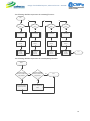
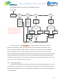
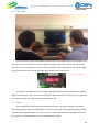
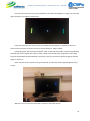
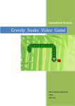
Design of Embedded System, Advanced Course – EDA385 PONG Final Report October, 26th 2012 Fernando de Andrade Pereira [email protected] [email protected] If there are logos here, there should be logos of Lund University rather than something else… Design of Embedded System, Advanced Course – EDA385 Abstract Pong is one of most classic games from the video game era. Since its introduction, in 1972, until the present day, it has received several new versions with different features, gameplays and graphics, in many kinds of platforms. The FPGAs lets us to develop joint solutions of hardware and software, and, although the resources are limited, the optimization can be raised to higher levels. In this project, this higher integration was one of the main factors that led to a working solution in many cases. The system developed has a simple hardware architecture, based in the Xilinx™ MicroBlaze processor and some peripherals, including a VGA controller, and the software architecture is based in the partition of the routines that implement the game logic and the routines that do the communication between the processor and the peripherals. Lots of problems occurred during the development and, with this, that much knowledge has been acquired. 1 Design of Embedded System, Advanced Course – EDA385 Contents 1 Introduction ......................................................................................................................... 4 1.1 History ............................................................................................................................. 4 1.2 The Embedded System Pong ........................................................................................... 4 2 Specifications ....................................................................................................................... 5 2.1 Initial Propose .................................................................................................................. 5 2.2 Modifications ................................................................................................................... 5 2.3 Equipment needed .......................................................................................................... 5 3 Implementation ................................................................................................................... 6 3.1 Hardware ......................................................................................................................... 6 3.1.1 Architecture ............................................................................................................. 6 3.1.2 VGA Controller......................................................................................................... 6 3.2 Software .......................................................................................................................... 8 3.2.1 Software structure................................................................................................... 8 3.2.2 Game Logic ............................................................................................................ 10 3.2.3 Interrupt Routines ................................................................................................. 13 3.2.4 Keyboard Polling .................................................................................................... 14 3.2.5 The Computer Controlled Pad ............................................................................... 14 4 Problems and Solutions ..................................................................................................... 14 5 Final Result ........................................................................................................................ 15 5.1 FPGA Usage ................................................................................................................... 15 5.2 The game ....................................................................................................................... 19 5.3 Tests............................................................................................................................... 19 6 User Manual ...................................................................................................................... 20 6.1 Preparations .................................................................................................................. 20 6.2 Playing ........................................................................................................................... 20 7 Possible Extensions............................................................................................................ 22 8 Conclusion and Lessons Learned ....................................................................................... 22 2 Design of Embedded System, Advanced Course – EDA385 9 Contributions and Thanks ................................................................................................. 23 10 Bibliography and References ............................................................................................. 23 3 Design of Embedded System, Advanced Course – EDA385 1 Introduction 1.1 History The game Pong was first developed by Atari Inc. in 1972, and was one of the first arcade games to reach mainstream popularity. It was the first video game to be considered a sports simulator, inspired in the table tennis. The first implementation of the game used only TTL technology with discrete components. No processor, memory or software was used. Nevertheless, the miniaturization of the system and the introduction of new features in the game led to the utilization of most advanced technologies as microprocessors, RAM, ROM and implementation of the logic in software. The game was ported to several other platforms and received a lot of new features, like modifications in the gameplay and better graphics. 1.2 The Embedded System Pong The goal of this project was develop a complete system (hardware and software) as a platform where one or two players can play Pong. This system was implemented to run in a Nexys™ 3 board with a Spartan-6 FPGA. The hardware architecture is based on a Xilinx™ MicroBlaze processor with BRAM and some peripherals, as a VGA controller, a timer, a PS/2 controller and a seven segments display controller. The source was coded in VHDL. The software was coded in C and compiled to MicroBlaze instructions. Beyond the game logic, some high level functions for the communication between the processor and the peripherals were also implemented in software. Although this increases the RAM usage, it facilitates the codification. There are some differences between this implementation’s gameplay and another Pong’s implementations. The major difference is in the way that the direction and the speed of the ball is calculated after it hits a pad. In the original implementation, by example, the speed and the direction of the ball had depended of the position in pad that the ball hits. In this implementation, it depends also of the previous direction and speed of the ball. Throughout the project development, some modifications in the specifications of the system had been done, because of short time and better solutions thought a posteriori. A lot of problems occurred because of poor documentations of built-in components. 4 Design of Embedded System, Advanced Course – EDA385 2 Specifications 2.1 Initial Propose Initial Proposal At the first moment, the goals of the project were determined as: Output graphics to a VGA monitor in a resolution of 640x480 @ 60Hz; Score of the players showed in the seven segments display; Input controls captured from an USB keyboard; Game for 2 players or 1 player (computer use artificial intelligence to control the pad); Rendering via software; Objects (pads and ball) with rounded edges; Different levels of difficulty. 2.2 Modifications While the project had been developed, some modifications were done in the propose (because these modifications are a better design options or there was no time for the implementation, due to my group mate has dropped out): Rendering via hardware (done by the VGA controller, the same component responsible for the VGA output). It reduces the usage of RAM and cycles of the MicroBlaze; Input controls captured from a USB keyboard, but with a PS/2 controller; Use of a pseudo-A.I. to the computer controlled pad in the 1 player match; Objects with rectangular edges, instead of rounded ones (simplification); No different levels of difficulty (simplification). 2.3 Equipment needed Nexys™ 3 Spartan-6 FPGA Board; VGA monitor; USB Keyboard (The system works well with Swedish and Brazilian – ABNT2 – standards. Other kinds of keyboard standards weren’t tested, but it must work with most of the QWERTY standards). 5 Design of Embedded System, Advanced Course – EDA385 3 Implementation 3.1 Hardware 3.1.1 Architecture The architecture of the system is based on the Xilinx™ MicroBlaze processor. This picture is not very accurate, since the PLB/AXI bus is not shown. You should have the interfaces between these components specified in more detail... Your english is generally rather good, so my comments here are intended only to improve it further: ...except the VGA controller, and do not need a special (detailed) description. All the components are built-in components from Xilinx™ or Digilent™ libraries, unless the VGA controller, and don’t need especial description. The MicroBlaze is a single core processor with 50MHz clock, without floating point unit. The BRAM size utilized is 32Kbytes. 3.1.2 VGA Controller The VGA controller is both the unit responsible by the rendering and the generation of the of VGA signals. It has 7 registers accessible by software in slave mode: reg_slv0 (ball radius); reg_slv1 (pad1 radius); reg_slv2 (pad2 radius – and the information about the color of this pad); reg_slv3 (ball position in the x axis); reg_slv4 (ball position in the y axis); reg_slv5 (pad1 position in the y axis); reg_slv6 (pad2 position in the y axis). The registers are all 32 bits, but only 10 bits are used in each register, unless in the reg_slv2, that use the 11bits, the 11th bit contains the information about the color of the pad, that can be blue 6 Design of Embedded System, Advanced Course – EDA385 (PvP game mode) or green (PvC game mode). 10 bits are enough to represent values between 0 and 639, the range of possible values to represent the position in x axis. This values are present in the bits 22 to 31 of the registers where the bit 22 is the most significant bit (in the reg_slv2, the bit 21 contains the information about the color). While the VGA output generate the 8 bits color output, it verifies if that bit is a wall, ball or one of the pads, generating a bit of the respective color, or a black bit otherwise. The following code illustrates the rendering: ------------------------------------------------------------------------------------------------------------------if(((horizontal_counter - (slv_reg0(23 to 31) & '0')) < "0010010000") and ((vertical_counter - "0000100111") < (slv_reg5(22 to 31) + slv_reg1(22 to 31))) and ((vertical_counter - "0000100111") >= (slv_reg5(22 to 31) - slv_reg1(22 to 31)))) then R0 <= '1'; R1 <= '1'; R2 <= '1'; If you wanted to display the behavior, a diagram would have been better. If you do want to display code, you should compact it a little bit. G0 <= '1'; G1 <= '1'; G2 <= '1'; B1 <= '0'; B2 <= '0'; -elsif (((horizontal_counter + (slv_reg0(23 to 31) & '0')) >= "1100010000") and ((vertical_counter - "0000100111") < (slv_reg6(22 to 31) + slv_reg2(22 to 31))) and ((vertical_counter - "0000100111") >= (slv_reg6(22 to 31) - slv_reg2(22 to 31)))) then R0 <= '0'; R1 <= '0'; R2 <= '0'; G0 <= '0'; G1 <= '0'; G2 <= slv_reg2(21); B1 <= '1'; B2 <= not slv_reg2(21); -elsif(((horizontal_counter - slv_reg3(22 to 31) - slv_reg0(22 to 31)) < "0010010000") and((horizontal_counter - slv_reg3(22 to 31) + slv_reg0(22 to 31)) >= "0010010000") and ((vertical_counter - slv_reg4(22 to 31) - slv_reg0(22 to 31)) < "0000100111") and ((vertical_counter - slv_reg4(22 to 31) + slv_reg0(22 to 31)) >= "0000100111")) then R0 <= '1'; R1 <= '1'; R2 <= '1'; G0 <= '1'; G1 <= '1'; G2 <= '1'; 7 Design of Embedded System, Advanced Course – EDA385 B1 <= '1'; B2 <= '1'; -elsif(((vertical_counter - slv_reg0(22 to 31)) < "0000100111") or ((vertical_counter + slv_reg0(22 to 31)) >= "1000000111")) then R0 <= '1'; R1 <= '1'; R2 <= '0'; G0 <= '0'; G1 <= '0'; G2 <= '0'; B1 <= '0'; B2 <= '0'; -else R0 <= '0'; R1 <= '0'; R2 <= '0'; G0 <= '0'; G1 <= '0'; G2 <= '0'; B1 <= '0'; B2 <= '0'; end if; ------------------------------------------------------------------------------------------------------------------The values "0000100111" (39) - "1000000111" (519) represents the vertical_counter range where the bits are rendered and the values "0010010000" (144) - "1100010000" (784) the horizontal_counter range. These values are chosen because of the generation of the signals Vertical Sync and Horizontal Sync, because of the VGA standards times with 25MHz (the input clock is the same as the processor – 50MHZ – but there’s one process in the VGA controller that reduces the clock by the half) 3.2 Software 3.2.1 Software structure The software was partitioned in 7 source code and 7 headers. ‘main.c’ that call the routine of initialization of the peripherals and the function match() from ‘metagame.c’; ‘metagame.c’ contains the logic of the game. Calculate the ball and pads position in each step and communicate with the peripherals calling the high level drivers’ routines; 8 Design of Embedded System, Advanced Course – EDA385 ‘keyboard_driver.c’ is the driver responsible by initialize the PS/2 driver and capture the keys in the polled mode, sending the information to the game about the state of the pads (moving up, down or stopped) , if ESC key was pressed (pausing/ resuming the game), and if at the beginning if left or right arrow are pressed, changing the game mode, or ENTER, to start the game; ‘led_driver.c’ is the drver responsible by initialize the GPIO in the ports where there’re leds and turn on/off leds; ‘ssd_driver.c’ is the driver responsible to send information to the seven segment display controller about the values in that have to be showed (scores); ‘timer_driver.c’ is the driver responsible by initialize the timer and also contains the handler routine to threat the timer interruption (increment counters of ‘metagame.c’); ‘vga_driver.c’ is the driver responsible by write in the slave registers of the VGA controller the respective values. 9 Design of Embedded System, Advanced Course – EDA385 3.2.2 Game Logic The most important routines in the game logic are represented in dataflows, all this functions are contained in the file ‘metagame.c’. The following dataflow represents the match() function, that contains the logic of one match: Start Good, instructive diagram! Write the initial values in the variables Poll the keyboard No End Game started? Poll the keyboard No Yes Yes Game paused? Poll the Keyboard Game paused? Yes Poll the keyboard No Someone win? nextStep() Yes Turn off the loser pad 10 Design of Embedded System, Advanced Course – EDA385 The following dataflow represents the nextStep() function: Start No No No Pad1 counter >= limit? Pad2 counter >= limit? Ball x counter >= limit? Ball y counter >= limit? Yes Yes Yes Yes nextStepPad1() nextStepPad2() nextStepBallX() nextStepBallY() Restart Pad1 counter Restart Pad2 counter Restart ball x counter Restart ball y counter Send information to the VGA controller Send information to the VGA controller Send information to the VGA controller Send information to the VGA controller End The following dataflow represents the nextStepPad1() function: Start Pad moving UP and don’t reach the max position No Pad moving DOWN and don’t reach the min position Yes Yes Increments position of pad 1 by STEP Decrements position of pad 1 by STEP No End 11 Design of Embedded System, Advanced Course – EDA385 The following dataflow represents the nextStepPad2() function: Start Gamemode is PvP Yes Pad moving UP and don’t reach the max position No Centre of the pad is below the predicted position of the ball Yes Increments position of pad 1 by STEP No Pad moving DOWN and don’t reach the min position Yes Yes Increments position of pad 1 by STEP Decrements position of pad 1 by STEP No End No Centre of the pad is above the predicted position of the ball No Yes Decrements position of pad 1 by STEP The following dataflow represents the nextStepBallY() function: Start Move ball in the y axis by STEP, in the current direction of the ball Ball hits a wall? No End Yes Invert the ball direction in y axis 12 Design of Embedded System, Advanced Course – EDA385 The following dataflow represents the nextStepBallX() function: Start Move ball in the x axis by STEP, in the current direction of the ball Ball cross the player1 goal line? No Ball cross the player2 goal line? Yes Yes Invert the ball direction in x ans y axis; Put the ball in the initial position; Return the speed of the ball to the initial position; Increments player 2 score Invert the ball direction in x ans y axis; Put the ball in the initial position; Return the speed of the ball to the initial position; Increments player 1 score All these diagrams are very good, but some are rather simple. You should focus on the complex behaviors rather than the simple ones. Ball hits the pad1? No Ball hits the pad2? No Yes Yes Invert the ball direction in y axis; Calculate the new speed of the ball in both axis Invert the ball direction in y axis; Calculate the new speed of the ball in both axis Ball hits the pad above the pad’s centre? Ball hits the pad above the pad’s centre? Yes No Yes No New ball direction in y axis is positive New ball direction in y axis is negative New ball direction in y axis is positive New ball direction in y axis is negative Calculate the exact position where the ball will hit the pad2 Yes and introduce a random error Game mode is PvC? Ball position prediction in y axis is the initial position of the ball in y No End interrupt Every time there’s a timer interruption, four variables (ball_y_counter, ball_x_counter, pad1_counter and pad2_counter) are incremented. There are other four values (ball_x_time, ball_y_time, PAD1_TIME0 and PAD2_TIME0) that represent the limit of each counter. When the counter reaches the limit, occurs the respective moving. So, these limits are the inverse of the respective speeds. When the ball hits a pad, the values of ball_x_time and ball_y_time are decreased, and the acceleration may be greater in one of the axis, depending of the distance between where the ball hit the pad and the center of the pad. If this distance is huge, the ball accelerates more in the y axis, if it is small, it accelerates more in the x axis. 3.2.3 Interrupt Routines The software was designed to treat only one interrupt, the timer interrupt. When it occurs, the counters (ball_y_counter, ball_x_counter, pad1_counter and pad2_counter) are incremented by one. The interrupt is programed to occur in every 0.0001s, with a 50MHz clock. The timer is programed in auto-reload mode. 13 Design of Embedded System, Advanced Course – EDA385 3.2.4 Keyboard Polling The inputs from keyboard are captured using the polled mode. This mode was chosen instead of the interrupt mode due to the difficult to make the game response to the keyboard works correctly. Every time the keyboard is polled (as showed in the match() function), the keyboard driver compares the scan code read (if there’s one) with the following values: Stop (0xF0): read the next value, if it is a W (0x1D) or S (0x1B) stop the first pad, otherwise if it is a Up Arrow (0x75) or a Down Arrow (0x72) stop the second pad; 3.2.5 Up Arrow (0x75): moves the second pad up; Down Arrow (0x72): moves the second pad down; W (0x1D): moves the first pad up; S (0x1B): moves the first pad down; Enter (0x5A): if the game is not started yet, start the game; Right Arrow (0x74): if the game is not started yet, change the game to PvC; Left Arrow (0x6B): if the game is not started yet, change the game to PvP; ESC (0x76): pause/resume the game. The Computer Controlled Pad The computer controlled pad use a policy of moving based in the prediction of which will be the ball position in y axis when it return to hit the second pad. When the ball hits the computer controlled pad, the prediction becomes the initial position of the ball in y axis (the center), so the pad moves to the center. When the ball hits the first pad position it calculates, from the current ball position and speeds and using similarity of triangles the exact point where the ball will return, then it introduces a random error (based in the ball_y_counter, that is independent from the ball_x_counter) to this position and the pad moves to this position. This calculation occurs in the function ballNextStepX(). 4 Problems and Solutions The poorly documented usage of the built-in peripherals, especially the Seven Segments Display Controller. The solution was try to write values in different addresses of this peripheral, using pointers in C, and see if the result is the expected; The slave registers of the VGA are written in a nontrivial way, and this kind of communication is poorly documented. The solution was write some values in this 14 Design of Embedded System, Advanced Course – EDA385 registers and try to retrieve, someway, the information. So it was discovered that the 10 bits written in the registers are the bits 22 to 31; Discover the order that the keyboard sends the bytes of the scan codes to the PS/2 controller in polled mode. The solution was press the button and show the hexadecimal scan codes in the seven segment display; Find a good probability factor to the error of the computer controlled pad, because it cannot be so easy or so hard to score goals in the computer controlled pad. The solution was to try a lot of values and play against the computer, until found a balanced amount of goals for both players. 5 Final Result 5.1 FPGA Usage XPS Synthesis Summary (estimated values) Flip Flops Used [-] LUTs Used BRAMS Errors Used Report Generated system on 17. okt 21:32:12 2012 4638 5509 system_vga_ctrl_0_wrapper on 17. okt 21:31:50 2012 393 631 system_clock_generator_0_wrapper on 17. okt 21:31:40 2012 system_mb_plb_wrapper fr 12. okt 06:46:48 2012 161 427 0 system_xps_intc_0_wrapper to 11. okt 23:22:48 2012 120 85 0 system_proc_sys_reset_0_wrapper to 11. okt 23:22:40 2012 69 55 0 system_mdm_0_wrapper to 11. okt 23:22:34 2012 123 126 0 system_xps_timer_0_wrapper to 11. okt 23:22:22 2012 293 272 0 system_mem_bus_mux_0_wrapper to 11. okt 57 0 17 0 0 0 15 Design of Embedded System, Advanced Course – EDA385 23:22:12 2012 to 11. okt 23:22:06 2012 320 484 to 11. okt system_digilent_quadspi_cntlr_wrapper 23:21:58 2012 556 723 to 11. okt system_ps2_mouse_keyboard_wrapper 23:21:42 2012 553 758 0 system_push_buttons_4bits_wrapper to 11. okt 23:21:30 2012 98 52 0 system_leds_8bits_wrapper to 11. okt 23:21:22 2012 126 64 0 system_rs232_uart_1_wrapper to 11. okt 23:21:14 2012 149 153 0 system_lmb_bram_wrapper to 11. okt 23:21:00 2012 system_ilmb_cntlr_wrapper to 11. okt 23:20:54 2012 2 6 0 system_dlmb_cntlr_wrapper to 11. okt 23:20:48 2012 2 6 0 system_dlmb_wrapper to 11. okt 23:20:42 2012 1 0 system_ilmb_wrapper to 11. okt 23:20:36 2012 1 0 system_microblaze_0_wrapper to 11. okt 23:20:16 2012 1671 system_digilent_sevseg_disp_wrapper 0 1 16 1610 [-] Slice Logic Utilization Used Available Utilization Note(s) Number of Slice Registers 3,688 Number used as Flip Flops 0 0 Device Utilization Summary (actual values) 18,224 0 20% 3,681 Number used as Latches 0 Number used as Latch-thrus 0 16 Design of Embedded System, Advanced Course – EDA385 Number used as AND/OR logics Number of Slice LUTs Number used as logic 7 4,364 9,112 47% 4,077 9,112 44% 2,176 6% Number using O6 output only 2,893 Number using O5 output only 245 Number using O5 and O6 939 Number used as ROM 0 Number used as Memory 150 Number used as Dual Port RAM 64 Number using O6 output only 0 Number using O5 output only 0 Number using O5 and O6 Number used as Single Port RAM Number used as Shift Register 64 0 86 Number using O6 output only 27 Number using O5 output only 1 Number using O5 and O6 58 Number used exclusively as route-thrus 137 Number with same-slice register load 114 Number with same-slice carry load Number with other load 23 0 Number of occupied Slices 1,649 2,278 72% Nummber of MUXCYs used 1,052 4,556 23% Number of LUT Flip Flop pairs used 5,025 Number with an unused Flip Flop 1,857 5,025 36% 661 5,025 13% 2,507 5,025 49% Number with an unused LUT Number of fully used LUT-FF pairs Number of unique control sets 236 Number of slice register sites lost to control set restrictions 871 18,224 4% 81 232 34% Number of LOCed IOBs 81 81 100% IOB Flip Flops 28 Number of bonded IOBs Number of RAMB16BWERs 16 32 50% Number of RAMB8BWERs 2 64 3% Number of BUFIO2/BUFIO2_2CLKs 1 32 3% Number used as BUFIO2s 1 17 Design of Embedded System, Advanced Course – EDA385 Number used as BUFIO2_2CLKs 0 Number of BUFIO2FB/BUFIO2FB_2CLKs 0 32 0% Number of BUFG/BUFGMUXs 3 16 18% Number used as BUFGs 3 Number used as BUFGMUX 0 Number of DCM/DCM_CLKGENs 0 4 0% Number of ILOGIC2/ISERDES2s 5 248 2% 0 248 0% 21 248 8% Number used as ILOGIC2s 5 Number used as ISERDES2s 0 Number of IODELAY2/IODRP2/IODRP2_MCBs Number of OLOGIC2/OSERDES2s Number used as OLOGIC2s Number used as OSERDES2s 21 0 Number of BSCANs 1 4 25% Number of BUFHs 0 128 0% Number of BUFPLLs 0 8 0% Number of BUFPLL_MCBs 0 4 0% Number of DSP48A1s 3 32 9% Number of ICAPs 0 1 0% Number of MCBs 0 2 0% Number of PCILOGICSEs 0 2 0% Number of PLL_ADVs 1 2 50% Number of PMVs 0 1 0% Number of STARTUPs 0 1 0% Number of SUSPEND_SYNCs 0 1 0% Average Fanout of Non-Clock Nets 3.88 These full tables are not really very interesting. You could have compiled the data a bit and show only the relevant measures. 18 Design of Embedded System, Advanced Course – EDA385 5.2 The game The final result is a game controlled by keyboard that can be played by one or two players. The score of the match is showed in the seven segment display present on the board. The match starts with zero points to both players and ends when some player scores twelve points. The two left digits show the left player score and the two right digits show the right player score. Nice with photos! The graphics of the game are really simple, with objects (pads, walls and ball) with rectangular edges. The left player’s pad is yellow, the right player’s pad is blue if it is a human player, or green if it is a computer player. The ball is white and the walls are red. 5.3 Tests The final game was tested with several matches between real players that give a feedback about the gameplay. Most of the feedbacks were positive, but some user complained about the bad response of the keyboard when 3 or more keys are pressed in the same time. The players found the game quite fun, especially because of the acceleration of the ball. 19 Design of Embedded System, Advanced Course – EDA385 6 User Manual The instructions for the use of the system are very simple. 6.1 Preparations After the programming of the FPGA, the user has to plug the VGA port of the Nexys™ 3 board in a VGA monitor and plug a USB keyboard in the USB port of the board. 6.2 Playing When the system is turned on, the first view is this: 20 Design of Embedded System, Advanced Course – EDA385 One can press the Enter key on the keyboard to start the match (Player vs. Player), or press the right arrow key to change the view to this: If the user presses Enter in this screen, the match will start (Player vs. Computer). One can press the left arrow key to return to the first screen (Player vs. Player mode). During the game, the first player (left pad – both in PvP and PvC modes) controls the pad using the W key to move it up and the S key to move it down. The second player (right pad in PvP mode) controls the pad with the Up and Down arrows keys. One can press ESC to pause the game, and ESC again to resume it. After a player scores 12 points, the game will end, and only the winner pad will appear in the screen: When this occurs, one must press ESC to return to the initial screen. 21 Design of Embedded System, Advanced Course – EDA385 Summarizing: As a general rule: when copying pictures or any other material from other documents or websites, you need to give a reference to it! 7 Possible Extensions Some features can be introduced in the system in the future: Different levels of difficulty (not introduced yet); Objects with rounded edges (not introduced yet); More balls (some small modifications in the rendering hardware component are needed); A menu to the game (huge modifications in the rendering hardware component are needed); A better (more realistic) A.I. for the computer controlled pad; Create a DMA to the communication (instead of slave registers) with the rendering hardware component, making the system more flexible; Usage of interrupt instead of polled mode to the capture of signals from the keyboard. 8 Conclusion and Lessons Learned One of the most important lessons of this project was that a good documentation is as important as a good implementation in most of cases. With there’s no good documentation, people will lost a lot of time to find how to integrate the components in their systems. Another important lesson is that a good partition of the code (both VHDL and C) can increase the processor and RAM usage, and also the code, but reduces the debugging time. The simplest solution is most of times better than a generic one (that can solve a lot of problem, not just the specified one) in the embedded systems design, because of the limitations in the RAM size and processor speed. It can reduce the flexibility of the system to future changes, but it is a design pattern on systems with limited resources. 22 Design of Embedded System, Advanced Course – EDA385 9 Contributions and Thanks Most of the system was developed by Fernando de Andrade Pereira (the project’s owner). Some drivers as ‘keyboard_driver.c’, ‘led_driver.c’, ‘timer_driver.c’ and the respective headers were partially copied from examples from the Xilinx™ library. This project was developed with support by CNPq – Conselho Nacional de Desenvolvimento Científico e Tecnológico –, of the Ministry for Science and Technology of Brazil. 10 Bibliography and References Pong history: http://www.pong-story.com/atpong1.htm Digilent board Nexys 3 user manual, schematics and examples of use: http://www.digilentinc.com/Data/Products/NEXYS3/Nexys3_rm.pdf http://www.digilentinc.com/Data/Products/NEXYS3/NEXYS3_sch.pdf http://www.digilentinc.com/Data/Products/NEXYS3/Nexys3_EDK_GPIO_UART.zip VGA specifications and timing: http://martin.hinner.info/vga/timing.html http://www.osdever.net/FreeVGA/vga/vga.htm Keyboard scan codes: http://www.ee.bgu.ac.il/~microlab/MicroLab/Labs/ScanCodes.htm A very good result, considering you worked alone and you have not used these tools before. Well done! 23