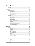
1
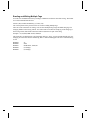
Communications
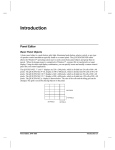
Introduction
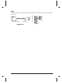
The communications manual is part of the documentation set for QUICKDESIGNER software.
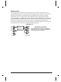
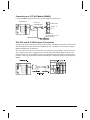
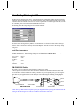
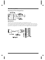
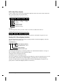
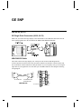
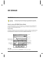
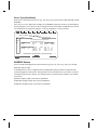
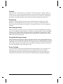
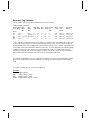
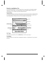
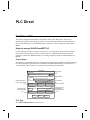
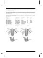
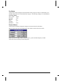
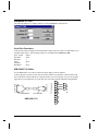
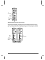
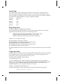
The process of designing panels, loading the panels into a display device and connecting the display to
a PLC is simple. The following diagram shows the basic steps.
Create a NEW project
SETUP the communication options
Design the PANELS
Setup ALARMS
DOWNLOAD the project to a display
Connect the display to your PLC
The first step is to create a new project by selecting a project name then selecting the display device.
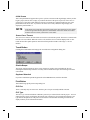
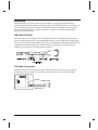
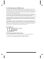
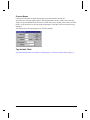
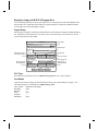
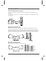
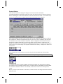
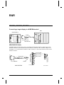
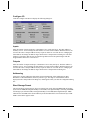
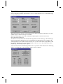
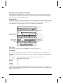
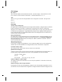
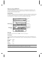
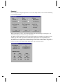
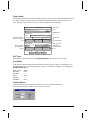
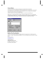
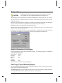
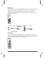
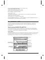
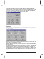
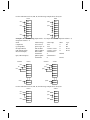
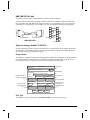
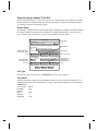
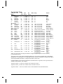
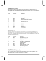
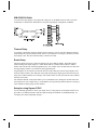
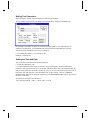
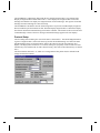
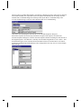
The next step is to select the communications options for your type of PLC. The diagram illustrates the
Project Setup dialog box.
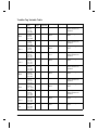
Project Setup
Project name:
More
Project name appears in this field
Disable Beeper
Display Device
Model description appears in this field
Model
Default Panel Name
Screen Saver Timeout
Initial Screen
Display
Print
Touch
PLC & Protocols
Electrical Format
Serial Parameters
PLC Type
CN1
Port
PLC Protocol name appears here
Protocol
OK
Cancel
PLC Protocol setup
Panel Trigger Tag
Watchdog Tag
Watchdog timeout
System
Help
Many of the selections are options and are not necessary for a basic configuration. Most of the
selections have default settings, which are typical settings for most projects. All of the Project Setup
selections are outlined in the following sections.
Communications, GFK-1856
Communications • 1
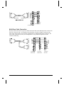
Once the setup is complete, the panels for the project are created. The panels contain the push buttons,
pilot lights, and other panel objects. When the panels are completed, they are downloaded into the
target display, along with the driver for your PLC type. The PLC is then connected to the display and
the project is complete.
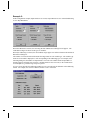
Communication Protocols
There are several steps required to set up communications between the target display and a PLC. The
target display must be loaded with a driver that is specific to your PLC. The display must also be
loaded with information about how the PLC is configured for serial data transmission with the target
display. This section will give you an overview of the required steps.
NOTE
This manual documents the PLC protocols that are supported by the QuickDesigner
and QuickPanel products. PLC model types that are used in this manual are listed as
examples only and not necessarily a limitation on the PLC types that are supported by
the software.
If a particular PLC model is not listed or detailed in this manual, please consult your
PLC vendor or Total Control Technical Support to verify if a listed QuickDesigner
protocol can be used.
Display Device Setup
The target display must have a PLC protocol downloaded to it so it knows what kind of PLC it is
talking to. The PLC protocol file that is downloaded is called an executable file. QUICKDESIGNER
software has a download routine called QUICKCOURIER that is used to make the connection to the
target display and handle the download operation. To start QUICKCOURIER, you click the Download
button.
Target Display Condition
Beginning with version 1.06 software, QUICKCOURIER has the ability to read the display device
status and determine which protocol, if any, has been loaded. Once QUICKCOURIER reads the status,
it can automatically download a new application, including a new display device executable file if
necessary.
NOTE
If you are upgrading to a new version software, you must download a new display
device executable file. A test for the latest version is done automatically when you
download a new project.
New factory units do not have a display device driver installed. When you apply power to a new unit, it
will display a message indicating it is ready to receive a display device executable file.
2 • Communications
Communications, GFK-1856
QUICKDESIGNER Software
The QUICKDESIGNER software running in your computer is used to configure a target display for
operation with your PLC. The configuration information includes the name of the panel that appears
after a power cycle, screen saver timeout, the serial port parameters, and other option settings. Without
the proper configuration information, the target display will not communicate with your PLC.
The QUICKDESIGNER software is also used to design panels that will be displayed on the target
display. Panels contain operators such as push buttons, pilot lights and bar graphs. The download
operation is used to send panel designs and configuration information to a target display.
For each PLC there is a unique protocol driver. You must have the correct protocol driver loaded into
the target display in order to communicate with your PLC. The protocol file is called a display device
executable file. The condition of your target display will determine if the download operation will
include sending the display device executable file.
Creating a New Project
The following sections illustrate all the dialog boxes and option selections necessary for a project.
Remember that some of the selections are optional and are not necessary for a basic project. A good tip
is to start with a simple project, then add the options after you have tested the simple project and are
satisfied it is working properly.
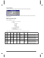
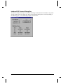
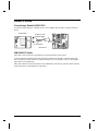
New Project Dialog Box
Enter the New Project name in the New Project dialog box. The project name will allow you to easily
identify it later. Select a target display device and click the OK button when done.
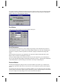
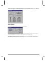
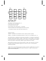
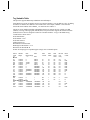
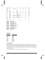
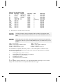
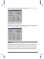
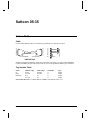
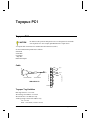
The product label contains the model number and serial number. Below is a sample list of models.
Communications, GFK-1856
Communications • 3
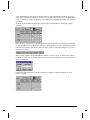
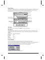
Project Setup Dialog Box
The Project Setup dialog box can be displayed by clicking the Setup button. It will automatically
appear when you start a new project and click the OK button. The dialog box is divided into three
major sections.
Project Name
The Project name section displays the project name in a text field at the top of the dialog box. If you
click the More button, the Additional Project Setup dialog box will appear. This additional section is
used to keep project notes and the project author.
Model
The Display Device Model list box will indicate which display model you selected for the current
project. You can change the display model by clicking the down arrow next to the Model text field and
selecting a new model from the drop down list.
Initial Screen List Box
This is the panel that will appear after a power cycle has occurred on the target display. See Initial
Screen on page 5.
Display Button
Clicking the display button will bring up the Display Configuration dialog box.
4 • Communications
Communications, GFK-1856
Initial Screen
This is the panel that will appear after a power cycle has occurred on the target display. When you first
begin a project, this list box is empty. If you know the name of the power-up screen, enter it now. A
good tip is to come back to this dialog box after all your panels are completed and select one of the
panel names from the list box. If you leave the Initial Screen entry blank, the target display will
display the panel with ID = 1.
NOTE
If the initial screen name does not match a name in the drop-down list box, the display
screen will go black after the panels are downloaded. Choose the initial screen name
from the list box to insure you have the correct name.
Screen Saver Timeout
The screen saver feature will turn off the screen after a selected time period. The timer is restarted each
time the screen is touched. When the screen is off, touch the screen to turn the display back on. The
touch will not affect panel operators. Enter the timeout period in minutes. The range is 1 to 255
minutes.
Touch Button
Clicking the Touch Button will bring up the Touch Screen Configuration dialog box.
Disable Beeper
The beeper sounds each time an active screen operator is touched. You can disable the beep by
checking the Disable Beep checkbox. You may want to disable the beeper when working in an office
environment.
Keyboard Attached
If you have installed an optional keypad such as the HMI-KPN-20x, click the checkbox.
Print Button
This button brings up the printer setup dialog box.
PLC Port
There is currently only one active PLC interface port. The port is usually labeled CN1/SIO.
PLC Type
The PLC Type section will indicate which PLC protocol you selected for the current project. You can
change the PLC type by clicking the down arrow next to the PLC Type text field and selecting a new
type from the drop down list. The protocol selected here will determine the dialog box that will be
displayed when you click the Protocol button.
Communications, GFK-1856
Communications • 5
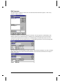
If you select a protocol different from the current protocol shown in the list box, the following prompt
is displayed. The prompt reminds you that the protocol you have just selected must be setup after the
change. Click Yes to acknowledge the prompt.
Port Button
Click the Port button to display the Serial Parameters dialog box.
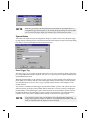
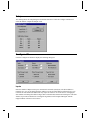
Serial Parameters
The Serial Parameters dialog box is used to change target display serial communication parameters,
such as Baud rate, data bits, etc. Make sure the target display and PLC have the same communication
parameters. A majority of interface problems are related to improper communication settings and
cables.
Select the Electrical Format for your application. The options are RS232, RS422/485 Half or Full
Duplex. This is the format for the display serial port.
Verify the default settings for the serial port are the same as those required by your communication
link. A typical default setting might be 9600 Baud, 8 Data Bits, no parity, 1 Stop Bit and no handshake.
Click the OK button to close the dialog box and return to the Project setup dialog box.
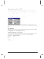
Protocol Button
This button will display the dialog box that is associated with the selected PLC type. Each PLC has
certain setup requirements that must be selected before it will communicate properly with the display
device.
The drawing shows the setup dialog box for Modicon Modbus. You can change the Source ID and the
Timeout. Other protocols have different options. Each PLC type has a dedicated chapter in this manual.
Verify the settings in the setup dialog box are correct and click the OK button.
6 • Communications
Communications, GFK-1856
.
NOTE
Each PLC protocol has a dedicated chapter in this manual. In each chapter there is a
configuration page that will guide you in selecting the proper dialog box entries. Make
sure you select the proper display type and PLC type in the New Project menu.
System Button
This button will display the System Configuration dialog box, which is used to select the panel trigger
tag and setup the watchdog register. The Define Passwords button displays the password settings dialog
box, which is used to establish passwords and password levels.
Panel Trigger Tag
The Panel trigger tag is a register in the PLC that can be used to select a panel for display. Each panel
has a unique ID number which is displayed when you save or open a panel. See Menu commands in the
QUICKDESIGNER section.
When the panel ID number is put in the PLC trigger register, the selected panel will be displayed. The
panel change occurs ONLY when the value in the register changes and the change overrides anything
else being displayed. If you leave Panel trigger tag blank, panel selection is done using the GOTO
PANEL operator.
You can use a combination of Panel trigger tag and GOTO PANEL operators. The operator can select
different panels by pressing a GOTO PANEL button, and the PLC can select a panel by changing the
panel ID number in the Panel trigger register. In this situation, the GOTO PANEL operator will write
the panel ID number to the Panel trigger register to initiate the panel change. The important point to
remember is that a new panel is displayed when a change occurs in the PLC trigger register.
NOTE
If you use Panel Trigger Tag, you should also select a Default Panel. If the Panel
Trigger Tag register in your PLC is equal to 0 or an unused panel ID number, and you
don't use a Default Panel, the display screen will be blank.
Communications, GFK-1856
Communications • 7
Print Trigger Tag
The Printl Trigger tag is a register in the PLC that can be used to print the current screen when the
PLC tag bit goes high. This operation will be invisible to the user. The printer tag is set to zero after a
print is completed.
Watchdog Tag
The Watchdog tag selection is a register in the target PLC that is written to in intervals determined by
the Timeout setting. The target display will write this register in the selected time period. Your PLC
requires additional logic to examine and test the data in order to determine if a communication fault has
occurred.
For example, if the time period is set to 60 (1 min), the display will write (FF) to the designated PLC
register. The PLC logic should first test to see if there is a value in the register. If the register is loaded
with some value, then set it to 0 and wait for a time period longer than the timeout. Check the register
again. If the comm link is good, there should be a value in the register again. If the register is still equal
to 0, then you can assume the comm link has a fault.
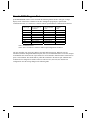
Hardware Reference
This section contains information about the serial interface port and the download port. For additional
hardware reference data, please see the Hardware Reference manual.
Serial Interface Port
The serial interface port connects the QUICKPANEL to your PLC. Factory cables are cut to
approximately 12', which is suitable for most applications. If you need a longer cable, you can order
one from Total Control Products, Inc. or fabricate your own. Cable diagrams can be found in the
Hardware Reference manual and in each PLC chapter. Remember that RS232 cables are reliable up to
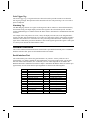
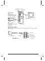
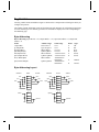
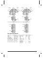
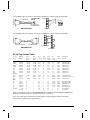
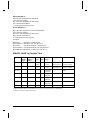
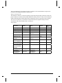
approximately 50'. The serial interface pin assignments are shown in the following table.
PIN
1
2
3
4
5
6
7
8
9
10
11
12
13
8 • Communications
# AME
N
FG Frame Ground
TXD Transmit Data
RXD Receive Data
RTS Request to Send
CTS Clear to Send
Reserved
GND Signal Ground
CD Carrier Detect
TRMX Terminator RXA
RXA Receiving Data +
TXA Sending Data +
No connection
No connection
PIN
14
15
16
17
18
19
20
21
22
23
24
25
# AME
N
Reserved
TXB Sending Data RXB Receiving Data No connection
CTSB Clear to Send DTRB Request to Send DTR Data Terminal Ready
CTSA Clear to Send +
DTRA Request to Send +
Reserved (BUZZGND)
Reserved
Reserved (BUZZOC)
Communications, GFK-1856
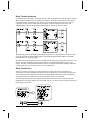
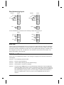
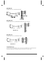
Download Port
The download port, also known as the Tool/CN3 port, has two functions. The primary use is to
download application files from a computer to the target display. The secondary use is to print alarm
messages to a serial printer. The printer option in the configuration menu is used to enable the
download port (Port 1) as a printer port. The download port uses TTL signal levels and requires
conversion to RS232. The HMI-CAB-C49 cable, which is used for downloading files, will convert the
TTL signals to RS232. The HMI-CAB-C105 cable is used to connect a printer to the download port.
Both cables are equipped with a 9-pin D connector that is AT compatible. The download port
connector is an 8-pin mini-DIN style. The port settings are fixed at 9600 Baud, 8 bits, no parity. The
pin assignments for the C49 cable are shown in the following drawing.
HMI-CAB-C49
TXD
RXD
GND
CTS
DSR
+5
1
4
2
6
7
5
TTL
TO
RS232
CONVERTER
590-1000-134/0
8
TO 8-PIN DIN
Communications, GFK-1856
3
2
5
6
8
7
1
TXD
RXD
GND
DSR
CTS
RTS
DCD
PROPRIETARY INFORMATION
THIS INFORMATION IS PROVIDED AS A CONVENIENCE
TO OUR CUSTOMERS. YOU ARE NOT AUTHORIZED TO
CONSTRUCT THIS CABLE. UNAUTHORIZED CABLES ARE
NOT SUPPORTED BY TOTAL CONTROL.
TO PC
9-PIN FEMALE D
Communications • 9
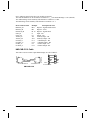
Download
The download process involves connecting your computer to a target display and transferring
communication and panel information to the target display. The download operation is done after you
have selected the PLC protocol, setup the communication options, and designed at least one panel.
Once the download operation is complete, the display is connected to your PLC and the display
becomes the operator interface.
HMI-CAB-C49 Cable
This cable connects your computer to the circular DIN connector on the target display. This cable is
used to download files created by QUICKDESIGNER software in your computer to the target display.
The 9-pin AT connector housing contains an electronic circuit that makes the signals from both devices
compatible. Most cable drawings in this manual include a wiring diagram. Since this cable also
includes custom electronics, no wiring diagram is supplied.
.
C49 Cable Connection
The HMI-CAB-C49 cable is connected to the circular DIN connector port on the target display as
shown below. The 9-pin connector is attached to a serial port on your AT compatible computer.
SIO/CN3
TO SERIAL PORT
HMI -CAB -C49
10 • Communications
Communications, GFK-1856
Allen-Bradley
Allen-Bradley SLC 500
Setup for using an A-B SLC 500
Use the following procedure to ensure your target device is setup properly for the Allen-Bradley SLC
500. The procedure is in condensed format. Only the required settings are outlined. For additional
details, see Creating a New Project beginning on page 3.
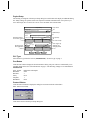
Project Setup
The drawing is a diagram of the Project Setup dialog box. Each button will display an additional dialog
box. Many settings are options and are not required to establish communications. Verify the Project
name and Display Device Model are correct. Leave the Initial Screen name blank.
Project Notes
Project Setup
Project name:
More
Project name appears in this field
Disable Beeper
Display Device
Model description appears in this field
Model
Default Panel Name
Screen Saver Timeout
Print (Inactive)
Initial Screen
Display
Print
Touch
PLC & Protocols
Electrical Format
Serial Parameters
PLC Type
CN1
Port
PLC Protocol name appears here
Protocol
OK
Cancel
PLC Protocol setup
Panel Trigger Tag
Watchdog Tag
Watchdog timeout
System
Help
PLC Type
Select the PLC type from the list box. (AB SLC DH485). See PLC Type on page 5.
Communications, GFK-1856
Allen-Bradley • 11
Port Button
Click the Port button to display the Serial Parameters dialog. The port values are automatically set to
standard default values. See Serial Parameters on page 6. The following settings are recommended for
AB SLC DH485.
Elect. Format
or
Elect. Format
Baud Rate
Data Bits
Parity
Stop Bits
Handshake
RS422 Half Duplex (When using the HMI-CAB-C83 Cable)
RS232 (When using the HMI-CAB-C84 Cable)
19200
8
Even
1
None
Protocol Button
Click the Protocol button to display the dialog box associated with the selected PLC.
The Source ID is the target display address on the DH485 network. The Destination ID is the PLC
address where the target display will get variable data. The Maximum node ID is the highest available
address on the DH485 network. The maximum ID should be set to the lowest possible number. Enter
Timeout in seconds. Click OK to return to the Project Setup dialog box.
Protected Files
Processor files with Owner set cannot be written to by QUICKPANEL
The Set and Clear Owner function allows a terminal to "own" one or more processor files on the
network. Ownership means that as long as the owner is active on the network, other terminals can not
access the on-line functions of the owned processor files. Note that only a programmer can own a node.
In the following example, station 1 is owned by node 0. Notice station node 1 has a max. address 31
followed by a forward slash and then the ownership node. If you see this on the display, a
QUICKPANEL cannot write to that station. You must clear the owner.
0 TCP
1 5/02
2 Term
3
(31)
(31/0)
(31)
Connecting to the SLC 500
A single point connection is simply one target display connected directly to the program port of a single
SLC 500. This connection is made using the HMI-CAB-C83 cable.
12 • Allen-Bradley
Communications, GFK-1856
HMI-CAB-C83 Cable
This cable connects the target display serial port to the Allen-Bradley SLC 500 Programming Port.
25-PIN MALE
TO TCP DEVICE
4
5
18
19
21
22
8-PIN MODULAR PHONE
RJ-45
PROPRIETARY INFORMATION
HMI-CAB-C83/A
7
1
(--) 15
16
(+) 10
11
GND
SHIELD
TO SLC 500
PROGRAM PORT
orange
green RJ-45
shield
blue TOP
white
brown
black
red
THIS INFORMATION IS PROVIDED AS A
CONVENIENCE TO OUR CUSTOMERS.
YOU ARE NOT AUTHORIZED TO
CONSTRUCT THIS CABLE.
UNAUTHORIZED CABLES ARE
NOT SUPPORTED BY TOTAL CONTROL.
SLC 500 Network Connection for Programming Equipment (DH485)
This connection allows two devices to be connected to the PLC. In this case, a programming terminal
can be connected to the PLC using a 1747-PIC Interface Converter connected to the HMI-CAB-C84
cable.
The drawing shows the connections for adding a second device to the network connection.
SLC 500 Fixed I/O Controller
QUICKPANEL jr.
TO SLC 500
PROGRAM PORT
TO TCP DEVICE
HMI-CAB-C84
Communications, GFK-1856
TO: Allen-Bradley 1747-PIC
Interface Converter
Allen-Bradley • 13
HMI-CAB-C84 Cable
This cable connects the target display serial port to the Allen-Bradley SLC 500 Programming Port. The
cable is designed to allow connection to additional devices such as an Allen-Bradley 1747-PIC
Interface Converter.
Warning: The maximum length of this cable is 6 feet. Do not attempt to make it longer.
25-PIN MALE
8-PIN MODULAR PHONE(MALE)
8-PIN MODULAR PHONE(FEMALE)
HMI-CAB-C84/A
25-pin male D
CABLE LENGTH = 6'
RS232
TO
RS422
CIRCUIT
BOARD
orange -8
green -7 (G)
shield -6
blue -5 (E)
white -4
brown -3
black -2 ( - )
red
-1 (+)
CABLE LENGTH = 1'
PROPRIETARY INFORMATION
orange -8
RJ-45
green -7
shield -6 TOP
blue -5
white -4
brown -3 8-PIN MODULAR
black -2 PHONE PLUG
red
-1
8-PIN MODULAR
PHONE JACK
THIS INFORMATION IS PROVIDED AS A CONVENIENCE
TO OUR CUSTOMERS. YOU ARE NOT AUTHORIZED TO
CONSTRUCT THIS CABLE. UNAUTHORIZED CABLES ARE
NOT SUPPORTED BY TOTAL CONTROL.
THE RS232 CONVERTER CIRCUITS ARE CONTAINED ON
A CIRCUIT BOARD WITHIN THE 25-PIN D-SHELL. THE
ELECTRONIC CIRCUIT PROVIDES NETWORK CONTROL.
THE CIRCUIT DIAGRAM IS PROPRIETARY INFORMATION.
THE CABLE IS LICENSED FROM ALLEN-BRADLEY.
SLC 500 Network Connection using 1747 AIC Link Couplers (DH485)
14 • Allen-Bradley
Communications, GFK-1856
Connecting to a 1747 AIC Module (DH485)
Connect the HMI-CAB-C84 cable to the 1747 AIC Module as shown below.
QUICKPANEL jr.
TO SLC 500
PROGRAM PORT
DH485 Interface
Peripheral - J2
CPU -J1
TO TCP DEVICE
1747-AIC MODULE
HMI-CAB-C84
TO: Allen-Bradley 1747-PIC
Interface Converter
SLC 5/03 and SLC 5/04 Channel 0 Connection
The SLC 5/03 and SLC 5/04 processors let you operate DF1 communication protocol by means of the
RS-232 communication port, channel 0. In addition, the SLC 5/03 and SLC 5/04 processors support
DH485 communication via channel 0.
The 9-Pin connector on the SLC 5/03 and SLC 5/04 processors is programmable. The SLC 5/03 and
SLC 5/04 processors can be configured for port-to-port connection using the HMI-CAB-C52 cable.
Channel 0 must be set up as a DH485 master. This configuration can only read/write variables in the
local PLC. Since it is not dependent on network loading, this configuration will provide quick display
updates.
Communications, GFK-1856
Allen-Bradley • 15
HMI-CAB-C52 Cable
This cable is used to connect the target display to a SLC 5/03 and SLC 5/04 RS232 Channel 0 Port.
TO TCP DEVICE
TO PLC PORT
9 PIN FEMALE
25 PIN MALE
A label is placed on each end of the cable to indicate which device should be connected to that end.
One of the labels will also indicate the cable part number so you can quickly verify you are using the
right cable for your application. You can make your own cable using the following wiring diagram.
2
3
4
5
7
1
SHIELD
TO TCP DEVICE
HMI-CAB-C52
2
3
4
6
5
7
8
1
TO PLC PORT
SLC 5/03 and SLC 5/04 DH485 Connections
You can connect channel 0 of the SLC 5/03 and SLC 5/04 modules to the 1747-PIC to make a
connection to the DH485 network.
SLC 500 5/02 Modular Controller
SLC5/04 Modular Controller
SLC 5/04 CPU
RUN
FORCE
FLT
DH+
BATT
RUN
RS23 2
REM
PROG
1747-AIC Link Coupler
1747-PIC
HMI-CAB-C84
1747-PIC
QUICK PANEL Jr.
Programming
Station
Setup for using a SLC 5/03 and SLC 5/04 Channel 0
The procedure for setup of an AB SLC 5/03 Channel 0 is basically the same as for SLC500 DH485.
The Electrical Format must be set to RS232.
16 • Allen-Bradley
Communications, GFK-1856
SLC 5/04 Data Highway Plus
Data Highway Plus implements peer-to-peer communication with a token-passing scheme to rotate link
mastership among a maximum of 64 nodes. Since this method does not require polling, it helps provide
time-efficient reliable data transport.
The SLC 5/04 processor lets you operate DH+ communication protocol by means of the DH+
communication channel 1. The SLC 5/04 also supports full-duplex DF1 protocol using the DF1
channel 0.
The 3-pin connector is for actual DH+ communication and the 8-pin connector is for monitoring DH+
communication.
The DH+ LED provides an indication of the condition of the network communication. The color can be
green or red. A steady on condition indicates the processor is actively communicating on the network.
Flashing green indicates there are no active nodes on the network. Flashing red indicates there are
duplicate nodes on the link with the same node address.
SLC 5/04 CPU
RUN
FORCE
FLT
DH+
BATT
RUN
RS232
REM
PROG
DH+
Channel 1
DF1
Channel 0
SLC 5/04 DH+ Connection
The drawing shows a possible configuration for DH+.
PLC 5/15
QUICKPANEL
SLC5/04 Modular Controller
SLC 5/04 CPU
RUN
FORCE
FLT
DH+
BATT
RUN
RS23 2
REM
PROG
CN1
DATA
HIGHWAY
PLUS
MODULE
LINE 2 BLUE
SHIELD
LINE 1 CLEAR
Communications, GFK-1856
Allen-Bradley • 17
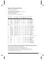
SLC 500 Tag Variables for DH485 Protocol
The following chart lists the legal tag variable names that can be used with the SLC 500 series. The
target display talks to the SLC500 using the DH485 protocol. The DH485 protocol requires each
device to have a node address. The Source ID is the target display node address and the Destination ID
is the node address for the SLC. (See the "Setup for using an AB SLC 500 PLC" section for details
about entering the source and destination ID's).
When there is a single point connection between a target display and a SLC500, the destination ID
(node address for SLC) becomes the default address for all variables. That is, if you use the tag variable
N7:100, the target display knows that this variable is located at the destination node address.
When the target display is connected to a DH485 network that includes multiple SLC nodes, there is an
optional variable naming element that will allow you to read information from any SLC node. The
additional element is _D, where the underscore D indicates a node address other than the Destination
ID node address.
In this example, the Source ID (target display address) has been set to 0 and the Destination ID (SLC
node address) has been set to 1. There is an additional SLC on the DH485 network located at node
address 3. To read information from node address 1, the variable would be N7:100. Remember that the
Destination ID is the default node address. To read information from node address 3, the variable
would be N7:100_3. The general format for tag variables is shown below.
N7:100/00_D
Destination Node Address
Bit Address
Element
File Type
SLC 500 Tag Variables for DH+ Protocol
The DH+ tag variables are the same as the PLC5 tag variables except for the following items.
1. You cannot read or write Input (I) or Output (O) variables in the SLC 5/04.
2. The SLC 5/04 can read/write string variables (ST) while the PLC 5 cannot.
18 • Allen-Bradley
Communications, GFK-1856
Tag Variable Table
File Type
O0:00
OD:00
OO:00
I1:00
ID:00
IO:00
S2:00 or S:
File #
0
0
0
1
1
1
2
B3: or Bn:
T4: or Tn:
n:=9-255
n:=9-255
C5: or Cn:
n:=9-255
R6: or Rn:
n:=9-255
N7: or Nn:
n:=9-255
ND7: or NDn:n:=9-255
NL7: or NLn: n:=9-255
F8: or Fn:
n:=9-255
D9: or Dn:
n:=9-255
A9: or An:
n:=9-255
ST9: or STn:
Element
0-255 (dec)
0-255 (dec)
0-377 (oct)
0-255 (dec)
0-255 (dec)
0-377 (oct)
0-15 5/01(1)
0-32 5/02(1)
0-83 5/03(1)
0-255
0-255.ACC
0-255.PRE
0-255.EN
0-255.TT
0-255.DN
0-255.ACC
0-255.PRE
0-255.DN
0-255.CU
0-255.CD
0-255.OV
0-255.UN
0-255.UA
0-255.LEN
0-255.POS
0-255.DN
0-255.EN
0-255.ER
0-255.UL
0-255.IN
0-255.FD
0-255
0-255
0-255
0-255
0-255
0-255
1-9999
Bit Range
/0 - /15
/0 - /15
/0 - /17
/0 - /15
/0 - /15
/0 - /17
/0 - /15
Write
Y
Y
Y
N
N
N
N
Value
-32768 to 32767
-32768 to 32767
-32768 to 32767
-32768 to 32767
-32768 to 32767
-32768 to 32767
-32768 to 32767
/0 - /15
Y
Y
Y
Y
Y
Y
Y
Y
Y
Y
Y
Y
Y
Y
Y
Y
Y
Y
Y
Y
Y
Y
Y
Y
Y
Y
Y
Y
Y
-32768 to 32767
0-32767
0-32767
0-1
0-1
0-1
-32768 to 32767
-32768 to 32767
0-1
0-1
0-1
0-1
0-1
0-1
-32768 to 32767
-32768 to 32767
0-1
0-1
0-1
0-1
0-1
0-1
-32768 to 32767
-2147M to 4294M
-2147M to 4294M
-2147M to 4294M
0-9999
Null - ASCII
0-65535
/0 - /15
NS
NS
NS
NS
Note 1: File numbers other than the default value shown are 9-255. Ex: B5:0 would be invalid.
Note 2: Address range for I and O are in decimal as maped in the M files.
Note : Address Max for S is dependent on the PLC.
Note: Bits may wrap into other words. Ex: B3:5/41 = B3:7/9
Note: Integer types (range –32768 to 32767) may be configured as unsigned (range 0 to 65535)
Note: Node ID Max. is 254 for the SLC DF1 and 31 for the SLC 485.
Note 6: For NL7:0, N7:0 is the MSB and N7:1 is the LSB. For ND7:0, N7:1 is the MSB and N7:0 is the LSB.
Communications, GFK-1856
Allen-Bradley • 19
Additional Information
Network Performance
The following are major configuration factors that have a significant effect on network performance:
• The number of nodes on the link
• The addresses of those nodes
• The maximum node address selection
The number of nodes on the link directly affects the data transfer time between nodes. Unnecessary
nodes slow the data transfer rate. The maximum number of nodes on the link is 32.
The best link performance occurs when node addresses start at 0 and are assigned in sequential order.
Also, initiators such as personal computers should be assigned the lowest numbered addresses to
minimize the time required to initialize the link. If all nodes are expected to be connected at all times,
this is really all you need to do.
The maximum node address parameter should be set as low as possible. This minimizes the amount of
time used in soliciting successors when initializing the link. If all nodes are addressed in sequence from
0, and the maximum node address is equal to the address of the highest addressed node, the token
rotation will improve by the amount of time required to transmit a solicit successor packet plus the slot
timeout value.
NOTE - The SLC500 processors set the maximum node address to 31 when power is cycled increasing
initialization and response time of the link.
DH-485 Cable
The suggested DH-485 communication cable is BELDEN #9842 cable. The cable is jacketed and
shielded with two twisted wire pair and a drain wire.
DH-485 Connections
One (only one) of the Link Couplers at the end of the link must have Terminals 1 and 2 of the link
connector jumpered together. This provides an Earth Ground connection for the shield of the
communications cable.
Link Couplers at both ends of the link must have Terminals 5 and 6 of the link connectors jumpered
together. This connects the termination impedance that is built into each link coupler as required by the
DH-485 specification.
6 - TERM
5-A
4-B
3 - COMMON
2 - SHIELD
1 - CHS GND
20 • Allen-Bradley
Communications, GFK-1856
Allen-Bradley SLC 500 DF1
CAUTION
Do NOT use this protocol with QP1 devices. It is designed to be used with
ONLY QP2 devices. For example, QPJ-2D100-L2P is a QP2 device.
The SLC 5/03 and SLC 5/04 processors let you operate DF1 communication protocol by means of the
RS-232 communication port, channel 0.
The 9-Pin connector on the SLC 5/03 and SLC 5/04 processors is programmable. The SLC 5/03 and
SLC 5/04 processors can be configured for port-to-port connection using the HMI-CAB-C52 cable.
Channel 0 must be set up for DF1 communication. This configuration can only read/write variables in
the local PLC. Since it is not dependent on network loading, this configuration will provide quick
display updates.
HMI-CAB-C52 Cable
TO TCP DEVICE
TO PLC PORT
9 PIN FEMALE
25 PIN MALE
This cable is used to connect the target display to a SLC 5/03 and SLC 5/04 RS232 Channel 0 Port.
Make sure the port is set to DF1 protocol.
2
3
4
5
7
1
SHIELD
TO TCP DEVICE
HMI-CAB-C52
2
3
4
6
5
7
8
1
TO PLC PORT
Setup for using an A-B SLC 500 DF1
Use the following procedure to ensure your target device is setup properly for the Allen-Bradley SLC
500 DF1. The procedure is in condensed format. Only the required settings are outlined. For additional
details, see Creating a New Project beginning on page 3.
Communications, GFK-1856
Allen-Bradley • 21
Project Setup
The drawing is a diagram of the Project Setup dialog box. Each button will display an additional dialog
box. Many settings are options and are not required to establish communications. Verify the Project
name and Display Device Model are correct. Leave the Initial Screen name blank.
Project Notes
Project Setup
Project name:
More
Project name appears in this field
Disable Beeper
Display Device
Model description appears in this field
Model
Default Panel Name
Screen Saver Timeout
Print (Inactive)
Initial Screen
Display
Print
Touch
PLC & Protocols
Electrical Format
Serial Parameters
PLC Type
CN1
Port
PLC Protocol name appears here
Protocol
OK
Cancel
PLC Protocol setup
Panel Trigger Tag
Watchdog Tag
Watchdog timeout
System
Help
PLC Type
Select the PLC type from the list box. (AB SLC DF1). See PLC Type on page 5.
Serial Port Parameters
Click the Port button to display the Serial Parameters dialog. The port values are automatically set to
standard default values. The following settings are recommended for AB SLC DF1.
Elect. Format
Baud Rate
Data Bits
Parity
Stop Bits
Handshake
22 • Allen-Bradley
RS232
9600
8
None
1
None
Communications, GFK-1856
Protocol Button
Click the Protocol button to display the dialog box associated with the selected PLC.
The Source ID is the target display address. The Destination ID is the PLC address where the target
display will get variable data. Enter Timeout in seconds. Select error checking (CRC or BCC) to match
the PLC. Note the Protocol is currently fixed at Full Duplex. Click OK to return to the Project Setup
dialog box.
The drawing shows the setup dialog box for A-B SLC500 DF1.
Tag Variable Table
The general format for the tag variables is found on page 18. See the tag variable table on page 19.
Communications, GFK-1856
Allen-Bradley • 23
Allen-Bradley MicroLogix 1000
The MicroLogix 1000 has an RS-232-C communication port configurable for DF1 protocol for direct
connection to a programming device or operator interface. In this configuration, the MicroLogix 1000
is identical to the SLC500 DF1 protocol. To connect a QuickPanel to a MicroLogix 1000 PLC, use the
SLC 500 DF1 protocol selection and an HMI-CAB-C106 cable.
The drawing shows the setup dialog box for A-B SLC500 DF1.
The Source ID is the target display address. The Destination ID is the PLC address where the target
display will get variable data. Enter Timeout in seconds. Select error checking (CRC or BCC) to match
the PLC. Note the Protocol is currently fixed at Full Duplex. Click OK to return to the Project Setup
dialog box.
Serial Port Parameters
Click the Port button to display the Serial Parameters dialog. The port values are automatically set to
standard default values. The following settings are recommended for AB SLC DF1.
Elect. Format
Baud Rate
Data Bits 8
Parity
Stop Bits 1
Handshake
RS232
9600
None
None
HMI-CAB-C106 Cable
This cable is used to connect the target display to a MicroLogix 1000.
25 PIN MALE
A label is placed on each end of the cable to indicate which device should be connected to that end.
One of the labels will also indicate the cable part number so you can quickly verify you are using the
right cable for your application. You can make your own cable using the following wiring diagram.
TO TCP DEVICE
TO PLC PORT
HMI-CAB-C106
2
3
7
4
5
TO TCP DEVICE
4
7
2
PIN 6
PIN 4
PIN 7
PIN 8
PIN 3
PIN 5
PIN 1
PIN 2
TO PLC PORT
NOTE: The 8-pin DIN connector requires precise pin alignment before pressing the connector into the
housing on the MicroLogix 1000. This is a TIGHT fit and requires some force.
24 • Allen-Bradley
Communications, GFK-1856
Advanced Interface Converter AIC+
The AIC+ (Advanced Interface Converter, 1761-NET-AIC) provides a simplified, cost effective
solution for connecting RS-232 devices to DH-485 networks. Use the AIC+ for communications
connectivity with the MicroLogix 1000 DH-485 networking series controller. The AIC+ is also a good
choice for providing point-to-point RS-232 isolation.
The AIC+ can replace the 1747-PIC/1747-AIC combination when using channel 0 of an SLC 5/03 or
SLC 5/04 processor to access DH-485 or DF1 master-slave networks.
When connecting a QuickPanel to the AIC+ DH485 Port3, you must use the AB SLC DH485 protocol.
The drawing shows the setup dialog box for A-B SLC DH485
The Source ID is the target display address. The Destination ID is the PLC address where the target
display will get variable data. Enter Timeout in seconds. Click OK to return to the Project Setup dialog
box.
Port 3 Example
This example shows a 3-Node network (not expandable). The QuickPanel is connected to the DH-485
network on the AIC Port 3 using the HMI-CAB-C117 cable.
Serial Port Parameters for Port 3 Setup
Click the Port button to display the Serial Parameters dialog. The port values are automatically set to
standard default values. The following settings are recommended for AB SLC DH485.
Elect. Format
Baud Rate
Data Bits
Parity
Stop Bits
Handshake
RS422/485 Half Duplex
19200
8
Even
1
None
Communications, GFK-1856
Allen-Bradley • 25
MicroLogix
QUICKPANEL
PORT 3 DH485/DF1
MASTER-SLAVE
PORT 2
MINI-DIN 8 RS-232
HMI-CAB-C117
TX
600
AUTO
1200
2400
4800
TX
19200
14400
9600
TX
1761-CBL-AM00
OR
1761-CBL-HM02
AIC+
PWR
PORT 1
DB-9 RS-232, DTE
1747-CP3
OR
1761-CBL-AC00
Port 2 Example
This example shows the AIC module as a point-to-point isolator. Here the QuickPanel is connected
using RS-232 to Port 2 on the AIC module. A MicroLogix 1000 (Series C or Higher) can be connected
to the AIC RS-232 Port 1, or you can connect a SLC 5/03 or SLC 5/04 Channel 0 port to Port 1 on the
AIC module.
Serial Port Parameters for Port 2 Setup
Click the Port button to display the Serial Parameters dialog. The port values are automatically set to
standard default values. The following settings are recommended for AB SLC DH485.
Elect. Format
Baud Rate
Data Bits
Parity
Stop Bits
Handshake
26 • Allen-Bradley
RS232
19200
8
Even
1
None
Communications, GFK-1856
PORT 3 DH485/DF1
MASTER-SLAVE
1761-CBL-PM02
OR
1761-CBL-AP00
FOR MICROLOGIX 1000
(SERIES C OR HIGHER)
PORT 2
MINI-DIN 8 RS-232
QUICKPANEL
TX
600
AUTO
1200
2400
4800
TX
19200
14400
9600
TX
1747-CP3
OR
1761-CBL-AC00
FOR SLC5/03 OR SLC 5/04
CHANNEL 0
AIC+
HMI-CAB-C106
PWR
PORT 1
DB-9 RS-232, DTE
HMI-CAB-C117 Cable
25 PIN MALE
The AIC+ can connect a QuickPanel through the Port 3 DH-485/DF1 Phoenix Plug using the HMICAB-C117 cable.
TO TCP DEVICE
TO AIC+
HMI-CAB-C117
Communications, GFK-1856
4
5
18
19
21
22
11
10
15
16
7
1
TO TCP DEVICE
RED
To Terminal B
BLK
To Terminal A
To Terminal COM
To Terminal SHIELD
GRN
SHL
TO AIC+ PORT 3
Allen-Bradley • 27
Tag Variable Table
File Type
O0:00
OD:00
OO:00
I1:00
ID:00
IO:00
S2:00 or S:
File #
0
0
0
1
1
1
2
B3: or Bn:
T4: or Tn:
n:=9-255
n:=9-255
C5: or Cn:
n:=9-255
R6: or Rn:
n:=9-255
N7: or Nn:
ND7: or NDn:
NL7: or NLn:
F8: or Fn:
D9: or Dn:
A9: or An:
ST9: or STn:
n:=9-255
n:=9-255
n:=9-255
n:=9-255
n:=9-255
n:=9-255
Element
0-255 (dec)
0-255 (dec)
0-377 (oct)
0-255 (dec)
0-255 (dec)
0-377 (oct)
0-15 5/01(1)
0-32 5/02(1)
0-83 5/03(1)
0-255
0-255.ACC
0-255.PRE
0-255.EN
0-255.TT
0-255.DN
0-255.ACC
0-255.PRE
0-255.DN
0-255.CU
0-255.CD
0-255.OV
0-255.UN
0-255.UA
0-255.LEN
0-255.POS
0-255.DN
0-255.EN
0-255.ER
0-255.UL
0-255.IN
0-255.FD
0-255
0-255
0-255
0-255
0-255
0-255
1-9999
Bit Range
/0 - /15
/0 - /15
/0 - /17
/0 - /15
/0 - /15
/0 - /17
/0 - /15
Write
Y
Y
Y
N
N
N
N
Value
-32768 to 32767 (DELETE)
-32768 to 32767 (DELETE)
-32768 to 32767 (DELETE)
-32768 to 32767 (DELETE)
-32768 to 32767 (DELETE)
-32768 to 32767 (DELETE)
-32768 to 32767
/0 - /15
Y
Y
Y
Y
Y
Y
Y
Y
Y
Y
Y
Y
Y
Y
Y
Y
Y
Y
Y
Y
Y
Y
-32768 to 32767
0-32767
0-32767
0-1
0-1
0-1
-32768 to 32767
-32768 to 32767
0-1
0-1
0-1
0-1
0-1
0-1
-32768 to 32767
-32768 to 32767
0-1
0-1
0-1
0-1
0-1
0-1
/0 - /15
Y
Y
Y
Y
Y
Y
Y
-32768 to 32767
-2147M to 4294M
-2147M to 4294M
-2147M to 4294M
0-9999
Null - ASCII
0-65535
NS
NS
NS
NS
Note 1: File numbers other than the default value shown are 9-255. Ex: B5:0 would be invalid. (DELETE)
Note 2: Address range for I and O are in decimal as maped in the M files. (DELETE)
Note 1: Address Max for S is dependent on the PLC.
Note: Bits may wrap into other words. Ex: B3:5/41 = B3:7/9
Note: Integer types (range –32768 to 32767) may be configured as unsigned (range 0 to 65535)
Note: Node ID Max. is 254 for the SLC DF1 and 31 for the SLC 485.
28 • Allen-Bradley
Communications, GFK-1856
Allen-Bradley PLC2
Connecting to a PLC-2 Program Port
HMI-CAB-C90
This cable is used to connect the target display to an Allen-Bradley PLC-2 PLC.
A label is placed on each end of the cable to indicate which device should be connected to that end.
One of the labels will also indicate the cable part number so you can quickly verify you are using the
right cable for your application. You can make your own cable using the following wiring diagram.
Communications, GFK-1856
Allen-Bradley • 29
Setup for using an A-B PLC-2 Program Port
Use the following procedure to ensure your target device is setup properly for the Allen-Bradley PLC2.
The procedure is in condensed format. Only the required settings are outlined. For additional details,
see Creating a New Project beginning on page 3.
Project Setup
The drawing is a diagram of the Project Setup dialog box. Each button will display an additional dialog
box. Each button is described below. Verify the Project name and Display Device Model are correct.
Leave the Initial Screen name blank.
Project Notes
Project Setup
Project name:
More
Project name appears in this field
Disable Beeper
Display Device
Model description appears in this field
Model
Default Panel Name
Screen Saver Timeout
Print (Inactive)
Initial Screen
Display
Print
Touch
PLC & Protocols
Electrical Format
Serial Parameters
PLC Type
CN1
Port
PLC Protocol name appears here
Protocol
OK
Cancel
PLC Protocol setup
Panel Trigger Tag
Watchdog Tag
Watchdog timeout
System
Help
PLC Type
Select the PLC type from the list box. (AB PLC2 Prog. Port). See PLC Type on page 5.
Port Button
Click the Port button to display the Serial Parameters dialog. See Serial Parameters on page 6. The
following settings are recommended for AB PLC2 Prog. Port.
Elect. Format
Baud Rate
Data Bits
Parity
Stop Bits
Handshake
30 • Allen-Bradley
RS422/485 Full Duplex
9600
8
Even
1
None
Communications, GFK-1856
Protocol Button
Click the Protocol button to display the dialog box associated with the selected PLC.
Enter Timeout in seconds. Click OK to return to the Project Setup dialog box.
PLC2 Variable Names
Format
WUBa_d
WUBa/00-07_d
WUBa/10-17_d
WUB200/00-07_d
WUB200/10-17_d
WSDa_d
WUDa_d
WSOa_d
WTCa_d
LSDa_d
LSDFa_d
MSGa_d
LHDa_d
Variable Type
Word Unsigned Binary
Bit Read
Range
0 to 65535
0 to 1
Bit Read/Write (above 200 ONLY)
0 to 1
Word Signed Decimal
Word Unsigned Decimal
Word Signed Octal
Word Timer Counter
Long Signed Decimal
Long Signed Decimal Fixed Point
ASCII Message String
Extended Precision BCD
-999 to 999
0 to 9999
-4095 to 4095
0 to 999
-999999 to 999999
-999.999 to 999.999
0 to 65535
-79999999 to +79999999
In the above table, "a" is a one to five digit octal address that specifies the address in the data table.
The "_d" is the PLC Destination Address on the Data Highway.
WUB - Word Unsigned Binary
A WUB variable type is used to read an unsigned binary word from the PLC data table, which is
converted to a decimal value between 0 and 65535. The WUB variable is used to read input, output and
control relay points. All sixteen I/O or control points are read at one time.
Example:
The following binary value is present in a PLC2/15 at address 250.
17 16 15 14 13 12 11 10 7 6 5
4 3 2
1 0
0 1 0 1 0 1 0 1 0 1 0 1 0 1 0 1
Reading this variable would result in the value 21845 because this is the decimal equivalent of the
binary value shown in the example.
Communications, GFK-1856
Allen-Bradley • 31
The WUB variable type can be used to read bits by adding the backslash character to the variable
name. The format for the variable is shown below. Any WUB variable can be read as a bit type. ONLY
the WUB variable has the bit read option.
WUB00000/00
Bit Select 00-07, 10-17
Word Address
WUB Variable Type
Example: To read bit 05 from word 300, the variable name would be WUB300/05.
Example: To read a variable from a PLC address on the Data Highway, you must include the PLC
address. To read bit 05 from word 300 in a PLC-2 located at address 5, the variable would be
WUB300/05_5.
The WUB variable type can also be used to write bits, but ONLY to addresses above 200. Remember
that addresses below 200 are reserved for I/O. The format for writing bits is the same as for reading
bits.
Example: To write bit 12 of word address 230, the variable would be WUB230/12.
WARNING
Writing bits in the areas above address 200 requires three operations. (1) the entire 16 bit word is read,
(2) the individual bit is modified, (3) the modified word is written back to the PLC. Therefore, DO
NOT associate any ladder logic with words used for bit addressing.
WSD - Word Signed Decimal (BCD)
The WSD variable type will read a signed three digit BCD value from a word in the PLC. The format
of the word is shown below.
17 16 15 14 13 12 11 10 7 6 5
100's Digit
4 3 2
10's Digit
1 0
1's Digit
Not used
Underflow Bit (1 = value is between -1 and +1)
Sign Bit (1 = negative, 0 = positive)
Overflow Bit (1 = value less than -999 or greater than 999
Example:
The following binary value is present in a PLC2/15 at address 250.
17 16 15 14 13 12 11 10 7 6 5
4 3 2
1 0
0 1 0 1 0 1 0 1 0 1 0 1 0 1 0 1
Reading this variable would result in the value -555 because the sign bit of the word was set, and the
digits each contained the BCD value of 5. Note that although the data in the word was the same as used
in the WUB example, the result obtained by reading the value as a WSD variable is not.
32 • Allen-Bradley
Communications, GFK-1856
WUD - Word Unsigned Decimal (BCD)
The WUD variable type is very similar to the WSD type. The only difference is that the number does
not have any sign, overflow or underflow bits associated with it. Instead, the number has four BCD
digits instead of three. The format of the WUD variable is shown below.
17 16 15 14 13 12 11 10 7 6 5
1000's Digit
100's Digit
4 3 2
10's Digit
1 0
1's Digit
Example:
The following binary value is present in a PLC2/15 at address 250.
17 16 15 14 13 12 11 10 7 6 5
4 3 2
1 0
0 1 0 1 0 1 0 1 0 1 0 1 0 1 0 1
Reading this variable would result in the value 5555 because all the digits contain the BCD value of 5.
Note that although the data in the word was the same as used in the WUB and WSD examples, the
result obtained by reading the value as a WUD variable is not.
LHD - Extended Precision (BCD)
A LHD variable type is used to read an extended precision BCD type with a range of -79999999 to
+79999999. Two words are required.
WSO - Word Signed Octal
A WSO variable type is used to read a word as a four-digit octal number. This is the same thing as a
12-bit binary number , since each octal digit represents exactly three binary bits. A WSO variable also
includes overflow, underflow, and sign bits, in the same manner as a WSD variable.
17 16 15 14 13 12 11 10 7 6 5
Digit 3
Digit 2
4 3 2
Digit 1
1 0
Digit 0
Not used
Underflow Bit (1 = value is between -1 and +1
Sign Bit (1 = negative, 0 = positive)
Overflow Bit (1 = value < -4095 or > 4095)
When the number is read, its sign will be returned from the sign bit while the overflow and underflow
bits are ignored.
Example:
The following binary value is present in a PLC2/15 at address 250.
17 16 15 14 13 12 11 10 7 6 5
4 3 2
1 0
0 1 0 1 0 1 0 1 0 1 0 1 0 1 0 1
Reading this variable would result in the value -1365 because the sign bit was set and the octal number
in the register was 2525 or 1365 decimal. Note that although the data in the word was the same as used
in the WUB and WSD examples, the result obtained by reading the value as a WSO variable is not.
Communications, GFK-1856
Allen-Bradley • 33
LSD - Long Word Signed Decimal
The LSD variable is similar to the WSD format. The LSD format requires two words from the data
table, which consist of six BCD digits. The two words in the data table must be consecutive, and the
high order BCD digits, as well as the sign, overflow, and underflow bits are contained in the first
(lower numbered address) word used in the data table. The format is shown below.
17 16 15 14 13 12 11 10 7 6 5
4 3 2
1 0
Data table word at address = n
100000's Digit
10000's Digit 1000's Digit
Not used
Underflow Bit (1 = value is between -1 and +1)
Sign Bit (1 = negative, 0 = positive)
Overflow Bit (1 = value < -999999 or > 999999)
17 16 15 14 13 12 11 10 7 6 5
4 3 2
1 0
Data table word at address = n+1
Not usedt
100's Digit
10's Digit
1's Digit
When the number is read, its sign will be returned from the sign bit while the overflow and underflow
bits are ignored.
Example:
The following binary value is present in a PLC2/15 at address 250 and 251.
17 16 15 14 13 12 11 10 7 6 5
4 3 2
1 0
0 1 0 1 0 1 0 1 0 1 0 1 0 1 0 1
17 16 15 14 13 12 11 10 7 6 5
4 3 2
Word 250
1 0
0 0 0 0 0 1 1 1 0 0 1 1 0 0 0
1
Word 251
Reading this variable would result in the value -555321 because the sign bit was set and the octal
number in register 250 is 555 and the octal number in register 251 is 321.
MSG - ASCII Text Message
The MSG variable is used to receive text messages and display them in a text field. The message is
assembled as two bytes from one PLC data word. The format of a MSG word is shown below.
17 16 15 14 13 12 11 10 7 6 5
First ASCII Byte
34 • Allen-Bradley
4 3 2
1 0
Second ASCII Byte
Communications, GFK-1856
LSDF - Long Word Signed Decimal Fixed Point
The LSDF variable is similar to the LSD variable. There is always an implied decimal place between
the third and fourth BCD digit, so a number always has the format xxx.yyy.
The LSDF format requires two words from the data table, which consist of six BCD digits. The two
words in the data table must be consecutive, and the high order BCD digits, as well as the sign,
overflow, and underflow bits are contained in the first (lower numbered address) word used in the data
table. The format is shown below.
17 16 15 14 13 12 11 10 7 6 5
4 3 2
1 0
Data table word at address = n
100's Digit
10's Digit
1's Digit
Not used
Underflow Bit (1 = value is between -1 and +1)
Sign Bit (1 = negative, 0 = positive)
Overflow Bit (1 = value < -999.999 or > 999.999)
17 16 15 14 13 12 11 10 7 6 5
4 3 2
1 0
Data table word at address = n+1
Not usedt
0.1's Digit
0.01's Digit
0.001's Digit
When the number is read, its sign will be returned from the sign bit while the overflow and underflow
bits are ignored.
Example:
The following binary value is present in a PLC2/15 at address 250 and 251.
17 16 15 14 13 12 11 10 7 6 5
4 3 2
1 0
0 1 0 1 0 1 0 1 0 1 0 1 0 1 0 1
17 16 15 14 13 12 11 10 7 6 5
4 3 2
Word 250
1 0
0 0 0 0 0 1 1 1 0 0 1 1 0 0 0
1
Word 251
Reading this variable would result in the value -555.321 because the sign bit was set and the octal
number in register 250 is 555 and the octal number in register 251 is 321.
When using the LSDF variable types with the Numeric Data Entry tool, the default range is set from 999 to 999. However, when you change the decimal position from 0 to 1, 2, or 3 in the data format
dialog box, your available range decreases accordingly. For example, if you set the decimal position to
3, your range changes from -.999 to .999.
NOTE: When using the LSDF variable types with the Numeric Data Entry tool, the default range is set
from -999 to 999. However, when you change the decimal position from 0 to 1, 2, or 3 in the data
format dialog box, your available range decreases accordingly. For example, if you set the decimal
position to 3, your range changes from -.999 to .999.
Communications, GFK-1856
Allen-Bradley • 35
WTC - Word Timer Counter
A WTC variable type is used to read a signed three digit BCD value from a timer counter word in the
PLC. The format of this word is shown below.
17 16 15 14 13 12 11 10 7 6 5
100's Digit
4 3 2
10's Digit
1 0
1's Digit
Not used
Done Bit (not used)
Sign Bit (not used)
Enable Bit (not used)
Example:
The following binary value is present in a PLC2/15 at timer 30, addressed as WTC30.
17 16 15 14 13 12 11 10 7 6 5
4 3 2
1 0
0 0 0 0 0 1 1 1 0 0 1 1 0 0 0
1
Reading this variable would result in the value 321 because the octal number in register 30 is 321.
Reading PLC-2 Data Highway Variables
The following illustration shows the format for reading variables from the Data Highway. The Data
Highway Address is a decimal value.
WUB00000/00_d
Data Highway Address
Bit Select 00-07, 10-17
Word Address
WUB Variable Type
When using the Data Highway, the following addresses are valid destination addresses, so long as a
PLC (not another computer) is at the destination address:
8 through 63 and 72 through 254 decimal
010 through 077 and 110 through 376 octal
The choice of addresses on the Data Highway greatly influences its speed of operation. Be sure to read
the Allen-Bradley documentation on the Data Highway, particularly those sections pertaining to
selection of module addresses and the polling scheme used on the Data Highway. In general, it is a
good practice to number Data Highway addresses consecutively.
36 • Allen-Bradley
Communications, GFK-1856
Allen-Bradley PLC5
PLC-5 DF1 Single Point Connection
A single point connection is simply one target display connected directly to the Channel 0 port of a
single PLC 5.
To connect a target display to a PLC-5/30 Channel 0, use an HMI-CAB-C53 RS232 cable, connected
as shown below.
HMI-CAB-C53/A RS232 Cable
This cable is used to connect the target display to Channel 0 on an Allen-Bradley PLC-5/30 PLC.
A label is placed on each end of the cable to indicate which device should be connected to that end.
One of the labels will also indicate the cable part number so you can quickly verify you are using the
right cable for your application. You can make your own cable using the following wiring diagram.
HMI-CAB-C107 RS422 Cable
25 PIN MALE
25 PIN MALE
Use the following cable for RS422 connections to Channel 0.
TO TCP DEVICE
TO PLC PORT
HMI-CAB-C107/A
Communications, GFK-1856
4
5
18
19
21
22
1
15
16
7
10
11
SHIELD
TO TCP DEVICE
3
2
7
14
16
RXD IN TXD OUT GND
TXD OUT+
RXD IN +
TO PLC PORT
Allen-Bradley • 37
A-B Channel 0 Setup
The configuration for Channel 0 must be set to “Point-to-Point” using the following communication
parameters. Do NOT set Channel 0 to SLAVE, MASTER or USER.
Baud Rate: 9600 or 19.2K
Parity: None
Stop Bits: 1
Diag. File: 0 (any unused file)
Duplicate detect: ON
Error Detect: BCC
ACK Timeout (20ms): 50 (possible greater)
NAK receive: 3
DF1 ENQS: 3
Control Line: NO HANDSHAKING
Connecting to A-B 1770 KF2 Module
Use the HMI-CAB-C51 Cable to connect to the 'Computer' port on the 1770 KF2 Data Highway
Communication Interface module.
HMI-CAB-C51 Cable
You can make your own cable using the following wiring diagram.
Setup for using an AB PLC5 DF1
Use the following procedure to ensure your target device is setup properly for the Allen-Bradley PLC5
DF1. The procedure is in condensed format. Only the required settings are outlined. For additional
details, see Creating a New Project beginning on page 3.
38 • Allen-Bradley
Communications, GFK-1856
Project Setup
The drawing is a diagram of the Project Setup dialog box. Each button will display an additional dialog
box. Many settings are options and are not required to establish communications. Verify the Project
name and Display Device Model are correct. Leave the Initial Screen name blank.
Project Notes
Project Setup
Project name:
More
Project name appears in this field
Disable Beeper
Display Device
Model description appears in this field
Model
Default Panel Name
Screen Saver Timeout
Print (Inactive)
Initial Screen
Display
Print
Touch
PLC & Protocols
PLC Type
CN1
Electrical Format
Serial Parameters
Port
PLC Protocol name appears here
Protocol
OK
Cancel
PLC Protocol setup
Panel Trigger Tag
Watchdog Tag
Watchdog timeout
System
Help
PLC Type
Select the PLC type from the list box. (AB PLC5 DF1) See PLC Type on page 5.
Port Button
Click the Port button to display the Serial Parameters dialog. See Serial Parameters on page 6. The
following settings are recommended for (AB PLC5 DF1)
Elect. Format
Baud Rate
Data Bits
Parity
Stop Bits
Handshake
RS232
9600
8
None
1
None
Protocol Button
Click the Protocol button to display the dialog box associated with the selected PLC.
Communications, GFK-1856
Allen-Bradley • 39
Note:
The format for tag variables for the PLC-5 is:Xf:e.s/_d, where the _d is defined as the destination
address. However, the destination address is not supported in Full Duplex protocol. The destination
address is ignored because it's talking to the program port. Half Duplex does support the _d destination
address.
Just as a reminder, when working with Full Duplex, you have to set up the PLC Channel 0 to Point-toPoint. For Half Duplex, Channel 0 must be set to System (Slave).
40 • Allen-Bradley
Communications, GFK-1856
A-B PLC-5 DATA HIGHWAY PLUS
A target display can communicate on the Data Highway Plus Local Area Network (LAN) through a
serial port connection to an external Data Highway Plus Module or through a Data Highway Plus
Module attached to the target display.
The following drawing illustrates a Data Highway Plus connection between a target display equipped
with an optional Data Highway Plus Module and a PLC-5.
The following drawing illustrates a Data Highway Plus connection between a target display, a 1770KF2/B and a PLC-5. The target display utilizes a serial connection to an A-B 1770-KF2 Interface
Module. Some models of the PLC-5, such as the PLC-5/30, have a DF1 port that can be used for direct
connection to the target display. (See PLC-5 DF1 in a previous section.)
The following drawing illustrates a connection between a target display, a 1785-KE Module and a Data
Highway Plus link.
Communications, GFK-1856
Allen-Bradley • 41
Connection to Data Highway Plus
The following drawing shows a QUICKPANEL connected to two PLC-5 processors on a Data Highway
Plus network.
QUICKPANEL
PROCESSOR 1
PROCESSOR 2
CN1
DATA
HIGHWAY
PLUS
MODULE
LINE 2 BLUE
SHIELD
LINE 1 CLEAR
42 • Allen-Bradley
Communications, GFK-1856
Setup for using Data Highway Plus
Use the following procedure to ensure your target device is setup properly for the Data Highway Plus.
The procedure is in condensed format. Only the required settings are outlined. For additional details,
see Creating a New Project beginning on page 3.
Project Setup
The drawing is a diagram of the Project Setup dialog box. Each button will display an additional dialog
box. Many settings are options and are not required to establish communications. Verify the Project
name and Display Device Model are correct. Leave the Initial Screen name blank.
Project Notes
Project Setup
Project name:
More
Project name appears in this field
Disable Beeper
Display Device
Model description appears in this field
Model
Default Panel Name
Screen Saver Timeout
Print (Inactive)
Initial Screen
Display
Print
Touch
PLC & Protocols
Electrical Format
Serial Parameters
PLC Type
CN1
Port
PLC Protocol name appears here
Protocol
OK
Cancel
PLC Protocol setup
Panel Trigger Tag
Watchdog Tag
Watchdog timeout
System
Help
PLC Type
Select the PLC type from the list box. (AB Data Highway Plus). See PLC Type on page 5.
Port Button
The AB Data Highway Plus module does not require a port setup because it does not utilize the serial
interface port.
Protocol Button
Click the Protocol button to display the dialog box associated with the selected PLC.
Enter the Source ID (target display address). Enter the Destination ID (PLC address).
Note that the Source ID and Destination ID are in octal. Enter Timeout in seconds.
The Data Highway Plus module will continuously poll the PLC for data. With many QuickPanels on
the network, this may tend to slow the response to other devices on the network. You can introduce a
delay for each QuickPanel by adding a Poll Delay. The Poll Delay is set to increments of 1/10 of a
second. Adding a delay will reduce the time the QuickPanel is requesting data from the network.
Communications, GFK-1856
Allen-Bradley • 43
Click OK to return to the Project Setup dialog box.
Configuring dipswitches on the 1770-KF2, Series B Modules
The serial port on the target display is connected to the "Computer Port" on the KF2 module with the
HMI-CAB-C51 cable. The Data Highway port on the KF2 module is connected to the PCL port on a
PLC-5. Each PLC-5 must have a unique station address, which is set with the DIP switches on top of
the PLC-5. The Destination Station Address should be set to match the station address of the PLC that
you will be communicating with the most. The Source Station Address should be set to match the
address set on the KF2 module's dip switches (SW2-SW4).
SWITCH
RS422A
RS232C
POS
1
2
STATE
Open (off)
Closed (on)
COMMENTS
RS422 Communications Disabled
RS232 Communications Enabled
SWITCH
SW1
SW1
SW1
SW1
SW1
POS
1
2
3
4
5
STATE
Open (off)
Open (off)
Open (off)
Open (off)
Open (off)
COMMENTS
Parity = None (Recommended)
Disable embedded responses
Accept all messages
Ignore handshaking signals
Use full duplex protocol
Set the Source Station address using switches SW2, SW3 and SW4. SW2 is the most significant octal
digit and SW4 is the least significant octal digit. Valid addresses are from 000 through 377 octal.
SWITCH
SW5
SW5
SW6
SW6
SW6
SW6
SW7
SW7
POS
1
2
1
2
3
4
1
2
STATE
Closed (on)
Closed (on)
Open (off)
Closed (on)
Closed (on)
Closed (on)
Closed (on)
Open (off)
COMMENTS
Peer Comm Link Baud Rate. Both switches set
to ON = 57.6 kbps.
Computer port baud rate.
As shown = 9600 Baud.
Execute any received diagnostic commands.
Data Highway to PCL Communication Protocol
Conversion Enabled
Please refer to PLC-2 or PLC-5 sections for valid register names.
44 • Allen-Bradley
Communications, GFK-1856
Configuring dipswitches on the 1785-KE Series B Module
2
3
7
4
5
1
15 PIN MALE
25 PIN MALE
The serial port on the target display is connected to the KE module with the HMI-CAB-C55 cable.
TO TCP DEVICE
TO A-B KE
DATA HIGHWAY
SHIELD
TO TCP DEVICE
HMI-CAB-C55
3
2
7
13
4
5
6
8
11
TO PLC PORT
Set the dipswitches on the KE module as follows:
SWITCH
SW1
SW1
SW1
SW1
SW1
SW1
POS
1
2
3
4
5
6
STATE
Closed (on)
Open (off)
Open (off)
Open (off)
Open (off)
Open (off)
COMMENTS
Full duplex, BCC Error Check
Even Parity
No embedded responses
Accept duplicate message
Ignore handshake signals
Pass through diagnostic commands
Set the Data Highway Plus address of this module with switch SW2. Position 1 and 2 are the octal digit
0, position 3, 4, and 5 are the octal digit 1, and position 6, 7, and 8 are the octal digit 2.
SWITCH
SW3
SW3
SW3
SW3
SW3
SW3
POS
1
2
3
4
5
6
STATE
Closed (on)
Closed (on)
Closed (on)
Closed (on)
Closed (on)
Closed (on)
COMMENTS
Data Highway Plus Baud Rate. Both
switches set to ON = 57.6 kbps.
Computer port baud rate.
All three set to ON = 19200 Baud.
Local Address
SW4 is a reserved switch. Leave all settings Open (off).
These settings are not mandatory, but recommended. Be sure to set the QUICKPANEL port for
RS232, 19200 Baud, even parity, 8 data bits, 1 stop bit, handshaking (XON/XOFF) disabled.
Configuring dipswitches on the 1771-KE or 1771-KF Module
The switch positions shown in the following table are for software revisions REV A through G.
SWITCH
SW1
SW1
SW1
SW1
SW1
Communications, GFK-1856
POS
1
2
3
4
5
STATE
Open (off)
Open (off)
Open (off)
Open (off)
Closed (on)
COMMENTS
Use full duplex protocol
Disable embedded responses
Accept all messages
Defeat RS232 handshake on computer port
Execute remote diagnostics
Allen-Bradley • 45
The switch positions shown in the following table are for software revision REV H.
SWITCH
SW1
SW1
SW1
SW1
SW1
SW6
POS
1
2
3
4
5
4
STATE
Open (off)
Open (off)
Open (off)
Open (off)
Open (off)
Open (off)
COMMENTS
Parity = None (Recommended)
Disable embedded responses
Defeat RS232 handshake on computer port
Accept all messages
Use full duplex protocol
Pass through diagnostic commands
Set the Data Highway address of this module on switches SW2, SW3 and SW4. SW2 is the most
significant octal digit and SW4 is the least significant octal digit. Valid addresses are from 010 through
077 octal and 110 through 376 octal.
SWITCH
SW5
SW5
SW6
SW6
SW6
SW6
POS
1
2
1
2
3
4
STATE
Closed (on)
Closed (on)
Closed (on)
Closed (on)
Closed (on)
Open (off)
COMMENTS
Data Highway Baud Rate. Both
switches set to ON = 57.6 kbps.
Computer port baud rate.
All three set to ON = 19200 Baud.
Parity = None (Recommended)
In the above example, the Data Highway module is configured for 19200 Baud, no parity. These
settings are not mandatory, but recommended. Be sure to set the target display port for RS232, 19200
Baud, no parity, 8 data bits, 1 stop bit, handshaking (XON/XOFF) disabled.
A-B PLC-5 Tag Variables
The format for legal tag variables for the PLC-5 is: Xf:e.s/_d
X = File Type
B = Bit
N = Integer
T = Timer
C = Counter
R = Control
A = ASCII*
F = Floating Point
S = Status
D = BCD*
I = Input(not SLC 5/04)
O = Output(not SLC 5/04)
* for display only
f = File Type Number
* The first 8 file numbers have a fixed File Type
0 = output
1 = input
2 = status
5 = counter
6 = control
7 = integer
8 to 999 = file storage of any File Type
3 = bit 4 = timer
8 = floating point
: = Colon delimiter separates file type and element numbers.
e = Elements number (see Note 2)
0 - 317 Octal for I/O files
0 - 999 Decimal for all other file types
46 • Allen-Bradley
Communications, GFK-1856
. s= Period delimiter and Subelement mnemonic is used only with Timer, Counter or Control file
types. For example, T4:12.PRE. The "PRE" portion of the variable is the subelement mnemonic.
(Mnemonic is pronounced "nemonic.")
Word Addresses:
Timers and Counters = .PRE (preset) and .ACC (accumulated)
Registers = .LEN (length) and .POS (position)
/ b = Slash delimiter and Bit number
0 - 15 Decimal for I/O file types (Add a leading 'o' to the bit addres to designate octal address. EX:
I1:2/o17 is the same as I1:2/15).
0 - 15 Decimal for all other file types
optional 0 - 15,999 Decimal for bit type files when not specifying the element number.
Bit Addresses:
Bit#
15
14
13
12
11
10
09
08
Timer
.EN enable
.TT timing
.DN done
Counter
.CU up enable
.CD down enable
.DN done
.OV overflow
.UN underflow
Control
.EN enable
.EU unload enable
.DN done
.EM empty
.ER error
.UL unload
.IN inhibit
.FD found
* Only the above bit numbers or mnemonics can be read for Timer, Counter or Control file types. No
other bit numbers or mnemonics are allowed. For example, C5:8.CU and C5:8/15 are the same address.
C5:8.ACC/00 is a legitimate address.
_d = Destination address on the Data Highway. Example: N7:100_2 will read N7:100 from PLC
address 2 on the Data Highway. This feature allows addressing a destination address different than the
one entered as the Destination ID in the AB Data Highway Plus dialog box. Remember that the
destination address is in octal format. Node address range is 0-377 (octal).
I/O Addressing
The format for I/O addressing differs from the general format. The format is described as: X:rg/00-17
X = I (input) or O (output)
r = assigned rack number
g = I/O group number
00 - 15 = terminal (bit) number (decimal), 00 - 17 = terminal (bit) number (octal)
Example: O:12/03 = Output, rack 1, group 2, bit 03
Example: I:02/10 = Input, rack 0, group 2, bit 10
Status File Addressing
The format for Status File addressing differs from the general format. The format is described as: S:e/b
S = Status
e = element number (0-999)
b = bit number (0-15)
Example: S:4/5 = Status register, element 4, bit 05.
Communications, GFK-1856
Allen-Bradley • 47
A-B PLC-5 Tag Variable Table
For ABDH+ and PLC5 DF1
File Type
FileType FileType
# Min
# Max (1)
Element (2)
Bit Range
(3)
Read/
Write
Value Range (4)
O0: or O:
OD
OO
I1: or I:
ID
IO
S2:00
or S:
B3:000
or Bn:000
T4:000.
or Tn:000.
0
0
0
1
1
1
2
0
0
0
1
1
1
2
0-377 (octal) (7)
0-255 (dec)
0-377 (octal)
0-377 (octal) (7)
0-255 (dec)
0-377 (octal)
0-999
/0 - /15 (6)
/0-/15
/0 - /17
/0 - /15 (6)
/0-/15
/0 - /17
/0 - /15
Y
Y
Y
N
N
N
Y (5)
-32768 to +32767
-32768 to +32767
-32768 to +32767
-32768 to +32767
-32768 to +32767
-32768 to +32767
-32768 to +32767
3
999
0-999
/0 - /15
Y
-32768 to +32767
4
999
Y
0 to +32767
C5:000.
or Cn:000.
5
999
Y
-32768 to +32767
R6:000.
or Rn:000.
6
999
Y
-32768 to +32767
N7:000
or Nn:000
ND
(Double)
NL (Long)
D8 or Dn:
F8 or Fn:
A8 or An:
ST
7
999
0-999
(.ACC, .PRE, .EN, .TT,
.DN)
0-999
(.ACC, .PRE, .DN, .CU,
.CD, .OV, .UN, .UA)
0-999
(.LEN, .POS, .DN, .EN,
.ER, .UL, .IN, .FD)
0-999
Y
-32768 to +32767
7
999
0-999
Y
-2147M to 4294M
7
8
8
8
8
999
999
999
999
999
0-999
0-999
0-999
0-999
0-999
Y
Y
Y
Y
Y
-2147M to 4294M
0 to 9999
-2147M to 4294M
Null - ASCII
Null - ASCII
(Format Qualifier)
/0 - /15
Note 1: File Type ranges other than the default value shown in 'File Type # Min' are 8-999.
Note 2: Address range for I & O are in rrg (rr=rack num., g=group num.) Address Max for S is dependent on the
PLC.
Note 3: Bits may wrap into other words. EX: B3:5/41 = B3:7/9 Bit format is Decimal.
Note 4: Integer types (range –32768 to 32767) may be configured as unsigned (range 0 – 65535). Data format is
16 bit Decimal.
Note 5: These are system variables. Use caution when writing to S variable types.
Note 6: O and I bits can use octal addressing by adding 'o' to the bit address. EX: I1:2/o17.
Note 7: Default format for I/O is Octal words and Decimal Bits
48 • Allen-Bradley
Communications, GFK-1856
Allen-Bradley Remote I/O
See the QUICKPANEL Family Hardware Reference manual for hardware installation information. The
RIO module for QUICKPANEL jr. (models QPJ-1D100-L2P and QPJ-1D100-S2P) is NOT a field
upgrade.
Setup for A-B Remote I/O
Use the following procedure to ensure your target device is setup properly for the Allen-Bradley RIO.
The procedure is in condensed format. Only the required settings are outlined. For additional details,
see Creating a New Project beginning on page 3.
Project Setup
The drawing is a diagram of the Project Setup dialog box. Each button will display an additional dialog
box. Many settings are options and are not required to establish communications. Verify the Project
name and Display Device Model are correct. Leave the Initial Screen name blank.
Project Notes
Project Setup
Project name:
More
Project name appears in this field
Disable Beeper
Display Device
Model description appears in this field
Model
Default Panel Name
Screen Saver Timeout
Print (Inactive)
Initial Screen
Display
Print
Touch
PLC & Protocols
Electrical Format
Serial Parameters
PLC Type
CN1
Port
PLC Protocol name appears here
Protocol
OK
Cancel
PLC Protocol setup
Panel Trigger Tag
Watchdog Tag
Watchdog timeout
System
Help
PLC Type
Select the PLC type from the list box. (AB Remote I/O) See PLC Type on page 5.
Port Button
No serial port is used. The Remote I/O option module connects to a special internal bus.
Communications, GFK-1856
Allen-Bradley • 49
Protocol Button
Click the Protocol button to display the dialog box associated with the selected PLC.
The following dialog box represents one full rack of I/O. Note the two list boxes at the top of the AB
Remote I/O dialog box. Note also that all rack sections are in the Observe mode. To view other racks,
click the Next Rack and Previous Rack buttons located at the bottom of the dialog box.
Select the PLC Model from the list box located at the top of the AB Remote I/O dialog box. Different
PLC models have different rack addressing ranges. In some cases, a PLC can address only four racks.
You should be aware of the limitations of your PLC and the configuration of the Remote I/O before
attempting to configure the Remote I/O in the target display. In some instances, a dialog box will
display all available racks, even though your configuration limits their access. The PLC models shown
in the list box cover a broad range of rack options available for that family. A sample PLC model list is
shown below.
Select the Baud rate for the Remote I/O network. This selection must match that of the intended
network.
Early versions of the QPI-ABR-001 RIO modules are not capable of operating at 230K Baud.
To retain the data values of inputs and Block Transfer Reads (BTR), click the checkbox for Retain
PLC Memory Values. The data retention feature is available ONLY for QPI-ABR-201 and QPJ-ABR201 Remote I/O modules. If the box is not checked, all data values will be set to 0 when power is
cycled.
Before you click any more buttons or check boxes, read the sections concerning Observation mode and
Emulation mode.
50 • Allen-Bradley
Communications, GFK-1856
Observation Mode
When you first start a project using Remote I/O, all racks are in OBSERVE mode, which means the
target display can listen to all discrete I/O transfers on the Remote I/O link.
An Allen-Bradley rack corresponds to 128 input bits and 128 output bits of defined PLC data table
memory. In the PLC memory, a 'data table' sets aside 128 bits for input and 128 bits for output. This
data table allows the PLC to communicate with other devices. No matter what I/O scheme you are
using, 1, 1/2, or 1/4 slot addressing, the limit per rack is 128 bits.
When you select 2-slot addressing, each pair of slots is assigned to the corresponding pair of words in
the input and output image tables. You assign one I/O rack number to eight I/O groups. The following
drawing shows a rack of I/O set up using 2-slot addressing.
In a ladder diagram, the input or output instruction address is associated with a particular I/O terminal
and identified by a 6-digit address.
Input (I) or Output (O)
Rack No. (0-32)
Module Group No. (0-7)
Terminal No. (00-07, 10-17)
O:010/12
010
112
Word
Address
Bit
Address
11
12
The discrete I/O address must be translated into tag variable addresses. For example, the discrete
address 0:010/12 becomes the tag variable address O:10/12. You can use the tag variable address to
operate pilot lights. See the tag table in the next section.
You do not have to make any more selections if you just want to listen to the Remote I/O link. If you
want to emulate an unused rack or transfer data using Block Transfers, then you need to change from
observation mode to emulate mode.
Communications, GFK-1856
Allen-Bradley • 51
Remote I/O Tag Variable Table
Device A
Prefix
ddress
Range
Bit
delimiter
Data
Range
Max.
Data Read
Description
Width / Write & Notes
Words
I:
O:
Bit
Data
Range Range
Min.
0-377
0-377
/
/
0-17
0-17
32767
32767
16
16
-32768
-32768
Both
Read
Inputs
Outputs
Doubles
AI:
0-376
n/a
n/a
0
99999999 32
Both
Double Inputs BCD
AO:
0-376
n/a
n/a
0
99999999 32
Read
Double Outputs BCD
LI:
0-376
n/a
n/a
-99999999 99999999 32
Both
Long Inputs
LO:
0-376
n/a
n/a
-99999999 99999999 32
Read
Long Outputs
ABR@
0.0-3771.63 n/a
n/a
0
99999999 32
Both
Double BTR-1
ABW@
0.0-3771.63 n/a
n/a
0
99999999 32
Read
Double BTW-1
LBR@
0.0-3771.63 n/a
n/a
-99999999 99999999 32
Both
Long BTR-1
LBW@
0.0-3771.63 n/a
n/a
-99999999 99999999 32
Read
Long BTW-1
The device prefix and address delimiter are shown together. Example, AO: where AO is the prefix and : is the
delimiter. Note the delimiter for the BTR and BTW types is the @.
The address syntax is rrgs.oo (rr = rack (octal), g = group, s = slot, oo = offset (decimal))
Double block transfer variables require proper setup of the actual block transfer in the protocol setup.
Emulate Mode
The emulate mode allows the display device to look like an unused rack. The rack assignment is
determined by the unused rack locations existing in your installation.
Make sure you do not try to emulate a rack that already exists on the Remote I/O link.
The target display can handle Block Transfer Reads and Block Transfer Writes. Block transfers allow
you to send and receive large blocks of data over the Remote I/O link.
Emulation is handled in quarter rack increments, with each quarter rack containing two groups (0 and
1), and each group having two slots (0 and 1). Each slot would normally occupy a word in the input or
output image table in the PLC. With Block Transfers, each slot can be assigned up to 64 words of read
and 64 words of write data.
Let's take a look at a fictitious PLC layout and see how the display device can emulate an unused rack.
In the following drawing, a Remote I/O drop occupies only a quarter rack and is addressed as Rack 1.
The rack contains a total of four modules, two in each group. When the display device is in Observe
mode, it can listen to all remote I/O data on the link, including the data sent and received by the scanner
in rack 1.
For this example, there is an unused quarter rack at Rack 1, Group 2 and 3. The display device will
emulate the unused quarter rack.
52 • Allen-Bradley
Communications, GFK-1856
Using Emulate Mode
The rack number is shown in the upper left corner of the dialog box. Use the Previous Rack and Next
Rack buttons located at the bottom of the dialog box to select the rack where you know for certain there
are unused quarter racks.
There are four quarter rack sections for each rack displayed. Select which quarter rack you want to
emulate. Click the Observe button to change the quarter rack from Observe mode to Emulate mode. For
this example, the second quarter rack, consisting of Group 2 and Group 3, will be changed to emulate
mode. When the mode changes to emulate, check boxes appear in all slot locations.
Rack Addresses
A rack is the I/O rack number of the I/O chassis in which you placed the target I/O module. For rack
emulation, the target I/O module is the emulated rack. The valid ranges for rack numbers are shown
below.
You cannot do a block transfer to a rack above address 37.
PROCESSOR
PLC-5/10, -5/12, -5/15
PLC-5/25, -5/30
PLC-5/40, -5/40L
PLC-5/60, -5/60L
PLC 5/80
Maximum Racks
4
8
16
24
72
Valid Range (octal)
00-03
00-07
00-17
00-27
00-37
Discrete I/O or Block Transfer
At this point, you can decide to use the display device to emulate a rack for discrete I/O only, or go on
to configure the display device to work with Block Transfer read and write operations.
If you want to use Block Transfer Read and Block Transfer Write operations, go to 'Configuring for
Block Transfer Operations' in the next section.
If you do NOT intend on using Block Transfer operations, select all the racks you wish to emulate then
click the OK button to return to the Project Setup dialog box. In this example, the display device will
be configured to emulate the quarter rack addressed as Rack 1, Group 2 and 3. This will allow you to
design panels with discrete I/O. You can have 32 input and 32 output devices on each quarter rack. The
following diagram shows how hardware rack addresses are converted into variable names.
Communications, GFK-1856
Allen-Bradley • 53
Since we are emulating a quarter rack, consisting of Group 2 and 3, the input bit addressing is from
I:012/00 to I:012/17 and I:013/00 to I:013/17. The output bit addressing is from O:012/00 to O:012/17
and O:013/00 to O:013/17. You also have two input words I:012 and I:013, and two output words
O:012 and O:013.
Configuring for Block Transfer Operations
You now have the choice of selecting any of the four slots and each slot can be a Block Transfer Read
(BTR), Block Transfer Write (BTW) or both. For this example, both BTW and BTR for Group 2, Slot
0 will be used.
First, we set up the BTR by clicking the check box in Group 2, Slot 0. The following menu will appear.
Always use this tool for building RIO tags. Do NOT attempt to build these tags while creating panels
in the Panel Editor.
If you click the Auto name check box, the tag name will be generated by the system and appear in the
Tag name field. Note that the tag name is cryptic, it describes the variable as a BTR, located at rack 01,
Group 2, slot 0. The naming scheme will help you remember the racks that are in emulation mode. See
the following example.
Click the OK button to accept the Tag Name. The check box now appears with a check mark inside,
indicating it has been checked.
54 • Allen-Bradley
Communications, GFK-1856
A new information box will appear below the check box. This information box indicates how many
words will be transferred by the Block Transfer. You can change the number, up to a maximum of 64
words. To change the number, double click in the number box to highlight the number, then type the
new number.
All of the words in a Block Transfer Write can be read as signed numbers by clicking the Signed
checkbox.
Below the array of check boxes is the Edit Tag button. Next to the button is a message line indicating
the last slot address selected. When you click in any of the number boxes, the Tag Edit message will
reflect the new selection. The Edit Tag button is used to recall the Tag Name dialog box so you can
change the Tag Name.
In the example, we have checked the BTR box in Rack 1, Group 2, Slot 0. To continue the example,
the BTW box in the same slot will be checked. Click the Auto name checkbox and the Tag Name will
appear as BTW0120.
Click the OK button and observe that both check boxes in Slot 0 are checked and both are set to
transfer 16 words.
Communications, GFK-1856
Allen-Bradley • 55
Click the OK button and the following dialog box is displayed. This dialog lists the tags that will be
created when you click the OK button. The list shows the tag name, the block transfer type and number
of words, and the rack address being emulated.
Click OK if the information is correct. The system will now build the tags required to support Remote
I/O.
NOTE: You have to create your block transfer tags using the A-B Remote I/O protocol setup dialog
box. You cannot go to the panel editor and drop down a tool and assign a tag of "BTR0100."
Review steps:
•
•
•
•
•
•
•
•
•
select the PLC type
select the baud rate
select the rack number
click the observe button to change a quarter rack to emulate mode
click the check box in the desired group and slot, either BTR or BTW.
select the Tag Name or click Auto name
select the desired number of words
click OK. Verify the Tag names, transfer mode and number of words.
click OK. Done!
56 • Allen-Bradley
Communications, GFK-1856
Block Transfer Operations
In order to read or write block transfer data, your PLC must be programmed to initiate a Block Transfer
Write or Block Transfer Read to an emulated rack address. With a non-continuous block transfer, the
entire block of data is updated each time the processor runs the block transfer instruction. The noncontinuous mode is used to control when or the number of times the block transfer occurs. The
following diagram shows a bi-directional alternating Block Transfer for a PLC-5/VME.
When the rung goes true, the BTW instruction tells the processor to write data stored in the PLC data
file to the specified rack/group/module address. The BTW rack/group/module address is the BTW
emulated address in the target display.
The BTR instruction tells the processor to read data from the rack/group/module address and store it in
the PLC data file. The BTR rack/group/module address is the BTR emulated address in the target
display. The BTR or BTW instruction writes values into its control block address when the instruction
is entered. The processor uses these values to execute the transfer.
Block Transfer Files
In the Using Remote I/O section, you were shown how to assign a Tag Name. Tag names were
automatically selected as BTR0120 and BTW0120. These tag names are used to identify the data files
where the Block transfer information is stored in the target display. Remember that the automatically
assigned tag names also identify the type of block transfer and the rack assignment.
The following drawing shows how a Block Transfer Read function in the PLC reads data from the
BTR0120 file in the target display. Since the Length was set to 16, there will be 16 words read from the
target display into the PLC.
Communications, GFK-1856
Allen-Bradley • 57
The following drawing shows how a Block Transfer Write function writes data from the PLC to the
BTW0120 file in the target display. Since the Length was set to 16, there will be 16 words written from
the PLC to the target display.
Reading Word Data in BTW Files
The PLC uses BTW functions to send data to remote modules. This section describes how to use Block
Transfer Tag names to read word data from BTW data files in the target display.
To read word information in a data file, you need to specify the name of the data file and the word
within the file. The command format used to specify the data is FILENAME[word]. Example:
BTW0120[02]. In the following example, the name of the data file is BTW0120 and the size of the file
is 16 words. The example illustrates several Tag Names and their relationship to the data file.
BTW0120
Tag Name
BTW0120[00]
BTW0120[01]
BTW0120[02]
BTW0120[14]
BTW0120[15]
Data File Location
Word 0
Word 1
Word 2
Word 14
Word 15
This command format allows you to assign a word from the data file to an operator such as a Numeric
Data Display. For example, when creating a numeric data display, you are presented with a setting
menu that requests a Tag name. If you entered BTW0120[7], the target display would read word 7 from
the data file labeled BTW0120 and display it in a numeric field.
58 • Allen-Bradley
Communications, GFK-1856
Reading Bit Data in BTW Files
This section describes how to use Block Transfer Tag names to read bit data from BTW data files in
the target display.
To read bit information in a data file, you need to specify the name of the data file, the word within the
file and a bit specifier. The command format used to specify bit data is FILENAME[word]/bit.
Example: BTW0120[07]/04. In the following example, the name of the data file is BTW0120 and the
size of the file is 16 words. The example illustrates several Tag Names and their relationship to the data
file.
BTW0120
Tag Name
BTW0120[00]/00
BTW0120[01]/02
BTW0120[07]/04
BTW0120[14]/12
BTW0120[15]/15
Data File Location
Word 0
Word 1
Word 7
Word 14
Word 15
Bit Location
Bit 00
Bit 02
Bit 04
Bit 12
Bit 15
Writing Word Data to BTR Files
The PLC uses BTR functions to read data from remote modules. This section describes how to use
Block Transfer Tag names to write word data to BTR data files in the target display.
To write word information to a data file, you need to specify the name of the data file and the word
within the file. The command format used to specify the data is FILENAME[word]. Example:
BTR0120[02]. In the following example, the name of the data file is BTR0120 and the size of the file
is 16 words. The example illustrates several Tag Names and their relationship to the data file.
BTR0120
Tag Name
BTR0120[00]
BTR0120[01]
BTR0120[02]
BTR0120[14]
BTR0120[15]
Data File Location
Word 0
Word 1
Word 2
Word 14
Word 15
This command format allows you to write a word to the data file using an operator such as Numeric
Data Entry. For example, when creating a numeric data entry, you are presented with a setting menu
that requests a Tag name. If you entered BTR0120[2], the target display would write the data entered
from the data entry panel to word 2 in the data file labeled BTR0120.
Communications, GFK-1856
Allen-Bradley • 59
Writing Bit Data to BTR Files
This section describes how to use Block Transfer Tag names to write bit data to BTR data files in the
target display.
To write bit information to a data file, you need to specify the name of the data file, the word within the
file and a bit specifier. The command format used to specify bit data is FILENAME[word]/bit.
Example: BTW0120[07]/04. In the following example, the name of the data file is BTW0120 and the
size of the file is 16 words. The example illustrates several Tag Names and their relationship to the data
file.
BTR0120
Tag Name
BTR0120[00]/00
BTR0120[01]/02
BTR0120[07]/04
BTR0120[14]/12
BTR0120[15]/15
Data File Location
Word 0
Word 1
Word 7
Word 14
Word 15
Bit Location
Bit 00
Bit 02
Bit 04
Bit 12
Bit 15
This command format allows you to write a bit to the data file using an operator such as a push button.
For example, when creating a push button, you are presented with a setting menu that requests a Tag
name. If you entered BTR0120[7]/04, the target display would write bit 4 of word 7 in the data file
labeled BTR0120.
Block Transfer Tag Name Summary
The format for block transfer tag names is described below.
60 • Allen-Bradley
Communications, GFK-1856
Optional Data File Names
The data file names used in previous examples were automatically generated by the software. These
names were coded to indicate the rack/group/module address and the type of block transfer. For
example, the data file name BTR0120 indicates that the data file is a block transfer read and the
emulated slot address is rack 1, group 2, module 0. You have the option of naming these data files
anything you want, we just tried to make it easier for you. You can name them BUTTONS, or
VALVES, or whatever. The format of the tag name remains the same. The word specifier must be
contained in brackets and the bit specifier must be designated by a slash (/). Therefore,
VALVES[00]/01 is word 00, bit 01 of data file named VALVES.
There are some precautions when using your own naming system. It becomes difficult to remember
what kind of block transfer is associated with optional file names. For example, is VALVES a BTR or
BTW file name? We suggest you adopt a naming convention that includes a reference to the type of
block transfer. This will prevent you from trying to write a bit to a block transfer read data file.
The name of the data file can be up to 31 characters, so you can be creative with naming conventions.
Instead of VALVES, perhaps VALVES(BTW) would better indicate the type of file.
There is also a caution about using automatically named files. Make sure the rack/group/module you
pick to emulate will not be needed later on. If you are forced to give up that rack/group/module
location, you will be stuck with many operators that now have the wrong file name. For example, if you
start out using the file name BTR0120, and you must release rack 01, group 2, module for a real rack,
you will be stuck with operators assigned to that file name. You can assign a new rack by turning off
the automatic name feature and use the old name, but now it will be very confusing. If you assign your
own file names, it will always be easy to remember what the file names are for and how they are used.
Error Codes
The error code table is now as follows:
(02:C0) Fatal error, Detected wrong or missing I/O card
(02:C1) Fatal error, I/O card failed to initialize & start
(02:C2) Fatal error, Invalid configuration (rack, BTR, or BTW)
(02:C3) Fatal error, undefined
(02:C4) I/O card error, command error
(02:C5) I/O card error, status error
(02:C6) I/O card error, watchdog failure
(02:C7) I/O card error, memory failure
(02:C8) I/O card error, passthrough error
(02:C9) I/O card error, Invalid command
(02:CA) I/O card error, undefined
(02:CB) Com error, S1 file failed to open
(02:CC) Com error, I/O link error
(02:CD) Com error, undefined
(02:CE) Com error, undefined
(02:CF) Com error, Timeout (also fe & ff)
(02:FB) Data memory table overflow
(02:FC) Protocol error
(02:FD) Data error
(02:FE) RX timeout
(02:FF) TX timeout or SIO error
Communications, GFK-1856
Allen-Bradley • 61
Pass Through Mode
QUICKDESIGNER Advanced supports the downloading of application files over the Allen-Bradley
Data Highway +, using the PLC-5 Remote I/O Pass-Through feature. The QuickPanel (QP2) is
connected as a remote I/O device to the PLC-5. This feature allows the customer to download
application files to the QuickPanel without changing cabling, and without having to go from
QuickPanel to QuickPanel with a personal computer for direct downloading. The current Pass-Through
release of QUICKDESIGNER Advanced requires the use of an S-S technologies Data Highway + card
in the personal computer.
QUICKPANEL
CH 0
REMOTE I/O
DH+
PLC-5/30
PROGRAMMABL E
CONTROLLER
AB Data Highway plus (DH+) is the means by which Programmable Logic Controllers and
Programming Stations are linked together so that program and status information can be shared among
stations on the network.
AB Remote I/O (RIO) is a PLC network that allows control of external racks of I/O via a 2 wire
mechanism.
A Rack is a physical and virtual location on the RIO network that contains up to 16 slots. (8 groups, 2
slots/group)
A Slot is both a physical and virtual card location in the Rack that typically holds inputs and outputs,
and can hold function modules such as Basic modules. These function modules can contain program
data which it gets from the PLC via the Block Transfer mechanism.
Block Transfer is a mechanism by which a PLC can transfer 64 words (128 bytes) of information in one
packet to a single slot location via the RIO network.
The Quick Panel can emulate a full set of racks on the AB RIO network. Utilizing Quick Designer
configuration software, a Quick Panel can be configured to emulate inputs and outputs ( relay closures
and sensor inputs ) and function module I/O (analog values) and the block transfers associated with
them.
The standard download feature uses a serial protocol to send application files directly from a PC to a
single Quick Panel. The Pass Through mode is an enhancement to the download operation, which
allows files to be sent to a Quick Panel that is already part of an active RIO network application. The
user selects a PLC location along with a card and slot information. The application file is sent to the
PLC on the Data Highway Plus network. The PLC then uses Block Transfers to send the file out to the
rack and slot location on the RIO network.
62 • Allen-Bradley
Communications, GFK-1856
Pass Through Setup
Go to the Project Setup dialog box and select AB Remote I/O as the PLC. Click the Protocol button to
display the AB Remote I/O configuration dialog box. Select the PLC type and the Baud rate of the
network.
Each Quick Panel on the RIO can emulate one or more quarter racks. For Pass Through to work
properly, each Quick Panel must be assigned to its own full quarter rack. No other Quick Panel can
share emulation of a rack.
Select an unused rack and select a quarter rack for emulation by clicking the Observe button. Select a
BTW and a BTR for a single slot location and assign both to a length of 64. The slot is now setup for a
Block Transfer operation, which can be assigned to Pass Through.
Make sure the PLC does not use any BTW or BTR for the selected slot.
In the following example, Rack 2 has been selected. The second quarter rack, consisting of Group 2
and Group 3, has been selected for emulation. Slot 0 has been configured for a BTR of 64 and a BTW
of 64.
Click the Pass-through button to display the Pass Through dialog box.
Communications, GFK-1856
Allen-Bradley • 63
Download Method
Select Serial download to use the standard method of connecting a PC directly to a Quick Panel using
an HMI-CAB-C49 cable. Select Pass-Through to download the application file through the Data
Highway Plus and Remote I/O network. If you select Ask, the download operation will stop and ask
you to select Serial or Pass-Through.
The first time you create a pass through application, it must be downloaded to the QuickPanel using
serial download. Subsequent downloads can then be done using pass through.
DH+ Card Name
Name of the card type used for access to the Data Highway Plus. The following name is the default
name found in the PT.INI setup file.
SD2 (Sutherland and Shultz)
The PT.INI file contains the Sutherland and Shultz DH+ card setup information. See the PT.INI section
for more information.
Destination DH+ Node
This is the node address of the destination PLC.
Note: The node address of the DH+ card in the PC is set to the default address of 61. This address is set
in the PT.INI file.
Block Transfer Address
This must be the same address selected as the quarter rack emulation. In the previous example, Rack 2,
Group 2, Slot 0 was selected as the slot to use for the Block Transfer operations. Therefore:
Rack = 2
Group = 2
Slot = 0
At this point, Pass Through is assigned to a BTW/BTR. Click Ok to accept the settings and close the
dialog box. Click OK in the AB Remote I/O dialog box to complete the setup.
PT.INI File
This file contains setup information for the Sutherland and Shultz DH+ card. The default settings are
shown in the following listing. To change the node address of the SD2 card, you must edit the PT.INI
file. A download operation will read the file for DH+ card setup information.
Note: If you are running QD3 and other PLC programming software on the same system, make sure
only one program is running at a time. If other PLC programming software uses the DH+ card assigned
to QD3, then the PT.INI file should be modified to match the settings for the other software. This will
allow the card to always appear the same way on the network.
[SD2] (DH+ Card Name)
;SourceNode, this is an octal #, DH+ node # of the SD2 card.
SourceNode=61
;BoardAddress, this is a hexadecimal #, address segment of the SD2 card.
BoardAddress=C800 (see CONFIG.SYS section to configure this address)
;IOport, this is a hexadecimal #, IO port required by the SD2 card.
64 • Allen-Bradley
Communications, GFK-1856
IOport=250
;TeminalName is any string, the DH+ name assigned to the SD2 terminal.
TeminalName=TCPpt
CONFIG.SYS
The Sutherland and Shultz DH+ card requires an address segment from C800 to CFFF. This is handled
by a command line in the CONFIG.SYS file. For example:
DEVICE=C:\EMM386 X=D000-D7FF
If you are running Windows 95, you can reserve resources by opening the Control
Panel\System\Device Manager\Properties\Reserve Resources. Click the Memory button. Add C8000CFFFF to Settings.
DOWNLOAD
Before the Pass Through operation will work with a unit on the Remote I/O network, a new executable
file, and an application file containing the Pass Through Remote I/O setup information must be
downloaded to the QuickPanel using the standard serial download. All subsequent downloads can then
use the pass through feature on the Remote I/O network.
To change the Rack/Group/Slot assignment for pass through, a new application file must be
downloaded to the display using serial download.
To upgrade or reload the device executable, you must use serial download.
Critical faults during a download may require a new device executable file and application file be
loaded into the display using serial download.
Communications, GFK-1856
Allen-Bradley • 65
Aromat
Aromat FP1 (MEWNET)
CAUTION
Do NOT use this protocol with QP1 devices. It is designed to be used with
ONLY QP2 devices. For example, QPJ-2D100-L2P is a QP2 device.
Tag Variable Table
Name
WX,
WY,
WR,
WR,
WL,
EV,
SV,
DT,
LD,
FL,
Xaaab,
Yaaab,
Raaab,
Raaab,
Laaab,
Taaab,
Caaab
Address range
0-999,
0-999,
0-875,
900-999,
0-999,
0-9999,
0-9999,
0-9999,
0-9999,
0-65535,
0000-999F,
0000-999F,
0000-875F,
9000-999F,
0000-999F,
0-9999,
0-9999
Value range
0-65535,
0-65535,
0-65535,
0-65535,
0-65535,
0-65535,
0-65535,
0-65535,
0-65535,
0-65535,
0-1,
0-1,
0-1,
0-1,
0-1,
0-1,
0-1,
Writeable
N
Y
Yi
N
Y
Yi
Y
Y
Y
Y
N
Y
Y
N
Y
N
N
Type
integer
integer
nteger
integer
integer
nteger
integer
integer
bit
integer
bit
bit
bit
bit
bit
bit
bit
Note: For the bit type variables aaa means the address range and b the bit specifier from 0-F.
Note: Register 2, bit 2 is R0202, not R202. Use leading 0 for numbers less than 100.
CONFIGURATION
FP1 - Using Quick Designer, click on Setup. Click on Protocol, in Destination ID type 1. Click on Port
and set to RS232C, 19200 baud rate, 8 data bits, odd parity, 1 stop bit and none handshake, click OK.
Make sure that in the PLC switch the 19200 baud rate is selected.
Remember to select the appropriate target in Display Device Model. The PLC manual and/or
programming software may be required to determine the PLC port settings.
Connect the Quick Panel SIO port to the PLC port using the cabling described in the CABLE section.
66 • Aromat
Communications, GFK-1856
Cable
TO PLC PORT
2
3
7
4
5
1
3
2
5
TO PLC PORT
TO TCP DEVICE
TO TCP DEVICE
9 PIN MALE
25 PIN MALE
This cable connects to a FP1 Smart Cable P/N AFP15201-US9. The FP1 Smart Cable can be obtained
from Aromat.
Shield
HMI-CAB-C111
Communications, GFK-1856
Aromat • 67
B&R
MCCP30, MCCP31, MCCP32
Connecting a target display to a B&R Minicontrol
B&R
QUICKPANEL jr.
NT/PS
CPU
DC out OK
STATU S
TO B&R
BAT
B&R
MINICONTROL
TO TCP DEVICE
HMI-CAB-C98
+
+
n.c.
_
_
Serial
Interface
0
1
2
3
HMI-CAB-C98 Cable
RXA (rec data +) ---0
TO TCP DEVICE
HMI-CAB-C98
68 • B&R
TO B&R
RESISTOR
120 OHM-.25W
TXB (send data -) ---1
11
10
15
16
4
5
18
19
21
22
TO TCP DEVICE
TXA (send data)
RXA (rec data +) ---0
TXB (send data -) ---1
RXB (rec data)
0
1
2
3
RESISTOR
120 OHM-.25W
25 PIN MALE
The HMI-CAB-C98 cable has two wires; one marked 0 and the other marked 1. Make sure the wire
marked 0 connects to the 0 terminal and the wire marked 1 connects to the 1 terminal. Jumper 0 to 2
and jumper 1 to 3 on the Phoenix connector. Add a 120 ohm, 1/4 watt resistor between 0 and 1 on the
Phoenix connector.
TO PLC PORT
Communications, GFK-1856
Setup for using a B&R Minicontrol
Use the following procedure to ensure your target device is setup properly for the B&R Minicontrol
PLC. The procedure is in condensed format. Only the required settings are outlined. For additional
details, see Creating a New Project beginning on page 3.
Project Setup
The drawing is a diagram of the Project Setup dialog box. Each button will display an additional dialog
box. Many settings are options and are not required to establish communications. Verify the Project
name and Display Device Model are correct. Leave the Initial Screen name blank.
Project Notes
Project Setup
Project name:
More
Project name appears in this field
Disable Beeper
Display Device
Model description appears in this field
Model
Default Panel Name
Screen Saver Timeout
Print (Inactive)
Initial Screen
Display
Print
Touch
PLC & Protocols
Electrical Format
Serial Parameters
PLC Type
CN1
Port
PLC Protocol name appears here
Protocol
OK
Cancel
PLC Protocol setup
Panel Trigger Tag
Watchdog Tag
Watchdog timeout
System
Help
PLC Type
Select the PLC type from the list box. (B&R Minicontrol). See PLC Type on page 5.
Port Button
Click the Port button to display the Serial Parameters dialog. See Serial Parameters on page 6. The
following settings are recommended for B&R Minicontrol.
Elect. Format
Baud Rate
Data Bits
Parity
Stop Bits
Handshake
RS422/485 Half Duplex
9600
8
None
1
None
Communications, GFK-1856
B&R • 69
Protocol Button
Click the Protocol button to display the dialog box associated with the selected PLC.
Enter the Destination ID (PLC address). Enter Timeout in seconds. Click OK to return to the Project
Setup dialog box.
B&R Tag Variable Table
Format: R[A][F]{L}{.#}{_#}
A - address ( 0 - 7167 in bytes)
F - format
D - decimal
B - binary
T - ascii
I - integer
F - floating point
L - length number of bytes
.# - bit number (0 - 7)
_# - station number (0x11 - 0x 1F)
NOTE: Address range 800-1200 is used by the PLC and should not be written to.
Name
Address
Range
number of
Bytes
Bit suffix
Range
Writes
supported
Value Range
Sample(s)
Notes:
R#D#
0 - 7167
0 - 7166
12
NA
yes
0-255
0- 65535
R0D1
R100D2
Caution: Each address is a byte, words
should use every other address.
R#B
0 - 7167
Not
applicable
yes
0 - 255
0-1
R34B
R16B.1
Because only a length of 1 byte is
applicable length is not specified.
R#T
0 - 7167
Not
applicable
NA
yes
0 - 255
R1T
ascii character
Because only a length of 2 bytes is
applicable length is not specified.
R#I#
0 - 7167
0 - 7166
12
NA
yes
-128 - 127
-32768-32767
R1734I
R2
Caution: Each address is a byte, words
should use every other address.
R#F
0 - 7164
Not
applicable
NA
yes
R200F
Because only a length of 4 bytes is
applicable length is not specified.
Caution: Each address is a byte, floats
should use every fourth address.
70 • B&R
0-7
Communications, GFK-1856
CANopen
CAN is a serial bus system especially suited for networking "intelligent" devices as well as sensors and
actuators within a system or sub-system.
CAN is a serial bus system with multi-master capabilities, that is, all CAN nodes are able to transmit
data and several CAN nodes can request the bus simultaneously. In CAN networks there is no
addressing of subscribers or stations in the conventional sense, but instead, prioritized messages are
transmitted. A transmitter sends a message to all CAN nodes (broadcasting). Each node decide on the
basis of the identifier received whether it should process the message or not. The identifier also
determines the priority that the message enjoys in competition for bus access.
Additional information can be obtained from the www.can-cia.de web site.
Protocol Setup
The Project Setup dialog box can be displayed by clicking the Setup button in the main menu. In the
Project Setup dialog box, go to the PLC &Protocols section. Select CANopen from the PLC Type list
box. Click the Protocol button to display the following dialog box.
Communications, GFK-1856
CANopen • 71
Configure I/O
Click the Configure I/O button to display the following dialog box.
Inputs
Enter the number of Input words up to a maximum of 127 words (254 bytes). The Start Address is
normally set to 0. You can change the Start Address to create an offset address. Different devices can
reference the same CANopen address but may require an offset for one of the devices. Changing the
Start Address will change the address ranges shown in the CANopen Protocol dialog box. The Start
Address is provided so that the user can align the tag address entered in Quick Designer with the
mapped address in the PLC or host device.
Outputs
Enter the number of Output words up to a maximum of 127 words (254 bytes). The Start Address is
normally set to 0. You can change the Start Address to create an offset address. Different devices can
reference the same CANopen address but may require an offset for one of the devices. Changing the
Start Address will change the address ranges shown in the CANopen Protocol dialog box.
Addressing
Some PLCs use Byte addressing while others use Word addressing. Select Addressing on Byte
Boundaries or Word Boundaries, based on your PLC type. The range of valid addresses will be
displayed in the CANopen Protocol dialog box, which appears when you close the configuration dialog
box.
Word Storage Format
This option allows selecting the way bytes are arranged into words. Selecting MSB-LSB will arrange
bytes from the MSB (Most Significant Byte) to the LSB (Least Significant Byte). Selecting LSB-MSB
will arrange bytes from the LSB (Least Significant Byte) to the MSB (Most Significant Byte. MSBLSB will store the MSB in the current address byte and the LSB will be stored in the next byte. LSBMSB is stored in the opposite order.
72 • CANopen
Communications, GFK-1856
Double Word Storage Format
This option allows selecting the way words are arranged into double words. Selecting MSW-LSW will
arrange words from the MSW (Most Significant Word) to the LSW (Least Significant Word). Selecting
LSW-MSW will arrange words from the LSW (Least Significant Word) to the MSW (Most Significant
Word). MSW-LSW will store the MSW in the current address word and the LSW will be stored in the
next word. LSW-MSW is stored in the opposite order.
Power On State
A Series B module contains a Battery Backup RAM circuit that maintains a copy of the inputs. The
input states can be restored (Restore Inputs) or cleared (Clear Inputs) when power is applied.
Note: ONLY Series B modules contain the Battery Backup RAM circuit. Series B modules can be
identified by the model number on the product label. Example: MODEL: QPI-DVN-202 SERIES B
Example 1:
In this configuration example, Input Words are set to 64, Output Words are set to 64 and Addressing is
set to Word Boundaries.
When the OK button is clicked, the following CANopen Protocol dialog box will appear. The valid
address ranges are shown for all types of variables.
Communications, GFK-1856
CANopen • 73
The number of Input and Output words selected will determine the valid address range limits for each
variable type. The variable type names are fixed and are displayed in a cell corresponding to the
addressing type. For example, in the following dialog box, the number of Input Words is set to 64. The
variable name for Input Words is IW and the range for 64 words is IW0 to IW63. Output Words are
also set to 64, so the variable name is QW and the range is QW0 to QW63.
Example 2:
In this configuration example, Input Words are set to 64, Output Words are set to 64 and Addressing is
set to Byte Boundaries.
When the OK button is clicked, the following CANopen Protocol dialog box will appear. The valid
address ranges are shown for all types of variables.
When byte addressing is selected, the valid address ranges appear in a different format in the CANopen
Protocol dialog box.
The number of words selected will determine the range limits for each variable type. The variable type
names are fixed and are displayed in a cell corresponding to the addressing type. For example, in the
following dialog box, the number of Input Words is set to 64. The variable name for Input Bits is I and
the range for 64 words is I0.0 to I127.7. Output Words are also set to 64, so the variable name for bit
Outputs is Q, with the range of Q0.0 to Q127.7.
74 • CANopen
Communications, GFK-1856
A byte is 8 bits, therefore the addressing method is to use a period as the bit delimiter in the addressing
format. For example, I0.0 is bit 0 of Word 0, and I0.7 is bit 7 of Word 0.
Setup Network
Click the Setup Network button to display the following dialog.
Select the Node Address from the list box. You can choose the Switch(s) on the CANopen module or
an address from the list. The switches are labeled Address Lo and Address High.
Select the Data Rate from the list box. You can choose to use the Switch on the CANopen module or
force the data rate to one of the selections in the list.
Communications, GFK-1856
CANopen • 75
Tag Variables
Valid tag variable names and address ranges are shown in the CANopen Protocol dialog box when you
configure the protocol.
The number of Input and Output words and the addressing will determine the valid address range limits
for each variable type. The variable type names are fixed and are displayed in a cell corresponding to
the addressing type.
Byte Addressing
Byte Addressing: Input Words = 127, Output Words = 127, Input start address = 0, Output start
address = 0.
Name
I (Input Bit)
Q (Output Bit)
IB (Input Byte)
QB (Output Byte)
IW (Input Word)
QW (Output Word)
ID (2 Word Input)
Address range
I0.0 to I253.7
Q0.0 to Q253.7
IB0 to IB253
QB0 to QB253
IW0 to IW252
QW0 to QW252
ID0 to ID250
QD (2 Word Output)
QD0 to QD250
Value range
0 to 1
0 to 1
0 to 255
0 to 255
-32768 to 32767
-32768 to 32767
-999999999 to
999999999
-999999999 to
999999999
Write
Y
N
Y
N
Y
N
Type
Bit
Bit
Byte
Byte
Word
Word
Y
DWord
N
Dword
Byte Addressing Layout
DWORD
ID0
ID1
BYTE
WORD
IB0
IW0
IB1
ID250
IW2
QD1
BYTE
WORD
QB0
QW0
QB1
QB2
QD2
IB3
QB3
IB4
QB4
IB5
QB5
QD250
IB250
IB251
IB252
IB253
76 • CANopen
QD0
IW1
IB2
ID2
DWORD
QW1
QW2
QB250
QB251
IW252
QB252
QW252
QB253
Communications, GFK-1856
For the combination of a W, DW, W, the following example shows the layout.
BYTE
IW0
BYTE
IB0
QW0
IB1
ID2
IW6
QB0
QB1
IB2
QD2
QB2
IB3
QB3
IB4
QB4
IB5
QB5
IB6
QW6
IB7
QB6
QB7
Word Addressing
Word Addressing: Input Words = 127, Output Words = 127, Input start address = 0, Output start
address = 0.
Name
I (Input Bit)
Q (Output Bit)
IW (Input Word)
QW (Output Word)
ID (2 Word Input)
Address range
I0.0 to I126.15
Q0.0 to Q126.15
IW0 to IW126
QW0 to QW126
ID0 to ID125
QD (2 Word Output)
QD0 to QD125
Value range
0 to 1
0 to 1
-32768 to 32767
-32768 to 32767
-999999999 to
999999999
-999999999 to
999999999
Write
Y
N
Y
N
Type
Bit
Bit
Word
Word
Y
DWord
N
Dword
Word Addressing Layout
DWORD
ID0
ID1
WORD
IW0
IW1
IW2
ID2
ID125
DWORD
QD0
QD1
WORD
QW0
QW1
QW2
QD2
IW3
QW3
IW4
QW4
IW5
QW5
IW125
IW126
Communications, GFK-1856
QD125
QW125
QW126
CANopen • 77
For the combination of a W, DW, W, the following example shows the layout.
WORD
WORD
IW0
IW0
QW0
QW0
ID1
IW1
QD1
QW1
IW2
IW3
QW2
QW3
IW3
IW4
QW3
QW4
Examples
78 • CANopen
Format
Example
Byte Addressing Description
Word Addressing Description
Iaa.b **
I37.7
Input bit 7 of byte 37 (LSB of
word 18)
Input bit 7 of word 37
Qaa.b **
Q37.7
Output bit 7 of byte 37 (LSB of
word 18)
Output bit 7 of word 37
IBaa.b
IB37
Input byte at byte 37 (LSB of
word 18)
n/a
QBaa.b
QB37
Output byte at byte 37 (LSB of
word 18)
n/a
IWaa.bb
IW37
Input word starting at byte 37
(LSB of word 18)
Input word starting at word 37
(byte 74)
QWaa.bb
QW37
Output word starting at byte 37
(LSB of word 18)
Output word starting at word 37
(byte 74)
IDaa.bb
ID37
Input Dword starting at byte 37
(LSB of word 18)
Input Dword starting at word 37
(byte 74)
QDaa.bb
QD37
Output Dword starting at byte
37 (LSB of word 18)
Output Dword starting at word
37 (byte 74)
Communications, GFK-1856
PLC Comm Errors
In the event of a communication problem, error messages are displayed on a status line at the bottom
of the display.
Error Displayed Definition
PLC COMM ERROR (02:C0)
PLC COMM ERROR (02:C1)
PLC COMM ERROR (02:C2)
PLC COMM ERROR (02:C3)
PLC COMM ERROR (02:C4)
PLC COMM ERROR (02:C5)
PLC COMM ERROR (02:C6)
PLC COMM ERROR (02:C7)
PLC COMM ERROR (02:C8)
PLC COMM ERROR (02:C9)
PLC COMM ERROR (02:CA)
PLC COMM ERROR (02:CB)
PLC COMM ERROR (02:CC)
PLC COMM ERROR (02:CD)
PLC COMM ERROR (02:CE)
PLC COMM ERROR (02:CF)
Communications, GFK-1856
Detected wrong or missing I/O card
I/O card failed to initialize and start
Invalid configuration, must match master
Undefined
Startup error, S1 file failed to open
Startup error, watchdog failure
Startup error, memory failure
Startup error, undefined
I/O Card error, command error
I/O Card error, status error
I/O Card error, Link Inactive
I/O Card error, BBRAM error
Comm error, PLC not responding
Comm error, I/O Link error
Comm error, Improper or invalid response
Comm error, undefined
CANopen • 79
DeviceNet
Protocol Setup
The Project Setup dialog box can be displayed by clicking the Setup button in the main menu. In the
Project Setup dialog box, go to the PLC &Protocols section. Select DeviceNet from the PLC Type list
box. Click the Protocol button to display the following dialog box.
Configure I/O
Click the Configure I/O button to display the following dialog box.
80 • DeviceNet
Communications, GFK-1856
Inputs
Enter the number of Input words up to a maximum of 32words (64 bytes). The Start Address is
normally set to 0. You can change the Start Address to create an offset address. Different devices can
reference the same DeviceNet address but may require an offset for one of the devices. Changing the
Start Address will change the address ranges shown in the DeviceNet Protocol dialog box. The Start
Address is provided so that the user can align the tag address entered in Quick Designer with the
mapped address in the PLC or host device.
Outputs
Enter the number of Output words up to a maximum of 32 words (64 bytes). The Start Address is
normally set to 0. You can change the Start Address to create an offset address. Different devices can
reference the same DeviceNet address but may require an offset for one of the devices. Changing the
Start Address will change the address ranges shown in the DeviceNet Protocol dialog box.
Addressing
Some PLCs use Byte addressing while others use Word addressing. Select Addressing on Byte
Boundaries or Word Boundaries, based on your PLC type. The range of valid addresses will be
displayed in the DeviceNet Protocol dialog box, which appears when you close the configuration
dialog box.
Word Storage Format
This option allows selecting the way bytes are arranged into words. Selecting MSB-LSB will arrange
bytes from the MSB (Most Significant Byte) to the LSB (Least Significant Byte). Selecting LSB-MSB
will arrange bytes from the LSB (Least Significant Byte) to the MSB (Most Significant Byte. MSBLSB will store the MSB in the current address byte and the LSB will be stored in the next byte. LSBMSB is stored in the opposite order.
Double Word Storage Format
This option allows selecting the way words are arranged into double words. Selecting MSW-LSW will
arrange words from the MSW (Most Significant Word) to the LSW (Least Significant Word). Selecting
LSW-MSW will arrange words from the LSW (Least Significant Word) to the MSW (Most Significant
Word). MSW-LSW will store the MSW in the current address word and the LSW will be stored in the
next word. LSW-MSW is stored in the opposite order.
Power On State
A Series B module contains a Battery Backup RAM circuit that maintains a copy of the inputs. The
input states can be restored (Restore Inputs) or cleared (Clear Inputs) when power is applied.
Note: ONLY Series B modules contain the Battery Backup RAM circuit. Series B modules can be
identified by the model number on the product label. Example: MODEL: QPI-DVN-202 SERIES B
Communications, GFK-1856
DeviceNet • 81
Word Addressing
In this configuration example, Input Words are set to 32, Output Words are set to 32 and Addressing is
set to Word Boundaries.
When the OK button is clicked, the following DeviceNet Protocol dialog box will appear. The valid
address ranges are shown for all types of variables.
The number of Input and Output words selected will determine the valid address range limits for each
variable type. The variable type names are fixed and are displayed in a cell corresponding to the
addressing type. For example, in the following dialog box, the number of Input Words is set to 32. The
variable name for Input Words is IW and the range for 32 words is IW0 to IW31. Output Words are
also set to 32, so the variable name is QW and the range is QW0 to QW31.
82 • DeviceNet
Communications, GFK-1856
Byte Addressing
In this configuration example, Input Words are set to 32, Output Words are set to 32 and Addressing is
set to Byte Boundaries.
When the OK button is clicked, the following DeviceNet Protocol dialog box will appear. The valid
address ranges are shown for all types of variables.
When byte addressing is selected, the valid address ranges appear in a different format in the
DeviceNet Protocol dialog box.
The number of words selected will determine the range limits for each variable type. The variable type
names are fixed and are displayed in a cell corresponding to the addressing type. For example, in the
following dialog box, the number of Input Words is set to 32. The variable name for Input Bits is I and
the range for 64 words is I0.0 to I63.7. Output Words are also set to 32, so the variable name for bit
Outputs is Q, with the range of Q0.0 to Q63.7.
A byte is 8 bits, therefore the addressing method is to use a period as the bit delimiter in the addressing
format. For example, I0.0 is bit 0 of Word 0, and I0.7 is bit 7 of Word 0.
Communications, GFK-1856
DeviceNet • 83
Setup Network
Click the Setup Network button to display the following dialog.
Select the Node Address from the list box. You can choose the DIP Switch on the Device Net module
or an address from the list.
Select the Data Rate from the list box. You can choose to use the DIP Switch on the DeviceNet module
or force the data rate to 125, 250 and 500 Kbaud.
Tag Variables
Valid tag variable names and address ranges are shown in the DeviceNet Protocol dialog box when you
configure the protocol.
The number of Input and Output words and the addressing will determine the valid address range limits
for each variable type. The variable type names are fixed and are displayed in a cell corresponding to
the addressing type.
Byte Addressing Example
Input Words = 32, Output Words = 32, Input start address = 0, Output start address = 0.
Name
I (Input Bit)
Q (Output Bit)
IB (Input Byte)
QB (Output Byte)
IW (Input Word)
QW (Output Word)
ID (2 Word Input)
Address range
I0.0 to I63.7
Q0.0 to Q63.7
IB0 to IB63
QB0 to QB63
IW0 to IW62
QW0 to QW62
ID0 to ID60
QD (2 Word Output)
QD0 to QD60
Value range
0 to 1
0 to 1
0 to 255
0 to 255
-32768 to 32767
-32768 to 32767
-999999999 to
999999999
-999999999 to
999999999
Write
Y
N
Y
N
Y
N
Type
Bit
Bit
Byte
Byte
Word
Word
Y
DWord
N
Dword
Byte Addressing Layout
84 • DeviceNet
Communications, GFK-1856
DWORD
ID0
ID1
BYTE
WORD
IB0
IW0
IB1
ID60
QD0
IW1
QD1
IW2
IB2
ID2
DWORD
BYTE
WORD
QB0
QW0
QB1
QB3
IB4
QB4
IB5
QB5
QD60
IB61
IB62
QW2
QB2
QD2
IB3
IB60
QW1
QB60
QB61
QB62
IW62
IB63
QW62
QB63
For the combination of a W, DW, W, the following example shows the layout.
BYTE
IW0
IB0
BYTE
QW0
IB1
ID2
IW6
QB0
QB1
IB2
QD2
QB2
IB3
QB3
IB4
QB4
IB5
QB5
IB6
QW6
IB7
QB6
QB7
Word Addressing Example
Input Words = 32, Output Words = 32, Input start address = 0, Output start address = 0.
Name
I (Input Bit)
Q (Output Bit)
IW (Input Word)
QW (Output Word)
ID (2 Word Input)
Address range
I0.0 to I31.15
Q0.0 to Q31.15
IW0 to IW31
QW0 to QW31
ID0 to ID30
QD (2 Word Output) QD0 to QD30
Communications, GFK-1856
Value range
0 to 1
0 to 1
-32768 to 32767
-32768 to 32767
-999999999 to
999999999
-999999999 to
999999999
Write
Y
N
Y
N
Type
Bit
Bit
Word
Word
Y
DWord
N
Dword
DeviceNet • 85
Word Addressing Layout
DWORD
WORD
ID0
DWORD
IW0
IW1
ID1
IW2
ID2
QD0
QW0
QW1
QD1
QW2
QD2
IW3
QW3
IW4
QW4
IW5
QW5
IW30
ID30
WORD
QD30
IW31
QW30
QW31
For the combination of a W, DW, W, the following example shows the layout.
WORD
WORD
IW0
IW0
QW0
QW0
ID1
IW1
QD1
QW1
IW2
IW3
IW3
QW2
QW3
IW4
QW3
QW4
EDS File
The DeviceNet specification defines an Electronic Data Sheet (EDS) which is a simple file format that
allows product-specific information to be made available by vendors for all other vendors. This makes
possible user-friendly configuration tools that can be easily updated without having to constantly revise
the configuration software tool. The EDS file is sent on diskette with each DeviceNet module. The
diskette part number is 510-1000-054.
PLC Comm Errors
In the event of a communication problem, error messages are displayed on a status line at the bottom
of the display.
02:FF:A0
Error initializing Anybus module
02:FF:01
Incorrect Anybus module ID
02:FF:02
Anybus module watchdog time-out (module lockup)
02:FF:03
Network Error - Network not connected
02:FF:10
The timestamp in BBRAM does not match timestamp downloaded. Since the BBRAM is
invalid, the inputs will be cleared. This is a non-critical error and it will only be displayed
for 2 seconds after power up or reboot. Note that it is normal for this error to be displayed
after downloading a new project since a new time stamp is included in the download. If
this error is displayed after a reboot or power-cycle, the BBRAM in the unit may be
defective.
86 • DeviceNet
Communications, GFK-1856
02:FF:11
The BBRAM has a checksum error. Since the BBRAM is invalid, the inputs will be
cleared. This is a non-critical error and it will only be displayed for 2 seconds after power
up or reboot. It is possible that the power was lost or the QP was rebooted at the exact
instance we were updating the BBRAM and therefore the data in the BBRAM is invalid.
However, if this error occurs often, the BBRAM in the unit may be defective.
Communications, GFK-1856
DeviceNet • 87
GE CCM
The following picture shows the GE CCM setup dialog box. Enter the QuickPanel ID number and the
PLC ID. The default setting for Timeout and Retries is correct for most applications. Click OK to
return to Project Setup.
Tag Variable Table
Device Prefix Address Range
Read / Write
32 bit types
RD
1-65535
RF
1-65535
Words
R
1-65535
Note 1
Bits
I
1-1024
O
1-1024
Data Range
Data Format Data Width
Bit write (y/n/rmw)
-99999999 to 99999999
-2147M to 4294M F
S
32
32
n/a
n/a
R/W
-32768 to 32767
S(1)
16
y
R/W
0-1
0-1
n/a
n/a
1
1
y
y
R/W
R/W
R/W
Note: Address Format for the above tag variables is Decimal.
Note 1: The bit delimiter for R Words is a periord ( . ). The bit range is 0-15 (decimal).
The following are Auxiliary and Channel I/O. This data is mapped to the Register memory. Refer to
the Data Comm User Manual Appendix B for more information.
Device Prefix Channel Range
write (y/n/rmw) Read / Write
AI
n/a
AO
n/a
I
1-F
O
1-F
I
0-F
O
0-F
88 • GECCM
Channel Format
Address Delimiter
Data Width
n/a
n/a
HEX
HEX
HEX
HEX
n/a
n/a
+
+
-
y
y
y
y
y
y
1
1
1
1
1
1
Bit
R/W
R/W
R/W
R/W
R/W
R/W
Communications, GFK-1856
Note: Address Format for the above tag variables is Decimal.
The Node ID delimiter for all variables is an underscore ( _ ). The Node ID Range is 1-90 (decimal).
The Address Range for the Auxiliary and Channel I/O variables is 1-1024.
The Data Range for the Auxiliary and Channel I/O variables is 0 - 1.
Device Name Format
Example
RDaaaaa_dd
RFaaaaa_dd
Raaaaa.bb_dd
Iaaaa_bb
Oaaaa_bb
AIaaaa_bb
AOaaaa_bb
Ia+bbbb_cc
Oa+bbbb_cc
Ia-bbbb_cc
Oa-bbbb_cc
RD1
RF1
R1.10
I1
O1
AI1
AO1
I1+1
O1+1
I1-1
O1-1
Description & Notes
Register - Signed Double Word
Register – Float
Register - Signed Word
Input – Bit
Output – Bit
Auxiliary Input – Bit
Auxiliary Output – Bit
+ Channel Input – Bit
+ Channel Output – Bit
- Channel Input – Bit
- Channel Output - Bit
HMI-CAB-C118 Cable
TO TCP DEVICE
TO PLC PORT
25 PIN MALE
25 PIN MALE
This cable is used to connect a QuickPanel display to a GE CCM PLC.
SHIELD
2
3
4
5
7
1
3
2
4
5
7
TO PLC PORT
TO TCP DEVICE
HMI-CAB-C118
Communications, GFK-1856
GECCM • 89
GE SNP
GE 90-30, 90-70
GE Single Point Connection (90-30, 90-70)
Make sure you connect the target display to the end marked TO TCP DEVICE and connect the GE
Series SNP Program Port to the end marked GE SERIES SNP PROGRAM PORT.
HMI-CAB-C82 Cable
This cable connects the target display CN1 serial port to the GE Series SNP Program Port.
TO GE SERIES SNP
PROGRAM PORT
HMI-CAB-C82
90 • GE SNP
TO TCP DEVICE
16
10
4
5
7
18
19
15
11
21
22
12
13
6
15
7
14
8
10
11
1
RESISTOR
120 OHM
TO TCP DEVICE
RESISTOR
120 OHM
15 PIN MALE
25 PIN MALE
A label is placed on each end of the cable to indicate which device should be connected to that end.
One of the labels will also indicate the cable part number so you can quickly verify you are using the
right cable for your application. You can make your own HMI-CAB-C82 cable using the following
wiring diagram.
SHIELD
TO PLC PORT
Communications, GFK-1856
GE 90-30 CMM Module
2
3
4
5
7
1
25 PIN MALE
25 PIN MALE
Use the HMI-CAB-C53 RS232 cable to connect a target display to a GE 90-30 CMM Module RS232
port.
TO TCP DEVICE
TO PLC PORT
SHIELD
TO TCP DEVICE
HMI-CAB-C53/A
3
2
4
5
7
6
8
20
TO PLC PORT
TO TCP DEVICE
TO PLC PORT
HMI-CAB-C93
RESISTOR
120 OHM
7
16
10
15
11
4
5
18
19
21
22
7
9
21
13
25
10
11
22
23
1
RESISTOR
120 OHM
25 PIN MALE
25 PIN MALE
Use the HMI-CAB-C93 RS485 cable to connect a target display to a GE 90-30 CMM Module RS485
port.
SHIELD
TO PLC PORT
TO TCP DEVICE
Communications, GFK-1856
GE SNP • 91
Setup for using a GE Series 90 PLC
Use the following procedure to ensure your target device is setup properly for the GE Series 90 PLC.
The procedure is in condensed format. Only the required settings are outlined. For additional details,
see Creating a New Project beginning on page 3.
Project Setup
The drawing is a diagram of the Project Setup dialog box. Each button will display an additional dialog
box. Many settings are options and are not required to establish communications. Verify the Project
name and Display Device Model are correct. Leave the Initial Screen name blank.
Project Notes
Project Setup
Project name:
More
Project name appears in this field
Disable Beeper
Display Device
Model description appears in this field
Model
Default Panel Name
Screen Saver Timeout
Print (Inactive)
Initial Screen
Display
Print
Touch
PLC & Protocols
Electrical Format
Serial Parameters
PLC Type
CN1
Port
PLC Protocol name appears here
Protocol
OK
Cancel
PLC Protocol setup
Panel Trigger Tag
Watchdog Tag
Watchdog timeout
System
Help
PLC Type
Select the PLC type from the list box. (GE SNP). See PLC Type on page 5.
Port Button
Click the Port button to display the Serial Parameters dialog. The port values are automatically set to
standard default values. See Serial Parameters on page 6. The following settings are recommended for
GE SNP
Elect. Format
or
Baud Rate
Data Bits
Parity
Stop Bits
Handshake
RS422/485 Full Duplex (HMI-CAB-C82 or HMI-CAB-C93 Cable)
RS232 (HMI-CAB-C53 Cable)
19200
8
Odd
1
None
The Port Button for GE SNP has different settings if you are using a State Logic CPU. Change the
Parity setting from ODD for the Standard Logic CPU to NONE for the State Logic CPU. Make sure the
format is set to RS422/485.
92 • GE SNP
Communications, GFK-1856
Protocol Button
Click the Protocol button to display the dialog box associated with the selected PLC.
Enter the CPU ID. (Match the CPU ID exactly, otherwise leave it completely blank.) Enter Timeout in
seconds. Select the Processor type from the list box.
X31/X32 = Series 30
X71/X72 = Series 70
X81/X82 = Series 80
Click OK to return to the Project Setup dialog box.
GE 90/30 CMM Module Setup
The following example shows how a CMM Module Port 1 could be configured.
SNP ENABLE:
SNP MODE:
BAUD RATE:
PARITY:
YES
SLAVE
19200
ODD
STOP BITS:
FLOW CONTROL:
TIME OUT:
TURN-A-ROUND:
1
NONE
LONG
NONE
GE SNP Tag Variables
Format: Gnfffaaa:bb
The leading ‘G’ may be substituted with a ‘%’
n is the memory type of the variable
fff is the data type of the variable
aaa is the address of the variable (range 1--??? Decimal)
:bb is the bit number of the variable (supported only where specified)
Tag variable names are combinations of memory type names and data type modifiers. For example, the
tag name RI is the memory type R and the data type I or Integer. This R register is read as an Integer.
The % sign that precedes each tag name is a requirement of the protocol. Therefore, to read an R
register as an Integer, define the tag variable as %RI. Example, %RI200 is register 200 read as an
integer.
Tag variable names are combinations of register names and modifiers. For example, the tag name RI is
the register name R and the modifier I or Integer. This R register is read as an Integer. The % sign that
precedes each tag name is a requirement of the protocol. Therefore, to read an R register as an Integer,
define the tag variable as %RI. Example, %RI200 is register 200 read as an integer.
When using the Text Display, make sure the tag variable is a %RA. Only 32 characters at a time can be
displayed. Make sure the character length is set to a value of 32 or less. Use the tag editor to modify the
tag attributes.
%RBT is the only word variable that supports bit reading. The format is %RBT:bb where :bb is the bit
number 0-15. For example, %RBT100:06 is register word 100, bit 6. %RBT is read only with no
optional destination ID supported.
Communications, GFK-1856
GE SNP • 93
Device
Prefix
Address Range
Min./Max.
Data Range
Min./Max.
Write
Description & Notes
%RA
%RBT(1)
%RBD4
%RI
%RUI
%RLI(2)
%RLUI(2)
%RR(2)
%AII
%AIUI
%AIR(2)
%AQI
%AQUI
%AQR(2)
%IBY
%IBI
%QBY
%QBI
%TBY
%TBI
%MBY
%MBI
%SXBY
%SXBI
%SABY
%SABI
%SBBY
%SBBI
%SCBY
%SCBI
%GBY
%GBI
1-65536
1-65536
1-65536
1-65536
1-65536
1-65535
1-65535
1-65535
1-65536
1-65536
1-65535
1-65536
1-65536
1-65535
1-8192
1-65536
1-8192
1-65536
1-8192
1-65536
1-8192
1-65536
1-512
1-4096
1-512
1-4096
1-512
1-4096
1-512
1-4096
1-8192
1-65536
0 - 65535
0-1
0 - 9999
-32768 to 32767
0 - 65535
-99999999 to 99999999
0 - 99999999
-99999999 to 99999999
-32768 to 32767
0 - 65535
-99999999 to 99999999
-32768 to 32767
0 - 65535
-99999999 to 99999999
0 - 255
0-1
0 - 255
0-1
0 - 255
0-1
0 - 255
0-1
0 - 255
0-1
0 - 255
0-1
0 - 255
0-1
0 - 255
0-1
0 - 255
0-1
Yes
No
Yes
Yes
Yes
Yes
Yes
Yes
Yes
Yes
Yes
No
No
No
Yes(3)
Yes(3)
No
No
Yes
Yes
Yes
Yes
No
No
No
No
No
No
No
No
Yes
Yes
Register ASCII
Register Bit
Register BCD
Register Integer
Register Unsigned Integer
Register Long Integer
Register Long Unsigned Integer
Register Real
Analog Input Integer
Analog Input Unsigned Integer
Analog Input Real
Analog Output Integer
Analog Output Unsigned Integer
Analog Output Real
Discrete Input Byte
Discrete Input Bit
Discrete Output Byte
Discrete Output Bit
Temporary Byte
Temporary Bit
Internal Byte
Internal Bit
Discrete System Register Byte
Discrete System Register Bit
Discrete System Register A Byte
Discrete System Register A Bit
Discrete System Register B Byte
Discrete System Register B Bit
Discrete System Register C Byte
Discrete System Register C Bit
Global Byte
Global Bit
Note 1: Bit specification required
Note 2: Uses 2 registers
Note 3: Input points may only be written to if they are not assigned to physical inputs in the PLC's I/O configuration.
94 • GE SNP
Communications, GFK-1856
GE SNPX
GE SNPX protocol provides multi-drop capabilities for GE Series 90 PLC Processors.
Setup for using a GE Series 90 PLC:
The following procedure outlines the typical default settings of the GE SNP program port of the GE
series 90 PLC. NOTE: This setup procedure DOES NOT guarantee that your PLC is configured
similarly. This is the QuickPanel’s default communication setting. These setting were selected
because of the default settings of the PLC. Please check communication settings on the PLC to ensure
trouble-free communication.
Project Setup
The drawing is a diagram of the Project Setup dialog box. Each button will display an additional dialog
box. Many settings are options and are not required to establish communications. Verify the Project
name and Display Device Model are correct. Leave the Initial Screen name blank.
Project Notes
Project Setup
Project name:
More
Project name appears in this field
Disable Beeper
Display Device
Model description appears in this field
Model
Default Panel Name
Screen Saver Timeout
Print (Inactive)
Initial Screen
Display
Print
Touch
PLC & Protocols
Electrical Format
Serial Parameters
PLC Type
CN1
Port
PLC Protocol name appears here
Protocol
OK
Cancel
PLC Protocol setup
Panel Trigger Tag
Watchdog Tag
Watchdog timeout
System
Help
PLC Type
Select the PLC type from the list box. (GE SNPX)
Communications, GFK-1856
GE SNPX • 95
Port Button
Click on the port button to display the serial parameters dialog box. The port values are automatically
set to standard PLC default values. NOTE: This setup procedure DOES NOT guarantee that your PLC
is configured similarly. This is the QuickPanel’s default communication setting. These setting were
selected because of the default settings of the PLC. Please check communication settings on the PLC
to ensure trouble-free communication.
The following settings are recommended for GE SNPX protocol
Elect. Format
Baud Rate
Data Bits
Parity
Stop Bits
Handshake
RS232C (use C53 cable to CMM Module port 1)
RS485 half duplex (use C82 cable to SNP port)
RS485 half duplex (use C93 cable to CMM Module port 2)
19200
8
Odd
1
None
Note: The C82 cable uses a 15-pin male connector. The C93 cable uses a 25-pin male connector.
Note: The SNP port supports multi-drop only on the 90/30, not the 90/70 processors.
Protocol Button
Click the Protocol button to display the dialog box associated with the selected PLC.
Time out:
The time out value (in sec.) is the time used by the protocol to reconnect to the QuickPanel if the
QuickPanel did not respond during communications. This value can range from .2 to 10.0 seconds
(tenth of second is supported).
CPU ID String:
The CPU ID string area allows up to 6 alphanumeric characters to be entered. This area specifies the
PLC address the QuickPanel will communicate to. Up to 27 PLC addresses can be assigned including
a [default] address. A blank in the CPU ID string indicates a [NULL] address selection in the PLC.
Note: With the GE 90-30, the string variable must be in all capitals to function (ex. abcd is not valid
and will not communicate. ABCD is a valid address).
Reference:
The reference section of the CPU ID sets up the address variable that will be used throughout your
QuickPanel project. The Reference is associated with the CPU ID String by selecting the reference
letter (_A, _B, _C, etc.) then typing in the 6-character address of the PLC (or leave blank for a NULL
PLC address).
The [default] setting for Reference is used when there is no _[letter] specified in the object tag address.
96 • GE SNPX
Communications, GFK-1856
Click OK to save all changes in the SNPX protocol and return to the Project Setup dialog box.
Connecting a target display to GE SERIES SNP
Make sure you connect the target display to the end marked TO TCP DEVICE and connect the GE
Series SNP Program Port to the end marked GE SERIES SNP PROGRAM PORT.
HMI-CAB-C82 Cable
This cable connects the target display serial port to the GE Series 90 SNP Program Port.
GE 90-30 CMM Module
25 PIN MALE
25 PIN MALE
Use the HMI-CAB-C53 RS232 cable to connect a target display to a GE Series 90 CMM Module
RS232 port.
TO TCP DEVICE
TO PLC PORT
HMI-CAB-C53/A
2
3
4
5
7
1
SHIELD
TO TCP DEVICE
3
2
4
5
7
6
8
20
TO PLC PORT
Use the HMI-CAB-C93 RS485 cable to connect a target display to a GE Series 90 CMM Module
RS485 port.
Communications, GFK-1856
GE SNPX • 97
HMI-CAB-C93
RESISTOR
120 OHM
TO PLC PORT
7
9
21
13
25
10
11
22
23
1
RESISTOR
120 OHM
25 PIN FEMALE
25 PIN FEMALE
TO TCP DEVICE
7
16
10
15
11
4
5
18
19
21
22
SHIELD
TO PLC PORT
TO TCP DEVICE
Multi-Drop Cable Connection
25 PIN MALE
QUICKPANEL
98 • GE SNPX
7
9
21
13
25
10
11
22
23
1 SHIELD
25 PIN MALE
CMM MODULE
7
12
13
10
11
14
8
15
6
1
RESISTOR
120 OHM
7
16
10
15
11
4
5
18
19
21
22
RESISTOR
120 OHM
25 PIN MALE
15 PIN MALE
25 PIN MALE
Because Total Control does not provide a multi-connection cable for the SNPX protocol, the user must
make the connection cable. The diagram below should help you make a multiple connection cable.
This sample cable could be used to connect a QuickPanel to a CMM module and to a SNP port. The
actual cable will depend on your system configuration. See tag variable description for multiconnection addressing
SHIELD
15 PIN MALE
SNP PORT
Communications, GFK-1856
Tag Variable Table
GE SNPX Tag Variables:
Format: Gnfffaaa:bb\p_?
The leading ‘G’ may be substituted with a ‘%’
n is the memory type of the variable
fff is the data type of the variable
aaa is the address of the variable (range 1--??? Decimal)
:bb is the bit number of the variable (supported only where specified)
_? Is the address of the PLC where data will be sent and/or read
Addressing example:
%RUI300
%IBI25_D
This address will communicate to the PLC address specified as [default]
This address will communicate with the PLC specified in Reference address D
%AQI100_ABCD
is not allowed
This address will not communicate with any PLC because direct PLC addressing
%MBY_abcd This address will not communicate with any PLC because direct PLC addressing is not
allowed and the address must be in all capitals
Tag variable names are combinations of memory type names and data type modifiers. For example, the
tag name RI is the memory type R and the data type I or Integer. This R register is read as an Integer.
The % sign that precedes each tag name is a requirement of the protocol. Therefore, to read an R
register as an Integer, define the tag variable as %RI. Example, %RI200 is register 200 read as an
integer.
When using the Text Display, make sure the tag variable is a %RA. Only 32 characters at a time can be
displayed. Make sure the character length is set to a value of 32 or less. Use the tag editor to modify the
tag attributes.
%RBT is the only word variable that supports bit reading. The format is %RBT:bb where :bb is the bit
number 0-15. For example, %RBT100:06 is register word 100, bit 6. %RBT is read only with no
optional destination ID supported.
Communications, GFK-1856
GE SNPX • 99
Device
Prefix
Address Range
Min./Max.
Data Range
Min./Max.
Write
Description & Notes
%RA
%RBT(1)
%RBD4
%RI
%RUI
%RLI(2)
%RLUI(2)
%RR(2)
%AII
%AIUI
%AIR(2)
%AQI
%AQUI
%AQR(2)
%IBY
%IBI
%QBY
%QBI
%TBY
%TBI
%MBY
%MBI
%SXBY
%SXBI
%SABY
%SABI
%SBBY
%SBBI
%SCBY
%SCBI
%GBY
%GBI
1-65536
1-65536
1-65536
1-65536
1-65536
1-65535
1-65535
1-65535
1-65536
1-65536
1-65535
1-65536
1-65536
1-65535
1-8192
1-65536
1-8192
1-65536
1-8192
1-65536
1-8192
1-65536
1-512
1-4096
1-512
1-4096
1-512
1-4096
1-512
1-4096
1-8192
1-65536
0 - 65535
0-1
0 - 9999
-32768 to 32767
0 - 65535
-99999999 to 99999999
0 - 99999999
-99999999 to 99999999
-32768 to 32767
0 - 65535
-99999999 to 99999999
-32768 to 32767
0 - 65535
-99999999 to 99999999
0 - 255
0-1
0 - 255
0-1
0 - 255
0-1
0 - 255
0-1
0 - 255
0-1
0 - 255
0-1
0 - 255
0-1
0 - 255
0-1
0 - 255
0-1
Yes
No
Yes
Yes
Yes
Yes
Yes
Yes
Yes
Yes
Yes
No
No
No
Yes(3)
Yes(3)
No
No
Yes
Yes
Yes
Yes
No
No
No
No
No
No
No
No
Yes
Yes
Register ASCII
Register Bit
Register BCD
Register Integer
Register Unsigned Integer
Register Long Integer
Register Long Unsigned Integer
Register Real
Analog Input Integer
Analog Input Unsigned Integer
Analog Input Real
Analog Output Integer
Analog Output Unsigned Integer
Analog Output Real
Discrete Input Byte
Discrete Input Bit
Discrete Output Byte
Discrete Output Bit
Temporary Byte
Temporary Bit
Internal Byte
Internal Bit
Discrete System Register Byte
Discrete System Register Bit
Discrete System Register A Byte
Discrete System Register A Bit
Discrete System Register B Byte
Discrete System Register B Bit
Discrete System Register C Byte
Discrete System Register C Bit
Global Byte
Global Bit
Note 1: Bit specification required
Note 2: Uses 2 registers
Note 3: Input points may only be written to if they are not assigned to physical inputs in the PLC's I/O configuration.
100 • GE SNPX
Communications, GFK-1856
GE GENIUS
GE GENIUS Information
CAUTION
Do NOT use this protocol with QP1 devices. It is designed to be used with
ONLY QP2 or QP3 devices. For example, QPJ-2D100-L2P is a QP2 device.
Setup for using a GE GENIUS Option Module
Use the following procedure to ensure your target device is setup properly for the GE GENIUS. The
procedure is in condensed format. Only the required settings are outlined. For additional details, see
Creating a New Project beginning on page 3.
Project Setup
The drawing is a diagram of the Project Setup dialog box. Each button will display an additional dialog
box. Many settings are options and are not required to establish communications. Verify the Project
name and Display Device Model are correct. Leave the Initial Screen name blank.
Project Notes
Project Setup
Project name:
More
Project name appears in this field
Disable Beeper
Display Device
Model description appears in this field
Model
Default Panel Name
Screen Saver Timeout
Print (Inactive)
Initial Screen
Display
Print
Touch
PLC & Protocols
Electrical Format
Serial Parameters
PLC Type
CN1
Port
PLC Protocol name appears here
Protocol
OK
Cancel
PLC Protocol setup
Panel Trigger Tag
Watchdog Tag
Watchdog timeout
System
Help
PLC Type
Select the PLC type from the list box. (GE GENIUS). See PLC Type on page 5.
Communications, GFK-1856
GE GENIUS • 101
Port Button
No settings are required since GE GENIUS communication parameters are controlled by the option
module.
Protocol Button
Click the Protocol button to display the dialog box associated with the selected PLC.
Network Setup
Quick Panel Bus Address
This is the QuickPanel Bus Address number on the Genius bus. It must be unique. This means that no
other device can have the same Genius bus ID number. Valid bus ID numbers are 0 – 31.
Network Baud Rate
This is the speed at which the Genius bus is communicating. The available settings are:
38.4 Kbaud
76.8 Kbaud
153.6 Kbaud Std (Standard)
153.6 Kbaud Ext (Extended)
102 • GE GENIUS
Communications, GFK-1856
PLC Settings
Bus Address
This is the node number of the Genius Bus controller. It must be unique. This means that no other
device can have the same Genius bus ID number. Valid bus ID numbers are 0 – 31.
Type
There are two types of PLC that the QuickPanel can be configured to work with. The options are:
Series 6
Series 90
PLC Data
Transfer data by Datagrams
If no global data is being transmitted between the Quick Panel and PLC, datagrams must be enabled to
transfer information between them. If global data is being used for the transfer of information,
datagrams can be enabled to read or write panel tag variables that are not part of the global data receive
or send tables in the QuickPanel. All QuickPanel tag variables will be updated from the global data
receive table unless they are not included within the table, then a datagram will be sent to the PLC to
obtain the status of the tag variable.
Datagram Redundancy
If no global data is being transmitted between the QuickPanel and PLC, datagram redundancy may be
used. The first two settings in the Combo-box provided require the use of Trimation’s HBR30 Hot
Backup Redundant System which is activated by PLC address %M1020 or %M1008. The third
utilizes the Power-loss system.
Global Data Receive
It is possible to configure the QuickPanel to receive data from multiple sources on the GENIUS bus.
All data sources for the QuickPanel are configured in this section of the Protocol setup menu.
Serial BUS Address (SBA)
This setting is used to select the PLC that you wish to receive data from.
QuickPanel Start Register
A block of registers will be sent from the PLC data table to the QuickPanel at this starting address. If
no global data is being transmitted from the PLC to the QuickPanel leave this section blank.
Valid PLC variable address
Series 6
%R
Series 90/XX
%AI, %AQ, %I, %Q, %G, %R
Number of Registers (Data Length)
The number of words in the data block to be received by the QuickPanel. Valid values for this entry
are 1 through 64.
Enable Warning for Data Length Validation
Checking this box will cause the QuickPanel to display an error when the Data Length that it receives
from the PLC does not match the Data Length that is configured within the Number of Registers field.
Communications, GFK-1856
GE GENIUS • 103
Global Data Transmit
QuickPanel Start Register
A block of information will be transmitted from the QuickPanel to the PLC data table at this starting
address. If no global data is being transmitted from the Quick Panel to the PLC leave this section
blank.
Valid PLC variable address
Series 6
%R
Series 90/XX
%AI, %AQ, %I, %Q, %G, %R
Number of Registers (Data Length)
The number of words in the data block to be transmitted by the QuickPanel. Valid values for this entry
are 1 through 64.
Cable Connection
Using the cable type selected for the application, connect the devices as shown in the following figure.
QPJ-GEG-201
XXXXX
XXXXX
SHIELD OUT
SHIELD IN
SERIAL 2
SERIAL 1
-4
-3
-2
-1
QUICKPANEL
GE
QUICKPANEL jr.
GE Series 90-30
CAUTION
The bus shield wires are not insulated; do not permit them to touch other wires or terminals. Spaghetti
tubing should be used to cover these wires.
Connect Serial 1 terminals of adjacent devices and the Serial 2 terminals of adjacent devices. Connect
Shield In to the Shield Out terminal of the previous device. (For the first device on the bus, Shield In is
not connected.)Connect Shield Out to the Shield In terminal of the next device. (For the last device on
the bus, Shield Out is not connected.)
104 • GE GENIUS
Communications, GFK-1856
FIRST
DEVICE
R
LAST
DEVICE
SERIAL
SERIAL
SERIAL
SERIAL
1
1
1
1
SERIAL
SERIAL
SERIAL
SERIAL
2
2
2
2
SHIELD
IN
SHIELD
IN
SHIELD
IN
SHIELD
IN
SHIELD
OUT
SHIELD
OUT
SHIELD
OUT
SHIELD
OUT
R
Tag Variable Table
Format: Gnfffaaa:bb\p_?
The leading ‘G’ may be substituted with a ‘%’
n is the memory type of the variable
fff is the data type of the variable
aaa is the address of the variable (range 1--??? Decimal)
:bb is the bit number of the variable (supported only where specified)
_? Is the address of the PLC where data will be sent and/or read
Addressing example:
%RUI300
This address will communicate to the PLC address specified as [default]
%IBI25_D
This address will communicate with PLC ‘D’ where ‘D’ is a valid address from 1 – 31
Tag variable names are combinations of register names and modifiers. For example, the tag name RI is
the register name R and the modifier I or Integer. This R register is read as an Integer. The % sign that
precedes each tag name is a requirement of the protocol. Therefore, to read an R register as an Integer,
define the tag variable as %RI. Example, %RI200 is register %R200 read as an integer.
When using the Text Display, make sure the tag variable is a %RA. Only 32 characters at a time can
be displayed. Make sure the character length is set to a value of 32 or less. Use the tag editor to
modify the tag attributes.
%RBT is the only word variable that supports bit reading. The format is %RBT:bb where :bb is the bit
number 0-15. For example, %RBT100:06 is register word 100, bit 6. %RBT is read only with no
optional destination ID supported.
Communications, GFK-1856
GE GENIUS • 105
Device
Prefix
Address Range Data Range
Min./Max.
Min./Max.
Write
Description & Notes
%RA
%RBT(1)
%RBD4
%RI
%RUI
%RLI(2)
%RLUI(2)
%RR(2)
%AII
%AIUI
%AIR(2)
%AQI
%AQUI
%AQR(2)
%IBY
%IBI
%QBY
%QBI
%TBY
%TBI
%MBY
%MBI
%SXBY
%SXBI
%SABY
%SABI
%SBBY
%SBBI
%SCBY
%SCBI
%GBY
%GBI
1-65536
1-65536
1-65536
1-65536
1-65536
1-65535
1-65535
1-65535
1-65536
1-65536
1-65535
1-65536
1-65536
1-65535
1-8192
1-65536
1-8192
1-65536
1-8192
1-65536
1-8192
1-65536
1-512
1-4096
1-512
1-4096
1-512
1-4096
1-512
1-4096
1-8192
1-65536
Yes
No
Yes
Yes
Yes
Yes
Yes
Yes
Yes
Yes
Yes
No
No
No
Yes
Yes
No
No
Yes
Yes
Yes
Yes
No
No
No
No
No
No
No
No
Yes
Yes
Register ASCII
Register Bit
Register BCD
Register Integer
Register Unsigned Integer
Register Long Integer
Register Long Unsigned Integer
Register Real
Analog Input Integer
Analog Input Unsigned Integer
Analog Input Real
Analog Output Integer
Analog Output Unsigned Integer
Analog Output Real
Discrete Input Byte
Discrete Input Bit
Discrete Output Byte
Discrete Output Bit
Temporary Byte
Temporary Bit
Internal Byte
Internal Bit
Discrete System Register Byte
Discrete System Register Bit
Discrete System Register A Byte
Discrete System Register A Bit
Discrete System Register B Byte
Discrete System Register B Bit
Discrete System Register C Byte
Discrete System Register C Bit
Global Byte
Global Bit
Note 1: Bit specification required
Note 2: Uses 2 registers
0 - 65535
0-1
0 - 9999
-32768 to 32767
0 - 65535
-99999999 to 99999999
0 - 99999999
-99999999 to 99999999
-32768 to 32767
0 - 65535
-99999999 to 99999999
-32768 to 32767
0 - 65535
-99999999 to 99999999
0 - 255
0-1
0 - 255
0-1
0 - 255
0-1
0 - 255
0-1
0 - 255
0-1
0 - 255
0-1
0 - 255
0-1
0 - 255
0-1
0 - 255
0-1
As the GE Genius driver has been revised to allow for data to be received from more than one node
on the GE Genius Bus when using Global Data, any Global Data Receive addresses which are
transmitted from a Node other than the one set in the PLC Settings area of the Protocol setup of a
QuickDesigner project will require a node identifier which consists of an underscore followed by the
address of that node. For example if your default address is set to 31 and you wish to receive data from
address 19 and placed in address %RI5 of the QuickPanel you will need to create the tag %RI5_19.
In order for this to function properly the Global Data Receive area of the Protocol setup must be
updated by clicking on the Combo-Box provided, selecting the correct node address (19) and entering
the correct QuickPanel Start Register (%R5) and Data Length (1).
106 • GE GENIUS
Communications, GFK-1856
Datagrams can also be sent to, and received from, multiple nodes on the network. If the basic
addressing scheme (e.g. %RI10) is being used for datagrams they will be sent to the node entered in
the PLC Settings area of the Protocol setup of the QuickDesigner project. Any datagrams that are to
be sent to other node addresses must be entered the same as the Global Data addresses using the node
delimiter (e.g. %RI10_25).
Communications, GFK-1856
GE GENIUS • 107
Series 6 or 90/XX PLC’s
Series 6 and 90/XX PLC’s can communicate with a QuickPanel equipped with the optional GE Genius
bus interface module. This module can support both datagrams and global data.
Datagrams are messages that are sent to a specific device and this device responds only to the sending
device.
•
Datagrams generated by a QuickPanel on a Genius bus are sent to the PLC and the PLC responds
directly back to that single QuickPanel.
•
The PLC can only process one datagram per scan. Panel update speed will vary depending upon
the number of datagrams that need to be sent to update a single panel.
•
Different variable types displayed will each require a separate datagram
•
Multiple QuickPanels on the same Genius bus will each generate there own datagrams to update
the currently displayed panel. The more QuickPanels on the bus the slower the update time.
Global Data is sent as a “broadcast” by each connect device for all connected devices to hear once per
bus cycle.
•
Automatically sent each bus scan.
•
Broadcast to all other devices on the Genius bus.
•
Global data adds to the Genius bus scan time
•
PLC scan time will increase.
•
A single variable type is monitored, and a single variable type can be written.
•
QuickPanel panel update is maximized
Summary
For the fastest panel update use global data. To display a large amount of data, or a variety of data
types use datagrams. You can use both global data and datagrams on a single project. Datagrams can be
turned on/off in the GE Genius setup menu of the QD software.
Global data operational specifications
The GE PLC can be programmed to broadcast a portion of it’s data table onto the GE Genius bus. The
selection of this data is controlled by configuring the bus controller module in the 90/XX, while in the
Series 6 it requires a DPREQ function to be implemented. Examples of both setups will follow. When
the PLC Genius bus controller receives the bus token a broadcast is made of selected data that all the
QuickPanels can hear. Each of the QuickPanels will accept the data and move it into a receive data
table. The bus token will be passed to a QuickPanel on the Genius bus and it will broadcast its send
data table. This data table will be received and routed to the proper data table in the PLC. The bus
token is passed to the next QuickPanel on the bus and it will broadcast it’s send data table to the PLC.
This data table is received and routed to the proper data table in the PLC. When a QuickPanel
broadcasts its send data table other QuickPanels on the Genius bus will ignore this information. The
following table assumes two QuickPanels (QP-A and QP-B) are on a Genius bus with a PLC.
Bus token at
PLC
QP-A
QP-B
108 • GE GENIUS
Global Data sent by
PLC
QP-A
QP-B
Global data accepted
QP-A and QP-B
PLC
PLC
Communications, GFK-1856
Connecting two QuickPanels and a Series 6 PLC
Set up is the key in getting this system operational. The Series 6 PLC predates the Genius bus link and
attention to detail is important in creating a working system. Details for setting up the Series 6 bus
controller module can be found in the GE Intelligent Platforms , Series Six Bus Controller User’s
Manual, document GFK-071. Chapter 7 of that document discusses Global Data.
The goal is to have the PLC broadcast 10 registers of data (since a Series 6 can only send R data). This
data will be contained in R0331 through R0340. QP-A will broadcast 5 registers of data that the PLC
will store in R0341 through R0345, and QP-B will broadcast 7 registers of data that the PLC will store
in R0346 through R0352.
PLC configuration
In order to get the Genius bus controller operating a series of steps dealing with hardware must be
resolved:
•
Determine which slot in the I/O chassis the Genius bus controller will be installed, and set up the
hardware address of for this module by configuring the backplane dipswitch. Refer to GE
manual number GFK-0171 for details. In our example the hardware address is 1
•
Baud rate default setting is 153.6. This can be changed based on hardware, cable length and type,
and system requirements.
•
Terminating impedance will be required if this is the end of a Genius bus communication link.
•
Is expanded I/O addressing enabled. Refer to GFK-0171.
•
Device number defaults to 31. If there is no other Genius bus controller than this number need not
be changed.
•
CPU shutdown mode allows a Genius bus controller failure to shutdown the CPU scan. This
requirement should be determined by the system designer.
Software requirements
The next step is to program a DPREQ instruction directly connected to the power rail into the PLC.
Details of this can be found in chapter 7 of the GE document GFK-0171.
R0290
|-[DPREQ]
This example uses R0290 as the starting address of the command. The registers have the following
values:
R0290 = 1001 because the I/O hardware address in our example is 1
R0291 = 3 is the write configuration command number.
R0292 = leave blank, PLC will write status information into this register.
R0293 = 1 in our example. This is the I/O reference of the bus controller. This is the same as R0290
above, except that 1000 is not added to the D DPREQ.
R0294 = 301 the pointer value of the first register where the configuration data for the bus controller
begin.
Communications, GFK-1856
GE GENIUS • 109
Since the pointer value in R0294 is 301 we must set up the information in registers R0301 through
R0323. Registers R0301 through R0321 are used for configuration data for the command 3 of register
R0291 and are not important to this example.
Register R0322 and R0323 are important to this example.
R0322 = 331 because global data will be sent from the starting register R0331.
R0323 = 20 because in this example we want to broadcast 10 registers of data. The value 20 represents
the number of bytes that need to be sent. Each register is 2 bytes, so 10 registers * 2 bytes/register = 20
bytes.
The PLC and bus controller are now configured to broadcast as global data the contents of R0331
through R0340.
Setting up the QuickPanels
Now you need to configure QP-A and QP-B to accept the data. Go to the setup function and go to the
“Receive global data” area. For Receive Reference Address enter %R0331 and for length enter 10.
This way the global data received by the QuickPanels will be 10 registers (20 bytes long) and
referenced in the receive data table of the QuickPanel as %R0331 through %R0340. Please note that
both QuickPanels use the same reference address and length. Remember that the bus controller is
“broadcasting” the values and that all QuickPanels connected to the wire are receiving the same data.
Next you need to configure the QuickPanels to send the data. Each QuickPanel will send data to a
different set of data registers in the PLC. In our example QP-A is sending data to R0341 through
R0345. In QP-A go to the setup function and go to “Send global data” area. For Send reference address
enter %R0341, and for length enter 5. This way the global data sent by QP-A will be received by the
PLC as R0341 through R0345. This data is only received by the PLC. This data is not available at QPB. In like manner we need to configure QP-B. For Send reference address enter %R0346, and for
length enter 7. This way the global data sent by QP-B will be received by the PLC as R0346 through
R0352.
In this example no datagrams are enabled.
110 • GE GENIUS
Communications, GFK-1856
Configuring a GE 90/70
A Bus Controller is configured in the same manner as other rack-mounted Series 90-70 PLC modules.
Configuration steps are summarized on the following pages. For more information, see the Series 90-70
Software User's Manual.
The I/O Configuration functions are accessed by selecting VO (Fl) from the Configuration menu. A
rack display like the following example appears:
RACK
COPY
1m70 io 2genius
REF VU
3 bem
DELETE
4 ps
UNDEL
5 rcksel
6
7
8 other
10 zoom
9
>
RACK 0
1
PS
2
3
4
P RO GR A M ME D
5
6
7
C ON F I GU R AT I ON
8
9
CPU 731
8 MHZ
C:\LM90\name
REPLACE
OFFLINE
PRG: name
CONFIG VALID
To configure a Bus Controller, the cursor is moved to the slot representation corresponding to the Bus
Controller's installed location in the PLC rack. With the cursor correctly positioned, selecting F2
(Genius) displays a module configuration screen. From this screen, pressing Fl (GBC) displays a list of
available Bus Controller types. The Bus Controller type that matches the module installed in the slot is
selected from this list.
After selecting the Bus Controller type, these characteristics of the Bus Controller are configured:
- its baud rate
- its Device Number
- its response to bus errors
- use of Global Data, and its address and length
Communications, GFK-1856
GE GENIUS • 111
Selections are made on the Bus Controller configuration screen:
RACK
1gbc
REF VU
2
3
4
>
5
6
RACK 0
SOFTWARE
SLOT
5
BEM 731
GBC1
Bus #1 Addr
Baud Rate
SLOT 5
:
Config Mode
From Addr
SEND GLOBAL DATA
: MANUAL
%R00001
:
Data length
:
1
To
:
0
C:\LM90\name
REPLACE
9
BUS
10
1
GENIUS
BUS CONTROLLER
(1 CHAN)
31
:
: 153K STD
10
Error Rate
(Opt.)
8
CONFIGURATION
IC697BEM731
Catalog #:
7
OFFLINE
PRG: name
CONFIG VALID
When the Bus Controller configuration screen appears, some default selections are already displayed.
These selections can be used as is, or changed for the application. Until a valid configuration is stored
to the PLC CPU, the Bus Controller will not operate on the Bus, and its Channel OK LED will not
light.
Bus Addr: Ordinarily, the Device Number (Bus Address) assigned to a Bus Controller is 31. Any
number from 0 to 31 can be used.
Baud Rate: All devices on a bus must use the same baud rate: l53.6 Kbaud standard, 153.6 Kbaud
extended, 76.8 Kbaud, or 38.4 Kbaud. Selection of a baud rate depends on the application, as explained
in the Genius I/0 System User's Manual.
The selection made on this screen determines the baud rate for the Bus Controller. Other devices on the
bus must also have their baud rate set.
Error Rate: This entry determines how the Bus Controller will respond to errors on the bus. If the Bus
Controller should drop off the bus when a specified number of errors occur within a 10-second period,
enter that number of errors here. If the Bus Controller should remain on the bus when errors occur and
try to maintain communications, enter 0 here.
CAUTION
If the bus includes a Bus Switching Module, the Error Rate MUST be set to 0. Otherwise, the
Bus Controller may drop off the bus when the BSM is switching a block to the bus.
112 • GE GENIUS
Communications, GFK-1856
Configuring the Bus Controller for Global Data
The rest of the entries on this screen are used to set up or disable Global Data.
Config Mode: This entry determines how Global Data will be set up for the Bus Controller. If the Bus
Controller will not send or receive Global Data, select NONE. If the Bus Controller will transmit
Global Data, select MANUAL to specify a reference address and data length.
From Addr: Since MANUAL is selected, specify the beginning PLC address from which data
will be transmitted on the bus. It can be from %I, %Q, %G, %R, %AI, or %AQ memory.
Data Length: For MANUAL configuration mode, this entry specifies the amount of Global Data to be
sent each bus scan.
If bit-oriented memory (%I, %Q, or %G) is selected above, this may be 0 to 1024 bits. It must be a
multiple of 8. If you enter a number that is not a multiple of 8, the software will automatically adjust it
upward.
If word-oriented memory (%AI, %AQ, or %R) is selected above, this may be 0 to 64 words. If more
than 64 words are selected, the Logicmaster 90 software automatically adjusts the length to 64 words.
The total amount of memory specified must not exceed the configured memory size for that memory
type. For example, for the 731 CPU, the maximum value for %I memory that can be configured is 512.
To (Opt): This information is not used by the QuickPanel.
After selecting the correct configuration for the Bus Controller, use the ESC key to return to the rack
display.
Configuring the QuickPanels on a Bus
After configuring the Bus Controller, the QuickPanels on the bus are configured by placing the cursor
on the Bus Controller in the rack display, then pressing F10 (Zoom).
RACK
1d in
COPY
2 d out
REF VU
3 d mix
DELETE
UNDEL
4 ain
5 aout
6 amix
7 other
8
9
10 zoom
BUS ADR
30
BUS ADR
31
>
RACK
BUS ADR
24
BUS ADR
25
BUS ADR
26
0 SLOT
4
BUS ADR
27
BUS 1
BUS ADR
28
BUS ADR
29
BEM 731
GBC1
Devices
0
C:\LM90\name
REPLACE
OFFLINE
PRG: name
CONFIG VALID
Selecting a Device Number
For all QuickPanels on the bus, the first configuration step is to select the Device Number. Each of the
32 potential locations on the bus is represented by a Device Number from 0 to 31.
Communications, GFK-1856
GE GENIUS • 113
The Device Number is selected by positioning the cursor at a numbered slot on the bus display, then
entering the device type. For example, positioning the cursor as shown above would assign a
QuickPanel to Device Number 28.
In this example, the Bus Controller itself has been configured to use Device Number 31.
Selecting the Device Type
With the cursor positioned at the correct Device Number, press the F7 (other) function key to select a
device type.
1d in
2 d out
3 d mix
4 ain
5 aout
6 amix
7 other
8
10 zoom
9
other (F7):
May represent another Bus Controller, a High-speed Counter block, a Power Monitor Module, a PCIM,
GENI or GENA.
From the list of available bus interface modules that appears, select GENI MODULE type with the
cursor and press the Enter key. A configuration screen for the GENI module will appear.
RACK
1 d in
REF VU
2 d out
3 d mix
4 a in
>
5 a out
RACK 0
SOFTWARE
BUS ADR
30
4
SLOT
7 other
8
9
BUS
10
1
CONFIGURATION
QBUS GENIUS INTERFACE (1 PORT) GENI
IC645BQI101
Catalog #:
6 a mix
CBB 902
RECEIVE GLOBAL DATA
S 6 GBC
To
:
Input Len
:
C:\LM90\name
REPLACE
%R0001
0
OFFLINE
PRG: name
CONFIG VALID
Receiving Global Data from a QUICKPANEL
The QuickPanel will be sending Global Data. You select a memory address and length in MANUAL
config. mode. Do NOT use AUTO mode.
To: This specifies the location where the Series 90-70 CPU will place the data. Enter a beginning
address in %I, %Q, %G, %AI, %AQ, or %R memory. When this device broadcasts Global Data, the
message includes an identifier that indicates where the message came from.
Input Length: This is the amount of Global Data expected to be received. For bit-oriented data, this is
the number of bits. For word-oriented data, it is the number of words. If the expected data length
(defined by configuration) and the actual data length (defined by the content of the Read ID Reply
message from the module) don't agree, a System Configuration Mismatch fault is registered in the PLC
Fault Table.
114 • GE GENIUS
Communications, GFK-1856
Using the QuickPanel with Series 90/30 PLC
With the GBC installed in its proper rack/slot location, the Logicmaster 90-30 configurator software
program (release 5 or later) can be used to configure the module in the off-line mode. Once the
complete set of configuration data has been entered, it must then be downloaded to the PLC (in the
online mode) to become effective in the GBC Module.
The GBC is configured by completing setup screens in the configurator software. The setup screens
that are used for this module are shown and described below. In the VO configuration screen, place the
cursor at the slot representation corresponding to the GBC's installed location in the PLC rack.
RACK
COPY
REF VU
1n30 io 2 genius
(S0) Inactive key
DELETE
4 ps
3
UNDEL
5 rcksel
6 comm
8 other
7
10zoom
9
>
PS
1
2
2
RACK 0
4
5
6
7
8
P R O GRA MM E D CO NF I G URA T I ON
9
10
PWR321 CPU331
OFFLINE
PRG: SYSTEM3
C:\LM90\SYSTEM3
REPLACE
CONFIG VALID
Select F2 (genius). The following screen will appear.
RACK
1gbc
2 gcm
(S0) Inactive key
>
SLOT
3
3
4
5
6
7
8
9 defalt
10
SERIES 90-30 MODULE IN RACK
0 SLOT 3
SOFTWARECONFIGURATION
Catalog #
C:\LM90\SYSTEM3
REPLACE
Communications, GFK-1856
OFFLINE
PRG: SYSTEM3
CONFIG VALID
GE GENIUS • 115
Press F1 (gbc) and then the Enter key to select the GBC. The following screen will appear. (Note that
the defalt softkey, F9, is inactive for the GBC module.)
RACK
1gbc
>
2 gcm
3
4
5
6
7
8
9 defalt
10
SERIES 90-30 MODULE IN RACK
0 SLOT 3
SOFTWARECONFIGURATION
SLOT
Catalog #:
3
CATALOG #
IC693BEM331
1
DESCRIPTION
9030 GENIUS BUS CONTROLLER
TYPE
GBC
<< CU RSOR TO THEDESIREDCATALOGNUMBERANDPRESS THEENTERKEY > >
<<
PRESS PGDN KEY FORNEXT PAGE, PGUPKEY FOR PREVIOUS PAGE
>>
OFFLINE
PRG: SYSTEM3
C:\LM90\SYSTEM3
REPLACE
CONFIG VALID
Press the Enter key to select the GBC. Complete the GBC configuration entries in the following screen.
RACK
1gbc
>
2 gcm
3
4
5
6
7
8
9 defalt
10
SERIES 90-30 MODULE IN RACK
0 SLOT 3
SOFTWARECONFIGURATION
9030GENIUSBUSCONTROLLER
IC
693B
EM
331
SLOT
Catalog #:
3
%I,%Q,%Glengths are bits; %AI,%AQ,%R are words
BEM331
BUSCONTROLLERMODULE DATA
Def
: OFF
GBC
Module SBA :
31
Baud Rate
: 153K EXT Input
: ENABLED
Status
:
%I0001 Out at strt
S6 Ref
:
0
Device SBA
Device Type
<<
:
0
: GENERIC
Input1 Ref
Input2 Ref
Output1 Ref
Output2 Ref
:
:
:
:
%I0033
%AI0001
%Q0001
%AQ001
Input1 Len :
Input2 Len :
Output1 Len :
Output2 Len :
More Devices Exist; PgDn for Next Device. PgUp for Previous Device
C:\LM90\SYSTEM3
REPLACE
OFFLINE
PRG: SYSTEM3
0
0
0
0
>>
CONFIG VALID
Note that the configuration screen consists of two parts: module-specific data (BUS CONTROLLER
MODULE DATA) and device-specific data (DEVICE DATA).
Until a valid configuration is stored to the PLC CPU, the GBC will not operate on the bus, and its
Channel OK LED will not light.
Module-specific Data
Module SBA (serial bus address)
Ordinarily, the Device Number (bus address) assigned to a bus controller is 31. Any number from 0 to
31 can be used; however, each must be unique on that Genius bus (no configured device already
present at that address). Whenever a Module SBA value is changed to a new value, the DEVICE
DATA for the GBC associated with the old address is automatically copied to the new address value
and cleared from the old address. Default: 31
116 • GE GENIUS
Communications, GFK-1856
Baud Rate
All devices on a bus must use the same baud rate: 153.6 Kbaud standard, 153.6 Kbaud extended, 76.8
Kbaud, or 38.4 Kbaud. Selection of a baud rate depends on the application, as explained in the Genius
1/0 System User's Manual. Usually, the bus length determines the baud rate. The entry made here
establishes the baud rate for the GBC only. If the default baud rate (153.6 Kbaud extended) will not be
used, the baud rate of other devices on the bus must also be changed.
Series Six (S6) Reference
The S6 reference specifies the register location in a Series Six or a Series Five CPU that should be
reserved for the global data that will be transmitted to it by the GBC. A value of zero indicates that no
register location should be reserved. The allowed range for Module Series Six Reference is 0 to 16383
inclusive. Default: 0
Status
The S6 reference specifies the register location in a Series Six or a Series Five CPU that should be
reserved for the global data that will be transmitted to it by the GBC. A value of zero indicates that no
register location should be reserved. The allowed range for Module Series Six Reference is 0 to 16383
inclusive. Default: 0
Input Def
This field contains the starting reference for the 32-bit status area maintained by the GBC. Each bit of
this area represents the online/off-line status of a device on the bus. Default: Next available %10001
address
Out at strt
Device outputs can be initially ENABLED or DISABLED when the GBC is powered up. Default:
ENABLED
Device-specific Data
A GBC module can support up to 31 devices on its bus. Each device will have the following parameters
associated with it.
Device SBA
A Device SBA can be between 0 and 31. Select by tabbing through the parameter, or by setting to the
desired value. Pressing the PgDn key increments this parameter; pressing the PgUp key decrements this
parameter If you enter a Device SBA that is the same as the Module SBA, the input area parameters
cannot be filled in and the Device Type will be fixed to CONTROL. Default: 0
To transmit global data, a device must be configured as CONTROL. (Only the SBA of the GBC
module itself can be configured as CONTROL.) Set up the output lengths to transmit global data. Up to
128 bytes can be configured for the total of Output1 and Output2 Lengths. Discrete(%Q) data will
automatically be adjusted to multiples of 8 for byte alignment.
Communications, GFK-1856
GE GENIUS • 117
Device Type (QuickPanel)
Each device is associated with a device type. The device type selection can be tabbed through. Default:
GENERIC
For a device to receive global data, configure it as GENERIC and specify memory type and length for
the incoming data. Up to 128 bytes can be configured for the total of Input1 Length. Discrete(%I) data
will automatically be adjusted to multiples of 8 for byte alignment. Use only one input.
RACK
1gbc
>
2 gcm
3
4
5
6
7
8
9 defalt
10
SERIES 90-30 MODULE IN RACK
0 SLOT 3
SOFTWARECONFIGURATION
9030GENIUSBUSCONTROLLER
IC693BEM331
SLOT
Catalog #:
3
%I,%Q,%Glengths are bits; %AI,%AQ,%R are words
BEM331
BUSCONTROLLERMODULE DATA
Def
: OFF
Baud Rate
: 153K EXT Input
GBC
Module SBA :
31
: ENABLED
Status
:
%I0001 Out at strt
S6 Ref
:
0
Device SBA
Device Type
<<
:
:
21
8%I
Input1 Ref
Input2 Ref
Output1 Ref
Output2 Ref
:
%I0033
: N/A
: N/A
: N/A
Input1 Len :
0
Input2 Len : N/A
Output1 Len : N/A
Output2 Len : N/A
More Devices Exist; PgDn for Next Device. PgUp for Previous Device
C:\LM90\SYSTEM3
REPLACE
OFFLINE
PRG: SYSTEM3
>>
CONFIG VALID
GENERIC Devices
Note: For Input and Output Ref, the allowed memory types are %I, %AI, %Q, %AQ, %G, and %R.
Inputl Ref, Inputl Length
A GENERIC device can be configured with two independent starting locations for input data with
associated lengths for each location. The input data received from the device by the GBC is extracted
and deposited into the PLC memory areas starting at these specified locations. Default: next available
%I reference
Input2 Ref, Input2 Length (Not used for QuickPanel)
Outputl Ref, Outputl Length (Not used for QuickPanel)
Output2 Ref, Output2 Length (Not used for QuickPanel)
118 • GE GENIUS
Communications, GFK-1856
Troubleshooting
If your project uses global I/O only and you have created a tag (PLC variable name) that is outside the
global range, and datagrams are turned off , then during the compile function an error file
~GENIERR.TXT is created. This file is located in the C:\QUICK2\PCO directory. This file will list the
PLC variables that are outside the global range.
To fix this problem do one of the following:
Turn 'Enable Datagrams' ON in the Protocol Setup Dialog. Doing this will cause all tags defined
outside of the Global Data tables to be transferred using the Datagram mechanism.
Delete all invalid tags or modify them so that they fall within one of the Global Data tables. When
'Enable Datagrams' is turned OFF all transfers are done using the Global Broadcast mechanism.
PLC error Code
Description
0xC8
Datagram access was requested, user disabled them.
0xC9
PLC is not on the Genius bus
0xCA
Can’t recognize the type code at this node
0xCB
Read datagram failed, cause was not determined
0xCC
Write datagram failed, cause was not determined
0xCD
Micro-geni card failed to power up successfully
0xCE
Can’t find the S1 file
0xCF
A uGeni command timed out during configuration
0xD0
A uGeni command configuration command returned a syntax error
0xD1
A uGeni command configuration returned an unknown response
0xD2
An incoming reference address does not match QuickPanel configuration
0xD3
A BCD table length does not match our configuration
0xD4
Memory type is not valid for this CPU
Communications, GFK-1856
GE GENIUS • 119
Hitachi H Series
Hitachi H Series
CAUTION
Do NOT use this protocol with QP1 devices. It is designed to be used with
ONLY QP2 devices. For example, QPJ-2D100-L2P is a QP2 device.
Cabling:
The following chart shows the point-to-point wiring for the interface cable. The QuickPanel end uses a
25 pin male connector while the Hitachi PLC end uses a 15 pin male.
QuickPanel (25 pin Male)
TXD
RXD
CTS
GND
DTR
2
3
5
7
20
96MFM20AA (15 pin Male)
3
2
4
9
5
8
7
14
RD
SD
RS
SG
CS
PHL
DR
19200 BAUD
Comm Settings:
19200, 7, 1, E, RS232
120 • Hitachi H Series
Communications, GFK-1856
Tag Variables:
Variable Type
Address Range
External Bit Input
External Bit Output
Remote Input Relay
Remote Output Relay
Internal Bit Output
Bit CPU Link Area 1
Bit CPU Link Area 2
Internal Coil
On Delay Timer
Single Shot Timer
Watch Dog Timer
Monostable Timer
Accumulation Timer
Up Counter
Ring Counter
Up/Down Counter
External Word Input
External Word Output
Remote Input Relay
Remote Output Relay
Internal Word Register
Word CPU Link Area 1
Word CPU Link Area 2
Internal Coil Word
Timer/Counter Accumulator
Data Range
(1)
X00000 - X05A95
Y00000 - Y05A95 (1)
X10000 - X49995
Y10000 - Y49995
R000 - R7BF
L0000 - L3FFF
L10000 - L13FFF
M0000 - M3FFF
TD000 -TD255
SS000 - SS255
WDT000 - WDT255
MS000 - MS255
TMR000 - TMR255
CU000 - CU511
RCU000 - RCU511
CT000 - CT511
WX0000 - WX05A7 (2)
WY0000 - WY05A7 (2)
WX1000 - WX4997
WY1000 - WY4997
WR0000 - WRC3FF
WL000 - WL3FF
WL1000 - WL13FF
WM000 - WM3FF
TC000 - TC511
0-1
0-1
0-1
0-1
0-1
0-1
0-1
0-1
0-1
0-1
0-1
0-1
0-1
0-1
0-1
0-1
0 - 65535
0 - 65535
0 - 65535
0 - 65535
0 - 65535
0 - 65535
0 - 65535
0 - 65535
0 - 65535
Note 1: Bit Device
X01234
Bit No. in Module
Slot No.
Unit No.
Note 2: Word Device
X01234
Word No. in Module
Slot No.
Unit No.
To access the bit, add the bit number to the word address. For example, the first bit of WR0100 would
be WR0100/00.
Word device
WR0100/00
Communications, GFK-1856
Bit device
Hitachi H Series • 121
Hitachi S10
CAUTION
Do NOT use this protocol with QP1 devices. It is designed to be used with
ONLY QP2 devices. For example, QPJ-2D100-L2P is a QP2 device.
The drawing shows the setup dialog box for Hitachi S Protocol. The default setting for Timeout is
correct for most applications.
Serial Port Parameters for the Display
Click the Port button to display the Serial Parameters dialog. The following settings are recommended
for Hitachi S Protocol.
Elect. Format
Baud Rate
Data Bits
Parity
Stop Bits
Handshake
RS422/485 Half duplex
19200
8
Odd
1
None
Click OK to return to the Project Setup dialog box.
HMI-CAB-C115 Cable
The target display connects to a Hitachi S PLC using an HMI-CAB-C115 cable. Connect the cable to
the PSE port on the PLC.
122 • Hitachi S10
Communications, GFK-1856
TO HITACHI S10
HMI-CAB-C115
SHIELD
TXH
RXH (1/2W, 100 Ohm)
RXL
TXL
TO PLC PORT
TO TCP DEVICE
25 PIN MALE
TO TCP DEVICE
9
10
11
15
16
4
5
18
19
21
22
1
WORKING CONFIGURATION
Setup the Quick Panel to RS422/485 Half Duplex, 19200 baud, 8 data bits, odd parity, 1 stop bit, and
none handshake. Connect the HMI-CAB-C115 cable between the I/O port on the Quick panel and the
PSE port on the PLC. Verify that the following rotary switches are set as described: MAIN/SUB – 0,
CPU NO. – 3, PROT ADDR. – 0, ADDR. – 1 and 0.
Hitachi S10 Tag Variable Table
Device
Adr Range Address
Data Range Bit write Read Description & Notes
Prefix M
in./Max.
Format
Min./Max.
(y/n/rmw) Write
WORDS ONLY (LSD is for the bit number, it is ignored with word tools & used with bit tools)
TP
0-1FFF
3Hex
0
65535
Yes
Both On-Delay timer present value
TS
0-1FFF
3Hex
0
65535
Yes
Both On-Delay timer setup value (2)
UP
0-FFF
2Hex
0
65535
Yes
Both One Shot timer present value
US
0-FFF
2Hex
0
65535
Yes
Both One Shot timer setup value (2)
CP
0-FFF
2Hex
0
65535
Yes
Both Up/Down Counter present value
CS
0-FFF
2Hex
0
65535
Yes
Both Up/Down Counter setup value (2)
XW
0-FFF
3Hex
0
65535
Yes
Both Input Relay
YW
0-FFF
3Hex
0
65535
Yes
Both Output Relay
RW
0-FFF
3Hex
0
65535
Yes
Both Internal Relay
KW
0-FFF
3Hex
0
65535
Yes
Both Keep Relay
GW
0-FFF
3Hex
0
65535
Yes
Both Global Link
SW
0-BFF
3Hex
0
65535
Yes
Both System Register (1)
EW
0-FFF
3Hex
0
65535
Yes
Both Event
TW
0-1FF
3Hex
0
65535
Yes
Both On-Delay timer
UW
0-FF
3Hex
0
65535
Yes
Both One Shot timer
CW
0-FF
3Hex
0
65535
Yes
Both Up/Down Counter
DW
0-FFFF
4Hex
0
65535
Yes
Both Data Register (2)
FW
0-BFFF
4Hex
0
65535
Yes
Both Work Register (2)
MS
0-FFFFF
5Hex
0
65535
Yes
Both Extended Memory (2)
F0000
63000
F0400
63400
F0600
63600
E0000
E0400
E0C00
E1000
E0800
E1E80
E1C00
E1300
E1500
E1700
61000
E2000
100000
BITS (LSD is for the bit number, 0 - F)
D
0-FFFF
4Hex
F
0-BFFF
4Hex
M
0-FFFFF
5Hex
X
0-FFF
3Hex
Y
0-FFF
3Hex
R
0-FFF
3Hex
K
0-FFF
3Hex
G
0-FFF
3Hex
S
0-BFF
3Hex
E
0-FFF
3Hex
T
0-1FF
3Hex
61000
E2000
100000
A0000
A4000
AC000
B0000
A8000
BE800
BC000
B3000
Communications, GFK-1856
(4)
0
0
0
0
0
0
0
0
0
0
0
1
1
1
1
1
1
1
1
1
1
1
Yes
Yes
Yes
Yes
Yes
Yes
Yes
Yes
Yes
Yes
Yes
Both
Both
Both
Both
Both
Both
Both
Both
Both
Both
Both
Data Register (2)(3)
Work Register (2)(3)
Extended Memory (2)(3)
Input Relay
Output Relay
Internal Relay
Keep Relay
Global Link
System Register
Event
On-Delay timer
Memory
Location
Hitachi S10 • 123
U
C
0-FF
0-FF
3Hex
3Hex
0
0
1
1
Yes
Yes
Both
Both
One Shot timer
Up/Down Counter
B5000
B7000
Notes:
(1) Can't write to all registers of this type, some registers are used for special purpose in the
PLC.
(2) Writes to bits, modify the whole word to 0 except for the bit being Set.
(3) Word/bit types have been eliminated. D, F, & M are the bit types for DW, FW, & MS
respectively
(4) Bits are 0(msb) to F(lsb) as to follow the convention of Hitachi
Non implemented types
N, NW
J
M
Q
P
PW
Z
ZW
IW
OW
BI
V
VW
E1800
A2000
AE000
A6000
B9000
E1900
BE000
E1E00
E4000
E6000
E3800
BA000
(E1A00 - E1BFF)
EXAMPLE: You wish to write to the 611 th word in the FW table and read it back using the QD's
Numeric data entry tool. Because our driver will ignore the final digit, you enter an address of
FW6110. Now, suppose you also desire to set and monitor the status of bit # 15 in this same word,
using the QD's Illuminated push button tool. You enter this object's address as FW611F.
A) Quick designer bit oriented tools are:
1) Illuminated Push Buttons (lLPB)
2) Pilot Lights (PL)
3) Push Buttons (PB)
4) Alarm (Bit files)
5) Selector Switch (SS)
B)
Quick Designer word oriented tools are:
1) Numeric Entry
2) Numeric display
3) Alarm( Word files)
4) Word Button
5) Bar graph
C)
Quick designer tools that support both word and bit modes are:
1) Local image display (LID)
2) Local Message display (LMD)
You may use type FW & DW words with Quick designer tools of Type B above by simply giving the
"Word" tool's address an extra digit "0" at the end of the address . Likewise, the type A bit tools are
usable by specifying the bit number (0 - F) as the last digit in the address.
124 • Hitachi S10
Communications, GFK-1856
Type C tools don't work with the FW and DW data types. This is due to the fact that DWs & FWs are
double word objects .
Communications, GFK-1856
Hitachi S10 • 125
IDEC
Connecting to an IDEC Link Adapter
The target display connects to an IDEC Micro-1 or FA-3S PLC using an HMI-CAB-C53 cable
connected to the IDEC Link Adapter. The FA-3S is shown in the following drawing.
IDEC FA-3S
QUICKPANEL jr.
LINK ADAPTER
TO TCP DEVICE
PSA1
POWER
POWER
SUPPLY
TO PLC PORT
CP12
POWER
ERROR
FORCE
idec
FA-3S
N16A1
IN
R161
OUT
PROGRAMMABLE CONTROLLER
100-240VA C
HMI-CAB-C53
The target display connects to the IDEC Micro-1 PLC using an HMI-CAB-C53 cable connected to the
IDEC Link Adapter.
25 PIN MALE
25 PIN MALE
HMI-CAB-C53 Cable
TO TCP DEVICE
TO PLC PORT
HMI-CAB-C53/A
126 • IDEC
2
3
4
5
7
1
SHIELD
TO TCP DEVICE
3
2
4
5
7
6
8
20
TO PLC PORT
Communications, GFK-1856
Setup for using an IDEC PLC
Use the following procedure to ensure your target device is setup properly for the IDEC PLC. The
procedure is in condensed format. Only the required settings are outlined. For additional details, see
Creating a New Project beginning on page 3.
Project Setup
The drawing is a diagram of the Project Setup dialog box. Each button will display an additional dialog
box. Many settings are options and are not required to establish communications. Verify the Project
name and Display Device Model are correct. Leave the Initial Screen name blank.
Project Notes
Project Setup
Project name:
More
Project name appears in this field
Disable Beeper
Display Device
Model description appears in this field
Model
Default Panel Name
Screen Saver Timeout
Print (Inactive)
Initial Screen
Display
Print
Touch
PLC & Protocols
Electrical Format
Serial Parameters
PLC Type
CN1
Port
PLC Protocol name appears here
Protocol
OK
Cancel
PLC Protocol setup
Panel Trigger Tag
Watchdog Tag
Watchdog timeout
System
Help
PLC Type
Select the PLC type from the list box. (IDEC). See PLC Type on page 5.
Port Button
Click the Port button to display the Serial Parameters dialog. The port values are automatically set to
standard default values. See Serial Parameters on page 6. The following settings are recommended for
IDEC
Elect. Format
Baud Rate
Data Bits
Parity
Stop Bits
Handshake
RS232
9600
8
Even
1
None
When using the IDEC driver to communicate with the Square-D Model 50 (Same as the IDEC PLC),
set the parity to NONE. When connected to an IDEC PLC, set the parity to ODD.
Communications, GFK-1856
IDEC • 127
Protocol Button
Click the Protocol button to display the dialog box associated with the selected PLC.
Check the Enable Network box if the display is connected to a network device. Enter the Destination
ID. Enter Timeout in seconds.
Click OK to return to the Project Setup dialog box.
128 • IDEC
Communications, GFK-1856
IDEC Micro-1 Tag Variable Table
PLC Name
Tag
Name
Address
Range
Default
Memory
800 to 899
1500 to 1655
D
0 - 399
decimal
Default
Memory
800 to 899
1500 to 1655
D
0/0
399/15
decimal
Input bits
(bits)
I
Output bits
(bit)
Support
Write
Value
Range
Example
Y
065535
D255
D25515
-0 - 15
N
0-1
D0/0
D0/15
D399/0
D399/15
00 - 317
octal
0-7
(req.)
N
0
I00
-1
I317
Q
00 - 317
octal
0-7
(req.)
Y
0-1
Q317
Bit memory
(bit)
M
00 - 317
octal
0-7
(req.)
Y
0-1
M00,M01
M677
Shift register
(bit)
R
00 - 157
octal
0-7
(req.)
Y
0-1
R00, R01
R157
Timer preset,
1000-1079
T
0 9
decimal
-7
Y
0-9999
T0
T79
Timer Current
000-157
A
0 9
decimal
-7
N
0-9999
(BCD)
A0
A79
Counter preset,
900-944
C
0 7
decimal
-4
Y
0-9999
C0
C47
Counter current
B
0 - 47
decimal
N
0-9999
(BCD)
B0
B47
High Speed
Timer Value
H
0 7
decimal
N
0-9999
H0
H47
Error Register
E
N
065535
E
Status Register
S
N
0-F
S
Communications, GFK-1856
Bit
Range
-4
IDEC • 129
Idec Micro3
Idec Micro3 Serial Protocol
CAUTION
Do NOT use this protocol with QP1 devices. It is designed to be used with
ONLY QP2 devices. For example, QPJ-2D100-L2P is a QP2 device.
The following dialog box is displayed when you select IDEC Micro3 protocol. The Destination ID is
the address of the PLC.
HMI-CAB-C109 Cable
TO PLC PORT
2
3
7
4
5
3
2
5
7
8
TO PLC PORT
TO TCP DEVICE
TO TCP DEVICE
9 PIN MALE
25 PIN MALE
Use the HMI-CAB-C109 cable to connect the target display to the IDEC Micro 3 PLC.
HMI-CAB-C109
130 • Idec Micro3
Communications, GFK-1856
IDEC Micro3 Tag Variables
Name
D
I
Q
M
R
T
A
C
B
Address range
0-99
0-37
0-37
0-277
0-63
0-31
0-31
0-31
0-31
Communications, GFK-1856
Value range
0-65535
0-1
0-1
0-1
0-1
0-9999
0-9999
0-9999
0-9999
Writeable
Y
N
Y
Y
Y
Y
N
Y
N
Idec Micro3 • 131
Interbus-S
INTERBUS Network Description
INTERBUS is an open systems approach to a high performance, ring-based, distributed device network
for manufacturing and process control. INTERBUS is a high-efficiency protocol designed for today's
high-speed control requirements. An INTERBUS system consists of a controller board installed into a
computer (PC, VME, etc.) or PLC that communicates to a variety of I/O devices. INTERBUS is
operable with most standard PC software packages and operating systems.
INTERBUS Protocol
The INTERBUS protocol provides the high throughput demanded by today's advanced I/O network
requirements. I/O data is transmitted in frames that provide simultaneous and predictable updates to all
devices on the network. Secure transmissions are ensured by the protocol's CRC error checking
capabilities. Furthermore, comprehensive diagnostics allow you to pinpoint the cause and location of
errors. This provides maximum network uptime. An embedded messaging protocol allows you to send
complex parameter and message data across the INTERBUS network.
The basic concept of an open bus system is to allow a similar exchange of information between devices
produced by different manufacturers. Information includes commands and I/O data that have been
defined as a standard profile by which devices operate. Standard profiles are available for drives,
encoders, robotic controllers, pneumatic valves, etc. The INTERBUS protocol, DIN 19258, is the
communication standard for these profiles. It is an open standard for I/O networks in industrial
applications.
I/O Network Operations
Network for I/O devices on an INTERBUS-S network are automatically determined by their physical
position in the network. This eliminates the need for manually setting device addresses. The
INTERBUS-S controller board performs an identification cycle (ID) to determine the addresses. The
QuickPanel module ID# is 243. After the ID cycle is completed, the host control verifies the network
configuration. Once verified, the network is ready for operation.
The INTERBUS-S controller board connects to many types of PLC or computer-based host controllers.
The controller board performs all network functions independent of the host controller. Advanced
features of the INTERBUS-S controller board include peer-to-peer communications, event processing,
and logical addressing.
132 • Interbus-S
Communications, GFK-1856
Setup
The drawing shows the setup dialog box for Interbus-S Protocol. Click the Configure I/O button to
select the number of Input and Output words.
Configure I/O
Click the Configure I/O button to display the following dialog box.
Inputs
Enter the number of Input words up to a maximum of 240 words (480 bytes). The Start Address is
normally set to 0. You can change the Start Address to create an offset address. Different devices can
reference the same Interbus-S address but may require an offset for one of the devices. Changing the
Start Address will change the address ranges shown in the Interbus-S DP Protocol dialog box. The Start
Address is provided so that the user can align the tag address entered in Quick Designer with the
mapped address in the PLC or host device.
Communications, GFK-1856
Interbus-S • 133
Outputs
Enter the number of Output words up to a maximum of 100 words (200 bytes). The Start Address is
normally set to 0. You can change the Start Address to create an offset address. Different devices can
reference the same Interbus-S address but may require an offset for one of the devices. Changing the
Start Address will change the address ranges shown in the Interbus-S DP Protocol dialog box.
Addressing
Some PLCs use Byte addressing while others use Word addressing. Select Addressing on Byte
Boundaries or Word Boundaries, based on your PLC type. The range of valid addresses will be
displayed in the Interbus-S DP Protocol dialog box, which appears when you close the configuration
dialog box.
Word Storage Format
This option allows selecting the way bytes are arranged into words. Selecting MSB-LSB will arrange
bytes from the MSB (Most Significant Byte) to the LSB (Least Significant Byte). Selecting LSB-MSB
will arrange bytes from the LSB (Least Significant Byte) to the MSB (Most Significant Byte. MSBLSB will store the MSB in the current address byte and the LSB will be stored in the next byte. LSBMSB is stored in the opposite order.
Double Word Storage Format
This option allows selecting the way words are arranged into double words. Selecting MSW-LSW will
arrange words from the MSW (Most Significant Word) to the LSW (Least Significant Word). Selecting
LSW-MSW will arrange words from the LSW (Least Significant Word) to the MSW (Most Significant
Word). MSW-LSW will store the MSW in the current address word and the LSW will be stored in the
next word. LSW-MSW is stored in the opposite order.
Power On State
A Series B module contains a Battery Backup RAM circuit that maintains a copy of the inputs. The
input states can be restored (Restore Inputs) or cleared (Clear Inputs) when power is applied.
Note: ONLY Series B modules contain the Battery Backup RAM circuit. Series B modules can be
identified by the model number on the product label. Example: MODEL: QPI-IBS-202 SERIES B
134 • Interbus-S
Communications, GFK-1856
Example 1:
In this configuration example, Input Words are set to 240, Output Words are set to 240 and Addressing
is set to Word Boundaries.
When the OK button is clicked, the following Interbus-S DP Protocol dialog box will appear. The
valid address ranges are shown for all types of variables.
The number of Input and Output words selected will determine the valid address range limits for each
variable type. The variable type names are fixed and are displayed in a cell corresponding to the
addressing type. For example, in the following dialog box, the number of Input Words is set to 240.
The variable name for Input Words is IW and the range for 240 words is IW0 to IW239. Output Words
are also set to 240, so the variable name is QW and the range is QW0 to QW239.
Communications, GFK-1856
Interbus-S • 135
Example 2:
In this configuration example, Input Words are set to 240, Output Words are set to 240 and Addressing
is set to Byte Boundaries.
When the OK button is clicked, the following Interbus-S DP Protocol dialog box will appear. The
valid address ranges are shown for all types of variables.
When byte addressing is selected, the valid address ranges appear in a different format in the Interbus-S
DP Protocol dialog box.
The number of words selected will determine the range limits for each variable type. The variable type
names are fixed and are displayed in a cell corresponding to the addressing type. For example, in the
following dialog box, the number of Input Words is set to 240. The variable name for Input Bits is I
and the range for 240 words is I0.0 to I479.7. Output Words are also set to 240, so the variable name
for bit Outputs is Q, with the range of Q0.0 to Q479.7.
A byte is 8 bits, therefore the addressing method is to use a period as the bit delimiter in the addressing
format. For example, I0.0 is bit 0 of Word 0, and I0.7 is bit 7 of Word 0.
136 • Interbus-S
Communications, GFK-1856
Interbus-S DP Protocol Dialog Box
The number of Input and Output words and the addressing will determine the valid address range limits
for each variable type. The variable type names are fixed and are displayed in a cell corresponding to
the addressing type. A word addressing example is shown below.
Communications, GFK-1856
Interbus-S • 137
Cables
Cable assemblies, cable and connectors can be obtained from several manufacturers. To avoid
intermittent communications on the network, always connect DO and /DO via the same twisted pair.
Likewise, always connect DI and /DI via the same twisted pair. In addition, always connect both ends
of the cable shielding to their prespective connector housings or shield connection. A connection of 24
volts to data lines will permanently damage the module.
Remote Out
PIN 5
PIN 9
PIN 1
Male D-Sub
Solder Side
PIN 6
DO
/DO
DI
/DI
COM
Connector
Housing
1
6
2
7
3
5
9
Yellow
Green
Gray
Pink
Brown
Pair
Pair
REMOTE OUT
Remote In
Pair
Pair
Yellow
Green
Gray
Pink
Brown
1
6
2
7
3
DO
/DO
DI
/DI
COM
Connector
Housing
PIN 1
PIN 5
PIN 6
PIN 9
Female D-Sub
Solder Side
REMOTE IN
PLC Comm Errors
In the event of a communication problem, error messages are displayed on a status line at the bottom
of the display.
Error Displayed Definition
PLC COMM ERROR (02:FF:A0)
PLC COMM ERROR (02:FF:01)
PLC COMM ERROR (02:FF:02)
PLC COMM ERROR (02:FF:03)
138 • Interbus-S
Error initializing Anybus module
Incorrect Anybus module ID
Anybus module watchdog time-out (module lockup)
Network Error - Network not connected
Communications, GFK-1856
Tag Variables
Valid tag variable names and address ranges are shown in the Interbus-S DP Protocol dialog box when
you configure the protocol.
The number of Input and Output words and the addressing will determine the valid address range limits
for each variable type. The variable type names are fixed and are displayed in a cell corresponding to
the addressing type.
Example 3, Byte Addressing: Input Words = 64, Output Words = 64, Input start address = 0, Output
start address = 0.
Name
I (Input Bit)
Q (Output Bit)
IB (Input Byte)
QB (Output Byte)
IW (Input Word)
QW (Output Word)
ID (2 Word Input)
QD (2 Word Output)
DWORD
ID0
ID1
Address range
I0.0 to I127.7
Q0.0 to Q127.7
IB0 to IB127
QB0 to QB127
IW0 to IW126
QW0 to QW126
ID0 to ID124
999999999
QD0 to QD124
999999999
BYTE
WORD
IB0
IW0
IB1
ID124
DWORD
QD0
IW1
IW2
IB2
ID2
Value range
0 to 1
0 to 1
0 to 255
0 to 255
-32768 to 32767
-32768 to 32767
-999999999 to
Y
-999999999 to
N
QD1
QW0
QB1
IB4
QB4
IB5
QB5
IB125
IB126
IB127
Communications, GFK-1856
Dword
QB0
QB3
QD124
DWord
WORD
IB3
IB124
Type
Bit
Bit
Byte
Byte
Word
Word
BYTE
QB2
QD2
Write
Y
N
Y
N
Y
N
QW1
QW2
QB124
QB125
IW126
QB126
QW126
QB127
Interbus-S • 139
For the combination of a W, DW, W, the following example shows the layout.
BYTE
IW0
BYTE
IB0
QW0
IB1
ID2
IW6
QB0
QB1
IB2
QD2
QB2
IB3
QB3
IB4
QB4
IB5
QB5
IB6
QW6
IB7
QB6
QB7
Example 4, Word Addressing: Input Words = 64, Output Words = 64, Input start address = 0,
Output start address = 0.
Name
I (Input Bit)
Q (Output Bit)
IW (Input Word)
QW (Output Word)
ID (2 Word Input)
QD (2 Word Output)
DWORD
ID0
ID1
WORD
ID62
Value range
0 to 1
0 to 1
-32768 to 32767
-32768 to 32767
-999999999 to
Y
-999999999 to
N
DWORD
IW0
IW1
IW2
ID2
Address range
I0.0 to I63.15
Q0.0 to Q63.15
IW0 to IW63
QW0 to QW63
ID0 to ID62
999999999
QD0 to QD62
999999999
QD0
Type
Bit
Bit
Word
Word
DWord
Dword
WORD
QW0
QW1
QD1
QW2
QD2
IW3
QW3
IW4
QW4
IW5
QW5
IW62
Write
Y
N
Y
N
QD62
IW63
QW62
QW63
For the combination of a W, DW, W, the following example shows the layout.
WORD
WORD
IW0
IW0
QW0
QW0
ID1
IW1
QD1
QW1
IW2
IW3
IW3
IW4
140 • Interbus-S
QW2
QW3
QW3
QW4
Communications, GFK-1856
Keyence Port 1
Keyence KV-L2
CAUTION
Do NOT use this protocol with QP1 devices. It is designed to be used with
ONLY QP2 devices. For example, QPJ-2D100-L2P is a QP2 device.
Tag Variable Table
Name
W
WT
WC
DM
TM
abb
T
C
DMa.bb
TMa.bb
Address range Value range
0-69
0-65535
0-249
0-65535
0-249
0-65535
0-8999
0-65535
0-31
0-65535
000-6915
0-1
0-249
0-1
0-249
0-1
0-15
0-1
0-15
0-1
Writeable
Y
N
N
Y
Y
Y
Y
Y
Y
N
Type
integer
integer
integer
integer
integer
integer
bit
bit
bit
bit
Note: The format abb and a.bb the a represents the address, and bb represents two digits bits. For
example: for format abb, you must type at least one digit for the address and the two last digits
represents the bits, i.e. 000 represents in address 0 bit 00; for format a.bb, you must type the address,
then the ., and after that two digits to represents the bits, i.e. DM0.00 represents address 0 bit 00.
CONFIGURATION
Keyence KV-L2 - Setup the Quick Panel to RS232C, 19200 baud, 8 data bits, even parity, 1 stop bit,
and none handshake. Click on Protocol and for PLC Station No., type 0. Connect the HMI-CAB-C53
cable between the I/O port on the Quick Panel and Port 1 on the PLC.
Verify the following settings for the switches in one side of the PLC: Interface Switch, select 232C.
For Terminator Switch, select OFF. For Station No. Switch, select 0. For Set A Switches: Switches 2
and 4 - ON, Switches 1 and 3 - OFF. For Set B Switches: Switches 3, 4, 5 and 6 - ON, Switches 1, 2,
7 and 8 - OFF.
Communications, GFK-1856
Keyence Port 1 • 141
Cable
Use the HMI-CAB-C53 Cable. A detailed drawing is available in the Hardware Reference Manual and
in several locations in the Communications User manual.
142 • Keyence Port 1
Communications, GFK-1856
Keyence Program Port
Keyence KV-L2, KV-10R
CAUTION
Do NOT use this protocol with QP1 devices. It is designed to be used with
ONLY QP2 devices. For example, QPJ-2D100-L2P is a QP2 device.
Tag Variable Table
Tag Name
Format
WTaaaa
WCaaaa
DMaaaa
TMaaaa
Address
Range
0 - 9999
0 - 9999
0 - 9999
0 - 9999
Bit Range
None
None
None
None
Value
Range
0 - 65535
0 - 65535
0 - 65535
0 - 65535
aaaabb
Special
Taaaa
Caaaa
DMaaaa.bb
TMaaaa.bb
0 - 9999
00 - 15
0 - 9999
0 - 9999
0 - 9999
0 - 9999
None
None
00 - 15
00 - 15
Type
Example
Description & Notes
Integer
Integer
Integer
Integer
Read
Write
Read
Read
R/W
R/W
WT20
WC022
DM1
TM1
Timer Current Value
Counter Current Value
Data Memory
Temp Data Memory
0-1
Bit
R/W
500
Input, Output, Utility, Internal,
0-1
0-1
0-1
0-1
Bit
Bit
Bit
Bit
R/W
R/W
R/W
Read
T20
C22
DM1.1
TM1.1
Timer Contact
Counter Contact
Data Memory
Temp Data Memory
Note: The format abb and a.bb the a represents the address, and bb represents two digits bits. For
example: for format abb, you must type at least one digit for the address and the two last digits
represents the bits, i.e. 000 represents in address 0 bit 00; for format a.bb, you must type the address,
then the (. ), and after that two digits to represents the bits, i.e. DM0. 00 represents address 0 bit 00.
Note: For DMaaaa, registers 9000-9827 are special purpose.
CONFIGURATION
Keyence KV-10R - Setup the Quick Panel to RS232C, 9600 baud, 8 data bits, even parity, 1 stop bit,
and none handshake. Connect the cable between the I/O port on the Quick Panel and the programming
port on the PLC.
Keyence KV-L2 - Setup the Quick Panel to RS232C, 9600 baud, 8 data bits, even parity, 1 stop bit,
and none handshake. Connect the cable between the I/O port on the Quick Panel and Port 1 on the
PLC. Verify the following settings for the switches in one side of the PLC: Interface Switch, select
232C. For Terminator Switch, select OFF. For Station No. Switch, select 0. For Set A Switches:
Switches 2 and 4 - ON, Switches 1 and 3 - OFF. For Set B Switches: Switches 3, 4, 5 and 6 - ON,
Switches 1, 2, 7 and 8 - OFF.
Communications, GFK-1856
Keyence Program Port • 143
HMI-CAB-C112
144 • Keyence Program Port
6-PIN MODULAR
PHONE RJ-11
2
7
3
5
4
BLK
RED
ORG
25-PIN MALE
6
5
4
3
2
1
TOP
TO PLC PORT
TO TCP DEVICE
TO TCP DEVICE
25-PIN MALE
Program Port Cable
Communications, GFK-1856
Memobus
Serial Port Parameters for the Display
Click the Port button to display the Serial Parameters dialog. The following settings are recommended
for Memobus.
Elect. Format
Baud Rate
Data Bits
Parity
Stop Bits
Handshake
RS232C
9600
8
Even
1
None
Click OK to return to the Project Setup dialog box.
Cable Diagrams
Communications, GFK-1856
Memobus • 145
Memobus Tag Variables
The tag variable table for the current Memobus driver is shown below.
Address format is Decimal.
Device Address Data
Prefix Range Range
Min.
Words
MW
1-32767 0
ML
1-32766 0
MF
1-32766 -99999999
Bits
MB
1-32767 0
Data
Range
Max.
Data Data Byte Word Bit write
Frmt Width Order Order (y/n/
rmw)
Read
Device
/ Write Name
Format
Description
& Notes
65535
UI
99999999 LUI
99999999 FLT
16
32
32
n/a
n/a
n/a
n/a
HL
HL
N
n/a
n/a
R/W
R/W
R/W
MWaaaaa
MLaaaaa
MFaaaaa
Output register
Out reg. Long
Out reg, Float
F
1
n/a
n/a
Y*
R/ W
MBaaaaab
Output Discrete
Hex
* Note: This driver supports bit level writes and bit level reads, but the entire word must be either read
or write. The reason: to write to a bit, the panel will first read the 16-bit word from the controller, set
the bit, and then at the next communication scan write the word back to the controller. A problem could
occur if bits are mixed read and write within a 16-bit word – if a bit is changed by the controller during
a HMI write cycle, some bits could get over-written due to the conflict. For that reason, it will be
necessary to configure each 16-bit word register for either read bits or as write bits, but not mixed. If
this is not accounted for, unexpected bit resets may occur within that same word.
If a Selector Switch Object is used, it is important to dedicate a full 16 bit word to that object. Reason:
the selector switch action will reset all other bits over-writing any other bit references used in that
word.
“I” registers (such as IB, IW, or IL) are not supported.
Examples
MW1 Output register 1
ML1
Output register 1, Long
MF1
Output register 1, Float
MB1F Output Discrete register 1, bit 15
146 • Memobus
Communications, GFK-1856
Mitsubishi
Overview
This section describes the operation of a target display with the Mitsubishi series Programmable Logic
Controllers. You should be familiar with Mitsubishi products before attempting to connect a target
display. The Mitsubishi MELSEC-A and FX series are supported.
Mitsubishi A Series
The target display can communicate with a Mitsubishi processor using the AJ71C24 Computer
Interface Module in a A1CPU, A2CPU and A3CPU. The Aj71C24 CIM can be used with the following
base units: A32B, A35B, A38B, A55B, A58B, A65B, A68B.
The AJ71C24 Computer Interface Module provides RS232C and RS422 interfaces. RS232C is limited
to 15 Meters and RS422 is limited to 500 Meters. A typical connection is shown in the following
drawing.
The following drawing shows a connection between a QUICKPANEL jr. and an AJ71C24 Module.
AJ71C24 MODULE
QUICKPANEL jr.
TO MITSUBISHI
CIM MODULE
RS232 PORT
RS422 PORT
TO TCP DEVICE
HMI-CAB-C53
25 PIN MALE
25 PIN MALE
HMI-CAB-C53 Cable
TO TCP DEVICE
TO PLC PORT
HMI-CAB-C53/A
2
3
4
5
7
1
SHIELD
TO TCP DEVICE
3
2
4
5
7
6
8
20
TO PLC PORT
Setup for using a Mitsubishi A PLC
Use the following procedure to ensure your target device is setup properly for the Mitsubishi A PLC.
The procedure is in condensed format. Only the required settings are outlined. For additional details,
see Creating a New Project beginning on page 3.
Communications, GFK-1856
Mitsubishi • 147
Project Setup
The drawing is a diagram of the Project Setup dialog box. Each button will display an additional dialog
box. Many settings are options and are not required to establish communications. Verify the Project
name and Display Device Model are correct. Leave the Initial Screen name blank.
Project Notes
Project Setup
Project name:
More
Project name appears in this field
Disable Beeper
Display Device
Model description appears in this field
Model
Default Panel Name
Screen Saver Timeout
Print (Inactive)
Initial Screen
Display
Print
Touch
PLC & Protocols
PLC Type
CN1
Electrical Format
Serial Parameters
Port
PLC Protocol name appears here
Protocol
OK
Cancel
PLC Protocol setup
Panel Trigger Tag
Watchdog Tag
Watchdog timeout
System
Help
PLC Type
Select the PLC type from the list box. (Mitsubishi MELSEC A). See PLC Type on page 5.
Port Button
Click the Port button to display the Serial Parameters dialog. The port values are automatically set to
standard default values. See Serial Parameters on page 6. The following settings are recommended for
Mitsubishi MELSEC A.
Elect. Format
Baud Rate
Data Bits
Parity
Stop Bits
Handshake
RS232
9600
8
None
1
None
Protocol Button
Click the Protocol button to display the dialog box associated with the selected PLC.
Enter the Source ID (PLC address). Enter Timeout in seconds.
148 • Mitsubishi
Communications, GFK-1856
Click OK to return to the Project Setup dialog box.
Setting the Mitsubishi Transmission Control Protocol
The Mitsubishi Computer Interface Module has multiple protocols available by changing the position
of the MODE switch. The target display uses Format 1 which is selected as position 1 for RS232 and
position 5 for RS422.
9
8
7
A
6
B C D
5
4 3
E
2
F
0
1
Mitsubishi Serial Communications Parameters
Communication parameters are selected by dip switch settings on the front of the module. Switches are
numbered SW11 to SW24.
SWITCH
SW11
SW12
SW13,14,15
SW16
SW17
SW18
SW21
SW22
SW23
SW24
FUNCTION
Protocol
Data Length
Baud Rate
Parity Check
Parity setting
Stop bit
Sum check
Write during run
Send Termination
Rec Termination
ON
RS422
8 bits
OFF
RS232C
7 bits
Yes
Even
2 bits
Yes
Allowed
Present
Present
No
Odd
1 bit
No
Disallowed
Absent
Absent
SETTING
Off
On
see table
Off
Off
Off
On
On
On
On
Baud Rate Table
300
Off
Off
Off
SW13
SW14
SW15
600
On
Off
Off
1200
Off
On
Off
2400
On
On
Off
4800
Off
Off
On
9600
On
Off
On
19200
Off
On
On
Mitsubishi Station Number
Each Communication Interface Module has a unique station number selected by switches X10 and X1.
The range of station numbers is 0 to 31 decimal.
X10
6
7
X1
8
6
9
5
0
4
3
2
1
7
8
9
5
0
4
3
2
1
Communications, GFK-1856
Mitsubishi • 149
RS422 Cable Drawing
The following drawing is for an RS422 cable.
-RCV
TXB- 15
TXA+ 11
+RCV
RXB- 16
RXA+ 10
-XMT
+XMT
18
19
21
22
4
5
QUICKPANEL
GND
MITSUBISHI
Mitsubishi A1S Computer Link Module
2
3
5
7
8
1
4
6
2
3
7
4
5
TO PLC PORT
HMI-CAB-C88
Mitsubishi Tag Variable Names, A Series
PLC Name
Input X
Output Y
Internal Relay M
Latch Relay L
Link Relay B
Annunciator F
Special Relay M
Timer (contact) T
Timer (coil) C
Counter (contact) C
Counter (coil) C
Timer present T
Counter present C
Data register D
Link register W
File register R
Special register D
ASCII
Tag Name
X0000 to X07FF
Y000 to Y07FF
M0000 to M2047
L0000 to L2047
B0000 to B03FF
F0000 to F0255
M9000 to M9255(1)
TS000 to TS255
TC000 to TC255
CS000 to CS255
CC000 to CC255
TN000 to TN255
CN000 to CN255
D0000 to D1023
W0000 to W03FF
R0000 to R8191
D9000 to D9255(1)
ASCII
Type
Hex
Hex
Dec
Dec
Hex
Dec
Dec
Dec
Dec
Dec
Dec
Dec
Dec
Dec
Hex
Dec
Dec
ASCII
TO PLC PORT
TO TCP DEVICE
TO TCP DEVICE
9 PIN MALE
25 PIN MALE
Use the following cable for the A1S Link Module.
Range
0 to 1
0 to 1
0 to 1
0 to 1
0 to 1
0 to 1
0 to 1
0 to 1
0 to 1
0 to 1
0 to 1
0 to 65535
0 to 65535
0 to 65535
0 to 65535
0 to 65535
0 to 65535
1-999
1. Do not write to special relays M9000 to M9255 and special registers D9000 to D9255.
150 • Mitsubishi
Communications, GFK-1856
Mitsubishi FX Series
Connecting to a Mitsubishi FX
QUICKPANEL jr.
MITSUBISHI FX
TO MITSUBISHI
PROGRAM PORT
FX-16MR
POWER
RUN
BATT.V
PROS-E / CPU-E
MITSUBISHI
TO TCP DEVICE
HMI-CAB-C91
HMI-CAB-C91/B
7
10
11
15
16
18
19
21
22
1
GND
RXA+
TX+
TXRXCTSB
DTRB
CTSA
DTRA
SHIELD
8
7
3
2
15
16
18
17
5
4
20
21
TX+
RX+
RXTX-
TO PLC PORT
TO TCP DEVICE
TO TCP DEVICE
TO PLC PORT
25 PIN MALE
25 PIN MALE
HMI-CAB-C91/B Cable
The Mitsubishi FX ON has a mini DIN connector for the program port. The Mitsubishi FX20PCADP
converter is a mini DIN to 25-pin D adapter. Use this adapter with the HMI-CAB-C91 cable to connect
to the program port.
Setup for using a Mitsubishi FX PLC
Use the following procedure to ensure your target device is setup properly for the Mitsubishi FX PLC.
The procedure is in condensed format. Only the required settings are outlined. For additional details,
see Creating a New Project beginning on page 3.
Communications, GFK-1856
Mitsubishi • 151
Project Setup
The drawing is a diagram of the Project Setup dialog box. Each button will display an additional dialog
box. Many settings are options and are not required to establish communications. Verify the Project
name and Display Device Model are correct. Leave the Initial Screen name blank.
Project Notes
Project Setup
Project name:
More
Project name appears in this field
Disable Beeper
Display Device
Model description appears in this field
Model
Default Panel Name
Screen Saver Timeout
Print (Inactive)
Initial Screen
Display
Print
Touch
PLC & Protocols
PLC Type
CN1
Electrical Format
Serial Parameters
Port
PLC Protocol name appears here
Protocol
OK
Cancel
PLC Protocol setup
Panel Trigger Tag
Watchdog Tag
Watchdog timeout
System
Help
PLC Type
Select the PLC type from the list box. (Mitsubishi FX). See PLC Type on page 5.
Port Button
Click the Port button to display the Serial Parameters dialog. The port values are automatically set to
standard default values. See Serial Parameters on page 6. The following settings are recommended for
Mitsubishi FX
Elect. Format
Baud Rate
Data Bits
Parity
Stop Bits
Handshake
RS422/485 Full Duplex
9600
7
Even
1
None
Protocol Button
Click the Protocol button to display the dialog box associated with the selected PLC.
Enter Timeout in seconds.
Click OK to return to the Project Setup dialog box.
152 • Mitsubishi
Communications, GFK-1856
Mitsubishi FX Tag Variable Table
PLC Name
Write
Value Range
Operator
D0
T0
C0
C200
Word
Range
0-511
0-255
0-199
200-255
Y
Y
Y
Y
PB, SS, PL, IPB
PB, SS, PL, IPB
PB, SS, PL, IPB
PB, SS, PL, IPB
X0
Y0
M0
S0
0-177
0-177
0-1023
0-999
N
Y
Y
Y
0-65535
0-32767
0-32767
32-bit unsigned
Counter
1-bit Input, 0-1
1-bit Output, 0-1
1-bit Internal Relay
1-bit State, 0-1
Communications, GFK-1856
Mitsubishi • 153
Mitsubishi Program Port
Mitsubishi MELSEC-A Program Port
The drawing shows the setup dialog box for Mitsubishi MELSEC-A Program Port. The default setting
for Timeout is correct for most applications.
Serial Port Parameters for the Display
Click the Port button to display the Serial Parameters dialog. The following settings are recommended
for Mitsubishi MELSEC-A Program Port.
Elect. Format
Baud Rate
Data Bits
Parity
Stop Bits
Handshake
RS422/485 Full Duplex
9600
8
Odd
1
None
The Programmable Logic Controller’s (PLC) switches should be set as follows:
03 OFF
04 ON
05 ON
06 OFF ---> 9600
07 ON
08 ON ---> 8 DATA BITS
09 OFF ---> NO PARITY
10 ON
11 OFF ---> 1 STOP
12 ON ---> SET CHKSUM
MODE = 1
HMI-CAB-C91/B Cable
Connect the HMI-CAB-C91 cable between the I/O port on the Quick Panel and the Program Port on
the PLC.
154 • Mitsubishi Program Port
Communications, GFK-1856
HMI-CAB-C91/B
GND
RXA+
TX+
TXRXCTSB
DTRB
CTSA
DTRA
SHIELD
8
7
3
2
15
16
18
17
5
4
20
21
TX+
RX+
RXTX-
TO PLC PORT
TO TCP DEVICE
TO TCP DEVICE
25 PIN MALE
25 PIN MALE
TO PLC PORT
7
10
11
15
16
18
19
21
22
1
Tag Variable Table
Name
D
TN
CN
W
R
X
Y
M
M9
L
B
F
TS
TC
CS
CC
Address range
0-1023
0-255
0-255
0-3FF
0-8191
0-7FF
0-7FF
0-2047
9000-9255
0-2047
0-3FF
0-255
0-255
0-255
0-255
0-255
Communications, GFK-1856
Value range
0-65535
0-65535
0-65535
0-65535
0-65535
0-1
0-1
0-1
0-1
0-1
0-1
0-1
0-1
0-1
0-1
0-1
Writeable
Y
Yi
Yi
Yi
Yi
Y in
Y in
Yi
Yi
Yi
Y in
Yi
Yi
Yi
Yi
Yi
Type
integer
nteger
nteger
nteger
nteger
teger
teger
nteger
nteger
nteger
teger
nteger
nteger
nteger
nteger
nteger
Mitsubishi Program Port • 155
Modicon
Modicon Modbus
Modicon 884 or 984A, B, or X Processor
To connect a target display to a Modicon 884, 984 A, B, or X, or other 25 pin Modbus Port, use an
HMI-CAB-C53 cable, connected as shown below.
Make sure you connect the target display to the end marked TO TCP DEVICE and connect the
Modicon PLC to the end marked TO PLC PORT.
HMI-CAB-C53/A Cable
25 PIN MALE
25 PIN MALE
This cable is used to connect the target display to a Modicon Modbus on an 884, 984 A, B, or X
Processor.
TO TCP DEVICE
TO PLC PORT
HMI-CAB-C53/A
156 • Modicon
2
3
4
5
7
1
SHIELD
TO TCP DEVICE
3
2
4
5
7
6
8
20
TO PLC PORT
Communications, GFK-1856
Modicon Slot Mount 984 PLC (9-pin Modbus Port)
Connecting a Modicon Slot Mount 984 PLC
To connect a target display to a Modicon Slot Mount 984 PLC, use an HMI-CAB-C58 cable,
connected as shown below.
HMI-CAB-C58/A Cable
TO PLC PORT
TO TCP DEVICE
HMI-CAB-C58
Communications, GFK-1856
9 PIN MALE
25 PIN MALE
This cable is used to connect the target display to a Modicon Slot Mount 984 PLC.
2
3
4
5
7
1
SHIELD
2
3
4
6
5
7
8
TO TCP DEVICE
TO PLC PORT
Modicon • 157
HMI-CAB-C102/A Cable
This cable is used to connect the target display to a Modicon 984 Micro PLC.
8-PIN MODULAR
PHONE RJ-45
25-PIN MALE
TO TCP DEVICE
SHIELD
TO MODICON
MICRO PLC
HMI-CAB-C102/A
1
7
2
3
20
4
5
SHIELD
BRN
BLK
BLU
ORG
GRN
WHT
RED
8
7
6
5
4
3
2
1
RJ-45
TOP
25-PIN MALE
Setup for using an 884 or 984 PLC
Use the following procedure to ensure your target device is setup properly for the Modicon Modbus
PLC. The procedure is in condensed format. Only the required settings are outlined. For additional
details, see Creating a New Project beginning on page 3.
Project Setup
The drawing is a diagram of the Project Setup dialog box. Each button will display an additional dialog
box. Many settings are options and are not required to establish communications. Verify the Project
name and Display Device Model are correct. Leave the Initial Screen name blank.
Project Notes
Project Setup
Project name:
More
Project name appears in this field
Disable Beeper
Display Device
Model description appears in this field
Model
Default Panel Name
Screen Saver Timeout
Print (Inactive)
Initial Screen
Display
Print
Touch
PLC & Protocols
Electrical Format
Serial Parameters
PLC Type
CN1
Port
PLC Protocol name appears here
Protocol
OK
Cancel
PLC Protocol setup
Panel Trigger Tag
Watchdog Tag
Watchdog timeout
System
Help
PLC Type
Select the PLC type from the list box. (Modicon Modbus). See PLC Type on page 5.
158 • Modicon
Communications, GFK-1856
Port Button
Click the Port button to display the Serial Parameters dialog. The port values are automatically set to
standard default values. See Serial Parameters on page 6. The following settings are recommended for
Modicon Modbus
Elect. Format
Baud Rate
Data Bits
Parity
Stop Bits
Handshake
RS232
9600
8
Even
1
None
Protocol Button
Click the Protocol button to display the dialog box associated with the selected PLC.
The drawing shows the setup dialog box for Modicon Modbus (Serial). Enter the PLC ID (PLC
address). The default setting for Timeout is correct for most applications.
The user can now select the storage format (word order) for float and dword data types.
When tags are created automatically, the address field will be padded with zeros if you entered the
original tag with preceding zeros. A four digit field will be used if you entered a 4 digit number, else a
five digit field will be used by default. Note that you must type the original tag in correctly.
The single write command check box allows the user to select between the multiple write commands
currently supported by the Modbus protocol and single write commands supported by previous
versions of Modbus.
When this box is not selected (default setting) it supports the multiple write commands of Modbus.
When the box is selected, the protocol will support only single write commands.
Communications, GFK-1856
Modicon • 159
Tag Variable Table
This protocol supports Multi-Drop and RS422/485 Half Duplex.
Some Modicon systems use multiple processors connected together. You can address a slave by adding
an underscore and the slave address to the variable name. For example, OD0001 is read from the
Source ID station address while OD0001_3 is read from slave address 3.
The latest version Modicon Modbus and Modbus Plus drivers support the new variable types DR
(double), LU(long), LS(long signed) and FR(float). This protocol also supports the Sixnet extensions
(Daniel) for those devices designed to utilize the extended variables. A copy of the Modicon tag
variable table is shown below.
Node ID Delimiter: _
Node ID Max: 1-247
Node ID Format: D
Address Format: D
Bit Delimiter for IR and OR: .
Bit Range for IR and OR: 1 to 16
Bit Format for IR and OR: D
NOTE: All output types except DR support "Single write command option".
Device Address
Data
Prefix
Range
Range Range
M
in.
Words
IR
1-65535
0
OR
1-65535
0
OS
1-65535
-32768
ON
1-65535
-32767
MS
1-65535
0
DR
1-65534
0
LU
1-65534
0
LS
1-65534
-99999999
FR
1-65534
-99999999
ILU
1-65534
0
ILS
1-65534
-99999999
IFR
1-65534
-99999999
Bits
OD
1-65535
0
ID
1-65535
0
Sixnet Extensions (Daniel)
DIL
1-65534
-100000000
DOL
1-65534
-100000000
DIF
1-65534
-100000000
DOF
1-65534
-100000000
160 • Modicon
Data
Data
Format
Data
Width
Data
Word
Order
Bit write
(y/n/
rmw)
Read
/ Write
65535
65535
32767
32767
65535
99999999
99999999
99999999
99999999
99999999
99999999
99999999
UI
UI
SI
SI
TX
?
LUI
LSI
FLT
LUI
LSI
FLT
16
16
16
16
16
32
32
32
32
32
32
32
n/a
n/a
n/a
n/a
n/a
n/a
ADJ
ADJ
ADJ
ADJ
ADJ
ADJ
n/a
rmw
n/a
n/a
n/a
n/a
n/a
n/a
n/a
n/a
n/a
n/a
R
R/W
R/W
R/W
R/W
R/W
R/W
R/W
R/W
R
R
R
1
1
Bit
Bit
1
1
n/a
n/a
Y
Y
R/ W
R
100000000
100000000
100000000
100000000
LSI
LSI
FLT
FLT
32
32
32
32
n/a
n/a
n/a
n/a
R
R/W
R
R/W
Max.
Communications, GFK-1856
IRaaaaa
ORaaaaa
OSaaaaa
ONaaaaa
MSaaaaa
DRaaaaa
LUaaaaa
LSaaaaa
FRaaaaa
ILUaaaaa
ILSaaaaa
IFRaaaaa
ODaaaaa
IDaaaaa
Input register
Output register
Output register, Signed
Output register, Negitive
Output register, Text
Output register, Double
Output register, Long
Output register, Long, Signed
Output register, Float
Input register, Long
Input register, Long, Signed
Input register, Float
Output Discrete
Input Discrete
Note: The Sixnet extensions are not supported on all Modbus devices. Use these extensions ONLY
with those devices designed to utilize the extended variables.
Examples:
MODICON
00001
01236
10001
10256
30001
34096
40001
49999
QUICKPANEL
OD0001
OD1236
ID0001
ID0256
IR0001
IR4096
OR0001
OR9999
Modbus Plus
Modbus Plus is a local area network system designed for industrial control applications. A network is a
group of nodes on a signal path that is accessed by the passing of a token. A token is a group of bits
that is passed in sequence from one device to another on a single network, to grant access for sending
messages. While holding the token, a node initiates message transactions with other nodes. Each
message contains routing fields that define its source and destination. A node is any device that is
physically connected to the Modbus Plus cable. Up to 32 devices can connect directly to the network
cable over a length of 1500 feet. Each node is identified by a unique address assigned by the user.
The network bus consists of twisted-pair shielded cable run in a direct path between successive nodes.
The minimum cable length between any pair of nodes must be at least 10 feet. The maximum cable
length between two nodes is the same as the maximum section length of 1500 feet. The node at each
end of a section uses a terminating connector, which provides resistive termination to prevent signal
reflections on the network bus. Terminating connectors have a molded shell that is light gray in color.
The other nodes use an inline connector which is dark gray.
Network cables are NOT supplied by Total Control Products, Inc. Order the following cables from
your Modbus Plus distributor.
Inline Connector, AS-MBKT-085
Terminating Connector, AS-MBKT-185.
Communications, GFK-1856
Modicon • 161
Setup for using Modbus Plus
Use the following procedure to ensure your target device is setup properly for the Modicon Modbus
Plus protocol. The procedure is in condensed format. Only the required settings are outlined. For
additional details, see Creating a New Project beginning on page 3.
Project Setup
The drawing is a diagram of the Project Setup dialog box. Each button will display an additional dialog
box. Many settings are options and are not required to establish communications. Verify the Project
name and Display Device Model are correct. Leave the Initial Screen name blank.
Project Notes
Project Setup
Project name:
More
Project name appears in this field
Disable Beeper
Display Device
Model description appears in this field
Model
Default Panel Name
Screen Saver Timeout
Print (Inactive)
Initial Screen
Display
Print
Touch
PLC & Protocols
Electrical Format
Serial Parameters
PLC Type
CN1
Port
PLC Protocol name appears here
Protocol
OK
Cancel
PLC Protocol setup
Panel Trigger Tag
Watchdog Tag
Watchdog timeout
System
Help
PLC Type
Select the PLC type from the list box. (Modbus Plus). See PLC Type on page 5.
Port Button
The Port settings are not required since the Modbus Plus adapter is controlled directly by the internal
processor.
162 • Modicon
Communications, GFK-1856
Protocol Button
Click the Protocol button to display the dialog box associated with the selected PLC.
The drawing shows the setup dialog box for Modicon Modbus Plus. The default route is A. Enter the
route and the route string. See Route Strings for a description of how to assign routes. The default
setting for Timeout is correct for most applications.
The user can now select the storage format (word order) for float and dword data types.
When tags are created automatically, the address field will be padded with zeros if you entered the
original tag with preceding zeros. A four digit field will be used if you entered a 4 digit number, else a
five digit field will be used by default. Note that you must type the original tag in correctly.
Modbus Plus Tag Variables
The latest version Modicon Modbus and Modbus Plus drivers support the new variable types DR
(double), LU(long), LS(long signed) and FR(float). A copy of the Modicon tag variable table is shown
below.
Node ID Delimiter: _
Node ID Max: 1-64
Node ID Format: D
Address Format: D
Bit Delimiter for IR and OR: .
Bit Range for IR and OR: 1 to 16
Bit Format for IR and OR: D
Communications, GFK-1856
Modicon • 163
Device
Prefix
Min.
Words
IR
OR
OS
MS
DR
LU
LS
FR
ILU
ILS
IFR
Bits
OD
ID
Address
Range
Data
Range Rang
Data
1-65535
1-65535
1-65535
1-65535
1-65534
1-65534
1-65534
1-65534
1-65534
1-65534
1-65534
0
0
-32768
0
0
0
-99999999
-99999999
0
-99999999
-99999999
1-65535
1-65535
0
0
IRaaaaa
ORaaaaa
OSaaaaa
MSaaaaa
DRaaaaa
LUaaaaa
LSaaaaa
FRaaaaa
ILUaaaaa
ILSaaaaa
IFRaaaaa
ODaaaaa
IDaaaaa
Data D
Frmt
ata
Width
Bit write
(y/n/
Read
Write
rmw)
65535
65535
32767
65535
99999999
99999999
99999999
99999999
99999999
99999999
99999999
UI
UI
SI
TX
?
LUI
LSI
FLT
LUI
LSI
FLT
16
16
16
16
32
32
32
32
32
32
32
n/a
rmw
n/a
n/a
n/a
n/a
n/a
n/a
n/a
n/a
n/a
R
R/W
R/W
R/W
R/W
R/W
R/W
R/W
R
R
R
1
1
Bit
Bit
1
1
Y
Y
R/ W
R
Max.
e
Input register
Output register
Output register, Signed
Output register, Text
Output register, Double
Output register, Long
Output register, Long, Signed
Output register, Float
Input register, Long
Input register, Long, Signed
Input register, Float
Output Discrete
Input Discrete
Examples:
MODICON
00001
01236
10001
10256
30001
34096
40001
49999
QUICKPANEL
OD0001
OD1236
ID0001
ID0256
IR0001
IR4096
OR0001
OR9999
Route Strings
Route strings are added to a variable name to locate the PLC address, which may be at the end of a
chain. Each point on the link must be defined in order to arrive at the selected processor. For example,
a route might be 60, 20, and 1, which woul appear at the end of the variable name as OR100_60.20.1.
If you define Route A as 60.20.1, then the variable name can be OR100_A. There are 26 route menus,
designated A through Z.
If you use just OR100 as the variable name, the default route is Route A.
164 • Modicon
Communications, GFK-1856
Modbus Slave
CAUTION
Do NOT use this protocol with QP1 devices. It is designed to be used with
ONLY QP2 devices. For example, QPJ-2D100-L2P is a QP2 device.
The drawing shows the setup dialog box for Modicon Modbus Slave. Enter the PLC ID (PLC address).
The slave protocol now supports the full set of modbus commands for reading/writing to ID, OD, OR
and IR type memory.
Refer to the tag variable table for full details on variable types and ranges supported. (Note that Input
types are read/write from the slave QuickPanel, but to the master they are read only.)
Read-modify-write is now supported on OR and IR data types.
The latest version provides for Float and Dword storage formating. You can now reverse the byte order
within the words that makeup float types.
Leading zeros are added to tags that are created automatically - a 4 digit field is used if the original tag
uses 4 digits, else it defaults to a 5 digit field so long as the original tag has a leading zero.
Serial Port Parameters for the Display
Click the Port button to display the Serial Parameters dialog. The following settings are recommended
for Modicon Modbus Slave
Elect. Format
Baud Rate
Data Bits
Parity
Stop Bits
Handshake
RS232C
9600
8
Even
1
None
Click OK to return to the Project Setup dialog box.
Panel Trigger Tag and Watchdog Register
The System button will display the System Configuration dialog box, which is used to select the panel
trigger tag and setup the watchdog register.
The Panel trigger tag is a register in the PLC that can be used to select a panel for display. Each panel
has a unique ID number which is displayed when you save or open a panel.
Communications, GFK-1856
Modicon • 165
When the panel ID number is put in the PLC trigger register, the selected panel will be displayed. The
panel change occurs ONLY when the value in the register changes and the change overrides anything
else being displayed. If you leave Panel trigger tag blank, panel selection is done using the GOTO
PANEL operator.
You can use a combination of Panel trigger tag and GOTO PANEL operators. The operator can select
different panels by pressing a GOTO PANEL button, and the PLC can select a panel by changing the
panel ID number in the Panel trigger register. In this situation, the GOTO PANEL operator will write
the panel ID number to the Panel trigger register to initiate the panel change. The important point to
remember is that a new panel is displayed when a change occurs in the PLC trigger register.
If you use Panel Trigger Tag, you should also select a Initial Panel. If the Panel Trigger Tag register in
your PLC is equal to 0 or an unused panel ID number, and you don't use a Initial Panel, the display
screen will be blank.
The Watchdog tag selection is a register in the target PLC that is written to in intervals determined by
the Timeout setting. The target display will write this register in the selected time period. Your PLC
requires additional logic to examine and test the data in order to determine if a communication fault has
occurred.
Serial Port Pin Assignment
The following drawing illustrates the pin assignments for the QUICKPANEL serial communication
port. Note that pins 4 and 5 should be jumpered.
1 FG - Frame Ground
2 TXD - Transmit Data
3 RXD - Receive Data
4 RTS - Request to Send
5 CTS -Clear to Send
6 Reserved
7 GND - Signal Ground
8 CD - Carrier Detect
9 TRMX - Terminator for RXA
10 RXA - Receiving Data +
11 TXA - Sending Data +
12 No Connection
13 No Connection
14 Reserved(VCC;max 0.25A)
15 TXB-Sending Data 16 RXB-Receiving Data 17 No Connection
18 CTSB Clear to Send 19 DTRB Request to Send 20 DTR-Data Terminal Ready
21 CTSA Clear to Send +
22 DTRA Request to Send +
23 Reserved (BUZZGND)
24 Reserved
25 Reserved (BUZZOC)
Modbus Slave Tag Variables
The tag variable table for the current Modbus Slave driver is shown below.
Address Format: D
Bit Delimiter for IR and OR: .
Bit Range for IR and OR: 1 to 16
Bit Format for IR and OR: D
166 • Modicon
Communications, GFK-1856
Device
Prefix
Min.
Words
IR
OR
OS
DR
LU
LS
ILU
ILS
FR
IFR
Bits
OD
ID
Address
Range
Data
Data
Range Rang
e
Max.
Data
Frmt
Data
Width
Byte
Order
Word
Order
Bit write
(y/n/
rmw)
Read
/ Write
1-999
1-9999
1-9999
1-9998
1-9998
1-9998
1-998
1-998
1-9998
1-998
0
0
-32768
0
0
-99999999
0
-99999999
-99999999
-99999999
65535
65535
32767
99999999
99999999
99999999
99999999
99999999
99999999
99999999
UI
UI
SI
?
LUI
LSI
LUI
LSI
FLT
FLT
16
16
16
32
32
32
32
32
32
32
M-L
M-L
M-L
M-L
M-L
M-L
M-L
M-L
ADJ
ADJ
n/a
n/a
n/a
n/a
adj
adj
adj
adj
adj
adj
rmw
rmw
n/a
n/a
n/a
n/a
n/a
n/a
n/a
n/a
R/W
R/W
R/W
R/W
R/W
R/W
R/W
R/W
R/W
R/W
1-999
1-999
0
0
1
1
Bit
Bit
1
1
n/a
n/a
n/a
n/a
Y
Y
R/ W
R/W
IRaaaaa
ORaaaaa
OSaaaaa
DRaaaaa
LUaaaaa
LSaaaaa
ILUaaaaa
ILSaaaaa
FRaaaaa
IFRaaaaa
ODaaaaa
IDaaaaa
Input register
Output register
Output register, Signed
Output register, Double
Output register, Long
Output register, Long, Signed
Input register, Long
Input register, Long, Signed
Output register, Float
Input register, Float
Output Discrete
Input Discrete
MODICON
40001
49999
QUICKPANEL
OR0001
OR9999
Modbus Slave Diagram
The drawing shows how a QUICKPANEL might be connected as a slave device. This is a multiple
slave configuration using RS422/485 Half Duplex. This configuration was tested at 19200 Baud, 8
Data Bits, Even Parity, 1 Stop Bit and No Handshake.
MODBUS
MASTER
QUICKPANEL
#1
Communications, GFK-1856
QUICKPANEL OTHER MODBUS
SLAVE DEVICES
#2
MODICON
PLC
Modicon • 167
OMRON
OMRON C20H
Connecting to an OMRON C20H PLC
To connect a target display to an OMRON C20H PLC , use an HMI-CAB-C67 cable, connected as
shown below.
Make sure you connect the target display to the end marked TO TCP DEVICE and connect the PLC to
the end marked TO PLC PORT.
HMI-CAB-C67/A Cable
This cable is used to connect the target display to an OMRON C20H PLC.
9 PIN MALE
25 PIN MALE
A label is placed on each end of the cable to indicate which device should be connected to that end.
One of the labels will also indicate the cable part number so you can quickly verify you are using the
right cable for your application. You can make your own cable using the following wiring diagram.
TO TCP DEVICE
TO PLC PORT
HMI-CAB-C67
168 • OMRON
3
2
4
5
7
1
SHIELD
2
3
4
5
7
9
TO TCP DEVICE
TO PLC PORT
Communications, GFK-1856
Connecting to an Omron C200H PLC
To connect a target display to an Omron C200H PLC , use an HMI-CAB-C53 (RS232) or HMI-CABC108 (RS422) cable, connected as shown below.
Make sure you connect the target display to the end marked TO TCP DEVICE and connect the PLC to
the end marked TO PLC PORT.
HMI-CAB-C53/A Cable
25 PIN MALE
25 PIN MALE
This cable is used to connect the target display to an Omron C200H LK201 RS232 Communications
module.
TO TCP DEVICE
TO PLC PORT
HMI-CAB-C53/A
2
3
4
5
7
1
SHIELD
TO TCP DEVICE
3
2
4
5
7
6
8
20
TO PLC PORT
OMRON C200H-LK201/202 Host Link Adapter
This interface adapter can be used to connect a C200H PLC to a target display.
Indicators
Run: Lights when the Host Link Unit is operating and blinks if SW1 to SW4 are improperly set.
RCV: Lights when the host computer is sending data to the Host Link Unit.
XMT: Lights when the Host Link Unit is sending data to the host computer.
ERROR: Lights if a communication error has been detected, and goes off when a new command has
been received normally. Lights when an error has occurred between the Host Link Unit and CPU rack.
In this case the Run indicator blinks.
Switch Settings
Before setting the switches, be sure to turn off the power to the PLC. Using a small blade screwdriver,
set each switch so that the desired set value appears in the window below the switch. SW1-SW4 are
factory set to 0.
NOTE: The digits on the swatches are very small and hard to read. Make sure they are set to the correct
value before applying power to the PLC.
SW1 and SW2 = Unit number of the Host Link. SW1 is the upper digit and SW2 is the lower digit.
SW3 = Transmission speed. 4=4800 bps, 5=9600 bps, 6=19.2K bps.
Communications, GFK-1856
OMRON • 169
SW4 = Transmission format Set to A, which is command level 1, 2, 3, Even parity, 8 data bits, 1 stop
bit.
There are switches located on the back panel, which are viewable by removing the Host Link Module.
Switch 3 is ON, Switch 4 is OFF (factory default). The CTS switch is set to the 0V position (set down
is factory default).
HMI-CAB-C108/A Cable
TO PLC PORT
HMI-CAB-C108
120 OHM
11
10
16
15
18
19
21
22
4
5
1
5
9
6
TO PLC PORT
TO TCP DEVICE
TO TCP DEVICE
9 PIN MALE
25 PIN MALE
This cable is used to connect the target display to an Omron C200H LK202 RS422/485
Communications module.
Setup for using an OMRON PLC
Use the following procedure to ensure your target device is setup properly for the Omron PLC. The
procedure is in condensed format. Only the required settings are outlined. For additional details, see
Creating a New Project beginning on page 3.
Project Setup
The drawing is a diagram of the Project Setup dialog box. Each button will display an additional dialog
box. Many settings are options and are not required to establish communications. Verify the Project
name and Display Device Model are correct. Leave the Initial Screen name blank.
Project Notes
Project Setup
Project name:
More
Project name appears in this field
Disable Beeper
Display Device
Model description appears in this field
Model
Default Panel Name
Screen Saver Timeout
Print (Inactive)
Initial Screen
Display
Print
Touch
PLC & Protocols
Electrical Format
Serial Parameters
PLC Type
CN1
Port
Protocol
OK
170 • OMRON
PLC Protocol name appears here
Cancel
PLC Protocol setup
Panel Trigger Tag
Watchdog Tag
Watchdog timeout
System
Help
Communications, GFK-1856
PLC Type
Select the PLC type from the list box. (Omron Serial). See PLC Type on page 5.
Port Button
Click the Port button to display the Serial Parameters dialog. The following settings are recommended
for Omron (Serial). Note the setting differences for the C20H and C200H-LK201/202 Host Link
Adapters.
Elect. Format
Baud Rate
Data Bits
Parity
Stop Bits
Handshake
C20H
RS232C
9600
7
Even
2
None
C200H-LK201 HLA
RS232C
19200
8
Even
1
None
C200-LK202
RS422/485 Full Duplex
19200
8
Even
1
None
Protocol Button
The following drawing shows the Omron protocol setup dialog box. Enter the Default station ID (PLC
address). The default setting for Timeout and Number of retries is correct for most applications. Long
variables (L format qualifier) for 32-bit signed integer and Float (F format qualifier) for 32-bit IEEE
float variables can be read in reverse word order.
Click OK to return to the Project Setup dialog box.
Communications, GFK-1856
OMRON • 171
Omron Tag Variable Table
PLC Name
IR
LR
HR
AR
DM
DM
TIMP
TIMHP
CNTP
CNTRP
TIMS
TIMHS
CNTS
CNTRS
Word Range
000 to 235
00 to 63
00 to 99
00 to 27
0000 to 0999
1000 to 1999
000 to 511
000 to 511
000 to 511
000 to 511
000 to 511
000 to 511
000 to 511
000 to 511
Bit Range
00000 to 23515
0000 to 6315
0000 to 9915
00 to 2715
NA
NA
Value Range
0-65535
0-65535
0-65535
0-65535
0-65535
0-65535
0-65535
0-65535
0-65535
0-65535
0-65535
0-65535
0-65535
0-65535
Write
Y
Y
Y
Y
Y(1)
N (Read Only)
Y
Y
Y
Y
Y
Y
Y
Y
Value Range
16-bit Integer
16-bit Integer
16-bit Integer
16-bit Integer
16-bit Integer
16-bit Integer
4-digit BCD
4-digit BCD
4-digit BCD
4-digit BCD
4-digit BCD
4-digit BCD
4-digit BCD
4-digit BCD
(1) Word writes are valid. Bit writes are not valid.
NOTE
According to Omron, writing to the Timer/Counter variable types using Host Link
protocol is not valid in RUN mode. Writing may cause a PLC COMM error in RUN
mode.
NOTE
When using a Timer or Counter, only ONE operation for each timer can be performed
on each screen. That is, if you are reading TIMP01 present, you cannot also try to read
TIMS01.
TIMP = Timer present
TIMHP = Timer (high resolution) present
CNTP = Counter present
CNTRP = Counter (reverse) present
TIMS = Timer set
TIMHS = Timer (high resolution) set
CNTS = Counter set
CNTRS = Counter (reverse) set
The word number is optionally followed by a colon ":" and a format qualifier. If the format is not
specified, it is assumed to be BCD for timers and counters, and 16-bit signed integer for everything
else. The format qualifiers are:
I
L
F
C
D
B
16-bit signed integer (-32768 to 32767)
32-bit signed integer (-2147483647 to 2147483647)
32-bit IEEE float (-9.9E-8 to 9.9E8)
16-bit BCD (0 to 9999)
32-bit double BCD (0 to 99999999)
Bit
The "B" qualifier is always followed by a 1 or 2 digit decimal number in the range of 0 to 15, with 0
being the low order bit. Writes are not permitted in the DM memory type.
172 • OMRON
Communications, GFK-1856
Omron CV
The following drawing shows the Omron CV protocol setup dialog box. Enter the Default station ID
(PLC address). The default setting for Timeout and Number of retries is correct for most applications.
Serial Port Parameters for the Display
Click the Port button to display the Serial Parameters dialog. The following settings are recommended
for Omron CV.
Elect. Format
Baud Rate
Data Bits
Parity
Stop Bits
Handshake
CV
RS232C
2400
7
Even
2
None
Click OK to return to the Project Setup dialog box.
Connecting to an Omron CV1000 PLC
To connect a target display to an Omron CV1000H PLC , use an HMI-CAB-C67 cable.
HMI-CAB-C67/A Cable
9 PIN MALE
25 PIN MALE
This cable is used to connect the target display to an Omron C20H PLC.
TO TCP DEVICE
TO PLC PORT
HMI-CAB-C67
Communications, GFK-1856
3
2
4
5
7
1
SHIELD
2
3
4
5
7
9
TO TCP DEVICE
TO PLC PORT
OMRON • 173
Omron CV Tag Variable Table
PLC Name
Word Range
Write
Value Range
IR
LR
HR
AR
DM
TIMP
TIMHP
CNTP
CNTRP
TIMS
TIMHS
CNTS
CNTRS
0-9999
0-9999
0-9999
0-9999
0-65535
0-9999
0-9999
0-9999
0-9999
0-9999
0-9999
0-9999
0-9999
Y
Y
Y
Y
Y(1)
Y
Y
Y
Y
Y
Y
Y
Y
16-bit Integer
16-bit Integer
16-bit Integer
16-bit Integer
16-bit Integer
4-digit BCD
4-digit BCD
4-digit BCD
4-digit BCD
4-digit BCD
4-digit BCD
4-digit BCD
4-digit BCD
(1) Word writes are valid. Bit writes are not valid.
NOTE
According to Omron, writing to the Timer/Counter variable types using Host Link
protocol is not valid in RUN mode. Writing may cause a PLC COMM error in RUN
mode.
NOTE
When using a Timer or Counter, only ONE operation for each timer can be performed
on each screen. That is, if you are reading TIMP01 present, you cannot also try to read
TIMS01.
TIMP = Timer present
TIMHP = Timer (high resolution) present
CNTP = Counter present
CNTRP = Counter (reverse) present
TIMS = Timer set
TIMHS = Timer (high resolution) set
CNTS = Counter set
CNTRS = Counter (reverse) set
The word number is optionally followed by a colon ":" and a format qualifier. If the format is not
specified, it is assumed to be BCD for timers and counters, and 16-bit signed integer for everything
else. The format qualifiers are:
I
L
F
C
D
B
16-bit signed integer (-32768 to 32767)
32-bit signed integer (-2147483647 to 2147483647)
32-bit IEEE float (-9.9E-8 to 9.9E8)
16-bit BCD (0 to 9999)
32-bit double BCD (0 to 99999999)
Bit
The "B" qualifier is always followed by a 1 or 2 digit decimal number in the range of 0 to 15, with 0
being the low order bit. Writes are not permitted in the DM memory type.
174 • OMRON
Communications, GFK-1856
PLC Direct
DL305 DirectNET
This protocol supports the DirectNET serial interface on many PLC Direct PLCs. This section
describes the operation of the DL305 Series PLC. The series includes the DL330/330P with D3-232DCU, DL340 and DL350. The QuickPanel must be connected to a port configured as a DirectNET
Master.
Setup for using a DL305 DirectNET PLC
Use the following procedure to ensure your target device is setup properly for the DL330/330P with
D3-232-DCU, DL340 and DL350 PLC. The procedure is in condensed format. Only the required
settings are outlined. For additional details, see Creating a New Project in the Communications User
Manual.
Project Setup
The drawing is a diagram of the Project Setup dialog box. Each button will display an additional dialog
box. Many settings are options and are not required to establish communications. Verify the Project
name and Display Device Model are correct. Leave the Initial Screen name blank.
Project Notes
Project Setup
Project name:
More
Project name appears in this field
Disable Beeper
Display Device
Model description appears in this field
Model
Default Panel Name
Screen Saver Timeout
Print (Inactive)
Initial Screen
Display
Print
Touch
PLC & Protocols
Electrical Format
Serial Parameters
PLC Type
CN1
Port
PLC Protocol name appears here
Protocol
OK
Cancel
PLC Protocol setup
Panel Trigger Tag
Watchdog Tag
Watchdog timeout
System
Help
PLC Type
Select Direct 305 DirectNET from the list box.
Communications, GFK-1856
PLC Direct • 175
Port Button
Click the Port button to display the Serial Parameters dialog. The port values are automatically set to
standard default values. The following settings are recommended for Direct 305 DirectNET.
Elect. Format
Baud Rate
Data Bits
Parity
Stop Bits
Handshake
RS232
9600
8
None
1
None
Protocol Button
Click the Protocol button to display the dialog box associated with the Direct 305 DirectNET PLC.
Enter the Source ID (QuickPanel ID) and Destination ID (PLC ID). The Timeout setting is correct for
most applications.
Click OK to return to the Project Setup dialog box.
DL330 and DL330P with D3-232-DCU
The DL330 and DL330P have no DirectNET ports and must use a D3-232-DCU Data Communication
Module to connect to the DirectNET. Use the HMI-CAB-C53 Cable for connecting a QuickPanel to a
Direct Logic DL330/DL330P with D3-232-DCU. These modules support baud rates to 19.2K. Make
sure the baud rate on the module matches the baud rate on the QuickPanel.
176 • PLC Direct
Communications, GFK-1856
DL340 Cable
The DL340 has two RJ11 ports, both supporting DirectNET protocol up to 38K Baud. The QuickPanel
does not support 38K Baud so make sure the baud rate on the DL340 is set to the same setting as the
QuickPanel. The top RJ11 port is designated Port 1 and is a slave only port. The bottom port,
designated Port 2, can be set up as a DeviceNET Slave or Master. If you use Port 2, it must be
configured as a Slave port. The hardware switches on the module determine the configuration for Port
2. The DL340 is shown below.
DL340
PWR
RUN
PORT1
TX/RX
BATT
PORT2
TX/RX
CPU
FIXED
USER
PRG
RS232C
Use the HMI-CAB-C103 Cable for connecting a QuickPanel to a Direct Logic DL340.
25-PIN MALE
TO TCP DEVICE
SHIELD 1
4-PIN MODULAR
PHONE CONNECTOR
7
TO PLC DIRECT
DL 305
HMI-CAB-C103/A
3
2
5
4
green
black
white
red
4
3
2
1
TOP
25-PIN MALE
DL350 Cable
The DL350 has a 6P6C Phone Jack supporting RS232C and is marked PORT1. A 25-pin D-shell
Connector supporting RS232C/RS422 is marked PORT2. Both ports support DirectNET. If you decide
to use Port 2, it must be configured as a DeviceNET Slave port. The hardware switches on the module
determine the configuration for Port 2. The DL350 is shown below.
DL350
D3-350 CPU
PWR
BATT
TX1
TX2
RUN
CPU
RX1
RX2
PORT1
RUN
TERM
STOP
BATT
PORT2
Communications, GFK-1856
PLC Direct • 177
25-PIN MALE
Use the HMI-CAB-C86 Cable for connecting a QuickPanel to a Direct Logic DL350 PORT1.
TO TCP DEVICE
SHIELD
6-PIN MODULAR
PHONE
TO KOYO DL240
PROGRAM PORT
HMI-CAB-C86/B
1
3
2
4
5
7
orange
red
black
6
5
4 Modular Phone
3
2
TOP
1
25-PIN MALE
2
3
4
5
7
1
25 PIN MALE
25 PIN MALE
Use the HMI-CAB-C53 Cable for connecting a QuickPanel to a Direct Logic DL350 PORT2.
TO TCP DEVICE
TO PLC PORT
SHIELD
TO TCP DEVICE
HMI-CAB-C53/A
3
2
4
5
7
6
8
20
TO PLC PORT
DL305 Tag Variable Table
Device
Prefix
Address
Range
32 bit types
RD(2)
400-576
RD(2)
700-776
RL(2)
400-576
RL(2)
700-776
RF
400-576
RF
700-776
RR
400-576
RR
700-776
Words
R(2)
400-576
R(2)
600-677
R(2)
700-776
Bits
IO
0-157
IO
700-767
C
160-377
C
770-1077
SR
500-577
CT 600677
T
600-677
Data
Range
Min.
Data
Range
Max.
Data
Format
Data
Width
Data
Word
Order
Bit
Read
write
/ Write
(y/n/rmw)
Description
& Notes
-1E+08
-1E+08
-1E+08
-1E+08
-1E+08
-1E+08
-1E+08
-1E+08
1E+08
1E+08
1E+08
1E+08
1E+08
1E+08
1E+08
1E+08
S (1)
S (1)
S (1)
S (1)
D
D
D
D
32
32
32
32
32
32
32
32
norm
norm
rev.
rev.
norm
norm
rev.
rev.
n/a
n/a
n/a
n/a
n/a
n/a
n/a
n/a
R/W
R/W
R/W
R/W
R/W
R/W
R/W
R/W
Variable double
Variable double
Variable long
Variable long
Variable float
Variable float
Variable real
Variable real
-32768
0
-32768
32767
9999
32767
S (1)
S (1)
S (1)
16
16
16
n/a
n/a
n/a
ww (3)
ww (3)
ww (3)
R/W
R/W
R/W
Variable (BYTE)
Counter Acc,Timer Acc
Variable Byte
0
0
0
0
0
0
0
1
1
1
1
1
1
1
n/a
n/a
n/a
n/a
n/a
n/a
n/a
1
1
1
1
1
16
16
n/a
n/a
n/a
n/a
n/a
n/a
n/a
ww (3)
ww (3)
ww (3)
ww (3)
ww (3)
n
n
R/W
R/W
R/W
R/W
R/W
R
R
Input/Output (Bit)
Input/Output (Bit)
Variable (Bit)
Variable (Bit)
Shift Register Bit
Counter Status
Timer Status
Note: To specify bits for R, use the form Raaa.bb, where aaa means the word address and bb means
the bit specification from 00-15. Writing to bits cause a word write.
Note 1:R location can be interpreted as Signed Integer, Unsigned Integer or BCD. The normal
interpretation of a R location is Signed Integer.
178 • PLC Direct
Communications, GFK-1856
Note 2: The format qualifier changes the way this variable is read.
C Read or Write as BCD -9999 - 9999
I Read or Write as Signed Integer -32767 to 32768
U Read or Write as an Unsigned Integer 0 to 65535
Note 3: Writing to a bit cause a word write.
Address Format = Octal
The bit delimiter for R words is ( . ). The bit range is 0-15. The bit format is D (decimal). Other
variable types do NOT use bit delimiter.
The bit format for IO, C, and SR types is D (decimal)
The node ID delimiter for all types is ( _ ) . This is an underscore symbol. The Minimum Node ID is 1,
the Max Node ID is 90. The Node ID format is D (decimal).
Direct 405/205 DirectNET
This protocol supports the DirectNET serial interface on many PLC Direct PLCs. This section
describes the operation of the DL405/205 Series PLC. The series includes the DL240/250 and
DL430/440/450.
Setup for using a DL405/205 DirectNET PLC
Use the following procedure to ensure your target device is setup properly for the DL405/205 PLC.
The procedure is in condensed format. Only the required settings are outlined. For additional details,
see Creating a New Project in the Communications User Manual.
Project Setup
The drawing is a diagram of the Project Setup dialog box. Each button will display an additional dialog
box. Many settings are options and are not required to establish communications. Verify the Project
name and Display Device Model are correct. Leave the Initial Screen name blank.
Project Notes
Project Setup
Project name:
More
Project name appears in this field
Disable Beeper
Display Device
Model description appears in this field
Model
Default Panel Name
Screen Saver Timeout
Print (Inactive)
Initial Screen
Display
Print
Touch
PLC & Protocols
Electrical Format
Serial Parameters
PLC Type
CN1
Port
Protocol
OK
Communications, GFK-1856
PLC Protocol name appears here
Cancel
PLC Protocol setup
Panel Trigger Tag
Watchdog Tag
Watchdog timeout
System
Help
PLC Direct • 179
PLC Type
Select Direct 405/205 DirectNET from the list box.
Port Button
Click the Port button to display the Serial Parameters dialog. The port values are automatically set to
standard default values. The following settings are recommended for Direct 405/205 DirectNET.
Elect. Format
Baud Rate
Data Bits
Parity
Stop Bits
Handshake
RS232
19200
8
Odd
1
None
Protocol Button
Click the Protocol button to display the dialog box associated with the Direct 405/205 DirectNET
PLC.
Enter the Source ID (QuickPanel ID) and Destination ID (PLC ID). The Timeout setting is correct for
most applications.
Click OK to return to the Project Setup dialog box.
DL240 Cable
The DL240 has two 6P6C phone connectors labeled PORT 1 and PORT2. Note that only PORT2 is a
DirectNET port. Use only PORT2 when connecting to a QuickPanel. The DL240 is shown below.
PWR
RUN
BATT
CPU
DL240
CPU
RUN
TERM
CH1
CH2
CH3
CH4
PORT1
PORT2
Use the HMI-CAB-C86 Cable for connecting a QuickPanel to a Direct Logic DL240 PORT2. (See the
drawing in a previous section).
180 • PLC Direct
Communications, GFK-1856
DL250 Cable
The DL250 has a 6P6C Phone Jack for DirectNET support. The port is marked PORT1 and supports
RS232 at 9600 Baud, Odd parity only. Make sure the baud rate on the DL250 is set to the same setting
as the QuickPanel.
PWR
RUN
BATT
CPU
DL250
CPU
RUN
TERM
STOP
PORT1
PORT2
Use the HMI-CAB-C86 Cable for connecting a QuickPanel to a Direct Logic DL250 PORT1. (See the
drawing in a previous section).
DL430/440
The DL430 and DL440 have 25-pin DirectNET connections. The baud rate is dipswitch selectable and
must match the settings on the QuickPanel.
110/220VAC
D4-430 CPU
Direct
LOGIC
405
Koyo
RUN
PWR
BATT
TERM
RUN
I/O
CPU
COM
STOP
Use the HMI-CAB-C53 Cable for connecting a QuickPanel to a Direct Logic DL430 and DL440. (See
the cable drawing in a previous section).
DL430/440 with D4-DCM Data Communication Module
If the DirectNET port is being used, you can use a D4-DCM module to provide additional DirectNET
protocol. Make sure the dip switches for the communication parameters on the DCM module are the
same as the QuickPanel.
Use the HMI-CAB-C53 Cable for connecting a QuickPanel to a Direct Logic D4-DCM Data
Communication Module. (See the drawing in a previous section).
Communications, GFK-1856
PLC Direct • 181
DL450 Cable
The DL450 has a 6P6C Phone Jack supporting DirectNET. The DL450 also has a 25-pin DirectNET
connection that can be set to Master or Slave protocol. Make sure the communication parameters for
the DirectNET port are the same as the QuickPanel.
If you decide to use the 25-pin DirectNET connection, it must be configured as a DeviceNET Slave
port. The DL450 is shown below.
D4-450 CPU
110/220VAC
Direct LOGIC 405
Koyo
PWR
CPU
DIAG
TXD
RUN
BATT
I/O
RXD
RUN
TERM STOP
Use the HMI-CAB-C53 Cable for connecting a QuickPanel to a Direct Logic DL450 bottom port (25pin logical Port A). (See the drawing in a previous section).
182 • PLC Direct
Communications, GFK-1856
DL405/205 Tag Variable Table
Format: nnaaaaa.bb[_dd][\p]
nn is the name or type of the variable
aaaaa is the address of the variable (addresses are in octal)
.bb is the bit number of the variable
_dd is the destination address
\p is an optional protocol or port number (range 1-2)
Device
Prefix
32 bit
VD
VD
VL
VL
VF
VF
VR
VR
Words
V
V
V
V
V
V
V
V
V
V
V
V
V
V
V
Bits
GX
GY
X
Y
C
S
T
CT
SP
Address
Range
Data
Range
Min.
Data
Range
Max.
Data Data Data
Format Width Word
Order
Bit
Write
Read Description
/Write & Notes
0-17777
40000-41237
0-17777
40000-41237
0-17777
40000-41237
0-17777
40000-41237
-1E+08
-1E+08
-1E+08
-1E+08
-1E+08
-1E+08
-1E+08
-1E+08
1E+08
1E+08
1E+08
1E+08
1E+08
1E+08
1E+08
1E+08
S (1)
S (1)
S (1)
S (1)
D
D
D
D
32
32
32
32
32
32
32
32
norm
norm
rev
rev
norm
norm
rev
rev
n/a
n/a
n/a
n/a
n/a
n/a
n/a
n/a
R/W
R/W
R/W
R/W
R/W
R/W
R/W
R/W
Variable double
Variable double
Variable long
Variable long
Variable float
Variable float
Variable real
Variable real
0-377
400-777
1000-1377
1400-7377
7400-7777
10000-37777
40000-40177
40200-40377
40400-40477
40500-40577
40600-40777
41000-41077
41100-41117
41140-41157
41200-41237
-32768
-32768
-32768
-32768
-32768
-32768
-32768
-32768
-32768
-32768
-32768
-32768
-32768
-32768
-32768
32767
32767
32767
32767
32767
32767
32767
32767
32767
32767
32767
32767
32767
32767
32767
S (1)
S (1)
S (1)
S (1)
S (1)
S (1)
S (1)
S (1)
S (1)
S (1)
S (1)
S (1)
S (1)
S (1)
S (1)
16
16
16
16
16
16
16
16
16
16
16
16
16
16
16
n/a
n/a
n/a
n/a
n/a
n/a
n/a
n/a
n/a
n/a
n/a
n/a
n/a
n/a
n/a
ww (2)
ww (2)
ww (2)
ww (2)
ww (2)
ww (2)
ww (2)
ww (2)
ww (2)
ww (2)
ww (2)
ww (2)
ww (2)
ww (2)
n
R/W
R/W
R/W
R/W
R/W
R/W
R/W
R/W
R/W
R/W
R/W
R/W
R/W
R/W
R
Timer Accumulator
(System Status )
Counter Accumulator
User ( Variable)
(System Status)
Variable
GX (Global Input)
GY (Global Output)
"X" (Input)
"Y" (Output)
"C" (Variable)
"S" (Stage Status)
"TMR Status"
"CNT Status"
"Spec.Relay" (System Status)
0-3777
0-3777
0-1777
0-1777
0-3777
0-1777
0-377
0-377
0-777
0
0
0
0
0
0
0
0
0
1
1
1
1
1
1
1
1
1
n/a
n/a
n/a
n/a
n/a
n/a
n/a
n/a
n/a
1
1
1
1
1
1
1
1
1
n/a
n/a
n/a
n/a
n/a
n/a
n/a
n/a
n/a
ww (2)
ww (2)
ww (2)
ww (2)
rmw(3)
ww (2)
ww (2)
ww (2)
n
R/W
R/W
R/W
R/W
R/W
R/W
R/W
R/W
R
Global Input (Bit)
Global Output (Bit)
Input (Bit)
Output (Bit)
Variable (Bit)
Stage Status (Bit)
Timer Status (Bit)
Counter Status (Bit)
System Status (Bit)
Note 1:V locations can be interpreted as Signed Integer, Unsigned Integer, or BCD. The normal
interpretation of a V location is Signed Integer. Reading V locations in a different format is done by
adding a colon and a suffix to the V location address.
V100:C Read or Write the contents of V100 as BCD 0000-9999
V100:I Read or Write the contents of V100 as Signed Integer -32767 to 32767
V100:U Read or Write the contents of V100 as an Unsigned Integer 0 to 65535
Note 2: Writing to a bit cause a word write.
Communications, GFK-1856
PLC Direct • 183
Note 3: Bit writes to C type variables are supported. The process of writing a single bit in a C variable
is called Read-Modify-Write, where the variable is read, the desired bit is changed and the whole byte
is written back to the PLC. If the contents of the C variable is changed by the PLC during the ReadModify-Write operation, the byte value will be the new value of the QUICKPANEL write operation.
Address Format = Octal
The bit delimiter for V words is ( . ). The bit range is 0-15. The bit format is D (decimal). Other
variable types do NOT use bit delimiter.
The bit format for V, GX, X, Y, C, S, T, CT, and SP types is D (decimal)
The node ID delimiter for all types is ( _ ) . This is an underscore symbol. The Minimum Node ID is 1,
the Max Node ID is 90. The Node ID format is D (decimal).
184 • PLC Direct
Communications, GFK-1856
Profibus
The most important advantages of PROFIBUS in comparison with other fieldbuses are the stable
international standard EN 50 170 and the universal features covering a wide range of applications in
manufacturing, process and building automation. Open and vendor independent communication with
PROFIBUS is not just a vision. Its success has been demonstrated in over 100,000 applications.
Independent market studies confirm that PROFIBUS with its market share of more than 40% leads the
market for open industrial fieldbus systems in Germany and Europe.
Leading manufacturers of automation technology stand behind PROFIBUS with all their know how and
offer a wide range of innovative products and services which are listed and continuously updated in the
PROFIBUS product guide. The PROFIBUS product guide is available free of charge from the offices
of the PROFIBUS User Organization. A complete technical description of PROFIBUS can be found at
the Internet site listed below.
The PROFIBUS User Organization can be viewed on the Internet under: http://www.profibus.com.
Setup
The drawing shows the setup dialog box for Profibus Protocol. Click the Configure I/O button to select
the number of Input and Output words.
Communications, GFK-1856
Profibus • 185
Configure I/O
Click the Configure I/O button to display the following dialog box.
Inputs
Enter the number of Input words up to a maximum of 100 words (200 bytes). The Start Address is
normally set to 0. You can change the Start Address to create an offset address. Different devices can
reference the same Profibus address but may require an offset for one of the devices. Changing the
Start Address will change the address ranges shown in the Profibus DP Protocol dialog box. The Start
Address is provided so that the user can align the tag address entered in Quick Designer with the
mapped address in the PLC or host device.
Outputs
Enter the number of Output words up to a maximum of 100 words (200 bytes). The Start Address is
normally set to 0. You can change the Start Address to create an offset address. Different devices can
reference the same Profibus address but may require an offset for one of the devices. Changing the
Start Address will change the address ranges shown in the Profibus DP Protocol dialog box.
Addressing
Some PLCs use Byte addressing while others use Word addressing. Select Addressing on Byte
Boundaries or Word Boundaries, based on your PLC type. The range of valid addresses will be
displayed in the Profibus DP Protocol dialog box, which appears when you close the configuration
dialog box.
Word Storage Format
This option allows selecting the way bytes are arranged into words. Selecting MSB-LSB will arrange
bytes from the MSB (Most Significant Byte) to the LSB (Least Significant Byte). Selecting LSB-MSB
will arrange bytes from the LSB (Least Significant Byte) to the MSB (Most Significant Byte. MSBLSB will store the MSB in the current address byte and the LSB will be stored in the next byte. LSBMSB is stored in the opposite order.
186 • Profibus
Communications, GFK-1856
Double Word Storage Format
This option allows selecting the way words are arranged into double words. Selecting MSW-LSW will
arrange words from the MSW (Most Significant Word) to the LSW (Least Significant Word). Selecting
LSW-MSW will arrange words from the LSW (Least Significant Word) to the MSW (Most Significant
Word). MSW-LSW will store the MSW in the current address word and the LSW will be stored in the
next word. LSW-MSW is stored in the opposite order.
Power On State
A Series B module contains a Battery Backup RAM circuit that maintains a copy of the inputs. The
input states can be restored (Restore Inputs) or cleared (Clear Inputs) when power is applied.
Note: ONLY Series B modules contain the Battery Backup RAM circuit. Series B modules can be
identified by the model number on the product label. Example: MODEL: QPI-PBS-202 SERIES B
Example 1:
In this configuration example, Input Words are set to 64, Output Words are set to 64 and Addressing is
set to Word Boundaries.
When the OK button is clicked, the following Profibus DP Protocol dialog box will appear. The valid
address ranges are shown for all types of variables.
Communications, GFK-1856
Profibus • 187
The number of Input and Output words selected will determine the valid address range limits for each
variable type. The variable type names are fixed and are displayed in a cell corresponding to the
addressing type. For example, in the following dialog box, the number of Input Words is set to 64. The
variable name for Input Words is IW and the range for 64 words is IW0 to IW63. Output Words are
also set to 64, so the variable name is QW and the range is QW0 to QW63.
Example 2:
In this configuration example, Input Words are set to 64, Output Words are set to 64 and Addressing is
set to Byte Boundaries.
When the OK button is clicked, the following Profibus DP Protocol dialog box will appear. The valid
address ranges are shown for all types of variables.
When byte addressing is selected, the valid address ranges appear in a different format in the Profibus
DP Protocol dialog box.
The number of words selected will determine the range limits for each variable type. The variable type
names are fixed and are displayed in a cell corresponding to the addressing type. For example, in the
following dialog box, the number of Input Words is set to 64. The variable name for Input Bits is I and
the range for 64 words is I0.0 to I127.7. Output Words are also set to 64, so the variable name for bit
Outputs is Q, with the range of Q0.0 to Q127.7.
188 • Profibus
Communications, GFK-1856
A byte is 8 bits, therefore the addressing method is to use a period as the bit delimiter in the addressing
format. For example, I0.0 is bit 0 of Word 0, and I0.7 is bit 7 of Word 0.
Profibus DP Protocol Dialog Box
The number of Input and Output words and the addressing will determine the valid address range limits
for each variable type. The variable type names are fixed and are displayed in a cell corresponding to
the addressing type. A word addressing example is shown below.
GSD Files
PROFIBUS devices have different performance characteristics. Features differ in regard to available
functionality (i.e., number of I/O signals and diagnostic messages) or possible bus parameters such as
baud rate and time monitoring. These parameters vary individually for each device type and vendor. To
achieve simple Plug and Play configuration of PROFIBUS, the characteristic features are specified in
an electronic data sheet sometimes called a device data base file or GSD file. Standardized GSD data
expand open communication up to the operator control level. Using configuration tools based on GSD
files makes integration of devices from different vendors in a bus system simple and user-friendly.
Communications, GFK-1856
Profibus • 189
The Device Data Base Files provide a clear and comprehensive description of the characteristics of a
device type in a precisely defined format. The GSD files are prepared individually by the vendor for
each type of device and made available to the user in the form of a device data base sheet and a device
data base file. The precisely defined file format permits the configuration system to simply read in the
device data base file of any PROFIBUS-DP device and automatically use this information when
configuring the bus system. Project engineers are spared the time-consuming job of determining this
information from the technical manuals. During the configuration phase, the configuration system
automatically performs checks for input errors and consistency of the data entered in relation to the
total system.
GSD File Format
The device data base file is divided into three parts:
General specifications
This section contains vendor and device names, hardware and software release states, baud rates
supported, possible time intervals for monitoring times and the signal assignment on the bus plug
connector.
DP master-related specifications
This section contains all parameters which only apply to DP master devices (i.e., the maximum number
of slaves which can be connected or upload and download capabilities). This section does not exist for
slave devices.
DP slave-related specifications
This section contains all specifications related to slaves (i.e., the number and type of I/O channels,
specification of diagnostic tests and information on the consistency of the I/O data).
GSD File Installation
Total Control Products has created a GSD file for use with the QuickPanel and vendor specific
Profibus protocol. You must install the GSD file as described in the README.TXT file, which is
found on the protocol release disk. The file name is Hms-1002.gsd.
GSD files of all PROFIBUS-DP devices that are tested for their conformity to the PROFIBUS standard
are available in the GSD library on the World Wide Web Server of the PROFIBUS User Organization
for free downloading. When the Profibus protocol for Total Control has been tested for conformity, it
will appear in the GSD library. The address is:
http://www.profibus.com.
Ident Number
Every type of a DP slave must have an ident number. Masters require this number to enable them to
identify the types of devices connected without creating significant protocol overhead. The master
compares the ident number of the connected DP devices with the ident number specified by the
configuring tool in the configuration data. Transfer of user data is not started until the correct device
types with the correct station addresses have been connected on the bus. This provides a high degree of
security against configuration errors.
190 • Profibus
Communications, GFK-1856
Cables
The PROFIBUS standard defines two variations of the bus cable for PROFIBUS - FMS and
PROFIBUS - DP. Type A is especially recommended for high transmission speeds ( > 500 kBaud) and
permits doubling of the network distance in comparison to Type B. Type B should only be used at low
baud rates and low requirements on the network distances.
Type A
Cable specification Type A for PROFIBUS - FMS and PROFIBUS - DP
Impedance :
135 up to 165 Ohm at a frequency of f from 3 up to 20 MHz.
Cable capacity : < 30 pF per meter
Core diameter : > 0,34 mm², corresponds to AWG 22
Cable type :
twisted pair cable. 1 x 2 or 2 x 2 or 1 x 4 lines
Resistance :
< 110 Ohm per km
Signal attenuation :
max. 9 dB over total length of line section
Shielding :
CU shielding braid or shielding braid and shielding foil
Type B
Cable specification Type B for PROFIBUS - FMS and PROFIBUS - DP
Impedance :
100 up to 130 Ohm at a frequency of f > 100 kHz
Cable capacity : typ. < 60 pF per meter
Core diameter : > 0,22 mm², corresponds to AWG 24
Cable type :
twisted pair cable. 1 x 2 or 2 x 2 or 1 x 4 lines
Signal attenuation :
max. 9 dB over total length of line section
Shielding :
CU shielding braid or shielding braid and shielding foil
Shielding
EN 50170 leaves it to the user if a shielded or unshielded cable shall be used. In areas with no
disturbances unshielded cable is permitted. The following reasons however make it advisable to use a
shielded cable:
a) An area free of disturbances will only exist inside of a shielded cabinet. As soon as a relay is
mounted into the cabinet non interference is no longer ensured.
b) The use of unshielded cables requires additional protection mechanisms at the bussignal inputs
against overvoltage.
Therefore it is recommended to always use shielded cable.
This recommendation is also applicable for eventually needed supply cables from external power
supplies to the PROFIBUS devices. (e.g. repeaters).
Double shielded lines are especially suitable for surroundings with heavy electromagnetic interference.
In order to guarantee optimal protection the outer shield (shielding braid) and the inner shield
(shielding foil) should be connected to ground on both cable ends flatly with a ground termination clip.
When using a shielded bus cable it is recommended to connect the shield on both sides low inductively
with the protective ground in order to achieve optimal electromagnetic compatibility. In case of
separate potentials (e.g. refinery) the shield should be connected only at one side of the bus cable to the
protective ground.
Communications, GFK-1856
Profibus • 191
Connectors
Cable assemblies, cable and connectors can be obtained from several manufacturers. Make sure that
you always connect the same wires to the same terminal A or B (for example, always connect green
wire to terminal A and the red wire to terminal B). A typical connector/cable assembly is shown below.
Ferrite Cores
Attach the ferrite cores to the data cables leading to the Profibus module. This will help to suppress the
effect of any noise created by surrounding equipment. TDK ferrite cores (ZCAT2035-0930A) or their
equivalent, are recommended.
FERRITE
CORE
PLC Comm Errors
In the event of a communication problem, error messages are displayed on a status line at the bottom
of the display.
02:FF:A0
Error initializing Anybus module
02:FF:01
Incorrect Anybus module ID
02:FF:02
Anybus module watchdog time-out (module lockup)
02:FF:03
Network Error - Network not connected
02:FF:10
The timestamp in BBRAM does not match timestamp downloaded. Since the
BBRAM is invalid, the inputs will be cleared. This is a non-critical error and it will
only be displayed for 2 seconds after power up or reboot. Note that it is normal for
this error to be displayed after downloading a new project since a new time stamp is
included in the download. If this error is displayed after a reboot or power-cycle, the
BBRAM in the unit may be defective.
192 • Profibus
Communications, GFK-1856
02:FF:11
The BBRAM has a checksum error. Since the BBRAM is invalid, the inputs will be
cleared. This is a non-critical error and it will only be displayed for 2 seconds after
power up or reboot. It is possible that the power was lost or the QP was rebooted at
the exact instance we were updating the BBRAM and therefore the data in the
BBRAM is invalid. However, if this error occurs often, the BBRAM in the unit may
be defective.
Communications, GFK-1856
Profibus • 193
Tag Variables
Valid tag variable names and address ranges are shown in the Profibus DP Protocol dialog box when
you configure the protocol.
The number of Input and Output words and the addressing will determine the valid address range limits
for each variable type. The variable type names are fixed and are displayed in a cell corresponding to
the addressing type.
Example 3, Byte Addressing: Input Words = 64, Output Words = 64, Input start address = 0, Output
start address = 0.
Name
I (Input Bit)
Q (Output Bit)
IB (Input Byte)
QB (Output Byte)
IW (Input Word)
QW (Output Word)
ID (2 Word Input)
QD (2 Word Output)
DWORD
ID0
ID1
Address range
I0.0 to I127.7
Q0.0 to Q127.7
IB0 to IB127
QB0 to QB127
IW0 to IW126
QW0 to QW126
ID0 to ID124
999999999
QD0 to QD124
999999999
BYTE
WORD
IB0
IW0
IB1
ID124
QD0
IW2
QD1
QB4
IB5
QB5
IB126
IB127
Dword
QW0
QB1
IB4
QD124
DWord
QB0
QB3
IB124
Type
Bit
Bit
Byte
Byte
Word
Word
WORD
QB2
QD2
Write
Y
N
Y
N
Y
N
BYTE
IB3
IB125
194 • Profibus
DWORD
IW1
IB2
ID2
Value range
0 to 1
0 to 1
0 to 255
0 to 255
-32768 to 32767
-32768 to 32767
-999999999 to
Y
-999999999 to
N
QW1
QW2
QB124
QB125
IW126
QB126
QW126
QB127
Communications, GFK-1856
For the combination of a W, DW, W, the following example shows the layout.
BYTE
IW0
BYTE
IB0
QW0
IB1
ID2
IW6
QB0
QB1
IB2
QD2
QB2
IB3
QB3
IB4
QB4
IB5
QB5
IB6
QW6
IB7
QB6
QB7
Example 4, Word Addressing: Input Words = 64, Output Words = 64, Input start address = 0,
Output start address = 0.
Name
I (Input Bit)
Q (Output Bit)
IW (Input Word)
QW (Output Word)
ID (2 Word Input)
QD (2 Word Output)
DWORD
ID0
ID1
WORD
ID62
Value range
0 to 1
0 to 1
-32768 to 32767
-32768 to 32767
-999999999 to
Y
-999999999 to
N
DWORD
IW0
IW1
IW2
ID2
Address range
I0.0 to I63.15
Q0.0 to Q63.15
IW0 to IW63
QW0 to QW63
ID0 to ID62
999999999
QD0 to QD62
999999999
QD0
Type
Bit
Bit
Word
Word
DWord
Dword
WORD
QW0
QW1
QD1
QW2
QD2
IW3
QW3
IW4
QW4
IW5
QW5
IW62
Write
Y
N
Y
N
QD62
IW63
QW62
QW63
For the combination of a W, DW, W, the following example shows the layout.
WORD
WORD
IW0
IW0
QW0
QW0
ID1
IW1
QD1
QW1
IW2
IW3
IW3
IW4
Communications, GFK-1856
QW2
QW3
QW3
QW4
Profibus • 195
Reliance AutoMate
AutoMate 15, 20, 30/30E, 40/40E
AutoMate Processors
This section describes the operation of a target display with Reliance AutoMate series Programmable
Logic Controllers. The following processors are supported:
AutoMate 15, 20, 30/30E, 40/40E.
The target display can communicate with AutoMate processors using three different methods:
1: Direct to programming port on the AutoMate processor.
Direct communications can be established through the EIA connector port on the front of the AutoMate
processor. The target display connects the same way as an IBM PC running APX. Communication is
limited to RS-232-C at 9600 Baud, 8 bits with one stop bit. In this mode the host can only talk to the
processor it is connected to even if there is a second processor in the same rack. The programming port
is always set for host communication. The AutoMate processor is always a slave for host
communication.
2> Direct to a Serial Communications Card (45C203) to any AutoMate Processor in the rack.
Through the Serial Communications Card a host may talk to any AutoMate processor in the rack.
Parameters can be set to allow any port on the serial communication card to communicate with any
AutoMate processor in the same rack.
3> Through an R-Net network via a R-Net AutoMate Gateway.
R-Net is the AutoMate local area network. It is an asynchronous, baseband system and communicates
at 880 K baud. The host system can gain access to this network through an AutoMate R-Net Gateway
(45C27 or 45C28). Through a Gateway, the host system can direct messages to any AutoMate
processor on the network by addressing the destination byte as the AutoMate address. In this mode, RNet is transparent to the host. Communications with the Gateway can be established through the EIA
connector on the front of the head. Communications can be RS232 or RS422. The communication
parameters (node number, maximum nodes, and config line turnaround) are set up with a command
sent from the host computer. The gateway's port parameters are stored in volatile memory so they are
lost if power is interrupted. If power is interrupted, the target display will automatically reconfigure the
Gateway when power is restored.
196 • Reliance AutoMate
Communications, GFK-1856
AutoMate Processor Port Connection
A single point connection between the target display and a Reliance AutoMate RS232 serial port is
shown below. The port is full duplex, 8 data bits, 1 stop bit, and the baud rate is fixed at 9600.
To connect a target display to a Reliance AutoMate processor port, use an HMI-CAB-C53 cable,
connected as shown below. The wiring diagram for a HMI-CAB-C53 cable is shown in a later section.
Make sure you connect the target display to the end marked TO TCP DEVICE and connect the PLC to
the end marked TO PLC PORT.
QUICKPANEL jr.
TO TCP DEVICE
NO DRAWING
AVAILABLE
TO PLC PORT
HMI-CAB-C53
AutoMate Serial Communications Processor
The communication parameters of the Serial Communications Processor are more flexible than those of
the AutoMate processor programming port. The setup for this card is stored in volatile R/W memory
and is lost when power is removed. Each of the three ports is set to a default condition on power up.
These defaults are: RS232C, full duplex, 8 data bits, 1 stop bit.
Port 0
Port 1
Port 2
Address = Slot number
Address = Slot number
Address = Slot number
9600 Baud
4800 Baud
1200 Baud
Baud rates on the serial communications processor can be configured for baud rates from 300 to 19.2K
for each port. These are set from the AutoMate application program. This card does not support
RS422.
To connect a target display to a Reliance AutoMate serial communication processor port, use an HMICAB-C53 cable. The wiring diagram for a HMI-CAB-C53 cable is shown in a later section.
Communications, GFK-1856
Reliance AutoMate • 197
AutoMate R-Net Gateway
The target display interface to the R-Net AutoMate Gateway is an asynchronous RS-232/422 serial port
with switch-selectible communication rates from 110 to 19.2 K Baud. The R-Net AutoMate Gateway
buffers messages in both directions allowing the transmission of messages on R-Net without waiting for
each response from each processor. The R-Net Gateway node number is assigned by the target display
from information found in the setup menus. The target display is responsible for originating and
receiving commands, for configuring the Gateway, for processing of response (ACK/NAK) frames, for
computing and verifying check sums, and for matching response to commands.
The R-Net Gateway does not retain its parameters when power is lost. The target display will set the
Gateway parameters if the power is lost and restored.
If you connect the target display to the Gateway using RS232-C, then the TCP cable HMI-CAB-C53
will work.
AutoMate R-Net Gateway Switch Settings
The following switch settings are required for connecting the Gateway to the target display.
Switch Position
S1-1
S1-2
S1-3
S1-4
S1-5
Baud Rate
2400
4800
9600
19200
Switch Position
S2-4
S2-5
S2-6
S2-7
S2-8
198 • Reliance AutoMate
ON
Illegal
Illegal
8 Data Bits
Parity On
Parity Even
S1-6
OFF
ON
OFF
ON
Function
Receive Clock
I/O Port
19.2K Baud
NA
NA
OFF
Asynchronous
Binary
7 Data Bits
Parity Off
Parity Odd
S1-7
OFF
OFF
ON
ON
ON
External
RS422
19737 Hz
S1-8
ON
ON
ON
ON
OFF
Internal
RS232
18750 Hz
OFF
OFF
Communications, GFK-1856
HMI-CAB-C53/A Cable
This cable is used to connect the target display to a Reliance AutoMate.
A label is placed on each end of the cable to indicate which device should be connected to that end.
One of the labels will also indicate the cable part number so you can quickly verify you are using the
right cable for your application. You can make your own cable using the following wiring diagram.
Setup for using a Reliance AutoMate PLC
Use the following procedure to ensure your target device is setup properly for the Reliance AutoMate
PLC. The procedure is in condensed format. Only the required settings are outlined. For additional
details, see Creating a New Project beginning on page 3.
Project Setup
The drawing is a diagram of the Project Setup dialog box. Each button will display an additional dialog
box. Many settings are options and are not required to establish communications. Verify the Project
name and Display Device Model are correct. Leave the Initial Screen name blank.
Project Notes
Project Setup
Project name:
More
Project name appears in this field
Disable Beeper
Display Device
Model description appears in this field
Model
Default Panel Name
Screen Saver Timeout
Print (Inactive)
Initial Screen
Display
Print
Touch
PLC & Protocols
Electrical Format
Serial Parameters
PLC Type
CN1
Port
PLC Protocol name appears here
Protocol
OK
Cancel
PLC Protocol setup
Panel Trigger Tag
Watchdog Tag
Watchdog timeout
System
Help
PLC Type
Select the PLC type from the list box. (Reliance Automate). See PLC Type on page 5.
Communications, GFK-1856
Reliance AutoMate • 199
Port Button
Click the Port button to display the Serial Parameters dialog. The port values are automatically set to
standard default values. See Serial Parameters on page 6. The following settings are recommended for
Reliance AutoMate.
Elect. Format
Baud Rate
Data Bits
Parity
Stop Bits
Handshake
RS232
9600
8
None
1
None
Protocol Button
Click the Protocol button to display the dialog box associated with the selected PLC.
Enter the Source ID and Source Slot. Enter the Destination ID and Destination Slot. Enter the Gateway
Config ID and # of Nodes. Enter Timeout in seconds.
Click OK to return to the Project Setup dialog box.
RELIANCE Tag Variable Table
Target display tag variables are named using the Reliance Automate nomenclature for Registers,
Points, Destination Nodes and Destination Slots. The following table shows the format for variable
names. If the Point name is omitted then the entire register will be addressed. If the Destination Node
or Destination Slot are omitted, then the default Destination parameters will be used. Here are some
samples of variable names.
R3645
Register 3645 (at the default Destination address)
R2000.14
Register 2000, Point 14 (default Destination address)
R17600.02
Register 17600, Point 2 (default Destination address)
R157100.12_2:5 Register 157100, Point 12 at Node 2, Slot 5.
Input Range and Scale Range values are automatically set for the variable type. In this case, register
names are O to 65535. Registers with points are O to 1.
200 • Reliance AutoMate
Communications, GFK-1856
Registers and Points
Registers are user accessible 16 bit memory locations within an AutoMate. A Point is a single bit of a
register. Register addresses can range from 0 to 157775 octal, depending on the model of the
AutoMate. Points are the combination of the register address and the bit address within the register.
The bit address can range from 00 to 17 octal.
When looking at a Point number, the User can automatically determine the Register containing that
Point and the individual bit within that Register. For example, the Point 14.15 would be read as register
14 and bit address 15.
Register and Point Ranges
The table below shows the valid register ranges for each of the AutoMate processors. Some of these
registers are reserved for specific functions or data.
AutoMate 15
Low Point
0.00
High Point
15.17
AutoMate 20
0.00
76.17
AutoMate
30/30E
0.00
2000.00
20000.00
0.00
1600.00
20000.00
0.00
20000.00
76.17
3777.17
27777.17
177.17
17677.17
157775.17
17677.17
157775.17
AutoMate 40
AutoMate 40E
Low Register
0
1000
0
2000
0
2000
20000
0
1600
20000
0
20000
High Register
15
1067
76
2777
76
3777
27777
177
17677
157775
17677
157775
Timeout Delay
To complete a transaction, the target display sends a message to read or write data. Messages must be
acknowledged in a specific amount of time. If there is no response to a message, a timeout occurs and
the message is lost. The current timeout delay is shown in seconds. One second is the shortest time
allowed, and any value less than 1 second is treated as 1 second.
Source ID
The Source ID is the target display "RACK" location or the target display ID number. When connected
to the R-Net AutoMate Gateway, this number is also the node number. The target display must act as
an AutoMate Processor in order to communicate, so choose an unused node.
Source Slot
The Source Slot is the target display "SLOT" location. The target display must act as an AutoMate
Processor in order to communicate, so choose an unused slot.
Destination ID
The Destination ID is the default destination rack. This ID is the node that variables are assigned to if
their name lacks the " _ "delimiter.
Communications, GFK-1856
Reliance AutoMate • 201
Destination Slot
The Destination Slot is the default slot number.
Gateway ON
This option informs the target display that the AutoMate Gateway will be in use. When the Gateway is
ON, there are two more menu options that require entries. They are "Gateway Max Nodes" and
"Gateway Config'', which are discussed in the next two sections.
Gateway Max Nodes
Each unit connected to a R-Net network must have a unique node number. The node number is the
address used in the communications protocol. Node numbers range from 0 to 31 decimal for a
maximum of 32 nodes on a network. For maximum throughput, node numbers should be assigned
beginning with node zero and be assigned consecutive numbers. Gaps in the node number assignment
causes a 10 millisecond increase in the amount of time required for information to be passed around the
network. The Max number causes the Gateway to restart with the first assigned node when the
maximum node number is reached. This number should be one higher than the highest node number on
the network.
Gateway Configure
If the Gateway loses power, the target display will reset the Gateway parameters after receiving a error
message. The Gateway response delay parameters as follows:
00 = 0.2 sec.
01 = 0.5 sec.
02 = 0.8 sec.
03= 1.1 sec.
04 = 1.4 sec.
05 = 1.7 sec.
06 = 2.0 sec.
07 = 2.3 sec.
10 = 2.6 sec.
11 = 2.9 sec.
12 = 3.2 sec.
13 = 3.5 sec.
14 = 3.8 sec.
15 = 4.1 sec.
16 = 4.4 sec.
17 = 4.7 sec.
The target display will configure the Gateway with the node number, the maximum number of nodes,
and the config value of the response delay.
202 • Reliance AutoMate
Communications, GFK-1856
Sattcon 05-35
Sattcon 05-35
Cable
TO PLC PORT
2
3
7
4
5
1
2
3
7
SHIELD
TO PLC PORT
TO TCP DEVICE
TO TCP DEVICE
25 PIN MALE
25 PIN MALE
Use the HMI-CAB-C89 Cable for connecting a QuickPanel to a Sattcon 05-35 PLC.
HMI-CAB-C89
Setup the QuickPanel to RS232C, 9600 baud, 8 data bits, none parity, 1 stop bit, and no handshake.
Connect the HMI-CAB-C89 cable between the I/O port on the QuickPanel and the port on the PLC.
Tag Variable Table
Name
R
IOW
Raaaa.bb
Address range
0-3071
0-37760
0-15
0-37777
Value range
0-65535
0-65535
0-1
0-1
Writeable
Y
Y
Y
Y
Type
integer
integer
integer
integer
Note: Raaaa.bb, aaaa is a valid R address, and bb is a bit number from 1 to 15.
Communications, GFK-1856
Sattcon 05-35 • 203
Siemens
TI CCM2 305/405
NOTE: Koyo manufactures an identical unit for several models of the TI 305/405 family. See PLC
Direct section for more information.
DL330
DL330P
DL340
DL430
DL440
TI330
TI330S
TI335
TI425/430
TI435
The Koyo DL205 can be connected to the display using the HMI-CAB-C86 cable.
Connecting to Simatic TI 405 CCM2
To connect a target display to a Simatic TI 405 CCM2 port, use an HMI-CAB-C53 cable, connected as
shown below.
Make sure you connect the target display to the end marked TO TCP DEVICE and connect the Simatic
TI 305/405 PLC to the end marked TO PLC PORT.
204 • Siemens
Communications, GFK-1856
HMI-CAB-C53/A Cable
This cable is used to connect a target display to a Simatic TI 405 CCM2 port.
2
3
4
5
7
1
25 PIN MALE
25 PIN MALE
A label is placed on each end of the cable to indicate which device should be connected to that end.
One of the labels will also indicate the cable part number so you can quickly verify you are using the
right cable for your application. You can make your own cable using the following wiring diagram.
TO TCP DEVICE
TO PLC PORT
SHIELD
TO TCP DEVICE
HMI-CAB-C53/A
3
2
4
5
7
6
8
20
TO PLC PORT
Setup for using a Simatic TI 405 PLC
Use the following procedure to ensure your target device is setup properly for the Simatic TI 405 PLC.
The procedure is in condensed format. Only the required settings are outlined. For additional details,
see Creating a New Project beginning on page 3.
Project Setup
The drawing is a diagram of the Project Setup dialog box. Each button will display an additional dialog
box. Many settings are options and are not required to establish communications. Verify the Project
name and Display Device Model are correct. Leave the Initial Screen name blank.
Project Notes
Project Setup
Project name:
More
Project name appears in this field
Disable Beeper
Display Device
Model description appears in this field
Model
Default Panel Name
Screen Saver Timeout
Print (Inactive)
Initial Screen
Display
Print
Touch
PLC & Protocols
Electrical Format
Serial Parameters
PLC Type
CN1
Port
PLC Protocol name appears here
Protocol
OK
Cancel
PLC Protocol setup
Panel Trigger Tag
Watchdog Tag
Watchdog timeout
System
Help
PLC Type
Select the PLC type from the list box. (TI CCM2 305/405). See PLC Type on page 5.
Communications, GFK-1856
Siemens • 205
Port Button
Click the Port button to display the Serial Parameters dialog. The port values are automatically set to
standard default values. See Serial Parameters on page 6. The following settings are recommended for
TI CCM2 305/405
Elect. Format
Baud Rate
Data Bits
Parity
Stop Bits
Handshake
RS232
9600
8
Odd
1
None
Protocol Button
Click the Protocol button to display the dialog box associated with the selected PLC.
Enter the Source ID. Enter the Destination ID. (PLC address). Enter Timeout in seconds.
NOTE: The PLC secondary address should be set to 1, protocol to HEX and parity to ODD.
Click OK to return to the Project Setup dialog box.
206 • Siemens
Communications, GFK-1856
Simatic TI 405 Tag Variable Table
Format: nnaaaaa.bb[_dd][\p]
nn is the name or type of the variable
aaaaa is the address of the variable (addresses are in octal)
.bb is the bit number of the variable
_dd is the destination address
\p is an optional protocol or port number (range 1-2)
Device
Prefix
32 bit
VD
VD
VL
VL
VF
VF
VR
VR
Words
V
V
V
V
V
V
V
V
V
V
V
V
V
V
V
Bits
GX
GY
X
Y
C
S
T
CT
SP
Address
Range
Data
Range
Min.
Data
Range
Max.
Data Data Data
Format Width Word
Order
Bit
Read Description
write
/ Write & Notes
(y/n/rmw)
0-17777
40000-41237
0-17777
40000-41237
0-17777
40000-41237
0-17777
40000-41237
-1E+08
-1E+08
-1E+08
-1E+08
-1E+08
-1E+08
-1E+08
-1E+08
1E+08
1E+08
1E+08
1E+08
1E+08
1E+08
1E+08
1E+08
S (1)
S (1)
S (1)
S (1)
D
D
D
D
32
32
32
32
32
32
32
32
norm
norm
rev
rev
norm
norm
rev
rev
n/a
n/a
n/a
n/a
n/a
n/a
n/a
n/a
R/W
R/W
R/W
R/W
R/W
R/W
R/W
R/W
Variable double
Variable double
Variable long
Variable long
Variable float
Variable float
Variable real
Variable real
0-377
400-777
1000-1377
1400-7377
7400-7777
10000-37777
40000-40177
40200-40377
40400-40477
40500-40577
40600-40777
41000-41077
41100-41117
41140-41157
41200-41237
-32768
-32768
-32768
-32768
-32768
-32768
-32768
-32768
-32768
-32768
-32768
-32768
-32768
-32768
-32768
32767
32767
32767
32767
32767
32767
32767
32767
32767
32767
32767
32767
32767
32767
32767
S (1)
S (1)
S (1)
S (1)
S (1)
S (1)
S (1)
S (1)
S (1)
S (1)
S (1)
S (1)
S (1)
S (1)
S (1)
16
16
16
16
16
16
16
16
16
16
16
16
16
16
16
n/a
n/a
n/a
n/a
n/a
n/a
n/a
n/a
n/a
n/a
n/a
n/a
n/a
n/a
n/a
ww (2)
ww (2)
ww (2)
ww (2)
ww (2)
ww (2)
ww (2)
ww (2)
ww (2)
ww (2)
ww (2)
ww (2)
ww (2)
ww (2)
n
R/W
R/W
R/W
R/W
R/W
R/W
R/W
R/W
R/W
R/W
R/W
R/W
R/W
R/W
R
Timer Accumulator
(System Status )
Counter Accumulator
User ( Variable)
(System Status)
Variable
GX (Global Input)
GY (Global Output)
"X" (Input)
"Y" (Output)
"C" (Variable)
"S" (Stage Status)
"TMR Status"
"CNT Status"
"Spec.Relay" (System Status)
0-3777
0-3777
0-1777
0-1777
0-3777
0-1777
0-377
0-377
0-777
0
0
0
0
0
0
0
0
0
1
1
1
1
1
1
1
1
1
n/a
n/a
n/a
n/a
n/a
n/a
n/a
n/a
n/a
1
1
1
1
1
1
1
1
1
n/a
n/a
n/a
n/a
n/a
n/a
n/a
n/a
n/a
ww (2)
ww (2)
ww (2)
ww (2)
rmw(3)
ww (2)
ww (2)
ww (2)
n
R/W
R/W
R/W
R/W
R/W
R/W
R/W
R/W
R
Global Input (Bit)
Global Output (Bit)
Input (Bit)
Output (Bit)
Variable (Bit)
Stage Status (Bit)
Timer Status (Bit)
Counter Status (Bit)
System Status (Bit)
Note 1:V locations can be interpreted as Signed Integer, Unsigned Integer, or BCD. The normal
interpretation of a V location is Signed Integer. Reading V locations in a different format is done by
adding a colon and a suffix to the V location address.
V100:C Read or Write the contents of V100 as BCD 0000-9999
V100:I Read or Write the contents of V100 as Signed Integer -32767 to 32767
V100:U Read or Write the contents of V100 as an Unsigned Integer 0 to 65535
Note 2: Writing to a bit cause a word write.
Communications, GFK-1856
Siemens • 207
Note 3: Bit writes to C type variables are supported. The process of writing a single bit in a C variable
is called Read-Modify-Write, where the variable is read, the desired bit is changed and the whole byte
is written back to the PLC. If the contents of the C variable is changed by the PLC during the ReadModify-Write operation, the byte value will be the new value of the QUICKPANEL write operation.
Address Format = Octal
The bit delimiter for V words is ( . ). The bit range is 0-15. The bit format is D (decimal). Other
variable types do NOT use bit delimiter.
The bit format for V, GX, X, Y, C, S, T, CT, and SP types is D (decimal)
The node ID delimiter for all types is ( _ ) . This is an underscore symbol. The Minimum Node ID is 1,
the Max Node ID is 90. The Node ID format is D (decimal).
208 • Siemens
Communications, GFK-1856
Simatic TI 305
Simatic TI 305 Tag Variable Table
Device
Prefix
Address
Range
32 bit types
RD(2)
400-576
RD(2)
700-776
RL(2)
400-576
RL(2)
700-776
RF
400-576
RF
700-776
RR
400-576
RR
700-776
Words
R(2)
400-576
R(2)
600-677
R(2)
700-776
Bits
IO
0-157
IO
700-767
C
160-377
C
770-1077
SR
500-577
CT 600677
T
600-677
Data
Range
Min.
Data
Range
Max.
Data
Format
Data
Width
Data
Word
Order
Bit
write
(y/n/rmw)
Read
/ Write
Description
& Notes
-1E+08
-1E+08
-1E+08
-1E+08
-1E+08
-1E+08
-1E+08
-1E+08
1E+08
1E+08
1E+08
1E+08
1E+08
1E+08
1E+08
1E+08
S (1)
S (1)
S (1)
S (1)
D
D
D
D
32
32
32
32
32
32
32
32
norm
norm
rev.
rev.
norm
norm
rev.
rev.
n/a
n/a
n/a
n/a
n/a
n/a
n/a
n/a
R/W
R/W
R/W
R/W
R/W
R/W
R/W
R/W
Variable double
Variable double
Variable long
Variable long
Variable float
Variable float
Variable real
Variable real
-32768
0
-32768
32767
9999
32767
S (1)
S (1)
S (1)
16
16
16
n/a
n/a
n/a
ww (3)
ww (3)
ww (3)
R/W
R/W
R/W
Variable (BYTE)
Counter Acc,Timer Acc
Variable Byte
0
0
0
0
0
0
0
1
1
1
1
1
1
1
n/a
n/a
n/a
n/a
n/a
n/a
n/a
1
1
1
1
1
16
16
n/a
n/a
n/a
n/a
n/a
n/a
n/a
ww (3)
ww (3)
ww (3)
ww (3)
ww (3)
n
n
R/W
R/W
R/W
R/W
R/W
R
R
Input/Output (Bit)
Input/Output (Bit)
Variable (Bit)
Variable (Bit)
Shift Register Bit
Counter Status
Timer Status
Note: To specify bits for R, use the form Raaa.bb, where aaa means the word address and bb means
the bit specification from 00-15. Writing to bits cause a word write.
Note 1:R location can be interpreted as Signed Integer, Unsigned Integer or BCD. The normal
interpretation of a R location is Signed Integer.
Note 2: The format qualifier changes the way this variable is read.
C Read or Write as BCD -9999 - 9999
I Read or Write as Signed Integer -32767 to 32768
U Read or Write as an Unsigned Integer 0 to 65535
Note 3: Writing to a bit cause a word write.
Address Format = Octal
The bit delimiter for R words is ( . ). The bit range is 0-15. The bit format is D (decimal). Other
variable types do NOT use bit delimiter.
The bit format for IO, C, and SR types is D (decimal)
The node ID delimiter for all types is ( _ ) . This is an underscore symbol. The Minimum Node ID is 1,
the Max Node ID is 90. The Node ID format is D (decimal).
Communications, GFK-1856
Siemens • 209
Simatic TI500 Program Port
QUICKDESIGNER software can be used with the following Simatic TI PLC 500 types. A target
display can be connected to a Simatic TI 500 PLC through the program port, optional dual
communication card, or a remote base controller with the optional RS232 communications interface.
PLC Type
520
520C
525
530
535
530C
545
560/565
Program Port on
Controller
RS232
RS232 & RS422
RS232 & RS422
RS232
RS232 & RS422
RS232 & RS422
Port 1 note 2
RS232 & RS422
Dual COM Port
Card
RS232 (2)
RS232 (2)
RS232 (2) note 1
RS232 (2)
RS232 (2) note 1
RS232 (2)
Port 2 note 2
RS232 (2)
Remote
Base
RS232
note 1: via 500 series I/O
note 2: 545-1101 and 545-1102 have different pin configurations for Port 2.
The 545 controller (545-1101) had 1 RS-232 port and 1 RS-422/485 port. When the 555 was
introduced, Siemens changed the RS422/485 port (Port 2) to accommodate RS232. To do this, the pins
for the RS422/485 connection out of port 2 had to be moved around to make the RS232 connection on
ports 1 and 2 identical. This means that any cable that connected to the old 545 port 2 (RS422/485)
would need to be changed to be usable on the 555. The new 545 (545-1102) also has this new
configuration. Note the wiring changes in the following table.
210 • Siemens
Communications, GFK-1856
545-1101 CONFIGURATION
Port 1
RS-232 Port Pinouts
Male 9-Pin D Type
Pin Si gnal
1R
SD
2F
CV
3 XMT
4D
TR
5 GN
D
6D
SR
7R
TS
8C
TS
Port 2
Port 2
RS-422 Port Pinouts RS-485 Port Pinouts
Female 9-Pin D Type Female 9-Pin D Type
Pin Si gnal
Pin Si gnal
1D
O+
1T
X/RX+
5D
I+
7T
X/RX3 GN
D
3 GN
D
7D
O8D
IDipswitch 1 is ON
Dipswitch 1 is OFF
545-1102, 555-110X CONFIGURATION
Port 2
RS-232 Port Pinouts
Male 9-Pin D Type
Pin Si gnal
2 RCV
3 XMT
5 GN
D
Dipswitch 1 is ON
Port 2
Port 2
RS-422 Port Pinouts RS-485 Port Pinouts
Female 9-Pin D Type Female 9-Pin D Type
Pin Si gnal
Pin Si gnal
3D
O+
3T
X/RX+
9D
I+
8T
X/RX5 GN
D
5 GN
D
8D
O2D
IDipswitch 1 is ON
Dipswitch 1 is OFF
Connecting to Simatic TI 535 Program Port
To connect a target display to a Simatic TI 535 Program Port, use an HMI-CAB-C53 cable as shown in
the following drawing. Make sure you connect the target display to the end marked TO TCP DEVICE
and connect the Simatic TI 535 Program Port to the end marked TO PLC PORT.
The cable drawing and wiring diagram for the HMI-CAB-C53 cable can be found in the Simatic TI
305/405 CCM2 section at the beginning of this chapter.
The target display can also connect to the program port using the cables shown below.
Communications, GFK-1856
Siemens • 211
HMI-CAB-C92
The HMI-CAB-C92 is a 9-pin male RS-422 cable.
HMI-CAB-C100
TO TCP DEVICE
TO PLC PORT
HMI-CAB-C100
10
11
15
16
4
5
18
19
21
22
1
3
9
2
8
TO PLC PORT
TO TCP DEVICE
9 PIN FEMALE
25 PIN MALE
The HMI-CAB-C100 is a 9-pin female RS-422 cable for the TI545-1102 Series.
SHIELD
HMI-CAB-C101
HMI-CAB-C101
3
2
4
5
7
1
SHIELD
1
3
2
4
6
5
7
8
TO PLC PORT
TO PLC PORT
TO TCP DEVICE
TO TCP DEVICE
9 PIN FEMALE
25 PIN MALE
The HMI-CAB-C100 is a 9-pin male RS-232 cable.
TI 545 RS232 Port 2
For those interested in using RS232 to Port 2 of a TI545, use an HMI-CAB-C101 cable shown above
with a minor change. Move the jumper from pins 4 and 6 and move it to pins 5 and 6.
212 • Siemens
Communications, GFK-1856
Setup for using a Simatic TI 500 PLC
Use the following procedure to ensure your target device is setup properly for the Simatic TI 500 PLC.
The procedure is in condensed format. Only the required settings are outlined. For additional details,
see Creating a New Project beginning on page 3.
Project Setup
The drawing is a diagram of the Project Setup dialog box. Each button will display an additional dialog
box. Many settings are options and are not required to establish communications. Verify the Project
name and Display Device Model are correct. Leave the Initial Screen name blank.
Project Notes
Project Setup
Project name:
More
Project name appears in this field
Disable Beeper
Display Device
Model description appears in this field
Model
Default Panel Name
Screen Saver Timeout
Print (Inactive)
Initial Screen
Display
Print
Touch
PLC & Protocols
Electrical Format
Serial Parameters
PLC Type
CN1
Port
PLC Protocol name appears here
Protocol
OK
Cancel
PLC Protocol setup
Panel Trigger Tag
Watchdog Tag
Watchdog timeout
System
Help
PLC Type
Select the PLC type from the list box. (TI 500 Series). See PLC Type on page 5.
Port Button
Click the Port button to display the Serial Parameters dialog. The port values are automatically set to
standard default values. See Serial Parameters on page 6. The following settings are recommended for
TI 500 Series.
Elect. Format
Baud Rate
Data Bits
Parity
Stop Bits
Handshake
RS232
9600
7
Odd
1
None
Communications, GFK-1856
Siemens • 213
Protocol Button
Click the Protocol button to display the dialog box associated with the selected PLC.
Enter Timeout in seconds.
Click OK to return to the Project Setup dialog box.
Simatic TI Tag Variable Names
The legal variable names used with Simatic TI PLC's are shown in the following table. All series 520,
525, 530, 535, 560, and 565 are integers.
Format
DB00000
DC00000
DP00000
TP00000
TC00000
V00000
WX00000
WY00000
X00000
Y00000
CR00000
Variable Type
Drum Time Base
Current Drum Status Word (read only)
Drum preset for steps 1 thru 16 of drum n. N
can range from 1 to 30
Timer/Counter preset value
Timer/Counter current value
Variable Storage
Word Input Image Register
Word Output Image Register
Discrete Input Bit
Discrete Output Bit
Discrete "Control Relay" Bit
Max in Group
10
10
7
7
7
7
7
7
10
10
10
The variables listed in the above table can have one to five digit BCD address values. Variable names
must be upper case. For example, TC1 is a valid variable name for Timer 1 but tc1 is not.
214 • Siemens
Communications, GFK-1856
Model 560/565 "S" Register Names
The following "S" register variables are available for reading and writing, except where noted.
Registers shown in the 'Real Only' column are from -99999999 to 99999999. Registers shown in the
'Integer Only' column are from -32767 to 32767.
Real Only
AADB
AERR
AHA, AHHA
ALA, ALLA
AODA
APV
APVH, APVL
ARCA
ASP
ASPH, ASPL
ATS
AYDA
KF
LADB
LERR
LHA, LHHA
LKC
LLA, LLLA
LMN, LMX
LODA
LPV
LPVH, LPVL
LRCA
LSP
LSPH, LSPL
LTD, LTI, LTS
LYDA
T
VF
(1) READ ONLY
(2) Range value = 0 to 15
Communications, GFK-1856
DSP/DSC (2)
Integer Only
AADBI
ACFH, ACFL
AERRI (1)
AHAI, AHHAI
ALAI, ALLAI
AODAI
APVI
ASPI
ASPHI, ASPLI
AVF
AYDAI
DCP/DCC
K (1)
LADBI
LCFH, LCFL
LERRI (1)
LHAI, LHHAI
LLAI, LLLAI
LMNI, LMXI
LODAI
LPVI
LRSF
LSPI
LSPHI, LSPLI
LVF
LYDAI
STW (1)
TI
TCP/TCC
WXI (1)
WYI
V
WX, WY
Siemens • 215
Simatic S Series
Connecting a Simatic S5-95U PLC
To connect a target display to a Simatic S5-95U, use an HMI-CAB-C76 cable, connected as shown
below.
QUICKPANEL jr.
SIEMENS
SIMATIC S5-95U
TO SIMATIC S95U
PROGRAM PORT
RUN
STOP
RUN
STOP
COPY
BATT
OFF/
LOW
PG
TO TCP DEVICE
.
L+
24VDC
M
HMI-CAB-C76
HMI-CAB-C76 Cable
This cable is used to connect a target display to a Siemens Simatic S5 Series PLC.
A label is placed on each end of the cable to indicate which device should be connected to that end.
One of the labels will also indicate the cable part number so you can quickly verify you are using the
right cable for your application.
This cable contains a circuit board which converts RS232 into current loop. Since this cable cannot be
made in the field, no cable diagrams are provided.
216 • Siemens
Communications, GFK-1856
Setup for using a Simatic S5 Series PLC
Use the following procedure to ensure your target device is setup properly for the Simatic S5 PLC. The
procedure is in condensed format. Only the required settings are outlined. For additional details, see
Creating a New Project beginning on page 3.
Project Setup
The drawing is a diagram of the Project Setup dialog box. Each button will display an additional dialog
box. Many settings are options and are not required to establish communications. Verify the Project
name and Display Device Model are correct. Leave the Initial Screen name blank.
Project Notes
Project Setup
Project name:
More
Project name appears in this field
Disable Beeper
Display Device
Model description appears in this field
Model
Default Panel Name
Screen Saver Timeout
Print (Inactive)
Initial Screen
Display
Print
Touch
PLC & Protocols
Electrical Format
Serial Parameters
PLC Type
CN1
Port
PLC Protocol name appears here
Protocol
OK
Cancel
PLC Protocol setup
Panel Trigger Tag
Watchdog Tag
Watchdog timeout
System
Help
PLC Type
Select the PLC type from the list box. (Simatic S5). See PLC Type on page 5.
Port Button
Click the Port button to display the Serial Parameters dialog. The port values are automatically set to
standard default values. See Serial Parameters on page 6. The following settings are recommended for
Simatic S5.
Elect. Format
Baud Rate
Data Bits
Parity
Stop Bits
Handshake
RS232
9600
8
Even
1
None
Communications, GFK-1856
Siemens • 217
Protocol Button
Click the Protocol button to display the dialog box associated with the selected PLC.
Select the PLC Controller type. Enter Timeout in seconds.
Click OK to return to the Project Setup dialog box.
Siemens S5 Series Tag Variables
Tag variables are registers or bits in your PLC that make the operators on the target display active.
Format 1:a[b][ccc]ddd[.ee]
a is the memory type
b is the size or position with bit as default for inputs, outputs, and flags, and words for the other types
ccc is the data block number
ddd address
.ee bit designation for data registers
Format 2:DBaaa:Dxbbb[.cc]
DB is the static designation for Data Block
x is a letter either w, l or r
aaa is data block number
bbb is the address
.cc bit designation for data registers
218 • Siemens
Communications, GFK-1856
Tag Name
Address
Range
000-127 (1)
000-127 (1)
000-126 (1)
000-127 (1)
000-127 (1)
000-126 (1)
000-255 (1)
000-255 (1)
000-255 (1)
000-255 (1)
000-255 (1)
1-999
003-255 (1,2)
Bit
Range
0 - 7(req)
N/S
N/S
0 - 7(req)
N/S
N/S
0 - 7(req)
N/S
N/S
N/S
N/S
00-15(opt)
NO
NO
NO
NO
NO
NO
YES
YES
YES
YES
YES
YES
YES
DB#:DL#
DB#:DR#
DB#:DW#
bits).
003-255 (1)
003-255 (1)
003-255 (1,6)
N/S
N/S
00-15(opt)
NO
NO
YES
DB#:DD#
003 - 255
YES
DB#:DF#
003 - 255
YES
I
IB
IW
Q
QB
QW
F
FY
FW
T
C
ASC
D
II
IW
Q
QW
F
FW
T
C
D
nput
Input Word
Output
Output Word
Flags
Flag Word
Timer ord
W
Counter Word
Data Word
Write
Value
Range
0-1
0 - 255
0-65535
0-1
0 - 255
0-65535
0-1
0 - 255
0-65535
0-999
0-999
ASCII
-32768 to
32767
0 - 255
0 - 255
-32768 to
Example
PLC Name
I00.5
IB12
IW0
Q00.6
QB26
QW0
F00.2
FY45
FW0
T0
C0
IB012
IW000
None
QB026
QW000
None
FY045
FW0
T0
C0
D010000
D01000.7
DB04:L8
DB05:L7
DB012:10
DB010:DW000
NONE
DB004:DL008
DB005:DL007
DB012:DW010
Default memory (5)
Byte format (8 bits).
Byte format (8 bits).
Word format (16
NONE
Bit writes are RMW
32767
DB011:13.7
-100000000 to
100000000
-99999999 to
99999999
Notes
PL, IPB
Input word
(3)
Output word
(3)
Flag word (3)
Timer (4)
Counter (4)
Double
Double
Float
Note 1: The maximum address is determined by the processor type and memory configuration.
Note 2: Both the address and data block range.
Note 3: Double byte memory (8 + 8 bits, B1 & B0), only even addresses are supported.
Note 4: Word memory, typically BCD format.
Note 5: Default memory type, word Bit writes are RMW
Note 6: Lowest block is DB06
(req) = required, (opt) = optional
Communications, GFK-1856
Siemens • 219
SIEMENS S7-200
The following dialog box is displayed when you select SIEMENS S7-200 protocol.
Serial Port Parameters
Click the Port button to display the Serial Parameters dialog. The port values are automatically set to
standard default values. The following settings are recommended for Siemens S7-200.
Elect. Format
Baud Rate
Data Bits
Parity
Stop Bits
Handshake
RS232
9600
8
Even
1
None
HMI-CAB-C110 Cable
Use the HMI-CAB-C110 Cable to connect the target display to the S7-200 PLC.
TO PLC PORT
HMI-CAB-C110
220 • Siemens
10
11
7
15
16
4
5
18
19
21
22
3
5
8
TO PLC PORT
TO TCP DEVICE
TO TCP DEVICE
9 PIN MALE
25 PIN MALE
A label is placed on each end of the cable to indicate which device should be connected to that end.
One of the labels will also indicate the cable part number so you can quickly verify you are using the
right cable for your application. You can make your own cable using the following wiring diagram.
Communications, GFK-1856
Tag Variable Table
PLC Funct
ion
Name
Bit Access
V
Variable Bit
I
Input Bit
Q
Output Bit
M
Memory Bit
SM
Special Bit
T
Timer Bit
C
Counter Bit
Byte Access
VB
Variable Byte
IB
Input Byte
QB
Output Byte
MB
Memory Byte
SMB
Special Byte
Word Access
VW
Variable
TW
Timer
CW
Counter
IW
Input
QW
Output
MW
Memory
SMW Special Mem
AIW
Analog Input
AQW
Analog Output
Double Word Access
VD
Variable
Tag
Name
Addr
Range
Bit
Write Range
Range
Sample
V
I
Q
M
SM
T
C
0 - 65535
0 - 1023
0 - 1023
0 - 1023
0 - 1023
0 - 1023
0 - 1023
0-7
0-7
0-7
0-7
0-7
NA
NA
Yes
Yes
Yes
Yes
(1)
Yes
Yes
0-1
0-1
0-1
0-1
0-1
0-1
0-1
V89.4
I0.7
Q3.5
M11.2
SM23.0
T8
C9
VB
IB
QB
MB
SMB
0 - 65535
0 - 1023
0 - 1023
0 - 1023
0 - 1023
NA
NA
NA
NA
NA
Yes
Yes
Yes
Yes
(1)
-128 to 127 (0 to 255)
-128 to 127 (0 to 255)
-128 to 127 (0 to 255)
-128 to 127 (0 to 255)
-128 to 127 (0 to 255)
VB60, VB60:U
IB3, IB3:U
QB1, QB1:U
MB4, MB4:U
SMB36, SMB36:U
VW
T
C
IW
QW
MW
SMW
AIW
AQW
0 - 65534
0 - 1022
0 - 1022
0 - 1022
0 - 1022
0 - 1022
0 - 1022
0 - 1022
0 - 1022
NA
NA
NA
NA
NA
NA
NA
NA
NA
Yes
Yes
Yes
Yes
Yes
Yes
(1)
No
No
-32768 to 32767 (0 to 65535)
0 to 32767 (0 to 32767)
-32768 to 32767 (0 to 32767)
-32768 to 32767 (0 to 65535)
-32768 to 32767 (0 to 65535)
-32768 to 32767 (0 to 65535)
-32768 to 32767 (0 to 65535)
-32768 to 32767 (0 to 65535)
-32768 to 32767 (0 to 65535)
VW700, VW700:U
T50, T50:U
C30, C30:U
IW4, IW4:U
QW5, QW5:U
MW13, MW13:U
SMW41, SMW41:U
AIW28, AIW28:U
AQW10, AQW10:U
VD
0 - 65532 NA
Yes
-2147483648 to 2147483647
VD1000
0 to 4294967295
VD1000:U
VF
Variable Float
VF
0 - 65532 NA
Yes
-2147483648 to 2147483647
VF1000
0 to 4294967295
VF1000:U
ID
Input
ID
0 - 1020 NA
Yes
-2147483648 to 2147483647
ID3
0 to 4294967295
ID3:U
QD
Output
QD
0 - 1020 NA
Yes
-2147483648 to 2147483647
QD4
0 to 4294967295
QD4:U
MD
Memory
MD
0 - 1020 NA
Yes
-2147483648 to 2147483647
MD12
0 to 4294967295
MD12:U
SMD
Special Memory SMD
0 - 1020 NA
(1)
-2147483648 to 2147483647
SMD6
0 to 4294967295
SMD6:U
HCD
High-Speed Cnt HCD
0 - 1020 NA
No
-2147483648 to 2147483647
HCD0
0 to 4294967295
HCD0:U
Adding :U to the tag name will change the variable to unsigned. Unsigned integers are shown as (nnnnn).
(1) Above address 29 only
This protocol driver now supports multidrop addressing. This will allow multiple PLCs and multiple
QuickPanels to communicate over a single PPI network. Each PLC should have a unique node address
and each QuickPanel should have a unique node address (Source ID).
Each QuickPanel is also assigned a default PLC (Destination ID). Tag names can be specified with or
without a node identifier. For example:
Tag name 'VW01_2' will access variable word 1 in the PLC node 2
Tag name 'VW01_10' will access variable word 1 in the PLC node 10
Tag name 'VW01' will access variable word 1 in the default PLC node (Destination ID).
Communications, GFK-1856
Siemens • 221
Siemens S7300 MPI
The drawing shows the setup dialog box for Siemens S7300 MPI Protocol. The default setting for
Timeout is correct for most applications. See PLC user manual for more information about the Node
Range settings.
Source ID: Address of the QuickPanel
Destination ID: Address of the S7
Make sure the switch on the PC adapter is set to 19.2 kbps. See the PC adapter user manual for
instructions on setting the RS232 baud rate. Connect the PC adapter to the S7 and make sure the power
LED on the PC adapter is ON. The Activity LED on the PC adapter will flash when there is
communication between the adapter and the display.
Serial Port Parameters for the Display
Click the Port button to display the Serial Parameters dialog. The following settings are recommended
for Siemens S7MPI Protocol.
Elect. Format
Baud Rate
Data Bits
Parity
Stop Bits
Handshake
RS232
19200
8
Odd
1
None
Click OK to return to the Project Setup dialog box.
222 • Siemens
Communications, GFK-1856
HMI-CAB-C52 Cable
The target display connects to a Siemens S7300 MPI port using an HMI-CAB-C52 cable. Connect the
cable to the PC adapter 6ES7 972-0CA21-0XA0. The PC adapter connects a PC or QuickPanel display
to the MPI interface (Multipoint Interface) via the serial COMM port of an S7 PLC.
TCP DISPLAY
PC ADAPTER
HMI-CAB-C52
MPI
S7 PLC
Communication Setup
SIEMENS SIMATIC S7-300 – Connect the PLC to the QuickPanel using an HMI-CAB-C52 cable
and the Siemens S7 PC adapter configured for 19200 baud rate. Setup the QuickPanel port
communication to RS232C, 19200 baud, 8 data bits, odd parity, 1 stop bit, and none handshake. Click
on Protocol, and set the source I.D. to 3, destination I.D. to 2, the timeout to 2 seconds and node range
to 31.
Tag Variable Table
Device
DB Range File
Address Range Bit Range Data Range Description &
Prefix
Format Min./Max.
Min./Max. Min./Max.
Notes
BITS (the last digit is the bit (0-7))
E or I
n/a
n/a
0-127b
0-7
0-1
Input
A or Q
n/a
n/a
0-127b
0-7
0-1
Output
M or F
n/a
n/a
0-255b
0-7
0-1
Internal Bit
DB##:DB
01-60
Dec
0-65535b
0-7
0-1
Data Block
WORDS (addressing is in byte increments, use every second address for word addressing)
EW or IW
n/a
n/a
AW or QW n/a
n/a
MW or FW n/a
n/a
DB##:DW
01-60
Dec
T
n/a
n/a
C or Z
n/a
n/a
DOUBLE WORD (32 BIT)
DB##:DD
01-60
Dec
0-126
0-126
0-254
0-65534
0-127
0-63
n/a
n/a
n/a
n/a
n/a
n/a
0-65535
0-65535
0-65535
0-65535
0-65535
0-65535
Input
Output
Internal Bit
Data Block
Timer(Read Only)
Counter(Read Only)
0-65532
n/a
-99999999
99999999
Data Block
Word and double words work on even addresses. If an odd address is entered the protocol will use the
preceding address. _ID option for alternate PLC address is NOT available. The data block bit will clear
the rest of the word (excluding toggle pushbutton). Input, Output, and Int Bits are true bit writes.
EX: MW3 will work as MW2.
EX: DB01:DD7 will work as DB01:DD6.
Communications, GFK-1856
Siemens • 223
SIMATIC 3964R
This section describes the operation of the target display with a SIMATIC S5 RK 512 Computer Link
Module which uses the 3964R transmission procedure.
The following drawing shows a QuickPanel jr. connected to the interface submodule.
RUN
STOP
RUN
STOP
RESET
QUICKPANEL jr.
TO SUBMODULE
OVERALL
RESET
QVZ SI1
ADF SI2
ZYK
BASP
SI2
TO TCP DEVICE
HMI-CAB-C104
SI1
CPU928B
HMI-CAB-C104 Cable
This cable is used to connect a target display to a SIMATIC S5 RK 512 Computer Link Module.
This cable contains a circuit board which converts RS232 into current loop. Since this cable cannot be
made in the field, no cable diagrams are provided.
Setup for using Simatic S5 RK 512 Computer Link
Use the following procedure to ensure your target device is setup properly for the Simatic S5 RK 512
Computer Link. The procedure is in condensed format. Only the required settings are outlined. For
additional details, see Creating a New Project beginning on page 3.
224 • Siemens
Communications, GFK-1856
Project Setup
The drawing is a diagram of the Project Setup dialog box. Each button will display an additional dialog
box. Many settings are options and are not required to establish communications. Verify the Project
name and Display Device Model are correct. Leave the Initial Screen name blank.
Project Notes
Project Setup
Project name:
More
Project name appears in this field
Disable Beeper
Display Device
Model description appears in this field
Model
Default Panel Name
Screen Saver Timeout
Print (Inactive)
Initial Screen
Display
Print
Touch
PLC & Protocols
PLC Type
CN1
Electrical Format
Serial Parameters
Port
PLC Protocol name appears here
Protocol
OK
Cancel
PLC Protocol setup
Panel Trigger Tag
Watchdog Tag
Watchdog timeout
System
Help
PLC Type
Select the PLC type from the list box. (Siemens 3964R). See PLC Type on page 5.
Port Button
Click the Port button to display the Serial Parameters dialog. The port values are automatically set to
standard default values. See Serial Parameters on page 6. The following settings are recommended for
Siemens 3964R.
Elect. Format
Baud Rate
Data Bits
Parity
Stop Bits
Handshake
RS232
9600
8
Even
1
None
Protocol Button
Click the Protocol button to display the dialog box associated with the selected PLC. Select the PLC
type. Click OK to return to the Project Setup dialog box.
Communications, GFK-1856
Siemens • 225
RK 512 Computer Link with 3964R Procedure
Using the RK 512 computer link, data can be exchanged between the CPU 928B in an S5 135U or S5
155U and a QuickPanel. The SIMATIC S5 RK 512 computer link transmits data bytes using the 3964R
transmission procedure, which adds start and end characters to the data bytes and initiates repetitions if
errors occur. The RK 512 replies to every correctly received command message with a reply message.
Various submodules are available for the RK 512 computer link. This section describes the operation
with a TTY submodule. The TTY submodule is installed in the submodule receptacle of the second
interface of the CPU 928B. You must assign parameters to the second interface for the RK 512
computer link. You will need the DX 2, a static parameter set, and a send coordination byte (SCB).
You must enter the following information in DX 2:
• link type: RK 512 computer link
• location of the static parameter set
• location of the send coordination byte (SCB)
In the DB/DX containing the static parameter set you must enter the parameters for the physical layer
and for the data link layer.
•
•
•
•
•
The parameters for the physical layer are as follows:
transmission speed (bps)
parity
bit per character
stop bits
The parameters of the data link layer, that determine the characteristics of the 3964R transmission
procedure, are as follows:
•
•
•
•
•
•
mode: 3964R procedure with defaults or assigned values
priority
character delay time
acknowledgment delay time
connection attempts
number of repetitions
With the send coordination byte (SCB) you can perform the following:
• reset the RK 512 computer link
You can generate the parameter set in DX2 and the static parameter set either via the DB editor or via
the menus in the COM PP Parameter Assignment Software.
226 • Siemens
Communications, GFK-1856
Assigning Parameters to DX 2
DX 2 contains the link type and the pointers to the required parameters and parameter sets. The
following table shows the recommended values when assigning parameters to DX 2. The assignment in
DX 2 begins at DW 0. All the numerical values are in hex.
DW
0
1
2
3
4
5
6
7
8
9
10
11
12
13
14
15
Parameter
4D41
534B
5832
0020
440A
0004
0000
0000
0000
0000
0000
0000
0000
0000
4D00
0006
Significance
MA
SK
X2
RK 512 computer link
Static Parameter in DB10
from DW4
Dynamic Parameter Sets (not used)
Job Mailbox (not used)
reserved
reserved
reserved
reserved
SCB IN FLAG
FLAG WORD 6
Static Parameter Set
In the static parameter set, you must enter the parameters for the physical and data link layers. The
following table shows the recommended values to enter in the data block for the static parameter set.
The parameter assignment begins at the DW specified in DX 2. (In this example the DW is DB10) All
numerical values are shown in hex.
DB10
4
5
6
7
8
9
Parameter
0008
0002
0008
0001
0000
0002
10
11
12
13
14
0001
00FF
010A
0003
0005
Significance
Transmission speed: 9600
Parity: Even
Bits: 8 bits per character
Stop bits: 1
reserved
Mode: RK 512 3964R procedure
with default values
Priority: High
Character delay time: 2.55 sec.
Ack. delay time: 2.66 sec.
Connect attempts: 3
Repetitions: 5
SIMATIC 3964R Tag Variables
Tag variables are registers or bits in your PLC that make the operators on the target display active.
Below are the formats for memory and data block type variables.
Communications, GFK-1856
Siemens • 227
DBaaa:DWbbb[.cc]
DB is the static designation for Data Block
aaa is data block number
DW is the static designation for Data Word
bbb is the data word address
.cc bit designation for data registers
DXaaa:DWbbb[.cc]
DX is the static designation for Extended Data Block
aaa is data block number
DW is the static designation for Data Word
bbb is the data word address
.cc bit designation for data registers
Examples:
DB3:DW0
Data Block 3: Data Word 0
DB255:DW255 Data Block 255: Data Word 255
DX3:DW0
Extended Data Block 3: Data Word 0
DX255:DW255 Extended Data Block 255: Data Word 255
DB10:DW100.15Data Block 10: Data Word 100, Bit 15
SIMATIC 3964R Tag Variable Table
Tag Name
Block
Address
Range
Word
Address
Range
Bit
Range
Suprt
Write
Value
Range
Example
Notes
DB#:DW#
003 - 255
000 - 255 (1)
00 - 15
optional
YES
-32768
to 32767
DB012:DW010
DB10:DW100.15
Word format (16 bits).
Bit writes are RMW
DX#:DW#
003 - 255
000 - 255 (1)
00 - 15
optional
YES
-32768
to 32767
DX012:DW100
DX10:DW100.15
Word format (16 bits).
Bit writes are RMW
(1)
(1)
DB#:DD#
000 - 255 (1)
YES
-9999999999999999
double
DB#:DF#
000 - 255 (1)
YES
-9999999999999999
float
DX#:DD#
000 - 255 (1)
YES
-9999999999999999
double
DX#:DF#
000 - 255 (1)
YES
-9999999999999999
float
DB#:DW#
000 - 255 (1)
YES
ASCII
string
(1) The maximum address is determined by the processor type and memory configuration.
(2) Both the address and data block range.
228 • Siemens
Communications, GFK-1856
Square-D
Communication Setup
This section describes the operation of the target display with Square-D series Programmable Logic
Controllers.
Communications
The target display can communicate with Square-D processors using RS422 Communications Protocol.
The Square-D PLC has two ports on the processor module which appear the same to the target display.
The target display can also communicate to a Square-D processor using one of the Network Interface
Modules.
Connecting the QUICKPANEL
to a Model 300 Processor
The settings for the PLC port must match those of the target display. The Square-D Module has several
switch settings that must be set up for proper communications. The Square-D documentation for the
PLC Module contains details on how to configure it to match the parameters of the target display.
D
SY/MAX
Model 300
Processor
RUN
HALT
MEM
FORCE
I/O
RUN
H
A
L
T
DISABLE
OUTPUTS
PROGRAMMER PORT
RS422
TO
QUICKPANEL
COMM PORT
RS422
Communications, GFK-1856
Square-D • 229
Connecting a display to a Network Interface Module
The target display can also communicate over a network using a Network Interface Module. The target
display connects to one of the comm ports using the same cable as a direct processor connection. The
Network Module is shown below.
NETWORK
INTERFACE
NUMBER
2
5
TO
QUICKPANEL
COMM PORT
RS422
COMM PORT
RS422
TO
PROCESSOR
COMM
PORT
NETWORK
DEVICE
NUMBER
C
O
M
M
0
C
O
M
M
1
NETWORK
INTERFACE
Selecting the Square-D Device Number
The target display will access a network device according to the device address set on the Network
Interface Module. The Network Device number is determined by reading the thumbwheel value on the
front of the module and adding a 0 or 1 in front of the module number for Comm Port 0 or 1
respectively. As shown above, the device address for Comm Port 0 is 025 and the device address for
Comm Port 1 is 125.
Determining the Route Numbers.
The Square-D Processor must connect to a Network Interface module by connecting one of it's comm
ports to one of the comm ports on the Network Interface module. From the first Network Interface
Module, other Network Modules can be connected using a coaxial cable. The target display must know
the Network Device address numbers in order to get to the processor module. In the following drawing,
only one Network Interface Module is connected to the Processor. The target display is connected to
device address 025 and the Processor is connected to device address 125. Therefore, the route to take
to get from the target display to the Processor is from comm port 0 (device address 025) to comm port
1 (device address 125). You will need to know this information when you name target display
variables.
230 • Square-D
Communications, GFK-1856
NETWORK
INTERFACE
NUMBER
2
5
TO
QUICKPANEL
NETWORK
DEVICE
NUMBER
COMM PORT
RS422
COMM PORT
RS422
TO
PROCESSOR
COMM
PORT
C
O
M
M
0
C
O
M
M
1
NETWORK
INTERFACE
Remote Network Interface Connections
If the Network Interface Module is located in a remote location, the route to the Processor must be
made known to the target display. In the drawing below, the Network Module connected to the target
display is numbered 63, which makes the address at Port 0 equal to 063. The Processor is connected to
Port 1 of the Network module set to 25, which makes the address 125. The route address is 063 to 125.
NETWORK
NETWORK
INTERFACE
NUMBER
INTERFACE
NUMBER
2
6
5
3
NETWORK
DEVICE
NUMBER
COMM PORT
RS422
COMM PORT
RS422
TO
PROCESSOR
COMM
PORT
NETWORK
DEVICE
NUMBER
C
O
M
M
0
C
O
M
M
0
C
O
M
M
1
C
O
M
M
1
NETWORK
INTERFACE
Communications, GFK-1856
TO
QUICKPANEL
NETWORK
INTERFACE
Square-D • 231
HMI-CAB-C94 Cable
To connect the target display to any Square-D comm port, use the HMI-CAB-C94 cable. The cable
connections are shown below. Remember to set up the target display configuration for RS422.
Timeout Delay
To complete a transaction, the target display sends a message to read or write data. Messages must be
acknowledged in a specific amount of time. If there is no response to a message, a timeout occurs and
the message is lost. The current timeout delay is shown in seconds.
Route Setup
The target display will access a station according to its device address number. The default station
address setting of the target display is 0, which means that any variable without a Device Address
number will come directly from the programmer port. For example, if the variable name was S40, then
the target display assumes it is connected to the programmer port.
Target displays can be connected to Network devices but the "ROUTE" from the target display to the
Processor must be known. The "ROUTE" is the path from the target display port to the Processor port,
using device address numbers. For example, if the variable name was S40_100.000, the route would be
from port 100 to 000.
The "ROUTE SETUP" menu option allows you to set multiple routes, and tag the variable name with
the selected route. For example, S40_A would find the route specified by ROUTE SETUP A. Setting a
route eliminates tedious typing of route numbers.
Setup for using Square-D PLC
Use the following procedure to ensure your target device is setup properly for the Square-D PLC. The
procedure is in condensed format. Only the required settings are outlined. For additional details, see
Creating a New Project beginning on page 3.
232 • Square-D
Communications, GFK-1856
Project Setup
The drawing is a diagram of the Project Setup dialog box. Each button will display an additional dialog
box. Many settings are options and are not required to establish communications. Verify the Project
name and Display Device Model are correct. Leave the Initial Screen name blank.
Project Notes
Project Setup
Project name:
More
Project name appears in this field
Disable Beeper
Display Device
Model description appears in this field
Model
Default Panel Name
Screen Saver Timeout
Print (Inactive)
Initial Screen
Display
Print
Touch
PLC & Protocols
Electrical Format
Serial Parameters
PLC Type
CN1
Port
PLC Protocol name appears here
Protocol
OK
Cancel
PLC Protocol setup
Panel Trigger Tag
Watchdog Tag
Watchdog timeout
System
Help
PLC Type
Select the PLC type from the list box. (Square-D SY/MAX). See PLC Type on page 5.
Port Button
Click the Port button to display the Serial Parameters dialog. The port values are automatically set to
standard default values. See Serial Parameters on page 6. The following settings are recommended for
Square-D SY/MAX.
Elect. Format
Baud Rate
Data Bits
Parity
Stop Bits
Handshake
RS422/485 Full Duplex
9600
8
Even
1
None
Communications, GFK-1856
Square-D • 233
Protocol Button
Click the Protocol button to display the dialog box associated with the selected PLC.
Enter Timeout in seconds. Enter the Route address
Click OK to return to the Project Setup dialog box.
Square-D Variable Names
Square-D PLC variables are referenced using storage address numbers, an optional bit address, and an
optional route number. The following drawing shows the general format for variable names.
Saaaa-yy_nnn.nnn.nnn....
Storage Address
Bit Address
Route Numbers
Device Addresses
aaaaa Address range from 1 to aaaaa. 0 is not a valid address. aaaaa is the upper limit of the installed
memory.
-yy
Bit address from 1 to 16 Decimal, with bit 1 the Least Significant Bit (LSB)
_nnn.
Route number. Each device number is separated by a period.
Example 1:
First assume that the QUICKPANEL is connected to the "programmer" port and you want to read
storage register 40. Here is the variable name.
S40
Example 2:
Now suppose you want to read storage register 35, bit 2. Here is what the variable name will look like.
S40-02
Input Range and Scaled Range values are automatically set for the variable type. In this case, S type
variables are set from -32768 to 32767. Bit addresses are set from O to 1.
Example 3:
In many applications, the programmer port must be left open. The target display can connect to the
other comm port, and can also connect to one of the Comm ports on a Network Interface Module.
When connected to a port on a network device, the target display must know the Network Device
number. Refer back to the general format of the variable name and you will see that the route numbers
are part of the variable name. Look at Figure 3 and you will see that the target display is connected to
device address 025. Also in Figure 3 you will see that the Processor is connected to device address 125.
234 • Square-D
Communications, GFK-1856
The variable name must include the route numbers from the target display to the Processor. For the
configuration in Figure 3, the route would be 025 to 125. Here is what the variable name would look
like if you tried to read storage register 27, bit 1.
S27-01_025.125
Note that the "Route:" number is started with the underscore symbol.
Every time you create a new variable in the target display, you must include the route numbers. There
is an easy way to reduce the amount of typing required and still have the route set correctly. When you
select Square-D from the Protocol menu, one of the options in the Square-D menu is "Route:". In this
menu selection you can enter the route numbers and each time a new variable is created, it will assume
the route numbers from this setting. If the "Route:" number had been set to 025.125, the variable from
the last paragraph would have this format:
S27-01
The Network Device number can be included as part of the variable name, or it can be automatically
assigned by the "Route:" default number from the Communications Protocol menu.
Warning: If you do not include the route number as part of the variable name, or do not have the
"Route:" parameter set, then you cannot be connected to a network device.
Example 4:
In this example, the target display is connected to a remote network device. There may be several
network devices on the coaxial cable. Figure 4 shows a typical remote connection. The target display is
connected the network device 63, and since it is connected to Port 0, the device address is 063. The
processor is connected to network device 25, and since it is connected to Port 1, the device address is
125. The route from the target display to the Processor is 063 to 125. If you read storage register 33, bit
11, the variable will look like this:
S33-11_ 063.125
If you use the "Route:" menu option and set the route number to 063.125, then the same variable would
have this format:
S33-11
Example 5:
In Example 4, the route was set to 063.125. If you want a variable from a device address other than the
one set in "Route:", then you can still use the underscore and route address numbers when the variable
is created. If a Processor were connected to network device 12, Port 0, the variable from example 4
would look like this:
S33-11_063.012
Notice that the 063 portion of the route address remained the same, since the target display was still
connected to Port 0 of network device 63.
Bit Configuration
The Square-D bit configuration is 01 to 16. The QUICKPANEL maps the bits correctly.
SQUARE-D BIT MAP
16
15
14
13
Communications, GFK-1856
12
11
10
09
08
07
06
05
04
03
02
01
Square-D • 235
Toshiba
Toshiba T1, T2, T3, EX100, EX200B, EX250, EX500, M20/40
This section describes the operation of the target display with the Toshiba series Programmable Logic
Controllers. The T2 and M40 series are presented in detail. The other series are similar in design and
the interface connection is the same.
Connecting a target display to a Toshiba M20/40
The connection between a target display and the EX100 and M20/40 series PLC is RS-485, half
duplex. The protocol can support 16 stations up to a maximum distance of 1km.
The terminal connections are located under the lower terminal cover. RXA and RXB should be
jumpered with a 120 ohm, 1/2 watt resistor.
QUICKPANEL jr.
TOSHIBA M40
TO TOSHIBA
EX100, M20/40
0
TO TCP DEVICE
HMI-CAB-C96
1
2
3
4
5
6
7
8
9
A
B
C
D
E
F
M40
M20/40 Computer Link Switch Settings
The station selector switch and the dipswitches are located under the operation control switch cover.
Set the station number on the rotary switch. The dipswitch settings shown in the following drawing are
9600, no parity, computer link enabled and 4K-step mode.
5
4
3
6
2
7 8 9
1 0 F
A
E
B
C
D
236 • Toshiba
ON
1
2
3
4
5
6
7
8
Communications, GFK-1856
Connecting a target display to a Toshiba EX100
The EX100 has an RS-485 Terminal Block which makes it easy to connect the HMI-CAB-C96 cable.
The terminal block connections are shown below.
TXA
TXB
TXA-Sending line A (output)
TXB-Sending line B (output)
RXA
TRM
RXB
SG
RXA-Receiving line A (input)
TRM-Terminal for termination resistor
RXB-Receiving line B (input)
SG-Signal ground
EX100 Computer Link Switch Settings
Set the communication switch to the LINK position. Set the station number on the rotary switch. The
baud rate settings shown in the following diagram are 9600, no parity.
COMMUNICATION
SWITCH
PROGMR
LINK
STATION
SELECTOR
B C D
A
E
9
F
8
0
7
1
6
2
5 4 3
BAUD RATE
PARITY MODE
B.R.
BR2
BR1
PEN
PR
ON
HMI-CAB-C96 Cable
RESISTOR
120 OHM-.5W
25 PIN MALE
This cable is used to connect a target display to a Toshiba EX100 or M20/40 series PLC.
TO TCP DEVICE
TO TOSHIBA
EX100, M20/40
HMI-CAB-C96
SHIELD
16
10
4
5
7
18
19
15
11
21
22
1
TO TCP DEVICE
Communications, GFK-1856
TXB
TXA
SG
RXB
RXA
Jumper RXA to TRM
for EX100 PLC.
For MX 20/40, jumper
RXA & RXB with 120 ohm,
.5W resistor.
TO PLC PORT
Toshiba • 237
Connecting a target display to a Toshiba T2 PLC
The connection is RS-485. Connect the HMI-CAB-C97 cable to the LINK port.
QUICKPANEL jr.
TOSHIBA T2
TO TOSHIBA T2
PROGRAM PORT
TOSHIBA
PU224
RUN
T2
RUN
P-RUN
HALT
FAULT
24Vdc
OUT
0 1 2 3 4 5 6 7
8 9 A BCDE F
8 9 AB CDEF
BATT
ROM
789
6
0
5
43 1
2
0 1 2 3 4 5 6 7
I/O
BATT
RUN
OUT
NC
NC
PROG
110 L
N
TO TCP DEVICE
LG
FG
HMI-CAB-C97
LINK
HMI-CAB-C97 Cable
TO TCP DEVICE
TO TOSHIBA T2
HMI-CAB-C97
SHIELD
16
10
4
5
7
18
19
15
11
21
22
1
11
3
4
5
7
15
8
10
2
12
13
RESISTOR
120 OHM-.5W
RESISTOR
120 OHM-.5W
15 PIN MALE
25 PIN MALE
Use the following diagram to construct your own cable.
TO PLC PORT
TO TCP DEVICE
Setup for using Toshiba PLCs
Use the following procedure to ensure your target device is setup properly for the Toshiba PLC. The
procedure is in condensed format. Only the required settings are outlined. For additional details, see
Creating a New Project beginning on page 3.
238 • Toshiba
Communications, GFK-1856
Project Setup
The drawing is a diagram of the Project Setup dialog box. Each button will display an additional dialog
box. Many settings are options and are not required to establish communications. Verify the Project
name and Display Device Model are correct. Leave the Initial Screen name blank.
Project Notes
Project Setup
Project name:
More
Project name appears in this field
Disable Beeper
Display Device
Model description appears in this field
Model
Default Panel Name
Screen Saver Timeout
Print (Inactive)
Initial Screen
Display
Print
Touch
PLC & Protocols
PLC Type
CN1
Electrical Format
Serial Parameters
Port
PLC Protocol name appears here
Protocol
OK
Cancel
PLC Protocol setup
Panel Trigger Tag
Watchdog Tag
Watchdog timeout
System
Help
PLC Type
Select the PLC type from the list box. (Toshiba). See PLC Type on page 5.
Port Button
Click the Port button to display the Serial Parameters dialog. The port values are automatically set to
standard default values. See Serial Parameters on page 6. The following settings are recommended for
Toshiba.
Elect. Format
Baud Rate
Data Bits
Parity
Stop Bits
Handshake
RS422/485 Full Duplex
9600
8
None
1
None
Protocol Button
Click the Protocol button to display the dialog box associated with the selected PLC.
The drawing shows the setup dialog box for Toshiba Computer Link (Serial). Enter the Default Target
PLC (CPU ID) number. Select the Processor type from the list box. (M/EX100, T1, T2, T3,
EX250/500). The default setting for Timeout is correct for most applications.
Click OK to return to the Project Setup dialog box.
Communications, GFK-1856
Toshiba • 239
Toshiba Tag Variables
Format: MA:F{ L }_d
M - memory type
X - input bit, all plcs
XW - input register, all plcs
Y - output bit, all plcs
YW - output register, all plcs
R - auxiliary bit, all plcs
RW - auxiliary register, all plcs
L - link relay, only t2s and t3s
LW - link relay register, only t2s and t3s
Z - link device, all plcs
ZW - link device register, all plcs
S - special, only t2s and t3s
SW - special register, only t2s and t3s
T - timer, all plcs
T. - timer bit ( single bit indicating completion ), T1 - T3
C - counter, all plcs
C. - bit ( single bit indicating completion ), T1 - T3
D - data register, all plcs
F - files, t2s and t3s
NOTE: The X and Y memory types map to the SAME registers
NOTE: The X and Y memory types do not keep their values in run mode. For example, if you
write a 1 to X00 you would see a value of one for an instant but it would go back to zero.
A - address NOTE: in the case of input devices x, y, r ... the last digit indicates the bit desired
F - format
I - signed integer
U - unsigned integer ( DEFAULT FOR ALL REGISTER DATA )
C - BCD
F - float ( NOT CURRENTLY SUPPORTED )
A - ascii
B - bit followed by number to specify which bit
L or l - long data ( 32 bits ) ( NOT SUPPORTED )
d – destination
Destination address other than default target address.
240 • Toshiba
Communications, GFK-1856
Toshiba Tag Variable Table
Name
X
XWA
or
XWA:U
Y
YWA
or
YWA:U
R
RWA
or
RWA:U
L
LWA
or
LWA:U
Z
ZWA
or
ZWA:U
S
SWA
or
SWA:U
TA
or
TA:U
Address
Range
EX/M: 0 - 31
T1: T.B.A.
T2: 0 - 63
T3: 0 - 255
EX/M: 0 - 63
T1: T.B.A.
T2: 0 - 63
T3: 0 - 255
EX/M: 0 - 31
T1: T.B.A.
T2: 0 - 63
T3: 0 - 255
EX/M: 0 - 63
T1: T.B.A.
T2: 0 - 63
T3: 0 - 255
EX/M: 0 - 63
T1:T.B.A.
T2: 0 - 127
T3: 0 - 511
EX/M: 0 - 63
T1:T.B.A.
T2: 0 - 127
T3: 0 - 511
EX/M: N.A.
T1:T.B.A.
T2: 0 - 255
T3: 0 - 255
EX/M: N.A.
T1:T.B.A.
T2: 0 - 255
T3: 0 - 255
EX/M: 0 -31
T1:T.B.A.
T2: 0 - 511
T3: 0 - 511
EX/M: 0 -31
T1:T.B.A.
T2: 0 - 1023
T3: 0 - 1023
EX/M: N.A.
T1:T.B.A.
T2: 0 - 255
T3: 0 - 255
EX/M: N.A.
T1:T.B.A.
T2: 0 - 255
T3: 0 - 255
EX/M: 0 -127
T1:T.B.A.
T2: 0 - 255
T3: 0 - 511
Communications, GFK-1856
Bit suffix Writes
Range
supported
0-F
yes
Value Range
**
0 or 1
Sample(s)
Notes:
X12
The last digit of the
address indicates the
desired bit
N.A.
yes
065535
XW27
Unsigned integer default
format
0-F
yes
0 or 1
Y34F_14
The last digit of the
address indicates the
desired bit
N.A.
yes
065535
YW56
Unsigned integer default
format
0-F
yes
R457
The last digit of the
address indicates the
desired bit
N.A.
yes
065535
R63
Unsigned integer default
format
0-F
yes
0 or 1
L346
The last digit of the
address indicates the
desired bit
N.A.
yes
065535
LW56
Unsigned integer default
format
0-F
yes
0 or 1
Z238
The last digit of the
address indicates the
desired bit
N.A.
yes
065535
ZW245
Unsigned integer default
format
0-F
yes
0 or 1
S254F
The last digit of the
address indicates the
desired bit
N.A.
yes
065535
SW5
Unsigned integer default
format
N.A.
yes
032767
T6
Unsigned integer default
format
0 or 1
Toshiba • 241
T.A
CA
or
CA:U
C.A
DA:I
DA:U
or
DA
DA:C
DA:B#
DA:A
FA:I
FA:U
or
FA
FA:C
242 • Toshiba
EX/M: N.A.
T1:T.B.A.
T2: 0 - 255
T3: 0 - 511
EX/M: 0 -95
T1:T.B.A.
T2: 0 - 255
T3: 0 - 511
EX/M: N.A.
T1:T.B.A.
T2: 0 - 255
T3: 0 - 511
EX/M: 0 1535
T1:T.B.A.
T2: 0 - 4095
T3: 0 - 8191
EX/M: 0 1535
T1:T.B.A.
T2: 0 - 4095
T3: 0 - 8191
EX/M: 0 1535
T1:T.B.A.
T2: 0 - 4095
T3: 0 - 8191
EX/M: 0 1535
T1:T.B.A.
T2: 0 - 4095
T3: 0 - 8191
EX/M: 0 255
T1:T.B.A.
T2: 0 - 4095
T3: 0 - 8191
EX/M: N.A.
T1:T.B.A.
T2: 0 - 1023
T3: 0 - 8191
EX/M: N.A.
T1:T.B.A.
T2: 0 - 1023
T3: 0 - 8191
EX/M: N.A.
T1:T.B.A.
T2: 0 - 1023
T3: 0 - 8191
N.A.
yes
0-1
T.19
This bit indicates that the
timer has finished
N.A.
yes
065535
C12
Unsigned integer default
format
N.A.
yes
C.99
This bit indicates that the
counter has finished
N.A.
yes
-32768 32767
D134:I
N.A.
yes
065535
D7:U_1
N.A.
yes
09999
D55:C
0-F
NO
N.A.
yes
two packed
ascii values
D34:A
N.A.
yes
-32768 32767
F134:I
N.A.
yes
065535
F10:U
N.A.
yes
09999
F8191:C
0-1
0-1
Unsigned integer default
format
D99:B5
Unsigned integer default
format
Communications, GFK-1856
Toyopuc PC1
Toyopuc PC1
CAUTION
Do NOT use this protocol with QP1 devices. It is designed to be used with
ONLY QP2 devices. For example, QPJ-2D100-L2P is a QP2 device.
A computer link card needs to be installed into the bottom slot (Link 1).
Set the communication parameters as follows:
9600 baud
8 Data Bits
Even Parity
1 Stop Bit
RS422 half duplex
TO TOYOPUC
HMI-CAB-C113
SHIELD
16
15
10
11
7
18
19
4
5
21
22
1
TXB
RXB
TXA
RXA
GND
(L1) -
(L1) +
0V
TO PLC PORT
TO TCP DEVICE
TO TCP DEVICE
25 PIN MALE
Cable
Toyopuc Tag Variables
Bits range from 0 to 3777 octal
Words range from 4000 to 7776 octal
Words can have even addresses only
Valid tag strings consist of the address only
355 = bit 355
4002 = word 4002 (-32768 to 32767)
Communications, GFK-1856
Toyopuc PC1 • 243
Toyopuc-2
TOYOPUC PC2F
CAUTION
Do NOT use this protocol with QP1 devices. It is designed to be used with
ONLY QP2 devices. For example, QPJ-2D100-L2P is a QP2 device.
Tag Variable Table
Name
XaaW
YaaW
MaaW
KaaW
LaaW
VaW
N
D
R
B
S
Xaab
Yaab
Maab
Kaab
Laab
Vab
Paab
T
C
Address range
0-7F
0-7F
0-7F
0-2F
0-7F
0-F
0-1FF
0-2FFF
0-7FF
0-1FFF
0-3FF
0-7FF
0-7FF
0-7FF
0-2FF
0-7FF
0-FF
0-1FF
0-1FF
0-1FF
Value range
0-65535
0-65535
0-65535
0-65535
0-65535
0-65535
0-65535
0-65535
0-65535
0-65535
0-65535
0-1
0-1
0-1
0-1
0-1
0-1
0-1
0-1
0-1
Writeable
Y
Y
Y
Y
Y
Y
Y
Y
Y
Y
Y
Y
Y
Y
Y
Y
Y
Y
Y
Y
Type
integer
integer
integer
integer
integer
integer
integer
integer
integer
integer
integer
integer
integer
integer
integer
integer
integer
integer
integer
integer
CONFIGURATION
Toyopuc PC2 - Setup the Quick Panel to RS422/485 Half Duplex, 19200 baud, 8 data bits, even
parity, 1 stop bit, and none handshake. Click on Protocol and set the PLC Station No. to 0.
Verify the following Switch Settings in the PLC: L0 Switches, for ST. NO. HI. set 0, ST. NO. HI. set to
0, BAUD RATE set to 1; L2 Switches, for ST. NO. HI. set 0, ST. NO. LO. set to 1, BAUD RATE set
to 2.
244 • Toyopuc-2
Communications, GFK-1856
Connect the cable shown in the CABLE section between the I/O port on the QuickPanel and the port on
the PLC.
TO TOYOPUC2
HMI-CAB-C114
Communications, GFK-1856
7
9
10
11
15
16
19
18
21
22
LO 0V
LO + (BLACK)
LO -(WHITE)
TO PLC PORT
TO TCP DEVICE
TO TCP DEVICE
25 PIN MALE
Cable
LO G(PE)
SHIELD
Toyopuc-2 • 245
Uni-Telway Network
The drawing shows the setup dialog box for Uni-Telway Protocol. Enter the QuickPanel ID number.
The default setting for Timeout and Polls to Pass By is correct for most applications. See PLC user
manual for more information about the settings.
1.The QuickPanel is a slave on the Uni-Telway network. The slave addresses on the Uni-Telway
network should all be consecutive starting with address 1. Also, the master PLC should be set to poll
no more than the maximum slave address that exists on the network. This will ensure that the master
only polls existing slaves and that the network is operating at the maximum speed.
2. Polls To Pass By setting: 0 (default) to 10. Since the QuickPanel is a slave on the Uni-Telway
network, it must first be polled before it can make a request of the PLC. This setting allows the user to
reduce the amount of network traffic associated with the QuickPanel, however, this will also slow down
the update time of the QuickPanel. This value should be set to zero for most applications.
3. The QuickPanel may display a communication error if it is reading a system bit while the
programming terminal is connected.
Serial Port Parameters for the Display
Click the Port button to display the Serial Parameters dialog. The following settings are recommended
for Uni-Telway Protocol.
Elect. Format
Baud Rate
Data Bits
Parity
Stop Bits
Handshake
RS422/485 Half duplex
9600
8
Odd
1
None
Click OK to return to the Project Setup dialog box.
246 • Uni-Telway Network
Communications, GFK-1856
HMI-CAB-C116 Cable
25 PIN MALE
The target display connects to a Uni-Telway PLC using an HMI-CAB-C116 cable. Connect the cable
to the AUX port (when available) on the PLC.
TO TCP DEVICE
TO PLC PORT
HMI-CAB-C116
7
10
11
15
16
4
5
TO TCP DEVICE
7
1
2
PIN 6
PIN 4
PIN 3
PIN 7
PIN 8
PIN 5
PIN 1
PIN 2
TSX TER/AUX PORT
8-PIN MALE MINI-DIN
TO PLC PORT
Communication Setup
This protocol was developed using the TSX 37 Series PLC. The TSX 37-10 PLC has a single terminal
port marked TER. TSX37-21 and TSX 37-22 PLCs have two terminal ports, marked TER and AUX,
which are functionally identical. Connect a Quick Panel to the AUX port when available.
Configured as the UNI-TELWAY master (default function), the terminal port is used to connect a
programming terminal to the PLC. The terminal port also allows a man-machine interface to be
connected. The default communication mode of the terminal port is UNI-TELWAY master. The
terminal port, marked TER, can be used to connect any device supporting the UNI-TELWAY protocol.
The terminal port marked AUX, available on TSX 37-20 PLCs, can only be used to connect devices
which have their own power supply.
The terminal port is used to select the operating mode during configuration.
Communications, GFK-1856
Uni-Telway Network • 247
Tag Variable Table
Device
Prefix
Address
Range
Master Words
%MW
0-65535
%KW
0-65535
%SW
0-65535
Master Dwords
%MD
0-65534
%KD
0-65534
%SD
0-65534
Master Bits
%M
0-65535
%S
0-255
%IX
1-99
%QX
1-99
Slave Words
%MW
0-2047
%KW
0-2047
%SW
0-2047
Slave Dwords
%MD
0-2046
%KD
0-2046
%SD
0-2046
Slave Bits
%M
0-2047
%S
0-255
%IX
1-99
%QX
1-99
Bit
Bit
Node ID Node ID
delimiter Range delimiter Range
Data Range
Min.
Max.
Width
Data
Write
Bit Rd
Write
:X
:X
:X
0-15
0-15
0-15
n/a
n/a
n/a
n/a
n/a
n/a
-32768
-32768
-32768
16
16
16
y (2)
n
n
R/W
R
R/W
:X
:X
:X
0-31
0-31
0-31
n/a
n/a
n/a
n/a
n/a
n/a
-99999999 99999999
-99999999 99999999
-99999999 99999999
32
32
32
y (2)
n
n
R/W
R
R/W
n/a
n/a
.
.
n/a
n/a
0-31
0-31
n/a
n/a
n/a
n/a
n/a
n/a
n/a
n/a
0
0
0
0
1
1
1
1
1
1
1
1
y
n
n
n
R/W
R
R
R
:X
:X
:X
0-15
0-15
0-15
_
_
_
1-31
1-31
1-31
-32768
-32768
-32768
32767
32767
32767
16
16
16
y (2)
n
n
R/W
R
R
:X
:X
:X
0-31
0-31
0-31
_
_
_
1-31
1-31
1-31
-99999999 99999999
-99999999 99999999
-99999999 99999999
32
32
32
y (2)
n
n
R/W
R
R
n/a
n/a
.
.
n/a
n/a
0-31
0-31
_
_
_
_
1-31
1-31
1-31
1-31
0
0
0
0
1
1
1
1
y
n
n
n
R/W
R
R
R
248 • Uni-Telway Network
32767
32767
32767
1
1
1
1
Communications, GFK-1856
Tag Name Format
Name Format
Master Words
%MWaaaaa:Xbb
%KWaaaaa:Xbb
%SWaaaaa:Xbb
Master Dwords
%MDaaaaa:Xbb
%KDaaaaa:Xbb
%SDaaaaa:Xbb
Master Bits
%Maaaaa
%Saaaaa
%IXaa.bb
%QXaa.bb
Slave Words
%MWaaaaa:Xbb_dd
%KWaaaaa:Xbb_dd
%SWaaaaa:Xbb_dd
Slave Dwords
%MDaaaaa:Xbb_dd
%KDaaaaa:Xbb_dd
%SDaaaaa:Xbb_dd
Slave Bits
%Maaaaa_dd
%Saaaaa_dd
%IXaa.bb_dd
%QXaa.bb_dd
Communications, GFK-1856
PLC Name
Example
Master Word
Master Constant Word
Master System Word
%MW37:X10
%KW37:X10
%SW37:X10
Master Double Word
Master Constant Double Word
Master System Double Word
%MD37:X10
%KD37:X10
%SD37:X10
Master Internal Bit
Master System Bit
Master Discrete Input Bit
Master Discrete Output Bit
%M37
%S37
%IX1.31
%QX2.0
Slave Word
Slave Constant Word
Slave System Word
%MW37:X10_1
%KW37:X10_1
%SW37:X10_1
Slave Double Word
Slave Constant Double Word
Slave System Double Word
%MD37:X10_1
%KD37:X10_1
%SD37:X10_1
Slave Internal Bit
Slave System Bit
Slave Discrete Input Bit
Slave Discrete Output Bit
%M37_1
%S37_1
%IX1.31_1
%QX2.0_1
Uni-Telway Network • 249
ASCII Protocol
Single Drop
Single Drop protocol extends the functionality of the QUICKPANEL family by allowing a host
device access to the target display memory. Single Drop is an ASCII communication protocol that
allows panel triggering, reading and writing variables, and setting the time and date.
A host device can be a computer, embedded controller, ASCII Module, BASIC Module, or any device
capable of sending and receiving ASCII character strings. XON/XOFF protocol is supported.
Panels are made up of operators such as push buttons, pilot lights and data displays. The tag variable
assigned to each operator is an internal variable. The names of the internal variables for ASCII
communication are DMxxxx, where xxxx is a value from 1 to 9999. Each variable name has a
corresponding ID number. The ID number is used in the ASCII protocol to identify the associated
variable.
For example, the variable name DM0020 has the ID of 0020. If a numeric display were assigned the
variable DM0020, the host device must send data to the variable DM0020. The ASCII protocol can
identify the variable by the ID number of 0020. The format of the ASCII protocol is described in the
following sections.
An example section is included to help guide you through setup and panel design.
Setup for using ASCII Protocol
Use the following procedure to ensure your target device is setup properly for ASCII Protocol. The
procedure is in condensed format. Only the required settings are outlined. For additional details, see
Creating a New Project beginning on page 3.
250 • ASCII Protocol
Communications, GFK-1856
Project Setup
The drawing is a diagram of the Project Setup dialog box. Each button will display an additional dialog
box. Many settings are options and are not required to establish communications. Verify the Project
name and Display Device Model are correct. Leave the Initial Screen name blank.
Project Notes
Project Setup
Project name:
More
Project name appears in this field
Disable Beeper
Display Device
Model description appears in this field
Model
Default Panel Name
Screen Saver Timeout
Print (Inactive)
Initial Screen
Display
Print
Touch
PLC & Protocols
PLC Type
CN1
Electrical Format
Serial Parameters
Port
PLC Protocol name appears here
Protocol
OK
Cancel
PLC Protocol setup
Panel Trigger Tag
Watchdog Tag
Watchdog timeout
System
Help
PLC Type
Select the PLC type from the list box. ASCII Single Drop. See PLC Type on page 5.
Port Button
Click the Port button to display the Serial Parameters dialog. The port values are automatically set to
standard default values. See Serial Parameters on page 6. XON/XOFF communications is supported
using RS232 or 422/485 in full duplex mode. The following settings are recommended for ASCII
Single Drop.
Elect. Format
Baud Rate
Data Bits
Parity
Stop Bits
Handshake
RS232
9600
8
None
1
None
Protocol Button
Click the Protocol button to display the dialog box associated with the selected PLC.
Enter Timeout in seconds.
Click OK to return to the Project Setup dialog box.
Communications, GFK-1856
ASCII Protocol • 251
Internal Tags
The ASCII protocol requires using internal tag variables. You must create a contiguous block of
internal tag variables using the name DMxxxx, where xxxx is a four digit count from 0001 to 9999.
These tag variables are assigned to the various operators used on the panels. For example, a pilot light
tag variable name might be DM0002. You cannot use dm0002 or DM002.
Tag Name
ID Number
DM0001
0001
DM0050
0050
DM0200
0200
DM0555
0555
Single Drop Limits
You must use DM0001 to DM9999 internal addresses.
The combined total of the internal addresses can not take up more than 10,000 words. To find the
approximate internal address space used, use the following procedure.
Add all the interger and float tags and multiply by 2. This value is Sum A.
Add the lengths of all string tags and divide by 2. This is Sum B.
Add Sum A and Sum B. Total cannot be greater than 10,000 words.
Strings are 0 to 127 characters in length.
QP1 Interger Range: -9,999,992 to 9,999,992
QP1 Floating Point Range: -9999999.999999 to 9999999.999999
QP2 Interger Range: -999,999,999 to 999,999,999
QP2 Floating Point Range: -9999999.999999 to 9999999.999999
No command can be longer than 1000 characters.
The Read command can read only one string at a time. The Write command can only write one string at
a time.
Triggering a Panel
A panel is made up of multiple operators, such as pilot lights and push buttons. Each panel is identified
by an ID number when it is saved. The panel ID number is used to trigger and untrigger selected
panels. When a panel is triggered it becomes the active screen.
The format for the command to trigger a panel is:
(^T) (Panel ID number) (^M)
(^T) is the combination of the CTRL key and the T key pressed together. This key combination
produces a code equivalent to 14 hex or 20 decimal. (Panel ID number) is the ID number of the panel
to be triggered. ^M is a CARRIAGE RETURN which indicates the end of the ASCII string. A
CARRIAGE RETURN code is equivalent to 0D hex or 13 decimal.
Example: ^T1^M (trigger panel with the ID of 1)
The following example is a BASIC statement that will send an ASCII string to trigger panel 8.
PRINT#1,CHR$(20);8;CHR$(13)
252 • ASCII Protocol
Communications, GFK-1856
The first part of the BASIC statement is CHR$(20). The ASCII character 20 is equivalent to a
CONTROL-T. The next section of code is the character 8, which is the panel ID number. The last
section of the code string is CHR$(13). The ASCII character 13 is equivalent to a CARRIAGE
RETURN.
Untriggering a Panel
The format for the command to untrigger a panel is:
(^U) (Panel ID number) (^M)
(^U) is the combination of the CTRL key and the U key pressed together. This key combination
produces a code equivalent to 15 hex or 21 decimal. (Panel ID number) is the ID number of the panel
to be untriggered. (^M) is a CARRIAGE RETURN which indicates the end of the ASCII string. A
CARRIAGE RETURN code is equivalent to 0D hex or 13 decimal.
Example: ^U1^M(UNtrigger panel with the ID of 1)
(Untriggering a panel will cause the display to remain blank)
The following example is a BASIC statement that will send an ASCII string to untrigger panel 8.
PRINT#1,CHR$(21);8;CHR$(13)
The first part of the BASIC statement is CHR$(21). The ASCII character 21 is equivalent to a
CONTROL-U. The next section of code is the character 8, which is the panel ID number. The last
section of the code string is CHR$(13). The ASCII character 13 is equivalent to a CARRIAGE
RETURN.
Reading Variables
Operators such as pilot lights and numeric data displays must be tied to a tag variable (the Dmxxxx
internal tags). When using the ASCII protocol, you must write the data to the variable in the target
display or read the data from the variable in the target display.
The format for the command to read an internal variable is:
(^R) (Variable ID number) (,) (Count) (^M)
(^R) is the combination of the CTRL key and the R key pressed together. This key combination
produces a code equivalent to 12 hex or 18 decimal. (Variable ID number) is the ID number of the first
variable to be read. (,) is a required delimiter. (Count) is the number of consecutive variables you want
to read. (^M) is a CARRIAGE RETURN which indicates the end of the ASCII string. A CARRIAGE
RETURN code is equivalent to 0D hex or 13 decimal.
The format for reading 4 variables, beginning with variable ID 1 is:
^R1,4 ^M
The target display will return a string of characters in the following format:
(^R) (value 1) (,) (value 2) (,) ... (value N) (^M)
If you try to read a variable ID that does not exist, a zero length string will be returned. In the above
example, the command string requested 4 variables, starting with variable ID number 1. The target
display will return a string of characters similar to the one below. In the example below, variable ID 3
does not exist, so the value appears as a zero length string.
(^R) (12) (,) (43) (,) ( ) (,) (24) (^M)
Communications, GFK-1856
ASCII Protocol • 253
If you typed the command string from an ASCII terminal, this is the response from the target display.
Note the zero value between the value 43 and 24.
⇑12,43,,24.
The following example is a BASIC statement that will read 4 variables, beginning with variable ID 1.
PRINT#1,CHR$(18);1;",";4;CHR$(13)
The first part of the BASIC statement is CHR$(18). The ASCII character 18 is equivalent to a
CONTROL-R. The next section of code is the character 1, which is the starting variable ID number. (,)
is a required delimiter. (4) is the number of variables to read. The last section of the code string is
CHR$(13). The ASCII character 13 is equivalent to a CARRIAGE RETURN.
Writing to Variables
The format for the command to write to a variable is:
(^V) (Variable ID number) (,) (value 1) (,) (value 2) (,)... (value N) (^M)
(^V) is the combination of the CTRL key and the V key pressed together. This key combination
produces a code equivalent to 16 hex or 22 decimal. (Variable ID number) is the ID number of the first
variable to be written. (,) is a required delimiter. (value 1) is the value to be written to the starting ID.
(value 2) is the next data value to be written to the next variable. (^M) is a CARRIAGE RETURN
which indicates the end of the ASCII string. A CARRIAGE RETURN code is equivalent to 0D hex or
13 decimal.
The format for writing two data values, starting with ID 2 is:
^V2, 767, 325 ^M
The following example is a BASIC statement that will send an ASCII string to write 2 data values,
starting with variable ID 2.
PRINT#1,CHR$(22);2;",";767;",";325;CHR$(13)
The first part of the BASIC statement is CHR$(22). The ASCII character 22 is equivalent to a
CONTROL-V. The next section of code is the character 2, which is the starting variable ID number. (,)
is a required delimiter. (767) is the value to be written to the starting ID. (325) is the next data value to
be written to the next variable. The last section of the code string is CHR$(13). The ASCII character 13
is equivalent to a CARRIAGE RETURN.
254 • ASCII Protocol
Communications, GFK-1856
Writing Text Characters
The Text Display operator is used to display text characters or messages.
The tag variable selected for the Text Display operator MUST be changed to a STRING type.
Set the SIZE to the number of characters for the Text Display buffer. If you want to display 20
characters, set SIZE to 20. (The LENGTH field in the Text Format setting dialog is not used)
The format for the command to write to a text variable is:
(^V) (Variable ID number) (,) (text message) (^M)
Example: ^V0,TEXT^M
Setting the Time and Date
The format for the command to set the time and date is:
(^L) (mo,dd,yy,hh,mm,ss) (^M)
(^L) is the combination of the CTRL key and the L key pressed together. This key combination
produces a code equivalent to 0C hex or 12 decimal. The format of the date is the standard month, day,
and year string, with "mo" the month, "dd" the day, and "yy" the year. The format for the time is the 24
hour clock, with "hh" the hours, "mm" the minutes and "ss" the seconds. (^M) is a CARRIAGE
RETURN which indicates the end of the ASCII string. A CARRIAGE RETURN code is equivalent to
0D hex or 13 decimal.
The format for writing the time and date is:
^L07,14,94,02,55,00^M
Communications, GFK-1856
(Date = 7/14/94, Time = 2:55:00
ASCII Protocol • 255
Example
The following example uses common panel tools and a terminal emulation program to demonstrate
ASCII protocol. Start by creating a new project and selecting a display type.
Project Setup Dialog Box
Many settings are options and are not required to establish communications. Make sure you have
selected the correct Display Device model.
Project Notes
Project Setup
Project name:
More
Project name appears in this field
Disable Beeper
Display Device
Model description appears in this field
Model
Default Panel Name
Screen Saver Timeout
Print (Inactive)
Initial Screen
Display
Print
Touch
PLC & Protocols
PLC Type
CN1
Electrical Format
Serial Parameters
PLC Protocol name appears here
Port
Protocol
OK
Cancel
PLC Protocol setup
Panel Trigger Tag
Watchdog Tag
Watchdog timeout
System
Help
Display, Touch, Print Buttons
You can leave these settings alone for now.
PLC Type
Select ASCII Single Drop from the PLC type list box.
Port Button
Click the Port button to display the Serial Parameters dialog. The following settings are recommended
for ASCII Single Drop. Make sure these settings are the same as the port settings on your computer
port.
Elect. Format
Baud Rate
Data Bits
Parity
Stop Bits
Handshake
RS232
9600
8
None
1
None
256 • ASCII Protocol
Communications, GFK-1856
Protocol Button
Click the Protocol button to display the ASCII Single Drop dialog box. The timeout shown works for
most applications.
System Button
Make sure you select QPJ-1 or QPJ-2 for compilation. For more information about creating a new
project and configuring the display, see page 3. Please note that some features are available only on the
QP2.
Panel Design
For this example, a panel has been created that contains many of the common panel tools. The
following picture shows what the panel looks like on a QuickPanel jr.
As you create each panel component, a dialog box will ask the name of the TAG. The tag names have a
specific naming format for the ASCII protocol.
Communications, GFK-1856
ASCII Protocol • 257
The following table is a list panel components and internal tags which are used in the examples of the
ASCII protocol.
Panel Type
Push Button
Circular, Toggle
Tag Name
DM0001
ID Number
0001
Tag Type
Integer
Bytes
2
Data
0
Pilot Light
DM0001
0001
(to display the state of the above Push Button)
Integer
2
0
Word Button
DM0002
0002
Standard, Action=Add, Mode=Dec, Value=5
Integer
2
0
Numeric Display
DM0002
0002
(to display the value of the above Word Button)
Integer
2
0
Pilot Light
DM0003
0003
Integer
2
0
Local Msg Disp.
Value=Word
DM0004
0004
Integer
2
0
Numeric Display
Numeric Display
Numeric Display
Numeric Display
Numeric Entry
Text Display
Text Display
Bar Graph
Scale Range=0 to 50
DM0005
0005
~System_Month
~System_Day
~System_Year
DM0006
0006
DM0007
0007
DM0008
0008
DM0009
0009
Integer
2
0
Integer
String
String
Integer
2
15
5
2
0
TOTAL CONTROL
QUICK
0
NOTES:
There are two text displays. One is set to 15 characters and the other is set to 5. The internal tags must
be edited to change the type from integer to string.
Three additional Numeric Displays were added to display the Month, Day, and Year. The tags are
permanent internal tags. The internal tag names must be entered exactly as shown.
Download the project
When you have completed the setup and panel design, download the project to the target display. For
more information on how to download a project, see page 10.
Setup the Host
The host controller must be configured to operate with the target display. The host serial port settings
must match those of the target display.
In this example, the Terminal program from Windows 3.11 is used to communicate with the target
display. The terminal program is configured to match the serial port parameters on the display. The
terminal program has function keys that are used to send the required character strings to the display.
The terminal program can display the strings sent by the display.
258 • ASCII Protocol
Communications, GFK-1856
The terminal program has several Settings that are used to establish communications. Here is a list of
the settings used for this example.
Settings:
Terminal Emulation: VT100
Function Keys:
LEVEL1
F1
F2
F3
F4
F5
F6
F7
F8
LEVEL2
F1
F2
F3
F4
F5
F6
F7
F8
LEVEL3
F1
RD DM0001
RD DM0002
WT 03=1
WT 03=0
WT 04=2
WT 04=0
WT 05=9999
WT 05=0
RD 06
WT 06=3456
WT 07
WT 07
WT 08
WT 08
WT 09=48
WT 09=20
TIME
^R1,1^M
^R2,1^M
^V3,1^M
^V3,0^M
^V4,2^M
^V4,0^M
^V5,9999^M
^V5,0^M
^R6,1^M
^V6,3456^M
^V7,TOTAL^M
^V7,CONTROL^M
^V8,QUICK^M
^V8,^M
^V9,48^M
^V9,20^M
^L08,05,96,02,20,00^M
Communications: 9600, 8 Data Bits, 1 Stop Bit, No Parity, No Flow Control, COM2.
When you have completed configuring the terminal program, save the file for future use. Make sure the
display is connected to the host device. The function keys allow reading and writing to all the panel
elements and are intended to show the basic operation of the ASCII protocol.
Testing the ASCII Protocol
The target display has been downloaded with setup information and a panel. The host is configured to
communicate with the display using the Terminal program. Now you must send an ASCII string to the
display and receive a reply. Use the function keys described above to send the strings to the display.
Read Command:
The read command is used to read 1 or more integers and only 1 string at a time from the QP2.
Format: (^R)(Variable ID number)(,) (Count) (^M)
Example: ^R1,1^M
(Level 1, F1)
Explanation: Read 1 Tag starting with tag 1. Tag 1 is DM0001, which is assigned to the Push Button.
The initial reading of the Push Button should be 0.
Data returned from the display: ^R0^M
Note: Push the button on the display and the pilot light assigned to the Push Button should change to 1.
Send the read command again and the value returned should be 1.
Communications, GFK-1856
ASCII Protocol • 259
Example: ^R2,1^M
(Level 1, F2)
Explanation: Read 1 Tag starting with tag 2. Tag 2 is DM0002, which is assigned to the Word Button.
The initial reading of the Word Button should be 0.
Data returned from the display: ^R0^M
Note: Press the Word button on the display and watch the Data Display assigned to the Word Button
increment by 5. Send the read command again and the value returned should be 5.
Example: ^R6,1^M
(Level 2, F1)
Explanation: Read 1 Tag starting with tag 6. Tag 6 is DM0006, which is assigned to the Numeric Data
Entry button. The initial reading of the should be 0.
Data returned from the display: ^R0^M
Note: Push the Numeric Data Entry button on the display and a keypad screen will appear. Enter a new
number and press DONE. The Numeric Data Entry will display the new value. Send the read command
again and the new value will be returned. You can also write a value to the tag for the Numeric Data
Entry. (Use Level 2, F2 Function key)
Write Command:
The write command is used to write 1 or more integers and only 1 string at a time to the QP2. The write
command can also be used to NULL out strings and Zero out integers.
Format: (^V)(Variable ID number)(,)(Value 1)(,)(Value 2)(,) ... (Value N)(^M)
Example: ^V3,1^M
(Level 1, F3)
Explanation: Write to Tag 3 a value of 1. Tag 3 is DM0003, which is assigned to a Pilot Light.
Results: Setting Tag 3 to 1 will turn the Pilot Light ON.
Example: ^V3,0^M
(Level 1, F4)
Results: Setting Tag 3 to 0 will turn the Pilot Light OFF.
Example: ^V4,2^M
(Level 1, F5)
Explanation: Write to Tag 4 a value of 2. Tag 4 is DM0004, which is assigned to a Local Message
Display. The initial state of the display will be state 0.
Results: Setting Tag 4 to a value of 2 will display state 2.
Example: ^V4,0^M
(Level 1, F6)
Results: Setting Tag 4 to a value of 0 will display state 0.
Example: ^V5,9999^M
(Level 1, F7)
Explanation: Write to Tag 5 a value of 9999. Tag 4 is DM0005, which is assigned to a Numeric
Display. The initial state of the display will be state 0.
Results: Setting Tag 5 to a value of 999 will cause the Numeric Display to show 9999.
260 • ASCII Protocol
Communications, GFK-1856
Example: ^V5,0^M
(Level 1, F8)
Results: Setting Tag 5 to a value of 0 will cause the Numeric Display to show 0.
Example: ^V7,TOTAL^M (Level 2, F3)
Explanation: Write to Tag 7 the text characters "TOTAL." Tag 7 is DM0007, which is assigned to a
Text Display. The text display is set to show 15 characters. The DM0007 tag is defined as a STRING
and set to a size of 15.
Results: Writing the text characters to Tag 7 will cause the text display to show the word "TOTAL."
Note: Use Level 2, F4 to write "CONTROL." Use Level 2, F5 key to write "QUICK" to the text
display assigned to DM0008. Use Level 2, F6 key to write null characters to DM0008.
Example: ^V9,48^M
(Level 2, F7)
Explanation: Write to Tag 9 a value of 48. Tag 9 is DM0009, which is assigned to a Bar Graph. The
initial state of the bar graph will be shown as 0.
Results: Setting Tag 9 to a value of 48 will cause the Bar Graph to display a bar equal to 48.
Note: Use Level 2, F8 key to write the value 20 to the Bar Graph.
Setting the Date and Time:
The command is used set the date and the time. The date consist of Month (mo) , Day (dd) and Year
(yy). Time consist of Hour (hh), Minutes (mm), and Seconds (ss). The system does not support
setting the seconds for QP2.
Format: (^L) (mo,dd,yy,hh,mm,ss) (^M)
Example: ^L08,07,96,02,55^M
(Level 3, F1)
Results: The date is set to 8/07/96. and the time was set to 2:55.
Communications, GFK-1856
ASCII Protocol • 261
Reading and Writing Multiple Tags
You can save communication time by sending a command to read/write more than one tag. The format
for a read command looks like this:
Format: (^R)(Variable ID number)(,) (Count) (^M)
The 'Count' portion of the protocol can be set to allow reading multiple tags.
There are some restrictions for writing. You can write multiple integer tags and ONE string tag. The
string tag MUST be the last tag written. You cannot write more than one string tag. If the string tag is
the first tag written, then all the items listed will be assumed to be part of the string.
Example: ^V5,25,8888,NEW TEXT, STOP,40
This looks like you should write 5 tags beginning with tag 5. Sorry, it won't work. Remember only one
string tag at a time and it must be the last tag. Here is what would happen if the above command string
is sent.
DM0005
DM0006
DM0007
DM0008
DM0009
25
8888
NEW TEXT, STOP,40
(no change)
(no change)
262 • ASCII Protocol
Communications, GFK-1856
Error Messages
Error messages appear on the bottom of the QP2 display. Errors encountered with QP1 are ignored and
the message is discarded.
Error Messages
PLC COM. ERROR(02: D0 )
PLC COM. ERROR(02: D1 )
PLC COM. ERROR(02: D2 )
PLC COM. ERROR(02: D3 )
PLC COM. ERROR(02: D4 )
PLC COM. ERROR(02: D5 )
PLC COM. ERROR(02: D6 )
PLC COM. ERROR(02: D7 )
PLC COM. ERROR(02: D8 )
PLC COM. ERROR(02: D9 )
PLC COM. ERROR(02: DA )
PLC COM. ERROR(02: DB )
PLC COM. ERROR(02: DC )
PLC COM. ERROR(02: DD )
PLC COM. ERROR(02: DE )
PLC COM. ERROR(02: DF )
PLC COM. ERROR(02: F0 )
PLC COM. ERROR(02: F1 )
PLC COM. ERROR(02: F2 )
PLC COM. ERROR(02: F3 )
PLC COM. ERROR(02: F4 )
PLC COM. ERROR(02: F5 )
PLC COM. ERROR(02: F6 )
PLC COM. ERROR(02: F7 )
Communications, GFK-1856
Meaning
Month out of Range
The month was not sent when sending the date
Day Out Of Range
The day was not sent when sending the date
Year out of Range
The year was not sent when send the date
Hour out of Range
The hour was not sent when sending the date
Minutes out of range
The minutes were not sent when sending the date
A long invalid packet was sent
The trigger command was trying to access screen 0
The screen number was not sent with the trigger command
An incomplete write command was sent
The first field in the read command was not numeric or was 0
A read was issued for data that does not exist and the count was
less then 1 or not numeric
A read Was issued for data that does not exist and the count was
not specified
Internal Error - Getting semaphore to set the date
Internal Error - Getting the second semaphore to set the date
Internal Error - Binary Search Failed
Internal Error - Allocating Memory for the DM table
Internal Error - There was more then 10k words to allocate for
the DM table
The packet received was to large.
The communication time-out
ASCII Protocol • 263
ASCII Flex Protocol
The ASCII Flex Protocol is designed to allow intelligent controllers to communicate with Quick
Panels. In the world of Programmable Logic Controllers (PLC), the protocol is nearly invisible to the
user. For example, when a pilot light is placed on a panel, a variable is assigned to it. The variable is
the name of a register in the PLC. A corresponding register in the QuickPanel is also assigned to hold
the variable data.
All of the variables for a panel are assembled into a polling list. Each variable in turn is read from the
PLC by a sequence of commands which are built into the protocol.
In the world of Intelligent Controllers, the protocol is highly visible to the user. For example, when a
NUMERIC DATA DISPLAY is placed on a panel, a variable is assigned to it. The variable is a
QuickPanel register that holds information read from the controller.
The variable for the Numeric Data Display can be associated with a polling list. Each time the variable
is polled, the sequence associated with the variable is executed. The variable could also be unsolicited,
whereby nothing happens to it until the controller sends a designated sequence.
A sequence will consist of a sequence name, a command type and one or more commands. For
example, a sequence name might be MOTOR SPEED , the first command is a SEND, and the first
command string might be SET SPEED {RF22}. The second command could be a RECEIVE, and the
command GET SPEED {RF23}.
The sequence named MOTOR SPEED must be associated with a variable. In the command string SET
SPEED {RF22}, RF22 is the variable. In the command string GET SPEED {RF23}, RF23 is the
variable. The GET SPEED variable RF23 could be assigned as the tag variable for a Numeric Data
Display.
The number of sequences and associations is limited only by the amount of memory available. See the
Appendix for a formula which will help you calculate the amount of memory used. The procedure for
creating sequences will be discussed in detail in later sections.
WARNING
When using one of the PLC protocols, you can't set the Panel Trigger tag or Watchdog tag until you've
closed down the main setup dialog at least once. Tags can't be set in the setup dialog the first time into
the dialog.
There is a similar situation with ASCII Flex protocol.
You must close down the setup dialog after you select Flex as your protocol. From then on, you
are free to do what you want in the Flex dialogs.
264 • ASCII Flex Protocol
Communications, GFK-1856
If on the other hand, you select Flex as your protocol and then immediately go into the Flex dialogs and
create Sequences and tags, you will really be sad when nothing works. It looks like Edit/New sequence
dialogs stop you from creating tags at this point. However, you will have no idea why the tags you are
entering aren't being accepted. Furthermore, the Error Msg and Invalid Msg tags will get created but
remain invalid.
Don't use Internal tags as embedded variables within a Command String. You can use them as internal
tags within the QuickPanel but not in any operation that sends or receives info from a motion
controller.
Sample Project
This project consists of a single panel containing a Push Button, two Numeric Data Displays and two
text displays. To view the commands sent by the QuickPanel, a PC running a Terminal Mode program
was used. This demo shows the basic operation of the Flex protocol.
Demo Panel
The panel for the project was designed first. The panel is shown below. The Flex protocol requires
using a specific set of registers for tag assignments. These register names will later be used as
embedded characters in string commands.
RAxxxx
RLxxxx
RFxxxx
Register Ascii
Register Long
Register Float
Examples:
RA1000
RF1001 \* Prec 2
RL9999
RA0
RL44
In the examples above, the ‘xxxx’ stands for the element number. Valid element numbers go from 0 to
9999.
Also, you do not have to enter 4 digits for the element number. In the Flex protocol you can just type
RL1.
Communications, GFK-1856
ASCII Flex Protocol • 265
The Push Button is a Momentary button with the tag variable assigned to RL1. One Numeric Data
Display is assigned to RL2 and the other to RL3. A Text display was assigned to RA1 for Invalid
Messages and another Text display was assigned to RA2 for Error Messages. The registers for Invalid
Messages and Error Messages are entered in Setup.
The Push Button is intended to send an ASCII string when it is pressed. The Data Display assigned to
RL2 is intended to poll the terminal for data. The Data Display assigned to RL3 is intended to display
data from an unsolicited command string sent from the controller. The terminal is able to send incorrect
command strings to check if the error messages and invalid messages appear in the text displays.
Protocol Setup
The Flex String Protocol dialog box used for the demo is shown below. The Invalid Msg Destination
register is assigned to RA1, which is the same tag used for the Invalid Message Text field. The Error
Msg Destination register is assigned to RA2, which is the same tag used for Error Message Text
display. The Reply Time Out was set to 3 seconds, which gives you plenty of time to click one of the
Function Keys in Terminal mode to send a character string. (The codes in the Function Keys are shown
later.)
The End of Packet Character is 13, which is a Carriage Return. This packet must be included in the
strings sent from the terminal.
266 • ASCII Flex Protocol
Communications, GFK-1856
Edit Sequence
The Edit Sequences dialog box shows a list of all Solicited and Unsolicited sequences. Click on any
sequence to Edit or Delete it.
Click the New button to create the sequences for the demo. The first sequence is Data Display. Note
that this sequence has a Send and Receive command. The Command String is sent out and a reply is
expected in the format shown for the Receive Command String. The format must match or an error
message is generated. Note also that the Receive Command String uses RL2 to store the incoming data.
The next sequence is the Push Button. In this sequence, only the Send command is used. The Command
String will be sent to the terminal when the Push Button is pressed. This association will be setup in a
different dialog box.
Communications, GFK-1856
ASCII Flex Protocol • 267
The last sequence is another Data Display. Note that the Command Type starts with a Receive and ends
with a Send command. The register RL3 will not be updated automatically but will change when the
terminal sends a Command String in the format specified by the Receive Command String. If the
received command string is valid, the Send command sends out a Command String.
Click OK to close the dialog box and click OK to close the Edit Sequences dialog box.
Once all the sequences are created, any associations of registers and sequences are made in the
Associate Sequences dialog box. Click the Associate Sequences button. The dialog box will show all of
the assigned registers. Note that RA1 is currently selected and all assignments are set to <None>. That
means that this register is not in the Poll list and no Button actions are associated. RA1 is the ASCII
register used for displaying Invalid Messages. RA2 will appear the same way since it is used to display
Error Messages.
268 • ASCII Flex Protocol
Communications, GFK-1856
The next association is for RL1, which is assigned to the Push Button. RL1 is associated with the
sequence Push Button #1 for a Button Press. When the push button is pressed, the sequence defined by
Push Button #1 is executed. The sequence sends out a command string.
Note: It is recommended that you use the Register Long (RLxxxx) register with a Momentary Push
Button. The RL register supports bit types. If the RL is used with Momentary Push Button a sequence
can be executed on the Press and another sequence can be executed on the Release. If you must use an
RF or RA with a Push Button, then the ON button can be used if you want the Sequence to go out on
Push.
The next association is for RL2, which is assigned to a Numeric Data Display. Note that RL2 is
associated with Data Display in the Poll list. That means RL2 will be automatically updated. Each time
RL2 comes up in the poll list, the sequence defined by Data Display will be executed. The sequence
sends out a command string and waits for a formatted reply.
Click OK to close the Associate Sequences dialog box. Click OK to close the Flex String Protocol
dialog box. Close the Setup dialog box. Click the download button to load the project into your QPx-2
display.
Communications, GFK-1856
ASCII Flex Protocol • 269
Hardware Connection
There are two methods used to connect a QuickPanel display to an intelligent controller or terminal.
Go to Project Setup and click the Port button. The choices for Handshake are None and Xon/off. Use
the Hardware Handshake cable with the None option when the Controller or PLC uses the hardware
handshaking lines to control the communications. Use the No Handshake cable with the None option
when the Controller or PLC does not do any hardware handshaking. Use the No Handshake cable if
your Controller or PLC uses software handshake. Both cables are shown below.
TO TCP DEVICE
TO PLC PORT
25 PIN MALE
HARDWARE HANDSHAKE
9 PIN FEMALE
25 PIN MALE
TX2
RX3
CD
CTS
GND
DTR
SHIELD
TO TCP DEVICE
TX2
RX3
RTS
CTS
TO TCP DEVICE
TO CONTROLLER
DTR
CD
NO HANDSHAKING
2
3
8
5
7
20
1
GND
SHIELD
2
3
4
5
6
20
8
7
1
TO TCP DEVICE
2
3
RX
4
5
6
8
DTR
TX
GND
DSR
CTS
TO PC PORT
RX
TX
GND
TO CONTROLLER
For this demo, the NO handshake cable was used to connect the display to a PC. A terminal emulation
program was used to display the command sequences received from the display. Function keys in the
terminal program were used to send sequences to the display. The communication setup for the
terminal program was setup to match the display settings. The terminal mode screen is shown below.
Note the Function keys are shown at the bottom of the screen.
Once the communication parameters are set correctly, the screen should show the command string
being sent by the display. This string is sent by the display because a Numeric Data Display is tied to
the variable RL2, which is assigned to a Poll. Each time RL2 appears in the Poll list, the sequence
associated with RL2 is executed. Remember that the sequence sends out a string and waits for a reply.
270 • ASCII Flex Protocol
Communications, GFK-1856
The Function keys were setup to send specific command strings. The setup is shown below.
Pressing the F1 key will send the string "Rec Data 123 ^M." The format must be "Rec Data " because
this was specified for the Data Display sequence. The number following the "Rec Data " string will
become the data stored in RL2. The "^M" is the End of Packet Character specified in the Flex Protocol
setup.
Pressing F2 sends a different value to RL2 using the same command sequence described above.
Pressing F3 or F4 will send out a string "Unsol Rec ", which is the format for the unsolicited sequence
Data Display RL3. When this string is received by the display, the format will be checked and if it is
correct, the sequence for Data Display RL3 will be executed. The sequence consists of reading the
string, which updates RL3 register, and sending out a reply string.
Function keys F5 and F6 send out incorrect strings and should generate error messages on the display.
Communications, GFK-1856
ASCII Flex Protocol • 271
Global Parameters
The following parameter are global which can be set in the Setup.
Does Controller Echo Commands
Does Controller Echo Commands is a character data entry field which will except a Y or N character.
Some terminal protocols echo the characters being sent to the controller back to the Quick Panel.
Set the option to Y if the controller sends an echo and N if it does not send an echo. The default
setting is Yes.
Does Controller Echo XON/XOFF
Does Controller Echo XON/XOFF is a character data entry field which will except a Y or N character.
Some terminal protocols echo the XON/XOFF characters being sent to the controller back to the
Quick Panel. Set the option to Y if the controller echoes the XON/XOFF characters and N if it
does not echo those characters. The default setting is Yes.
Generate Error Code for Invalid Message
An error occurs when a command received from the controller is not recognized. The entry in this
field has no effect on the other error codes that can be displayed. Generate Error Code for Invalid
Message is a data entry field which can take a "Y" or a "N". If "N" is in the field then commands
from the controller which are not recognized will not trigger an error code to be displayed. If "Y" is
in the field then commands from the controller which are not recognized will trigger an error code to be
displayed. The default setting is Yes.
Invalid Message Destination
Invalid Message Destination is a data entry field which will only take a DM register as valid data. The
DM register will be used to display a command received from the controller which was not recognized.
The DM register will have to be a string type. The user will have to create the Text Display Message
for the DM.
272 • ASCII Flex Protocol
Communications, GFK-1856
Error Message Destination
Error Message Destination from figure 1 is a data entry field which will only take a DM register as
valid data. This DM register will be setup up as a text field. Internal Error Messages will be placed in
the DM register.
Poll Delay
The Poll Delay is a numeric data entry field. The data should be entered in milliseconds. It is the
time the operating system waits between executing the sequences for the DM registers of the current
screen. The range is 0-10000.
Send Delay
Send Delay is a numeric data entry field. The data should be entered in milliseconds. All Send
Commands in Sequences will wait this amount of time before the command is sent. The range is 010000 with the default set to 0.
Reply Time Out
Reply Time Out is a numeric data entry field. The data should be entered in seconds. It is the time
that Quick Panel will wait for a response from the controller. If the time allotted has expired, then an
error could be displayed. The range is 0-60, with a default of 3.
Prompt Characters
Prompt Characters is a character data entry field which will except 1 or more characters. The
character(s) entered should be the characters used for the prompt. If the protocol has no prompt
character nothing should be entered. The limit for this field is 5 printable characters.
End of Packet Char
End of Packet Char is a data entry field which will take 1 character. The character will be used to
determine where the end of a Receive or Unsolicited Receive Command is located. It will be used for
all Receive and Unsolicited Receive Commands. Any character can be used and the default is 13
(carriage return). This field must have an entry.
Initialization Sequence
Initialization Sequence from figure 1 is a data entry field which will only except Sequence Label has
valid data. The Sequence will be executed during the initialization stage of the Quick Panel. It can be
used to send a Carriage Return to the controller, to let the Controller know that the Quick Panel is
ready to communicate. Any valid sequence can be used.
Communications, GFK-1856
ASCII Flex Protocol • 273
Edit Sequences
The Edit Sequences dialog box will list all the Solicited and Unsolicited sequences. You can create a
new sequence, edit existing sequences or delete a sequence.
New Sequence
This dialog box allows creating new sequences. (This is the same dialog box for editing sequences).
Sequence Name
This is a unique name used to identify the sequence. For example, the name might be Start Motor, Get
Speed, or Increase Torque. Sequence names are limited to 16 characters.
Sequence
A Sequence contains a Sequence Name and up to 2 commands but no less then 1 command. The
command types are: Send , Prompted Send and Receive. A Command String can be broken down into
1 or more Byte Literals, DM’s , and Format Specifiers.
An Unsolicited Sequence has a Receive Command as the first command in the Sequence, and cannot
use a Prompted Send Command.
274 • ASCII Flex Protocol
Communications, GFK-1856
Send Command
The main purpose of a Send Command is transmit commands to a controller. A Send Command can
contain the following components: String Literals, Embedded Register Fields, and Byte Literals. For
example: {RF22 \*Prec 5}\13\10 is a command string.
String Literal: Elements of a string command that is not an embedded register or a Byte Literal. In the
above example, 'Set Speed' is a string literal.
Embedded Register Field: This is the tag name used to read or write data in a string command. The tag
name is set apart from the rest of the command string by brackets. In the above example, {RF22} is an
embedded register field.
Byte Literal: The Byte Literal can be any printable or non-printable characters such as the carriage
return, comma, new line and form feed. The ASCII value of the character is used. The characters
can form strings. In the above example, \13\10 is a byte literal string for a carriage return and a line
feed.
Command strings are limited to 80 characters. See the Appendix for more information about the syntax
used in the String Commands.
Receive Command
The Receive Command has two main purposes. It used to verify that the string sent from controller
matches the format of the command and to extract data from the string so it can be stored in a register.
For example: Get Speed {RF23}.
String Literal: Elements of a string command that is not an embedded register or a Byte Literal. In the
above example, 'Get Speed' is a string literal.
Embedded Register Field: This is the tag name used to read or write data in a string command. The tag
name is set apart from the rest of the command string by brackets. In the above example, {RF23} is an
embedded register field.
Byte Literal: The Byte Literals are printable or non-printable characters such as the carriage return,
comma, new line and form feed. The character in the Receive Command should match the character
in the string received from the controller. The Byte Literals can be grouped to form a string.
Prompted Send Command
This command is just like the Send Command except that it waits for a Prompt from the controller,
before doing the Send.
Unsolicited Receive Command
It is a special type of Receive Command. The command can be received from the controller in two
ways: 1) The Quick Panel could be waiting for a particular Receive Command inside a Sequence and
receive a command other then the intended command , 2) or the Quick Panel was not processing a
Sequence and received a command anyway. The Unsolicited Receive Command will be processed
by the Quick Panel in the following way. When an Unsolicited Receive Command is received, the
Sequences which begin with Receive Commands will be searched. The command received from the
controller will be compared to the first Receive Command of each Unsolicited Sequence. If there is a
match, that Sequence will be processed .
Communications, GFK-1856
ASCII Flex Protocol • 275
Associate Registers
The Associate Sequences dialog box is used to associate sequences with registers.
Poll
The Poll table will enable the user to associate the Sequence Names with Rx registers. The result of
this association will enable the operating system to execute a Sequence when a read of a particular
register is done. This association between the registers and the labels sets up a Poll. A Poll exists
when 1 or more Sequences are executed in a sequential interval. Not all the Rx registers have to have
Sequences associated with them.
Button Press
A button press operates by writing to a register only when the button is pressed. The button is assigned
to a Rx register. The register is Associated with a Sequence Name. Writing to a register will cause the
operating system to execute a sequence.
If a Push Button is used, then a Button Press could cause a Sequence to execute and a release could
cause another Sequence to execute. Not all the registers have to have Sequences associated with them.
Button Release
A button release operates by writing to a register only when the button is released. The button is
assigned to a Rx register. The register is Associated with a Sequence Name. Writing to a register will
cause the operating system to execute a sequence.
Limits
Character Limits
Sequence Names
Command Strings
Prompt String
End Of Packet Char
16 Characters
80 Characters
5 Characters
1 Character
Number of Sequences, Number of Associations
276 • ASCII Flex Protocol
Communications, GFK-1856
These are limited only by the amount of memory available. Later in this document I will provide a
Formula for calculating the amount of memory used.
Memory Used Status Bar
This indicator is shown on 3 of the Flex dialogs. It represents the percentage of memory used by the
project. Whenever you take an action which pushes the memory used over 100%, an error message is
displayed indicating this problem and giving you suggestions on how to gain more project memory.
The worst case scenario is you will have to Cancel out of the New Sequence dialog or remove
Associations. The current memory limit is 16384 bytes.
Setup Options
Parameter
Scale
Range
Default
Poll Delay
Reply Time Out
Send Delay
Prompt Char(s)
Milliseconds
Seconds
Milliseconds
Characters
0
3
0
None
End of Packet
Char (Rcv only)
Initialization
Sequence
Does Controller
Echo Commands Does Controller
Echo XON/XOFF
Generate Error
Code for Invalid
Message
Invalid Message
Destination
Error Message
Destination
Characters
0 - 10000
0 - 60
0 - 10000
Up to 5 Printable
characters
Any character
Communications, GFK-1856
Have to
Fill in
No
No
No
No
No
Y/N
Any Valid
Sequence
Y/N
13
(CR)
None
Y
No
Y/N
Y/N
Y
No
Y/N
Y/N
Y
No
DM type
Valid DM for
a string type
Valid DM for
a string type
None
No
None
No
Label
DM Type
Yes
ASCII Flex Protocol • 277
Tag Table
This is the syntax for normal tag creation via the Tag Editor or assignment to a Panel Object. There are
three tags.
RAxxxx
RLxxxx
RFxxxx
Register Ascii
Register Long
Register Float
Examples:
RA1000
RF1001 \* Prec 2
RL9999
RA0
RL44
In the examples above, the ‘xxxx’ stands for the element number. Valid element numbers go from 0 to
9999.
Also, unlike the Ascii string protocol, you do not have to enter 4 digits for the element number. In
Ascii, you would have to type DM0001. In the Flex protocol you can just type RL1.
Syntax Used in the String Commands
The string commands you enter in the Edit Sequence or New Sequence dialogs are composed of the
following elements.
• Embedded register fields
• Byte Literals
• String Literals
Embedded Register Fields
This is how you specify a tag name to read from or write to in a string command. All you do is wrap a
normal tag name in brackets.
{RA1}
{RL283}
{RF43}
There is just one extension to the float syntax that is available. You can specify the precision of a float
tag within the embedded field. To set the precision of a Float to 2, you would do this
{RF43 \* Prec 2}
This syntax will only work and within a string command. You can’t specify a precision in the tag editor
this way. Also, you should only specify a Float precision on SEND string commands.
Byte Literals
Use Byte literals to embed ascii characters in a string command. The syntax is as follows:
\xxx
where ‘xxx’ is a decimal value from 0 to 255.
278 • ASCII Flex Protocol
Communications, GFK-1856
To embed a carriage return/line feed you would add the following to your string command.
\13\10.
Remember that the ‘xxx’ is in decimal, not hexadecimal.
String Literals
String literals is everything else in the string command that is not an embedded register and not a Byte
Literal.
Examples:
Breakdown:
Set Speed {RF22 \* Prec 5}\13\10
‘Set Speed ‘= string literal
‘{RF22 \* Prec 5}’= embedded float register, prec 5
‘\13’= byte literal, carriage return
‘\10’= byte literal, line feed
Get Speed {RF23}
‘Get Speed ‘= string literal
‘{RF23}’= embedded float register
Handling Unsolicited Sequences
Some controllers may send out commands that the QuickPanel does not understand. One suggestion for
handling this is to define an Unsolicited Sequence which uses a RAx register in the Receive command.
The RAx will match on any string. This Unsolicited Sequence could be strategically placed in the list of
unsolicited sequences so they could drastically rduce the number of unsolicited sequences that have to
be defined.
Memory Used Calculation
To calculate the exact amount of memory used you would have to know the length of each sequence
name, string command, tag name etc. This calculation uses average lengths and is thus just an estimate.
a
b
c
d
e
=
=
=
=
=
total number of sequences (solicited and unsolicited)
number of unsolicited sequences
average length of sequence name used (maximum = 16)
average length of step string used
(maximum = 80)
average length of Association
(maximum = 54)
(Tag Name, Press Sequence Name, Release Sequence Name, Poll Sequence Name)
f = number of tags with at least one association
g = total number of steps in project
Step 1: Calculate Basic overhead.
T1 = 146 + (a * (3 + c)) + (b * (1 + c))
Step 2: Calculate String Command Bytes
T2 = g * (3 + d)
Step 3: Calculate Poll Table Bytes
T3 = f * (5 + e)
Communications, GFK-1856
ASCII Flex Protocol • 279
Total Bytes Used = T1 + T2 + T3
Error Messages
Below is a list of the Error numbers and Error messages which can be displayed in the ASCII Flex
Protocol. Following each Error Message is a more descriptive explanation of the error.
Error #: 02:87
Error Msg ERROR 02:87 Prompted Send Failed because no Prompt was defined
Explanation: A Prompted Send was executed but, no prompt was defined so it failed.
Error #: 02:88
Error Msg ERROR 02:88 Prompted Send Failed waiting for the prompt, RCV Packet too large
Explanation: A Prompted Send was executed but, while waiting for the prompt a packet was received
which was larger then the Receive Buffer. The Prompt was not received. The End of Packet
character may be incorrect.
Error #: 02:89
Error Msg ERROR 02:89 Prompted Send Failed waiting for the prompt (RCV time-out)
Explanation: A Prompted Send was executed but, while waiting for the prompt a time-out occurred.
Error #: 02: 8A
Error Msg ERROR 02:8A Prompted Send Failed Transmitter could not send the EOP char
Explanation: A Prompted Send was executed, a prompt was not available, the Quick Panel tried to
send the End of Packet character, it could not because the transmitter was not available. The transmitter
was not available because it was waiting for a XON character from the controller or the DSR line to
the controller was not active.
Error #: 02:8B
Error Msg ERROR 02:8B Invalid Command read while processing a Sequence
Explanation: (Compiler Error ) A Command read while processing a Sequence was invalid.
Error #: 02:8C
Error Msg ERROR 02:8C Invalid Type read while processing a Send Command
Explanation: (Compiler Error ) A Send Command in Sequence was being executed and an Invalid
type was read, that the Quick Panel did not recognize.
Error #: 02:8D
Error Msg ERROR 02:8D Length of a literal string in a Send Cmd is > 120 Bytes
Explanation: A Send Command was trying to send to the controller a Literal String which was greater
than a 120 characters.
Error #: 02:8E
Error Msg ERROR 02:8E Length of the byte literal in a Send Cmd is > 120 Bytes
Explanation: A Send Command was trying to send to the controller a byte Literal which was greater
than a 120 characters.
Error #: 02:8F
Error Msg ERROR 02:8F The length for the Rx String in a Send Command was invalid
280 • ASCII Flex Protocol
Communications, GFK-1856
Explanation: (Compiler Error ) The length was less than 5 when it should have been at least 5.
Error #: 02:90
Error Msg ERROR 02:90 The length for the Rx Long in a Send Command was invalid
Explanation (Compiler Error ) The length was not equal to 4.
Error #: 02:91
Error Msg ERROR 02:91 The length for the Rx Float in a Send Command was invalid
Explanation: (Compiler Error ) The length was less then 4.
Error #: 02:92
Error Msg ERROR 02:92 The Received Literal String did not match
Explanation: A string was received by the Quick Panel, but it did not match the literal string defined by
the user.
Error #: 02:93
Error Msg ERROR 02:93 Length of Literal String in the Rcv Cmd is > 120 Bytes
Explanation: A receive command was being executed but the literal string received was greater than
120 characters.
Error #: 02:94
Error Msg ERROR 02:94 Invalid Type while processing a Receive Command
Explanation: (Compiler Error ) A Receive Command in a Sequence was being executed and an
Invalid type was read, that the Quick Panel did not recognize.
Error #: 02:95
Error Msg ERROR 02:95 The Received Byte Literal did not match
Explanation: A Byte literal(s) was received by the Quick Panel, but it did not match the Byte Literal(s)
defined by the user.
Error #: 02:96
Error Msg ERROR 02:96 Length of Byte Literal in the Rcv Cmd is longer than 120 Bytes
Explanation: A receive command was being executed but the Byte literal(s) received was greater than
120 characters.
Error #: 02:97
Error Msg ERROR 02:97 Length for the Rx string in a Rcv Cmd was invalid
Explanation: (Compiler Error ) The length should have been 5.
Error #: 02:98
Error Msg ERROR 02:98 The length for the Rx Long in a Receive Command was invalid
Explanation: (Compiler Error ) The length was not equal to 4.
Error #: 02:99
Error Msg ERROR 02:99 No digits were found for the Rx Long in a Receive Command
Explanation: A Receive Command was being executed, it was expecting numeric data from the
controller but data was not numeric.
Error #: 02:9A
Error Msg ERROR 02:9A The length for the Rx Float in a Receive Command was invalid
Communications, GFK-1856
ASCII Flex Protocol • 281
Explanation: (Compiler Error ) The length was not equal to 4.
Error #: 02:9B
Error Msg ERROR 02:9B No digit or . found for the Rx Float in a Receive command
Explanation: A Receive Command was being executed, it was expecting numeric data or a ‘.’ from the
controller but data was not numeric.
Error #: 02:9C
Error Msg ERROR 02:9C Invalid Command Read while processing an Unsolicited Sequence
Explanation: (Compiler Error ) A Command read while processing an Unsolicited Sequence was
invalid.
Error #: 02:9D
Error Msg ERROR 02:9D While processing an Unsolicited Command a match was not found
Explanation: An Unsolicited Command was received by the Quick Panel which did not have a match
in the table of Unsolicited Sequences.
Error #: 02:9E
Error Msg ERROR 02:9E Invalid Start of the Unsolicited Commands
Explanation: (Compiler Error )The first step of an Unsolicited Command was not a receive command.
Error #: 02:9F
Error Msg ERROR 02:9F Rcv Command failed on the 2nd Rcv of an Unsolicited Cmd
Explanation: A Unsolicited Sequence was being executed and the second Receive Command of the
Unsolicited Sequence failed.
Error #: 02:A0
Error Msg ERROR 02:A0 Rcv Buffer over flowed on the 2nd Rcv of an Unsolicited Cmd
Explanation: A Unsolicited Sequence was being executed and the second Receive Command of the
Unsolicited Sequence failed because the Receive Buffer over flowed. The End of Packet character
may be incorrect.
Error #: 02:A1
Error Msg ERROR 02:A1 Comm time-out on the 2nd Receive of an Unsolicited Cmd
Explanation: A Unsolicited Sequence was being executed and the second Receive Command of the
Unsolicited Sequence failed because the Communications Timed out wait for a packet.
Error #: 02:A2
Error Msg ERROR 02:A2 Could not release the RAM for the Poll Table
Explanation: Memory was dynamically allocated, and an attempt was made to free the RAM (probably
by going into a off-line mode) and it was unsuccessful.
Error #: 02:A3
Error Msg ERROR 02:A3 Ran out of RAM trying to allocate RAM for the Poll Table
Explanation: A problem occurred trying to dynamically allocate RAM for the Poll table.
Error #: 02:
Error Msg ERROR 02:A4 Error Allocating Memory for the Rx table
Explanation: A problem occurred trying to dynamically allocate RAM for the Rx table .
282 • ASCII Flex Protocol
Communications, GFK-1856
Error #: 02:A5
Error Msg ERROR 02:A5 There was more then 10k words to allocate for the Rx table
Explanation: The Quick Panel can only dynamically allocate 10 thousand WORDs or 20 thousands
bytes for the Rx table. To many local registers have been created.
Error #: 02:A6
Error Msg ERROR 02:A6 The packet received was to large
Explanation: A packet was received which was larger then the Receive Buffer. The End of Packet
character may be incorrect.
Error #: 02:A7
Error Msg ERROR 02:A7 The communication timed-out
Explanation: The Communications timed-out wait for a packet.
Error #: 02:A8
Error Msg ERROR 02:A8 Packet to large on the Receive of a Solicited Cmd\0" },
Explanation: While executing a Receive Command in a Solicited Sequence a packet was received
which was larger then the Receive Buffer. The End of Packet character may be incorrect.
Error #: 02:A9
Error Msg ERROR 02:A9 Comm time-out on the Receive of a Solicited Cmd\0" },
Explanation: While executing a Receive Command in a Solicited Sequence the communications
timed-out.
Error #: 02:AA
Error Msg ERROR 02:AA Transmitter time-out waiting for an XON char or the DSR line
Explanation: The transmitter in the Quick Panel could not send out any characters because it was
waiting for a XON character from the controller or the DSR line to the controller was not active.
Error #: 02:AB
Error Msg ERROR 02:AB Recv failed, then proc as Unsol Seq, then Recv timeout getting CMD
Explanation: A Sequence was executing a Receive Command, the data received did not match what
was intended. The data received from the controller was then processed as an Unsolicited Sequences.
Then the receiver timed-out waiting for the intended data from the controller. The data received from
the controller may not be an Unsolicited Command. The Receive Command in the Sequence may not
be correct, thus the Quick Panel would not receive another command from the controller.
Error #: 02:AC
Error Msg ERROR 02:AC Recv failed, then proc as Unsol Seq, then Recv Err buffer overflow
Explanation: A Sequence was executing a Receive Command, the data received did not match what
was intended. The data received from the controller was then processed as an Unsolicited Sequences.
Then the receive buffer over flowed getting the intended data from the controller. The End of Packet
character may be incorrect.
Error #: 02:AD
Error Msg ERROR 02:AD Compiler version does not match the Driver Version\0"}
Explanation: The Compiler and the Driver have been given a version numbers which should match.
The version numbers are used to make sure that the Compiler and Driver work together. If the Version
numbers are different it could cause unexpected results. This error indicates that Version numbers do
not match.
Communications, GFK-1856
ASCII Flex Protocol • 283
Error #: 02:AE
Error Msg ERROR 02:AE Could not transmit because all of the echoes were not received
Explanation: The driver when in echo mode is suppose to echo all the characters it receives. If the
driver wants to transmit a string and it did not receives all the characters echoed from an earlier sent
command it will wait the time-out period for the echo of all the characters. If the driver does not
receive the echo of all the characters within the time-out period this error occurs. To fix the problem
increase the time-out period. If this does not fix the problem, make sure the controller is echoing all
the characters sent to it.
284 • ASCII Flex Protocol
Communications, GFK-1856
Appendix A
Using Windows
Note: If you are an experienced Windows user, skip this section.
Selecting and Canceling Menus
To select a menu item, use the mouse to point to the name of the menu on the menu bar and click the
name to open the menu. To cancel a menu, click the menu name or anywhere outside the menu.
Please refer to your Windows user guide for information on using menus and dialog boxes.
Choosing Menu Commands
The items listed on menus are commands that represent actions the application can carry out. Menu
items can also be attribute assignments, a list of files, or names of cascading menus.
To choose an item from a selected menu, click the item name. Windows applications follow certain
conventions when listing items on a menu. These conventions signal that extra information about the
menu commands follows.
MENU CONVENTION MEANING
Dimmed command name.
An ellipsis after the name.
A check mark next to the name.
A key combination after the name.
A triangle at the right side.
Communications, GFK-1856
The command is not available at this time.
A dialog box will appear.
The command is active.
A shortcut combination for this command.
Command leads to cascading menu.
Appendix A • 285
Dialog Boxes
Windows uses dialog boxes to request information from you and provide information to you. When
Windows needs additional information to carry out a command you have chosen, a dialog box requests
that information. You complete the dialog by providing the missing information. Windows also uses
dialog boxes to display additional information and warnings, or to explain why a requested task could
not be completed.
Command Buttons
Command buttons initiate an immediate action. One command button in each dialog box carries out the
command you choose, using the information supplied in the dialog box. Other command buttons let you
cancel the command or choose from additional options. To choose a command button, click the button.
Text Boxes
A text box is a space into which you type information. When you move to an empty text box, a flashing
vertical bar appears at the far left side of the box. If the box already contains text, it is automatically
highlighted and any text you type replaces it. You can erase the text by pressing DELETE or
BACKSPACE.
List Boxes
A list box shows a column of available choices. Scroll bars are used to move up and down through the
list. To select an item from a list, click the item you want then choose a command button.
Command button
Text box
List Box
286 • Appendix A
Communications, GFK-1856
Drop-Down List Boxes
A drop-down list box appears with the current choice highlighted in the box. The arrow in a square box
at the right opens into a list of available choices when you select it. Drop-down boxes are used in
dialog boxes that are too small or too crowded to contain open list boxes.
Drop-down list box
Option Buttons
Option buttons appear in dialog boxes as a list of mutually exclusive items. You can select only one
option from the list at a time. The selected option button contains a black dot. To select an option
button, click the button.
Option button
Check Boxes
Check boxes offer a list of options you can switch on and off. You can select as many or as few check
box options as are appropriate. When an option in a check box is selected, it contains an X. To select a
check box, click the empty box.
Check Box
Communications, GFK-1856
Appendix A • 287
Appendix B
Error Messages
This section explains the messages that appear when an error has occurred in the Quick Panel unit
during RUN mode. The origin of the problem behind each error message is explained with appropriate
ways of disposing of the error. After a problem has been solved, turn the power Off, then On, and
restart the Quick Panel.
Error Message List
The error messages listed below may appear on the Quick Panel unit. Instructions on how to find and
solve error messages are explained on the following pages.
• SYSTEM ERROR
• ILLEGAL ADDRESS IN SCREEN DATA
• UNSUPPORTED TAG IN SCREEN DATA
• PLC NOT CONNECTED
• PLC NOT RESPONDING
• RECEIVE DATA ERROR
• PLC COM. ERROR
• SCREEN MEMORY DATA IS CORRUPT
• OBJ. PLC HAS NOT BEEN SETUP
• CLOCK SETUP ERROR
• SCREEN TRANSFER ERROR
There is a priority system in displaying error messages. When a system error occurs, the message
SYSTEM ERROR displays before any other messages. For errors other than System Error, the message
for the most recent error displays.
After resolving the error, the error message remains on the screen until the screen has been switched, or
until the unit has been reset.
288 • Appendix B
Communications, GFK-1856
Error Messages--Details
SYSTEM ERROR
Indicates a fault in the basic operations of the Quick Panel. Following the error message, an error code,
as shown, will appear.
SYSTEM ERROR ( 03: x x )
Displays when a PC transferred file cannot be rebuilt. The x x portion of the message indicates the
error number.
SYSTEM ERROR ( x x x : x x x : x x x )
Displays in RUN mode when a file cannot be rebuilt. The message shows the error numbers in
sequence.
ILLEGAL ADDRESS IN SCREEN DATA
Caused by an overlap of addresses. Following the error message, error codes, as listed below, appear. If
the error cannot be fixed, please report the error code and details on how the error developed to the
Quick Panel technical support team.
ILLEGAL ADDRESS IN SCREEN DATA ( 0 0 B: x x x : x x x )
Overlapping Addresses
Error 1
OC1
Error 2
Contents
191
All or part of the T-File or S-tag address range overlap
192
the addresses of System Data Area.
193
0C2
194
All or part of the System Data Area address, A-File, or
195
S-tag address range overlap the addresses setup in a
197
All or part of the T-File, or the S-tag or K-tag address
198
range overlap the address range set in an A-file.
196
0C3
199
UNSUPPORTED TAG IN SCREEN DATA
A list of tag(s) in use that are unsupported by the current Quick Panel version appear with this error
message. Setup the tags to correspond with the Quick Panel.
PLC NOT CONNECTED
Displays when there is a transmission timeout error. Check the cable wiring and connect correctly.
Communications, GFK-1856
Appendix B • 289
PLC NOT RESPONDING
Displays when there is a Reply Timeout Error. The origin of the problem and the matching solutions
are listed below.
1. The power for the PLC host is not activated. Turn On the host's power switch.
2. Quick Panel unit INITIALIZE setup (Setup l/O, PLC Setting) is incorrect. Setup the unit correctly
and match up with the current host and Communication Cable.
3. The host and Quick Panel powering up process was incorrect. Turn the host's power On first, wait 23 seconds, then power up the Quick Panel unit.
4. The Communication Cable was not connected properly. Check the Communication Cable wiring and
connect it up properly.
RECEIVE DATA ERROR
Displays when there is a problem in trying to receive the data.This error appears when the
Communication Cable is pulled out when the Quick Panel unit is On; or, when normal communication
operations are being run, but the Quick Panel has been powered Off, then back On. Begin running
transmissions again.
PLC COM. ERROR
Appears when the address setup for tags exceed the address range on the host side. Check the Error
Number that appears and use the following table to eradicate the problem.
PLC COM. ERROR ( 02: X X )
The XX portion of the message is the error code.
Error FC: The communication settings for this unit and the host do not match. Fix the SI0
communication settings to match the host.
Error FB: The address set on a tag, or the address set by an alarm message is out of a set range.
(address range error).
Error FA: Address range error. Set the addresses within the allowable range.
Error 51: The tag address, Alarm message Registry address, and the like, do not exist in the PLC's
internal memory. Setup the addresses in a device range that exists.
In Toshiba's PROSEC T Series, the Error Code is 4 places long; on the Quick Panel, Error Numbers
are displayed and changed into Hexadecimal. For example, the error code 0134 would be changed into
86 hex.
With the Allen-Bradley PLC-5 Series, the EXT STS error codes have been re-mapped to start at DOH,
so it will not conflict with other error codes. For example, error code 01 is mapped to D1, and error
code 1A is mapped to EA.
SCREEN MEMORY DATA IS CORRUPT
Displays when the checksum of the screen memory data does not match because of a corruption in the
screen files. Error codes, as shown below, follow the error message, SCREEN MEMORY
CHECKSUM ERROR. By referring to the error code, check the screens that have errors. When a
screen file has been corrupted, delete that file, and make a new one (or recall a backup copy if
available).
290 • Appendix B
Communications, GFK-1856
SCREEN MEMORY DATA IS CORRUPT ( x x x x : x x x x)
The first error code is the Screen Number that has an error (displays only one Screen Number). The
second code is the number of screens that have errors (Decimal).
OBJ. PLC HAS NOT BEEN SETUP
The host PLC setup in Quick Panel's INITIALIZE Screen does not match the PLC in use. Use the Error
Code that follows the error message to select the proper PLC type in the Quick Panel.
OBJ. PLC HAS NOT BEEN SETUP ( xx )
The XX is the PLC number (Hexadecimal) written onto the System File. See the Table below.
PLC #
PLC TYPE
PLC :
PLC TYPE
0
SYSMAC - C
13
Code Reserved
1
MELSEC - AnN
16
Code Reserved
4
MICREX - F
1F
SIMATIC - S5 90-115
B
MELSEC - AnA
20
SIMATIC - S5 135-155
C
KOSTAC SR
21
SIMATIC 3964R
D
SYSMAC - CV
22
PLC-5
9
MEMCON - Scl
4D
Memory to Memory
A
MEMCON - SC2
67
HIZAC - EC
10
HIZAC H
84
MICREX - F T-LINK
CLOCK SET UP ERROR
This message displays when the backup battery for the internal clock is dead. The battery obviously
needs to be replaced. Please contact the Quick Panel technical support team for service. After
exchanging the backup battery, set up the internal clock.
The life span of the backup battery depends on the ambient temperature and the amount of current
being charged and used. The table below gives a general indication of how long the battery will last.
Battery Temperature
under 40 C
40~ 50 C
50~ 60 C
Expected Life Span
over 10 yrs.
over 4.1 yrs.
over 1.5 yrs.
SCREEN TRANSFER ERROR
Displays when an error occurs in the data transmission from the screen editor to the Quick Panel. Try
re-transmitting the screen data.
Communications, GFK-1856
Appendix B • 291