1
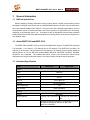
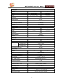
BNET-5304/5310 User’s Manual v1.00 BNET-5304/BNET-5310 User’s Manual V1.00 2011/11/20 Warranty All products manufactured by ICP DAS are under warranty regarding defective materials for a period of one year from the date of delivery to the original purchaser. Warning ICP DAS assumes no liability for damages resulting from the use of this product. ICP DAS reserves the right to change this manual at any time without notice. The information furnished by ICP DAS is believed to be accurate and reliable. However, no responsibility is assumed by ICP DAS for its use, or for any infringements of patents or other rights of third parties resulting from its use. Copyright All rights are reserved by ICP DAS Co., Ltd. 2012. Trademark The names used for identification only may be registered trademarks of their respective companies. Document Revision Version Author Date Description of Changes 1.00 Eugene 2012/11/20 First Released Revision 2 BNET-5304/BNET-5310 User’s Manual V1.00 2011/11/20 Table of Contents 1. General Information..................................................................................................................... 4 1.1 BACnet Introduction................................................................................................... 4 1.2 About BNET-5304 and BNET-5310........................................................................... 4 1.3 Hardware Specification .............................................................................................. 4 Hardware .......................................................................................................................................... 7 1.4 BNET-5304 Pin Assignment and Wire Connection ................................................... 7 1.5 BNET-5310 Pin Assignment and Wire Connection ................................................... 9 1.6 LED Indication.......................................................................................................... 11 1.6.1 Power LED ............................................................................................................... 11 1.6.2 Module Status indicator LED ................................................................................... 11 2. Web Based Configuration Tool ................................................................................................. 12 2.1 Device Selection ...................................................................................................... 12 2.2 Using Web-based Configuration Tool...................................................................... 12 2.3 Tab menu of Configuration Tool .............................................................................. 14 2.3.1 System ..................................................................................................................... 14 2.3.2 Modbus .................................................................................................................... 14 2.3.3 BACnet..................................................................................................................... 14 2.3.4 Modbus/BACnet Mapping ........................................................................................ 14 2.4 System tab ............................................................................................................... 15 2.4.1 System Process ....................................................................................................... 16 2.4.2 Network Settings...................................................................................................... 16 2.4.3 Uploading and Updating Firmware .......................................................................... 16 2.4.4 Change User Name & Password ............................................................................. 17 2.5BACnet tab 18 2.5.1 BACnet basic information configuration................................................................... 18 2.5.2 BACnet Object Types and instance settings ........................................................... 19 2.6BACnet Object tab..................................................................................................................... 20 3 BNET-5304/BNET-5310 User’s Manual 1. V1.00 2011/11/20 General Information 1.1 BACnet Introduction BACnet stands for Building Automation Control network which is a data communication protocol developed by ASHRAE, BACnet is known as "ANSI/ASHRAE standard 135-2001" and now also known as the international standard "ISO 16484-5." The protocol has been designed specifically to meet the communication needs of building automation and control systems for applications such as heating, ventilating, air-conditioning control…etc. Its purpose is also to standardize communications between building automation devices from different manufacturers, allowing data to be shared and equipment to work together easily. 1.2 About BNET-5304 and BNET-5310 The BNET-5304 and BNET-5310 are multi-function BACnet/IP modules. The BNET-5304 provides 6 AI channels, 1 AO channel, 4 DI channels and 4 DO channels. The BNET-5310 provides 4 AI channels, 2 AO channels, 3 DI channels and 3 DO channels. The modules contain number of BACnet objects (Device, AI, AO, BI, BO) with multiple BIBBS (DS-RP-B, DS-RPM-B, DS-WP-B, DS-WPM, DS-COV-B…etc.) supported. The modules also feature a built-in web server which allows remote configuration by using a regular web browser for an easy and safe access at anytime anywhere. 1.3 Hardware Specification Model BNET-5304 BNET-5310 System COM1 Reserved COM2 No use COM3 No use Ethernet 10/100 Base-TX Security ID and Password Built-in Watchdog Yes LED Indicator Power and Status Protocol BACnet BACnet/IP BACnet Objects 1 Device, 6 AI, 1 AO, 4 BI, 4 BO BIBB DS-RP-B, DS-RPM-B, DS-WP-B, DS-WPM-B, DS-COV-B, DM-DDB-B, DM-DOB-B, DM-DCC-B, DM-TS-B, DM-UTC-B, DM-RD-B 4 1 Device, 4 AI, 2 AO, 3 BI, 3 BO BNET-5304/BNET-5310 User’s Manual V1.00 2011/11/20 Analog Input Channel 6 4 Wiring Single-Ended Differential Range +/- 5 V, 0 ~ +5 V +/- 10 V Resolution 12-bit Sampling Rate 4 KHz Input Impedance 1 M Ohm Over Voltage Protection +/- 30 VDC Isolation Non-isolated Analog Output Channel Range 1 2 +/- 5V +/- 10 V Resolution 12-bit Output Capacity 20 mA Isolation Non-isolated Digital Input Channel 4 Contact Dry Contact 3 Dry On Voltage Level Close to GND Off Voltage Level Open Overvoltage Protection 30 VDC Digital Output Channel 4 Type 3 Open Collector Sink/Source (NPN/PNP) Sink Load Voltage +10 VDC ~ 40 VDC Max. Load Current 200 mA/channel at 25 °C Overload Protection 1.4 A Environmental Dimensions (W x L x H) 91mm x132mm x 52mm Operating Temp. -25 ~ +75 °C Storage Temp. -30 ~ +85 °C Humidity 5_90% PH, non-condesing Power Input Range +10V to +30+10V to +30VDC 5 BNET-5304/BNET-5310 User’s Manual Power Consumption 4.8W (0.2A @ 24VDC) 6 V1.00 2011/11/20 5.4W (0.2A @ 24VDC) BNET-5304/BNET-5310 User’s Manual V1.00 2011/11/20 2. Hardware 2.1 BNET-5304 Pin Assignment and Wire Connection BNET-5304 Pin Description Pin Description Pin Description Pin Description 1 F.G. 8 GND 15 DO.PWR 22 GND 2 GND 9 TxD 16 GND 23 Vin0 3 +VS 10 RxD 17 DI0 24 Vin1 4 -- 11 DO0 18 DI1 25 Vin2 5 -- 12 DO1 19 DI2 26 Vin3 6 -- 13 DO2 20 DI3 27 Vin4 7 -- 14 DO3 21 Vout0 28 Vin5 7 BNET-5304/BNET-5310 User’s Manual 8 V1.00 2011/11/20 BNET-5304/BNET-5310 User’s Manual V1.00 2011/11/20 2.2 BNET-5310 Pin Assignment and Wire Connection BNET-5310 Pin Description Pin Description Pin Description Pin Description 1 F.G. 8 GND 15 DI0 22 Vin0- 2 GND 9 TxD 16 DI1 23 Vin1+ 3 +VS 10 RxD 17 DI2 24 Vin1- 4 -- 11 DO0 18 GND 25 Vin2+ 5 -- 12 DO1 19 Vout0 26 Vin2- 6 -- 13 DO2 20 Vout1 27 Vin3+ 7 -- 14 DO.PWR 21 Vin0+ 28 Vin3- 9 BNET-5304/BNET-5310 User’s Manual 10 V1.00 2011/11/20 BNET-5304/BNET-5310 User’s Manual V1.00 2011/11/20 2.3 LED Indication BNET-5304/BNET-5310 provides two LEDs to indicate what situation is in the module. They are described as follows. 2.3.1 Power LED The BNET-5304/BNET-5310 needs +10 ~ +30 VDC power input and consumes 4.8W and 5.4W. The PWR LED (Power LED) will be turn on after applying power and it will be flashing two times per second. 2.3.2 Module Status indicator LED The STATUS LED indicates the communication status of the BNET-5304/BNET-5310. following description shows the conditions of error status. Green light flashes: BACnet/IP Client is communicating with BNET-5304/BNET-5310. Red light flashes: Time out or unknown Object/Service error. Red light on: BNET-5304/BNET-5310 initial error. 11 The BNET-5304/BNET-5310 User’s Manual V1.00 2011/11/20 3. Web Based Configuration Tool This chapter is to describe the web structure and software operating interfaces. BNET-5304/BNET-5310 provides Web-based configuration for the BACnet devices and objects settings. The functions include: System information and configuration Network settings BACnet objects configuration and management 3.1 Device Selection BNET-5304: BACnet/IP Multi-function I/O Module with 6 AI, 1 AO, 4 BI, and 4 BO. BNET-5310: BACnet/IP Multi-function I/O Module with 4 AI, 2 AO, 3 BI, and 3 BO 3.2 Using Web-based Configuration Tool Connect the BNET-5304/BNET-5310 to network, and use standard web browser (Internet Explorer, Mozilla Firefox) to launch the user interface. The default link and network settings are as followed: Web Address: http://192.168.255.1 IP Address: 192.168.255.1 Subnet Mask: 255.255.0.0 Gateway: 192.168.0.254 For security reason, user will have to login with user name and password before entering the configuration pages. The default user name and password are admin and admin. 12 BNET-5304/BNET-5310 User’s Manual V1.00 2011/11/20 Figure 1. Logon screen Screen opened as image shown in Figure 2, if success login. Select a hardware to enter a correspond page. Figure 2. Module or Device selection page 13 BNET-5304/BNET-5310 User’s Manual V1.00 2011/11/20 3.3 Tab menu of Configuration Tool The configuration tool had divided into four sections System, Modbus, BACnet, and Modbus/BACnet Mapping. Please refer to the following clause for detail information. 3.3.1 System System information and settings consist of BACnet Firmware status and operations (start or stop) Network settings Firmware Updating User name and password configuration 3.3.2 Modbus The section is only available for GW-549x series. 3.3.3 BACnet BACnet Server Configuration consists of BACnet/IP Port Setting Management of the BACnet basic information Instance Table (shows the number of object on the device) 3.3.4 BACnet Object Definition and management of BACnet Objects 14 BNET-5304/BNET-5310 User’s Manual V1.00 2011/11/20 3.4 System tab As shown in Figure 3, the system tab provides an operation mode, a network setting, firmware updating, and user account settings. 1. System Process: Monitors the BACnet Firmware running status, and operate its’ state (start or stop) 2. Network Settings: LANs are provided for BACnet/IP protocol. 3. Upload and Updating Firmware: Uploading and updating firmware. 4. Change User Names & Password: Modify the current user name and password. Figure 3. System tab 15 BNET-5304/BNET-5310 User’s Manual 3.4.1 V1.00 2011/11/20 System Process Figure 4 shows the System Process frame. The Process column shows the firmware name and the Operations column shows the firmware status. The Start/Stop buttons are able to start/stop the firmware by clicking the buttons. Figure 4. System Process 3.4.2 Network Settings Network Settings consists an Ethernet LAN settings provided for BACnet/IP protocol. All information isn’t saved until clicking the Save Settings button. User will need to reboot the system or restart it to apply the changes. After hardware rebooted, user will also need to re-open the web user interface. Figure 5. Network Settings 3.4.3 Uploading and Updating Firmware Figure 6 shows the Upload and Update Firmware tool. The current firmware version is showed. The firmware can also be updated from a .fw file downloaded from ICP DAS by choosing the file path and click “Upload Firmware” to upload file to device. After .fw file uploaded, click “Update Firmware” button to update firmware. After firmware updated, please restart the BNET-5304/BNET-5310 and User Interface. 16 BNET-5304/BNET-5310 User’s Manual V1.00 2011/11/20 Figure 6. Import/Export/Updating Firmware 3.4.4 Change User Name & Password The section provides an interface which allows user to modify the user name and password. User will need to reboot the system or restart it to apply the changes. Figure 7. Change User Name & Password 17 BNET-5304/BNET-5310 User’s Manual V1.00 2011/11/20 3.5 BACnet tab The Figure 8 shows the BACnet Device configuration. The detail description as follows: 1. BACnet basic information and configuration 2. BACnet Object Types and max instance information Figure 8. BACnet tab 3.5.1 BACnet basic information configuration Figure 9 shows the BACnet basic information, consisting of Protocol, Communication and Device Object properties settings. 18 BNET-5304/BNET-5310 User’s Manual V1.00 2011/11/20 Figure 9. BACnet basic information Port: BACnet Port. Default port is 47808 (0xBAC0) ID: Device_Identifier property, range from 0 to 4194302 Name: The device name showed on BACnet network. Retry: Number_Of_APDU_Retries property Timeout: APDU_Timeout property UTC_Offset: The time offset from Coordinated Universal Time Location: Location property Description: Object Description property 3.5.2 BACnet Object Types and instance settings The BNET-5304/BNET-5310 supports several types of standard BACnet Objects including Analog Input, Analog Output, Binary Input, Binary Output and Device. Figure 10 shows the 9 types of BACnet Objects, the 3-column sub fame consisting of Type, Maximum, and Instance number. Figure 10. BACnet Object list 19 BNET-5304/BNET-5310 User’s Manual V1.00 2011/11/20 3.6 BACnet Object tab The BACnet Object tab provides a list of BACnet Objects, as shown in Figure 16. 1. 2. BACnet Object type list BACnet Object list Figure 11. BACnet Object tab 20 BNET-5304/BNET-5310 User’s Manual V1.00 2011/11/20 3.6.1 BACnet Object Type List Select an object type from Object Type list to show the corresponding BACnet object in the Object Table. After object type selected , it should be showed in the textbox. 3.6.2 BACnet Object Type List The Object Table consists varies BACnet object properties which allow user to modify it. Please refer to description below about each column in the table. BACnet Object Table: Object Identifier: BACnet Object_Identifier property Device: Modbus Device name Point: Indicates the channel type of the module. Index: Indicates the channel number of the module. Object Name: BACnet Object_Name property COV Increment: COV_Increment property. For the Analog object type only. COVPeriod: The period time of COVNotification required service. Unit: BACnet Unit property. For the Analog object type only. Polarity: BACnet Polarity property mode. For the Binary object type only. Description: BACnet Description property Figure 20. Mapping 21