1
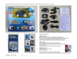
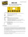
BR1100
Controller Operation
Solar Powered Chemical Injection Pump
PUMP CONTROLLER USER MANUAL
A. USER INTERFACE
A.1 SWITCH Defines
S
Accesses menu system and cycles between stroke-time, stroke-frequency and duty-cycle
UP
Increments stroke-time and stroke-frequency values
DOWN
Decrements stroke-time and stroke-frequency values
START
Starts motor ON/OFF cycle mode
PRIME
Starts motor Prime mode
STOP
Terminates motor ON/OFF cycle or Prime mode or exits from menu system
A.2 LED State Defines
STROKE
ON indicates stroke-time is selected while in menu system
FREQ
ON indicates stroke-frequency is selected while in menu system
DUTY
ON indicates duty-cycle is selected while in menu system
RUN
ON indicates motor is running in motor ON/OFF cycle or Prime mode, OFF otherwise
PRIME
ON indicates motor is running in Prime mode
CHARGE
ON indicates battery is charged, blinking at 1 sec interval indicates battery is charging and OFF
indicates solar-panel is not present or there is insufficient light for charging
A.3 SEVEN-SEGMENT DISPLAY Strings
oF
Idle state, system is not in motor ON/OFF cycle or Prime mode or within menu system
on
Motor ON/OFF cycle mode
Pr
Motor Prime mode
F1
Motor short-circuit fault code
F2
Low-battery fault code
B. MOTOR MODES
The motor can run in either of two modes – motor ON/OFF cycle or Prime mode.
In motor ON/OFF cycle mode, the motor and the RUN LED stays ON for a time according to stroke-time and stays
OFF for a time according to stroke-frequency and stroke-time. This cycle is repeated until the STOP switch is
pressed. In Prime mode, the motor and the RUN LED stays ON until 60 seconds have elapsed or the STOP switch
is pressed. Motor ON/OFF cycle mode is initiated by pressing the START switch while Prime mode is initiated by
pressing the PRIME switch. On-the-fly mode changes are permitted between motor ON/OFF cycle and Prime
modes without first hitting the STOP switch.
The 7-segment display shows "on" when motor ON/OFF cycle mode is selected and "Pr" when Prime mode is
selected. If either mode is terminated by using the STOP switch or when Prime mode times-out after 60 seconds,
the display shows "oF" , indicating system is now in idle state.
The system remembers if it was in motor ON/OFF cycle mode and powers up in ON/OFF mode if system was in
ON/OFF mode when power was interrupted.
C. MENU SYSTEM
The menu system user-interface consisting of the S,UP & DOWN switches, 7-segment display and STROKE,
FREQ & DUTY indicator LEDs, allows the user to change the stroke-time and stroke-frequency for motor
ON/OFF cycle mode. Duty cycle cannot be changed directly in the menu system and the UP/DOWN switches
have no effect. Menu system changes are allowed only if the system is NOT in motor ON/OFF cycle mode.
Pressing the menu switch while in motor ON/OFF cycle mode allows the user to view the stroke-time, strokefrequency and duty cycle values but the UP/DOWN switches have no effect. Menu system functions normally if
the system is in Prime mode.
Pressing the S switch turns ON the STROKE LED and displays the stroke-time. The stroke-time is the length of
time that the motor turns on for during each cycle. Pressing UP or DOWN switch while in stroke-time sub-menu
allows the stroke-time to be changed from 0.1 to 9.9 seconds. Pressing the S switch again will turn ON the FREQ
LED and display the stroke-frequency. The stroke-frequency is the number of cycles per minute that occur.
Pressing UP or DN switch while in stroke-frequency sub-menu allows the stroke-frequency to be changed from 0.1
to 9.9 cycles per minute. Depending on the stroke-time selected, there is a upper limit to the maximum strokefrequency that can be selected. Pressing the S switch again will turn ON the DUTY LED and display the calculated
duty-cycle calculated from the selected stroke-time and stroke-frequency values. Duty-cycle values in the 10.0% to
99.9% range are displayed as 10 to 99, values in the 0.1% to 9.9% range are displayed as 0.1 to 9.9 while values
less than 0.1% are displayed as 0.0. Pressing the S switch again takes the user back to the stroke-time sub-menu.
Useful Formulas'
Duty Cycle = (Stroke * Frequency *100) / 60
Time between Start Cycles (in seconds) = 60 / frequency
Stroke = 0.6 * Duty Cycle / Frequency
Frequency = 0.6 * Duty Cycle / Stroke
The menu system is exited under the following conditions 1. No switch has been pressed for 5 secs – menu time-out occurs and system exits to last state
2. STOP switch is pressed – system exits to idle state
3. START switch is pressed – system exits to motor ON/OFF cycle mode
4. PRIME switch is pressed – system exits to motor Prime mode
Selected stroke-time and stroke-frequency values are written to EEPROM before a menu exit.
D. SLEEP MODE
If no switch has been pressed for 30 seconds, the seven-segment display & LEDs are blanked and system enters
into sleep mode to conserve power. If motor ON/OFF cycle mode or Prime mode had been selected before sleep,
selected mode continues to run in sleep mode. Exiting out of sleep mode is accomplished by pressing any switch.
The system will wake up and display the last state before sleep mode– "oF" for idle state, "on" for motor ON/OFF
cycle mode or "Pr" for Prime mode.
E. FAULT CONDITIONS
E.1 Motor short-circuit
While in motor ON/OFF cycle mode and motor is running, if a short occurs across the motor windings, the system
shuts off the drive to the motor and displays fault condition message "F1". During subsequent ON/OFF cycles, the
system will keep on trying to turn on the motor. If the fault condition goes away, the fault condition message is
replaced by motor ON/OFF cycle mode message "on".
While in Prime mode, if a short occurs across the motor windings, the system shuts off the drive to the motor and
displays fault condition message "F1". If the PRIME switch is pressed again, the system will try to turn on the
motor again. If the fault condition goes away within 60 secs, the fault-condition message is replaced by Prime
mode message "Pr".
E.2 Low-battery
The system displays "F2" if the battery voltage falls below 11.5V. System operation continues to run normally
under low-battery fault condition. Low-battery fault condition has lower priority than motor short-circuit fault
condition.
F. BATTERY CHARGING
F.1 Float Charging
The system monitors the battery voltage at 1 sec intervals and performs temperature-compensated float charging
assuming a solar-panel is present and there is sufficient light. The CHARGE LED blinks at 1 sec intervals when
battery is being charged and turns steady ON when battery reaches float voltage at the given temperature.
F.2 Battery Equalization
Temperature-compensated battery equalization is performed automatically every 7 days until battery voltage
reaches equalization voltage or system has been in equalization mode for 24 hours, whichever is earlier.
During equalization mode, the RHS decimal point of 7-segment display is turned ON for "on", "oF",
Pr", "F1" or "F2" message displays. Holding any button pressed when system is powered up displays "EE"
and forces system into equalization mode.
G. POWER CONNECT / DISCONNECT
G.1 Controller Power Connect / Disconnect
The power to the controller can only be connected or disconnected by the power source to the controller.
Connecting / disconnecting the 4 pin connector from the battery and solar panels will connect or disconnect the
power to the controller.
G.2 Motor Power Connect / Disconnect
The power to the motor can be connected or disconnected by either connecting or disconnecting the power to the
controller as indicated in G.1, or by connecting / disconnecting the 2 pin connector on the controller to the motor.