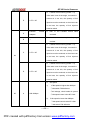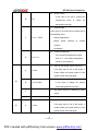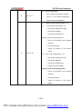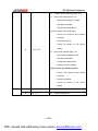
1
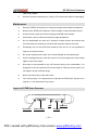
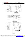
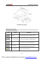
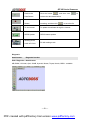
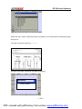
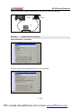
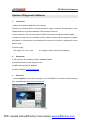
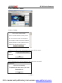
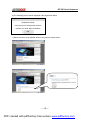
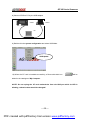
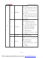
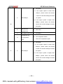
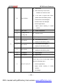
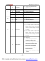
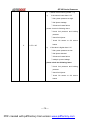
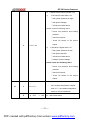
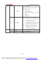
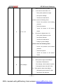
USER MANUAL
STAR Auto Scanner
_______________________________________________
Copyright ©2005 by Autoboss Tech. Inc.
PDF created with pdfFactory trial version www.pdffactory.com
STAR Auto Scanner
Trademark Information
is a registered trademark of Autoboss Tech. Inc. in China and other
countries. All other AUTOBOSS trademarks, service marks, domain names, logos, and
company names referred to in this manual are either trademarks, registered trademarks,
service marks, domain names, logos, company names of or are otherwise the property of
AUTOBOSS or its affiliates. In countries where any of the AUTOBOSS trademarks, service
marks, domain names, logos and company names are not registered, AUTOBOSS claims
other rights associated with unregistered trademarks, service marks, domain names, logos,
and company names.
Other products or company names referred to in this manual may be trademarks of their
respective owners. You may not use any trademark, service mark, domain name, logo, or
company name of AUTOBOSS or any third party without permission from the owner of the
applicable trademark, service mark, domain name, logo, or company name. You may
contact AUTOBOSS by sending e-mail to [email protected], or writing to 5/FL, East,
Bldg. 304, Shangbu Industrial Park, Futian, Shenzhen, PRC, to request written permission
to use materials on this manual for purposes or for other questions relating to this manual.
Copyright information
Copyright© by Autoboss Tech. Inc. All rights reserved. No part of this publication may be
reproduced, stored in a retrieval system, or transmitted in any form or by any means,
electronic, mechanical, photocopying, recording or otherwise, without the prior written
permission of AUTOBOSS. The information contained herein is designed only for the use of
this unit. AUTOBOSS is not responsible for any use of this information as applied to other
units. Neither AUTOBOSS not its affiliates shall be liable to the purchaser of this unit or third
parties for damaged, losses, costs, or expenses incurred by purchaser or third parties as a
result of: unauthorized modifications, repairs, or alternations to this unit, or failure to strictly
comply with AUTOBOSS operating and maintenance instructions.
----1----
PDF created with pdfFactory trial version www.pdffactory.com
STAR Auto Scanner
AUTOBOSS shall not be liable for any damages or problems arising from the use of any
options or any consumable products other than those designed as Original Products or
AUTOBOSS Approved Products by AUTOBOSS.
Disclaimer
To take full advantage of the unit, you should be familiar with the engine.
All information, illustrations and specifications contained in this manual are based on the
latest information available at the time of publication. The right is reversed to make changes
at any time without notice.
----2----
PDF created with pdfFactory trial version www.pdffactory.com
STAR Auto Scanner
Table of Contents
Introduction······························································································································· 4
Features···································································································································· 4
Precaution on operation ··························································································4
Maintenance······························································································································ 5
Layout of STAR Auto Scanner···································································································· 5
Explanation of buttons ··············································································································· 7
Diagnosis ·································································································································· 8
Update the diagnosis software···································································································· 17
Vehicle Diagnosis Description ···································································································· 21
FAQ·········································································································································· 24
Appendix 1: about VIN··············································································································· 28
Appendix 2: Block and parameter for Volkswagen vehicle····························································
The Block number of Audi A8 (MPI 2.8L 2Valves)····································································· 31
The Block number of Passat B5································································································· 42
The Block number of Audi 100/200 2.6E ·················································································· 62
Lambda control table ················································································································· 75
----3----
PDF created with pdfFactory trial version www.pdffactory.com
STAR Auto Scanner
Introduction
STAR Auto Scanner is the latest automotive diagnostic innovative product based on both
automotive electronics and information technology.
Features
Convenient to Update
J
The function of software update via Internet makes it easy for customer to get
the latest diagnostic program and keep pace with the development of
automotive technology.
J
Multilanguage display makes operation convenient in different countries and
areas.
Advanced
J
STAR Auto Scanner is the most advanced automobile diagnostic unit in the
world at present. It is compactly designed and with large LCD touch screen.
Mini printer makes the operation easy.
J
The product is combination of the automobile industry and the communication
technology, which STAR Auto Scanner the new development trend in the
automobile diagnosis field. It provides a new way of automotive diagnosis for
vehicle service station.
Precaution on operation
J
Try your best to keep the screen facing upward and leveled during the testing.
J
Be careful when plugging and unplugging the main cable and diagnostic
connector. Tighten the screw before operation so as to avoid unexpected
disconnecting and/or damage to the port.
J
Hold the STAR Auto Scanner main unit during the operation. Avoid hitting.
Unplug the power after operation.
J
Do not insert and pull out CF memory card too frequently. Press ejector button
before pulling out the CF memory card. Insert the CF memory card into the CF
memory card slot, keep the face labeled ”Hi-Speed” upward, and make sure the
----4----
PDF created with pdfFactory trial version www.pdffactory.com
STAR Auto Scanner
card is fully seated.
J
Hold the connector when plug or unplug it. Do not pull the cable for unplugging.
Maintenance
J
Store the STAR Auto Scanner on a flat and dry place with suitable temperature.
J
Never put the STAR Auto Scanner in direct sunlight or near the heating source.
J
Prevent smoke, water and oil form entering the STAR Auto Scanner.
J
Avoid shock, dust, moisture and extremely high temperature.
J
Do not disassemble the main unit. Clean the outside surface and screen with
soft cloth when the machine is turned off and the power cable is removed.
J
Periodically turn on the STAR Auto Scanner main unit if it is not operated for
long time to avoid moisture.
J
Do not put anything on the main unit to avoid damage to the internal parts.
J
Use the equipped stylus to click the screen. Do not use fingernail or other sharp
object to touch the screen.
J
Dust may be accumulated on the LCD screen owing to the electrostatic. It is
suggested to buy the special LCD screen wiper to clean the screen gently. Do
not wipe the screen with bare finger.
J
Never use chemicals to clean the screen.
J
Turn off the power if it is expected not to operate the STAR Auto Scanner for a
long time. It can extend the life of screen.
Layout of STAR Auto Scanner
LAN
Touch Pen
USB Port
CF Card
Paper Outlet
----5----
PDF created with pdfFactory trial version www.pdffactory.com
STAR Auto Scanner
Touch Screen
Keys
ON/OFF Switch
Power Port
Diagnosis Port
Label
Scope Port
Mini printer
Level for printer
----6----
PDF created with pdfFactory trial version www.pdffactory.com
STAR Auto Scanner
Fax Paper
Insert
Insert
Illustration for printer
Explanation of buttons
The descriptions of the button:
Button
Function
Description
Paper-in
To feed the paper through the Paper-in Button
Print current page
To print the current page at the diagnosis mode
Turn the screen
Convenient for viewing the diagnosis result
180°
To save files after recording the live data. Enter the
Save the files
file name and save the file in order to recall.
Open the files
To open the files saved before.
----7----
PDF created with pdfFactory trial version www.pdffactory.com
STAR Auto Scanner
Retrieve the
Click the button
Data Stream
retrieve the data saved before.
Record the data
To record the live data. Enter the file name after
Stream
recording, and then click
To the Internet
To update the software through the Internet.
GPRS Update
GPRS internet update
, and then click
to save the file.
Working at the
PC-A8 working mode
mode of PC-A8
Diagnosis
AutoScanner:
Diagnosis function
Path: Diagnosis----AutoScanner
MB, BMW, VW/Audi, Opel, SAAB, Hyundai, Nissan, Toyota, Honda, OBDII…available
----8----
PDF created with pdfFactory trial version www.pdffactory.com
to
STAR Auto Scanner
Setting
User Information:
Workshop Info
Path: Setting----User Information
The user can record the repair information including the name, telephone number, fax and
address etc. The information input can be realized via the keyboard. Press the button [Keys]
and then select the icon of keyboard.
STAR Auto Scanner prompts the user to input the workshop information. If wrong number is
entered, click [←] to delete the wrong number and input the correct one.
Language >:
Language switchover
Path: Setting----Language
NOTE: The default is English. You can select to Chinese by pressing the button.
----9----
PDF created with pdfFactory trial version www.pdffactory.com
STAR Auto Scanner
Contrast:
Adjust the contrast and brightness
Path: Setting----Contrast
NOTE: The screen is set the optimum contrast in the factory before delivery.
Follow the procedures listed below if the screen is too white or too dark during the testing:
1. Select the item [Setting], and then select [Display], the following page will pop out:
White
Black
OK
2. Adjust the optimum contrast with the pen and press [OK].
Touch Set:
Touch screen calibration
Path: Setting----Touch Set
NOTE: The screen is calibrated in the factory before delivery. Do not touch the screen
without purposes since it will affect the accuracy of the screen. The following procedures will
be carried out when the screen is not accurate:
1.
Turn off STAR Auto Scanner first.
2.
Wait for more than 5 seconds and then turn on STAR Auto Scanner.
3.
Press the company logo AUTOBOSS with the pen for several seconds till the following
picture displayed (see Step 1):
----10----
PDF created with pdfFactory trial version www.pdffactory.com
STAR Auto Scanner
┼ Please click cross
(See Step 1)
4.
Press the center of the cross with the pen and then the following page will be displayed
(see Step 2):
┼ Please click cross
(See Step 2)
Repeat the step mentioned above. STAR Auto Scanner returns to the original configuration.
PowerPoint:
Education function for the current information transmitted to the PC
via serial port
Path: Setting----PowerPoint
The customer can make education DEMO anywhere at the mode of PowerPoint.
Cancel PPT
Run the file of Powerpoint.exe to display the page shown on the left. Click the button to
capture the pictures. The screen of the STAR will transfer the information to PC before
Clicking the touch screen.
----11----
PDF created with pdfFactory trial version www.pdffactory.com
STAR Auto Scanner
Connect the cables as the picture shown on the left by the 9-pin cable.
The information is sent to PC. The dialogue box will disappear when all the information is
transferred.
Information
Internet Update:
Same function as
Path: Setting---- Internet Update
Information
Connecting Server…
Press touch screen to …
USB Update:
USB Card Reader Mode
Path: Setting-----USB Update
Update the software via the USB mode.
----12----
PDF created with pdfFactory trial version www.pdffactory.com
STAR Auto Scanner
After selecting the USB Update, the following message will pop out:
USB Update
USB Card Reader Mode
Note: Turn off the power after using.
Information
Circuit: Consult the electric circuit
Path: Information-----Circuit
To provide the reference for the car repair. After selecting the item [Circuit], the following
page will pop out:
----13----
PDF created with pdfFactory trial version www.pdffactory.com
STAR Auto Scanner
Select the year, model, make and system according to your requirement; the following page
will pop out:
View the circuit by the button of ←↑→↓
Print the circuit after connection the cable as following:
Information
Printing Report…
----14----
PDF created with pdfFactory trial version www.pdffactory.com
STAR Auto Scanner
And the connections between STAR and PC and printer is shown as following:
STAR
Printer
PC
Dictionary:
English--Chinese dictionary
Path: Information-----Dictionary
Enter the words to be searched through the in-built keyboard:
----15----
PDF created with pdfFactory trial version www.pdffactory.com
STAR Auto Scanner
Keys
The following page listed below illustrates the keys on the touch screen:
In-built keyboard
----16----
PDF created with pdfFactory trial version www.pdffactory.com
STAR Auto Scanner
Update of Diagnostic Software
1.
Precaution
1) Select and install the diagnostic card correctly.
2) Ensure the reliable cable connection and power supply. Avoid the card damaged or slow
update speed due to power breakdown or the harness connection.
3) Do not touch the PC and main body of STAR Auto Scanner during the software update.
4) Check the cards after the software update. Please re-download the diagnostic program
and update or contact with the local distributor if the screen is a mass or displaying the main
body number.
5) Power supply
DC voltage: DC 12.5~13.5V
2.
AC voltage: AC220V (Via WU-60 Stabilizer)
Preparation
1) PC computer with operating system: WIN98/WIN2000
2) STAR Auto Scanner and diagnostic card
3) USB Cable and WU-60 Stabilizer
4) Visit the website: www.autoboss.net
3.
Procedure
1) Select English to enter the homepage of the AUTOBOSS or enter the website directly
from the address bar: http://www.autoboss.net
----17----
PDF created with pdfFactory trial version www.pdffactory.com
STAR Auto Scanner
2) Select Download for Update
3) Select I accept.
Terms of Service of Autoboss Website
The service of Autoboss Website is provided by Autoboss
Tech. Inc. on the basis of its rules, terms and regulations.
User must agree to all of the service terms and complete the
registration procedure so as to be a registered user. kind of
registered user in the Autoboss Website up to now.
4) Enter the mobile number and password and press [OK] to submit.
<Enter the mobile number>
Mobile:
Password
OK
5) The following picture will be displayed if the registration succeeded!
Registration
Signed out successfully!
The password has been sent to your email.
Please check it!
OK
----18----
PDF created with pdfFactory trial version www.pdffactory.com
STAR Auto Scanner
6) The following picture will be displayed if the registration failed!
Registration
Registration failed!
You have input a wrong serial number!
Contact your local agent for details!
OK
7) Select the items to be updated. Refer to the pictures shown below:
----19----
PDF created with pdfFactory trial version www.pdffactory.com
STAR Auto Scanner
8) Connect STAR to PC by the USB adaptor.
STAR
Printer
PC
9) Double click the system configuration and select USB Mode.
USB Update
10) When the CF card is installed successfully, a Removable disk icon
will be
added in the catalogue of My Computer.
NOTE: Do not unplug the CF card reader/writer from the USB port while its LED is
blinking, otherwise data would be damaged!
----20----
PDF created with pdfFactory trial version www.pdffactory.com
STAR Auto Scanner
Vehicle Diagnosis Description
Diagnostic socket location
The diagnostic socket of Volkswagen vehicle is located in the cab under the instrument at
the driver side.
Pin definitions
4pin diagnostic socket
The 4pin diagnostic socket is shown as following:
Black
B+
B-
1
2
White
3
4
K line
L line
Pin
Definition
1
L line
2
K line
3
Grounding
4
Power
16pin diagnostic socket
Pin
Designation
Pin
Designation
1
TCU
9
ASC
2
BUS+
10
EMPTY
3
EMPTY
11
A/C
4
GND
12
SRS
5
GND
13
EMPTY
6
TCS
14
EMPTY
7
K-line
15
L-line
8
ABS
16
Battery
Select Diagnostic Adaptor
Various diagnostic connectors are supplied with STAR Auto Scanner. The principle for the
cable connection is same. Select a specific connector according to the tested vehicle.
----21----
PDF created with pdfFactory trial version www.pdffactory.com
STAR Auto Scanner
1: A hole used to connect the power
3
2: Connect with the main cable
3: Connect to the diagnostic socket
1
2
There are two ways to get power voltage for testing:
Method 1: From the WU-60 adaptor
******Insert the connector into the
hole on the side of any adaptor to
get power from WU-60 adaptor
when testing.
Method 2: From the battery
******Insert the connector into the
hole on the side of any adaptor to
get power after the connection
with the vehicle battery when
testing.
Let’s take Volkswagen vehicle as example to describe the test procedure.
Please select the Volkswagen 4pin or 16pin diagnostic adaptor.
NOTE: The test procedure for different vehicle make is similar. Please refer to the described
procedure and the screen prompts when diagnosing other vehicles.
----22----
PDF created with pdfFactory trial version www.pdffactory.com
STAR Auto Scanner
Volkswagen vehicle is usually equipped with 4pin or 16pin diagnostic socket.
Path: Diagnosis-----Auto Scanner
Select [European] and click the icon of
Volkswagen on the vehicle make
menu. The screen will be displayed as
shown on the left:
Button description:
[EXIT] or X: Go back to the previous
menu.
After selecting Volkswagen, the left
screen will pop out. See the left page.
Select the item to be tested by the
arrow ↑ and ↓
Button description:
[EXIT] or X: Go back to the previous
menu.
[↑ ] or [↓ ]: To scroll the testing items
one by one for view.
After selecting the item, the left picture
will be displayed for reference.
If the connection is good, the testing
will continue. Otherwise, the following
page will be display after pressing
[HELP].
----23----
PDF created with pdfFactory trial version www.pdffactory.com
STAR Auto Scanner
Button description:
[EXIT] or X: Go back to the previous
menu.
FAQ
STAR Auto Scanner is a hi-tech product. With the development of modern automotive
industry, more and more new technology will be adopted and there may be questions during
operation. Read the user’s manual to get the answer whenever you have any questions, or
contact our Customer Service Center for help.
Here we list some frequently asked questions and answers relating to STAR Auto Scanner.
About Software Update
Question: Why can’t the main unit recognize the replaced CF card?
Answer: There are two possible reasons:
1.
The original 64M CF card has not been fully copied. Please delete the incomplete file
and copy again.
2.
The CF card is not compatible with the CF card. Mono-functional CF card is better in
such situation.
Question: How to make a new STAR CF card when the data in old one is lost or damaged?
Answer: In case STAR CF card is damaged and the program in the card cannot be read,
please follow the listed procedures to make a new CF card:
1.
Purchase same model CF card from the market.
----24----
PDF created with pdfFactory trial version www.pdffactory.com
STAR Auto Scanner
2.
Format the STAR CF card.
3.
Download the software program from autoboss website.
4.
Connect STAR Auto Scanner and PC through with the USB cable for software update.
About Hardware
Question: Why does the saved data disappear?
Answer: Your CF card is damaged.
Question: The screen does not respond or responds wrongly when I click it with pen. What
should I do?
Answer: It is necessary to calibrate the screen. Please refer to the section “Touch Set” in
the User’s Manual.
Question: What can I do when the screen is confused?
Answer: Please exit the current interface and run it again. If the problem still exits, please
restart the system.
Question: How to know what applications (interfaces) are opened?
Answer: Click the active taskbar icon, then the pop-up list will display the applications
(interfaces) opened.
Question: Why can’t I do operation in current interface?
Answer: There are two possible reasons:
1.
Your current interface has exited illegally. In this situation, you may not see the name of
the application (interface) in the pop-up list when you click the active taskbar icon.
2.
The system is busy, please wait patiently, or click the active taskbar icon to switch to
another application.
Question: Why does the LCD screen respond so slowly?
Answer: It is because the ambient temperature is close to the lower limit of operating
----25----
PDF created with pdfFactory trial version www.pdffactory.com
STAR Auto Scanner
temperature range (0~50℃). In this situation, it is necessary to warm up the machine for 20
minutes before testing.
Question: The screen keeps blank after flashing when the machine is turned on. What
should I do?
Answer: Take out the CF card and restart the machine to see if there is normal display. If the
display is normal when the CF card is taken out, the CF card should be replaced. If the
screen is still blank, please contact the local agent.
Question: Why does the system prompt that “checking CF card” when the machine is turned
on?
Answer: The possible cause is that no CF card is in the machine or CF card is inserted
improperly or damaged. If it is damaged, it is necessary to make a new one.
Question: What should I do if I can’t get into the diagnostic interface during test?
Answer: The possible cause is that no CF card is in the machine or CF card is inserted
improperly or damaged. If it is damaged, it is necessary to make a new one.
Question: Why can’t the data be inputted after the keyboard is activated?
Answer: The position where the cursor lies can’t be edited. Or you have not activated the
cursor on the input position. Please use the pen to click the part to edit. When the cursor
twinkles, you can input the data.
About System Setting
Question: The screen is too white and characters cannot be seen. What is the reason and
what should I do?
Answer: It may be caused by improper contrast. Please refer to the section “Contrast” to
adjust the contrast.
Question: The screen is inactive after the cross cursor appears on the screen. Why?
----26----
PDF created with pdfFactory trial version www.pdffactory.com
STAR Auto Scanner
Answer: The system is calibrating the touch screen. The machine will work after the screen
is calibrated. Refer to the section “Touch Set” in User’s Manual.
Question: Why does the screen flicks during engine starting?
Answer: It is caused by the electromagnetic interference. No problem with STAR Auto
Scanner.
Question: Why is operation interrupted during diagnosis?
Answer: It may be caused by electromagnetic interference or incorrect connection of
connector.
Question: Why is there no response from vehicle ECU at communication?
Answer: Make sure that the voltage of vehicle battery, ignition timer and idle speed are in
standard range; the throttle is in the closed position; and all electric devices, such as A/C,
headlight, stereos etc, are turned off.
Question: Some systems cannot be diagnosed. Why?
Answer: The diagnostic socket for the system on some early vehicle may be separated.
Refer to the vehicle instruction manual.
Question: Why are there two many trouble codes?
Answer: It may be caused by poor contact or poor grounding. Make sure that the vehicle
model/year is selected correctly and the vehicle is equipped with the system.
----27----
PDF created with pdfFactory trial version www.pdffactory.com
STAR Auto Scanner
Appendix 1: about VIN
Every vehicle has a unique VIN (Vehicle Identification Number). The VIN number is stamped
onto a small metal plate and is attached to the drivers side of the dash where it meets the
window. The VIN allows the Department of Motor Vehicles or the Department of
Transportation to keep track of the vehicles registered owner.
Police also use this number to verify that a vehicle has not been stolen and is in the
possession of the original owner. However, it takes professional thieves only seconds to
replace this plate with one from a legally purchased junk car of the same make and model.
Vehicle Identification Number (VIN)
What is it?
Vehicle identification number (VIN) is the automotive equivalent of human "DNA".
It sets the vehicle apart from the millions of other vehicles out there. In recent times it has
been reflected in 17 digit characters. It displays a car’s uniqueness and heritage and
provides a form of "factory to scrap yard" identification. It can be used to track recalls,
registrations, warranty claims, thefts and insurance coverage. Each character or digit has a
particular purpose.
History of the VIN
Detroit automobile manufacturers began stamping and casting identifying numbers on cars
and their parts in the mid 1950's . The primary purpose of this vehicle identification number
(VIN) was to give an accurate description of the vehicle when mass production numbers
were STAR Auto Scanner to scale in very significant numbers. The early VIN’s came in a
range of variations depending on the individual manufacturer at that time.
----28----
PDF created with pdfFactory trial version www.pdffactory.com
STAR Auto Scanner
In the early 1980's the U.S. National highway Traffic Safety Administration (USDOT)
required that all road vehicles must contain a 17 character VIN. This established the
standard fixed VIN system which major vehicle manufacturers use currently. The result was
a unique "DNA" style number for each individual vehicle rolled off the assembly line.
The Vehicle Identification Number was originally described in ISO Standard 3779 in
February 1977 and last revised in 1983. The ISO-VIN was designed to identify motor
vehicles, trailers, motorcycles and mopeds and consists of several parts described below.
How to read a VIN
1st character- Identifies the country in which the vehicle was manufactured.
For example: U.S.A.(1or 4), Canada(2), Mexico(3), Japan(J), Korea(K), England(S),
Germany(W), Italy(Z)
2nd character- Identifies the manufacturer. For example; Audi(A),BMW(B), Buick(4),
Cadillac(6),
Chevrolet(1),
Chrysler(C),
Dodge(B),Ford(F),
GM
Canada(7),
General
Motors(G), Honda(H), Jaquar (A), Lincoln(L), Mercedes Benz(D), Mercury(M), Nissan(N),
Oldsmobile(3), Pontiac(2or5), Plymouth(P), Saturn(8), Toyota(T), VW(V), Volvo(V).
3rd character- Identifies vehicle type or manufacturing division.
4th to 8th characters- VDS - Vehicle Descriptor Section. These 5 characters occupy
positions 4 through 8 of the VIN and may be used by the manufacturer to identify attributes
of the vehicle. Identifies vehicle features such as body style, engine type, model, series, etc.
9th Character-The check digit "character or digit 9" in the sequence of a vehicle
identification number (VIN) built beginning with model year 1981 (when the 17 character digit
format was established) can best be described as identifying the VIN accuracy.
A check digit shall be part of each vin (since 1981) and shall appear in position nine (9) of the
VIN on the vehicle and on any transfer documents containing the vin prepared by the
----29----
PDF created with pdfFactory trial version www.pdffactory.com
STAR Auto Scanner
manufacturer to be given to the first owner for purposes other than resale. Thus, the vins of
any two vehicles manufactured within a 30 year period shall not be identical. The check digit
means a single number or letter "x" used to verify the accuracy of the transcription of the
vehicle identification number.
After all other characters in the VIN have been determined by the manufacturer the check
digit is calculated by carrying out a mathematical computation specified. This is based on vin
position, sample vin, assigned value code, weight factor and multiply assigned value times
weight factors. The values are added and the total is divided by 11. The remainder is the
check digit number.
The correct numeric remainder - zero through nine (0-9) will appear. However, if the
remainder is 10 the letter "X" is used to designate the check digit value/number.
10th character- Identifies the model year. For example: 1988(J), 1989(K), 1990(L),
1991(M), 1992(N), 1993(P), 1994(R), 1995(S), 1996(T),1997(V), 1998(W), 1999(X),
2000(Y)------2001(1), 2002(2), 2003(3)
11th character- Identifies the assembly plant for the vehicle.
12th to 17th characters- VIS - Vehicle Identifier Section. The last 8 characters of the
VIN are used for the identification a of specific vehicle. The last four characters shall always
be numeric. Identifies the sequence of the vehicle for production as it rolled off the
manufacturers assembly line.
----30----
PDF created with pdfFactory trial version www.pdffactory.com
STAR Auto Scanner
Appendix 2: Block and parameter for Volkswagen vehicle
The Block Number Of Audi A8 (MPI 2.8L 2 Valves)
Group
Basic Setting
Designation
Number
Address
Display
A: momentary coolant temperature,
readout: 50=…℃
00
A
135~160
If the value is out of the range,
check sensor or circuit or ECU
B:
B
output voltage of air mass flow
150~165
readout: 100=1V
C:
C
momentary engine speed
28~32
readout: 25=…rpm
D: learning value of idling speed
stabilization, manual gearbox in
D
0~10 or 240~255
neutral or automatic gearbox with
selector lever in P or N
E: learning value of idling speed
stabilization,
manual
gearbox
with drive mode engaged
E
0~10 or 240~255
(average value 0).
[0 is always displayed for
vehicles with manual gearbox.]
F:
F
feedback
of
idling
speed
126~130
stabilization (average value 128)
G
20
G:
shift input
----31----
PDF created with pdfFactory trial version www.pdffactory.com
STAR Auto Scanner
H:
Lambda control value
(average value 128/ cylinder 1
H
120~136
to 3)
[0
is
always
displayed
for
engines without Lambda probe.]
I:
Lambda learning demand in
idling
and part load range
I
0 or 3
[0= Lambda learning demand in
idling and part load range]
[3=
Lambda learning process in
idle complete]
J: learning value of throttle valve
J
50~100
potentiometer G69
readout: 5=…mV
A:
01
A
coolant temperature
If the value is out of the range,
80~105℃
check sensor or circuit or ECU
----32----
PDF created with pdfFactory trial version www.pdffactory.com
STAR Auto Scanner
B:
1)
air mass flow output voltage
if the voltage is lower than
1.47V,
check
the
leakage
between MAF and intake air
manifold
2)
if the voltage is higher than
1.62V,
B
please
check
the
1.470~1.620V
following items:
①whether the electric applications
closed or not
②whether
the power steering in
the middle position (the vehicle
wheel in straight line)
③whether the shift lever in P/N
C:
C
---
air mass flow sensor ground wire
If the value is 0.02V, it means the
ground wire defective.
D
12~14V
D:
A:
MPI control unit voltage supply
throttle
valve
potentiometer
voltage
(coarse)
1)
the
be
sensor
.025V
voltage
when
the
should
throttle
closed
02
A
0.250~4.750V
2)
the sensor voltage should be
4.75V when the throttle wide
open
3)
if the value is out of the range,
please check the throttle valve or
throttle position sensor
----33----
PDF created with pdfFactory trial version www.pdffactory.com
STAR Auto Scanner
B:
throttle
valve
potentiometer
voltage
(fine)
1)
the sensor voltage should be
0.5V when the throttle closed
B
0.500~1.270V
2)
the sensor voltage should be
1.27V when the throttle is at
lower load
3)
if the value is out of the range,
please check the throttle valve or
throttle position sensor
C:
learning value of throttle valve
potentiometer
please check the following items:
1) whether the electric applications
C
0.250~0.500V
closed or not
2)
whether
the power steering in
the middle position (the vehicle
wheel in straight line)
3)
whether the shift lever in P/N
D:
mechanical idling speed switch
If the value is out of the range,
D
0=open
1=closed
please
position
check
sensor
the
throttle
or
electric
circuit
----34----
PDF created with pdfFactory trial version www.pdffactory.com
STAR Auto Scanner
A:
1)
idle speed
if the idle speed is lower than
700rpm, please check TP switch
or IAC valve
A
700~800rpm
2)
if the idle speed is higher than
800rpm, please check TP switch
or IAC valve or the leakage of
intake air system, meanwhile,
be sure the shift lever in P/N
B:
engine load
1) whether the electric applications
closed or not
2)
B
15.0~32.0%
whether
the power steering in
the middle position (the vehicle
wheel in straight line)
03
3)
whether the shift lever in P/N
4)
check TP sensor or EGR valve
or IAC valve damaged
C:
1)
throttle valve angle
the value should be 0% at idle
speed
C
Full load 95%
2)
the value should be higher than
95%
when the throttle is open
D
3)
check TP sensor or electric circuit
D:
road speed
…Km/h
If the odometer can not display
(in accordance with
the vehicle speed, check the
vehicle speed)
electric
circuit
between
odometer and ECM
----35----
PDF created with pdfFactory trial version www.pdffactory.com
STAR Auto Scanner
A
0±2
A:
idling speed regulator
M/T: +4~-16
B:
learning value of idling speed
B
A/T: 0~+20
stabilization
C:
C
learning value of idling speed
A/T:+10~-20
stabilization
D:
shift inputs
1= always “1”, except “0” if gear
04
engaged in automatic gearbox
2= mechanical idling speed
D
0011
switch (0= open
1=closed)
3= AC compressor
(0= off
1= on)
4= always “0”
A:
A
Lambda learning value at idling
-25%……+25%
speed (Bank 1)
B:
B
Lambda learning value at part
-25%……+25%
load (Bank 1)
05
C:
C
Lambda learning value at part
-25%……+25%
load (Bank 1)
D:
D
Lambda learning value at part
-25%……+25%
load (Bank 1)
A:
A
Lambda learning value at idling
-25%……+25%
speed (Bank 2)
B:
B
Lambda learning value at part
-25%……+25%
load (Bank 2)
06
C:
C
Lambda learning value at part
-25%……+25%
load (Bank 2)
D:
D
Lambda learning value at part
-25%……+25%
load
(Bank 2)
----36----
PDF created with pdfFactory trial version www.pdffactory.com
STAR Auto Scanner
A:
Lambda control (Bank 1)
If the value is out of the range,
A
please check the leakage of
0.0±6.0%
intake air system, the injector
or O2 sensor learning value
B
…%
B:
C:
O2 sensor learning value
Lambda
learning
demand
diagnosis (If diagnosis has been
performed, the appropriate value
is set to “1”.)
C
XXXX
07
X1, X2= idling speed (Bank 1, 2)
X3, X4= part load 1 (Bank 1, 2)
X5, X6= part load 2 (Bank 1, 2)
X7, X8= part load 3 (Bank 1, 2)
D:
Lambda learning demand display
0= request for renew learning
1= learning process ended
D
XXXXXXXX
X1, X2= idling speed (Bank 1, 2)
X3, X4= part load 1 (Bank 1, 2)
X5, X6= part load 2 (Bank 1, 2)
X7, X8= part load 3 (Bank 1, 2)
A:
Lambda control (Bank 2)
If the value is out of the range,
08
A
please check the leakage of
0.0±6.0%
intake air system, the injector
or O2 sensor learning value
B
…%
B:
O2 sensor learning value
----37----
PDF created with pdfFactory trial version www.pdffactory.com
STAR Auto Scanner
C:
Lambda
learning
demand
diagnosis (if diagnosis has been
performed, the appropriate value
is set to “1”.)
C
XXXXXXXX
X1, X2= idling speed (Bank 1, 2)
X3, X4= part load 1 (Bank 1, 2)
X5, X6= part load 2 (Bank 1, 2)
X7, X8= part load 3 (Bank 1, 2)
D:
Lambda learning demand display
0= request for renew learning
1= learning process ended
D
X1, X2= idling speed (Bank 1, 2)
XXXXXXXX
X3, X4= part load 1 (Bank 1, 2)
X5, X6= part load 2 (Bank 1, 2)
X7, X8= part load 3 (Bank 1, 2)
A:
Lambda control (Bank 1)
If the value is out of the range,
A
please check the leakage of
0.0±6.0%
intake air system, the injector or
O2 sensor learning value
B:
09
Lambda control (Bank 2)
If the value is out of the range,
B
please check the leakage of
0.0±6.0%
intake air system, the injector or
O2 sensor learning value
C
0.0~99.0%
C:
EVAP canister purge valve
D:
throttle valve angle
idling: 0%
D
full load: 95%
----38----
PDF created with pdfFactory trial version www.pdffactory.com
STAR Auto Scanner
A
less than 8%
A:
total from Lambda control (Bank
1)
and momentary Lambda learning
value (Bank 1)
B
less than 8%
B:
total from Lambda control (Bank
2)
and momentary Lambda learning
value (Bank 2)
C:
voltage signal
Bank 1 Lambda probe 1
greater than 0.6V
10
--- O2 sensor should be lower than
C
or less than 0.3V
0.3V
or
higher
than
0.6V,
otherwise check O2 sensor or
heater
D:
voltage signal
Bank 2 Lambda probe 1
greater than 0.6V
--- O2 sensor should be lower than
D
or less than 0.3V
0.3V
or
higher
than
0.6V,
otherwise check O2 sensor or
heater
A:
ignition timing point without
knock control and without digital
11
A
…° BTDC
idling speed stabilization when
TP closed, the ignition angle is
12°BTDC.
B:
ignition timing point with knock
control and with digital idling
B
…° BTDC
speed stabilization when engine
load is over 40%, knock control
begins to work.
----39----
PDF created with pdfFactory trial version www.pdffactory.com
STAR Auto Scanner
C:
C
…±℃A
ignition timing point manipulation
for
digital
idling
speed
stabilization
12
D
0= open
1= closed
A
…rpm
B
…%
C
st
1 map or 2 map
D
…±℃A
nd
D:
idling speed switch function
A:
engine speed
B:
engine load
C:
ignition timing map changeover
D:
ignition timing retardation of
knock control
st
nd
A
1 map or 2 map
B
…±℃A
A:
ignition timing map changeover
B:
ignition timing retardation
of knock control (cylinder 1)
13
C
C:
…±℃A
ignition timing retardation of
knock control (cylinder 2)
D
D:
…±℃A
ignition timing retardation
of knock control (cylinder 3)
st
nd
A
1 map or 2 map
B
…±℃A
A:
ignition timing map changeover
B:
ignition timing retardation
of knock control (cylinder 4)
14
C
C:
…±℃A
ignition timing retardation
of knock control (cylinder 5)
D
D:
…±℃A
ignition timing retardation
of knock control (cylinder 6)
A
…rpm
A:
engine speed
B
…V
B:
knock sensor signal (cylinder 1)
C
…V
C:
knock sensor signal (cylinder 2)
D
…V
D:
knock sensor signal (cylinder 3)
A
…map
A:
engine speed
B
…V
B:
knock sensor signal (cylinder 4)
15
16
----40----
PDF created with pdfFactory trial version www.pdffactory.com
STAR Auto Scanner
17
C
…V
C:
knock sensor signal (cylinder 5)
D
…V
D:
knock sensor signal (cylinder 6)
A
700~800rpm
A:
idle speed
B
…%
B:
engine load
C
…%
C:
EGR duty cycle
D:
exhaust gas recirculation
D
0…255℃
temperature
A
A:
…%
internal specified cycle of idling
speed stabilization valve-N71
B:
B
AMPS
current consumption of idling
speed
18
stabilization valve-N71
C:
C
current control of idling speed
-40~+60%
stabilization valve-N71
D
12~14V
D:
voltage supply of MPI control unit
A
…%
A:
engine load
B
…g/s
B:
air volume induced
C
Km/h
C:
road speed
D
…m/s
D:
injection time
A
0~12
A:
reducing stage
…±℃A
B:
ignition timing retardation as a
B
19
22
99
consequence of ASR
C
-68Nm~250Nm
C:
reduced engine torque
D
-68Nm~250Nm
D:
non-reduced engine torque
A
…rpm
A:
engine speed
B
…%
B:
engine load
C
℃
C:
coolant temperature
D:
Lambda control OFF/ON
λcon. OFF
D
or λcon. ON
----41----
PDF created with pdfFactory trial version www.pdffactory.com
STAR Auto Scanner
The Block Number Of Passat B5
Group
Basic
Setting
Designation
Number
Address
00
A
Display
170~204
A:
momentary coolant temperature
(equals to 80~105℃)
B:
B
engine load
17~44
(equals to 0.85~2.2ms)
C:
idle speed
(equals to 820~900rpm)
1) if the engine speed is lower than
820rpm, please check the throttle
control unit and the leakage of
C
82~90
intake air system
2) if the engine speed is higher than
900rpm, please check the throttle
control unit and the leakage of intake
air system
D:
D
MPI control unit voltage supply
142~206
(equals to 10~14.5V)
E:
E
throttle valve angle
0~12
(equals to 0~5°)
123~133
F:
F
idle speed regulator
(equals to –2.5~+2.5g/h)
G:
120~136
feedback of idling speed
(equals to –4.0~+4.0kg/h)
G
stabilization (average value 128)
77~179
H:
H
Lambda control value
(equals to –10%~+10%)
----42----
PDF created with pdfFactory trial version www.pdffactory.com
STAR Auto Scanner
I:
115~141
Lambda learning value
(equals to –0.64~+0.64ms)
I
(average value 128)
117~138
J:
J
Lambda learning value
(equals to –8.0~+8.0%)
A:
1)
idle speed
if the engine speed is lower than
820rpm, please check the throttle
control unit and the leakage of
01
A
820~900rpm
intake air system
2)
if the engine speed is higher than
900rpm, please check the throttle
control unit and the leakage of
intake air system
B:
engine load
if the value is higher than 2.50ms, please
check the following items:
1)
B
1.00~2.50ms
the blockage of injector or spark
plug
2)
the throttle control unit
3)
the power steering should be in the
middle position
4)
shift lever should be in P/N
----43----
PDF created with pdfFactory trial version www.pdffactory.com
STAR Auto Scanner
C:
throttle valve angle
If the throttle valve angle is higher
than 5°, please check the following
items:
1)
C
the adaptation between engine ECU
0~5°
and the throttle control unit
2)
the throttle control unit
3)
adjust accelerator cable
4)
fuel supply system
5)
throttle operating system
D:
ignition angle
If the value is out of the range,
please check the following items:
D
5.25°~14.25°v.OT
---electric applications
---adjust power steering to middle
position
---air leakage
A:
idle speed
1) if the engine speed is lower than
820rpm, please check the throttle
control unit and the leakage of intake
02
A
820~900rpm
air system
2) if the engine speed is higher than
900rpm, please check the throttle
control unit and the leakage of intake
air system
----44----
PDF created with pdfFactory trial version www.pdffactory.com
STAR Auto Scanner
B:
engine load
1)
if the value is lower than 1.00ms,
please check purge valve, because
the fuel evaporation in purge canister
too high or you can check the
B
1.00~2.50ms
injection rate
2)
if the value is higher than 2.50ms,
please check the electric load, for
example, A/C compressor or power
steering, etc
C:
1)
injection time
check the activated carbon canister
solenoid
C
2.00~5.00ms
2)
check the fuel system and activated
carbon canister
3)
D:
1)
check the injection rate
air volume induced
if the value is lower than 2.0g/s,it
means there is a lot of air mass
which is not be calculated by the
mass air flow meter.
D
2.0~4.0g/s
2)
if the value is higher than 4.0g/s,
please check the following items:
----shift selector not in P/N
----turn off electric applications
(air conditioner, power steering etc)
----45----
PDF created with pdfFactory trial version www.pdffactory.com
STAR Auto Scanner
A:
1)
idle speed
if the engine speed is lower than
820rpm, please check the throttle
control unit and the leakage of
03
A
820~900rpm
intake air system
2)
if the engine speed is higher than
900rpm, please check the throttle
control unit and the leakage of
intake air system
B:
MPI control unit voltage supply
1)
if the voltage is lower than 2.000V,
please check the following items:
① check the voltage and charge the
battery
② increase engine speed for several
minutes and turn off the electric
B
10.000~14.500V
applications
③ check the power supply of engine
control unit
④
check the creep of electricity
2)
if the voltage is higher than 14.500V,
check the voltage and change the
regulator if necessary
----46----
PDF created with pdfFactory trial version www.pdffactory.com
STAR Auto Scanner
C:
coolant temperature
1) if the coolant temperature is lower than
80 ℃ ,please check the following
items:
C
①
make a road test if necessary
②
check coolant temperature sensor
2) if the coolant temperature is higher
80~105℃
than 105℃,please check the following
items:
①
clean the radiator
②
check the cooling fan
③
check the thermostat
④ check the coolant temperature sensor
D:
intake air temperature
According
D
---℃
to
the
environment
temperature. if the value is always at 19.5
℃, please check intake air temperature
sensor G42 or circuit
A:
throttle valve angle
If the throttle valve angle is higher than 5°,
please check the following items:
1)
04
A
0~5°
and the throttle control unit
2)
the throttle control unit
3)
adjust accelerator cable
4)
fuel supply system
5)
throttle operating system
B:
B
the adaptation between engine ECU
learning value of mass air flow
-1.70~+1.70g/s
idling speed stabilization
----47----
PDF created with pdfFactory trial version www.pdffactory.com
STAR Auto Scanner
C:
C
learning value of mass air flow
-1.70~+1.70g/s
idling speed stabilization
D:
D
idle speed, full load, part load,
idling
power enrichment, overdrive cutoff
A:
idle speed
1) if the engine speed is lower than
820rpm, please check the throttle
control unit and the leakage of intake
A
820~900rpm
air system
2) if the engine speed is higher than
900rpm, please check the throttle
05
control unit and the leakage of intake
air system
B
860rpm
C
-10.0~+10.0%
B:
idle speed (M/T)
C:
Lambda learning value at part
Load (idle speed regulator)
06
D
2.0~4.0g/s
D:
air volume induced
A
0~2550rpm
A:
engine speed
B:
Lambda learning value at part
B
-10.0~+10.0%
load (idle speed regulator)
C:
Lambda learning value at part
load (idle speed regulator)
check the following items:
C
-10.0~+10.0%
1)
the leakage of intake air system
2)
the rate of injection
3)
λlearning value
----48----
PDF created with pdfFactory trial version www.pdffactory.com
STAR Auto Scanner
D:
ignition angle
If the value is out of the range, please
check the following items:
D
-10°~+45°v.OT
---electric applications
---adjust power steering to middle
position
---air leakage
A:
A
Lambda learning value at part
-10.0~+10.0%
load (idle speed regulator)
B:
1)
O2 sensor voltage
if the mixture air is rich, the voltage
of O2 sensor is 0.7~1.0V.
2)
if the mixture air is lean, the voltage
of O2 sensor is 0.0~0.3V.
07
B
0.000~1.000V
3)
the displayed value should be lower
than 0.3V and higher than 0.6V now
and then, when the value is lower
than 0.45V, it means air mixture too
lean; when the value is higher than
0.45V, it means air mixture too rich.
C
0~99%
C:
EVAP canister purge valve
D
0.30~1.10
D:
Lambda for fuel tank vent valve
----49----
PDF created with pdfFactory trial version www.pdffactory.com
STAR Auto Scanner
A:
idle speed
1) if the engine speed is lower than
820rpm, please check the throttle
control unit and the leakage of intake
09
A
820~900rpm
air system
2) if the engine speed is higher than
900rpm, please check the throttle
control unit and the leakage of intake
air system
B
-10.0~+10.0%
B:
Lambda control value
C:
O2 sensor voltage
1)
if the mixture air is rich, the voltage of
O2 sensor is 0.7~1.0V.
---check fuel pressure regulator and
holding pressure
---check the injector
---contaminated, repair or replacement
---check coolant temperature sensor
---check purge solenoid valve 1
2)
C
if the mixture air is lean, the voltage of
0.000~1.000V
O2 sensor is 0.0~0.3V.
---check spark plug
3)
the displayed value should be lower
than 0.3V and higher than 0.6V now
and then, when the value is lower
than 0.45V, it means air mixture too
lean; when the value is higher than
0.45V, it means air mixture too rich.
---check the leakage of intake air
system
----50----
PDF created with pdfFactory trial version www.pdffactory.com
STAR Auto Scanner
D
-10.0~+10.0%
D:
Lambda value at idle speed (add.)
A
0~99%
A:
EVAP canister purge valve
B
0.30~1.20
B:
Lambda correction for fuel tank vent
C:
fuel tank vent evaporative
-3:
no fuel evaporation in charcoal purge
C
-3~+32
+32:
fuel
evaporation
saturated
in
10
charcoal purge
D:
EVAP tank vacuum decay slope
0.00: no fuel in purge canister
D
0.00~0.30
0.30: 30% of fuel evaporation coming
from AKF
A:
idle speed
1) if the engine speed is lower than
820rpm, please check the throttle
control unit and the leakage of intake
11
A
820~900rpm
air system
2) if the engine speed is higher than
900rpm, please check the throttle
control unit and the leakage of intake
air system
B:
1)
engine load
lower value only occurs at the
conditions of overdrive cutoff
2)
if the value is higher than 2.5ms,
please check the following items:
B
1.00~2.50ms
---mass air flow meter damaged
---throttle control unit damaged
---electric applications
---adjust power steering to middle
position
----51----
PDF created with pdfFactory trial version www.pdffactory.com
STAR Auto Scanner
C
0 km/h
C:
road speed
D
0.50~1.50 l/h
D:
fuel consumption
A:
idle speed
1) if the engine speed is lower than
820rpm, please check the throttle
control unit and the leakage of intake
14
A
820~900rpm
air system
2) if the engine speed is higher than
900rpm, please check the throttle
control unit and the leakage of intake
air system
B:
engine load
1) lower value only
occurs
at
the
conditions of overdrive cutoff
2)
if the value is higher than 2.5ms,
please check the following items:
B
1.00~2.50ms
---mass air flow meter damaged
---throttle control unit damaged
---electric applications
---adjust power steering to middle
position
C:
ignition timing retardation of
knock control (cylinder 1)
1)
if the voltage difference is higher than
50% between max. and min., the
C
0~15.0°kW
possible reason is that the connector
corroded
2)
the knock control begins to work
when engine load is higher than 40%
----52----
PDF created with pdfFactory trial version www.pdffactory.com
STAR Auto Scanner
D:
ignition timing retardation of
knock control (cylinder 2)
If the voltage difference is higher than
D
0~15.0°kW
50% between max. and min., the possible
reason is that the connector corroded
The knock control begins to work when
engine load is higher than 40%
A:
idle speed
1) if the engine speed is lower than
820rpm, please check the throttle
control unit and the leakage of intake
15
A
820~900rpm
air system
2) if the engine speed is higher than
900rpm, please check the throttle
control unit and the leakage of intake
air system
B:
1)
engine load
lower value only occurs at the
conditions of overdrive cutoff
2)
if the value is higher than 2.5ms,
please check the following items:
B
1.00~2.50ms
----mass air flow meter damaged
----throttle control unit damaged
----electric applications
----adjust power steering to middle
position
----53----
PDF created with pdfFactory trial version www.pdffactory.com
STAR Auto Scanner
C:
ignition timing retardation of
knock control (cylinder 3)
1)
if the voltage difference is higher
than
C
50% between max. and min., the
0~15.0°kW
possible
reason
is
that
the
connector corroded
2)
the knock control begins to work
when engine load is higher than 40%
D:
ignition timing retardation of
knock control (cylinder 4)
1)
if the voltage difference is higher
than
D
0~15.0°kW
50% between max. and min., the
possible
reason
is
that
the
connector corroded
2)
the knock control begins to work
when engine load is higher than 40%
A:
1)
knock sensor signal (cylinder 1)
if the voltage difference is higher
than
50% between max. and min., the
16
A
0.300~1.400V
possible
reason
is
that
the
connector corroded
2)
the signal voltage of knock control
can reach 5.1V at high speed
----54----
PDF created with pdfFactory trial version www.pdffactory.com
STAR Auto Scanner
B:
1)
knock sensor signal (cylinder 2)
if the voltage difference is higher
than
50% between max. and min., the
B
0.300~1.400V
possible
reason
is
that
the
connector corroded
2)
the signal voltage of knock control
can reach 5.1V at high speed
C:
1)
knock sensor signal (cylinder 3)
if the voltage difference is higher
than
50% between max. and min., the
C
0.300~1.400V
possible
reason
is
that
the
connector corroded
2)
the signal voltage of knock control
can reach 5.1V at high speed
D:
1)
knock sensor signal (cylinder 4)
if the voltage difference is higher
than
50% between max. and min., the
D
0.300~1.400V
possible reason is that the connector
corroded
2)
the signal voltage of knock control
can reach 5.1V at high speed
----55----
PDF created with pdfFactory trial version www.pdffactory.com
STAR Auto Scanner
A:
idle speed
1)
if the engine speed is lower than
820rpm, please check the throttle
control unit and the leakage of
A
820~900rpm
intake air system
2) if the engine speed is higher than
900rpm, please check the throttle
control unit and the leakage of intake
air system
B:
1)
18
engine load
lower value only occurs at the
conditions of overdrive cutoff
2)
if the value is higher than 2.5ms,
please check the following items:
B
1.00~2.50ms
---mass air flow meter damaged
---throttle control unit damaged
---electric applications
---adjust power steering to middle
position
C
D
---
C:
engine load, throttle open angle
D:
altitude correction value
-30.0~+25.0%
-30%: equals 700mbar
25% : equals 1250mbar
----56----
PDF created with pdfFactory trial version www.pdffactory.com
STAR Auto Scanner
A:
idle speed
1) if the engine speed is lower than
820rpm, please check the throttle
control unit and the leakage of intake
A
820~900rpm
air system
2) if the engine speed is higher than
900rpm, please check the throttle
control unit and the leakage of intake
air system
B:
engine load
1)
lower value only occurs at the
conditions of overdrive cutoff
2)
19
if the value is higher than 2.5ms,
please check the following items:
B
1.00~2.50ms
---mass air flow meter damaged
---throttle control unit damaged
---electric applications
---adjust power steering to middle
position
C
X1X or X0X
C:
cylinder block status
D:
ignition angle
If the value is out of the range, please
check the following items:
D
12.0°v.OT
---electric applications
---adjust power steering to middle
position
---air leakage
----57----
PDF created with pdfFactory trial version www.pdffactory.com
STAR Auto Scanner
A:
idle speed
1) if the engine speed is lower than
820rpm, please check the throttle
control unit and the leakage of intake
A
820~900rpm
air system
2) if the engine speed is higher than
900rpm, please check the throttle
control unit and the leakage of intake
20
air system
Neutral Gear
B
B:
shift status
C:
A/C status
D:
A/C compressor switch
selected ON
C
A/C High or A/C Low
compressor ON
D
or compressor
check A/C compressor signal
OFF
A:
idle speed
1) if the engine speed is lower than
820rpm, please check the throttle
control unit and the leakage of intake
21
A
820~900rpm
air system
2) if the engine speed is higher than
900rpm, please check the throttle
control unit and the leakage of intake
air system
----58----
PDF created with pdfFactory trial version www.pdffactory.com
STAR Auto Scanner
B:
engine load
1)
lower value only occurs at the
conditions of overdrive cutoff
2)
if the value is higher than 2.5ms,
please check the following items:
B
1.00~2.50ms
---mass air flow meter damaged
---throttle control unit damaged
---electric applications
---adjust power steering to middle
position
C
-39~+140℃
C:
coolant temperature
D:
Lambda control
A:
learning value demand display
B:
TPS position at minimum
λ-Reg. OFF or
D
λ-Reg. ON
A
100000
B
72.0~95.0%
display the last learning value
23
C:
C
TPS position at emergency
67.0~83.0%
display the last learning value
D:
D
TPS position at maximum
18.0~54.0%
display the last learning value
24
A
0~6800rpm
A:
engine speed
B
0~10.00ms
B:
engine load
C:
ignition angle
If the value is out of the range, please
check the following items:
C
20°n.OT~40°n.OT
---electric applications
---adjust power steering to middle
position
---air leakage
----59----
PDF created with pdfFactory trial version www.pdffactory.com
STAR Auto Scanner
D:
D
ignition timing retardation angle
0~72.0°kW
(cylinder 1~4)
A
---
A:
engine working status
B
-30~+30°kW
B:
Hall sensor adjustment
C
X00
C:
MAP/CAM changeover
D
-3~+21°kW
D:
camshaft adjustment
A
0~6800rpm
A:
engine speed
B
0~10.00ms
B:
engine load
C
X00
C:
MAP/CAM changeover
D
-3~+21°kW
D:
camshaft adjustment
A:
idle speed
25
26
1) if the engine speed is lower than
820rpm, please check the throttle
control unit and the leakage of intake
95
A
820~900rpm
air system
2) if the engine speed is higher than
900rpm, please check the throttle
control unit and the leakage of intake
air system
B:
1)
engine load
lower value only occurs at the
conditions of overdrive cutoff
2)
if the value is higher than 2.5ms,
please check the following items:
B
1.00~2.50ms
---mass air flow meter damaged
---throttle control unit damaged
---electric applications
---adjust power steering to middle
position
----60----
PDF created with pdfFactory trial version www.pdffactory.com
STAR Auto Scanner
C:
ignition angle
If the value is out of the range, please
check the following items:
C
12.0°v.OT
---electric applications
---adjust power steering to middle
position
---air leakage
D:
coolant temperature
1)
if the temperature is lower than 80℃,
you must make a road test and check
the coolant temperature sensor
D
80~105℃
2)
if the temperature is higher than
110℃, please clean the radiator,
electric fan, coolant regulator as
well as coolant temperature sensor
A:
A
throttle valve potentiometer
--voltage G69
B:
B
throttle position sensor
0.5~4.9V
voltage G127
98
C
idling part throttle
C:
engine running status
D:
adaptation mode
RUNNING
D
OK
ERROR
----61----
PDF created with pdfFactory trial version www.pdffactory.com
STAR Auto Scanner
A:
idle speed
1) if the engine speed is lower than
820rpm, please check the throttle
control unit and the leakage of intake
A
820~900rpm
air system
2) if the engine speed is higher than
900rpm, please check the throttle
99
control unit and the leakage of intake
air system
B
-40~125℃
B:
coolant temperature
C
-10%~+10%
C:
Lambda value at idle speed
D:
Lambda control OFF/ON
λ-Reg. OFF
D
λ-Reg. ON
The Block Number Of Audi 100/200 2.6E
Group
Basic
Setting
Designation
No.
Address
00
---
Display
---
no designation
A:
1.
idle speed
if idle speed is higher than 820rpm:
①idle switch F60 defective
②air leakage, check intake air system
01
A
680~820rpm
③idle speed control valve N71 fault
2.
if idle speed is lower than 680rpm:
①idle speed control valve N71 fault
②idle switch F60 defective
B:
intake air manifold absolute pressure
100% = 1022 hPa
B
MAP
32%
= 327 hPa
29~59%:
at idle speed
----62----
PDF created with pdfFactory trial version www.pdffactory.com
STAR Auto Scanner
C:
ignition angle
If the value is out of the range, please check
the following items:
C
---electric applications
6~12°BTDC
---adjust
power
steering
to
middle
position
---air leakage
D:
D
18~75 steps
steps for idle speed control valve N71
If the step value is out of the range,
N71 valve will be blocked or inactive.
A:
throttle angle
0%: throttle valve closed (idle speed)
85%: throttle wide open
if the value is higher than 0% at idle
A
0~85%
speed, the throttle potentiometer G69
maybe damaged.
if the value is lower than 85% at the
throttle valve wide open, the throttle
potentiometer G69 is defective.
02
B:
manifold absolute pressure
100% = 1022 hPa
B
MAP
32%
= 327 hPa
29~59%:
C:
at idle speed
coolant temperature
if the coolant temperature is higher
C
81~111℃
than 111℃, the coolant temperature
sensor or circuit failure.
D:
D
intake air temperature
---℃
relative to environment temperature
----63----
PDF created with pdfFactory trial version www.pdffactory.com
STAR Auto Scanner
A:
1)
Lambda control value (cylinder 1~3)
if the value is lower than 0.75:
①fuel system pressure too high
②fuel injector leakage
③O2 sensor /heater failure
please check the following items:
① check fuel pressure and holding
pressure
②check fuel injector
③ check O2 sensor or O2 sensor
heater
03
A
0.75~1.25
2)
if the value is higher than 1.25:
①fuel system pressure too low
②fuel injector blocked
③O2 sensor /heater failure
④catalytic system leakage
please check the following items:
① check fuel pressure and holding
pressure
②check fuel injector
③ check O2 sensor or O2 sensor
heater
----64----
PDF created with pdfFactory trial version www.pdffactory.com
STAR Auto Scanner
B:
1)
Lambda control value (cylinder 4~6)
if the value is lower than 0.75:
①fuel system pressure too high
②fuel injector leakage
③O2 sensor /heater failure
please check the following items:
① check fuel pressure and holding
pressure
②check fuel injector
③ check O2 sensor or O2 sensor
heater
B
0.75~1.25
2)
if the value is higher than 1.25:
①fuel system pressure too low
②fuel injector blocked
③O2 sensor /heater failure
④catalytic system leakage
please check the following items:
① check fuel pressure and holding
pressure
②check fuel injector
③ check O2 sensor or O2 sensor
heater
C:
Lambda control value (cylinder 1~3)
if the value is out of the range, it means the
mixture air is too rich, the quantity of fuel
C
0.75~1.25
injection must be reduced; or the mixture air
is too lean, the quantity of fuel injection
must be raised
----65----
PDF created with pdfFactory trial version www.pdffactory.com
STAR Auto Scanner
D:
Lambda control value (cylinder 1~3)
if the value is out of the range, it means the
mixture air is too rich, the quantity of fuel
D
0.75~1.25
injection must be reduced; or the mixture air
is too lean, the quantity of fuel injection
must be raised
Lambda
control
A: refer to the Lambda control table
A
adaption
enclosed
B:
B
Lambda control adaption for purge
--canister
C:
Lambda control value (cylinder 1~3)
if the value is out of the range, it means the
mixture air is too rich, the quantity of fuel
C
0.75~1.25
injection must be reduced; or the mixture air
04
is too lean, the quantity of fuel injection
must be raised
D:
Lambda control value (cylinder 1~3)
if the value is out of the range, it means the
mixture air is too rich, the quantity of fuel
D
0.75~1.25
injection must be reduced; or the mixture air
is too lean, the quantity of fuel injection
must be raised
A:
1)
Idle speed
If idle speed is higher than 820rpm:
①idle switch F60 defective
②air leakage, check intake air system
05
A
680~820rpm
③idle speed control valve N71 fault
2).
if idle speed is lower than 680rpm:
①idle speed control valve N71 fault
②idle switch F60 defective
----66----
PDF created with pdfFactory trial version www.pdffactory.com
STAR Auto Scanner
B:
Knock control
If the value is too low, it means the
B
60°
components
loose
or
intake
air
temperature too high
C:
ignition angle
If the value is out of the range, please check
the following items:
C
---electric applications
6~12°BTDC
---adjust
power
steering
to
middle
position
---air leakage
D:
coolant temperature
if the coolant temperature is higher
D
81~111℃
than 111℃, the coolant temperature
sensor or circuit failure.
A:
steps for idle speed control valve N71
if the step value is out of the range, it
A
10~60
means intake air system failure or idle
speed control valve damaged.
B:
idle speed control value (current)
06
B
18~75 steps
If the value is always 35, please
check idle speed control valve.
C:
C
idle speed control is affected by other
-signal
D
--
D:
idle speed control
A:
steps for idle speed control valve N71
if the step value is out of the range, it
07
A
10~60
means intake air system failure or idle
speed control valve damaged.
----67----
PDF created with pdfFactory trial version www.pdffactory.com
STAR Auto Scanner
B:
coolant temperature
If the coolant temperature is higher
B
81~111℃
than 111℃, the coolant temperature
sensor or circuit is defective.
C:
1)
Lambda control value (cylinder 1~3)
if the value is lower than 0.75:
①fuel system pressure too high
②fuel injector leakage
③O2 sensor /heater failure
please check the following items:
① check fuel pressure and holding
pressure
②check fuel injector
③ check O2 sensor or O2 sensor
heater
C
0.75~1.25
2)
if the value is higher than 1.25:
①fuel system pressure too low
②fuel injector blocked
③O2 sensor /heater failure
④catalytic system leakage
please check the following items:
① check fuel pressure and holding
pressure
②check fuel injector
③ check O2 sensor or O2 sensor
heater
----68----
PDF created with pdfFactory trial version www.pdffactory.com
STAR Auto Scanner
D:
Lambda control value (cylinder 4~6)
1)
if the value is lower than 0.75:
①fuel system pressure too high
②fuel injector leakage
③O2 sensor /heater failure
please check the following items:
① check fuel pressure and holding
pressure
②check fuel injector
③ check O2 sensor or O2 sensor
heater
D
0.75~1.25
2)
if the value is higher than 1.25:
①fuel system pressure too low
②fuel injector blocked
③O2 sensor /heater failure
④catalytic system leakage
please check the following items:
① check fuel pressure and holding
pressure
②check fuel injector
③ check O2 sensor or O2 sensor
heater
08
A
10~60
A:
steps for idle speed control valve N71
B
81~111℃
B:
coolant temperature
----69----
PDF created with pdfFactory trial version www.pdffactory.com
STAR Auto Scanner
C:
1)
Lambda control value (cylinder 1~3)
if the value is lower than 0.75:
①fuel system pressure too high
②fuel injector leakage
③O2 sensor /heater failure
please check the following items:
① check fuel pressure and holding
pressure
②check fuel injector
③ check O2 sensor or O2 sensor
heater
C
0.75~1.25
2)
if the value is higher than 1.25:
①fuel system pressure too low
②fuel injector blocked
③O2 sensor /heater failure
④catalytic system leakage
please check the following items:
① check fuel pressure and holding
pressure
②check fuel injector
③ check O2 sensor or O2 sensor
heater
----70----
PDF created with pdfFactory trial version www.pdffactory.com
STAR Auto Scanner
D:
1)
Lambda control value (cylinder 4~6)
if the value is lower than 0.75:
①fuel system pressure too high
②fuel injector leakage
③O2 sensor /heater failure
please check the following items:
① check fuel pressure and holding
pressure
②check fuel injector
③ check O2 sensor or O2 sensor
heater
D
0.75~1.25
2)
if the value is higher than 1.25:
①fuel system pressure too low
②fuel injector blocked
③O2 sensor /heater failure
④catalytic system leakage
please check the following items:
① check fuel pressure and holding
pressure
②check fuel injector
③ check O2 sensor or O2 sensor
heater
A:
coolant temperature
If the coolant temperature is higher
09
A
81~111℃
than 111℃, the coolant temperature
sensor or circuit is defective.
B
0:
OFF
1:
ON
B:
idle switch status
----71----
PDF created with pdfFactory trial version www.pdffactory.com
STAR Auto Scanner
C:
ignition angle
If the value is out of the range, please check
the following items:
C
---electric applications
6~12°BTDC
---adjust
power
steering
to
middle
position
---air leakage
D:
1)
idle speed
if idle speed is higher than 820rpm:
①idle switch F60 defective
②air leakage, check intake air system
D
680~820rpm
③idle speed control valve N71 fault
2)
if idle speed is lower than 680rpm:
①idle speed control valve N71 fault
②idle switch F60 defective
10
A
81~111℃
B
0:
OFF
1:
ON
A:
coolant temperature
B:
idle switch status
----72----
PDF created with pdfFactory trial version www.pdffactory.com
STAR Auto Scanner
C:
1)
Lambda control value (cylinder 1~3)
if the value is lower than 0.75:
①fuel system pressure too high
②fuel injector leakage
③O2 sensor /heater failure
please check the following items:
① check fuel pressure and holding
pressure
②check fuel injector
③ check O2 sensor or O2 sensor
heater
C
0.75~1.25
2)
if the value is higher than 1.25:
①fuel system pressure too low
②fuel injector blocked
③O2 sensor /heater failure
④catalytic system leakage
please check the following items:
① check fuel pressure and holding
pressure
②check fuel injector
③ check O2 sensor or O2 sensor
heater
D:
1)
idle speed
if idle speed is higher than 820rpm:
①idle switch F60 defective
②air leakage, check intake air system
D
680~820rpm
③idle speed control valve N71 fault
2)
if idle speed is lower than 680rpm:
①idle speed control valve N71 fault
②idle switch F60 defective
----73----
PDF created with pdfFactory trial version www.pdffactory.com
STAR Auto Scanner
A:
1)
idle speed
if idle speed is higher than 820rpm:
①idle switch F60 defective
②air leakage, check intake air system
A
680~820rpm
③idle speed control valve N71 fault
2)
if idle speed is lower than 680rpm:
①idle speed control valve N71 fault
②idle switch F60 defective
B:
intake air manifold absolute pressure
11
100% = 1022 hPa
B
MAP
32%
= 327 hPa
29~59%:
C:
at idle speed
coolant temperature
if the coolant temperature is higher
C
81~111℃
than 111℃, the coolant temperature
sensor or circuit is defective.
D:
D
ON:
Lambda active
Lambda control
OFF: Lambda inactive
A:
1)
idle speed
if idle speed is higher than 820rpm:
①idle switch F60 defective
②air leakage, check intake air system
99
A
680~820rpm
③idle speed control valve N71 fault
2)
if idle speed is lower than 680rpm:
①idle speed control valve N71 fault
②idle switch F60 defective
B:
intake air manifold absolute pressure
engine load
100% = 1022 hPa
(actual value)
32%
B
= 327 hPa
29~59%:
at idle speed
----74----
PDF created with pdfFactory trial version www.pdffactory.com
STAR Auto Scanner
C:
coolant temperature
if the coolant temperature is higher
C
81~111℃
than 111℃, the coolant temperature
sensor or circuit failure.
D
-10~+10%
D:
Lambda control
Lambda control table
Value
0
Lambda Control Status
---
Reason and Remedy
ACF not work
Not reach engine coolant temperature 85℃
coolant temperature
1
Read fault code
too low
Check coolant temperature sensor G62
Close all electric applications
4
idle speed too low
Read fault code
Check idle speed
Read fault code
5
idle speed too high
Check idle speed
Read fault code
6
O2 sensor not work
Check O2 sensor
not reach engine coolant temperature 85℃
7
Lambda control fault
Read fault code
Check throttle potentiometer
not reach engine coolant temperature 85℃
10
not reach the set value
Read fault code
Read fault code
11
ignition count too few
O2 sensor defective
Read fault code
12
Ignition count too much
O2 sensor defective
16
ACF not work
----75----
PDF created with pdfFactory trial version www.pdffactory.com