1
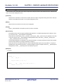
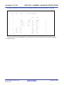
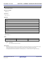
User's Manual
CubeSuite+ V1.01.00
Integrated Development Environment
User's Manual: 78K0 Coding
Target Device
78K0 Microcontroller
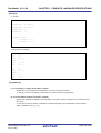
All information contained in these matenals, including products and product specifications,
represents information on the product at the time of publication and is subject to change by
Renesas Electronics Corp. without notice. Please review the latest information published by
Renesas Electronics Corp. through various means, including the Renesas Electronics Corp.
website (http://www.renesas.com).
www.renesas.com
Rev.1.00
Oct 2011
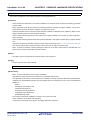
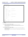
Notice
1.
2.
3.
4.
5.
6.
7.
All information included in this document is current as of the date this document is issued. Such information, however, is
subject to change without any prior notice. Before purchasing or using any Renesas Electronics products listed herein, please
confirm the latest product information with a Renesas Electronics sales office. Also, please pay regular and careful attention to
additional and different information to be disclosed by Renesas Electronics such as that disclosed through our website.
Renesas Electronics does not assume any liability for infringement of patents, copyrights, or other intellectual property rights
of third parties by or arising from the use of Renesas Electronics products or technical information described in this document.
No license, express, implied or otherwise, is granted hereby under any patents, copyrights or other intellectual property rights
of Renesas Electronics or others.
You should not alter, modify, copy, or otherwise misappropriate any Renesas Electronics product, whether in whole or in part.
Descriptions of circuits, software and other related information in this document are provided only to illustrate the operation of
semiconductor products and application examples. You are fully responsible for the incorporation of these circuits, software,
and information in the design of your equipment. Renesas Electronics assumes no responsibility for any losses incurred by
you or third parties arising from the use of these circuits, software, or information.
When exporting the products or technology described in this document, you should comply with the applicable export control
laws and regulations and follow the procedures required by such laws and regulations. You should not use Renesas
Electronics products or the technology described in this document for any purpose relating to military applications or use by
the military, including but not limited to the development of weapons of mass destruction. Renesas Electronics products and
technology may not be used for or incorporated into any products or systems whose manufacture, use, or sale is prohibited
under any applicable domestic or foreign laws or regulations.
Renesas Electronics has used reasonable care in preparing the information included in this document, but Renesas Electronics
does not warrant that such information is error free. Renesas Electronics assumes no liability whatsoever for any damages
incurred by you resulting from errors in or omissions from the information included herein.
Renesas Electronics products are classified according to the following three quality grades: “Standard”, “High Quality”, and
“Specific”. The recommended applications for each Renesas Electronics product depends on the product’s quality grade, as
indicated below. You must check the quality grade of each Renesas Electronics product before using it in a particular
application. You may not use any Renesas Electronics product for any application categorized as “Specific” without the prior
written consent of Renesas Electronics. Further, you may not use any Renesas Electronics product for any application for
which it is not intended without the prior written consent of Renesas Electronics. Renesas Electronics shall not be in any way
liable for any damages or losses incurred by you or third parties arising from the use of any Renesas Electronics product for an
application categorized as “Specific” or for which the product is not intended where you have failed to obtain the prior written
consent of Renesas Electronics. The quality grade of each Renesas Electronics product is “Standard” unless otherwise
expressly specified in a Renesas Electronics data sheets or data books, etc.
“Standard”:
8.
9.
10.
11.
12.
Computers; office equipment; communications equipment; test and measurement equipment; audio and visual
equipment; home electronic appliances; machine tools; personal electronic equipment; and industrial robots.
“High Quality”: Transportation equipment (automobiles, trains, ships, etc.); traffic control systems; anti-disaster systems; anticrime systems; safety equipment; and medical equipment not specifically designed for life support.
“Specific”:
Aircraft; aerospace equipment; submersible repeaters; nuclear reactor control systems; medical equipment or
systems for life support (e.g. artificial life support devices or systems), surgical implantations, or healthcare
intervention (e.g. excision, etc.), and any other applications or purposes that pose a direct threat to human life.
You should use the Renesas Electronics products described in this document within the range specified by Renesas Electronics,
especially with respect to the maximum rating, operating supply voltage range, movement power voltage range, heat radiation
characteristics, installation and other product characteristics. Renesas Electronics shall have no liability for malfunctions or
damages arising out of the use of Renesas Electronics products beyond such specified ranges.
Although Renesas Electronics endeavors to improve the quality and reliability of its products, semiconductor products have
specific characteristics such as the occurrence of failure at a certain rate and malfunctions under certain use conditions. Further,
Renesas Electronics products are not subject to radiation resistance design. Please be sure to implement safety measures to
guard them against the possibility of physical injury, and injury or damage caused by fire in the event of the failure of a
Renesas Electronics product, such as safety design for hardware and software including but not limited to redundancy, fire
control and malfunction prevention, appropriate treatment for aging degradation or any other appropriate measures. Because
the evaluation of microcomputer software alone is very difficult, please evaluate the safety of the final products or system
manufactured by you.
Please contact a Renesas Electronics sales office for details as to environmental matters such as the environmental
compatibility of each Renesas Electronics product. Please use Renesas Electronics products in compliance with all applicable
laws and regulations that regulate the inclusion or use of controlled substances, including without limitation, the EU RoHS
Directive. Renesas Electronics assumes no liability for damages or losses occurring as a result of your noncompliance with
applicable laws and regulations.
This document may not be reproduced or duplicated, in any form, in whole or in part, without prior written consent of Renesas
Electronics.
Please contact a Renesas Electronics sales office if you have any questions regarding the information contained in this
document or Renesas Electronics products, or if you have any other inquiries.
(Note 1) “Renesas Electronics” as used in this document means Renesas Electronics Corporation and also includes its majorityowned subsidiaries.
(Note 2) “Renesas Electronics product(s)” means any product developed or manufactured by or for Renesas Electronics.
How to Use This Manual
This manual describes the role of the CubeSuite+ integrated development environment for developing applications and
systems for 78K0 microcontrollers, and provides an outline of its features.
CubeSuite+ is an integrated development environment (IDE) for 78K0 microcontrollers, integrating the necessary tools
for the development phase of software (e.g. design, implementation, and debugging) into a single platform.
By providing an integrated environment, it is possible to perform all development using just this product, without the
need to use many different tools separately.
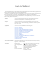
Readers
This manual is intended for users who wish to understand the functions of the
CubeSuite+ and design software and hardware application systems.
Purpose
This manual is intended to give users an understanding of the functions of the
CubeSuite+ to use for reference in developing the hardware or software of systems
using these devices.
Organization
This manual can be broadly divided into the following units.
CHAPTER 1 GENERAL
CHAPTER 2 FUNCTIONS
CHAPTER 3 COMPILER LANGUAGE SPECIFICATIONS
CHAPTER 4 ASSEMBLY LANGUAGE SPECIFICATIONS
CHAPTER 5 LINK DIRECTIVE SPECIFICATIONS
CHAPTER 6 FUNCTION SPECIFICATIONS
CHAPTER 7 STARTUP
CHAPTER 8 ROMIZATION
CHAPTER 9 REFERENCING COMPILER AND ASSEMBLER
CHAPTER 10 CAUTIONS
APPENDIX A WINDOW REFERENCE
APPENDIX B INDEX
How to Read This Manual
It is assumed that the readers of this manual have general knowledge of electricity,
logic circuits, and microcontrollers.
Conventions
Data significance:
Higher digits on the left and lower digits on the right
Active low representation:
XXX (overscore over pin or signal name)
Note:
Footnote for item marked with Note in the text
Caution:
Information requiring particular attention
Remark:
Supplementary information
Numeric representation:
Decimal ... XXXX
Hexadecimal ... 0xXXXX
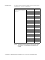
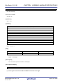
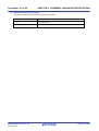
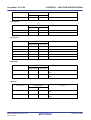
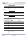
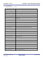
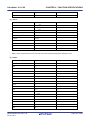
Related Documents
The related documents indicated in this publication may include preliminary versions.
However, preliminary versions are not marked as such.
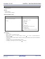
Document Name
CubeSuite+
Integrated Development Environment
Document No.
Start
R20UT0727E
V850 Design
R20UT0549E
R8C Design
R20UT0550E
RL78 Design
R20UT0728E
78K0R Design
R20UT0547E
78K0 Design
R20UT0546E
RX Coding
R20UT0767E
V850 Coding
R20UT0553E
Coding for CX Compiler
R20UT0825E
R8C Coding
R20UT0576E
RL78, 78K0R Coding
R20UT0729E
78K0 Coding
This manual
RX Build
R20UT0768E
V850 Build
R20UT0557E
Build for CX Compiler
R20UT0826E
R8C Build
R20UT0575E
RL78, 78K0R Build
R20UT0730E
78K0 Build
R20UT0783E
RX Debug
R20UT0769E
V850 Debug
R20UT0734E
R8C Debug
R20UT0770E
RL78 Debug
R20UT0733E
78K0R Debug
R20UT0732E
78K0 Debug
R20UT0731E
Analysis
R20UT0735E
Message
R20UT0736E
User's Manual
Caution
The related documents listed above are subject to change without
notice. Be sure to use the latest edition of each document when
designing.
All trademarks or registered trademarks in this document are the property of their respective owners.
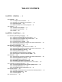
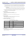
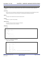
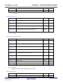
TABLE OF CONTENTS
CHAPTER 1 GENERAL ... 10
1.1 Overview ... 10
1.1.1 C compiler and assembler ... 10
1.1.2 Position of C compiler and assembler ... 13
1.1.3 Processing flow ... 14
1.1.4 Basic structure of C source program ... 15
1.2 Features ... 17
1.2.1 Features of C compiler ... 17
1.2.2 Features of assembler ... 18
1.2.3 Limits ... 18
CHAPTER 2 FUNCTIONS ... 21
2.1 Variables (Assembly Language) ... 21
2.1.1 Defining variables with no initial values ... 21
2.1.2 Defining const constants with initial values ... 21
2.1.3 Defining 1-bit variables ... 21
2.1.4 1/8 bit access of variable ... 22
2.1.5 Allocating to sections accessible with short instructions ... 23
2.1.6 Specifying option bytes ... 23
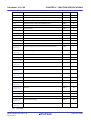
2.2 Variables (C Language) ... 24
2.2.1 Allocating data only of reference in ROM ... 24
2.2.2 Allocating to sections accessible with short instructions ... 24
2.2.3 Allocating addresses directly ... 25
2.2.4 Defining 1-bit variables ... 26
2.2.5 Empty area of the structure is stuffed ... 26
2.2.6 Data location in internal extended RAM ... 27
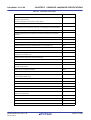
2.3 Functions ... 28
2.3.1 Allocating to sections accessible with short instructions ... 28
2.3.2 Allocating addresses directly ... 28
2.3.3 Inline expansion of function ... 29
2.3.4 Embedding assembly instructions ... 29
2.3.5 norec functions and noauto functions is described ... 30
2.4 Using Microcontroller Functions ... 31
2.4.1 Accessing special function registers (SFR) from C ... 31
2.4.2 Interrupt functions in C ... 32
2.4.3 Using CPU control instructions in C ... 33
2.5 Startup Routine ... 35
2.5.1 Deleting unused functions and areas from startup routine ... 35
2.5.2 Allocating stack area ... 36
2.5.3 Initializing RAM ... 37
2.6 Link Directives ... 38
2.6.1 Partitioning default areas ... 38
2.6.2 Specifying section allocation ... 38
2.7 Reducing Code Size ... 39
2.7.1 Using extended functions to generate efficient object code ... 39
2.7.2 Calculating complex expressions ... 43
2.8 Compiler and Assembler Mutual References ... 44
2.8.1 Mutually referencing variables ... 44
2.8.2 Mutually referencing functions ... 46
2.8.3 When the assembler calls functions written in C, registers must be saved ... 48
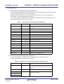
CHAPTER 3 COMPILER LANGUAGE SPECIFICATIONS ... 49
3.1 Basic Language Specifications ... 49
3.1.1 Processing system dependent items ... 49
3.1.2 Internal representation and value area of data ... 59
3.1.3 Memory ... 64
3.2 Extended Language Specifications ... 65
3.2.1 Macro names ... 65
3.2.2 Keywords ... 66
3.2.3 #pragma directives ... 67
3.2.4 Using extended functions ... 68
3.2.5 C source modifications ... 220
3.3 Function Call Interface ... 221
3.3.1 Return values ... 221
3.3.2 Ordinary function call interface ... 221
3.3.3 noauto function call interface (only for normal model) ... 227
3.3.4 norec function call interface (only for normal model) ... 229
3.3.5 Static model function call interface ... 231
3.3.6 Pascal function call interface ... 235
3.4 List of saddr Area Labels ... 238
3.4.1 Normal model ... 238
3.4.2 Static model ... 239
3.5 List of Segment Names ... 240
3.5.1 List of segment names ... 241
3.5.2 Segment allocation ... 242
3.5.3 Example of C source ... 242
3.5.4 Example of output assembler module ... 243
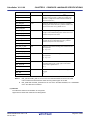
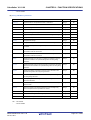
CHAPTER 4 ASSEMBLY LANGUAGE SPECIFICATIONS ... 247
4.1 Description Methods of Source Program ... 247
4.1.1 Basic configuration ... 247
4.1.2 Description method ... 253
4.1.3 Expressions and operators ... 264
4.1.4 Arithmetic operators ... 267
4.1.5 Logic operators ... 275
4.1.6 Relational operators ... 280
4.1.7 Shift operators ... 287
4.1.8 Byte separation operators ... 290
4.2
4.3
4.4
4.5
4.6
4.1.9 Special operators ... 293
4.1.10 Other operator ... 298
4.1.11 Restrictions on operations ... 300
4.1.12 Absolute expression definitions ... 304
4.1.13 Bit position specifier ... 304
4.1.14 Identifiers ... 306
4.1.15 Operand characteristics ... 307
Directives ... 310
4.2.1 Overview ... 311
4.2.2 Segment definition directives ... 312
4.2.3 Symbol definition directives ... 328
4.2.4 Memory initialization, area reservation directives ... 335
4.2.5 Linkage directives ... 343
4.2.6 Object module name declaration directive ... 350
4.2.7 Branch instruction automatic selection directives ... 352
4.2.8 Macro directives ... 355
4.2.9 Assemble termination directive ... 370
Control Instructions ... 372
4.3.1 Overview ... 372
4.3.2 Assemble target type specification control instruction ... 373
4.3.3 Debug information output control instructions ... 375
4.3.4 Cross-reference list output specification control instructions ... 380
4.3.5 Include control instruction ... 385
4.3.6 Assembly list control instructions ... 389
4.3.7 Conditional assembly control instructions ... 412
4.3.8 Kanji code control instruction ... 438
4.3.9 Other control instructions ... 440
Macros ... 441
4.4.1 Overview ... 441
4.4.2 Using macros ... 441
4.4.3 Symbols in macros ... 444
4.4.4 Macro operators ... 445
Reserved Words ... 447
Instructions ... 448
4.6.1 Memory space ... 448
4.6.2 Registers ... 449
4.6.3 Addressing ... 454
4.6.4 Instruction set ... 461
4.6.5 Explanation of instructions ... 467
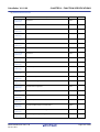
CHAPTER 5 LINK DIRECTIVE SPECIFICATIONS ... 559
5.1 Coding Method ... 559
5.1.1 Link directives ... 559
5.2 Reserved Words ... 564
5.3 Coding Examples ... 564
5.3.1 When specifying link directive ... 564
5.3.2 When using the compiler ... 565
CHAPTER 6 FUNCTION SPECIFICATIONS ... 567
6.1 Distribution Libraries ... 567
6.1.1 Standard library ... 568
6.1.2 Runtime library ... 574
6.2 Interface Between Functions ... 584
6.2.1 Arguments ... 584
6.2.2 Return values ... 584
6.2.3 Saving registers used by separate libraries ... 584
6.2.4 Bank area restrictions ... 588
6.3 Header Files ... 589
6.3.1 ctype.h ... 589
6.3.2 setjmp.h ... 590
6.3.3 stdarg.h (normal model only) ... 591
6.3.4 stdio.h ... 591
6.3.5 stdlib.h ... 592
6.3.6 string.h ... 594
6.3.7 error.h ... 595
6.3.8 errno.h ... 595
6.3.9 limits.h ... 595
6.3.10 stddef.h ... 596
6.3.11 math.h (normal model only) ... 597
6.3.12 float.h ... 599
6.3.13 assert.h (normal model only) ... 601
6.4 Re-entrant (Normal Model Only) ... 601
6.5 Character/String Functions ... 603
6.6 Program Control Functions ... 623
6.7 Special Functions ... 626
6.8 Input and Output Functions ... 631
6.9 Utility Functions ... 648
6.10 String and Memory Functions ... 680
6.11 Mathematical Functions ... 703
6.12 Diagnostic Function ... 750
6.13 Library Stack Consumption List ... 752
6.13.1 Standard libraries ... 752
6.13.2 Runtime libraries ... 756
6.14 List of Maximum Interrupt Disabled Times for Libraries ... 764
6.15 Batch Files for Update of Startup Routine and Library Functions ... 765
6.15.1 Using batch files ... 766
CHAPTER 7 STARTUP ... 769
7.1 Function Overview ... 769
7.2 File Organization ... 769
7.2.1 "bat" folder contents ... 770
7.2.2 "lib" folder contents ... 770
7.2.3 "src" folder contents ... 772
7.3 Batch File Description ... 773
7.3.1 Batch files for creating startup routines ... 773
7.4 Startup Routines ... 774
7.4.1 Overview of startup routines ... 774
7.4.2 Startup routine preprocessing ... 776
7.4.3 Startup routine initial settings ... 778
7.4.4 Startup routine main function startup and postprocessing ... 781
7.5 ROMization Processing in Startup Routine for Flash Area ... 782
7.6 Coding Examples ... 783
7.6.1 When revising startup routine ... 783
CHAPTER 8 ROMIZATION ... 785
CHAPTER 9 REFERENCING COMPILER AND ASSEMBLER ... 786
9.1 Accessing Arguments and Automatic Variables ... 786
9.1.1 Normal model ... 786
9.1.2 Static model ... 789
9.2 Storing Return Values ... 791
9.3 Calling Assembly Language Routines from C Language ... 791
9.3.1 Function information file modifications ... 791
9.3.2 C language function calling procedure ... 792
9.3.3 Saving data from assembly language routine and returning ... 793
9.4 Calling C Language Routines from Assembly Language ... 795
9.4.1 Calling C language function from assembly language program ... 795
9.5 Referencing Variables Defined in C Language ... 799
9.6 Referencing Variables Definted in Assembly Language from C Language ... 800
9.7 Points of Caution for Calling Between C Language Functions and Assembler Functions ... 800
CHAPTER 10 CAUTIONS ... 802
APPENDIX A WINDOW REFERENCE ... 810
A.1 Description ... 810
APPENDIX B INDEX ... 825
CubeSuite+ V1.01.00
CHAPTER 1 GENERAL
CHAPTER 1 GENERAL
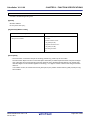
This chapter explains the roles of the 78K0 C compiler package (called "CA78K0") in system development, and provides an outline of their functions.
1.1
Overview
78K0 C compiler is a translation program that converts source programs written in traditional C or ANSI C into machine
language. 78K0 C compiler can produce either object files or assembly source files.
78K0 assembler is a language processing program that converts source programs written in assembly language into
machine language.
1.1.1
C compiler and assembler
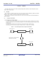
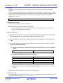
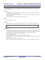
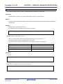
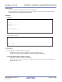
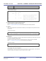
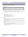
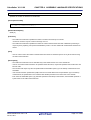
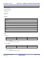
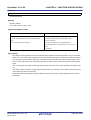
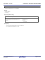
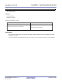
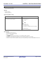
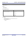
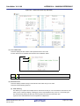
(1) C language and assembly language
A C compiler takes C source modules as input and produces either object modules or assembly source modules
as output. This means that you can develop your programs in C and use assembly language as required to make
fine adjustments.
An assembler takes assembly source modules as input and produces object modules as output.
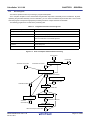
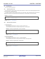
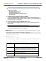
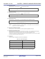
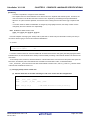
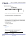
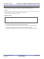
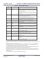
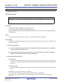
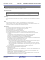
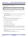
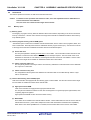
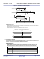
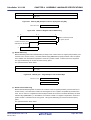
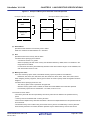
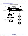
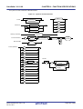
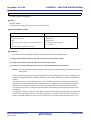
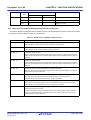
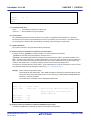
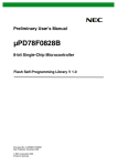
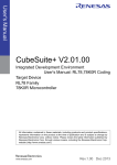
The following figure shows the flow of program development with a C compiler and an assembler.
Figure 1-1. Flow of Development with C Compiler and Assembler
Binary program
Program written in C
Translation program
(C compiler)
(C source modules)
(Object modules)
Program written in assembly language
(assembler source modules)
Binary program
Translation program
(Assembler)
R20UT0782EJ0100 Rev.1.00
Oct 01, 2011
(Object modules)
Page 10 of 836
CubeSuite+ V1.01.00
CHAPTER 1 GENERAL
(2) Relocatable assemblers
The machine language translated from assembly source files by the assembler is written to the memory of the
microcontroller before use. To do this, the location in memory where each machine language instruction is to be
written must already be determined.
Therefore, information is added to the machine language assembled by the assembler, stating where in memory
each machine language instruction is to be located.
Depending on the method used to allocate machine language instructions to memory addresses, assemblers can
be broadly divided into absolute assemblers and relocatable assemblers. RA78K0 is a relocatable assembler.
- Absolute assembler
An absolute assembler allocates machine language instructions assembled from the assembly language at
absolute addresses.
- Relocatable assembler
In a relocatable assembler, the addresses determined for the machine language instructions assembled from
the assembly language are tentative
Absolute addresses are determined subsequently by the linker.
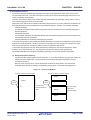
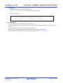
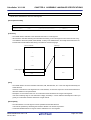
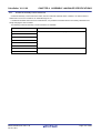
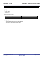
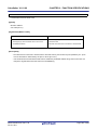
In the past, when programs were created with absolute assemblers, programmers normally had to write the entire
program as a single large block. However, when all the components of a large program are contained in a single
block, the program becomes complicated, making it harder to understand and maintain.
To avoid this, large programs are now usually developed by dividing them into several subprograms, called
modules, one for each functional unit. This programming technique is called modular programming.
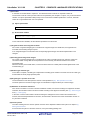
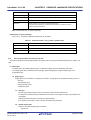
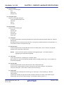
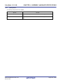
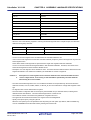
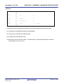
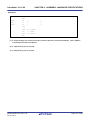
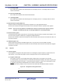
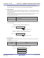
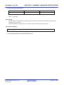
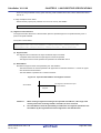
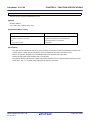
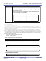
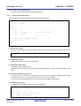
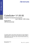
Relocatable assemblers are well suited for modular programming, which has the following advantages:
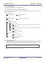
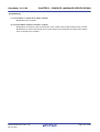
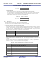
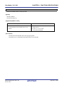
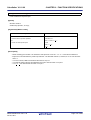
(a) Greater development efficiency
It is difficult to write a large program all at the same time. In such cases, dividing the program into modules for
individual functions enables two or more programmers to develop subprograms in parallel to increase
development efficiency.
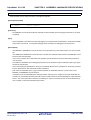
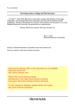
Moreover, when bugs are found, only the module that contained the bugs needs to be corrected and
assembled again, instead of needing to assemble the entire program. This shortens debugging time.
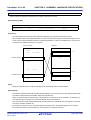
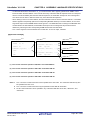
Figure 1-2. Division into Modules
Program consisting of single module
Program consisting of multiple modules
Module
Bug
Module
Bug
Module
found!
found!
Entire program
xxx
must be assembled
again
Only this module
xxx
Module
needs to be
assembled again
Module
R20UT0782EJ0100 Rev.1.00
Oct 01, 2011
Page 11 of 836
CubeSuite+ V1.01.00
CHAPTER 1 GENERAL
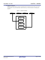
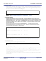
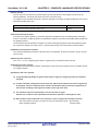
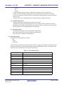
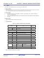
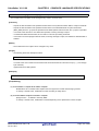
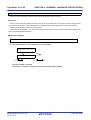
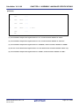
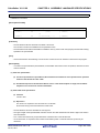
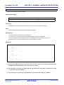
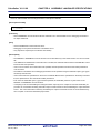
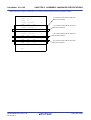
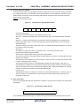
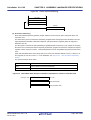
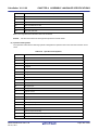
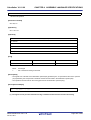
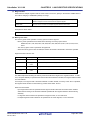
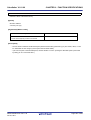
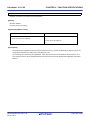
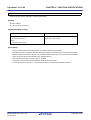
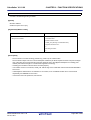
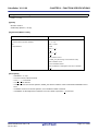
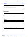
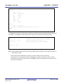
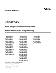
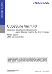
(b) Utilization of resources
Reliable and versatile modules from previous development efforts are software resources that can be reused
in new programs. As you accumulate more of these resources, you save time and labor in developing new
programs.
Figure 1-3. Resource Utilization
Module A
Module B
Module
C C
Module D
New
Module
Module A
New
Module
Module D
New program
R20UT0782EJ0100 Rev.1.00
Oct 01, 2011
Page 12 of 836
CubeSuite+ V1.01.00
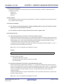
1.1.2
CHAPTER 1 GENERAL
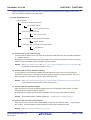
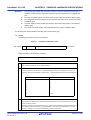
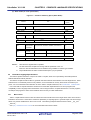
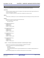
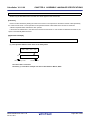
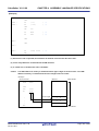
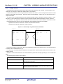
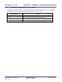
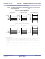
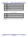
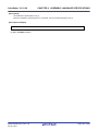
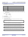
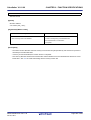
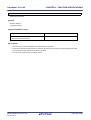
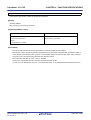
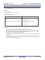
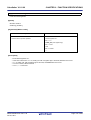
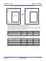
Position of C compiler and assembler
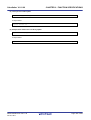
The following figure shows the position of compiler and assembler in the flow of product development.
Figure 1-4. Flow of Microcontroller Application Product Development
Product planning
System design
Hardware development
Software development
Logic design
Software design
Manufacturing
Program coding
Position of
CA78K0
Compilation
and assembly
Testing
NO
NO
OK?
OK?
YES
YES
Debugging
NO
OK?
YES
System evaluation
Marketing
R20UT0782EJ0100 Rev.1.00
Oct 01, 2011
Page 13 of 836
CubeSuite+ V1.01.00
1.1.3
CHAPTER 1 GENERAL
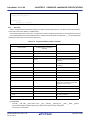
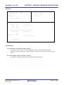
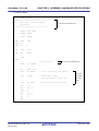
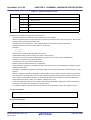
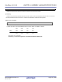
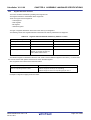
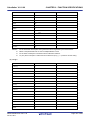
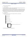
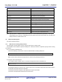
Processing flow
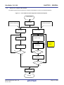
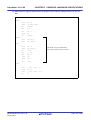
This section explains the flow of processing in program development.
The C compiler compiles C source module files and generates object files or assembly source module files. By hand
optimizing the generated assembly source module files, you can create more efficient object module files. This is useful
when the program must perform high-speed processing and when compact modules are desirable.
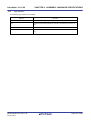
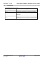
The following programs are involved in the processing flow.
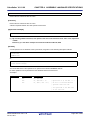
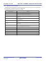
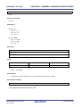
Table 1-1. Programs Involved in Processing Flow
Program
Function
Compiler
Compiles C source module files
Assemble
Assembles assembly language source module files
Linker
Links object module files
Determines addresses of relocatable segments
Object converter
Converts to HEX-format object module files
Librarian
Creates library files
List converter
Generates absolute assemble list files
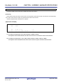
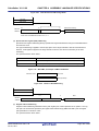
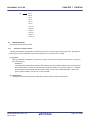
Figure 1-5. Flow of Compiler and Assembler Processing
C source files
Include files
C compiler
Assembler source files
Assembler source files
Assembler
Object module files
Librarian
Library files
Assemble list files
Linker
Load module files
ROMization processor
List converter
ROMization object file
Absolute
assemble list
Object converter
HEX-format object module files
R20UT0782EJ0100 Rev.1.00
Oct 01, 2011
Page 14 of 836
CubeSuite+ V1.01.00
1.1.4
CHAPTER 1 GENERAL
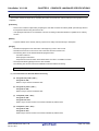
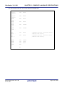
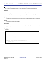
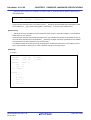
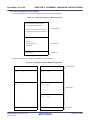
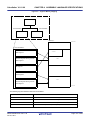
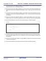
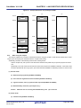
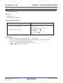
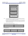
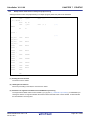
Basic structure of C source program
A program in C is a collection of functions. A function is an independent unit of code that performs a specific action.
Every C language program must have a function "main" which becomes the main routine of the program and is the first
function to be called when execution begins.
Each function consists of a header part, which defines its function name and arguments, and a body part, which
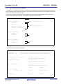
consists of declarations and statements. The format of C programs is shown below.
Definitions of variables/constants
Definitions of data items, variables, and macros
void main ( arguments ) {
Header of the function main
statement 1 ;
statement 2 ;
Body of the function main
function1 ( arguments ) ;
function2 ( arguments ) ;
}
function1 ( arguments ) {
statement 1 ;
function1
statement 2 ;
}
function2 ( arguments ) {
statement 1 ;
function2
statement 2 ;
}
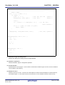
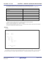
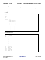
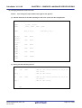
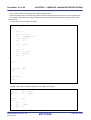
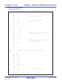
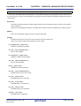
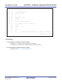
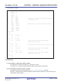
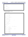
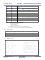
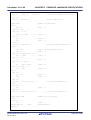
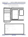
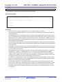
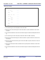
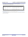
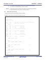
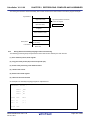
An actual C source program looks like this.
#define TRUE
1
/* #define xxx xxx
Preprocessor directive (macro definition) */
#define FALSE
0
/* #define xxx xxx
Preprocessor directive (macro definition) */
#define SIZE
200
/* #define xxx xxx
Preprocessor directive (macro definition) */
void displaystring ( char*, int );
/* xxx xxxx ( xxx, xxx )
Function prototype declaration */
void displaychar ( char );
/* xxx xxxx ( xxx )
Function prototype declaration */
char
mark[SIZE + 1] ;
/* char xxx
Type declaration, External definition */
/* xx[xx]
Operator */
/* int xxx
Type declaration */
/* xx = xx
Operator */
void main ( void ) {
int
i, prime, k, count ;
count = 0 ;
R20UT0782EJ0100 Rev.1.00
Oct 01, 2011
Page 15 of 836
CubeSuite+ V1.01.00
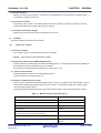
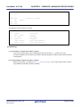
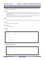
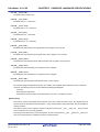
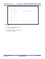
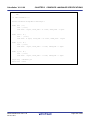
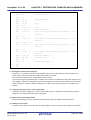
for ( i = 0 ; i <= SIZE ; i ++ )
CHAPTER 1 GENERAL
/* for ( xx ; xx ; xx ) xxx ; Control
structure */
mark[i] = TRUE ;
for ( i = 0 ; i <= SIZE ; i ++ ) {
if ( mark[i] ) {
prime = i + i + 3 ;
/* xxx = xxx + xxx + xxx
Operator */
displaystring ( "%6d", prime );
/* xxx ( xxx );
Operator */
count ++ ;
if ( ( count%8 ) == 0 ) displaychar ( '\n' );
/* if ( xxx ) xxx ;
Control structure */
for ( k = i + prime ; k <= SIZE ; k += prime )
mark[k] = FALSE ;
}
}
displaystring ( "\n%d primes found.", count );
/* xxx ( xxx ); Operator */
}
void displaystring ( char *s, int i ) {
int
j ;
char
*ss ;
j = i ;
ss = s ;
}
void displaychar ( char c ) {
char
d ;
d = c ;
}
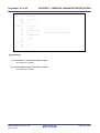
(1) Declaration of type and storage class
Declares the data type and storage class of an object identifier.
(2) Operator or expression
Performs arithmetic, logical, or assignment operations.
(3) Control structure
Specifies the flow of the program. C has a number of instructions for different types of control, such as conditional
control, iteration, and branching.
(4) Structure or union
Declares a structure or union. A structure is a data object that contains several subobjects or members that may
have different types. A union is like a structure, but allows two or more variables to share the same memory.
R20UT0782EJ0100 Rev.1.00
Oct 01, 2011
Page 16 of 836
CubeSuite+ V1.01.00
CHAPTER 1 GENERAL
(5) External definition
Declares a function or external object. A function is an independent unit of code that performs a specific action. A
C program is a collection of functions.
(6) Preprocessor directive
An instruction to the compiler. The #define directive instructs the compiler to replace any instances of the first
operand that appear in the program with the second operand.
(7) Declaration of function prototype
Declares the types of the return value and arguments of a function.
1.2
Features
This section explains the features of the CA78K0.
1.2.1
Features of C compiler
(1) Conforms to ANSI C
The compiler conforms to the ANSI standard for the C language.
Remark
ANSI: American National Standards Institute
(2) Designed for efficient use of ROM and RAM memory
External variables can be allocated to short direct addressing memory. Function arguments and auto variables can
be allocated to short direct addressing memory or registers.
Bit instructions enable definitions and operations on data in units of 1 bit.
(3) Interrupt control features
Peripheral hardware of 78K0 can be controlled directly from C.
Interrupt handlers can be written directly in C.
(4) Supports extended functions of 78K0
78K0 C compiler supports the following extended functions, which are not defined in the ANSI standard. Some of
these functions allow special-purpose registers to be accessed in C, while others enable more compact object
code and higher execution speed.
The following table lists extended functions that reduce the size of object code and improve execution speed.
Table 1-2. Methods to Improve Execution Speed
Method
Extended Function
Functions can be called using the callt table area.
callf/__callf functions
Allocate variables to registers
Register variables
Allocate variables to the saddr area
sreg/__sreg
Use sfr names.
sfr area
Functions that do not output code for preprocessing and post-
noauto functions,norec/__leaf functions,
processing (stack frame formation) can be created.
Embed assembly language statements in C source programs.
Accessing the saddr or sfr area can be made on a bit-by-bit basis.
ASM statements
bit type variables, boolean/__boolean type
variables
R20UT0782EJ0100 Rev.1.00
Oct 01, 2011
Page 17 of 836
CubeSuite+ V1.01.00
CHAPTER 1 GENERAL
Method
Extended Function
A function body can be stored in the callf area.
callf/__callff unctions,
Specify bit fields using the unsigned char type.
Bit field declarations
The code to multiply can be directly output with inline expansion.
Multiplication function
The code to divide can be directly output with inline expansion.
Division function
The code to rotate can be directly output with inline expansion.
Rotation functions
Specific addresses in the memory space can be accessed.
Absolute address function
Specific data and instructions can be directly embedded in the code
Data insertion function
area.
The used stack is corrected on the called function side.
__pascal function
memcpy and memset are directly expanded inline and output.
Memory function
See "3.2 Extended Language Specifications" for detailed information about the extended functions of the 78K0 C
compiler.
1.2.2
Features of assembler
The 78K0 assembler has the following features.
(1) Macro function
When the same group of instructions occurs in a source program over and over again, you can define a macro to
give a single name to the group of instructions.
Macros can increase your coding efficiency and make your programs more readable.
The 78K0 assembler provides the BR (Branch instruction automatic selection directives).
A characteristic of programs that make efficient use of memory is selection of the appropriate branching
instructions, using only the number of bytes required by the branch destination range. But it is a burden for the
programmer to need to be conscious of the branch destination range for every branch. The BR directives are
automatic solutions to this problem. They facilitate memory-efficient branching by instructing the assembler to
generate the most appropriate branching instruction for the branch destination range. This function is called
branch instruction optimization.
(2) Conditional assembly
Conditional assembly allows you to specify conditions that determine whether or not specific sections of the source
program are assembled.
For example, when the source contains debugging statements, a switch can be set to determine whether or not
they should be translated into machine language. When they are no longer needed, they can be excluded from the
output with no major modifications to the source program.
1.2.3
Limits
(1) Compiler limits
See "(9) Translation Limit" for the limits of the compiler.
R20UT0782EJ0100 Rev.1.00
Oct 01, 2011
Page 18 of 836
CubeSuite+ V1.01.00
CHAPTER 1 GENERAL
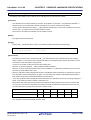
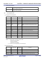
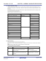
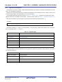
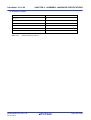
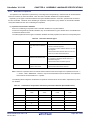
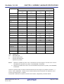
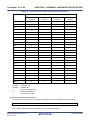
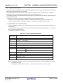
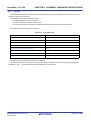
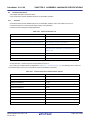
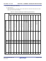
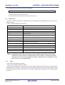
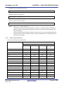
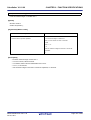
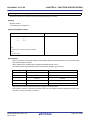
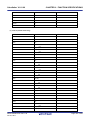
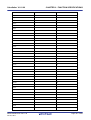
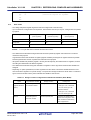
(2) Assembler limits
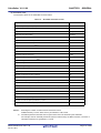
The maximum values for the assembler are shown below.
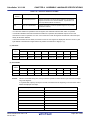
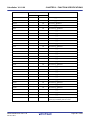
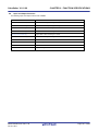
Table 1-3. Assembler Translation Limits
Description
Limit
Number of symbols (local + public)
65,535
Number of symbols for which cross-reference list can be output
65,534Note 1
Maximum size of macro body for one macro reference
1 Mbyte
Total size of all macro bodies
10 Mbyte
Number of segments in one file
256
Number of macro and include specifications in one file
10,000
Number of macro and include specifications in one include file
10,000
Number of relocation data items Note 2
65,535
Line number data items
65,535
Number of BR directives in one file
32,767
Character length of source line
2,048Note 3
Character length of symbol
256
Character length of name definition Note 4
1,000
Character length of switch name Note 4
31
Character length of segment name
8
Character length of module name (NAME directive)
256
Number of parameters in MACRO directive
16
Number of arguments in macro reference
16
Number of arguments in IRP directive
16
Number of local symbols in macro body
64
Total number of local symbols in expanded macro
65,535
Nesting levels in macro (macro reference, REPT directive, IRP directive)
8 levels
Number of characters in TITLE control instruction (-lh option)
60Note 5
Number of characters in SUBTITLE control instruction
72
Include file nesting levels in 1 file
16 levels
Conditional assembly nesting levels
8 levels
Number of include file paths specifiable by -i option
64
Number of symbols definable by -d option
30
Notes 1.
Excluding the number of module names and section names.
Available memory is used. When memory is insufficient, a file is used.
2.
Information passed to the linker when a symbol value cannot be resolved by the assembler.
For example, when an externally referenced symbol is referenced by the MOV instruction, two items of
relocation information are generated in a .rel file.
R20UT0782EJ0100 Rev.1.00
Oct 01, 2011
Page 19 of 836
CubeSuite+ V1.01.00
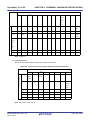
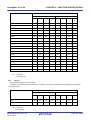
3.
CHAPTER 1 GENERAL
Including CR and LF codes. If a line is longer than 2048 characters, a warning message is output and
the 2049th and following characters are ignored.
4.
Switch names are set to true/false by the SET and RESET directives and are used by constructs such
as $If.
5.
If the maximum number of characters that can be specified in one line of the assemble list file ("X") is
119, this figure will be "X - 60" or less.
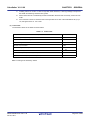
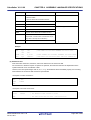
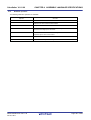
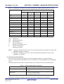
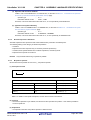
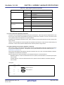
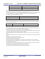
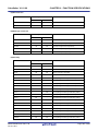
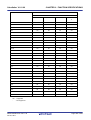
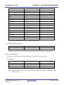
(3) Linker limits
The maximum values for the linker are shown below.
Table 1-4. Linker Limits
Description
Limit
Number of symbols (local + public)
65,535
Line number data items in 1 segment
65,535
Number of segments
65,535
Number of input modules
1,024
Character length of memory area name
256
Number of memory areas
100Note
Number of library files specifiable by the -b option
64
Number of include file paths specifiable by the -i option
64
Note Including those defined by default.
R20UT0782EJ0100 Rev.1.00
Oct 01, 2011
Page 20 of 836
CubeSuite+ V1.01.00
CHAPTER 2 FUNCTIONS
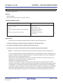
CHAPTER 2 FUNCTIONS
This chapter explains programming technique to use CA78K0 more effectively and use of extended functions.
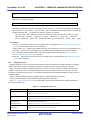
2.1
Variables (Assembly Language)
This section explains techniques for using variables in assembly language.
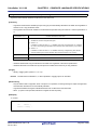
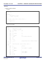
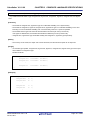
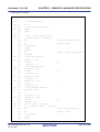
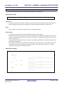
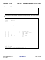
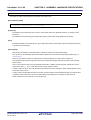
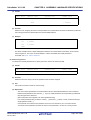
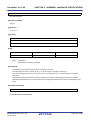
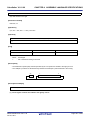
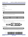
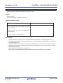
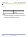
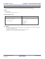
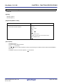
2.1.1
Defining variables with no initial values
Allocate memory area in a data segment.
Use the DSEG quasi directive to define a data segment, and use the DS quasi directive to allocate memory area.
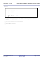
Example Define an 10-byte variable with no initial values.
DSEG
_table :
Remark
2.1.2
DS
10
See "DSEG" and "DS".
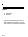
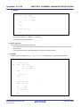
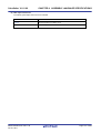
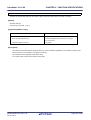
Defining const constants with initial values
Initialize memory area in a code segment.
Use the CSEG quasi directive to define a code segment, and use the DB (1 byte), or DW (2 bytes) quasi directive to
initialize memory area.
Example Defining constants with initial values
CSEG
_val1 :
DB
0F0H
; 1 byte
_val2 :
DW
1234H
; 2 bytes
Remark
2.1.3
See "CSEG", "DB", and "DW".
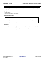
Defining 1-bit variables
Allocate 1 bit memory area in a bit segment.
Use the BSEG quasi directive to define a bit segment, and use the DBIT quasi directive to allocate 1 bit memory area.
Example Define bit variables with no initial values.
BSEG
_bit1
DBIT
_bit2
DBIT
_bit3
DBIT
Remark
See "BSEG" and "DBIT".
R20UT0782EJ0100 Rev.1.00
Oct 01, 2011
Page 21 of 836
CubeSuite+ V1.01.00
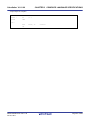
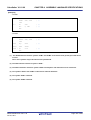
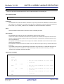
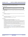
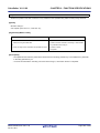
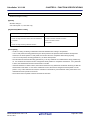
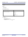
2.1.4
CHAPTER 2 FUNCTIONS
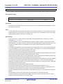
1/8 bit access of variable
In assembly language source code, give two symbols for the address in the saddr area. To use the symbol name
respectively for the bit access and for byte access,specify saddr as the relocation attribute of a DSEG segment, define bit
name of a symbol for byte access as a symbol name for bit access by a EQU quasi directives.
Example Byte access symbol name:
Bit access symbol name:
FLAGBYTE
FLAGBIT
- smp1.asm
NAME
SMP1
PUBLIC
FLAGBYTE, FLAGBIT
FLAGS
DSEG
SADDR
FLAGBYTE :
DS (1)
FLAGBIT
EQU
; The relocation attribute of DSEG is SADDR
; Define FLAGBYTE
FLAGBYTE.0
; Define FLAGBIT
END
- smp2.asm
NAME
SMP2
EXTRN
FLAGBYTE
EXTBIT
FLAGBIT
; FLAGBIT declared as EXTBIT
CSEG
C1 :
MOV
FLAGBYTE, #0FFH
CLR1
FLAGBIT
END
Remark
See "DSEG" and "EQU".
R20UT0782EJ0100 Rev.1.00
Oct 01, 2011
Page 22 of 836
CubeSuite+ V1.01.00
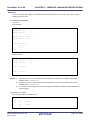
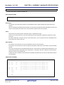
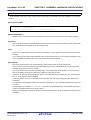
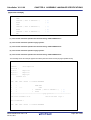
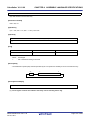
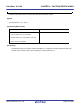
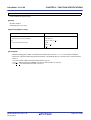
2.1.5
CHAPTER 2 FUNCTIONS
Allocating to sections accessible with short instructions
Compared to other data memory areas, the short direct addressing area can be accessed with shorter instructions.
Improve the memory efficiency of programs by efficiently using this area.
To allocate in the short direct addressing area, specify saddr or saddrp as the relocation attribute of a DSEG quasi
directive.
The following examples explains use in assembly source code.
- Module 1
PUBLIC
TMP1, TMP2
WORK
DSEG saddrp
TMP1 :
DS 2 ; word
TMP2 :
DS 1 ; byte
- Module 2
EXTRN
TMP1, TMP2
SAB
CSEG
MOVW
TMP1, #1234H
MOV
TMP2, #56H
:
Remark
2.1.6
See "DSEG".
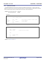
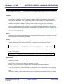
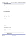
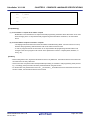
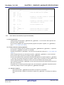
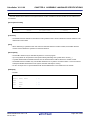
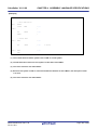
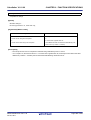
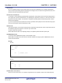
Specifying option bytes
To specify an option byte, add an assembly source module and specify the byte with a DB pseudo instruction.
A simple method is to add it to the startup routine.
Example To set an option byte to 0F1H
OPT
CSEG
OPT_BYTE
OPTION: DB
30H
DB
00H
DB
00H
DB
00H
DB
02H
Remark
See"CSEG" and "DB".
R20UT0782EJ0100 Rev.1.00
Oct 01, 2011
Page 23 of 836
CubeSuite+ V1.01.00
2.2
CHAPTER 2 FUNCTIONS
Variables (C Language)
This section explains Variables (C language).
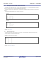
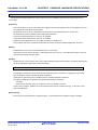
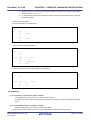
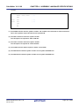
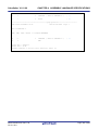
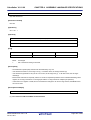
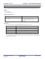
2.2.1
Allocating data only of reference in ROM
(1) Allocating variables with initial values in ROM
Specify the const qualifier to allocate variables with initial values only of a reference in ROM.
Example Allocating variable "a" with initial values only of a reference in ROM
const int
a = 0x12 ;
/* Allocating ROM */
int
b = 0x12 ;
/* Allocating ROM/RAM */
Variable "a" is allocated in ROM.
For variable "b", the initializing value is allocated in ROM and the variable itself is allocated in RAM (areas is
required in both ROM and RAM).
Startup routine ROMization, an initial value of ROM is copied in a variable of RAM.
ROMization requires areas in both ROM and RAM.
(2) Allocating table data in ROM
If allocating table data in ROM only, define type qualifier const, as follows.
const unsigned char
2.2.2
table_data[9] = { 1, 2, 3, 4, 5, 6, 7, 8, 9 } ;
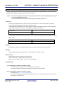
Allocating to sections accessible with short instructions
Compared to other data memory areas, the short direct addressing area can be accessed with shorter instructions.
Improve the memory efficiency of programs by efficiently using this area.
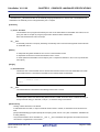
The use example is shown below.
External variables defined sreg or __sreg, and static variables within functions (called sreg variables) are automatically
allocated in relocatable in short direct addressing area [FE20H to FEB3H] (normal model) and [FE20H to FECFH] (Static
Model).
extern sreg int hsmm0 ;
extern sreg int hsmm1 ;
extern sreg int *hsptr ;
void main ( void ) {
hsmm0 -= hsmm1 ;
}
Remark
See "How to use the saddr area (sreg/__sreg)".
R20UT0782EJ0100 Rev.1.00
Oct 01, 2011
Page 24 of 836
CubeSuite+ V1.01.00
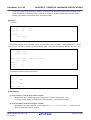
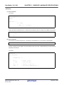
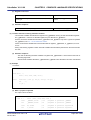
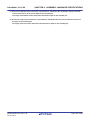
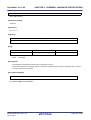
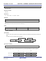
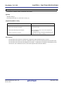
2.2.3
CHAPTER 2 FUNCTIONS
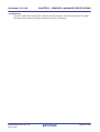
Allocating addresses directly
(1) direcrtmap
External variable declared __directmap and the initializing value of static variable in functions are allocation
address, the variable is mapped to the specified address. Specify the allocation address as an integral number.
__directmap variables in C source files are handled as well as static variables.
Make the __directmap declaration in the module which defines the variable that to map to an absolute address.
__directmap char
c = 0xfe00 ;
__directmap __sreg char d = 0xfe20 ;
__directmap __sreg char e = 0xfe21 ;
__directmap struct x {
char
a ;
char
b ;
} xx = { 0xfe30 } ;
void main ( void ) {
c = 1 ;
d = 0x12 ;
e.5 = 1 ;
xx.a = 5 ;
xx.b = 10 ;
}
Remark
See "Absolute address allocation specification (__directmap)".
(2) Using section names
Change the compiler output section name and specify a starting address.
Use the #pragma directive to specify the name of the section to be changed, a new name, and the starting address
of the new section.
The following example changes the section name from @@CODE to CC1, and specifies 2400H as the starting
address.
#pragma section @@CODE CC1 AT
2400H
void main ( void ) {
/* Function definition */
}
Remark
See "Changing compiler output section name (#pragma section ...)".
R20UT0782EJ0100 Rev.1.00
Oct 01, 2011
Page 25 of 836
CubeSuite+ V1.01.00
2.2.4
CHAPTER 2 FUNCTIONS
Defining 1-bit variables
The variable is made bit and boolean type, are handled as 1-bit data, and are allocated in the short direct addressing
area.
bit and boolean type variables are handled in the same way as external variables with no initial values (irregularity).
The compiler generates the following bit manipulation instructions to this bit variables.
- MOV1, AND1, OR1, XOR1, SET1, CLR1, NOT1, BT, BF
The bit access to the short direct addressing area becomes possible in C source code.
#define ON
1
#define OFF
0
extern bit
data1 ;
extern bit
data2 ;
void main ( void ) {
data1 = ON ;
data2 = OFF ;
while ( data1 ) {
data1 = data2 ;
testb ( ) ;
}
if ( data1 && data2 )
chgb ( ) ;
}
Remark
2.2.5
See "bit type variables (bit), boolean type variables (boolean/__boolean)".
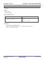
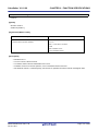
Empty area of the structure is stuffed
Specify the -rc option to deselect alignment of structure members on 2-byte boundaries.
However, there is no support for deselecting alignment of non-structure variables.
R20UT0782EJ0100 Rev.1.00
Oct 01, 2011
Page 26 of 836
CubeSuite+ V1.01.00
2.2.6
CHAPTER 2 FUNCTIONS
Data location in internal extended RAM
To locate data in internal extended RAM using C language, specify the data to locate in the alias section and also
specify the link directive.
Example If you locate the data as follows,
#pragma section @@DATA IXDATA
int i;
/* Data allocated in internal extended RAM */
#pragma section @@DATA @@DATA
int j;
/* Data allocated in High-speed internal RAM */
specify the link directive as follows.
memory IXRAM : ( 0F400H, 400H )
merge
Remark
IXDATA := IXRAM
See "Changing compiler output section name (#pragma section ...)".
R20UT0782EJ0100 Rev.1.00
Oct 01, 2011
Page 27 of 836
CubeSuite+ V1.01.00
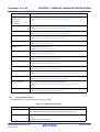
2.3
CHAPTER 2 FUNCTIONS
Functions
This section explains functions.
2.3.1
Allocating to sections accessible with short instructions
Using callt function calls, obtain code that is more compact that the code for normal function calls.
A callt instruction stored the address of the called function in the area [40H - 7FH] called a callt table. And possible to
call the function by a short code than the function is called directly.
__callt void
func1 ( void ) ;
__callt void
func1 ( void ) {
/* Function definition */
}
Remark
2.3.2
See "callt functions (callt/__callt)", "norec functions (norec)" and "callf functions (callf/__callf)".
Allocating addresses directly
(1) Using section names
Change the compiler output section name and specify a starting address.
Use the #pragma directive to specify the name of the section to be changed, a new name, and the starting address
of the new section.
#pragma section @@DATA
??DATA
AT 0DE00H
int
a1 ;
// ??DATA
int
a2 ;
// ??DATA
#pragma section @@DATS
??DATS
AT 0FE30H
sreg int
b1 ;
// ??DATS
sreg int
b2 ;
// ??DATS
Remark
See "Changing compiler output section name (#pragma section ...)".
R20UT0782EJ0100 Rev.1.00
Oct 01, 2011
Page 28 of 836
CubeSuite+ V1.01.00
2.3.3
CHAPTER 2 FUNCTIONS
Inline expansion of function
#pragma inline instructs to generate inline expansion code for memory operation standard library memcpy and memse,
instead of calling functions.
If to make the execution faster by expanding other functions inline, there are no instructions which can be inline
expansive every function. If the function except memcpy and memset being inline-expansive, define a macro in function
format,as shown below.
#define MEMCOPY ( a, b, c ) \
{ \
struct st { unsigned char d[ ( c ) ]; } ; \
* ( ( struct st * ) ( a ) ) = * ( ( struct st * ) ( b ) ) ; \
}
Remark
2.3.4
See "Memory manipulation function (#pragma inline)".
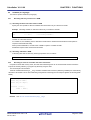
Embedding assembly instructions
Embedding assembly instructions in the assembler source file output by the compiler.
(1) #asm - #endasm
#asm marks the start of an assembly source code block, and #endasm marks its end. Write assembly source code
between the #asm and #endasm.
#asm
:
/* Assembly source */
#endasm
[Output assemble file] by [Compile Options] tab of Property panel, set it as "Yes." (See "CubeSuite+78K0 Build" for
a setting method.)
Remark
See "ASM statements (#asm - #endasm/__asm)".
(2) __asm
Described by the next form in the C source.
__asm ( string literal ) ;
Characters in the string literal are interpreted according to the ANSI conventions. Escape sequences, the line
continues on the next line by '\' character, and concatenate strings can be described.
[Output assemble file] by [Compile Options] tab of Property panel, set it as "Yes." (See "CubeSuite+ 78K0 Build" for
a setting method.)
Remark
See "ASM statements (#asm - #endasm/__asm)".
R20UT0782EJ0100 Rev.1.00
Oct 01, 2011
Page 29 of 836
CubeSuite+ V1.01.00
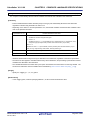
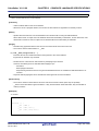
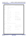
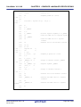
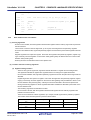
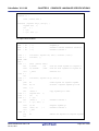
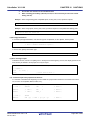
2.3.5
CHAPTER 2 FUNCTIONS
norec functions and noauto functions is described
No pre/post-processing (stack frame) code is generated for norec and noauto functions.
- noauto function
A function can be defined as noauto if the following two conditions are met.
- All the arguments of the function can be assigned to registers according to the rules described in "3.3.3
noauto function call interface (only for normal model)".
- All automatic variables can be assigned to surplus registers and saddr areasNote for register variable after
arguments are assigned.
noauto
short
short
l, m ;
nfunc ( short a, short b, short c );
void main ( ) {
static short ii, jj, kk ;
l = nfunc ( ii, jj, kk );
}
noauto
short
nfunc ( short a, short b, short c ) {
m = a + b + c ;
return ( m );
}
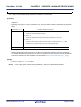
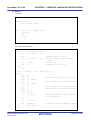
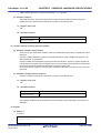
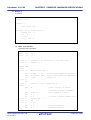
- norec function
A function can be defined as norec if the following three conditions are met.
- The function does not call other functions.
- All the arguments of the function can be assigned to registers and the saddr areasNote according to the rules
described in "3.3.4 norec function call interface (only for normal model)".
- All the automatic variables are assigned to the surplus registers, saddr areasNote for arguments for norec
functions and saddr areasNote for automatic variables for norec functions.
norec int
int
rout ( int
a, int
b, int
c );
i, j ;
void main ( void ) {
int
k, l, m ;
i = l + rout ( k, l, m ) + ++k ;
}
norec int
int
rout ( int a, int b, int c ) {
x, y ;
return ( x + ( a << 2 ) );
}
Note The saddr area is only available when the -qr option is specified.
Remark
See "noauto functions (noauto)" and "norec functions (norec)".
R20UT0782EJ0100 Rev.1.00
Oct 01, 2011
Page 30 of 836
CubeSuite+ V1.01.00
2.4
CHAPTER 2 FUNCTIONS
Using Microcontroller Functions
This section explains using microcontroller functions.
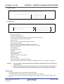
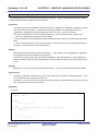
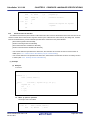
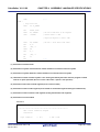
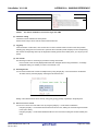
2.4.1
Accessing special function registers (SFR) from C
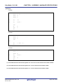
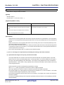
(1) Setting each register of SFR
The SFR area are a area of group of special function registers, such as mode and control registers for the
peripheral hardware of 78K0 microcontrollers (PM1, P1, TMC80, etc.).
To use the SFR area from C, place the #pragma sfr at the start of C source file. This declares the name of each
SFR register. The sfr keyword can be either uppercase or lowercase.
#pragma sfr
The following error message appears if attempt to use the SFR area without declaring the register names.
E0711 Undeclared 'variable-name' ; function 'function-name'
The symbols made available by the #pragma sfr directive are the same as the abbreviations given in the list of
special function registers.
If #pragma PC (processor type) is specified, however, describe #pragma sfr after that.
The following items can be described before #pragma sfr:
- Comments
- Preprocessor directive which does neither define nor see to a variable or a function
In the C source, simply use the sfr names supported by the target device. The sfr names do not need to be
declared individually.
SFR names are external variables with no initial values (irregularity).
A compiler error occurs if assign invalid constant data to an SFR name.
Remark
See "How to use the sfr area (sfr)".
(2) Specifying bits in SFR registers
As shown below, specify bits in SFR registers by using reserved names or by using the "register-name.bitposition".
Examples 1.
Starting TM1
TCE1 = 1 ;
or
TMC1.0 = 1 ;
2.
Stopping TM1
TCE1 = 0 ;
or
TMC1.0 = 0 ;
R20UT0782EJ0100 Rev.1.00
Oct 01, 2011
Page 31 of 836
CubeSuite+ V1.01.00
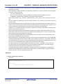
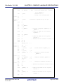
2.4.2
CHAPTER 2 FUNCTIONS
Interrupt functions in C
(1) Interrupt function
The following two directives are provided when the interrupt function is specified.
- #pragma interrupt
- #pragma vect
Either can be used. And the vector table is generated, which can check in the assembler source list output.
Place the #pragma directive at the start of the C source file.
The following items can be described before #pragma directives:
- Comments
- Preprocessor directive which does neither define nor see to a variable or a function
Example Processing for input to INTP0 pin
#pragma interrupt INTP0 inter rb1
void
inter ( void ) {
/* Processing for input to INTP0 pin*/
}
Remark
See "Interrupt functions (#pragma vect/#pragma interrupt)".
(2) Allocating stack area
When using the extended functions for interrupt functions, and do not specify stack switching, the compiler uses
the default stack. It does not allocate any extra stack space that be required.
R20UT0782EJ0100 Rev.1.00
Oct 01, 2011
Page 32 of 836
CubeSuite+ V1.01.00
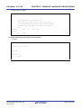
2.4.3
CHAPTER 2 FUNCTIONS
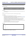
Using CPU control instructions in C
(1) halt instruction
The halt instruction is one of the standby functions of the microcontroller. To use it, use the #pragma HALT as
shown below.
Place the #pragma directive at the start of the C source file.
The following items can be described before #pragma directives:
- Comments
- Preprocessor directive which does neither define nor see to a variable or a function
In the form similar to the function call, describes it by the uppercase letter in C source as follows.
Example Using the halt instruction
#pragma HALT
:
void
func ( void ) {
:
HALT ( ) ;
}
Remark
See "CPU control instruction(#pragma HALT/STOP/BRK/NOP)".
(2) stop instruction
The stop instruction is one of the standby functions of the microcontroller. To use it, use the #pragma STOP as
shown below.
Place the #pragma directive at the start of the C source file.
The following items can be described before #pragma directives:
- Comments
- Preprocessor directive which does neither define nor see to a variable or a function
In the form similar to the function call, describes it by the uppercase letter in C source as follows.
Example Using the stop instruction
#pragma STOP
:
void
func ( void ) {
:
STOP ( ) ;
}
Remark
See "CPU control instruction(#pragma HALT/STOP/BRK/NOP)".
R20UT0782EJ0100 Rev.1.00
Oct 01, 2011
Page 33 of 836
CubeSuite+ V1.01.00
CHAPTER 2 FUNCTIONS
(3) brk instruction
To use software interrupt of a microcontroller, use the #pragma BRK as shown below.
Place the #pragma directive at the start of the C source file.
The following items can be described before #pragma directives:
- Comments
- Preprocessor directive which does neither define nor see to a variable or a function
In the form similar to the function call, describes it by the uppercase letter in C source as follows.
Example Using the brk instruction
#pragma BRK
:
void
func ( void ) {
:
BRK ( ) ;
}
Remark
See "CPU control instruction(#pragma HALT/STOP/BRK/NOP)".
(4) nop instruction
The nop instruction advances the clock without operating a microcontroller. To use it, use the #pragma NOP as
shown below.
Place the #pragma directive at the start of the C source file.
The following items can be described before #pragma directives:
- Comments
- Preprocessor directive which does neither define nor see to a variable or a function
In the form similar to the function call, describes it by the uppercase letter in C source as follows.
Example Using the nop instruction
#pragma NOP
:
void
func ( void ) {
:
NOP ( ) ;
}
Remark
See "CPU control instruction(#pragma HALT/STOP/BRK/NOP)".
R20UT0782EJ0100 Rev.1.00
Oct 01, 2011
Page 34 of 836
CubeSuite+ V1.01.00
2.5
CHAPTER 2 FUNCTIONS
Startup Routine
This section explains startup routine.
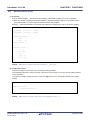
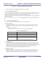
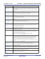
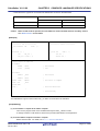
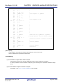
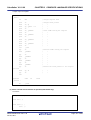
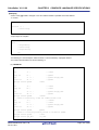
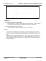
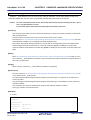
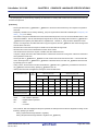
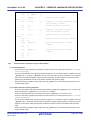
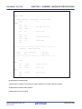
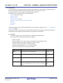
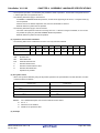
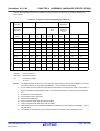
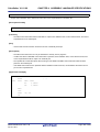
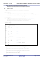
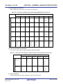
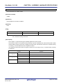
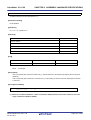
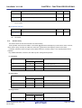
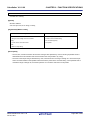
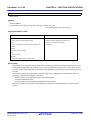
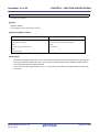
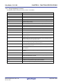
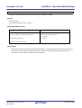
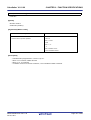
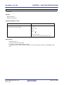
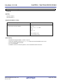
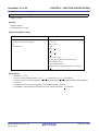
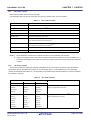
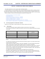
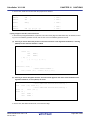
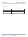
2.5.1
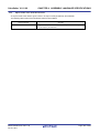
Deleting unused functions and areas from startup routine
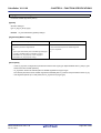
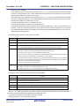
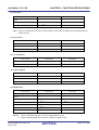
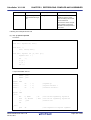
(1) Deleting the exit function
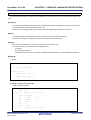
Delete the exit function by setting the EQU symbol EXITSW in the startup routine to 0.
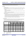
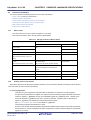
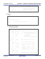
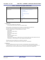
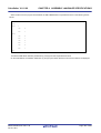
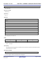
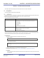
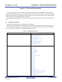
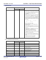
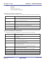
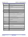
(2) Deleting unused areas
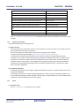
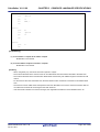
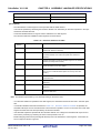
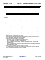
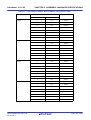
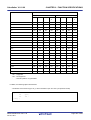
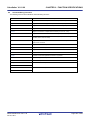
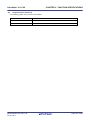
An unused area about the area such as _ @FNCTBL that a standard library uses can be deleted by confirming the
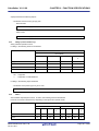
library used, and changing the value of the EQU symbol such as EXITSW in startup routine cstart.asm.
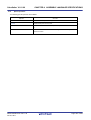
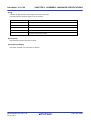
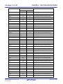
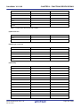
The following table lists the controlling EQU symbols and the affected library function names and symbol names.
EQU Symbol
BRKSW
Library Function Name
Symbol Name
brk
_errno
sbrk
_@MEMTOP
malloc
_@MEMBTM
calloc
_@BRKADR
realloc
free
EXITSW
exit
_@FNCTBL
_@FNCENT
RANDSW
rand
_@SEED
srand
DIVSW
div
_@DIVR
LDIVSW
ldiv
_@LDIVR
STRTOKSW
strtok
_@TOKPTR
FLOATSW
atof
_errno
strtod
Math functions
Floating point runtime library
Remark
See "7.4 Startup Routines".
R20UT0782EJ0100 Rev.1.00
Oct 01, 2011
Page 35 of 836
CubeSuite+ V1.01.00
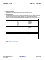
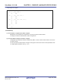
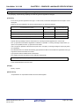
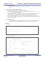
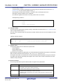
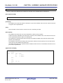
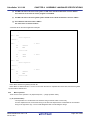
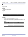
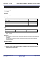
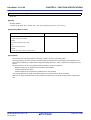
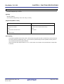
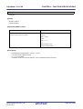
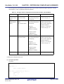
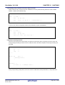
2.5.2
CHAPTER 2 FUNCTIONS
Allocating stack area
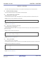
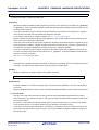
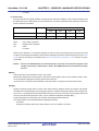
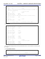
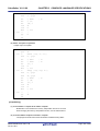
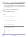
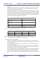
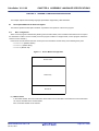
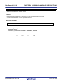
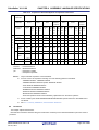
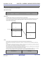
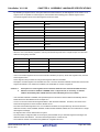
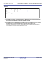
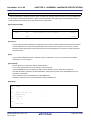
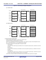
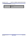
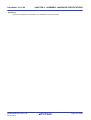
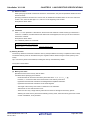
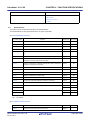
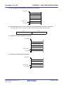
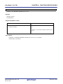
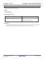
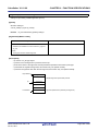
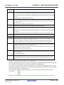
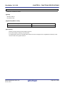
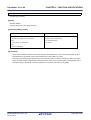
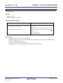
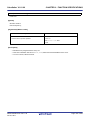
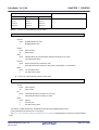
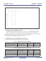
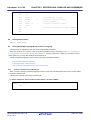
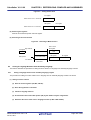
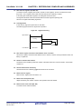
(1) Stack setting
If specify the stack resolution symbol option -s when linking, the symbol _@STEND is generated to mark the
lowest address in the stack, and the symbol _@STBEG is generated to mark the highest address + 1.
-sSTACK
<-- Stack area defined by directive
Figure 2-1. Stack Setting
High
User segment
_@STBEG
Stack
_@STEND
User segment
Lowt
In this case, set the stack pointer as follows.
MOVW
SP, #_@STBEG
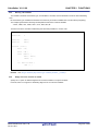
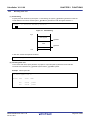
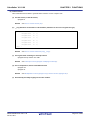
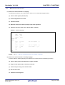
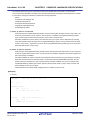
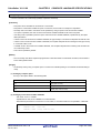
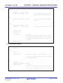
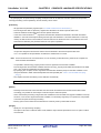
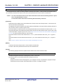
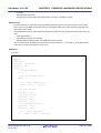
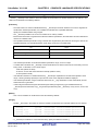
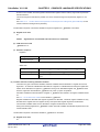
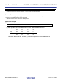
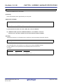
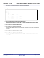
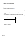
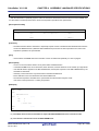
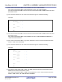
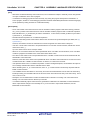
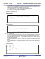
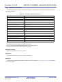
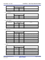
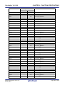
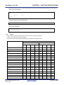
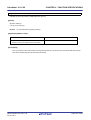
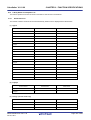
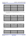
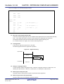
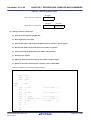
(2) Checking stack area
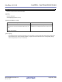
To check the stack area, specify the linker -kp option to output the public symbol list in the link list file.
The stack area is between the _@STEND symbol and the _@STBEG symbol.
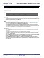
Example Public symbol list
*** Public symbol list ***
MODULE
ATTR
VALUE
NAME
NUM
0FE20H
_@STBEG
NUM
0FB7EH
_@STEND
R20UT0782EJ0100 Rev.1.00
Oct 01, 2011
Page 36 of 836
CubeSuite+ V1.01.00
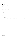
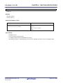
2.5.3
CHAPTER 2 FUNCTIONS
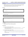
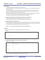
Initializing RAM
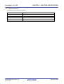
In the default startup routine, initial values are copied to the following areas.
- @@INIT segment
- @@INIS segment
The following areas are zero cleared.
- saddr area (0FE20H to 0FEDFH)
- @@DATA segment
- @@DATS segment
If to initialize areas other than the above, add the appropriate initialization processing code to the startup routine.
Remark
See "7.4 Startup Routines".
R20UT0782EJ0100 Rev.1.00
Oct 01, 2011
Page 37 of 836
CubeSuite+ V1.01.00
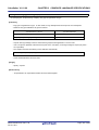
2.6
CHAPTER 2 FUNCTIONS
Link Directives
This section explains link directives.
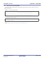
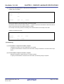
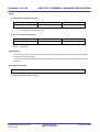
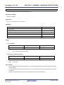
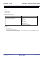
2.6.1
Partitioning default areas
Link directives allow to specify names for memory areas that define. However, care is required regarding the location
of the special function register (SFR) area.
For example, if define two areas in RAM and specify 1) the name "RAM", which is defined by default, and 2) the userdefined name "STACK", then should make sure that the SFR area is contained within the area named RAM.
Example Link directives
MEMORY
STACK : ( 0EF00H, 00100H )
MEMORY
RAM :
Remark
2.6.2
( 0F000H, 01000H )
See "5.1.1 Link directives".
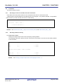
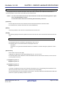
Specifying section allocation
(1) Specifying areas
When specifying the allocation of a section, can specify a memory area.
Use the MERGE quasi directive to allocate the target section in a memory area.
Example Allocate input segment SEG1 to memory area MEM1.
MEMORY
ROM : ( 0000H, 1000H )
MEMORY
MEM1 : ( 1000H, 2000H )
MERGE
SEG1 : = MEM1
Remark
See "5.1.1 Link directives".
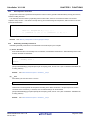
(2) Specifying addresses
When specifying the allocation of a section, can specify addresses.
Use the MERGE quasi directive to specify the allocation address of the target section.
Example Allocate input segment SEG1 to address 500H.
MEMORY
ROM : ( 0000H, 1000H )
MERGE
SEG1 : AT ( 500H )
Remark
See "5.1.1 Link directives".
R20UT0782EJ0100 Rev.1.00
Oct 01, 2011
Page 38 of 836
CubeSuite+ V1.01.00
2.7
CHAPTER 2 FUNCTIONS
Reducing Code Size
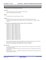
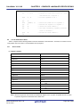
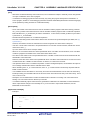
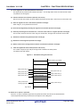
This section explains techniques for reducing the code size.
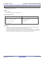
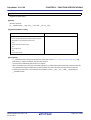
2.7.1
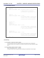
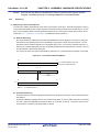
Using extended functions to generate efficient object code
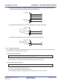
When 78K0 application product is developed, 78K0 C compiler generates efficient object code by using the saddr and
callt, or callf areas in the device.
- Using external variables
if (saddr area available)
use sreg/__sreg variables/
or compiler
- Using 1 bit data
if (saddr area available)
use bit/boolean/__boolean type variables
- Function definitions
if (frequently called function)
if (callt area available)
Use as __callt/callt function (effective for reducing code size and improving execution speed)
if (callf area available)
Use as __callf/callf function (effective for reducing code size and improving execution speed)
if (not used recursively)
Use as __leaf/norec function
if (automatic variables are not used)
Use as noauto function
if (automatic variables are used &&saddr area is usable)
register declaration
(1) Using external variables
If available in the saddr area when defineing external variables, define external variables as sreg/__sreg variables.
sreg/__sreg variables are shorter instruction code than the instructions to memory. Object code will be smaller and
execution speed will be faster. (Instead of the sreg variables, can use the compiler -rd option.)
sreg/__sreg variable define :
extern sreg int
variable-name ;
extern __sreg int variable-name ;
Remark
See "How to use the saddr area (sreg/__sreg)".
R20UT0782EJ0100 Rev.1.00
Oct 01, 2011
Page 39 of 836
CubeSuite+ V1.01.00
CHAPTER 2 FUNCTIONS
(2) Using 1 bit data
When using only 1 bit of data, define a bit type (or boolean/__boolean type) variable. The compiler generates bit
operation instructions to manipulate bit/boolean/__boolean type variables. Like sreg variables, they are stored in
the saddr area for smaller code and faster execution speed.
bit/boolean type variable define :
bit
variable-name ;
boolean
variable-name ;
__boolean variable-name ;
Remark
See "bit type variables (bit), boolean type variables (boolean/__boolean)".
(3) Function definitions
Functions that are called over and over should be written in a way that reduces the size of the object code or
modifies the function structure to improve execution speed. When the functions can use the callt area, they should
be declared as callt functions. When they can use the callf area, they should be declared as callf functions. callt/
callf functions are called by using the callt/callf areas of the device, so they can be called by code that is shorter
than normal function calls.
When a function does not call other functions, it can be declared as a __leaf/norec function. No pre/postprocessing (stack frame) code is generated for norec functions. This reduces the size of the object code and
improves execution speed compared to ordinary functions.
Definition of callt function : callt
int
tsub ( )
{
int
tsub ( )
{
int
tsub ( )
{
:
}
Definition of norec function : norec
:
}
Definition of callf function : callf
:
}
Remark
See "callt functions (callt/__callt)", "norec functions (norec)" and "callf functions (callf/__callf)".
(4) Optimization option
The following optimization option emphasizes object code size.
-qx3, or -qx4
Specify the -qx2 (default) option if execution speed is to be emphasized.
-qx4 reduces the code size by "subroutine-ization of a common code" and calling "library for the stack access" in
addition to -qx3. Therefore the execution speed has the possibility of slowing compared with -qx3.
Adding the __sreg qualifier to variable declarations can reduce code size and improve execution speed. However,
this is restricted to the case when space is available in the saddr area. A build error occurs when there is not
enough space, and when the saddr area cannot be used.
In addition, object code efficiency can be improved by using the extended functions supported by 78K0 C compiler
in C source code.
R20UT0782EJ0100 Rev.1.00
Oct 01, 2011
Page 40 of 836
CubeSuite+ V1.01.00
CHAPTER 2 FUNCTIONS
Without changing the C source code by the thing compiled using optimization option in addition to use in saddr
area, it's possible to generate a high-quality object.
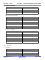
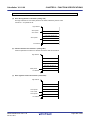
(5) Using extended functions
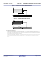
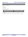
- Function definitions
if (function to be called several times)
iif (not used recursively)
Use as __leaf/norec function
if (automatic variables not used)
Use as noauto function
if (use automatic variables && saddr area available)
Register definitions
if (use internal static variable) && (saddr area available)
__sreg definitions
(a) Functions that are not used recursively
If a function will be called over and over again, and it will not be called recursively, then it should be defined as
a __leaf/norec function.
No pre/post-processing (stack frame) code is generated for norec functions. This reduces the size of the object
code and improves execution speed compared to ordinary functions.
Remark
See "norec functions (norec)" and "3.3.4 norec function call interface (only for normal model)" for
the definition of norec functions (norec int rout () ...).
(b) Functions that do not use automatic variables
Functions that do not use automatic variables should be defined as noauto functions. No stack frame is
generated for notuto function. Their arguments will be passed by registers as much as possible. The size of
object code will be reduced and the execution speed will be improved.
Remark
See "noauto functions (noauto)" or "3.3.3 noauto function call interface (only for normal model)"
for the definition of noauto function (noauto int sub1 (int i) ...).
(c) Functions that use automatic variables
When the function for which an automatic variable is used can use saddr area, define register. A register
definitions allocates a defined object to a register.
Programs that use registers are shorter object and faster execution than programs that use memory.
Remark
About defining register variables (register int i ; ...), see "Register variables (register)".
(d) Functions that use internal static variables
When the function for which an internal static variables is used can use saddr area, define __sreg or specify
the -rs option. Like sreg variables, they are possible to shorter object and faster execution.
Remark
See "How to use the saddr area (sreg/__sreg)".
R20UT0782EJ0100 Rev.1.00
Oct 01, 2011
Page 41 of 836
CubeSuite+ V1.01.00
CHAPTER 2 FUNCTIONS
(6) Other functions
Other extended functions allow to generate faster execution or more compact code.
(a) Use SFR names (or SFR bit names)
#pragma sfr
Remark
See "How to use the sfr area (sfr)".
(b) __sreg definitions for bit fields of 1-bit members (members can also use unsigned char type)
__sreg struct
bf {
unsigned char
a : 1 ;
unsigned char
b : 1 ;
unsigned char
c : 1 ;
unsigned char
d : 1 ;
unsigned char
e : 1 ;
unsigned char
f : 1 ;
} bf_1 ;
Remark
See "How to use the saddr area (sreg/__sreg)".
(c) Use register bank switching for interrupt routines
#pragma interrupt INTP0 inter RB1
Remark
See "Interrupt functions (#pragma vect/#pragma interrupt)".
(d) Use of multiplication, division embedded function
#pragma mul
#pragma div
Remark
See "Multiplication function (#pragma mul)", Division function (#pragma div)".
(e) Described by assembly language to be faster modules.
R20UT0782EJ0100 Rev.1.00
Oct 01, 2011
Page 42 of 836
CubeSuite+ V1.01.00
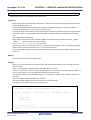
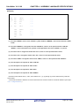
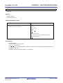
2.7.2
CHAPTER 2 FUNCTIONS
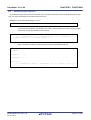
Calculating complex expressions
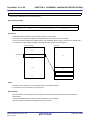
The following example shows the most reasonable way to calculate an expression whose result will always fit into byte
type, even when intermediate results require double word type.
Example Find the rounded percentage c of b in a.
c = ( a x 100 + b / 2 ) / b
In a function like the following, the variable for the result c must be defined as a long int, requiring 4 bytes
of area when a single byte would have been enough.
void
_x ( ) {
c = ( ( unsigned long int ) a * ( unsigned long int ) 100 + ( unsigned long int ) b
/ ( unsigned long int ) 2 ) / ( unsigned long int ) b ;
}
This can be written as follows, if using double word type for intermediate results only.
#pragma mul
#pragma div
unsigned int
a, b ;
unsigned char
c ;
void
_x ( ) {
c = ( unsigned char ) divux ( ( unsigned long ) ( b / 2 ) + muluw ( a, 100 ), b ) ;
}
R20UT0782EJ0100 Rev.1.00
Oct 01, 2011
Page 43 of 836
CubeSuite+ V1.01.00
2.8
CHAPTER 2 FUNCTIONS
Compiler and Assembler Mutual References
This section explains compiler and assembler mutual references.
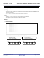
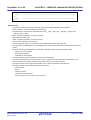
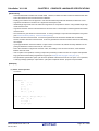
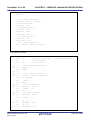
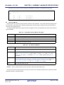
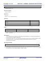
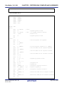
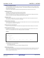
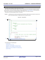
2.8.1
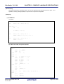
Mutually referencing variables
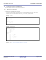
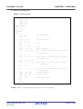
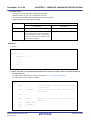
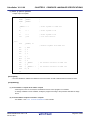
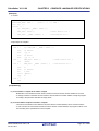
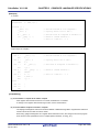
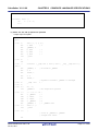
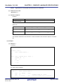
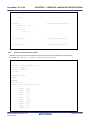
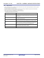
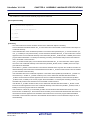
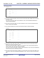
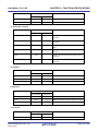
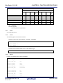
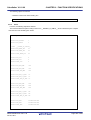
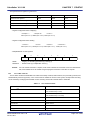
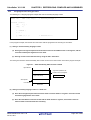
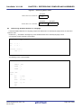
(1) Reference a variable defined in C language
To reference a extern variable defined in a C program from an assembly language routine, define extern.
Prefix the name of the variable with an underscore (_) in the assembly language module.
Example C source
extern void
char
c = 0 ;
int
i = 0 ;
subf ( void ) ;
void main ( void ) {
subf ( ) ;
}
Example Assembly source
$PROCESSOR ( F051144 )
PUBLIC
_subf
EXTRN
_c
EXTRN
_i
@@CODE CSEG
_subf :
MOV
a , #04H
MOV
!_c , a
MOVW
ax , #07H ; 7
MOVW
!_i , ax
RET
END
Remark
See "9.5 Referencing Variables Defined in C Language".
R20UT0782EJ0100 Rev.1.00
Oct 01, 2011
Page 44 of 836
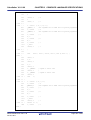
CubeSuite+ V1.01.00
CHAPTER 2 FUNCTIONS
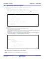
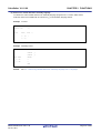
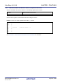
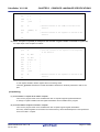
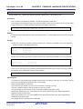
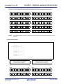
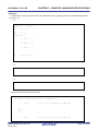
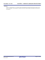
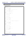
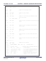
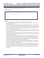
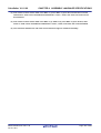
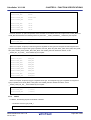
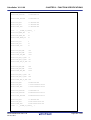
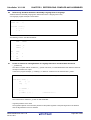
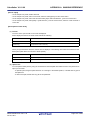
(2) Reference a variable defined in assembly language
To reference a extern variable defined in an assembly language program from a C routine, define extern.
Prefix the name of the variable with an underscore (_) in the assembly language routine.
Example C source
extern char
c ;
extern int
i ;
void
subf ( void ) {
c = 'A' ;
i = 4 ;
}
Example Assembly source
NAME ASMSUB
PUBLIC
_i
PUBLIC
_c
ABC DSEG
BASEP
_i : DW
0
_c : DB
0
END
Remark
See "9.6 Referencing Variables Definted in Assembly Language from C Language".
R20UT0782EJ0100 Rev.1.00
Oct 01, 2011
Page 45 of 836
CubeSuite+ V1.01.00
2.8.2
CHAPTER 2 FUNCTIONS
Mutually referencing functions
(1) Reference a function defined in C language
The following procedure is used to call functions written in C from assembly language routines.
(a) Save the work registers (AX, BC, DE)
(b) Push the arguments on the stack
(c) Call the C function
(d) Adjust the stack pointer (SP) by the byte length of the arguments
(e) Reference the return value of the C function (BC, or DE, BC)
Example Assembly language
$PROCESSOR ( F051144 )
NAME
FUNC2
EXTRN
_CSUB
PUBLIC
_FUNC2
@@CODE CSEG
_FUNC2 :
movw
ax, #20H
; Set 2nd argument ( j )
push
ax
movw
ax, #21H
; Set 1st argument ( i )
call
!_CSUB
; Call "CSUB ( i, j )"
pop
ax
ret
END
Remark
See "9.4 Calling C Language Routines from Assembly Language".
(2) Reference a function defined in assembly language
Functions defined in assembly language to be called from C functions perform the following processing.
(a) Save the base pointer and saddr area for register variables
(b) Copy the stack pointer (SP) to the base pointer (HL)
(c) Perform the processing of the function FUNC
(d) Set the return value
(e) Restore the saved registers
R20UT0782EJ0100 Rev.1.00
Oct 01, 2011
Page 46 of 836
CubeSuite+ V1.01.00
CHAPTER 2 FUNCTIONS
(f) Return to the function main
Example Assembly language
$PROCESSOR ( F051144 )
PUBLIC _FUNC
PUBLIC _DT1
PUBLIC _DT2
@@DATA DSEG UNITP
_DT1 : DS ( 2 )
_DT2 : DS ( 4 )
@@CODE CSEG
_FUNC :
PUSH
HL
PUSH
AX
MOVW
AX , SP
MOVW
HL , AX
MOV
A , [ HL ]
XCH
A , X
MOV
A , [ HL + 1 ]
; save base pointer
; copy stack pointer
; arg1
; arg1
MOVW
!_DT1 , AX
; move 1st argument ( i )
MOV
A , [ HL + 8 ]
; arg2
(add 6 to the offset when the argument is
in the bank area)
XCH
A , X
MOV
A , [ HL + 9 ]
; arg2
(add 6 to the offset when the argument is
in the bank area)
MOVW
!_DT2 + 2 , AX
MOV
A , [ HL + 6 ]
; arg2
(add 6 to the offset when the argument is
in the bank area)
XCH
A , X
MOV
A , [ HL + 7 ]
; arg2
MOVW
!_DT2 , AX
; move 2nd argument ( l )
MOVW
BC , #0AH
; set return value
POP
AX
POP
HL
(add 6 to the offset when the argument is
in the bank area)
; restore base pointer
RET
END
Remark
See "9.3 Calling Assembly Language Routines from C Language".
R20UT0782EJ0100 Rev.1.00
Oct 01, 2011
Page 47 of 836
CubeSuite+ V1.01.00
2.8.3
CHAPTER 2 FUNCTIONS
When the assembler calls functions written in C, registers must be saved
When the assembler calls a function written in C, the following registers must be saved.
hl register
Saved on the side of the C function.
ax, bc, de register
These are work registers, so they may be used by the C function.
Save the above registers on the assembler side before calling the function.
Example Save ax, bc, and de registers before calling _c_function.
push
ax
push
bc
push
de
call
!_c_function
pop
de
pop
bc
pop
ax
; Function written in C
See "CHAPTER 9 REFERENCING COMPILER AND ASSEMBLER" for the details.
R20UT0782EJ0100 Rev.1.00
Oct 01, 2011
Page 48 of 836
CubeSuite+ V1.01.00
CHAPTER 3 COMPILER LANGUAGE SPECIFICATIONS
CHAPTER 3 COMPILER LANGUAGE SPECIFICATIONS
This chapter explains the language specifications supported by 78K0 C compiler.
3.1
Basic Language Specifications
The C compiler supports the language specifications stipulated by the ANSI standards. These specifications include
items that are stipulated as processing definitions. This chapter explains the language specifications of the items
dependent on the processing system of the micro processors for 78K0 microcontrollers.
The differences between when options strictly conforming to the ANSI standards are used and when those options are
not used are also explained.
See "3.2 Extended Language Specifications" for extended language specifications explicitly added by 78K0 C compiler.
3.1.1
Processing system dependent items
This section explains items dependent on processing system in the ANSI standards.
(1) Data types and sizes
The byte order in multibyte data types is "from least significant to most significant byte" Signed integers are
expressed by 2's complements. The sign is added to the most significant bit (0 for positive or 0, and 1 for
negative).
- The number of bits of 1 byte is 8.
- The number of bytes, byte order, and encoding in an object files are stipulated below.
Table 3-1. Data Types and Sizes
Data Types
Sizes
char
1 byte
int, short
2 bytes
long, float, double
4 bytes
Pointer
Pointer variable (except function pointers when using bank function (-mf)
): 2 bytes
Function pointers (when using bank function (-mf) ): 4 bytes
(2) Translation stages
The ANSI standards specify eight translation stages (known as "phases" ) of priorities among syntax rules for
translation. The arrangement of "non-empty white space characters excluding line feed characters" which is
defined as processing system dependent in phase 3 "Decomposition of source file into preprocessing tokens and
white space characters" is maintained as it is without being replaced by single white space character.
However, tabs are replaced by the space character specified with the -lt option.
(3) Diagnostic messages
When syntax rule violation or restriction violation occurs on a translation unit, the compiler outputs as error
message containing source file name and (when it can be determined) the number of line containing the error.
These error messages are classified into three types: "alarm", "fatal error", and "other error" messages.
R20UT0782EJ0100 Rev.1.00
Oct 01, 2011
Page 49 of 836
CubeSuite+ V1.01.00
CHAPTER 3 COMPILER LANGUAGE SPECIFICATIONS
(4) Free standing environment
(a) The name and type of a function that is called on starting program processing are not stipulted in a
free-standing environmentNote. Therefore, it is dependent on the user-own coding and target system.
Note Environment in which a C Language source program is executed without using the functions of the
operating system.
In the ANSI Standard two environments are stipulated for execution environment: a free-standing environment and a host environment. The 78K0 C compiler does not supply a host environment at present.
(b) The effect of terminating a program in a free-standing environment is not stipulated. Therefore, it is
dependent on the user-own coding and target system.
(5) Program execution
The configuration of the interactive unit is not stipulated.
Therefore, it is dependent on the user-own coding and target system.
(6) Character set
The values of elements of the execution environment character set are ASCII codes.
(7) Multi-byte characters
Multi-byte characters are not supported by character constants and character strings.
However, Japanese description in comments is supported.
(8) Significance of character display
The values of expanded notation are stipulated as follows.
Table 3-2. Expanded Notation and Meaning
Expanded Notation
Value (ASCII)
Meaning
\a
07
Alert (Warning tone)
\b
08
Backspace
\f
0C
Form feed (New Page)
\n
0A
New line (Line feed)
\r
0D
Carriage return (Restore)
\t
09
Horizontal tab
\v
0B
Vertical tab
(9) Translation Limit
The limit values of translation are explained below.
The values marked with * are guaranteed values. These values may be exceeded in some cases, but the
operation is not guaranteed.
R20UT0782EJ0100 Rev.1.00
Oct 01, 2011
Page 50 of 836
CubeSuite+ V1.01.00
CHAPTER 3 COMPILER LANGUAGE SPECIFICATIONS
Table 3-3. Translation Limit Values
Contents
Number of nesting levels of compound statements, repetitive control structures, and
Limit Values
45
selective control structures
(However, dependent on the number of "case" labels)
Number of nesting levels of condition embedding
255
Number of pointers, arrays, and function declarators (in any combination) qualifying
12
one arithmetic type, structure type, union type, or incomplete type in one declaration
Number of nesting levels enclosed by parentheses in a complete declarator
591*
Number of nesting levels of an expression enclosed by parentheses in a complete
32
expression
Valid number of first characters in a macro name
256
Valid number of first characters of an external identifier
249
Valid number of first characters in an internal identifier
249
Number of identifiers having an external identifier in one translation unit
1024*
Number of identifiers having the valid block range declared in one basic block
255
Number of macro identifiers simultaneously defined in one translation unit
32767
Number of dummy arguments in one function definition and number of actual
39*
arguments in one function call
Number of dummy arguments in one macro definition
31
Number of actual arguments in one macro call
31
Number of characters in one logical source line
2048*
One character string constant after concatenation, or number of characters in a wide
509*
character string constant
Object size of 1-file (Data is indicated)
65535
Number of nesting levels for include (#include) files
50
Number of "case" labels for one "switch" statement
257
(including those nested, if any)
Number of source lines per compilation unit
65535*
Number of nested function calls
40*
Total size of code, data, and stack segments in a single object module
65535
Number of members of a single structure or single union
256
Number of enumerate constants in a single enumerate type
255
Number of nesting levels of a structure or union definition in the arrangement of a
15
single structure declaration
Nesting of initializer elements
15
Number of function definitions in a single source file
4095
Macro nesting
200
Number of include file paths
64
R20UT0782EJ0100 Rev.1.00
Oct 01, 2011
Page 51 of 836
CubeSuite+ V1.01.00
CHAPTER 3 COMPILER LANGUAGE SPECIFICATIONS
(10) Quantitative limit
(a) The limit values of the general integer types (limits.h file)
The limits.h file specifies the limit values of the values that can be expressed as general integer types (char
type, signed/unsigned integer type, and enumerate type).
Because multibyte characters are not supported, MB_LEN_MAX does not have a corresponding limit.
Consequently, it is only defined with MB_LEN_MAX as 1.
If a -qu option is specified, CHAR_MIN is 0, and CHAR_MAX takes the same value as UCHAR_MAX. The
limit values defined by the limits.h file are as follows.
Table 3-4. Limit Values of General Integer Type (limits.h File)
Name
CHAR_BIT
Value
Meaning
+8
The number of bits (= 1 byte) of the minimum object not
in bit field
SCHAR_MIN
-128
Minimum value of signed char
SCHAR_MAX
+127
Maximum value of signed char
UCHAR_MAX
+255
Maximum value of unsigned char
CHAR_MIN
-128
Minimum value of char
CHAR_MAX
+127
Maximum value of char
SHRT_MIN
-32768
Minimum value of short int
SHRT_MAX
+32767
Maximum value of short int
USHRT_MAX
+65535
Maximum value of unsigned short int
INT_MIN
-32768
Minimum value of int
INT_MAX
+32767
Maximum value of int
UINT_MAX
+65535
Maximum value of unsigned int
LONG_MIN
-2147483648
Minimum value of long int
LONG_MAX
+2147483647
Maximum value of long int
ULONG_MAX
+4294967295
Maximum value of unsigned long int
(b) The limit values of the floating-point type (float.h file)
The limit values related to characteristics of the floating-point type are defined in float.h file.
The limit values defined by the float.h file are as follows.
Table 3-5. Definition of Limit Values of Floating-point Type (float.h File)
Name
FLT_ROUNDS
Value
+1
Meaning
Rounding mode for floating-point addition.
1 for the 78K0 microcontrollers (rounding in the nearest
direction).
FLT_RADIX
+2
FLT_MANT_DIG
+24
DBL_MANT_DIG
Radix of exponent (b)
Number of numerals (p) with FLT_RADIX of floatingpoint mantissa as base
LDBL_MANT_DIG
R20UT0782EJ0100 Rev.1.00
Oct 01, 2011
Page 52 of 836
CubeSuite+ V1.01.00
CHAPTER 3 COMPILER LANGUAGE SPECIFICATIONS
Name
FLT_DIG
Value
+6
Meaning
Number of digits of a decimal numberNote 1 (q) that can
round a decimal number of q digits to a floating-point
DBL_DIG
number of p digits of the radix b and then restore the
LDBL_DIG
FLT_MIN_EXP
decimal number of q
-125
Minimum negative integer (emin) that is a normalized
floating-point number when FLT_RADIX is raised to the
DBL_MIN_EXP
power of the value of FLT_RADIX minus 1.
LDBL_MIN_EXP
FLT_MIN_10_EXP
-37
Minimum negative integerlog10bemin-1 that falls in the
range of a normalized floating-point number when 10 is
DBL_MIN_10_EXP
raised to the power of its value.
LDBL_MIN_10_EXP
FLT_MAX_EXP
+128
Maximum integer (emax) that is a finite floating-point
number that can be expressed when FLT_RADIX is
DBL_MAX_EXP
raised to the power of its value minus 1.
LDBL_MAX_EXP
FLT_MAX_10_EXP
+38
Maximum value of finite floating-point numbers that can
be expressed
DBL_MAX_10_EXP
(1 - b-p) * bemax
LDBL_MAX_10_EXP
FLT_MAX
3.40282347E + 38F
Maximum value of finite floating-point numbers that can
be expressed
DBL_MAX
(1 - b-p) * bemax
LDBL_MAX
FLT_EPSILON
1.19209290E - 07F
specified floating-point number type and the lowest
DBL_EPSILON
value which is greater than 1.
b1 - p
LDBL_EPSILON
FLT_MIN
DifferenceNote 2 between 1.0 that can be expressed by
1.17549435E - 38F
Minimum value of normalized positive floating-point
number
DBL_MIN
bemin - 1
LDBL_MIN
Notes 1.
DBL_DIG and LDBL_DIG are 10 or more in the ANSI standards but are 6 in the 78K0
microcontrollers because both the double and long double types are 32 bits.
2.
DBL_EPSILON and LDBL_EPSILON are 1E-9 or less in the ANSI standards, but 1.19209290E07F in the 78K0 microcontrollers.
(11) Identifier
The initial 249 characters of identifiers are recognized.
Uppercase and lowercase characters are distinguished.
R20UT0782EJ0100 Rev.1.00
Oct 01, 2011
Page 53 of 836
CubeSuite+ V1.01.00
CHAPTER 3 COMPILER LANGUAGE SPECIFICATIONS
(12) char type
A char type with no type specifier (signed, unsigned) specified is treated as a signed integer as the default
assumption.
However, a simple char type can be treated as an unsigned integer by specifying the - qi option of the C compiler.
The types of those that are not included in the character set of the source program required by the ANSI standards
(escape sequence) is converted for storage, in the same manner as when types other than char type are
substituted for a char type.
char
c = '\777';
/* Value of c is -1 */
(13) Floating-point constants
The floating-point constants conform to IEEE754Note.
Note IEEE:Institute of Electrical and Electronics Engineers
Moreover, IEEE754 is a standard to unify specifications such as the data format and numeric range in
systems that handle floating-point operations.
(14) Character constants
(a) Both the character set of the source program and the character set in the execution environment are
basically ASCII codes, and correspond to members having the same value.
(b) The last character of the value of an integer character constant including two or more characters is
valid.
(c) A character that cannot be expressed by the basic execution environment character set or escape
sequence is expressed as follows.
<1> An octal or hexadecimal escape sequence takes the value indicated by the octal or hexadecimal
notation
\077
63
<2> The simple escape sequence is expressed as follows.
\'
'
\"
"
\?
?
\\
\
<3> Values of \a, \b, \f, \n, \r, \t, \v are same as the values explained in "(8) Significance of character
display".
(d) Character constants of multi byte characters are not supported.
(15) Header file name
The method to reflect the string in the two formats (<> and " ") of a header file name on the header file or an external source file name is stipulated in "(32) Loading header file".
R20UT0782EJ0100 Rev.1.00
Oct 01, 2011
Page 54 of 836
CubeSuite+ V1.01.00
CHAPTER 3 COMPILER LANGUAGE SPECIFICATIONS
(16) Comment
A comment can be described in Japanese. The default character code set for Japanese is Shift JIS.
The character code set of the input source file can be specified by the compiler's -z option, or by an environmental
variable. An option specification takes priority over an environment variable specification. However, character
codes are not guaranteed when "none" is specified.
(a) Option specification
-ze | -zn | -zs
(b) Environment variable
LANG78K [euc | none | sjis]
To set environment variables, use the standard procedure for environment.
(17) Signed constants and unsigned constants
If the value of a general integer type is converted into a signed integer of a smaller size, the higher bits are
truncated and a bit string image is copied.
If an unsigned integer is converted into the corresponding signed integer, the internal representation is not
changed.
(18) Floating-points and general integers
If the value of a general integer type is converted into the value of a floating-point type, and if the value to be
converted is within a range that can be expressed but not accurately, the result is rounded to the closest
expressible value.
When the result is just a middle value, it can be rounded to the even number (with the least significant bit of the
mantissa being 0).
(19) double type and float type
In the 78K0 C compiler, a double type is expressed as a floating-point number in the same manner as a float type,
and is treated as 32-bit (single-precision) data
(20) Signed type in operator in bit units
The characteristics of the shift operator conform to the stipulation in"(26) Shift operator in bit units" .
The other operators in bit units for signed type are calculated as unsigned values (as in the bit image).
(21) Members of structures and unions
If the value of a member of a union is stored in a different member, it is stored according to an alignment condition.
Therefore, the members of that union are accessed according to the alignment condition (see "(b) Structure type"
and "(c) Union type" ).
In the case of a union that includes a structure sharing the arrangement of the common first members as a
member, the internal representation is the same, and the result is the same even if the first member common to
any structure is referred.
(22) sizeof operator
The value resulting from the "sizeof" operator conforms to the stipulation related to the bytes in an object in"(1)
Data types and sizes".
For the number of bytes in a structure and union, it is byte including padding area.
R20UT0782EJ0100 Rev.1.00
Oct 01, 2011
Page 55 of 836
CubeSuite+ V1.01.00
CHAPTER 3 COMPILER LANGUAGE SPECIFICATIONS
(23) Cast operator
When a pointer is converted into a general integer type, the required size of the variable is the same as the
following table lists. The bit string is saved as is as the conversion result.
Any integer can be converted by a pointer. However, the result of converting an integer smaller than an int type is
expanded according to the type.
Pointer variable (except function pointers when using bank function (-mf) )
2 bytes
Function pointers (when using bank function (-mf) )
4 bytes
(24) Division/remainder operator
The result of the division operator ("/") when the operands are negative and do not divide perfectly with integer
division, is as follows: If either the divisor or the dividend is negative, the result is the smallest integer greater than
the algebraic quotient.
If both the divisor and the dividend are negative, the result is the largest integer less than the algebraic quotient.
If the operand is negative, the result of the "%" operator takes the sign of the first operand in the expression.
(25) Addition and subtraction operators
If two pointers indicating the elements of the same array are subtracted, the type of the result is int type, and the
size is 2 bytes.
(26) Shift operator in bit units
If E1 of "E1 >> E2" is of signed type and takes a negative value, an arithmetic shift is executed.
(27) Storage area class specifier
The storage area class specifier "register" is declared to increase the access speed as much as possible, but this
is not always effective.
(28) Structure and union specifier
(a) int type bit field sign Simple int type bit fields without a signed or unsigned specifier are treated as
unsigned.
(b) To retain a bit field, a storage area unit to which any address with sufficient size can be assigned can
be allocated. If there is insufficient area, however, the bit field that does not match is packed into to
the next unit according to the alignment condition of the type of the field.
(c) The allocation sequence of the bit field in unit is from lower to higher.
However, the -rb option can be specified for the allocation sequence is from higher to lower.
(d) Each member of the non-bit field of one structure or union is aligned at a boundary as follows
- char and unsigned char types, and arrays of char and unsigned char types: Byte boundary
- Other (including pointers):
R20UT0782EJ0100 Rev.1.00
Oct 01, 2011
2-byte boundary
Page 56 of 836
CubeSuite+ V1.01.00
CHAPTER 3 COMPILER LANGUAGE SPECIFICATIONS
(29) Enumerate type specifier
The type of an enumeration is the first type from among the following which is capable of expressing all of the
enumeration constants.
- signed char
- unsigned char
- signed int
(30) Type qualifier
The configuration of access to data having a type qualified to be "volatile" is dependent upon the address (I/O port,
etc.) to which the data is mapped.
(31) Condition embedding
(a) The value for the constant specified for condition embedding and the value of the character constant
appearing in the other expressions are equal.
(b) The character constant of a single character must not have a negative value.
(32) Loading header file
(a) A preprocessing directive in the form of "#include <character string>"
Unless "filename" begins with the character '\' Note the #include <filename> preprocessor directive instructs the
preprocessor to search for the file specified between the angle brackets (<..>) in the following locations: 1) the
folder specified by the -i option, 2) the folder specified by the INC78K0 environment variable, and 3) the
..\inc78k0 folder relative to the bin folder where cc78k0.exe resides.
If a header file uniformly identified is searched with a character string specified between delimiters "<" and ">",
the whole contents of the header file are replaced.
Note Both "\" and "/" are regarded as the delimiters of a folder.
Example
#include
<header.h>
The search order is as follows.
- The folder specified by the -i option
- The folder specified by the INC78K0 environment variable
- The standard folder
(b) A preprocessing directive in the form of "#include "character string""
Unless "character string" begins with the character '\'Note, the #include "character string" preprocessor directive instructs the preprocessor to search for the file specified between the quotation marks ("..") in the following
locations: 1) the folder that contains the source file, 2) the folder specified by the -i option, 3) the folder specified by the INC78K0 environment variable, and 4) the ..\inc78k0 folder relative to the bin folder where
cc78k0.exe resides.
If the file specified between the quotation mark delimiters is found, the #include directive line is replaced with
the entire contents of the file.
Note Both "\" and "/" are regarded as the delimiters of a folder.
R20UT0782EJ0100 Rev.1.00
Oct 01, 2011
Page 57 of 836
CubeSuite+ V1.01.00
CHAPTER 3 COMPILER LANGUAGE SPECIFICATIONS
Example
#include
"header.h"
The search order is as follows.
- The folder that contains the source file
- The folder specified by the -i option
- The folder specified by the INC78K0 environment variable
- The standard folder
(c) The format of "#include preprocessing character phrase string"
The format of "#include preprocessing character phrase string" is treated as the preprocessing character
phrase of single header file only if the preprocessing character phrase string is a macro that is replaced to the
form of <character string> or "character string".
(d) A preprocessing directive in the form of "#include <character string>"
Between a string delimited (finally) and a header file name, the length of the alphabetic characters in the
strings is identified,
And the file name length valid in the compiler operating environment is valid.
The folder that searches a file conforms to the above stipulation.
(33) #pragma directive
#pragma directives are one of the preprocessing directive types defined by the ANSI standard. The string that
follows #pragma the compiler to translate in an implementation-defined manner.
When a #pragma directive is not recognized by the compiler, it is ignored and translation continues. If the directive
adds a keyword, then an error occurs if the C source contains that keyword. To avoid the error, delete the keyword
from the source or exclude it with #ifdef.
(34) Predefined macro names
All the following macro names are supported.
Macros not ending with "_ _ " are supplied for the sake of former C language specifications (K&R specifications).
To perform processing strictly conforming to the ANSI standards, use macros with "_ _ " before and after.
Table 3-6. List of Supported Macros
Macro Name
Definition
__LINE__
Line number of source line at that point (decimal).
__FILE__
Name of assumed source file (character string constant).
__DATE__
Date of translating source file (character string constant in the form of "Mmm dd yyyy" ).
Here, the name of the month is the same as that created by the asctime function
stipulated by ANSI standards (3 alphabetic characters with only the first character is
capital letter) (The first character of dd is blank if its value is less than 10).
__TIME__
Translation time of source file (character string constant having format "hh:mm:ss" similar
to the time created by the asctime function).
__STDC__
Decimal constant 1, indicating conformance to the ANSI standard.Note
__K0__
Decimal constant 1
R20UT0782EJ0100 Rev.1.00
Oct 01, 2011
Page 58 of 836
CubeSuite+ V1.01.00
CHAPTER 3 COMPILER LANGUAGE SPECIFICATIONS
Macro Name
Definition
__STATIC_MODEL__
Decimal constant 1 (when static model is specified).
__CHAR_UNSIGNED__
Decimal constant 1 (When the -qu option was specified.)
__CA78K0__
Decimal constant 1
CPUmacro
Decimal constant 1 of a macro indicating the target CPU.
A character string indicated by "product type specification" in the device file with "_ _ "
prefixed and suffixed is defined.
Note Defined when the -za option is specified
(35) Definition of special data type
NULL, size_t, and ptrdiff_t defined by stddef.h file are as follows.
Table 3-7. Definition of NULL, size_t, ptrdiff_t (stddef.h File)
NULL/size_t/ptrdiff_t
3.1.2
Definition
NULL
((void *) 0)
size_t
unsigned int
ptrdiff_t
int
Internal representation and value area of data
This section explains the internal representation and value area of each type for the data handled by the 78K0 C compiler.
(1) Basic types
The basic types, also called arithmetic types, consist of the integer types and the floating point types.
The integer types can be classified into the char type, signed integer types, unsigned integer types, and
enumeration type.
(a) Integer types
Integer types can be divided into 4 categories, as follows. Integer types are expressed as binary 0s and 1s.
- char type
- signed integer types
- unsigned integer types
- enumeration types
<1> char type
The char type is large enough to store any member of the execution character set.
If a member of the basic execution character set is stored in a char object, its value is guaranteed to be
nonnegative.
Objects other than characters are treated as signed integers.
If an overflow occurs when a value is stored, the overflow part is ignored.
<2> Signed integer types
There are four signed integer types, as follows.
- signed char
R20UT0782EJ0100 Rev.1.00
Oct 01, 2011
Page 59 of 836
CubeSuite+ V1.01.00
CHAPTER 3 COMPILER LANGUAGE SPECIFICATIONS
- short int
- int
- long int
An object defined as signed char type occupies the same amount of area as a "plain" char.
A "plain" int has the natural size suggested by the CPU architecture of the execution environment.
For each of the signed integer types, there is a corresponding unsigned integer type that uses the same
amount of area.
The positive number of a signed integer type is a subset of the the unsigned integer type.
<3> Unsigned integer types
Unsigned integer types are designated by the keyword "unsigned".
A computation involving unsigned integer types can never overflow, because a result that cannot be
represented by the resulting unsigned integer type is reduced modul the number that is one greater than
the largest value that can be represented by the resulting type.
<4> Enumeration types
An enumeration comprises a set of named integer constant values.
Each distinct enumeration constitutes a different enumerated type.
Each enumeration constitutes a enumerated type.
(b) Floating point types
There are three real floating types, as follows.
- float
- double
- long double
Like the float type, the double and long double types of 78K0 C compiler are supported as floating point representations of the single-precision normalized numbers defined in ANSI/IEEE 754-1985. This means that the
float, double, and long double types have the same value range.
Table 3-8. Value Ranges by Type
Type
Value Range
(signed) char
-128 to +127
unsigned char
0 to 255
(signed) short int
-32768 to +32767
unsigned short int
0 to 65535
(signed) int
-32768 to +32767
unsigned int
0 to 65535
(signed) long int
-2147483648 to +2147483647
unsigned long int
0 to 4294967295
float
1.17549435E - 38F to 3.40282347E + 38F
double
1.17549435E - 38F to 3.40282347E + 38F
long double
1.17549435E - 38F to 3.40282347E + 38F
R20UT0782EJ0100 Rev.1.00
Oct 01, 2011
Page 60 of 836
CubeSuite+ V1.01.00
Remarks 1.
CHAPTER 3 COMPILER LANGUAGE SPECIFICATIONS
The "signed" type specifier may be omitted. However, when it is omitted for the char type, a
compiling condition (option) determines whether the type is the signed char or unsigned char
type.
2.
The short int and int types have the same value range, but they are treated as different types.
3.
The unsigned short int and unsigned int types have the same value range, but they are treated
as different types.
4.
The float, double, and long double types have the same value range, but they are treated as
different types.
5.
The ranges of the float, double, and long double types are ranges of absolute values.
The following show the specifications of floating point numbers (float type).
<1> Format
The floating point number format is shown below.
Figure 3-1. Floating Point Number Format
(High address)
s
e
m
31 30
(Low address)
23 22
0
Numerical values in this format are as follows.
(Value of sign)
( -1 )
s
(Value of exponent)
* (Value of mantissa) * 2
Sign (1 bit)
0 for a positive number and 1 for a negative number.
e
Exponent (8 bits)
A base-2 exponent is expressed as a 1-byte integer (expressed by 2's complement in the case of a
negative), after the further addition of a bias of 7FH. These relationships are shown in the table below.
Exponent (Hexadecimal)
m
Value of Exponent
FE
127
:
:
81
2
80
1
7F
0
7E
-1
:
:
01
-126
Mantissa (23 bits)
The mantissa is expressed as an absolute value, with bit positions 22 to 0 equivalent to the 1st to 23rd
places of a binary number.
Except for when the value of the floating point is 0, the value of the exponent is always adjusted so that
the mantissa is within the range of 1 to 2 (normalization). The result is that the position of 1 (i.e. the
value of 1) is always 1, and is thus represented by omission in this format.
R20UT0782EJ0100 Rev.1.00
Oct 01, 2011
Page 61 of 836
CubeSuite+ V1.01.00
CHAPTER 3 COMPILER LANGUAGE SPECIFICATIONS
<2> Expression of zero
When exponent = 0 and mantissa = 0, + 0 is expressed as follows.
(Value of sign)
( -1 )
* 0
<3> Expression of infinity
When exponent = FFH and mantissa = 0, + ∞ is expressed as follows.
(Value of sign)
* ∞
( -1 )
<4> Denormalized values
When exponent = 0 and mantissa ≠ 0, the denormalized value is expressed as follows.
(Value of sign)
( -1 )
Remark
-126
* (Value of mantissa) * 2
The mantissa value here is a number less than 1, so bit positions 22 to 0 of the mantissa
express the 1st to 23rd decimal places.
<5> Expression of NaN (Not-a-number)
When exponent = FFH and mantissa ≠ 0, NaN is expressed, regardless of the sign.
<6> Rounding of computation results
Numerical values are rounded down to the nearest even number. If the computation result cannot be
expressed in the above floating point format, round to the nearest expressible number.
If there are 2 values that can express the differential of the prerounded value, round to an even number
(a number whose least significant binary bit is 0).
<7> Exceptions
There are 5 types of exceptions, as shown in the table below.
Table 3-9. Numerical Exception
Exception
Return Value
Underflow
Denormalized number
Inexact
+0
Overflow
+∞
Division by zero
+∞
Invalid operation
NaN
When an exception occurs, calling the matherr function causes a warning to appear.
R20UT0782EJ0100 Rev.1.00
Oct 01, 2011
Page 62 of 836
CubeSuite+ V1.01.00
CHAPTER 3 COMPILER LANGUAGE SPECIFICATIONS
(2) Character types
There are 3 char data types.
- char
- signed char
- unsigned char
(3) Incomplete types
There are 4 incomplete data types.
- Arrays with indefinite object size
- Structures
- Unions
- void type
(4) Derived types
There are 5 derived data types.
- Array type
- Structure type
- Union type
- Function type
- Pointer type
(a) Array type
An array type describes a contiguously allocated set of objects with a particular member object type, called the
element type.
All member objects have the area of the same size. Array types and individual elements can be specified. It is
not possible to create an incomplete array type.
(b) Structure type
A structure type describes a sequentially allocated set of member objects, each of which has an optionally
specified name and possibly a distinct type.
Remark
Array and structure types are collectively called aggregate types. The member objects in
aggregate types are allocated sequentially.
(c) Union type
A union type describes an overlapping set of member objects.
Each member of a union has an optionally specified name and possibly a distinct type. Union members can
be specified individually.
(d) Function type
A function type describes a function with the return value of the specified type.
A function type is characterized by its return value type and the number and types of its parameters.
If its return value type is T, the function is called a "function returning T".
(e) Pointer type
A pointer type may be derived from a function type, an object type, or an incomplete type, called the
referenced type.
A pointer type describes an object whose value provides a reference to an entity of the referenced type.
A pointer type derived from the referenced type T is sometimes called a "pointer to T".
R20UT0782EJ0100 Rev.1.00
Oct 01, 2011
Page 63 of 836
CubeSuite+ V1.01.00
3.1.3
CHAPTER 3 COMPILER LANGUAGE SPECIFICATIONS
Memory
The memory model is determined by the memory space of the target device.
(1) Memory models
The memory model refers to 64K in total with the code and data section because the memory space is at most 64K
Byte. If the bank function is used, more than 64K is allowed only for the code section.
(2) Register banks
- The current register bank is set to "RB0" by the 78K0 C compiler startup routine. Unless it is changed, it
remains set to register bank 0.
- It's set as a specified register bank at the start of the interrupt function where register bank change designation
was done.
(3) Memory space
78K0 C compiler utilizes the following memory space.
(a) Normal model
Figure 3-2. Utilization of Memory Space (Normal Model)
Address
Size
Use
(bytes)
00
40 - 7FH
0800 - 0FFFH
CALLT table
64
CALLF entry
2048
FE
20 - B7H
sreg variables, boolean variables
152
FE
B8 - BFH
Arguments of runtime library
8
FE
C0 - C7H
Arguments of norec functions
8
FE
C8 - CFH
Automatic variables of norec functions
8
FE
D0 - DFH
Register variables
16
FE
E0 - F7H
RB3-RB1
Work registersNote
24
F8 - FFH
RB0
Work registers
8
FF
00 - FFH
sfr variables
256
Note Used when the register bank is specified.
R20UT0782EJ0100 Rev.1.00
Oct 01, 2011
Page 64 of 836
CubeSuite+ V1.01.00
CHAPTER 3 COMPILER LANGUAGE SPECIFICATIONS
(b) Static model (at -sm16 specification)
Figure 3-3. Utilization of Memory Space (Static Model)
Address
Use
Size
(bytes)
40 - 7FH
00
0800 - 0FFFH
CALLT table
64
CALLF entry
2048
FE
20 - CFH
sreg variables, boolean type variables
176
FE
D0 - D7H
Shared areaNote 2
16
FE
Consecutive
areas between
20 and DFH
For arguments, automatic variables, and workNote 3
8
FE
E0 - F7H
RB3-RB1
Work registersNote
24
F8 - FFH
RB0
Work registers
8
00 - FFH
sfr variables
FF
Notes 1.
2.
256
Used when the register bank is specified.
The area where the compiler uses change with the parameter of the -sm.
Areas not used as shared area can be utilized as sreg variables or boolean type variables.
3.
3.2
Only available when the static model extended option (-zm) is specified.
Extended Language Specifications
This section explains extensions unique to the 78K0 C compiler, which are not specified by theI ANSI (American
National Standards Institute) standard.
The 78K0 C compiler extensions allow to generate code that makes the most effective use of the target device. These
extensions are not necessarily useful in every situation, so recommended to use only those which are useful for purposes. For more information about effective use of the 78K0 C compiler extensions, see "CHAPTER 2 FUNCTIONS".
Use of the 78K0 C compiler extensions introduces microcontroller dependencies into C source programs, but
compatibility on the C language level is maintained. Even if using the 78K0 C compiler extensions in C source programs,
can still port the programs to other microcontrollers with a few easy-to-make modifications.
3.2.1
Macro names
78K0 C compiler defines a macro name to indicate the microcontroller name of the target device and a macro name to
indicate the device name. These device names are specified by a compiling option to generate object code for the target
device or by device classification in the C source code. The following examples define the macro names __K0__and
__F051144_.
See "(34) Predefined macro names" for more information about macro names.
R20UT0782EJ0100 Rev.1.00
Oct 01, 2011
Page 65 of 836
CubeSuite+ V1.01.00
CHAPTER 3 COMPILER LANGUAGE SPECIFICATIONS
Compiling option:
>cc78k0 -cF051144 prime.c ...
Processor type:
#pragma pc ( F051144 )
3.2.2
Keywords
78K0 C compiler defines the following keywords to enable the extended functions. Like ANSI C keywords, these keywords cannot be used as labels or variable names.
All of these keywords are in lowercase. Any token that contains an uppercase character is not regarded as a keyword.
In the following table of keywords added by 78K0 C compiler, keywords that do not begin with "__" can be undefined by
specifying the strict ANSI C conformance option (-za).
Table 3-10. Keywords Added by 78K0 C Compiler
Additional Keyword
Always Defined
Purpose
Undefined When -za Option Is
Specified
__callt
callt
Call functions via callt table
__callf
callf
Call functions via callf area
__sreg
sreg
Allocate variables in saddr area
-
noauto
Generate functions without pre/postprocessing
__leaf
norec
Generate functions without pre/postprocessing
__boolean
boolean
Bit access to saddr and sfr area
-
bit
Bit access to saddr and sfr area
__interrupt
-
Hardware interrupt
__interrupt_brk
-
Software interrupt
__asm
-
ASM statements
__pascal
-
Generate code that removes
arguments to a function from the stack
before the function returns
__flash
-
Firmware ROM functions
__flashf
-
__flashf functions
__directmap
-
Absolute address mapping
__temp
-
Temporary variables
__mxcall
-
__mxcall function
(1) Functions
The callt, __callt, callf, __callf, noauto, norec, __leaf, __interrupt, __interrupt_brk, , __flash, __flashf, __pascal
keywords are attribute qualifiers that may be added to the start of function descriptions.
The syntax is shown below.
R20UT0782EJ0100 Rev.1.00
Oct 01, 2011
Page 66 of 836
CubeSuite+ V1.01.00
CHAPTER 3 COMPILER LANGUAGE SPECIFICATIONS
attribute-qualifier ordinary-declarator function-name (parameter-type-list/identifierlist)
Following is an example description .
__callt int
func
( int ) ;
Valid attribute qualifiers are limited to the following (noauto and norec/__leaf cannot be specified at the same time).
Note that callt and __callt, callf and __callf, norec and __leaf are regarded as the same specification. However, the
qualifier that begins with "__" is defined even when the -za option is specified.
callt, callf, noauto, norec, callt noauto, callt norec, noauto callt, norec callt, callf noauto, callf norec, noauto
callf, norec callf, __interrupt, __interrupt_brk, __pascal, __pascal noauto, __pascal callt, __pascal callf,
noauto __pascal, callt __pascal, callf __pascal, callt noauto __pascal, callf noauto __pascal, __flash, __flashf
(2) Variables
sreg and __sreg follow the same rules as the "register" of the C language (See "How to use the saddr area (sreg/
__sreg)" for more information about the sreg keywords).
The bit, boolean, and __boolean type specifiers follow the same rules as the "char" and "int" type specifiers of the
C language. However, they can be applied only to variables declared outside functions (external variables).
The __directmap qualifier follows the same rules as the qualifiers of the C language (See "Absolute address
allocation specification (__directmap)" for details).
Specify the __temp using the same rule as the type modifier of the C language (please see "Temporary variables
(__temp)" for more details).
3.2.3
#pragma directives
#pragma directives are one of the types of preprocessing directives supported by the ANSI C standard. A #pragma
directive instructs the compiler to translate in a specific way, depending on the string that follows the #pragma.
When a compiler encounters a #pragma directive that it does not recognize, it ignores the directive and continues
compiling. If the function of the unrecognized #pragma was to define a keyword, then an error will occur when that
keyword is encountered in the C source. To avoid this, the undefined keyword should be deleted from the C source or
excluded by #ifdef.
78K0 C compiler supports the following #pragma directives, which allow extended functions.
The keyword after #pragma may be specified in either uppercase or lowercase.
See "3.2.4 Using extended functions" for more information about using these directives to enable extended functions.#pragma directive list.
Table 3-11. #pragma Directives List
#pragma Directive
#pragma sfr
Purpose
Use SFR names in C source files.
-> See "How to use the sfr area (sfr)".
#pragma asm
Inserts ASM statement in C source.
-> See "ASM statements (#asm - #endasm/__asm)".
#pragma vect
Write interrupt service routines in C.
#pragma interrupt
-> See "Interrupt functions (#pragma vect/#pragma interrupt)".
#pragma di
Disable and enable interrupts in C.
#pragma ei
-> See "Interrupt functions (#pragma DI, #pragma EI)".
R20UT0782EJ0100 Rev.1.00
Oct 01, 2011
Page 67 of 836
CubeSuite+ V1.01.00
CHAPTER 3 COMPILER LANGUAGE SPECIFICATIONS
#pragma Directive
Purpose
#pragma halt
Write CPU control instructions in C.
#pragma stop
-> See "CPU control instruction(#pragma HALT/STOP/BRK/NOP)".
#pragma brk
#pragma nop
#pragma access
Uses absolute address access functions.
-> See "Absolute address access function (#pragma access)".
#pragma section
Change the compiler output section name and specify the section location.
-> See "Changing compiler output section name (#pragma section ...)".
#pragma name
Change the module name.
-> See "Module name changing function (#pragma name)".
#pragma rot
Use the inline rotation functions.
-> See "Rotate function (#pragma rot)".
#pragma mul
Use the inline multiplication function.
-> See "Multiplication function (#pragma mul)".
#pragma div
Use optimized division functions.
-> See "Division function (#pragma div)".
#pragma bcd
Uses operation functions
-> See "BCD operation function (#pragma bcd)".
#pragma opc
Insert data at the current code address.
-> See "Data insertion function (#pragma opc)".
#pragma ext_table
Specify the starting address of the flash area branch table.
-> See "Flash area branch table (#pragma ext_table)".
#pragma ext_func
Call flash area functions from boot area.
-> See "Function of function call from boot area to flash area (#pragma ext_func)".
#pragma realregister
Use register direct reference function
-> See "Register direct reference function (#pragma realregister)".
#pragma hromcall
Use firmware self-programming subroutine direct call function
-> See "On-chip firmware self-programming subroutine direct call function (#pragma
hromcall)".
#pragma inline
Inline expansion of the standard library functions memcpy and memset.
-> See "Memory manipulation function (#pragma inline)".
3.2.4
Using extended functions
The following lists the extended functions of 78K0 C compiler.
Table 3-12. Extended Function List
Extended Function
callt functions (callt/__callt)
Description
Allocated the address of a called function in the callt table area.
It's possible to reduce an object code compared with usual calling instruction call..
Register variables (register)
Instructs the compiler to place a variable in a register or the saddr area, for greater execution
speed.
Object code is also more compact.
R20UT0782EJ0100 Rev.1.00
Oct 01, 2011
Page 68 of 836
CubeSuite+ V1.01.00
CHAPTER 3 COMPILER LANGUAGE SPECIFICATIONS
Extended Function
Description
How to use the saddr area
Allocated a external variable of specified sreg or specified __sreg, and a static variable in a
(sreg/__sreg)
function in the saddr area. Variables in the saddr area can be faster execution speed than
normal variables.
Object code is also more compact. Variables can be allocated in the saddr area by compiler
options.
Usage with saddr automatic
Allocated a external variable and a external static variable in the saddr area. Variables in the
allocation option of external
saddr area can be faster execution speed than normal variables.
variables/external static
Object code is also more compact. Variables can be allocated in the saddr area by compiler
variables (-rd)
options.
Usage with saddr automatic
Allocated a internal static variable in the saddr area. Variables in the saddr area can be faster
allocation option of internal
execution speed than normal variables.
static variables (-rs)
Object code is also more compact. Variables can be allocated in the saddr area by compiler
options.
Usage with saddr automatic
Arguments and automatic variables can be allocated to saddr area. Compared to the usage of
allocation option for
the normal variables, the execution speed is improved.
arguments/automatic
Also, the object code can be reduced. Variables can be allocated to saddr area with options.
variables (-rk)
Usage by variable
The external variable and external static variable (except const type) is allocated to saddr area
information file specification
with specification of a variable information file. Variables in the saddr area can be faster
option (-ma)
execution speed than normal variables.
Also, the object code can be reduced.
How to use the sfr area (sfr)
The #pragma sfr directive declares sfr names, which can use to manipulate special function
registers (sfr) from C source files.
noauto functions (noauto)
This function generates a function without pre/post-processing (stack frame).
The argument will be passed by register when calling noauto function. This will improve the
execution speed and reduce the object code.
This function has limited number of arguments and automatic variables.
See "noauto functions (noauto)" for the details.
norec functions (norec)
This function generates a function without pre/post-processing (stack frame).
The argument will be passed by register when calling norec/__leaf function. Automatic
variables which are used in the norec/_leaf functions will be allocated to the register or the
saddr area. This will improve the execution speed and reduce the object code.
This functions have limited number of automatic variables. This function cannot call another
functions.
See "norec functions (norec)" for the details.
bit type variables (bit),
Generate variables having 1-bit memory area.
boolean type variables
bit and boolean/__boolean type variables allow bit access to the saddr area.
(boolean/__boolean)
boolean and __boolean type variables are functionally identical to bit type variables, and can
be used in the same way.
ASM statements (#asm -
The #asm and __asm directives allow to use assembly language statements in C source code.
#endasm/__asm)
The statements are embedded in the assembly source code generated by the C compiler.
Kanji (2-byte character) (/*
C source comments can contain kanji (multibyte Japanese characters).
kanji */, // kanji)
Select the kanji encoding from Shift-JIS, EUC, or none.
Interrupt functions
Generate the interrupt vector table, and output object code required by interrupt.
(#pragma vect/#pragma
This allows to write interrupt functions in C..
interrupt)
R20UT0782EJ0100 Rev.1.00
Oct 01, 2011
Page 69 of 836
CubeSuite+ V1.01.00
CHAPTER 3 COMPILER LANGUAGE SPECIFICATIONS
Extended Function
Interrupt function qualifier
Description
It's possible to describe a vector table setting and an interrupt function definition in another file.
(__interrupt,
__interrupt_brk)
Interrupt functions
Embed instructions to disable/enable interrupts in object code.
(#pragma DI, #pragma EI)
CPU control
Embed the following instruction in object code.
instruction(#pragma HALT/
halt instruction
STOP/BRK/NOP)
stop instruction
brk instruction
nop instruction
callf functions (callf/__callf)
The callf instruction stores the body of a function in the callf entry area and allow the calling of
the function with a code shorter than that with the call instruction.
The execution speed will be improved and the object code will be reduced.
Absolute address access
This function creates an object file by outputting the code that accesses the ordinary memory
function (#pragma access)
space through direct in-line expansion without using the function call.
Bit field declaration
Defining bit fields of unsigned char, signed char, signed int, unsigned short, signed short type
(Extension of type specifier)
can save memory and make object code shorter and faster execution speed.
Bit field declaration
The -rb option changes the bit-field allocation order.
(Allocation direction of bit
field)
Changing compiler output
Allows to change the compiler output section name and instruct the linker to locate that section
section name (#pragma
independently.
section ...)
Binary constant (0bxxx)
Allows specifying binary constants in C source code.
Module name changing
The module name of an object can be changed to any name in C source code.
function (#pragma name)
Rotate function (#pragma
Outputs the code that rotates the value of an expression to the object with direct inline
rot)
expansion.
Multiplication function
Outputs the code that multiplies the value of an expression to the object with direct inline
(#pragma mul)
expansion.
The resulting object code is smaller and faster execution speed.
Division function (#pragma
Outputs the code to divide the value of an expression to the object through direct in-line
div)
expansion.
This function will reduce the object code and improve the execution speed.
BCD operation function
Outputs the code that performs a BCD operation on the expression value in an object by direct
(#pragma bcd)
inline expansion.
BCD operation is the calculation to express 1 digit of decimal number by 4 bits of binary
number.
Bank function
Allocate the functions to the bank area or the common area.
This allows the device with the bank to be used.
Bank function in a constant
The bank function at the constant address can be called.
address
This is only used with the devices with the bank.
Data insertion function
Inserts constant data into the current address.
(#pragma opc)
Specific data and instruction can be embedded in the code area without using the ASM
statement.
R20UT0782EJ0100 Rev.1.00
Oct 01, 2011
Page 70 of 836
CubeSuite+ V1.01.00
CHAPTER 3 COMPILER LANGUAGE SPECIFICATIONS
Extended Function
Static model
Description
By compiling with the -sm option, the object code can be reduced, execution speed can be
improved, interrupt processing can be speeded up, and the memory can be saved.
Change from int and short
By compiling with the -zi option, int and short types are regarded as char type.
types to char type (-zi)
Change from long type to
By compiling with the -zl option, long type is regarded as int type.
int type (-zl)
Pascal function (__pascal)
The correction of the stack used for the place of arguments during the function call is
performed on the called function side, not on the side calling the function. With this function,
the object code can be reduced if a lot of function call appears.
Automatic pascal
With the exception of norec/__interrupt/__interrupt_brk/__flash/__flashf/variable length
functionization of function
argument functions, __pascal attributes are added to all functions when the -zr option is
call interface (-zr)
specified during compiling
Flash area allocation
By compiling with the -zf option, allows programs to be allocated to the flash area, and allows
method (-zf)
those programs to be linked to object code (compiled without the -zf option) in the boot area.
Flash area branch table
By specifying the first address of the flash area branch table following #pragma instruction, a
(#pragma ext_table)
start-up routine and interrupt function can be located in the flash area and the function calls
can be performed from the boot area to the flash area.
Function of function call
The #pragma instruction specifies the function name and ID value in the flash area called from
from boot area to flash area
the boot area, allowing flash area functions to be called from the boot area.
(#pragma ext_func)
Firmware ROM function
Adding __flash attributes to the top of the program during interface library prototype
(__flash)
declaration, you can describe the operation in terms with the firmware ROM at the C source
level.
Method of int expansion
Compiling with the -zb option, to generate smaller object code and faster execution speed.
limitation of argument/
return value (-zb)
Array offset calculation
Specifying the -qw2 and -qw3 options while compiling, offset calculation code is simplified, the
simplification method (-
object code can be reduced, and the execution speed can be improved.
qw2)
Register direct reference
An access to the register which is described by C can be performed easily by describing this
function (#pragma
function in the source in the same format as a function call and declaring the usage of this
realregister)
function following the #pragmarealregister instruction of the module.
[HL + B] based indexed
Specifying the -qe option during compiling enables the object code to be reduced and the
addressing utilization
execution speed to be improved.
method (-qe)
On-chip firmware self-
The firmware self-programming subroutine called by C description can be performed easily by
programming subroutine
describing this function in the source in the same format as a function call and declaring the
direct call function
usage of this function following the #pragma hromcall instruction of the module.
(#pragma hromcall)
__flashf function (__flashf)
Adding the __flashf attributes to the top of the function during its declaration, a code which
switches to bank save/restore and register bank 3 at each call is not generated when
describing this function in the function.
Memory manipulation
An object file is generated by the output of the standard library functions memcpy and memset
function (#pragma inline)
with direct inline expansion.
The resulting code is faster execution speed.
R20UT0782EJ0100 Rev.1.00
Oct 01, 2011
Page 71 of 836
CubeSuite+ V1.01.00
CHAPTER 3 COMPILER LANGUAGE SPECIFICATIONS
Extended Function
Description
Absolute address allocation
Declare __directmap in the module in which the variable to be allocated in an absolute
specification (__directmap)
address is to be defined. One or more variables can be allocated to the same arbitrary
address.
Static model expansion
By compiling with the -zm option, the restrictions on existing static models can be relaxed and
specification (-zm)
the descriptiveness are improved.
Temporary variables
By compiling with the -sm and zm options and declaring _temp for arguments and automatic
(__temp)
variables, an argument and automatic variable area can be reserved.
If the sections containing arguments and automatic variables are clearly identified and the
_temp declaration is applied to variables that do not require a guaranteed value match before
and after a function call, memory can be reserved.
Library supporting
By compiling with the -zd option, prolog and epilog codes are replaced by libraries and the
prologue/epilogue (-zd)
object code can be reduced.
R20UT0782EJ0100 Rev.1.00
Oct 01, 2011
Page 72 of 836
CubeSuite+ V1.01.00
CHAPTER 3 COMPILER LANGUAGE SPECIFICATIONS
callt functions (callt/__callt)
The address of the called function is allocate in the callt table area, and the function is called.
[Function]
- The callt instruction stores the address of a function to be called in an area [40H - 7FH] called the callt table, so
that the function can be called with a shorter code than the one used to call the function directly.
- To call a function declared by the callt (or __callt) (called the callt function), a name with ? prefixed to the function
name is used. To call the function, the callt instruction is used.
- The function to be called is not different from the ordinary function.
[Effect]
- The object code can be shortened.
[Usage]
- Add the callt/__callt attribute to the function to be called as follows (described at the beginning):
callt
extern type-name
function-name
__callt extern type-name
function-name
[Restrictions]
- The address of each function declared with callt/__callt will be allocated to the callt table at the time of linking
object modules. For this reason, when using the callt table in an assembler source module, the routine to be created must be made "relocatable" using symbols.
- A check on the number of callt functions is made at linking time.
- When the -za option is specified, __callt is enabled and callt is disabled.
- When the -zf option is specified, callt functions cannot be defined. If a callt function is defined, an error will occur.
- The area of the callt table is 40H to 7FH.
- When the callt table is used exceeding the number of callt attribute functions permitted, a compile error will occur.
- The callt table is used by specifying the -ql option. For that reason, the number of callt attributes permitted per 1
load module and the total in the linking modules is as shown below.
- In the case of devices without multiply and divide instructions, two callt tables are used for executing multiply and
divide, so the maximum number of tables is reduced by two.
- Because two callt entries are used by the library that supports prologue/epilogue in the case of a normal model
and up to ten in the case of a static model, the maximum number of callt entries is reduced two in the case of a
normal model and no more than ten in the case of a static model.
Option
no -ql
-ql1
-ql2
-ql3
-ql4
-ql5
Normal model
30
30
28
17
8
2
Static model
32
32
31
18
10
-
- The -ql5 option cannot be specified at the static model.
R20UT0782EJ0100 Rev.1.00
Oct 01, 2011
Page 73 of 836
CubeSuite+ V1.01.00
CHAPTER 3 COMPILER LANGUAGE SPECIFICATIONS
- Cases where the -ql option is not used and the defaults are as shown in the table below.
callt Function
Restriction Value
Normal Model
Static Model
Number per load module
30 max.
32 max.
Total number in linked module
30 max.
32 max.
Caution
When normal model is specified, two callt tables are used in the bank function call library. Please
see "Bank function" for the details.
[Example]
(C source)
============ ca1.c ============
__callt extern
int
============ ca2.c ============
tsub ( );
void main ( ) {
int
__callt int
ret_val ;
tsub ( ) {
int val ;
ret_val = tsub ( );
return val ;
}
}
(Output object of compiler)
ca1 module
EXTRN
?tsub
; Declaration
callt
[?tsub]
; Call
PUBLIC
_tsub
; Declaration
PUBLIC
?tsub
;
CSEG
CALLT0
; Allocation to segment
ca2 module
@@CALT
?tsub : DW
_tsub
@@CODE CSEG
_tsub :
; Function definition
:
; function body
:
The callt attribute is given to the function tsub ( ) so that it can be stored in the callt table.
[Compatibility]
(1) From another C compiler to the 78K0 C compiler
- The C source program need not be modified if the keyword callt/__callt is not used.
- To change functions to callt functions, observe the procedure described in the Usage above.
(2) From the 78K0 C compiler to another C compiler
- #define must be used. For details, see "3.2.5 C source modifications".
R20UT0782EJ0100 Rev.1.00
Oct 01, 2011
Page 74 of 836
CubeSuite+ V1.01.00
CHAPTER 3 COMPILER LANGUAGE SPECIFICATIONS
Register variables (register)
A variable is allocated to a register and saddr area.
[Function]
- Allocates the declared variables (including arguments of function) to the register (HL) and saddr area (_@KREG00
to _@KREG15). Saves and restores registers or saddr area during the preprocessing/ postprocessing of the module that declared a register.
- In the case of the static model, the allocation is performed based on the number of times referenced. Therefore,
which register or the saddr area the variables are allocated is undefined.
- For the details of the allocation of register variables, see "3.3 Function Call Interface".
- Register variables are allocated to different areas depending on the compile condition as shown below (for each
option, see the User's Manual for "78K0 Build".
- In the case of the normal model, the register variables are allocated in the declared sequence to register HL or the
saddr area [FED0H to FEDFH]. Register variables are allocated to register HL only if there is no stack frame. To
the saddr area, the register variables are allocated only when the -qr option is specified.
- In the case of the static model, the register variables are allocated to register DE or _@KREGxx secured by the sm option according to the number of times referenced. To _@KREGxx , the register variables are allocated only
when the -zm2 option is specified.
See "Static model" for the -zm2 option.
[Effect]
- Instructions to the variables allocated to the register or saddr area are generally shorter in code length than those
to memory. This helps shorten object and also improves program execution speed.
[Usage]
- Declare a variable with the register storage class specifier as follows:
register
type-name
variable-name
[Restrictions]
- If register variables are not used so frequently, object code may increase (depending on the size and contents of
the source).
- Register variable declarations may be used for char/int/short/long/float/double/long double and pointer data types.
(1) Normal model
- char type uses a half of the space that the other types do and long/float/double/long double/function pointers
(when using bank (-mf) ) use twice the space. char types have byte boundaries between themselves while others
have word boundaries.
- For int/short, a data pointer and a function pointer (when not using bank function(-mf) ), at maximum 8 variables
can be used per function. From the 9th variable, they are allocated to the ordinary memory.
- In the case of a function without a stack frame, a maximum of 9 variables per function is usable for int/ short and
pointer (when the bank function (-mf) is not used). From the 10th variable, the register variables are assigned to
the normal memory.
R20UT0782EJ0100 Rev.1.00
Oct 01, 2011
Page 75 of 836
CubeSuite+ V1.01.00
CHAPTER 3 COMPILER LANGUAGE SPECIFICATIONS
(2) Static model)
- char type uses a half of the space compared to the others.
- int/short/ pointers can use up to 1 variable per a function.
- From the second variable, they are allocated to the ordinary memory.
- long/float/double/long double types are invalid.
Data Type
Usable Number (per Function)
Normal Model
Static Model
int/short
8 variables max.
1 variables max.
Pointer
8 variables max.
1 variables max.
(In the case of functions without a stack frame,
up to nine variables are usable. When the bank
function (-mf) is used, up to 4 variables can be
used for function pointers.)
[Example]
<C source>
void
func ( ) ;
void main ( ) {
register int
i, j ;
i = 0 ;
j = 1 ;
i += j ;
func ( ) ;
}
(1) When -sm option is not specified (an example for the case that a register variable is allocated to Register
HL and saddr area.)
The following label is declared at a start-up routine (see "3.4 List of saddr Area Labels" ).
An output object of the compiler is as follows.
EXTRN
_@KREG00
; References the saddr area to be used
push
hl
; Saves the contents of the register at the beginning
_main :
of the function
movw
ax, _@KREG00
; Saves the contents of the saddr at the beginning of
push
ax
;
movw
hl, #00H
; The following codes are output in the middle of the
movw
_@KREG00, #01H
;
movw
ax, _@KREG00
;
xch
a, x
;
the function
function
R20UT0782EJ0100 Rev.1.00
Oct 01, 2011
Page 76 of 836
CubeSuite+ V1.01.00
CHAPTER 3 COMPILER LANGUAGE SPECIFICATIONS
add
l, a
;
xch
a, x
;
addc
h, a
;
call
!_func
;
pop
ax
; Restores contents of the saddr at the end of the
function
movw
_@KREG00, ax
;
pop
hl
; Restores contents of the register at the end of the
function
ret
(2) When -sm option is specified (an example for the case that a register variable is allocated to register DE).
An output object of the compiler is as follows.
_main :
push
de
; Saves the contents of the register at the beginning
of the function
movw
de, #00H
;
movw
ax, #01H
;
movw
!?L0003, ax
;
xch
a, x
;
add
e, a
;
xch
a, x
;
addc
d, a
;
call
!_func
;
pop
de
; Restores contents of the register at the end of the
function
ret
- To use register variables, declare register class for the storage class.
- The label _@KREG00 includes the module with PUBLIC declaration in the library attached to 78K0 C compiler.
[Compatibility]
(1) From another C compiler to the 78K0 C compiler
- The C source program need not be modified if the other C compiler supports register declarations.
- To change to register variables, add the register declarations for the variables to the program.
(2) From the 78K0 C compiler to another C compiler
- The C source program need not be modified if the other compiler supports register declarations.
- How many variable registers can be used and to which area they will be allocated depend on the implementations of the other C compiler.
R20UT0782EJ0100 Rev.1.00
Oct 01, 2011
Page 77 of 836
CubeSuite+ V1.01.00
CHAPTER 3 COMPILER LANGUAGE SPECIFICATIONS
How to use the saddr area (sreg/__sreg)
External variables that the sreg or __sreg is declared and static variables declared within functions are allocated in the
saddr area.
[Function]
- The external variables and in-function static variables (called sreg variable) declared with keyword sreg or __sreg
are automatically allocated to saddr area [0FE20H to 0FEB7H] (normal model), [0FE20H to 0FECFH] (static
model) and with relocatability. When those variables exceed the area shown above, a compile error will occur.
- The sreg variables are treated in the same manner as the ordinary variables in the C source.
- Each bit of sreg variables of char, short, int, and long type becomes boolean type variable automatically.
- sreg variables declared without an initial value take 0 as the initial value.
- Of the sreg variables declared in the assembler source, the saddr area [0FE20H to 0FEFFH] can be referred to.
The area [0FEB8H to 0FEFFH] (normal model), [0FED0H to 0FEFFH] (static model) are used by compiler so that
care must be taken (see "Figure 3-2. Utilization of Memory Space (Normal Model)", "Figure 3-3. Utilization of
Memory Space (Static Model)" )).
[Effect]
- Instructions to the saddr area are generally shorter in code length than those to memory. This helps shorten object
code and also improves program execution speed.
[Usage]
- Declare variables with the keywords sreg and __sreg inside a module and a function which defines the variables.
Only the variable with a static storage class specifier can become a sreg variable inside a function.
sreg
type-name
variable-name/ sreg
static
type-name
variable-name
__sreg
type-name
variable-name/ __sreg static
type-name
variable-name
- Declare the following variables inside a module which refers to sreg external variables. They can be described
inside a function as well.
extern sreg
type-name
variable-name/ extern __sreg
type-name
variable-name
[Restrictions]
- If const type is specified, or if sreg/__sreg is specified for a function, a warning message is output, and the sreg
declaration is ignored.
- char type uses a half the space of other types and long/float/double/long double/function pointer (when the bank
function (-mf) is used) types use a space twice as wide as other types.
- Between char types there are byte boundaries, but in other cases, there are word boundaries.
- When the -za option is specified, only __sreg is enabled and sreg is disabled.
- In the case of normal model, int/shortt, data pointer, function pointer (when the bank function (-mf) is not used),
and and pointer, a maximum of 76 variables per load module is usable (when saddr area [0FE20H - 0FEB7H] is
used).
Note that the number of usable variables decreases when bit and boolean type variables, boolean type variables
are used.
R20UT0782EJ0100 Rev.1.00
Oct 01, 2011
Page 78 of 836
CubeSuite+ V1.01.00
CHAPTER 3 COMPILER LANGUAGE SPECIFICATIONS
- In the case of static model, int/short and pointers , a maximum of 88 variables per load module is available (when
saddr area [0FE20H to 0FECFH] is used). However, the number of variables available decreases when bit and
Boolean type variables and shared areas are used (static model).
[Example]
<C source>
extern sreg
int
hsmm0 ;
extern sreg
int
hsmm1 ;
extern sreg
int
*hsptr ;
void main ( ) {
hsmm0 -= hsmm1 ;
}
The following example shows a definition code for sreg variable that the user creates. If extern declaration is ot made
in the C source, the 78K0 C compiler outputs the following codes. In this case, the ORG quasi-directive will not be output.
@@DATS
PUBLIC
_hsmm0
PUBLIC
_hsmm1
PUBLIC
_hsptr
DSEG
SADDRP
ORG
0FE20H
; Declaration
; Allocation to segment
_hsmm0 :
DS
( 2 )
_hsmm1 :
DS
( 2 )
_hsptr :
DS
( 2 )
The following codes are output in the function.
movw
ax, _hsmm0
xch
a, x
sub
a, _hsmm1
xch
a, x
subc
a, _hsmm1 + 1
movw
_hsmm0, ax
[Compatibility]
(1) From another C compiler to the 78K0 C compiler
- Modifications are not needed if the other compiler does not use the keyword sreg/__sreg.
To change to sreg variable, modifications are made according to the method shown above.
(2) From the 78K0 C compiler to another C compiler
- Modifications are made by #define. For the details, see "3.2.5 C source modifications". Thereby, sreg variables are handled as ordinary variables.
R20UT0782EJ0100 Rev.1.00
Oct 01, 2011
Page 79 of 836
CubeSuite+ V1.01.00
CHAPTER 3 COMPILER LANGUAGE SPECIFICATIONS
Usage with saddr automatic allocation option of external variables/external static variables (-rd)
The -rd option to automatically allocate external variables and external static variables in the saddr area.
[Function]
- External variables/external static variables (except const type) are automatically allocated to the saddr area
regardless of whether sreg declaration is made or not.
- Depending on the value of n and the specification of m, the external variables and external static variables to allocate can be specified as follows.
Specification of n,m
n
Variables Allocated to saddr Area
(1) When n = 1
Variables of char and unsigned char types
(2) When n = 2
Variables for when n = 1, plus variables of short, unsigned short, int, unsigned int, enum,
and pointer type (Except function pointers when bank function (-mf) is used.)
When n = 4
Variables for when n = 2, plus variables, function pointers (when the bank function (-mf) is
used.) of long, unsigned long, float, double, and long double type
m
Structures, unions, and arrays
When omitted
All variables
- Variables declared with the keyword sreg are allocated to the saddr area, regardless of the above specification.
- The above rule also applies to variables referenced by extern declaration, and processing is performed as if these
variables were allocated to the saddr area.
- The variables allocated to the saddr area by this option are treated in the same manner as the sreg variable. The
functions and restrictions of these variables are as described in [How to use the saddr area (sreg/__sreg)].
[Usage]
- Specify the -rd[n][m] (n = 1, 2, or 4) option.
[Restrictions]
- In the -rd[n][m] option, modules specifying different n, m value cannot be linked each other.
R20UT0782EJ0100 Rev.1.00
Oct 01, 2011
Page 80 of 836
CubeSuite+ V1.01.00
CHAPTER 3 COMPILER LANGUAGE SPECIFICATIONS
Usage with saddr automatic allocation option of internal static variables (-rs)
The -rs option to automatically allocate internal static variables in the saddr area.
[Function]
- Automatically allocates internal static variables (except const type) to saddr area regardless of with/ without sreg
declaration.
- Depending on the value of n and the specification of m, the internal static variables to allocate can be specified as
follows.
Specification of n, m
n
Variables Allocated to saddr Area
(1) When n = 1:
Variables of char and unsigned char types
(2) When n = 2:
Variables for when n = 1, plus variables of short, unsigned short, int, unsigned int, enum,
and, pointer type (Except function pointers when bank function (-mf) is used.)
(3) When n = 4:
Variables, function pointers (when the bank function (-mf) is used.) for when n = 2, plus
variables of long, unsigned long, float, double, and long double type
m
Structures, unions, and arrays
When omitted
All variables (including structures, unions, and arrays in this case only)
- Variables declared with the keyword sreg are allocated to the saddr area regardless of the above specification.
- The variables allocated to the saddr area by this option are handled in the same manner as the sreg variable. The
functions and restrictions for these variables are as described in [How to use the saddr area (sreg/__sreg)].
[Usage]
- Specify the -rs[n][m] (n = 1, 2, or 4) option.
Remark
In the -rs[n][m] option, modules specifying different n, m value can also be linked each other.
R20UT0782EJ0100 Rev.1.00
Oct 01, 2011
Page 81 of 836
CubeSuite+ V1.01.00
CHAPTER 3 COMPILER LANGUAGE SPECIFICATIONS
Usage with saddr automatic allocation option for arguments/automatic variables (-rk)
Arguments and automatic variables are allocated to the saddr area.
[Function]
- Arguments and automatic variables (except const type) are automatically allocated to the saddr area regardless of
whether or not a sreg declaration exists.
- The arguments and automatic variables to be allocated are specified using the values of n and the specification of
m.
Specification of n, m
n
Variables Allocated to saddr Area
(1) When n = 1:
Variables of char and unsigned char types
(2) When n = 2:
In addition to values for when n = 1, variables of the short, unsigned short, int, unsigned
int, enum, and pointer types (Except function pointers when bank function (-mf) is used.)
(3) When n = 4:
In addition to values for when n = 2, variables of the long, unsigned long, float, double,
and long double types, function pointers (when the bank function (-mf) is used.)
m
Structures, unions, and arrays
When omitted
All variables
- Variables declared with sreg are allocated to the saddr area regardless of the above specifications.
- Variables allocated to the saddr area by this option are handled in the same way as sreg variables.
[Usage]
- Specify -rk[n][m] option (where n is 1,2, or 4).
Remark
Modules that have different n, m values specified in -rk[n][m] option can be linked.
[Restrictions]
- Only the static model is supported. When -sm option is not specified, a warning message is output and arguments
and automatic variables are not automatically allocated.
- Arguments/variables with register variable declaration are not allocated to the saddr area.
- When -qv option is also specified, allocation to register DE has the priority.
[Example]
<C source>
sub ( int
int
hsmarg ) {
hsmauto ;
hsmauto = hsmarg ;
}
R20UT0782EJ0100 Rev.1.00
Oct 01, 2011
Page 82 of 836
CubeSuite+ V1.01.00
CHAPTER 3 COMPILER LANGUAGE SPECIFICATIONS
<Output object of compiler>
@@DATS
DSEG
SADDRP
?L0003 :
DS
( 2 )
@@CODE
CSEG
_sub :
movw
?L0003, ax
; hsmauto
ret
R20UT0782EJ0100 Rev.1.00
Oct 01, 2011
Page 83 of 836
CubeSuite+ V1.01.00
CHAPTER 3 COMPILER LANGUAGE SPECIFICATIONS
Usage by variable information file specification option (-ma)
Depending on the specification of variables information file, the -ma option allocate external variables and external
static variables (except const type) in the saddr area.
[Function]
- Depending on the specification of variables information file, the -ma option allocate external variables and external
static variables (except const type) in the saddr area.
- The variable information file that the variables information file generator output can be specified.
- Variables declared with the keyword sreg are allocated to the saddr area, regardless of the variables information
file specification.
- Depending on the specification of variables information file also applies to variables referenced by extern declaration, and processing is performed as if these variables were allocated to the saddr area.
- The -ma option is defined even when the -za option is specified.
- The variables allocated to the saddr area by -ma option are treated in the same manner as the sreg variable. The
functions of these variables are as described in [How to use the saddr area (sreg/__sreg)].
[Effect]
- Instructions to the saddr area are generally shorter in code length than those to memory. This helps shorten object
code and also improves program execution speed.
[Usage]
- Specify the -ma option.
[Restrictions]
- When the variable of the const type is specified for the saddr area allocation with the variable information file, a
warning message is output, and the saddr area allocation specification of the variable becomes invalid.
- When the variable that doesn't exist on C source is specified for the saddr area allocation with the variable information file, the saddr area allocation of the variable becomes invalid. An warning message is not output.
- If the -ma and -rd options are specified at the same time, a warning message that the -rd option will be ignored is
output.
- If the -ma and -rs options are specified at the same time, allocation via -ma will be suppressed because -rs takes
higher precedence.
R20UT0782EJ0100 Rev.1.00
Oct 01, 2011
Page 84 of 836
CubeSuite+ V1.01.00
CHAPTER 3 COMPILER LANGUAGE SPECIFICATIONS
How to use the sfr area (sfr)
The #pragma sfr directive declares sfr names, which can use to manipulate special function registers (sfr) from C
source files.
[Function]
- The sfr area refers to a group of special function registers such as mode registers and control registers for the various peripherals of the 78K0 microcontrollers.
- By declaring use of sfr names, manipulations on the sfr area can be described at the C source level.
- sfr variables are external variables without initial value (undefined).
- A write check will be performed on read-only sfr variables.
- A read check will be performed on write-only sfr variables.
- Assignment of an illegal data to an sfr variable will result in a compile error.
- The sfr names that can be used are those allocated to an area consisting of addresses[0FF00H - 0FFFFH].
[Effect]
- Manipulations to the sfr area can be described in the C source level.
- Instructions to the sfr area are shorter in code length than those to memory. This helps shorten object code and
also improves program execution speed.
[Usage]
- Declare the use of an sfr name in the C source with the #pragma preprocessor directive, as follows (The keyword
sfr can be described in uppercase or lowercase letters.):
#pragma sfr
The #pragma sfr directive must be described at the beginning of the C source line. If #pragma PC (processor
type) is specified, however, describe #pragma sfr after that.
If #pragma PC (processor type) is specified, however, describe #pragma sfr after that.
The following statement and directives may precede the #pragma sfr directive:
- Comment
- Preprocessor directives which do not define nor see to a variable or function
- In the C source program, describe an sfr name that the device has as is (without change). In this case, the sfr
need not be declared.
[Restrictions]
- All sfr names must be described in uppercase letters. Lowercase letters are treated as ordinary variables.
R20UT0782EJ0100 Rev.1.00
Oct 01, 2011
Page 85 of 836
CubeSuite+ V1.01.00
CHAPTER 3 COMPILER LANGUAGE SPECIFICATIONS
[Example]
(1) Use of sfr area 1
<C source>
#ifdef
__K0__
#pragma sfr
#endif
void main ( ) {
P0 -= ADCR ;
/* ADCR = 10 ;
==> error */
}
Codes that relate to declarations are not output and the following codes are output in the middle of the function.
mov
a, P0
sub
a, ADCR
mov
P0, a
(2) Use of sfr area 2
The CA78K0 can access each bit of sfr. "bit number" is specified as 0 to 7 in the case of a 8-bit register.
register name.bit number
The bits of the flag of each register can be accessed by using a bit name. Names defined by the device file are
specified as "bit names".
<C source>
#pragma sfr
void func1(void)
{
unsigned char
c;
P0 = 1;
/* Writes 1 to P0 */
c = PM0;
/* Reads from RM0 */
P0.1 = 1;
/* Sets bit 1 of PO to 1 */
SPT0 = 1;
/* Sets the bit named SPT0 to 1 */
}
R20UT0782EJ0100 Rev.1.00
Oct 01, 2011
Page 86 of 836
CubeSuite+ V1.01.00
CHAPTER 3 COMPILER LANGUAGE SPECIFICATIONS
[Compatibility]
(1) From another C compiler to the 78K0 C compiler
- Those portions of the C source program not dependent on the device or compiler need not be modified.
(2) From the 78K0 C compiler to another C compiler
- Delete the "#pragma sfr" statement or sort by "#ifdef" and add the declaration of the variable that was formerly
a sfr variable.
The following shows an example.
#ifdef
__K0__
#pragma sfr
#else
unsigned char
P0 ;
/*Declaration of variables*/
#endif
void main ( void ) {
P0 = 0 ;
}
- In case of a device which has the sfr or its alternative functions, a dedicated library must be created to access
that area.
R20UT0782EJ0100 Rev.1.00
Oct 01, 2011
Page 87 of 836
CubeSuite+ V1.01.00
CHAPTER 3 COMPILER LANGUAGE SPECIFICATIONS
noauto functions (noauto)
This function generates a function without pre/post-processing(stack frame).
[Function]
- noauto function sets restrictions for automatic variables not to output the codes of pre/post-processing (generation
of stack frame).
- All the arguments are allocated to registers or saddr area (FEDCH - FEDFH) for register variables. If there is an
argument that cannot be allocated to registers, a compile error occurs.
- Automatic variables can be used only if all the automatic variables are allocated to the registers or saddr area for
register variable-use left over after argument allocation.
- noauto function allocates arguments to the saddr area for register variable-use, but only if -qr option is specified
during compiling.
- noauto function stores arguments other than argument allocated to the register in saddr area for register variableuse.
Arguments are stored in ascending sequence of their order of description (see "3.4 List of saddr Area Labels" ).
- The code for calling noauto output is the same code as the code for calling a normal function.
- When -sm option is specified, a warning message is output only to the line in which noauto is described first, and
all the noauto functions are handled as normal functions.
[Effect]
- The object code can be reduced and execution speed can be improved.
[Usage]
- Declare a function with noauto attribute.
noauto
type-name
function-name
[Restrictions]
- When -za option is specified, noauto function is disabled.
- Arguments for noauto functions have restrictions for their types and numbers.
The types that can be used in noauto functions are as follows. Note that arguments other than long/signed long/
unsigned long, float/double/long double, function pointers (when the bank function (-mf) is used.) are allocated to
register HL..
- Pointer
- char/signed char/unsigned char
- int/signed int/unsigned int
- short/signed short/unsigned short
- long/signed long/unsigned long
- float/double/long double
- The number of arguments available is a maximum of 6 bytes in total size.
- These restrictions are checked while compiling.
- If arguments are declared with a register, the register declaration is ignored.
R20UT0782EJ0100 Rev.1.00
Oct 01, 2011
Page 88 of 836
CubeSuite+ V1.01.00
CHAPTER 3 COMPILER LANGUAGE SPECIFICATIONS
[Example]
(1) When -qr option is specified
<C source>
noauto
short
short
l, m ;
nfunc ( short a, short b, short c );
void main ( ) {
static short ii, jj, kk ;
l = nfunc ( ii, jj, kk );
}
noauto
short
nfunc ( short a, short b, short c ) {
m = a + b + c ;
return ( m );
}
<Output object of compiler>
@@CODE
CSEG
_main :
; line
5 :
static short ii, jj, kk ;
; line
6 :
l = nfunc ( ii, jj, kk ) ;
movw
ax, !?L0005
push
ax
movw
ax, !?L0004
push
ax
movw
ax, !?L0003
; ii
call
!_nfunc
; Calls function nfunc(a,b,c)
pop
ax
pop
ax
movw
ax, bc
movw
!_l, ax
7 :
}
; line
; kk
; jj
; Assigns return value to external variable L
ret
; line
8 :
noauto short nfunc ( short a, short b, short c ) {
push
hl
; Saves HL
xch
a, x
;
xch
a, _@KREG12
; Sets argument a to _@KREG12
xch
a, x
;
xch
a, _@KREG13
;
push
ax
; Saves _@KREG12
push
ax
; Saves _@KREG14
movw
ax, sp
;
movw
hl, ax
;
_nfunc :
R20UT0782EJ0100 Rev.1.00
Oct 01, 2011
Page 89 of 836
CubeSuite+ V1.01.00
; line
; line
CHAPTER 3 COMPILER LANGUAGE SPECIFICATIONS
mov
a, [hl + 10]
;
xch
a, x
;
mov
a, [hl + 11]
;
movw
_@KREG14, ax
; Sets argument c to _@KREG14
mov
a, [hl + 8]
;
xch
a, x
;
mov
a, [hl + 9]
;
movw
hl, ax
; Sets argument b to HL
9 :
m = a + b + c ;
movw
ax, hl
;
xch
a, x
;
add
a, _@KREG12
;
xch
a, x
;
addc
a, _@KREG13
;
xch
a, x
;
add
a, _@KREG14
;
xch
a, x
;
addc
a, _@KREG15
; Adds b(HL) and c(_@KREG14)to a(_@KREG12)
movw
!_m, ax
10 :
return ( m ) ;
movw
bc, ax
; Returns the contents of external variable m
pop
ax
;
movw
_@KREG14, ax
; Restores _@KREG14
pop
ax
;
movw
_@KREG12, ax
; Restores _@KREG12
pop
hl
; Restores HL
; Assigns operation result to external variable m
ret
[Description]
- In this example, notuto attribute is added at the header part of the C source code.
noauto is declared not to generate the stack frame.
[Compatibility]
(1) From another C compiler to the 78K0 C compile
- If the keyword, noauto is not used, the modification of the C source program is not needed.
- To change variables to noauto variables, modify the program according to the procedure described in Usage
above.
(2) From the 78K0 C compiler to another C compiler
- Use #define. See "3.2.5 C source modifications" for the details.
R20UT0782EJ0100 Rev.1.00
Oct 01, 2011
Page 90 of 836
CubeSuite+ V1.01.00
CHAPTER 3 COMPILER LANGUAGE SPECIFICATIONS
norec functions (norec)
This function generates a function without pre/post-processing (stack frame).
[Function]
- A function that does not call other functions can be defined as norec function.
- norec function does not output the pre/post-processing code (stack frame generation)
- The arguments of norec function are allocated to registers and saddr area [FEC0H - FEC7H] for arguments of
norec function.
- If arguments cannot be allocated to register and saddr area, a compile error occurs.
- Arguments are stored either in the register or saddr area [FEC0H - FEC7H] and the norec function is called.
- Automatic variables are allocated to the saddr area [FEC8H - FECFH]. So are the register variables.
- The saddr area is only used for allocation when -qr option is specified during compiling.
- If arguments other than long/float/double/long double types, function pointers (when the bank function (-mf) is
used.) are used, the first argument is stored in register AX, the second in register DE, the third and successive
arguments are stored in the saddr area in ascending order.
long/float/double/long double type, function pointers (when the bank function (-mf) is used.) arguments are stored
in the saddr area from the first argument in ascending order. Note that the arguments stored in register AX and DE
are one argument each regardless of the type of argument.
- The argument stored in register AX is copied to register DE if DE does not have the argument stored at the beginning of norec function. If there is an argument stored in register DE already, the argument stored in AX is copied to
_@RTARG6, 7.
- If automatic variables other than long/float/double/long double types, function pointers (when the bank function (mf) is used.) are used, the arguments that are left after allocation are stored in the declared order; DE,
_@RTARG6,7, _@NRARG0, 1,...
If automatic variables are long/float/double/long double types, function pointers (when the bank function (-mf) is
used.), the arguments that are left after allocation are stored in the declared order; _@NRARG0, 1, ...
See "3.4 List of saddr Area Labels" for the details for _@RTARG6, 7, _@NRARG0, 1, ...
[Effect]
- The object code can be reduced and the execution speed can be improved.
[Usage]
- Declare a function with the norec attribute.
norec
type-namez
function-name
- _leaf can also be described instead of norec.
[Restrictions]
- No other function can be called from a norec function.
- There are restrictions on the type and number of arguments and automatic variables that can be used in a norec
function.
- When -za option is specified, norec is disabled and only _leaf is enabled.
- When -sm option is specified, a warning message is output only to the line in which noauto is described first, and
all the noauto functions are handled as normal functions.
- The restrictions for arguments and automatic variables are checked at compiling, and an error occurs.
- If arguments and automatic variables are declared with a register, the register declaration is ignored.
R20UT0782EJ0100 Rev.1.00
Oct 01, 2011
Page 91 of 836
CubeSuite+ V1.01.00
CHAPTER 3 COMPILER LANGUAGE SPECIFICATIONS
- The following shows the types of arguments and automatic variables that can be used in norec functions.
norec functions are allocated to the saddr area consecutively if between char/signed char/unsigned char, however
if connected to other types, allocation is performed in two-byte alignment.
- Pointer
- char/signed char/unsigned char
- int/signed int/unsigned int
- short/signed short/unsigned short
- long/signed long/unsigned long
- float/double/long double
(1) When -qr option is not specified
- If the types are not long/float/double/long double, function pointers (when the bank function (-mf) is used.), the
number of arguments that can be used in a norec function is 2 variables and long/float/double/long double
types, function pointers (when the bank function (-mf) is used.) cannot be used.
- Automatic variables that can be used in norec functions are up to 4 bytes, which is leftovers from not being
used with arguments when the types are not long/float/double/long double, function pointers (when the bank
function (-mf) is used.). Arguments can not be used for long/float/double/long double types, function pointers
(when the bank function (-mf) is used.).
(2) When -qr option is specified
- If the types are not long/float/double/long double, function pointers (when the bank function (-mf) is used), the
number of arguments that can be used in a norec function is 6 variables. Otherwise, the number of arguments
that can be used is 2 variables.
- Automatic variables can use the area that is the combined total of the number of bytes remaining unused by
arguments and the number of saddr area bytes. If types other than long/float/double/long double, function
pointers (when the bank function (-mf) is used) are used, automatic variables can use up to 20 bytes and if
long/float/double/long double types, function pointers (when the bank function (-mf) is used) are used, automatic variables can use up to 16 bytes.
- These restrictions are checked while compiling and if it is violated, an error occurs.
[Example]
<C source>
norec int
int
rout ( int
a, int
b, int
c );
i, j ;
void main ( void ) {
int
k, l, m ;
i = l + rout ( k, l, m ) + ++k ;
}
norec int
int
rout ( int a, int b, int c ) {
x, y ;
return ( x + ( a << 2 ) );
}
R20UT0782EJ0100 Rev.1.00
Oct 01, 2011
Page 92 of 836
CubeSuite+ V1.01.00
CHAPTER 3 COMPILER LANGUAGE SPECIFICATIONS
(1) When -qr option is specified
<Output object of compiler>
EXTRN
_@NRARG0
; References saddr area to be used
EXTRN
_@NRARG1
;
EXTRN
_@NRARG6
;
:
_@NRARG0 <- m
; Stores argument to saddr area
:
de
<- l
; Stores argument to DE
<- k
; Stores argument to AX
:
ax
call
!_rout
movw
_@RTARG6, ax
; Calls norec function
_rout :
; Receives argument from saddr area
mov
c, #02H
xch
a, x
add
a, a
xch
a, x
rolc
a, 1
dbnz
c, $$-5
xch
a, x
add
a, _@NRARG1
; Use automatic variables of saddr area
xch
a, x
;
addc
a, _@NRARG1 + 1
; Use automatic variables of saddr area
movw
bc, ax
;
ret
[Description]
- The norec attribute is added in the definition of the rout function as well to indicate that the function is norec.
[Compatibility]
(1) From another C compiler to the 78K0 C compile
- If the keyword, norec is not used, the modification of the C source program is not needed.
- To change variables to norec variables, modify the program according to the procedure described in Usage
above.
(2) From the 78K0 C compiler to another C compiler
- Use #define. See "3.2.5 C source modifications" for the details.
R20UT0782EJ0100 Rev.1.00
Oct 01, 2011
Page 93 of 836
CubeSuite+ V1.01.00
CHAPTER 3 COMPILER LANGUAGE SPECIFICATIONS
bit type variables (bit), boolean type variables (boolean/__boolean)
The bit, boolean, and __boolean type specifiers generate variables having 1-bit of memory area.
[Function]
- A bit or boolean type variable is handled as 1-bit data and allocated to saddr area.
- This variable can be handled the same as an external variable that has no initial value (or has an unknown value).
- To this variable, the C compiler outputs the following bit manipulation instructions:
MOV1, AND1, OR1, XOR1, SET1, CLR1, NOT1, BT, BF
[Effect]
- Programming at the assembler source level can be performed in C, and the saddr and sfr area can be accessed in
bit units.
[Usage]
- Declare a bit or boolean type inside a module in which the bit or boolean type variable is to be used, as follows:
- __boolean can also be described instead of bit.
bit
variable-name
boolean
variable-name
__boolean
variable-name
- Declare a bit or boolean type inside a module in which the bit or boolean type variable is to be used, as follows:
extern bit
variable-name
extern boolean
variable-name
extern __boolean
variable-name
- char, int, short, and long type sreg variables (except the elements of arrays and members of structures) and 8-bit
sfr variables can be automatically used as bit type variables.
variable-name.n (where n = 0 to 31)
[Restrictions]
- An operation on 2 bit or boolean type variables is performed by using the CY (Carry) flag. For this reason, the contents of the carry flag between statements are not guaranteed.
- Arrays cannot be defined or referenced.
- A bit or boolean type variable cannot be used as a member of a structure or union.
- This type of variable cannot be used as the argument type of a function.
- A bit type variable cannot be used as a type of automatic variable (except static model).
- With bit type variables only, up to 1216 variables can be used per load module (when saddr area [0FE20H 0FEB7H] is used) (normal model).
- With bit type variables only, up to 1536 variables can be used per load module (when saddr area [0FE20H 0FEDFH]is used) (static model).
- The variable cannot be declared with an initial value.
R20UT0782EJ0100 Rev.1.00
Oct 01, 2011
Page 94 of 836
CubeSuite+ V1.01.00
CHAPTER 3 COMPILER LANGUAGE SPECIFICATIONS
- If the variable is described along with const declaration, the const declaration is ignored.
- Only operations using 0 and 1 can be performed by the operators and constants shown in the table below.
Classification
Operator
Assignment
=
Bitwise AND
&, &=
Bitwise OR
|, |=
Bitwise XOR
^, ^=
Logical AND
&&
Logical OR
||
Equal
==
Not Equal
!=
- *, & (pointer reference, address reference), and sizeof operations cannot be performed.
- When the -za option is specified, only __boolean is enabled.
- In the case that sreg variables are used or if -rd, -rs, -rk (saddr automatic allocation option) options are specified,
the number of usable bit type variables is decreased.
[Example]
<C source>
#define ON
1
#define OFF
0
extern bit
data1 ;
extern bit
data2 ;
void main ( void ) {
data1 = ON ;
data2 = OFF ;
while ( data1 )
{
data1 = data2 ;
testb ( ) ;
}
if ( data1 && data2 )
chgb ( ) ;
}
This example is for cases when the user has generated a definition code for a bit type variable. If an extern declaration
has not been attached, the compiler outputs the following code. The ORG quasi-directive is not output in this case.
R20UT0782EJ0100 Rev.1.00
Oct 01, 2011
Page 95 of 836
CubeSuite+ V1.01.00
PUBLIC
_data1
PUBLIC
_data2
@@BITS
BSEG
ORG
_data1
DBIT
_data2
DBIT
CHAPTER 3 COMPILER LANGUAGE SPECIFICATIONS
; Declaration
; Allocation to segment
0FE20H
The following codes are output in a function
set1
_data1
(Initialized)
clr1
_data2
(Initialized)
bf_
data1, $?L0001
(Judgment)
mov1
CY, _data2
(Assignment)
mov1
_data1, CY
(Assignment)
bf
_data1, $?L0005
(Logical AND expression)
bf
_data2, $?L0005
(Logical AND expression)
[Compatibility]
(1) From another C compiler to the 78K0 C compiler
- The C source program need not be modified if the keyword bit, boolean, or __boolean is not used.
- To change variables to bit or boolean type variables, modify the program according to the procedure described
in Usage above.
(2) From the 78K0 C compiler to another C compiler
- #define must be used. For details, see "3.2.5 C source modifications" (As a result of this, the bit or boolean
type variables are handled as ordinary variables.).
R20UT0782EJ0100 Rev.1.00
Oct 01, 2011
Page 96 of 836
CubeSuite+ V1.01.00
CHAPTER 3 COMPILER LANGUAGE SPECIFICATIONS
ASM statements (#asm - #endasm/__asm)
The #asm and __asm directives allow to use assembly language statements in C source code. The statements are
embedded in the assembly source code generated by the C compiler.
[Function]
(1) #asm - #endasm
- The assembler source program described by the user can be embedded in an assembler source file to be output by the 78K0 C compiler by using the preprocessor directives #asm and #endasm.
- #asm and #endasm lines will not be output.
(2) __asm
- An assembly instruction is output by describing an assembly code to a character string literal and is inserted in
an assembler source.
[Effect]
- To manipulate the global variables of the C source in the assembler source
- To implement functions that cannot be described in the C source
- To hand-optimize the assembler source output by the C compiler and embed it in the C source (to obtain efficient object)
[Usage]
(1) #asm #endasm
- Indicate the start of the assembler source with the #asm directive and the end of the assembler source with
the #endasm directive. Describe the assembler source between #asm and #endasm.
#asm
:
/* Assembler source */
#endasm
(2) __asm
- The ASM statement is described in the following format in the C source:
__asm ( string-literal ) ;
- The description method of character string literal conforms to ANSI, and a line can be continued by using an
escape character string (\n: line feed, \t: tab) or \, or character strings can be linked.
[Restrictions]
- Nesting of #asm directives is not allowed.
If ASM statements are used, no object module file will be created. Instead, an assembler source file will be created.
[Output assemble file] by [Compile Options] tab of Property panel, set it as "Yes." (See "CubeSuite+ 78K0 Build" for
a setting method.)
- Only lowercase letters can be described for __asm. If __asm is described with uppercase and lowercase characters mixed, it is regarded as a user function.
R20UT0782EJ0100 Rev.1.00
Oct 01, 2011
Page 97 of 836
CubeSuite+ V1.01.00
CHAPTER 3 COMPILER LANGUAGE SPECIFICATIONS
- When the -za option is specified, only __asm is enabled.
- #asm - #endasm and __asm block can only be described inside a function of the C source. Therefore, the assembler source is output to CSEG of segment name @@CODE.
[Example]
(1) #asm - #endasm
<C source>
void main ( void ) {
#asm
callt [init]
#endasm
}
<Output object of compiler>
@@CODE
CSEG
_main :
callt [init]
ret
END
In the above example, statements between #asm and #endasm will be output as an assembler source program to
the assembler source file.
(2) __asm
<C source>
#pragma asm
int
a, b ;
void main ( ) {
__asm ( "\tmovw ax, !_a \t ; ax <- a" );
__asm ( "\tmovw !_b, ax \t ; b <- ax" );
}
<Output object of compiler>
@@CODE
CSEG
_main :
movw
ax, !_a
; ax <- a
movw
!_b, ax
; b <- ax
ret
END
R20UT0782EJ0100 Rev.1.00
Oct 01, 2011
Page 98 of 836
CubeSuite+ V1.01.00
CHAPTER 3 COMPILER LANGUAGE SPECIFICATIONS
[Compatibility]
- With the C compiler which supports #asm, modify the program according to the format specified by the C compiler.
- If the target device is different, modify the assembler source part of the program.
R20UT0782EJ0100 Rev.1.00
Oct 01, 2011
Page 99 of 836
CubeSuite+ V1.01.00
CHAPTER 3 COMPILER LANGUAGE SPECIFICATIONS
Kanji (2-byte character) (/* kanji */, // kanji)
C source comments can contain kanji (multibyte Japanese characters).
[Function]
- Kanji code can be described in comments in C source files.
- Kanji code in comments is handled as a part of comments, so the code is not subject to compilation.
- The kanji code to be used in comments can be specified by using an option or the environment variable.
If no option is specified, the code set in the environment variable LANG78K is set as the kanji code.
- If the kanji code is specified by both the option and environment variable LANG78K, specification by the option
takes precedence.
- If "SJIS" is set in the environment variable LANG78K, the type of kanji in comments is Interpreted as shift JIS code.
- If "EUC" is set in the environment variable LANG78K, the compiler interprets this as meaning that the type of kanji
in comments is EUC code.
- If "NONE" is set in the environment variable LANG78K, the compiler interprets this as meaning that comments do
not contain kanji codes.
- SJIS code is specified by default.
[Effect]
- The use of kanji code allows Japanese programmers to describe easier-to-understand comments, which makes C
source management easier.
[Usage]
- Set the kanji code by using a compiler option or environment variable (Setting is not needed if the default setting is
used).
(1) Setting by compiler option
Set any of the options listed in the following table.
Option
Explaination
-zs
SJIS (shift JIS code)
-ze
EUC (EUC code)
-zn
NONE (kanji code not used)
(2) Setting by environment variable LANG78K
- Set "SJIS", "EUC" or "NONE".
- Specification of SJIS, EUC or NONE is not case-sensitive.
- Describe kanji characters in comments in C source files, in accordance with the one specified in LANG78K.
SET
LANG78K = SJIS
; shift JIS code
SET
LANG78K = EUC
; EUC code
SET
LANG78K = NONE
; kanji code not used
R20UT0782EJ0100 Rev.1.00
Oct 01, 2011
Page 100 of 836
CubeSuite+ V1.01.00
CHAPTER 3 COMPILER LANGUAGE SPECIFICATIONS
[Restrictions]
- Only shift JIS code and EUC code can be described in comments. Only the characters of 0x7f or lower ASCII
codes can be described for places other than comments. Neither full-size characters nor half-size katakana
(including half-size punctuation marks) can be described for any place other than comments.
If any of these characters is described, the expected code may not be output.
[Example]
<C source>
// main function
void main ( void ) {
/* Comment */
}
Kanji type information is output to the assembler source.
<Output object of compiler>
$KANJICODE SJIS
When the C source contents are output to the assembler source, kanji characters in the comment are also output.
; line
1 : // main function
; line
2 : void main ( void ) {
@@CODE
CSEG
_main :
; line
3 :
; line
4 : }
/* Comment */
[Description]
- Kanji code can be described only in comments in C source files.
- When using the format "// comment", specify compiler option -zp.
[Compatibility]
(1) From another C compiler to the 78K0 C compiler
- If there is kanji in the the area that comment cannot be described (the area other than "/* ... */", or "// newline"
), the source files must be modified.
- If the kanji code differs from the one specified in the CC78K0, the kanji code must first be converted.
(2) From the 78K0 C compiler to another C compiler
- The C source need not be modified for a C compiler that supports kanji characters to be described in comments.
- Kanji characters in the C source must be deleted if the C compiler does not support kanji characters to be
described in comments.
R20UT0782EJ0100 Rev.1.00
Oct 01, 2011
Page 101 of 836
CubeSuite+ V1.01.00
CHAPTER 3 COMPILER LANGUAGE SPECIFICATIONS
Interrupt functions (#pragma vect/#pragma interrupt)
Generate the interrupt vector table, and output object code required by interrupt.
[Function]
- The address of a described function name is registered to an interrupt vector table corresponding to a specified
interrupt request name.
- An interrupt function outputs a code to save or restore the following data (except that used in the ASM statement)
to or from the stack at the beginning and end of the function (after the code if a register bank is specified):
- Registers
- saddr area for register variables
- saddr area for arguments/auto variables of norec function (regardless of whether the arguments or variables
are used)
- saddr area for run time library (normal model only)
Note, however, that depending on the specification or status of the interrupt function, saving/restoring is performed
differently, as follows:
- If no change is specified, codes that change the register bank or saves/restores register contents, and that
saves/restores the contents of the saddr area are not output regardless of whether to use the codes or not.
- If a register bank is specified, a code to select the specified register bank is output at the beginning of the interrupt function, therefore, the contents of the registers are not saved or restored.
- If no change is not specified and if a function is called in the interrupt function, however, the entire register
area is saved or restored, regardless of whether use of registers is specified or not.
(1) Normal model
If the -qr option is not specified during compiling, the saddr area for register variable and the saddr area for the
arguments/auto variable of the norec function are not used; therefore, the saving/restoring code is not output.
If the size of the saving code is smaller than that of the restoring code, the restoring code is output.
The following table summarizes the above and shows the saving/restoring area.
Save/Restore Are
NO
Function Called
BANK
Without -qr
Function Not Called
With -qr
Without -qr
With -qr
Stack
RBn
Stack
RBn
Stack
RBn
Stack
RBn
Register used
-
-
-
-
-
OK
-
OK
-
All registers
-
OK
-
OK
-
-
-
-
-
saddr area for runtime
-
-
-
-
-
OK
OK
OK
OK
-
OK
OK
OK
OK
-
-
-
-
-
-
-
OK
OK
-
-
OK
OK
-
-
-
OK
OK
-
-
-
-
library used
saddr area for all runtime
libraries
saddr area for register
variable used
All saddr area for arguments/ auto variables of
norec function
Stack
: Use of stack is specified
RBn
: Register bank is specified
OK
: saved
R20UT0782EJ0100 Rev.1.00
Oct 01, 2011
Page 102 of 836
CubeSuite+ V1.01.00
-
CHAPTER 3 COMPILER LANGUAGE SPECIFICATIONS
: not saved
(2) Static model
Since the saddr area for register variables, the saddr area for automatic variables or norec function arguments, and
the saddr area for the runtime library are not used when the -sm option is specified during compiling, the save and
restore code area is as follows.
Save/Restore Are
NO BANK
Function Called
Stack
RBn
Stack
RBn
Register used
-
-
-
OK
-
All registers
-
OK
-
-
-
Stack
: Use of stack is specified
RBn
: Register bank is specified
OK
: saved
-
: not saved
However, when leafwork 1 to 16 has been specified, the code for saving and restoring the byte number to the stack
is output from the higher-level address of shared area at the beginning and end of the interrupt function (see "Static
model" when the -zm option is not specified. See "Static model expansion specification (-zm)" when the -zm option
is specified).
Caution
If there is an ASM statement in an interrupt function, and if the area reserved for registers of the
compiler (area shown in above table) is used in that ASM statement, the area must be saved by
the user.
[Effect]
- Interrupt functions can be described at the C source level.
- Because the register bank can be changed, codes that save the registers are not output; therefore, object codes
can be shortened and program execution speed can be improved.
- You do not have to be aware of the addresses of the vector table to recognize an interrupt request name.
[Usage]
- Specify an interrupt request name, a function name, stack switching, registers used by the compiler, and whether
the saddr area is saved/restored, with the #pragma directive. Describe the #pragma directive at the beginning of
the C source. The #pragma directive is described at the start of the C source (for the interrupt request names, see
the user's manual of the target device used). For the software interrupt BRK, describe BRK_I.
- To describe #pragma PC (processor type), describe this #pragma directive after that.
The following items can be described before this #pragma directive:
- Comments
- Preprocessor directive which does neither define nor see to a variable or a function
R20UT0782EJ0100 Rev.1.00
Oct 01, 2011
Page 103 of 836
CubeSuite+ V1.01.00
CHAPTER 3 COMPILER LANGUAGE SPECIFICATIONS
(1) Normal model
#pragmaΔvect(or interrupt)Δinterrupt-request-nameΔfunction-nameΔ
[stack change specification] Δ
Use of stack is specified
No change specification
Register bank is specified
(2) Static model
#pragmaΔvect(or interrupt)Δinterrupt-request-nameΔfunction-nameΔ
Shared area save/restore specification
Δ
Save/restore target
Use of stack is specified
No change specification
Register bank is specified
- Interrupt request name
Described in uppercase letters.
See the user's manual of the target device used (Example: NMI, INTP0, etc.).
For the software interrupt BRK, describe BRK_I.
- Function name
Name of the function that describes interrupt processing
- Stack change specification
SP = array name [+ offset location] (Example: SP = buff + 10)
Define the array by unsigned char (example: unsigned char buff [10];).
- Stack use specification
STACK (default)
- No change specification
NOBANK
- Register bank specification
RB0/RB1/RB2/RB3
- Shared area save/restore specification
leafwork1 to 16
- Save/restore target
SAVE_R Save/restore target limited to registers
SAVE_RN Save/restore target limited to registers and _@NRATxx (when -sm, -zm options are specified)
Cautions 1.
Since the 78K0 C compiler startup routine is initialized to register bank 0, be sure to specify register banks 1 to 3.
2.
When saving shared area by the leafwork specification, the number of bytes specified needs to
be same as the maximum bytes of the shared area secured in the -sm option of all modules.
[Restrictions]
- An interrupt request name must be described in uppercase letters.
- A duplication check on interrupt request names will be made within only 1 module.
- The contents of a register may be changed if the following three conditions are met, which the compiler cannot
check.
R20UT0782EJ0100 Rev.1.00
Oct 01, 2011
Page 104 of 836
CubeSuite+ V1.01.00
CHAPTER 3 COMPILER LANGUAGE SPECIFICATIONS
If the register bank switching is set, set that they do not overlap. If register banks overlap, control their interrupts so
that they do not overlap.
When NOBANK (no change specification) is specified, the registers are not saved. Therefore control the registers
so that their contents are not lost.
- If two or more interrupts occur
- If two or more interrupts that use the same BANK are included in the interrupt that has occurred
- If NOBANK or a register bank is specified in the description #pragma interrupt -.
- As the interrupt function, callt/__callt/callf/__callf/noauto/norec/__leaf/__pascal/__flash/__flashf cannot be specified.
- An interrupt function is specified with void type ( example: void func ( void ); ) because it cannot have an argument
nor return value.
- Even if an ASM statement exists in the interrupt function, codes saving all the registers and variable areas are not
output. If an area reserved for the compiler is used in the ASM statement in the interrupt function, therefore, or if a
function is called in the ASM statement, the user must save the registers and variable areas.
- If leafwork 1 to 16 is specified when the -sm option is not specified, a warning is output and the save/restore specification of the shared area is ignored.
- When stack change is specified, the stack pointer is changed to the location where offset is added to the array
name symbol. The area of the array name is not secured by the #pragma directive. It needs to be defined separately as global unsigned charunsigned short type array.
- The code that changes the stack pointer is generated at the start of a function, and the code that sets the stack
pointer back is generated at the end of a function.
- When keywords sreg/__sreg are added to the array for stack change, it is regarded that two or more variables with
the different attributes and the same name are defined, and a compile error will occur. It is possible to allocate an
array in saddr area by the -rd option, but code and speed efficiency will not be improved because the array is used
as a stack. It is recommended to use the saddr area for purposes other than a stack.
- The stack change cannot be specified simultaneously with the no change. If specified so, an error will occur.
- The stack change must be described before the stack use/register bank specification. If the stack change is
described after the stack use/register bank specification, an error will occur.
- If a function specifying no change, register bank, or stack change as the saving destination in #pragma vect/
#pragma interrupt specification is not defined in the same module, a warning message is output and the stack
change is ignored. In this case, the default stack is used.
[Example]
(1) When register bank is specified
<C source>
#pragma interrupt NMI inter rb1
void inter ( ) {
/* Interrupt processing to NMI pin input*/
}
R20UT0782EJ0100 Rev.1.00
Oct 01, 2011
Page 105 of 836
CubeSuite+ V1.01.00
CHAPTER 3 COMPILER LANGUAGE SPECIFICATIONS
<Output object of compiler>
@@CODE
CSEG
_inter :
; Switching code for the register bank
; Save code of the saddr area for use by the compiler
; Interrupt processing to NMI pin input (function body)
; Restore code of the saddr area used by the compiler
reti
@@VECT02
CSEG
AT
02H ; NMI
_@vect02 :
DW
_inter
(2) When stack change and register bank are specified
<C source>
#pragma interrupt INTP0 inter sp = buff + 10 rb2
unsigned char
buff[10] ;
void func ( );
void inter ( ) {
func ( );
}
R20UT0782EJ0100 Rev.1.00
Oct 01, 2011
Page 106 of 836
CubeSuite+ V1.01.00
CHAPTER 3 COMPILER LANGUAGE SPECIFICATIONS
<Output object of compiler>
@@CODE
CSEG
_inter :
sel
RB2
; Changes register bank
push
ax
; Changes stack pointer
movw
ax, sp
;
:
movw
sp, #_buff + 10
;
:
push
ax
;
:
movw
ax, _@RTARG0
; Saves saddr used by the compiler
push
ax
;
:
movw
ax, _@RTARG2
;
:
push
ax
;
:
movw
ax, _@RTARG4
;
:
push
ax
;
:
movw
ax, _@RTARG6
;
:
push
ax
;
:
call
!_func
pop
ax
; Restores saddr used by the compiler
movw
_@RTARG6
;
:
pop
ax
;
:
movw
_@RTARG4
;
:
pop
ax
;
:
movw
_@RTARG2
;
:
pop
ax
;
:
movw
_@RTARG0
;
:
pop
ax
; Returns the stack pointer to its original
movw
sp, ax
;
:
pop
ax
;
:
position
reti
@@VECT06
CSEG
AT
0006H
_@vect06 :
DW
_inter
(3) When a shared area save/restore is specified (static model only)
<C source>
#pragma interrupt INTP0 inter leafwork4
void func ( );
void inter ( ) {
func ( );
}
R20UT0782EJ0100 Rev.1.00
Oct 01, 2011
Page 107 of 836
CubeSuite+ V1.01.00
CHAPTER 3 COMPILER LANGUAGE SPECIFICATIONS
<Output object of compiler>
EXTRN
_@KREG12
EXTRN
_@KREG14
@@CODE
CSEG
_inter :
push
ax
; Saves register
push
bc
;
:
push
hl
;
:
movw
ax, _@KREG12
; Saves shared area
push
ax
;
:
movw
ax, _@KREG14
;
:
push
ax
;
:
call
!_func
pop
ax
; Restores shared area
movw
_@KREG14, ax
;
:
pop
ax
;
:
movw
_@KREG12, ax
;
:
pop
hl
; Restores register
pop
bc
;
:
pop
ax
;
:
reti
@@VECT06
CSEG
AT
0006H
_@vect06 :
DW
_inter
[Compatibility]
(1) From another C compiler to the 78K0 C compiler
- The C source program need not be modified if interrupt functions are not used at all.
- To change an ordinary function to an interrupt function, modify the program according to the procedure
described in Usage above.
(2) From the 78K0 C compiler to another C compiler
- An interrupt function can be used as an ordinary function by deleting its specification with the #pragma vect,
#pragma interrupt directive.
- When an ordinary function is to be used as an interrupt function, change the program according to the specifications of each compiler.
R20UT0782EJ0100 Rev.1.00
Oct 01, 2011
Page 108 of 836
CubeSuite+ V1.01.00
CHAPTER 3 COMPILER LANGUAGE SPECIFICATIONS
Interrupt function qualifier (__interrupt, __interrupt_brk)
It's possible to describe a vector table setting and an interrupt function definition in another file.
[Function]
- A function declared with the __interrupt qualifier is regarded as a hardware interrupt function, and execution is
returned by the return RETI instruction for non-maskable/maskable interrupt function.
- By declaring a function with the __interrupt_brk qualifier, the function is regarded as a software interrupt function,
and execution is returned by the return instruction RETB for software interrupt function.
- A function declared with this qualifier is regarded as (non-maskable/maskable/software) interrupt function, and
saves or restores the registers and variable areas (1) and (4) below, which are used as the work area of the compiler, to or from the stack.
If a function call is described in this function, however, all the variable areas are saved to the stack.
(1) Registers
(2) saddr area for register variables
(3) saddr area for arguments/auto variables of norec function (regardless of whether the arguments or variables are used)
(4) saddr area for run time library
Remark
If the -qr option is not specified (default) at compile time, save/restore codes are not output because areas
(2) and (3) are not used. If the -sm option is specified at compiling, save/restore codes are not output
because areas (2), (3) and (4) are not used.
[Effect]
- By declaring a function with this qualifier, the setting of a vector table and interrupt function definition can be
described in separate files.
[Usage]
- Describe either __interrupt or __interrupt_brk as the qualifier of an interrupt function.
(1) For non-maskable/maskable interrupt function
__interrupt void
func ( ) { processing }
(2) For software interrupt function
__interrupt_brk void
func ( ) { processing }
[Restrictions]
- The interrupt function cannot specify callt/__callt/callf/__callf/noauto/norec/__leaf/__pascal/__flash/__flashf.
- When -zx is specified, the interrupt function is allocated at [C0H - FFEFFH], regardless of whether the -zf option
was specified, or the memory model. In self-programming mode, an interrupt vector table is allocated using the selfprogramming library.
R20UT0782EJ0100 Rev.1.00
Oct 01, 2011
Page 109 of 836
CubeSuite+ V1.01.00
CHAPTER 3 COMPILER LANGUAGE SPECIFICATIONS
[Example]
- Declare or define interrupt functions in the following format. The code to set the vector address is generated by
#pragma interrupt.
#pragma interrupt
INTP0
inter
RB1
/*The interrupt request name of*/
#pragma interrupt
BRK_I
inter_b RB2
__interrupt void
inter ( ) ;
/*Prototype declaration*/
__interrupt_brk void
inter_b ( ) ;
/*Prototype declaration*/
__interrupt void
inter ( ) { processing } ;
/*Function body*/
__interrupt_brk void
inter_b ( ) { processing } ;
/*Function body*/
/*The software interrupt is "BRK_I"*/
[Compatibility]
(1) From another C compiler to the 78K0 C compiler
- The C source program need not be modified unless interrupt functions are supported.
- Modify the interrupt functions, if necessary, according to the procedure described in Usage above.
(2) From the 78K0 C compiler to another C compiler
- #define must be used to allow the interrupt qualifiers to be handled as ordinary functions.
- To use the interrupt qualifiers as interrupt functions, modify the program according to the specifications of each
compiler.
[Cautions]
- The vector address is not set by merely declaring this qualifier. The vector address must be separately set by
using the #pragma vect/interrupt directive or assembler description.
- The saddr area and registers are saved to the stack.
- Even if the vector address is set or the saving destination is changed by #pragma vect (or interrupt) ..., the change
in the saving destination is ignored if there is no function definition in the same file, and the default stack is
assumed.
- To define an interrupt function in the same file as the #pragma vect (or interrupt) ... specification, the function name
specified by #pragma vect (or interrupt) ... is judged as the interrupt function, even if this qualifier is not described.
For details of #pragma vect/interrupt, see Usage of "Interrupt functions (#pragma vect/#pragma interrupt)".
R20UT0782EJ0100 Rev.1.00
Oct 01, 2011
Page 110 of 836
CubeSuite+ V1.01.00
CHAPTER 3 COMPILER LANGUAGE SPECIFICATIONS
Interrupt functions (#pragma DI, #pragma EI)
Embed instructions to disable/enable interrupts in object code.
[Function]
- Codes DI and EI are output to the object and an object file is created.
- If the #pragma directive is missing, DI ( ) and EI ( ) are regarded as ordinary functions.
- If "DI ( );" is described at the beginning in a function (except the declaration of an automatic variable, comment,
and preprocessor directive), the DI code is output before the preprocessing of the function (immediately after the
label of the function name).
- To output the code of DI after the preprocessing of the function, open a new block before describing "DI ( );"
(delimit this block with "{" ).
- If "EI ( );" is described at the end of a function (except comments and preprocessor directive), the EI code is output
after the post-processing of the function (immediately before the code RET).
- To output the EI code before the post-processing of a function, close a new block after describing "EI ( );" (delimit
this block with "}" ).
[Effect]
- A function disabling interrupts can be created.
[Usage]
- Describe the #pragma DI and #pragma EI directives at the beginning of the C source.
However, the following statement and directives may precede the #pragma DI and #pragma EI directives:
- Comment
- Other #pragma directives
- Preprocessor directive which does neither define nor see to a variable or function
- Describe DI ( ); or EI ( ); in the source in the same manner as function call.
- DI and EI can be described in either uppercase or lowercase letters after #pragma.
[Restrictions]
- When using these interrupt functions, DI and EI cannot be used as function names.
- DI and EI must be described in uppercase letters. If described in lowercase letters, they will be handled as ordinary functions.
[Example]
#ifdef
__K0__
#pragma DI
#pragma EI
#endif
R20UT0782EJ0100 Rev.1.00
Oct 01, 2011
Page 111 of 836
CubeSuite+ V1.01.00
CHAPTER 3 COMPILER LANGUAGE SPECIFICATIONS
<C source>
#pragma DI
#pragma EI
void main ( void ) {
DI ( ) ;
; Function body
EI ( ) ;
}
<Output object of compiler>
_main :
di
; Preprocessing
; Function body
; Postprocessing
ei
ret
(1) To output DI and EI after and before preprocessing/post-processing
<C source>
#pragma DI
#pragma EI
void main ( void ) {
{
DI ( ) ;
; Function body
EI ( ) ;
}
}
<Output object of compiler>
_main :
; Preprocessing
di
; Function body
ei
; Postprocessing
ret
R20UT0782EJ0100 Rev.1.00
Oct 01, 2011
Page 112 of 836
CubeSuite+ V1.01.00
CHAPTER 3 COMPILER LANGUAGE SPECIFICATIONS
[Compatibility]
(1) From another C compiler to the 78K0 C compiler
- The C source program need not be modified if interrupt functions are not used at all.
- To change an ordinary function to an interrupt function, modify the program according to the procedure
described in Usage above.
(2) From the 78K0 C compiler to another C compiler
- Delete the #pragma DI and #pragma EI directives or invalidate these directives by separating them with #ifdef
and DI and EI can be used as ordinary function names (Example: #ifdef__K0__ ... #endif).
- When an ordinary function is to be used as an interrupt function, modify the program according to the specifications of each compiler.
R20UT0782EJ0100 Rev.1.00
Oct 01, 2011
Page 113 of 836
CubeSuite+ V1.01.00
CHAPTER 3 COMPILER LANGUAGE SPECIFICATIONS
CPU control instruction(#pragma HALT/STOP/BRK/NOP)
The #pragma HALT/STOP/BRK/NOP directives declare functions that embed CPU control instructions.
[Function]
- The following codes are output to the object to create an object file:
- Instruction for HALT operation (HALT)
- Instruction for STOP operation (STOP)
- BRK instruction
- NOP instruction
[Effect]
- The standby function of a microcontroller can be used with a C program.
- A software interrupt can be generated.
- The clock can be advanced without the CPU operating.
[Usage]
- Describe the #pragma HALT, #pragma STOP, #pragma NOP, and #pragma BRK instructions at the beginning of
the C source.
- The following items can be described before the #pragma directive:
- Comment
- Other #pragma directive
- Preprocessor directive which does neither define nor see to a variable or function
- The keywords following #pragma can be described in either uppercase or lowercase letters.
- Describe as follows in uppercase letters in the C source in the same format as function call:
HALT ( ) ;
STOP ( ) ;
BRK ( ) ;
NOP ( ) ;
[Restrictions]
- When this feature is used, HALT, STOP, BRK, and NOP cannot be used as function names.
- Describe HALT, STOP, BRK, and NOP in uppercase letters. If they are described in lowercase letters, they are
handled as ordinary functions.
R20UT0782EJ0100 Rev.1.00
Oct 01, 2011
Page 114 of 836
CubeSuite+ V1.01.00
CHAPTER 3 COMPILER LANGUAGE SPECIFICATIONS
[Example]
<C source>
#pragma HALT
#pragma STOP
#pragma BRK
#pragma NOP
void main ( void ) {
HALT ( ) ;
STOP ( ) ;
BRK ( ) ;
NOP ( ) ;
}
<Output object of compiler>
@@CODE
CSEG
_main :
halt
stop
brk
nop
[Compatibility]
(1) From another C compiler to the 78K0 C compiler
- The C source program need not be modified if the CPU control instructions are not used.
- Modify the program according to the procedure described in Usage above when the CPU control instructions
are used.
(2) From the 78K0 C compiler to another C compiler
- If "#pragma HALT", "#pragma STOP", "#pragma BRK", and "#pragma NOP" statements are delimited by
means of deletion or with #ifdef, HALT, STOP, BRK, and NOP can be used as function names.
- To use these instructions as the CPU control instructions, modify the program according to the specifications
of each compiler.
R20UT0782EJ0100 Rev.1.00
Oct 01, 2011
Page 115 of 836
CubeSuite+ V1.01.00
CHAPTER 3 COMPILER LANGUAGE SPECIFICATIONS
callf functions (callf/__callf)
Stores the body of a function in the callf entry area and allow the calling of the function with a code shorter than that
with the call instruction.
[Function]
- The callf instruction stores the body of a function in the callf entry area and allow the calling of the function with a
code shorter than that with the call instruction.
- If a function stored in the callf area is referenced without prototype declaration, the function must be called by the
ordinary call instruction.
- The callee (the function to be called) is the same as ordinary functions.
[Effect]
- The object code can be reduced.
[Usage]
- Add the callf attribute or _callf attribute to the beginning of the function at the time of the function declaration.
callf extern
type-name
function-name
__callf extern
type-name
function-name
[Restrictions]
- Functions declared with callf will be located in the callf entry area. At which address in the area each function is to
be located will be determined at the time of linking object modules. For this reason, when using any callf function
in an assembler source module, the routine to be created must be made relocatable using symbols.
- A check on the number of callf functions is made at linking time.
- callf entry area: [800H to FFFH]
- The number of functions that can be declared with the callf attribute is not limited.
- The total number of functions with the callf attribute is not limited as long as the first function is within the range of
[800H to FFFH].
- When the -za option is specified, only _callf is enabled.
- When the -za option is specified, callf functions cannot be defined. If a callf function is defined, an error occurs.
R20UT0782EJ0100 Rev.1.00
Oct 01, 2011
Page 116 of 836
CubeSuite+ V1.01.00
CHAPTER 3 COMPILER LANGUAGE SPECIFICATIONS
[Example]
<C source 1>
__callf extern
<C source 2>
int
fsub ( );
__callf int
void main ( ) {
int
ret_val ;
fsub ( ) {
int
val ;
return
val ;
}
ret_val = fsub ( );
}
(Output object of compiler)
<C source 1>
EXTRN
_fsub
; Declaration
callf
!_fsub
; Call
<C source 2> (to be allocate to callf entry area)
@@CALF
PUBLIC
_fsub
CSEG
FIXED
_fsub :
; Declaration
; Function definition
:
; function body
:
[Compatibility]
(1) From another C compiler to the 78K0 C compile
- If the keyword, callf/__callf is not used, the modification of the C source program is not needed.
To change functions to callf function, modify the program according to the procedure described in Usage
above.
(2) From the 78K0 C compiler to another C compiler
- Use #define. This allows callf functions to be handled as ordinary functions.
R20UT0782EJ0100 Rev.1.00
Oct 01, 2011
Page 117 of 836
CubeSuite+ V1.01.00
CHAPTER 3 COMPILER LANGUAGE SPECIFICATIONS
Absolute address access function (#pragma access)
This function creates an object file by outputting the code that accesses the ordinary RAM space through direct in-line
expansion.
[Function]
- This function creates an object file by outputting the code that accesses the ordinary RAM space through direct inline expansion without using the function call.
- If the #pragma instruction is not described, a function accessing an absolute address is regarded as an ordinary
function.
[Effect]
- A specific address in the ordinary memory space can be easily accessed through C description.
[Usage]
- Describe the #pragma access instruction at the beginning of the C source code.
- Describe the instruction in the source code in the same format as function call.
- The following items can be described before #pragma access:
- Comment statement
- Other #pragma instructions
- Preprocessor instruction which does neither define nor refer to a variable or function
- The keywords following #pragma are not case-sensitive.
The following four function names are available for absolute address accessing:
peekb, peekw, pokeb, pokew
(1) List of functions for absolute address accessing
(a) unsigned char peekb ( addr ) ;
unsigned int addr ;
Returns 1-byte contents of address addr.
(b) unsigned int peekw ( addr ) ;
unsigned int addr ;
Returns 2-byte contents of address addr.
(c) void pokeb ( addr , data ) ;
unsigned int addr ;
unsigned char data ;
Writes 1-byte contents of data to the location indicated by address addr.
(d) void pokew ( addr , data ) ;
unsigned int addr ;
unsigned int data ;
Writes 2-byte contents of data to the location indicated by address addr.
R20UT0782EJ0100 Rev.1.00
Oct 01, 2011
Page 118 of 836
CubeSuite+ V1.01.00
CHAPTER 3 COMPILER LANGUAGE SPECIFICATIONS
[Restrictions]
- A function name for absolute address accessing must not be used.
- Describe functions for absolute address accessing in lowercase letters. Functions described in uppercase letters
are handled as ordinary functions.
[Example]
<C source>
#pragma access
char
a ;
int
b ;
void main ( ) {
a = peekb ( 0x1234 );
a = peekb ( 0xfe23 );
b = peekw ( 0x1256 );
b = peekw ( 0xfe68 );
pokeb ( 0x1234, 5 );
pokeb ( 0xfe23, 5 );
pokew ( 0x1256, 7 );
pokew ( 0xfe68, 7 );
}
<Output object of compiler>
:
:
mov
a, !01234H
mov
!_a, a
mov
a, 0FE23H
mov
!_a, a
movw
ax, !01256H
movw
!_b, ax
movw
ax, 0FE68H
movw
!_b, ax
mov
a, #05H
mov
!01234H, a
mov
0FE23H, #05H
movw
ax, #07H
movw
!01256H, ax
movw
0FE68H, #07H
R20UT0782EJ0100 Rev.1.00
Oct 01, 2011
Page 119 of 836
CubeSuite+ V1.01.00
CHAPTER 3 COMPILER LANGUAGE SPECIFICATIONS
[Compatibility]
(1) From another C compiler to the 78K0 C compile
- If a function for absolute address accessing is not used, the modification of the C source program.
- Modify the functions to the one for absolute address accessing according to the procedure written in the
Usage above.
(2) From the 78K0 C compiler to another C compiler
- Delimit the "#pragma access" statement by means of deletion or with #ifdef. A function name for absolute
address accessing can be used.
- To use a function for absolute address accessing, the program must be modified according to the specifications of each compiler (#asm, #endasm, asm( ), etc.).
R20UT0782EJ0100 Rev.1.00
Oct 01, 2011
Page 120 of 836
CubeSuite+ V1.01.00
CHAPTER 3 COMPILER LANGUAGE SPECIFICATIONS
Bit field declaration (Extension of type specifier)
It's possible declare bit-fields of type unsigned char, signed char, unsigned int, signed int, unsigned short, and signed
short.
[Function]
- The bit field of unsigned char, signed char type is not allocated straddling over a byte boundary.
- The bit field of unsigned int, signed int, unsigned short, signed short type is not allocated straddling over a word
boundary, but can be allocated straddling over a word boundary when the -rc option is specified.
- The bit fields that the types are same size are allocated in the same byte units (or word units).
If the types are different size, the bit fields are allocated in different byte units (or word units).
- unsigned short, signed short type is handled similarly with unsigned int, signed int type respectively.
[Effect]
- The memory can be saved, the object code can be shortened, and the execution speed can be improved.
[Usage]
- As a bit field type specifier, unsigned char, signed char, signed int, unsigned short, signed short type can be specified in addition to unsigned int type.
Declare as follows.
struct
tag-name {
unsigned char
field-name : bit-width ;
unsigned char
field-name : bit-width ;
:
unsigned int
field-name : bit-width ;
} ;
[Example]
struct
tagname {
unsigned char
A : 1 ;
unsigned char
B : 1 ;
:
unsigned int
C : 2 ;
unsigned int
D : 1 ;
:
} ;
R20UT0782EJ0100 Rev.1.00
Oct 01, 2011
Page 121 of 836
CubeSuite+ V1.01.00
CHAPTER 3 COMPILER LANGUAGE SPECIFICATIONS
[Compatibility]
(1) From another C compiler to the 78K0 C compiler
- The source program need not be modified.
- Change the type specifier to use unsigned char, signed char, unsigned short, signed short as the type specifier.
(2) From the 78K0 C compiler to another C compiler
- The source program need not be modified if unsigned char, signed char, signed int, unsigned short and signed
short is not used as a type specifier.
- Change into unsigned int, if unsigned char, signed char, signed int, unsigned short and signed short is used as
a type specifier.
R20UT0782EJ0100 Rev.1.00
Oct 01, 2011
Page 122 of 836
CubeSuite+ V1.01.00
CHAPTER 3 COMPILER LANGUAGE SPECIFICATIONS
Bit field declaration (Allocation direction of bit field)
The -rb option changes the bit-field allocation order.
[Function]
- The direction in which a bit field is to be allocated is changed and the bit field is allocated from the MSB side when
the -rb option is specified.
- If the -rb option is not specified, the bit field is allocated from the LSB side.
[Usage]
- Specify the -rb option at compile time to allocate the bit field from the MSB side.
- Do not specify the option to allocate the bit field from the LSB side.
[Example]
(1) Bit field declaration 1
struct
t {
unsigned char
a : 1 ;
unsigned char
b : 1 ;
unsigned char
c : 1 ;
unsigned char
d : 1 ;
unsigned char
e : 1 ;
unsigned char
f : 1 ;
unsigned char
g : 1 ;
unsigned char
h : 1 ;
} ;
Because a through h are 8 bits or less, they are allocated in 1-byte units.
Bit allocation from MSB
Bit allocation from LSB
with the -rb option specified
without the -rb option specified
MSB
a
b
c
d
R20UT0782EJ0100 Rev.1.00
Oct 01, 2011
e
f
g
LSB
MSB
h
h
LSB
g
f
e
d
c
b
a
Page 123 of 836
CubeSuite+ V1.01.00
CHAPTER 3 COMPILER LANGUAGE SPECIFICATIONS
(2) Bit field declaration 2
struct
t {
char
a ;
unsigned char
b : 2 ;
unsigned char
c : 3 ;
unsigned char
d : 4 ;
int
e ;
unsigned int
f : 5 ;
unsigned int
g : 6 ;
unsigned char
h : 2 ;
unsigned int
i : 2 ;
} ;
Bit field allocated from the MSB side
Bit field allocated from the LSB side
when the -rb option is specified
when the -rb option is not specified
MSB
LSB
b
c
Vacant
a
1
MSB
LSB
Vacant
c
0
b
a
1
0
Member a of char type is allocated to the first byte unit. Members b and c are allocated to subsequent byte units,
starting from the second byte unit. If a byte unit does not have enough space to hold the type char member, that
member will be allocated to the following byte unit. In this case, if there is only space for 3 bits in the second byte
unit, and member d has 4 bits, it will be allocated to the third byte unit.
Vacant
Vacant
d
Vacant
Vacant
d
3
2
3
2
e
e
e
e
5
4
5
4
f
g
g
7
Vacant
6
Vacant
9
h
Vacant
8
Vacant
g
7
Vacant
9
g
f
6
Vacant
h
8
Since member g is a bit field of type unsigned int, it can be allocated across byte boundaries.
Since h is a bit field of type unsigned char, it is not allocated in the same byte unit as the g bit field of type unsigned
int, but is allocated in the next byte unit.
i
Vacant
Vacant
Vacant
11
10
11
R20UT0782EJ0100 Rev.1.00
Oct 01, 2011
Vacant
i
10
Page 124 of 836
CubeSuite+ V1.01.00
CHAPTER 3 COMPILER LANGUAGE SPECIFICATIONS
Since i is a bit field of type unsigned int, it is allocated in the next word unit.
When the -rc option is specified (to pack the structure members), the above bit field becomes as follows.
b
c
a
Vacant
1
0
e
g
d
2
Vacant
e
5
h
f
i
Vacant
Remark
f
e
5
4
h
Vacant
6
Vacant
8
g
Vacant
7
Vacant
9
2
g
6
d
Vacant
3
g
7
a
0
e
4
Vacant
b
1
Vacant
3
c
Vacant
i
Vacant
9
8
The numbers below the allocation diagrams indicate the byte offset values from the beginning of the
structure.
(3) Bit field declaration 3
struct
t {
char
a ;
unsigned int
b : 6 ;
unsigned int
c : 7 ;
unsigned int
d : 4 ;
unsigned char
e : 3 ;
unsigned int
f : 10 ;
unsigned int
g : 2 ;
unsigned int
h : 5 ;
unsigned int
i : 6 ;
} ;
Bit field allocated from the MSB side
Bit field allocated from the LSB side
when the -rb option is specified
when the -rb option is not specified
MSB
LSB
Vacant
a
1
0
b
c
3
R20UT0782EJ0100 Rev.1.00
Oct 01, 2011
c
LSB
Vacant
a
1
Vacant
2
MSB
Vacant
0
c
3
c
b
2
Page 125 of 836
CubeSuite+ V1.01.00
CHAPTER 3 COMPILER LANGUAGE SPECIFICATIONS
Since b and c are bit fields of type unsigned int, they are allocated from the next word unit.
Since d is also a bit field of type unsigned int, it is allocated from the next word unit.
d
Vacant
Vacant
5
Vacant
4
Vacant
e
5
Vacant
7
Vacant
4
Vacant
6
d
Vacant
7
e
6
Since e is a bit field of type unsigned char, it is allocated to the next byte unit.
f
f
g
9
Vacant
Vacant
g
8
h
i
i
f
9
Vacant
11
f
8
Vacant
10
i
i
11
h
10
f and g, and h and i are each allocated to separate word units.
When the -rc option is specified (to pack the structure members), the above bit field becomes as follows.
MSB
LSB
c
Vacant
a
1
c
Vacant
d
f
Vacant
g
7
h
9
i
Vacant
Vacant
4
g
f
f
7
Vacant
8
e
5
Vacant
Vacant
6
i
9
c
2
Vacant
6
i
Vacant
d
3
4
f
a
0
Vacant
2
5
Remark
b
1
b
3
LSB
c
0
Vacant
e
MSB
i
h
8
The numbers below the allocation diagrams indicate the byte offset values from the beginning of the
structure.
R20UT0782EJ0100 Rev.1.00
Oct 01, 2011
Page 126 of 836
CubeSuite+ V1.01.00
CHAPTER 3 COMPILER LANGUAGE SPECIFICATIONS
[Compatibility]
(1) From another C compiler to the 78K0 C compiler
- The source program need not be modified.
(2) From the 78K0 C compiler to another C compiler
- he source program must be modified if the -rb option is used and coding is performed taking the bit field allocation sequence into consideration.
R20UT0782EJ0100 Rev.1.00
Oct 01, 2011
Page 127 of 836
CubeSuite+ V1.01.00
CHAPTER 3 COMPILER LANGUAGE SPECIFICATIONS
Changing compiler output section name (#pragma section ...)
Changing compiler output section name, and specifying the starting address.
[Function]
- A compiler output section name is changed and a start address is specified.
If the start address is omitted, the default allocation is assumed. For the compiler output section name and default
location, see "3.5 List of Segment Names".
In addition, the location of sections can be specified by omitting the start address and using the link directive file at
the time of link. For the link directives, see "5.1.1 Link directives".
- To change section names @@CALT, @@CALF with an AT start address specified, the callt, callf functions must
be described before or after the other functions in the source file.
- If data are described after the #pragma instruction is described, those data are located in the data change section.
Another change instruction is possible, and if data are described after the rechange instruction, those data are
located in the rechange section.
If data defined before a change are redefined after the change, they are located in the rechanged section.
Furthermore, this is valid in the same way for static variables (within the function).
[Effect]
- Changing the compiler output section repeatedly in 1 file enables to locate each section independently, so that
data can be located in data units to be located independently.
[Usage]
- Specify the name of the section which is to be changed, a new section name, and the start address of the section,
by using the #pragma directive as indicated below.
Describe this #pragma directive at the beginning of the C source.
To describe #pragma PC (processor type), describe this #pragma directive after that.
The following items can be described before this #pragma directive:
- Comment
- Preprocessor directive which does neither define nor see to a variable or a function
However, all sections in BSEG and DSEG, and the @@CNST section in CSEG can be described anywhere in the
C source, and rechange instructions can be performed repeatedly. To return to the original section name, describe
the compiler output section name in the changed section.
Declare as follows at the beginning of the file:
#pragma section compiler-output-section-name
new-section-name
[AT startaddress]
- Of the keywords to be described after #pragma, be sure to describe the compiler output section name in uppercase letters.
section, AT can be described in either uppercase or lowercase letters, or in combination of those.
- The format in which the new section name is to be described conforms to the assembler specifications (up to 8 letters can be used for a segment name).
- Only the hexadecimal numbers of the C language and the hexadecimal numbers of the assembler can be
described as the start address.
R20UT0782EJ0100 Rev.1.00
Oct 01, 2011
Page 128 of 836
CubeSuite+ V1.01.00
CHAPTER 3 COMPILER LANGUAGE SPECIFICATIONS
(1) Hexadecimal numbers of C language
0xn/0xn ... n
0Xn/0Xn ... n
( n = 0, 1, 2, 3, 4, 5, 6, 7, 8, 9, A, B, C, D, E, F )
(2) Hexadecimal numbers of assembler
nH/n ... nH
nh/n ... nh
( n = 0, 1, 2, 3, 4, 5, 6, 7, 8, 9, A, B, C, D, E, F )
The hexadecimal number must start with a numeral.
To example,to express a numeric value with a value of 255 in hexadecimal number, specify zero before F. It is
therefore 0FFH.
- For sections other than the @@CNST section in CSEG, that is, sections which locate functions, this #pragma
instruction cannot be described in other than the beginning of the C source (after the C source is described). If
described, it causes an error.
- If this #pragma instruction is executed after the C text is described, an assembler source file is created without an
object module file being created.
- If this #pragma instruction is after the C text is described, a file which contains this #pragma instruction and which
does not have the C text (including external reference declarations for variables and functions) cannot be included.
This results in an error (see "CODING ERROR EXAMPLE1" ).
- #include statement cannot be described in a file which executes this #pragma instruction following the C text
description. If described, it causes an error (see "CODING ERROR EXAMPLE2" ).
- If #include statement follows the C text, this #pragma instruction cannot be described after this description. If
described, it causes an error (see "CODING ERROR EXAMPLE3" ).
But, when a body of C is in the header file, it isn't cause an error.
d1.h
extern int
a ;
d2.h
#define VAR 1
d.c
#include "d1.h"
// When there is a body of C and it's in #include,
#include "d2.h"
// #pragma instruction of d.c isn't an error.
#pragma section @@DATA ??DATA1
[Restrictions]
- A section name that indicates a segment for vector table (e.g., @@VECT02, etc.) must not be changed.
- If two or more sections with the same name as the one specifying the AT start address exist in another file, a link
error will occur.
- Section names (@@BANK1, etc.) that indicate segments for bank function use cannot be changed.
- Specify the address within the range from 0FE20H - 0FEB7H for compiler output section names @@DATS,
@@BITS and @@INIS.
R20UT0782EJ0100 Rev.1.00
Oct 01, 2011
Page 129 of 836
CubeSuite+ V1.01.00
CHAPTER 3 COMPILER LANGUAGE SPECIFICATIONS
[Example]
Section name @@CODE is changed to CC1 and address 2400H is specified as the start address.
<C source>
#pragma section @@CODE
CC1
AT
2400H
void main ( ) {
; Function body
}
<Output object of compiler>
CC1
CSEG
AT
2400H
_main :
; Preprocessing
; Function body
; Postprocessing
ret
The following is a code example in which the main C code is followed by a #pragma directive.
The contents are allocated in the section following "//".
(1) EXAMPLE1
#pragma section @@DATA
??DATA
int
a1 ;
// ??DATA
sreg int
b1 ;
// @@DATS
int
c1 = 1 ;
// @@INIT and @@R_INIT
const int
d1 = 1 ;
// @@CNST
#pragma section @@DATS
??DATS
int
a2 ;
// ??DATA
sreg int
b2 ;
// ??DATS
int
c2 = 1 ;
// @@INIT and @@R_INIT
const int
d2 = 1 ;
// @@CNST
#pragma section @@DATA
??DATA2
// ??DATA is automatically closed and ??DATA2 becomes valid
int
a3 ;
// ??DATA2
sreg int
b3 ;
// ??DATS
int
c3 = 3 ;
// @@INIT and @@R_INIT
const int
d3 = 3 ;
// @@CNST
#pragma section @@DATA
@@DATA
// ??DATA2 is closed and processing returns to the default @@DATA
#pragma section @@INIT
??INIT
#pragma section @@R_INIT
??R_INIT
R20UT0782EJ0100 Rev.1.00
Oct 01, 2011
Page 130 of 836
CubeSuite+ V1.01.00
CHAPTER 3 COMPILER LANGUAGE SPECIFICATIONS
int
a4 ;
// @@DATA
sreg int
b4 ;
// ??DATS
// ROMization is invalidated unless both names (@@INIT and @@R_INIT) are changed.
This
// is the user's responsibility.
int
c4 = 1 ;
// ??INIT and ??R_INIT
const int
d4 = 1 ;
// @@CNST
#pragma section @@INIT
@@INIT
#pragma section @@R_INIT
@@R_INIT
// ??INIT and ??R_INIT are closed and processing returns to the default setting
#pragma section @@BITS
??BITS
__boolean e4 ;
// ??BITS
#pragma section @@CNST
char
??CNST
*const p = "Hello" ;
// p and "Hello" are both ??CNSTT
(2) EXAMPLE2
#pragma section @@INIT
??INIT1
#pragma section @@R_INIT
??R_INIT1
#pragma section @@DATA
??DATA1
char
c1 ;
int
i2 ;
#pragma section @@INIT
??INIT2
#pragma section @@R_INIT
??R_INIT2
#pragma section @@DATA
??DATA2
char
c1 ;
int
i2 = 1 ;
#pragma section @@DATA
??DATA3
#pragma section @@INIT
??INIT3
#pragma section @@R_INIT
??R_INIT3
extern char
c1 ;
// ??DATA3
int
i2 ;
// ??INIT3 and ??R_INIT3
#pragma section @@DATA
??DATA4
#pragma section @@INIT
??INIT4
#pragma section @@R_INIT
??R_INIT4
Restrictions when this #pragma directive has been specified after the main C code are explained in the following coding
error examples.
(3) CODING ERROR EXAMPLE1
a1.h
#pragma section @@DATA
??DATA1
// File containing only the #pragma
//
R20UT0782EJ0100 Rev.1.00
Oct 01, 2011
section
Page 131 of 836
CubeSuite+ V1.01.00
CHAPTER 3 COMPILER LANGUAGE SPECIFICATIONS
a2.h
extern int
func1( void );s
#pragma section @@DATA
??DATA2
// File containing the main C code
// followed by the #pragma directive.
a3.h
#pragma section @@DATA
??DATA3
// File containing only the #pragma
// section
a4.h
#pragma section @@DATA
extern int
??DATA3
func2 ( void );
// File that includes the main C code.
a.c
#include "a1.h"
#include "a2.h"
#include "a3.h"
// <- Error
// Because the a2.h file contains the main C code
// followed by this #pragma directive, file a3.h, which
// includes only this #pragma directive, cannot be
// included.
#include "a4.h"
(4) CODING ERROR EXAMPLE2
b1.h
const int i ;
b2.h
const int j ;
#include "b1.h"
// This does not result in an error since it is not
// file (b.c) in which the main C code is followed by
// this #pragma directive.
b.c
const int
k ;
#pragma section @@DATA
??DATA1
#include "b2.h"
// <- Error
// Since an #include statement cannot be coded afterward
// in file (b.c) in which the main C code is followed by
// this #pragma directive.
R20UT0782EJ0100 Rev.1.00
Oct 01, 2011
Page 132 of 836
CubeSuite+ V1.01.00
CHAPTER 3 COMPILER LANGUAGE SPECIFICATIONS
(5) CODING ERROR EXAMPLE3
c1.h
extern int
j ;
#pragma section @@DATA
??DATA1 // This does not result in an error since the
//
#pragma directive is included and
// processed before the processing of c3.h.
c2.h
extern int
k ;
#pragma section @@DATA
??DATA2 // <- Error
// This #include statement is specified after
// the main C code in c3.h, and the #pragma
// directive cannot be specified afterward.
c3.h
#include "c1.h"
extern int
i ;
#include "c2.h"
#pragma section @@DATA
??DATA3 // <- Error
// This #include statement is specified after
// the main C code, and the #pragma directive
//
cannot be specified afterward.
c.c
#include "c3.h"
#pragma section @@DATA
??DATA4 // <- Error
// This #include statement is specified after
// the main C code in c3.h, and the #pragma
// directive cannot be specified afterward.
int
i ;
[Compatibility]
(1) From another C compiler to the 78K0 C compiler
- The source program need not be modified if the section name change function is not supported.
- To change the section name, modify the source program according to the procedure described in Usage
above.
(2) From the 78K0 C compiler to another C compiler
- Delete or delimit #pragma section ... with #ifdef.
- To change the section name, modify the program according to the specifications of each compiler.
R20UT0782EJ0100 Rev.1.00
Oct 01, 2011
Page 133 of 836
CubeSuite+ V1.01.00
CHAPTER 3 COMPILER LANGUAGE SPECIFICATIONS
[Cautions]
- A section is equivalent to a segment of the assembler.
- The compiler does not check whether the new section name is in duplicate with another symbol. Therefore, the
user must check to see whether the section name is not in duplicate by assembling the output assemble list.
- When the -zf option has been specified, each section name is changed so that the second "@" is replaced with
"E".
- If a section nameNote related to ROMization is changed by using #pragma section, the startup routine must be
changed by the user on his/her own responsibility.
Note ROMization-related section name
@@R_INIT, @@R_INIS, @@INIT, @@INIS
Here are examples of changing the startup routine (cstart.asm or cstartn.asm) and termination routine (rom.asm) in
connection with changing a section name related to ROMization.
<C source>
#pragma section @@R_INIT
RTT1
#pragma section @@INIT
TT1
If a section name that stores an external variable with an initial value has been changed by describing #pragma section
indicated above, the user must add to the startup routine the initial processing of the external variable to be stored to the
new section.
To the startup routine, therefore, add the declaration of the first label of the new section and the portion that copies the
initial value, and add the portion that declares the end label to the termination routine, as described below.
RTT1_S and RTT1_E are the names of the first and end labels of section RTT1, and TT1_S and TT1_E are the names
of the first and end labels of section TT1.
(1) Changing startup routine cstartx.asm
(a) Add the declaration of the label indicating the end of the section with the changed name
:
EXTRN
_main, _exit, _@STBEG
EXTRN
_?R_INIT, _?R_INIS, _?DATA, _?DATS
EXTRN
RTT1_E, TT1_E
; Adds EXTRN declaration of RTT1_E and TT1_E
:
R20UT0782EJ0100 Rev.1.00
Oct 01, 2011
Page 134 of 836
CubeSuite+ V1.01.00
CHAPTER 3 COMPILER LANGUAGE SPECIFICATIONS
(b) Add a section to copy the initial values from the RTT1 section with the changed name to the TT1 section.
:
LDATS1 :
MOVW
AX, HL
CMPW
AX, #LOW_?DATS
BZ
$LDATS2
MOV
A, #0
MOV
[HL], A
INCW
HL
BR
$LDATS1
MOVW
DE, #TT1_S
MOVW
HL, #RTT1_S
MOVW
AX, HL
CMPW
AX, #RTT1_E
BZ
$LTT2
MOV
A, [HL]
LDATS2 :
LTT1 :
MOV
Adds section to copy the initial values
from the RTT1 section to the TT1 section
[DE], A
INCW
HL
INCW
DE
BR
$LTT1
CALL
!_main ; main ( );
MOVW
AX, #0
CALL
!_exit ; exit ( 0 );
BR
$$
LTT2 :
;
;
R20UT0782EJ0100 Rev.1.00
Oct 01, 2011
Page 135 of 836
CubeSuite+ V1.01.00
CHAPTER 3 COMPILER LANGUAGE SPECIFICATIONS
(c) Set the label of the start of the section with the changed name.
:
@@R_INIT
CSEG
UNITP
CSEG
UNITP
DSEG
UNITP
DSEG
UNITP
DSEG
SADDRP
DSEG
SADDRP
CSEG
UNITP
_@R_INIT :
@@R_INIS
_@R_INIS :
@@INIT
_@INIT :
@@DATA
_@DATA :
@@INIS
_@INIS :
@@DATS
_@DATS :
RTT1
RTT1_S :
TT1
; Indicates the start of the RTT1 section
; Adds the label setting
DSEG
UNITP
TT1_S :
; Indicates the start of the TT1 section
; Adds the label setting
@@CALT
CSEG
CALLT0
@@CALF
CSEG
FIXED
@@CNST
CSEG
UNITP
@@BITS
BSEG
;
END
R20UT0782EJ0100 Rev.1.00
Oct 01, 2011
Page 136 of 836
CubeSuite+ V1.01.00
CHAPTER 3 COMPILER LANGUAGE SPECIFICATIONS
(2) Changing termination routine rom.asm
Caution
Don't change the object module name "@rom" and "@rome".
(a) Add the declaration of the label indicating the end of the section with the changed name
NAME
@rom
;
PUBLIC
_?R_INIT, _?R_INIS
PUBLIC
_?INIT, _?DATA, _?INIS, _?DATS
PUBLIC
RTT1_E, TT1_E
; Adds RTT1_E, TT1_E
;
@@R_INIT
CSEG
UNITP
CSEG
UNITP
DSEG
UNITP
DSEG
UNITP
DSEG
SADDRP
DSEG
SADDRP
_?R_INIT :
@@R_INIS
_?R_INIS :
@@INIT
_?INIT :
@@DATA
_?DATA :
@@INIS
_?INIS :
@@DATS
_?DATS
:
(b) Setting the label indicating the end
:
RTT1
CSEG
UNITP
; Adds the label setting indicating the end of the
RTT1 section.
RTT1_E :
TT1
; Adds the label setting
DSEG
UNITP
; Adds the label setting indicating the end of the
TT1 section.
TT1_E :
; Adds the label setting
;
END
R20UT0782EJ0100 Rev.1.00
Oct 01, 2011
Page 137 of 836
CubeSuite+ V1.01.00
CHAPTER 3 COMPILER LANGUAGE SPECIFICATIONS
Binary constant (0bxxx)
The compiler supports the 0bxxx notation for expressing binary constants in C source code.
[Function]
- Describes binary constants to the location where integer constants can be described.
[Effect]
- Constants can be described in bit strings without being replaced with octal or hexadecimal number. Readability is
also improved.
[Usage]
- Describe binary constants in the C source.
The following shows the description method of binary constants.
0b
binary-number
0B
binary-number
Remark
Binary number: either "0" or "1".
- A binary constant has 0b or 0B at the start and is followed by the list of numbers 0 or 1.
- The value of a binary constant is calculated with 2 as the base.
- The type of a binary constant is the first one that can express the value in the following list.
Subscripted binary number:
int, unsigned int, long int, unsigned long int
Subscripted u or U:
unsigned int, unsigned long int
Subscripted l or L:
long int, unsigned long int
Subscripted u or U and subscripted l or L with:
unsigned long int
[Example]
<C source>
unsigned
i ;
i = 0b11100101 ;
Output object of compiler is the same as the following case.
unsigned
i ;
i = 0xe5 ;
R20UT0782EJ0100 Rev.1.00
Oct 01, 2011
Page 138 of 836
CubeSuite+ V1.01.00
CHAPTER 3 COMPILER LANGUAGE SPECIFICATIONS
[Compatibility]
(1) From another C compiler to the 78K0 C compiler
- Modifications are not needed.
(2) From the 78K0 C compiler to another C compiler
- Modifications are needed to meet the specification of the compiler if the compiler supports binary constants.
- Modifications into other integer formats such as octal, decimal, and hexadecimal are needed if the compiler
does not support binary constants.
R20UT0782EJ0100 Rev.1.00
Oct 01, 2011
Page 139 of 836
CubeSuite+ V1.01.00
CHAPTER 3 COMPILER LANGUAGE SPECIFICATIONS
Module name changing function (#pragma name)
The module name of an object can be changed to any name in C source code.
[Function]
- Outputs the first 254 letters of the specified module name to the symbol information table in a object module file.
- Outputs the first 254 letters of the specified module name to the assemble list file as symbol information
(MOD_NAM) when the -g2 option is specified and as NAME pseudo instruction when the -ng option is specified.
- If a module name with 255 or more letters are specified, a warning message is output.
- If unauthorized letters are described, an error will occur and the processing is aborted.
- If more than one of this #pragma directive exists, a warning message is output, and whichever described later is
enabled.
[Effect]
- The module name of an object can be changed to any name.
[Usage]
- The following shows the description method.
#pragma name
module-name
A module name must consist of the characters that the OS authorizes as a file name except "(", ")", and kanji (2byte character).
Upper/lowercase is distinguished.
[Example]
#pragma name
module1
[Compatibility]
(1) From another C compiler to the 78K0 C compiler
- Modifications are not needed if the compiler does not support the module name changing function.
- To change a module name, modification is made according to Usage above.
(2) From the 78K0 C compiler to another C compiler
- #pragma name ... is deleted or sorted by #ifdef.
- To change a module name, modification is needed depending on the specification of each compiler.
R20UT0782EJ0100 Rev.1.00
Oct 01, 2011
Page 140 of 836
CubeSuite+ V1.01.00
CHAPTER 3 COMPILER LANGUAGE SPECIFICATIONS
Rotate function (#pragma rot)
Outputs the code that rotates the value of an expression to the object with direct inline expansion.
[Function]
- Outputs the code that rotates the value of an expression to the object with direct inline expansion instead of function call and generates an object file.
- If there is not a #pragma directive, the rotate function is regarded as an ordinary function.
[Effect]
- Rotate function is realized by the C source or ASM description without describing the processing to perform rotate.
[Usage]
- Describe in the source in the same format as the function call.
There are the following 4 function names.
rorb, rolb, rorw, rolw
(1) unsigned char rorb ( x, y ) ;
unsigned char x ;
unsigned char y ;
Rotates x to right for y times.
(2) unsigned char rolb ( x, y ) ;
unsigned char x ;
unsigned char y ;
Rotates x to left for y times.
(3) unsigned int rorw ( x, y ) ;
unsigned int x ;
unsigned char y ;
Rotates x to right for y times.
(4) unsigned int rolw ( x, y ) ;
unsigned int x ;
unsigned char y ;
Rotates x to left for y times.
Caution
The above mentioned function declaration is not affected by the -zi option.
- Declare the use of the function for rotate by the #pragma rot directive of the module.
However, the followings can be described before #pragma rot.
- Comments
- Other #pragma directives
- Preprocessing directives which do not generate definition/reference of variables and definition/reference of
functions
- Keywords following #pragma can be described in either uppercase or lowercase letters.
R20UT0782EJ0100 Rev.1.00
Oct 01, 2011
Page 141 of 836
CubeSuite+ V1.01.00
CHAPTER 3 COMPILER LANGUAGE SPECIFICATIONS
[Restrictions]
- The function names for rotate cannot be used as the function names.
- The function names for rotate must be described in lowercase letters. If the functions for rotate are described in
uppercase letters, they are handled as ordinary functions.
[Example]
<C source>
#pragma rot
unsigned char
a = 0x11 ;
unsigned char
b = 2 ;
unsigned char
c ;
void main ( void ) {
c = rorb ( a, b ) ;
}
<Output assembler source>
mov
a, !_b
mov
c, a
mov
a, !_a
ror
a, 1
dbnz
c, $$-1
mov
!_c, a
[Compatibility]
(1) From another C compiler to the 78K0 C compiler
- Modification is not needed if the compiler does not use the functions for rotate.
- To change to functions for rotate, modifications are made according to Usage above.
(2) From the 78K0 C compiler to another C compiler
- #pragma rot statement is deleted or sorted by #ifdef.
- To use as a function for rotate, modification is needed depending on the specification of each compiler (#asm,
#endasm or asm ( ) ;, etc.).
R20UT0782EJ0100 Rev.1.00
Oct 01, 2011
Page 142 of 836
CubeSuite+ V1.01.00
CHAPTER 3 COMPILER LANGUAGE SPECIFICATIONS
Multiplication function (#pragma mul)
Outputs the code that multiplies the value of an expression to the object with direct inline expansion.
[Function]
- Outputs the code that multiplies the value of an expression to the object with direct inline expansion instead of
function call and generates an object file.
- If there is not a #pragma directive, the multiplication function is regarded as an ordinary function.
[Effect]
- The codes utilizing the data size of input/output of the multiplication instruction are generated. Therefore, the
codes with faster execution speed and smaller size than the description of ordinary multiplication expressions can
be generated.
- Because the generated code takes advantage of the multiplier's I/O data size, the execution speed is faster than
writing normal multiplication expressions, and the size of the generated code is smaller as well .
[Usage]
- Describe in the same format as that of function call in the source.
The following shows list of multiplication function.
mulu, ,
(1) unsigned int mulu ( x, y ) ;
unsigned char x ;
unsigned char y ;
Performs unsigned multiplication of x and y.
- Declare the use of functions for multiplication by #pragma mul directive of the module.
However, the followings can be described before #pragma mul.
- Comments
- Other #pragma directives
- Preprocessing directives that do not generate definition/reference of variables and definition/reference of functions
- Keywords following #pragma can be described in either uppercase or lowercase letters.
[Restrictions]
- Multiplication functions are called by the library, if the target device does not have multiplication instructions.
- The function for multiplication cannot be used as the function names (when #pragma mul is declared).
- The function for multiplication must be described in lowercase letters. If they are described in uppercase letters,
they are handled as ordinary functions.
- This will become a library call. Inline expansion will not be performed .
R20UT0782EJ0100 Rev.1.00
Oct 01, 2011
Page 143 of 836
CubeSuite+ V1.01.00
CHAPTER 3 COMPILER LANGUAGE SPECIFICATIONS
[Example]
<C source>
#pragma mul
unsigned char
a = 0x11 ;
unsigned char
b = 2 ;
unsigned int
i ;
void main ( void ) {
i = mulu ( a, b ) ;
}
<Output object of compiler>
mov
a, !_b
mov
x, a
mov
a, !_a
mulu
x
movw
!_i, ax
[Compatibility]
(1) From another C compiler to the 78K0 C compiler
- Modifications are not needed if the compiler does not use the functions for multiplication.
- To change to functions for multiplication, modification is made according to Usage above.
(2) From the 78K0 C compiler to another C compiler
- #pragma mul statement is deleted or sorted by #ifdef. Function names for multiplication can be used as the
function names.
- To use as functions for multiplication, modification is needed depending on the specification of each compiler
(#asm, #endasm or asm ( ) ;, etc.).
R20UT0782EJ0100 Rev.1.00
Oct 01, 2011
Page 144 of 836
CubeSuite+ V1.01.00
CHAPTER 3 COMPILER LANGUAGE SPECIFICATIONS
Division function (#pragma div)
Outputs the code to divide the value of an expression to the object through direct in-line expansion.
[Function]
- Creates an object file by outputting the code that divides the value of an expression through direct in-line expansion without using the function call
- If there is not a #pragma directive, the function for division is regarded as an ordinary function.
[Effect]
- Utilize the data size of the division instruction I/O are generated. Therefore, codes with faster execution speed and
smaller size than the description of ordinary division expressions can be generated.
[Usage]
- Describe in the same format as that of function call in the source.
There are the following 2 functions for division.
divuw, moduw
(1) unsigned int divuw ( x, y ) ;
unsigned int x ;
unsigned char y ;
Performs unsigned division of x and y and returns the quotient.
(2) unsigned char moduw ( x, y ) ;
unsigned int x ;
unsigned char y ;
Performs unsigned division of x and y and returns the remainder.
Caution
The above mentioned function declaration is not affected by the -zi option.
- Declare the use of the function for divisions by the #pragma div directive of the module.
However, the followings can be described before #pragma div.
- Comments
- Other #pragma directives
- Preprocessing directives which do not generate definition/reference of variables and definition/ reference of
functions
- Keywords following #pragma can be described in either uppercase or lowercase letters.
[Restrictions]
- The division functions are called by the library, if the target device does not have division instructions.
- The function names for division cannot be used as the function names.
- The function names for division must be described in lowercase letters. If they are described in uppercase letters,
they are handled as ordinary functions.
R20UT0782EJ0100 Rev.1.00
Oct 01, 2011
Page 145 of 836
CubeSuite+ V1.01.00
CHAPTER 3 COMPILER LANGUAGE SPECIFICATIONS
[Example]
<C source>
#pragma div
unsigned int
a = 0x1234 ;
unsigned char
b = 0x12 ;
unsigned char
c ;
unsigned int
i ;
void main ( void ) {
i = divuw ( a, b ) ;
c = moduw ( a, b ) ;
}
<Output object of compiler>
mov
a, !_b
mov
c, a
movw
ax, !_a
divuw
c
movw
!_i, ax
mov
a, !_b
mov
c, a
movw
ax, !_a
divuw
c
mov
a, c
mov
!_c, a
[Compatibility]
(1) From another C compiler to the 78K0 C compiler
- Modification is not needed if the compiler does not use the functions for division.
- To change to functions for division, modifications are made according to Usage above.
(2) From the 78K0 C compiler to another C compiler
- #pragma div statement is deleted or sorted by #ifdef. The function names for division can be used as the function name.
- To use as a function for division, modification is needed depending on the specification of each compiler
(#asm, #endasm or asm ( ) ;, etc.).
R20UT0782EJ0100 Rev.1.00
Oct 01, 2011
Page 146 of 836
CubeSuite+ V1.01.00
CHAPTER 3 COMPILER LANGUAGE SPECIFICATIONS
BCD operation function (#pragma bcd)
Outputs the code that performs a BCD operation on the expression value in an object by direct inline expansion.
[Function]
- Outputs the code that performs a BCD operation on the expression value in an object by direct inline expansion
rather than by function call, and generates an object file.
However, bcdtob, btobcd, bcdtow, wtobcd and bbcd function are not developed inline.
- If there are no #pragma directives, the function for BCD operation is regarded as an ordinary function.
[Effect]
- Even if the process of the BCD operation is not described, the BCD operation function can be realized by the C
source or ASM statements.
[Usage]
- The same format as that of a function call is coded in the source.
There are 13 types of function name for BCD operation, as listed below.
(1) unsigned char adbcdb ( x, y ) ;
unsigned char x ;
unsigned char y ;
Decimal addition is carried out by the BCD adjustment instruction.
(2) unsigned char sbbcdb ( x, y ) ;
unsigned char x ;
unsigned char y ;
Decimal subtraction is carried out by the BCD adjustment instruction.
(3) unsigned int adbcdbe ( x, y ) ;
unsigned char x ;
unsigned char y ;
Decimal addition is carried out by the BCD adjustment instruction (with result expansion).
(4) unsigned int sbbcdbe ( x, y ) ;
unsigned char x ;
unsigned char y ;
Decimal subtraction is carried out by the BCD adjustment instruction (with result expansion).
If a borrow occurs, the high-order digits are set to 0x99.
(5) unsigned int adbcdw ( x, y ) ;
unsigned int x ;
unsigned int y ;
Decimal addition is carried out by the BCD adjustment instruction.
(6) unsigned int sbbcdw ( x, y ) ;
unsigned int x ;
unsigned int y ;
Decimal subtraction is carried out by the BCD adjustment instruction.
R20UT0782EJ0100 Rev.1.00
Oct 01, 2011
Page 147 of 836
CubeSuite+ V1.01.00
CHAPTER 3 COMPILER LANGUAGE SPECIFICATIONS
(7) unsigned long adbcdwe ( x, y ) ;
unsigned int x ;
unsigned int y ;
Decimal addition is carried out by the BCD adjustment instruction (with result expansion).
(8) unsigned long sbbcdwe ( x, y ) ;
unsigned int x ;
unsigned int y ;
Decimal subtraction is carried out by the BCD adjustment instruction (with result expansion).
If a borrow is occurred, the higher digits are set to 0x9999.
(9) unsigned char bcdtob ( x ) ;
unsigned char x ;
Values in decimal number are converted to binary number values.
(10) unsigned int btobcde ( x ) ;
unsigned char x ;
Values in binary number are converted to decimal number values.
(11) unsigned int bcdtow ( x ) ;
unsigned int x ;
Values in decimal number are converted to binary number values.
(12) unsigned int wtobcd ( x ) ;
unsigned int x ;
Values in decimal number are converted to binary number values.
However, if the value of x exceeds 10000, 0xffff is returned.
(13) unsigned char btobcd ( x ) ;
unsigned char x ;
Values in decimal number are converted to those in binary number.
However, the overflow is discarded.
Caution
The above mentioned function declaration is not affected by the -zi and -zl options.
- Use of functions for division is declared by the module's #pragma bcd directive. The following items, however,
can be coded before #pragma bcd.
- Comments
- Other #pragma directives
- Preprocessing directives that do not generate definitions/sreferences of variables or function definitions/ references
- Either uppercase or lowercase letters can be used for keywords described after #pragma.
[Restrictions]
- BCD operation function names cannot be used as function names.
- The BCD operation function is coded in lowercase letters. If uppercase letters are used, these functions are
regarded as an ordinary functions.
- The adbcdwe and sbbcdwe are not supported in the static model.
R20UT0782EJ0100 Rev.1.00
Oct 01, 2011
Page 148 of 836
CubeSuite+ V1.01.00
CHAPTER 3 COMPILER LANGUAGE SPECIFICATIONS
[Example]
<C source>
#pragma
bcd
unsigned char
a = 0x12 ;
unsigned char
b = 0x34 ;
unsigned char
c ;
void main ( void ) {
c = adbcdb ( a, b ) ;
c = sbbcdb ( b, a ) ;
}
<Output object of compiler>
mov
a, !_a
add
a, !_b
adjba
mov
!_c, a
mov
a, !_b
sub
a, !_a
adjbs
mov
!_c, a
[Compatibility]
(1) From another C compiler to the 78K0 C compiler
- Corrections are not needed if functions for the BCD operations are not used.
- To change another function to the function for BCD operation, use the description above.
(2) From the 78K0 C compiler to another C compiler
- The #pragma bcd statements are either deleted or separated by #ifdef. A BCD operation function name can
be used as a function name.
- If using "pragma bcd" as a BCD operation function, the changes to the program source must conform to the C
compiler's specifications (#asm, #endasm or asm ( ); etc.).
R20UT0782EJ0100 Rev.1.00
Oct 01, 2011
Page 149 of 836
CubeSuite+ V1.01.00
CHAPTER 3 COMPILER LANGUAGE SPECIFICATIONS
Bank function
Allocate the functions to the bank area or the common area.
[Function]
- Whether the functions are allocated to the bank area or the common area is specified using the function information file specification option, -mf.
- The functions allocated to the bank area (bank functions) are called by the library for calling bank functions.
- The functions allocated to the common area are called normally.
- If there is no source file information in the function information file which is specified by the function information file
specification option -mf, add information to the file that the source file functions to be allocated to the common
area.
- static functions are called normally.
- When calling the bank functions of the constant address, use the bank function reference functions __BANK0,
__BANK1, ..., __BANK15, having the constant address.
See "Bank function in a constant address" for the details.
- Use the same function information file to all the source files that are to be linked. If two or more output object with
different function information file are linked, an error occurs at linking time.
- If two or more output object with and without specifying the function information file are linked, an error occurs at
linking time.
[Effect]
- Can be located at code block exceeding 64 KB.
[Usage]
- Specify the function information file using the function information file specification option, -mf for all the source
files to be linked.
- Create a new file when the specified function information file does not exist.
- If there is no information on the source file in the specified function information file, add the function information of
the source file to the file. The source file will be allocated to the common area.
- If the source file cannot be allocated and an error occurs at linking time, change some of the file locations to the
bank area.
- Only the changes in destination locations are reflected.
- See User's Manual "78K0 Build" for how to edit the function information file.
The following is an example of the function information file.
/ #0xxxx
// 78K/0 Series C Compiler Vx.xx Function Information File
file name := allocation(C ... common area, 0 - 15 ... bank number ) (code size)
{
function name 1 ;
function name 2 ;
}
// *** Code Size Information ***
// COMMON
: total code size of the files that are specified to be allocated to the
R20UT0782EJ0100 Rev.1.00
Oct 01, 2011
Page 150 of 836
CubeSuite+ V1.01.00
CHAPTER 3 COMPILER LANGUAGE SPECIFICATIONS
common area bytes
// BANK00
bytes
: total code size of the files that are specified to be allocated to bank 0
// BANK01
bytes
: total code size of the files that are specified to be allocated to bank 1
[Restrictions]
- Only the function body is allocated to the bank area. Data cannot be allocated to the bank area.
- All the functions in a file are allocated to the same bank.
- The bank function cannot specify callt/callf/noauto/norec/__callt/__callf/__leaf/__interrupt/__interrupt_brk/
__pascal/__flash/__flashf.
- When -mf option is specified, -sm option is ignored.
Static model cannot be used.
- When -mf option is specified, -zr option is ignored.
Pascal function interface cannot be used.
- Only the destination location by a source file can be edited in the function information file.
- The code size of the ASM statement is not included in the output code size information within the function information file.
Moreover, the size of the ROM data is not included. ROM data refers to the following types of data.
- Segment for const variables
- Unnamed string literals
- Initial data for auto variables
- Comment statements cannot be written in the function information file.
- An output code changes both at from and to the function call if functions are allocated to the bank area. If the
source file location is changed, compile the source file of the from/to function call again.
- If the function size in a file is bigger than the bank area, it cannot be allocated to the bank area.
- The following functions cannot be allocated to the bank area.
- Startup routine
- Library
- Interrupt functions
- callt functions, callf functions
- noauto functions, norec functions, pascal functions
R20UT0782EJ0100 Rev.1.00
Oct 01, 2011
Page 151 of 836
CubeSuite+ V1.01.00
CHAPTER 3 COMPILER LANGUAGE SPECIFICATIONS
[Example]
Compile each source file using the same function information name by specifying the function information file specification option, -mf.
- a.c
extern int
func1 ( );
extern int
func2 ( );
int
func3 ( );
int
a = 0, b ;
void func ( ) {
b = func1 ( a );
:
b = func2 ( a );
:
b = func3 ( a );
}
int
func3 ( int a ) {
:
}
- b.c
int
func1 ( int a ) {
:
}
- c.c
int
func2 ( int a ) {
:
}
Create the function information file as follows.
/ #0xxxx
// 78K/0 Series C Compiler Vx.xx Function Information File
a.c
:= C
(3000)
<- File a.c is allocated to the common area.
(1000)
<- File b.c is allocated to the common area.
{
func ;
func3 ;
}
b.c
:= C
R20UT0782EJ0100 Rev.1.00
Oct 01, 2011
Page 152 of 836
CubeSuite+ V1.01.00
CHAPTER 3 COMPILER LANGUAGE SPECIFICATIONS
{
func1 ;
}
c.c
:= C
(2500)
<- File c.c is allocated to the common area.
{
func2 ;
}
// *** Code Size Information ***
// COMMON
: 6500 byte
// BANK00
:
0 bytes
// BANK01
:
0 bytes
// BANK02
:
0 bytes
The function information file that is created first is set to allocate all the files to the common area.
If all the files cannot be allocated to the common area, an error occurs at linking time. If this happens, edit the function
information file to allocate some of the source file to the bank area referring to the information of the output code size
within the function information file.
The following is an example of the edited function information file.
/ #0xxxx
// 78K0 Series C Compiler Vx.xx Function Information File
a.c
:= 0
(3000)
<- File a.c is allocated to bank 0.
(1000)
<- File b.c is allocated to bank 1.
(2500)
<- File c.c is allocated to common area.
{
func ;
func3 ;
}
b.c
:= 1
{
func1 ;
}
c.c
:= C
{
func2 ;
}
// *** Code Size Information ***
// COMMON
: 6500 byte
// BANK00
:
0 bytes
// BANK01
:
0 bytes
// BANK02
:
0 bytes
R20UT0782EJ0100 Rev.1.00
Oct 01, 2011
Page 153 of 836
CubeSuite+ V1.01.00
CHAPTER 3 COMPILER LANGUAGE SPECIFICATIONS
The code size of the function changes with changing the file location.
Specify the edited function information file with the function information file specification option -mf and compile again.
The compiler output objects that makes each file to be allocated to the common/bank area according to the function
information file.
An output object of the compiler is as follows.
@@BANK0 CSEG
BANK0
_func :
:
push
hl
movw
hl, #_func1
mov
e, #BANKNUM _func1
callt
[@@bcall]
pop
hl
:
call
!_func2
:
push
hl
movw
hl, #_func3
callt
[@@bcals]
pop
hl
:
_func3 :
:
@@BANK1 CSEG
BANK1
_func1 :
:
@@CODE
CSEG
_func2 :
:
The bank function call routine that is supplied by the compiler is as follows.
@@CALT
CSEG
CALLT0
@@bcall :
DW
?@bcall
@@bcals :
DW
?@bcals
@@LCODE
CSEG
?@bcall :
xch
a, e
xch
a, BANK
push
ax
R20UT0782EJ0100 Rev.1.00
Oct 01, 2011
Page 154 of 836
CubeSuite+ V1.01.00
mov
a, e
call
!@@bcsub
pop
ax
mov
BANK, a
CHAPTER 3 COMPILER LANGUAGE SPECIFICATIONS
ret
?@bcals :
push
de
call
!@@bcsub
pop
ax
ret
@@bcsub :
push
hl
ret
[Compatibility]
(1) From another C compiler to the 78K0 C compile
- Modification is not needed.
(2) From the 78K0 C compiler to another C compiler
- Modification is not needed.
[Caution]
- When using bank (-mf), the size of the function pointer is 4 bytes.
- The functions allocated to the common area can be called faster than the functions allocated to the bank area.
- The functions allocated to the bank area are called slower because they are called through the bank function call
routine.
- For the function call in the same bank area, the faster bank function call routine is used than in the different bank
area.
- The functions can be called as the same speed as the ones allocated in the common area if the functions that are
not called from the other file are changed to the static functions.
- If the source file is deleted or its name is changed, the original file information must be deleted from the .fin.
R20UT0782EJ0100 Rev.1.00
Oct 01, 2011
Page 155 of 836
CubeSuite+ V1.01.00
CHAPTER 3 COMPILER LANGUAGE SPECIFICATIONS
Bank function in a constant address
The bank function at the constant address can be called.
[Function]
- Generates codes that refer to the bank functions at constant address.
- This is only used with the devices with the bank.
[Effect]
- The bank function at the constant address can be called.
[Usage]
- Describe the directive in the source code in uppercase letters in the same format as function call.
- The function names for the bank function reference function of the constant address are __BANK0, __BANK1,...,
__BANK15.
(1) Function list for the bank function reference function with the constant address
unsigned long __BANK0 ( unsigned int addr ) ;
unsigned long __BANK1 ( unsigned int addr ) ;
unsigned long __BANK2 ( unsigned int addr ) ;
unsigned long __BANK3 ( unsigned int addr ) ;
unsigned long __BANK4 ( unsigned int addr ) ;
unsigned long __BANK5 ( unsigned int addr ) ;
unsigned long __BANK6 ( unsigned int addr ) ;
unsigned long __BANK7 ( unsigned int addr ) ;
unsigned long __BANK8 ( unsigned int addr ) ;
unsigned long __BANK9 ( unsigned int addr ) ;
unsigned long __BANK10 ( unsigned int addr ) ;
unsigned long __BANK11 ( unsigned int addr ) ;
unsigned long __BANK12 ( unsigned int addr ) ;
unsigned long __BANK13 ( unsigned int addr ) ;
unsigned long __BANK14 ( unsigned int addr ) ;
unsigned long __BANK15 ( unsigned int addr ) ;
Total of 4 bytes data are obtained, which 2 bytes constant from addr are set in the lower 2 bytes, bank number is
set above them, and the constant 1 which means bank function is set in the upper byte.
Only constants can be described in the arguments (addr). addr is a CPU address.
[Restrictions]
- For devices that have bank, the function names for the bank function reference function with the constant address
cannot be used as functions.
- For devices that do not have bank, the bank function reference function with the constant address is described as
normal function.
- Describe __BANK0, __BANK1,..., __BANK15 in uppercase letters. If they are described in lowercase letters, they
are handled as ordinary functions.
R20UT0782EJ0100 Rev.1.00
Oct 01, 2011
Page 156 of 836
CubeSuite+ V1.01.00
CHAPTER 3 COMPILER LANGUAGE SPECIFICATIONS
[Example]
<C source>
#define FUNC_CALL ( addr )
( ( void ( * ) ( ) ) ( addr ) ) ( )
#define FUNC_ADDR ( addr )
( void ( * ) ( ) ) ( addr )
void ( *fp ) ( );
void func ( ) {
fp = FUNC_ADDR ( __BANK1 ( 0x8000 ) );
FUNC_CALL ( 0x2000 );
/* Normal function call */
FUNC_CALL ( __BANK2 ( 0x9000 ) );
/* Bank function call */
}
<Output object of compiler>
_func :
; line
; line
; line
; line
6 :
fp = FUNC_ADDR ( __BANK1 ( 0x8000 ) );
movw
ax, #08000H
movw
!_fp, ax
movw
ax, #0101H
movw
!_fp + 2, ax
7 :
FUNC_CALL ( 0x2000 );
call
!02000H
8 :
FUNC_CALL ( __BANK2 ( 0x9000 ) );
push
hl
movw
hl, #09000H
mov
e, #02H
vcallt
[@@bcall]
vpop
hl
9 :
}
/* Normal function call */
/* Bank function call */
vret
[Compatibility]
(1) From another C compiler to the 78K0 C compile
- Modification is not needed if the bank function reference function with the constant address is not used.
- To change functions to the bank function reference function with the constant address, modify the program
according to the procedure described in Usage above.
(2) From the 78K0 C compiler to another C compiler
- The names of the bank function reference functions with the constant address can be used as functions.
- To use a function for bank function reference function with the constant address, the program must be modified according to the specifications of each compiler.
R20UT0782EJ0100 Rev.1.00
Oct 01, 2011
Page 157 of 836
CubeSuite+ V1.01.00
CHAPTER 3 COMPILER LANGUAGE SPECIFICATIONS
Data insertion function (#pragma opc)
Inserts constant data into the current address.
[Function]
- Inserts constant data into the current address.
- When there is not a #pragma directive, the function for data insertion is regarded as an ordinary function.
[Effect]
- Specific data and instruction can be embedded in the code area without using the ASM statement.
When ASM is used, an object cannot be obtained without the intermediary of assembler. On the other hand, if the
data insertion function is used, an object can be obtained without the intermediary of assembler.
[Usage]
- Describe using uppercase letters in the source in the same format as that of function call.
- The function name for data insertion is __OPC.
(1) void __OPC ( unsigned char x, ... ) ;
Insert the value of the constant described in the argument to the current address.
Arguments can describe only constants.
- Declare the use of functions for data insertion by the #pragma opc directive.
However, the followings can be described before #pragma opc.
- Comments
- Other #pragma directives
- Preprocessing directives which do not generate definition/reference of variables and definition/reference of
functions
- Keywords following #pragma can be described in either uppercase or lowercase letters.
[Restrictions]
- The function names for data insertion cannot be used as the function names (when #opc is specified).
- __OPC must be described in uppercase letters. If they are described in lowercase letters, they are handled as
ordinary functions.
[Example]
<C source>
#pragma opc
void main ( ) {
__OPC ( 0xBF );
__OPC ( 0xA1, 0x12 );
__OPC ( 0x10, 0x34, 0x12 );
}
R20UT0782EJ0100 Rev.1.00
Oct 01, 2011
Page 158 of 836
CubeSuite+ V1.01.00
CHAPTER 3 COMPILER LANGUAGE SPECIFICATIONS
<Output object of compiler>
_main :
; line
4 : __OPC ( 0xBF );
DB
; line
; line
; line
0BFH
5 : __OPC ( 0xA1, 0x12 );
DB
0A1H
DB
012H
6 : __OPC ( 0x10, 0x34, 0x12 );
DB
010H
DB
034H
DB
012H
7 : }
ret
[Compatibility]
(1) From another C compiler to the 78K0 C compiler
- Modification is not needed if the compiler does not use the functions for data insertion.
- To change to functions for data insertion, use the Usage above.
(2) From the 78K0 C compiler to another C compiler
- The #pragma opc statement is deleted or delimited by #ifdef. Function names for data insertion can be used
as function names.
- To use as a function for data insertion, changes to the program source must conform to the specification of the
C compiler (#asm, #endasm or asm ( ) ;, etc.).
R20UT0782EJ0100 Rev.1.00
Oct 01, 2011
Page 159 of 836
CubeSuite+ V1.01.00
CHAPTER 3 COMPILER LANGUAGE SPECIFICATIONS
Static model
By specifying the -sm option during compiling, the object code can be reduced, execution speed can be improved,
interrupt processing can be speeded up, and the memory can be saved.
[Function]
- All arguments are passed by registers (See "3.3.5Static model function call interface" ).
- Function arguments that are passed by registers are allocated in the function-specific static area.
- Automatic variables are allocated to the function-specific static area.
- In the case of the leaf functionNote, arguments and automatic variables are allocated to the saddr area below
0FEDFH, in the order of description starting from the high-order addresses. Since the saddr area is commonly
used by the leaf functions of all modules, this area is referred to as the shared area. The maximum size of the
shared area is defined by the parameter when the -sm option is specified.
-sm[nn]:nn = 0 - 16
nn bytes are assigned as shared area and the rest are allocated to the function-specific static area.
If nn = 0 is specified or this specification is omitted, the shared area is not used.
Note For the functions that do not call functions, it is not necessary to describe norec/_leaf since the compiler executes automatic determination.
- It is possible to add the sreg/_sreg keywords to function arguments and automatic variables.
Function arguments and automatic variables that have the sreg/_sreg keywords added are allocated to the saddr
area. As a result, bit manipulation becomes possible.
- By specifying the -rk option, function arguments and automatic variables (except for the static variables in functions) are allocated to saddr and bit manipulation becomes possible (see "How to use the saddr area (sreg/
__sreg)" ).
- The compiler executes the following macro definition automatically.
#define __STATIC_MODEL__
1
[Effect]
- Normally, instructions that access the static area are shorter and faster than those that access static frames.
Accordingly, it is possible to reduce object codes and improve execution speed.
- As the save/restore processing of arguments and variables that use the saddr area (register variables in interrupt
functions, norec function argument/automatic variables, run time library augments) is not performed, it is possible
to increase the speed of interrupt processing.
- Memory space can be saved since the data area is commonly used by several leaf functions.
[Usage]
- Specify the -sm option during compiling.
The object in this case is called the static model, while the object without specification of the -sm option is called
normal model.
R20UT0782EJ0100 Rev.1.00
Oct 01, 2011
Page 160 of 836
CubeSuite+ V1.01.00
CHAPTER 3 COMPILER LANGUAGE SPECIFICATIONS
[Restrictions]
- Cannot be linked with modules of the normal model. However, modules of a static model can be linked each other
even if the maximum size of the shared area is different.
- Floating-point numbers are not supported. If the float and double keywords are described, a fatal error occurs.
- Arguments are limited to a maximum of 3 arguments and 6 bytes in total.
- Variable length arguments cannot be used since arguments are not passed on stacks. Using variable length arguments causes an error.
- Arguments and return values of structures/unions cannot be used. The description of these arguments and values
causes an error.
- The noauto/norec/_leaf functions cannot be used. A warning message is output and the descriptions are ignored
(see "noauto functions (noauto)", "norec functions (norec)" ).
- Recursive functions cannot be used. As function arguments and the automatic variable area are statically
secured, recursive functions cannot be used. An error is generated for recursive functions that can be detected by
the compiler.
- A prototype declaration cannot be omitted. In spite of there is a function call, neither the entity definition nor the
prototype declaration of the function exist, an error occurs.
- Due to the restrictions of arguments and return value, and inability to use recursive functions, some standard
libraries cannot be used.
- If the -zl option is not specified, a warning is output and processing is carried out as if the -zl option was specified.
long types are therefore always regarded as int types (see "Change from long type to int type (-zl)" ).
- The optimization specification option -ql5 cannot be specified at the same time as the -sm option. If it is specified,
a warning message (W0076) is output and the -ql5 option is replaced with the -ql4 option and processed.
[Example]
(1) When -sm4 is specified
<C source>
void sub ( char, char, char );
void main ( ) {
char
i = 1 ;
char
j, k ;
j = 2 ;
k = i + j ;
sub ( i,
j, k );
}
void sub ( char p1, char p2, char p3 ) {
char
a1, a2 ;
a1 = 1<<p1 ;
a2 = p2 + p3 ;
}
R20UT0782EJ0100 Rev.1.00
Oct 01, 2011
Page 161 of 836
CubeSuite+ V1.01.00
CHAPTER 3 COMPILER LANGUAGE SPECIFICATIONS
<Output object of compiler>
@@DATA
DSEG
UNITP
L0003 :
DS
( 1 )
DS
( 1 )
; Automatic variable k of function main
; line
1 :
void sub ( char, char, char );
; line
2 :
void main ( ) {
@@CODE
CSEG
_main :
; line
3 :
push
de
char
i = 1 ;
mov
e, #01H
j, k ;
; line
4 :
char
; line
5 :
j = 2 ;
mov
; line
; line
; line
6 :
d, #02H
; 1
; Automatic variable i
; 2
; Automatic variable j
k = i + j ;
8 :
mov
a, e
add
a, d
mov
!?L0003, a
; Add i and j
; k
; Substitute for K
sub ( i, j, k );
9 :
mov
h, a
push
de
; Pass k through register H
pop
bc
; Pass j through register B
mov
a, e
; Pass i through register A
call
!_sub
}
pop
de
ret
; line
10 :
; line
11 :
void sub ( char p1, char p2, char p3 )
{
_sub :
mov
l, a
mov
a, h
mov
_@KREG15, a
; Allocate the 1st argument to l
; Allocate the 3rd argument to
shared area
; line
12 :
char
a1, a2 ;
; line
13 :
a1 = 1<<p1 ;
mov
a, l
mov
c, a
mov
a, #01H
dec
c
inc
c
bz
$?L0006
add
R20UT0782EJ0100 Rev.1.00
Oct 01, 2011
; The 1st argument p1
a, a
Page 162 of 836
CubeSuite+ V1.01.00
CHAPTER 3 COMPILER LANGUAGE SPECIFICATIONS
dbnz
c, $$-2
mov
_@KREG14, a
?L0006 :
; a1
; Automatic variable a1 is in the
shared area
; line
14 :
a2 = p2 + p3 ;
mov
a, b
; The 2nd argument p2
add
a,_@KREG15
; p3
; Adds the 3rd argument p3
mov
_@KREG13, a
; a2
; Automatic variable a2 is in the
shared area
; line
15 :
}
ret
[Compatibility]
(1) From another C compiler to the 78K0 C compile
- When creating objects of normal model, source modification is not needed unless the -sm option is specified.
- To create a static model object, modifications should be made according to the method above.
(2) From the 78K0 C compiler to another C compiler
- Source modification is not needed if re-compiling is performed by another compiler.
[Caution]
- Since arguments/automatic variables are secured statically, the contents of arguments/automatic variables in
recursive functions may be destroyed. An error occurs when the function calls itself directly. However, no error
occurs when the function calls itself in the function called beforehand since the compiler cannot detect this processing.
- During an interruption, the contents of arguments/automatic variables may be destroyed if the function being processed is called by interrupt servicing (interrupt functions and functions that are called by interrupt functions).
- During an interruption, save/return of the shared area is not executed even when the functions being processed
are using the shared area.
R20UT0782EJ0100 Rev.1.00
Oct 01, 2011
Page 163 of 836
CubeSuite+ V1.01.00
CHAPTER 3 COMPILER LANGUAGE SPECIFICATIONS
Change from int and short types to char type (-zi)
By specifying -zi option during compiling, int and short types are regarded as char type.
[Function]
- int and short types are regarded as char type. In other words, int and short descriptions become equal to a char
description.
- Details of the type modification are given as follows (Some -qu options are affected).
Type Described in C Source
Option
short, short int, int
With -qu
short, short int, int
Without -qu
Type after Modification
unsigned char
signed char
unsigned short, unsigned short int, unsigned, unsigned int
-
unsigned char
signed short, signed short int, signed, signed int
-
signed char
- Outputs warning message to the line where the int or short keywords first appeared in C source code.
- The -qc option becomes effective regardless of whether it is specified. A warning message is output when -qc
option is not specified, and the -qc option becomes enable.
- If the -za option is specified at the same time (such as the -zai option), a warning message is output (only when w2 is specified).
- The statements that can describe the following type specifier and that can be omitted are regarded as char type.
- Arguments and returned values of functions
- Type specifier omitted variables/function declaration
- The compiler executes the following macro definition automatically.
#define __FROM_INT_TO_CHAR__
1
- Some standard libraries cannot be used.
[Usage]
- Specify -zi option.
[Restrictions]
- -zi specified and -zi unspecified modules cannot be linked together.
R20UT0782EJ0100 Rev.1.00
Oct 01, 2011
Page 164 of 836
CubeSuite+ V1.01.00
CHAPTER 3 COMPILER LANGUAGE SPECIFICATIONS
Change from long type to int type (-zl)
By specifying the -zl option during compiling, long type is regarded as int type.
[Function]
- long type is regarded as int type. In other words, a long description becomes equal to an int description.
- Details of the type modification are given as follows.
Type Described in C Source
Type after Modification
unsigned long, unsigned long int
unsigned int
long, long int, signed long, signed long int
signed int
- Outputs warning message to the line where the long keyword first appeared in C source code.
- If the -za option is specified at the same time (such as the -zal option), a warning message is output (only when w2 is specified).
- The compiler executes the following macro definition automatically.
#define __FROM_LONG_TO_INT__
1
- Some standard libraries cannot be used.
[Usage]
- Specify -zl option.
[Restrictions]
- -zl specified and -zl unspecified modules cannot be linked together.
R20UT0782EJ0100 Rev.1.00
Oct 01, 2011
Page 165 of 836
CubeSuite+ V1.01.00
CHAPTER 3 COMPILER LANGUAGE SPECIFICATIONS
Pascal function (__pascal)
The correction of the stack used for the place of arguments during the function call is performed on the called function
side, not on the side calling the function.
[Function]
- Generates the code that the correction of the stack used for the place of arguments during the function call is performed on the called function side, not on the side calling the function.
[Effect]
- Object code can be reduced if a lot of function call appears.
[Usage]
- Adds a _pascal attribute to the beginning when a function is declared.
[Restrictions]
- The pascal function does not support variable length arguments. If a variable length argument is defined, a warning is output and the __pascal keyword is disregarded.
- Pascal function cannot specify norec/__interrupt/__interrupt_brk__flash/__flashf. If they are specified, in the case
of the norec keyword, the __pascal keyword is disregarded and in the case of the__interrupt/__interrupt_brk/
__flash/__flashf keywords, an error is output.
- If a prototype declaration is incomplete, it won't operate normally, so a warning message is output when a pascal
function's entity definition or prototype declaration is missing.
- Pascal functions are not supported when the static model specification option (-sm) is specified. If -sm option is
specified when using the pascal function, a warning message is output to the place where the __ pascal keyword
first appeared, and the __ pascal keyword in the input file is ignored.
[Example]
<C source>
__pascal
int
func ( int a, int b, int c );
void main ( ) {
int
ret_val ;
ret_val = func ( 5, 10, 15 );
}
__pascal
int
func ( int a, int b, int c ) {
return ( a + b + c );
}
R20UT0782EJ0100 Rev.1.00
Oct 01, 2011
Page 166 of 836
CubeSuite+ V1.01.00
CHAPTER 3 COMPILER LANGUAGE SPECIFICATIONS
<Output object of compiler>
_main :
push
hl
movw
ax, #0FH
; A 4-byte stack is consumed by arguments
push
ax
;
mov
x, #0AH
;
push
ax
;
mov
x, #05H
;
call
!_func
movw
ax, bc
movw
hl, ax
pop
hl
; The stack is not modified here.
ret
_func :
push
hl
push
ax
movw
ax, sp
movw
hl, ax
mov
a, [hl + 6]
add
a, [hl]
xch
a, x
mov
a, [hl + 7]
addc
a, [hl + 1]
xch
a, x
add
a, [hl + 8]
xch
a, x
addc
a, [hl + 9]
movw
bc, ax
pop
ax
pop
hl
pop
de
; Obtains the return address
pop
ax
;
pop
ax
; The 4-byte stack that was consumed by the caller is
modified.
push
de
; Return address is reloaded
ret
[Description]
- The -zr option enables the change of all functions to the pascal function. However, if the pascal function is used for
the functions that have few calls, the object code may increase.
R20UT0782EJ0100 Rev.1.00
Oct 01, 2011
Page 167 of 836
CubeSuite+ V1.01.00
CHAPTER 3 COMPILER LANGUAGE SPECIFICATIONS
[Compatibility]
(1) From another C compiler to the 78K0 C compile
- If the reserved word, __pascal is not used, modification is not needed.
- To change to the Pascal function, change according to the above method.
(2) From the 78K0 C compiler to another C compiler
- Use #define.
- By this conversion, the Pascal function is regarded as an ordinary function.
R20UT0782EJ0100 Rev.1.00
Oct 01, 2011
Page 168 of 836
CubeSuite+ V1.01.00
CHAPTER 3 COMPILER LANGUAGE SPECIFICATIONS
Automatic pascal functionization of function call interface (-zr)
When the -zr option is specified during compiling, all the functions except norec/__interrupt/__interrupt_brk/__flash/
__flashf/variable length argument functions are added __pascal attributes.
[Function]
[Function]
- With the exception of norec/__interrupt/__interrupt_brk__flash/__flashf/variable length argument functions,
__pascal attributes are added to all functions.
[Usage]
- Specify the -zr option during compiling.
[Restrictions]
- -zr specified and -zr unspecified modules cannot be linked together. If they are linked, a link error occurs.
- Static model specification option (-sm) and the -zr option cannot be specified at the same time.
If specified, a warning message is output and the -zr option is ignored.
- Since the mathematical function standard library does not support the pascal function, the -zr option cannot be
used when the mathematical function standard library is used.
Remark
For pascal function call interface, see "3.3.6 Pascal function call interfacee".
R20UT0782EJ0100 Rev.1.00
Oct 01, 2011
Page 169 of 836
CubeSuite+ V1.01.00
CHAPTER 3 COMPILER LANGUAGE SPECIFICATIONS
Flash area allocation method (-zf)
Enables locating a program in the flash area compiling with specifying the -zf option. Enables using function linking
with a boot area object created without specifying the -zf option.
Caution
Do not use this flash function for the devices that have no flash area self-rewriting function. Operation is not guaranteed if it is used.
This function enables the function of rewriting the flash memory of devices.
[Function]
- Generates an object file located in the flash area.
- External variables in the flash area cannot be referred to from the boot area.
- External variables in the boot area can be referred to from the flash area.
- The same external variables and the same global functions cannot be defined in a boot area program and a flash
area program.
[Effect]
- Enables locating a program in the flash area.
- Enables using function linking with a boot area object created without specifying the -zf option.
[Usage]
- Specify the -zf option during compiling.
[Restrictions]
- Use startup routines or library for the flash area.
R20UT0782EJ0100 Rev.1.00
Oct 01, 2011
Page 170 of 836
CubeSuite+ V1.01.00
CHAPTER 3 COMPILER LANGUAGE SPECIFICATIONS
Flash area branch table (#pragma ext_table)
The #pragma directive specify the starting address of the flash branch table. A startup routine and interrupt function
can be located in the flash area and a function calls can be performed from the boot area to the flash area.
Caution
Do not use this flash function for the devices that have no flash area self-rewriting function. Operation is not guaranteed if it is used.
This function enables the function of rewriting the flash memory of devices.
[Function]
- Determines the first address of the branch table for the startup routine, the interrupt function, or the function call
from the boot area to the flash area.
- 32 addresses from the first address of the branch table are dedicated for interrupt functions (including startup routine), and each of them occupies 3 bytes of area.
- The branch tables for ordinary functions are normally allocated after the "first address of the branch table + 3 * 32".
The branch table of the device with bank function 8 bytes and the one without bank function 3 bytes of area. Each
of the branch tables occupies 4 bytes of area. See "Function of function call from boot area to flash area (#pragma
ext_func)" for more information about ext_func ID values.
- The branch table of the device with bank function 3 * 32 + 8 * (the ID maximum value of ext_func + 1) bytes of
area.
The branch table of the device without bank function 3 * (32 + the ID maximum value of ext_func + 1) bytes of
area.
See "Function of function call from boot area to flash area (#pragma ext_func)".
[Effect]
- A startup routine and interrupt function can be located in the flash area.
- A function calls can be performed from the boot area to the flash area.
[Usage]
- The following #pragma instruction specifies the first address of the flash area branch table.
#pragma ext_table
branch-table-first-address
Describe the #pragma instructions at the beginning of the C source code.
- The following items can be described before the #pragma instruction:
- Comment
- #pragma instructions other than #pragma ext_func, #pragma vect with -zf specification, #pragma interruptt.
- Preprocessor instruction which does neither define nor refer to a variable or function
R20UT0782EJ0100 Rev.1.00
Oct 01, 2011
Page 171 of 836
CubeSuite+ V1.01.00
CHAPTER 3 COMPILER LANGUAGE SPECIFICATIONS
[Restrictions]
- The branch table is located at the first address of the flash area.
- If #pragma ext_table does not exist before #pragma ext_func, #pragma vect with -zf specification, #pragma interruptt, an error occurs.
- The first address of the branch table is 80H to 0FF80H. In the device with bank, the branch table cannot be
located in the bank area. Match the first address value with the flash start address which is specified in the -zb
linker option. If the address does not match, a link error occurs.
- 2000H is the default starting address of the interrupt service routine library vector table (_@vect00 to _@vect3e).
The default of the start address of the branch table in the interrupt vector library is 2000H.
- To specify the value other than 2000H, reconfigure the library as shown below.
(1) Change the first address of the branch table in the library for the interrupt vector
Change the place of 2000H in ITBLTOP EQU 2000H of vect.inc in the Renesas
Electronics\CubeSuite+\CA78K0\Vx.xx\Src\cc78k0\src folder to the specified address.
(2) Update the library for the interrupt vector
Run Renesas Electronics\CubeSuite+\CA78K0\Vx.xx\Src\cc78k0\bat\repvect.bat in command prompt, and update
library by assembly. Copy the updated library in Renesas Electronics\CubeSuite+\CA78K0\Vx.xx\Src\cc78k0\lib to
Renesas Electronics\CubeSuite+\CA78K0\Vx.xx\Lib78k0 to be used for link.
Caution
The above folder may differ depending on the installation method.
[Example]
To generate a branch table after the address 2000H and place the interrupt function:
<C source>
#pragma ext_table
0x2000
#pragma interrupt
INTP0
void
intp
intp ( void ) {
}
(1) To place the interrupt function to the boot area (no -zf specified)
<Output object of compiler>
@@CODE
PUBLIC
_intp
PUBLIC
_@vect06
CSEG
_intp :
reti
@@VECT06
CSEG
AT
DW
_intp
0006H
_@vect06 :
Sets the first address of the interrupt function in the interrupt vector table.
R20UT0782EJ0100 Rev.1.00
Oct 01, 2011
Page 172 of 836
CubeSuite+ V1.01.00
CHAPTER 3 COMPILER LANGUAGE SPECIFICATIONS
(2) To place the interrupt function in the flash area (-zf specified)
<Output object of compiler>
PUBLIC
@ECODE
_intp
CSEG
_intp :
reti
@EVECT06
CSEG
AT
br
!_intp
02009H
Sets the first address of the interrupt function in the branch table.
The address value of the branch table is 2000H + 3 * (0006H / 2) since the first address of the branch table is
200CH and the interrupt vector address (2 bytes) is 0006H.
The interrupt vector library performs the setting of the address 2009H in the interrupt vector table.
<Library for interrupt vector 06>
@@VECT06
PUBLIC
_@vect06
CSEG
AT
DW
2009H
0006H
_@vect06 :
[Compatibility]
(1) From another C compiler to the 78K0 C compiler
- If #pragma ext_table is not used, modification is not needed.
- To specify the first address of the flash area branch table, change the address in accordance with Usage
above.
(2) From the 78K0 C compiler to another C compiler
- Delete the #pragma ext_table instruction or divide it by #ifdef.
- To specify the first address of the flash area branch table, the following change is required.
R20UT0782EJ0100 Rev.1.00
Oct 01, 2011
Page 173 of 836
CubeSuite+ V1.01.00
CHAPTER 3 COMPILER LANGUAGE SPECIFICATIONS
Function of function call from boot area to flash area (#pragma ext_func)
The #pragma instruction specifies the function name and ID value in the flash area called from the boot area. It
becomes possible to call a function in the flash area from the boot area.
Caution
Do not use this flash function for the devices that have no flash area self-rewriting function. Operation is not guaranteed if it is used.
This function enables the function of rewriting the flash memory of devices.
[Function]
- Function calls from the boot area to the flash area are executed via the flash area branch table.
- From the flash area, functions in the boot area can be called directly.
[Effect]
- It becomes possible to call a function in the flash area from the boot area.
[Usage]
- The following #pragma instruction specifies the function name and ID value in the flash area called from the boot
area.
#pragma ext_func
function-name
ID-value
- This #pragma instruction is described at the beginning of the C source.
- The following items can be described before this #pragma instruction.
- Comments
- Instructions not to generate the definition/reference of variables or functions among the preprocess instructions.
[Restrictions]
- The ID value is set at 0 to 255 (0xff).
- If #pragma ext_table does not exist before #pragma ext_func, an error occurs.
- For the same function with a different ID value and a different function with the same ID value, an error will occur.
(1) and (2) below are errors.
(1) #pragma ext_func f1 3
#pragma ext_func f1 4
(2) #pragma ext_func f1 3
#pragma ext_func f2 3
- If a function is called from the boot area to the flash area and there is no corresponding function definition in the
flash area, the linker cannot conduct a check. This is the user's responsibility.
- The callt, callf functions can only be located in the boot area. If the callt, callf functions are defined in the flash area
(when the -zf option is specified), it results in an error.
R20UT0782EJ0100 Rev.1.00
Oct 01, 2011
Page 174 of 836
CubeSuite+ V1.01.00
CHAPTER 3 COMPILER LANGUAGE SPECIFICATIONS
[Example]
- In the case that the branch table is generated after address 2000H and functions f1 and f2 in the flash area are
called from the boot area.
(1) The device without bank
<C source>
- Boot area side
#pragma ext_table
0x2000
#pragma ext_func
f1
3
#pragma ext_func
f2
4
extern
void f1 ( void );
extern
void f2 ( void );
void func ( void ) {
f1 ( );
f2 ( );
}
- Flash area side
#pragma ext_table
0x2000
#pragma ext_func
f1
3
#pragma ext_func
f2
4
void f1 ( void ) {
}
void f2 ( void ) {
}
Remarks 1.
#pragma ext_func f1 3 means that the branch destination to function f1 is located in branch table
address 2000H + 3 * 32 + 3 * 3.
2.
#pragma ext_func f2 4 means that the branch destination to function f2 is located in branch table
address 2000H + 3 * 32 + 3 * 4.
3.
3 * 32 bytes from the beginning of the branch table are dedicated to interrupt functions (including the
startup routine).
<Output object of compiler>
- Boot area side (without -zf specification)
@@CODE
CSEG
_func :
call
!02069H
call
!0206CH
ret
R20UT0782EJ0100 Rev.1.00
Oct 01, 2011
Page 175 of 836
CubeSuite+ V1.01.00
CHAPTER 3 COMPILER LANGUAGE SPECIFICATIONS
- Flash area side (with -zf specification)
@ECODE
CSEG
_f1 :
ret
_f2 :
ret
@EXT03
CSEG
AT
br
!_f1
br
!_f2
02069H
(1) The device with bank function
<C source>
- Boot area side
#pragma
ext_table
0x2000
#pragma
ext_func
f1
3
#pragma
ext_func
f2
4
extern
void f1 ( void );
extern
void f2 ( void );
void func ( ) {
f1 ( );
f2 ( );
}
- Flash area side
#pragma
ext_table
0x2000
#pragma
ext_func
f1
3
void f1 ( ) {
}
- Flash area side(Common area allocate)
#pragma
ext_table 0x2000
#pragma
ext_func f2 4
void f2 ( ) {
}
Remarks 1.
pragma ext_func f1 3 means that the branch destination to function f1 is located in branch table
address 2000H + 3*32+8*3.
R20UT0782EJ0100 Rev.1.00
Oct 01, 2011
Page 176 of 836
CubeSuite+ V1.01.00
2.
CHAPTER 3 COMPILER LANGUAGE SPECIFICATIONS
#pragma ext_func f2 4 means that the branch destination to function f2 is located in branch table
address 2000H + 3 * 32 + 8 * 4.
3.
3 * 32 bytes from the beginning of the branch table is exclusively for interrupt functions (including
the start-up routine).
<Output object of compiler>
- Boot area side (without -zf specification)
@@CODE
CSEG
_func :
push
hl
call
!02078H
pop
hl
call
!02080H
ret
- Flash area side (with -zf specification)
@@BANK0 CSEG
BANK0
_f1 :
ret
@EXT03
CSEG
AT
02078H
movw
hl, #_f1
mov
e, #BANKNUM _f1
br
!?@bcall
- Flash area side (Common area allocate)(with -zf specification)
@@ECODE CSEG
_f2 :
ret
@EXT04
CSEG
AT
br
!_f2
DB
( 5 )
02080H
[Compatibility]
(1) From another C compiler to the 78K0 C compiler
- If the #pragma ext_func is not used, no corrections are necessary.
- To perform the function call from the boot area to the flash area, make the change in accordance with Usage
above.
(2) From the 78K0 C compiler to another C compiler
- Delete the #pragma ext_func instruction or divide it by #ifdef.
- To perform the function call from the boot area to the flash area, the following change is required.
R20UT0782EJ0100 Rev.1.00
Oct 01, 2011
Page 177 of 836
CubeSuite+ V1.01.00
CHAPTER 3 COMPILER LANGUAGE SPECIFICATIONS
Firmware ROM function (__flash)
Adding __flash attributes to the top of the program during interface library prototype declaration, you can describe the
operation in terms with the firmware ROM at the C source code level.
Caution
Do not use this flash function for the devices that have no flash area self-rewriting function. Operation is not guaranteed if it is used.
This function enables the function of rewriting the flash memory of devices.
[Function]
- This calls a firmware ROM function which self-writes to the flash memory via the interface library positioned
between the firmware ROM function and the C language function.
- In the interface library call interface, the first argument is passed by the register and the second and subsequent
arguments are transferred to the stack. The first argument's register is as follows.
1, 2-byte data
AX
4-byte data
AX (low-order), BC (high-order)
- It is necessary that the interface library be set to the return values in the following registers according to the size of
return values.
1, 2-byte data
BC
4-byte data
BC (low-order), DE (high-order)
[Effect]
- The operations related to the firmware ROM function can be described at the C source code level.
[Usage]
- During interface library prototype declaration, __flash attributes are added to the top.
[Restrictions]
- Function calls by a function pointer are not supported.
- When a function with __flash is defined, an error occurs.
- When the static model is specified, 4-byte data are not supported.
[Compatibility]
(1) From another C compiler to the 78K0 C compile
- If the reserved word, __flash is not used, modification is not needed.
- To change to the firmware ROM function, change according to the above method.
(2) From the 78K0 C compiler to another C compiler
- Use #define (see "3.2.5 C source modifications" ).
- In a CPU with a firmware ROM function or substitute function, it is necessary for the user to create an exclusive library to access that area.
R20UT0782EJ0100 Rev.1.00
Oct 01, 2011
Page 178 of 836
CubeSuite+ V1.01.00
CHAPTER 3 COMPILER LANGUAGE SPECIFICATIONS
Method of int expansion limitation of argument/return value (-zb)
The -zb option is specified during compiling, the object code is reduced and the execution speed improved.
[Function]
- When the type definition of the function return value is char/unsigned char, the int expansion code of the return
value is not generated.
- When the prototype of the function argument is defined and the argument definition of the prototype is char/
unsigned char, the int expansion code of the argument is not generated.
[Effect]
- The object code is reduced and the execution speed improved since the int expansion codes are not generated.
[Usage]
- The -zb option is specified during compiling.
[Restrictions]
- If the files are different between the definition of the function body and the prototype declaration to this function, the
program may operate incorrectly.
[Example]
<C source>
unsigned char
func1 ( unsigned char x, unsigned char y ) ;
unsigned char
c, d, e ;
void main ( void ) {
c = func1 ( d, e ) ;
c = func2 ( d, e ) ;
}
unsigned char
func1 ( unsigned char x, unsigned char y ) {
return x + y ;
}
R20UT0782EJ0100 Rev.1.00
Oct 01, 2011
Page 179 of 836
CubeSuite+ V1.01.00
CHAPTER 3 COMPILER LANGUAGE SPECIFICATIONS
(1) When the -zb option is specified
<Output object of compiler>
_main :
; line
; line
5 :
c = func1 ( d, e );
mov
a, !_e
mov
x, a
push
ax
mov
a, !_d
mov
x, a
call
!_func1
pop
ax
mov
a, c
mov
!_c, a
6 :
c = func2 ( d, e );
mov
a, !_e
mov
x, #00H
; 0
xch
a, x
; Execute int expansion since there is no
; Do not execute int expansion
; Do not execute int expansion
prototype declaration
push
ax
mov
a, !_d
mov
x, #00H
; 0
xch
a, x
; Execute int expansion since there is no
prototype declaration
call
!_func2
pop
ax
mov
a, c
mov
!_c, a
ret
; line
8 :
unsigned char
push
hl
push
ax
movw
ax, sp
movw
hl, ax
mov
a, [hl]
xch
a, x
mov
a, [hl + 6]
movw
hl, ax
10 :
return x + y ;
mov
a, l
add
a, h
mov
c, a
pop
ax
pop
hl
func1 ( unsigned char x, unsigned char y )
_func1 :
; line
; Do not execute int expansion
ret
R20UT0782EJ0100 Rev.1.00
Oct 01, 2011
Page 180 of 836
CubeSuite+ V1.01.00
CHAPTER 3 COMPILER LANGUAGE SPECIFICATIONS
[Compatibility]
(1) From another C compiler to the 78K0 C compiler
- If the prototype declarations for all definitions of function bodies are not correctly performed, perform correct
prototype declaration. Alternatively, do not specify the -zb option.
(2) From the 78K0 C compiler to another C compiler
- No modification is needed.
R20UT0782EJ0100 Rev.1.00
Oct 01, 2011
Page 181 of 836
CubeSuite+ V1.01.00
CHAPTER 3 COMPILER LANGUAGE SPECIFICATIONS
Array offset calculation simplification method (-qw2)
Specifying the -qw2 option while compiling, offset calculation code is simplified, the object code can be reduced, and
the execution speed can be improved.
[Function]
- When calculating the offset of char/unsigned char/int/unsigned int/short/unsigned short types and the index is an
unsigned char-type variable, a code to calculate only low-order bytes is generated based on the presumption that
there is no carry-over.
- When the -qw2 option is specified, a code to calculate only low-order bytes for the offset is generated only when
referencing the sequence of the saddr area configuration with an unsigned char variable.
[Effect]
- As the offset calculation code is simplified, object code can be reduced and the execution speed can be improved.
[Usage]
- Specify the -qw2 option during compiling.
[Restrictions]
- -qw4 is not supported.
[Example]
<C source>
unsigned char
c ;
unsigned char
ary[10] ;
sreg unsigned char
sary[10] ;
void main ( ) {
unsigned char
a ;
a = ary[c] ;
a = sary[c] ;
}
(1) When -qw2 option is specified
<Output object of compiler>
_main :
push
; line 6 :
hl
unsigned char a ;
; line 7 :
; line 8 :
a = ary[c] ;
mov
a, !_c
mov
c, a
R20UT0782EJ0100 Rev.1.00
Oct 01, 2011
Page 182 of 836
CubeSuite+ V1.01.00
push
hl
movw
hl, #_ary
mov
a, [hl + c]
pop
hl
mov
l, a
; line 9 :
CHAPTER 3 COMPILER LANGUAGE SPECIFICATIONS
a = sary[c] ;
mov
a, !_c
add
a, #low ( _sary )
mov
e, a
mov
d, #0FEH ; 254
mov
a, [de]
mov
l, a
; Calculate only low-order bytes
; line 10 : }
pop
hl
ret
[Compatibility]
(1) From another C compiler to the 78K0 C compile
- No modification is needed.
(2) From the 78K0 C compiler to another C compiler
- No modification is needed.
R20UT0782EJ0100 Rev.1.00
Oct 01, 2011
Page 183 of 836
CubeSuite+ V1.01.00
CHAPTER 3 COMPILER LANGUAGE SPECIFICATIONS
Register direct reference function (#pragma realregister)
An access to the register which is described by C can be performed easily by describing this function in the source in
the same format as a function call and declaring the usage of this function following the #pragma realregister instruction
of the module.
[Function]
- Output the code that accesses the object register with direct in-line expansion instead of function call, and generates an object file.
- When there is no #pragma instructions, the register direct reference function is regarded as an ordinary function.
[Effect]
- Due to the C description, register access can be performed easily.
[Usage]
- Describe the instruction in the source code in the same format as function call.
There are 21 types of register direct reference function names.
(1) unsigned char __geta ( void ) ;
Obtains the value of the A register.
(2) void __seta ( unsigned char x ) ;
Sets x in the A register.
(3) unsigned int __getax ( void ) ;
Obtains the value of the AX register.
(4) void __setax ( unsigned int x ) ;
Sets x in the AX register.
(5) bit __getcy ( void ) ;
Obtains the value of the CY flag.
(6) void __setcy ( unsigned char x ) ;
Sets the lower 1 bit of x in the CY flag.
(7) void __set1cy ( void ) ;
Generates the set1 CY instruction.
(8) void __clr1cy ( void ) ;
Generates the clr1 CY instruction.
(9) void __not1cy ( void ) ;
Generates the not1 CY instruction.
(10) void __inca ( void ) ;
Generates the inc a instruction.
R20UT0782EJ0100 Rev.1.00
Oct 01, 2011
Page 184 of 836
CubeSuite+ V1.01.00
CHAPTER 3 COMPILER LANGUAGE SPECIFICATIONS
(11) void __deca ( void ) ;
Generates the dec a instruction.
(12) void __rora ( void ) ;
Generates the ror a, 1 instruction.
(13) void __rorca ( void ) ;
Generates the rorc a, 1 instruction.
(14) void __rola ( void ) ;
Generates the rol a, 1 instruction.
(15) void __rolca ( void ) ;
Generates the rolc a, 1 instruction.
(16) void __shla ( void ) ;
Generates the code that performs logical-shift of the A register 1 bit to the left.
(17) void __shra ( void ) ;
Generates the code that performs a logical-shift of the A register 1 bit to the right.
(18) void __ashra ( void ) ;
Generates the code that performs an arithmetic-shift of the A register 1 bit to the right.
(19) void __nega ( void ) ;
Generates the code that obtains 2's complement in the A register.
(20) void __coma ( void ) ;
Generates the code that obtains 1's complement in the A register.
(21) void __absa ( void ) ;
Generates the code that obtains the absolute value of the A register.
- By using the #pragma realregister instruction in a module, use of register direct reference function is declared.
However, the following items can be described before #pragma realregister:
- Comment
- Other #pragma instructions
- Preprocessor instruction which does neither define nor refer to a variable or function
[Restrictions]
- The function name for that register direct reference cannot be not used as function name. The register direct reference function is described in lowercase letters. If they are described in uppercase letters, they are handled as
ordinary functions.
- The values of the A and AX registers, and the CY flag that are set by the __seta, __setax, and __setcy functions
are not retained in the next code generation.
- The timing that is referenced by A and AX registers, and the CY flag with the __geta, __getax, and __getcy functions are corresponds to the evaluation sequence of the expression.
R20UT0782EJ0100 Rev.1.00
Oct 01, 2011
Page 185 of 836
CubeSuite+ V1.01.00
CHAPTER 3 COMPILER LANGUAGE SPECIFICATIONS
[Example]
<C source>
#pragma realregister
unsigned char
c = 0x88, d, e ;
void main ( ) {
__seta ( c );
/* Sets the variable of C in A register */
__shla ( );
/* Logically shifts 1 bit to left */
d = __geta ( );
/* Sets the value of A register in variable d */
if ( __getcy ( ) ) {
/* Refers CY (checks overflow) */
e = 1 ;
/* Sets e to 1 when CY = = 1 */
}
}
<Output object of compiler>
_main :
; line
5 :
__seta ( c );
mov
a, !_c
6 :
__shla ( );
add
a, a
7 :
d = __geta ( );
mov
!_d, a
8 :
if ( __getcy ( ) ) {
bnc
$?L0003
9 :
e = 1 ;
mov
a, #01H ;1
mov
!_e, a
; line
10 :
}
; line
11 :
}
; line
; line
; line
; line
/* Sets the variable of C in A register */
/* Logically shift 1 bit to left */
/* Sets value of A register in variable d */
/* Refers CY (checks overflow) */
/* Sets e to 1 when CY = = 1 */
?L0003 :
ret
[Compatibility]
(1) From another C compiler to the 78K0 C compile
- If the register direct reference function is not used, modification is not needed.
- To change to the register direct referencing function, use the method above.
(2) From the 78K0 C compiler to another C compiler
- The "#pragma realregister" instruction should be deleted or delimited using #ifdef. Register direct reference
function names can be used as function names.
- When using "pragma realregister" as a register direct reference function, the change to the source program
must conform to the specification of the C compiler (#asm, #endasm, or asm();, etc.).
R20UT0782EJ0100 Rev.1.00
Oct 01, 2011
Page 186 of 836
CubeSuite+ V1.01.00
CHAPTER 3 COMPILER LANGUAGE SPECIFICATIONS
[Caution]
- There is no guarantee that CY, A, AX will be saved as intended before the register direct reference function is executed. Accordingly, it is recommended to use this function before values change by describing it in the first term of
the expansion.
R20UT0782EJ0100 Rev.1.00
Oct 01, 2011
Page 187 of 836
CubeSuite+ V1.01.00
CHAPTER 3 COMPILER LANGUAGE SPECIFICATIONS
[HL + B] based indexed addressing utilization method (-qe)
Specifying the -qe option during compiling enables the object code to be reduced and the execution speed to be
improved.
[Function]
- When the index is the unsigned char variable while referring the char/unsigned char-type arrangement and char/
unsigned char-type pointer, codes that include [HL + B] based indexed addressing is generated.
[Effect]
- The object code is reduced and the execution speed improved.
[Usage]
- Specify the -qe option during compiling.
[Restrictions]
- The object code may increase in some source description.
In the normal model, this function is disabled.
[Example]
<C source>
unsigned char
c, d ;
unsigned char
ary[10] ;
char
*p ;
void main ( ) {
ary[c] *= d + 1 ;
* ( p + c ) * = 4 ;
}
(1) When -sm, -qce options are specified
<Output object of compiler>
_main :
; line
6 :
ary[c] *= d + 1 ;
mov
a, !_d
inc
a
mov
x, a
mov
a, !_c
mov
b, a
movw
hl, #_ary
mov
a, [hl + b]
mulu
x
R20UT0782EJ0100 Rev.1.00
Oct 01, 2011
; Uses [HL + B] based indexed addressing
Page 188 of 836
CubeSuite+ V1.01.00
mov
a, x
mov
[hl + b], a
CHAPTER 3 COMPILER LANGUAGE SPECIFICATIONS
; Uses [HL + B] based indexed addressing
; line
7 :
; line
8 :
* ( p + c )* = 4 ;
mov
a, !_c
mov
b, a
movw
ax, !_p
movw
hl, ax
mov
a, [hl + b]
add
a, a
add
a, a
mov
[hl + b], a
9 :
}
; line
; Uses [HL + B] based indexed addressing
; Uses [HL + B] based indexed addressing
ret
[Compatibility]
(1) From another C compiler to the 78K0 C compile
- Modification is not needed.
(2) From the 78K0 C compiler to another C compiler
- Modification is not needed.
R20UT0782EJ0100 Rev.1.00
Oct 01, 2011
Page 189 of 836
CubeSuite+ V1.01.00
CHAPTER 3 COMPILER LANGUAGE SPECIFICATIONS
On-chip firmware self-programming subroutine direct call function (#pragma hromcall)
The firmware self-programming subroutine called by C description can be performed easily by describing this function
in the source in the same format as a function call and declaring the usage of this function following the #pragma hromcall
instruction of the module.
Caution
Do not use this flash function for the devices that have no flash area self-rewriting function. Operation is not guaranteed if it is used.
This function enables the function of rewriting the flash memory of devices.
[Function]
- An object file is generated by the output of the on-chip firmware self-programming subroutine direct call code to an
object with direct inline expansion instead of function call.
- When there is no #pragma instruction, the on-chip firmware self-programming subroutine direct call function is
regarded as an ordinary function.
- The _setup function sets SP (stack pointer) to the specified address.
- The _hromcall function calls the specified address by switching the register bank to bank 3 temporarily and setting
the function number in the C register and the entry RAM area beginning address in HL, respectively.
The values in the B register are the return values.
- The _hromcalla function calls the specified address by switching the register bank to bank 3 temporarily and setting the function number in the C register and the entry RAM area beginning address in HL, respectively.
The values in the A register are the return values.
[Effect]
- Due to the C description, calling the on-chip firmware self-programming subroutine can be performed easily.
[Usage]
- Describe the instruction in the source code in the same format as function call. The following 3 functions are onchip firmware self-programming subroutine direct call function names.
(1) On-chip firmware self-programming subroutine direct call function list
(a) unsigned char __hromcall ( unsigned int entryaddr , unsigned char funcno , void *entrydata ) ;
Calls the entryaddr address after switching to register bank 3 temporarily and setting entrydata in the HL register and funcno in the C register, respectively.
The values in the B register are the return values.
(b) unsigned char __hromcalla ( unsigned int entryaddr , unsigned char funcno , void *entrydata ) ;
Calls the entryaddr address after switching to register bank 3 temporarily and setting entrydata in the HL register and funcno in the C register, respectively.
The values in the A register are the return values.
(c) void __setsp ( unsigned int spaddr ) ;
Sets the value of spaddr in SP (stack pointer).
- The #pragma hromcall instruction in a module performs declaration of the use of on-chip firmware self-programming subroutine direct call.
The following items can be described before #pragma hromcall:
R20UT0782EJ0100 Rev.1.00
Oct 01, 2011
Page 190 of 836
CubeSuite+ V1.01.00
CHAPTER 3 COMPILER LANGUAGE SPECIFICATIONS
- Comment
- Other #pragma instructions
- Preprocessor instruction which does neither define nor refer to a variable or function
[Restrictions]
- Function names for on-chip firmware self-programming subroutine direct call cannot be used for function name.
- This function is not available in devices that do not incorporate the BFA area in which the self-programming subroutine direct call is written.
- If the specifications of the on-chip firmware self-programming subroutine are not as follows, this function cannot be
used.
- Uses register bank 3
- Sets function number in the C register
- Sets the beginning address of the entry RAM area in the HL register
- Only a constant can be specified for the first and second arguments in the __hromcall and __hromcalla functions.
If other than a constant is specified, an error occurs.
[Example]
<C source>
#pragma di
#pragma sfr
#pragma hromcall
unsigned char
entryram[32] ;
unsigned char
ret ;
void func ( ) {
/* Interrupt disabled */
DI ( );
/* Enter self-programming mode */
FLSPM0 = 1 ;
/* Call __hromcall subroutine call */
__hromcall ( 0x8100, 0, entryram );
/*Set write time data*/
entryram[7] = 0x20 ;
/*Set delete time data*/
entryram[8] = 0x4c ;
entryram[9] = 0x4c ;
entryram[10] = 0x00 ;
/* Set convergence time data */
entryram[11] = 0x01 ;
entryram[12] = 0x3d ;
/* Call __hromcall subroutine */
ret = __hromcall ( 0x8100, 1, entryram );
:
}
R20UT0782EJ0100 Rev.1.00
Oct 01, 2011
Page 191 of 836
CubeSuite+ V1.01.00
CHAPTER 3 COMPILER LANGUAGE SPECIFICATIONS
<Output object of compiler>
_func :
di
; line
8 :
/* Interrupt disabled */
; line
9 :
DI ( );
; line
10 :
/* Enter self-programming mode */
; line
11 :
FLSPM0 = 1 ;
set1
FLSPM0
; line
12 :
; line
13 :
/* Call __hromcall subroutine call */
; line
14 :
__hromcall ( 0x8100, 0, entryram );
push
psw
; Save current register bank
sel
rb3
; Switch to bank 3
movw
hl, #_entryram
mov
c, #00H
call
!08100H
pop
psw
mov
a, 0FEE3H
; line
15 :
/* Set write time data */
; line
16 :
entryram[7] = 0x20 ;
mov
a, #020H
mov
!_entryram + 7, a
; line
17 :
/* Set delete time data */
; line
18 :
entryram[8] = 0x4c ;
mov
a, #04CH
mov
!_entryram + 8, a
19 :
entryram[9] = 0x4c ;
mov
!_entryram + 9, a
20 :
entryram[10] = 0x00 ;
mov
a, #00H
mov
!_entryram + 10, a
; line
21 :
/* Set convergence time data */
; line
22 :
entryam[11] = 0x01 ;
inc
a
mov
!_entryram + 11, a
23 :
entryram[12] = 0x3d ;
mov
a, #03DH
; line
; line
; line
; 0
; Return to current register bank
; 32
; 76
; 0
; 61
mov
!_entryram + 12, a
; line
24 :
/* Calls __hromcall subroutine */
; line
25 :
ret = __hromcall ( 0x8100, 1, entryram );
push
psw
; Save current register bank
sel
rb3
; Switch to bank 3
movw
hl, #_entryram
mov
c, #01H
call
!08100H
R20UT0782EJ0100 Rev.1.00
Oct 01, 2011
; 1
Page 192 of 836
CubeSuite+ V1.01.00
pop
psw
mov
a, 0FEE3H
mov
!_ret, a
CHAPTER 3 COMPILER LANGUAGE SPECIFICATIONS
; Return to current bank register
:
ret
[Compatibility]
(1) From another C compiler to the 78K0 C compile
- Modification is not needed if the on-chip firmware self-programming subroutine direct call function is not used.
- When changing to the on-chip firmware self-programming subroutine direct call function, use the method
above.
(2) From the 78K0 C compiler to another C compiler
- The "#pragma hromcall" instruction should be deleted or delimited using #ifdef. Function names for on-chip
firmware self-programming subroutine direct call can be used for function name.
- To use as "pragma hromcall" as the function for on-chip firmware self-programming subroutine direct call,
changes to the source program must conform to the specification of each C compiler (#asm, #endasm, or
asm();, etc).
[Caution]
- Before calling this function, arguments should be set in the entry RAM area. See relevant device user's manual for
the values set in the entry RAM area.
- This function does not perform either interrupt disable processing or transition to self-programming mode processing. Accordingly, these processes should be performed before using this function.
- For the firmware entry address that is set in the __hromcall and __hromcalla function and values that are set in the
function number, see the relevant device user's manual.
R20UT0782EJ0100 Rev.1.00
Oct 01, 2011
Page 193 of 836
CubeSuite+ V1.01.00
CHAPTER 3 COMPILER LANGUAGE SPECIFICATIONS
__flashf function (__flashf)
Adding the __flashf attributes to the top of the function during its declaration, a code which switches to bank save/
restore and register bank 3 at each call is not generated when describing this function in the function.
Caution
Do not use this flash function for the devices that have no flash area self-rewriting function. Operation is not guaranteed if it is used.
This function enables the function of rewriting the flash memory of devices.
[Function]
- After storing program status word in the stack at the beginning of a function, this function switches to interrupt disable and register bank 3.
- A program status word that is stored in the stack is restored at the end of a function.
- The function for "On-chip firmware self-programming subroutine direct call function (#pragma hromcall)" becomes
valid regardless of whether or not the #pragma hromcall declaration exist.
- The function caller calls by setting arguments to A (1-byte data) or AX (2-byte data); the function definition side
copies the arguments that are passed into A or AX to the saddr area ([FEBAH to FEBFH] in normal model).
- Automatic variables are allocated to the saddr area ([FEBAH to FEBFH] in normal model). So are the register variables.
[Effect]
- When "On-chip firmware self-programming subroutine direct call function (#pragma hromcall)" is written in a function in which the __flashf attributes are added, a code, which switches to bank save/restore and register bank 3 at
each call, is not generated.
[Usage]
- When a function is declared, a __flashf attribute is added to the beginning.
[Restrictions]
- Functions other than "On-chip firmware self-programming subroutine direct call function (#pragma hromcall)" cannot be called from the __flashf function.
- Only char/unsigned char/int/unsigned int/short/unsigned short/ pointer type of 1 argument can be defined for a
function argument.
- Only char/unsigned char/int/unsigned int/short/unsigned short/ pointer type can be defined for return values and
automatic variables.
- Only a maximum of 6 bytes can be defined for argument and automatic variables combined.
- A long type operation cannot be performed.
[Example]
<C source>
#pragma di
#pragma sfr
#pragma hromcall
unsigned char
entryram[32] ;
unsigned char
ret ;
__flashf
void func ( ) {
R20UT0782EJ0100 Rev.1.00
Oct 01, 2011
Page 194 of 836
CubeSuite+ V1.01.00
CHAPTER 3 COMPILER LANGUAGE SPECIFICATIONS
/* Move to self-programming mode */
FLSPM0 = 1 ;
/* Call __hromcall subroutine */
__hromcall ( 0x8100, 0, entryram );
/* Set write time data */
entryram[7] = 0x20 ;
/* Set delete time data */
entryram[8] = 0x4c ;
entryram[9] = 0x4c ;
entryram[10] = 0x00 ;
/* Set convergence time */
entryarm[11] = 0x01 ;
entryram[12] = 0x3d ;
/* Call __hromcall subroutine */
ret = __hromcall ( 0x8100, 1, entryram );
:
}
<Output object of compiler>
_func ;
push
psw
di
; Save current register bank
;Compiler generates these 3
; Interrupt disabled
;
; Switch to bank 3
;
sel
rb3
; line
7 :
/* Move to self-programming mode */
; line
8 :
FLSPM0 = 1 ;
set1
FLSPM0
; line
9 :
; line
10 :
/* Call __hromcall subroutine */
; line
11 :
__hromcall ( 0x8100, 0, entryram );
movw
hl, #_entryram
mov
c, #00H
call
!08100H
; line
12 :
/* Set write time data */
; line
13 :
entryram[7] = 0x20 ;
mov
a, #020H
mov
[hl + 7], a
; line
14 :
/* Set delete time data */
; line
15 :
entryram[8] = 0x4c ;
mov
a, #04CH
mov
[hl + 8], a
16 :
entryram[9] = 0x4c ;
mov
[hl + 9], a
17 :
entryram[10] = 0x00 ;
; line
; line
R20UT0782EJ0100 Rev.1.00
Oct 01, 2011
; 0
; 32
; 76
Page 195 of 836
CubeSuite+ V1.01.00
CHAPTER 3 COMPILER LANGUAGE SPECIFICATIONS
mov
a, #00H
mov
[hl + 10], a
; line
18 :
/* Set convergence time */
; line
19 :
entryram[11] = 0x01 ;
inc
a
mov
[hl + 11], a
20 :
entryram[12] = 0x3d ;
mov
a, #03DH
; line
; 0
; 61
mov
[hl + 12], a
; line
21 :
/* Call __hromcall subroutine */
; line
22 :
ret = __hromcall ( 0x8100, 1, entryram );
mov
c, #01H
call
!08100H
mov
a, b
mov
!_ret, a
; 1
:
pop
psw
; Return to current register bank
; Compiler automatically
generates this line also
ret
[Compatibility]
(1) From another C compiler to the 78K0 C compile
- If the keyword, __flashf is not used, modification is not needed.
- To change to the __flashf function, change according to the above method.
(2) From the 78K0 C compiler to another C compiler
- Use #define (see "3.2.5 C source modifications" ).
R20UT0782EJ0100 Rev.1.00
Oct 01, 2011
Page 196 of 836
CubeSuite+ V1.01.00
CHAPTER 3 COMPILER LANGUAGE SPECIFICATIONS
Memory manipulation function (#pragma inline)
An object file is generated by the output of the standard library functions memcpy and memset with direct inline expansion.
[Function]
- An object file is generated by the output of the standard library memory manipulation functions memcpy and memset with direct inline expansion instead of function call.
- When there is no #pragma directive, the code that calls the standard library functions is generated.
[Effect]
- Compared with when a standard library function is called, the execution speed is improved.
- Object code is reduced if a constant is specified for the specified character number.
[Usage]
- The function is described in the source in the same format as a function call.
- The following items can be described before #pragma inline.
- Comments
- Other #pragma directives
- Preprocess directives that do not generate variable definitions/references or function definitions/references
[Example]
<C source>
#pragma inline
char
ary1[100], ary2[100] ;
void main ( void ) {
memset ( ary1, 'A', 50 ) ;
memcpy ( ary1, ary2, 50 ) ;
}
(1) When -sm option is not speicified
<Output object of compiler>
_main :
; line
; line
push
hl
5 :
memset ( ary1, 'A', 50 );
movw
de, #_ary1
mov
a, #041H
; 65
mov
c, #032H
; 50
mov
[de], a
incw
de
dbnz
c, $$-2
6 :
memcpy ( ary1, ary2, 50 );
R20UT0782EJ0100 Rev.1.00
Oct 01, 2011
Page 197 of 836
CubeSuite+ V1.01.00
; line
movw
de, #_ary1
movw
hl, #_ary2
mov
c, #032H
mov
a, [hl]
mov
[de], a
incw
de
incw
hl
dbnz
c, $$-4
7 :
}
pop
hl
CHAPTER 3 COMPILER LANGUAGE SPECIFICATIONS
; 50
ret
(2) When -sm option is speicified
<Output object of compiler>
_main :
; line
; line
; line
push
de
5 :
memset ( ary1, 'A', 50 );
movw
hl, #_ary1
mov
a, #041H
; 65
mov
c, #032H
; 50
mov
[hl], a
incw
hl
dbnz
c, $$-2
6 :
memcpy ( ary1, ary2, 50 );
movw
hl, #_ary1
movw
de, #_ary2
mov
c, #032H
mov
a, [de]
mov
[hl], a
incw
de
incw
hl
dbnz
c, $$-4
7 :
}
pop
de
; 50
ret
[Compatibility]
(1) From another C compiler to the 78K0 C compiler
- Modification is not needed if the memory manipulation function is not used.
- When changing the memory manipulation function, use the method above.
(2) From the 78K0 C compiler to another C compiler
- The #pragma inline directive should be deleted or delimited using #ifdef.
R20UT0782EJ0100 Rev.1.00
Oct 01, 2011
Page 198 of 836
CubeSuite+ V1.01.00
CHAPTER 3 COMPILER LANGUAGE SPECIFICATIONS
Absolute address allocation specification (__directmap)
Declare __directmap in the module in which the variable to be allocated in an absolute address is to be defined. Variables can be allocated to the arbitrary address.
[Function]
- The initial value of an external variable declared by __directmap and a static variable in a function is regarded as
the allocation address specification, and variables are allocated to the specified addresses.
Specify the variables address using integers.
- The __directmap variable in the C source is treated as an ordinary variable.
- Because the initial value is regarded as the allocation address specification, the initial value cannot be defined and
remains an undefined value.
- The specifiable address specification range, secured area range linked by the module for securing the area for the
specified addresses, and variable duplication check range are shown in the table below.
Item
Range
Address Specification Range
0x80 - 0xffff
Secured Area Range
0xfd00 - 0xfeff
Duplication Check Range
0xf000 - 0xfeff
- If the address specification is outside the address specification range, an error is output.
- A variable that is declared with __directmap cannot be allocated to an area that extends over a boundary of the following areas. If allocated, an error will be output.
- saddr area (0xfe20 to 0xfeff)
- sfr area or an area with which saddr area overlaps (0xff00 to 0xff1f)
- sfr area (0xff20 to 0xffff)
- If the allocation address of a variable declared by __directmap is duplicated and is within the duplication check
range, a warning message (W0762) is output and the name of the duplicated variable is displayed.
- If the address specification range is inside the saddr area, the __sreg declaration is made automatically and the
saddr instruction is generated.
- If char/unsigned char/short/unsigned short/int/unsigned int/long/unsigned long type variables declared by
__directmap are bit referenced, sreg/__sreg must be specified along with __directmap. If they are not, an error will
occur.
[Effect]
- One or more variables can be allocated to the same arbitrary address.
[Usage]
- Declare __directmap in the module in which the variable to be allocated in an absolute address is to be defined.
__directmap
type-name
variable-name = allocation-address-specification ;
__directmap static
type-name
variable-name = allocation-address-specification ;
__directmap __sreg
type-name
variable-name = allocation-address-specification ;
__directmap __sreg static type-name
variable-name = allocation-address-specification ;
- If __directmap is declared for a structure/union/array, specify the address in braces {}.
R20UT0782EJ0100 Rev.1.00
Oct 01, 2011
Page 199 of 836
CubeSuite+ V1.01.00
CHAPTER 3 COMPILER LANGUAGE SPECIFICATIONS
- __directmap does not have to be declared in a module in which a _directmap external variable is referenced, so
only declare extern.
extern
Type-name
Variable-name ;
extern __sreg
Type-name
Variable-name ;
- To generate the saddr instruction in a module in which a __directmap external variable allocated inside the saddr
area is referenced, __sreg must be used together to make extern __sreg Type-name Variable-name.
[Restrictions]
- __directmap cannot be specified for function arguments, return values, or automatic variables. If it is specified in
these cases, an error will occur.
- If short/unsigned short/int/unsigned int/long/unsigned long type variables are allocated to odd addresses, the correct code will be generated in the file declared by __directmap, but illegal code will be generated if these variables
are referenced by an extern declaration from an external file.
- If an address outside the secured area range is specified, the variable area will not be secured, making it necessary to either describe a directive file or create a separate module for securing the area.
[Example]
<C source>
__directmap
char
c = 0xfe00 ;
__directmap
__sreg
char
d = 0xfe20 ;
__directmap
__sreg
char
e = 0xfe21 ;
__directmap
struct
x {
char
a ;
char
b ;
} xx = { 0xfe30 };
void main ( ) {
c = 1 ;
d = 0x12 ;
e.5 = 1 ;
xx.a = 5 ;
xx.b = 10 ;
}
R20UT0782EJ0100 Rev.1.00
Oct 01, 2011
Page 200 of 836
CubeSuite+ V1.01.00
CHAPTER 3 COMPILER LANGUAGE SPECIFICATIONS
<Output object of compiler>
PUBLIC
_c
PUBLIC
_d
PUBLIC
_e
PUBLIC
_xx
PUBLIC
_main
_c
EQU
0FE00H
; Addresses for variables declared by __directmap
_d
EQU
0FE20H
; are defined by EQU
_e
EQU
0FE21H
;
_xx
EQU
0FE30H
;
EXTRN
__mmfe00
; EXTRN output for linking secured area modules
EXTRN
__mmfe20
;
EXTRN
__mmfe21
;
EXTRN
__mmfe30
;
EXTRN
__mmfe31
;
@@CODE
CSEG
_main :
; line
; line
10 :
c = 1 ;
mov
a, #01H ;1
mov
!_c, a
11 :
d = 0x12 ;
mov
_d, #012H
; saddr instruction output because address
; specified in saddr area
; line
; line
12 :
e.5 = 1 ;
set1
_e.5
13 :
xx.a = 5 ;
mov
_xx, #05H
; Bit manipulation possible because __sreg also used
; saddr instruction output because address
; specified in saddr area
; line
14 :
xx.b = 10 ;
mov
_xx + 1, #0AH
]
; saddr instruction output because address
; specified in saddr area
; line
15 :
}
ret
[Compatibility]
(1) From another C compiler to the 78K0 C compiler
- No modification is necessary if the keyword __directmap is not used.
- To change to the __directmap variable, modify according to the description method above.
(2) From the 78K0 C compiler to another C compiler
- Compatibility can be attained using #define (see "3.2.5 C source modifications for details).
- When the __directmap is being used as the absolute address allocation specification, modify according to the
specifications of each compiler.
R20UT0782EJ0100 Rev.1.00
Oct 01, 2011
Page 201 of 836
CubeSuite+ V1.01.00
CHAPTER 3 COMPILER LANGUAGE SPECIFICATIONS
Static model expansion specification (-zm)
By specifying the -zm option during compiling, the restrictions on existing static models can be relaxed and the descriptiveness are improved.
[Function]
- The 8-byte saddr area of _@NRAT00 to _@NRAT07 is secured as area reserved by the compiler for arguments
and work.
- Temporary variables can be used by declaring _temp for arguments and automatic variables (see "Temporary variables (__temp)" for details).
- The number of argument declarations that can be described ranges from 3 to 6 for int-sized variables and 3 to 9 for
char-sized variables. The 4th and subsequent arguments are set by the calling side to the area of _@NRAT00 to
_@NRAT05 and copied by the called side to a separate area. However, if _temp has been declared for a leaf
function or an argument, the called side will not copy the argument, and the _@NRATxx area where the argument
was set will be used as is.
- Structures and unions that are 2 bytes or smaller can be described for arguments.
- Structures and unions can be described for function return values.
If the structures and unions are 2 bytes or smaller, the value will be returned.
If 3 bytes or larger, the return value will be stored in a static area secured for storing return values and returned to
the top address of that area.
- The 8-byte area of _@NRAT00 to _@NRAT07 is also used as the leaf function shared area. In shared-area allocation, the 8-byte area of _@NRAT00 to _@NRAT07 is allocated to first, and then the _@KREGxx area secured
by specifying the -sm option.
- Arrays, unions, and structures can also be allocated to _@NRATxx and _@KREGxx, provided their size fits into
the _@KREGxx area secured by specifying _@NRATxx and -sm.
- Interrupt functions that are targeted for saving are shown in table below.
Restore/Save Area
NO
With Function Call
BANK
-zm1
Without Function Call
-zm2
-zm1
-zm2
Stack
RBn
Stack
RBn
Stack
RBn
Stack
RBn
Registers used
-
-
-
-
-
OK
-
OK
-
All registers
-
OK
-
OK
-
-
-
-
-
Entire _@NRATxx area
-
OK
OK
OK
OK
-
-
-
-
Entire _@KREGxx area
-
OK
OK
-
-
-
-
-
-
@KREGxx area used
-
-
-
OK
OK
-
-
OK
OK
Stack
: Use of stack is specified
RBn
: Register bank is specified
OK
: saved
-
: not saved
Note, however, that when #pragma interrupt is specified, the interrupt functions that are targeted for saving can be
limited by specifying as follows.
SAVE_R (Save/restore target limited to registers)
SAVE_RN (Save/restore target limited to registers and _@NRATxx)
R20UT0782EJ0100 Rev.1.00
Oct 01, 2011
Page 202 of 836
CubeSuite+ V1.01.00
CHAPTER 3 COMPILER LANGUAGE SPECIFICATIONS
- The only difference between the -zm1 and -zm2 options is in the treatment of the _@KREGxx area secured by
specifying -sm.
When the -zm1 option is specified, the _@KREGxx area is only used for leaf function shared area.
When the -zm2 option is specified, the _@KREGxx area is saved/restored and arguments and automatic variables
are allocated there (compatibility with the -qr option in the normal model).
- If the -zm option is specified when the -sm option has not been specified, a warning message (W0055) is output
and the -zm option specification is disregarded.
[Effect]
- Restrictions on existing static models can be relaxed, improving descriptiveness.
[Usage]
- Specify the -sm option along with the -zm during compiling.
[Example]
(1) Example 1
<C source>
char
func1 ( char a, char b, char c, char d, char e );
char
func2 ( char a, char b, char c, char d );
void main ( ) {
char
a = 1, b = 2, c = 3, d = 4, e = 5, r ;
r = func1 ( a, b, c, d, e );
}
char
func1 ( char a, char b, char c, char d, char e ) {
char
r ;
r = func2 ( a, b, c, d );
return
e + r ;
}
char
func2 ( char a, char b, char c, char d ) {
return
a + b + c + d ;
}
(a) When -sm8, -zm1, and -qc options are specified
<Output object of compiler>
_main :
; line
5 :
char
mov
a, #01H
; 1
mov
!L0003, a
; a
inc
a
mov
!L0004, a
inc
a
R20UT0782EJ0100 Rev.1.00
Oct 01, 2011
a = 1, b = 2, c = 3, d = 4, e = 5, r ;
; b
Page 203 of 836
CubeSuite+ V1.01.00
CHAPTER 3 COMPILER LANGUAGE SPECIFICATIONS
mov
!L0005, a
inc
a
mov
!L0006, a
inc
a
mov
!L0007, a
; c
; d
; e
; line
6 :
; line
7 :
r = func1 ( a, b, c, d, e );
mov
_@NRAT01, a
mov
a, !L0006
mov
_@NRAT00, a
mov
a, !L0005
mov
h, a
mov
a, !L0004
mov
b, a
mov
a, !L0003
call
!_func1
mov
!L0008, a
8 :
}
; line
; 5th argument set in saddr area for passing arguments
; d
; 4th argument set in saddr area for passing arguments
; c
; b
; a
; r
ret
; line
9 :
char
func1 ( char a, char b, char c, char d, char e ) {
mov
!L0011, a
mov
a, b
mov
!L0012, a
mov
a, h
mov
!L0013, a
mov
a, _@NRAT00
; Copied to static area
mov
!L0014, a
;
mov
a, _@NRAT01
; Copied to static area
mov
!L0015, a
; line
10 :
char
; line
11 :
; line
12 :
r = func2 ( a, b, c, d )
mov
a, !L0014
_func1 :
mov
; line
r ;
_@NRAT00,a
mov
a, !L0013
mov
h, a
mov
a, !L0012
mov
b, a
mov
a, !L0011
call
!_func2
mov
!L0016, a
13 :
return
add
a, !L0015
; d
; 4th argument set in saddr area for passing arguments
; c
; b
; a
; r
e + r ;
; e
L0010 :
R20UT0782EJ0100 Rev.1.00
Oct 01, 2011
Page 204 of 836
CubeSuite+ V1.01.00
; line
CHAPTER 3 COMPILER LANGUAGE SPECIFICATIONS
14 :
}
ret
; line
15 :
char
func2 ( char a, char b, char c, char d ) {
mov
_@NRAT01, a
mov
a, b
mov
_@NRAT02, a
mov
a, h
mov
_@NRAT03, a
16 :
return
mov
a, _@NRAT01
; a
add
a, _@NRAT02
; b
add
a, _@NRAT03
; c
add
a, _@NRAT00
; d _@NRAT00 used as is for leaf function
17 :
}
_func2 :
; line
a + b + c + d ;
L0018 :
; line
ret
(b) When -sm8, -zm2, and -qc options are specified
<Output object of compiler>
@@CODE
CSEG
_main :
; line
movw
ax, _@KREG10
;
push
ax
; Area of _@KREG10 to _@KREG15 saved
movw
ax, _@KREG12
;
push
ax
;
movw
ax, _@KREG14
;
push
ax
;
5 :
char
mov
_@KREG15, #01H
; a, 1 Variables allocated to _@KREG11 to _@KREG15
mov
_@KREG14, #02H
; b, 2
mov
_@KREG13, #03H
; c, 3
mov
_@KREG12, #04H
; d, 4
mov
_@KREG11, #05H
; e, 5
; line
6 :
; line
7 :
r = func1 ( a, b, c,
mov
mov
a, _@KREG11
_@NRAT01, a
mov
mov
a = 1, b = 2, c = 3, d = 4, e = 5, r ;
a, _@KREG12
_@NRAT00, a
mov
a, _@KREG13
mov
h, a
mov
a, _@KREG14
mov
b, a
R20UT0782EJ0100 Rev.1.00
Oct 01, 2011
d, e );
; e
; 5th argument set in saddr area for passing arguments
; d
; 4th argument set in saddr area for passing arguments
; c
; b
Page 205 of 836
CubeSuite+ V1.01.00
; line
CHAPTER 3 COMPILER LANGUAGE SPECIFICATIONS
mov
a, _@KREG15
call
!_func1
; a
mov
_@KREG10, a
8 :
}
pop
ax
;
mov
w_@KREG14, ax
; Area of _@KREG10 to _@KREG15 restored
pop
ax
;
mov
w_@KREG12, ax
;
pop
ax
;
mov
w_@KREG10, ax
;
; r
ret
; line
9 :
char func1 ( char a, char b, char c, char d, char e ) {
mov
_@NRAT06, a
; Register a saved
movw
ax, _@KREG10
;
push
ax
; Area of _@KREG10 to _@KREG15 saved
movw
ax, _@KREG12
;
push
ax
;
movw
ax, _@KREG14
;
push
ax
;
mov
a, _@NART06
; Register a restored
mov
_@KREG15, a
movw
ax, bc
mov
_@KREG14, a
movw
ax, hl
mov
_@KREG13, a
mov
a, _@NART00
mov
_@KREG12, a
mov
a, _@NART01
mov
_@KREG11, a
; line
10 :
char r ;
; line
11 :
; line
12 :
r = func2 ( a, b, c, d )
mov
a,
_func1 :
mov
; line
_@KREG12
_@NRAT00, a
mov
a, _@KREG13
mov
h, a
mov
a, _@KREG14
mov
b, a
mov
a, _@KREG15
call
!_func2
mov
_@KREG10, a
13 :
return e + r ;
add
a, _@KREG11
; Copied to _@KREG12
; Copied to _@KREG11
; d
; 4th argument set in saddr area for passing arguments
; c
; b
; a
; r
; e
L0004 :
R20UT0782EJ0100 Rev.1.00
Oct 01, 2011
Page 206 of 836
CubeSuite+ V1.01.00
; line
CHAPTER 3 COMPILER LANGUAGE SPECIFICATIONS
14 :
}
movw
hl, ax
; Register a saved
pop
ax
;
movw
_@KREG14, ax
; Area of _@KREG10 to _@KREG15 restored
pop
ax
;
movw
_@KREG12, ax
;
pop
ax
;
movw
_@KREG10, ax
;
movw
ax, hl
; Register a restored
ret
; line
15 :
char func2 ( char a, char b, char c, char d ) {
mov
_@NRAT01, a
mov
a, b
mov
_@NRAT02, a
mov
a, h
mov
_@NRAT03, a
16 :
return a + b + c + d ;
mov
a, _@NRAT01
; a
add
a, _@NRAT02
; b
add
a, _@NRAT03
; c
add
a, _@NRAT00
; d _@NRAT00 used as is for leaf function
17 :
}
_func2 :
; line
L0006 :
; line
ret
(2) Example 2
<C source>
__sreg
struct
x {
unsigned char
a ;
unsigned char
b : 1 ;
unsigned char
c : 1 ;
} xx, yy ;
__sreg
struct
y {
int
a ;
int
b ;
} ss, tt ;
struct
x
func1 ( struct x );
struct
y
func2 ( );
void main ( ) {
yy = func1( xx );
tt = func2 ( );
}
R20UT0782EJ0100 Rev.1.00
Oct 01, 2011
Page 207 of 836
CubeSuite+ V1.01.00
struct
x
CHAPTER 3 COMPILER LANGUAGE SPECIFICATIONS
func1 ( struct x aa ) {
aa.a = 0x12 ;
aa.b = 0 ;
aa.c = 1 ;
return aa ;
}
struct
y
func2 ( ) {
return
tt ;
}
(a) When -sm and -zm options are specified
<Output object of compiler>
@@CODE
CSEG
_main :
; line
; line
; line
14 :
yy = func1 ( xx );
movw
ax, _xx
call
!_func1
movw
_yy, ax
15 :
tt = func2 ( );
call
!_func2
movw
hl, ax
push
de
movw
de, #_tt
mov
c, #04H
mov
a, [hl]
mov
[de], a
incw
hl
incw
de
dbnz
c, $$-4
pop
de
16 :
}
; 4
ret
; line
17 :
struct
x
movw
_@NRAT00, ax
18 :
aa.a = 0x12 ;
mov
_@NRAT00, #012H
19 :
aa.b = 0 ;
clr1
[email protected]
20 :
aa.c = 1 ;
set1
[email protected]
21 :
return
func1 ( struct x aa ) {
_func1 :
; line
; line
; line
; line
movw
aa ;
ax, _@NRAT00
R20UT0782EJ0100 Rev.1.00
Oct 01, 2011
; aa, 18
; aa Value returned because 2 bytes or smaller
Page 208 of 836
CubeSuite+ V1.01.00
; line
22 :
CHAPTER 3 COMPILER LANGUAGE SPECIFICATIONS
}
ret
; line
23 :
struct
y
; line
24 :
return
tt ;
movw
hl, #_tt
; Return value copied to secured static area
push
de
; because 3 bytes or larger
movw
de, #L0007
mov
c, #04H
mov
a, [hl]
mov
[de], a
incw
hl
incw
de
dbnz
c, $$-4
pop
de
movw
ax, #L0007
25 :
}
; line
func2 ( ) {
; 4
; Returned top address of static area
ret
[Compatibility]
(1) From another C compiler to the 78K0 C compile
- No modification is needed.
(2) From the 78K0 C compiler to another C compiler
- No modification is needed.
R20UT0782EJ0100 Rev.1.00
Oct 01, 2011
Page 209 of 836
CubeSuite+ V1.01.00
CHAPTER 3 COMPILER LANGUAGE SPECIFICATIONS
Temporary variables (__temp)
By specifying the -sm and zm options during compiling and declaring __temp for arguments and automatic variables,
an argument and automatic variable area can be reserved.
[Function]
- Arguments and automatic variables are allocated to the area of _@NRAT00 to _@NRAT07, regardless of whether
they correspond to a leaf function. If arguments and automatic variables are not allocated to the area of
_@NRAT00 to _@NRAT07 they will be treated in the same way as when _temp is not declared.
- The values of arguments and automatic variables declared by __temp are discarded upon a function call.
- __temp cannot be declared for external and static variables.
- If _sreg is declared as well, char/unsigned char/short/unsigned short/int/unsigned int variables can be bit manipulated.
- If __temp is declared when the -sm and -zm options have not been specified, a warning message (W0339) is output and the _temp declaration in the file is disregarded.
[Effect]
- Because arguments and automatic variables declared by __stemp share the area of _@NRAT00 to _@NRAT07,
an argument and automatic variable area can be saved.
- If the sections containing arguments and automatic variables are clearly identified and the _temp declaration is
applied to variables that do not require a guaranteed value match before and after a function call, memory can be
saved.
[Usage]
- Specify the -sm and -zm options during compiling and declare __stemp for arguments and automatic variables.
[Restrictions]
- If there are 3 arguments or less when a function is called, arguments and automatic variables declared by __temp
can be described for the arguments at function call.
If there are 4 or more arguments, because the values of the arguments could be discarded during argument evaluation, values described cannot be guaranteed.
[Example]
<C source>
void func1 ( __temp char a, char b, char c, __sreg __temp char d );
void func2 ( char a );
void main ( ) {
func1 ( 1, 2, 3, 4 );
}
void func1 ( __temp char a, char b, char c, __sreg __temp char d ) {
__temp
char
r ;
d.1 = 0 ;
r = a + b + c + d ;
R20UT0782EJ0100 Rev.1.00
Oct 01, 2011
Page 210 of 836
CubeSuite+ V1.01.00
CHAPTER 3 COMPILER LANGUAGE SPECIFICATIONS
func2 ( r );
}
void func2 ( char r ) {
int
a = 1, b = 2 ;
r++ ;
}
(1) When -sm, -zm, and -qc options are speicified
<Output object of compiler>
@@CODE
CSEG
_main :
; line
; line
5 :
func1 ( 1, 2, 3, 4 );
mov
a, #04H
mov
_@NRAT00, a
mov
h, #03H
; 3
mov
b, #02H
; 2
mov
a, #01H
; 1
call
!_func1
6 :
}
; 4
ret
; line
7 :
void func1 ( __temp char a, char b, char c, __sreg __temp char d ) {
mov
_@NRAT01, a
mov
a, b
mov
!L0005, a
mov
a, h
mov
!L0006, a
_func1 :
; Allocated to _@NRAT01
; Argument allocated to _@NRAT00 is unchanged
; line
8 :
; line
9 :
; line
10 :
d.1 = 0 ;
clr1
[email protected]
11 :
r = a + b + c + d ;
mov
a, _@NRAT01
; a
add
a, !L0005
; b
add
a, !L0006
; c
add
a, _@NRAT00
; d
mov
_@NRAT02, a
; r
12 :
func2 ( r );
call
!_func2
13 :
}
; line
; line
; line
__temp
char
r ;
; Bit manipulation possible
_@NRAT02 used
; Values of _@NRAT00 to _@NRAT02
; changed after return
ret
R20UT0782EJ0100 Rev.1.00
Oct 01, 2011
Page 211 of 836
CubeSuite+ V1.01.00
; line
CHAPTER 3 COMPILER LANGUAGE SPECIFICATIONS
14 :
void func2 ( char r ) {
mov
_@NRAT00, a
15 :
int
movw
_@NRAT02, #01H
; a, 1
movw
_@NRAT04, #02H
; b, 2
16 :
r++ ;
inc
_@NRAT00
17 :
}
_func2 :
; line
; line
; line
a = 1, b = 2 ;
ret
[Compatibility]
(1) From another C compiler to the 78K0 C compile
- If the reserved word, __temp is not used, modification is not required.
- To change to a temporary variable, modify according to the description method above.
(2) From the 78K0 C compiler to another C compiler
- Use #define (see "3.2.5 C source modifications" ).
This modification means that the _temp variable is treated as an ordinary variable.
R20UT0782EJ0100 Rev.1.00
Oct 01, 2011
Page 212 of 836
CubeSuite+ V1.01.00
CHAPTER 3 COMPILER LANGUAGE SPECIFICATIONS
Library supporting prologue/epilogue (-zd)
By specifying the -zd option during compiling, prolog and epilog codes are replaced by libraries and the object code can
be reduced.
[Function]
- A specified pattern of the prologue/epilogue code can be replaced with a library call.
- Number of callt entries that users can use is reduced two in the case of a normal model and up to ten in the case
of a static model.
- The library replacement patterns in the case of a normal model are as follows.
HL,_@KREGxx save/copy, stack frame secure -> callt [@@cprep2]
HL,_@KREGxx restore, stack frame release
-> callt [@@cdisp2]
- In the case of a static model, arguments are allocated to _@NRATxx and _@KREGxx so that the first 3 arguments
accord with the patterns described below. When char and int are mixed, the allocation interval is adjusted so that
it accords with the patterns of multiple int type arguments.
- The library replacement patterns in the case of a static model are as follows.
(1) For char 2 arguments
mov
_@NRAT00, a
mov
a, b
mov
_@NRAT01, a
mov
_@KREG15, a
mov
a, b
mov
_@KREG14, a
->
callt [@@nrcp2]
->
callt [@@krcp2]
->
callt [@@nrcp3]
->
callt [@@krcp3]
->
call !@@nkrc3
(2) For char 3 arguments
mov
_@NRAT05, a
mov
a, b
mov
_@NRAT06, a
mov
a, h
mov
_@NRAT07, a
mov
_@KREG15, a
mov
a, b
mov
_@KREG14, a
mov
a, h
mov
_@KREG13, a
mov
_@NRAT06, a
mov
a, b
mov
_@NRAT07, a
mov
a, h
mov
_@KREG15, a
R20UT0782EJ0100 Rev.1.00
Oct 01, 2011
Page 213 of 836
CubeSuite+ V1.01.00
CHAPTER 3 COMPILER LANGUAGE SPECIFICATIONS
(3) For int 2 arguments
movw
_@NRAT00, ax
movw
ax, bc
movw
_@NRAT02, ax
movw
_@KREG14, ax
movw
ax, bc
movw
_@KREG12, ax
->
callt [@@nrip2]
->
callt [@@krip2]
->
callt [@@nrip3]
->
callt [@@krip3]
->
call !@@nkri31
->
call !@@nkri32
(4) For int 3 arguments
movw
_@NRAT02, ax
movw
ax, bc
movw
_@NRAT04, ax
movw
ax, hl
movw
_@NRAT06, ax
movw
_@KREG14, ax
movw
ax, bc
movw
_@KREG12, ax
movw
ax, hl
movw
_@KREG10, ax
movw
_@NRAT04, ax
movw
ax, bc
movw
_@NRAT06, ax
movw
ax, hl
movw
_@KREG14, ax
movw
_@NRAT06, ax
movw
ax, bc
movw
_@KREG14, ax
movw
ax, hl
movw
_@KREG12, ax
(5) For save/restore
_@NRAT00 to _@NRAT07 save
->
callt [@@nrsave]
_@NRAT00 to _@NRAT07 restore
->
callt [@@nrload]
_@KREG14 to 15 save
->
call !@@krs02
_@KREG12 to 15 save
->
call !@@krs04
->
call !@@krs04i
R20UT0782EJ0100 Rev.1.00
Oct 01, 2011
Page 214 of 836
CubeSuite+ V1.01.00
CHAPTER 3 COMPILER LANGUAGE SPECIFICATIONS
_@KREG10 to 15 save
->
call !@@krs06
->
call !@@krs06i
->
call !@@krs08
->
call !@@krs08i
->
call !@@krs10
->
call !@@krs10i
->
call !@@krs12
->
call !@@krs12i
->
call !@@krs14
->
call !@@krs14i
->
call !@@krs16
->
call !@@krs16i
_@KREG14 to 15 restore
->
call !@@krl02
_@KREG12 to 15 restore
->
call !@@krl04
->
call !@@krl04i
->
call !@@krl06
->
call !@@krl06i
->
call !@@krl08
->
call !@@krl08i
->
call !@@krl10
->
call !@@krl10i
->
call !@@krl12
->
call !@@krl12i
->
call !@@krl14
->
call !@@krl14i
->
call !@@krl16
->
call !@@krl16i
_@KREG08 to 15 save
_@KREG06 to 15 save
_@KREG04 to 15 save
_@KREG02 to 15 save
_@KREG00 to 15 save
_@KREG10 to 15 restore
_@KREG08 to 15 restore
_@KREG06 to 15 restore
_@KREG04 to 15 restore
_@KREG02 to 15 restore
_@KREG00 to 15 restore
[Effect]
- By replacing prolog and epilog code with a library, object code can be reduced.
[Usage]
- Specify the -zd option during compiling.
R20UT0782EJ0100 Rev.1.00
Oct 01, 2011
Page 215 of 836
CubeSuite+ V1.01.00
CHAPTER 3 COMPILER LANGUAGE SPECIFICATIONS
[Restrictions]
- The flash area allocation specification option -zf cannot be specified at the same time as the -zd option. If it is
specified, a warning message (W0054) is output and the -zd option is disregarded.
[Example]
(1) EXAMPLE 1
<C source>
int
func1 ( int a, int b, int c );
int
func2 ( int a, int b, int c );
void main ( ) {
int
r ;
r = func1 ( 1, 2, 3 );
}
int
func1 ( int a, int b, int c ) {
return
func2 ( a + 1, b + 1, c + 1 );
}
int
func2 ( int a, int b, int c ) {
return
a + b + c ;
}
(a) When -sm8, -zm2, and -qc are specified
@@CODE
CSEG
_main :
movw
ax, _@KREG14
push
ax
; line
5 :
int
; line
6 :
; line
7 :
r = func1 ( 1, 2, 3 );
movw
hl, #03H
; 3
movw
bc, #02H
; 2
movw
ax, #01H
; 1
call
!_func1
movw
_@KREG14, ax
8 :
}
pop
ax
movw
_@KREG14, ax
; line
r ;
; r
ret
; line
9 :
int
func1 ( int a, int b, int c ) {
call
!@@krs06
callt
[@@krip3]
_func1 :
R20UT0782EJ0100 Rev.1.00
Oct 01, 2011
Page 216 of 836
CubeSuite+ V1.01.00
; line
CHAPTER 3 COMPILER LANGUAGE SPECIFICATIONS
10 :
return
movw
ax, _@KREG10
func2 ( a + 1, b + 1, c + 1 );
incw
ax
movw
hl, ax
movw
ax, _@KREG12
incw
ax
movw
bc, ax
movw
ax, _@KREG14
incw
ax
call
!_func2
11 :
}
call
!@@krl06
; c
; b
; a
L0004 :
; line
ret
; line
12 :
int
func2 ( int a, int b, int c ) {
callt
[@@nrip3]
13 :
return
movw
ax, _@NRAT02
xch
a, x
add
a, _@NRAT04
xch
a, x
addc
a, _@NRAT05
xch
a, x
add
a, _@NRAT06
xch
a, x
addc
a, _@NRAT07
14 :
}
_func2 :
; line
a + b + c ;
; a
; b
; b
; c
; c
L0006 :
; line
ret
(2) EXAMPLE 2
<C source>
int
func ( register int a, register int b );
void main ( ) {
register int
a = 1, b = 2, c = 3, r ;
r = func ( a, b );
}
int
func ( register int a, register int b ) {
register int
r ;
r = a + b ;
return
r ;
R20UT0782EJ0100 Rev.1.00
Oct 01, 2011
Page 217 of 836
CubeSuite+ V1.01.00
CHAPTER 3 COMPILER LANGUAGE SPECIFICATIONS
}
(a) When -or and -zd are specified
<Output object of compiler>
@@CODE
CSEG
_main :
; line
movw
de, #0300H
callt
[@@cprep2]
4 :
register int
movw
hl, #01H
movw
_@KREG00, #02H ; b, 2
movw
_@KREG02, #03H ; c, 3
a = 1, b = 2, c = 3, r ;
; 1
; line
5 :
; line
6 :
r = func ( a, b );
movw
ax, _@KREG00
push
ax
movw
ax, hl
call
!_func
pop
ax
movw
ax, bc
movw
_@KREG04, ax
7 :
}
movw
ax, #0300H
callt
[@@cdisp2]
; line
; b
; r
ret
; line
8 :
int
func ( register int a, register int b ) {
movw
de, #0C940H
callt
[@@cprep2]
; line
9 :
register int
; line
10 :
; line
11 :
r = a + b ;
movw
ax, hl
xch
a, x
add
a, _@KREG12
xch
a, x
addc
a, _@KREG13
; a
movw
_@KREG00, ax
; r
12 :
return
movw
bc, ax
13 :
}
movw
ax, #0C940H
callt
[@@cdisp2]
_func :
; line
r ;
; a
r ;
L0004 :
; line
ret
R20UT0782EJ0100 Rev.1.00
Oct 01, 2011
Page 218 of 836
CubeSuite+ V1.01.00
CHAPTER 3 COMPILER LANGUAGE SPECIFICATIONS
[Compatibility]
(1) From another C compiler to the 78K0 C compile
- No modification is needed.
- To replace the prologue/epilogue code with a library, modify the source program according to the description
method above.
(2) From the 78K0 C compiler to another C compiler
- No modification is needed.
[Caution]
- The argument copy pattern in the case of a static model will be pattern-matched only when register has not been
specified for any of the first 3 arguments or __temp has been specified for all of the first 3 arguments. Therefore,
because pattern matching will not be performed if the -qv option is specified or if register/_temp are partially specified for the first 3 arguments, it will no longer be possible to replace the -zd option specification.
R20UT0782EJ0100 Rev.1.00
Oct 01, 2011
Page 219 of 836
CubeSuite+ V1.01.00
3.2.5
CHAPTER 3 COMPILER LANGUAGE SPECIFICATIONS
C source modifications
The compiler generates efficient object code when using the extended functions. But these functions are designed for
use on 78K0 microcontrollers. If programs make use of the extended functions, they must be modified when porting them
for use on other devices.
This section explains techniques that can use to port programs from other C compilers to 78K0 C compiler, and from
78K0 C compiler to other C compilers.
(1) From another C compiler to the 78K0 C compiler
- #pragmaNote
If the other C compiler supports the #pragma directive, the C source must be modified. The method and
extent of modifications to the C source depend on the specifications of the other C compiler.
- Extended specifications
If the other C compiler has extended specifications such as addition of keywords, the C source must be modified. The method and extent of modifications to the C source depend on the specifications of the other C compiler.
Note #pragma is one of the preprocessing directives supported by ANSI. The character string following the
#pragma is identified as a directive to the compiler. If the compiler does not support this directive, the
#pragma directive is ignored and the compile will be continued until it properly ends.
(2) From the 78K0 C compiler to another C compiler
- Because the 78K0 C compiler has added keywords as the extended functions, the C source must be made
portable to the other C compiler by deleting such keywords or invalidating them with #ifdef.
Following are some examples.
(a) To invalidate a keyword (Same applies to callf, sreg, noauto, and norec, etc.)
#ifndef __K0__
#define callt
/* Makes callt as ordinary function */
#endif
(b) To change from one type to another
#ifndef __K0__
#define bit
char
/* Changes bit type to char type variable*/
#endif
R20UT0782EJ0100 Rev.1.00
Oct 01, 2011
Page 220 of 836
CubeSuite+ V1.01.00
3.3
CHAPTER 3 COMPILER LANGUAGE SPECIFICATIONS
Function Call Interface
This section explains the following features of the function call interface.
- Return values (common to all functions)
- Ordinary function call interface
- noauto function call interface (only for normal model)
- norec function call interface (only for normal model)
- Static model function call interface
- Pascal function call interface
3.3.1
Return values
- The return value of a function is stored in registers or carry flags.
- The locations at which a return value is stored are listed below.s
Table 3-13. Storage Locations of Return Values
Type
Location of Storing
Normal Model
1-byte integer
BC
2-byte integer
Static Model
A
AX
4-byte integer
BC (Lower) DE (Upper)
Not supported
Pointer
BC
AX
Pointer
BC (data pointer)
Not supported
(when the bank function (-mf) is used)
BC (Lower), DE (Upper) (function pointer)
Structure, union
BC (if copied to the area specific to the func-
(when the bank function (-mf) is not
used)
Not supported
tion, the start address of the structure or
union)
3.3.2
1 bit
CY (carry flag)
CY (carry flag)
Floating-point number (float type)
BC (Lower) DE (Upper)
Not supported
Floating-point number (double type)
BC (Lower) DE (Upper)
Not supported
Ordinary function call interface
When all the arguments are allocated to registers and there is not an automatic variable, the ordinary function call interface is the same as noauto function call interface.
(1) Passing arguments
- There are two types of arguments; arguments that are allocated to a register and normal arguments.
- An argument that is allocated to a register is an argument that has undergone register declaration and is allocated to a register or _@KREGxx as long as an allocatable register and _@KREGxx exist. However, arguments are allocated to _@KREGxx only when -qr option is specified. Arguments that are allocated to a
register or _@KREGxx are referred to as register arguments hereafter.
- See "3.4 List of saddr Area Labels" for the details for _@KREGxx.
- The remaining arguments are allocated to a stack.
- On the function call side, both the arguments declared with registers and the ordinary arguments are passed in
the same manner. The second argument and later are passed on a stack, and the first argument is passed by
register or on a stack.
R20UT0782EJ0100 Rev.1.00
Oct 01, 2011
Page 221 of 836
CubeSuite+ V1.01.00
CHAPTER 3 COMPILER LANGUAGE SPECIFICATIONS
- On the function definition side, arguments passed by register or stack are saved in the place where arguments
are allocated.
- Register arguments are copied in a register or _@KREGxx. Even when the arguments are passed by registers, register copying is necessary since the registers on the function caller (passing side) are different to
those on the function definition side (receiving side).
- Normal arguments are loaded on a stack by the function definition side from the last one to the first. The minimum unit to be loaded on a stack is 16-bit. If the number of arguments is more than 16-bit, they are loaded on
a stack by the unit of 16-bit from the upper bit. The 8-bit type is extended to 16-bit type. When an argument is
passed on a stack, the area where the arguments are passed to becomes the area to which they are allocated.
- Saving and restoring registers to which arguments are allocated is performed on the function definition side.
- The location where the first argument is passed is shown below.
Table 3-14. Location Where First Argument Is Passed (Function Calling Side) (Normal Model)
Type
Storage Location
1-byte dataNote
AX
2-byte dataNote
3-byte dataNote
AX, BC
4-byte dataNote
Floating-point number
AX, BC
Other
On the stack
Note 1-byte to 4-byte data includes structures, unions, and pointers.
Table 3-15. List Where Argument Is Passed (Function Calling Side) (Static Model)
Argument type
Remark
The First Argument
The Second Argument
The Third Argument
1-byte integer
A
B
H
2-byte integer
AX
BC
HL
When the arguments are 4 bytes, Allocates to AX and BC and the remainder allocated to H or HL.
Neither structures nor unions are included in 1- to 4- byte integer.
(2) Location and order of storing arguments
- There are two types of arguments; arguments that are allocated to a register and normal arguments. The
automatic variables to be allocated to registers are ones which are declared with registers and automatic variables with -qv is specified.
- The automatic variables not allocated to a register are allocated to a stack. The arguments allocated to the
stack are loaded from the last one.
- Saving and restoring registers to which arguments are allocated is performed on the function definition side.
- Normal arguments are loaded on a stack. When an argument is passed on a stack, the area where the arguments are passed to becomes the area to which they are allocated.
- On the function definition side, arguments passed by register or stack are saved in the place where arguments
are allocated. Register arguments are copied in a register or _@KREGxx. They are only copied when -qr
option is specified. Even when the arguments are passed by registers, register copying is necessary since the
registers on the function caller (passing side) are different to those on the function definition side (receiving
side).
R20UT0782EJ0100 Rev.1.00
Oct 01, 2011
Page 222 of 836
CubeSuite+ V1.01.00
CHAPTER 3 COMPILER LANGUAGE SPECIFICATIONS
- On the function call side, both the arguments declared with registers and the ordinary arguments are passed in
the same manner.
The second argument and later are passed on a stack, and the first argument is passed by register or on a
stack.
See "Table 3-14. Location Where First Argument Is Passed (Function Calling Side) (Normal Model)" for the
location where the first argument is passed by.
The allocation sequence of automatic variables to argument registers ane _@KREGxx is as follows.
(a) Register to be used
HL
Caution
Arguments are not allocated to HL when there is a stack frame.
(b) saddr area to be used
_@KREG12 to 15
(c) Allocation sequence
- Registers
char type
The sequence is L, H
int, short, enum type
HL
- saddr area
char type
The sequence is _@KREG12, _@KREG13, _@KREG14, and _@KREG15
int, short, enum type
The sequence is _@KREG12 to 13 and _@KREG14 to 15
long, float, double type
The sequence is _@KREG12 to 13 (low-order) - _@KREG14 to 15(highorder)
(3) Location and order of storing automatic variables
- There are two types of automatic variables; automatic variables that are allocated to a register and normal
arguments. An automatic variable that is allocated to a register is a variable that has undergone register declaration and is allocated to a register or _@KREGxx as long as an allocatable register and _@KREGxx exist.
However, arguments are allocated to _@KREGxx only when -qr option is specified.
Automatic variables that are allocated to a register or _@KREGxx are referred to as register variables hereafter.
- See "3.4 List of saddr Area Labels" for the details for _@KREGxx.
- Register variables are allocated after register arguments are allocated. Therefore, register variables are only
allocated to the register when the register has any free spaces after register arguments are allocated.
- The automatic variables which are not allocated to a register are allocated to a stack.
- Saving and restoring registers and _@KREGxx to which automatic variables are allocated is performed on the
function definition side.
The allocation sequence of automatic variables to _@KREGxx is as follows.
(a) Register to be used
HL
R20UT0782EJ0100 Rev.1.00
Oct 01, 2011
Page 223 of 836
CubeSuite+ V1.01.00
Caution
CHAPTER 3 COMPILER LANGUAGE SPECIFICATIONS
Arguments are not allocated to HL when there is a stack frame.
(b) saddr area to be used
_@KREG00 to 11
(c) Allocation sequence
- Registers
char type
The sequence is L, H
int, short, enum type
HL
- saddr area
char type
The sequence is _@KREG00, _@KREG01..., and _@KREG11
int, short, enum type
The sequence is _@KRET00 to 01, _@KREG02 to 03..., and _@KREG10 to
11
long, float, double type
The sequence is _@KREG00 to 03, _@KREG04 to07, and _@KREG08 to
11
- The automatic variables that are allocated to a stack are loaded on the stack in the sequence of declaration.
(4) Examples
(a) Examples 1
<C source>
void
func0 ( register int, int ) ;
void main ( void ) {
func0 ( 0x1234, 0x5678 ) ;
}
void
func0 ( register int p1, int p2 ) {
register int
int
r ;
a ;
r = p2 ;
a = p1 ;
}
The output code is as follows.
_main :
; line
4 :
func0 ( 0x1234, 0x5678 );
movw
ax,
push
ax
movw
ax, #01234H
R20UT0782EJ0100 Rev.1.00
Oct 01, 2011
#05678H
; 22136
; Argument passed via a stack
; 4660
; The first argument that is passed via a
Page 224 of 836
CubeSuite+ V1.01.00
CHAPTER 3 COMPILER LANGUAGE SPECIFICATIONS
register
; line
call
!_func0
; Function call
pop
ax
; Argument passed via a stack
5 :
}
ret
; line
6 :
void func0 ( register int p1,
int p2 ) {
push
hl
xch
a, x
xch
a, _@KREG12
xch
a, x
xch
a, _@KREG13
; Allocate register argument p1 to _@KREG12
push
ax
; Saves the saddr area for register argument
movw
ax, _@KREG00
push
ax
; Saves the saddr area for a register
push
ax
; Reserves area for the automatic variable a
movw
ax, sp
movw
hl, ax
; line
7 :
register int
r ;
; line
8 :
int
a ;
; line
9 :
r = p2 ;
mov
a, [hl+10]
xch
a, x
mov
a, [hl+11]
movw
_@KREG00, ax ; r
10 :
a = p1 ;
movw
ax, _@KREG12 ; p1
mov
[hl+1], a
xch
a, x
mov
[hl], a
11 :
}
pop
ax
pop
ax
movw
_@KREG00, ax
pop
ax
movw
_@KREG12, ax
pop
hl
_func0 :
variable
; line
; line
; p2
; Argument p2 passed via a stack
; p2
; Assigns to register variable _@KREG00
; Register argument _@KREG12
; a
; a
; Assigns to automatic variable a
; Releases area of the automatic variable a
; Restores the saddr area for a register
variables
; Restores the saddr area for a register
argument
ret
R20UT0782EJ0100 Rev.1.00
Oct 01, 2011
Page 225 of 836
CubeSuite+ V1.01.00
CHAPTER 3 COMPILER LANGUAGE SPECIFICATIONS
(b) Example 2
<C source>
void
func1 ( int, register int ) ;
void main ( void ) {
func1 ( 0x1234, 0x5678 ) ;
}
void
func1 ( int p1, register int p2 ) {
register int
int
r ;
a ;
r = p2 ;
a = p1 ;
}
The output code is as follows.
_main :
; line
4 :
func1 ( 0x1234, 0x5678 );
movw
ax, #05678H
push
ax
movw
ax, #01234H
; 22136
; Argument passed via a stack
; 4660
; The first argument that is passed via a
register
; line
call
!_func1
; Function call
pop
ax
; Argument passed via a stack
5 : }
ret
; line
6 : void func1 ( int p1, register int p2 ) {
_func1 :
push
hl
push
ax
movw
ax, _@KREG00
push
ax
movw
ax, _@KREG12
push
ax
; Saves the saddr area for register arguments
push
ax
; Reserves area for the automatic variable a
movw
ax, sp
movw
hl, ax
mov
a, [hl+12]
; Loads the first argument p1 on the stack
; Saves the saddr area for register variables
; Argument p2 passed via a stack and received
via the saddr area
xch
a, x
mov
a, [hl+13]
movw
_@KREG12, ax
; line
7 :
register int
; line
8 :
int
R20UT0782EJ0100 Rev.1.00
Oct 01, 2011
; Allocates the register argument to _@KREG12
r ;
a ;
Page 226 of 836
CubeSuite+ V1.01.00
; line
CHAPTER 3 COMPILER LANGUAGE SPECIFICATIONS
9 :
r = p2 ;
movw
ax, _@KREG12
; p2
movw
_@KREG00, ax
; r
; Register variable _@KREG00
; p1
; Argument p1 (low-order) passed via a stack
; line 10 :
mov
a = p1;
a, [hl+6]
and received by a register
mov
[hl], a
xch
a, x
mov
a, [hl+7]
; a
; Automatic variable a (low-order)
; p1
; Argument p1 (high-order) passed via a
stack and received by a register
mov
[hl+1], a
; a
; Automatic variable a (high-order)
; line 11 : }
pop
ax
pop
ax
movw
_@KREG12, ax
; Releases area for the automatic variable a
; Restores the saddr area for register
arguments
pop
ax
movw
_@KREG00, ax
; Restores the saddr area for register
variables
pop
ax
pop
hl
ret
3.3.3
noauto function call interface (only for normal model)
(1) Passing arguments
- On the function caller, arguments are passed in the same way as in an ordinary function (see "3.3.2 Ordinary
function call interface" ).
- On the function definition side, arguments passed by register or on a stack are copied to a register as well as
_@KREG12 to 15. Copying to _@KREG12 to 15 are only done when -qr option is specified. Even when the
arguments are passed by registers, register copying is necessary since the registers on the function caller
(passing side) are different to those on the function definition side (receiving side).
- Saving and restoring registers to which arguments and _@KREG12 to 15 are allocated is performed on the
function definition side.
(2) Location and order of storing arguments
- On the function definition side, all arguments are allocated to registers and _@KREG12 to 15. However, arguments are allocated to _@KREG12 to 15 only when -qr is specified.
- If there are arguments that are not allocated to registers or _@KREG12 to 15, an error occurs.
- On the function caller, arguments are passed in the same way as in an ordinary function (see "3.3.2 Ordinary
function call interface" ).
- On the function definition side, arguments passed by register or on a stack are copied to a register as well as
_@KREG12 to 15. Even when the arguments are passed by registers, register copying is necessary since the
registers on the function caller (passing side) are different to those on the function definition side (receiving
side).
- Saving and restoring registers to which arguments and _@KREG12 to 15 are allocated is performed on the
function definition side.
R20UT0782EJ0100 Rev.1.00
Oct 01, 2011
Page 227 of 836
CubeSuite+ V1.01.00
CHAPTER 3 COMPILER LANGUAGE SPECIFICATIONS
(a) Allocation sequence
- The allocation sequence is the same as in an ordinary function (see "3.3.2 Ordinary function call interface" ).
(3) Location and order of storing automatic variables
- Automatic variables are allocated to registers and _@KREG12 to 15.
However, arguments are allocated to _@KREG12 to 15 only when -qr is specified. See "3.4 List of saddr
Area Labels" for the details for _@KREG12 to 15.
- Automatic variables are allocated to registers when there are excess registers after the allocation of arguments. When -qr option is specified, automatic variables are allocated also to _@KREG12 to 15.
If there are automatic variables that are not allocated to registers or _@KREG12 to 15, an error occurs.
- Saving and restoring registers and _@KREG12 to 15 to which automatic variables are allocated is performed
on the function definition side.
(a) Allocation sequence
- The order of allocating automatic variables to registers is the same as the order of allocating arguments.
- The automatic variables allocated to _@KREG12 to 15 are allocated in the order of declaration.
(4) Example
<C source>
noauto
void func2 ( int, int );
void main ( ) {
func2 ( 0x1234, 0x5678 );
}
noauto
void func2 ( int p1, int p2 ) {
:
}
The output code is as follows.
_main :
; line
4 :
func2 ( 0x1234, 0x5678 );
movw
ax, #05678H
push
ax
movw
ax, #01234H
; 22136
; Argument passed via a stack
; 4660
; The first argument that is passed via a
register
; line
call
!_func2
; Function call
pop
ax
; Argument passed via a stack
5 :
}
ret
; line
6 :
noauto
void func2 ( int p1, int p2 ) {
push
hl
xch
a, x
xch
a, _@KREG12
_func2 :
R20UT0782EJ0100 Rev.1.00
Oct 01, 2011
; Saves a register for the argument
; Allocate the argument p1 to _@KREG12 (lower)
Page 228 of 836
CubeSuite+ V1.01.00
CHAPTER 3 COMPILER LANGUAGE SPECIFICATIONS
xch
a, x
xch
a, _@KREG13
; Allocate the argument p1 to _@KREG13 (higher)
push
ax
; Saves the saddr area for arguments
movw
ax, sp
movw
hl, ax
mov
a, [hl+6]
; Argument p2 (low-order) passed via a stack and
received via a register
xch
a, x
mov
a, [hl+7]
; Argument p2 (high-order) passed via a stack
and received via a register
movw
hl, ax
; Allocate arguments to HL
:
pop
ax
movw
_@KREG12, ax
; Restore the saddr area for argument
pop
hl
; Restores the register for argument
ret
3.3.4
norec function call interface (only for normal model)
(1) Passing arguments
- All the arguments are allocated to _@NRARGx and _@RTARG6, 7. On the function caller, arguments are
passed by register _@NRARGx.
- On the function definition side, arguments passed by registers are copied to registers, or to _@RTARG6, 7
(see "3.4 List of saddr Area Labels" ).
(2) Location and order of storing arguments
- On the function definition side, all arguments are allocated to _@NRARGx and _@RTARG6, 7. Arguments
are allocated to _@NRARGx only when -qr is specified.
- Arguments are allocated to _@RTARG6, 7 only when there are arguments in DE (see "3.4 List of saddr Area
Labels" ).
- If there are arguments that are not allocated to registers, _@NRARGx, _@RTARG6, 7, an error will result.
- On the function caller, arguments are passed by register _@NRARGx.
- On the function definition side, arguments that are passed by registers are copied to registers or _@RTARG6,
7. Even when the arguments are passed by registers, register copying is necessary since the registers on the
function caller (passing side) are different to those on the function definition side (receiving side).
If the arguments are passed by _@NRARGx, the area where the arguments are passed becomes the area to
which they are allocated.
- If arguments can no longer be passed by register, they can be allocated to _@NRARGx and passed by there.
In this case, passing is carried out with registers and _@NRARGx intermingled.
(a) Allocation sequence
- Arguments allocated to _@NRARGx are allocated in the sequence of declaration.
- Arguments allocated to registers are allocated to registers and _@RTARG6, 7 according to the following
rules.
R20UT0782EJ0100 Rev.1.00
Oct 01, 2011
Page 229 of 836
CubeSuite+ V1.01.00
CHAPTER 3 COMPILER LANGUAGE SPECIFICATIONS
(b) Registers to be used
When one argument is used in char, int, short, enum, or pointer type
AX pass, DE receive
When two or more arguments are used in char, int, short, enum, or
AX and DE pass _@RTARG6, 7 and DE
pointer type
receive
(c) Allocation sequence
char, int, short, enum, and pointer type
In the sequence of DE, _@RTARG6 and 7
(3) Location and order of storing automatic variables
- The automatic variables are allocated to registers and _@NRARGx as long as there are allocable registers
and _@NRARGx. If there is no allocable register, they are allocated to _@NRATxx.
However, automatic variables are allocated to _@NRARGx and _@NRATxx only when -qr option is specified.
For _@NRATxx, see "3.4 List of saddr Area Labels".
If there are automatic variables that cannot be allocated to registers, _@NRARGx, or _@NRATxx, an error
occurs.
- Saving and restoring registers to which automatic variables are allocated is performed on the function definition side.
(a) Allocation sequence
- The order of allocating automatic variables to registers and _@RTARG6 to 7 is the same as the order of
allocating arguments.
- The automatic variables allocated to _@NRARG and _@NRATxx are allocated in the order of declaration.
(4) Example
<C source>
norec
void func3 ( char, int, char, int );
void main ( ) {
func3 ( 0x12, 0x34, 0x56, 0x78 );
}
norec
void func3 ( char p1, int p2, char p3, int p4 ) {
int
a ;
a = p2 ;
}
(a) When -qr option is specified
The output code is as follows.
_main :
; line
4 :
func3 ( 0x12, 0x34, 0x56, 0x78 );
movw
_@NRARG1, #078H
; 120
; Argument is passed via _@NRARG1
mov
_@NRARG0, #056H
; 86
; Argument is passed via _@NRARG0
movw
de, #034H
; 52
; Argument is passed via register DE
mov
a, #012H
; 18
; Argument is passed via register A
R20UT0782EJ0100 Rev.1.00
Oct 01, 2011
Page 230 of 836
CubeSuite+ V1.01.00
CHAPTER 3 COMPILER LANGUAGE SPECIFICATIONS
call
!_func3
; Function call
ret
; line
6 :
norec
void func3 ( char p1, int p2, char p3, int p4 ) {
_func3 :
mov
_@RTARG6, a
; line
7 :
int
; Allocates the argument p1 to _@RTARG6
; line
8 :
a = p2 ;
movw
ax, de
movw
_@NRARG2, ax
a ;
; Argument p2
; a
; Automatic variable a
ret
3.3.5
Static model function call interface
(1) Passing arguments
- On the function call side, both the arguments declared with registers and the ordinary arguments are passed in
the same manner.
There can be a maximum of three arguments, up to 6 bytes, and all arguments are passed by registers.
- On the function definition side, arguments passed by register are saved in the place where arguments are allocated.
Register arguments are copied in a register. Even when the arguments are passed by registers, register copying is necessary since the registers on the function caller (passing side) are different to those on the function
definition side (receiving side).
- Ordinary functions are allocated to the function-specific area.
(2) Location and order of storing arguments
(a) Argument storage location
- There are two types of arguments; arguments that are allocated to a register and normal arguments.
- The arguments allocated to registers are arguments that have undergone a register declaration.
- On the function definition side, arguments passed by register are saved in the place where arguments are
allocated.
Register arguments are copied in a register. Even when the arguments are passed by registers, register
copying is necessary since the registers on the function caller (passing side) are different to those on the
function definition side (receiving side). Ordinary functions are allocated to the function-specific area.
- Saving and restoring registers to which arguments/automatic variables are allocated is performed on the
function definition side.
- The remaining arguments are allocated to a stack.
- On the function call side, both the arguments declared with registers and the ordinary arguments are
passed in the same manner.
There can be a maximum of three arguments, up to 6 bytes, and all arguments are passed by registers.
The location where the first argument is passed is shown below.
Data Size
1-byte dataNote
Note
2-byte data
4-byte dataNote
R20UT0782EJ0100 Rev.1.00
Oct 01, 2011
The First Argument
The Second Argument
The Third Argument
A
B
H
AX
BC
HL
Allocates to AX and BC and the remainder allocated to H or HL.
Page 231 of 836
CubeSuite+ V1.01.00
CHAPTER 3 COMPILER LANGUAGE SPECIFICATIONS
Note Neither structures nor unions are included in 1- to 4- byte data.
(b) Allocation sequence
- Arguments allocated to the function-specific area are allocated sequentially from the last argument.
- Register arguments are allocated to register DE according to the following rules.
<1> Registers to be used
DE
<2> Allocation sequence
char type
The sequence is D, E
int, short, enum type
DE
(3) Location and order of storing automatic variables
(a) Automatic variables storage location
- There are two types of automatic variables; automatic variables that are allocated to a register and normal
arguments.
- Automatic variables allocated to registers are register-declared automatic variables and automatic variables specified at -qv specification.
- Register variables are allocated after register arguments are allocated. Therefore, register variables are
only allocated to the register when the register has any free spaces after register arguments are allocated.
- the remained automatic variables are allocated to the function-specific area.
- Saving and restoring registers to which automatic variables are allocated is performed on the function definition side.
(b) Automatic variables allocation sequence
- Automatic variables are allocated to register DE according to the following rules.
<1> Registers to be used
DE
<2> Allocation sequence
char type
The sequence is E, D
int, short, enum type
DE
- The automatic variables that are allocated to the function-specific area are allocated in the sequence of
declaration.
(4) Example
(a) Example 1
<C source>
void func4 ( register int, char );
void func ( void );
R20UT0782EJ0100 Rev.1.00
Oct 01, 2011
Page 232 of 836
CubeSuite+ V1.01.00
CHAPTER 3 COMPILER LANGUAGE SPECIFICATIONS
void main ( ) {
func4 ( 0x1234, 0x56 );
}
void func4 ( register int p1, char p2 ) {
register char
int
r ;
a ;
r = p2 ;
a = p1 ; func ( );
}
The output code is as follows.
@@DATA
DSEG
UNITP
L0005
: DS
( 1 )
; Argument p2
L0006
: DS
( 1 )
; Automatic variable rAutomatic variable r
L0007
: DS
( 2 )
; Automatic variable a
; line
1 :
void func4 ( register int, char ); void func ( void );
; line
2 :
void main ( ) {
@@CODE
CSEG
_main :
; line
; line
3 :
func4 ( 0x1234, 0x56 );
mov
b, #056H
; 86
; Pass the second argument via register B
movw
ax, #01234H
; 4660
; Pass the first argument via register AX
call
!_func4
4 :
}
; Function call
ret
; line
5 :
void func4 ( register int p1, char p2 ) {
push
de
; Saves register for register argument
movw
de, ax
; Allocate a register argument p1 to DE
movw
a, b
mov
!L0005, a
; line
6 :
register char
; line
7 :
int
; line
8 :
r = p2 ;
mov
!L0006, a
9 :
a = p1 ; func ( );
movw
ax, de
movw
!L0007, ax
call
!_func
10 :
}
pop
de
_func4 :
; line
; line
; Copy argument p2 to L0005
r ;
a ;
; r
; Automatic variable r
; Register argument p1
; a
; Automatic variable a
; Returns the register for register argument
ret
R20UT0782EJ0100 Rev.1.00
Oct 01, 2011
Page 233 of 836
CubeSuite+ V1.01.00
CHAPTER 3 COMPILER LANGUAGE SPECIFICATIONS
(b) Example 2
<C source>
void func5 ( int, register char );
void func ( void );
void main ( ) {
func5 (0x1234, 0x56 );
}
void func5 ( int p1, register char p2 ) {
register char
int
r ;
a ;
r = p2 ;
a = p1 ; func ( );
}
<1> When -nq is specified
The output code is as follows.
@@DATA
DSEG
UNITP
L0005
: DS
( 2 )
L0006
: DS
( 2 )
; line
1 :
void func5 ( int, register char ); void func ( void );
; line
2 :
void main ( ) {
@@CODE
CSEG
_main :
; line
; line
3 :
func5 ( 0x1234, 0x56 );
mov
b, #056H
movw
ax, #01234H ; 4660
; Pass the first argument via register AX
call
!_func5
; Function call
4 :
}
; 86
; Pass the second argument via register B
ret
; line
5 :
void func5 ( int p1, register char p2 ) {
push
de
_func5 :
; Saves a register for register
variables and register arguments
movw
!L0005, ax
mov
a, b
mov
d, a
; line
6 :
register char
; line
7 :
int
; line
8 :
; Copy argument p1 to L0005
; Allocates a register argument p2 to d
r ;
a ;
r = p2 ;
mov
a, d
; Register argument p2
mov
e, a
; Automatic variable r
R20UT0782EJ0100 Rev.1.00
Oct 01, 2011
Page 234 of 836
CubeSuite+ V1.01.00
; line
; line
CHAPTER 3 COMPILER LANGUAGE SPECIFICATIONS
9 :
a = p1 ; func ( );
movw
ax, !L0005
; p1
; Argument p1
movw
!L0006, ax
; a
; Automatic variable a
call
!_func
10 :
}
pop
de
; Returns the register for register
argument
ret
3.3.6
Pascal function call interface
The difference between the pascal function call interface and other function call interfaces is that the correction for the
amount of stack used to store function argument is done by the called function, rather than by the calling side. All other
features are determined by function attributes specified at the same time as the pascal attribute.
[Area where arguments are allocated]
[Order in which arguments are allocated]
[Area where automatic variables are allocated]
[Order in which automatic variables are allocated]
- If the noauto attribute is specified at the same time, other features are the same as when a noauto function is
called. (See "3.3.3 noauto function call interface (only for normal model)" ).
- If the noauto attribute is not specified at the same time, other features are the same as when an ordinary function
is called. (See "3.3.2 Ordinary function call interface".)
(1) Example
(a) Example1
<C source>
__pascal
void func0 ( register int, int );
void main ( ) {
func0 ( 0x1234, 0x5678 );
}
__pascal
void func0 ( register int p1, int p2 ) {
register int
int
r ;
a ;
r = p2 ;
a = p1 ;
}
<1> When -qr option is specified
The output code is as follows.
_main :
; line
4 :
func0 ( 0x1234, 0x5678 );
movw
ax, #05678H
R20UT0782EJ0100 Rev.1.00
Oct 01, 2011
; 22136
Page 235 of 836
CubeSuite+ V1.01.00
CHAPTER 3 COMPILER LANGUAGE SPECIFICATIONS
push
ax
movw
ax, #01234H
/* Stack is passed via the argument*/
; 4660
/* The first argument that is passed
via a register */
call
!_func0
5 :
}
/* Function call */
/* Stack is not corrected here */
; line
ret
; line
6 :
__pascal
void func0 ( register int p1, int p2 ) {
push
hl
xch
a, x
xch
a, _@KREG12
xch
a, x
xch
a, _@KREG13
_func0 :
/* Allocate a register argument p1 to
_@KREG12 */
push
ax
/* Saves the saddr area for register
movw
ax, _@KREG00
push
ax
arguments */
/* Saves the saddr area for register
variable */
push
ax
movw
ax, sp
/* Reserves the area automatic variable a */
movw
hl, ax
; line
7 :
register int
; line
8 :
int
; line
9 :
r = p2 ;
mov
a, [hl+10]
xch
a, x
mov
a, [hl+11]
; p2
movw
_@KREG00, ax
; r
r ;
a ;
; p2
/* Stack transfer argument p2 */
/* Assign to register variable
_@KREG00 */
; line
; line
10 :
a = p1 ;
movw
ax, _@KREG12
; p1
mov
[hl+1], a
; a
xch
a, x
mov
[hl], a
11 :
}
pop
ax
pop
ax
movw
_@KREG00, ax
pop
ax
movw
_@KREG12, ax
; a
/* Register argument _@KREG12 */
/* Assign to automatic variable a */
/* Releases the automatic variable a area */
/* Restore the saddr area for register
variable */
/* Restore the saddr area for register
argument */
pop
R20UT0782EJ0100 Rev.1.00
Oct 01, 2011
hl
Page 236 of 836
CubeSuite+ V1.01.00
CHAPTER 3 COMPILER LANGUAGE SPECIFICATIONS
pop
de
/* Obtains the return address */
pop
ax
/* The stack consumed by arguments
passed via a stack is corrected */
push
de
/* Reloads the return address */
ret
(b) Example2
<C source>
__pascal
noauto
void func2 ( int, int );
void main ( ) {
func2 ( 0x1234, 0x5678 );
}
__pascal
noauto
void func2 ( int p1, int p2 ) {
:
}
<1> When -qr option is specified
The output code is as follows.
_main :
; line
4 :
func2 ( 0x1234, 0x5678 );
movw
ax, #05678H
push
ax
movw
ax, #01234H
; 22136
/* Argument passed via a stack */
; 4660
/* The first argument that is passed
via a register */
call
!_func2
5 :
}
/* Function call */
/* The stack is not corrected here */
; line
ret
; line
6 :
__pascal
noauto
void func2 ( int p1, int p2 ) {
push
hl
/* Saves a register for the argument */
xch
a, x
xch
a, _@KREG12
xch
a, x
xch
a, _@KREG13
_func2 :
/* Allocate the argument p1 to _@KREG12
(lower) */
/* Allocate the argument p1 to _@KREG13
(higher) */
push
ax
movw
ax, sp
movw
hl, ax
mov
a, [hl+6]
/* Saves the saddr area for arguments */
/* Argument p2 (low-order) passed via a stack
and received via a register */
R20UT0782EJ0100 Rev.1.00
Oct 01, 2011
Page 237 of 836
CubeSuite+ V1.01.00
CHAPTER 3 COMPILER LANGUAGE SPECIFICATIONS
xch
a, x
mov
a, [hl+7]
/* Argument p2 (high-order) passed via a stack
and received via a register */
movw
hl, ax
/* Allocate arguments to HL */
:
pop
ax
movw
_@KREG12, ax
/* Restore the saddr area for argument */
pop
hl
/* Restores the register for argument */
pop
de
/* Obtains the return address */
pop
ax
/* The stack consumed by arguments passed via a
stack is corrected */
push
de
/* Reloads the return address */
ret
3.4
List of saddr Area Labels
78K0 C compiler uses the following labels to reference addresses in the saddr area. Therefore, the names in the following tables cannot be used in C and assembler source programs.
3.4.1
Normal model
(1) Register variables
Label Name
Address
_@KREG00
0FED0H
_@KREG01
0FED1H
_@KREG02
0FED2H
_@KREG03
0FED3H
_@KREG04
0FED4H
_@KREG05
0FED5H
_@KREG06
0FED6H
_@KREG07
0FED7H
_@KREG08
0FED8H
_@KREG09
0FED9H
_@KREG10
0FEDAH
_@KREG11
0FEDBH
_@KREG12
0FEDCHNote
_@KREG13
0FEDDHNote
_@KREG14
0FEDEHNote
_@KREG15
0FEDFHNote
Note When the arguments of the function are declared by register or the -qv option is specified and the -qr option
is specified, arguments are allocated to the saddr area.
R20UT0782EJ0100 Rev.1.00
Oct 01, 2011
Page 238 of 836
CubeSuite+ V1.01.00
CHAPTER 3 COMPILER LANGUAGE SPECIFICATIONS
(2) Arguments of norec function
Label Name
Address
_@NRARG0
0FEC0H
_@NRARG1
0FEC2H
_@NRARG2
0FEC4H
_@NRARG3
0FEC6H
(3) Automatic variables of norec function
Label Name
Address
_@NRAT00
0FEC8H
_@NRAT01
0FEC9H
_@NRAT02
0FECAH
_@NRAT03
0FECBH
_@NRAT04
0FECCH
_@NRAT05
0FECDH
_@NRAT06
0FECEH
_@NRAT07
0FECFH
(4) Arguments of runtime library
Label Name
3.4.2
Address
_@RTARG0
0FEB8H
_@RTARG1
0FEB9H
_@RTARG2
0FEBAH
_@RTARG3
0FEBBH
_@RTARG4
0FEBCH
_@RTARG5
0FEBDH
_@RTARG6
0FEBEH
_@RTARG7
0FEBFH
Static model
(1) Shared area
Label Name
Address
_@KREG00
0FED0H
_@KREG01
0FED1H
_@KREG02
0FED2H
_@KREG03
0FED3H
R20UT0782EJ0100 Rev.1.00
Oct 01, 2011
Page 239 of 836
CubeSuite+ V1.01.00
CHAPTER 3 COMPILER LANGUAGE SPECIFICATIONS
Label Name
Address
_@KREG04
0FED4H
_@KREG05
0FED5H
_@KREG06
0FED6H
_@KREG07
0FED7H
_@KREG08
0FED8H
_@KREG09
0FED9H
_@KREG10
0FEDAH
_@KREG11
0FEDBH
_@KREG12
0FEDCH
_@KREG13
0FEDDH
_@KREG14
0FEDEH
_@KREG15
0FEDFH
(2) For arguments, automatic variables, and work
Label Name
Address
Note
_@NRAT00
0FExxH
_@NRAT01
_@NRAT00 + 1
_@NRAT02
_@NRAT00 + 2
_@NRAT03
_@NRAT00 + 3
_@NRAT04
_@NRAT00 + 4
_@NRAT05
_@NRAT00 + 5
_@NRAT06
_@NRAT00 + 6
_@NRAT07
_@NRAT00 + 7
Note Any address in the saddr area
3.5
List of Segment Names
This section explains all the segments that the compiler outputs and their locations.
The tables below list the relocation attributes that appear in the tables of this section.
- CSEG relocation attributes
CALLT0
Allocates the specified segment so that the start address is a multiple of two within the range of
40H - 7FH.
AT absolute expres-
Allocates the specified segment to an absolute address (within the range of 0000H - 0FEFFH).
sion
FIXED
UNITP
Allocates the specified segment within the range 800H to 0FFFH.
Allocates the specified segment so that the start address is a multiple of two within any position
(within the range of 80H - 0FA7EH).
R20UT0782EJ0100 Rev.1.00
Oct 01, 2011
Page 240 of 836
CubeSuite+ V1.01.00
CHAPTER 3 COMPILER LANGUAGE SPECIFICATIONS
- DSEG relocation attributes
SADDRP
Allocates the specified segment so that the start address is a multiple of two within the range of
0FE20H - 0FEFFH in the saddr area.
UNITP
Allocates the specified segment so that the start address is a multiple of two within any position
(default is within the RAM area).
3.5.1
List of segment names
(1) Program areas and data areas
Section Name
Segment Type
Re-allocation
Description
Attribute
@@CODE
CSEG
Segment for code portion
@@LCODE
CSEG
Segment for library code
@@CNST
CSEG
UNITP
ROM dataNote 1
@@R_INIT
CSEG
UNITP
Segment for initialization data (with initial value)
@@R_INIS
CSEG
UNITP
Segment for initialization data (sreg variable with initial
value)
@@CALF
CSEG
FIXED
Segment for callf functions
@@CALT
CSEG
CALLT0
Segment for callt function table
@@VECTnn
CSEG
AT 00nnH
Segment for vector tableNote 2
@@INIT
DSEG
UNITP
Segment for data area (with initial value)
@@DATA
DSEG
UNITP
Segment for data area (without initial value)
@@INIS
DSEG
SADDRP
Segment for data area (sreg variable with initial value)
@@DATS
DSEG
SADDRP
Segment for data area (sreg variable without initial value)
@@BITS
BSEG
@@BANK0 to
CSEG
@@BANK15
Notes 1.
Segment for boolean-type and bit-type variables
BANK0 to
Segments for bank functions
BANK15
ROM data refers to the following types of data.
- Segment for const variables
- Unnamed string literals
- Initial data for auto variables
2.
The value of nn varies depending on the interrupt type.
(2) Flash memory areas
Section Name
Segment Type
Description
Re-allocation
Attribute
@ECODE
CSEG
Segment for code portion
@LECODE
CSEG
Segment for library code
@ECNST
CSEG
UNITP
ROM dataNote 1
@ER_INIT
CSEG
UNITP
Segment for initialization data (with initial value)
R20UT0782EJ0100 Rev.1.00
Oct 01, 2011
Page 241 of 836
CubeSuite+ V1.01.00
Section Name
CHAPTER 3 COMPILER LANGUAGE SPECIFICATIONS
Segment Type
Re-allocation
Description
Attribute
@ER_INIS
CSEG
UNITP
Segment for initialization data (sreg variable with initial
value)
@EVECTnn
CSEG
AT mmmmH
Segment for vector tableNote 2
@EXTxx
CSEG
AT yyyyH
Segment for flash area branch tableNote 3
@EINIT
DSEG
UNITP
Segment for data area (with initial value)
@EDATA
DSEG
UNITP
Segment for data area (without initial value)
@EINIS
DSEG
SADDRP
Segment for data area (sreg variable with initial value)
@EDATS
DSEG
SADDRP
Segment for data area (sreg variable without initial value)
@EBITS
BSEG
Segment for boolean-type and bit-type variables
@ECALF
CSEG
Dummy segment
@ECALT
CSEG
Dummy segment
Notes 1.
ROM data refers to the following types of data.
- Segment for const variables
- Unnamed string literals
- Initial data for auto variables
3.5.2
2.
The values of nn and mmmm vary depending on the interrupt type.
3.
The values of xx and yyyy vary depending on the ID of the flash area function.
Segment allocation
Segment Type
Location (Default)
CSEG
ROM
BSEG
saddr area of RAM
DSEG
RAM
3.5.3
Example of C source
#pragma INTERRUPT
INTP0
void inter ( void );
inter
rb1
/* Interrupt vector */
/* Interrupt function prototype
declaration */
const
int
i_cnst = 1 ;
/* const variable */
__callt void
f_clt ( void );
/* callt function prototype declaration */
__callf void
f_clf ( void );
/* callf function prototype declaration */
__boolean
b_bit ;
/* boolean-type variable */
long
l_init = 2 ;
/* External variable with initial value */
int
i_data ;
/* External variable without initial
__sreg
int
sr_inis = 3 ;
/* sreg variable with initial value */
__sreg
int
sr_dats ;
/* sreg variable without initial value */
value */
R20UT0782EJ0100 Rev.1.00
Oct 01, 2011
Page 242 of 836
CubeSuite+ V1.01.00
CHAPTER 3 COMPILER LANGUAGE SPECIFICATIONS
void main ( ) {
/* Function definition */
int
i ;
i = 100 ;
}
void inter ( ) {
/* Interrupt function definition */
unsigned char
uc = 0 ;
uc++ ;
if ( b_bit )
b_bit = 0 ;
}
__callt void f_clt ( ) {
/* callt function definition */
}
__callf void f_clf ( ) {
/* callf function definition */
}
3.5.4
Example of output assembler module
Directives and instructions sets in assembly language source output vary according to the target device.
For details, see "CHAPTER 4 ASSEMBLY LANGUAGE SPECIFICATIONS".
; 78K0 C Compiler Vx.xx Assembler Source
; Command
: -cf051144 sample.c -sa -ng
; In-file
: sample.c
; Asm-file
: sample.asm
Date : xx xxx xxxx Time : xx : xx : xx
; Para-file :
$PROCESSOR ( F051144 )
$NODEBUG
$NODEBUGA
$KANJICODE
SJIS
$TOL_INF
03FH, 0xxxH, 00H, 020H, 00H
PUBLIC
_inter
PUBLIC
_i_cnst
PUBLIC
_b_bit
PUBLIC
_l_init
PUBLIC
_i_data
PUBLIC
_sr_inis
PUBLIC
_sr_dats
PUBLIC
_main
PUBLIC
_f_clt
PUBLIC
?f_clt
R20UT0782EJ0100 Rev.1.00
Oct 01, 2011
Page 243 of 836
CubeSuite+ V1.01.00
CHAPTER 3 COMPILER LANGUAGE SPECIFICATIONS
PUBLIC
_f_clf
PUBLIC
_@vect06
@@BITS
BSEG
; Segment for boolean-type variable
_b_bit
BIT
@@CNST
CSEG
UNITP
; Segment for const variable
_i_cnst :
DW
01H
; 1
@@R_INIT
CSEG
UNITP
; Segment for initialization data (External variable
with initial value)
@@INIT
DW
00002H, 00000H
; 2
DSEG
UNITP
; Segment for data area (External variable with initial
value)
_l_init :
DS
( 4 )
@@DATA
DSEG
UNITP
; Segment for data area (External variable without
initial value)
_i_data :
DS
( 2 )
@@R_INIS
CSEG
UNITP
; Segment for initialization data (sreg variable with
initial value)
@@INIS
DW
03H
; 3
DSEG
SADDRP
; Segment for data area (sreg variable with initial
value)
_sr_inis :
DS
( 2 )
@@DATS
DSEG
SADDRP
; Segment for data area (sreg variable without initial
value)
_sr_dats :
DS
( 2 )
@@CALT
CSEG
CALLT0
?f_clt :
DW
_f_clt
; Segment for callt function
; line
1 :
#pragma INTERRUPT
; line
2 :
; line
3 :
void inter ( void );
; line
4 :
const
; line
5 :
__callt void f_clt ( void );
; line
6 :
__callf void f_clf ( void );
/* callf function prototype declaration */
; line
7 :
__boolean b_bit ;
/* boolean-type variable */
; line
8 :
long
l_init = 2 ;
/* External variable with initial value */
; line
9 :
int
i_data ;
/* External variable without initial
int
INTP0
inter
i_cnst = 1 ;
rb1
/* Interrupt vector */
/* Interrupt function prototype declaration */
/* const variable */
/* callt function prototype declaration */
value */
R20UT0782EJ0100 Rev.1.00
Oct 01, 2011
Page 244 of 836
CubeSuite+ V1.01.00
CHAPTER 3 COMPILER LANGUAGE SPECIFICATIONS
; line
10 :
__sreg
int
sr_inis = 3 ;
/* sreg variable with initial value */
; line
11 :
__sreg
int
sr_dats ;
/* sreg variable without initial value */
; line
12 :
; line
13 :
@@CODE
CSEG
void main ( ) {
/* Function definition */
; Segment for code portion
_main :
push
hl
; line
14 :
int
; line
15 :
i = 100 ;
movw
hl, #064H
16 :
}
pop
hl
; line
; [INF] 1, 4
i ;
; 100
; [INF] 3, 6
; [INF] 1, 4
ret
; [INF] 1, 6
; line
17 :
; line
18 :
void inter ( ) {
sel
RB1
; [INF] 2, 4 Selects register bank 1
push
hl
; [INF] 1, 4
19 :
unsigned char
uc = 0 ;
mov
l, #00H
; 0
20 :
uc++ ;
inc
l
21 :
if ( b_bit )
bf
_b_bit, $L0005
22 :
b_bit = 0 ;
clr1
_b_bit
23 :
}
pop
hl
/* Interrupt function definition */
_inter :
; line
; line
; line
; line
; [INF] 2, 4
; [INF] 1, 2
; [INF] 4, 10
; [INF] 2, 4
L0005 :
; line
; [INF] 1, 4
reti
; [INF] 1, 6
; line
24 :
; line
25 :
__callt void f_clt ( ) {
26 :
}
/* callt function definition */
_f_clt:
; line
ret
; [INF] 1, 6
; line
27 :
; line
28 :
__callf void f_clf ( ) {
@@CALF
CSEG
FIXED
29 :
}
/* callf function definition */
; Segment for callf function
_f_clf :
; line
ret
@@VECT06 CSEG
; [INF] 1, 6
AT
0006H
; Interrupt vector
_@vect06 :
R20UT0782EJ0100 Rev.1.00
Oct 01, 2011
Page 245 of 836
CubeSuite+ V1.01.00
DW
CHAPTER 3 COMPILER LANGUAGE SPECIFICATIONS
_inter
END
; *** Code Information ***
;
; $FILE D:\CA78K0\Vx.xx\Smp78k0\cc78k0\sample.c
;
; $FUNC
main ( 13 )
;
void = ( void )
;
CODE SIZE = 6 bytes, CLOCK_SIZE = 20 clocks, STACK_SIZE = 2 bytes
;
; $FUNC
inter ( 18 )
;
void =
;
CODE SIZE = 14 bytes, CLOCK_SIZE = 38 clocks, STACK_SIZE = 2 bytes
( void )
;
; $FUNC
f_clt ( 25 )
;
void = ( void )
;
CODE SIZE = 1 bytes, CLOCK_SIZE = 6 clocks, STACK_SIZE = 0 bytes
;
; $FUNC
f_clf ( 28 )
;
void = ( void )
;
CODE SIZE = 1 bytes, CLOCK_SIZE = 6 clocks, STACK_SIZE = 0 bytes
; Target chip : uPD78F0511_44
; Device file : Vx.xx
R20UT0782EJ0100 Rev.1.00
Oct 01, 2011
Page 246 of 836
CubeSuite+ V1.01.00
CHAPTER 4 ASSEMBLY LANGUAGE SPECIFICATIONS
CHAPTER 4 ASSEMBLY LANGUAGE SPECIFICATIONS
This chapter explains the assembly language specifications supported by 78K0 assembler.
4.1
Description Methods of Source Program
This section explains the description methods, expressions and operators of the source program.
4.1.1
Basic configuration
When a source program is described by dividing it into several modules, each module that becomes the unit of input to
the assembler is called a source module (if a source program consists of a single module, "source program" means the
same as "source module" ).
Each source module that becomes the unit of input to the assembler consists mainly of the following three parts:
- Module header (Module Header)
- Module body (Module Body)
- Module tail (Module Tail)
Figure 4-1. Source Module Configuration
Module header
Module body
Module tail
(1) Module header
In the module header, the control instructions shown below can be described. Note that these control instructions
can only be described in the module header.
Also, the module header can be omitted.
R20UT0782EJ0100 Rev.1.00
Oct 01, 2011
Page 247 of 836
CubeSuite+ V1.01.00
CHAPTER 4 ASSEMBLY LANGUAGE SPECIFICATIONS
Table 4-1. Instructions That Can Appear in Module Headers
Type of Instruction
Description
Control instructions with the same functions as
- PROCESSOR
assembler options
- DEBUG/NODEBUG/DEBUGA/NODEBUGA
- XREF/NOXREF
- SYMLIST/NOSYMLIST
- TITLE
- FORMFEED/NOFORMFEED
- WIDTH
- LENGTH
- TAB
- KANJICODE
Special control instructions output by a C compiler
- TOL_INF
or other high-level program
- DGS
- DGL
(2) Module body
he following may not appear in the module body.
- Control instructions with the same functions as assembler options
All other directives, control instructions, and instructions can be described in the module body.
The module body must be described by dividing it into units, called " segments".
Segments are defined with the corresponding directives, as follows.
- Code segment
Defined with the CSEG directive
- Data segment
Defined with the DSEG directive
- Bit segment
Defined with the BSEG directive
- Absolute segment
Defined with the CSEG, DSEG, or BSEG directive, plus an absolute address (AT location address) as the relocation attribute. Absolute segments can also be defined with the ORG directive.
The module body may be configured as any combination of segments.
However, data segments and bit segments should be defined before code segments.
(3) Module tail
The module tail indicates the end of the source module. The END directive must be described in this part.
If anything other than a comment, a blank, a tab, or a line feed code is described following the END directive, the
assembler will output a warning message and ignore the characters described after the END directive.
R20UT0782EJ0100 Rev.1.00
Oct 01, 2011
Page 248 of 836
CubeSuite+ V1.01.00
CHAPTER 4 ASSEMBLY LANGUAGE SPECIFICATIONS
(4) Overall configuration of source program
The overall configuration of a source module (source program) is as shown below.
Figure 4-2. Overall Configuration of Source Program
Control instructions with the same
functions as assembler option
Module header
Special control instructions output by a
C compiler or other high-level program
Directives
Module body
Control instructions
Instructions
Module tail
END directive
Examples of simple source module configurations are shown below.
Figure 4-3. Examples of Source Module Configurations
$ PROCESSOR ( F051144 )
$ PROCESSOR ( F051144 )
VECT
FLAG
MAIN
CSEG
AT
0H
BSEG
:
:
:
:
:
:
CSEG
WORK
Module header
DSEG
Module body
:
:
:
:
:
SUB
CSEG
:
:
:
:
END
R20UT0782EJ0100 Rev.1.00
Oct 01, 2011
END
Module tail
Page 249 of 836
CubeSuite+ V1.01.00
CHAPTER 4 ASSEMBLY LANGUAGE SPECIFICATIONS
(5) Coding example
In this subsection, a description example of a source module (source program) is shown as a sample program.
The configuration of the sample program can be illustrated simply as follows.
Figure 4-4. Sample Source Program Configuration
< Main routine >
DATA
< Subroutine >
NAME
SAMPM
DSEG
saddr
NAME
Variable definitions
SAMPS
CSEG
CSEG
CONVAH :
CODE
CSEG
AT
MAIN :
DW
START
SASC :
0H
CSEG
:
:
:
:
:
:
START :
CALL
!SASC
RET
:
:
CALL
!CONVAH
:
:
:
RET
:
END
:
END
- Main routine
NAME
SAMPM
; (1)
; *****************************************
;
HEX -> ASCII Conversion Program
;
main-routine
; *****************************************
PUBLIC
MAIN, START
; (2)
EXTRN
CONVAH
; (3)
EXTRN
_@STBEG
; (4)
DATA
DSEG
saddr
HDTSA : DS
1
STASC : DS
2
CODE
AT 0H
CSEG
R20UT0782EJ0100 Rev.1.00
Oct 01, 2011
<- Error
; (5)
; (6)
Page 250 of 836
CubeSuite+ V1.01.00
MAIN :
DW
CHAPTER 4 ASSEMBLY LANGUAGE SPECIFICATIONS
START
CSEG
; (7)
START :
; chip initialize
MOVW
SP, #_@STBEG
MOV
HDTSA, #1AH
MOVW
HL, #HDTSA
; set hex 2-code data in HL register
CALL
!CONVAH
; convert ASCII <- HEX
; output BC-register <- ASCII code
MOVW
DE, #STASC
MOV
A, B
MOV
[DE], A
INCW
DE
MOV
A, C
MOV
[DE], A
BR
$$
END
; set DE <- store ASCII code table
; (8)
(1) Declaration of module name
(2) Declaration of symbol referenced from another module as an external reference symbol
(3) Declaration of symbol defined in another module as an external reference symbol
(4) Declaration of stack resolution symbol. This will be generated by the linker when the program is linked
with the -s option specified. (An error occurs if the linker -s option is not specified.)
(5) Declaration of the start of a data segment (to be located in saddr)
(6) Declaration of start of code segment (to be located as an absolute segment starting from address 0H)
(7) Declaration of start of another code segment (ending the absolute code segment)
(8) Declaration of end of module
- Subroutine
NAME
SAMPS
; (9)
; *************************************************************
;
HEX -> ASCII Conversion Program
;
sub-routine
;
;
input condition
R20UT0782EJ0100 Rev.1.00
Oct 01, 2011
: ( HL )
<- hex 2 code
Page 251 of 836
CubeSuite+ V1.01.00
CHAPTER 4 ASSEMBLY LANGUAGE SPECIFICATIONS
; *************************************************************
PUBLIC
;
CONVAH
; (10)
output condition
: BC-register
CSEG
<- ASCII 2 code
; (11)
CONVAH :
XOR
A, A
ROL4
[HL]
CALL
!SASC
MOV
B, A
XOR
A, A
ROL4
[HL]
CALL
!SASC
MOV
C, A
; hex upper code load
; store result
; hex lower code load
; store result
RET
; *************************************************************
;
subroutine
convert ASCII code
;
;
input
Acc ( lower 4bits )
<- hex code
;
output
Acc
<- ASCII code
; *************************************************************
CSEG
SASC :
CMP
A, #0AH
; check hex code > 9
BC
$SASC1
ADD
A, #07H
; bias ( +7H )
ADD
A, #30H
; bias ( +30H )
SASC1 :
RET
END
; (12)
(9) Declaration of module name
(10) Declaration of symbol referenced from another module as an external definition symbol
(11) Declaration of start of code segment
(12) Declaration of end of module
R20UT0782EJ0100 Rev.1.00
Oct 01, 2011
Page 252 of 836
CubeSuite+ V1.01.00
4.1.2
CHAPTER 4 ASSEMBLY LANGUAGE SPECIFICATIONS
Description method
(1) Configuration
A source program consists of statements.
A statement is made up of the 4 fields shown below.
Figure 4-5. Statement Fields
Symbol field
Statement
Mnemonic field
(a)
Operand field
(b)
Comment fields
(c)
[CR] LF
(d)
(a) The symbol field and the mnemonic field must be separated by a colon ( : ) or one or more spaces or
tabs. (Whether a colon or space is required depends on the instruction in the mnemonic field.)
(b) The mnemonic field and the operand field must be separated by one or more spaces or tabs. Depending on the instruction in the mnemonic field, the operand field may not be required.
(c) The comment field, if present, must be preceded by a semicolon ( ; ).
(d) Each line in the source program ends with an LF code (One CR code may exist before the LF code).
- A statement must be described in 1 line. The line can be up to 2048 characters long (including CR/LF). TAB
and the CR (if present) are each counted as 1 character. If the length of the line exceeds 2048 characters, a
warning is issued and all characters beyond the 2048th are ignored for purposes of assembly. However, characters beyond 2048 are output to assembler list files.
- Lines consisting of CR only are not output to assembler list files.
- The following line types are valid.
- Empty lines (lines with no statements)
- Lines consisting of the symbol field only
- Lines consisting of the comment field only
(2) Character set
Source files can contain the following 3 types of characters.
- Language characters
- Character data
- Comment characters
(a) Language characters
Language characters are the characters used to describe instructions in source programs.
The language character set includes alphabetic, numeric, and special characters.
Table 4-2. Alphanumeric Characters
Name
Numeric characters
R20UT0782EJ0100 Rev.1.00
Oct 01, 2011
Characters
0 1 2 3 4 5 6 7 8 9
Page 253 of 836
CubeSuite+ V1.01.00
CHAPTER 4 ASSEMBLY LANGUAGE SPECIFICATIONS
Name
Alphabetic
characters
Characters
Uppercase
A B C D E F G H I J K L M N O P Q R S T U V W X Y Z
Lowercase
a b c d e f g h i j k l m n o p q r s t u v w x y z
Table 4-3. Special Characters
Character
Name
Main Use
?
Question mark
Symbol equivalent to alphabetic characters
@
Circa
Symbol equivalent to alphabetic characters
_
Underscore
Symbol equivalent to alphabetic characters
Blank
Field delimiter
Delimiter
symbols
HT (09H)
Tab code
Character equivalent to blank
,
Comma
Operand delimiter
:
Colon
Label delimiter
;
Semicolon
Symbol indicating the start of the Comment
field
CR (0DH)
Carriage return code
Symbol indicating the end of a line (ignored in
the assembler)
LF (0AH)
Line feed code
Symbol indicating the end of a line
+
Plus sign
Add operator or positive sign
-
Minus sign
Subtract operator or negative sign
*
Asterisk
Multiply operator
/
Slash
Divide operator
.
Period
Bit position specifier
()
Left and right paren-
Symbols specifying the order of arithmetic
theses
operations to be performed
<>
Not equal sign
Relational operator
=
Equal sign
Relational operator
'
Single quote mark
Assembler operators
- Symbol indicating the start or end of a character constant
- Symbol indicating a complete macro parameter
$
Dollar sign
- Symbol indicating the location counter
- Symbol indicating the start of a control instruction equivalent to
an assembler option
- Symbol specifying relative addressing
&
Ampersand
Concatenation symbol (used in macro body)
#
Sharp sign
Symbol specifying immediate addressingr
!
Exclamation point
Symbol specifying absolute addressing
[]
Brackets
Symbol specifying indirect addressing
R20UT0782EJ0100 Rev.1.00
Oct 01, 2011
Page 254 of 836
CubeSuite+ V1.01.00
CHAPTER 4 ASSEMBLY LANGUAGE SPECIFICATIONS
(b) Character data
Character data refers to characters used to write string literals, strings, and the quote-enclosed operands of
some control instructions (TITLE, SUBTITLE, INCLUDE).
Cautions 1.
Character data can use all characters except 00H (including multibyte kanji, although
the encoding depends on the OS). If 00H is encountered, an error occurs and all characters from the 00H to the closing single quote ( ' ) are ignored.
2.
When an invalid character is encountered, the assembler replaces it with an exclamation point ( ! ) in the assembly list. (The CR (0DH) character is not output to assembly
lists.)
3.
The Windows OS interprets code 1AH as an end of file (EOF) code. Input data cannot
contain this code.
(c) Comment characters
Comment characters are used to write comments.
Caution
Comment characters and character data have the same character set. However, no error is
output for 00H in comments. 00H is replaced by "!" in assembly lists.
(3) Symbol field
The symbol field is for symbols, which are names given to addresses and data objects. Symbols make programs
easier to understand.
(a) Symbol types
Symbols can be classified as shown below, depending on their purpose and how they are defined.
Symbol Type
Name
Label
Purpose
Definition Method
Used as names for addresses and data
Write in the symbol field of an EQU, SET, or
objects in source programs.
DBIT directive.
Used as labels for addresses and data
Write a name followed by a colon ( : ).
objects in source programs.
External refer-
Used to reference symbols defined by other
Write in the operand field of an EXTRN or
ence name
source modules.
EXTBIT directive.
Segment name
Used at link time.
Write in the symbol field of a CSEG, DSEG,
BSEG, or ORG directive.
Module name
Used during symbolic debugging.
Write in the operand field of a NAME directive.
Macro name
Use to name macros in source programs.
Write in the symbol field of a MACRO directive.
Caution
The 4 types of symbols that can be written in symbol fields are names, labels, segment
names, and macro names.
R20UT0782EJ0100 Rev.1.00
Oct 01, 2011
Page 255 of 836
CubeSuite+ V1.01.00
CHAPTER 4 ASSEMBLY LANGUAGE SPECIFICATIONS
(b) Conventions of symbol description
Observe the following conventions when writing symbols.
- The characters which can be used in symbols are the alphanumeric characters and special characters (?,
@, _).
The first character in a symbol cannot be a digit (0 to 9).
- The maximum length of symbols is 256 characters.
Characters beyond the maximum length are ignored.
- Reserved words cannot be used as symbols.
See "4.5 Reserved Words" for a list of reserved words.
- The same symbol cannot be defined more than once.
However, a name defined with the SET directive can be redefined with the SET directive.
- The assembler distinguishes between lowercase and uppercase characters.
- When a label is written in a symbol field, the colon ( : ) must appear immediately after the label name.
<Examples of correct symbols>
CODE01
CSEG
VAR01
EQU
; "CODE01" is a segment name.
LAB01 : DW
NAME
MAC1
10H
; "VAR01" is a name.
0
; "LAB01" is a label.
SAMPLE
; "SAMPLE" is a module name.
MACRO
; "MAC1" is a macro name.
<Examples of incorrect symbols>
1ABC
EQU
3
; The first character is a digit.s
LAB
MOV
A, R0
; "LAB"is a label and must be separated from the mnemonic field by
FLAG :
EQU
10H
; a colon ( : ).
; The colon ( : ) is not needed for names.
<Example of a symbol that is too long>
A123456789B12...Y123456789Z123456
257characters
EQU
70H
; The last character (6) is ignored because it is
; beyond the maximum symbol length.
; The symbol is defined as
; A123456789B12...Y123456789Z12345
< Example of a statement composed of a symbol only>
ABCD :
R20UT0782EJ0100 Rev.1.00
Oct 01, 2011
; ABCD is defined as a label.
Page 256 of 836
CubeSuite+ V1.01.00
CHAPTER 4 ASSEMBLY LANGUAGE SPECIFICATIONS
(c) Points to note about symbols
??Rannnn (where nnnn = 0000 to FFFF) is a symbol that the assembler replaces automatically every time it
generates a local symbol in a macro body. Unless care is taken, this can result in duplicate definitions, which
are errors.
The assembler generates a name automatically when a segment definition directive does not specify a name.
These segment names are listed below.
Duplicate segment name definitions are errors.
Segment Name
Directive
Relocation Attribute
?A00nnnn (nnnn = 0000 to FFFF)
ORG directive
(none)
?CSEG
CSEG directive
UNIT
?CSEGUP
UNITP
?CSEGT0
CALLT0
?CSEGFX
FIXED
?CSEGIX
IXRAM
?CSEGSI
SECUR_ID
?CSEGB0 to 15
BANK0 to 15
?CSEGOB0
OPT_BYTE
?DSEG
DSEG directive
UNIT
?DSEGUP
UNITP
?DSEGS
SADDR
?DSEGSP
SADDRP
?DSEGIH
IHRAM
?DSEGL
LRAM
?DSEGDSP
DSPRAM
?DSEGIX
IXRAM
?BSEG
BSEG directive
UNIT
(d) Symbol attributes
Every name and label has both a value and an attribute.
The value is the value of the defined data object, for example a numerical value, or the value of the address
itself.
Segment names, module names, and macro names do not have values.
The following table lists symbol attributes.
Attribute Type
NUMBER
Classification
- Name to which numeric constants are assigned
Decimal notation
- Symbols defined with the EXTRN directive
Hexadecimal notation :
- Numeric constants
ADDRESS
Value
: 0 to 65535
0H to FFFFH(unsigned)
- Symbols defined as labels
Decimal notation
: 0 to- 65535
- Names of labels defined with the EQU and SET
Hexadecimal notation : 0H to FFFFH
directives
R20UT0782EJ0100 Rev.1.00
Oct 01, 2011
Page 257 of 836
CubeSuite+ V1.01.00
CHAPTER 4 ASSEMBLY LANGUAGE SPECIFICATIONS
Attribute Type
BIT
Classification
- Names defined as bit values
Value
SFR, saddr area
- Names in BSEG
- Symbols defined with the EXTBIT directive
SFR
Names defined as SFRs with the EQU directive
SFRP
Names defined as SFRs with the EQU directive
CSEG
Segment names defined with the CSEG directive
DSEG
Segment names defined with the DSEG directive
BSEG
Segment names defined with the BSEG directive
MODULE
Module names defined with the NAME directive. (If
SFR area
These attribute types have no values.
not specified, a module name is created from the primary name of the input source filename.)
MACRO
Macro names defined with the MACRO directive
Example
TEN
EQU
10H
ORG
80H
; Name "TEN" has attribute "NUMBER" and value "10H".
START : MOV
A, #10H
; Label "START" has attribute "ADDRESS" and value "80H".
BIT1
0FE20H.0
; Name "BIT1" has attribute "BIT" and value "0FE20H.0".
EQU
(4) Mnemonic field
Write instruction mnemonics, directives, and macro references in the mnemonic field.
If the instruction or directive requires an operand or operands, the mnemonic field must be separated from the
operand field with one or more blanks or tabs.
However, if the first operand begins with "#", "$","!", or "[", the statement will be assembled properly even if nothing
exists between the mnemonic field and the first operand field.
<Examples of correct mnemonics>
MOV
A, #0H
CALL
!CONVAH
RET
<Examples of incorrect mnemonics>
MOVA
C ALL
#0H
!CONVAH
ZZZ
R20UT0782EJ0100 Rev.1.00
Oct 01, 2011
; There is no blank between the mnemonic and operand fields.
; The mnemonic field contains a blank.
; The 78K0 series does not have a ZZZ instruction.
Page 258 of 836
CubeSuite+ V1.01.00
CHAPTER 4 ASSEMBLY LANGUAGE SPECIFICATIONS
(5) Operand field
In the operand field, write operands (data) for the instructions, directives, or macro references that require them.
Some instructions and directives require no operands, while others require two or more.
When you provide two or more operands, delimit them with a comma ( , ).
The following types of data can appear in the operand field:
- Constants (numeric or string)
- Character strings
- Register names
- Special characters ($ # ! [ ])
- Relocation attributes of segment definition directives
- Symbols
- Expressions
- Bit terms
The size and attribute of the required operand depends on the instruction or directive. See "4.1.15 Operand characteristics" for details.
See the user's manual of the target device for the format and notational conventions of instruction set operands.
The following sections explain the types of data that can appear in the operand field.
(a) Constants
A constant is a fixed value or data item and is also referred to as immediate data.
There are numeric constants and character string constants.
- Numeric constants
Numeric constants can be written in binary, octal, decimal, or hexadecimal notation.
The table below lists the notations available for numeric constants.
Numeric constants are handled as unsigned 16-bit data.
The range of possible values is 0 <= n <= 65535 (FFFFH).
Use the minus sign operator to indicate minus values.
Type
Binary
Notation
Append a "B" or "Y" suffix to the number.
Example
1101B
1101Y
Octal
Append an "O" or "Q" suffix to the number.
74O
74Q
Decimal
Simply write the number, or append a "D" or "T" suffix.
128
128D
128T
Hexadecimal
- Append an "H" suffix to the number.
8CH
- If the number begins with "A", "B", "C", "D", "E", or "F", prefix it
0A6H
with "0"
R20UT0782EJ0100 Rev.1.00
Oct 01, 2011
Page 259 of 836
CubeSuite+ V1.01.00
CHAPTER 4 ASSEMBLY LANGUAGE SPECIFICATIONS
- Character string constants
A character-string constant is expressed by enclosing a string of characters from those shown in "(2)
Character set", in a pair of single quotation marks ( ' ).
The assembler converts string constants to 7-bit ASCII codes, with the parity bit set to 0.
The length of a string constant is 0 to 2 characters.
To include the single quote character in the string, write it twice in succession.
<Example string constants >
'ab'
; 6162H
'A'
; 0041H
'A'''
; 4127H
' '
; 0020H (1 space character)
(b) Character strings
A character string is expressed by enclosing a string of characters from those shown in "(2) Character set", in
a pair of single quotation marks ( ' ).
The main use for character strings is as operands for the DB directives and the TITLE and SUBTITLE control
instructions.
<Special character example>
CSEG
MAS1 :
DB
'YES'
; Initialize with character string "YES".
MAS2 :
DB
'NO'
; Initialize with character string "NO".
(c) Register names
The following registers can be named in the operand field:
- General registers
- General register pairs
- Special function registers
General registers and general register pairs can be described with their absolute names (R0 to R7 and RP0 to
RP3), as well as with their function names (X, A, B, C, D, E, H, L, AX, BC, DE, HL).
The register names that can be described in the operand field may differ depending on the type of instruction.
For details of the method of describing each register name, see the user's manual of each device for which
software is being developed.
(d) Special characters
The following table lists the special characters that can appear in the operand field.
Special Character
$
Function
- Indicates the location address of the instruction that has the operand (or the first byte of
the address, in the case of multibyte instructions).
- Indicates relative addressing for a branch instruction.
!
- Indicates absolute addressing for a branch instruction.
- Indicates an addr16 specification, which allows a MOV instruction to access the entire
memory space.
#
R20UT0782EJ0100 Rev.1.00
Oct 01, 2011
- Indicates immediate data.
Page 260 of 836
CubeSuite+ V1.01.00
CHAPTER 4 ASSEMBLY LANGUAGE SPECIFICATIONS
Special Character
[]
Function
- Indicates indirect addressing.
<Special character example>
Address
Source
100
102
LOOP :
103
ADD
A, #10H
INC
A
BR
$$ - 1
; The second $ in the operand indicates
; address 103H. Describing "BR $ - 1"
; results in the same operation.
105
BR
!$ + 100H
; The second $ in the operand indicates
; address 105H. Describing "BR $+100H"
; results in the same operation.
(e) Relocation attributes of segment definition directives
Relocation attributes can appear in the operand field.
See "4.2.2 Segment definition directives" for more information about relocation attributes.
(f) Symbols
When a symbol appears in the operand field, the address (or value) assigned to that symbol becomes the
operand value.
<Symbol value example>
VALUE
EQU
1234H
MOV
AX, #VALUE
; This could also be written MOV
AX, #1234H
(g) Expressions
An expression is a combination of constants, location addresses (indicated by $), names, labels, and operators, which is evaluated to produce a value.
Expressions can be specified as instruction operands wherever a numeric value can be specified.
See "4.1.3 Expressions and operators" for more information about expressions.
<Expression example>
TEN
EQU
10H
MOV
A, #TEN - 5H
In this example, "TEN - 5H" is an expression.
In this expression, a name and a numeric value are connected by the - (minus) operator. The value of the
expression is 0BH, so this expression could be rewritten as "MOV A, #0BH".
R20UT0782EJ0100 Rev.1.00
Oct 01, 2011
Page 261 of 836
CubeSuite+ V1.01.00
CHAPTER 4 ASSEMBLY LANGUAGE SPECIFICATIONS
(h) Bit terms
Bit terms are obtained by the bit position specifier.
See "4.1.13 Bit position specifier" for more information about bit terms.
<Bit term examples>
CLR1
A.5
SET1
1 + 0FE30H.3
; The operand value is 0FE31H.3.
CLR1
0FE40H.4 + 2
; The operand value is 0FE40H.6.
(6) Comment fields
Describe comments in the comment field, after a semicolon ( ; ).
The comment field continues from the semicolon to the new line code at the end of the line, or to the EOF code of
the file.
Comments make it easier to understand and maintain programs.
Comments are not processed by the assembler, and are output verbatim to assembly lists.
Characters that can be described in the comment field are those shown in "(2) Character set ".
R20UT0782EJ0100 Rev.1.00
Oct 01, 2011
Page 262 of 836
CubeSuite+ V1.01.00
CHAPTER 4 ASSEMBLY LANGUAGE SPECIFICATIONS
<Comment example>
NAME
SAMPM
; *****************************************
;
HEX -> ASCII Conversion Program
;
main-routine
Lines with comment fields only
; *****************************************
DATA
PUBLIC
MAIN, START
EXTRN
CONVAH
EXTRN
@STBEG
DSEG
saddr
HDTSA : DS
1
STASC : DS
2
CODE
CSEG
AT 0H
MAIN :
DW
START
CSEG
START :
; chip initialize
MOVW
SP, #_@STBEG
MOV
HDTSA, #1AH
MOVW
HL, #HDTSA
Lines with comment fields only
; set hex 2-code data in HL register
Lines with
CALL
!CONVAH
; convert ASCII <- HEX
comments in
; output BC-register <- ASCII code
comment
fields
MOVW
DE, #STASC
MOV
A, B
MOV
[DE], A
INCW
DE
MOV
A, C
MOV
[DE], A
BR
$$
; set DE <- store ASCII code table
END
R20UT0782EJ0100 Rev.1.00
Oct 01, 2011
Page 263 of 836
CubeSuite+ V1.01.00
4.1.3
CHAPTER 4 ASSEMBLY LANGUAGE SPECIFICATIONS
Expressions and operators
An expression is a symbol, constant, location address (indicated by $) or bit term, an operator combined with one of the
above, or a combination of operators.
Elements of an expression other than the operators are called terms, and are referred to as the 1st term, 2nd term, and
so forth from left to right, in the order that they occur in the expression.
The assembler supports the operators shown in "Table 4-4. Operator Types". Operators have priority levels, which
determine when they are applied in the calculation. The priority order is shown in "Table 4-5. Operator Precedence Levels".
The order of calculation can be changed by enclosing terms and operators in parentheses "( )".
<Example>
MOV
A, #5 * ( SYM + 1 )
In the above example, "5 * ( SYM+1 )" is an expression. "5" is the 1st term, "SYM" is the 2nd term, and "1" is the 3rd
term. The operators are "*", "+", and "( )".
Table 4-4. Operator Types
Operator Type
Operators
Arithmetic operators
+, -, *, /, MOD, +sign, -sign
Logic operators
NOT, AND, OR, XOR
Relational operators
EQ ( = ), NE ( <> ), GT ( > ), GE ( >= ), LT ( < ), LE ( <= )
Shift operators
SHR, SHL
Byte separation operators
HIGH, LOW
Special operators
DATAPOS, BITPOS, MASK, BANKNUM
Other operator
()
The above operators can also be divided into unary operators, special unary operators, binary operators, N-ary operators, and other operators.
Unary operators
+sign, -sign, NOT, HIGH, LOW, BANKNUM
Special unary operators
DATAPOS, BITPOS
Binary operators
+, -, *, /, MOD, AND, OR, XOR, EQ ( = ), NE ( <> ), GT ( > ), GE ( >= ), LT ( < ), LE ( <= ),
SHR, SHL
N-ary operators
MASK
Other operators
()
R20UT0782EJ0100 Rev.1.00
Oct 01, 2011
Page 264 of 836
CubeSuite+ V1.01.00
CHAPTER 4 ASSEMBLY LANGUAGE SPECIFICATIONS
Table 4-5. Operator Precedence Levels
Priority
Level
Higher
1
+ sign, - sign, NOT, HIGH, LOW, BANKNUM, DATAPOS, BITPOS, MASK
2
*, /, MOD, SHR, SHL
3
+, -
4
AND
5
OR, XOR
6
EQ ( = ), NE ( <> ), GT ( > ), GE ( >= ), LT ( < ), LE ( <= )
Lower
Operators
Expressions are operated according to the following rules.
- The order of operation is determined by the priority level of the operators.
When two operators have the same priority level, operation proceeds from left to right, except in the case of unary
operators, where it proceeds from right to left.
- Sub-expressions in parentheses "( )" are operated before sub-expressions outside parentheses.
- Operations involving consecutive unary operators are allowed.
Examples:
1 = - - 1 == 1
-1 = -+1 = -1
- Expressions are operated using unsigned 16-bit values.
If intermediate values overflow 16 bits, the overflow value is ignored.
- If the value of a constant exceeds 16 bits (0FFFFH), an error occurs, and its value is calculated as 0.
- In division, the decimal fraction part is discarded.
If the divisor is 0, an error occurs and the result is 0.
- Negative values are represented as two's complement.
- External reference symbols are evaluated as 0 at the time when the source is assembled (the evaluation value is
determined at link time).
- The results of operating an expression in the operand field must meet the requirements of the instruction for a valid
operand.
When the expression includes a relocatable or external reference term, and the instruction requires an 8-bit operand, then object code is generated with the value of the least significant 8 bits and the information required for 16
bits is output in the relocation information. Subsequently the linker checks whether the previously determined
value overflows the range of 8 bits. If it overflows, a linking error occurs.
In the case of absolute expressions, the value is determined at the assembly stage and a check is performed at
that stage to test whether the result fits in the required range.
For example, the MOV instruction requires 8-bit operands, so the operand must be in the range 0H to 0FFH.
(1) Correct examples
MOV
A, #'2*' AND 0FH
MOV
A, #4 * 8 * 8 - 1
(2) Incorrect examples
MOV
A, #'2*.
MOV
A, #4 * 8 * 8
R20UT0782EJ0100 Rev.1.00
Oct 01, 2011
Page 265 of 836
CubeSuite+ V1.01.00
CHAPTER 4 ASSEMBLY LANGUAGE SPECIFICATIONS
(3) Evaluation examples
Expression
Evaluation
2+4*5
22
(2+3)*4
20
10/4
2
0-1
0FFFFH
-1 > 1
00H (False)
EXTNote + 1
1
Note EXT
: External reference symbols
R20UT0782EJ0100 Rev.1.00
Oct 01, 2011
Page 266 of 836
CubeSuite+ V1.01.00
4.1.4
CHAPTER 4 ASSEMBLY LANGUAGE SPECIFICATIONS
Arithmetic operators
The following arithmetic operators are available.
Operator
Overview
+
Addition of values of first and second terms
-
Subtraction of value of first and second terms
*
Multiplacation of value of first and second terms.
/
Divides the value of the 1st term of an expression by the value of its 2nd term
and returns the integer part of the result.
MOD
Obtains the remainder in the result of dividing the value of the 1st term of an
expression by the value of its 2nd term.
+sign
Returns the value of the term as it is.
-sign
The term value 2 complement is sought.
R20UT0782EJ0100 Rev.1.00
Oct 01, 2011
Page 267 of 836
CubeSuite+ V1.01.00
CHAPTER 4 ASSEMBLY LANGUAGE SPECIFICATIONS
+
Addition of values of first and second terms
[Function]
Returns the sum of the values of the 1st and 2nd terms of an expression.
[Application example]
ORG
START : BR
100H
!$ + 6
; (1)
(1) The BR instruction causes a jump to "current location address plus 6", namely, to address "100H + 6H =
106H".
Therefore, (1) in the above example can also be described as: START : BR !106H
R20UT0782EJ0100 Rev.1.00
Oct 01, 2011
Page 268 of 836
CubeSuite+ V1.01.00
CHAPTER 4 ASSEMBLY LANGUAGE SPECIFICATIONS
Subtraction of value of first and second terms
[Function]
Returns the result of subtraction of the 2nd-term value from the 1st-term value.
[Application example]
BACK :
ORG
100H
BR
BACK - 6H
;
(1)
(1) The BR instruction causes a jump to "address assigned to BACK minus 6", namely, to address "100H - 6H
= 0FAH".
Therefore, (1) in the above example can also be described as: BACK : BR !0FAH
R20UT0782EJ0100 Rev.1.00
Oct 01, 2011
Page 269 of 836
CubeSuite+ V1.01.00
CHAPTER 4 ASSEMBLY LANGUAGE SPECIFICATIONS
*
Multiplacation of value of first and second terms
[Function]
Returns the result of multiplication (product) between the values of the 1st and 2nd terms of an expression.
[Application example]
TEN
EQU
10H
MOV
A, #TEN * 3
;
(1)
(1) With the EQU directive, the value "10H" is defined in the name "TEN".
"#" indicates immediate data. The expression "TEN * 3" is the same as "10H * 3" and returns the value
"30H".
Therefore, (1) in the above expression can also be described as: MOV A, #30H
R20UT0782EJ0100 Rev.1.00
Oct 01, 2011
Page 270 of 836
CubeSuite+ V1.01.00
CHAPTER 4 ASSEMBLY LANGUAGE SPECIFICATIONS
/
Divides the value of the 1st term of an expression by the value of its 2nd term and returns the integer part of the result.
[Function]
Divides the value of the 1st term of an expression by the value of its 2nd term and returns the integer part of the result.
The decimal fraction part of the result will be truncated. If the divisor (2nd term) of a division operation is 0, an error
occurs
[Application example]
MOV
A, #256 / 50
;
(1)
(1) The result of the division "256 / 50" is 5 with remainder 6.
The operator returns the value "5" that is the integer part of the result of the division.
Therefore, (1) in the above expression can also be described as: MOV A, #5
R20UT0782EJ0100 Rev.1.00
Oct 01, 2011
Page 271 of 836
CubeSuite+ V1.01.00
CHAPTER 4 ASSEMBLY LANGUAGE SPECIFICATIONS
MOD
Obtains the remainder in the result of dividing the value of the 1st term of an expression by the value of its 2nd term.
[Function]
Obtains the remainder in the result of dividing the value of the 1st term of an expression by the value of its 2nd term.
An error occurs if the divisor (2nd term) is 0.
A blank is required before and after the MOD operator.
[Application example]
MOV
A, #256
MOD
50
;
(1)
(1) The result of the division "256 / 50" is 5 with remainder 6.
The MOD operator returns the remainder 6.
Therefore, (1) in the above expression can also be described as: MOV A, #6
R20UT0782EJ0100 Rev.1.00
Oct 01, 2011
Page 272 of 836
CubeSuite+ V1.01.00
CHAPTER 4 ASSEMBLY LANGUAGE SPECIFICATIONS
+sign
Returns the value of the term as it is.
[Function]
Returns the value of the term of an expression without change.
[Application example]
FIVE
EQU
+5
;
(1)
(1) The value "5" of the term is returned without change.
The value "5" is defined in name "FIVE" with the EQU directive.
R20UT0782EJ0100 Rev.1.00
Oct 01, 2011
Page 273 of 836
CubeSuite+ V1.01.00
CHAPTER 4 ASSEMBLY LANGUAGE SPECIFICATIONS
-sign
The term value 2 complement is sought.
[Function]
Returns the value of the term of an expression by the two's complement.
[Application example]
NO
EQU
-1
;
(1)
(1) -1 becomes the two's complement of 1.
The two's complement of binary 0000 0000 0000 0001 becomes:
1111 1111 1111 1111Therefore, with the EQU directive, the value "0FFFFH" is defined in the name "NO".
R20UT0782EJ0100 Rev.1.00
Oct 01, 2011
Page 274 of 836
CubeSuite+ V1.01.00
4.1.5
CHAPTER 4 ASSEMBLY LANGUAGE SPECIFICATIONS
Logic operators
The following logic operators are available.
Operator
Overview
NOT
Obtains the logical negation (NOT) by each bit.
AND
Obtains the logical AND operation for each bit of the first and second term values.
OR
Obtains the logical OR operation for each bit of the first and second term values.
XOR
Obtains the exclusive OR operation for each bit of the first and second term values.
R20UT0782EJ0100 Rev.1.00
Oct 01, 2011
Page 275 of 836
CubeSuite+ V1.01.00
CHAPTER 4 ASSEMBLY LANGUAGE SPECIFICATIONS
NOT
Obtains the logical negation (NOT) by each bit.
[Function]
Negates the value of the term of an expression on a bit-by-bit basis and returns the result.
A blank is required between the NOT operator and the term.
[Application example]
MOVW
AX, #NOT
3H
;
(1)
(1) Logical negation is performed on "3H" as follows :
0FFFCH is returned.
Therefore , (1) can also be described as : MOVW AX , #0FFFCH
NOT)
0000
0000
0000
0011
1111
1111
1111
1100
R20UT0782EJ0100 Rev.1.00
Oct 01, 2011
Page 276 of 836
CubeSuite+ V1.01.00
CHAPTER 4 ASSEMBLY LANGUAGE SPECIFICATIONS
AND
Obtains the logical AND operation for each bit of the first and second term values.
[Function]
Performs an AND (logical product) operation between the value of the 1st term of an expression and the value of its
2nd term on a bit-by-bit basis and returns the result.
A blank is required before and after the AND operator.
[Application example]
MOV
A, #6FAH
AND
0FH
;
(1)
(1) AND operation is performed between the two values "6FAH" and "0FH" as follows:
AND)
0000
0110
1111
1010
0000
0000
0000
1111
0000
0000
0000
1010
The result "0AH" is returned. Therefore, (1) in the above expression can also be described as:
MOV A, #0AH
R20UT0782EJ0100 Rev.1.00
Oct 01, 2011
Page 277 of 836
CubeSuite+ V1.01.00
CHAPTER 4 ASSEMBLY LANGUAGE SPECIFICATIONS
OR
Obtains the logical OR operation for each bit of the first and second term values.
[Function]
Performs an OR (Logical sum) operation between the value of the 1st term of an expression and the value of its 2nd
term on a bit-by-bit basis and returns the result.
A blank is required before and after the OR operator.
[Application example]
MOV
A, #0AH
OR
1101B
;
(1)
(1) OR operation is performed between the two values "0AH" and "1101B" as follows:
OR)
0000
0000
0000
1010
0000
0000
0000
1101
0000
0000
0000
1111
The result "0FH" is returned.
Therefore, (1) in the above expression can also be described as: MOV A, #0FH
R20UT0782EJ0100 Rev.1.00
Oct 01, 2011
Page 278 of 836
CubeSuite+ V1.01.00
CHAPTER 4 ASSEMBLY LANGUAGE SPECIFICATIONS
XOR
Obtains the exclusive OR operation for each bit of the first and second term values.
[Function]
Performs an Exclusive-OR operation between the value of the 1st term of an expression and the value of its 2nd term
on a bit-by-bit basis and returns the result. A blank is required before and after the XOR operator.
[Application example]
MOV
A, #9AH
XOR
9DH
;
(1)
(1) XOR operation is performed between the two values "9AH" and "9DH" as follows:
XOR)
0000
0000
1001
1010
0000
0000
1001
1101
0000
0000
0000
0111
The result "7H" is returned.
Therefore, (1) in the above expression can also be described as: MOV A, #7H
R20UT0782EJ0100 Rev.1.00
Oct 01, 2011
Page 279 of 836
CubeSuite+ V1.01.00
4.1.6
CHAPTER 4 ASSEMBLY LANGUAGE SPECIFICATIONS
Relational operators
The following relational operators are available.
Operator
Overview
EQ ( = )
Compares whether values of first term and second term are equivalent.
NE ( <> )
Compares whether values of first term and second term are not equivalent.
GT ( > )
Compares whether value of first term is greater than value of the second.
GE ( >= )
Compares whether value of first term is greater than or equivalent to the value of
the second term.
LT ( < )
Compares whether value of first term is smaller than value of the second.
LE ( <= )
Compares whether value of first term is smaller than or equivalent to the value of
the second term.
R20UT0782EJ0100 Rev.1.00
Oct 01, 2011
Page 280 of 836
CubeSuite+ V1.01.00
CHAPTER 4 ASSEMBLY LANGUAGE SPECIFICATIONS
EQ ( = )
Compares whether values of first term and second term are equivalent.
[Function]
Returns 0FFH (True) if the value of the 1st term of an expression is equal to the value of its 2nd term, and 00H (False)
if both values are not equal.
A blank is required before and after the EQ operator.
[Application example]
A1
EQU
12C4H
A2
EQU
12C0H
MOV
A, #A1
EQ
MOV
X, #A1
EQ
( A2 + 4H )
A2
;
(1)
;
(2)
(1) In (1) above, the expression "A1 EQ ( A2 + 4H )" becomes "12C4H EQ ( 12C0H + 4H )".
The operator returns 0FFH because the value of the 1st term is equal to the value of the 2nd term.
(2) In (2) above, the expression "A1 EQ A2" becomes "12C4H EQ 12C0H".
The operator returns 00H because the value of the 1st term is not equal to the value of the 2nd term.
R20UT0782EJ0100 Rev.1.00
Oct 01, 2011
Page 281 of 836
CubeSuite+ V1.01.00
CHAPTER 4 ASSEMBLY LANGUAGE SPECIFICATIONS
NE ( <> )
Compares whether values of first term and second term are not equivalent.
[Function]
Returns 0FFH (True) if the value of the 1st term of an expression is not equal to the value of its 2nd term, and 00H
(False) if both values are equal.
A blank is required before and after the NE operator.
[Application example]
A1
EQU
5678H
A2
EQU
5670H
MOV
A, #A1
NE
MOV
A, #A1
NE
A2
( A2 + 8H )
;
(1)
;
(2)
(1) In (1) above, the expression "A1 NE A2" becomes "5678H NE 5670H".
The operator returns 0FFH because the value of the 1st term is not equal to the value of the 2nd term.
(2) In (2) above, the expression "A1 NE ( A2 + 8H )" becomes "5678H NE ( 5670H + 8H )".
The operator returns 00H because the value of the 1st term is equal to the value of the 2nd term.
R20UT0782EJ0100 Rev.1.00
Oct 01, 2011
Page 282 of 836
CubeSuite+ V1.01.00
CHAPTER 4 ASSEMBLY LANGUAGE SPECIFICATIONS
GT ( > )
Compares whether value of first term is greater than value of the second.
[Function]
Returns 0FFH (True) if the value of the 1st term of an expression is greater than the value of its 2nd term, and 00H
(False) if the value of the 1st term is equal to or less than the value of the 2nd term.
A blank is required before and after the GT operator.
[Application example]
A1
EQU
1023H
A2
EQU
1013H
MOV
A, #A1
GT
MOV
X, #A1
GT
A2
( A2 + 10H )
;
(1)
;
(2)
(1) In (1) above, the expression "A1 GT A2" becomes "1023H GT 1013H".
The operator returns 0FFH because the value of the 1st term is greater than the value of the 2nd term.
(2) In (2) above, the expression "A1 GT ( A2 + 10H )" becomes "1023H GT ( 1013H + 10H )".
The operator returns 00H because the value of the 1st term is equal to the value of the 2nd term.
R20UT0782EJ0100 Rev.1.00
Oct 01, 2011
Page 283 of 836
CubeSuite+ V1.01.00
CHAPTER 4 ASSEMBLY LANGUAGE SPECIFICATIONS
GE ( >= )
Compares whether value of first term is greater than or equivalent to the value of the second term.
[Function]
Returns 0FFH (True) if the value of the 1st term of an expression is greater than or equal to the value of its 2nd term,
and 00H (False) if the value of the 1st term is less than the value of the 2nd term.
A blank is required before and after the GE operator.
[Application example]
A1
EQU
2037H
A2
EQU
2015H
MOV
A, #A1
GE
MOV
X, #A1
GE
A2
( A2 + 23H )
;
(1)
;
(2)
(1) In (1) above, the expression "A1 GE A2" becomes "2037H GE 2015H".
The operator returns 0FFH because the value of the 1st term is greater than the value of the 2nd term.
(2) In (2) above, the expression "A1 GE ( A2 + 23H )" becomes "2037H GE ( 2015H + 23H )".
The operator returns 00H because the value of the 1st term is less than the value of the 2nd term.
R20UT0782EJ0100 Rev.1.00
Oct 01, 2011
Page 284 of 836
CubeSuite+ V1.01.00
CHAPTER 4 ASSEMBLY LANGUAGE SPECIFICATIONS
LT ( < )
Compares whether value of first term is smaller than value of the second.
[Function]
Returns 0FFH (True) if the value of the 1st term of an expression is less than the value of its 2nd term, and 00H (False)
if the value of the 1st term is equal to or greater than the value of the 2nd term.
A blank is required before and after the LT operator
[Application example]
A1
EQU
1000H
A2
EQU
1020H
MOV
A, #A1
MOV
X, # ( A1 + 20H )
LT
A2
LT
A2
;
(1)
;
(2)
(1) In (1) above, the expression "A1 LT A2" becomes "1000H LT 1020H".
The operator returns 0FFH because the value of the 1st term is less than the value of the 2nd term.
(2) In (2) above, the expression "( A1 + 20H ) LT A2" becomes "( 1000H + 20H ) LT 1020H".
The operator returns 00H because the value of the 1st term is equal to the value of the 2nd term.
R20UT0782EJ0100 Rev.1.00
Oct 01, 2011
Page 285 of 836
CubeSuite+ V1.01.00
CHAPTER 4 ASSEMBLY LANGUAGE SPECIFICATIONS
LE ( <= )
Compares whether value of first term is smaller than or equivalent to the value of the second term.
[Function]
Returns 0FFH (True) if the value of the 1st term of an expression is less than or equal to the value of its 2nd term, and
00H (False) if the value of the 1st term is greater than the value of the 2nd term.
A blank is required before and after the LE operator.
[Application example]
A1
EQU
103AH
A2
EQU
1040H
MOV
A, #A1
MOV
X, # ( A1 + 7H )
LE
A2
LE
A2
;
(1)
;
(2)
(1) In (1) above, the expression "A1 LE A2" becomes "103AH LE 1040H".
The operator returns 0FFH because the value of the 1st term is less than the value of the 2nd term.
(2) In (2) above, the expression "( A1 + 7H ) LE A2" becomes "( 103AH + 7H ) LE 1040H".
The operator returns 00H because the value of the 1st term is greater than the value of the 2nd term.
R20UT0782EJ0100 Rev.1.00
Oct 01, 2011
Page 286 of 836
CubeSuite+ V1.01.00
4.1.7
CHAPTER 4 ASSEMBLY LANGUAGE SPECIFICATIONS
Shift operators
The following shift operators are available.
Operator
SHR
Overview
Obtains only the right-shifted value of the first term which appears in the second
term.
SHL
Obtains only the left-shifted value of the first term which appears in the second
term.
R20UT0782EJ0100 Rev.1.00
Oct 01, 2011
Page 287 of 836
CubeSuite+ V1.01.00
CHAPTER 4 ASSEMBLY LANGUAGE SPECIFICATIONS
SHR
Obtains only the right-shifted value of the first term which appears in the second term.
[Function]
Returns a value obtained by shifting the value of the 1st term of an expression to the right the number of bits specified
by the value of the 2nd term. Zeros equivalent to the specified number of bits shifted move into the high-order bits.
A blank is required before and after the SHR operator.
If the number of shifted bits is 0, the value of the first term is returned as is. If the number of shifted bits exceeds 16, the
space is automatically filled with zeros.
[Application example]
MOV
A, #01AFH
SHR
5
;
(1)
(1) This operator shifts the value "01AFH" to the right by 5 bits.
0000
0001
1010
1111
0000
0000
0000
1101
0's are inserted.
0111
1
Right-shifted by 5 bits.
The value "000DH" is returned.
Therefore, (1) in the above example can also be described as: MOV A, #0DH
R20UT0782EJ0100 Rev.1.00
Oct 01, 2011
Page 288 of 836
CubeSuite+ V1.01.00
CHAPTER 4 ASSEMBLY LANGUAGE SPECIFICATIONS
SHL
Obtains only the left-shifted value of the first term which appears in the second term.
[Function]
Returns a value obtained by shifting the value of the 1st term of an expression to the left the number of bits specified by
the value of the 2nd term. Zeros equivalent to the specified number of bits shifted move into the low-order bits.
A blank is required before and after the SHL operator.
If the number of shifted bits is 0, the value of the first term is returned as is. If the number of shifted bits exceeds 16, the
space is automatically filled with zeros.
[Application example]
MOV
A, #21H
SHL
2
;
(1)
(1) This operator shifts the value "21H" to the left by 2 bits.
00
0000
0000
0010
0001
0000
0000
1000
0100
Left-shifted by 2 bits.
0's are inserted.
The value "84H" is returned.
Therefore, (1) in the above example can also be described as: MOV A, #84H
R20UT0782EJ0100 Rev.1.00
Oct 01, 2011
Page 289 of 836
CubeSuite+ V1.01.00
4.1.8
CHAPTER 4 ASSEMBLY LANGUAGE SPECIFICATIONS
Byte separation operators
The following byte separation operators are available.
Operator
Overview
HIGH
Returns the high-order 8-bit value of a term.
LOW
Returns the low-order 8-bit value of a term.
R20UT0782EJ0100 Rev.1.00
Oct 01, 2011
Page 290 of 836
CubeSuite+ V1.01.00
CHAPTER 4 ASSEMBLY LANGUAGE SPECIFICATIONS
HIGH
Returns the high-order 8-bit value of a term.
[Function]
Returns the high-order 8-bit value of a term.
A blank is required between the HIGH operator and the term.
[Application example]
MOV
A, #HIGH
1234H
;
(1)
(1) By executing a MOV instruction, this operator returns the high-order 8-bit value "12H" of the expression
"1234H".
Therefore, (1) in the above example can also be described as: MOV A, #12H
[Remark]
A HIGH operation for an SFR/EFR name is performed, using either of the following description methods.
HIGH SFR-name
HIGHΔEFR-name
Or,
HIGH[ ]([ ]SFR-name[ ])
HIGH[Δ]([Δ]EFR-name[Δ])
The result obtained from the operation is an operand of the absolute NUMBER attribute.
No other operations can be performed for the SFR/EFR name at the same time.
<Example>
Symbol field
Mnemonic field
Operand field
MOV
R0, #HIGH PM0
MOV
R1, #HIGH PM1 + 1H
; Equivalent to ( HIGH PM1 ) + 1
MOV
R1, #HIGH ( PM1 + 1H )
; An error is returned because
; operands other than HIGH
; are specified as the SFR name
; at the same time
R20UT0782EJ0100 Rev.1.00
Oct 01, 2011
Page 291 of 836
CubeSuite+ V1.01.00
CHAPTER 4 ASSEMBLY LANGUAGE SPECIFICATIONS
LOW
Returns the low-order 8-bit value of a term.
[Function]
Returns the low-order 8-bit value of a term.
A blank is required between the LOW operator and the term.
[Application example]
MOV
A, #LOW
1234H
;
(1)
(1) By executing a MOV instruction, this operator returns the low-order 8-bit value "34H" of the expression
"1234H".
Therefore, (1) in the above example can also be described as: MOV A, #34H
[Remark]
A LOW operation for an SFR/EFR name is performed, using either of the following description methods.
LOW SFR-name
LOWΔEFR-name
Or,
LOW[ ]([ ]SFR-name[ ])
LOW[Δ]([Δ]EFR-name[Δ])
The result obtained from the operation is an operand of the absolute NUMBER attribute.
No other operations can be performed for the SFR/EFR name at the same time.
<Example>
Symbol field
Mnemonic field
Operand field
MOV
R0, #LOW PM0
MOV
R1, #LOW PM1 + 1H
; Equivalent to #( LOW PM1 ) + 1
MOV
R1, #LOW ( PM1 + 1H )
; An error is returned because
; operands other than LOW
; are specified as the SFR name
; at the same time
R20UT0782EJ0100 Rev.1.00
Oct 01, 2011
Page 292 of 836
CubeSuite+ V1.01.00
4.1.9
CHAPTER 4 ASSEMBLY LANGUAGE SPECIFICATIONS
Special operators
The following special operators are available.
Operator
Overview
DATAPOS
Obtains the address part of a bit symbol.
BITPOS
Obtains the bit part of a bit symbol.
MASK
Obtains a 16-bit value in which the specified bit positions are 1 and all others are
0.
BANKNUM
Obtains the number of the bank where the segment in which the symbol is
defined is located.
R20UT0782EJ0100 Rev.1.00
Oct 01, 2011
Page 293 of 836
CubeSuite+ V1.01.00
CHAPTER 4 ASSEMBLY LANGUAGE SPECIFICATIONS
DATAPOS
Obtains the address part of a bit symbol.
[Function]
Returns the address portion (byte address) of a bit symbol.
[Application example]
SYM
EQU
0FE68H.6
MOV
A, !DATAPOS
SYM
;
(1)
;
(2)
(1) An EQU directive defines the name "SYM" with a value of 0FE68H.6.
(2) "DATAPOS SYM" represents "DATAPOS 0FE68H.6", and "0FE68H" is returned.
Therefore, (2) in the above example can also be described as: MOV A, !0FE68H
[Remark]
A DATAPOS operation for an SFR/EFR name is performed, using the following description methods.
DATAPOSΔSFR-name
DATAPOSΔEFR-name
The result obtained from the operation is an operand of the absolute NUMBER attribute.
No other operations can be performed for the SFR/EFR name at the same time.
<Example>
Symbol field
Mnemonic field
Operand field
MOVW
HL, #DATAPOS PIF0
MOVW
HL, #DATAPOS PIF0 + 1H
R20UT0782EJ0100 Rev.1.00
Oct 01, 2011
Page 294 of 836
CubeSuite+ V1.01.00
CHAPTER 4 ASSEMBLY LANGUAGE SPECIFICATIONS
BITPOS
Obtains the bit part of a bit symbol.
[Function]
Returns the bit portion (bit position) of a bit symbol.
[Application example]
SYM
EQU
0FE68H.6
CLR1
[HL].BITPOS
SYM
;
(1)
;
(2)
(1) An EQU directive defines the name "SYM" with a value of 0FE68H.6.
(2) "BITPOS.SYM" represents "BITPOS 0FE68H.6", and "6" is returned.
A CLR1 instruction clears [HL].6 to 0.
[Remark]
A BITPOS operation for an SFR/EFR name is performed, using the following description methods.
BITPOSΔSFR-name
BITPOSΔEFR-name
The result obtained from the operation is an operand of the absolute NUMBER attribute.
No other operations can be performed for the SFR/EFR name at the same time.
<Example>
Symbol field
Mnemonic field
Operand field
MOV1
[HL].BITPOS PIF0, CY
MOVW
[HL].BITPOS PIF0 + 1H, CY
R20UT0782EJ0100 Rev.1.00
Oct 01, 2011
Page 295 of 836
CubeSuite+ V1.01.00
CHAPTER 4 ASSEMBLY LANGUAGE SPECIFICATIONS
MASK
Obtains a 16-bit value in which the specified bit positions are 1 and all others are 0.
[Function]
Returns a 16-bit value in which the specified bit position is 1 and all others are set to 0.
[Application example]
MOVW
AX, #MASK ( 0, 3, 0FE00H.7, 15 )
;
(1)
(1) A MOVW instruction returns the value "8089H".
F
E
D
C
B
A
9
8
7
6
5
4
3
2
1
0
1
0
0
0
0
0
0
0
1
0
0
0
1
0
0
1
MASK ( 0, 3, 0FE00H.7, 15 )
R20UT0782EJ0100 Rev.1.00
Oct 01, 2011
Page 296 of 836
CubeSuite+ V1.01.00
CHAPTER 4 ASSEMBLY LANGUAGE SPECIFICATIONS
BANKNUM
Obtains the number of the bank where the segment in which the symbol is defined is located.
[Function]
Returns the number of the bank where the segment in which the symbol is defined is located.
A blank is required between the BANKNUM operator and the symbol.
[Example]
CSEG
SYM :
BANK1
NOP
:
MOV
A, #BANKNUM
SYM
;
(1)
(1) "1" , which is the number of the bank where the segment in which the label "SYM" is defined is located , is
returned by the BANKNUM operator.
Therefore , (c) in the above example can also be described as : MOV A , #1.
Note , however , that "0" is returned if the memory area where the segment in which the label "SYM" is
defined is located is other than a bank.
R20UT0782EJ0100 Rev.1.00
Oct 01, 2011
Page 297 of 836
CubeSuite+ V1.01.00
4.1.10
CHAPTER 4 ASSEMBLY LANGUAGE SPECIFICATIONS
Other operator
The following operators are also available.
Operator
()
R20UT0782EJ0100 Rev.1.00
Oct 01, 2011
Overview
Prioritizes the calculation within ( )
Page 298 of 836
CubeSuite+ V1.01.00
CHAPTER 4 ASSEMBLY LANGUAGE SPECIFICATIONS
()
Prioritizes the calculation within ( )
[Function]
Causes an operation in parentheses to be performed prior to operations outside the parentheses.
This operator is used to change the order of precedence of other operators.
If parentheses are nested at multiple levels, the expression in the innermost parentheses will be calculated first.
[Application example]
MOV
A, # ( 4 + 3 ) * 2
(4+3)*2
(1)
(2)
Calculations are performed in the order of expressions (1), (2) and the value "14" is returned as a result.
If parentheses are not used,
4+3*2
(1)
(2)
Calculations are performed in the order (1), (2) shown above, and the value "10" is returned as a result.
See Table 4-5. Operator Precedence Levels, for the order of precedence of operators.
R20UT0782EJ0100 Rev.1.00
Oct 01, 2011
Page 299 of 836
CubeSuite+ V1.01.00
4.1.11
CHAPTER 4 ASSEMBLY LANGUAGE SPECIFICATIONS
Restrictions on operations
The operation of an expression is performed by connecting terms with operator(s). Elements that can be described as
terms are constants, $, names and labels. Each term has a relocation attribute and a symbol attribute.
Depending on the types of relocation attribute and symbol attribute inherent in each term, operators that can work on
the term are limited. Therefore, when describing an expression it is important to pay attention to the relocation attribute
and symbol attribute of each term constituting the expression.
(1) Operators and relocation attributes
Each term constituting an expression has a relocation attribute and a symbol attribute.
If terms are categorized by relocation attribute, they can be divided into 3 types: absolute terms, relocatable terms
and external reference terms.
The following table shows the types of relocation attributes and their properties, and also the corresponding terms.
Table 4-6. Relocation Attribute Types
Type
Absolute term
Property
Corresponding Elements
Term that is a value or con-
- Constants
stant determined at assembly
- Labels in absolute segments
time
- $, indicating a location address defined in an absolute segment
- Names defined with absolute values such as constants or the labels and $ listed above.
Relocatable term
Term with a value that is not
- Labels defined in relocatable segments
determined at assembly time
- $, indicating a relocatable address defined in a
relocatable segment
- Names defined with relocatable symbols
External reference termNote
Term for external reference of
- Labels defined with EXTRN directive
symbol in other module
- Names defined with EXTBIT directive
Note There are 5 operators which can take an external reference term as the target of an operation; these are "+",
"-", "HIGH", "LOW", "BANKNUM". However, only one external reference term is allowed in one expression,
and it must be connected with the "+" operator.
The following tables categorize combinations of operators and terms which can be used in expressions by relocation attribute.
Table 4-7. Combinations of Operators and Terms by Relocation Attribute (Relocatable Terms)
Operator Type
X+Y
Relocation Attribute of Term
X:ABS
X:ABS
X:REL
X:REL
Y:ABS
Y:REL
Y:ABS
Y:REL
A
R
R
-
X-Y
A
-
R
X*Y
A
-
-
-
X/Y
A
-
-
-
X MOD Y
A
-
-
-
X SHL Y
A
-
-
-
R20UT0782EJ0100 Rev.1.00
Oct 01, 2011
A
Note 1
Page 300 of 836
CubeSuite+ V1.01.00
CHAPTER 4 ASSEMBLY LANGUAGE SPECIFICATIONS
Operator Type
Relocation Attribute of Term
X:ABS
X:ABS
X:REL
X:REL
Y:ABS
Y:REL
Y:ABS
Y:REL
X SHR Y
A
-
-
-
X EQ Y
A
-
-
ANote 1
X LT Y
A
-
-
ANote 1
X LE Y
A
-
-
ANote 1
X GT Y
A
-
-
ANote 1
X GE Y
A
-
-
ANote 1
X NE Y
A
-
-
ANote 1
X AND Y
A
-
-
-
X OR Y
A
-
-
-
X XOR Y
A
-
-
-
NOT X
A
A
-
-
+X
A
A
R
R
-X
A
A
-
-
HIGH X
A
A
RNote 2
RNote 2
LOW X
A
A
RNote 2
RNote 2
BANKNUM X
A
A
ANote 2
ANote 2
MASK ( X )
A
A
-
-
DATAPOS X.Y
A
-
-
-
BITPOS X.Y
A
-
-
-
MASK ( X.Y )
A
-
-
-
DATAPOS X
A
A
R
R
BITPOS X
A
A
A
A
ABS : Absolute term
REL
: Relocatable term
A
: Result is absolute term
R
: Result is relocatable term
-
: Operation not possible
Notes 1.
Operation is possible only when X and Y are defined in the same segment, and when X and Y are not
2.
Operation is possible when X and Y are not relocatable terms operated on by HIGH, LOW, BANKNUM,
relocatable terms operated on by HIGH, LOW, BANKNUM, or DATAPOS.
or DATAPOS.
There are 5 operators which can take an external reference term as the target of an operation; these are "+", "-",
"HIGH", "LOW", "BANKNUM". However, only one external reference term is allowed in one expression, and it
must be connected with the "+" operator.
The possible combinations of operators and terms are as follows, categorized by relocation attribute.
R20UT0782EJ0100 Rev.1.00
Oct 01, 2011
Page 301 of 836
CubeSuite+ V1.01.00
CHAPTER 4 ASSEMBLY LANGUAGE SPECIFICATIONS
Table 4-8. Combinations of Operators and Terms by Relocation Attribute (External Reference Terms)
Operator Type
Relocation Attribute of Term
X:ABS
X:EXT
X:REL
X:EXT
X:EXT
Y:EXT
Y:ABS
Y:EXT
Y:REL
Y:EXT
X+Y
E
E
-
-
-
X-Y
-
E
-
-
-
+X
A
E
R
E
E
HIGH X
A
ENote 1
RNote 2
ENote 1
ENote 1
LOW X
A
ENote 1
RNote 2
ENote 1
ENote 1
BANKNUM X
A
ENote 1
ANote 2
ENote 1
ENote 1
MASK ( X )
A
-
-
-
-
DATAPOS X.Y
-
-
-
-
-
BITPOS X.Y
-
-
-
-
-
MASK ( X.Y )
-
-
-
-
-
DATAPOS X
A
E
R
E
E
BITPOS X
A
E
A
E
E
ABS : Absolute term
EXT
: External reference term
REL
: Relocatable term
A
: Result is absolute term
E
: Result is external reference term
R
: Result is relocatable term
-
: Operation not possible
Notes 1.
Operation is possible only when X and Y are not external reference terms operated on by HIGH, LOW,
BANKNUM, DATAPOS, or BITPOS.
2.
Operation is possible only when X and Y are not relocatable terms operated on by HIGH, LOW,
BANKNUM, or DATAPOS.
(2) Operators and symbol attributes
Each of the terms constituting an expression has a symbol attribute in addition to a relocation attribute.
If terms are categorized by symbol attribute, they can be divided into two types: NUMBER terms and ADDRESS
terms.
The following table shows the types of symbol attributes used in expressions and the corresponding terms.
Table 4-9. Symbol Attribute Types in Operations
Symbol Attribute Type
NUMBER term
Corresponding Terms
- Symbol with NUMBER attribute
- Constant
ADDRESS term
- Symbol with ADDRESS attribute
- "$", indicating the location counter
The possible combinations of operators and terms are as follows, categorized by symbol attribute.
R20UT0782EJ0100 Rev.1.00
Oct 01, 2011
Page 302 of 836
CubeSuite+ V1.01.00
CHAPTER 4 ASSEMBLY LANGUAGE SPECIFICATIONS
Table 4-10. Combinations of Operators and Terms by Symbol Attribute
Operator Type
Symbol Attribute of Term
X:ADDRESS
X:ADDRESS
X:NUMBER
X:NUMBER
Y:ADDRESS
Y:NUMBER
Y:ADDRESS
Y:NUMBER
X+Y
-
A
A
N
X-Y
N
A
-
N
X*Y
-
-
-
N
X/Y
-
-
-
N
X MOD Y
-
-
-
N
X SHL Y
-
-
-
N
X SHR Y
-
-
-
N
X EQ Y
N
-
-
N
X LT Y
N
-
-
N
X LE Y
N
-
-
N
X GT Y
N
-
-
N
X GE Y
N
-
-
N
X NE Y
N
-
-
N
X AND Y
-
-
-
N
X OR Y
-
-
-
N
X XOR Y
-
-
-
N
NOT X
-
-
N
N
+X
A
A
N
N
-X
-
-
N
N
HIGH X
A
A
N
N
LOW X
A
A
N
N
BANKNUM X
A
A
-
-
DATAPOS X
A
A
N
N
MASK X
N
N
N
N
ADDRES : ADDRESS term
NUMBER : NUMBER term
A
: Result is ADDRESS term
N
: Result is NUMBER term
-
: Operation not possible
(3) How to check operation restrictions
The following is an example of how to interpret the operation of relocation attributes and symbol attributes.
BR
$TABLE + 5H
Here, "TABLE" is presumed to be a defined label in a relocatable code segment.
R20UT0782EJ0100 Rev.1.00
Oct 01, 2011
Page 303 of 836
CubeSuite+ V1.01.00
CHAPTER 4 ASSEMBLY LANGUAGE SPECIFICATIONS
(a) Operation and relocation attributes
"TABLE + 5H" is a relocatable term + an absolute term, so the rules of "Table 4-7. Combinations of Operators
and Terms by Relocation Attribute (Relocatable Terms)" apply.
Operator type
...
X+Y
Relocation attribute of term
...
X:REL, Y:ABS
Therefore, it can be understood that the result is "R", or more specifically a relocatable term.
(b) [Operation and symbol attributes]
"TABLE + 5H" is an ADDRESS term + a NUMBER term, so the rules of "Table 4-10. Combinations of Operators and Terms by Symbol Attribute" apply.
Operator type
...
X+Y
Relocation attribute of term
...
X:ADDRESS, Y:NUMBER
Therefore, it can be understood that the result is "A", or more specifically an ADDRESS term.
4.1.12
Absolute expression definitions
Absolute expressions are expressions with values determined by evaluation at assembly time.
The following belong to the category of absolute expressions:
- Constants
- Expressions that are composed only of constants (constant expressions)
- Constants, EQU symbols defined from constant expressions, and SET symbols
- Expressions that operate on the above
Remark
4.1.13
Only backward referencing of symbols is possible.
Bit position specifier
Bit access becomes possible via use of the ( . ) bit position specifier.
(1) Description Format
X[ ].[ ]Y
Bit term
X (First Term)
Y (Second Term)
General register
A
Expression (0 - 7)
Control register
PSW
Expression (0 - 7)
Special function register
sfrNote
Expression (0 - 7)
Memory
[HL]
Note
Expression (0 - 7)
Note For details on the specific description, see the user's manual of each device.
(2) Function
- The first term specifies a byte address, and the second term specifies a bit position. This makes it possible to
access a specific bit.
(3) Explanation
- An expression that uses a bit position specifier is called a bit term.
R20UT0782EJ0100 Rev.1.00
Oct 01, 2011
Page 304 of 836
CubeSuite+ V1.01.00
CHAPTER 4 ASSEMBLY LANGUAGE SPECIFICATIONS
- The bit position specifier is not affected by the precedence order of operators. The left side is recognized as term
1 and the right side is recognized as term 2.
- The following restrictions apply to the first term:
- A NUMBER or ADDRESS attribute expression, an SFR name supporting 8 -bit access, or a register name (A)
can be specified.
- If the first term is an absolute expression, the area must be 0FE20H to 0FF1FH.
- External reference symbols can be specified.
- The following restrictions apply to the second term:
- The value of the expression must be in the range from 0 to 7. When this range is exceeded, an error occurs.
- It is possible to specify only absolute NUMBER attribute expressions.
- External reference symbols cannot be specified.
(4) Operations and relocation attributes
- The following table shows combinations of terms 1 and 2 by relocation attribute.
Terms combination X:
ABS
ABS
REL
REL
ABS
EXT
REL
EXT
EXT
Terms combination Y:
ABS
REL
ABS
REL
EXT
ABS
EXT
REL
EXT
A
-
R
-
-
E
-
-
-
X.Y
ABS : Absolute term
REL
: Relocatable term
EXT
: External reference term
A
: Result is absolute term
E
: Result is external reference term
R
: Result is relocatable term
-
: Operation not possible
(5) Bit symbol values
- When a bit symbol is defined by using the bit position specifier in the operand field of an EQU directive, the value
of the bit symbol is as follows:
Operand Type
A.bitNote 2
PSW.bit
Symbol Value
1.bit
Note 2
1FEH.bit
sfrNote 1.bitNote 2
0FFXXH.bitNote 3
expression.bitNote 2
XXXXH.bitNote 4
Notes 1.
For a detailed description, see the user's manual of each device.
2.
bit = 0 - 7
3.
0FFXXH is an sfr address
4.
XXXXH is an expression value
(6) Example
R20UT0782EJ0100 Rev.1.00
Oct 01, 2011
Page 305 of 836
CubeSuite+ V1.01.00
4.1.14
CHAPTER 4 ASSEMBLY LANGUAGE SPECIFICATIONS
SET1
0FE20H.3
SET1
A.5
CLR1
P1.2
SET1
1 + 0FE30H.3
; Equals 0FE31H.3
SET1
0FE40H.4 + 2
; Equals 0FE40H.6
Identifiers
An identifier is a name used for symbols, labels, macros etc.
Identifiers are described according to the following basic rules.
- Identifiers consist of alphanumeric characters and symbols that are used as characters (?,@,_)
However, the first character cannot be a number (0 to 9).
- Reserved words cannot be used as identifiers.
With regard to reserved words, see "4.5 Reserved Words".
- The assembler distinguishes between uppercase and lowercase.
R20UT0782EJ0100 Rev.1.00
Oct 01, 2011
Page 306 of 836
CubeSuite+ V1.01.00
4.1.15
CHAPTER 4 ASSEMBLY LANGUAGE SPECIFICATIONS
Operand characteristics
Instructions and directives requiring one or more operands differ in the size and address range of the required operand
values and in the symbol attributes of the operands.
For example, the function of the instruction "MOV r, #byte" is to transfer the value indicated by "byte" to register "r".
Because the register is an 8-bit register, the data size of "byte" must be 8 bits or less.
An assembly error will occur at the statement "MOV R0, #100H", because the value of the second operand (100H) cannot be expressed with 8 bits.
Therefore, it is necessary to bear the following points in mind when describing operands.
- Whether the size and address range are suitable for an operand of that instruction (numeric value, name, label)
- Whether the symbol attribute is suitable for suitable for an operand of that instruction (name, label)
(1) Operand value sizes and address ranges
There are conditions that limit the size and address ranges of numeric values, names and labels used as instruction operands.
For instructions, the size and address range of operands are limited by the operand representation. For directives,
they are limited by the directive type.
These limiting conditions are as follows.
Table 4-11. Instruction Operand Value Ranges
Operand
Value Range
Representation
byte
8-bit value
: 0H to 0FFH
word
16-bit valu
: 0H to 0FFFFH
saddr
0FE20H - 0FF1FH
saddrp
0FE20H - 0FF1FHeven numbe
sfr
0FF00H - 0FFCFH, 0FFE0H - 0FFFFH
sfrp
Even values of 0FF00H to 0FFCFH, 0FFE0H to 0FFFFH
addr16
MOV, MOVW
0H - 0FFFFHNote
Other instructions
0H - 0FA7FH
addr11
800H - 0FFFH
addr5
Even values of 40H to 7EH
bit
3-bit value
: 0 to 7
n
2-bit value
: 0 to 3
Note To describe sfr or efr as an operand, it can be specified as !sfr and !efr. These are output as the operands
for !addr16 in the code.
It is possible to described sfr or efr without "!". The same !addr16 operand code will be output.
R20UT0782EJ0100 Rev.1.00
Oct 01, 2011
Page 307 of 836
CubeSuite+ V1.01.00
CHAPTER 4 ASSEMBLY LANGUAGE SPECIFICATIONS
Table 4-12. Value ranges of Directive Operands
Directive Type
Segment definition
Symbol definition
Memory initialization and area
reservation
Automatic branch instruction
Directive
Value Range
CSEG AT
0H to 0FFFFH
DSEG AT
0H to 0FFFFH
BSEG AT
0FE20H to 0FEFFH
ORG
0H to 0FFFFH
EQU
16-bit value
0H to 0FFFFH
SET
16-bit value
0H to 0FFFFH
DB
8-bit value
0H - 0FFH
DW
16-bit value
0H - 0FFFFH
DS
16-bit value
0H - 0FFFFH
BR
0H to 0FFFFH
selection
(2) Sizes of operands required by instructions
Instructions can be classified into machine instructions and directives. When they require immediate data or symbols, the size of the required operand differs according to the instruction or directive. An error occurs when source
code specifies data that is larger than the required operand.
Expressions are operated as unsigned 16 bits. When evaluation results exceed 0FFFFH (16 bits),a warning message is issued.
However, when relocatable or external symbols are specified as operands, the value cannot be determined by the
assembler. In these cases, the linker determines the value and performs range checks.
(3) Symbol attributes and relocation attributes of operands
When names, labels, and $ (which indicate location counters) are described as instruction operands, they may or
may not be describable as operands. This depends on the symbol attributes and relocation attributes (see "4.1.11
Restrictions on operations" ).
When names and labels are described as instruction operands, they may or may not be describable as operands.
This depends on the direction of reference.
Reference direction for names and labels can be backward reference or forward reference.
- Backward reference: A name or label referenced as an operand, which is defined in a line above (before) the
name or label
- Forward reference: A name or label referenced as an operand, which is defined in a line below (after) the
name or label
<Example>
NAME
TEST
CSEG
Backward reference
L1 :
BR
!L1
BR
!L2
Forward reference
L2 :
END
R20UT0782EJ0100 Rev.1.00
Oct 01, 2011
Page 308 of 836
CubeSuite+ V1.01.00
CHAPTER 4 ASSEMBLY LANGUAGE SPECIFICATIONS
These symbol attributes and relocation attributes, as well as direction of reference for names and labels, are
shown below.
Table 4-13. Properties of Described Symbols as Operands
Symbol
NUMBER
ADDRESS
NUMBER
Attributes
sfr Reserved WordsNote 1
ADDRESS
Relocation
Absolute Terms
Absolute Terms
Relocatable
External
Terms
Reference
Attributes
Terms
Reference
Backwar
Forwar
Backw
Forwar
Backw
Forwar
Backw
Forwar
Pattern
d
d
ard
d
ard
d
ard
d
byte
OK
OK
OK
OK
OK
OK
OK
word
OK
OK
OK
OK
OK
OK
saddr
OK
OK
OK
OK
OK
saddrp
OK
OK
OK
OK
sfr
OKNote 5
-
-
sfrp
-
-
addr16Note 8
OK
addr11
r
m
D
e
s
c
ri
p
ti
o
n
F
sfr
efr
OK
-
-
OK
OK
-
-
OK
OK
OK
OKNote 2,3
-
OK
OK
OK
OK
OKNote 2,4
-
-
-
-
-
-
OKNote 2,6
-
-
-
-
-
-
-
OKNote 2,7
-
OK
OK
OK
OK
OK
OK
OK
OKNote 9
OKNote 9
OK
OK
OK
OK
OK
OK
OK
OK
-
-
addr5
OK
OK
OK
OK
OK
OK
OK
OK
-
-
bit
OK
OK
-
-
-
-
-
-
-
-
n
OK
OK
-
-
-
-
-
-
-
-
o
a
t
Forward
Backward
OK
-
:
:
:
:
Forward reference
Backward reference
Description possible
An error
Notes 1.
The defined symbol specifying sfr or sfrp (sfr area where saddr and sfr are not overlapped) as an operand of EQU directive is only referenced backward. Forward reference is prohibited.
2.
If an sfr reserved word in the saddr area has been described for an instruction in which a combination of
sfr/sfrp changed from saddr/saddrp exists in the operand combination, a code is output as saddr/saddrp.
3.
sfr reserved word in saddr area
4.
sfrp reserved word in saddr area
5.
Only absolute expressions
6.
Only sfr reserved words that allow 8-bit accessing
7.
Only sfr reserved words that allow 16-bit accessing
8.
When the address of use prohibited area (FA80H to FADFH) as a value of addr16 is described, check is
not performed.
9.
!sfr and !efr can be specified only for operand !addr16 of instructions other than BR and CALL.
R20UT0782EJ0100 Rev.1.00
Oct 01, 2011
Page 309 of 836
CubeSuite+ V1.01.00
CHAPTER 4 ASSEMBLY LANGUAGE SPECIFICATIONS
Table 4-14. Properties of Described Symbols as Operands of Directives
Symbol
NUMBER
ADDRESS, SADDR
BIT
Attributes
Relocation
Attributes
Attributes
Relocatable
External
Attributes
Relocatable
External
Attributes
Terms
Terms
Terms
Referenc
Terms
Terms
Referenc
e Terms
Reference
Backwar
For
Ba
For
Backwar
For
Ba
For
Ba
For
Backwar
For
Ba
For
Pattern
d
war
ck
war
d
war
ck
war
ck
war
d
war
ck
war
d
war
d
d
war
d
war
d
d
war
d
d
-
-
-
-
-
-
-
-
-
-
-
OK
-
OK
-
OKNote 3
-
-
-
OK
-
OKNote 3
-
-
-
OKNote 1
-
-
-
-
-
-
-
-
-
-
-
-
-
Size
OKNote 1
-
-
-
-
-
-
-
-
-
-
-
-
-
Initial
OK
OK
OK
OK
OK
OK
OK
OK
-
-
-
-
-
-
Size
OKNote 1
-
-
-
-
-
-
-
-
-
-
-
-
-
Initial
OK
OK
OK
OK
OK
OK
OK
OK
-
-
-
-
-
-
DS
OKNote 4
-
-
-
-
-
-
-
-
-
-
-
-
-
BR
OK
-
-
-
-
-
-
-
-
-
-
-
-
-
EQUNote 2
v
d
-
ir
ti
d
-
ORG
c
d
OKNote 1
D
e
e Terms
SET
DB
e
value
D
W
value
Forward
Backward
OK
-
:
:
:
:
Notes 1.
Only an absolute expression can be described.
2.
Forward reference
Backward reference
Description possible
Description impossible
An error occurs if an expression including one of the following patterns is described.
- ADDRESS attribute - ADDRESS attribute
- ADDRESS attribute relational operator ADDRESS attribute
- HIGH absolute ADDRESS attribute
- LOW absolute ADDRESS attribute
- BANKNUM absolute ADDRESS attribute
- DATAPOS absolute ADDRESS attribute
- MASK absolute ADDRESS attribute
- When the operation results can be affected by optimization from the above 7 patterns.
3.
A term created by the HIGH/LOW/BANKNUM/DATAPOS/MASK operator that has a relocatable term is
not allowed.
4.
4.2
See "4.2.4 Memory initialization, area reservation directives".
Directives
This chapter explains the directives.
Directives are instructions that direct all types of instructions necessary for the 78K0 assemmbler to perform a series of
processes.
R20UT0782EJ0100 Rev.1.00
Oct 01, 2011
Page 310 of 836
CubeSuite+ V1.01.00
4.2.1
CHAPTER 4 ASSEMBLY LANGUAGE SPECIFICATIONS
Overview
Instructions are translated into object codes (machine language) as a result of assembling, but directives are not converted into object codes in principle.
Directives contain the following functions mainly:
- To facilitate description of source programs
- To initialize memory and reserve memory areas
- To provide the information required for assemblers and linkers to perform their intended processing
The following table shows the types of directives.
Table 4-15. List of Directives
Type
Directives
Segment definition directives
CSEG, DSEG, BSEG, ORG
Symbol definition directives
EQU, SET
Memory initialization, area reservation directives
DB, DW, DS, DBIT
Linkage directives
EXTRN, EXTBIT, PUBLIC
Object module name declaration directive
NAME
Branch instruction automatic selection directives
BR
Macro directives
MACRO, LOCAL, REPT, IRP, EXITM, ENDM
Assemble termination directive
END
The following sections explain the details of each directive.
In the description format of each directive, "[ ]" indicates that the parameter in square brackets may be omitted from
specification, and "..." indicates the repetition of description in the same format.
R20UT0782EJ0100 Rev.1.00
Oct 01, 2011
Page 311 of 836
CubeSuite+ V1.01.00
4.2.2
CHAPTER 4 ASSEMBLY LANGUAGE SPECIFICATIONS
Segment definition directives
The source module is described by dividing each segment unit.
The segment directive is what defines these "segments".
There are 4 types of these segments.
- Code segment
- Data segment
- Bit segment
- Absolute segment
The type of segment determines which area of the memory it is mapped to.
The following shows each segment definition method and the memory address that is mapped to.
Table 4-16. Segment Definition Method and Memory Address Location
Segment Type
Definition Method
Memory Address Location
Code segment
CSEG directive
In internal or external ROM address area
Data segment
DSEG directive
In internal or external RAM address area
Bit segment
BSEG directive
In internal RAM saddr area
Absolute segment
Specifies location address (AT location
Specified address
address) to relocation attribute with
CSEG, DSEG, BSEG directive
The absolute segment is defined for when the user wants to set the address mapped in the memory. For stack area,
the user must set a stack pointer and secure an area in the data segment.
Also, segments cannot be located to the areas below.
When specifying security ID
Address range 85H to 8EH
When on-chip-debug function is used
Address range 02H to 03H (for on-chip debug)
Address range from 84H to on-chip-debug program size +1.
Examples of segment mapping are shown below.
R20UT0782EJ0100 Rev.1.00
Oct 01, 2011
Page 312 of 836
CubeSuite+ V1.01.00
CHAPTER 4 ASSEMBLY LANGUAGE SPECIFICATIONS
Figure 4-6. Segment Memory Mapping
Source Module
Source Module
Source Module
<Memory>
0FFFFH
<1 Source Module>
saddr
Data segment
Absolute segment which goes with
RAM
data segment.
Bit segment
Code segment
ROM
Absolute segment which goes with
code segment
0000H
The following segment definition directives are available.
Control Instruction
Overview
CSEG
Indicate to the assembler the start of a code segment
DSEG
Indicate to the assembler the start of a data segment
BSEG
Indicate to the assembler the start of a bit segment
ORG
Set the value of the expression specified by its operand of the location counter.
R20UT0782EJ0100 Rev.1.00
Oct 01, 2011
Page 313 of 836
CubeSuite+ V1.01.00
CHAPTER 4 ASSEMBLY LANGUAGE SPECIFICATIONS
CSEG
Indicate to the assembler the start of a code segment.
[Description Format]
Symbol field
Mnemonic field
[segment-name]
Operand field
CSEG
Comment field
[relocation-attribute]
[; comment]
[Function]
- The CSEG directive indicates to the assembler the start of a code segment.
- All instructions described following the CSEG directive belong to the code segment until it comes across a segment definition directives (CSEG, DSEG, BSEG, or ORG) or the END directive, and finally those instructions are
located within a ROM address after being converted into machine language.
<Source module>
NAME
<Memory>
T1
:
DSEG
ROM
:
CSEG
Code segment
:
RAM
END
[Use]
- The CSEG directive is used to describe instructions, DB, DW directives, etc. in the code segment defined by the
CSEG directive.
However, to relocate the code segment from a fixed address, "AT absolute-expression" must be described as its
relocation attribute in the operand field.
- Description of one functional unit such as a subroutine should be defined as a single code segment.
If the unit is relatively large or if the subroutine is highly versatile (i.e. can be utilized for development of other programs), the subroutine should be defined as a single module.
[Description]
- The start address of a code segment can be specified with the ORG directive.
It can also be specified by describing the relocation attribute "AT absolute-expression".
- A relocation attribute defines a range of location addresses for a code segment.
R20UT0782EJ0100 Rev.1.00
Oct 01, 2011
Page 314 of 836
CubeSuite+ V1.01.00
CHAPTER 4 ASSEMBLY LANGUAGE SPECIFICATIONS
Table 4-17. Relocation Attributes of CSEG
Relocation
Description Format
Explanation
Attribute
CALLT0
CALLT0
Tells the assembler to locate the specified segment so that the start
address of the segment becomes a multiple of 2 within the address
range 0040H to 007FH.
Specify this relocation attribute for a code segment that defines the
entry address of a subroutine to be called with the one-byte instruction "CALLT".
FIXED
FIXED
Tells the assembler to locate the beginning of the specified segment
within the address range 0800H to 0FFFH
Specify this relocation attribute for a code segment that defines a
subroutine to be called with the 2-byte instruction "CALLF".
AT
AT absolute-expression
Tells the assembler to locate the specified segment to an absolute
address(0000H to 0FFFFH) (excluding SFR and EFR).
UNIT
UNIT
Tells the assembler to locate the specified segment to any address.
(0080H to 0FA7FH)
UNITP
UNITP
Tells the assembler to locate the specified segment to any address,
so that the start of the address may be an even number. (0080H to
0FA7EH)
IXRAM
IXRAM
Tells the assembler to locate the specified segment to the internal
expansion RAM.
SECUR_ID
SECUR_ID
It is a security ID specific attribute. Not specify except security ID.
Tells the assembler to locate the specified segment within the
address range 0085H to 008EH.
BANK0 to 15
BANK0 to 15
Tells the assembler to locate the specified segment within the
address range x8000H to xBFFFH (x = 0 to F).
BANK0 AT to
BANK0 AT absolute-
Tells the assembler to locate the specified segment within the abso-
BANK15 AT
expression to BANK15
lute address range x8000H to xBFFFH (x8000H + the specified
AT absolute-expression
address) (x = 0 to F).
OPT_BYTE
It is a user option byte specific attribute. Not specify except user
OPT_BYTE
option byte.
Tells the assembler to locate the specified segment within the
address range 0080H to 0084H.
- If no relocation attribute is specified for the code segment, the assembler will assume that "UNIT" has been specified.
- If a relocation attribute other than those listed in "Table 4-17. Relocation Attributes of CSEG" is specified, the
assembler will output an error and assume that "UNIT" has been specified. An error occurs if the size of each
code segment exceeds that of the area specified by its relocation attribute.
- If the absolute expression specified with the relocation attribute "AT" is illegal, the assembler will output an error
message and continue processing by assuming the value of the expression to be "0".
- By describing a segment name in the symbol field of the CSEG directive, the code segment can be named. If no
segment name is specified for a code segment, the assembler will automatically give a default segment name to
the code segment.
The default segment names of the code segments are shown below.
R20UT0782EJ0100 Rev.1.00
Oct 01, 2011
Page 315 of 836
CubeSuite+ V1.01.00
CHAPTER 4 ASSEMBLY LANGUAGE SPECIFICATIONS
Relocation Attribute
Default Segment Name
CALLT0
?CSEGT0
FIXED
?CSEGFX
UNIT (or omitted)
?CSEG
UNITP
?CSEGUP
IXRAM
?CSEGIX
SECUR_ID
?CSEGSI
BANK0 to 15
?CSEGB0 to ?CSEGB15
OPT_BYTE
?CSEGOB0
AT
Segment name cannot be omitted.
- When the size of the following segment is 0 among the default segments that C compiler outputs, the relocation
attribute is changed by the linker.
Section Name
Relocation Attribute
Relocation Attribute When Being Size 0
@@CALT
CSEG CALLT0
CSEG UNIT
@@CALF
CSEG FIXD
CSEG UNIT
- An error occurs if the segment name is omitted when the relocation attribute is AT.
- If two or more code segments have the same relocation attribute (except AT), these code segments may have the
same segment name.
These same-named code segments are processed as a single code segment within the assembler.
An error occurs if the same-named segments differ in their relocation attributes. Therefore, the number of the
same-named segments for each relocation attribute is one.
- Description of a code segment can be divided into units. The same relocation attribute and the samenamed code
segment described in one module are handled by the assembler as a series of segments.
Cautions 1.
2.
Description of a code segment whose relocation attribute is AT cannot be divided into units.
Insert a 1-byte interval, as necessary, so that the address specified by relocation attribute
CALLT0 may be an even number.
- The same-named data segments in two or more different modules can be specified only when their relocation
attributes are UNIT, CALLT0, FIXED, UNITP, or SECUR_ID, and are combined into a single data segment at linkage.
- No segment name can be referenced as a symbol.
- The total number of segments that can be output by the assembler is up to 255 alias names, including those
defined with the ORG directive. The same-named segments are counted as one.
- The maximum number of characters recognizable as a segment name is 8.
- The uppercase and lowercase characters of a segment name are distinguished.
- Specify user option byte by using OPT_BYTE.
When the user option byte is not specified for the chip having the user option byte feature, define a default segment of ?CSEGOB0 and set the initial value by reading from a device file.
R20UT0782EJ0100 Rev.1.00
Oct 01, 2011
Page 316 of 836
CubeSuite+ V1.01.00
CHAPTER 4 ASSEMBLY LANGUAGE SPECIFICATIONS
[Example]
NAME
SAMP1
C1
CSEG
C2
CSEG
CALLT0
; (2)
CSEG
FIXED
; (3)
CSEG
CALLT0
; (4)
C1
; (1)
CSEG
<- Error
; (5)
END
(1) The assembler interprets the segment name as "C1", and the relocation attribute as "UNIT".
(2) The assembler interprets the segment name as "C2", and the relocation attribute as "CALLT0".
(3) The assembler interprets the segment name as "?CSEGFX", and the relocation attribute as "FIXED".
(4) An error occurs because the segment name "C1" was defined as the relocation attribute "UNIT" in (1).
(5) The assembler interprets the segment name as "?CSEG", and the relocation attribute as "UNIT".
R20UT0782EJ0100 Rev.1.00
Oct 01, 2011
Page 317 of 836
CubeSuite+ V1.01.00
CHAPTER 4 ASSEMBLY LANGUAGE SPECIFICATIONS
DSEG
Indicate to the assembler the start of a data segment.
[Description Format]
Symbol field
Mnemonic field
[segment-name]
Operand field
DSEG
Comment field
[relocation-attribute]
[; comment]
[Function]
- The DSEG directive indicates to the assembler the start of a data segment.
- A memory defined by the DS directive following the DSEG directive belongs to the data segment until it comes
across a segment definition directives (CSEG, DSEG, BSEG, or ORG) or the END directive, and finally it is
reserved within the RAM address.
<Source module>
NAME
<Memory>
T1
:
DSEG
ROM
:
Data segment
CSEG
:
RAM
END
[Use]
- The DS directive is mainly described in the data segment defined by the DSEG directive.
Data segments are located within the RAM area. Therefore, no instructions can be described in any data segment.
- In a data segment, a RAM work area used in a program is reserved by the DS directive and a label is attached to
each work area. Use this label when describing a source program.
Each area reserved as a data segment is located by the linker so that it does not overlap with any other work areas
on the RAM (stack area, and work areas defined by other modules).
The linker outputs a warning message if the data segment overlaps a general-purpose register area. The output
level of the warning message can be changed using the warning message specification option (-w).
Value Specified by -w
Check Target
0
No areas
R20UT0782EJ0100 Rev.1.00
Oct 01, 2011
Page 318 of 836
CubeSuite+ V1.01.00
CHAPTER 4 ASSEMBLY LANGUAGE SPECIFICATIONS
Value Specified by -w
Check Target
1
RB0
2
RB0 to RB3
[Description]
- The start address of a data segment can be specified with the ORG directive.
It can also be specified by describing the relocation attribute "AT" followed by an absolute expression in the operand field of the DSEG directive.
- A relocation attribute defines a range of location addresses for a data segment.
The relocation attributes available for data segments are shown below.
Table 4-18. Relocation Attributes of DSEG
Relocation
Description Format
Explanation
Attribute
SADDR
SADDR
Tells the assembler to locate the specified segment in the saddr area
(saddr area: 0FE20H to 0FEFFH).
SADDRP
SADDRP
Tells the assembler to locate the specified segment from an evennumbered address of the saddr area (saddr area: 0FE20H to
0FEFFH).
AT
AT absolute-expression
Tells the assembler to locate the specified segment in an absolute
address (excluding SFR and EFR).
UNIT
UNIT or no specification
Tells the assembler to locate the specified segment in any location
(within the memory area name "RAM" ).
UNITP
UNITP
Tells the assembler to locate the specified segment in any location
from an even-numbered address (within the memory area name
"RAM" ).
IHRAM
IHRAM
Tells the assembler to locate the specified segment in the highspeed RAM area.
LRAM
LRAM
Tells the assembler to locate the specified segment in the low-speed
RAM area.
DSPRAM
DSPRAM
Tells the assembler to locate the specified segment in the display
RAM area.
IXRAM
IXRAM
Tells the assembler to locate the specified segment in the internal
expansion RAM area.
Note The address represented by xxxx varies depending on the device used.
- If no relocation attribute is specified for the data segment, the assembler will assume that "UNIT" has been specified.
- If a relocation attribute other than those listed in "Table 4-18. Relocation Attributes of DSEG" is specified, the
assembler will output an error and assume that "UNIT" has been specified. An error occurs if the size of each data
segment exceeds that of the area specified by its relocation attribute.
- If the absolute expression specified with the relocation attribute "AT" is illegal, the assembler will output an error
and continue processing by assuming the value of the expression to be "0".
- Machine language instructions (including BR directive) cannot be described in a data segment. If described, an
error is output and the line is ignored.
R20UT0782EJ0100 Rev.1.00
Oct 01, 2011
Page 319 of 836
CubeSuite+ V1.01.00
CHAPTER 4 ASSEMBLY LANGUAGE SPECIFICATIONS
- By describing a segment name in the symbol field of the DSEG directive, the data segment can be named. If no
segment name is specified for a data segment, the assembler automatically gives a default segment name.
The default segment names of the data segments are shown below.
Relocation Atribute
Default Segment Name
SADDR
?DSEGS
SADDRP
?DSEGSP
UNIT(or no specification)
?DSEG
UNITP
?DSEGUP
IHRAM
?DSEGIH
LRAM
?DSEGL
DSPRAM
?DSEGDSP
IXRAM
?DSEGIX
AT
Segment name cannot be omitted.
- When the size of the following segment is 0 among the default segments that C compiler outputs, the relocation
attribute is changed by the linker.
Section Name
Relocation Attribute
Relocation Attribute When Being Size 0
@@INIS
DSEG SADDRP
DSEG UNITP
@@DATS
DSEG SADDRP
DSEG UNITP
@EINIS
DSEG SADDRP
DSEG UNITP
@EDATS
DSEG SADDRP
DSEG UNITP
- If two or more data segments have the same relocation attribute (except AT), these data segments may have the
same segment name.
These segments are processed as a single data segment within the assembler.
- Description of a data segment can be divided into units. The same relocation attribute and the same-named code
segment described in one module are handled by the assembler as a series of segments.
Cautions 1.
2.
Description of a code segment whose relocation attribute is AT cannot be divided into units.
When the relocation attribute is SADDR, insert a 1-byte interval, as necessary, so that the
address immediately after a DESG directive is described may be an even number.
- If the relocation attribute is SADDRP, the specified segment is located so that the address immediately after the
DSEG directive is described becomes a multiple of 2.
- An error occurs if the same-named segments differ in their relocation attributes. Therefore, the number of the
same-named segments for each relocation attribute is one.
- The same-named data segments in two or more different modules can be specified only when their relocation
attributes are UNIT, UNITP, SADDR, SADDRP, LRAM, IHRAM, DSPRAM, IXRAM, and are combined into a single
data segment at linkage.
- No segment name can be referenced as a symbol.
- The total number of segments that can be output by the assembler is up to 255 alias segments including those
defined with the ORG directive. The same-named segments are counted as one.
- The maximum number of characters recognizable as a segment name is 8.
R20UT0782EJ0100 Rev.1.00
Oct 01, 2011
Page 320 of 836
CubeSuite+ V1.01.00
CHAPTER 4 ASSEMBLY LANGUAGE SPECIFICATIONS
- The uppercase and lowercase characters of a segment name are distinguished.
[Example]
NAME
SAMP1
DSEG
; (1)
WORK1 : DS
2
WORK2 : DS
1
CSEG
MOV
A, !WORK2
; (2)
MOV
A, WORK2
; (3)
MOVW
DE, #WORK1
; (4)
MOVW
AX, WORK1
; (5)
<- Error
<- Error
END
(1) The start of a data segment is defined with the DSEG directive.
Because its relocation attribute is omitted, "UNIT" is assumed. The default segment name is "?DSEG".
(2) This description corresponds to "MOV A, !addr16".
(3) This description corresponds to "MOV A, saddr".
Relocatable label "WORK2" cannot be described as "saddr". Therefore, an error occurs as a result of this
description.
(4) This description corresponds to "MOVW rp, #word".
(5) This description corresponds to "MOVW AX, saddrp".
Relocatable label "WORK1" cannot be described as "saddrp". Therefore, an error occurs as a result of
this description.
R20UT0782EJ0100 Rev.1.00
Oct 01, 2011
Page 321 of 836
CubeSuite+ V1.01.00
CHAPTER 4 ASSEMBLY LANGUAGE SPECIFICATIONS
BSEG
Indicate to the assembler the start of a bit segment.
[Description Format]
Symbol field
Mnemonic field
[segment-name]
Operand field
BSEG
Comment field
[relocation-attribute]
[; comment]
[Function]
- The BSEG directive indicates to the assembler the start of a bit segment.
- A bit segment is a segment that defines the RAM addresses to be used in the source module.
- A memory area that is defined by the DBIT directive after the BSEG directive until it comes across a segment definition directives (CSEG, DSEG, or BSEG) or the END directive belongs to the bit segment.
<Source module>
NAME
<Memory>
T1
BSEG
Bit segment
:
ROM
DSEG
:
CSEG
RAM
:
END
[Use]
- Describe the DBIT directive in the bit segment defined by the BSEG directive.
- No instructions can be described in any bit segment.
[Description]
- The start address of a bit segment can be specified by describing "AT absolute-expression" in the relocation
attribute field.
- A relocation attribute defines a range of location addresses for a bit segment.
Relocation attributes available for bit segments are shown below.
R20UT0782EJ0100 Rev.1.00
Oct 01, 2011
Page 322 of 836
CubeSuite+ V1.01.00
CHAPTER 4 ASSEMBLY LANGUAGE SPECIFICATIONS
Table 4-19. Relocation Attributes of BSEG
Relocation
Description Format
Explanation
Attribute
AT
AT absolute-expression
Tells the assembler to locate the starting address of the specified
segment in the 0th bit of an absolute address. Specification in bit
units is prohibited (0FE20H to 0FEFFH).
UNIT
UNIT or no specification
Tells the assembler to locate the specified segment in any location
(0FE20H to 0FEFFH).
- If no relocation attribute is specified for the bit segment, the assembler assumes that "UNIT" is specified.
- If a relocation attribute other than those listed in Table 3-5 is specified, the assembler outputs an error and
assumes that "UNIT" is specified. An error occurs if the size of each bit segment exceeds that of the area specified by its relocation attribute.
- In both the assembler and the linker, the location counter in a bit segment is displayed in the form "0xxxx.b" (The
byte address is hexadecimal 4 digits and the bit position is hexadecimal 1 digit (0 to 7) ).
(1) Absolute
Byte
Bit Position
Address
0
1
2
3
4
5
6
7
0FE20H
0FE20H.0
0FE20H.1
0FE20H.2
0FE20H.3
0FE20H.4
0FE20H.5
0FE20H.6
0FE20H.7
0FE21H
0FE21H.0
0FE21H.1
0FE21H.2
0FE21H.3
0FE21H.4
0FE21H.5
0FE21H.6
0FE21H.7
(2) Relocatable
Byte
Bit Position
Address
0
1
2
3
4
5
6
7
0H
0H.0
0H.1
0H.2
0H.3
0H.4
0H.5
0H.6
0H.7
1H
1H.0
1H.1
1H.2
1H.3
1H.4
1H.5
1H.6
1H.7
Remark
Within a relocatable bit segment, the byte address specifies an offset value in byte units from the beginning of the segment.
In a symbol table output by the object converter, a bit offset from the beginning of an area where a bit is
defined is displayed and output.
Symbol Value
Bit Offset
0FE20H.0
0000
0FE20H.1
0001
0FE20H.2
0002
:
:
0FE20H.7
0007
0FE21H.0
0008
0FE21H.1
0009
:
:
R20UT0782EJ0100 Rev.1.00
Oct 01, 2011
Page 323 of 836
CubeSuite+ V1.01.00
CHAPTER 4 ASSEMBLY LANGUAGE SPECIFICATIONS
Symbol Value
Bit Offset
0FE80H.0
0300
:
:
- If the absolute expression specified with the relocation attribute "AT" is illegal, the assembler outputs an error message and continues processing while assuming the value of the expression to be "0".
- By describing a segment name in the symbol field of the BSEG directive, the bit segment can be named. If no segment name is specified for a bit segment, the assembler automatically gives a default segment name.
The following table shows the default segment names.
Relocation Attribute
Default Segment Name
UNIT (or no specification)
?BSEG
AT
Segment name cannot be omitted.
- When the size of the following segment is 0 among the default segments that C compiler outputs, the relocation
attribute is changed by the linker.
Section Name
@@BITS
Relocation Attribute
BSEG UNIT (in SADDR area)
Relocation Attribute When Being Size 0
BSEG UNIT (in RAM area)
- If the relocation attribute is "UNIT", two or more data segments can have the same segment name (except AT).
These segments are processed as a single segment within the assembler.
Therefore, the number of same-named segments for each relocation attribute is one.
- The same-named bit segments name must have the same relocation attribute UNIT (when the relocation attribute
is AT, specifying the same name for multiple segments is prohibited).
- If the relocation attribute of the same-named segments in a module is not UNIT, an error is output and the line is
ignored.
- The same-named bit segments in two or more different modules will be combined into a single bit segment at linkage time.
- No segment name can be referenced as a symbol.
- Bit segments are located at 0FE20H to 0FEFFH by the linker.
- Labels cannot be described in a bit segment.
- The only instructions that can be described in the bit segments are the DBIT, EQU, SET, PUBLIC, EXTBIT,
EXTRN, MACRO, REPT, IRP, ENDM directive, macro definition and macro reference. Description of instructions
other than these causes in an error.
- The total number of segments that the assembler outputs is up to 255 alias segments, with segments defined by
the ORG directive. The segments having the same name are counted as one.
- The maximum number of characters recognizable as a segment name is 8.
- The uppercase and lowercase characters of a segment name are distinguished.
R20UT0782EJ0100 Rev.1.00
Oct 01, 2011
Page 324 of 836
CubeSuite+ V1.01.00
CHAPTER 4 ASSEMBLY LANGUAGE SPECIFICATIONS
[Example]
NAME
SAMP1
FLAG
EQU
0FE20H
FLAG0
EQU
FLAG.0
; (1)
FLAG1
EQU
FLAG.1
; (2)
BSEG
FLAG2
; (3)
DBIT
CSEG
SET1
FLAG0
; (4)
SET1
FLAG2
; (5)
END
(1) Bit addresses (bits 0 of 0FE20H are defined with consideration given to byte address boundaries.
(2) Bit addresses (bits 1 of 0FE20H) are defined with consideration given to byte address boundaries.
(3) A bit segment is defined with the BSEG directive. Because its relocation attribute is omitted, the relocation attribute "UNIT" and the segment name "?BSEG" are assumed.
In each bit segment, a bit work area is defined for each bit with the DBIT directive. A bit segment should
be described at the early part of the module body.
Bit address FLAG2 defined within the bit segment is located without considering the byte address boundary.
(4) This description can be replaced with "SET1 FLAG.0". This FLAG indicates a byte address.
(5) In this description, no consideration is given to byte address boundaries.
R20UT0782EJ0100 Rev.1.00
Oct 01, 2011
Page 325 of 836
CubeSuite+ V1.01.00
CHAPTER 4 ASSEMBLY LANGUAGE SPECIFICATIONS
ORG
Set the value of the expression specified by its operand of the location counter.
[Description Format]
Symbol field
Mnemonic field
[segment-name]
ORG
Operand field
Comment field
[absolute-expression]
[; comment]
[Function]
- The ORG directive sets the value of the expression specified by its operand of the location counter.
- After the ORG directive, described instructions or reserved memory area belongs to an absolute segment until it
comes across a segment definition directives (CSEG, DSEG, BSEG, or ORG) or the END directive, and they are
located from the address specified by an operand.
<Source module>
NAME
<Memory>
T1
DESG
BSEG
AT
:
Absolute segment
1000H
0FE20H
ROM
CSEG
:
ORG
1000H
RAM
0FE20H
:
Absolute segment
END
[Use]
- Specify the ORG directive to locate a code segment or data segment from a specific address.
[Description]
- The absolute segment defined with the ORG directive belongs to the code segment or data segment defined with
the CSEG or DSEG directive immediately before this ORG directive.
Within an absolute segment that belongs to a data segment, no instructions can be described. An absolute segment that belongs to a bit segment cannot be described with the ORG directive.
- The code segment or data segment defined with the ORG directive is interpreted as a code segment or data segment of the relocation attribute "AT".
- By describing a segment name in the symbol field of the ORG directive, the absolute segment can be named.
The maximum number of characters that can be recognized as a segment name is 8.
R20UT0782EJ0100 Rev.1.00
Oct 01, 2011
Page 326 of 836
CubeSuite+ V1.01.00
CHAPTER 4 ASSEMBLY LANGUAGE SPECIFICATIONS
- The same-named segments in a module, which are defined with the ORG directive, are handled in the same manner as segments of the AT attribute, which are defined with the CSEG or DESG directive.
- The same-named segments in different modules, which are defined with the ORG directive, are handled in the
same manner as segments of the AT attribute, which are defined with the CSEG or DESG directive.
- If no segment name is specified for an absolute segment, the assembler will automatically assign the default segment name "?A00nnnn", where "nnnn" indicates the 4 digit hexadecimal start address (0000 to FFFF) of the segment specified.
- If neither CSEG nor DSEG directive has been described before the ORG directive, the absolute segment defined
by the ORG directive is interpreted as an absolute segment in a code segment.
- If a name or label is described as the operand of the ORG directive, the name or label must be an absolute term
that has already been defined in the source module.
- No segment name can be referenced as a symbol.
- The total number of segments that the assembler outputs is up to 255 alias segments, with segments defined by
the segment definition directives. The segments having the same name are counted as one.
- The maximum number of characters recognizable as a segment name is 8.
- The uppercase and lowercase characters of a segment name are distinguished.
[Example]
NAME
SAMP1
DSEG
ORG
0FE20H
SADR1 : DS
1
SADR2 : DS
1
SADR3 : DS
2
MAIN0
ORG
100H
MOV
A, SADR1
CSEG
MAIN1
; (1)
; (2)
<- Error
; (3)
ORG
1000H
MOV
A, SADR2
MOVW
AX, SADR3
; (4)
END
(1) An absolute segment that belongs to a data segment is defined.
This absolute segment will be located from the short direct addressing area that starts from address
"0FE20H". Because specification of the segment name is omitted, the assembler automatically assigns
the name "?A00FE20".
(2) An error occurs because no instruction can be described within an absolute segment that belongs to a
data segment.
(3) This directive declares the start of a code segment.
(4) This absolute segment is located in an area that starts from address "1000H".
R20UT0782EJ0100 Rev.1.00
Oct 01, 2011
Page 327 of 836
CubeSuite+ V1.01.00
4.2.3
CHAPTER 4 ASSEMBLY LANGUAGE SPECIFICATIONS
Symbol definition directives
Symbol definition directives specify names for the data that is used when writing to source modules. With these, the
data value specifications are made clear and the details of the source module are easier to understand.
Symbol definition directives indicate the names of values used in the source module to the assembler.
The following symbol definition directives are available.
Control Instruction
EQU
Overview
The value of the expression specified by operand and the numerical data with
attribute are defined as a name.
SET
The value of the expression specified by operand and the variable with attribute
are defined as a name.
R20UT0782EJ0100 Rev.1.00
Oct 01, 2011
Page 328 of 836
CubeSuite+ V1.01.00
CHAPTER 4 ASSEMBLY LANGUAGE SPECIFICATIONS
EQU
The value of the expression specified by operand and the numerical data with attribute are defined as a name.
[Description Format]
Symbol field
Mnemonic field
name
EQU
Operand field
expression
Comment field
[; comment]
[Function]
- The EQU directive defines a name that has the value and attributes (symbol attribute and relocation attribute) of
the expression specified in the operand field.
[Use]
- Define numerical data to be used in the source module as a name with the EQU directive and describe the name
in the operand of an instruction in place of the numerical data.
Numerical data to be frequently used in the source module is recommended to be defined as a name. If you must
change a data value in the source module, all you need to do is to change the operand value of the name.
[Description]
- The EQU directive may be described anywhere in a source program.
- A symbol defined with the EQU directive cannot be redefined with the SET, SFR, SFRP directive, nor as a label. In
addition, a symbol or label defined with the SET, SFR, SFRP directive cannot be redefined with the EQU directive,
nor as a label.
- When a name or label is to be described in the operand of the EQU directive, use the name or label that has
already been defined in the source module.
No external reference term can be described as the operand of this directive.
SFRs and SFR bit symbols can be described.
- An expression including a term created by a HIGH/LOW/BANKNUM/DATAPOS/BITPOS operator that has a relocatable term in its operand cannot be described.
- An error occurs if an expression with any of the following patterns of operands is described:
(1) Expression 1 with ADDRESS attribute - expression 2 with ADDRESS attribute
(2) Expression 1 with ADDRESS attributeRelational operatorExpression 2 with ADDRESS attribute
(3) Either of the following conditions (1) and (2) is fulfilled in the above expression (a) or (b) :
(a) If label 1 in the expression 1 with ADDRESS attribute and label 2 in the expression 2 with ADDRESS
attribute belong to the same segment and if a BR directive for which the number of bytes of the object
code cannot be determined is described between the two labels
(b) If label 1 and label 2 differ in segment and if a BR directive for which the number of bytes of the object
code cannot be determined is described between the beginning of the segment and label
(4) HIGH absolute expression with ADDRESS attribute
R20UT0782EJ0100 Rev.1.00
Oct 01, 2011
Page 329 of 836
CubeSuite+ V1.01.00
CHAPTER 4 ASSEMBLY LANGUAGE SPECIFICATIONS
(5) LOW absolute expression with ADDRESS attribute
(6) BANKNUM absolute expression with ADDRESS attribute
(7) DATAPOS absolute expression with ADDRESS attribute
(8) BITPOS absolute expression with ADDRESS attribute
(9) The following (a) is fulfilled in the expression (4) to (8):
(a) If a BR directive for which the number of bytes of the object code cannot be determined instantly is
described between the label in the expression with ADDRESS attribute and the beginning of the segment to which the label belongs
- If an error exists in the description format of the operand, the assembler will output an error message, but will
attempt to store the value of the operand as the value of the name described in the symbol field to the extent that it
can analyze.
- A name defined with the EQU directive cannot be redefined within the same source module.
- A name that has defined a bit value with the EQU directive will have an address and bit position as value.
- The following table shows the bit values that can be described as the operand of the EQU directive and the range
in which these bit values can be referenced.
Operand Type
A.bit
Note 1
Symbol Value
1.bit
PSW.bitNote 1
1FEH.bit
sfrNote 2.bitNote 1
0FFXXHNote 3.bit
efrNote 4.bitNote 1
0FXXXHNote 4.bit
saddr.bitNote 1
0XXXXHNote 5.bit
expression.bitNote 1
0XXXXHNote 5.bit
Notes 1.
Reference Range
Can be referenced within the same module
only.
Can be referenced from another module.
bit = 0 to 7
2.
For a detailed description, see the user's manual of each device.
3.
0FFXXH
4.
0FXXXH
: the address of a efr
5.
0XXXXH
: saddr area (0FE20H to 0FF1FH)
: the address of a sfr
R20UT0782EJ0100 Rev.1.00
Oct 01, 2011
Page 330 of 836
CubeSuite+ V1.01.00
CHAPTER 4 ASSEMBLY LANGUAGE SPECIFICATIONS
[Example]
NAME
SAMP1
WORK1
EQU
0FE20H
; (1)
WORK10
EQU
WORK1.0
; (2)
P02
EQU
P0.2
; (3)
A4
EQU
A.4
; (4)
PSW5
EQU
PSW.5
; (5)
SET1
WORK10
; (6)
SET1
P02
; (7)
SET1
A4
; (8)
SET1
PSW5
; (9)
END
(1) The name "WORK1" has the value "0FE20H", symbol attribute "NUMBER", and relocation attribute "ABSOLUTE".
(2) The name "WORK10" is assigned to bit value "WORK1.0", which is in the operand format "saddr.bit".
"WORK1", which is described in an operand, is already defined at the value "0FE20H", in (1) above.
(3) The name "P02" is assigned to the bit value "P0.2", which is in the operand format "sfr.bit".
(4) The name "A4" is assigned to the bit value "A.4", which is in the operand format "A.bit".
(5) The name "PSW5" is assigned to the bit value "PSW.5", which is in the operand format "PSW.bit".
(6) This description corresponds to "SET1 saddr.bit".
(7) This description corresponds to "SET1 sfr.bit".
(8) This description corresponds to "SET1 A.bit".
(9) This description corresponds to "SET1 PSW.bit".
Names that have defined "sfr.bit", "A.bit", and "PSW.bit" as in (3), (4) through (5) can be referenced only within the
same module.
A name that has defined "saddr.bit" can also be referenced from another module as an external definition symbol (see
"4.2.5 Linkage directives" ).
R20UT0782EJ0100 Rev.1.00
Oct 01, 2011
Page 331 of 836
CubeSuite+ V1.01.00
CHAPTER 4 ASSEMBLY LANGUAGE SPECIFICATIONS
As a result of assembling the source module in the application example, the following assemble list is generated.
Assemble list
ALNO
STNO
ADRS
OBJECT
1
1
2
2
3
3
( FE20 )
4
4
5
6
M I SOURCE STATEMENT
NAME
SAMP
WORK1
EQU
0FE20H
; (1)
( FE20.0 )
WORK10
EQU
WORK1.0
; (2)
5
( FF00.2 )
P02
EQU
P0.2
; (3)
6
( 0001.4 )
A4
EQU
A.4
; (4)
7
7
( 01FE.5 )
PSW5
EQU
PSW.5
; (5)
8
8
0000
0A20
SET1
WORK10
; (6)
9
9
0002
2A00
SET1
P02
; (7)
10
10
0004
61CA
SET1
A4
; (8)
11
11
0006
5A1E
SET1
PSW5
; (9)
12
12
END
On lines (2) through (5) of the assemble list, the bit address values of the bit values defined as names are indicated in
the object code field.
R20UT0782EJ0100 Rev.1.00
Oct 01, 2011
Page 332 of 836
CubeSuite+ V1.01.00
CHAPTER 4 ASSEMBLY LANGUAGE SPECIFICATIONS
SET
The value of the expression specified by operand and the variable with attribute are defined as a name.
[Description Format]
Symbol field
Mnemonic field
name
SET
Operand field
absolute-expression
Comment field
[; comment]
[Function]
- The SET directive defines a name that has the value and attributes (symbol attribute and relocation attribute) of
the expression specified in the operand field.
- The value and attribute of a name defined with the SET directive can be redefined within the same module.
These values and attribute are valid until the same name is redefined.
[Use]
- Define numerical data (a variable) to be used in the source module as a name and describe it in the operand of an
instruction in place of the numerical data (a variable).
If you wish to change the value of a name in the source module, a different value can be defined for the same
name using the SET directive again.
[Description]
- An absolute expression must be described in the operand field of the SET directive.
- The SET directive may be described anywhere in a source program.
However, a name that has been defined with the SET directive cannot be forward-referenced.
- If an error is detected in the statement in which a name is defined with the SET directive, the assembler outputs an
error message but will attempt to store the value of the operand as the value of the name described in the symbol
field to the extent that it can analyze.
- A symbol defined with the EQU directive cannot be redefined with the SET directive.
A symbol defined with the SET directive cannot be redefined with the EQU directive.
- A bit symbol cannot be defined.
R20UT0782EJ0100 Rev.1.00
Oct 01, 2011
Page 333 of 836
CubeSuite+ V1.01.00
CHAPTER 4 ASSEMBLY LANGUAGE SPECIFICATIONS
[Example]
COUNT
NAME
SAMP1
SET
10H
; (1)
MOV
B, #COUNT
; (2)
DEC
B
BNZ
$LOOP
SET
20H
; (3)
MOV
B, #COUNT
; (4)
CSEG
LOOP :
COUNT
END
(1) The name "COUNT" has the value "10H", the symbol attribute "NUMBER", and relocation attribute "ABSOLUTE". The value and attributes are valid until they are redefined by the SET directive in (3) below.
(2) The value "10H" of the name "COUNT" is transferred to register B.
(3) The value of the name "COUNT" is changed to "20H".
(4) The value "20H" of the name "COUNT" is transferred to register B.
R20UT0782EJ0100 Rev.1.00
Oct 01, 2011
Page 334 of 836
CubeSuite+ V1.01.00
4.2.4
CHAPTER 4 ASSEMBLY LANGUAGE SPECIFICATIONS
Memory initialization, area reservation directives
The memory initialization directive defines the constant data used by the program.
The defined data value is generated as object code.
The area reservation directive secures the area for memory used by the program.
The following memory initialization and partitioning directives are available.
Control Instruction
Overview
DB
Initialization of byte area
DW
Initialization of word area
DS
Secures the memory area of the number of bytes specified by operand.
DBIT
Secures 1 bit of memory area in bit segment.
R20UT0782EJ0100 Rev.1.00
Oct 01, 2011
Page 335 of 836
CubeSuite+ V1.01.00
CHAPTER 4 ASSEMBLY LANGUAGE SPECIFICATIONS
DB
Initialization of byte area
[Description Format]
Symbol field
Mnemonic field
[label:]
Operand field
Comment field
(size)
[; comment]
DB
or
[label:]
DB
initial-value[, ...]
[; comment]
[Function]
- The DB directive tells the assembler to initialize a byte area.
The number of bytes to be initialized can be specified as "size".
- The DB directive also tells the assembler to initialize a memory area in byte units with the initial value(s)specified in
the operand field.
[Use]
- Use the DB directive when defining an expression or character string used in the program.
[Description]
- If a value in the operand field is parenthesized, the assembler assumes that a size is specified. Otherwise, an initial value is assumed.
(1) With size specification:
(a) If a size is specified in the operand field, the assembler initializes an area equivalent to the specified
number of bytes with the value "00H".
(b) An absolute expression must be described as a size. If the size description is illegal, the assembler
outputs an error message and will not execute initialization.
(2) With initial value specification:
(a) Expression
The value of an expression must be 8-bit data. Therefore, the value of the operand must be in the range of 0H
to 0FFH. If the value exceeds 8 bits, the assembler will use only lower 8 bits of the value as valid data and output an error.
(b) Character string
If a character string is described as the operand, an 8-bit ASCII code will be reserved for each character in the
string.
- The DB directive cannot be described in a bit segment.
- Two or more initial values may be specified within a statement line of the DB directive.
- As an initial value, an expression that includes a relocatable symbol or external reference symbol may be
described.
R20UT0782EJ0100 Rev.1.00
Oct 01, 2011
Page 336 of 836
CubeSuite+ V1.01.00
CHAPTER 4 ASSEMBLY LANGUAGE SPECIFICATIONS
[Example]
NAME
SAMP1
CSEG
WORK1 :
DB
( 1 )
; (1)
WORK2 :
DB
( 2 )
; (1)
CSEG
MASSAG :
DB
'ABCDEF'
; (2)
DATA1 :
DB
0AH, 0BH, 0CH
; (3)
DATA2 :
DB
( 3 + 1 )
; (4)
DATA3 :
DB
'AB' + 1
; (5)
<- Error
END
(1) Because the size is specified, the assembler will initialize each byte area with the value "00H".
(2) A 6-byte area is initialized with character string 'ABCDEF'.
(3) A 3-byte area is initialized with "0AH, 0BH, 0CH".
(4) A 4-byte area is initialized with "00H".
(5) Because the value of expression "AB" + 1 is 4143H (4142H + 1) and exceeds the range of 0 to 0FFH,
this description occurs in an error.
R20UT0782EJ0100 Rev.1.00
Oct 01, 2011
Page 337 of 836
CubeSuite+ V1.01.00
CHAPTER 4 ASSEMBLY LANGUAGE SPECIFICATIONS
DW
Initialization of word area
[Description Format]
Symbol field
Mnemonic field
[label:]
DW
Operand field
(size)
Comment field
[; comment]
or
[label:]
DW
initial-value[, ...]
[; comment]
[Function]
- The DW directive tells the assembler to initialize a word area.
The number of words to be initialized can be specified as "size".
- The DW directive also tells the assembler to initialize a memory area in word units (2 bytes) with the initial value(s)
specified in the operand field.
[Use]
- Use the DW directive when defining a 16-bit numeric constant such as an address or data used in the program.
[Description]
- If a value in the operand field is parenthesized, the assembler assumes that a size is specified; otherwise an initial
value is assumed.
(1) With size specification:
(a) If a size is specified in the operand field, the assembler will initialize an area equivalent to the specified
number of words with the value "00H".
(b) An absolute expression must be described as a size. If the size description is illegal, the assembler
outputs an error and will not execute initialization.
(2) With initial value specification:
(a) Constant
16 bits or less.
(b) Expression
The value of an expression must be stored as a 16-bit data.
No character string can be described as an initial value.
- The DW directive cannot be described in a bit segment.
- The upper 2 digits of the specified initial value are stored in the HIGH address and the lower 2 digits of the value in
the LOW address.
- Two or more initial values may be specified within a statement line of the DW directive.
- As an initial value, an expression that includes a relocatable symbol or external reference symbol may be
described.
R20UT0782EJ0100 Rev.1.00
Oct 01, 2011
Page 338 of 836
CubeSuite+ V1.01.00
CHAPTER 4 ASSEMBLY LANGUAGE SPECIFICATIONS
[Example]
NAME
SAMP1
CSEG
WORK1 :
DW
( 10 )
; (1)
WORK2 :
DW
( 128 )
; (1)
CSEG
ORG
10H
DW
MAIN
; (2)
DW
SUB1
; (2)
1234H, 5678H
; (3)
CSEG
MAIN :
CSEG
SUB1 :
DATA :
DW
END
(1) Because the size is specified, the assembler will initialize each word with the value "00H".
(2) Vector entry addresses are defined with the DW directives.
(3) A 2-word area is initialized with value "34127856".
Caution
The HIGH address of memory is initialized with the upper 2 digits of the word value. The LOW
address of memory is initialized with the lower 2 digits of the word value.
<Example>
<Source module>
NAME
<Memory>
HIGH address
SAMLE
CSEG
ORG
1000H
DW
1234H
Upper 2 digits
:
:
:
1
2
3
4
Lower 2 digits
END
LOW address
R20UT0782EJ0100 Rev.1.00
Oct 01, 2011
Page 339 of 836
CubeSuite+ V1.01.00
CHAPTER 4 ASSEMBLY LANGUAGE SPECIFICATIONS
DS
Secures the memory area of the number of bytes specified by operand.
[Description Format]
Symbol field
Mnemonic field
[label:]
DS
Operand field
absolute-expression
Comment field
[; comment]
[Function]
- The DS directive tells the assembler to reserve a memory area for the number of bytes specified in the operand
field.
[Use]
- The DS directive is mainly used to reserve a memory (RAM) area to be used in the program.
If a label is specified, the value of the first address of the reserved memory area is assigned to the label. In the
source module, this label is used for description to manipulate the memory.
[Description]
- The contents of an area to be reserved with this DS directive are unknown (indefinite).
- The specified absolute expression will be evaluated with unsigned 16 bits.
- When the operand value is "0", no area can be reserved.
- The DS directive cannot be described within a bit segment.
- The symbol (label) defined with the DS directive can be referenced only in the backward direction.
- Only the following parameters extended from an absolute expression can be described in the operand field:
- A constant
- An expression with constants in which an operation is to be performed (constant expression)
- EQU symbol or SET symbol defined with a constant or constant expressionADDRESS
- Expression 1 with ADDRESS attribute - expression 2 with ADDRESS attribute
If both label 1 in "expression 1 with ADDRESS attribute" and label 2 in "expression 2 with ADDRESS attribute"
are relocatable, both labels must be defined in the same segment.
However, an error occurs in either of the following two cases:
- If label 1 and label 2 belong to the same segment and if a BR directive for which the number of bytes of
the object code cannot be determined is described between the two labels
- If label 1 and label 2 differ in segment and if a BR directive for which the number of bytes of the object
code cannot be determined is described between either label and the beginning of the segment to which
the label belongs
- Any of the expressions (1) through (4) above on which an operation is to be performed.
- The following parameters cannot be described in the operand field:
- External reference symbol
- Symbol that has defined "expression 1 with ADDRESS attribute - expression 2 with ADDRESS attribute" with
the EQU directive
- Location counter ($) is described in either expression 1 or expression 2 in the form of "expression 1 with
ADDRESS attribute - expression 2 with ADDRESS attribute"
- Symbol that defines with the EQU directive an expression with the ADDRESS attribute on which the HIGH/
LOW/BANKNUM/DATAPOS/BITPOS operator is to be operated
R20UT0782EJ0100 Rev.1.00
Oct 01, 2011
Page 340 of 836
CubeSuite+ V1.01.00
CHAPTER 4 ASSEMBLY LANGUAGE SPECIFICATIONS
[Example]
NAME
SAMPLE
DSEG
TABLE1 :
DS
10
; (1)
WORK1 :
DS
2
; (2)
WORK2 :
DS
1
; (3)
CSEG
MOVW
HL, #TABLE1
MOV
A, !WORK2
MOVW
BC, #WORK1
END
(1) A 10-byte working area is reserved, but the contents of the area are unknown (indefinite). Label "TABLE1"
is allocated to the start of the address.
(2) A 1-byte working area is reserved.
(3) A 2-byte working area is reserved.
R20UT0782EJ0100 Rev.1.00
Oct 01, 2011
Page 341 of 836
CubeSuite+ V1.01.00
CHAPTER 4 ASSEMBLY LANGUAGE SPECIFICATIONS
DBIT
Secures 1 bit of memory area in bit segment.
[Description Format]
Symbol field
Mnemonic field
Operand field
Comment field
[name]
DBIT
None
[; comment]
[Function]
- The DBIT directive tells the assembler to reserve a 1-bit memory area within a bit segment.
[Use]
- Use the DBIT directive to reserve a bit area within a bit segment.
[Description]
- The DBIT directive is described only in a bit segment.
- The contents of a 1-bit area reserved with the DBIT directive are unknown (indefinite).
- If a name is specified in the Symbol field, the name has an address and a bit position as its value.
- The defined name can be described at the place where saddr.bitt is required.
[Example]
NAME
SAMPLE
BSEG
BIT1
DBIT
; (1)
BIT2
DBIT
; (1)
BIT3
DBIT
; (1)
CSEG
SET1
BIT1
; (2)
CLR1
BIT2
; (3)
END
(1) By these three DBIT directives, the assembler will reserve three 1-bit areas and define names (BIT1, BIT2,
and BIT3) each having an address and a bit position as its value.
(2) This description corresponds to "SET1 saddr.bit" and describes the name "BIT1" of the bit area reserved
in (1) above as operand "saddr.bit".
(3) This description corresponds to "CLR1 saddr.bit" and describes name "BIT2" as "saddr.bit".
R20UT0782EJ0100 Rev.1.00
Oct 01, 2011
Page 342 of 836
CubeSuite+ V1.01.00
4.2.5
CHAPTER 4 ASSEMBLY LANGUAGE SPECIFICATIONS
Linkage directives
Linkage directives clarify associations when referring to symbols defined by other modules. This is thought to be in
cases when one program is written that divides module 1 and module 2.
In cases when you want to see to a symbol defined in module 2 in module 1, there is nothing declared in either module
and and so the symbol cannot be used. Due to this, there is a need to display "I want to use" or "I don't want to use" in
respective modules.
An "I want to see to a symbol defined in another module" external reference declaration is made in module 1. At the
same time, a "This symbol may be referred to by other symbols" external definition declaration is made in module 2.
This symbol can only begin to be referred to after both external reference and external definition declarations in effect.
Linkage directives are used to to form this relationship and the following instructions are available.
- Symbol external reference declaration: EXTRN, and also EXTBIT directive.
- Symbol external definition declaration: PUBLIC directive.
Figure 4-7. Relationship of Symbols Between 2 Modules
<Module 1>
<Module 2>
NAME
MODUL1
EXTRN
MDL2
;
(1)
CSEG
NAME
MODUL2
PUBLIC
MDL2
(3)
CSEG
:
BR
;
!MDL2
:
;
(2)
MDL2 :
:
:
END
END
In the above modules, in order for the "MDL2" symbol defined in module 2 to be referred to in (2), an external reference
is declared via an EXTRN directive in (1).
In module 2 (3), an external definition declaration is undergone of the "MDL2" symbol referenced from module 1 via a
PUBLIC directive.
Whether or not this external reference and external definition symbols are correctly responding or not is checked via a
linker.
The following linkage directives are available.
Control Instruction
EXTRN
Overview
Declares to the linker that a symbol (other than bit symbols) in another module is
to be referenced in this module.
EXTBIT
Directive declares to the linker that a bit symbol that has a value of saddr.bit in
another module is to be referenced in this module.
PUBLIC
Declares to the linker that the symbol described in the operand field is a symbol
to be referenced from another module.
R20UT0782EJ0100 Rev.1.00
Oct 01, 2011
Page 343 of 836
CubeSuite+ V1.01.00
CHAPTER 4 ASSEMBLY LANGUAGE SPECIFICATIONS
EXTRN
Declares to the linker that a symbol (other than bit symbols) in another module is to be referenced in this module.
[Description Format]
Symbol field
Mnemonic field
[label:]
EXTRN
Operand field
symbol-name[, ... ]
Comment field
[; comment]
[Function]
- The EXTRN directive declares to the linker that a symbol (other than bit symbols) in another module is to be referenced in this module.
[Use]
- When referencing a symbol defined in another module, the EXTRN directive must be used to declare the symbol
as an external reference.
- The resulting operation varies depending on the description format for operands.
BASE(symbol-name[, ...])
The specified symbol is regarded as a symbol in an area within a 64 KB area (0H
to 0FFFF) and can be referenced.
No relocation attribute specified
After located by the linker, processing is performed in accordance with the area for
which PUBLIC is declared and then can be referenced.
[Description]
- The EXTRN directive may be described anywhere in a source program (see "4.1.1 Basic configuration" ).
- Up to 20 symbols can be specified in the operand field by delimiting each symbol name with a comma ( , ).
- When referencing a symbol having a bit value, the symbol must be declared as an external reference with the
EXTBIT directive.
- The symbol declared with the EXTRN directive must be declared in another module with a PUBLIC directive.
- No error is output even if a symbol declared with the EXTRN directive is not referenced in the module.
- No macro name can be described as the operand of EXTRN directive (see "4.4 Macros" for the macro name).
- The EXTRN directive enables only one EXTRN declaration for a symbol in an entire module. For the second and
subsequent EXTRN declarations for the symbol, the linker will output a warning.
- A symbol that has been declared cannot be described as the operand of the EXTRN directive. Conversely, a symbol that has been declared as EXTRN cannot be redefined or declared with any other directive.
- A symbol defined by the EXTRN directive can be used to for reference of an saddr area.
- The declared symbol becomes NUMBER attribute.
R20UT0782EJ0100 Rev.1.00
Oct 01, 2011
Page 344 of 836
CubeSuite+ V1.01.00
CHAPTER 4 ASSEMBLY LANGUAGE SPECIFICATIONS
[Example]
- Module 1
NAME
SAMP1
EXTRN
SYM1, SYM2
; (1)
DW
SYM1
; (2)
MOV
A, SYM2
; (3)
CSEG
S1 :
END
- Module 2
NAME
SAMP2
PUBLIC
SYM1, SYM2
; (4)
; (5)
CSEG
SYM1
EQU
0FFH
DATA1
DSEG
SADDR
SYM2 :
DB
012H
; (6)
END
(1) This EXTRN directive declares symbols "SYM1" and "SYM2" to be referenced in (2) and (3) as external references.
Two or more symbols may be described in the operand field.
(2) This DW instruction references symbol "SYM1".
(3) This MOV instruction references symbol "SYM2" and outputs a code that references an saddr area.
(4) The symbols "SYM1" and "SYM2" are declared as external definitions.
(5) The symbol "SYM1" is defined.
(6) The symbol "SYM2" is defined.
R20UT0782EJ0100 Rev.1.00
Oct 01, 2011
Page 345 of 836
CubeSuite+ V1.01.00
CHAPTER 4 ASSEMBLY LANGUAGE SPECIFICATIONS
EXTBIT
Directive declares to the linker that a bit symbol that has a value of saddr.bit in another module is to be referenced in
this module.
[Description Format]
Symbol field
Mnemonic field
[label:]
EXTBIT
Operand field
bit-symbol-name[, ...]
Comment field
[; comment]
[Function]
- The EXTBIT directive declares to the linker that a bit symbol that has a value of saddr.bit in another module is to be
referenced in this module.
[Use]
- When referencing a symbol that has a bit value and has been defined in another module, the EXTBIT directive
must be used to declare the symbol as an external reference.
[Description]
- The EXTBIT directive may be described anywhere in a source program.
- Up to 20 symbols can be specified in the operand field by delimiting each symbol with a comma ( , ).
- A symbol declared with the EXTBIT directive must be declared with a PUBLIC directive in another module.
- The EXTBIT directive enables only one EXTBIT declaration for a symbol in an entire module. For the second and
subsequent EXTBIT declarations for the symbol, the linker will output a warning.
- No error is output even if a symbol declared with the EXTRN directive is not referenced in the module.
[Example]
- Module 1
NAME
SAMP1
EXTBIT
FLAG1, FLAG2
; (1)
SET1
FLAG1
; (2)
CLR1
FLAG2
; (3)
CSEG
END
R20UT0782EJ0100 Rev.1.00
Oct 01, 2011
Page 346 of 836
CubeSuite+ V1.01.00
CHAPTER 4 ASSEMBLY LANGUAGE SPECIFICATIONS
- Module 2
NAME
SAMP2
PUBLIC
FLAG1, FLAG2
; (4)
BSEG
FLAG1
DBIT
; (5)
FLAG2
DBIT
; (6)
CSEG
NOP
END
(1) This EXTBIT directive declares symbols "FLAG1" and "FLAG2" to be referenced as external references.
Two or more symbols may be described in the operand field.
(2) This SET1 instruction references symbol "FLAG1".
This description corresponds to "SET1 saddr.bit".
(3) This CLR1 instruction references symbol "FLAG2".
This description corresponds to "CLR1 saddr.bit".
(4) This PUBLIC directive defines symbols "FLAG1" and "FLAG2".
(5) This DBIT directive defines symbol "FLAG1" as a bit symbol of SADDR area.
(6) This DBIT directive defines symbol "FLAG2" as a bit symbol of SADDR area.
R20UT0782EJ0100 Rev.1.00
Oct 01, 2011
Page 347 of 836
CubeSuite+ V1.01.00
CHAPTER 4 ASSEMBLY LANGUAGE SPECIFICATIONS
PUBLIC
Declares to the linker that the symbol described in the operand field is a symbol to be referenced from another module.
[Description Format]
Symbol field
Mnemonic field
[label:]
PUBLIC
Operand field
symbol-name[, ...]
Comment field
[; comment]
[Function]
- The PUBLIC directive declares to the linker that the symbol described in the operand field is a symbol to be referenced from another module.
[Use]
- When defining a symbol (including bit symbol) to be referenced from another module, the PUBLIC directive must
be used to declare the symbol as an external definition.
[Description]
- The PUBLIC directive may be described anywhere in a source program.
- Up to 20 symbols can be specified in the operand field by delimiting each symbol name with a comma ( , ).
- Symbol(s) to be described in the operand field must be defined within the same module.
- The PUBLIC directive enables only one PUBLIC declaration for a symbol in an entire module. The second and
subsequent PUBLIC declarations for the symbol will be ignored by the linker.
- Bit symbols in each bit area can be declared with PUBLIC.
- The following symbols cannot be used as the operand of the PUBLIC directive:
(1) Name defined with the SET directive
(2) Symbol defined with the EXTRN or EXTBIT directive within the same module
(3) Segment name
(4) Module name
(5) Macro name
(6) Symbol not defined within the module
(7) Symbol defining an operand with a bit attribute with the EQU directive
(8) Symbol defining with SFR and SFRP directive
(9) Symbol defining an sfr and efr with the EQU directive (however, the place where sfr area and saddr area
are overlapped is excluded)
R20UT0782EJ0100 Rev.1.00
Oct 01, 2011
Page 348 of 836
CubeSuite+ V1.01.00
CHAPTER 4 ASSEMBLY LANGUAGE SPECIFICATIONS
[Example]
- Module 1
NAME
SAMP1
PUBLIC
A1, A2
EXTRN
B1
EXTBIT
C1
A1
EQU
10H
A2
EQU
0FE20H.1
; (1)
CSEG
BR
B1
SET1
C1
END
- Module 2
NAME
SAMP2
PUBLIC
B1
EXTRN
A1
; (2)
CSEG
B1 :
MOV
C, #LOW ( A1 )
END
- Module 3
C1
NAME
SAMP3
PUBLIC
C1
EXTBIT
A2
EQU
0FE21H.0
; (3)
CSEG
CLR1
A2
END
(1) This PUBLIC directive declares that symbols "A1" and "A2" are to be referenced from other modules.
(2) This PUBLIC directive declares that symbol "B1" is to be referenced from another module.
(3) This PUBLIC directive declares that symbol "C1" is to be referenced from another module.
R20UT0782EJ0100 Rev.1.00
Oct 01, 2011
Page 349 of 836
CubeSuite+ V1.01.00
4.2.6
CHAPTER 4 ASSEMBLY LANGUAGE SPECIFICATIONS
Object module name declaration directive
An object module name directive gives a name to an object module generated by the assembler.
The following object module name declaration directives are available.
Control Instruction
NAME
Overview
Assign the object module name described in the operand field to an object module to be output by the assembler.
R20UT0782EJ0100 Rev.1.00
Oct 01, 2011
Page 350 of 836
CubeSuite+ V1.01.00
CHAPTER 4 ASSEMBLY LANGUAGE SPECIFICATIONS
NAME
Assign the object module name described in the operand field to an object module to be output by the assembler.
[Description Format]
Symbol field
Mnemonic field
[label:]
NAME
Operand field
object-module-name
Comment field
[; comment]
[Function]
- The NAME directive assigns the object module name described in the operand field to an object module to be output by the assembler.
[Use]
- A module name is required for each object module in symbolic debugging with a debugger.
[Description]
- The NAME directive may be described anywhere in a source program.
- For the conventions of module name description, see the conventions on symbol description in "(3) Symbol field".
- Characters that can be specified as a module name are those characters permitted by the operating system of the
assembler software other than "(" (28H) or ")" (29H) or 2-byte characters.
- No module name can be described as the operand of any directive other than NAME or of any instruction.
- If the NAME directive is omitted, the assembler will assume the primary name (first 8 characters) of the input
source module file as the module name. The primary name is converted to capital letters for retrieval.
If two or more module names are specified, the assembler will output a warning and ignore the second and subsequent module name declarations.
- A module name to be described in the operand field must not exceed 8characters.
- The uppercase and lowercase characters of a symbol name are distinguished.
[Example]
NAME
SAMPLE
; (1)
DSEG
BIT1 :
DBIT
CSEG
MOV
A, B
END
(1) This NAME directive declares "SAMPLE" as a module name.
R20UT0782EJ0100 Rev.1.00
Oct 01, 2011
Page 351 of 836
CubeSuite+ V1.01.00
4.2.7
CHAPTER 4 ASSEMBLY LANGUAGE SPECIFICATIONS
Branch instruction automatic selection directives
There are two unconditional branch instructions which write the branch address to the operand directly, "BR !addr16",
and "BR $addr16".
With regard to these instructions, because the number of bytes for instructions differs, it is necessary for the user to use
them after selecting which operand is suitable depending on the range of the branch destination in order to create a program with good memory efficiency.
Due to this, the 78K0 assembler has a directive to automatically select 2, or 3 branch instructions depending on the
range of the branch destination. This is called the branch destination instruction automatic selection directive.
The following branch instruction automatic selection directives are available.
Control Instruction
BR
Overview
Depending on the range of the value of the expression specified by the operand,
the assembler automatically selects 2, 3-byte branch instructions and generates
corresponding object code.
R20UT0782EJ0100 Rev.1.00
Oct 01, 2011
Page 352 of 836
CubeSuite+ V1.01.00
CHAPTER 4 ASSEMBLY LANGUAGE SPECIFICATIONS
BR
Tells the assembler to automatically select a 2-, 3-byte BR branch instruction according to the value range of the
expression specified in the operand field and to generate the object code applicable to the selected instruction.
[Description Format]
Symbol field
Mnemonic field
[label:]
BR
Operand field
Comment field
expression
[; comment]
[Function]
- The BR directive tells the assembler to automatically select a 2-, 3-byte BR branch instruction according to the
value range of the expression specified in the operand field and to generate the object code applicable to the
selected instruction.
[Use]
- If the branch destination is within the range of -80H to +7FH from the address next to the BR directive , the2-byte
branch instruction "BR $addr16" can be described. With this instruction , the required memory spacecan be
reduced by one byte as compared with that when using the 3-byte branch instruction "BR !addr16". To create a
program with high memory utilization efficiency , the 2-byte branch instruction should be usedpositively.
However , it is troublesome to take the address range of the branch destination into account whendescribing the
branch instruction. Therefore , use the BR directive if it is unclear whether a 2-byte branchinstruction can be
described.
- If it is definitely known which of a 2-byte or 3-byte branch instruction should be described, describe the applicable
instruction. This shortens the assembly time in comparison with describing the BR directive.
[Description]
- The BR directive can only be used within a code segment.
- The direct jump destination is described as the operand of the BR directive. "$" indicating the current location
counter at the beginning of an expression cannot be described.
- For optimization, the following conditions must be satisfied.
- No more than 1 label or forward-reference symbol in the expression.
- Do not describe an EQU symbol with the ADDRESS attribute.
- Do not describe an EQU defined symbol for "expression 1 with ADDRESS attribute - expression 2 with
ADDRESS attribute".
- Do not describe an expression with ADDRESS attribute on which the HIGH/LOW/BANKNUM/ DATAPOS/BITPOS operator has been operated.
If these conditions are not met, the 3-byte BR instruction will be selected.
Even if these conditions are met, however, the 4-byte BR instruction may be selected if the branch address is
around 10000H and forward and backward references are included.
R20UT0782EJ0100 Rev.1.00
Oct 01, 2011
Page 353 of 836
CubeSuite+ V1.01.00
CHAPTER 4 ASSEMBLY LANGUAGE SPECIFICATIONS
[Example]
ADDRESS
C1
NAME
SAMPLE
CSEG
AT
0050H
BR
L1
50H
; (1)
0052H
BR
L2
; (2)
............
007DH
L1 :
............
7FFFH
L2 :
END
(1) This BR directive generates a 2-byte branch instruction (BR $addr16) because the displacement between
this line and the branch destination is within the range of -80H and +7FH.
(2) This BR directive will be substituted with the 3-byte branch instruction (BR !addr16) because the displacement between this line and the branch destination is without the range of -80H and +7FH.
Even if these conditions are met, however, the 4-byte BR instruction may be selected if the branch address is
around 10000H and forward and backward references are included.
R20UT0782EJ0100 Rev.1.00
Oct 01, 2011
Page 354 of 836
CubeSuite+ V1.01.00
4.2.8
CHAPTER 4 ASSEMBLY LANGUAGE SPECIFICATIONS
Macro directives
When describing a source it is inefficient to have to describe for each series of high usage frequency instruction groups.
This is also the source of increased errors.
Via macro directives, using macro functions it becomes unnecessary to describe many times to the same kind of
instruction group series, and coding efficiency can be improved.
Macro basic functions are in substitution of a series of statements.
The following macro directives are available.
Control Instruction
MACRO
Overview
Executes a macro definition by assigning the macro name specified in the symbol field to a series of statements described between MACRO directive and the
ENDM directive.
LOCAL
Declares that the symbol name specified in the operand column is a local symbol
only effective in that macro body.
REPT
Only the value of the expression specified by the series of statements written
between the REPT directive and the ENDM directive is developed repeatedly.
IRP
Only the number of actual arguments is repeatedly developed while the dummy
argument is replaced by the actual argument specified by the operand in the
series of statements between the IRP directive and ENDM directive.
EXITM
Develops the macro body defined with the MACRO directive, and also via REPTENDM, IRP-END M repeat is forced to complete.
ENDM
R20UT0782EJ0100 Rev.1.00
Oct 01, 2011
Completes a set of statements defined as a macro function.
Page 355 of 836
CubeSuite+ V1.01.00
CHAPTER 4 ASSEMBLY LANGUAGE SPECIFICATIONS
MACRO
Executes a macro definition by assigning the macro name specified in the symbol field to a series of statements
described between MACRO directive and the ENDM directive.
[Description Format]
Symbol field
Mnemonic field
macro-name
MACRO
Operand field
[formal-parameter[, ...]]
Comment field
[; comment]
:
Macro body
:
ENDM
[; comment]
[Function]
- The MACRO directive executes a macro definition by assigning the macro name specified in the symbol field to a
series of statements (called a macro body) described between this directive and the ENDM directive.
[Use]
- Define a series of frequently used statements in the source program with a macro name. After its definition only
describe the defined macro name (see "(2) Referencing macros" ), and the macro body corresponding to the
macro name is expanded.
[Description]
- The MACRO directive must be paired with the ENDM directive.
- For the macro name to be described in the symbol field, see the conventions of symbol description in "(3) Symbol
field".
- To reference a macro, describe the defined macro name in the mnemonic field.
- For the formal parameter(s) to be described in the operand field, the same rules as the conventions of symbol
description will apply.
- Up to 16 formal parameters can be described per macro directive.
- Formal parameters are valid only within the macro body.
- An error occurs if any reserved word is described as a formal parameter. However, if a user-defined symbol is
described, its recognition as a formal parameter will take precedence.
- The number of formal parameters must be the same as the number of actual parameters.
- A name or label defined within the macro body if declared with the LOCAL directive becomes effective with respect
to one-time macro expansion.
- Nesting of macros (i.e., to see to other macros within the macro body) is allowed up to eight levels including REPT
and IRP directives.
- The number of macros that can be defined within a single source module is not specifically limited. In other words,
macros may be defined as long as there is memory space available.
- Formal parameter definition lines, reference lines, and symbol names are not output to a cross-reference list.
- Two or more segments must not be defined in a macro body. If defined, an error will be output.
R20UT0782EJ0100 Rev.1.00
Oct 01, 2011
Page 356 of 836
CubeSuite+ V1.01.00
CHAPTER 4 ASSEMBLY LANGUAGE SPECIFICATIONS
[Example]
ADMAC
NAME
SAMPLE
MACRO
PARA1, PARA2
MOV
A, #PARA1
ADD
A, #PARA2
ENDM
ADMAC
; (1)
; (2)
10H, 20H
; (3)
END
(1) A macro is defined by specifying macro name "ADMAC" and two formal parameters "PARA1" and
"PARA2".
(2) This directive indicates the end of the macro definition.
(3) Macro "ADMAC" is referenced.
R20UT0782EJ0100 Rev.1.00
Oct 01, 2011
Page 357 of 836
CubeSuite+ V1.01.00
CHAPTER 4 ASSEMBLY LANGUAGE SPECIFICATIONS
LOCAL
Declares that the symbol name specified in the operand field is a local symbol that is valid only within the macro body
[Description Format]
Symbol field
None
Mnemonic field
LOCAL
Operand field
symbol-name[, ...]
Comment field
[; comment]
[Function]
- The LOCAL directive declares that the symbol name specified in the operand field is a local symbol that is valid
only within the macro body.
[Use]
- If a macro that defines a symbol within the macro body is referenced more than once, the assembler will output a
double definition error for the symbol. By using the LOCAL directive, you can reference (or call) a macro, which
defines symbol(s) within the macro body, more than once.
[Description]
- For the conventions on symbol names to be described in the operand field, see the conventions on symbol
description in "(3) Symbol field".
- A symbol declared as LOCAL will be substituted with a symbol "??RAnnnn" (where n = 0000 to FFFF) at each
macro expansion. The symbol "??RAnnnn" after the macro replacement will be handled in the same way as a global symbol and will be stored in the symbol table, and can thus be referenced under the symbol name
"??RAnnnn".
- If a symbol is described within a macro body and the macro is referenced more than once, it means that the symbol would be defined more than once in the source module. For this reason, it is necessary to declare that the
symbol is a local symbol that is valid only within the macro body.
- The LOCAL directive can be used only within a macro definition.
- The LOCAL directive must be described before using the symbol specified in the operand field (in other words, the
LOCAL directive must be described at the beginning of the macro body).
- Symbol names to be defined with the LOCAL directive within a source module must be all different (in other words,
the same name cannot be used for local symbols to be used in each macro).
- The number of local symbols that can be specified in the operand field is not limited as long as they are all within a
line. However, the number of symbols within a macro body is limited to 64. If 65 or more local symbols are
declared, the assembler will output an error and store the macro definition as an empty macro body. Nothing will
be expanded even if the macro is called.
- Macros defined with the LOCAL directive cannot be nested.
- Symbols defined with the LOCAL directive cannot be called (referenced) from outside the macro.
- No reserved word can be described as a symbol name in the operand field. However, if a symbol same as the
user-defined symbol is described, its recognition as a local symbol will take precedence.
- A symbol declared as the operand of the LOCAL directive will not be output to a cross-reference list and symbol
table list.
- The statement line of the LOCAL directive will not be output at the time of the macro expansion.
- If a LOCAL declaration is made within a macro definition for which a symbol has the same name as a formal
parameter of that macro definition, an error will be output.
R20UT0782EJ0100 Rev.1.00
Oct 01, 2011
Page 358 of 836
CubeSuite+ V1.01.00
CHAPTER 4 ASSEMBLY LANGUAGE SPECIFICATIONS
[Example]
NAME
SAMPLE
; Macro definition
MAC1
MACRO
LOCAL
LLAB
BR
$LLAB
LLAB :
; (1)
;
ENDM
; (2)
;
; Source text
REF1 :
MAC1
BR
REF2 :
; (3)
!LLAB
MAC1
; (4)
<- Error
; (5)
END
(1) This LOCAL directive defines symbol name "LLAB" as a local symbol.
(2) This BR instruction references local symbol "LLAB" within macro MAC1.
(3) This macro reference calls macro MAC1.
(4) Because local symbol "LLAB" is referenced outside the definition of macro MAC1, this description results
in an error.
(5) This macro reference calls macro MAC1.
R20UT0782EJ0100 Rev.1.00
Oct 01, 2011
Page 359 of 836
CubeSuite+ V1.01.00
CHAPTER 4 ASSEMBLY LANGUAGE SPECIFICATIONS
The assemble list of the above application example is shown below.
Assemble list
ALNO
STNO
ADRS
OBJECT
M I
SOURCE STATEMENT
MAC1
1
1
2
2
M
NAME
3
3
M
4
4
M
5
5
6
6
7
7
8
8
000000
11
000000
14FE
000002
2C0000
10
LLAB
; (1)
M
BR
$LLAB
; (2)
M
ENDM
LLAB :
REF1 :
9
9
LOCAL
000000
10
SAMPLE
MACRO
MAC1
#1
;
#1
??RA0000:
#1
; (3)
BR
$??RA0000
; (2)
BR
!LLAB
; (4)
12
13
***
ERROR E2407 , STNO
13 ( 0 ) Undefined symbol reference 'LLAB'
***
ERROR E2303 , STNO
13 ( 13 ) Illegal expression
11
14
12
15
000005
REF2 :
16
17
000005
18
000005
13
19
R20UT0782EJ0100 Rev.1.00
Oct 01, 2011
14FE
MAC1
#1
;
#1
??RA0001 :
#1
BR
; (5)
$??RA0001
; (2)
END
Page 360 of 836
CubeSuite+ V1.01.00
CHAPTER 4 ASSEMBLY LANGUAGE SPECIFICATIONS
REPT
Tells the assembler to repeatedly expand a series of statements described between this directive and the ENDM directive the number of times equivalent to the value of the expression specified in the operand field.
[Description Format]
Symbol field
Mnemonic field
[label:]
REPT
Operand field
absolute-expression
Comment field
[; comment]
:
ENDM
[; comment]
[Function]
- The REPT directive tells the assembler to repeatedly expand a series of statements described between this directive and the ENDM directive (called the REPT-ENDM block) the number of times equivalent to the value of the
expression specified in the operand field.
[Use]
- Use the REPT and ENDM directives to describe a series of statements repeatedly in a source program.
[Description]
- An error occurs if the REPT directive is not paired with the ENDM directive.
- In the REPT-ENDM block, macro references, REPT directives, and IRP directives can be nested up to eight levels.
- If the EXITM directive appears in the REPT-ENDM block, subsequent expansion of the REPT-ENDM block by the
assembler is terminated.
- Assembly control instructions may be described in the REPT-ENDM block.
- Macro definitions cannot be described in the REPT-ENDM block.
- The absolute expression described in the operand field is evaluated with unsigned 16 bits.
If the value of the expression is 0, nothing is expanded.
[Example]
NAME
SAMP1
CSEG
; REPT-ENDM block
REPT
3
; (1)
INC
B
DEC
C
; Source text
ENDM
; (2)
END
(1) This REPT directive tells the assembler to expand the REPT-ENDM block three consecutive times.
(2) This directive indicates the end of the REPT-ENDM block.
R20UT0782EJ0100 Rev.1.00
Oct 01, 2011
Page 361 of 836
CubeSuite+ V1.01.00
CHAPTER 4 ASSEMBLY LANGUAGE SPECIFICATIONS
When the above source program is assembled, the REPT-ENDM block is expanded as shown in the following assemble list:
NAME
SAMP1
CSEG
REPT
3
INC
B
DEC
C
INC
B
DEC
C
INC
B
DEC
C
INC
B
DEC
C
ENDM
END
The REPT-ENDM block defined by statements (1) and (2) has been expanded three times.
On the assemble list, the definition statements (1) and (2) by the REPT directive in the source module is not displayed.
R20UT0782EJ0100 Rev.1.00
Oct 01, 2011
Page 362 of 836
CubeSuite+ V1.01.00
CHAPTER 4 ASSEMBLY LANGUAGE SPECIFICATIONS
IRP
Tells the assembler to repeatedly expand a series of statements described between IRP directive and the ENDM directive the number of times equivalent to the number of actual parameters while replacing the formal parameter with the
actual parameters (from the left, the order) specified in the operand field.
[Description Format]
Symbol field
Mnemonic field
[label:]
IRP
Operand field
formal-parameter,<[actual-parameter[, ...]]>
Comment field
[; comment]
:
ENDM
[; comment]
[Function]
- The IRP directive tells the assembler to repeatedly expand a series of statements described between this directive
and the ENDM directive (called the IRP-ENDM block) the number of times equivalent to the number of actual
parameters while replacing the formal parameter with the actual parameters (from the left, the order) specified in
the operand field.
[Use]
- Use the IRP and ENDM directives to describe a series of statements, only some of which become variables,
repeatedly in a source program.
[Description]
- The IRP directive must be paired with the ENDM directive.
- Up to 16 actual parameters may be described in the operand field.
- In the IRP-ENDM block, macro references, REPT and IRP directives can be nested up to eight levels.
- If the EXITM directive appears in the IRP-ENDM block, subsequent expansion of the IRP-ENDM block by the
assembler is terminated.
- Macro definitions cannot be described in the IRP-ENDM block.
- Assembly control instructions may be described in the IRP-ENDM block.
[Example]
NAME
SAMP1
CSEG
IRP
PARA, <0AH, 0BH, 0CH>
; (1)
; IRP-ENDM block
ADD
A, #PARA
MOV
[DE], A
ENDM
; (2)
; Source text
END
R20UT0782EJ0100 Rev.1.00
Oct 01, 2011
Page 363 of 836
CubeSuite+ V1.01.00
CHAPTER 4 ASSEMBLY LANGUAGE SPECIFICATIONS
(1) The formal parameter is "PARA" and the actual parameters are the following three: "0AH", "0BH", and
"0CH".
This IRP directive tells the assembler to expand the IRP-ENDM block three times (i.e., the number of actual
parameters) while replacing the formal parameter "PARA" with the actual parameters "0AH", "0BH", and
"0CH".
(2) This directive indicates the end of the IRP-ENDM block.
When the above source program is assembled, the IRP-ENDM block is expanded as shown in the following assemble
list:
NAME
SAMP1
CSEG
; IRP-ENDM block
ADD
A, #0AH
MOV
[DE], A
ADD
A, #0BH
MOV
[DE], A
ADD
A, #0CH
MOV
[DE], A
; (3)
; (4)
; (5)
;Source text
END
The IRP-ENDM block defined by statements (1) and (2) has been expanded three times (equivalent to the number of
actual parameters).
(3) In this ADD instruction, PARA is replaced with 0AH.
(4) In this ADD instruction, PARA is replaced with 0BH.
(5) In this ADD instruction, PARA is replaced with 0CH.
R20UT0782EJ0100 Rev.1.00
Oct 01, 2011
Page 364 of 836
CubeSuite+ V1.01.00
CHAPTER 4 ASSEMBLY LANGUAGE SPECIFICATIONS
EXITM
Forcibly terminates the expansion of the macro body defined by the MACRO directive and the repetition by the REPTENDM or IRP-ENDM block.
[Description Format]
Symbol field
[label:]
Mnemonic field
EXITM
Operand field
None
Comment field
[; comment]
[Function]
- The EXITM directive forcibly terminates the expansion of the macro body defined by the MACRO directive and the
repetition by the REPT-ENDM or IRP-ENDM block.
[Use]
- This function is mainly used when a conditional assembly function (see "4.3.7 Conditional assembly control
instructions" ) is used in the macro body defined with the MACRO directive.
- If conditional assembly functions are used in combination with other instructions in the macro body, part of the
source program that must not be assembled is likely to be assembled unless control is returned from the macro by
force using this EXITM directive. In such cases, be sure to use the EXITM directive.
[Description]
- If the EXITM directive is described in a macro body, instructions up to the ENDM directive will be stored as the
macro body.
- The EXITM directive indicates the end of a macro only during the macro expansion.
- If something is described in the operand field of the EXITM directive, the assembler will output an error but will
execute the EXITM processing.
- If the EXITM directive appears in a macro body, the assembler will return by force the nesting level of IF/_IF/ELSE/
ELSEIF/_ELSEIF/ENDIF blocks to the level when the assembler entered the macro body.
- If the EXITM directive appears in an INCLUDE file resulting from expanding the INCLUDE control instruction
described in a macro body, the assembler will accept the EXITM directive as valid and terminate the macro expansion at that level.
R20UT0782EJ0100 Rev.1.00
Oct 01, 2011
Page 365 of 836
CubeSuite+ V1.01.00
CHAPTER 4 ASSEMBLY LANGUAGE SPECIFICATIONS
[Example]
NAME
MAC1
SAMP1
MACRO
; (1)
; macro body
NOT1
$
CY
IF ( SW1 )
BT
; (2)
A.1, $L1
EXITM
$
<- IF block
; (3)
ELSE
; (4)
MOV1
CY, A.1
MOV
A, #0
<- ELSE block
$
ENDIF
; (5)
$
IF ( SW2 )
; (6)
<- IF block
; (7)
<- ELSE block
$
BR
[HL]
BR
[DE]
ELSE
$
ENDIF
; (8)
; Source text
ENDM
; (9)
CSEG
$
L1 :
SET ( SW1 )
; (10)
MAC1
; (11)
<- Macro reference
NOP
END
(1) The macro "MAC1" uses conditional assembly functions (2) and (4) through (8) within the macro body.
(2) An IF block for conditional assembly is defined here.
If switch name "SW1" is true (not "0" ), the ELSE block is assembled.
(3) This directive terminates by force the expansion of the macro body in (4) and thereafter.
If this EXITM directive is omitted, the assembler proceeds to the assembly process in (6) and thereafter
when the macro is expanded.
(4) An ELSE block for conditional assembly is defined here.
If switch name "SW1" is false ("0"), the ELSE block is assembled.
(5) This ENDIF control instruction indicates the end of the conditional assembly.
(6) Another IF block for conditional assembly is defined here.
If switch name "SW2" is true (not "0" ), the following IF block is assembled.
(7) Another ELSE block for conditional assembly is defined.
If switch name "SW2" is false ("0"), the ELSE block is assembled.
R20UT0782EJ0100 Rev.1.00
Oct 01, 2011
Page 366 of 836
CubeSuite+ V1.01.00
CHAPTER 4 ASSEMBLY LANGUAGE SPECIFICATIONS
(8) This ENDIF instruction indicates the end of the conditional assembly processes in (6) and (7).
(9) This directive indicates the end of the macro body.
(10) This SET control instruction gives true value (not "0" ) to switch name "SW1" and sets the condition of the
conditional assembly.
(11) This macro reference calls macro "MAC1".
Remark
In the example here, conditional assembly control instructions are used. See "4.3.7 Conditional assembly
control instructions". See "4.4 Macros" for the macro body and macro expansion.
The assemble list of the above application example is shown below.
NAME
MAC1
SAMP1
MACRO
; (1)
:
ENDM
; (9)
CSEG
$
SET ( SW1 )
; (10)
MAC1
; (11)
; Macro-expanded part
NOT1
$
CY
IF ( SW1 )
BT
A.1, $L1
; Source text
L1 :
NOP
END
The macro body of macro "MAC1" is expanded by referring to the macro in (11).
Because true value is set in switch name "SW1" in (10), the first IF block in the macro body is assembled. Because the
EXITM directive is described at the end of the IF block, the subsequent macro expansion is not executed.
R20UT0782EJ0100 Rev.1.00
Oct 01, 2011
Page 367 of 836
CubeSuite+ V1.01.00
CHAPTER 4 ASSEMBLY LANGUAGE SPECIFICATIONS
ENDM
Instructs the assembler to terminate the execution of a series of statements defined as the functions of the macro.
[Description Format]
Symbol field
Mnemonic field
Operand field
Comment field
None
ENDM
None
[; comment]
[Function]
- The ENDM directive instructs the assembler to terminate the execution of a series of statements defined as the
functions of the macro.
[Use]
- The ENDM directive must always be described at the end of a series of statements following the MACRO, REPT,
and/or the IRP directives.
[Description]
- A series of statements described between the MACRO directive and ENDM directive becomes a macro body.
- A series of statements described between the REPT directive and ENDM directive becomes a REPT-ENDM block.
- A series of statements described between the IRP directive and ENDM directive becomes an IRP-ENDM block.
[Example]
(1) MACRO-ENDM
ADMAC
NAME
SAMP1
MACRO
PARA1, PARA2
MOV
A, #PARA1
ADD
A, #PARA2
ENDM
:
END
(2) REPT-ENDM
NAME
SAMP2
CSEG
:
REPT
3
INC
B
DEC
C
ENDM
:
END
R20UT0782EJ0100 Rev.1.00
Oct 01, 2011
Page 368 of 836
CubeSuite+ V1.01.00
CHAPTER 4 ASSEMBLY LANGUAGE SPECIFICATIONS
(3) IRP-ENDM
NAME
SAMP3
CSEG
:
IRP
PARA, <1, 2, 3>
ADD
A, #PARA
MOV
[DE], A
ENDM
:
END
R20UT0782EJ0100 Rev.1.00
Oct 01, 2011
Page 369 of 836
CubeSuite+ V1.01.00
4.2.9
CHAPTER 4 ASSEMBLY LANGUAGE SPECIFICATIONS
Assemble termination directive
The assemble termination directive specifies completion of the source module to the assembler. This assembly termination directive must always be described at the end of each source module.
The assembler processes as a source module until the assemble completion directive. Consequently, with REPT block
and IRP Block, if the assemble directive is before ENDM, the REPT block and IRP block become ineffective.
The following assemble termination directives are available.
Control Instruction
END
R20UT0782EJ0100 Rev.1.00
Oct 01, 2011
Overview
Declares termination of the source module
Page 370 of 836
CubeSuite+ V1.01.00
CHAPTER 4 ASSEMBLY LANGUAGE SPECIFICATIONS
END
Declares termination of the source module
[Description Format]
Symbol field
Mnemonic field
None
END
Operand field
Comment field
None
[; comment]
[Function]
- The END directive indicates to the assembler the end of a source module.
[Use]
- The END directive must always be described at the end of each source module.
[Description]
- The assembler continues to assemble a source module until the END directive appears in the source module.
Therefore, the END directive is required at the end of each source module.
- Always input a line-feed (LF) code after the END directive.
- If any statement other than blank, tab, LF, or comments appears after the END directive, the assembler outputs a
warning message.
[Example]
NAME
SAMPLE
DSEG
:
CSEG
:
END
; (1)
(1) Always describe the END directive at the end of each source module.
R20UT0782EJ0100 Rev.1.00
Oct 01, 2011
Page 371 of 836
CubeSuite+ V1.01.00
4.3
CHAPTER 4 ASSEMBLY LANGUAGE SPECIFICATIONS
Control Instructions
This chapter describes control instructions.
Control Instructions provide detailed instructions for assembler operation.
4.3.1
Overview
Control instructions provide detailed instructions for assembler operation and so are written in the source.
Control instructions do not become the target of object code generation.
Control instruction categories are displayed below.
Table 4-20. Control Instruction List
Control Instruction Type
Control Instruction
Assemble target type specification control instruction
PROCESSOR
Debug information output control instructions
DEBUG, NODEBUG, DEBUGA, NODEBUGA
Cross-reference list output specification control instructions
XREF, NOXREF, SYMLIST, NOSYMLIST
Include control instruction
INCLUDE
Assembly list control instructions
EJECT, LIST, NOLIST, GEN, NOGEN, COND, NOCOND,
TITLE, SUBTITLE, FORMFEED, NOFORMFEED, WIDTH,
LENGTH, TAB
Conditional assembly control instructions
IF, _IF, ELSEIF, _ELSEIF, ELSE, ENDIF, SET, RESET
Kanji code control instruction
KANJICODE
Other control instructions
TOL_INF, DGS, DGL
As with directives, control instructions are specified in the source.
Also, among the control instructions displayed in "Table 4-20. Control Instruction List", the following can be written as
an assembler option even in the command line when the assembler is activated.
Table 4-21. Control Instructions and Assembler Options
Control Instruction
Assembler Options
PROCESSOR
-c
DEBUG/NODEBUG
-g/-ng
DEBUGA/NODEBUGA
-ga/-nga
XREF/NOXREF
-kx/-nkx
SYMLIST/NOSYMLIST
-ks/-nks
TITLE
-lh
FORMFEED/NOFORMFEED
-lf/-nlf
WIDTH
-lw
LENGTH
-ll
TAB
-lt
KANJICODE
-zs/-ze/-zn
R20UT0782EJ0100 Rev.1.00
Oct 01, 2011
Page 372 of 836
CubeSuite+ V1.01.00
4.3.2
CHAPTER 4 ASSEMBLY LANGUAGE SPECIFICATIONS
Assemble target type specification control instruction
Assemble target type specification control instructions specify the assemble target type in the source module file.
The following assemble target type specification control instructions are available.
Control Instruction
PROCESSOR
R20UT0782EJ0100 Rev.1.00
Oct 01, 2011
Overview
Specifies in a source module file the assemble target type.
Page 373 of 836
CubeSuite+ V1.01.00
CHAPTER 4 ASSEMBLY LANGUAGE SPECIFICATIONS
PROCESSOR
Specifies in a source module file the assemble target type.
[Description Format]
[ ]$[ ]PROCESSOR[ ]([ ]processor-type[ ])
[ ]$[ ]PC[ ]([ ]processor-type[ ])
; Abbreviated format
[Function]
- The PROCESSOR control instruction specifies in a source module file the processor type of the target device subject to assembly.
[Use]
- The processor type of the target device subject to assembly must always be specified in the source module file or
in the startup command line of the assembler.
- If you omit the processor type specification for the target device subject to assembly in each source module file,
you must specify the processor type at each assembly operation. Therefore, by specifying the target device subject to assembly in each source module file, you can save time and trouble when starting up the assembler.
[Description]
- The PROCESSOR control instruction can be described only in the header section of a source module file. If the
control instruction is described elsewhere, the assembler will be aborted.
- For the specifiable processor name, see the user's manual of the device used or "Device Files Operating Precautions".
- If the specified processor type differs from the actual target device subject to assembly, the assembler will be
aborted.
- Only one PROCESSOR control instruction can be specified in the module header.
- The processor type of the target device subject to assembly may also be specified with the assembler option (-c) in
the startup command line of the assembler. If the specified processor type differs between the source module file
and the startup command line, the assembler will output a warning message and give precedence to the processor
type specification in the startup command line.
- Even when the assembler option (-c) has been specified in the startup command line, the assembler performs a
syntax check on the PROCESSOR control instruction.
- If the processor type is not specified in either the source module file or the startup command line, the assembler
will be aborted.
[Application example]
$
PROCESSOR ( 014 )
$
DEBUG
$
XREF
NAME
TEST
:
CSEG
R20UT0782EJ0100 Rev.1.00
Oct 01, 2011
Page 374 of 836
CubeSuite+ V1.01.00
4.3.3
CHAPTER 4 ASSEMBLY LANGUAGE SPECIFICATIONS
Debug information output control instructions
With debug information output control instructions is is possible to specify the output of debug information for the object
module file in the source module file.
The following debug information output control instrucitons are available.
Control Instruction
Overview
DEBUG
Adds local symbol information in the object module file.
NODEBUG
Does not add local symbol information in the object module file.
DEBUGA
Adds assembler source debug information in the object module file.
NODEBUGA
Does not add assembler source debug information in the object module file.
R20UT0782EJ0100 Rev.1.00
Oct 01, 2011
Page 375 of 836
CubeSuite+ V1.01.00
CHAPTER 4 ASSEMBLY LANGUAGE SPECIFICATIONS
DEBUG
Adds local symbol information in the object module file.
[Description Format]
[ ]$[ ]DEBUG
; Default assumption
[ ]$[ ]DG
; Abbreviated format
[Function]
- The DEBUG control instruction tells the assembler to add local symbol information to an object module file.
- The NODEBUG control instruction tells the assembler not to add local symbol information to an object module file.
However, in this case as well, the segment name is output to an object module file.
[Use]
- Use the DEBUG control instruction when symbolic debugging including local symbols is to be performed.
[Description]
- The DEBUG or NODEBUG control instruction can be described only in the header section of a source module file.
- If the DEBUG or NODEBUG control instruction is omitted, the assembler will assume that the DEBUG control
instruction has been specified.
- If two or more of these control instructions are specified, the last specified control instruction takes precedence
over the others.
- The addition of local symbol information can be specified using the assembler option (-g/-ng) in the startup command line.
- If the control instruction specification in the source module file differs from the specification in the startup command
line, the specification in the command line takes precedence.
- Even when the assembler option (-ng) has been specified, the assembler performs a syntax check on the DEBUG
or NODEBUG control instruction.
R20UT0782EJ0100 Rev.1.00
Oct 01, 2011
Page 376 of 836
CubeSuite+ V1.01.00
CHAPTER 4 ASSEMBLY LANGUAGE SPECIFICATIONS
NODEBUG
Does not add local symbol information in the object module file.
[Description Format]
[ ]$[ ]NODEBUG
[ ]$[ ]NODG
; Abbreviated format
[Function]
- The NODEBUG control instruction tells the assembler not to add local symbol information to an object module file.
However, in this case as well, the segment name is output to an object module file.
- "Local symbol information" refers to symbols other than module names and PUBLIC, EXTRN, and EXTBIT symbols.
[Use]
- Use the NODEBUG control instruction when:
- Symbolic debugging is to be performed for global symbols only
- Debugging is to be performed without symbols
- Only objects are required (as for evaluation with PROM)
[Description]
- The DEBUG or NODEBUG control instruction can be described only in the header section of a source module file.
- If the DEBUG or NODEBUG control instruction is omitted, the assembler will assume that the DEBUG control
instruction has been specified.
- If two or more of these control instructions are specified, the last specified control instruction takes precedence
over the others.
- The addition of local symbol information can be specified using the assembler option (-g/-ng) in the startup command line.
- If the control instruction specification in the source module file differs from the specification in the startup command
line, the specification in the command line takes precedence.
- Even when the assembler option (-ng) has been specified, the assembler performs a syntax check on the DEBUG
or NODEBUG control instruction.
R20UT0782EJ0100 Rev.1.00
Oct 01, 2011
Page 377 of 836
CubeSuite+ V1.01.00
CHAPTER 4 ASSEMBLY LANGUAGE SPECIFICATIONS
DEBUGA
Adds assembler source debug information in the object module file.
[Description Format]
[ ]$[ ]DEBUGA
; Default assumption
[Function]
- The DEBUGA control instruction tells the assembler to add assembler source debugging information to an object
module file.
[Use]
- Use the DEBUGA control instruction when debugging is to be performed at the assembler or structured assembler
preprocessor source level. An integrated debugger will be necessary for debugging at the source level.
[Description]
- The DEBUGA or NODEBUGA control instruction can be described only in the header section of a source module
file.
- If the DEBUGA or NODEBUGA control instruction is omitted, the assembler will assume that the DEBUGA control
instruction has been specified.
- If two or more of these control instructions are specified, the last specified control instruction takes precedence
over the others.
- The addition of assembler source debugging information can be specified using the assembler option (-ga/-nga) in
the startup command line.
- If the control instruction specification in the source module file differs from the specification in the startup command
line, the specification in the command line takes precedence.
- Even when the assembler option (-nga) has been specified, the assembler performs a syntax check on the
DEBUGA or NODEBUGA control instruction.
- If compiling or structure-assembling the debug information output by the C compiler or structured assembler preprocessor, do not describe the debug information output control instructions when assembling the output assemble
source. The control instructions necessary at assembly are output to assembler source as control statements by
the C compiler or structured assembler preprocessor.
R20UT0782EJ0100 Rev.1.00
Oct 01, 2011
Page 378 of 836
CubeSuite+ V1.01.00
CHAPTER 4 ASSEMBLY LANGUAGE SPECIFICATIONS
NODEBUGA
Does not add assembler source debug information in the object module file.
[Description Format]
[ ]$[ ]NODEBUGA
[Function]
- NThe NODEBUGA control instruction tells the assembler not to add assembler source debugging information to
an object module file.
[Use]
- Use the NODEBUGA control instruction when:
- Debugging is to be performed without the assembler source
- Only objects are required (as for evaluation with PROM)
[Description]
- The DEBUGA or NODEBUGA control instruction can be described only in the header section of a source module
file.
- If the DEBUGA or NODEBUGA control instruction is omitted, the assembler will assume that the DEBUGA control
instruction has been specified.
- If two or more of these control instructions are specified, the last specified control instruction takes precedence
over the others.
- The addition of assembler source debugging information can be specified using the assembler option (-ga/-nga) in
the startup command line.
- If the control instruction specification in the source module file differs from the specification in the startup command
line, the specification in the command line takes precedence.
- Even when the assembler option (-nga) has been specified, the assembler performs a syntax check on the
DEBUGA or NODEBUGA control instruction.
- If compiling or structure-assembling the debug information output by the C compiler or structured assembler preprocessor, do not describe the debug information output control instructions when assembling the output assemble
source. The control instructions necessary at assembly are output to assembler source as control statements by
the C compiler or structured assembler preprocessor.
R20UT0782EJ0100 Rev.1.00
Oct 01, 2011
Page 379 of 836
CubeSuite+ V1.01.00
4.3.4
CHAPTER 4 ASSEMBLY LANGUAGE SPECIFICATIONS
Cross-reference list output specification control instructions
cross-reference list output specification control instructions specify cross-reference list output in a source module file.
The following cross-reference list output specification control instructions are available.
Control Instruction
Overview
XREF
Outputs a cross-reference list to an assemble list file.
NOXREF
Does not output a cross-reference list to an assemble list file.
SYMLIST
Outputs a symbol list to a list file.
NOSYMLIST
Does not output a symbol list to a list file.
R20UT0782EJ0100 Rev.1.00
Oct 01, 2011
Page 380 of 836
CubeSuite+ V1.01.00
CHAPTER 4 ASSEMBLY LANGUAGE SPECIFICATIONS
XREF
Outputs a cross-reference list to an assemble list file.
[Description Format]
[ ]$[ ]XREF
[ ]$[ ]XR
; Abbreviated format
[Function]
- The XREF control instruction tells the assembler to output a cross-reference list to an assembly list file.
[Use]
- Use the XREF control instruction to output a cross-reference list when you want information on where each of the
symbols defined in the source module file is referenced or how many such symbols are referenced in the source
module file.
- If you must specify the output or non-output of a cross-reference list at each assembly operation, you may save
time and labor by specifying the XREF and NOXREF control instruction in the source module file.
[Description]
- The XREF or NOXREF control instruction can be described only in the header section of a source module file.
- If two or more of these control instructions are specified, the last specified control instruction takes precedence
over the others.
- Output or non-output of a cross-reference list can also be specified by the assembler option (-kx/-nkx) in the startup command line.
- If the control instruction specification in the source module file differs from the assembler option specification in the
startup command line, the specification in the command line will take precedence over that in the source module.
- Even when the assembler option (-np) has been specified in the startup command line, the assembler performs a
syntax check on the XREF/NOXREF control instruction.
R20UT0782EJ0100 Rev.1.00
Oct 01, 2011
Page 381 of 836
CubeSuite+ V1.01.00
CHAPTER 4 ASSEMBLY LANGUAGE SPECIFICATIONS
NOXREF
Does not output a cross-reference list to an assemble list file.
[Description Format]
[ ]$[ ]NOXREF
; Default assumption
[ ]$[ ]NOXR
; Abbreviated format
[Function]
- The NOXREF control instruction tells the assembler not to output a cross-reference list to an assembly list file.
[Use]
- Use the XREF control instruction to output a cross-reference list when you want information on where each of the
symbols defined in the source module file is referenced or how many such symbols are referenced in the source
module file.
- If you must specify the output or non-output of a cross-reference list at each assembly operation, you may save
time and labor by specifying the XREF and NOXREF control instruction in the source module file.
[Description]
- The XREF or NOXREF control instruction can be described only in the header section of a source module file.
- If two or more of these control instructions are specified, the last specified control instruction takes precedence
over the others.
- Output or non-output of a cross-reference list can also be specified by the assembler option (-kx/-nkx) in the startup command line.
- If the control instruction specification in the source module file differs from the assembler option specification in the
startup command line, the specification in the command line will take precedence over that in the source module.
- Even when the assembler option (-np) has been specified in the startup command line, the assembler performs a
syntax check on the XREF/NOXREF control instruction.
R20UT0782EJ0100 Rev.1.00
Oct 01, 2011
Page 382 of 836
CubeSuite+ V1.01.00
CHAPTER 4 ASSEMBLY LANGUAGE SPECIFICATIONS
SYMLIST
Outputs a symbol list to a list file
[Description Format]
[ ]$[ ]SYMLIST
[Function]
- The SYMLIST control instruction tells the assembler to output a symbol list to a list file.
[Use]
- Use the SYMLIST control instruction to output a symbol list.
[Description]
- The SYMLIST or NOSYMLIST control instruction can be described only in the header section of a source module
file.
- If two or more of these control instructions are specified, the last specified control instruction takes precedence
over the others.
- Output of a symbol list can also be specified by the assembler option (-ks/-nks) in the startup command line.
- If the control instruction specification in the source module file differs from the assembler option specification in the
startup command line, the specification in the command line will take precedence over that in the source module.
- Even when the assembler option (-np) has been specified in the startup command line, the assembler performs a
syntax check on the SYMLIST/NOSYMLIST control instruction.
R20UT0782EJ0100 Rev.1.00
Oct 01, 2011
Page 383 of 836
CubeSuite+ V1.01.00
CHAPTER 4 ASSEMBLY LANGUAGE SPECIFICATIONS
NOSYMLIST
Does not output a symbol list to a list file.
[Description Format]
[ ]$[ ]NOSYMLIST
; Default assumption
[Function]
- The NOSYMLIST control instruction tells the assembler not to output a symbol list to a list file.
[Use]
- Use the NOSYMLIST control instruction not to output a symbol list.
[Description]
- The SYMLIST or NOSYMLIST control instruction can be described only in the header section of a source module
file.
- If two or more of these control instructions are specified, the last specified control instruction takes precedence
over the others.
- Output of a symbol list can also be specified by the assembler option (-ks/-nks) in the startup command line.
- If the control instruction specification in the source module file differs from the assembler option specification in the
startup command line, the specification in the command line will take precedence over that in the source module.
- Even when the assembler option (-np) has been specified in the startup command line, the assembler performs a
syntax check on the SYMLIST/NOSYMLIST control instruction.
R20UT0782EJ0100 Rev.1.00
Oct 01, 2011
Page 384 of 836
CubeSuite+ V1.01.00
4.3.5
CHAPTER 4 ASSEMBLY LANGUAGE SPECIFICATIONS
Include control instruction
Include control instructions are used when quoting other source module files in the source module
By using include control instructions effectively, the labor hours for describing source can be reduced.
The following include control instructions are available.
Control Instruction
INCLUDE
R20UT0782EJ0100 Rev.1.00
Oct 01, 2011
Overview
Quote a series of statements from another source module file.
Page 385 of 836
CubeSuite+ V1.01.00
CHAPTER 4 ASSEMBLY LANGUAGE SPECIFICATIONS
INCLUDE
Quote a series of statements from another source module file.
[Description Format]
[ ]$[ ]INCLUDE[ ]([ ]filename[ ])
[ ]$[ ]IC[ ]([ ]filename[ ])
; Abbreviated format
[Function]
- The INCLUDE control instruction tells the assembler to insert and expand the contents of a specified file beginning
on a specified line in the source program for assembly.
[Use]
- A relatively large group of statements that may be shared by two or more source modules should be combined into
a single file as an INCLUDE file.
If the group of statements must be used in each source module, specify the filename of the required INCLUDE file
with the INCLUDE control instruction.
With this control instruction, you can greatly reduce time and labor in describing source modules.
[Description]
- The INCLUDE control instruction can only be described in ordinary source programs.
- The pathname or drive name of an INCLUDE file can be specified with the assembler option (-I).
- The assembler searches INCLUDE file read paths in the following sequence:
(1) When an INCLUDE file is specified without pathname specification
(a) Path in which the source file exists
(b) Path specified by the assembler option (-I)
(c) Path specified by the environment variable INC78K0
(2) When an INCLUDE file is specified with a pathname
If the INCLUDE file is specified with a drive name or a pathname which begins with backslash (\), the path specified
with the INCLUDE file will be prefixed to the INCLUDE filename. If the INCLUDE file is specified with a relative
path (which does not begin with \), a pathname will be prefixed to the INCLUDE filename in the order described in
(1) above.
- Nesting of INCLUDE files is allowed up to seven levels. In other words, the nesting level display of INCLUDE files
in the assembly list is up to 8 (the term "nesting" here refers to the specification of one or more other INCLUDE
files in an INCLUDE file).
- The END directive need not be described in an INCLUDE file.
- If the specified INCLUDE file cannot be opened, the assembler will abort operation.
R20UT0782EJ0100 Rev.1.00
Oct 01, 2011
Page 386 of 836
CubeSuite+ V1.01.00
CHAPTER 4 ASSEMBLY LANGUAGE SPECIFICATIONS
- An INCLUDE file must be closed with IF or _IF control instruction that is properly paired with an ENDIF control
instruction within the INCLUDE file. If the IF level at the entry of the INCLUDE file expansion does not correspond
with the IF level immediately after the INCLUDE file expansion, the assembler will output an error message and
force the IF level to return to that level at the entry of the INCLUDE file expansion.
- When defining a macro in an INCLUDE file, the macro definition must be closed in the INCLUDE file. If an ENDM
directive appears unexpectedly (without the corresponding MACRO directive) in the INCLUDE file, an error message will be output and the ENDM directive will be ignored. If an ENDM directive is missing for the MACRO directive described in the INCLUDE file, the assembler will output an error message but will process the macro
definition by assuming that the corresponding ENDM directive has been described.
- Two or more segments cannot be defined in an include file. An error is output, if defined.
[Application example]
<Source program>Note 1
NAME
SAMPLE
EXTRN
L1, L2
PUBLIC
L3
$ INCLUDE ( EQU.INC ) ; (1)
CSEG
<EQU.INC>Note 2
SYMA
EQU 10H
SYM1
SET 10H
$ INCLUDE ( SET1.INC ) ; (2)
SYMB
EQU 20H
$ INCLUDE ( SET2.INC ) ; (3)
:
:
<SET1.INC>Note 3
< SET2.INC >Note 3
SYM1
SET 20H
$ INCLUDE ( SET3.INC ) ; (4)
END
SYMZ
EQU 100H
< SET3.INC >Note 3
SYM1
SET 30H
(1) This control instruction specifies "EQU.INC" as the INCLUDE file.
(2) This control instruction specifies "SET1.INC" as the INCLUDE file.
(3) This control instruction specifies "SET2.INC" as the INCLUDE file.
(4) This control instruction specifies "SET3.INC" as the INCLUDE file.
Notes 1.
Two or more $IC control instructions can be specified in the source file. The same INCLUDE file may also
be specified more than once.
2.
Two or more $IC control instructions may be specified for INCLUDE file "EQU.INC".
3.
No $IC control instruction can be specified in any of the INCLUDE files "SET1.INC", "SET2.INC", and
"SET3.INC".
R20UT0782EJ0100 Rev.1.00
Oct 01, 2011
Page 387 of 836
CubeSuite+ V1.01.00
CHAPTER 4 ASSEMBLY LANGUAGE SPECIFICATIONS
When this source program is assembled, the contents of the INCLUDE file will be expanded as follows:
$
NAME
SAMPLE
EXTRN
L1, L2
PUBLIC
L3
&
EQU
SYM1
SET
10H
SYMB
EQU
20H
INCLUDE ( SET2.INC )
SET
; (1)
10H
INCLUDE ( SET1.INC )
SYM1
&
have been expanded.
INCLUDE ( EQU.INC )
SYMA
&
The contents of INCLUDE file "EQU.INC"
The contents of INCLUDE file "SET1.INC"
; (2)
have been expanded.
; (3)
The contents of INCLUDE file "SET2.INC"
have been expanded.
20H
INCLUDE ( SET3.INC )
SYM1
SET
30H
SYMZ
EQU
100H
; (4)
The contents of INCLUDE file "SET3.INC"
have been expanded.
CSEG
:
END
R20UT0782EJ0100 Rev.1.00
Oct 01, 2011
Page 388 of 836
CubeSuite+ V1.01.00
4.3.6
CHAPTER 4 ASSEMBLY LANGUAGE SPECIFICATIONS
Assembly list control instructions
The assembly list control instructions are used in a source module file to control the output format of an assembly list
such as page ejection, suppression of list output, and subtitle output.
The following assembly list control instructions are available.
Control Instruction
Overview
EJECT
Indicates an Assembly List page break.
LIST
Indicates starting location of output of assembly list.
NOLIST
Indicates stop location of output of assembly list.
GEN
Outputs macro definition lines, reference line and also macro-expanded lines to
assembly list.
NOGEN
Does not output macro definition lines, reference line and also macro-expanded
lines to assembly list.
COND
Outputs approved and failed sections of the conditional assemble to the assembly list.
NOCOND
Does not output approved and failed sections of the conditional assemble to the
assembly list
TITLE
Prints character strings in the TITLE column at each page header of an assembly list, symbol table list, or cross-reference list.
SUBTITLE
Prints character strings in the SUBTITLE column at header of an assembly list.
FORMFEED
Outputs form feed at the end of a list file.
NOFORMFEED
Does not output form feed at the end of a list file.
WIDTH
Specifies the maximum number of characters for one line of a list file.
LENGTH
Specifies the number of lines for 1 page of a list file.
TAB
Specifies the number of characters for list file tabs.
R20UT0782EJ0100 Rev.1.00
Oct 01, 2011
Page 389 of 836
CubeSuite+ V1.01.00
CHAPTER 4 ASSEMBLY LANGUAGE SPECIFICATIONS
EJECT
Indicates an assembly list page break.
[Description Format]
[ ]$[ ]EJECT
[ ]$[ ]EJ
; Abbreviated format
[Default Assumption]
- EJECT control instruction is not specified.
[Function]
- The EJECT control instruction causes the assembler to execute page ejection (formfeed) of an assembly list.
[Use]
- Describe the EJECT control instruction in a line of the source module at which page ejection of the assembly list is
required.
[Description]
- The EJECT control instruction can only be described in ordinary source programs.
- Page ejection of the assembly list is executed after the image of the EJECT control instruction itself is output.
- If the assembler option (-np) or (-llo) is specified in the startup command line or if the assembly list output is disabled by another control instruction, the EJECT control instruction becomes invalid.
See "78K0 Build" for those assembler options.
- If an illegal description follows the EJECT control instruction, the assembler will output an error message.
[Application example]
:
$
MOV
[DE+], A
BR
$$
EJECT
; (1)
:
CSEG
:
END
(1) Page ejection is executed with the EJECT control instruction.
R20UT0782EJ0100 Rev.1.00
Oct 01, 2011
Page 390 of 836
CubeSuite+ V1.01.00
CHAPTER 4 ASSEMBLY LANGUAGE SPECIFICATIONS
The assemble list of the above application example is shown below.
:
$
MOV
[DE+], A
BR
$$
EJECT
; (1)
---------------------------------------------page ejection----------------------:
CSEG
:
END
R20UT0782EJ0100 Rev.1.00
Oct 01, 2011
Page 391 of 836
CubeSuite+ V1.01.00
CHAPTER 4 ASSEMBLY LANGUAGE SPECIFICATIONS
LIST
Indicates starting location of output of assembly list.
[Description Format]
[ ]$[ ]LIST
; Default assumption
[ ]$[ ]LI
; Abbreviated format
[Function]
- The LIST control instruction indicates to the assembler the line at which assembly list output must start.
[Use]
- LUse the LIST control instruction to cancel the assembly list output suppression specified by the NOLIST control
instruction.
By using a combination of NOLIST and LIST control instructions, you can control the amount of assembly list output as well as the contents of the list.
[Description]
- The LIST control instruction can only be described in ordinary source programs.
- If the LIST control instruction is specified after the NOLIST control instruction, statements described after the LIST
control instruction will be output again on the assembly list. The image of the LIST or NOLIST control instruction
will also be output on the assembly list.
- If neither the LIST nor NOLIST control instruction is specified, all statements in the source module will be output to
an assembly list.
[Application example]
NAME
SAMP1
$
NOLIST
; (1)
DATA1
EQU
10H
; The statement will not be output to the assembly list.
DATA2
EQU
11H
; The statement will not be output to the assembly list.
DATAX
EQU
20H
; The statement will not be output to the assembly list.
DATAY
EQU
20H
; The statement will not be output to the assembly list.
$
LIST
:
; The statement will not be output to the assembly list.
; (2)
CSEG
:
END
(1) Because the NOLIST control instruction is specified here, statements after "$ NOLIST" and up to the LIST
control instruction in (2) will not be output on the assembly list.
The image of the NOLIST control instruction itself will be output on the assembly list.
R20UT0782EJ0100 Rev.1.00
Oct 01, 2011
Page 392 of 836
CubeSuite+ V1.01.00
CHAPTER 4 ASSEMBLY LANGUAGE SPECIFICATIONS
(2) Because the LIST control instruction is specified here, statements after this control instruction will be output again on the assembly list.
The image of the LIST control instruction itself will also be output on the assembly list.
R20UT0782EJ0100 Rev.1.00
Oct 01, 2011
Page 393 of 836
CubeSuite+ V1.01.00
CHAPTER 4 ASSEMBLY LANGUAGE SPECIFICATIONS
NOLIST
Indicates stop location of output of assembly list.
[Description Format]
[ ]$[ ]NOLIST
[ ]$[ ]NOLI
; Abbreviated format
[Function]
- The NOLIST control instruction indicates to the assembler the line at which assembly list output must be suppressed.
All source statements described after the NOLIST control instruction specification will be assembled, but will not be
output on the assembly list until the LIST control instruction appears in the source program.
[Use]
- Use the NOLIST control instruction to limit the amount of assembly list output.
- Use the LIST control instruction to cancel the assembly list output suppression specified by the NOLIST control
instruction.
By using a combination of NOLIST and LIST control instructions, you can control the amount of assembly list output as well as the contents of the list.
[Description]
- The NOLIST control instruction can only be described in ordinary source programs.
- The NOLIST control instruction functions to suppress assembly list output and is not intended to stop the assembly
process.
- If the LIST control instruction is specified after the NOLIST control instruction, statements described after the LIST
control instruction will be output again on the assembly list. The image of the LIST or NOLIST control instruction
will also be output on the assembly list.
- If neither the LIST nor NOLIST control instruction is specified, all statements in the source module will be output to
an assembly list.
[Application example]
NAME
SAMP1
$
NOLIST
; (1)
DATA1
EQU
10H
; The statement will not be output to the assembly list.
DATA2
EQU
11H
; The statement will not be output to the assembly list.
DATAX
EQU
20H
; The statement will not be output to the assembly list.
DATAY
EQU
20H
; The statement will not be output to the assembly list.
$
LIST
:
; The statement will not be output to the assembly list.
; (2)
CSEG
:
END
R20UT0782EJ0100 Rev.1.00
Oct 01, 2011
Page 394 of 836
CubeSuite+ V1.01.00
CHAPTER 4 ASSEMBLY LANGUAGE SPECIFICATIONS
(1) Because the NOLIST control instruction is specified here, statements after "$ NOLIST" and up to the LIST
control instruction in (2) will not be output on the assembly list.
The image of the NOLIST control instruction itself will be output on the assembly list.
(2) Because the LIST control instruction is specified here, statements after this control instruction will be output again on the assembly list.
The image of the LIST control instruction itself will also be output on the assembly list.
R20UT0782EJ0100 Rev.1.00
Oct 01, 2011
Page 395 of 836
CubeSuite+ V1.01.00
CHAPTER 4 ASSEMBLY LANGUAGE SPECIFICATIONS
GEN
Outputs macro definition lines, reference line and also macro-expanded lines to assembly list.
[Description Format]
[ ]$[ ]GEN
; Default assumption
[Function]
- The GEN control instruction tells the assembler to output macro definition lines, macro reference lines, and macroexpanded lines to an assembly list.
[Use]
- Use the GEN control instruction to limit the amount of assembly list output.
[Description]
- The GEN control instruction can only be described in ordinary source programs.
- If neither the GEN nor NOGEN control instruction is specified, macro definition lines, macro reference lines, and
macro-expanded lines will be output to an assembly list.
- The specified list control takes place after the image of the GEN or NOGEN control instruction itself has been
printed on the assembly list.
- If the GEN control instruction is specified after the NOGEN control instruction, the assembler will resume the output of macro-expanded lines.
[Application example]
NAME
$
NOGEN
ADMAC
MACRO
SAMP
; (1)
PARA1, PARA2
MOV
A, #PARA1
ADD
A, #PARA2
ENDM
CSEG
ADMAC
10H, 20H
END
R20UT0782EJ0100 Rev.1.00
Oct 01, 2011
Page 396 of 836
CubeSuite+ V1.01.00
CHAPTER 4 ASSEMBLY LANGUAGE SPECIFICATIONS
The assemble list of the above application example is shown below.
NAME
$
NOGEN
ADMAC
MACRO
SAMP1
; (1)
PARA1, PARA2
MOV
A, #PARA1
ADD
A, #PARA2
ENDM
CSEG
ADMAC
10H, 20H
MOV
A, #10H
; The macro-expanded lines will not be output.
AUD
A, #20H
; The macro-expanded lines will not be output.
END
(1) Because the NOGEN control instruction is specified, the macro-expanded lines will not be output to the
assembly list.
R20UT0782EJ0100 Rev.1.00
Oct 01, 2011
Page 397 of 836
CubeSuite+ V1.01.00
CHAPTER 4 ASSEMBLY LANGUAGE SPECIFICATIONS
NOGEN
Does not output macro definition lines, reference line and also macro-expanded lines to assembly list.
[Description Format]
[ ]$[ ]NOGEN
[Function]
- The NOGEN control instruction tells the assembler to output macro definition lines and macro reference lines but
to suppress macro-expanded lines.
[Use]
- Use the NOGEN control instruction to limit the amount of assembly list output.
[Description]
- The NOGEN control instruction can only be described in ordinary source programs.
- If neither the GEN nor NOGEN control instruction is specified, macro definition lines, macro reference lines, and
macro-expanded lines will be output to an assembly list.
- The specified list control takes place after the image of the GEN or NOGEN control instruction itself has been
printed on the assembly list.
- The assembler continues its processing and increments the statement number (STNO) count even after the list
output control by the NOGEN control instruction.
- If the GEN control instruction is specified after the NOGEN control instruction, the assembler will resume the output of macro-expanded lines.
[Application example]
NAME
$
NOGEN
ADMAC
MACRO
SAMP
; (1)
PARA1, PARA2
MOV
A, #PARA1
ADD
A, #PARA2
ENDM
CSEG
ADMAC
10H, 20H
END
R20UT0782EJ0100 Rev.1.00
Oct 01, 2011
Page 398 of 836
CubeSuite+ V1.01.00
CHAPTER 4 ASSEMBLY LANGUAGE SPECIFICATIONS
The assemble list of the above application example is shown below.
NAME
$
NOGEN
ADMAC
MACRO
SAMP1
; (1)
PARA1, PARA2
MOV
A, #PARA1
ADD
A, #PARA2
ENDM
CSEG
ADMAC
10H, 20H
MOV
A, #10H
; The macro-expanded lines will not be output.
AUD
A, #20H
; The macro-expanded lines will not be output.
END
(1) Because the NOGEN control instruction is specified, the macro-expanded lines will not be output to the
assembly list.
R20UT0782EJ0100 Rev.1.00
Oct 01, 2011
Page 399 of 836
CubeSuite+ V1.01.00
CHAPTER 4 ASSEMBLY LANGUAGE SPECIFICATIONS
COND
Outputs approved and failed sections of the conditional assemble to the assembly list.
[Description Format]
[ ]$[ ]COND
; Default assumption
[Function]
- The COND control instruction tells the assembler to output lines that have satisfied the conditional assembly condition as well as those which have not satisfied the conditional assembly condition to an assembly list.
[Use]
- Use the COND control instruction to limit the amount of assembly list output.
[Description]
- The COND control instruction can only be described in ordinary source programs.
- If neither the COND nor NOCOND control instruction is specified, the assembler will output lines that have satisfied the conditional assembly condition as well as those which have not satisfied the conditional assembly condition to an assembly list.
- The specified list control takes place after the image of the COND or NOCOND control instruction itself has been
printed on the assembly list.
- If the COND control instruction is specified after the NOCOND control instruction, the assembler will resume the
output of lines that have not satisfied the conditional assembly condition and lines in which IF/_IF, ELSEIF/
_ELSEIF, ELSE, and ENDIF have been described.
[Application example]
NAME
SAMP
$
NOCOND
$
SET ( SW1 )
$
IF ( SW1 )
; This part, though assembled, will not be outout
; to the list.
MOV
$
A, #1H
ELSE
; This part, though assembled, will not be outout
; to the list.
MOV
A, #0H
; This part, though assembled, will not be outout
; to the list.
$
ENDIF
; This part, though assembled, will not be outout
; to the list.
END
R20UT0782EJ0100 Rev.1.00
Oct 01, 2011
Page 400 of 836
CubeSuite+ V1.01.00
CHAPTER 4 ASSEMBLY LANGUAGE SPECIFICATIONS
NOCOND
Does not output approved and failed sections of the conditional assemble to the assembly list.
[Description Format]
[ ]$[ ]NOCOND
[Function]
- The NOCOND control instruction tells the assembler to output only lines that have satisfied the conditional assembly condition to an assembly list. The output of lines that have not satisfied the conditional assembly condition and
lines in which IF/_IF, ELSEIF/_ELSEIF, ELSE, and ENDIF have been described will be suppressed.
[Use]
- Use the NOCOND control instruction to limit the amount of assembly list output.
[Description]
- The NOCOND control instruction can only be described in ordinary source programs.
- If neither the COND nor NOCOND control instruction is specified, the assembler will output lines that have satisfied the conditional assembly condition as well as those which have not satisfied the conditional assembly condition to an assembly list.
- The specified list control takes place after the image of the COND or NOCOND control instruction itself has been
printed on the assembly list.
- The assembler increments the ALNO and STNO counts even after the list output control by the NOCOND control
instruction.
- If the COND control instruction is specified after the NOCOND control instruction, the assembler will resume the
output of lines that have not satisfied the conditional assembly condition and lines in which IF/_IF, ELSEIF/
_ELSEIF, ELSE, and ENDIF have been described.
[Application example]
NAME
SAMP
$
NOCOND
$
SET ( SW1 )
$
IF ( SW1 )
; This part, though assembled, will not be outout
; to the list.
MOV
$
A, #1H
ELSE
; This part, though assembled, will not be outout
; to the list.
MOV
A, #0H
; This part, though assembled, will not be outout
; to the list.
$
ENDIF
; This part, though assembled, will not be outout
; to the list.
END
R20UT0782EJ0100 Rev.1.00
Oct 01, 2011
Page 401 of 836
CubeSuite+ V1.01.00
CHAPTER 4 ASSEMBLY LANGUAGE SPECIFICATIONS
TITLE
Prints character strings in the TITLE column at each page header of an assembly list, symbol table list, or cross-reference list.
[Description Format]
[ ]$[ ]TITLE[ ]([ ]'title-string'[ ])
[ ]$[ ]TT[ ]([ ]'title-string'[ ])
; Abbreviated format
[Default Assumption]
- When the TITLE control instruction is not specified, the TITLE column of the assembly list header is left blank.
[Function]
- The TITLE control instruction specifies the character string to be printed in the TITLE column at each page header
of an assembly list, symbol table list, or cross-reference list.
[Use]
- Use the TITLE control instruction to print a title on each page of a list so that the contents of the list can be easily
identified.
- If you need to specify a title with the assembler option at each assembly time, you can save time and labor in starting the assembler by describing this control instruction in the source module file.
[Description]
- The TITLE control instruction can be described only in the header section of a source module file.
- If two or more TITLE control instructions are specified at the same time, the assembler will accept only the last
specified TITLE control instruction as valid.
- Up to 60 characters can be specified as the title string. If the specified title string consists of 61 or more characters, the assembler will accept only the first 60 characters of the string as valid.
However, if the character length specification per line of an assembly list file (a quantity "X" ) is 119 characters or
less, "X - 60 characters" will be acceptable.
- If a single quotation mark ( ' ) is to be used as part of the title string, describe the single quotation mark twice in
succession.
- If no title string is specified (the number of characters in the title string = 0), the assembler will leave the TITLE column blank.
- If any character not included in "(2) Character set" is found in the specified title string, the assembler will output "!"
in place of the illegal character in the TITLE column.
- A title for an assembly list can also be specified with the assembler option (-lh) in the startup command line of the
assembler.
R20UT0782EJ0100 Rev.1.00
Oct 01, 2011
Page 402 of 836
CubeSuite+ V1.01.00
CHAPTER 4 ASSEMBLY LANGUAGE SPECIFICATIONS
[Application example]
$
PROCESSOR ( 014 )
$
TITLE ( 'THIS IS TITLE' )
NAME
SAMPLE
CSEG
MOV
A, B
END
The assemble list of the above application example is shown below. (with the number of lines per page specified as
72).
78K0 Series Assembler Vx.xx
Command :
THIS IS TITLE
Date:xx xxx xxxx
Page : 1
sample.asm
Para-file :
In-file :
sample.asm
Obj-file :
sample.rel
Prn-file :
sample.prn
Assemble list
ALNO
STNO
ADRS
OBJECT
M I
SOURCE STATEMENT
1
1
$
PROCESSOR ( 014 )
2
2
$
TITLE ( 'THIS IS TITLE' )
3
3
4
4
----
5
5
0000
6
6
NAME
SAMPLE
CSEG
63
MOV
A, B
END
Segment information :
ADRS
LEN
NAME
0000
0001H
?CSEG
Target chip : uPD78014
Device file : Vx.xx
Assembly complete, 0 error(s) and 0 warning(s) found. (0)
R20UT0782EJ0100 Rev.1.00
Oct 01, 2011
Page 403 of 836
CubeSuite+ V1.01.00
CHAPTER 4 ASSEMBLY LANGUAGE SPECIFICATIONS
SUBTITLE
Prints character strings in the SUBTITLE column at header of an assembly list.
[Description Format]
[ ]$[ ]SUBTITLE[ ]([ ]'title-string'[ ])
[ ]$[ ]ST[ ]([ ]'title-string'[ ])
; Abbreviated format
[Default Assumption]
- When the SUBTITLE control instruction is not specified, the SUBTITLE section of the assembly list header is left
blank.
[Function]
- The SUBTITLE control instruction specifies the character string to be printed in the SUBTITLE section at each
page header of an assembly list.
[Use]
- Use the SUBTITLE control instruction to print a subtitle on each page of an assembly list so that the contents of the
assembly list can be easily identified.
The character string of a subtitle may be changed for each page.
[Description]
- The SUBTITLE control instruction can only be described in ordinary source programs.
- Up to 72 characters can be specified as the subtitle string.
If the specified title string consists of 73 or more characters, the assembler will accept only the first 72 characters
of the string as valid. A 2-byte character is counted as two characters, and tab is counted as one character.
- The character string specified with the SUBTITLE control instruction will be printed in the SUBTITLE section on the
page after the page on which the SUBTITLE control instruction has been specified. However, if the control instruction is specified at the top (first line) of a page, the subtitle will be printed on that page.
- If the SUBTITLE control instruction has not been specified, the assembler will leave the SUBTITLE section blank.
- If a single quotation mark ( ' ) is to be used as part of the character string, describe the single quotation mark twice
in succession.
- If the character string in the SUBTITLE section is 0, the SUBTITLE column will be left blank.
- If any character not included in "(2) Character set" is found in the specified subtitle string, the assembler will output "!" in place of the illegal character in the SUBTITLE column. If CR (0DH) is described, an error occurs and
nothing will be output in the assembly list. If 00H is described, nothing from that point to the closing single quotation mark ( ' ) will be output.
R20UT0782EJ0100 Rev.1.00
Oct 01, 2011
Page 404 of 836
CubeSuite+ V1.01.00
CHAPTER 4 ASSEMBLY LANGUAGE SPECIFICATIONS
[Application example]
NAME
SAMP
CSEG
$
SUBTITLE ( 'THIS IS SUBTITLE 1' )
; (1)
$
EJECT
; (2)
CSEG
$
SUBTITLE ( 'THIS IS SUBTITLE 2' )
; (3)
$
EJECT
; (4)
$
SUBTITLE ( 'THIS IS SUBTITLE 3' )
; (5)
END
(1) This control instruction specifies the character string "THIS IS SUBTITLE 1".
(2) This control instruction specifies a page ejection.
(3) This control instruction specifies the character string "THIS IS SUBTITLE 2".
(4) This control instruction specifies a page ejection.
(5) This control instruction specifies the character string "THIS IS SUBTITLE 3".
The assembly list for this example appears as follows (with the number of lines per page specified as 80).
78K0 Series Assembler Vx.xx
Command :
Date : xx xxx xxxx
Page : 1
-c014 sample.asm
Para-file :
In-file :
sample.asm
Obj-file :
sample.rel
Prn-file :
sample.prn
Assemble list
ALNO
STNO
ADRS
OBJECT
M I SOURCE STATEMENT
1
1
NAME SAMP
2
2
3
3
$
SUBTITLE ( 'THIS IS SUBTITLE 1' )
; (1)
4
4
$
EJECT
; (2)
----
CSEG
---------------------------------------------page ejection------------------------78K0 Series Assembler Vx.xx
Date:xx xxx xxxx
Page: 2
THIS IS SUBTITLE 1
ALNO
STNO
ADRS
OBJECT
R20UT0782EJ0100 Rev.1.00
Oct 01, 2011
M I SOURCE STATEMENT
Page 405 of 836
CubeSuite+ V1.01.00
CHAPTER 4 ASSEMBLY LANGUAGE SPECIFICATIONS
5
5
6
6
---$
CSEG
SUBTITLE ( 'THIS IS SUBTITLE 2' )
; (3)
7
7
$
EJECT
; (4)
---------------------------------------------page ejection------------------------78K0 Series Assembler Vx.xx
Date:xx xxx xxxx
Page: 3
THIS IS SUBTITLE 2
ALNO
STNO
8
8
9
9
ADRS
OBJECT
M I SOURCE STATEMENT
$
SUBTITLE ( 'THIS IS SUBTITLE 3' )
; (5)
END
Target chip : uPD78014
Device file : Vx.xx
Assembly complete, 0 error(s) and 0 warning(s) found. (0)
R20UT0782EJ0100 Rev.1.00
Oct 01, 2011
Page 406 of 836
CubeSuite+ V1.01.00
CHAPTER 4 ASSEMBLY LANGUAGE SPECIFICATIONS
FORMFEED
Outputs form feed at the end of a list file.
[Description Format]
[ ]$[ ]FORMFEED
[Function]
- The FORMFEED control instruction tells the assembler to output a FORMFEED code at the end of an assembly
list file.
[Use]
- Use the FORMFEED control instruction when you want to start a new page after printing the contents of an assembly list file.
[Description]
- The FORMFEED control instruction can be described only in the header section of a source module file.
- At the time of printing an assembly list, the last page of the list may not come out if printing ends in the middle of a
page.
In such a case, add a FORMFEED code to the end of the assembly list using the FORMFEED control instruction
or assembler option (-lf).
In many cases, a FORMFEED code will be output at the end of a file. For this reason, if a FORMFEED code exists
at the end of a list file, an unwanted white page may be ejected. To prevent this, the NOFORMFEED control
instruction or assembler option (-nlf) has been set by default value.
- If two or more FORMFEED/NOFORMFEED control instructions are specified at the same time, only the last specified control instruction will become valid.
- The output or non-output of a formfeed code may also be specified with the assembler option (-lf) or (-nlf) in the
startup command line of the assembler.
- If the control instruction specification (FORMFEED/NOFORMFEED) in the source module differs from the specification (-lf/-nlf) in the startup command line, the specification in the startup command line will take precedence over
that in the source module.
- Even when the assembler option (-np) has been specified in the startup command line, the assembler performs a
syntax check on the FORMFEED or NOFORMFEED control instruction.
R20UT0782EJ0100 Rev.1.00
Oct 01, 2011
Page 407 of 836
CubeSuite+ V1.01.00
CHAPTER 4 ASSEMBLY LANGUAGE SPECIFICATIONS
NOFORMFEED
Does not output form feed at the end of a list file.
[Description Format]
[ ]$[ ]NOFORMFEED
; Default assumption
[Function]
- The NOFORMFEED control instruction tells the assembler not to output a FORMFEED code at the end of an
assembly list file.
[Use]
- Use the FORMFEED control instruction when you want to start a new page after printing the contents of an assembly list file.
[Description]
- The NOFORMFEED control instruction can be described only in the header section of a source module file.
- At the time of printing an assembly list, the last page of the list may not come out if printing ends in the middle of a
page.
In such a case, add a FORMFEED code to the end of the assembly list using the FORMFEED control instruction
or assembler option (-lf).
In many cases, a FORMFEED code will be output at the end of a file. For this reason, if a FORMFEED code exists
at the end of a list file, an unwanted white page may be ejected. To prevent this, the NOFORMFEED control
instruction or assembler option (-nlf) has been set by default value.
- If two or more FORMFEED/NOFORMFEED control instructions are specified at the same time, only the last specified control instruction will become valid.
- The output or non-output of a formfeed code may also be specified with the assembler option (-lf) or (-nlf) in the
startup command line of the assembler.
- If the control instruction specification (FORMFEED/NOFORMFEED) in the source module differs from the specification (-lf/-nlf) in the startup command line, the specification in the startup command line will take precedence over
that in the source module.
- Even when the assembler option (-np) has been specified in the startup command line, the assembler performs a
syntax check on the FORMFEED or NOFORMFEED control instruction.
R20UT0782EJ0100 Rev.1.00
Oct 01, 2011
Page 408 of 836
CubeSuite+ V1.01.00
CHAPTER 4 ASSEMBLY LANGUAGE SPECIFICATIONS
WIDTH
Specifies the maximum number of characters for one line of a list file.
[Description Format]
[ ]$[ ]WIDTH[ ]([ ]columns-per-line[ ])
[Default Assumption]
$WIDTH ( 132 )
[Function]
- The WIDTH control instruction specifies the number of columns (characters) per line of a list file.
"columns-per-line" must be a value in the range of 72 to 260.
[Use]
- Use the WIDTH control instruction when you want to change the number of columns per line of a list file.
[Description]
- The WIDTH control instruction can be described only in the header section of a source module file.
- If two or more WIDTH control instructions are specified at the same time, only the last specified control instruction
will become valid.
- The number of columns per line of a list file may also be specified with the assembler option (-lw) in the startup
command line of the assembler.
- If the control instruction specification (WIDTH) in the source module differs from the specification (-lw) in the startup command line, the specification in the command line will take precedence over that in the source module.
- Even when the assembler option (-np) has been specified in the startup command line, the assembler performs a
syntax check on the WIDTH control instruction.
R20UT0782EJ0100 Rev.1.00
Oct 01, 2011
Page 409 of 836
CubeSuite+ V1.01.00
CHAPTER 4 ASSEMBLY LANGUAGE SPECIFICATIONS
LENGTH
Specifies the number of lines for 1 page of a list file
[Description Format]
[ ]$[ ]LENGTH[ ]([ ]lines-per-page[ ])
[Default Assumption]
$LENGTH ( 66 )
[Function]
- The LENGTH control instruction specifies the number of lines per page of a list file.
"lines-per-page" may be "0" or a value in the range of 20 to 32767.
[Use]
- Use the LENGTH control instruction when you want to change the number of lines per page of a list file.
[Description]
- The LENGTH control instruction can be described only in the header section of a source module file.
- If two or more LENGTH control instructions are specified at the same time, only the last specified control instruction will become valid.
- The number of columns per line of a list file may also be specified with the assembler option (-ll) in the startup command line of the assembler.
- If the control instruction specification (LENGTH) in the source module differs from the specification (-ll) in the startup command line, the specification in the command line will take precedence over that in the source module.
- Even when the assembler option (-np) has been specified in the startup command line, the assembler performs a
syntax check on the LENGTH control instruction.
R20UT0782EJ0100 Rev.1.00
Oct 01, 2011
Page 410 of 836
CubeSuite+ V1.01.00
CHAPTER 4 ASSEMBLY LANGUAGE SPECIFICATIONS
TAB
Specifies the number of characters for list file tabs.
[Description Format]
[ ]$[ ]TAB[ ]([ ]number-of-columns[ ])
[Default Assumption]
$TAB ( 8 )
[Function]
- The TAB control instruction specifies the number of columns as tab stops on a list file.
"number-of-columns" may be a value in the range of 0 to 8.
- The TAB control instruction specifies the number of columns that becomes the basis of tabulation processing to
output any list by replacing a HT (Horizontal Tabulation) code in a source module with several blank characters on
the list.
[Use]
- Use HT code to reduce the number of blanks when the number of characters per line of any list is reduced using
the TAB control instruction.
[Description]
- The TAB control instruction can be described only in the header section of a source module file.
- If two or more TAB control instructions are specified at the same time, only the last specified control instruction will
become valid.
- The number of tab stops may also be specified with the assembler option (-lt) in the startup command line of the
assembler.
- If the control instruction specification (TAB) in the source module differs from the specification (-lt) in the startup
command line, the specification in the command line will take precedence over that in the source module.
- Even when the assembler option (-np) has been specified in the startup command line, the assembler performs a
syntax check on the TAB control instruction.
R20UT0782EJ0100 Rev.1.00
Oct 01, 2011
Page 411 of 836
CubeSuite+ V1.01.00
4.3.7
CHAPTER 4 ASSEMBLY LANGUAGE SPECIFICATIONS
Conditional assembly control instructions
Conditonal assembly control instructions select, with the conditonal assemble switch, whether to to make a series of
statements in the source module into an assemble target or not.
If conditional assemble instructions are made effective, it is possible to assemble without unnecessary statements and
hardly changing the source module.
The following conditonal assembly control instructions are available.
Control Instruction
IF
Overview
Sets conditions in order to limit the assembly target source statements.
_IF
ELSEIF
_ELSEIF
ELSE
ENDIF
SET
Sets value for switch name specified by IF/ELSEIF control instruction.
RESET
R20UT0782EJ0100 Rev.1.00
Oct 01, 2011
Page 412 of 836
CubeSuite+ V1.01.00
CHAPTER 4 ASSEMBLY LANGUAGE SPECIFICATIONS
IF
Sets conditions in order to limit the assembly target source statements.
[Description Format]
[ ]$[ ]IF[ ]([ ]switch-name[[ ]:[ ]switch-name] ... [ ])
:
[ ]$[ ]ELSEIF[ ]([ ]switch-name[[ ]:[ ]switch-name] ... [ ])
:
[ ]$[ ]ELSE
:
[ ]$[ ]ENDIF
[Function]
- The control instructions set the conditions to limit source statements subject to assembly.
Source statements described between the IF control instruction and the ENDIF control instruction are subject to
conditional assembly.
- If the evaluated value of the conditional expression or the switch name specified by the IF control instruction (i.e.,
IF or _IF condition) is true (other than 00H), source statements described after this IF control instruction until the
appearance of the next conditional assembly control instruction (ELSEIF/ _ELSEIF, ELSE, or ENDIF) in the source
program will be assembled. For subsequent assembly processing, the assembler will proceed to the statement
next to the ENDIF control instruction.
If the IF condition is false (00H), source statements described after this IF control instruction until the appearance
of the next conditional assembly control instruction (ELSEIF/_ELSEIF, ELSE, or ENDIF) in the source program will
not be assembled.
- The ELSEIF or _ELSEIF control instruction is checked for true/false status only when the conditions of all the conditional assembly control instructions described before this ELSEIF or _ELSEIF control instruction are not satisfied
(i.e. the evaluated values are false).
If the evaluated value of the conditional expression or the switch name specified by the ELSEIF or _ELSEIF control instruction (i.e. ELSEIF or _ELSEIF condition) is true, source statements described after this ELSEIF or
_ELSEIF control instruction until the appearance of the next conditional assembly control instruction (ELSEIF/
_ELSEIF, ELSE, or ENDIF) in the source program will be assembled. For subsequent assembly processing, the
assembler will proceed to the statement next to the ENDIF control instruction.
If the ELSEIF or _ELSEIF condition is false, source statements described after this ELSEIF or _ELSEIF control
instruction until the appearance of the next conditional assembly control instruction (ELSEIF/ _ELSEIF, ELSE, or
ENDIF) in the source program will not be assembled.
- If the conditions of all the IF/_IF and ELSEIF/_ELSEIF control instructions described before the ELSE control
instruction are not satisfied (i.e., all the switch names are false), source statements described after this ELSE control instruction until the appearance of the ENDIF control instruction in the source program will be assembled.
- The ENDIF control instruction indicates to the assembler the termination of source statements subject to conditional assembly.
R20UT0782EJ0100 Rev.1.00
Oct 01, 2011
Page 413 of 836
CubeSuite+ V1.01.00
CHAPTER 4 ASSEMBLY LANGUAGE SPECIFICATIONS
[Use]
- With these conditional assembly control instructions, source statements subject to assembly can be changed without major modifications to the source program.
- If a statement for debugging that becomes necessary only during the program development is described in a
source program, whether or not the debugging statement should be assembled (translated into machine language)
can be specified by setting switches for conditional assembly.
[Description]
- The IF and ELSEIF control instructions are used for true/false condition judgment with switch name(s), whereas
the _IF and _ELSEIF control instructions are used for true/false condition judgment with a conditional expression.
Both IF/ELSEIF and _IF/_ELSEIF may be used in combination. In other words, ELSEIF/_ELSEIF may be used in
a pair with IF or _IF and ENDIF.
- Describe absolute expression for a conditional expression.
- The rules of describing switch names are the same as the conventions of symbol description (for details, see "(3)
Symbol field" ).
However, the maximum number of characters that can be recognized as a switch name is always 31.
- If the two or more switch names are to be specified with the IF or ELSEIF control instruction, delimit each switch
name with a colon ( : ).
Up to five switch names can be used per module.
- When two or more switch names have been specified with the IF or ELSEIF control instruction, the IF or ELSEIF
condition is judged to be satisfied if one of the switch name values is true.
- The value of each switch name to be specified with the IF or ELSEIF control instruction must be defined with the
SET/RESET control instruction.
Therefore, if the value of the switch name specified with the IF or ELSEIF control instruction is not set in the source
module with the SET or RESET control instruction in advance, it is assumed to be reset.
- If the specified switch name or conditional expression contains an illegal description, the assembler will output an
error message and determine that the evaluated value is false.
- When describing the IF or _IF control instruction, the IF or _IF control instruction must always be paired with the
ENDIF control instruction.
- If an IF-ENDIF block is described in a macro body and control is transferred back from the macro at that level by
EXITM processing, the assembler will force the IF level to return to that level at the entry of the macro body. In this
case, no error occurs.
- Description of an IF-ENDIF block in another IF-ENDIF block is referred to as nesting of IF control instructions.
Nesting of IF control instructions is allowed up to 8 levels.
- In conditional assembly, object codes will not be generated for statements not assembled, but these statements
will be output without change on the assembly list. If you do not wish to output these statements, use the
$NOCOND control instruction.
[Application example]
- Example 1
text0
$
IF ( SW1 )
; (1)
text1
$
ENDIF
; (2)
:
END
R20UT0782EJ0100 Rev.1.00
Oct 01, 2011
Page 414 of 836
CubeSuite+ V1.01.00
CHAPTER 4 ASSEMBLY LANGUAGE SPECIFICATIONS
(1) If the value of switch name "SW1" is true, statements in "text1" will be assembled.
If the value of switch name "SW1" is false, statements in "text1" will not be assembled.
The value of switch name "SW1" has been set to true or false with the SET or RESET control instruction
described in "text0".
(2) This instruction indicates the end of the source statement range for conditional assembly.
- Example 2
text0
$
IF ( SW1 )
$
ELSE
; (1)
text1
; (2)
text2
$
ENDIF
; (3)
:
END
(1) The value of switch name "SW1" has been set to true or false with the SET or RESET control instruction
described in "text0".
If the value of switch name "SW1" is true, statements in "text1" will be assembled and statements in
"text2" will not be assembled.
(2) If the value of switch name "SW1" in (1) is false, statements in "text1" will not be assembled and statements in "text2" will be assembled.
(3) This instruction indicates the end of the source statement range for conditional assembly.
- Example 3
text0
$
IF ( SW1 : SW2 )
; (1)
text1
$
ELSEIF ( SW3 )
; (2)
text2
$
ELSEIF ( SW4 )
; (3)
text3
$
ELSE
; (4)
text4
$
ENDIF
; (5)
:
END
(1) The values of switch names "SW1", "SW2", and "SW3" have been set to true or false with the SET or
RESET control instruction described in "text0".
If the value of switch name "SW1" or "SW2" is true, statements in "text1" will be assembled and statements in "text2", "text3", and "text4" will not be assembled.
R20UT0782EJ0100 Rev.1.00
Oct 01, 2011
Page 415 of 836
CubeSuite+ V1.01.00
CHAPTER 4 ASSEMBLY LANGUAGE SPECIFICATIONS
If the values of switch names "SW1" and "SW2" are false, statements in "text1" will not be assembled and
statements after (2) will be conditionally assembled.
(2) If the values of switch names "SW1" and "SW2" in (1) are false and the value of switch name "SW3" is true,
statements in "text2" will be assembled and statements in "text1", "text3", and "text4" will not be assembled.
(3) If the values of switch names "SW1" and "SW2" in (1) and "SW3" in (2) are false and the value of switch
statements in "text4" will be assembled and statements in "text1", "text2", and "text3" will not be will not
be assembled.
(4) If the values of switch names "SW1" and "SW2" in (1), "SW3" in (2), and "SW4" in (3) are all false, statements in "text4" will be assembled and statements in "text1", "text2", and "text3" will not be assembled.
(5) This instruction indicates the end of the source statement range for conditional assembly.
R20UT0782EJ0100 Rev.1.00
Oct 01, 2011
Page 416 of 836
CubeSuite+ V1.01.00
CHAPTER 4 ASSEMBLY LANGUAGE SPECIFICATIONS
_IF
Sets conditions in order to limit the assembly target source statements.
[Description Format]
[ ]$[ ]_IF conditional-expression
:
[ ]$[ ]_ELSEIF conditional-expression
:
[ ]$[ ]ELSE
:
[ ]$[ ]ENDIF
[Function]
- The control instructions set the conditions to limit source statements subject to assembly.
Source statements described between the _IF control instruction and the ENDIF control instruction are subject to
conditional assembly.
- If the evaluated value of the conditional expression or the switch name specified by the _IF control instruction (i.e.,
IF or _IF condition) is true (other than 00H), source statements described after this _IF control instruction until the
appearance of the next conditional assembly control instruction (ELSEIF/ _ELSEIF, ELSE, or ENDIF) in the source
program will be assembled. For subsequent assembly processing, the assembler will proceed to the statement
next to the ENDIF control instruction.
If the _IF condition is false (00H), source statements described after this _IF control instruction until the appearance of the next conditional assembly control instruction (ELSEIF/_ELSEIF, ELSE, or ENDIF) in the source program will not be assembled.
- The ELSEIF or _ELSEIF control instruction is checked for true/false status only when the conditions of all the conditional assembly control instructions described before this ELSEIF or _ELSEIF control instruction are not satisfied
(i.e. the evaluated values are false).
If the evaluated value of the conditional expression or the switch name specified by the ELSEIF or _ELSEIF control instruction (i.e. ELSEIF or _ELSEIF condition) is true, source statements described after this ELSEIF or
_ELSEIF control instruction until the appearance of the next conditional assembly control instruction (ELSEIF/
_ELSEIF, ELSE, or ENDIF) in the source program will be assembled. For subsequent assembly processing, the
assembler will proceed to the statement next to the ENDIF control instruction.
If the ELSEIF or _ELSEIF condition is false, source statements described after this ELSEIF or _ELSEIF control
instruction until the appearance of the next conditional assembly control instruction (ELSEIF/ _ELSEIF, ELSE, or
ENDIF) in the source program will not be assembled.
- If the conditions of all the IF/_IF and ELSEIF/_ELSEIF control instructions described before the ELSE control
instruction are not satisfied (i.e., all the switch names are false), source statements described after this ELSE control instruction until the appearance of the ENDIF control instruction in the source program will be assembled.
- The ENDIF control instruction indicates to the assembler the termination of source statements subject to conditional assembly.
R20UT0782EJ0100 Rev.1.00
Oct 01, 2011
Page 417 of 836
CubeSuite+ V1.01.00
CHAPTER 4 ASSEMBLY LANGUAGE SPECIFICATIONS
[Use]
- With these conditional assembly control instructions, source statements subject to assembly can be changed without major modifications to the source program.
- If a statement for debugging that becomes necessary only during the program development is described in a
source program, whether or not the debugging statement should be assembled (translated into machine language)
can be specified by setting switches for conditional assembly.
[Description]
- The IF and ELSEIF control instructions are used for true/false condition judgment with switch name(s), whereas
the _IF and _ELSEIF control instructions are used for true/false condition judgment with a conditional expression.
Both IF/ELSEIF and _IF/_ELSEIF may be used in combination. In other words, ELSEIF/_ELSEIF may be used in
a pair with IF or _IF and ENDIF.
- Describe absolute expression for a conditional expression.
- The rules of describing switch names are the same as the conventions of symbol description (for details, see "(3)
Symbol field" ).
However, the maximum number of characters that can be recognized as a switch name is always 31.
- If the two or more switch names are to be specified with the IF or ELSEIF control instruction, delimit each switch
name with a colon ( : ).
Up to five switch names can be used per module.
- When two or more switch names have been specified with the IF or ELSEIF control instruction, the IF or ELSEIF
condition is judged to be satisfied if one of the switch name values is true.
- The value of each switch name to be specified with the IF or ELSEIF control instruction must be defined with the
SET/RESET control instruction.
Therefore, if the value of the switch name specified with the IF or ELSEIF control instruction is not set in the source
module with the SET or RESET control instruction in advance, it is assumed to be reset.
- If the specified switch name or conditional expression contains an illegal description, the assembler will output an
error message and determine that the evaluated value is false.
- When describing the IF or _IF control instruction, the IF or _IF control instruction must always be paired with the
ENDIF control instruction.
- If an IF-ENDIF block is described in a macro body and control is transferred back from the macro at that level by
EXITM processing, the assembler will force the IF level to return to that level at the entry of the macro body. In this
case, no error occurs.
- Description of an IF-ENDIF block in another IF-ENDIF block is referred to as nesting of IF control instructions.
Nesting of IF control instructions is allowed up to 8 levels.
- In conditional assembly, object codes will not be generated for statements not assembled, but these statements
will be output without change on the assembly list. If you do not wish to output these statements, use the
$NOCOND control instruction.
[Application example]
text0
$
_IF ( SYMA )
; (1)
text1
$
_ELSEIF ( SYMB = SYMC ) ; (2)
text2
$
ENDIF
; (3)
:
END
R20UT0782EJ0100 Rev.1.00
Oct 01, 2011
Page 418 of 836
CubeSuite+ V1.01.00
CHAPTER 4 ASSEMBLY LANGUAGE SPECIFICATIONS
(1) The value of switch name "SYMA" has been defined with the EQU or SET directive described in "text0".
If the symbol name "SYMA" is true (not "0" ), statements in "text1" will be assembled and "text2" will not
be assembled.
(2) If the value of the symbol name "SYMA" is "0", and "SYMB" and "SYMC" have the same value, statements
in "text2" will be assembled.
(3) This instruction indicates the end of the source statement range for conditional assembly.
R20UT0782EJ0100 Rev.1.00
Oct 01, 2011
Page 419 of 836
CubeSuite+ V1.01.00
CHAPTER 4 ASSEMBLY LANGUAGE SPECIFICATIONS
ELSEIF
Sets conditions in order to limit the assembly target source statements.
[Description Format]
[ ]$[ ]IF[ ]([ ]switch-name[[ ]:[ ]switch-name] ... [ ])
:
[ ]$[ ]ELSEIF[ ]([ ]switch-name[[ ]:[ ]switch-name] ... [ ])
:
[ ]$[ ]ELSE
:
[ ]$[ ]ENDIF
[Function]
- The control instructions set the conditions to limit source statements subject to assembly.
Source statements described between the IF or _IF control instruction and the ENDIF control instruction are subject to conditional assembly.
- If the evaluated value of the conditional expression or the switch name specified by the IF or _IF control instruction
(i.e., IF or _IF condition) is true (other than 00H), source statements described after this IF or _IF control instruction
until the appearance of the next conditional assembly control instruction (ELSEIF/ _ELSEIF, ELSE, or ENDIF) in
the source program will be assembled. For subsequent assembly processing, the assembler will proceed to the
statement next to the ENDIF control instruction.
If the IF or _IF condition is false (00H), source statements described after this IF or _IF control instruction until the
appearance of the next conditional assembly control instruction (ELSEIF/_ELSEIF, ELSE, or ENDIF) in the source
program will not be assembled.
- The ELSEIF or _ELSEIF control instruction is checked for true/false status only when the conditions of all the conditional assembly control instructions described before this ELSEIF or _ELSEIF control instruction are not satisfied
(i.e. the evaluated values are false).
If the evaluated value of the conditional expression or the switch name specified by the ELSEIF or _ELSEIF control instruction (i.e. ELSEIF or _ELSEIF condition) is true, source statements described after this ELSEIF or
_ELSEIF control instruction until the appearance of the next conditional assembly control instruction (ELSEIF/
_ELSEIF, ELSE, or ENDIF) in the source program will be assembled. For subsequent assembly processing, the
assembler will proceed to the statement next to the ENDIF control instruction.
If the ELSEIF or _ELSEIF condition is false, source statements described after this ELSEIF or _ELSEIF control
instruction until the appearance of the next conditional assembly control instruction (ELSEIF/ _ELSEIF, ELSE, or
ENDIF) in the source program will not be assembled.
- If the conditions of all the IF/_IF and ELSEIF/_ELSEIF control instructions described before the ELSE control
instruction are not satisfied (i.e., all the switch names are false), source statements described after this ELSE control instruction until the appearance of the ENDIF control instruction in the source program will be assembled.
- The ENDIF control instruction indicates to the assembler the termination of source statements subject to conditional assembly.
R20UT0782EJ0100 Rev.1.00
Oct 01, 2011
Page 420 of 836
CubeSuite+ V1.01.00
CHAPTER 4 ASSEMBLY LANGUAGE SPECIFICATIONS
[Use]
- With these conditional assembly control instructions, source statements subject to assembly can be changed without major modifications to the source program.
- If a statement for debugging that becomes necessary only during the program development is described in a
source program, whether or not the debugging statement should be assembled (translated into machine language)
can be specified by setting switches for conditional assembly.
[Description]
- The IF and ELSEIF control instructions are used for true/false condition judgment with switch name(s), whereas
the _IF and _ELSEIF control instructions are used for true/false condition judgment with a conditional expression.
Both IF/ELSEIF and _IF/_ELSEIF may be used in combination. In other words, ELSEIF/_ELSEIF may be used in
a pair with IF or _IF and ENDIF.
- Describe absolute expression for a conditional expression.
- The rules of describing switch names are the same as the conventions of symbol description (for details, see "(3)
Symbol field" ).
However, the maximum number of characters that can be recognized as a switch name is always 31.
- If the two or more switch names are to be specified with the IF or ELSEIF control instruction, delimit each switch
name with a colon ( : ).
Up to five switch names can be used per module.
- When two or more switch names have been specified with the IF or ELSEIF control instruction, the IF or ELSEIF
condition is judged to be satisfied if one of the switch name values is true.
- The value of each switch name to be specified with the IF or ELSEIF control instruction must be defined with the
SET/RESET control instruction.
Therefore, if the value of the switch name specified with the IF or ELSEIF control instruction is not set in the source
module with the SET or RESET control instruction in advance, it is assumed to be reset.
- If the specified switch name or conditional expression contains an illegal description, the assembler will output an
error message and determine that the evaluated value is false.
- When describing the IF or _IF control instruction, the IF or _IF control instruction must always be paired with the
ENDIF control instruction.
- If an IF-ENDIF block is described in a macro body and control is transferred back from the macro at that level by
EXITM processing, the assembler will force the IF level to return to that level at the entry of the macro body. In this
case, no error occurs.
- Description of an IF-ENDIF block in another IF-ENDIF block is referred to as nesting of IF control instructions.
Nesting of IF control instructions is allowed up to 8 levels.
- In conditional assembly, object codes will not be generated for statements not assembled, but these statements
will be output without change on the assembly list. If you do not wish to output these statements, use the
$NOCOND control instruction.
R20UT0782EJ0100 Rev.1.00
Oct 01, 2011
Page 421 of 836
CubeSuite+ V1.01.00
CHAPTER 4 ASSEMBLY LANGUAGE SPECIFICATIONS
[Application example]
text0
$
IF ( SW1 : SW2 )
; (1)
text1
$
ELSEIF ( SW3 )
; (2)
text2
$
ELSEIF ( SW4 )
; (3)
text3
$
ELSE
; (4)
text4
$
ENDIF
; (5)
:
END
(1) The values of switch names "SW1", "SW2", and "SW3" have been set to true or false with the SET or
RESET control instruction described in "text0".
If the value of switch name "SW1" or "SW2" is true, statements in "text1" will be assembled and statements in "text2", "text3", and "text4" will not be assembled.
If the values of switch names "SW1" and "SW2" are false, statements in "text1" will not be assembled and
statements after (2) will be conditionally assembled.
(2) If the values of switch names "SW1" and "SW2" in (1) are false and the value of switch name "SW3" is true,
statements in "text2" will be assembled and statements in "text1", "text3", and "text4" will not be assembled.
(3) If the values of switch names "SW1" and "SW2" in (1) and "SW3" in (2) are false and the value of switch
statements in "text4" will be assembled and statements in "text1", "text2", and "text3" will not be will not
be assembled.
(4) If the values of switch names "SW1" and "SW2" in (1), "SW3" in (2), and "SW4" in (3) are all false, statements in "text4" will be assembled and statements in "text1", "text2", and "text3" will not be assembled.
(5) This instruction indicates the end of the source statement range for conditional assembly.
R20UT0782EJ0100 Rev.1.00
Oct 01, 2011
Page 422 of 836
CubeSuite+ V1.01.00
CHAPTER 4 ASSEMBLY LANGUAGE SPECIFICATIONS
_ELSEIF
Sets conditions in order to limit the assembly target source statements.
[Description Format]
[ ]$[ ]_IF conditional-expression
:
[ ]$[ ]_ELSEIF conditional-expression
:
[ ]$[ ]ELSE
:
[ ]$[ ]ENDIF
[Function]
- The control instructions set the conditions to limit source statements subject to assembly.
Source statements described between the IF or _IF control instruction and the ENDIF control instruction are subject to conditional assembly.
- If the evaluated value of the conditional expression or the switch name specified by the IF or _IF control instruction
(i.e., IF or _IF condition) is true (other than 00H), source statements described after this IF or _IF control instruction
until the appearance of the next conditional assembly control instruction (ELSEIF/ _ELSEIF, ELSE, or ENDIF) in
the source program will be assembled. For subsequent assembly processing, the assembler will proceed to the
statement next to the ENDIF control instruction.
If the IF or _IF condition is false (00H), source statements described after this IF or _IF control instruction until the
appearance of the next conditional assembly control instruction (ELSEIF/_ELSEIF, ELSE, or ENDIF) in the source
program will not be assembled.
- The ELSEIF or _ELSEIF control instruction is checked for true/false status only when the conditions of all the conditional assembly control instructions described before this ELSEIF or _ELSEIF control instruction are not satisfied
(i.e. the evaluated values are false).
If the evaluated value of the conditional expression or the switch name specified by the ELSEIF or _ELSEIF control instruction (i.e. ELSEIF or _ELSEIF condition) is true, source statements described after this ELSEIF or
_ELSEIF control instruction until the appearance of the next conditional assembly control instruction (ELSEIF/
_ELSEIF, ELSE, or ENDIF) in the source program will be assembled. For subsequent assembly processing, the
assembler will proceed to the statement next to the ENDIF control instruction.
If the ELSEIF or _ELSEIF condition is false, source statements described after this ELSEIF or _ELSEIF control
instruction until the appearance of the next conditional assembly control instruction (ELSEIF/ _ELSEIF, ELSE, or
ENDIF) in the source program will not be assembled.
- If the conditions of all the IF/_IF and ELSEIF/_ELSEIF control instructions described before the ELSE control
instruction are not satisfied (i.e., all the switch names are false), source statements described after this ELSE control instruction until the appearance of the ENDIF control instruction in the source program will be assembled.
- The ENDIF control instruction indicates to the assembler the termination of source statements subject to conditional assembly.
R20UT0782EJ0100 Rev.1.00
Oct 01, 2011
Page 423 of 836
CubeSuite+ V1.01.00
CHAPTER 4 ASSEMBLY LANGUAGE SPECIFICATIONS
[Use]
- With these conditional assembly control instructions, source statements subject to assembly can be changed without major modifications to the source program.
- If a statement for debugging that becomes necessary only during the program development is described in a
source program, whether or not the debugging statement should be assembled (translated into machine language)
can be specified by setting switches for conditional assembly.
[Description]
- The IF and ELSEIF control instructions are used for true/false condition judgment with switch name(s), whereas
the _IF and _ELSEIF control instructions are used for true/false condition judgment with a conditional expression.
Both IF/ELSEIF and _IF/_ELSEIF may be used in combination. In other words, ELSEIF/_ELSEIF may be used in
a pair with IF or _IF and ENDIF.
- Describe absolute expression for a conditional expression.
- The rules of describing switch names are the same as the conventions of symbol description (for details, see "(3)
Symbol field" ).
However, the maximum number of characters that can be recognized as a switch name is always 31.
- If the two or more switch names are to be specified with the IF or ELSEIF control instruction, delimit each switch
name with a colon ( : ).
Up to five switch names can be used per module.
- When two or more switch names have been specified with the IF or ELSEIF control instruction, the IF or ELSEIF
condition is judged to be satisfied if one of the switch name values is true.
- The value of each switch name to be specified with the IF or ELSEIF control instruction must be defined with the
SET/RESET control instruction.
Therefore, if the value of the switch name specified with the IF or ELSEIF control instruction is not set in the source
module with the SET or RESET control instruction in advance, it is assumed to be reset.
- If the specified switch name or conditional expression contains an illegal description, the assembler will output an
error message and determine that the evaluated value is false.
- When describing the IF or _IF control instruction, the IF or _IF control instruction must always be paired with the
ENDIF control instruction.
- If an IF-ENDIF block is described in a macro body and control is transferred back from the macro at that level by
EXITM processing, the assembler will force the IF level to return to that level at the entry of the macro body. In this
case, no error occurs.
- Description of an IF-ENDIF block in another IF-ENDIF block is referred to as nesting of IF control instructions.
Nesting of IF control instructions is allowed up to 8 levels.
- In conditional assembly, object codes will not be generated for statements not assembled, but these statements
will be output without change on the assembly list. If you do not wish to output these statements, use the
$NOCOND control instruction.
[Application example]
text0
$
_IF ( SYMA )
; (1)
text1
$
_ELSEIF ( SYMB = SYMC ) ; (2)
text2
$
ENDIF
; (3)
:
END
R20UT0782EJ0100 Rev.1.00
Oct 01, 2011
Page 424 of 836
CubeSuite+ V1.01.00
CHAPTER 4 ASSEMBLY LANGUAGE SPECIFICATIONS
(1) The value of switch name "SYMA" has been defined with the EQU or SET directive described in "text0".
If the symbol name "SYMA" is true (not "0" ), statements in "text1" will be assembled and "text2" will not
be assembled.
(2) If the value of the symbol name "SYMA" is "0", and "SYMB" and "SYMC" have the same value, statements
in "text2" will be assembled.
(3) This instruction indicates the end of the source statement range for conditional assembly.
R20UT0782EJ0100 Rev.1.00
Oct 01, 2011
Page 425 of 836
CubeSuite+ V1.01.00
CHAPTER 4 ASSEMBLY LANGUAGE SPECIFICATIONS
ELSE
Sets conditions in order to limit the assembly target source statements.
[Description Format]
[ ]$[ ]IF[ ]([ ]switch-name[[ ]:[ ]switch-name] ... [ ])
or[ ]$[ ]_IF conditional-expression
:
[ ]$[ ]ELSEIF[ ]([ ]switch-name[[ ]:[ ]switch-name] ... [ ])
or[ ]$[ ]_ELSEIF conditional-expression
:
[ ]$[ ]ELSE
:
[ ]$[ ]ENDIF
[Function]
- The control instructions set the conditions to limit source statements subject to assembly.
Source statements described between the IF or _IF control instruction and the ENDIF control instruction are subject to conditional assembly.
- If the evaluated value of the conditional expression or the switch name specified by the IF or _IF control instruction
(i.e., IF or _IF condition) is true (other than 00H), source statements described after this IF or _IF control instruction
until the appearance of the next conditional assembly control instruction (ELSEIF/ _ELSEIF, ELSE, or ENDIF) in
the source program will be assembled. For subsequent assembly processing, the assembler will proceed to the
statement next to the ENDIF control instruction.
If the IF or _IF condition is false (00H), source statements described after this IF or _IF control instruction until the
appearance of the next conditional assembly control instruction (ELSEIF/_ELSEIF, ELSE, or ENDIF) in the source
program will not be assembled.
- The ELSEIF or _ELSEIF control instruction is checked for true/false status only when the conditions of all the conditional assembly control instructions described before this ELSEIF or _ELSEIF control instruction are not satisfied
(i.e. the evaluated values are false).
If the evaluated value of the conditional expression or the switch name specified by the ELSEIF or _ELSEIF control instruction (i.e. ELSEIF or _ELSEIF condition) is true, source statements described after this ELSEIF or
_ELSEIF control instruction until the appearance of the next conditional assembly control instruction (ELSEIF/
_ELSEIF, ELSE, or ENDIF) in the source program will be assembled. For subsequent assembly processing, the
assembler will proceed to the statement next to the ENDIF control instruction.
If the ELSEIF or _ELSEIF condition is false, source statements described after this ELSEIF or _ELSEIF control
instruction until the appearance of the next conditional assembly control instruction (ELSEIF/ _ELSEIF, ELSE, or
ENDIF) in the source program will not be assembled.
- If the conditions of all the IF/_IF and ELSEIF/_ELSEIF control instructions described before the ELSE control
instruction are not satisfied (i.e., all the switch names are false), source statements described after this ELSE control instruction until the appearance of the ENDIF control instruction in the source program will be assembled.
- The ENDIF control instruction indicates to the assembler the termination of source statements subject to conditional assembly.
R20UT0782EJ0100 Rev.1.00
Oct 01, 2011
Page 426 of 836
CubeSuite+ V1.01.00
CHAPTER 4 ASSEMBLY LANGUAGE SPECIFICATIONS
[Use]
- With these conditional assembly control instructions, source statements subject to assembly can be changed without major modifications to the source program.
- If a statement for debugging that becomes necessary only during the program development is described in a
source program, whether or not the debugging statement should be assembled (translated into machine language)
can be specified by setting switches for conditional assembly.
[Description]
- The IF and ELSEIF control instructions are used for true/false condition judgment with switch name(s), whereas
the _IF and _ELSEIF control instructions are used for true/false condition judgment with a conditional expression.
Both IF/ELSEIF and _IF/_ELSEIF may be used in combination. In other words, ELSEIF/_ELSEIF may be used in
a pair with IF or _IF and ENDIF.
- Describe absolute expression for a conditional expression.
- The rules of describing switch names are the same as the conventions of symbol description (for details, see "(3)
Symbol field" ).
However, the maximum number of characters that can be recognized as a switch name is always 31.
- If the two or more switch names are to be specified with the IF or ELSEIF control instruction, delimit each switch
name with a colon ( : ).
Up to five switch names can be used per module.
- When two or more switch names have been specified with the IF or ELSEIF control instruction, the IF or ELSEIF
condition is judged to be satisfied if one of the switch name values is true.
- The value of each switch name to be specified with the IF or ELSEIF control instruction must be defined with the
SET/RESET control instruction.
Therefore, if the value of the switch name specified with the IF or ELSEIF control instruction is not set in the source
module with the SET or RESET control instruction in advance, it is assumed to be reset.
- If the specified switch name or conditional expression contains an illegal description, the assembler will output an
error message and determine that the evaluated value is false.
- When describing the IF or _IF control instruction, the IF or _IF control instruction must always be paired with the
ENDIF control instruction.
- If an IF-ENDIF block is described in a macro body and control is transferred back from the macro at that level by
EXITM processing, the assembler will force the IF level to return to that level at the entry of the macro body. In this
case, no error occurs.
- Description of an IF-ENDIF block in another IF-ENDIF block is referred to as nesting of IF control instructions.
Nesting of IF control instructions is allowed up to 8 levels.
- In conditional assembly, object codes will not be generated for statements not assembled, but these statements
will be output without change on the assembly list. If you do not wish to output these statements, use the
$NOCOND control instruction.
R20UT0782EJ0100 Rev.1.00
Oct 01, 2011
Page 427 of 836
CubeSuite+ V1.01.00
CHAPTER 4 ASSEMBLY LANGUAGE SPECIFICATIONS
[Application example]
- Example 1
text0
$
IF ( SW1 )
; (1)
text1
$
ELSE
; (2)
text2
$
ENDIF
; (3)
:
END
(1) The value of switch name "SW1" has been set to true or false with the SET or RESET control instruction
described in "text0".
If the value of switch name "SW1" is true, statements in "text1" will be assembled and statements in
"text2" will not be assembled.
(2) If the value of switch name "SW1" in (1) is false, statements in "text1" will not be assembled and statements in "text2" will be assembled.
(3) This instruction indicates the end of the source statement range for conditional assembly.
- Example 2
text0
$
IF ( SW1 : SW2 )
; (1)
text1
$
ELSEIF ( SW3 )
$
ELSEIF ( SW4 )
; (2)
text2
; (3)
text3
$
ELSE
$
ENDIF
; (4)
text4
; (5)
:
END
(1) The values of switch names "SW1", "SW2", and "SW3" have been set to true or false with the SET or
RESET control instruction described in "text0".
If the value of switch name "SW1" or "SW2" is true, statements in "text1" will be assembled and statements in "text2", "text3", and "text4" will not be assembled.
If the values of switch names "SW1" and "SW2" are false, statements in "text1" will not be assembled and
statements after (2) will be conditionally assembled.
(2) If the values of switch names "SW1" and "SW2" in (1) are false and the value of switch name "SW3" is true,
statements in "text2" will be assembled and statements in "text1", "text3", and "text4" will not be assembled.
R20UT0782EJ0100 Rev.1.00
Oct 01, 2011
Page 428 of 836
CubeSuite+ V1.01.00
CHAPTER 4 ASSEMBLY LANGUAGE SPECIFICATIONS
(3) If the values of switch names "SW1" and "SW2" in (1) and "SW3" in (2) are false and the value of switch
statements in "text4" will be assembled and statements in "text1", "text2", and "text3" will not be will not
be assembled.
(4) If the values of switch names "SW1" and "SW2" in (1), "SW3" in (2), and "SW4" in (3) are all false, statements in "text4" will be assembled and statements in "text1", "text2", and "text3" will not be assembled.
(5) This instruction indicates the end of the source statement range for conditional assembly.
R20UT0782EJ0100 Rev.1.00
Oct 01, 2011
Page 429 of 836
CubeSuite+ V1.01.00
CHAPTER 4 ASSEMBLY LANGUAGE SPECIFICATIONS
ENDIF
Sets conditions in order to limit the assembly target source statements.
[Description Format]
[ ]$[ ]IF[ ]([ ]switch-name[[ ]:[ ]switch-name] ... [ ])
or[ ]$[ ]_IF conditional-expression
:
[ ]$[ ]ELSEIF[ ]([ ]switch-name[[ ]:[ ]switch-name] ... [ ])
or[ ]$[ ]_ELSEIF conditional-expression
:
[ ]$[ ]ELSE
:
[ ]$[ ]ENDIF
[Function]
- The control instructions set the conditions to limit source statements subject to assembly.
Source statements described between the IF or _IF control instruction and the ENDIF control instruction are subject to conditional assembly.
- If the evaluated value of the conditional expression or the switch name specified by the IF or _IF control instruction
(i.e., IF or _IF condition) is true (other than 00H), source statements described after this IF or _IF control instruction
until the appearance of the next conditional assembly control instruction (ELSEIF/ _ELSEIF, ELSE, or ENDIF) in
the source program will be assembled. For subsequent assembly processing, the assembler will proceed to the
statement next to the ENDIF control instruction.
If the IF or _IF condition is false (00H), source statements described after this IF or _IF control instruction until the
appearance of the next conditional assembly control instruction (ELSEIF/_ELSEIF, ELSE, or ENDIF) in the source
program will not be assembled.
- The ELSEIF or _ELSEIF control instruction is checked for true/false status only when the conditions of all the conditional assembly control instructions described before this ELSEIF or _ELSEIF control instruction are not satisfied
(i.e. the evaluated values are false).
If the evaluated value of the conditional expression or the switch name specified by the ELSEIF or _ELSEIF control instruction (i.e. ELSEIF or _ELSEIF condition) is true, source statements described after this ELSEIF or
_ELSEIF control instruction until the appearance of the next conditional assembly control instruction (ELSEIF/
_ELSEIF, ELSE, or ENDIF) in the source program will be assembled. For subsequent assembly processing, the
assembler will proceed to the statement next to the ENDIF control instruction.
If the ELSEIF or _ELSEIF condition is false, source statements described after this ELSEIF or _ELSEIF control
instruction until the appearance of the next conditional assembly control instruction (ELSEIF/ _ELSEIF, ELSE, or
ENDIF) in the source program will not be assembled.
- If the conditions of all the IF/_IF and ELSEIF/_ELSEIF control instructions described before the ELSE control
instruction are not satisfied (i.e., all the switch names are false), source statements described after this ELSE control instruction until the appearance of the ENDIF control instruction in the source program will be assembled.
- The ENDIF control instruction indicates to the assembler the termination of source statements subject to conditional assembly.
R20UT0782EJ0100 Rev.1.00
Oct 01, 2011
Page 430 of 836
CubeSuite+ V1.01.00
CHAPTER 4 ASSEMBLY LANGUAGE SPECIFICATIONS
[Use]
- With these conditional assembly control instructions, source statements subject to assembly can be changed without major modifications to the source program.
- If a statement for debugging that becomes necessary only during the program development is described in a
source program, whether or not the debugging statement should be assembled (translated into machine language)
can be specified by setting switches for conditional assembly.
[Description]
- The IF and ELSEIF control instructions are used for true/false condition judgment with switch name(s), whereas
the _IF and _ELSEIF control instructions are used for true/false condition judgment with a conditional expression.
Both IF/ELSEIF and _IF/_ELSEIF may be used in combination. In other words, ELSEIF/_ELSEIF may be used in
a pair with IF or _IF and ENDIF.
- Describe absolute expression for a conditional expression.
- The rules of describing switch names are the same as the conventions of symbol description (for details, see "(3)
Symbol field" ).
However, the maximum number of characters that can be recognized as a switch name is always 31.
- If the two or more switch names are to be specified with the IF or ELSEIF control instruction, delimit each switch
name with a colon ( : ).
Up to five switch names can be used per module.
- When two or more switch names have been specified with the IF or ELSEIF control instruction, the IF or ELSEIF
condition is judged to be satisfied if one of the switch name values is true.
- The value of each switch name to be specified with the IF or ELSEIF control instruction must be defined with the
SET/RESET control instruction.
Therefore, if the value of the switch name specified with the IF or ELSEIF control instruction is not set in the source
module with the SET or RESET control instruction in advance, it is assumed to be reset.
- If the specified switch name or conditional expression contains an illegal description, the assembler will output an
error message and determine that the evaluated value is false.
- When describing the IF or _IF control instruction, the IF or _IF control instruction must always be paired with the
ENDIF control instruction.
- If an IF-ENDIF block is described in a macro body and control is transferred back from the macro at that level by
EXITM processing, the assembler will force the IF level to return to that level at the entry of the macro body. In this
case, no error occurs.
- Description of an IF-ENDIF block in another IF-ENDIF block is referred to as nesting of IF control instructions.
Nesting of IF control instructions is allowed up to 8 levels.
- In conditional assembly, object codes will not be generated for statements not assembled, but these statements
will be output without change on the assembly list. If you do not wish to output these statements, use the
$NOCOND control instruction.
[Application example]
- Example 1
text0
$
IF ( SW1 )
; (1)
text1
$
ENDIF
; (2)
:
END
R20UT0782EJ0100 Rev.1.00
Oct 01, 2011
Page 431 of 836
CubeSuite+ V1.01.00
CHAPTER 4 ASSEMBLY LANGUAGE SPECIFICATIONS
(1) If the value of switch name "SW1" is true, statements in "text1" will be assembled.
If the value of switch name "SW1" is false, statements in "text1" will not be assembled.
The value of switch name "SW1" has been set to true or false with the SET or RESET control instruction
described in "text0".
(2) This instruction indicates the end of the source statement range for conditional assembly.
- Example 2
text0
$
IF ( SW1 )
$
ELSE
; (1)
text1
; (2)
text2
$
ENDIF
; (3)
:
END
(1) The value of switch name "SW1" has been set to true or false with the SET or RESET control instruction
described in "text0".
If the value of switch name "SW1" is true, statements in "text1" will be assembled and statements in
"text2" will not be assembled.
(2) If the value of switch name "SW1" in (1) is false, statements in "text1" will not be assembled and statements in "text2" will be assembled.
(3) This instruction indicates the end of the source statement range for conditional assembly.
- Example 3
text0
$
IF ( SW1 : SW2 )
; (1)
text1
$
ELSEIF ( SW3 )
; (2)
text2
$
ELSEIF ( SW4 )
; (3)
text3
$
ELSE
; (4)
text4
$
ENDIF
; (5)
:
END
(1) The values of switch names "SW1", "SW2", and "SW3" have been set to true or false with the SET or
RESET control instruction described in "text0".
If the value of switch name "SW1" or "SW2" is true, statements in "text1" will be assembled and statements in "text2", "text3", and "text4" will not be assembled.
R20UT0782EJ0100 Rev.1.00
Oct 01, 2011
Page 432 of 836
CubeSuite+ V1.01.00
CHAPTER 4 ASSEMBLY LANGUAGE SPECIFICATIONS
If the values of switch names "SW1" and "SW2" are false, statements in "text1" will not be assembled and
statements after (2) will be conditionally assembled.
(2) If the values of switch names "SW1" and "SW2" in (1) are false and the value of switch name "SW3" is true,
statements in "text2" will be assembled and statements in "text1", "text3", and "text4" will not be assembled.
(3) If the values of switch names "SW1" and "SW2" in (1) and "SW3" in (2) are false and the value of switch
statements in "text4" will be assembled and statements in "text1", "text2", and "text3" will not be will not
be assembled.
(4) If the values of switch names "SW1" and "SW2" in (1), "SW3" in (2), and "SW4" in (3) are all false, statements in "text4" will be assembled and statements in "text1", "text2", and "text3" will not be assembled.
(5) This instruction indicates the end of the source statement range for conditional assembly.
- Example 4
text0
$
_IF ( SYMA )
; (1)
text1
$
_ELSEIF ( SYMB = SYMC ) ; (2)
$
ENDIF
text2
; (3)
:
END
(1) The value of switch name "SYMA" has been defined with the EQU or SET directive described in "text0".
If the symbol name "SYMA" is true (not "0" ), statements in "text1" will be assembled and "text2" will not
be assembled.
(2) If the value of the symbol name "SYMA" is "0", and "SYMB" and "SYMC" have the same value, statements
in "text2" will be assembled.
(3) This instruction indicates the end of the source statement range for conditional assembly.
R20UT0782EJ0100 Rev.1.00
Oct 01, 2011
Page 433 of 836
CubeSuite+ V1.01.00
CHAPTER 4 ASSEMBLY LANGUAGE SPECIFICATIONS
SET
Sets value for switch name specified by IF/ELSEIF control instruction.
[Description Format]
[ ]$[ ]SET[ ]([ ]switch-name[[ ]:[ ]switch-name] ... [ ])
[Function]
- The SET control instructions give a value to each switch name to be specified with the IF or ELSEIF control
instruction.
- The SET control instruction gives a true value (0FFH) to each switch name specified in its operand.
[Use]
- Describe the SET control instruction to give a true value (0FFH) to each switch name to be specified with the IF or
ELSEIF control instruction.
[Description]
- With the SET and RESET control instructions, at least one switch name must be described.
The conventions for describing switch names are the same as the conventions for describing symbols (see "(3)
Symbol field" ).
However, the maximum number of characters that can be recognized as a switch name is always 31.
- The specified switch name(s) may be the same as user-defined symbol(s) other than reserved words and other
switch names.
- If two or more switch names are to be specified with the SET or RESET control instruction, delimit each switch
name with a colon ( : ). Up to 1,000 switch names can be used per module.
- A switch name once set to "true" with the SET control instruction can be changed to "false" with the RESET control
instruction, and vice versa.
- A switch name to be specified with the IF or ELSEIF control instruction must be defined at least once with the SET
or RESET control instruction in the source module before describing the IF or ELSEIF control instruction.
- Switch names will not be output to a cross-reference list.
R20UT0782EJ0100 Rev.1.00
Oct 01, 2011
Page 434 of 836
CubeSuite+ V1.01.00
CHAPTER 4 ASSEMBLY LANGUAGE SPECIFICATIONS
[Application example]
$
SET ( SW1 )
$
IF ( SW1 )
; (1)
:
; (2)
text1
$
ENDIF
; (3)
$
RESET ( SW1 : SW2 )
:
; (4)
:
$
IF ( SW1 )
$
ELSEIF ( SW2 )
; (5)
text2
; (6)
text3
$
ELSE
$
ENDIF
; (7)
text4
; (8)
:
END
(1) This instruction gives a true value (0FFH) to switch name "SW1".
(2) Because the true value has been given to switch name "SW1" in (1) above, statements in "text1" will be
assembled.
(3) This instruction indicates the end of the source statement range for conditional assembly that starts from
(2).
(4) This instruction gives a false value (00H) to switch names "SW1" and "SW2", respectively.
(5) Because the false value has been given to switch name "SW1" in (4) above, statements in "text2" will not
be assembled.
(6) Because the false value has also been given to switch name "SW2" in (4) above, statements in "text3" will
not be assembled.
(7) Because both switch names "SW1" and "SW2" are false in (5) and (6) above, statements in "text4" will be
assembled.
(8) This instruction indicates the end of the source statement range for conditional assembly that starts from
(5).
R20UT0782EJ0100 Rev.1.00
Oct 01, 2011
Page 435 of 836
CubeSuite+ V1.01.00
CHAPTER 4 ASSEMBLY LANGUAGE SPECIFICATIONS
RESET
Sets value for switch name specified by IF/ELSEIF control instruction.
[Description Format]
[ ]$[ ]RESET[ ]([ ]switch-name[[ ]:[ ]switch-name] ... [ ])
[Function]
- The RESET control instructions give a value to each switch name to be specified with the IF or ELSEIF control
instruction.
- The RESET control instruction gives a false value (00H) to each switch name specified in its operand.
[Use]
- Describe the RESET control instruction to give a false value (00H) to each switch name to be specified with the IF
or ELSEIF control instruction.
[Description]
- With the SET and RESET control instructions, at least one switch name must be described.
The conventions for describing switch names are the same as the conventions for describing symbols (see "(3)
Symbol field" ).
However, the maximum number of characters that can be recognized as a switch name is always 31.
- The specified switch name(s) may be the same as user-defined symbol(s) other than reserved words and other
switch names.
- If two or more switch names are to be specified with the SET or RESET control instruction, delimit each switch
name with a colon ( : ). Up to 1,000 switch names can be used per module.
- A switch name once set to "true" with the SET control instruction can be changed to "false" with the RESET control
instruction, and vice versa.
- A switch name to be specified with the IF or ELSEIF control instruction must be defined at least once with the SET
or RESET control instruction in the source module before describing the IF or ELSEIF control instruction.
- Switch names will not be output to a cross-reference list.
R20UT0782EJ0100 Rev.1.00
Oct 01, 2011
Page 436 of 836
CubeSuite+ V1.01.00
CHAPTER 4 ASSEMBLY LANGUAGE SPECIFICATIONS
[Application example]
$
SET ( SW1 )
$
IF ( SW1 )
; (1)
:
; (2)
text1
$
ENDIF
; (3)
$
RESET ( SW1 : SW2 )
:
; (4)
:
$
IF ( SW1 )
$
ELSEIF ( SW2 )
; (5)
text2
; (6)
text3
$
ELSE
$
ENDIF
; (7)
text4
; (8)
:
END
(1) This instruction gives a true value (0FFH) to switch name "SW1".
(2) Because the true value has been given to switch name "SW1" in (1) above, statements in "text1" will be
assembled.
(3) This instruction indicates the end of the source statement range for conditional assembly that starts from
(2).
(4) This instruction gives a false value (00H) to switch names "SW1" and "SW2", respectively.
(5) Because the false value has been given to switch name "SW1" in (4) above, statements in "text2" will not
be assembled.
(6) Because the false value has also been given to switch name "SW2" in (4) above, statements in "text3" will
not be assembled.
(7) Because both switch names "SW1" and "SW2" are false in (5) and (6) above, statements in "text4" will be
assembled.
(8) This instruction indicates the end of the source statement range for conditional assembly that starts from
(5).
R20UT0782EJ0100 Rev.1.00
Oct 01, 2011
Page 437 of 836
CubeSuite+ V1.01.00
4.3.8
CHAPTER 4 ASSEMBLY LANGUAGE SPECIFICATIONS
Kanji code control instruction
This is a control instruction which specifies which character code to use to interpret kanji characters described in the
comment.
The following kanji code control instructions are available.
Control Instruction
KANJICODE
Overview
Interprets Kanji character code for specified Kanji characters described in the
comment.
R20UT0782EJ0100 Rev.1.00
Oct 01, 2011
Page 438 of 836
CubeSuite+ V1.01.00
CHAPTER 4 ASSEMBLY LANGUAGE SPECIFICATIONS
KANJICODE
Interprets Kanji character code for specified Kanji characters described in the comment.
[Description Format]
[ ]$[ ]KANJICODE[ ]kanji-code
[Default Assumption]
$KANJICODE SJIS
[Function]
- Interprets Kanji character code for specified Kanji characters described in the comment.
- A kanji code can describe SJIS/EUC/NONE.
SJIS
: Interpreted as a Shift JIS code.
EUC
: Interpreted as a EUC code.
NONE
: Not interpreted as a kanji.
[Use]
- Use to specify the interpretation of the kanji code (2-byte code) of the kanji (2-byte character) in the comment line.
[Description]
- The KANJICODE control instruction can be described only in the header section of a source module file.
- If two or more KANJICODE control instructions are specified in the header section of a source module file at the
same time, only the last specified control instruction will become valid.
- Kanji code specification stops may also be specified with the assembler option (-zs/-ze/-zn) in the startup command line of the assembler.
- If the control instruction specification (KANJICODE) in the source module differs from the specification (-zs/-ze/-zn)
in the startup command line, the specification in the command line will take precedence over that in the source
module.
- Even when the assembler option (-zs/-ze/-zn) has been specified in the startup command line, the assembler performs a syntax check on the KANJICODE control instruction.
R20UT0782EJ0100 Rev.1.00
Oct 01, 2011
Page 439 of 836
CubeSuite+ V1.01.00
4.3.9
CHAPTER 4 ASSEMBLY LANGUAGE SPECIFICATIONS
Other control instructions
The control instructions shown below are special control instructions output by an upper level program such as C compiler.
- $TOL_INF
- $DGS
- $DGL
R20UT0782EJ0100 Rev.1.00
Oct 01, 2011
Page 440 of 836
CubeSuite+ V1.01.00
4.4
CHAPTER 4 ASSEMBLY LANGUAGE SPECIFICATIONS
Macros
This section explains how to use macros.
Macros are very useful when you need to use a series of statements repeatedly in a source program.
4.4.1
Overview
Macros make it easy to repeat a series of statements over and over again in a source program.
A macro contains a series of instructions in a macro body, which is defined between MACRO and ENDM directives.
These instructions are inserted into the source program at any location that references the macro.
Macros make it easier to write source programs. They are different from subroutines.
The difference between macros and subroutines is explained below. For effective use, select either a macro or a subroutine according to the specific purpose.
(1) Subroutines
- Subroutines handle processing that must be repeated many times in a program. A subroutine is converted
into machine language once by the assembler.
- To use a subroutine, simply call it with a subroutine call instruction. (Usually you will also need to set the arguments of the subroutine before calling it, and adjust for them afterwards.)
Effective use of subroutines enables program memory to be used with high efficiency.
- Subroutines are also important in structured programming. Dividing the program into functional blocks clarifies the overall structure of the program and makes it easier to understand. There are benefits for design, coding, and maintenance.
(2) Macros
- The basic function of macros is to replace a series of instructions with a macro name.
A macros is defined as a series of instruction between MACRO and ENDM directives. When the macro name
appears in the source code, the instructions are inserted at that location. The assembler replaces any formal
parameters of the macro with actual parameters and converts the instructions into machine language.
- Macros can have parameters.
For example, if there are instruction groups that are the same in processing procedure but are different in the
data to be described in the operand, define a macro by assigning formal parameter(s) to the data. By describing the macro name and the actual parameter(s) at macro reference time, the assembler can cope with various instruction groups that differ only in part of the statement description.
Subroutines are used mainly to reduce memory requirements and clarify the structure of programs. Macros are used to
make programs easier to describe and understand.
4.4.2
Using macros
(1) Macro definitions
Use the MACRO and ENDM directives to define macros.
R20UT0782EJ0100 Rev.1.00
Oct 01, 2011
Page 441 of 836
CubeSuite+ V1.01.00
CHAPTER 4 ASSEMBLY LANGUAGE SPECIFICATIONS
(a) Format
Symbol field
Mnemonic field
macro-name
MACRO
Operand field
[formal-parameter[, ...]]
Comment field
[; comment]
:
ENDM
[; comment]
(b) Function
Define a macro, assigning the macro name specified in the symbol field to the series of statements (called the
macro body) between the MACRO directive and the ENDM directive
(c) Example
ADMAC
MACRO
PARA1, PARA2
MOV
A, #PARA1
ADD
A, #PARA2
ENDM
The above example shows a simple example that adds the two values PARA1 and PARA2, and stores the
result in register A. The macro is named ADMAC. PARA1 and PARA2 are formal parameters.
For details, see "4.2.8 Macro directives".
(2) Referencing macros
To reference an already defined macro, specify the macro name in the mnemonic field.
(a) Format
Symbol field
Mnemonic field
[label:]
macro-name
Operand field
[actual-parameter[, ...]]
Comment field
[; comment]
(b) Function
Reference the macro body to which the specified name has been assigned.
(c) Use
Use the above format to reference a macro body.
(d) Explanation
- The macro name specified in the mnemonic field must have been defined before the macro reference.
- Delimit actual parameters with commas ( , ). Up to 16 actual parameters can be specified, provided that
they all appear in the same line.
- Space characters cannot appear in an actual parameter string.
- If an actual parameter string contains a comma ( , ), semicolon ( ; ), blank, or a tab, enclose the string in
single quotation marks ( ' ).
- Formal parameter are converted to actual parameters from the left, in the order that they occur in the macro definition.
The number of actual parameters must match the number of formal parameters. If it does not, a warning is issued.
R20UT0782EJ0100 Rev.1.00
Oct 01, 2011
Page 442 of 836
CubeSuite+ V1.01.00
CHAPTER 4 ASSEMBLY LANGUAGE SPECIFICATIONS
(e) Example
ADMAC
NAME
SAMPLE
MACRO
PARA1, PARA2
MOV
A, #PARA1
ADD
A, #PARA2
ENDM
CSEG
:
ADMAC
10H, 20H
:
END
The already defined macro "ADMAC" is referenced.
10H and 20H are actual parameters.
(3) Macro expansion
The assembler processes a macro as follows:
- When it encounters a macro name, the assembler inserts the corresponding macro body at the location of the
macro name.
- The inserted macro body is then assembled in the same way as other stateme
(4) Example
When the macro shown above in "(2) Referencing macros" is referenced, it is expanded as shown below.
NAME
SAMPLE
; Macro definition
ADMAC
MACRO
PARA1, PARA2
MOV
A, #PARA1
ADD
A, #PARA2
ENDM
; Source code
CSEG
:
; Macro expansion
ADMAC
10H, 20H
MOV
A, #10H
ADD
A, #20H
; (a)
; Source code
:
END
R20UT0782EJ0100 Rev.1.00
Oct 01, 2011
Page 443 of 836
CubeSuite+ V1.01.00
CHAPTER 4 ASSEMBLY LANGUAGE SPECIFICATIONS
(a) The macro body is inserted when the macro name is referenced.
In the macro body, formal parameters are replaced by actual parameters.
4.4.3
Symbols in macros
Two types of symbols can be defined in macros: global symbols and local symbols.
(1) Global symbols
- A global symbol is a symbol that can be referenced from any statement in a source program.
Therefore, if a macro that defines a global symbol is referenced more than once when expanding a series of
statements, a double definition error will occur.
- Symbols not defined with the LOCAL directive are global symbols.
(2) Local symbols
- A local symbol is a symbol defined with the LOCAL directive (see "4.2.8 Macro directives" ).
- A local symbol can be referenced only within the macro that declares it as LOCAL.
- No local symbol can be referenced from outside the macro that declares it
<Application example>
NAME
SAMPLE
; Macro definition
MAC1
MACRO
LOCAL
LLAB
; (a)
BR
LLAB
; (b)
BR
GLAB
; (c)
LLAB :
:
GLAB :
ENDM
:
; Source code
REF1 :
MAC1
; (d) <- Macro reference
:
BR
LLAB
; (e) <- Error
BR
GLAB
; (f)
:
REF2 :
MAC1
; (g) <- Macro reference
:
END
(a) This LOCAL directive defines label "LLAB" as a local symbol.
(b) This BR instruction references local symbol "LLAB" in macro "MAC1".
(c) This BR instruction references global symbol "GLAB" in macro "MAC1".
(d) This statement references macro "MAC1".
R20UT0782EJ0100 Rev.1.00
Oct 01, 2011
Page 444 of 836
CubeSuite+ V1.01.00
CHAPTER 4 ASSEMBLY LANGUAGE SPECIFICATIONS
(e) This BR instruction references local symbol "LLAB" from outside the definition of macro "MAC1".
This causes an error when the source program is assembled.
(f) This BR instruction references global symbol "GLAB" from outside the definition of macro "MAC1".
(g) This statement references macro "MAC1".
The same macro is referenced twice.
<Assemble list for the above application example>
NAME
SAMPLE
:
REF1 :
MAC1
; Macro expansion
??RA0000 :
:
GLAB :
<- Error
BR
??RA0000
BR
GLAB
; Source code
:
BR
!LLAB
BR
!GLAB
<- Error
:
REF2 :
MAC1
; Macro expansion
??RA0001 :
:
GLAB :
<- Error
BR
??RA0001
BR
GLAB
; Source code
:
END
Macro MAC1 defines the global symbol GLAB.
Macro MAC1 is referenced twice. An error occurs when the macro is expanded the second time, because the global
symbol GLAB is defined twice.
4.4.4
Macro operators
There are two macro operators: "&" (ampersand) and ", '" (single quotation mark).
(1) & (Concatenation)
- The ampersand "&" concatenates one character string to another within a macro body.
At macro expansion time, the character string on the left of the ampersand is concatenated to the character
string on the right of the sign. The "&" itself disappears after concatenating the strings.
R20UT0782EJ0100 Rev.1.00
Oct 01, 2011
Page 445 of 836
CubeSuite+ V1.01.00
CHAPTER 4 ASSEMBLY LANGUAGE SPECIFICATIONS
- At macro definition time, strings before and after "&" in symbols are recognized as local symbols and formal
parameters. At macro expansion time, strings before and after the "&" in the symbol are evaluated as the local
symbols and formal parameters, and concatenated into single symbols.
- The "&" sign enclosed in a pair of single quotation marks is simply handled as data.
- Two "&" signs in succession are handled as a single "&" sign.
Following is an application example.
(a) Macro definition
MAC
MACRO
P
LAB&P :
<- Formal parameter P is recognized
D&B
10H
DB
'P'
DB
P
DB
'&P'
ENDM
(b) Macro reference
MAC
1H
DB
10H
DB
'P'
DB
1H
DB
'&P'
LAB1H :
<- D&B has been concatenated to DB
<- Quoted '&' is simply data
(2) ' (Single quotation mark)
- If a character string enclosed by a pair of single quotation marks appears at the beginning of an actual parameter in a macro reference line or an IRP directive, or if it appears after a delimiting character, the character
string is interpreted as an actual parameter. The character string is passed as a actual parameter without the
enclosing single quotation marks.
- If a character string enclosed by a pair of single quotation marks appears in a macro body, it is simply handled
as data.
- To use a single quotation mark as a single quotation mark in text, write the single quotation mark twice in succession.
<Application example>
MAC1
NAME
SAMP
MACRO
P
IRP
Q, <P>
MOV
A, #Q
ENDM
ENDM
MAC1
'10, 20, 30'
R20UT0782EJ0100 Rev.1.00
Oct 01, 2011
Page 446 of 836
CubeSuite+ V1.01.00
CHAPTER 4 ASSEMBLY LANGUAGE SPECIFICATIONS
When the source code in the above example is assembled, macro MAC1 is expanded as shown below.
IRP
Q, <10, 20, 30>
MOV A, #Q
ENDM
4.5
MOV
A, #10
; IRP expansion
MOV
A, #20
; IRP expansion
MOV
A, #30
; IRP expansion
Reserved Words
Reserved words are character strings reserved in advance by the assembler. They include machine language instructions, directives, control instructions, operators, register names, and sfr symbols. Reserved words cannot be used for
other than the intended purposes.
The following tables explain where reserved words can appear in source code statements and list the words reserved
by the assembler.
Table 4-22. Fields Where Reserved Words Can Appear
Field
Explanation
Symbol field
No reserved words can appear in this field.
Mnemonic field
Only machine language instructions and directives can appear in this field.
Operand field
Only operators, sfr symbols, and register names can appear in this field.
Comment field
All reserved words can appear in this field.
Table 4-23. List of Reserved Words
Type
Operators
Reserved Word
AND, BANKNUM, BITPOS, DATAPOS, EQ ( = ), GE ( >= ), GT ( > ), HIGH, LE ( <= ), LOW, LT ( < ),
MASK, MOD, NE ( <> ), NOT, OR, SHL, SHR, XOR
Directives
AT, BASE, BASEP, BR, BSEG, CALLT0, CSEG, DB, DBIT, DS, DSEG, DSPRAM, DW, END, ENDM,
ENDS, EQU, EXITM, EXTBIT, EXTRN, FIXED, IHRAM, IRP, IXRAM, LOCAL, LRAM, MACRO, MIRRORP, NAME, OPT_BYTE, ORG, PAGE64KP, PUBLIC, REPT, SADDR, SADDRP, SECUR_ID, SET,
UNIT, UNITP
Control instruc-
COND, NOCOND, DEBUG, NODEBUG, DEBUGA [DG], NODEBUGA [NODG], EJECT [EJ], FORM-
tions
FEED, NOFORMFEED, GEN, NOGEN, IF, _IF, ELSEIF, _ELSEIF, ELSE, ENDIF, INCLUDE [IC], KANJICODE, LENGTH, LIST [LI], NOLIST [NOLI], PROCESSOR [PC], SET, RESET, SUBTITLE [ST],
SYMLIST, NOSYMLIST, TAB, TITLE [TT], WIDTH, XREF[XR], NOXREF [NOXR]
Other
Remark
DGL, DGS, SFR, SFRP, TOL_INF
Items in brackets following control instructions indicate the abbreviated format.
See the user's manual of the target device for a list of sfr names, a list of interrupt request sources, and lists of machine
language instructions and register names.
R20UT0782EJ0100 Rev.1.00
Oct 01, 2011
Page 447 of 836
CubeSuite+ V1.01.00
4.6
CHAPTER 4 ASSEMBLY LANGUAGE SPECIFICATIONS
Instructions
This section explains the functions of 78K0 microcontroller instructions.
Caution
For details of each operation and instruction code, see to the separate document "78K0 Microcontrollers Instructions User's Manual".
And, see to the user's manual of the target microcontroller.
4.6.1
Memory space
(1) Memory space
The mapping of program memory differs for different 78K0 microcontrollers, depending on the amount of internal
memory in the device. See the user's manual of the target microcontroller for detailed information about memory
map address spaces.
(2) Internal program memory (internal ROM) space
'The address space of 78K0 microcontrollers includes internal ROM, which is used to store programs, tables, and
other constant data. Normally these areas are addressed with the program counter (PC). See the user's manual
of the target microcontroller for detailed information about the internal ROM space.
(a) Vector table area
The 64 bytes at [0000H to 003FH] are reserved for a vector table. The vector table contains the branch start
addresses of routines that are called on RESET input and interrupt requests. The lower 8 bits of the 16-bit
addresses are stored at an even address, and the higher 8 bits are stored at an odd address. See the user's
manual of the target microcontroller for detailed information about vector table.
(b) CALLT instruction table area
The 64 bytes at [0040H to 007FH] are used to store the entry addresses of subroutines that can be called with
the 1-byte CALLT instruction.
(c) CALLF instruction entry area
The area [0800H to 0FFFH] stores the addresses of subroutines that can be called directly with the 2-byte
CALLF cal instruction.
(3) Internal data memory (internal RAM) space
78K0 microcontrollers are equipped with the following types of internal RAM. See the user's manual of the target
microcontroller for detailed information about internal RAM.
(a) High-speed internal RAM
78K0 microcontrollers are equipped with high-speed internal RAM.
The 32 bytes from 0FEE0H to 0FEFFH in this area are assigned to four general-purpose register banks, each
comprising eight 8-bit registers.
High-speed internal RAM can also be used as stack memory.
(b) Buffer RAM
Some 78K0 microcontrollers have internal RAM I/O buffers. These RAM buffers are used to store I/O data for
serial interface channel 1 (3-wire serial, multiple I/O modes with master/slave transmit/receive capabilities).
When these 3-wire serial capabilities are not needed, then the buffer RAM can be used as normal RAM.
R20UT0782EJ0100 Rev.1.00
Oct 01, 2011
Page 448 of 836
CubeSuite+ V1.01.00
CHAPTER 4 ASSEMBLY LANGUAGE SPECIFICATIONS
(c) VFD display RAM
Some 78K0 microcontrollers have RAM assigned to VFD display functions. VFD display RAM can also be
used as normal RAM.
(d) Internal extended RAM
Some 78K0 microcontrollers have internal extended RAM.
(e) LCD display RAM
Some 78K0 microcontrollers have RAM assigned to LCD display functions. LCD display RAM can also be
used as normal RAM.
(4) Special function register (SFR) area
0FF00H to 0FFFFH is assigned to special function registers for on-chip peripheral hardware.
See the user's manual of the target microcontroller for more information about the special function registers.
Caution
Do not access any address in the SFR area to which no special function register has been
assigned. The CPU may lock up if an unassigned address is accessed by mistake.
(5) External memory space
The external memory space is space that can be accessed by setting the memory expansion mode register. It can
be used to store programs or table data, or assigned to peripheral devices.
See the user's manuals of 78K0 microcontrollers for more information about which microcontrollers are able to utilize external memory.
(6) IEBusTM register area
IEBus registers are assigned in the IEBus register area. They are used to control the IEBus controller.
See the user's manuals of 78K0 microcontrollers for more information about which microcontrollers are equipped
with IEBus controllers.
4.6.2
Registers
(1) Control registers
Control registers are registers with special functions for controlling the program sequence, program status, and
stack memory. They include the program counter, the program status word, and the stack pointer.
(a) Program counter (PC)
The program counter is a 16-bit register that holds the address of the next program to be executed.
In normal operation, the program counter is incremented automatically according to the number of bytes of the
next instruction fetched for execution. To execute a branch instruction, a value is set in the program counter,
for example by transferring immediate data or the contents of another register.
RESET input sets the program counter to the reset vector table values at addresses 0000H and 0001H.
Figure 4-8. Configuration of Program Counter
15
0
PC
R20UT0782EJ0100 Rev.1.00
Oct 01, 2011
Page 449 of 836
CubeSuite+ V1.01.00
CHAPTER 4 ASSEMBLY LANGUAGE SPECIFICATIONS
(b) Program status word (PSW)
The program status word is an 8-bit register consisting of flags that are set and reset by instruction execution.
The program status word is automatically saved on the stack when an interrupt request occurs and a PUSH
PSW instruction is executed, and is automatically restored when an RETB or RETI instruction and a POP
PSW instruction are executed.
RESET input sets the PSW to 02H.
Figure 4-9. Configuration of Program Status Word
7
0
IE
Z
RBS1
AC
RBS0
0
ISP
CY
- Interrupt enable flag (IE)
This flag controls interrupt request acknowledgement by the CPU.
When IE = 0, interrupts are disabled (DI), and interrupts other than non-maskable interrupts are all disabled.
When IE = 1, interrupts are enabled (EI), and interrupt request acknowledgement is controlled by the
interrupt mask flags for the in-service priority flag (ISP), various interrupt sources, and by the priority
specification flags.
This flag is reset (0) by execution of the DI instruction or by interrupt request acknowledgment. It is set (1)
by execution of the EI instruction.
- Zero flag (Z)
This flag is set (1) when the result of an operation is zero. It is reset (0) in all other cases.
- Register bank selection flags (RBS0,RBS1)
These are two 1-bit flags used to select one of the 4 register banks.
The 2 bits of information in these flags indicate the bank selected by execution of an SBL RBn instruction.
- Auxiliary carry flag (AC)
This flag is set (1) if an operation has a carry from bit 3 or a borrow to bit 3. It is reset (0) in all other cases.
- In-service priority flags (ISP0 and ISP1)
These flags manage the priority of acknowledgeable maskable vectored interrupts. When ISP is 0,
acknowledgment is disabled for vectored interrupt requests with priorities lower than the ISP0 and ISP1
values, as specified by the priority specification flag registers (PR). Actual acknowledgment for interrupt
requests is controlled by the state of the interrupt enable flag (IE).
- Carry flag (CY)
This flag stores overflow or underflow on execution of an add/subtract instruction. It stores the shift-out
value on execution of a rotate instruction, and functions as a bit accumulator during execution of bit
manipulation instructions.
(c) Stack pointer (SP)
This is a 16-bit register that holds the start address of the stack. The stack can be located in only internal highspeed RAM.
Figure 4-10. Configuration of Stack Pointer
15
0
SP
SP is decremented before write (save) to the stack and is incremented after read (restored) from the stack.
R20UT0782EJ0100 Rev.1.00
Oct 01, 2011
Page 450 of 836
CubeSuite+ V1.01.00
CHAPTER 4 ASSEMBLY LANGUAGE SPECIFICATIONS
The following figure shows the data saved/restored by stack operations.
Caution
The contents of the stack pointer are undefined after RESET generation. Be sure to initialize
SP before using the stack.
Figure 4-11. Data Saved to Stack Memory
PUSH rp instructions
Interrupt and BRK instructions
CALL and CALLT instructions
SP <- SP-3
SP <- SP-2
SP <- SP-2
SP-3
PC7-PC0
PC15-PC8
SP-2
Lower half register pairs
SP-2
PC7-PC0
SP-2
SP-1
Upper half register pairs
SP-1
PC15-PC8
SP-1
SP->
SP->
PSW
SP->
Figure 4-12. Data Restored to Stack Memory
RET instructions
POP rp instructions
RETI and RETB instructions
SP->
PC7-PC0
PC15-PC8
SP->
Lower half register pairs
SP->
PC7-PC0
SP+1
SP+1
Upper half register pairs
SP+1
PC15-PC8
SP+2
SP <- SP+2
SP <- SP+2
PSW
SP <- SP+3
(2) General registers
General-purpose registers are mapped to the addresses FFEE0H to FFEFFH in data memory. There are four general-purpose register banks, each bank consisting of eight 8-bit registers (X, A, C, B, E, D, L, and H).
Each register can be used as an 8-bit register, and pairs of 8-bit registers can be used as 16-bit registers (AX, BC,
DE, and HL).
General-purpose registers can be specified by their function names (X, A, C, B, E, D, L, H, AX, BC, DE, and HL) or
by their absolute names (R0 to R7 and RP0 to RP3).
The register bank to be used for instruction execution is set by the CPU control instruction SEL RBn. The 4-bank
configuration enables switching between the registers used for normal processing and registers used by interrupts,
which can increase program efficiency.
R20UT0782EJ0100 Rev.1.00
Oct 01, 2011
Page 451 of 836
CubeSuite+ V1.01.00
CHAPTER 4 ASSEMBLY LANGUAGE SPECIFICATIONS
Table 4-24. General-Purpose Register Absolute Address Correspondence Table
Bank Name
BANK0
BANK1
BANK2
BANK3
R20UT0782EJ0100 Rev.1.00
Oct 01, 2011
Register
Absolute Address
Function Name
Absolute Name
H
R7
FEFFH
L
R6
FEFEH
D
R5
FEFDH
E
R4
FEFCH
B
R3
FEFBH
C
R2
FEFAH
A
R1
FEF9H
X
R0
FEF8H
H
R7
FEF7H
L
R6
FEF6H
D
R5
FEF5H
E
R4
FEF4H
B
R3
FEF3H
C
R2
FEF2H
A
R1
FEF1H
X
R0
FEF0H
H
R7
FEEFH
L
R6
FEEEH
D
R5
FEEDH
E
R4
FEECH
B
R3
FEEBH
C
R2
FEEAH
A
R1
FEE9H
X
R0
FEF8H
H
R7
FEE7H
L
R6
FEE6H
D
R5
FEE5H
E
R4
FEE4H
B
R3
FEE3H
C
R2
FEE2H
A
R1
FEE1H
X
R0
FEE0H
Page 452 of 836
CubeSuite+ V1.01.00
CHAPTER 4 ASSEMBLY LANGUAGE SPECIFICATIONS
Figure 4-13. General-Purpose Register Configuration
(a) Function name
16-bit processing
8-bit processing
FEFFH
H
HL
BANK0
L
FEF8H
FEF7H
D
DE
BANK1
E
FEF0H
FEEFH
B
BANK2
BC
FEE8H
C
FEE7H
A
BANK3
AX
X
FEE0H
15
0
7
0
(b) Absolute name
16-bit processing
8-bit processing
FEFFH
R7
BANK0
RP3
R6
FEF8H
FEF7H
BANK1
R5
RP2
FEF0H
R4
FEEFH
FEE8H
R3
BANK2
RP1
R2
FEE7H
R1
BANK3
RP0
R0
FEE0H
15
0
7
0
(3) Special function registers (SFR)
Unlike general-purpose registers, each SFR has a special function.
SFRs are allocated in the area 0FFF00H to 0FFFFFH.
SFRs can be manipulated like general-purpose registers, using arithmetic, transfer, and bit manipulation instructions. The operation bit unit (1, 8, or 16) depends on the SFR type.
The following explains how to specify SFRs, for each bit unit size.
- 1-bit operations
Use the SFR name reserved by the assembler, and a 1-bit operation operand (sfr.bit). Addresses can also be
specified.
- 8-bit operations
Use the SFR name reserved by the assembler, and an 8-bit operation operand (sfr). Addresses can also be
specified.
- 16-bit operations
Use the SFR name reserved by the assembler, and a 16-bit operation operand (sfrp). Addresses can also be
specified. When specifying an address, specify an even address.
See the user's manuals of 78K0 microcontrollers for more information about special function registers.
R20UT0782EJ0100 Rev.1.00
Oct 01, 2011
Page 453 of 836
CubeSuite+ V1.01.00
Caution
CHAPTER 4 ASSEMBLY LANGUAGE SPECIFICATIONS
Do not access any address in the SFR area to which no special function register has been
assigned. The CPU may lock up if an unassigned address is accessed by mistake.
4.6.3
Addressing
(1) Addressing of instruction addresses
The instruction address is determined by the value in the program counter (PC). Normally the program counter is
incremented automatically by the number of bytes in the instruction that is fetched to be executed next (+1 for each
byte). But as explained below, a branch destination address is set in the program counter when a branch is executed. (See "4.6.5 Explanation of instructions" for details about each instruction.)
(a) Relative addressing
The value obtained by adding 8-bit immediate data (displacement value: jdisp8) of an instruction code to the
start address of the following instruction is transferred to the program counter (PC) and branched. The displacement value is treated as signed two's complement data (-128 to +127) and bit 7 becomes a sign bit. In
other words, in relative addressing, the value is relatively transferred to the range between -128 and +127 from
the start address of the following instruction.
This function is carried out when the "BR $addr16" instruction or a conditional branch instruction is executed.
Figure 4-14. How Relative Addressing Works
15
0
PC is the start address of the next
PC
instruction of a BR instruction.
+
15
8 7 6
a
0
S
jdisp8
15
0
PC
When S = 0, a indicates all bits "0".
When S = 1, a indicates all bits "1".
(b) Immediate addressing
Immediate data from machine language is transferred to the program counter (PC), and execution branches to
that address.
Immediate addressing is applied when a CALL !addr16, BR !addr16, or CALLF !addr11 instruction is executed.
The CALL !addr16 and BR !addr16 instructions branch to any location in memory. The CALLF !addr11 instruction branches to a location in the range 0800H to 0FFFH.
R20UT0782EJ0100 Rev.1.00
Oct 01, 2011
Page 454 of 836
CubeSuite+ V1.01.00
CHAPTER 4 ASSEMBLY LANGUAGE SPECIFICATIONS
Figure 4-15. Example of CALL !addr16, BR !addr16 Instruction
7
0
CALL or BR
Low Addr.
High Addr.
15
8 7
0
PC
Figure 4-16. Example of CALLF !addr11 Instruction
7 6
0
4 3
fa10-8.
CALLF
fa7-0
15
PC
0 0 0 0
11 10
8 7
0
1
(c) Table indirect addressing
Table indirect addressing uses the immediate data in bits 1 to 5 of the op-code specify a table address in the
CALLT table. The location addressed by the entry at that table address (the branch destination) is transferred
to the program counter, and execution branches.
Table indirect addressing is applied when the CALLT[addr5] instruction is executed. The CALLT instruction references the addresses stored in the memory table at 40H to 7FH. It can branch to anywhere in memory
space.
R20UT0782EJ0100 Rev.1.00
Oct 01, 2011
Page 455 of 836
CubeSuite+ V1.01.00
CHAPTER 4 ASSEMBLY LANGUAGE SPECIFICATIONS
Figure 4-17. How Table Indirect Addressing Works
Instruction code
7
6 5
1
1
1
0
ta4-0
1
15
Effective address 0
7
0
0
0
0
0
0
8 7
6 5
0
1
0
1
0
0
0
Memory (Table)
Low addr.
High addr.
Effective address+1
15
8 7
0
PC
(d) Register addressing
Register addressing transfers the contents of a register pair (AX) specified by an instruction word to the program counter (PC). Execution branches.
Register addressing is applied when the BR AX instruction is executed.
Figure 4-18. Outline of Register Addressing
7
rp
0 7
A
15
0
X
8 7
0
PC
(2) Operand address addressing
Operand addressing specifies an operand to designate the register or memory location that is operated on by an
instruction. Several types of operand address addressing are listed below.
(a) Implied addressing
Implied addressing automatically specifies one of the general-purpose accumulator registers (A or AX).
In the machine language for 78K0 microcontrollers, the following instructions use implied addressing.
Instruction
Register to Be Specified by Implied Addressing
MULU
A register for multiplicand and AX register for product storage
DIVUW
AX register for dividend and quotient storage
ADJBA/ADJBS
A register for storage of numeric values targeted for decimal correction
ROR4/ROL4
A register for storage of digit data that undergoes digit rotation
R20UT0782EJ0100 Rev.1.00
Oct 01, 2011
Page 456 of 836
CubeSuite+ V1.01.00
CHAPTER 4 ASSEMBLY LANGUAGE SPECIFICATIONS
Because these instructions use the accumulator automatically, they have no special operand format.
In the case of the MULU X instruction, the product of registers A and X is obtained by an 8-bit x 8-bit multiplication and stored in register AX. Registers A and AX are specified by implied addressing.
(b) Register addressing
Register addressing accesses a general-purpose register as an operand. The accessed general-purpose register is specified by the register bank selection flags (RBS0 and RBS1), or by a register specification code (Rn
or RPn) in the OP code.
Register addressing is applied when an instruction with the following operand format is executed. When an 8bit register is specified, one of the eight registers is specified by 3 bits in the instruction code.
The operand format is shown below.
Format
Description
r
X, A, C, B, E, D, L, H
rp
AX, BC, DE, HL
r and rp can be specified as a function name (X, A, C, B, E, D, L, H, AX, BC, DE, HL) or an absolute name (R0
to R7, and RP0 to RP3).
Figure 4-19. MOV A, C; Example of Register C as r
Instruction code
0
1
1
0
0
0
1
0
Register specification code
Figure 4-20. INCW DE; Example of Register Pair DE as p
Instruction code 1
0
0
0
0
1
0
0
Register specification code
(c) Direct addressing
Direct addressing uses immediate data in the instruction word as an operand address to directly specify the
target address.
The operand format is shown below.
Identifier
Description
addr16
Label or 16-bit immediate data
Figure 4-21. MOV A, !FE00H; Example of FE00H as !addr16
Instruction code 1
0
0
0
1
1
1
0
OP code
0
0
0
0
0
0
0
0
00H
1
1
1
1
1
1
1
0
0FEH
R20UT0782EJ0100 Rev.1.00
Oct 01, 2011
Page 457 of 836
CubeSuite+ V1.01.00
CHAPTER 4 ASSEMBLY LANGUAGE SPECIFICATIONS
Figure 4-22. Outline of Direct Addressing
7
0
OP code
addr16 (lower)
addr16 (upper)
Memory
(d) Short direct addressing
Short direct addressing directly specifies a target address in a fixed memory space using 8-bit data in the
instruction word.
The fixed memory space to which direct addressing is applied is the 256-byte space from 0FE20H to 0FF1FH.
High-speed RAM is installed at 0FE20H to 0FEFFH, and special function registers (SFR) are mapped to
0FF00H to 0FF1FH.
The SFR space to which short direct addressing is applied (0FF00H to 0FF1FH) is only one part of the entire
SFR area, but it contains ports that are frequently accessed by programs as well as the compare and capture
registers of timer and event counters. These SFR addresses can be manipulated using short and fast instructions.
When 8-bit immediate data is in the range 20H to FFH, bit 8 of the effective address is set to 0. When it is in
the range 00H to 1FH, bit 8 is set to 1. For an illustration, see "Figure 4-24. How Short Direct Addressing
Works".
The operand format is shown below.
Identifier
Description
saddr
Label or 0FE20H to 0FF1FH immediate data
saddrp
Label or 0FE20H to 0FF1FH immediate data (even address only)
Figure 4-23. MOV FE30H, #50H; Example of FE30H as saddr Address, and 50H as Immediate Data
Instruction code
R20UT0782EJ0100 Rev.1.00
Oct 01, 2011
0
0
0
1
0
0
0
1
OP code
0
0
1
1
0
0
0
0
30H (saddr-offset)
0
1
0
1
0
0
0
0
50H (immediate data)
Page 458 of 836
CubeSuite+ V1.01.00
CHAPTER 4 ASSEMBLY LANGUAGE SPECIFICATIONS
Figure 4-24. How Short Direct Addressing Works
7
0
OP code
saddr-offset
15
Effective
1
8 7
1
1
1
1
1
1
0
Short direct memory
a
address
When 8-bit immediate data is 20H to FFH, a = 0.
When 8-bit immediate data is 00H to 1FH, a = 1.
(e) Special function register (SFR) addressing
Special function register addressing directly specifies the target SFR addresses using 8-bit immediate data in
the instruction word.
This type of addressing is applied to the 240-byte space in the ranges 0FF00H to 0FFCFH and 0FFE0H to
0FFFFH. SFR registers mapped to the range 0FF00H to 0FF1FH can also be accessed by short direct
addressing.
The operand format is shown below.
Identifier
Description
sfr
Special function register name
sfrp
16-bit-manipulatable special function register name (even address only)
Figure 4-25. MOV PM0, A; Example of PM0 as SFR Name
Instruction code
1
1
1
1
0
1
1
0
OP code
0
0
1
0
0
0
0
0
20H (sfr-offset)
Figure 4-26. Outline of SFR Addressing
7
0
OP code
sfr-offset
15
Effective
1
8 7
1
1
1
1
1
1
0
SFR
1
address
(f) Register indirect addressing
Register indirect addressing addresses memory with register pair contents specified as an operand. The register pair to be accessed is specified by the register bank selection flags (RBS0 and RBS1) and the register
pair specification in instruction codes.
The operand format is shown below.
R20UT0782EJ0100 Rev.1.00
Oct 01, 2011
Page 459 of 836
CubeSuite+ V1.01.00
CHAPTER 4 ASSEMBLY LANGUAGE SPECIFICATIONS
Identifier
Description
-
[DE], [HL]
Figure 4-27. MOV A, [DE]; Example of Access by Register Pair [DE]
Instruction code
1
0
0
0
0
1
0
1
Figure 4-28. Outline of Register Indirect Addressing
15
8 7
DE
0
D
E
Memory address specified
Mem-
by register pair DE
Contents of memory to be
addressed are transferred
7
0
A
(g) Based addressing
Based addressing adds 8-bit immediate data (an offset) to the contents of the HL register pair (the base), and
uses the sum to access memory. The bank selection flags (RBS0,RBS1) specify the bank of the HL register.
In the addition, the offset data is expanded to 16 bits as a positive number. Overflow from bit 16 is ignored.
This type of addressing can access the entire memory space.
The operand format is shown below.
Identifier
Description
-
[HL + byte]
Figure 4-29. MOV A, [HL + 10H]; Example of 10H as Offset Byte
Instruction code
1
0
1
0
1
1
1
0
0
0
0
1
0
0
0
0
(h) Based indexed addressing
Based indexed addressing adds an offset to the contents of the HL register (the base), and uses the sum to
access memory. The offset is the contents of the B register or the C register, as specified by the instruction
word. The HL and B or C registers that are actually accessed are the ones in the bank selected by the bank
selection flags (RBS0,RBS1). In the addition, the contents of the B or C register is expanded to 16 bits as a
positive number. Overflow from bit 16 is ignored. This type of addressing can access the entire memory
space.
The operand format is shown below.
Identifier
-
R20UT0782EJ0100 Rev.1.00
Oct 01, 2011
Description
[HL + B], [HL + C]
Page 460 of 836
CubeSuite+ V1.01.00
CHAPTER 4 ASSEMBLY LANGUAGE SPECIFICATIONS
Figure 4-30. MOV A, [HL + B] ; Example of B as Offset
Instruction code 1
0
1
0
1
0
1
1
(i) Stack addressing
Stack addressing accesses the stack indirectly using the contents of the stack pointer (SP).
This type of addressing is employed automatically when the PUSH, POP, subroutine call, and return instructions are executed, and when registers are saved and restored upon generation of an interrupt request.
Stack addressing is applied only to the internal high-speed RAM area.
Figure 4-31. Example of PUSH DE
Instruction code
4.6.4
1
0
1
1
0
1
0
1
Instruction set
This chapter lists the instructions of the 78K0 microcontroller instruction set.
These instructions are common to all microcontrollers in the 78K0 microcontroller.
(1) Expressive form of the operand and description method
The operands in the "Operands" field of each instruction are shown in the representation for that type of operand.
(For details, see the assembler specifications.) When there are two or more ways to specify an operand in source
code, select one of them. Alphabetic characters written by a capital letter, the symbols #, !, $, [ ]are keywords and
should be written just as they appear. Symbols have the following meanings.
#
Immediate data specification
!
absolute address specification
$
relative address specification
[]
Indirect address specificatio
Specify immediate data with an appropriate value or label. When specifying a label, be sure to include the #, !, $,
[ ] symbol.
For register operands, r and rp can be replaced by register function names (X, A, C, etc.) or register absolute
names (R0, R1, R2, etc., as shown in parentheses in the following table).
Table 4-25. Operand Type Representations and Source Code Formats
Format
Description
r
X(R0), A(R1), C(R2), B(R3), E(R4), D(R5), L(R6), H(R7)
rp
AX(RP0), BC(RP1), DE(RP2), HL(RP3)
sfr
Special-function register nameNote
sfrp
Special-function register name (even addresses only of register supporting 16-bit operationsNote)
saddr
0FE20H to 0FF1FH : Immediate data or label
saddrp
0FE20H to 0FF1FH : Immediate data or labels (even addresses only)
addr16
0000H to 0FFFFH : Immediate data or label (even addresses only for 16-bit data transfer instructions)
R20UT0782EJ0100 Rev.1.00
Oct 01, 2011
Page 461 of 836
CubeSuite+ V1.01.00
CHAPTER 4 ASSEMBLY LANGUAGE SPECIFICATIONS
Format
Description
addr11
0800H to -0FFFH : Immediate data or label
addr5
0040H to 007FH : Immediate data or label (even addresses only)
word
16-bit immediate data or label
byte
8-bit immediate data or label
bit
3-bit immediate data or label
RBn
RB0, RB1, RB2, RB3
Note The range 0FFD0H to 0FFDFH cannot be accessed.
Remark
See the user's manual of the target microprocessor for SFR names.
(2) Operation field symbols
The "Operation" field uses the following symbols to designate the operation that occurs when the instruction is executed.
Table 4-26. Operation Field Symbols
Symbol
Function
A
A register:8-bit accumulator
X
X register
B
B register
C
C register
D
D register
E
E register
H
H register
L
L register
AX
AX register pair:16-bit accumulator
BC
BC register pair
DE
DE register pair
HL
HL register pair
PC
Program counter
SP
Stack pointer
PSW
Program status word
CY
Carry flag
AC
Auxiliary carry flag
Z
Zero flag
RBS
Register bank selection flag
IE
Interrupt request enable flag
NMIS
Nonmaskable interrupt service flag
()
Memory contents indicated by address or register contents in parentheses
R20UT0782EJ0100 Rev.1.00
Oct 01, 2011
Page 462 of 836
CubeSuite+ V1.01.00
CHAPTER 4 ASSEMBLY LANGUAGE SPECIFICATIONS
Symbol
Function
XH, XL
16-bit registers: high-order 8 bits, low-order 8 bits
^
Logical AND
v
Logical OR
∀
Exclusive OR
⎯⎯
Inverted data
addr16
16-bit immediate data
jdisp8
Signed 8-bit data (displacement value)
(3) Flag field symbols
The "Flag" field uses the following symbols to designate flag changes that occur when the instruction is executed.
Table 4-27. Flag Field Symbols
Symbol
Flag Change
(Blank)
Unchanged
0
Cleared to 0
1
Set to 1
x
Set or cleared according to the result
R
Previously saved value is restored
(4) Clock numbers
One instruction clock is equal to one CPU clock (fCPU), as selected with the processor control register (PCC).
R20UT0782EJ0100 Rev.1.00
Oct 01, 2011
Page 463 of 836
CubeSuite+ V1.01.00
CHAPTER 4 ASSEMBLY LANGUAGE SPECIFICATIONS
(5) Instructions listed by type of addressing
(a) 8-bit instructions
MOV, XCH, ADD, ADDC, SUB, SUBC, AND, OR, XOR, CMP, MULU, DIVUW, INC, DEC, ROR, ROL, RORC,
ROLC, ROR4, ROL4, PUSH, POP, DBNZ
Table 4-28. Instructions Listed by Type of Addressing (8-bit Instructions)
2nd Operand
#byte
A
rNote
sfr
saddr
!addr16 PSW
[DE]
[HL]
[HL +
$addr16
1
None
byte]
[HL +
B]
[HL +
C]
ADD
MOV
MOV
MOV
MOV
MOV MOV
MOV
MOV
ROR
st
ADDC
XCH
XCH
XCH
XCH
XCH
XCH
XCH
ROL
O
SUB
ADD
ADD
ADD
ADD
ADD
RORC
SUBC
ADDC
ADDC
ADDC
ADDC
ADDC
ROLC
AND
SUB
SUB
SUB
SUB
SUB
a
OR
SUBC
SUBC
SUBC
SUBC
SUBC
n
XOR
AND
AND
AND
AND
AND
d
CMP
OR
OR
OR
OR
OR
XOR
XOR
XOR
XOR
XOR
CMP
CMP
CMP
CMP
CMP
1
A
p
e
r
r
MOV
MOV
INC
ADD
DEC
ADDC
SUB
SUBC
AND
OR
XOR
CMP
B, C
sfr
saddr
DBNZ
MOV
MOV
MOV
MOV
DBNZ
INC
DEC
ADD
ADDC
SUB
SUBC
AND
OR
XOR
CMP
!addr16
MOV
R20UT0782EJ0100 Rev.1.00
Oct 01, 2011
Page 464 of 836
CubeSuite+ V1.01.00
CHAPTER 4 ASSEMBLY LANGUAGE SPECIFICATIONS
2nd Operand
#byte
A
r
Note
sfr
saddr
!addr16 PSW
[DE]
[HL]
[HL +
$addr16
1
None
byte]
[HL +
B]
[HL +
C]
PSW
MOV
MOV
PUSH
POP
[DE]
MOV
[HL]
MOV
ROR4
ROL4
[HL +
MOV
byte]
[HL +
B]
[HL +
C]
X
MULU
C
DIVUW
Note Except r=A
(b) 16-bit instructions
MOVW, XCHW, ADDW, SUBW, CMPW, PUSH, POP, INCW, DECW
Table 4-29. Instructions Listed by Type of Addressing (16-bit Instructions)
2nd Operand
rpNote
sfrp
saddrp
!addr16
SP
ADDW
MOVW
MOVW
MOVW
MOVW
MOVW
SUBW
XCHW
#word
1
AX
st
O
AX
None
CMPW
p
er
rp
MOVW
MOVW
Note
a
n
INCW
DECW
PUSH
d
POP
sfrp
MOVW
MOVW
saddrp
MOVW
MOVW
!addr16
SP
MOVW
MOVW
MOVW
Note Only when rp = BC, DE, HL
R20UT0782EJ0100 Rev.1.00
Oct 01, 2011
Page 465 of 836
CubeSuite+ V1.01.00
CHAPTER 4 ASSEMBLY LANGUAGE SPECIFICATIONS
(c) Bit manipulation instructions
MOV1, AND1, OR1, XOR1, SET1, CLR1, NOT1, BT, BF, BTCLR
Table 4-30. Instructions Listed by Type of Addressing (Bit Manipulation Instructions)
2nd Operand
A.bit
1
sfr.bit
saddr.bit
PSW.bit
[HL].bit
A.bit
CY
MOV1
$addr16
None
BT
SET1
st
BF
CLR1
O
BTCLR
p
BT
SET1
a
BF
CLR1
n
BTCLR
er
sfr.bit
MOV1
d
saddr.bit
MOV1
BT
SET1
BF
CLR1
BTCLR
PSW.bit
MOV1
BT
SET1
BF
CLR1
BTCLR
[HL].bit
MOV1
BT
SET1
BF
CLR1
BTCLR
CY
MOV1
MOV1
MOV1
MOV1
MOV1
SET1
AND1
AND1
AND1
AND1
AND1
CLR1
OR1
OR1
OR1
OR1
OR1
NOT1
XOR1
XOR1
XOR1
XOR1
XOR1
(d) Call instructions/branch instructions
CALL, CALLF, CALLT, BR, BC, BNC, BZ, BNZ, BT, BF, BTCLR, DBNZ
Table 4-31. Instructions Listed by Type of Addressing (Call Instructions/Branch Instructions)
2nd Operand
AX
1
Basic
st
Instructions
BR
!addr16
CALL
!addr11
CALLF
[addr5]
CALLT
BR
O
BC
BZ
er
BNZ
a
d
BR
BNC
p
n
$addr16
Compound
Instructions
BT
BF
BTCLR
DBNZ
(e) Other instructions
ADJBA, ADJBS, BRK, RET, RETI, RETB, SEL, NOP, EI, DI, HALT, STOP
R20UT0782EJ0100 Rev.1.00
Oct 01, 2011
Page 466 of 836
CubeSuite+ V1.01.00
4.6.5
CHAPTER 4 ASSEMBLY LANGUAGE SPECIFICATIONS
Explanation of instructions
This section explains the instructions of 78K0 microcontrollers. All operands for a mnemonic are explained at the same
time for that mnemonic.
Table 4-32. Assembly Language Instruction List
Function
Instruction
8-bit data transmission instructions
MOV, XCH
16-bit data transmission instructions
MOVW, XCHW
8-bit operation instructions
ADD, ADDC, SUB, SUBC, AND, OR, XOR, CMP
16-bit operation instructions
ADDW, SUBW, CMPW
Multiplication/division instructions
MULU, DIVUW
Increment/decrement instructions
INC, DEC, INCW, DECW
Rotate instructions
ROR, ROL, RORC, ROLC, ROR4, ROL4
BCD adjust Instructions
ADJBA, ADJBS
Bit manipulation instructions
MOV1, AND1, OR1, XOR1, SET1, CLR1, NOT1
Call return instructions
CALL, CALLF, CALLT, BRK, RET, RETI, RETB
Stack manipulation instructions
PUSH, POP, MOVW
Unconditional branch instruction
BR
Conditional branch instructions
BC, BNC, BZ, BNZ, BT, BF, BTCLR, DBNZ
CPU control instructions
SEL, NOP, EI, DI, HALT, STOP
The following information explains the individual instructions.
See the user's manual of the target microcontroller for instruction byte size.
All instructions are common to all the 78K0 microcontrollers.
[Instruction format]
Shows the basic written format of the instruction.
[Operation]
The instruction operation is shown by using the code address.
[Operand]
The operand that can be specified with this instruction is shown. Please see "(2) Operation field symbols" for descriptions of each operand.
R20UT0782EJ0100 Rev.1.00
Oct 01, 2011
Page 467 of 836
CubeSuite+ V1.01.00
CHAPTER 4 ASSEMBLY LANGUAGE SPECIFICATIONS
[Flag]
Indicates the flag operation that changes by instruction execution.
Each flag operation symbol is shown in the conventions.
Symbol
Description
Blank
Unchanged
0
Cleared to 0
1
Set to 1
x
Set or cleared according to the result
R
Previously saved value is restored
[Description]
Describes the instruction operation in detail.
[Description example]
Description example of an instruction is indicated.
R20UT0782EJ0100 Rev.1.00
Oct 01, 2011
Page 468 of 836
CubeSuite+ V1.01.00
CHAPTER 4 ASSEMBLY LANGUAGE SPECIFICATIONS
(1) 8-bit data transmission instructions
The following 8-bit data transmission instructions are available.
Instruction
Overview
MOV
Byte data transfer
XCH
Byte data exchange
R20UT0782EJ0100 Rev.1.00
Oct 01, 2011
Page 469 of 836
CubeSuite+ V1.01.00
CHAPTER 4 ASSEMBLY LANGUAGE SPECIFICATIONS
MOV
Byte data transfer
[Instruction format]
MOV dst, src
[Operation]
dst <- src
[Operand]
Operand (dst, src)
r, #byte
saddr, #byte
sfr, #byte
!addr16, #byte
A, rNote
r, ANote
A, saddr
saddr, A
A, sfr
sfr, A
A, !addr16
!addr16, A
PSW, #byte
A, PSW
PSW, A
A, [DE]
[DE], A
A, [HL]
[HL], A
A, [HL+byte]
[HL+byte], A
A, [HL+B]
[HL+B], A
A, [HL+C]
[HL+C], A
Note Except r = A.
R20UT0782EJ0100 Rev.1.00
Oct 01, 2011
Page 470 of 836
CubeSuite+ V1.01.00
CHAPTER 4 ASSEMBLY LANGUAGE SPECIFICATIONS
[Flag]
(1) PSW, #byte and PSW, A operands
x
Z
AC
CY
x
x
x
AC
CY
: Set or cleared according to the result
(2) All other operand combinations
Z
Blank : Unchanged
[Description]
- The contents of the source operand (src) specified by the 2nd operand are transferred to the destination operand
(dst) specified by the 1st operand.
- No interrupts are acknowledged between the MOV PSW, #byte instruction/MOV PSW, A instruction and the next
instruction.
[Description example]
MOV
A, #4DH
;
(1)
(1) 4DH is transferred to the A register.
R20UT0782EJ0100 Rev.1.00
Oct 01, 2011
Page 471 of 836
CubeSuite+ V1.01.00
CHAPTER 4 ASSEMBLY LANGUAGE SPECIFICATIONS
XCH
Byte data exchange
[Instruction format]
XCH dst, src
[Operation]
dst <--> src
[Operand]
Operand (dst, src)
A, rNote
A, saddr
A, sfr
A, !addr16
A, [DE]
A, [HL]
A, [HL + byte]
A, [HL + B]
A, [HL + C]
Note Except r = A.
[Flag]
Z
AC
CY
Blank : Unchanged
[Description]
- The 1st and 2nd operand contents are exchanged.
[Description example]
XCH
A, 0FEBCH
;
(1)
(1) The A register contents and address 0FEBCH contents are exchanged.
R20UT0782EJ0100 Rev.1.00
Oct 01, 2011
Page 472 of 836
CubeSuite+ V1.01.00
CHAPTER 4 ASSEMBLY LANGUAGE SPECIFICATIONS
(2) 16-bit data transmission instructions
The following 16-bit data transmission instructions are available.
Instruction
Overview
MOVW
Word data transfer
XCHW
Word data exchange
R20UT0782EJ0100 Rev.1.00
Oct 01, 2011
Page 473 of 836
CubeSuite+ V1.01.00
CHAPTER 4 ASSEMBLY LANGUAGE SPECIFICATIONS
MOVW
Word data transfer
[Instruction format]
MOVW dst, src
[Operation]
dst <- src
[Operand]
Operand (dst, src)
rp, #word
saddrp, #word
sfrp, #word
AX, saddrp
saddrp, AX
AX, sfrp
sfrp, AX
AX, rpNote
rp, AXNote
AX, !addr16
!addr16, AX
Note Only when rp = BC, DE or HL
[Flag]
Z
AC
CY
Blank : Unchanged
[Description]
- The contents of the source operand (src) specified by the 2nd operand are transferred to the destination operand
(dst) specified by the 1st operand.
[Description example]
MOVW
AX, HL
;
(1)
(1) The HL register contents are transferred to the AX register.
R20UT0782EJ0100 Rev.1.00
Oct 01, 2011
Page 474 of 836
CubeSuite+ V1.01.00
CHAPTER 4 ASSEMBLY LANGUAGE SPECIFICATIONS
[Cautions]
- Only an even address can be specified. An odd address cannot be specified.
R20UT0782EJ0100 Rev.1.00
Oct 01, 2011
Page 475 of 836
CubeSuite+ V1.01.00
CHAPTER 4 ASSEMBLY LANGUAGE SPECIFICATIONS
XCHW
Word data exchange
[Instruction format]
XCHW dst, src
[Operation]
dst <--> src
[Operand]
Operand (dst, src)
AX, rpNote
Note Only when rp = BC, DE or HL
[Flag]
Z
AC
CY
Blank : Unchanged
[Description]
- The 1st and 2nd operand contents are exchanged.
[Description example]
XCHW
AX, BC
;
(1)
(1) The memory contents of the AX register are exchanged with those of the BC register.
R20UT0782EJ0100 Rev.1.00
Oct 01, 2011
Page 476 of 836
CubeSuite+ V1.01.00
CHAPTER 4 ASSEMBLY LANGUAGE SPECIFICATIONS
(3) 8-bit operation instructions
The following 8-bit operation instructions are available.
Instruction
Overview
ADD
Byte data addition
ADDC
Byte data addition including carry
SUB
Byte data subtraction
SUBC
Byte data subtraction including carry
AND
Byte data AND operation
OR
Byte data OR operation
XOR
Byte data exclusive OR operation
CMP
Byte data comparison
R20UT0782EJ0100 Rev.1.00
Oct 01, 2011
Page 477 of 836
CubeSuite+ V1.01.00
CHAPTER 4 ASSEMBLY LANGUAGE SPECIFICATIONS
ADD
Byte data addition
[Instruction format]
ADD dst, src
[Operation]
dst, CY <- dst + src
[Operand]
Operand (dst, src)
A, #byte
saddr, #byte
A, rNote
r, A
A, saddr
A, !addr16
A, [HL]
A, [HL+byte]
A, [HL+B]
A, [HL+C]
Note Except r = A.
[Flag]
x
Z
AC
CY
x
x
x
: Set or cleared according to the result
[Description]
- The destination operand (dst) specified by the 1st operand is added to the source operand (src) specified by the
2nd operand and the result is stored in the CY flag and the destination operand (dst).
- If the addition result shows that dst is 0, the Z flag is set (1). In all other cases, the Z flag is cleared (0).
- If the addition generates a carry out of bit 7, the CY flag is set (1). In all other cases, the CY flag is cleared (0).
- If the addition generates a carry for bit 4 out of bit 3, the AC flag is set (1). In all other cases, the AC flag is cleared
(0).
R20UT0782EJ0100 Rev.1.00
Oct 01, 2011
Page 478 of 836
CubeSuite+ V1.01.00
CHAPTER 4 ASSEMBLY LANGUAGE SPECIFICATIONS
[Description example]
ADD
CR10, #56H
;
(1)
(1) 56H is added to the CR10 register and the result is stored in the CR10 register.
R20UT0782EJ0100 Rev.1.00
Oct 01, 2011
Page 479 of 836
CubeSuite+ V1.01.00
CHAPTER 4 ASSEMBLY LANGUAGE SPECIFICATIONS
ADDC
Byte data addition including carry
[Instruction format]
ADDC dst, src
[Operation]
dst, CY <- dst + src + CY
[Operand]
Operand (dst, src)
A, #byte
saddr, #byte
A, rNote
r, A
A, saddr
A, !addr16
A, [HL]
A, [HL+byte]
A, [HL+B]
A, [HL+C]
Note Except r = A.
[Flag]
x
Z
AC
CY
x
x
x
: Set or cleared according to the result
[Description]
- The destination operand (dst) specified by the 1st operand, the source operand (src) specified by the 2nd operand
and the CY flag are added and the result is stored in the destination operand (dst) and the CY flag.
The CY flag is added to the least significant bit. This instruction is mainly used to add two or more bytes.
- If the addition result shows that dst is 0, the Z flag is set (1). In all other cases, the Z flag is cleared (0).
- If the addition generates a carry out of bit 7, the CY flag is set (1). In all other cases, the CY flag is cleared (0).
- If the addition generates a carry for bit 4 out of bit 3, the AC flag is set (1). In all other cases, the AC flag is cleared
(0).
R20UT0782EJ0100 Rev.1.00
Oct 01, 2011
Page 480 of 836
CubeSuite+ V1.01.00
CHAPTER 4 ASSEMBLY LANGUAGE SPECIFICATIONS
[Description example]
ADDC
A, [HL+B]
;
(1)
(1) The A register contents and the contents at address (HL register + (B register) ) and the CY flag are added
and the result is stored in the A register.
R20UT0782EJ0100 Rev.1.00
Oct 01, 2011
Page 481 of 836
CubeSuite+ V1.01.00
CHAPTER 4 ASSEMBLY LANGUAGE SPECIFICATIONS
SUB
Byte data subtraction
[Instruction format]
SUB dst, src
[Operation]
dst, CY <- dst - src
[Operand]
Operand (dst, src)
A, #byte
saddr, #byte
A, rNote
r, A
A, saddr
A, !addr16
A, [HL]
A, [HL+byte]
A, [HL+B]
A, [HL+C]
Note Except r = A.
[Flag]
x
Z
AC
CY
x
x
x
: Set or cleared according to the result
[Description]
- The source operand (src) specified by the 2nd operand is subtracted from the destination operand (dst) specified
by the 1st operand and the result is stored in the destination operand (dst) and the CY flag.
The destination operand can be cleared to 0 by equalizing the source operand (src) and the destination operand
(dst).
- If the subtraction shows that dst is 0, the Z flag is set (1). In all other cases, the Z flag is cleared (0).
- If the subtraction generates a borrow out of bit 7, the CY flag is set (1). In all other cases, the CY flag is cleared
(0).
- If the subtraction generates a borrow for bit 3 out of bit 4, the AC flag is set (1). In all other cases, the AC flag is
cleared (0).
R20UT0782EJ0100 Rev.1.00
Oct 01, 2011
Page 482 of 836
CubeSuite+ V1.01.00
CHAPTER 4 ASSEMBLY LANGUAGE SPECIFICATIONS
[Description example]
SUB
D, A
;
(1)
(1) The A register is subtracted from the D register and the result is stored in the D register.
R20UT0782EJ0100 Rev.1.00
Oct 01, 2011
Page 483 of 836
CubeSuite+ V1.01.00
CHAPTER 4 ASSEMBLY LANGUAGE SPECIFICATIONS
SUBC
Byte data subtraction including carry
[Instruction format]
SUBC dst, src
[Operation]
dst, CY <- dst - src - CY
[Operand]
Operand (dst, src)
A, #byte
saddr, #byte
A, rNote
r, A
A, saddr
A, !addr16
A, [HL]
A, [HL+byte]
A, [HL+B]
A, [HL+C]
Note Except r = A.
[Flag]
x
Z
AC
CY
x
x
x
: Set or cleared according to the result
[Description]
- The source operand (src) specified by the 2nd operand and the CY flag are subtracted from the destination operand (dst) specified by the 1st operand and the result is stored in the destination operand (dst).
The CY flag is subtracted from the least significant bit. This instruction is mainly used for subtraction of two or
more bytes.
- If the subtraction shows that dst is 0, the Z flag is set (1). In all other cases, the Z flag is cleared (0).
- If the subtraction generates a borrow out of bit 7, the CY flag is set (1). In all other cases, the CY flag is cleared
(0).
- If the subtraction generates a borrow for bit 3 out of bit 4, the AC flag is set (1). In all other cases, the AC flag is
cleared (0).
R20UT0782EJ0100 Rev.1.00
Oct 01, 2011
Page 484 of 836
CubeSuite+ V1.01.00
CHAPTER 4 ASSEMBLY LANGUAGE SPECIFICATIONS
[Description example]
SUBC
A, [HL]
;
(1)
(1) The (HL register) address contents and the CY flag are subtracted from the A register and the result is
stored in the A register.
R20UT0782EJ0100 Rev.1.00
Oct 01, 2011
Page 485 of 836
CubeSuite+ V1.01.00
CHAPTER 4 ASSEMBLY LANGUAGE SPECIFICATIONS
AND
Byte data AND operation
[Instruction format]
AND dst, src
[Operation]
dst <- dst ^ src
[Operand]
Operand (dst, src)
A, #byte
saddr, #byte
A, rNote
r, A
A, saddr
A, !addr16
A, [HL]
A, [HL+byte]
A, [HL+B]
A, [HL+C]
Note Except r = A.
[Flag]
Z
AC
CY
x
Blank : Unchanged
x
: Set or cleared according to the result
[Description]
- Bit-wise logical product is obtained from the destination operand (dst) specified by the 1st operand and the source
operand (src) specified by the 2nd operand and the result is stored in the destination operand (dst).
- If the logical product shows that all bits are 0, the Z flag is set (1). In all other cases, the Z flag is cleared (0).
R20UT0782EJ0100 Rev.1.00
Oct 01, 2011
Page 486 of 836
CubeSuite+ V1.01.00
CHAPTER 4 ASSEMBLY LANGUAGE SPECIFICATIONS
[Description example]
AND
0FEBAH, #11011100B
;
(1)
(1) Bit-wise logical product of 0FEBAH contents and 11011100B is obtained and the result is stored at
0FEBAH.
R20UT0782EJ0100 Rev.1.00
Oct 01, 2011
Page 487 of 836
CubeSuite+ V1.01.00
CHAPTER 4 ASSEMBLY LANGUAGE SPECIFICATIONS
OR
Byte data OR operation
[Instruction format]
OR dst, src
[Operation]
dst <- dst v src
[Operand]
Operand (dst, src)
A, #byte
saddr, #byte
A, rNote
r, A
A, saddr
A, !addr16
A, [HL]
A, [HL+byte]
A, [HL+B]
A, [HL+C]
Note Except r = A.
[Flag]
Z
AC
CY
x
Blank : Unchanged
x
: Set or cleared according to the result
[Description]
- The bit-wise logical sum is obtained from the destination operand (dst) specified by the 1st operand and the source
operand (src) specified by the 2nd operand and the result is stored in the destination operand (dst).
- If the logical sum shows that all bits are 0, the Z flag is set (1). In all other cases, the Z flag is cleared (0).
R20UT0782EJ0100 Rev.1.00
Oct 01, 2011
Page 488 of 836
CubeSuite+ V1.01.00
CHAPTER 4 ASSEMBLY LANGUAGE SPECIFICATIONS
[Description example]
OR
A, 0FE98H
;
(1)
(1) The bit-wise logical sum of the A register and 0FE98H is obtained and the result is stored in the A register.
R20UT0782EJ0100 Rev.1.00
Oct 01, 2011
Page 489 of 836
CubeSuite+ V1.01.00
CHAPTER 4 ASSEMBLY LANGUAGE SPECIFICATIONS
XOR
Byte data exclusive OR operation
[Instruction format]
XOR dst, src
[Operation]
dst <- dst ∀ src
[Operand]
Operand (dst, src)
A, #byte
saddr, #byte
A, rNote
r, A
A, saddr
A, !addr16
A, [HL]
A, [HL+byte]
A, [HL+B]
A, [HL+C]
Note Except r = A.
[Flag]
Z
AC
CY
x
Blank : Unchanged
x
: Set or cleared according to the result
[Description]
- The bit-wise exclusive logical sum is obtained from the destination operand (dst) specified by the 1st operand and
the source operand (src) specified by the 2nd operand and the result is stored in the destination operand (dst).
Logical negation of all bits of the destination operand (dst) is possible by selecting #0FFH for the source operand
(src) with this instruction.
- If the exclusive logical sum shows that all bits are 0, the Z flag is set (1). In all other cases, the Z flag is cleared (0).
R20UT0782EJ0100 Rev.1.00
Oct 01, 2011
Page 490 of 836
CubeSuite+ V1.01.00
CHAPTER 4 ASSEMBLY LANGUAGE SPECIFICATIONS
[Description example]
XOR
A, L
;
(1)
(1) The bit-wise exclusive logical sum of the A and L registers is obtained and the result is stored in the A register.
R20UT0782EJ0100 Rev.1.00
Oct 01, 2011
Page 491 of 836
CubeSuite+ V1.01.00
CHAPTER 4 ASSEMBLY LANGUAGE SPECIFICATIONS
CMP
Byte data comparison
[Instruction format]
CMP dst, src
[Operation]
dst - src
[Operand]
Operand (dst, src)
A, #byte
saddr, #byte
A, rNote
r, A
A, saddr
A, !addr16
A, [HL]
A, [HL+byte]
A, [HL+B]
A, [HL+C]
Note Except r = A.
[Flag]
x
Z
AC
CY
x
x
x
: Set or cleared according to the result
[Description]
- The source operand (src) specified by the 2nd operand is subtracted from the destination operand (dst) specified
by the 1st operand.
The subtraction result is not stored anywhere and only the Z, AC and CY flags are changed.
- If the subtraction result is 0, the Z flag is set (1). In all other cases, the Z flag is cleared (0).
- If the subtraction generates a borrow out of bit 7, the CY flag is set (1). In all other cases, the CY flag is cleared
(0).
- If the subtraction generates a borrow for bit 3 out of bit 4, the AC flag is set (1). In all other cases, the AC flag is
cleared (0).
R20UT0782EJ0100 Rev.1.00
Oct 01, 2011
Page 492 of 836
CubeSuite+ V1.01.00
CHAPTER 4 ASSEMBLY LANGUAGE SPECIFICATIONS
[Description example]
CMP
0FE38H, #38H
;
(1)
(1) 38H is subtracted from the contents at address 0FE38H and only the flags are changed
(comparison of contents at address 0FE38H and the immediate data).
R20UT0782EJ0100 Rev.1.00
Oct 01, 2011
Page 493 of 836
CubeSuite+ V1.01.00
CHAPTER 4 ASSEMBLY LANGUAGE SPECIFICATIONS
(4) 16-bit operation instructions
The following 16-bit operation instructions are available.
Instruction
Overview
ADDW
Word data addition
SUBW
Word data subtraction
CMPW
Word data comparison
R20UT0782EJ0100 Rev.1.00
Oct 01, 2011
Page 494 of 836
CubeSuite+ V1.01.00
CHAPTER 4 ASSEMBLY LANGUAGE SPECIFICATIONS
ADDW
Word data addition
[Instruction format]
ADDW dst, src
[Operation]
dst, CY <- dst + src
[Operand]
Operand (dst, src)
AX, #word
[Flag]
x
Z
AC
CY
x
x
x
: Set or cleared according to the result
[Description]
- The destination operand (dst) specified by the 1st operand is added to the source operand (src) specified by the
2nd operand and the result is stored in the destination operand (dst).
- If the addition result shows that dst is 0, the Z flag is set (1). In all other cases, the Z flag is cleared (0).
- If the addition generates a carry out of bit 15, the CY flag is set (1). In all other cases, the CY flag is cleared (0).
- As a result of addition, the AC flag becomes undefined.
[Description example]
ADDW
AX, #ABCDH
;
(1)
(1) ABCDH is added to the AX register and the result is stored in the AX register.
R20UT0782EJ0100 Rev.1.00
Oct 01, 2011
Page 495 of 836
CubeSuite+ V1.01.00
CHAPTER 4 ASSEMBLY LANGUAGE SPECIFICATIONS
SUBW
Word data subtraction
[Instruction format]
SUBW dst, src
[Operation]
dst, CY <- dst - src
[Operand]
Operand (dst, src)
AX, #word
[Flag]
x
Z
AC
CY
x
x
x
: Set or cleared according to the result
[Description]
- The source operand (src) specified by the 2nd operand is subtracted from the destination operand (dst) specified
by the 1st operand and the result is stored in the destination operand (dst) and the CY flag.
The destination operand can be cleared to 0 by equalizing the source operand (src) and the destination operand
(dst).
- If the subtraction shows that dst is 0, the Z flag is set (1). In all other cases, the Z flag is cleared (0).
- If the subtraction generates a borrow out of bit 15, the CY flag is set (1). In all other cases, the CY flag is cleared
(0).
- As a result of subtraction, the AC flag becomes undefined.
[Description example]
SUBW
AX, #ABCDH
;
(1)
(1) ABCDH is subtracted from the AX register contents and the result is stored in the AX register.
R20UT0782EJ0100 Rev.1.00
Oct 01, 2011
Page 496 of 836
CubeSuite+ V1.01.00
CHAPTER 4 ASSEMBLY LANGUAGE SPECIFICATIONS
CMPW
Word data comparison
[Instruction format]
CMPW dst, src
[Operation]
dst - src
[Operand]
Operand (dst, src)
AX, #word
[Flag]
x
Z
AC
CY
x
x
x
: Set or cleared according to the result
[Description]
- The source operand (src) specified by the 2nd operand is subtracted from the destination operand (dst) specified
by the 1st operand.
The subtraction result is not stored anywhere and only the Z, AC and CY flags are changed.
- If the subtraction result is 0, the Z flag is set (1). In all other cases, the Z flag is cleared (0).
- If the subtraction generates a borrow out of bit 15, the CY flag is set (1). In all other cases, the CY flag is cleared
(0).
- As a result of subtraction, the AC flag becomes undefined.
[Description example]
CMPW
AX, #ABCDH
;
(1)
(1) ABCDH is subtracted from the AX register and only the flags are changed.
(comparison of the AX register and the immediate data)
R20UT0782EJ0100 Rev.1.00
Oct 01, 2011
Page 497 of 836
CubeSuite+ V1.01.00
CHAPTER 4 ASSEMBLY LANGUAGE SPECIFICATIONS
(5) Multiplication/division instructions
The following multiply and division instructions are avaialble.
Instruction
Overview
MULU
Unsigned data multiplication
DIVUW
The following multiplication and division instructions are supported.
R20UT0782EJ0100 Rev.1.00
Oct 01, 2011
Page 498 of 836
CubeSuite+ V1.01.00
CHAPTER 4 ASSEMBLY LANGUAGE SPECIFICATIONS
MULU
Unsigned data multiplication
[Instruction format]
MULU src
[Operation]
AX <- A x src
[Operand]
Operand (src)
X
[Flag]
Z
AC
CY
Blank : Unchanged
[Description]
- The A register contents and the source operand (src) data are multiplied as unsigned data and the result is stored
in the AX register.
[Description example]
MULU
X
;
(1)
(1) The A register contents and the X register contents are multiplied and the result is stored in the AX register.
R20UT0782EJ0100 Rev.1.00
Oct 01, 2011
Page 499 of 836
CubeSuite+ V1.01.00
CHAPTER 4 ASSEMBLY LANGUAGE SPECIFICATIONS
DIVUW
The following multiplication and division instructions are supported.
[Instruction format]
DIVUW dst
[Operation]
AX (quotient), dst (remainder) <- AX / dst
[Operand]
Operand (src)
C
[Flag]
Z
AC
CY
Blank : Unchanged
[Description]
- The AX register contents are divided by the destination operand (dst) contents and the quotient and the remainder
are stored in the AX register and the destination operand (dst), respectively.
Division is executed using the AX register and destination operand (dst) contents as unsigned data.
However, when the destination operand (dst) is 0, the X register contents are stored in the C register and AX
becomes 0FFFFH.
[Description example]
DIVUW
C
;
(1)
(1) The AX register contents are divided by the C register contents and the quotient and the remainder are
stored in the AX register and the C register, respectively.
R20UT0782EJ0100 Rev.1.00
Oct 01, 2011
Page 500 of 836
CubeSuite+ V1.01.00
CHAPTER 4 ASSEMBLY LANGUAGE SPECIFICATIONS
(6) Increment/decrement instructions
The following increment/decrement instructions are available.
Instruction
Overview
INC
Byte adta increment
DEC
Byte data decrement
INCW
Word data increment
DECW
Word data decrement
R20UT0782EJ0100 Rev.1.00
Oct 01, 2011
Page 501 of 836
CubeSuite+ V1.01.00
CHAPTER 4 ASSEMBLY LANGUAGE SPECIFICATIONS
INC
Byte adta increment
[Instruction format]
INC dst
[Operation]
dst <- dst + 1
[Operand]
Operand (src)
r
saddr
[Flag]
Z
AC
x
x
CY
Blank : Unchanged
x
: Set or cleared according to the result
[Description]
- The destination operand (dst) contents are incremented by only one.
- If the increment result is 0, the Z flag is set (1). In all other cases, the Z flag is cleared (0).
- If the increment generates a carry for bit 4 out of bit 3, the AC flag is set (1). In all other cases, the AC flag is
cleared (0).
- Because this instruction is frequently used for increment of a counter for repeated operations and an indexed
addressing offset register, the CY flag contents are not changed (to hold the CY flag contents in multiple-byte operation).
[Description example]
INC
B
;
(1)
(1) The B register is incremented.
R20UT0782EJ0100 Rev.1.00
Oct 01, 2011
Page 502 of 836
CubeSuite+ V1.01.00
CHAPTER 4 ASSEMBLY LANGUAGE SPECIFICATIONS
DEC
Byte data decrement
[Instruction format]
DEC dst
[Operation]
dst <- dst - 1
[Operand]
Operand (src)
r
saddr
[Flag]
Z
AC
x
x
CY
Blank : Unchanged
x
: Set or cleared according to the result
[Description]
- The destination operand (dst) contents are decremented by only one.
- If the decrement result is 0, the Z flag is set (1). In all other cases, the Z flag is cleared (0).
- If the decrement generates a carry for bit 3 out of bit 4, the AC flag is set (1). In all other cases, the AC flag is
cleared (0).
- Because this instruction is frequently used for a counter for repeated operations and an indexed addressing offset
register, the CY flag contents are not changed (to hold the CY flag contents in multiple-byte operation).
- If dst is the B or C register or saddr, and it is not desired to change the AC and CY flag contents, the DBNZ instruction can be used.
[Description example]
DEC
0FE92H
;
(1)
(1) The contents at address 0FE92H are decremented.
R20UT0782EJ0100 Rev.1.00
Oct 01, 2011
Page 503 of 836
CubeSuite+ V1.01.00
CHAPTER 4 ASSEMBLY LANGUAGE SPECIFICATIONS
INCW
Word data increment
[Instruction format]
INCW dst
[Operation]
dst <- dst + 1
[Operand]
Operand (src)
rp
[Flag]
Z
AC
CY
Blank : Unchanged
[Description]
- The destination operand (dst) contents are incremented by only one.
- Because this instruction is frequently used for increment of a register (pointer) used for addressing, the Z, AC and
CY flag contents are not changed.
[Description example]
INCW
HL
;
(1)
(1) The HL register is incremented.
R20UT0782EJ0100 Rev.1.00
Oct 01, 2011
Page 504 of 836
CubeSuite+ V1.01.00
CHAPTER 4 ASSEMBLY LANGUAGE SPECIFICATIONS
DECW
Word data decrement
[Instruction format]
DECW dst
[Operation]
dst <- dst - 1
[Operand]
Operand (src)
rp
[Flag]
Z
AC
CY
Blank : Unchanged
[Description]
- The destination operand (dst) contents are decremented by only one.
- Because this instruction is frequently used for decrement of a register (pointer) used for addressing, the Z, AC and
CY flag contents are not changed.
[Description example]
DECW
DE
;
(1)
(1) The DE register is decremented.
R20UT0782EJ0100 Rev.1.00
Oct 01, 2011
Page 505 of 836
CubeSuite+ V1.01.00
CHAPTER 4 ASSEMBLY LANGUAGE SPECIFICATIONS
(7) Rotate instructions
The following rotation instructions are available.
Instruction
Overview
ROR
Byte data rotation to the right
ROL
Byte data rotation to the left
RORC
Byte data rotation to the right with carry
ROLC
Byte data rotation to the left with carry
ROR4
Right Digit Rotation
ROL4
Left Digit Rotation
R20UT0782EJ0100 Rev.1.00
Oct 01, 2011
Page 506 of 836
CubeSuite+ V1.01.00
CHAPTER 4 ASSEMBLY LANGUAGE SPECIFICATIONS
ROR
Byte data rotation to the right
[Instruction format]
ROR dst, cnt
[Operation]
(CY, dst7 <- dst0, dstm-1 <- dstm) x one time
[Operand]
Operand (dst, cnt)
A, 1
[Flag]
Z
AC
CY
x
Blank : Unchanged
x
: Set or cleared according to the result
[Description]
- The destination operand (dst) contents specified by the 1st operand are rotated to the right just once.
- The LSB (bit 0) contents are simultaneously rotated to the MSB (bit 7) and transferred to the CY flag.
CY
7
0
[Description example]
ROR
A, 1
;
(1)
(1) The A register contents are rotated to the right by one bit.
R20UT0782EJ0100 Rev.1.00
Oct 01, 2011
Page 507 of 836
CubeSuite+ V1.01.00
CHAPTER 4 ASSEMBLY LANGUAGE SPECIFICATIONS
ROL
Byte data rotation to the left
[Instruction format]
ROL dst, cnt
[Operation]
(CY, dst0 <- dst7, dstm+1 <- dstm) x one time
[Operand]
Operand (dst, cnt)
A, 1
[Flag]
Z
AC
CY
x
Blank : Unchanged
x
: Set or cleared according to the result
[Description]
- The destination operand (dst) contents specified by the 1st operand are rotated to the left just once.
- The MSB (bit 7) contents are simultaneously rotated to the LSB (bit 0) and transferred to the CY flag.
CY
7
0
[Description example]
ROL
A, 1
;
(1)
(1) The A register contents are rotated to the left by one bit.
R20UT0782EJ0100 Rev.1.00
Oct 01, 2011
Page 508 of 836
CubeSuite+ V1.01.00
CHAPTER 4 ASSEMBLY LANGUAGE SPECIFICATIONS
RORC
Byte data rotation to the right with carry
[Instruction format]
RORC dst, cnt
[Operation]
(CY <- dst0, dst7 <- CY, dstm-1 <- dstm) x one time
[Operand]
Operand (dst, cnt)
A, 1
[Flag]
Z
AC
CY
x
Blank : Unchanged
x
: Set or cleared according to the result
[Description]
- The destination operand (dst) contents specified by the 1st operand are rotated just once to the right with carry.
CY
7
0
[Description example]
RORC
A, 1
;
(1)
(1) The A register contents are rotated to the right by one bit including the CY flag.
R20UT0782EJ0100 Rev.1.00
Oct 01, 2011
Page 509 of 836
CubeSuite+ V1.01.00
CHAPTER 4 ASSEMBLY LANGUAGE SPECIFICATIONS
ROLC
Byte data rotation to the left with carry
[Instruction format]
ROLC dst, cnt
[Operation]
(CY <- dst7, dst0 <- CY, dstm+1 <- dstm) x one time
[Operand]
Operand (dst, cnt)
A, 1
[Flag]
Z
AC
CY
x
Blank : Unchanged
x
: Set or cleared according to the result
[Description]
- The destination operand (dst) contents specified by the 1st operand are rotated just once to the left with carry.
CY
7
0
[Description example]
ROLC
A, 1
;
(1)
(1) The A register contents are rotated to the left by one bit including the CY flag.
R20UT0782EJ0100 Rev.1.00
Oct 01, 2011
Page 510 of 836
CubeSuite+ V1.01.00
CHAPTER 4 ASSEMBLY LANGUAGE SPECIFICATIONS
ROR4
Right Digit Rotation
[Instruction format]
ROR4 dst
[Operation]
A3-0 <- (dst)3-0, (dst)7-4 <- A3-0,(dst)3-0 <-(dst)7-4
[Operand]
Operand (dst)
[HL]Note
Note Specify an area other than the SFR area as operand [HL].
[Flag]
Z
AC
CY
Blank : Unchanged
[Description]
- The lower 4 bits of the A register and the 2-digit data (4-bit data) of the destination operand (dst) are rotated to the
right.
The higher 4 bits of the A register remain unchanged.
7
4 3
0
7
A
4 3
0
dst
[Description example]
ROR4
[HL]
;
(1)
(1) Rightward digit rotation is executed with the memory contents specified by the A and HL registers.
A
7
(HL)
4 3
0
7
4 3
0
Before execution
1
0
1
0
0
0
1
1
1
1
0
0
0
1
0
1
After execution
1
0
1
0
0
1
0
1
0
0
1
1
1
1
0
0
R20UT0782EJ0100 Rev.1.00
Oct 01, 2011
Page 511 of 836
CubeSuite+ V1.01.00
CHAPTER 4 ASSEMBLY LANGUAGE SPECIFICATIONS
ROL4
Left Digit Rotation
[Instruction format]
ROL4 dst
[Operation]
A3-0 <- (dst)7-4, (dst)3-0 <- A3-0,(dst)7-4 <-(dst)3-0
[Operand]
Operand (dst)
[HL]Note
Note Specify an area other than the SFR area as operand [HL].
[Flag]
Z
AC
CY
Blank : Unchanged
[Description]
- The lower 4 bits of the A register and the 2-digit data (4-bit data) of the destination operand (dst) are rotated to the
left.
The higher 4 bits of the A register remain unchanged.
7
4 3
0
7
A
4 3
0
dst
[Description example]
ROL4
[HL]
;
(1)
(1) Leftward digit rotation is executed with the memory contents specified by the A and HL registers.
A
7
(HL)
4 3
0
7
4 3
0
Before execution
0
0
0
1
0
0
1
0
0
1
0
0
1
0
0
0
After execution
0
0
0
1
0
1
0
0
1
0
0
0
0
0
1
0
R20UT0782EJ0100 Rev.1.00
Oct 01, 2011
Page 512 of 836
CubeSuite+ V1.01.00
CHAPTER 4 ASSEMBLY LANGUAGE SPECIFICATIONS
(8) BCD adjust Instructions
The following BCD adjust instructions are available.
Instruction
Overview
ADJBA
Decimal adjustment of addition result
ADJBS
Decimal adjustment of subtraction result
R20UT0782EJ0100 Rev.1.00
Oct 01, 2011
Page 513 of 836
CubeSuite+ V1.01.00
CHAPTER 4 ASSEMBLY LANGUAGE SPECIFICATIONS
ADJBA
Decimal adjustment of addition results
[Instruction format]
ADJBA
[Operation]
Decimal Adjust Accumulator for Addition
[Operand]
None
[Flag]
x
Z
AC
CY
x
x
x
: Set or cleared according to the result
[Description]
- The A register, CY flag and AC flag are decimally adjusted from their contents.
This instruction carries out an operation having meaning only when the BCD (binary coded decimal) data is added
and the addition result is stored in the A register (in all other cases, the instruction carries out an operation having
no meaning). See the table below for the adjustment method.
- If the adjustment result shows that the A register contents are 0, the Z flag is set (1). In all other cases, the Z flag
is cleared (0).
Condition
A3-0 <= 9
AC = 0
A3-0 >= 10
AC = 0
AC = 1
R20UT0782EJ0100 Rev.1.00
Oct 01, 2011
Operation
A7-4 <= 9 and CY = 0
A <- A, CY <- 0, AC <- 0
A7-4 >= 10 or CY = 1
A <- A + 01100000B, CY <- 1, AC <- 0
A7-4 < 9 and CY = 0
A <- A + 00000110B, CY <- 0, AC <- 1
A7-4 >= 9 or CY = 1
A <- A + 01100110B, CY <- 1, AC <- 1
A7-4 <= 9 and CY = 0
A <- A + 00000110B, CY <- 0, AC <- 0
A7-4 >= 10 or CY = 1
A <- A + 01100110B, CY <- 1, AC <- 0
Page 514 of 836
CubeSuite+ V1.01.00
CHAPTER 4 ASSEMBLY LANGUAGE SPECIFICATIONS
ADJBS
Decimal adjustment of subtraction result
[Instruction format]
ADJBSt
[Operation]
Decimal Adjust Accumulator for Subtractiont
[Operand]
None
[Flag]
x
Z
AC
CY
x
x
x
: Set or cleared according to the result
[Description]
- The A register, CY flag and AC flag are decimally adjusted from their contents.
This instruction carries out an operation having meaning only when the BCD (binary coded decimal) data is subtracted and the subtraction result is stored in the A register (in all other cases, the instruction carries out an operation having no meaning). See the table below for the adjustment method.
- If the adjustment result shows that the A register contents are 0, the Z flag is set (1). In all other cases, the Z flag
is cleared (0).
Condition
AC = 0
AC = 1
R20UT0782EJ0100 Rev.1.00
Oct 01, 2011
Operation
CY = 0
A <- A, CY <- 0, AC <- 0
CY = 1
A <- A + 01100000B, CY <- 1, AC <- 0
CY = 0
A <- A + 00000110B, CY <- 0, AC <- 0
CY = 1
A <- A + 01100110B, CY <- 1, AC <- 0
Page 515 of 836
CubeSuite+ V1.01.00
CHAPTER 4 ASSEMBLY LANGUAGE SPECIFICATIONS
(9) Bit manipulation instructions
The following bit manipulation instructions are available.
Instruction
Overview
MOV1
1-bit data transfer
AND1
1-bit data AND operation
OR1
1-bit data OR operation
XOR1
1-bit data exclusive OR operation
SET1
1-bit data set
CLR1
1-bit data clear
NOT1
1-bit data logical negation
R20UT0782EJ0100 Rev.1.00
Oct 01, 2011
Page 516 of 836
CubeSuite+ V1.01.00
CHAPTER 4 ASSEMBLY LANGUAGE SPECIFICATIONS
MOV1
1-bit data transfer
[Instruction format]
MOV1 dst, src
[Operation]
dst <- src
[Operand]
Operand (dst, src)
CY, saddr.bit
CY, sfr.bit
CY, A.bit
CY, PSW.bit
CY, [HL].bit
saddr.bit, CY
sfr.bit, CY
A.bit, CY
PSW.bit, CY
[HL].bit, CY
[Flag]
(1) dst = CY
Z
AC
CY
x
Blank : Unchanged
x
: Set or cleared according to the result
(2) dst = PSW.bit
Z
AC
x
x
CY
Blank : Unchanged
x
: Set or cleared according to the result
R20UT0782EJ0100 Rev.1.00
Oct 01, 2011
Page 517 of 836
CubeSuite+ V1.01.00
CHAPTER 4 ASSEMBLY LANGUAGE SPECIFICATIONS
(3) All other operand combinations
Z
AC
CY
Blank : Unchanged
[Description]
- Bit data of the source operand (src) specified by the 2nd operand is transferred to the destination operand (dst)
specified by the 1st operand.
- When the destination operand (dst) is CY or PSW.bit, only the corresponding flag is changed.
[Description example]
MOV1
P3.4, CY
;
(1)
(1) The CY flag contents are transferred to bit 4 of port 3.
R20UT0782EJ0100 Rev.1.00
Oct 01, 2011
Page 518 of 836
CubeSuite+ V1.01.00
CHAPTER 4 ASSEMBLY LANGUAGE SPECIFICATIONS
AND1
1-bit data AND operation
[Instruction format]
AND1 dst, src
[Operation]
dst <- dst ^ src
[Operand]
Operand (dst, src)
CY, saddr.bit
CY, sfr.bit
CY, A.bit
CY, PSW.bit
CY, [HL].bit
[Flag]
Z
AC
CY
x
Blank : Unchanged
x
: Set or cleared according to the result
[Description]
- Logical product of bit data of the destination operand (dst) specified by the 1st operand and the source operand
(src) specified by the 2nd operand is obtained and the result is stored in the destination operand (dst).
- The operation result is stored in the CY flag (because of the destination operand (dst) ).
[Description example]
AND1
CY, 0FE7FH.3
;
(1)
(1) Logical product of 0FE7FH bit 3 and the CY flag is obtained and the result is stored in the CY flag.
R20UT0782EJ0100 Rev.1.00
Oct 01, 2011
Page 519 of 836
CubeSuite+ V1.01.00
CHAPTER 4 ASSEMBLY LANGUAGE SPECIFICATIONS
OR1
1-bit data OR operation
[Instruction format]
OR1 dst, src
[Operation]
dst <- dst v src
[Operand]
Operand (dst, src)
CY, saddr.bit
CY, sfr.bit
CY, A.bit
CY, PSW.bit
CY, [HL].bit
[Flag]
Z
AC
CY
x
Blank : Unchanged
x
: Set or cleared according to the result
[Description]
- The logical sum of bit data of the destination operand (dst) specified by the 1st operand and the source operand
(src) specified by the 2nd operand is obtained and the result is stored in the destination operand (dst).
- The operation result is stored in the CY flag (because of the destination operand (dst) ).
[Description example]
OR1
CY, P2.5
;
(1)
(1) The logical sum of port 2 bit 5 and the CY flag is obtained and the result is stored in the CY flag.
R20UT0782EJ0100 Rev.1.00
Oct 01, 2011
Page 520 of 836
CubeSuite+ V1.01.00
CHAPTER 4 ASSEMBLY LANGUAGE SPECIFICATIONS
XOR1
1-bit data exclusive OR operation
[Instruction format]
XOR1 dst, src
[Operation]
dst <- dst ∀ src
[Operand]
Operand (dst, src)
CY, saddr.bit
CY, sfr.bit
CY, A.bit
CY, PSW.bit
CY, [HL].bit
[Flag]
Z
AC
CY
x
Blank : Unchanged
x
: Set or cleared according to the result
[Description]
- The exclusive logical sum of bit data of the destination operand (dst) specified by the 1st operand and the source
operand (src) specified by the 2nd operand is obtained and the result is stored in the destination operand (dst).
- The operation result is stored in the CY flag (because of the destination operand (dst) ).
[Description example]
XOR1
CY, A.7 ;
(1)
(1) The exclusive logical sum of the A register bit 7 and the CY flag is obtained and the result is stored in the
CY flag.
R20UT0782EJ0100 Rev.1.00
Oct 01, 2011
Page 521 of 836
CubeSuite+ V1.01.00
CHAPTER 4 ASSEMBLY LANGUAGE SPECIFICATIONS
SET1
1-bit data set
[Instruction format]
SET1 dst
[Operation]
dst <- 1
[Operand]
Operand (dst)
saddr.bit
sfr.bit
A.bit
PSW.bit
[HL].bit
CY
[Flag]
(1) dst = PSW.bit
x
Z
AC
CY
x
x
x
AC
CY
: Set or cleared according to the result
(2) dst = CY
Z
1
Blank : Unchanged
1
: Set to 1
(3) All other operand combinations
Z
AC
CY
Blank : Unchanged
R20UT0782EJ0100 Rev.1.00
Oct 01, 2011
Page 522 of 836
CubeSuite+ V1.01.00
CHAPTER 4 ASSEMBLY LANGUAGE SPECIFICATIONS
[Description]
- The destination operand (dst) is set (1).
- When the destination operand (dst) is CY or PSW.bit, only the corresponding flag is set (1).
[Description example]
SET1
0FE55H.1
;
(1)
(1) Bit 1 of 0FE55H is set (1).
R20UT0782EJ0100 Rev.1.00
Oct 01, 2011
Page 523 of 836
CubeSuite+ V1.01.00
CHAPTER 4 ASSEMBLY LANGUAGE SPECIFICATIONS
CLR1
1-bit data clear
[Instruction format]
CLR1 dst
[Operation]
dst <- 0
[Operand]
Operand (dst)
saddr.bit
sfr.bit
A.bit
PSW.bit
[HL].bit
CY
[Flag]
(1) dst = PSW.bit
x
Z
AC
CY
x
x
x
AC
CY
: Set or cleared according to the result
(2) dst = CY
Z
0
Blank : Unchanged
0
: Cleared to 0
(3) All other operand combinations
Z
AC
CY
Blank : Unchanged
R20UT0782EJ0100 Rev.1.00
Oct 01, 2011
Page 524 of 836
CubeSuite+ V1.01.00
CHAPTER 4 ASSEMBLY LANGUAGE SPECIFICATIONS
[Description]
- The destination operand (dst) is cleared (0).
- When the destination operand (dst) is CY or PSW.bit, only the corresponding flag is cleared (0).
[Description example]
CLR1
P3.7
;
(1)
(1) Bit 7 of port 3 is cleared (0).
R20UT0782EJ0100 Rev.1.00
Oct 01, 2011
Page 525 of 836
CubeSuite+ V1.01.00
CHAPTER 4 ASSEMBLY LANGUAGE SPECIFICATIONS
NOT1
1-bit data logical negation
[Instruction format]
NOT1 dst
[Operation]
dst <- dst
[Operand]
Operand (dst)
CY
[Flag]
Z
AC
CY
x
Blank : Unchanged
x
: Set or cleared according to the result
[Description]
- The CY flag is inverted.
[Description example]
NOT1
CY
;
(1)
(1) The CY flag is inverted.
R20UT0782EJ0100 Rev.1.00
Oct 01, 2011
Page 526 of 836
CubeSuite+ V1.01.00
CHAPTER 4 ASSEMBLY LANGUAGE SPECIFICATIONS
(10) Call return instructions
The following call return instructions are available.
Instruction
Overview
CALL
Subroutine call (16-bit direct)
CALLF
Subroutine call (11-bit direct specification)
CALLT
Subroutine call (call table reference)
BRK
Software vector interrupt
RET
Return from subroutine
RETI
Return from hardware vector interrupt
RETB
Return from software vectored interrupt
R20UT0782EJ0100 Rev.1.00
Oct 01, 2011
Page 527 of 836
CubeSuite+ V1.01.00
CHAPTER 4 ASSEMBLY LANGUAGE SPECIFICATIONS
CALL
Subroutine call (16-bit direct)
[Instruction format]
CALL target
[Operation]
(SP - 1) <- (PC + 3)H,
(SP - 2) <- (PC + 3)L,
SP <- SP - 2,
PC <- target
[Operand]
Operand (target)
!addr16
[Flag]
Z
AC
CY
Blank : Unchanged
[Description]
- This is a subroutine call with a 16-bit absolute address or a register indirect address.
- The start address (PC+3) of the next instruction is saved in the stack and is branched to the address specified by
the target operand (target).
[Description example]
CALL
!3059H
;
(1)
(1) Subroutine call to 3059H
R20UT0782EJ0100 Rev.1.00
Oct 01, 2011
Page 528 of 836
CubeSuite+ V1.01.00
CHAPTER 4 ASSEMBLY LANGUAGE SPECIFICATIONS
CALLF
Subroutine call (11-bit direct specification)
[Instruction format]
CALLF [addr5]
[Operation]
(SP - 1) <- (PC + 2)H,
(SP - 2) <- (PC + 2)L,
SP <- SP - 2
PC <- target
[Operand]
Operand (target)
!addr11
[Flag]
Z
AC
CY
Blank : Unchanged
[Description]
- This is a subroutine call which can only be branched to addresses 0800H to 0FFFH.
- The start address (PC + 2) of the next instruction is saved in the stack and is branched in the range of addresses
0800H to 0FFFH.
- Only the lower 11 bits of an address are specified (with the higher 5 bits fixed to 00001B).
- The program size can be compressed by locating the subroutine at 0800H to 0FFFH and using this instruction. If
the program is in the external memory, the execution time can be decreased.
[Description example]
CALLF
!0C2AH
;
(1)
(1) Subroutine call to 0C2AH
R20UT0782EJ0100 Rev.1.00
Oct 01, 2011
Page 529 of 836
CubeSuite+ V1.01.00
CHAPTER 4 ASSEMBLY LANGUAGE SPECIFICATIONS
CALLT
Subroutine call (call table reference)
[Instruction format]
CALLT [addr5]
[Operation]
(SP - 1) <- (PC + 1)H,
(SP - 2) <- (PC + 1)L,
SP <- SP - 2
PCH <- (00000000, addr5 + 1),
PCL <- (00000000, addr5),
[Operand]
Operand ([addr5])
[addr5]
[Flag]
Z
AC
CY
Blank : Unchanged
[Description]
- This is a subroutine call for call table reference.
- The start address (PC+1) of the next instruction is saved in the stack and is branched to the address indicated with
the word data of a call table (with the higher 8 bits of the address fixed to 00000000B, and the lower 5 bits indicated with addr5).
[Description example]
CALLT
[40H]
;
(1)
(1) Subroutine call to the word data addresses 0040H and 0041H.
R20UT0782EJ0100 Rev.1.00
Oct 01, 2011
Page 530 of 836
CubeSuite+ V1.01.00
CHAPTER 4 ASSEMBLY LANGUAGE SPECIFICATIONS
BRK
Software vector interrupt
[Instruction format]
BRK
[Operation]
(SP - 1) <- PSW,
(SP - 2) <- (PC + 1)H,
(SP - 3) <- (PC + 1)L,
IE<- 0
SP <- SP - 3,
PCH <- (3FH),
PCL <- (3EH),
[Operand]
None
[Flag]
Z
AC
CY
Blank : Unchanged
[Description]
- This is a software interrupt instruction.
- PSW and the next instruction address (PC+1) are saved to the stack. After that, the IE flag is cleared (0) and the
saved data is branched to the address indicated with the word data at the vector address (0007EH, 003EH).
Because the IE flag is cleared (0), the subsequent maskable vectored interrupts are disabled.
- The RETB instruction is used to return from the software vectored interrupt generated with this instruction.
R20UT0782EJ0100 Rev.1.00
Oct 01, 2011
Page 531 of 836
CubeSuite+ V1.01.00
CHAPTER 4 ASSEMBLY LANGUAGE SPECIFICATIONS
RET
Return from subroutine
[Instruction format]
RET
[Operation]
PCL <- (SP),
PCH <- (SP + 1),
SP <- SP + 2,
[Operand]
None
[Flag]
Z
AC
CY
Blank : Unchanged
[Description]
- This is a return instruction from the subroutine call made with the CALLCALLF, and CALLT instructions.
- The word data saved to the stack returns to the PC, and the program returns from the subroutine.
R20UT0782EJ0100 Rev.1.00
Oct 01, 2011
Page 532 of 836
CubeSuite+ V1.01.00
CHAPTER 4 ASSEMBLY LANGUAGE SPECIFICATIONS
RETI
Return from hardware vector interrupt
[Instruction format]
RETI
[Operation]
PCL <- (SP),
PCH <- (SP + 1),
PSW <- (SP + 2),
SP <- SP + 3
NMIS <- 0
[Operand]
None
[Flag]
R
Z
AC
CY
R
R
R
: Previously saved value is restored
[Description]
- This is a return instruction from the vectored interrupt.
- The data saved to the stack returns to the PC and the PSW, and the program returns from the interrupt servicing
routine.
- This instruction cannot be used for return from the software interrupt with the BRK instruction.
- None of interrupts are acknowledged between this instruction and the next instruction to be executed.
- The NMIS flag is set to 1 by the non-maskable interrupt acceptance, and cleared to 0 by the RETI instruction.
[Cautions]
- Any interrupt (including non-maskable interrupts) is not accepted because the NMIS flag is not cleared to 0 when
returning from the non-maskable interrupt processing by the instructions other than the RETI instruction.
R20UT0782EJ0100 Rev.1.00
Oct 01, 2011
Page 533 of 836
CubeSuite+ V1.01.00
CHAPTER 4 ASSEMBLY LANGUAGE SPECIFICATIONS
RETB
Return from software vectored interrupt
[Instruction format]
RETB
[Operation]
PCL <- (SP),
PCH <- (SP + 1),
PSW <- (SP + 2),
SP <- SP + 3
[Operand]
None
[Flag]
R
Z
AC
CY
R
R
R
: Previously saved value is restored
[Description]
- This is a return instruction from the software interrupt generated with the BRK instruction.
- The data saved in the stack returns to the PC and the PSW, and the program returns from the interrupt servicing
routine.
- None of interrupts are acknowledged between this instruction and the next instruction to be executed.
R20UT0782EJ0100 Rev.1.00
Oct 01, 2011
Page 534 of 836
CubeSuite+ V1.01.00
CHAPTER 4 ASSEMBLY LANGUAGE SPECIFICATIONS
(11) Stack manipulation instructions
The following stack manipulation instructions are available.
Instruction
Overview
PUSH
Push
POP
Pop
MOVW
Stck pointer and word data transfer
R20UT0782EJ0100 Rev.1.00
Oct 01, 2011
Page 535 of 836
CubeSuite+ V1.01.00
CHAPTER 4 ASSEMBLY LANGUAGE SPECIFICATIONS
PUSH
Push
[Instruction format]
PUSH src
[Operation]
(1) src = rp
(SP - 1) <- rpH,
(SP - 2) <- rpL,
SP <- SP - 2
(2) src = PSW
(SP - 1) <- PSW,
(SP - 2) <- 00H,
SP <- SP - 2
[Operand]
Operand (src)
PSW
rp
[Flag]
Z
AC
CY
Blank : Unchanged
[Description]
- The data of the register specified by the source operand (src) is saved to the stack.
[Description example]
PUSH
AX
;
(1)
(1) AX register contents are saved to the stack.
R20UT0782EJ0100 Rev.1.00
Oct 01, 2011
Page 536 of 836
CubeSuite+ V1.01.00
CHAPTER 4 ASSEMBLY LANGUAGE SPECIFICATIONS
POP
Pop
[Instruction format]
POP dst
[Operation]
(1) dst = rp
rpL <- (SP),
rpH <- (SP + 1),
SP <- SP + 2
(2) dst = PSW
PSW <- (SP + 1),
SP <- SP + 2
[Operand]
Operand (dst)
PSW
rp
[Flag]
(1) dst = rp
Z
AC
CY
Z
AC
CY
R
R
R
Blank : Unchanged
(2) dst = PSW
R
: Previously saved value is restored
[Description]
- Data is returned from the stack to the register specified by the destination operand (dst).
- When the operand is PSW, each flag is replaced with stack data.
- None of interrupts are acknowledged between the POP PSW instruction and the subsequent instruction.
R20UT0782EJ0100 Rev.1.00
Oct 01, 2011
Page 537 of 836
CubeSuite+ V1.01.00
CHAPTER 4 ASSEMBLY LANGUAGE SPECIFICATIONS
[Description example]
POP
AX
;
(1)
(1) The stack data is returned to the AX register.
R20UT0782EJ0100 Rev.1.00
Oct 01, 2011
Page 538 of 836
CubeSuite+ V1.01.00
CHAPTER 4 ASSEMBLY LANGUAGE SPECIFICATIONS
MOVW
Stck pointer and word data transfer
[Instruction format]
MOVW dst, src
[Operation]
dst <- src
[Operand]
Operand (dst, src)
SP, #word
SP, AX
AX, SP
[Flag]
Z
AC
CY
Blank : Unchanged
[Description]
- This is an instruction to manipulate the stack pointer contents.
- The source operand (src) specified by the 2nd operand is stored in the destination operand (dst) specified by the
1st operand.
[Description example]
MOVW
SP, #FE1FH
;
(1)
(1) FE1FH is stored in the stack pointer.
R20UT0782EJ0100 Rev.1.00
Oct 01, 2011
Page 539 of 836
CubeSuite+ V1.01.00
CHAPTER 4 ASSEMBLY LANGUAGE SPECIFICATIONS
(12) Unconditional branch instruction
The following unconditional branch instructions are available
Instruction
BR
R20UT0782EJ0100 Rev.1.00
Oct 01, 2011
Overview
Unconditional branch
Page 540 of 836
CubeSuite+ V1.01.00
CHAPTER 4 ASSEMBLY LANGUAGE SPECIFICATIONS
BR
Unconditional branch
[Instruction format]
BR target
[Operation]
PC <- target
[Operand]
Operand (target)
!addr16
AX
$addr16
[Flag]
Z
AC
CY
Blank : Unchanged
[Description]
- This is an instruction to branch unconditionally.
- The word data of the target address operand (target) is transferred to PC and branched.
[Description example]
BR
AX
;
(1)
(1) The AX register contents are branched as the address.
R20UT0782EJ0100 Rev.1.00
Oct 01, 2011
Page 541 of 836
CubeSuite+ V1.01.00
CHAPTER 4 ASSEMBLY LANGUAGE SPECIFICATIONS
(13) Conditional branch instructions
The following conditional branch instructions are available.
Instruction
Overview
BC
Conditional branch with carry flag (CY = 1)
BNC
Conditional branch with carry flag (CY = 0)
BZ
Conditional branch with zero flag (Z = 1)
BNZ
Conditional branch with zero flag (Z = 0)
BT
Conditional branch by bit test (byte date bit = 1)
BF
Conditional branch by bit test (byte date bit = 0)
BTCLR
Conditional branch and clear by bit test (byte date bit = 1)
DBNZ
Conditional loop (R1 ≠ 0)
R20UT0782EJ0100 Rev.1.00
Oct 01, 2011
Page 542 of 836
CubeSuite+ V1.01.00
CHAPTER 4 ASSEMBLY LANGUAGE SPECIFICATIONS
BC
Conditional branch with carry flag (CY = 1)
[Instruction format]
BC $addr16
[Operation]
PC <- PC + 2 + jdisp8 if CY = 1
[Operand]
Operand ($addr16)
$addr16
[Flag]
Z
AC
CY
Blank : Unchanged
[Description]
- When CY = 1, data is branched to the address specified by the operand.
When CY = 0, no processing is carried out and the subsequent instruction is executed.
[Description example]
BC
$300H
;
(1)
(1) When CY = 1, data is branched to 0300H (with the start of this instruction set in the range of addresses
027FH to 037EH).
R20UT0782EJ0100 Rev.1.00
Oct 01, 2011
Page 543 of 836
CubeSuite+ V1.01.00
CHAPTER 4 ASSEMBLY LANGUAGE SPECIFICATIONS
BNC
Conditional branch with carry flag (CY = 0)
[Instruction format]
BNC $addr16
[Operation]
PC <- PC + 2 + jdisp8 if CY = 0
[Operand]
Operand ($addr16)
$addr16
[Flag]
Z
AC
CY
Blank : Unchanged
[Description]
- When CY = 0, data is branched to the address specified by the operand.
When CY = 1, no processing is carried out and the subsequent instruction is executed.
[Description example]
BNC
$300H
;
(1)
(1) When CY = 0, data is branched to 0300H (with the start of this instruction set in the range ofaddresses
027FH to 037EH).
R20UT0782EJ0100 Rev.1.00
Oct 01, 2011
Page 544 of 836
CubeSuite+ V1.01.00
CHAPTER 4 ASSEMBLY LANGUAGE SPECIFICATIONS
BZ
Conditional branch with zero flag (Z = 1)
[Instruction format]
BZ $addr16
[Operation]
PC <- PC + 2 + jdisp8 if Z = 1
[Operand]
Operand ($addr16)
$addr16
[Flag]
Z
AC
CY
Blank : Unchanged
[Description]
- When Z = 1, data is branched to the address specified by the operand.
When Z = 0, no processing is carried out and the subsequent instruction is executed.
[Description example]
DEC B
BZ
$3C5H
;
(1)
(1) When the B register is 0, data is branched to 03C5H (with the start of this instruction set in the range of
addresses 0344H to 0443H).
R20UT0782EJ0100 Rev.1.00
Oct 01, 2011
Page 545 of 836
CubeSuite+ V1.01.00
CHAPTER 4 ASSEMBLY LANGUAGE SPECIFICATIONS
BNZ
Conditional branch with zero flag (Z = 0)
[Instruction format]
BNZ $addr16
[Operation]
PC <- PC + 2 + jdisp8 if Z = 0
[Operand]
Operand ($addr16)
$addr16
[Flag]
Z
AC
CY
Blank : Unchanged
[Description]
- When Z = 0, data is branched to the address specified by the operand.
When Z = 1, no processing is carried out and the subsequent instruction is executed.
[Description example]
CMP
A, #55H
BNZ
$0A39H
;
(1)
(1) If the A register is not 0055H, data is branched to 0A39H (with the start of this instruction set in the range of
addresses 09B8H to 0AB7H).
R20UT0782EJ0100 Rev.1.00
Oct 01, 2011
Page 546 of 836
CubeSuite+ V1.01.00
CHAPTER 4 ASSEMBLY LANGUAGE SPECIFICATIONS
BT
Conditional branch by bit test (byte date bit = 1)
[Instruction format]
BT bit, $addr16
[Operation]
PC <- PC + b + jdisp8 if bit = 1
[Operand]
Operand (bit, $addr16)
b (Number of Bytes)
saddr.bit, $addr16
3
sfr.bit, $addr16
4
A.bit, $addr16
3
PSW.bit, $addr16
3
[HL].bit, $addr16
3
[Flag]
Z
AC
CY
Blank : Unchanged
[Description]
- If the 1st operand (bit) contents have been set (1), data is branched to the address specified by the 2nd operand
($addr16).
If the 1st operand (bit) contents have not been set (1), no processing is carried out and the subsequent instruction
is executed.
[Description example]
BT
0FE47H.3, $55CH
;
(1)
(1) When bit 3 at address 0FE47H is 1, data is branched to 055CH (with the start of this instruction set in the
range of addresses 04DAH to 05D9H).
R20UT0782EJ0100 Rev.1.00
Oct 01, 2011
Page 547 of 836
CubeSuite+ V1.01.00
CHAPTER 4 ASSEMBLY LANGUAGE SPECIFICATIONS
BF
Conditional branch by bit test (byte date bit = 0)
[Instruction format]
BF bit, $addr16
[Operation]
PC <- PC + b + jdisp8 if bit = 0
[Operand]
Operand (bit, $addr16)
b (Number of Bytes)
saddr.bit, $addr16
4
sfr.bit, $addr16
4
A.bit, $addr16
3
PSW.bit, $addr16
4
[HL].bit, $addr16
3
[Flag]
Z
AC
CY
Blank : Unchanged
[Description]
- If the 1st operand (bit) contents have been cleared (0), data is branched to the address specified by the 2nd operand ($addr16).
If the 1st operand (bit) contents have not been cleared (0), no processing is carried out and the subsequent
instruction is executed.
[Description example]
BF
P2.2, $1549H
;
(1)
(1) When bit 2 of port 2 is 0, data is branched to address 1549H (with the start of this instruction set in the
range of addresses 14C6H to 15C5H).
R20UT0782EJ0100 Rev.1.00
Oct 01, 2011
Page 548 of 836
CubeSuite+ V1.01.00
CHAPTER 4 ASSEMBLY LANGUAGE SPECIFICATIONS
BTCLR
Conditional branch and clear by bit test (byte date bit = 1)
[Instruction format]
BTCLR bit, $addr16
[Operation]
PC <- PC + b + jdisp8 if bit = 1, then bit <- 0
[Operand]
Operand (bit, $addr16)
b (Number of Bytes)
saddr.bit, $addr16
4
sfr.bit, $addr16
4
A.bit, $addr16
3
PSW.bit, $addr16
4
[HL].bit, $addr16
3
[Flag]
(1) bit = PSW.bit
x
Z
AC
CY
x
x
x
AC
CY
: Set or cleared according to the result
(2) All other operand combinations
Z
Blank : Unchanged
[Description]
- If the 1st operand (bit) contents have been set (1), they are cleared (0) and branched to the address specified by
the 2nd operand.
If the 1st operand (bit) contents have not been set (1), no processing is carried out and the subsequent instruction
is executed.
- When the 1st operand (bit) is PSW.bit, the corresponding flag contents are cleared (0).
R20UT0782EJ0100 Rev.1.00
Oct 01, 2011
Page 549 of 836
CubeSuite+ V1.01.00
CHAPTER 4 ASSEMBLY LANGUAGE SPECIFICATIONS
[Description example]
BTCLR PSW.0, $356H
;
(1)
(1) When bit 0 (CY flag) of PSW is 1, the CY flag is cleared to 0 and branched to address 0356H (with the start
of this instruction set in the range of addresses 02D4H to 03D3H).
R20UT0782EJ0100 Rev.1.00
Oct 01, 2011
Page 550 of 836
CubeSuite+ V1.01.00
CHAPTER 4 ASSEMBLY LANGUAGE SPECIFICATIONS
DBNZ
Conditional Loop (R1 ≠ 0)
[Instruction format]
DBNZ dst, $addr16
[Operation]
dst <- dst - 1,
then PC <- PC + b+ jdisp16 if dst R1≠ 0
[Operand]
Operand (dst, $addr16)
b (Number of Bytes)
B, $addr16
2
C, $addr16
2
saddr, $addr16
3
[Flag]
Z
AC
CY
Blank : Unchanged
[Description]
- One is subtracted from the destination operand (dst) contents specified by the 1st operand and the subtraction
result is stored in the destination operand (dst).
- If the subtraction result is not 0, data is branched to the address indicated with the 2nd operand ($addr16). When
the subtraction result is 0, no processing is carried out and the subsequent instruction is executed.
- The flag remains unchanged.
[Description example]
DBNZ
B, $1215H
;
(1)
(1) The B register contents are decremented. If the result is not 0, data is branched to 1215H (with the start of
this instruction set in the range of addresses 1194H to 1293H).
R20UT0782EJ0100 Rev.1.00
Oct 01, 2011
Page 551 of 836
CubeSuite+ V1.01.00
CHAPTER 4 ASSEMBLY LANGUAGE SPECIFICATIONS
(14) CPU control instructions
The following CPU control instructions are available.
Instruction
Overview
SEL
Register bank selection
NOP
No operation
EI
Interrupt enabled
DI
Interrupt disabled
HALT
Halt mode set
STOP
Stop mode set
R20UT0782EJ0100 Rev.1.00
Oct 01, 2011
Page 552 of 836
CubeSuite+ V1.01.00
CHAPTER 4 ASSEMBLY LANGUAGE SPECIFICATIONS
SEL
Register bank selection
[Instruction format]
SEL RBn
[Operation]
RBS0, RBS1 <- n ; (n = 0 to 3)
[Operand]
Operand (RBn)
RBn
[Flag]
Z
AC
CY
Blank : Unchanged
[Description]
- The register bank specified by the operand (RBn) is made a register bank for use by the next and subsequent
instructions.
- RBn ranges from RB0 to RB3.
[Description example]
SEL
RB2
;
(1)
(1) Register bank 2 is selected as the register bank for use by the next and subsequent instructions.
R20UT0782EJ0100 Rev.1.00
Oct 01, 2011
Page 553 of 836
CubeSuite+ V1.01.00
CHAPTER 4 ASSEMBLY LANGUAGE SPECIFICATIONS
NOP
No operation
[Instruction format]
NOP
[Operation]
no operation
[Operand]
None
[Flag]
Z
AC
CY
Blank : Unchanged
[Description]
- Only the time is consumed without processing.
R20UT0782EJ0100 Rev.1.00
Oct 01, 2011
Page 554 of 836
CubeSuite+ V1.01.00
CHAPTER 4 ASSEMBLY LANGUAGE SPECIFICATIONS
EI
Interrupt enabled
[Instruction format]
EI
[Operation]
IE <- 1
[Operand]
None
[Flag]
Z
AC
CY
Blank : Unchanged
[Description]
- The maskable interrupt acknowledgeable status is set (by setting the interrupt enable flag (IE) to (1) ).
- No interrupts are acknowledged between this instruction and the next instruction.
- If this instruction is executed, vectored interrupt acknowledgment from another source can be disabled. For
details, see the description of interrupt functions in the user's manual for each product.
R20UT0782EJ0100 Rev.1.00
Oct 01, 2011
Page 555 of 836
CubeSuite+ V1.01.00
CHAPTER 4 ASSEMBLY LANGUAGE SPECIFICATIONS
DI
Interrupt disabled
[Instruction format]
DI
[Operation]
IE <- 0
[Operand]
None
[Flag]
Z
AC
CY
Blank : Unchanged
[Description]
- Maskable interrupt acknowledgment by vectored interrupt is disabled (with the interrupt enable flag (IE) cleared (0)
).
- No interrupts are acknowledged between this instruction and the next instruction.
- For details of interrupt servicing, see the description of interrupt functions in the user's manual for each product.
R20UT0782EJ0100 Rev.1.00
Oct 01, 2011
Page 556 of 836
CubeSuite+ V1.01.00
CHAPTER 4 ASSEMBLY LANGUAGE SPECIFICATIONS
HALT
Halt mode set
[Instruction format]
HALT
[Operation]
Set HALT Mode
[Operand]
None
[Flag]
Z
AC
CY
Blank : Unchanged
[Description]
- This instruction is used to set the HALT mode to stop the CPU operation clock. The total power consumption of
the system can be decreased with intermittent operation by combining this mode with the normal operation mode.
R20UT0782EJ0100 Rev.1.00
Oct 01, 2011
Page 557 of 836
CubeSuite+ V1.01.00
CHAPTER 4 ASSEMBLY LANGUAGE SPECIFICATIONS
STOP
Stop mode set
[Instruction format]
STOP
[Operation]
Set STOP Mode
[Operand]
None
[Flag]
Z
AC
CY
Blank : Unchanged
[Description]
- This instruction is used to set the STOP mode to stop the main system clock oscillator and to stop the whole system. Power consumption can be minimized to only leakage current.
R20UT0782EJ0100 Rev.1.00
Oct 01, 2011
Page 558 of 836
CubeSuite+ V1.01.00
CHAPTER 5 LINK DIRECTIVE SPECIFICATIONS
CHAPTER 5 LINK DIRECTIVE SPECIFICATIONS
This chapter explains the necessary items for link directives and how to write a directive file.
5.1
Coding Method
This section explains coding method of link directives.
5.1.1
Link directives
Link directives (referred to as directives from here on) are a group of commands for performing various directions during linking such as input files for the linker, useable memory areas, and segment location.
There are the following two kinds of directives.
Directive Type
Memory directive
Purpose
- Declares a installed memory address.
- Divides memory into a number of areas and specifies the memory area.
CALLT area
Internal ROM
External ROM
SADDR
Internal RAM other than SADDR
Segment location directive
- Specifies a segment location.
Specifies the following contents for each segment.
Absolute address
Specify only the memory area
Create a file (directive file) containing directives using a text editor and specify the -d option when starting the linker.
The linker will read the directive file and perform link processing while it interprets the file.
(1) Directive file
The format for specifying directives in the directive file is shown next.
- Memory directive
MEMORY
memory-area-name: (start-address-value, size) [/memory-space-name]
- Segment Allocation Directives
MERGE segment-name: [AT ( start-address )] [=memory-area-name-specification] [/memoryspace-name]
MERGE segment-name: [merge-attribute] [=memory-area-name-specification] [/memoryspace-name]
In addition, multiple directives can be specified in a single directive file.
For details about each directive, see "(2) Memory directive" and "(3) Segment location directive".
(a) Symbols
There is a distinction between uppercase and lowercase in the segment name, memory area name, and memory space name.
R20UT0782EJ0100 Rev.1.00
Oct 01, 2011
Page 559 of 836
CubeSuite+ V1.01.00
CHAPTER 5 LINK DIRECTIVE SPECIFICATIONS
(b) Numerical values
When specifying numerical constants for the items in each directive, they can be specified as decimal or hexadecimal numbers.
Specifying numbers is the same as in source code, for hexadecimal numbers attach an "H" to the end of the
number. Also, when the first digit is A - F, add a "0" to the beginning of the number.
Examples are shown below.
23H, 0FC80H
(c) Comments
When ";" or "#" is specified in a directive file, the text from that character to the line feed (LF) is treated as a
comment. In addition, if the directive file ends before a line feed appears, the text up to the end of the file is
treated as a comment.
Examples are shown below.
The underlined portions are comments.
; DIRECTIVE FILE FOR 78F051144
MEMORY MEM1 : ( 01000H, 1000H ) #SECOND MEMORY AREA
(2) Memory directive
The memory directive is a directive to define a memory area (the address of memory to implement and its name).
The defined memory area can be referenced by the segment location directive using this name (memory area
name).
Up to 100 memory areas can be defined, including the memory area defined by default.
The syntax is shown below.
MEMORY memory-area-name : ( start-address , size )[/ memory-space-name]
(a) Memory area name
Specifies the name of the memory area to define.
Conditions when specifying are as follows.
- Characters that can be used in the memory area name are A - Z, a - z, 0 - 9, _, ?, @.
However, 0 - 9 cannot be used as the first character of the memory area name.
- Uppercase and lowercase characters are distinguished as separate characters.
- Uppercase and lowercase characters can be mixed together.
- The length of the memory area name is a maximum of 31 characters.
32characters or more will result in an error.
- There must be a only a single memory area name for each one throughout all memory spaces.
Attaching the same memory area name to differing memory areas, when the memory space is the same
or when it is different, is not permitted.
R20UT0782EJ0100 Rev.1.00
Oct 01, 2011
Page 560 of 836
CubeSuite+ V1.01.00
CHAPTER 5 LINK DIRECTIVE SPECIFICATIONS
Figure 5-1. Example of Memory Area Name that Cannot Be Specified
< Example of identical memory areas >
< Example of different memory areas >
Memory area
MEM1
Memory area
NG
ROM
Memory area
NG
ROM
Memory area
MEM1
REGULAR space
REGULAR space
EX1 space
(b) Start address
Specifies the start address of the memory area to define.
Write as a numerical constant between 0H - 0FFFFFH.
(c) Size
Specifies the size of the memory area to define.
Conditions when specifying are as follows.
- A numerical constant 1 or greater.
- When re-specifying the size of the memory area the linker defines by default, there is a restriction in the
range that can be defined.
For the size of the memory area defined by default for each device and the range it can be redefined, see
each device file's "Notes on Use".
(d) Memory area name
There are 16 memory space names, which divide memory space into partitions of 64 KB each.
REGULAR, EX1, EX2, EX3, EX4, EX5, EX6, EX7, EX8, EX9, EX10, EX11, EX12, EX13, EX14, EX15
When assigning memory segments, memory space names are used to specify where the segment should be
assigned.
Conditions when specifying are shown next.
- The memory space name is specified in all uppercase.
- When the memory space name is omitted, the linker will consider REGULAR to have been specified.
- If the memory space name is omitted after "/" is written, an error occurs.
The function is shown below.
- The memory area with the name specified by the memory area name is defined in the specified memory
space.
- 1 memory area can be defined with 1 memory directive.
- There can be multiple memory directives themselves. When there multiple definitions in the specified order an
error will result.
- The default memory area is valid so long as the same memory area is not redefined by a memory directive.
When memory directives are omitted, the linker specifies only the default memory area for each device.
R20UT0782EJ0100 Rev.1.00
Oct 01, 2011
Page 561 of 836
CubeSuite+ V1.01.00
CHAPTER 5 LINK DIRECTIVE SPECIFICATIONS
- When not using the default memory space and using it with a different area name, set the default area name's
size to "0".
A usage example is shown below.
- Defines memory space (EX1) address 0H to 1FFH as memory area ROMA.
MEMORY ROMA : ( 0H, 200H ) / EX1
(3) Segment location directive
The segment location directive is a directive which places a specified segment in a specified memory area or
places it at specific address.
The syntax is shown below.
MERGE segment-name : [AT ( start-address )][ = memory-area-name][ / memory-space-name]
MERGE segment-name : [merge-attribute][ = memory-area-name][ / memory-space-name]
(a) Segment name
The segment name contained in the object module file input to the linker.
- A segment name other than the input segment cannot be specified.
- The segment name must be specified as specified in the assembler source.
(b) Start address
Allocates the segment at the area specified by the "start address".
- The reserved word AT must be specified in all uppercase or lowercase characters. It cannot mix uppercase and lowercase characters.
- The start address is specified as a numerical constant.
Figure 5-2. Specified Start Address and Segment Location
The segment is located to the speci-
Start Address
fied start address.
Segment
Cautions 1.
When locating a segment according to the specified start address, if the range of the
memory area where it is being located is exceeded, an error will result.
2.
The start address cannot be specified by a link directive for segments specified a location address by the segment directive AT assignment or the ORG directive.
R20UT0782EJ0100 Rev.1.00
Oct 01, 2011
Page 562 of 836
CubeSuite+ V1.01.00
CHAPTER 5 LINK DIRECTIVE SPECIFICATIONS
(c) Merge attribute
When there are multiple segments with the same name in the source, specify in the directive "COMPLETE" to
error without merging or "SEQUENT (default)" to merge.
SEQUENT
Merge sequentially in the order the segments appear so as to not leave free space.
BSEG is merged in bit units in the order the segments appear.
COMPLETE
An error will occur if there are multiple segments with the same name.
Examples are shown below.
MERGE DSEG1 : COMPLETE = RAM
(d) Memory area name
The memory space name specifies a memory space to locate a segment.
- Memory name specifications are limited to the following 16 memory space names.
REGULAR, EX1, EX2, EX3, EX4, EX5, EX6, EX7, EX8, EX9, EX10, EX11, EX12, EX13, EX14,
EX15
- The memory space name is specified in all uppercase.
- When the memory space name is omitted, the linker will consider REGULAR to have been specified.
Segment location is shown next.
Memory Area
Memory Space
Not specified
Not specified
No specification
Memory space
Segment Location
The memory area located in REGULAR space at the default
Any area in the specified memory space
name
Memory Area Name
Not specified
Memory area
Memory space
name
name
The specified memory area in REGULAR space
The specified memory area in the specified memory space
This table emphasizes declaring the memory area which will be the target for the segment location. In addition, if "AT(start address)" is specified when the actual location address is decided, the segment will be located
from that address.
For example, for a segment with a relocation attribute of "CSEG FIXED", if memory name "EX1" is specified,
the segment will be located so that it takes up position within 800H - 0FFFH.
Notes are shown below.
- Input segments that are not specified with the segment location directive have their location address
determined according to the relocation attribute specified with the segment definition directive during
assembly.
- If a segment doesn't exist that is specified as a segment name, an error will result.
- If multiple segment location directives are specified for the same segment, an error will result.
R20UT0782EJ0100 Rev.1.00
Oct 01, 2011
Page 563 of 836
CubeSuite+ V1.01.00
5.2
CHAPTER 5 LINK DIRECTIVE SPECIFICATIONS
Reserved Words
Reserved words for use in the directive file are shown next.
Reserved words in the directive file cannot be used for other purposes (segment names, memory area names, etc.).
Reserved Words
Explanation
MEMORY
Specifies the memory directives
MERGE
Specifies the segment location directive
AT
Specifies the location attribute (start address) of the segment location directive
SEQUENT
Specifies the merge attribute (merges a segment) of the segment location directive
COMPLETE
Specifies the merge attribute (does not merge a segment) of the segment location directive
Caution
Reserved words can be specified in uppercase or lowercase. However, it cannot mix uppercase and
lowercase characters.
Example MEMORY : Acceptable
5.3
memory
: Acceptable
Memory
: Not acceptable
Coding Examples
Link directive coding examples are shown next.
5.3.1
When specifying link directive
- An address is allocated for segment SEG1 with a segment type, relocation attribute of "CSEG UNIT".
The declared memory area is as follows.
MEMORY ROM
: ( 0000H, 1000H )
MEMORY MEM1 : ( 1000H, 2000H )
MEMORY RAM : ( 0FE00H, 200H )
- When allocating input segment SEG1 to 500H inside area ROM (see the following diagram(1) ).
MERGE
SEG1 : AT ( 500H )
- When allocating input segment SEG1 inside memory area MEM1 (see the following diagram(2) ).
MERGE
SEG1 : = MEM1
- When input segment SEG1 is assigned to 1500H in memory area MEM1 (see (3) in the following figure)
MERGE SEG1 : AT (1500H)=MEM178
R20UT0782EJ0100 Rev.1.00
Oct 01, 2011
Page 564 of 836
CubeSuite+ V1.01.00
CHAPTER 5 LINK DIRECTIVE SPECIFICATIONS
Figure 5-3. Example Allocations of Input Segment SEG1
FFFFH
(3)
(2)
(1)
FFFFH
FFFFH
RAM
RAM
FE00H
FE00H
FE00H
2000H
2000H
2000H
MEM1
MEM1
1500H
SEG1
1000H
ROM
0500H
1000H
1000H
SEG1
0500H
SEG1
MEM1
ROM
ROM
0000H
5.3.2
0000H
0000H
When using the compiler
This section explains how to create a link directive file when using the compiler. Create the file matched to the actual
target system and specify the created file with the -d option when linking.
Additionally, be aware of the following cautions when creating the file.
- 78K0 C compiler may use a portion of the short direct address area (saddr area) for specific purposes as shown
next.
Specifically, in the case of the normal model, this area is the 40 bytes from 0FEB8H to 0FEDFH. If the static model
has been specified with the -sm [n] option, part of the saddr area (0FED0H to 0FEDFH) is used as a common area.
(1) Normal model
(a) Runtime library arguments [0FEB8H to 0FEBFH]
(b) norec function arguments and auto variables [0FEC0H to 0FECFH]
(c) register variables, if the -qr option has been specified [0FED0H to 0FEDFH]
(d) Standard library work area ( (b) and part of (c) )
Caution
When the user is not using the standard library, area (d) is not used.
(2) Static model
(a) Common area [0FED0H to 0FEDFH]
R20UT0782EJ0100 Rev.1.00
Oct 01, 2011
Page 565 of 836
CubeSuite+ V1.01.00
CHAPTER 5 LINK DIRECTIVE SPECIFICATIONS
The following shows an example changing the RAM size with a link directive file (lk78k0.dr).
When changing the memory size, be careful so that the memory does not overlap with other areas. When making
changes, see the memory map of the target device to use.
Start address size
memory RAM :
( 0FB00h, 00320h )
memory SDR :
( 0FE20h, 00098h )
-> Make this size bigger.
(Also change the start address as necessary.)
merge @@INIS : = SDR
-> Specifying the segment location.
merge @@DATS : = SDR
-> Specifying the segment location.
merge @@BITS : = SDR
-> Specifying the segment location.
When you want to change location of a segment, add the merge statement.. When the function to change the compiler
output section name is used, segments can be located individually (for details see "Changing compiler output section
name (#pragma section ...)" ).
The result of changing the segment location, when there is insufficient memory to locate the segment, change the corresponding memory statement.
R20UT0782EJ0100 Rev.1.00
Oct 01, 2011
Page 566 of 836
CubeSuite+ V1.01.00
CHAPTER 6 FUNCTION SPECIFICATIONS
CHAPTER 6 FUNCTION SPECIFICATIONS
In the C language there are no commands to perform input/output with external (peripheral) devices or equipment.
This is because the designers of the C language designed it to keep its functions to a minimum. However, input/output
operations are necessary in the development of actual systems. For this reason, library functions for performing input/
output operations have been prepared in 78K0 C compiler.
This chapter explains the library functions that 78K0 C compiler has and the functions that can be used with the simulator.
6.1
Distribution Libraries
The libraries distributed with 78K0 C compiler are described below.
When using the standard library inside an application, include the relevant header files and use the library functions.
The runtime library is a portion of the standard library, but the routines are called by 78K0 C compiler automatically,
they are not functions described in C or assembly language source code.
Table 6-1. Distribution Libraries
Library Type
Standard library
Included Functions
- Character/String Functions
- Program Control Functions
- Special Functions
- Input and Output Functions
- Utility Functions
- String and Memory Functions
- Mathematical Functions
- Diagnostic Function
Runtime library
- Increment
- Decrement
- Sign reverse
- 1's complement
- Logical negation
- Multiplication
- Divide
- Remainder arithmetic
- Addition
- Subtract
- Left shift
- Right shift
- Compare
- Bit AND
- Bit OR
- Bit XOR
- Logical AND
- Logical OR
- Conversion from floating point number
- Conversion to floating point number
- Conversion from bit
- Startup routine
R20UT0782EJ0100 Rev.1.00
Oct 01, 2011
Page 567 of 836
CubeSuite+ V1.01.00
CHAPTER 6 FUNCTION SPECIFICATIONS
Library Type
Included Functions
- Pre- and post-processing of function
- Bank function
- BCD-type conversion
- Auxiliary
6.1.1
Standard library
This section shows the functions included in the standard library.
The standard library is fully supported when the -zf option is specified.
(1) Character/String Functions
Function Name
Purpose
Header File
Re-entrant
isalpha
Judges if a character is an alphabetic character (A to Z, a to z)
ctype.h
OK
isupper
Judges if a character is an uppercase alphabetic character (A to Z)
ctype.h
OK
islower
Judges if a character is an lowercase alphabetic character (a to z)
ctype.h
OK
isdigit
Judges if a character is a numeric (0 to 9)
ctype.h
OK
isalnum
Judges if a character is an alphanumeric character (0 to 9, A to Z, a to
ctype.h
OK
z)
isxdigit
Judges if a character is a hexadecimal numbers (0 to 9, A to F, a to f)
ctype.h
OK
isspace
Judges if a character is a whitespace character (whitespace, tab, car-
ctype.h
OK
ctype.h
OK
riage return, line feed, vertical, tab, form feed)
ispunct
Judges if a character is a printable character other than a whitespace
character or alphanumeric character
isprint
Judges if a character is a printable character
ctype.h
OK
isgraph
Judges if a character is a printable character other than whitespace
ctype.h
OK
iscntrl
Judges if a character is a control character
ctype.h
OK
isascii
Judges if a character is an ASCII code
ctype.h
OK
toupper
Converts a lowercase alphabetic character to uppercase
ctype.h
OK
tolower
Converts an uppercase alphabetic character to lowercase
ctype.h
OK
toascii
Converts the input to an ASCII code
ctype.h
OK
_toupper
Subtracts "a" from the input character and adds "A"
ctype.h
OK
ctype.h
OK
ctype.h
OK
ctype.h
OK
toup
_tolower
Subtracts "A" from the input character and adds "a"
tolow
OK : Re-entrant
(2) Program Control Functions
Function Name
setjmp
Purpose
Saves the environment at the time of the call
R20UT0782EJ0100 Rev.1.00
Oct 01, 2011
Header File
setjmp.h
Re-entrant
-
Page 568 of 836
CubeSuite+ V1.01.00
Function Name
longjmp
-
CHAPTER 6 FUNCTION SPECIFICATIONS
Purpose
Restores the environment saved with setjmp
Header File
setjmp.h
Re-entrant
-
: Not re-entrant
(3) Special Functions
Function Name
va_start (normal
Purpose
Header File
Re-entrant
Settings for processing variable arguments
stdarg.h
OK
Settings for processing variable arguments
stdarg.h
OK
Processes variable arguments
stdarg.h
OK
Indicates the end of processing variable arguments
stdarg.h
OK
model only)
va_starttop (normal model only)
va_arg (normal
model only)
va_end (normal
model only)
OK : Re-entrant
(4) Input and Output Functions
Function Name
Purpose
Header File
Re-entrant
Writes data to a string according to a format
stdio.h
Δ
Reads data from the input string according to a format
stdio.h
Δ
Outputs data to SFR according to a format
stdio.h
Δ
Reads data from SFR according to a format
stdio.h
Δ
Outputs data to SFR according to a format
stdio.h
Δ
Writes data to a string according to a format
stdio.h
Δ
getchar
Reads one character from SFR
stdio.h
OK
gets
Reads a string
stdio.h
OK
putchar
Outputs one character to SFR
stdio.h
OK
puts
Outputs a string
stdio.h
OK
sprintf (normal
model only)
sscanf (normal
model only)
printf (normal
model only)
scanf (normal
model only)
vprintf (normal
model only)
vsprintf (normal
model only)
OK : Re-entrant
Δ
: Functions that do not support floating point are re-entrant
(5) Utility Functions
Function Name
atoi
Purpose
Converts a decimal integer string to int
R20UT0782EJ0100 Rev.1.00
Oct 01, 2011
Header File
stdlib.h
Re-entrant
OK
Page 569 of 836
CubeSuite+ V1.01.00
Function Name
CHAPTER 6 FUNCTION SPECIFICATIONS
Purpose
Header File
Re-entrant
atol
Converts a decimal integer string to long
stdlib.h
OK
strtol
Converts a string to long
stdlib.h
OK
strtoul
Converts a string to unsigned long
stdlib.h
OK
calloc
Allocates an array's region and initializes it to zero
stdlib.h
OK
free
Releases a block of allocated memory
stdlib.h
OK
malloc
Allocates a block
stdlib.h
OK
realloc
Re-allocates a block
stdlib.h
OK
abort
Abnormally terminates the program
stdlib.h
OK
atexit
Registers a function to be called at normal termination
stdlib.h
-
exit
Terminates the program
stdlib.h
-
abs
Obtains the absolute value of an int type value
stdlib.h
OK
labs
Obtains the absolute value of a long type value
stdlib.h
OK
div (normal
Performs int type division, obtains the quotient and remainder
stdlib.h
-
Performs long type division, obtains the quotient and remainder
stdlib.h
-
brk
Sets the break value
stdlib.h
-
sbrk
Increases/decreases the break value
stdlib.h
-
atof
Converts a decimal integer string to double
stdlib.h
-
strtod (normal
Converts a string to double
stdlib.h
-
itoa
Converts int to a string
stdlib.h
OK
ltoa (normal
Converts long to a string
stdlib.h
OK
Converts unsigned long to a string
stdlib.h
OK
rand
Generates a pseudo-random number
stdlib.h
-
srand
Initializes the pseudo-random number generator state
stdlib.h
-
bsearch (normal
Binary search
stdlib.h
OK
Quick sort
stdlib.h
OK
strbrk
Sets the break value
stdlib.h
OK
strsbrk
Increases/decreases the break value
stdlib.h
OK
stritoa
Converts int to a string
stdlib.h
OK
strltoa (normal
Converts long to a string
stdlib.h
OK
Converts unsigned long to a string
stdlib.h
OK
model only)
ldiv (normal
model only)
model only)
model only)
ultoa (normal
model only)
model only)
qsort (normal
model only)
model only)
strultoa (normal
model only)
OK : Re-entrant
R20UT0782EJ0100 Rev.1.00
Oct 01, 2011
Page 570 of 836
CubeSuite+ V1.01.00
-
CHAPTER 6 FUNCTION SPECIFICATIONS
: Not re-entrant
(6) String and Memory Functions
Function Name
Purpose
Header File
Re-entrant
memcpy
Copies a buffer for the specified number of characters
string.h
OK
memmove
Copies a buffer for the specified number of characters
string.h
OK
strcpy
Copies a string
string.h
OK
strncpy
Copies the specified number of characters from the start of a string
string.h
OK
strcat
Appends a string to a string
string.h
OK
strncat
Appends the specified number of characters of a string to a string
string.h
OK
memcmp
Compares the specified number of characters of two buffers
string.h
OK
strcmp
Compares two strings
string.h
OK
strncmp
Compares the specified number of characters of two strings
string.h
OK
memchr
Searches for the specified string in the specified number of characters
string.h
OK
string.h
OK
string.h
OK
string.h
OK
string.h
OK
string.h
OK
string.h
OK
string.h
-
string.h
OK
string.h
OK
of a buffer
strchr
Searches for the specified character from within a string and returns
the location of the first occurrence
strrchr
Searches for the specified character from within a string and returns
the location of the last occurrence
strspn
Obtains the length from the start of a segment composed of only the
characters included in the specified string within the string being
searched
strcspn
Obtains the length from the start of a segment composed of characters
other than those included in the specified string within the string being
searched
strpbrk
Obtains the position of the first occurrence of any character in the
specified string within the string being searched
strstr
Obtains the position of the first occurrence of the specified string within
the string being searched
strtok
Decomposing character string into a string consisting of characters
other than delimiters.
memset
Initializes the specified number of characters of a buffer with the specified character
strerror
Returns a pointer to the area that stores the error message string
which corresponds to the specified error number
strlen
Obtains the length of a string
string.h
OK
strcoll
Compares two strings based on region specific information
string.h
OK
strxfrm
Transforms a string based on region specific information
string.h
OK
OK : Re-entrant
-
: Not re-entrant
R20UT0782EJ0100 Rev.1.00
Oct 01, 2011
Page 571 of 836
CubeSuite+ V1.01.00
CHAPTER 6 FUNCTION SPECIFICATIONS
(7) Mathematical Functions
Function Name
acos (normal
Purpose
Header File
Re-entrant
Finds acos
math.h
-
Finds asin
math.h
-
Finds atan
math.h
-
Finds atan2
math.h
-
Finds cos
math.h
-
Finds sin
math.h
-
Finds tan
math.h
-
Finds cosh
math.h
-
Finds sinh
math.h
-
Finds tanh
math.h
-
Finds the exponential function
math.h
-
Finds mantissa and exponent part
math.h
-
Finds x * 2 ^ exp
math.h
-
Finds the natural logarithm
math.h
-
Finds the base 10 logarithm
math.h
-
Finds the decimal and integer parts
math.h
-
Finds yth power of x
math.h
-
Finds the square root
math.h
-
Finds the smallest integer not smaller than x
math.h
-
Finds the absolute value of floating point number x
math.h
-
Finds the largest integer not larger than x
math.h
-
model only)
asin (normal
model only)
atan (normal
model only)
atan2 (normal
model only)
cos (normal
model only)
sin (normal
model only)
tan (normal
model only)
cosh (normal
model only)
sinh (normal
model only)
tanh (normal
model only)
exp (normal
model only)
frexp (normal
model only)
ldexp (normal
model only)
log (normal
model only)
log10 (normal
model only)
modf (normal
model only)
pow (normal
model only)
sqrt (normal
model only)
ceil (normal
model only)
fabs (normal
model only)
floor (normal
model only)
R20UT0782EJ0100 Rev.1.00
Oct 01, 2011
Page 572 of 836
CubeSuite+ V1.01.00
Function Name
fmod (normal
CHAPTER 6 FUNCTION SPECIFICATIONS
Purpose
Header File
Re-entrant
Finds the remainder of x/y
math.h
-
matherr (normal
Obtains the exception processing for the library handling floating point
math.h
-
model only)
numbers
acosf (normal
Finds acos
math.h
-
Finds asin
math.h
-
Finds atan
math.h
-
Finds atan of y/x
math.h
-
Finds cos
math.h
-
Finds sin
math.h
-
Finds tan
math.h
-
Finds cosh
math.h
-
Finds sinh
math.h
-
Finds tanh
math.h
-
Finds the exponential function
math.h
-
Finds mantissa and exponent part
math.h
-
Finds x * 2 ^ exp
math.h
-
Finds the natural logarithm
math.h
-
Finds the base 10 logarithm
math.h
-
Finds the decimal and integer parts
math.h
-
Finds yth power of x
math.h
-
Finds the square root
math.h
-
Finds the smallest integer not smaller than x
math.h
-
Finds the absolute value of floating point number x
math.h
-
model only)
model only)
asinf (normal
model only)
atanf (normal
model only)
atan2f (normal
model only)
cosf (normal
model only)
sinf (normal
model only)
tanf (normal
model only)
coshf (normal
model only)
sinhf (normal
model only)
tanhf (normal
model only)
expf (normal
model only)
frexpf (normal
model only)
ldexpf (normal
model only)
logf (normal
model only)
log10f (normal
model only)
modff (normal
model only)
powf (normal
model only)
sqrtf (normal
model only)
ceilf (normal
model only)
fabsf (normal
model only)
R20UT0782EJ0100 Rev.1.00
Oct 01, 2011
Page 573 of 836
CubeSuite+ V1.01.00
CHAPTER 6 FUNCTION SPECIFICATIONS
Function Name
floorf (normal
Purpose
Header File
Re-entrant
Finds the largest integer not larger than x
math.h
-
Finds the remainder of x/y
math.h
-
model only)
fmodf (normal
model only)
-
: Not re-entrant
(8) Diagnostic Function
Function Name
__assertfail (nor-
Purpose
Header File
Supports the assert macro
assert.h
Re-entrant
OK
mal model only)
OK : Re-entrant
6.1.2
Runtime library
This section shows the functions included in the runtime library.
These operation instructions are called in a format with @@ attached to the beginning of the function name. However,
cstart, cstarte, cprep, and cdisp are called in a format with _@ attached to the beginning of the function name.
In addition, operations that do not appear in the tables below have no library support. The compiler performs inline
expansion.
long addition/subtraction, and/or/xor, and shift may also undergo inline expansion.
(1) Increment
Function Name
Supported Model
Function
Normal Model
Static Model
lsinc
OK
-
Increments signed long
luinc
OK
-
Increments unsigned long
finc
OK
-
Increments float
(2) Decrement
Function Name
Supported Model
Function
Normal Model
Static Model
lsdec
OK
-
Decrements signed long
ludec
OK
-
Decrements unsigned long
fdec
OK
-
Decrements float
(3) Sign reverse
Function Name
lsrev
R20UT0782EJ0100 Rev.1.00
Oct 01, 2011
Supported Model
Function
Normal Model
Static Model
OK
-
Reverses the sign of signed long
Page 574 of 836
CubeSuite+ V1.01.00
Function Name
CHAPTER 6 FUNCTION SPECIFICATIONS
Supported Model
Function
Normal Model
Static Model
lurev
OK
-
Reverses the sign of unsigned long
frev
OK
-
Reverses the sign of float
(4) 1's complement
Function Name
Supported Model
Function
Normal Model
Static Model
lscom
OK
-
Obtains 1's complement of signed long
lucom
OK
-
Obtains 1's complement of unsigned long
(5) Logical negation
Function Name
Supported Model
Function
Normal Model
Static Model
lsnot
OK
-
Negates signed long
lunot
OK
-
Negates unsigned long
fnot
OK
-
Negates float
(6) Multiplication
Function Name
Supported Model
Function
Normal Model
Static Model
csmul
OK
OK
Performs multiplication between signed char data
cumul
OK
OK
Performs multiplication between unsigned char data
ismul
OK
OK
Performs multiplication between signed int data
iumul
OK
OK
Performs multiplication between unsigned int data
lsmul
OK
-
Performs multiplication between signed long data
lumul
OK
-
Performs multiplication between unsigned long data
fmul
OK
-
Performs multiplication between float data
(7) Divide
Function Name
Supported Model
Function
Normal Model
Static Model
csdiv
OK
OK
Performs division between signed char data
cudiv
OK
OK
Performs division between unsigned char data
isdiv
OK
OK
Performs division between signed int data
iudiv
OK
OK
Performs division between unsigned int data
lsdiv
OK
-
Performs division between signed long data
R20UT0782EJ0100 Rev.1.00
Oct 01, 2011
Page 575 of 836
CubeSuite+ V1.01.00
Function Name
CHAPTER 6 FUNCTION SPECIFICATIONS
Supported Model
Function
Normal Model
Static Model
ludiv
OK
-
Performs division between unsigned long data
fdiv
OK
-
Performs division between float data
(8) Remainder arithmetic
Function Name
csrem
Supported Model
Function
Normal Model
Static Model
OK
OK
Obtains remainder after division between signed
char data
curem
OK
OK
Obtains remainder after division between unsigned
char data
isrem
OK
OK
Obtains remainder after division between signed int
data
iurem
OK
OK
Obtains remainder after division between unsigned
int data
lsrem
OK
-
Obtains remainder after division between signed
long data
lurem
OK
-
Obtains remainder after division between unsigned
long data
(9) Addition
Function Name
Supported Model
Function
Normal Model
Static Model
lsadd
OK
-
Performs addition between signed long data
luadd
OK
-
Performs addition between unsigned long data
fadd
OK
-
Performs addition between float data
(10) Subtract
Function Name
Supported Model
Function
Normal Model
Static Model
lssub
OK
-
Performs subtraction between signed long data
lusub
OK
-
Performs subtraction between unsigned long data
fsub
OK
-
Performs subtraction between float data
(11) Left shift
Function Name
lslsh
R20UT0782EJ0100 Rev.1.00
Oct 01, 2011
Supported Model
Function
Normal Model
Static Model
OK
-
Shifts singed long data to the left
Page 576 of 836
CubeSuite+ V1.01.00
Function Name
lulsh
CHAPTER 6 FUNCTION SPECIFICATIONS
Supported Model
Function
Normal Model
Static Model
OK
-
Shifts unsigned long data to the left
(12) Right shift
Function Name
Supported Model
Function
Normal Model
Static Model
lsrsh
OK
-
Shifts signed long data to the right
lursh
OK
-
Shifts unsigned long data to the right
(13) Compare
Function Name
Supported Model
Function
Normal Model
Static Model
cscmp
OK
OK
Compares signed char data
iscmp
OK
OK
Compares signed int data
lscmp
OK
-
Compares signed long data
lucmp
OK
-
Compares unsigned long data
fcmp
OK
-
Compares float data
(14) Bit AND
Function Name
lsband
Supported Model
Function
Normal Model
Static Model
OK
-
Performs an AND operation between signed long
data
luband
OK
-
Performs an AND operation between unsigned long
data
(15) Bit OR
Function Name
lsbor
Supported Model
Function
Normal Model
Static Model
OK
-
Performs an OR operation between signed long
data
lubor
OK
-
Performs an OR operation between unsigned long
data
R20UT0782EJ0100 Rev.1.00
Oct 01, 2011
Page 577 of 836
CubeSuite+ V1.01.00
CHAPTER 6 FUNCTION SPECIFICATIONS
(16) Bit XOR
Function Name
lsbxor
Supported Model
Function
Normal Model
Static Model
OK
-
Performs an XOR operation between signed long
data
lubxor
OK
-
Performs an XOR operation between unsigned long
data
(17) Logical AND
Function Name
fand
Supported Model
Function
Normal Model
Static Model
OK
-
Performs a logical AND operation between two float
data
(18) Logical OR
Function Name
for
Supported Model
Function
Normal Model
Static Model
OK
-
Performs a logical OR operation between two float
data
(19) Conversion from floating point number
Function Name
Supported Model
Function
Normal Model
Static Model
ftols
OK
-
Converts from float to signed long
ftolu
OK
-
Converts from float to unsigned long
(20) Conversion to floating point number
Function Name
Supported Model
Function
Normal Model
Static Model
lstof
OK
-
Converts from signed long to float
lutof
OK
-
Converts from unsigned long to float
(21) Conversion from bit
Function Name
btol
R20UT0782EJ0100 Rev.1.00
Oct 01, 2011
Supported Model
Function
Normal Model
Static Model
OK
-
Converts from bit to long
Page 578 of 836
CubeSuite+ V1.01.00
CHAPTER 6 FUNCTION SPECIFICATIONS
(22) Startup routine
Function Name
cstart
Supported Model
Function
Normal Model
Static Model
OK
OK
Startup module
- After an area (2 * 32 bytes) where a function that
will be registered is reserved with the atexit function, sets the beginning label name to
_@FNCTBL.
- Reserve a break area (32 bytes), sets the beginning label name to _@MEMTOP, and then sets
the next label name of the area to _@MEMBTM.
- Define the segment in the reset vector table as
follows, and set the beginning address of the startup module.
@@VECT00
CSEG
DW
_@cstart
AT
0000H
- Set the register bank to RB0.
- Set 0 to the variable _errno to which the error
number is input.
- Set the variable _@FNCENT, to which the number of functions registered by the atexit function is
input, to 0.
- Set the address of _@MEMTOP to the variable
_@BRKADR as the initial break value.
- Set 1 as the initial value for the variable
_@SEED, which is the source of pseudo random
numbers for the rand function.
- Perform copy processing of initialized data and
execute 0 clear of external data without an initial
value.
- Call the main function (user program).
- Call the exit function by parameter 0.
(23) Pre- and post-processing of function
Function Name
Supported Model
Function
Normal Model
Static Model
cprep
OK
-
Pre-processing of function
cdisp
-
OK
Post-processing of function
cprep2
-
OK
Pre-processing of function (including the saddr area
for register variables)
cdisp2
-
OK
Post-processing of function (including the saddr
area for register variables)
nrcp2
-
OK
For copying arguments
nrcp3
-
OK
For copying arguments
krcp2
-
OK
For copying arguments
krcp3
-
OK
For copying arguments
R20UT0782EJ0100 Rev.1.00
Oct 01, 2011
Page 579 of 836
CubeSuite+ V1.01.00
CHAPTER 6 FUNCTION SPECIFICATIONS
Function Name
Supported Model
Function
Normal Model
Static Model
nkrc3
-
OK
For copying arguments
nrip2
-
OK
For copying arguments
nrip3
-
OK
For copying arguments
krip2
-
OK
For copying arguments
krip3
-
OK
For copying arguments
nkri31
-
OK
For copying arguments
nkri32
-
OK
For copying arguments
krsb
-
OK
For copying arguments
krlb
-
OK
For copying arguments
krsw
-
OK
For copying arguments
krlw
-
OK
For copying arguments
nrsave
-
OK
For saving _@NRATxx
nrload
-
OK
For restoring _@NRATxx
krs02
-
OK
For saving _@KREGxx
krs04
-
OK
For saving _@KREGxx
krs04i
-
OK
For saving _@KREGxx
krs06
-
OK
For saving _@KREGxx
krs06i
-
OK
For saving _@KREGxx
krs08
-
OK
For saving _@KREGxx
krs08i
-
OK
For saving _@KREGxx
krs10
-
OK
For saving _@KREGxx
krs10i
-
OK
For saving _@KREGxx
krs12
-
OK
For saving _@KREGxx
krs12i
-
OK
For saving _@KREGxx
krs14
-
OK
For saving _@KREGxx
krs14i
-
OK
For saving _@KREGxx
krs16
-
OK
For saving _@KREGxx
krs16i
-
OK
For saving _@KREGxx
krsn04
-
OK
For saving _@KREGxx
krsn06
-
OK
For saving _@KREGxx
krsn08
-
OK
For saving _@KREGxx
krsn10
-
OK
For saving _@KREGxx
krsn12
-
OK
For saving _@KREGxx
krsn16
-
OK
For saving _@KREGxx
krsp04
-
OK
For saving _@KREGxx
krsp06
-
OK
For saving _@KREGxx
R20UT0782EJ0100 Rev.1.00
Oct 01, 2011
Page 580 of 836
CubeSuite+ V1.01.00
CHAPTER 6 FUNCTION SPECIFICATIONS
Function Name
Supported Model
Function
Normal Model
Static Model
krsp08
-
OK
For saving _@KREGxx
krsp10
-
OK
For saving _@KREGxx
krsp12
-
OK
For saving _@KREGxx
krsp14
-
OK
For saving _@KREGxx
krl02
-
OK
For restoring _@KREGxx
krl04
-
OK
For restoring _@KREGxx
krl04i
-
OK
For restoring _@KREGxx
krl06
-
OK
For restoring _@KREGxx
krl06i
-
OK
For restoring _@KREGxx
krl08
-
OK
For restoring _@KREGxx
krl08i
-
OK
For restoring _@KREGxx
krl10
-
OK
For restoring _@KREGxx
krl10i
-
OK
For restoring _@KREGxx
krl12
-
OK
For restoring _@KREGxx
krl12i
-
OK
For restoring _@KREGxx
krl14
-
OK
For restoring _@KREGxx
krl14i
-
OK
For restoring _@KREGxx
krl16
-
OK
For restoring _@KREGxx
krl16i
-
OK
For restoring _@KREGxx
krln04
-
OK
For restoring _@KREGxx
krln06
-
OK
For restoring _@KREGxx
krln08
-
OK
For restoring _@KREGxx
krln10
-
OK
For restoring _@KREGxx
krln12
-
OK
For restoring _@KREGxx
krln16
-
OK
For restoring _@KREGxx
krlp04
-
OK
For restoring _@KREGxx
krlp06
-
OK
For restoring _@KREGxx
krlp08
-
OK
For restoring _@KREGxx
krlp10
-
OK
For restoring _@KREGxx
krlp12
-
OK
For restoring _@KREGxx
krlp14
-
OK
For restoring _@KREGxx
hdwinit
OK
OK
Performs initialization processing of peripheral
evices (sfr) immediately after CPU reset.
R20UT0782EJ0100 Rev.1.00
Oct 01, 2011
Page 581 of 836
CubeSuite+ V1.01.00
CHAPTER 6 FUNCTION SPECIFICATIONS
(24) Bank function
Function Name
Supported Model
Function
Normal Model
Static Model
bcall
OK
-
Calls the bank function
bcals
OK
-
Calls the bank function
(25) BCD-type conversion
Function Name
Supported Model
Function
Normal Model
Static Model
bcdtob
OK
OK
Converts 1-byte bcd to 1-byte binary
btobcd
OK
OK
Converts 1-byte binary to 2-byte bcd
bcdtow
OK
OK
Converts 2-byte bcd to 2-byte binary
wtobcd
OK
OK
Converts 2-byte binary to 2-byte bcd
bbcd
OK
OK
Converts 1-byte binary to 1-byte bcd
(26) Auxiliary
Function Name
Supported Model
Function
Normal Model
Static Model
mulu
OK
OK
mulu instruction-compatible
mulue
OK
OK
mulu instruction-compatible
divuw
OK
OK
divuw instruction-compatible
divuwe
OK
OK
divuw instruction-compatible
addwbc
OK
OK
For replacing the fixed-type instruction pattern
clra0
OK
OK
For replacing the fixed-type instruction pattern
clra1
OK
OK
For replacing the fixed-type instruction pattern
clrx0
OK
OK
For replacing the fixed-type instruction pattern
clrax0
OK
OK
For replacing the fixed-type instruction pattern
clrax1
-
OK
For replacing the fixed-type instruction pattern
clrbc0
OK
-
For replacing the fixed-type instruction pattern
clrbc1
OK
-
For replacing the fixed-type instruction pattern
cmpa0
OK
OK
For replacing the fixed-type instruction pattern
cmpa1
OK
OK
For replacing the fixed-type instruction pattern
cmpc0
OK
-
For replacing the fixed-type instruction pattern
cmpax1
OK
OK
For replacing the fixed-type instruction pattern
ctoi
OK
OK
For replacing the fixed-type instruction pattern
uctoi
-
OK
For replacing the fixed-type instruction pattern
OK
OK
For replacing the fixed-type instruction pattern
maxde
R20UT0782EJ0100 Rev.1.00
Oct 01, 2011
Page 582 of 836
CubeSuite+ V1.01.00
CHAPTER 6 FUNCTION SPECIFICATIONS
Function Name
Supported Model
Function
Normal Model
Static Model
mdeax
OK
OK
For replacing the fixed-type instruction pattern
incde
OK
OK
For replacing the fixed-type instruction pattern
decde
OK
OK
For replacing the fixed-type instruction pattern
maxhl
OK
OK
For replacing the fixed-type instruction pattern
mhlax
OK
OK
For replacing the fixed-type instruction pattern
inchl
-
OK
For replacing the fixed-type instruction pattern
dechl
-
OK
For replacing the fixed-type instruction pattern
shl4
-
OK
For replacing the fixed-type instruction pattern
shr4
-
OK
For replacing the fixed-type instruction pattern
swap4
-
OK
For replacing the fixed-type instruction pattern
tableh
OK
OK
For replacing the fixed-type instruction pattern
apdech
-
OK
For replacing the fixed-type instruction pattern
apinch
-
OK
For replacing the fixed-type instruction pattern
incwhl
-
OK
For replacing the fixed-type instruction pattern
decwhl
-
OK
For replacing the fixed-type instruction pattern
dellab
OK
-
For replacing the fixed-type instruction pattern
dell03
OK
-
For replacing the fixed-type instruction pattern
della4
OK
-
For replacing the fixed-type instruction pattern
delsab
OK
-
For replacing the fixed-type instruction pattern
dels03
OK
-
For replacing the fixed-type instruction pattern
hlllab
OK
-
For replacing the fixed-type instruction pattern
hlll03
OK
-
For replacing the fixed-type instruction pattern
hllla4
OK
-
For replacing the fixed-type instruction pattern
hllsab
OK
-
For replacing the fixed-type instruction pattern
hlls03
OK
-
For replacing the fixed-type instruction pattern
dn2in
OK
-
For replacing the fixed-type instruction pattern
dn2de
OK
-
For replacing the fixed-type instruction pattern
dn4in
OK
-
For replacing the fixed-type instruction pattern
dn4ip
OK
-
For replacing the fixed-type instruction pattern
dn4de
OK
-
For replacing the fixed-type instruction pattern
dn4dp
OK
-
For replacing the fixed-type instruction pattern
_inha
OK
-
For replacing the fixed-type instruction pattern
_inah
OK
-
For replacing the fixed-type instruction pattern
_lnha
OK
-
For replacing the fixed-type instruction pattern
_lnh0
OK
-
For replacing the fixed-type instruction pattern
_lnh4
OK
-
For replacing the fixed-type instruction pattern
R20UT0782EJ0100 Rev.1.00
Oct 01, 2011
Page 583 of 836
CubeSuite+ V1.01.00
CHAPTER 6 FUNCTION SPECIFICATIONS
Function Name
6.2
Supported Model
Function
Normal Model
Static Model
_lnah
OK
-
For replacing the fixed-type instruction pattern
_ln0h
OK
-
For replacing the fixed-type instruction pattern
_hn1in
OK
-
For replacing the fixed-type instruction pattern
_hn1de
OK
-
For replacing the fixed-type instruction pattern
_hn2in
OK
-
For replacing the fixed-type instruction pattern
_hn2de
OK
-
For replacing the fixed-type instruction pattern
_hn4in
OK
-
For replacing the fixed-type instruction pattern
_hn4ip
OK
-
For replacing the fixed-type instruction pattern
_hn4de
OK
-
For replacing the fixed-type instruction pattern
_hn4dp
OK
-
For replacing the fixed-type instruction pattern
Interface Between Functions
Library functions are used with function calls. Function calls are done with the call instruction. Arguments are passed
on the stack, return values are passed by registers.
However, if possible in the normal model, the first argument is also passed by registers. In the static model, all arguments are passed by register.
6.2.1
Arguments
When the Pascal function call interface option -zr is specified, and arguments are passed on the stack, the arguments
are removed from the stack by the called function.
In the static model, all arguments are passed by register.
Up to a maximum of 3 arguments, totaling 6 bytes in size, can be passed. Passing of float, double, and structure arguments is not supported.
The function interface (passing arguments, storing return values) for the standard library is the same as that of regular
functions.
For details see "3.3.2 Ordinary function call interface".
6.2.2
Return values
Return values are a minimum of 16 bits and are stored in 16-bit units from the low-order bits from register BC to DE.
When returning a structure, the structure's starting address is stored in BC.Pointers are retuned in BC.
For details see "3.3.1 Return values".
6.2.3
Saving registers used by separate libraries
Libraries that use HL (normal model), DE (static model) save registers that use those to the stack.
Libraries that use the saddr area save the saddr area to use to the stack.
The work area used by libraries also use the stack area.
(1) When the -zr option is not specified
Arguments are passed and values returned as described below.
The following show the function to call.
"long func ( int a, long b, char *c ) ;"
R20UT0782EJ0100 Rev.1.00
Oct 01, 2011
Page 584 of 836
CubeSuite+ V1.01.00
CHAPTER 6 FUNCTION SPECIFICATIONS
(a) Push arguments on the stack (function call source)
The arguments are pushed onto the stack in the order c, b in the high-order 16 bits, b in the low-order 16 bits.
a is passed in the AX register.
(b) Call func with the call instruction (function call source)
After b in the low-order 16 bits, the return address is pushed onto the stack, control moves to the function func.
(c) Save the registers to use in the function (function call target)
When using HL, HL is pushed onto the stack.
(d) Push the first argument passed by the register onto the stack (function call target)
(e) Perform processing for the function func, store the return value in a register (function call target)
The low-order 16 bits of the return value "long" are stored in BC, the high-order 16 bits are stored in DE.
(f) Restore the stored first argument (function call target)
(g) Restore the saved registers (function call target)
(h) Return control to the calling function with the ret instruction (function call target)
(i) Clear the arguments off the stack (function call source)
The number of bytes (2-byte units) of the arguments is added to the stack pointer.
6 is added to the stack pointer.
Figure 6-1. Stack Area During Function Call
Return value in (5) is stored
Lower 16 bits
BC
Stack pointer after (4)
a
Stack pointer after (3)
HL
Upper 16 bits
DE
Stack pointer after (6)
Stack pointer after (2)
Return address
Stack pointer after (7)
Stack pointer after (1)
Lower 16 bits of b
Stack pointer after (8)
Upper 16 bits of b
c
Stack pointer before
stacking arguments
Stack pointer after (9)
High address
(2) When the -zr option is specified
When the -zr option is specified, arguments are passed and values are returned as described below.
This example describes the procedure from the viewpoint of the calling side.
R20UT0782EJ0100 Rev.1.00
Oct 01, 2011
Page 585 of 836
CubeSuite+ V1.01.00
"long func ( int a,
CHAPTER 6 FUNCTION SPECIFICATIONS
long b,
char *c );
"
(a) Place the arguments on the stack. (calling side)
The high-order bits of c and b are placed on the stack, followed by the low-order
16 bits of b. a is passed in AX.
High address
Stack pointer
when called
c
High-order 16 bits of b
Stack pointer
Low-order 16 bits of b
Low address
(b) Call func with the call instruction. (calling side)
Control is passed to function func with the stack in the state shown below.
High address
c
High-order 16 bits of b
Low-order 16 bits of b
Stack pointer
Return
Low address
(c) Save registers used in the function. (called side)
High address
c
High-order 16 bits of b
Stack pointer
Low-order 16 bits of b
when called
Return
Stack pointer
HL
Low address
R20UT0782EJ0100 Rev.1.00
Oct 01, 2011
Page 586 of 836
CubeSuite+ V1.01.00
CHAPTER 6 FUNCTION SPECIFICATIONS
(d) The first argument was passed by register. Place it on the stack.
High address
c
High-order 16 bits of b
Low-order 16 bits of b
Return
HL
Stack pointer
a
Low address
(e) Perform the processing of function func, and store the return value in a register. (called side)
The return value is a long. Store the low-order 16 bits in BC and the high-order 16 bits in DE.
BC
DE
Low-order 16 bits of return value
High-order 16 bits of return value
(f) Restore the saved first argument. (called side)
High address
c
High-order 16 bits of b
Low-order 16 bits of b
Return
Stack pointer
HL
Low address
(g) Restore the saved registers. (called side)
High address
c
High-order 16 bits of b
Low-order 16 bits of b
Stack pointer
Return
Low address
R20UT0782EJ0100 Rev.1.00
Oct 01, 2011
Page 587 of 836
CubeSuite+ V1.01.00
CHAPTER 6 FUNCTION SPECIFICATIONS
(h) Store the return address in a register and remove the arguments from the stack by moving the stack
pointer to where it was before storing the arguments. (called side)
High address
c
High-order 16 bits of b
Low-order 16 bits of b
Stack pointer
Return
Low address
(i) Put the return address that was saved in a register back on the stack. (called side)
High address
Stack pointer before
arguments were stacked
Stack pointer
Return
Low address
(j) Execute the ret instruction to return control to the calling side. (called side)
High address
Stack pointer before
arguments were stacked
Low address
6.2.4
Bank area restrictions
Function pointers are 4 bytes in size when the bank function (-mf) is used. Consequently, the following limitations apply
to functions that use function pointers and addresses.
(1) Functions that use pointers
sprintf , sscanf , printf , scanf , vprintf , vsprintf
Normal operation is not guaranteed when a function pointer is passed as an argument.
(2) Functions that handle addresses
setjmp
Information in the selected bank cannot be saved.
Do not use setjmp from functions allocated to a bank area.
Normal operation by longjmp is not guaranteed, because bank information cannot be restored.
R20UT0782EJ0100 Rev.1.00
Oct 01, 2011
Page 588 of 836
CubeSuite+ V1.01.00
CHAPTER 6 FUNCTION SPECIFICATIONS
(3) Functions that use function pointers as arguments
bsearch , qsort , atexit
Four-byte function pointers cannot be used.
Do not use these functions when the bank function (-mf) is used.
6.3
Header Files
There are 13 header files in 78K0 C compiler and they define and declare the standard library functions, type names,
and macro names.
78K0 C compiler header files are shown next.
Feader File Name
Function
ctype.h
Define character and string functions
setjmp.h
Define program control functions
stdarg.h (normal model only)
Define special functions
stdio.h
Define I/O functions.
stdlib.h
Define character and string functions, memory functions, program control functions,
mathematical functions, and special functions
string.h
Define character and string functions, memory functions, and special functions
error.h
Includes errno.h
errno.h
Declare variables, define macro names
limits.h
Define macro names
stddef.h
Declare type name, Define macro names
math.h (normal model only)
Define mathematics function
float.h
Define macro names
assert.h (normal model only)
Define diagnostic function
Caution
Supported functions differ according to the memory model (normal model or static model).
The behavior of some functions is affected by the -zi and -zl options. A warning to the effect
that a function is not correctly prototyped is issued for functions that do not behave correctly
because of the -zi or -zl option setting.
6.3.1
ctype.h
ctype.h defines character/string functions.
In ctype.h, the following functions are defined.
However, when compiler option -za (the option to turn off non-ANSI compliant functions and turn on a portion of ANSI
compliant functions) is specified, _toupper and _tolower are not defined, in their place tolow and toup are defined. When
-za is not specified, tolow and toup are not defined. The functions declared also vary depending on the options and specific model.
R20UT0782EJ0100 Rev.1.00
Oct 01, 2011
Page 589 of 836
CubeSuite+ V1.01.00
CHAPTER 6 FUNCTION SPECIFICATIONS
Function Name
Existence of -zi, or -zl Specification
Normal Model
None
zi
zl
Static Model
zi
None
zi
zl
zl
zi
zl
isalpha
OK
OK
OK
OK
OK
-
OK
-
isupper
OK
OK
OK
OK
OK
-
OK
-
islower
OK
OK
OK
OK
OK
-
OK
-
isdigit
OK
OK
OK
OK
OK
-
OK
-
isalnum
OK
OK
OK
OK
OK
-
OK
-
isxdigit
OK
OK
OK
OK
OK
-
OK
-
isspace
OK
OK
OK
OK
OK
-
OK
-
ispunct
OK
OK
OK
OK
OK
-
OK
-
isprint
OK
OK
OK
OK
OK
-
OK
-
isgraph
OK
OK
OK
OK
OK
-
OK
-
iscntrl
OK
OK
OK
OK
OK
-
OK
-
isascii
OK
OK
OK
OK
OK
-
OK
-
toupper
OK
OK
OK
OK
OK
-
OK
-
tolower
OK
OK
OK
OK
OK
-
OK
-
toascii
OK
OK
OK
OK
OK
-
OK
-
_toupper
OK
OK
OK
OK
OK
-
OK
-
toup
OK
OK
OK
OK
OK
-
OK
-
_tolower
OK
OK
OK
OK
OK
-
OK
-
tolow
OK
OK
OK
OK
OK
-
OK
-
OK : Supported
6.3.2
: Not supported
setjmp.h
setjmp.h defines program control functions.
In setjmp.h, the following functions are defined. In addition, the functions declared also vary depending on the options
and specific model.
Function Name
Existence of -zi, or -zl Specification
Normal Model
None
zi
zl
Static Model
zi
None
zi
zl
zl
zi
zl
setjmp
OK
OK
OK
OK
OK
-
OK
-
longjmp
OK
OK
OK
OK
OK
-
OK
-
OK : Supported
- : Not supported
R20UT0782EJ0100 Rev.1.00
Oct 01, 2011
Page 590 of 836
CubeSuite+ V1.01.00
CHAPTER 6 FUNCTION SPECIFICATIONS
setjmp.h declares the following objects.
- Declaration of the int array type "jmp_buf"
- Normal model
typedef int
jmp_buf[11]
- Static model
typedef int
6.3.3
jmp_buf[3]
stdarg.h (normal model only)
stdarg.h defines special functions.
In stdarg.h, the following functions are defined.
Function Name
Existence of -zi, or -zl Specification
Normal Model
None
zi
zl
zi
zl
va_arg
OK
OK
OK
OK
va_start
Δ
Δ
Δ
Δ
va_starttop
Δ
Δ
Δ
Δ
OK
OK
OK
OK
va_end
OK : Supported
Δ
: Supported, but with limitations
In stdarg.h, the following object is defined.
- Declaration of the pointer type "va_list" to char
typedef char
6.3.4
*va_list
;
stdio.h
stdio.h defines input/output functions. In stdio.h, the following functions are defined.
However, the functions declared vary depending on the options and specific model
Function Name
Existence of -zi, or -zl Specification
Normal Model
None
zi
zl
Static Model
zi
None
zi
zl
zl
zi
zl
sprintf
OK
-
OK
-
NG
NG
NG
NG
sscanf
OK
-
OK
-
NG
NG
NG
NG
R20UT0782EJ0100 Rev.1.00
Oct 01, 2011
Page 591 of 836
CubeSuite+ V1.01.00
CHAPTER 6 FUNCTION SPECIFICATIONS
Function Name
Existence of -zi, or -zl Specification
Normal Model
None
zi
zl
Static Model
zi
None
zi
zl
zl
zi
zl
printf
OK
-
OK
-
NG
NG
NG
NG
scanf
OK
-
OK
-
NG
NG
NG
NG
vprintf
OK
-
OK
-
NG
NG
NG
NG
vsprintf
OK
-
OK
-
NG
NG
NG
NG
getchar
OK
OK
OK
OK
OK
NG
OK
NG
gets
OK
OK
OK
OK
OK
OK
OK
OK
putchar
OK
OK
OK
OK
OK
NG
OK
NG
puts
OK
OK
OK
OK
OK
NG
OK
NG
OK : Supported
NG : Not supported
-
: Normal operation not guaranteed
The following macro name is declared.
#define
6.3.5
EOF
( -1 )
stdlib.h
stdlib.h defines character/string functions, memory functions, program control, math functions, and special functions.
In stdlib.h, the following functions are defined.
However, when compiler option -za (the option to turn off non-ANSI compliant functions and turn on a portion of ANSI
compliant functions) is specified, brk, sbrk, itoa, ltoa, and ultoa are not defined, in their place strbrk, strsbrk, stritoa, strltoa, and strultoa are defined. When -za is not specified, these functions are not defined.
Function Name
Existence of -zi, or -zl Specification
Normal Model
None
zi
zl
Static Model
zi
None
zi
zl
zl
zi
zl
atoi
OK
-
OK
-
OK
NG
OK
NG
atol
OK
OK
-
-
NG
NG
NG
NG
strtol
OK
OK
-
-
NG
NG
NG
NG
strtoul
OK
OK
-
-
NG
NG
NG
NG
calloc
OK
OK
OK
OK
OK
NG
OK
NG
free
OK
OK
OK
OK
OK
NG
OK
NG
malloc
OK
OK
OK
OK
OK
NG
OK
NG
realloc
OK
OK
OK
OK
OK
NG
OK
NG
abort
OK
OK
OK
OK
OK
OK
OK
OK
atexit
OK
OK
OK
OK
OK
NG
OK
NG
exit
OK
OK
OK
OK
OK
NG
OK
NG
R20UT0782EJ0100 Rev.1.00
Oct 01, 2011
Page 592 of 836
CubeSuite+ V1.01.00
CHAPTER 6 FUNCTION SPECIFICATIONS
Function Name
Existence of -zi, or -zl Specification
Normal Model
None
zi
zl
Static Model
zi
None
zi
zl
zl
zi
zl
abs
OK
OK
OK
OK
OK
NG
OK
NG
labs
OK
OK
-
-
NG
NG
NG
NG
div
OK
NG
OK
NG
NG
NG
NG
NG
ldiv
OK
OK
NG
NG
NG
NG
NG
NG
brk
OK
OK
OK
OK
OK
NG
OK
NG
sbrk
OK
OK
OK
OK
OK
NG
OK
NG
atof
OK
OK
OK
OK
NG
NG
NG
NG
strtod
OK
OK
OK
OK
NG
NG
NG
NG
itoa
OK
OK
OK
OK
OK
NG
OK
NG
ltoa
OK
OK
NG
NG
NG
NG
NG
NG
ultoa
OK
OK
NG
NG
NG
NG
NG
NG
rand
OK
-
OK
-
NG
NG
NG
NG
srand
OK
OK
OK
OK
NG
NG
NG
NG
bsearch
OK
OK
OK
OK
NG
NG
NG
NG
qsort
OK
OK
OK
OK
NG
NG
NG
NG
strbrk
OK
OK
OK
OK
OK
NG
OK
NG
strsbrk
OK
OK
OK
OK
OK
NG
OK
NG
stritoa
OK
OK
OK
OK
OK
NG
OK
NG
strltoa
OK
OK
NG
NG
NG
NG
NG
NG
strultoa
OK
OK
NG
NG
NG
NG
NG
NG
OK : Supported
NG : Not supported
-
: Normal operation not guaranteed
In stdlib.h, the following objects are declared.
- Declaration of the structure type "div_t" with int members "quot" and "rem" (except static model).
typedef struct {
int
quot ;
int
rem ;
} div_t ;
R20UT0782EJ0100 Rev.1.00
Oct 01, 2011
Page 593 of 836
CubeSuite+ V1.01.00
CHAPTER 6 FUNCTION SPECIFICATIONS
- Declaration of structure " ldiv_t" with long int members "quot" and "rem" (except for static model, and normal model
when -zl option is specified).
typedef struct {
long int
quot ;
long int
rem ;
} ldiv_t ;
- Definition of the macro name "RAND_MAX"
#define RAND_MAX
32767
- Macro name declarations
#define EXIT_SUCCESS
0
#define EXIT_FAILURE
1
6.3.6
string.h
string.h defines character/string functions, memory functions, and special functions.
In string.h, the following functions are defined.
However, the functions declared vary depending on the options and specific model.
Function Name
Existence of -zi, or -zl Specification
Normal Model
None
zi
zl
Static Model
zi
None
zi
zl
zl
zi
zl
memcpy
OK
OK
OK
OK
OK
NG
OK
NG
memmove
OK
OK
OK
OK
OK
NG
OK
NG
strcpy
OK
OK
OK
OK
OK
OK
OK
OK
strncpy
OK
OK
OK
OK
OK
NG
OK
NG
strcat
OK
OK
OK
OK
OK
OK
OK
OK
strncat
OK
OK
OK
OK
OK
NG
OK
NG
memcmp
OK
-
OK
-
OK
NG
OK
NG
strcmp
OK
-
OK
-
OK
NG
OK
NG
strncmp
OK
-
OK
-
OK
NG
OK
NG
memchr
OK
OK
OK
OK
OK
NG
OK
NG
strchr
OK
OK
OK
OK
OK
NG
OK
NG
strrchr
OK
OK
OK
OK
OK
NG
OK
NG
strspn
OK
-
OK
-
OK
NG
OK
NG
strcspn
OK
-
OK
-
OK
NG
OK
NG
strpbrk
OK
OK
OK
OK
OK
OK
OK
OK
strstr
OK
OK
OK
OK
OK
OK
OK
OK
strtok
OK
OK
OK
OK
OK
OK
OK
OK
R20UT0782EJ0100 Rev.1.00
Oct 01, 2011
Page 594 of 836
CubeSuite+ V1.01.00
CHAPTER 6 FUNCTION SPECIFICATIONS
Function Name
Existence of -zi, or -zl Specification
Normal Model
None
zi
zl
Static Model
zi
None
zi
zl
zl
zi
zl
memset
OK
OK
OK
OK
OK
NG
OK
NG
strerror
OK
OK
OK
OK
OK
NG
OK
NG
strlen
OK
-
OK
-
OK
NG
OK
NG
strcoll
OK
-
OK
-
OK
NG
OK
NG
strxfrm
OK
-
OK
-
OK
NG
OK
NG
OK : Supported
NG: Not supported
6.3.7
: Normal operation not guaranteed
error.h
error.h includes errno.h.
6.3.8
errno.h
The following objects are declared or defined
- Definition of the macro names "EDOM", "ERANGE", "ENOMEM"
#define EDOM
1
#define ERANGE
2
#define ENOMEM
3
- eclaration of the external variable "errno" of the volatile int type
extern volatile int errno ;
6.3.9
limits.h
In limits.h, the following macro names are defined.
#define CHAR_BIT
8
#define CHAR_MAX
+127
#define CHAR_MIN
-128
#define INT_MAX
+32767
#define INT_MIN
-32768
#define LONG_MAX
+2147483647
#define LONG_MIN
-2147483648
#define SCHAR_MAX
+127
#define SCHAR_MIN
-128
#define SHRT_MAX
+32767
#define SHRT_MIN
-32768
R20UT0782EJ0100 Rev.1.00
Oct 01, 2011
Page 595 of 836
CubeSuite+ V1.01.00
CHAPTER 6 FUNCTION SPECIFICATIONS
#define UCHAR_MAX
255U
#define UINT_MAX
65535U
#define ULONG_MAX
4294967295U
#define USHRT_MAX
65535U
#define SINT_MAX
+32767
#define SINT_MIN
-32768
#define SSHRT_MAX
+32767
#define SSHRT_MIN
-32768
However, when the -qu option is specified, which considers an unmodified char as an unsigned char, CHAR_MAX and
CHAR_MIN are declared in the following manner by the macro __CHAR_UNSIGNED__ declared by the compiler.
#define CHAR_MAX
( 255U )
#define CHAR_MIN
( 0 )
When the compiler -zi option (int and short types are regarded as char types, and unsigned int and unsigned short
types are regarded as unsigned char types) is specified, then INT_MAX, INT_MIN, SHRT_MAX, SHRT_MIN, SINT_MAX,
SINT_MIN, SSHRT_MAX, SSHRT_MIN, UINT_MAX, and USHRT_MAX are declared as follows, via the
__FROM_INT_TO_CHAR__ macro defined by the compiler.
#define INT_MAX
CHAR_MAX
#define INT_MIN
CHAR_MIN
#define SHRT_MAX
CHAR_MAX
#define SHRT_MIN
CHAR_MIN
3
#define SINT_MAXS
CHAR_MAX
#define SINT_MINS
CHAR_MIN
#define SSHRT_MAXS
CHAR_MAX
#define SSHRT_MINS
CHAR_MIN
#define UINT_MAX
UCHAR_MAX
#define USHRT_MAX
UCHAR_MIN
When the compiler -zl option (long type is regarded as int type, and unsigned long type is regarded as unsigned int
type) is specified, then LONG_MAX, LONG_MIN, and ULONG_MAX are declared as follows, via the
__FROM_LONG_TO_INT__ macro defined by the compiler.
#define LONG_MAX
( +32767 )
#define LONG_MIN
( -32768 )
#define ULONG_MAX
( 65535U )
6.3.10
stddef.h
In stddef.h, the following objects are declared or defined.
- Declaration of the int type "ptrdiff_t
typedef int
ptrdiff_t ;
R20UT0782EJ0100 Rev.1.00
Oct 01, 2011
Page 596 of 836
CubeSuite+ V1.01.00
CHAPTER 6 FUNCTION SPECIFICATIONS
- Declaration of the unsigned int type "size_t"
typedef unsigned int
size_t ;
- Definition of the macro name "NULL"
#define NULL
( void * ) 0 ;
- Definition of the macro name "offsetof"
#define offsetof ( type, member )
Remark
( (size_t) & ( ( (type*)0) -> member) )
offsetof ( type, member-designator )
Expands to a general integer constant expression of type size_t, and that value is the offset value in
bytes from the start of the structure (specified by the type) to the structure member (specified by the
member designator).
When the member specifier has been declared as static type t;, the result of evaluating expression& (t.
member specifier) must be an address constant. When the specified member is a bit field, there is no
guarantee of the operation.
6.3.11
math.h (normal model only)
In math.h, the following functions are defined
Function Name
Existence of -zi, or -zl Specification
Normal Model
None
zi
zl
zi
zl
acos
OK
OK
OK
OK
asin
OK
OK
OK
OK
atan
OK
OK
OK
OK
atan2
OK
OK
OK
OK
cos
OK
OK
OK
OK
sin
OK
OK
OK
OK
tan
OK
OK
OK
OK
cosh
OK
OK
OK
OK
sinh
OK
OK
OK
OK
tanh
OK
OK
OK
OK
exp
OK
OK
OK
OK
frexp
OK
OK
OK
OK
ldexp
OK
OK
OK
OK
log
OK
OK
OK
OK
log10
OK
OK
OK
OK
modf
OK
OK
OK
OK
R20UT0782EJ0100 Rev.1.00
Oct 01, 2011
Page 597 of 836
CubeSuite+ V1.01.00
CHAPTER 6 FUNCTION SPECIFICATIONS
Function Name
Existence of -zi, or -zl Specification
Normal Model
None
zi
zl
zi
zl
pow
OK
OK
OK
OK
sqrt
OK
OK
OK
OK
ceil
OK
OK
OK
OK
fabs
OK
OK
OK
OK
floor
OK
OK
OK
OK
fmod
OK
OK
OK
OK
matherr
OK
-
OK
-
acosf
OK
OK
OK
OK
asinf
OK
OK
OK
OK
atanf
OK
OK
OK
OK
atan2f
OK
OK
OK
OK
cosf
OK
OK
OK
OK
sinf
OK
OK
OK
OK
tanf
OK
OK
OK
OK
coshf
OK
OK
OK
OK
sinhf
OK
OK
OK
OK
tanhf
OK
OK
OK
OK
expf
OK
OK
OK
OK
frexpf
OK
OK
OK
OK
ldexpf
OK
OK
OK
OK
logf
OK
OK
OK
OK
log10f
OK
OK
OK
OK
modff
OK
OK
OK
OK
powf
OK
OK
OK
OK
sqrtf
OK
OK
OK
OK
ceilf
OK
OK
OK
OK
fabsf
OK
OK
OK
OK
floorf
OK
OK
OK
OK
fmodf
OK
OK
OK
OK
OK : Supported
-
: Not supported
R20UT0782EJ0100 Rev.1.00
Oct 01, 2011
Page 598 of 836
CubeSuite+ V1.01.00
CHAPTER 6 FUNCTION SPECIFICATIONS
The following objects are defined.
- Definition of the macro name "HUGE_VAL"
#define HUGE_VAL
6.3.12
DBL_MAX
float.h
In float.h, the following objects are defined.
The macros defined are split according to the macro __DOUBLE_IS_32BITS__ which is declared by the compiler
when the size of the double type is 32 bits.
#ifndef _FLOAT_H
#define FLT_ROUNDS
1
#define FLT_RADIX
2
#ifdef
__DOUBLE_IS_32BITS__
#define FLT_MANT_DIG
24
#define DBL_MANT_DIG
24
#define LDBL_MANT_DIG
24
#define FLT_DIG
6
#define DBL_DIG
6
#define LDBL_DIG
6
#define FLT_MIN_EXP
-125
#define DBL_MIN_EXP
-125
#define LDBL_MIN_EXP
-125
#define FLT_MIN_10_EXP
-37
#define DBL_MIN_10_EXP
-37
#define LDBL_MIN_10_EXP -37
#define FLT_MAX_EXP
+128
#define DBL_MAX_EXP
+128
#define LDBL_MAX_EXP
+128
#define FLT_MAX_10_EXP
+38
#define DBL_MAX_10_EXP
+38
#define LDBL_MAX_10_EXP +38
#define FLT_MAX
3.40282347E+38F
#define DBL_MAX
3.40282347E+38F
#define LDBL_MAX
3.40282347E+38F
R20UT0782EJ0100 Rev.1.00
Oct 01, 2011
Page 599 of 836
CubeSuite+ V1.01.00
CHAPTER 6 FUNCTION SPECIFICATIONS
#define FLT_EPSILON
1.19209290E-07F
#define DBL_EPSILON
1.19209290E-07F
#define LDBL_EPSILON
1.19209290E-07F
#define FLT_MIN
1.17549435E-38F
#define DBL_MIN
1.17549435E-38F
#define LDBL_MIN
1.17549435E-38F
#else
/* __DOUBLE_IS_32BITS__ */
#define FLT_MANT_DIG
24
#define DBL_MANT_DIG
53
#define LDBL_MANT_DIG
53
#define FLT_DIG
6
#define DBL_DIG
15
#define LDBL_DIG
15
#define FLT_MIN_EXP
-125
#define DBL_MIN_EXP
-1021
#define LDBL_MIN_EXP
-1021
#define FLT_MIN_10_EXP
-37
#define DBL_MIN_10_EXP
-307
#define LDBL_MIN_10_EXP -307
#define FLT_MAX_EXP
+128
#define DBL_MAX_EXP
+1024
#define LDBL_MAX_EXP
+1024
#define FLT_MAX_10_EXP
+38
#define DBL_MAX_10_EXP
+308
#define LDBL_MAX_10_EXP +308
#define FLT_MAX
3.40282347E+38F
#define DBL_MAX
1.7976931348623157E+308
#define LDBL_MAX
1.7976931348623157E+308
#define FLT_EPSILON
1.19209290E-07F
#define DBL_EPSILON
2.2204460492503131E-016
#define LDBL_EPSILON
2.2204460492503131E-016
#define FLT_MIN
1.17549435E-38F
#define DBL_MIN
2.225073858507201E-308
#define LDBL_MIN
2.225073858507201E-308
#endif
/* __DOUBLE_IS_32BITS__ */
R20UT0782EJ0100 Rev.1.00
Oct 01, 2011
Page 600 of 836
CubeSuite+ V1.01.00
CHAPTER 6 FUNCTION SPECIFICATIONS
#define _FLOAT_H
#endif
6.3.13
/* !_FLOAT_H */
assert.h (normal model only)
In assert.h, the following functions are defined.
Function Name
Existence of -zi, or -zl Specification
Normal Model
None
zi
zl
zi
zl
__assertfail
OK
OK
OK
OK
OK : Supported
In assert.h, the following objects are defined.
#ifdef
NDEBUG
#define assert ( p )
( ( void ) 0 )
#else
extern int
__assertfail ( char *__msg, char *__cond, char *__file, int__line ) ;
#define assert ( p )
( ( p ) ? ( void ) 0 : ( void ) __assertfail (
"Assertion failed : %s, file %s, line %d\n",
#p, __FILE__, __LINE__ ) )
#endif
/* NDEBUG */
However, the assert.h header file references one more macro, NDEBUG, which is not defined in the assert.h header
file. If NDEBUG is defined as a macro when assert.h is included in the source file, the assert macro is simply defined as
shown next, and __assertfail is also not defined.
#define assert ( p )
6.4
( ( void ) 0 )
Re-entrant (Normal Model Only)
Re-entrant is a state where it is possible for a function called by a program to be successively called by another program.
The 78K0 C compiler standard library takes re-entrantability into consideration and does not use static areas. Therefore, the data in the memory area used by the function is not damaged by a call from another program.
However, be careful as the following functions are not re-entrant.
- Functions that cannot be made re-entrant
setjmp, longjmp, atexit, exit
- Functions that use the area acquired by the startup routine
div, ldiv, brk, sbrk, rand, srand, strtok
R20UT0782EJ0100 Rev.1.00
Oct 01, 2011
Page 601 of 836
CubeSuite+ V1.01.00
CHAPTER 6 FUNCTION SPECIFICATIONS
- Functions that deals with floating point numbers
sprintf, sscanf, printf, scanf, vprintf, vsprintfNote
atof, strtod, all math functions
Note Of sprintf, sscanf, printf, scanf, vprintf, and vsprintf, functions that do not support floating point are reentrant.
R20UT0782EJ0100 Rev.1.00
Oct 01, 2011
Page 602 of 836
CubeSuite+ V1.01.00
6.5
CHAPTER 6 FUNCTION SPECIFICATIONS
Character/String Functions
The following functions are available as character/string functions.
Function Name
Purpose
isalpha
Judges if a character is an alphabetic character (A to Z, a to z)
isupper
Judges if a character is an uppercase alphabetic character (A to Z)
islower
Judges if a character is an lowercase alphabetic character (a to z)
isdigit
Judges if a character is a numeric (0 to 9)
isalnum
Judges if a character is an alphanumeric character (0 to 9, A to Z, a to z)
isxdigit
Judges if a character is a hexadecimal numbers (0 to 9, A to F, a to f)
isspace
Judges if a character is a whitespace character (whitespace, tab, carriage return,
line feed, vertical, tab, form feed)
ispunct
Judges if a character is a printable character other than a whitespace character or
alphanumeric character
isprint
Judges if a character is a printable character
isgraph
Judges if a character is a printable character other than whitespace
iscntrl
Judges if a character is a control character
isascii
Judges if a character is an ASCII code
toupper
Converts a lowercase alphabetic character to uppercase
tolower
Converts an uppercase alphabetic character to lowercase
toascii
Converts the input to an ASCII code
_toupper
Subtracts "a" from the input character and adds "A"
toup
_tolower
Subtracts "A" from the input character and adds "a"
tolow
R20UT0782EJ0100 Rev.1.00
Oct 01, 2011
Page 603 of 836
CubeSuite+ V1.01.00
CHAPTER 6 FUNCTION SPECIFICATIONS
isalpha
Judges if c is an alphabetic character (A to Z, a to z)
[Syntax]
#include <ctype.h>
int isalpha (int c) ;
[Argument(s)/Return value]
Argument
c:
Return Value
If character c is included in alphabetic character (A to Z or a
Character to be judged
to z) :
1
If character c is not included in alphabetic character (A to Z
or a to z) :
0
[Description]
- If character c is included in alphabetic character (A to Z or a to z), 1 is returned.
In other cases, 0 is returned.
R20UT0782EJ0100 Rev.1.00
Oct 01, 2011
Page 604 of 836
CubeSuite+ V1.01.00
CHAPTER 6 FUNCTION SPECIFICATIONS
isupper
Judges if c is an uppercase alphabetic character (A to Z)
[Syntax]
#include <ctype.h>
int isupper (int c) ;
[Argument(s)/Return value]
Argument
c:
Return Value
If character c is included in the uppercase letters (A to Z) :
Character to be judged
1
If character c is not included in the uppercase letters (A to Z)
:
0
[Description]
- If character c is included in uppercase letters character (A to Z), 1 is returned.
In other cases, 0 is returned.
R20UT0782EJ0100 Rev.1.00
Oct 01, 2011
Page 605 of 836
CubeSuite+ V1.01.00
CHAPTER 6 FUNCTION SPECIFICATIONS
islower
Judges if c is an lowercase alphabetic character (a to z)
[Syntax]
#include <ctype.h>
int islower (int c) ;
[Argument(s)/Return value]
Argument
c:
Return Value
If character c is included in the lowercase letters (a to z) :
Character to be judged
1
If character c is not included in the lowercase letters (a to z) :
0
[Description]
- If character c is included in the lowercase letters (a to z), 1 is returned.
In other cases, 0 is returned.
R20UT0782EJ0100 Rev.1.00
Oct 01, 2011
Page 606 of 836
CubeSuite+ V1.01.00
CHAPTER 6 FUNCTION SPECIFICATIONS
isdigit
Judges if c is a numeric (0 to 9)
[Syntax]
#include <ctype.h>
int isdigit (int c) ;
[Argument(s)/Return value]
Argument
c:
Return Value
If character c is included in the numeric characters (0 to 9) :
Character to be judged
1
If character c is not included in the numeric characters (0 to
9) :
0
[Description]
- If character c is included in the numeric characters (0 to 9), 1 is returned.
In other cases, 0 is returned.
R20UT0782EJ0100 Rev.1.00
Oct 01, 2011
Page 607 of 836
CubeSuite+ V1.01.00
CHAPTER 6 FUNCTION SPECIFICATIONS
isalnum
Judges if c is an alphanumeric character (0 to 9, A to Z, a to z)
[Syntax]
#include <ctype.h>
int isalnum (int c) ;
[Argument(s)/Return value]
Argument
c:
Return Value
If character c is included in the alphanumeric characters (0
Character to be judged
to 9 and A to Z or a to z) :
1
If character c is not included in the alphanumeric characters
(0 to 9 and A to Z or a to z) :
0
[Description]
- If character c is included in the alphanumeric characters (0 to 9 and A to Z or a to z), 1 is returned.
In other cases, 0 is returned.
R20UT0782EJ0100 Rev.1.00
Oct 01, 2011
Page 608 of 836
CubeSuite+ V1.01.00
CHAPTER 6 FUNCTION SPECIFICATIONS
isxdigit
Judges if c is a hexadecimal numbers (0 to 9, A to F, a to f)
[Syntax]
#include <ctype.h>
int isxdigit (int c) ;
[Argument(s)/Return value]
Argument
c:
Return Value
If character c is included in the hexadecimal numbers (0 to 9
Character to be judged
and A to F or a to f) :
1
If character c is not included in the hexadecimal numbers (0
to 9 and A to F or a to f) :
0
[Description]
- If character c is included in the hexadecimal numbers (0 to 9 and A to F or a to f), 1 is returned.
In other cases, 0 is returned.
R20UT0782EJ0100 Rev.1.00
Oct 01, 2011
Page 609 of 836
CubeSuite+ V1.01.00
CHAPTER 6 FUNCTION SPECIFICATIONS
isspace
Judges if c is a whitespace character (space, tab, carriage return, line feed, vertical, tab, form feed)
[Syntax]
#include <ctype.h>
int isspace (int c) ;
[Argument(s)/Return value]
Argument
c:
Return Value
If character c is included in the whitespace characters :
Character to be judged
1
If character c is not included in the whitespace characters :
0
[Description]
- If character c is included in the whitespace characters (space, tab, carriage return, line feed, vertical, tab, form
feed), 1 is returned.
In other cases, 0 is returned.
R20UT0782EJ0100 Rev.1.00
Oct 01, 2011
Page 610 of 836
CubeSuite+ V1.01.00
CHAPTER 6 FUNCTION SPECIFICATIONS
ispunct
Judges if c is a printable character other than a whitespace character or alphanumeric character
[Syntax]
#include <ctype.h>
int ispunct (int c) ;
[Argument(s)/Return value]
Argument
c:
Return Value
If character c is included in the printable characters except
Character to be judged
whitespace and alphanumeric characters :
1
If character c is not included in the printable characters
except whitespace and alphanumeric characters :
0
[Description]
- If character c is included in the printable characters except whitespace and alphanumeric characters, 1 is returned.
In other cases, 0 is returned.
R20UT0782EJ0100 Rev.1.00
Oct 01, 2011
Page 611 of 836
CubeSuite+ V1.01.00
CHAPTER 6 FUNCTION SPECIFICATIONS
isprint
Judges if c is a character is a printable character
[Syntax]
#include <ctype.h>
int isprint (int c) ;
[Argument(s)/Return value]
Argument
c:
Return Value
If character c is included in the printable characters :
Character to be judged
1
If character c is not included in the printable characters :
0
[Description]
- If character c is included in the printable characters, 1 is returned.
In other cases, 0 is returned.
R20UT0782EJ0100 Rev.1.00
Oct 01, 2011
Page 612 of 836
CubeSuite+ V1.01.00
CHAPTER 6 FUNCTION SPECIFICATIONS
isgraph
Judges if c is a printable character other than whitespace
[Syntax]
#include <ctype.h>
int isgraph (int c) ;
[Argument(s)/Return value]
Argument
c:
Return Value
If character c is included in the printable nonblank characters
Character to be judged
:
1
If character c is not included in the printable nonblank characters :
0
[Description]
- If character c is included in the printable nonblank character, 1 is returned.
In other cases, 0 is returned.
R20UT0782EJ0100 Rev.1.00
Oct 01, 2011
Page 613 of 836
CubeSuite+ V1.01.00
CHAPTER 6 FUNCTION SPECIFICATIONS
iscntrl
Judges if c is a control character
[Syntax]
#include <ctype.h>
int iscntrl (int c) ;
[Argument(s)/Return value]
Argument
c:
Return Value
If character c is included in the control characters :
Character to be judged
1
If character c is not included in the control characters :
0
[Description]
- If character c is included in the control characters, 1 is returned.
In other cases, 0 is returned.
R20UT0782EJ0100 Rev.1.00
Oct 01, 2011
Page 614 of 836
CubeSuite+ V1.01.00
CHAPTER 6 FUNCTION SPECIFICATIONS
isascii
Judges if c is an ASCII code
[Syntax]
#include <ctype.h>
int isascii(int c) ;
[Argument(s)/Return value]
Argument
c:
Return Value
If character c is included in the ASCII code set :
Character to be judged
1
If character c is not included in the ASCII code set :
0
[Description]
- If character c is included in the ASCII code set, 1 is returned.
In other cases, 0 is returned.
R20UT0782EJ0100 Rev.1.00
Oct 01, 2011
Page 615 of 836
CubeSuite+ V1.01.00
CHAPTER 6 FUNCTION SPECIFICATIONS
toupper
Converts a lowercase alphabetic character to uppercase
[Syntax]
#include <ctype.h>
int toupper (int c) ;
[Argument(s)/Return value]
Argument
c:
Return Value
If c is a convertible character :
Character to be converted
uppercase equivalent of c
If not convertible :
c
[Description]
- The toupper function checks to see if the argument is a lowercase letter and if so converts the letter to its uppercase equivalent.
R20UT0782EJ0100 Rev.1.00
Oct 01, 2011
Page 616 of 836
CubeSuite+ V1.01.00
CHAPTER 6 FUNCTION SPECIFICATIONS
tolower
Converts an uppercase alphabetic character to lowercase
[Syntax]
#include <ctype.h>
int tolower (int c) ;
[Argument(s)/Return value]
Argument
c:
Return Value
If c is a convertible character :
Character to be converted
lowercase equivalent of c
If not convertible :
c
[Description]
- The tolower function checks to see if the argument is a uppercase letter and if so converts the letter to its lowercase equivalent.
R20UT0782EJ0100 Rev.1.00
Oct 01, 2011
Page 617 of 836
CubeSuite+ V1.01.00
CHAPTER 6 FUNCTION SPECIFICATIONS
toascii
Converts the input to an ASCII code
[Syntax]
#include <ctype.h>
int toascii (int c) ;
[Argument(s)/Return value]
Argument
c:
Return Value
Value obtained by converting the bits outside the ASCII code
Character to be converted
range of "c" to 0.
[Description]
- The toascii function converts the bits (bits 7 to 15) of "c" outside the ASCII code range of "c" (bits 0 to 6) to "0" and
returns the converted bit value.
R20UT0782EJ0100 Rev.1.00
Oct 01, 2011
Page 618 of 836
CubeSuite+ V1.01.00
CHAPTER 6 FUNCTION SPECIFICATIONS
_toupper
Subtracts "a" from "c" and adds "A" to the result
(_toupper is exactly the same as toup)
Remark
a: Lowercase; A: Uppercase
[Syntax]
#include <ctype.h>
int _toupper (int c) ;
[Argument(s)/Return value]
Argument
c:
Value obtained by adding "A" to the result of subtraction "c" -
Character to be converted
Remark
Return Value
"a"
a: Lowercase; A: Uppercase
[Description]
- The _toupper function is similar to toup except that it does not test to see if the argument is a lowercase letter.
R20UT0782EJ0100 Rev.1.00
Oct 01, 2011
Page 619 of 836
CubeSuite+ V1.01.00
CHAPTER 6 FUNCTION SPECIFICATIONS
toup
Subtracts "a" from "c" and adds "A" to the result
(_toupper is exactly the same as toup)
Remark
a: Lowercase; A: Uppercase
[Syntax]
#include <ctype.h>
int toup (int c) ;
[Argument(s)/Return value]
Argument
c:
Value obtained by adding "A" to the result of subtraction "c" -
Character to be converted
Remark
Return Value
"a"
a: Lowercase; A: Uppercase
[Description]
- The toup function is similar to _toupper except that it tests to see if the argument is a lowercase letter.
R20UT0782EJ0100 Rev.1.00
Oct 01, 2011
Page 620 of 836
CubeSuite+ V1.01.00
CHAPTER 6 FUNCTION SPECIFICATIONS
_tolower
Subtracts "A" from "c" and adds "a" to the result
(_tolower is exactly the same as the tolow)
Remark
a: Lowercase; A: Uppercase
[Syntax]
#include <ctype.h>
int _tolower (int c) ;
[Argument(s)/Return value]
Argument
c:
Value obtained by adding "a" to the result of subtraction "c" -
Character to be converted
Remark
Return Value
"A"
a: Lowercase; A: Uppercase
[Description]
- The _tolower function is similar to tolow, except it does not test to see if the argument is an uppercase letter.
R20UT0782EJ0100 Rev.1.00
Oct 01, 2011
Page 621 of 836
CubeSuite+ V1.01.00
CHAPTER 6 FUNCTION SPECIFICATIONS
tolow
Subtracts "A" from "c" and adds "a" to the result
(_tolower is exactly the same as the tolow)
Remark
a: Lowercase; A: Uppercase
[Syntax]
#include <ctype.h>
int tolow (int c) ;
[Argument(s)/Return value]
Argument
c:
Value obtained by adding "a" to the result of subtraction "c" -
Character to be converted
Remark
Return Value
"A"
a: Lowercase; A: Uppercase
[Description]
- The tolow function is similar to _tolower, except it tests to see if the argument is an uppercase letter.
R20UT0782EJ0100 Rev.1.00
Oct 01, 2011
Page 622 of 836
CubeSuite+ V1.01.00
6.6
CHAPTER 6 FUNCTION SPECIFICATIONS
Program Control Functions
The following program control functions are available.
Function Name
Purpose
setjmp
Saves the environment at the time of the call
longjmp
Restores the environment saved with setjmp
R20UT0782EJ0100 Rev.1.00
Oct 01, 2011
Page 623 of 836
CubeSuite+ V1.01.00
CHAPTER 6 FUNCTION SPECIFICATIONS
setjmp
Saves the environment at the time of the call
[Syntax]
#include <setjmp.h>
int setjmp (jmp_buf env) ;
[Argument(s)/Return value]
Argument
env :
Array to which environment information is to be saved
Return Value
If called directly :
0
If returning from the corresponding longjmp :
Value given by "val" or 1 if "val " is 0.
[Description]
- The setjmp, when called directly, saves saddr area, SP, and the return address of the function that are used as HL
register (normal model), DE register (static model) or register variables to env and returns 0.
R20UT0782EJ0100 Rev.1.00
Oct 01, 2011
Page 624 of 836
CubeSuite+ V1.01.00
CHAPTER 6 FUNCTION SPECIFICATIONS
longjmp
Restores the environment saved with setjmp
[Syntax]
#include <setjmp.h>
void longjmp (jmp_buf env, int val) ;
[Argument(s)/Return value]
Argument
env :
Array to which environment information was saved by set-
Return Value
longjmp will not return because program execution resumes
at statement next to setjmp that saved environment to "env".
jmp
val :
Return value to setjmp
[Description]
- The longjmp restores the saved environment to env (HL register (normal model), DE register (static model), saddr
area and SP that are used as register variables). Program execution continues as if the corresponding setjmp
returns val (however, if val is 0, 1 is returned).
R20UT0782EJ0100 Rev.1.00
Oct 01, 2011
Page 625 of 836
CubeSuite+ V1.01.00
6.7
CHAPTER 6 FUNCTION SPECIFICATIONS
Special Functions
The following special functions are available.
Function Name
Purpose
va_start (normal model only)
Settings for processing variable arguments
va_starttop (normal model only)
Settings for processing variable arguments
va_arg (normal model only)
Processes variable arguments
va_end (normal model only)
Indicates the end of processing variable arguments
R20UT0782EJ0100 Rev.1.00
Oct 01, 2011
Page 626 of 836
CubeSuite+ V1.01.00
CHAPTER 6 FUNCTION SPECIFICATIONS
va_start (normal model only)
Settings for processing variable arguments (macro)
[Syntax]
#include <stdarg.h>
void va_start (va_list ap, parmN) ;
Remark
va_list is defined as typedef by stdarg.h.
[Argument(s)/Return value]
Argument
ap :
Return Value
None
Variable to be initialized so as to be used in va_arg and
va_end
parmN :
The argument before variable argument
[Description]
- In the va_start macro, its argument ap must be a va_list type (char * type) object.
- A pointer to the next argument of parmN is stored in ap.
- parmN is the name of the last (right-most) parameter specified in the function's prototype.
- If parmN has the register storage class, proper operation of this function is not guaranteed.
- If parmN is the first argument, this function may not operate normally (use va_starttop instead).
R20UT0782EJ0100 Rev.1.00
Oct 01, 2011
Page 627 of 836
CubeSuite+ V1.01.00
CHAPTER 6 FUNCTION SPECIFICATIONS
va_starttop (normal model only)
Settings for processing variable arguments (macro)
[Syntax]
#include <stdarg.h>
void va_starttop (va_list ap, parmN) ;
Remark
va_list is defined as typedef by stdarg.h.
[Argument(s)/Return value]
Argument
Return Value
ap :
None
Variable to be initialized so as to be used in va_arg and
va_end
parmN :
The argument before variable argument
[Description]
- ap must be a va_list type object.
- A pointer to the next argument of parmN is stored in ap.
- parmN is the name of the right-most and first parameter specified in the function's prototype.
- If parmN has the register storage class, this function may not operate normally.
- If parmN is an argument other than the first argument, this function may not operate normally.
High address
Arguments
:
:
ap
Variable arguments placed after paramN
Arguments
Return address
HL
Low address
paramN
Argument placed before paramN (first argument)
Stack area
R20UT0782EJ0100 Rev.1.00
Oct 01, 2011
Page 628 of 836
CubeSuite+ V1.01.00
CHAPTER 6 FUNCTION SPECIFICATIONS
va_arg (normal model only)
Processes variable arguments (macro)
[Syntax]
#include <stdarg.h>
type va_arg (va_list ap, type) ;
Remark
va_list is defined as typedef by stdarg.h.
[Argument(s)/Return value]
Argument
ap :
Variable to process an argument list
type :
Type to point the relevant place of variable argument (type
Return Value
Normal case :
Value in the relevant place of variable argument
If ap is a null pointer :
0
is a type of variable length; for example, int type if
described as va_arg (va_list ap, int) or long type if
described as va_arg (va_list ap, long) )
[Description]
- In the va_arg macro, its argument ap must be the same as the va_list type object initialized with va_start (no guarantee for the other normal operation).
- va_arg returns value in the relevant place of variable arguments as a type of type.
The relevant place is the first of variable arguments immediately after va_start and next proceeded in each va_arg.
- If the argument pointer ap is a null pointer, the va_arg returns 0 (of type type).
R20UT0782EJ0100 Rev.1.00
Oct 01, 2011
Page 629 of 836
CubeSuite+ V1.01.00
CHAPTER 6 FUNCTION SPECIFICATIONS
va_end (normal model only)
Indicates the end of processing variable arguments (macro)
[Syntax]
#include <stdarg.h>
void va_end (va_list ap) ;
Remark
va_list is defined as typedef by stdarg.h.
[Argument(s)/Return value]
Argument
ap :
Return Value
None
Variable to process the variable number of arguments
[Description]
- The va_end macro sets a null pointer in the argument pointer ap to inform the macro processor that all the parameters in the variable argument list have been processed.
R20UT0782EJ0100 Rev.1.00
Oct 01, 2011
Page 630 of 836
CubeSuite+ V1.01.00
6.8
CHAPTER 6 FUNCTION SPECIFICATIONS
Input and Output Functions
The following input and output functions are available.
Function Name
Purpose
sprintf (normal model only)
Writes data to a string according to a format
sscanf (normal model only)
Reads data from the input string according to a format
printf (normal model only)
Outputs data to SFR according to a format
scanf (normal model only)
Reads data from SFR according to a format
vprintf (normal model only)
Outputs data to SFR according to a format
vsprintf (normal model only)
Writes data to a string according to a format
getchar
Reads one character from SFR
gets
Reads a string
putchar
Outputs one character to SFR
puts
Outputs a string
R20UT0782EJ0100 Rev.1.00
Oct 01, 2011
Page 631 of 836
CubeSuite+ V1.01.00
CHAPTER 6 FUNCTION SPECIFICATIONS
sprintf (normal model only)
Writes data to a string according to a format
[Syntax]
#include <stdio.h>
int sprintf (char *s, const char *format, ...) ;
[Argument(s)/Return value]
Argument
s:
Return Value
Number of characters written in s
Pointer to the string into which the output is to be written
(Terminating null character is not counted.)
format :
Pointer to the string which indicates format commands
... :
Zero or more arguments to be converted
[Description]
- If there are fewer actual arguments than the formats, the proper operation is not guaranteed. In the case that the
formats are run out despite the actual arguments still remain, the excess actual arguments are only evaluated and
ignored.
- sprintf converts zero or more arguments that follow format according to the format command specified by format
and writes (copies) them into the string s.
- Zero or more format commands may be used. Ordinary characters (other than format commands that begin with a
% character) are output as is to the string s. Each format command takes zero or more arguments that follow format and outputs them to the string s.
- Each format command begins with a % character and is followed by these:
(1) Zero or more flags (to be explained later) that modify the meaning of the format command
(2) Optional decimal integer which specify a minimum field width
If the output width after the conversion is less than this minimum field width, this specifier pads the output with
blanks of zeros on its left. (If the left-justifying flag "-" (minus) sign follows %, zeros are padded out to the right of
the output.) The default padding is done with spaces. If the output is to be padded with 0s, place a 0 before the
field width specifier. If the number or string is greater than the minimum field width, it will be printed in full even by
overrunning the minimum.
- Optional precision (number of decimal places) specification (.integer)
With d, i, o, u, x, and X type specifiers, the minimum number of digits is specified.
With s type specifier, the maximum number of characters (maximum field width) is specified.
The number of digits to be output following the decimal point is specified for e, E, and f conversions. The number
of maximum effective digits is specified for g and G conversions.
This precision specification must be made in the form of (.integers). If the integer part is omitted, 0 is assumed to
have been specified.
The amount of padding resulting from this precision specification takes precedence over the padding by the field
width specification.
R20UT0782EJ0100 Rev.1.00
Oct 01, 2011
Page 632 of 836
CubeSuite+ V1.01.00
CHAPTER 6 FUNCTION SPECIFICATIONS
- Optional h, l and L modifiers
The h modifier instructs the sprintf function to perform the d, i, o, u, x, or X type conversion that follows this modifier
on short int or unsigned short int type. The h modifier instructs the sprintf function to perform the n type conversion
that follows this modifier on a pointer to short int type.
The l modifier instructs the sprintf function to perform the d, i, o, u, x, or X type conversion that follows this modifier
on long int or unsigned long int type. The h modifier instructs the sprintf function to perform the n type conversion
that follows this modifier on a pointer to long int type.
For other type specifiers, the h, l or L modifier is ignored.
- Character that specifies the conversion (to be explained later)
In the minimum field width or precision (number of decimal places) specification, * may be used in place of an integer string. In this case, the integer value will be given by the int argument (before the argument to be converted).
Any negative field width resulting from this will be interpreted as a positive field that follows the - (minus) flag. All
negative precision will be ignored.
The following flags are used to modify a format command:
Flag
Contents
-
The result of a conversion is left-justified within the field.
+
The result of a signed conversion always begins with a + or - sign.
space
If the result of a signed conversion has no sign, space is prefixed to the output.
If the + (plus) flag and space flag are specified at the same time, the space flag will be ignored.
#
The result is converted in the "assignment form".
In the o type conversion, precision is increased so that the first digit becomes 0.
In the x or X type conversion, 0x or 0X is prefixed to a nonzero result.
In the e, E, and f type conversions, a decimal point is forcibly inserted to all the output values (in the default
without #, a decimal point is displayed only when there is a value to follow).
In the g and G type conversions, a decimal point is forcibly inserted to all the output values, and truncation
of 0 to follow will not be allowed (in the default without #, a decimal point is displayed only when there is a
value to follow. The 0 to follow will be truncated).
In all the other conversions, the # flag is ignored.
0
The result is left padded with zeros instead of spaces.
The 0 flag is ignored when it is specified together with the "-" flag.
The 0 flag is ignored in d, i, o, u, x, and X conversions when the precision is specified.
The format codes for output conversion specifications are as follows:
Format Code
Contents
d, i
Converts int argument to signed decimal format.
o
Converts int argument to signed decimal format.
u
Converts int argument to unsigned octal format.
x
Converts int argument to unsigned hexadecimal format (with lowercase letters abcdef).
X
Converts int argument to unsigned hexadecimal format (with uppercase letters ABCDEF).
With d, i, o, u, x and X type specifiers, the minimum number of digits (minimum field width) of the result is specified. If
the output is shorter than the minimum field width, it is padded with zeros.
If no precision is specified, 1 is assumed to have been specified.
Nothing will appear if 0 is converted with 0 precision.
R20UT0782EJ0100 Rev.1.00
Oct 01, 2011
Page 633 of 836
CubeSuite+ V1.01.00
Precision
CHAPTER 6 FUNCTION SPECIFICATIONS
Contents
Code
f
Converts double argument as a signed value with [-] dddd.dddd format.
dddd is one or more decimal number(s). The number of digits before the decimal point is determined by the
absolute value of the number, and the number of digits after the decimal point is determined by the required
precision.
When the precision is omitted, it is interpreted as 6.
e
Converts double argument as a signed value with [-] d.dddd e [sign] ddd format.
d is 1 decimal number, and dddd is one or more decimal number(s). ddd is exactly a 3- digit decimal number, and the sign is + or -.
When the precision is omitted, it is interpreted as 6.
E
The same format as that of e except E is added instead of e before the exponent.
g
Uses whichever shorter method of f or e format when converting double argument based on the specified
precision.
e format is used only when the exponent of the value is smaller than -4 or larger than the specified number
by precision.
The following 0 are truncated, and the decimal point is displayed only when one or more numbers follow.
G
The same format as that of g except E is added instead of e before the exponent.
c
Converts int argument to unsigned char and writes the result as a single character.
s
The associated argument is a pointer to a string of characters and the characters in the string are written up
to the terminating null character (but not included in the output).
If precision is specified, the characters exceeding the maximum field width will be truncated off the end.
When the precision is not specified or larger than the array, the array must include a null character.
The associated argument is a pointer to void and the pointer value is displayed in unsigned hexadecimal 4
p
digits (with 0s prefixed to less than a 4-digit pointer value).
The large model is displayed in unsigned hexadecimal 8 digits (with 0 padded in dominance 2-digits and 0s
prefixed to less than a 6-digit pointer value).
The precision specification if any will be ignored.
n
The associated argument is an integer pointer into which the number of characters written thus far in the
string "s" is placed.
No conversion is performed.
%
Prints a % sign.
The associated argument is not converted (but the flag and minimum field width specifications are effective).
- Operations for invalid conversion specifiers are not guaranteed.
- When the actual argument is a union or a structure, or the pointer to indicate them (except the character type array
in % s conversion or the pointer in % p conversion), operations are not guaranteed.
- The conversion result will not be truncated even when there is no field width or the field width is small. In other
words, when the number of characters of the conversion result are larger than the field width, the field is extended
to the width that includes the conversion result.
- The formats of the special output character string in %f, %e, %E, %g, %G conversions are shown below.
non-numeric
->
"(NaN)"
+∞
->
"(+INF)"
-∞
->
"(-INF)"
sprintf writes a null character at the end of the string s. (This character is included in the return value count.)
R20UT0782EJ0100 Rev.1.00
Oct 01, 2011
Page 634 of 836
CubeSuite+ V1.01.00
CHAPTER 6 FUNCTION SPECIFICATIONS
The syntax of format commands is illustrated below.
Figure 6-2. Syntax of format Commands
format:
Format command
Ordinary char.
Characters
Ordinary characters:
except %
Format command:
%
Flags
Min. field width
h
Precision
Format code
l
L
Flags:
-
Format codes:
d
i
o
Space
u
#
x
Minimum field width:
X
Digits
c
*
s
p
Precision:
.
Digits
*
n
f
e
E
g
G
%
R20UT0782EJ0100 Rev.1.00
Oct 01, 2011
Page 635 of 836
CubeSuite+ V1.01.00
CHAPTER 6 FUNCTION SPECIFICATIONS
sscanf (normal model only)
Reads data from the input string according to a format
[Syntax]
#include <stdio.h>
int sscanf (const char *s, const char *format, ...) ;
[Argument(s)/Return value]
Argument
s:
Return Value
If the string s is empty:
Pointer to the input string
format :
-1
If the string s is not empty :
Pointer to the string which indicates the input format com-
Number of assigned input data items
mands
... :
Pointer to object in which converted values are to be
stored, and zero or more arguments
[Description]
- sscanf inputs data from the string pointed to by s. The string pointed to by format specifies the input string allowed
for input.
Zero or more arguments after format are used as pointers to an object. format specifies how data is to be converted from the input string.
- If there are insufficient arguments to match the format commands pointed to by format, proper operation by the
compiler is not guaranteed. For excessive arguments, expression evaluation will be performed but no data will be
input.
- The control string pointed to by format consists of zero or more format commands which are classified into the following 3 types:
1
: Whitespace characters (one or more characters for which isspace becomes true)
2
: Non-whitespace characters (other than %)
3
: Format specifiers
- Each format specifier begins with the % character and is followed by these:
(1) Optional * character which suppresses assignment of data to the corresponding argument
(2) Optional decimal integer which specifies a maximum field width
(3) Optional h, l or L modifier which indicates the object size on the receiving side
If h precedes the d, i, o, or x format specifier, the argument is a pointer to not int but short int. If l precedes
any of these format specifiers, the argument is a pointer to long int.
Likewise, if h precedes the u format specifier, the argument is a pointer to unsigned short int. If l precedes
the u format specifier, the argument is a pointer to unsigned long int.
If l precedes the conversion specifier e, E, f, g, G, the argument is a pointer to double (a pointer to float in
default without l). If L precedes, it is ignored.
Remark
Conversion specifier: character to indicate the type of corresponding conversion (to be mentioned later)
R20UT0782EJ0100 Rev.1.00
Oct 01, 2011
Page 636 of 836
CubeSuite+ V1.01.00
CHAPTER 6 FUNCTION SPECIFICATIONS
- sscanf executes the format commands in "format" in sequence and if any format command fails, the function will
terminate.
(1) A white-space character in the control string causes sscanf to read any number (including zero) of
whitespace character up to the first non-white-space character (which will not be read). This white-space
character command fails if it does not encounter any non-white-space character.
(2) A non-white-space character causes sscanf to read and discard a matching character. This command
fails if the specified character is not found.
(3) The format commands define a collection of input streams for each type specifier (to be detailed later).
The format commands are executed according to the following steps:
(a) The input white-space characters (specified by isspace) are skipped over, except when the type specifier is [, c, or n.
(b) The input data items are read from the string "s", except when the type specifier is n.
The input data items are defined as the longest input stream of the first partial stream of the string indicated by the type specifier (but up to the maximum field width if so specified). The character next to
the input data items is interpreted as not have been read.
If the length of the input data items is 0, the format command execution fails.
(c) The input data items (number of input characters with the type specifier n) are converted to the type
specified by the type specifier except the type specifier %.
If the input data items do not match with the specified type, the command execution fails.
Unless assignment is suppressed by *, the result of the conversion is stored in the object pointed to
by the first argument which follows "format" and has not yet received the result of the conversion.
The following type specifiers are available:
Conversion
Contents
Specifier
d
Converts a decimal integer (which may be signed).
The corresponding argument must be a pointer to an integer.
I
Converts an integer (which may be signed).
If a number is preceded by 0x or 0X, the number is interpreted as a hexadecimal integer. If a number
is preceded by 0, the number is interpreted as an octal integer. Other numbers are regarded as decimal integers.
The corresponding argument must be a pointer to an integer.
o
Converts an octal integer (which may be signed).
The corresponding argument must be a pointer to an integer.
u
Converts an unsigned decimal integer.
The corresponding argument must be a pointer to an unsigned integer.
x
Converts a hexadecimal integer (which may be signed).
R20UT0782EJ0100 Rev.1.00
Oct 01, 2011
Page 637 of 836
CubeSuite+ V1.01.00
Conversion
CHAPTER 6 FUNCTION SPECIFICATIONS
Contents
Specifier
e, E, f, g, G
Floating point value consists of optional sign (+ or -), one or more consecutive decimal number(s)
including decimal point, optional exponent (e or E), and the following optional signed integer value.
When overflow occurs as a result of conversion, or when underflow occurs with the conversion result
+ ∞, non-normalized number or + 0 becomes the conversion result.
The corresponding argument is a pointer to float.
s
Input a character string consisting of a non-blank character string.
The corresponding argument is a pointer to an integer. 0x or 0X can be allocated at the first hexadecimal integer.
The corresponding argument must be a pointer an array that has sufficient size to accommodate this
character string and a null terminator.
The null terminator will be automatically added.
[
Inputs a character string consisting of expected character groups (called a scanset).
The corresponding argument must be a pointer to the first character of an array that has sufficient
size to accommodate this character string and a null terminator.
The null terminator will be automatically added.
The format commands continue from this character up to the closing square bracket ( ) ). The character string (called a scanlist) enclosed in the square brackets constitutes a scanset except when the
character immediately after the opening square bracket is a circumflex ( ). When the character is a
circumflex, all the characters other than a scanlist between the circumflex and the closing square
bracket constitute a scanset. However, when a scanlist begins with [ ] or [^], this closing square
bracket is contained in the scanlist and the next closing square list becomes the end of the scanlist.
A hyphen (-) at other than the left or right end of a scanlist is interpreted as the punctuation mark for
hyphenation if the character at the left of the range specifying hyphen (-) is not smaller than the righthand character in ASCII code value.
c
Inputs a character string consisting of the number of characters specified by the field width. (If the
field width specification is omitted, 1 is assumed.)
The corresponding argument must be a pointer to the first character of an array that has sufficient
size to accommodate this character string.
The null terminator will not be added.
p
Reads an unsigned hexadecimal integer.
The corresponding argument must be a pointer to void pointer.
n
Receives no input from the string s.
The corresponding argument must be a pointer to an integer. The number of characters that are read
thus far by this function from the string "s" is stored in the object that is pointed to by this pointer.
The %n format command is not included in the return value assignment count.
%
Reads a % sign.
Neither conversion nor assignment takes place.
If a format specification is invalid, the format command execution fails.
If a null terminator appears in the input stream, sscanf will terminate.
If an overflow occurs in an integer conversion (with the d, i, o, u, x, or p format specifier), high-order bits will be truncated depending on the number of bits of the data type after the conversion.
R20UT0782EJ0100 Rev.1.00
Oct 01, 2011
Page 638 of 836
CubeSuite+ V1.01.00
CHAPTER 6 FUNCTION SPECIFICATIONS
The syntax of format commands is illustrated below.
Figure 6-3. Syntax of format Commands
Space
format :
Command
\f
\n
Command :
Whitespace char.
\r
Ordinary char.
\t
Format specifier
\v
Characters
Ordinary characters :
except %
Format command :
%
Flags
Min. field width
h
Precision
Format
specifier
l
Digits
Min. field width
Format specifiers :
L
d
i
o
u
x
s
[
scanlist :
scanlist
]
^
c
p
n
]
Characters
except]
Characters
except]
f
e
E
g
G
%
R20UT0782EJ0100 Rev.1.00
Oct 01, 2011
Page 639 of 836
CubeSuite+ V1.01.00
CHAPTER 6 FUNCTION SPECIFICATIONS
printf (normal model only)
Outputs data to SFR according to a format
[Syntax]
#include <stdio.h>
int printf (const char *format, ...) ;
[Argument(s)/Return value]
Argument
format :
Pointer to the character string that indicates the output
Return Value
Number of character output to s (the null character at the
end is not counted)
... :
0 or more arguments to be converted
[Description]
- (0 or more) arguments following the format are converted and output using the putchar function, according to the
output conversion specification specified in the format.
- The output conversion specification is 0 or more directives. Normal characters (other than the conversion specification starting with %) are output as is using the putchar function. The conversion specification is output using the
putchar function by fetching and converting the following (0 or more) arguments.
- Each conversion specification is the same as that of the sprintf function.
R20UT0782EJ0100 Rev.1.00
Oct 01, 2011
Page 640 of 836
CubeSuite+ V1.01.00
CHAPTER 6 FUNCTION SPECIFICATIONS
scanf (normal model only)
Reads data from SFR according to a format
[Syntax]
#include <stdio.h>
int scanf (const char *format, ...) ;
[Argument(s)/Return value]
Argument
format :
Return Value
When the character string s is not null :
Pointer to the character string to indicate input conversion
Number of input items assigned
specification
... :
Pointer (0 or more) argument to the object to assign the
converted value
[Description]
- Performs input using getchar function. Specifies input string permitted by the character string format indicates.
Uses the argument after the format as the pointer to an object. format specifies how the conversion is performed
by the input string.
- When there are not enough arguments for the format, normal operation is not guaranteed. When the argument is
excessive, the expression will be evaluated but not input.
- format consists of 0 or more directives. The directives are as follows.
1
: One or more null character (character that makes isspace true)
2
: Normal character (other than %)
3
: Conversion indication
- If a conversion ends with a input character which conflicts with the input character, the conflicting input character is
rounded down. The conversion indication is the same as that of the sscanf function.
R20UT0782EJ0100 Rev.1.00
Oct 01, 2011
Page 641 of 836
CubeSuite+ V1.01.00
CHAPTER 6 FUNCTION SPECIFICATIONS
vprintf (normal model only)
Outputs data to SFR according to a forma
[Syntax]
#include <stdio.h>
int vprintf (const char *format, va_list p) ;
[Argument(s)/Return value]
Argument
format:
Pointer to the character string that indicates output con-
Return Value
Number of output characters (the null character at the end is
not counted)
version specification
p:
Pointer to the argument list
[Description]
- The argument that the pointer of the argument list indicates is converted and output using putchar function according to the output conversion specification specified by the format.
- Each conversion specification is the same as that of sprintf function.
R20UT0782EJ0100 Rev.1.00
Oct 01, 2011
Page 642 of 836
CubeSuite+ V1.01.00
CHAPTER 6 FUNCTION SPECIFICATIONS
vsprintf (normal model only)
Writes data to a string according to a format
[Syntax]
#include <stdio.h>
int vsprintf (char *s, const char *format, va_list p) ;
[Argument(s)/Return value]
Argument
s:
Return Value
Number of characters output to s (the null character at the
Pointer to the character string that writes the output
end is not counted)
format :
Pointer to the character string that indicates output conversion specification
p:
Pointer to the argument list
[Description]
- Writes out the argument that the pointer of argument list indicates to the character strings which s indicates
according to the output conversion specification specified by format.
- The output specification is the same as that of sprintf function.
R20UT0782EJ0100 Rev.1.00
Oct 01, 2011
Page 643 of 836
CubeSuite+ V1.01.00
CHAPTER 6 FUNCTION SPECIFICATIONS
getchar
Reads one character from SFR
[Syntax]
#include <stdio.h>
int getchar (void) ;
[Argument(s)/Return value]
Argument
None
Return Value
A character read from SFR
[Description]
- Returns the value read from SFR symbol P0 (port 0).
- Error check related to reading is not performed.
- To change SFR to read, it is necessary either that the source be changed to be re-registered to the library or that
the user create a new getchar function.
R20UT0782EJ0100 Rev.1.00
Oct 01, 2011
Page 644 of 836
CubeSuite+ V1.01.00
CHAPTER 6 FUNCTION SPECIFICATIONS
gets
Reads a string
[Syntax]
#include <stdio.h>
char *gets (char *s) ;
[Argument(s)/Return value]
Argument
s:
Return Value
Normal :
Pointer to input character string
s
If the end of the file is detected without reading a character :
Null pointer
[Description]
- Reads a character string using the getchar function and stores in the array that s indicates.
- When the end of the file is detected (getchar function returns -1) or when a line feed character is read, the reading
of a character string ends. The line feed character read is abandoned, and a null character is written at the end of
the character stored in the array in the end.
- When the return value is normal, it returns s.
- When the end of the file is detected and no character is read in the array, the contents of the array remains
unchanged, and a null pointer is returned.
R20UT0782EJ0100 Rev.1.00
Oct 01, 2011
Page 645 of 836
CubeSuite+ V1.01.00
CHAPTER 6 FUNCTION SPECIFICATIONS
putchar
Outputs one character to SFR
[Syntax]
#include <stdio.h>
int putchar (int c) ;
[Argument(s)/Return value]
Argument
c:
Return Value
Character to have been output
Character to be output
[Description]
- Writes the character specified by c to the SFR symbol P0 (port 0) (converted to unsigned char type).
- Error check related to writing is not performed.
- To change SFR to write, it is necessary either that the source is changed and re-registered to the library or the user
create a new putchar function.
R20UT0782EJ0100 Rev.1.00
Oct 01, 2011
Page 646 of 836
CubeSuite+ V1.01.00
CHAPTER 6 FUNCTION SPECIFICATIONS
puts
Outputs a string
[Syntax]
#include <stdio.h>
int puts (const char *s) ;
[Argument(s)/Return value]
Argument
s:
Return Value
Normal :
Pointer to an output character string
0
When putchar function returns -1 :
-1
[Description]
- Writes the character string indicated by s using putchar function, a line feed character is added at the end of the
output.
- Writing of the null character at the end of the character string is not performed.
- When the return value is normal, 0 is returned, and when putchar function returns -1, -1 is returned.
R20UT0782EJ0100 Rev.1.00
Oct 01, 2011
Page 647 of 836
CubeSuite+ V1.01.00
6.9
CHAPTER 6 FUNCTION SPECIFICATIONS
Utility Functions
The following utility functions are available.
Function Name
Purpose
atoi
Converts a decimal integer string to int
atol
Converts a decimal integer string to long
strtol
Converts a string to long
strtoul
Converts a string to unsigned long
calloc
Allocates an array's region and initializes it to zero
free
Releases a block of allocated memory
malloc
Allocates a block
realloc
Re-allocates a block
abort
Abnormally terminates the program
atexit
Registers a function to be called at normal termination
exit
Terminates the program
abs
Obtains the absolute value of an int type value
labs
Obtains the absolute value of a long type value
div (normal model only)
Performs int type division, obtains the quotient and remainder
ldiv (normal model only)
Performs long type division, obtains the quotient and remainder
brk
Sets the break value
sbrk
Increases/decreases the break value
atof
Converts a decimal integer string to double
strtod (normal model only)
Converts a string to double
itoa
Converts int to a string
ltoa (normal model only)
Converts long to a string
ultoa (normal model only)
Converts unsigned long to a string
rand
Generates a pseudo-random number
srand
Initializes the pseudo-random number generator state
bsearch (normal model only)
Binary search
qsort (normal model only)
Quick sort
strbrk
Sets the break value
strsbrk
Increases/decreases the break value
stritoa
Converts int to a string
strltoa (normal model only)
Converts long to a string
strultoa (normal model only)
Converts unsigned long to a string
R20UT0782EJ0100 Rev.1.00
Oct 01, 2011
Page 648 of 836
CubeSuite+ V1.01.00
CHAPTER 6 FUNCTION SPECIFICATIONS
atoi
Converts a decimal integer string to int
[Syntax]
#include <stdlib.h>
int atoi (const char *nptr) ;
[Argument(s)/Return value]
Argument
nptr :
String to be converted
Return Value
If converted properly :
int value
If positive overflow occurs :
INT_MAX (32,767)
If negative overflow occurs :
INT_MIN (-32,768)
IIf the string is invalid :
0
[Description]
- The atoi function converts the first part of the string pointed to by pointer nptr to an int value.
The atoi function skips over zero or more white-space characters (for which isspace becomes true) from the beginning of the string and converts the string from the character next to the skipped white-spaces to an integer (until
other than digits or a null character appears in the string). If no digits to convert is found in the string, the function
returns 0.
If an overflow occurs, the function returns INT_MAX (32,767) for positive overflow and INT_MIN (-32,768) for negative overflow.
R20UT0782EJ0100 Rev.1.00
Oct 01, 2011
Page 649 of 836
CubeSuite+ V1.01.00
CHAPTER 6 FUNCTION SPECIFICATIONS
atol
Converts a decimal integer string to long
[Syntax]
#include <stdlib.h>
long int atol (const char *nptr) ;
[Argument(s)/Return value]
Argument
nptr :
String to be converted
Return Value
If converted properly :
long int value
If positive overflow occurs :
LONG_MAX (2,147,483,647)
If negative overflow occurs :
LONG_MIN (-2,147,483,648)
IIf the string is invalid :
0
[Description]
- The atol function converts the first part of the string pointed to by pointer nptr to a long int value.
The atol function skips over zero or more white-space characters (for which isspace becomes true) from the beginning of the string and converts the string from the character next to the skipped white-spaces to an integer (until
other than digits or null character appears in the string). If no digits to convert is found in the string, the function
returns 0.
If an overflow occurs, the function returns LONG_MAX (2,147,483,647) for positive overflow and LONG_MIN (2,147,483,648) for negative overflow.
R20UT0782EJ0100 Rev.1.00
Oct 01, 2011
Page 650 of 836
CubeSuite+ V1.01.00
CHAPTER 6 FUNCTION SPECIFICATIONS
strtol
Converts a string to long
[Syntax]
#include <stdlib.h>
long int strtol (const char *nptr, char **endptr, int base) ;
[Argument(s)/Return value]
Argument
nptr :
Return Value
If converted properly :
String to be converted
endptr :
long int value
If positive overflow occurs :
Pointer storing pointer pointing to unrecognizable block
base :
LONG_MAX (2,147,483,647)
If negative overflow occurs :
Base for number represented in the string
LONG_MIN (-2,147,483,648)
If not converted :
0
[Description]
- The strtol function decomposes the string pointed by pointer nptr into the following 3 parts:
(1) String of whitespace characters that may be empty (to be specified by isspace)
(2) Integer representation by the base determined by the value of base
(3) String of one or more characters that cannot be recognized (including null terminators)
Remark
The strtol function converts the part (2) of the string into an integer and returns this integer value.
- A base of 0 indicates that the base should be determined from the leading digits of the string. A leading 0x or 0X
indicates a hexadecimal number; a leading 0 indicates an octal number; otherwise, the number is interpreted as
decimal. (In this case, the number may be signed).
- If the base is 2 to 36, the set of letters from a to z or A to Z which can be part of a number (and which may be
signed) with any of these bases are taken to represent 10 to 35.
A leading 0x or 0X is ignored if the base is 16.
- If endptr is not a null pointer, a pointer to the part (3) of the string is stored in the object pointed to by endptr.
- If the correct value causes an overflow, the function returns LONG_MAX (2,147,483,647) for the positive overflow
or LONG_MIN (-2,147,483,648) for the negative overflow depending on the sign and sets errno to ERANGE (2).
- If the string (2) is empty or the first non-white-space character of the string (ii) is not appropriate for an integer with
the given base, the function performs no conversion and returns 0. In this case, the value of the string nptr is
stored in the object pointed to by endptr (if it is not a null string). This holds true with the bases 0 and 2 to 36.
R20UT0782EJ0100 Rev.1.00
Oct 01, 2011
Page 651 of 836
CubeSuite+ V1.01.00
CHAPTER 6 FUNCTION SPECIFICATIONS
strtoul
Converts a string to unsigned long
[Syntax]
#include <stdlib.h>
unsigned long int strtoul (const char *nptr, char **endptr, int base) ;
[Argument(s)/Return value]
Argument
nptr :
Return Value
If converted properly :
String to be converted
endptr :
unsigned long
If overflow occurs :
Pointer storing pointer pointing to unrecognizable block
base :
ULONG_MAX (4,294,967,295U)
If not converted :
Base for number represented in the string
0
[Description]
- The strtoul function decomposes the string pointed by pointer nptr into the following 3 parts:
(1) String of white-space characters that may be empty (to be specified by isspace)
(2) Integer representation by the base determined by the value of base
(3) String of one or more characters that cannot be recognized (including null terminators)
Remark
The strtoul function converts the part (2) of the string into a unsigned integer and returns this unsigned
integer value.
- A base of 0 indicates that the base should be determined from the leading digits of the string. A leading 0x or 0X
indicates a hexadecimal number; a leading 0 indicates an octal number; otherwise, the number is interpreted as
decimal.
- If the base is 2 to 36, the set of letters from a to z or A to Z which can be part of a number (and which may be
signed) with any of these bases are taken to represent 10 to 35. A leading 0x or 0X is ignored if the base is 16.
- If endptr is not a null pointer, a pointer to the part (3) of the string is stored in the object pointed to by endptr.
- If the correct value causes an overflow, the function returns ULONG_MAX (4,294,967,295U) and sets errno to
ERANGE (2).
- If the string (2) is empty or the first non-white-space character of the string (2) is not appropriate for an integer with
the given base, the function performs no conversion and returns 0. In this case, the value of the string nptr is
stored in the object pointed to by endptr (if it is not a null string). This holds true with the bases 0 and 2 to 36.
R20UT0782EJ0100 Rev.1.00
Oct 01, 2011
Page 652 of 836
CubeSuite+ V1.01.00
CHAPTER 6 FUNCTION SPECIFICATIONS
calloc
Allocates an array's region and initializes it to zero
[Syntax]
#include <stdlib.h>
void * calloc (size_t nmemb, size_t size) ;
[Argument(s)/Return value]
Argument
nmemb :
Number of members in the array
size :
Size of each member
Return Value
If the requested size is allocated :
Pointer to the beginning of the allocated area
If the requested size is not allocated :
Null pointer
[Description]
- The calloc function allocates an area for an array consisting of n number of members (specified by nmemb), each
of which has the number of bytes specified by size and initializes the area (array members) to zero.
- Returns the pointer to the beginning of the allocated area if the requested size is allocated.
- Returns the null pointer if the requested size is not allocated.
- The memory allocation will start from a break value and the address next to the allocated space will become a new
break value. See " brk" for break value setting with the memory function brk.
R20UT0782EJ0100 Rev.1.00
Oct 01, 2011
Page 653 of 836
CubeSuite+ V1.01.00
CHAPTER 6 FUNCTION SPECIFICATIONS
free
Releases a block of allocated memory
[Syntax]
#include <stdlib.h>
void free (void *ptr) ;
[Argument(s)/Return value]
Argument
ptr :
Return Value
None
Pointer to the beginning of block to be released
[Description]
- The free function releases the allocated space (before a break value) pointed to by ptr. (The malloc, calloc, or realloc called after the free will give you the space that was freed earlier.)
- If ptr does not point to the allocated space, the free will take no action. (Freeing the allocated space is performed
by setting ptr as a new break value.)
R20UT0782EJ0100 Rev.1.00
Oct 01, 2011
Page 654 of 836
CubeSuite+ V1.01.00
CHAPTER 6 FUNCTION SPECIFICATIONS
malloc
Allocates a block
[Syntax]
#include <stdlib.h>
void *malloc (size_t size) ;
[Argument(s)/Return value]
Argument
size :
Size of memory block to be allocated
Return Value
If the requested size is allocated :
Pointer to the beginning of the allocated area
If the requested size is not allocated :
Null pointer
[Description]
- The malloc function allocates a block of memory for the number of bytes specified by size and returns a pointer to
the first byte of the allocated area.
- If memory cannot be allocated, the function returns a null pointer.
- This memory allocation will start from a break value and the address next to the allocated area will become a new
break value. See "brk" for break value setting with the memory function brk.
R20UT0782EJ0100 Rev.1.00
Oct 01, 2011
Page 655 of 836
CubeSuite+ V1.01.00
CHAPTER 6 FUNCTION SPECIFICATIONS
realloc
Re-allocates a block
[Syntax]
#include <stdlib.h>
void * realloc (void *ptr, size_t size) ;
[Argument(s)/Return value]
Argument
ptr :
Pointer to the beginning of block previously allocated
size :
New size to be given to this block
Return Value
If the requested size is reallocated :
Pointer to the beginning of the reallocated space
If ptr is a null pointer :
Pointer to the beginning of the allocated space
If the requested size is not reallocated or "ptr" is not a null
pointer :
Null pointer
[Description]
- The realloc function changes the size of the allocated space (before a break value) pointed to by ptr to that specified by size. If the value of size is greater than the size of the allocated space, the contents of the allocated space
up to the original size will remain unchanged. The realloc function allocates only for the increased space. If the
value of size is less than the size of the allocated space, the function will free the reduced space of the allocated
space.
- If ptr is a null pointer, the realloc function will newly allocate a block of memory of the specified size (same as malloc).
- If ptr does not point to the block of memory previously allocated or if no memory can be allocated, the function executes nothing and returns a null pointer.
- Reallocation will be performed by setting the address of ptr plus the number of bytes specified by size as a new
break value.
R20UT0782EJ0100 Rev.1.00
Oct 01, 2011
Page 656 of 836
CubeSuite+ V1.01.00
CHAPTER 6 FUNCTION SPECIFICATIONS
abort
Abnormally terminates the program
[Syntax]
#include <stdlib.h>
void abort (void) ;
[Argument(s)/Return value]
Argument
None
Return Value
No return to its caller.
[Description]
- The abort function loops and can never return to its caller.
- The user must create the abort processing routine.
R20UT0782EJ0100 Rev.1.00
Oct 01, 2011
Page 657 of 836
CubeSuite+ V1.01.00
CHAPTER 6 FUNCTION SPECIFICATIONS
atexit
Registers a function to be called at normal termination
[Syntax]
#include <stdlib.h>
int atexit (void (*func) (void) ) ;
[Argument(s)/Return value]
Argument
func :
Pointer to function to be registered
Return Value
If function is registered as wrap-up function :
0
If function cannot be registered :
1
[Description]
- The atexit function registers the wrap-up function pointed to by func so that it is called without argument upon normal program termination by calling exit or returning from main.
- Up to 32 wrap-up functions may be established. If the warp-up function can be registered, atexit returns 0. If no
more wrap-up function can be registered because 32 wrap-up functions have already been registered, the function
returns 1.
R20UT0782EJ0100 Rev.1.00
Oct 01, 2011
Page 658 of 836
CubeSuite+ V1.01.00
CHAPTER 6 FUNCTION SPECIFICATIONS
exit
Terminates the program
[Syntax]
#include <stdlib.h>
void exit (int status) ;
[Argument(s)/Return value]
Argument
status :
Return Value
exit can never return.
Status value indicating termination
[Description]
- The exit function causes immediate, normal termination of a program.
- This function calls the wrap-up functions in the reverse of the order in which they were registered with atexit.
- The exit function loops and can never return to its caller.
- The user must create the exit processing routine.
R20UT0782EJ0100 Rev.1.00
Oct 01, 2011
Page 659 of 836
CubeSuite+ V1.01.00
CHAPTER 6 FUNCTION SPECIFICATIONS
abs
Obtains the absolute value of an int type value
[Syntax]
#include <stdlib.h>
int abs (int j) ;
[Argument(s)/Return value]
Argument
j:
Return Value
If j falls within -32,767 <= j <= 32,767 :
Any signed integer for which absolute value is to be
obtained
Absolute value of j
If j is -32,768 :
-32,768 (0x8000)
[Description]
- The abs returns the absolute value of its int type argument.
- If j is -32,768, the function returns -32,768.
R20UT0782EJ0100 Rev.1.00
Oct 01, 2011
Page 660 of 836
CubeSuite+ V1.01.00
CHAPTER 6 FUNCTION SPECIFICATIONS
labs
Obtains the absolute value of a long type value
[Syntax]
#include <stdlib.h>
long int labs (long int j) ;
[Argument(s)/Return value]
Argument
j:
Return Value
If j falls within -2,147,483,647 <= j <= 2,147,483,647 :
Any signed integer for which absolute value is to be
obtained
Absolute value of j
If the value of j is -2,147,483,648 :
-2147483,648 (0x80000000)
[Description]
- The labs returns the absolute value of its long type argument.
- If the value of j is -2,147,483,648, the function returns -2,147,483,648.
R20UT0782EJ0100 Rev.1.00
Oct 01, 2011
Page 661 of 836
CubeSuite+ V1.01.00
CHAPTER 6 FUNCTION SPECIFICATIONS
div (normal model only)
Performs int type division, obtains the quotient and remainder
[Syntax]
#include <stdlib.h>
div_t div (int numer, int denom) ;
[Argument(s)/Return value]
Argument
numer :
Numerator of the division
Return Value
Quotient to the quot element and the remainder to the rem
element of div_t type member
denom :
Denominator of the division
[Description]
- The div function performs the integer division of numerator divided by denominator.
- The absolute value of quotient is defined as the largest integer not greater than the absolute value of numer
divided by the absolute value of denom. The remainder always has the same sign as the result of the division
(plus if numer and denom have the same sign; otherwise minus).
- The remainder is the value of numer - denom * quotient.
- If denom is 0, the quotient becomes 0 and the remainder becomes numer.
- If numer is -32,768 and denom is -1, the quotient becomes -32,768 and the remainder becomes 0.
R20UT0782EJ0100 Rev.1.00
Oct 01, 2011
Page 662 of 836
CubeSuite+ V1.01.00
CHAPTER 6 FUNCTION SPECIFICATIONS
ldiv (normal model only)
Performs long type division, obtains the quotient and remainder
[Syntax]
#include <stdlib.h>
ldiv_t ldiv (long int numer, long int denom) ;
[Argument(s)/Return value]
Argument
numer :
Numerator of the division
Return Value
Quotient to the quot element and the remainder to the rem
element of ldiv_t type member
denom :
Denominator of the division
[Description]
- The ldiv function performs the long integer division of numerator divided by denominator.
- The absolute value of quotient is defined as the largest long int type integer not greater than the absolute value of
numer divided by the absolute value of denom. The remainder always has the same sign as the result of the division (plus if numer and denom have the same sign; otherwise minus).
- The remainder is the value of numer - denom * quotient.
- If denom is 0, the quotient becomes 0 and the remainder becomes numer.
- If numer is -2,147,483,648 and denom is -1, the quotient becomes -2,147,483,648 and the remainder becomes 0.
R20UT0782EJ0100 Rev.1.00
Oct 01, 2011
Page 663 of 836
CubeSuite+ V1.01.00
CHAPTER 6 FUNCTION SPECIFICATIONS
brk
Sets the break value
[Syntax]
#include <stdlib.h>
int brk (char *endds) ;
[Argument(s)/Return value]
Argument
endds :
Break value to be set block to be released
Return Value
If converted properly :
0
If break value cannot be changed :
-1
[Description]
- The brk function sets the value given by endds as a break value (the address next to the end address of an allocated block of memory).
- If endds is outside the permissible address range, the function sets no break value and sets errno to ENOMEM (3).
R20UT0782EJ0100 Rev.1.00
Oct 01, 2011
Page 664 of 836
CubeSuite+ V1.01.00
CHAPTER 6 FUNCTION SPECIFICATIONS
sbrk
Increases/decreases the break value
[Syntax]
#include <stdlib.h>
char *sbrk (int incr) ;
[Argument(s)/Return value]
Argument
incr :
Value (bytes) by which set break value is to be incremented/decremented.
Return Value
If converted properly :
Old break value
If old break value cannot be incremented or decremented :
-1
[Description]
- The sbrk function increments or decrements the set break value by the number of bytes specified by incr. (Increment or decrement is determined by the plus or minus sign of incr.)
- If the incremented or decremented break value is outside the permissible address range, the function does not
change the original break value and sets errno to ENOMEM (3).
R20UT0782EJ0100 Rev.1.00
Oct 01, 2011
Page 665 of 836
CubeSuite+ V1.01.00
CHAPTER 6 FUNCTION SPECIFICATIONS
atof
Converts a decimal integer string to double
[Syntax]
#include <stdlib.h>
double atof (const char *nptr) ;
[Argument(s)/Return value]
Argument
nptr :
String to be converted
Return Value
If converted properly :
Converted value
If positive overflow occurs :
HUGE_VAL (with sign of overflowed value)
If negative overflow occurs :
0
IIf the string is invalid :
0
[Description]
- The atof function converts the string pointed to by pointer nptr to a double value.
The atof function skips over zero or more whitespace characters (for which isspace becomes true) from the beginning of the string and converts the string from the character next to the skipped whitespaces to a floating point
number (until other than digits or a null character appears in the string).
- A floating point number is returned when converted properly.
- If an overflow occurs on conversion, HUGE_VAL with the sign of the overflowed value is returned and ERANGE is
set to errno.
- If valid digits are deleted due to an underflow or an overflow, a non-normalized number and +0 are returned
respectively, and ERANGE is set to errno.
- If conversion cannot be performed, 0 is returned.
R20UT0782EJ0100 Rev.1.00
Oct 01, 2011
Page 666 of 836
CubeSuite+ V1.01.00
CHAPTER 6 FUNCTION SPECIFICATIONS
strtod (normal model only)
Converts a string to double
[Syntax]
#include <stdlib.h>
double strtod (const char *nptr, char **endptr) ;
[Argument(s)/Return value]
Argument
nptr :
String to be converted
endptr :
Pointer storing pointer pointing to unrecognizable block
Return Value
If converted properly :
Converted value
If positive overflow occurs :
HUGE_VAL (with sign of overflowed value)
If negative overflow occurs :
0
IIf the string is invalid :
0
[Description]
- The strtod function converts the string pointed to by pointer nptr to a double value.
The strtod function skips over zero or more white-space characters (for which isspace becomes true) from the
beginning of the string and converts the string from the character next to the skipped white-spaces to a floatingpoint number (until other than digits or null character appears in the string).
- A floating-point number is returned when converted properly.
- If an overflow occurs on conversion, HUGE_VAL with the sign of the overflowed value is returned and ERANGE is
set to errno.
- If valid digits are deleted due to an underflow or an overflow, a non-normalized number and +0 are returned
respectively, and ERANGE is set to errno. In addition, endptr stores a pointer for next character string at that time.
- If conversion cannot be performed, 0 is returned.
R20UT0782EJ0100 Rev.1.00
Oct 01, 2011
Page 667 of 836
CubeSuite+ V1.01.00
CHAPTER 6 FUNCTION SPECIFICATIONS
itoa
Converts int to a string
[Syntax]
#include <stdlib.h>
char *itoa (int value, char *string, int radix) ;
[Argument(s)/Return value]
Argument
value :
String to which integer is to be converted
string :
Pointer to the conversion result
Return Value
If converted properly :
Pointer to the converted string
If not converted properly :
Null pointer
radix :
Base of output string
[Description]
- The itoa, ltoa, and ultoa functions all convert the integer value specified by value to its string equivalent which is
terminated with a null character and store the result in the area pointed to by "string".
- The base of the output string is determined by radix, which must be in the range 2 through 36. Each function performs conversion based on the specified radix and returns a pointer to the converted string. If the specified radix is
outside the range 2 through 36, the function performs no conversion and returns a null pointer.
R20UT0782EJ0100 Rev.1.00
Oct 01, 2011
Page 668 of 836
CubeSuite+ V1.01.00
CHAPTER 6 FUNCTION SPECIFICATIONS
ltoa (normal model only)
Converts long to a string
[Syntax]
#include <stdlib.h>
char *ltoa (long value, char *string, int radix) ;
[Argument(s)/Return value]
Argument
value :
String to which integer is to be converted
string :
Pointer to the conversion result
Return Value
If converted properly :
Pointer to the converted string
If not converted properly :
Null pointer
radix :
Base of output string
[Description]
- The itoa, ltoa, and ultoa functions all convert the integer value specified by value to its string equivalent which is
terminated with a null character and store the result in the area pointed to by "string".
- The base of the output string is determined by radix, which must be in the range 2 through 36. Each function performs conversion based on the specified radix and returns a pointer to the converted string. If the specified radix is
outside the range 2 through 36, the function performs no conversion and returns a null pointer.
R20UT0782EJ0100 Rev.1.00
Oct 01, 2011
Page 669 of 836
CubeSuite+ V1.01.00
CHAPTER 6 FUNCTION SPECIFICATIONS
ultoa (normal model only)
Converts unsigned long to a string
[Syntax]
#include <stdlib.h>
char *ultoa (unsigned long value, char *string, int radix) ;
[Argument(s)/Return value]
Argument
value :
String to which integer is to be converted
string :
Pointer to the conversion result
Return Value
If converted properly :
Pointer to the converted string
If not converted properly :
Null pointer
radix :
Base of output string
[Description]
- The itoa, ltoa, and ultoa functions all convert the integer value specified by value to its string equivalent which is
terminated with a null character and store the result in the area pointed to by "string".
- The base of the output string is determined by radix, which must be in the range 2 through 36. Each function performs conversion based on the specified radix and returns a pointer to the converted string. If the specified radix is
outside the range 2 through 36, the function performs no conversion and returns a null pointer.
R20UT0782EJ0100 Rev.1.00
Oct 01, 2011
Page 670 of 836
CubeSuite+ V1.01.00
CHAPTER 6 FUNCTION SPECIFICATIONS
rand
Generates a pseudo-random number
[Syntax]
#include <stdlib.h>
int rand (void) ;
[Argument(s)/Return value]
Argument
None
Return Value
Pseudorandom integer in the range of 0 to RAND_MAX
[Description]
- Each time the rand function is called, it returns a pseudorandom integer in the range of 0 to RAND_MAX.
R20UT0782EJ0100 Rev.1.00
Oct 01, 2011
Page 671 of 836
CubeSuite+ V1.01.00
CHAPTER 6 FUNCTION SPECIFICATIONS
srand
Initializes the pseudo-random number generator state
[Syntax]
#include <stdlib.h>
void srand (unsigned int seed) ;
[Argument(s)/Return value]
Argument
seed :
Return Value
None
Starting value for pseudorandom number generator
[Description]
- The srand function sets a starting value for a sequence of random numbers. seed is used to set a starting point for
a progression of random numbers that is a return value when rand is called. If the same seed value is used, the
sequence of pseudorandom numbers is the same when srand is called again.
- Calling rand before srand is used to set a seed is the same as calling rand after srand has been called with seed =
1. (The default seed is 1.)
R20UT0782EJ0100 Rev.1.00
Oct 01, 2011
Page 672 of 836
CubeSuite+ V1.01.00
CHAPTER 6 FUNCTION SPECIFICATIONS
bsearch (normal model only)
Binary search
[Syntax]
#include <stdlib.h>
void *bsearch (const void *key, const void *base, size_t nmemb, size_t size,
int (*compare) (const void *, const void *) ) ;
[Argument(s)/Return value]
Argument
key :
Return Value
If the array contains the key :
Pointer to key for which search is made
base :
Pointer to the first member that matches "key"
If the key is not contained in the array :
Pointer to sorted array which contains information to
Null pointer
search
nmemb :
Number of array elements
size :
Size of an array
compare :
Pointer to function used to compare 2 keys
[Description]
- The bsearch function performs a binary search on the sorted array pointed to by base and returns a pointer to the
first member that matches the key pointed to by key. The array pointed to by base must be an array which consists
of nmemb number of members each of which has the size specified by size and must have been sorted in ascending order.
- The function pointed to by compare takes 2 arguments (key as the 1st argument and array element as the 2nd
argument), compares the 2 arguments, and returns:
Negative value if the 1st argument is less than the 2nd argument
0 if both arguments are equal
Positive integer if the 1st argument is greater than the 2nd argument
- When the -zr option is specified, the function passed as an argument to the bsearch function must be a pascal
function.
R20UT0782EJ0100 Rev.1.00
Oct 01, 2011
Page 673 of 836
CubeSuite+ V1.01.00
CHAPTER 6 FUNCTION SPECIFICATIONS
qsort (normal model only)
Quick sort
[Syntax]
#include <stdlib.h>
void qsort (void *base, size_t nmemb, size_t size, int (*compare) (const void *, const void *) ) ;
[Argument(s)/Return value]
Argument
base :
Return Value
None
Pointer to array to be sorted
nmemb :
Number of members in the array
size :
Size of an array member
compare :
Pointer to function used to compare 2 keys
[Description]
- The qsort function sorts the members of the array pointed to by base in ascending order.
The array pointed to by base consists of nmemb number of members each of that has the size specified by size.
- The function pointed to by compare takes 2 arguments (array elements 1 and 2), compares the 2 arguments, and
returns:
- The array element 1 as the 1st argument and array element 2 as the 2nd argument
Negative value if the 1st argument is less than the 2nd argument
0 if both arguments are equal
Positive integer if the 1st argument is greater than the 2nd argument
- If the 2 array elements are equal, the element nearest to the top of the array will be sorted first.
- When the -zr option is specified, the function passed as an argument to the qsort function must be a pascal function.
R20UT0782EJ0100 Rev.1.00
Oct 01, 2011
Page 674 of 836
CubeSuite+ V1.01.00
CHAPTER 6 FUNCTION SPECIFICATIONS
strbrk
Sets the break value
[Syntax]
#include <stdlib.h>
int strbrk (char *endds) ;
[Argument(s)/Return value]
Argument
endds :
Break value to set
Return Value
Normal :
0
When a break value cannot be changed :
-1
[Description]
- Sets the value given by endds to the break value (the address following the address at the end of the area to be
allocated).
- When endds is out of the permissible range, the break value is not changed. ENOMEM(3) is set to errno and -1 is
returned.
R20UT0782EJ0100 Rev.1.00
Oct 01, 2011
Page 675 of 836
CubeSuite+ V1.01.00
CHAPTER 6 FUNCTION SPECIFICATIONS
strsbrk
Increases/decreases the break value
[Syntax]
#include <stdlib.h>
char *strsbrk (int incr) ;
[Argument(s)/Return value]
Argument
incr :
Amount to increase/decrease a break value
Return Value
Normal :
Old break value
When a break value cannot be increased/decreased :
-1
[Description]
- incr byte increases/decreases a break value (depending on the sign of incr).
- When the break value is out of the permissible range after increasing/decreasing, a break value is not changed.
ENOMEM(3) is set to errno, and -1 is returned.
R20UT0782EJ0100 Rev.1.00
Oct 01, 2011
Page 676 of 836
CubeSuite+ V1.01.00
CHAPTER 6 FUNCTION SPECIFICATIONS
stritoa
Converts int to a string
[Syntax]
#include <stdlib.h>
char *stritoa (int value, char *string, int radix) ;
[Argument(s)/Return value]
Argument
value :
String to be converted
string :
Pointer to the conversion result
Return Value
Normal :
Pointer to the converted character string
Others :
Null pointer
radix :
Radix to specify
[Description]
- Converts the specified numeric value value to the character string that ends with a null character, and the result will
be stored to the area specified with string. The conversion is performed by the radix specified, and the pointer to
the converted character string will be returned.
- radix must be the value range between 2 to 36. In other cases, the conversion is not performed and a null pointer
is returned.
R20UT0782EJ0100 Rev.1.00
Oct 01, 2011
Page 677 of 836
CubeSuite+ V1.01.00
CHAPTER 6 FUNCTION SPECIFICATIONS
strltoa (normal model only)
Converts long to a string
[Syntax]
#include <stdlib.h>
char *strltoa (long value, char *string, int radix) ;
[Argument(s)/Return value]
Argument
value :
String to be converted
string :
Pointer to the conversion result
Return Value
Normal :
Pointer to the converted character string
Others :
Null pointer
radix :
Radix to specify
[Description]
- Converts the specified numeric value value to the character string that ends with a null character, and the result will
be stored to the area specified with string. The conversion is performed by the radix specified, and the pointer to
the converted character string will be returned.
- radix must be the value range between 2 to 36. In other cases, the conversion is not performed and a null pointer
is returned.
R20UT0782EJ0100 Rev.1.00
Oct 01, 2011
Page 678 of 836
CubeSuite+ V1.01.00
CHAPTER 6 FUNCTION SPECIFICATIONS
strultoa (normal model only)
Converts unsigned long to a string
[Syntax]
#include <stdlib.h>
char *strultoa (unsigned long value, char *string, int radix) ;
[Argument(s)/Return value]
Argument
value :
String to be converted
string :
Pointer to the conversion result
Return Value
Normal :
Pointer to the converted character string
Others :
Null pointer
radix :
Radix to specify
[Description]
- Converts the specified numeric value value to the character string that ends with a null character, and the result will
be stored to the area specified with string. The conversion is performed by the radix specified, and the pointer to
the converted character string will be returned.
- radix must be the value range between 2 to 36. In other cases, the conversion is not performed and a null pointer
is returned.
R20UT0782EJ0100 Rev.1.00
Oct 01, 2011
Page 679 of 836
CubeSuite+ V1.01.00
6.10
CHAPTER 6 FUNCTION SPECIFICATIONS
String and Memory Functions
The following character string and memory functions are available.
Function Name
Purpose
memcpy
Copies a buffer for the specified number of characters
memmove
Copies a buffer for the specified number of characters
strcpy
Copies a string
strncpy
Copies the specified number of characters from the start of a string
strcat
Appends a string to a string
strncat
Appends the specified number of characters of a string to a string
memcmp
Compares the specified number of characters of two buffers
strcmp
Compares two strings
strncmp
Compares the specified number of characters of two strings
memchr
Searches for the specified string in the specified number of characters of a buffer
strchr
Searches for the specified character from within a string and returns the location of
the first occurrence
strrchr
Searches for the specified character from within a string and returns the location of
the last occurrence
strspn
Obtains the length from the start of a segment composed of only the characters included in
the specified string within the string being searched
strcspn
Obtains the length from the start of a segment composed of characters other than those
included in the specified string within the string being searched
strpbrk
Obtains the position of the first occurrence of any character in the specified string
within the string being searched
strstr
Obtains the position of the first occurrence of the specified string within the string
being searched
strtok
Decomposing character string into a string consisting of characters other than
delimiters.
memset
Initializes the specified number of characters of a buffer with the specified character
strerror
Returns a pointer to the area that stores the error message string which corresponds to the specified error number
strlen
Obtains the length of a string
strcoll
Compares two strings based on region specific information
strxfrm
Transforms a string based on region specific information
R20UT0782EJ0100 Rev.1.00
Oct 01, 2011
Page 680 of 836
CubeSuite+ V1.01.00
CHAPTER 6 FUNCTION SPECIFICATIONS
memcpy
Copies a buffer for the specified number of characters
[Syntax]
#include <string.h>
void *memcpy (void *s1, const void *s2, size_t n) ;
[Argument(s)/Return value]
Argument
s1 :
Return Value
Value of s1
Pointer to object into which data is to be copied
s2 :
Pointer to object containing data to be copied
n:
Number of characters to be copied
[Description]
- The memcpy function copies n number of consecutive bytes from the object pointed to by s2 to the object pointed
to by s1.
- If s2 < s1 < s2 + n (s1 and s2 overlap), the memory copy operation by memcpy is not guaranteed (because copying starts in sequence from the beginning of the area).
R20UT0782EJ0100 Rev.1.00
Oct 01, 2011
Page 681 of 836
CubeSuite+ V1.01.00
CHAPTER 6 FUNCTION SPECIFICATIONS
memmove
Copies a buffer for the specified number of characters (Even if the buffer overlaps, the function performs memory copying properly)
[Syntax]
#include <string.h>
void *memmove (void *s1, const void *s2, size_t n) ;
[Argument(s)/Return value]
Argument
s1 :
Return Value
Value of s1
Pointer to object into which data is to be copied
s2 :
Pointer to object containing data to be copied
n:
Number of characters to be copied
[Description]
- The memmove function also copies n number of consecutive bytes from the object pointed to by s2 to the object
pointed to by s1.
- Even if s1 and s2 overlap, the function performs memory copying properly.
R20UT0782EJ0100 Rev.1.00
Oct 01, 2011
Page 682 of 836
CubeSuite+ V1.01.00
CHAPTER 6 FUNCTION SPECIFICATIONS
strcpy
Copies a string
[Syntax]
#include <string.h>
char *strcpy (char *s1, const char *s2) ;
[Argument(s)/Return value]
Argument
s1 :
Return Value
Value of s1
Pointer to copy destination array
s2 :
Pointer to copy source array
[Description]
- The strcpy function copies the contents of the character string pointed to by s2 to the array pointed to by s1 (including the terminating character).
- If s2 < s1 < (s2 + Character length to be copied), the behavior of strcpy is not guaranteed (as copying starts in
sequence from the beginning, not from the specified string).
R20UT0782EJ0100 Rev.1.00
Oct 01, 2011
Page 683 of 836
CubeSuite+ V1.01.00
CHAPTER 6 FUNCTION SPECIFICATIONS
strncpy
Copies the specified number of characters from the start of a string
[Syntax]
#include <string.h>
char *strncpy (char *s1, const char *s2, size_t n) ;
[Argument(s)/Return value]
Argument
s1 :
Return Value
Value of s1
Pointer to copy destination array
s2 :
Pointer to copy source array
n:
Number of characters to be copied
[Description]
- The strncpy function copies up to the characters specified by n from the string pointed to by s2 to the array pointed
to by s1.
- If s2 < s1 < (s2 + Character length to be copied or minimum value of s2 + n - 1), the behavior of strncpy is not guaranteed (as copying starts in sequence from the beginning, not from the specified string).
- If the string pointed to by s2 is shorter than n characters, then it is copied up to the terminating null character. If it is
longer than n characters, then n characters are copied but the concluding null character is not copied.
R20UT0782EJ0100 Rev.1.00
Oct 01, 2011
Page 684 of 836
CubeSuite+ V1.01.00
CHAPTER 6 FUNCTION SPECIFICATIONS
strcat
Appends a string to a string
[Syntax]
#include <string.h>
char *strcat (char *s1, const char *s2) ;
[Argument(s)/Return value]
Argument
s1 :
Return Value
Value of s1
Pointer to a string to which a copy of another string (s2) is
to be concatenated
s2 :
Pointer to a string, copy of which is to be concatenated to
another string (s1)
[Description]
- The strcat function concatenates a copy of the string pointed to by s2 (including the null terminator) to the string
pointed to by s1. The null terminator originally ending s1 is overwritten by the first character of s2.
- When copying is performed between objects overlapping each other, the operation is not guaranteed.
R20UT0782EJ0100 Rev.1.00
Oct 01, 2011
Page 685 of 836
CubeSuite+ V1.01.00
CHAPTER 6 FUNCTION SPECIFICATIONS
strncat
Appends the specified number of characters of a string to a string
[Syntax]
#include <string.h>
char *strncat (char *s1, const char *s2, size_t n) ;
[Argument(s)/Return value]
Argument
s1 :
Return Value
Value of s1
Pointer to a string to which a copy of another string (s2) is
to be concatenated
s2 :
Pointer to a string, copy of which is to be concatenated to
another string (s1)
n:
Number of characters to be concatenated
[Description]
- The strncat function concatenates not more than the characters specified by n of the string pointed to by s2
(excluding the null terminator) to the string pointed to by s1. The null terminator originally ending s1 is overwritten
by the first character of s2.
- If the string pointed to by s2 has fewer characters than specified by n, the strncat function concatenates the string
including the null terminator. If there are more characters than specified by n, the n character section is concatenated starting from the top.
- The null terminator must always be concatenated.
- When copying is performed between objects overlapping each other, the operation is not guaranteed.
R20UT0782EJ0100 Rev.1.00
Oct 01, 2011
Page 686 of 836
CubeSuite+ V1.01.00
CHAPTER 6 FUNCTION SPECIFICATIONS
memcmp
Compares the specified number of characters of two buffers
[Syntax]
#include <string.h>
int memcmp (const void *s1, const void *s2, size_t n) ;
[Argument(s)/Return value]
Argument
s1 :
Return Value
If the n characters of both s1 and s2 are compared and
Pointers to 2 data objects to be compared
found to be the same :
0
s2 :
Pointers to 2 data objects to be compared
If the n characters of both s1 and s2 are compared and
found to be different :
n:
Number of characters to compare
Value differences that converted the initial differing characters into int (s1 letters - s2 letters) )
[Description]
- The memcmp function uses the n characters to compare the objects indicated by both s1 and s2.
- The memcmp function returns 0, when the n characters of both s1 and s2 are compared and found to be the same.
- The memcmp function returns the value differences (s1 letters - s2 letters) that converted the initial differing characters into int if, the n characters of both s1 and s2 are compared and found to be different.
R20UT0782EJ0100 Rev.1.00
Oct 01, 2011
Page 687 of 836
CubeSuite+ V1.01.00
CHAPTER 6 FUNCTION SPECIFICATIONS
strcmp
Compares two strings
[Syntax]
#include <string.h>
int strcmp (const char *s1, const char *s2) ;
[Argument(s)/Return value]
Argument
s1 :
Return Value
If s1 is equal to s2 :
Pointer to one string to be compared
s2 :
0
If s1 is less than or greater than s2 :
Pointer to the other string to be compared
Value differences that converted the initial differing characters into int (s1 letters - s2 letters)
[Description]
- The strcmp function uses to compare the character strings indicated by both s1 and s2.
- If s1 is equal to s2, the function returns 0. If s1 is less than or greater than s2, the strcmp function returns the value
differences (s1 letters - s2 letters) that converted the initial diffrering characters into int.
R20UT0782EJ0100 Rev.1.00
Oct 01, 2011
Page 688 of 836
CubeSuite+ V1.01.00
CHAPTER 6 FUNCTION SPECIFICATIONS
strncmp
Compares the specified number of characters of two strings
[Syntax]
#include <string.h>
int strncmp (const char *s1, const char *s2, size_t n) ;
[Argument(s)/Return value]
Argument
s1 :
Return Value
If the n characters of both s1 and s2 are compared and
Pointer to one string to be compared
found to be the same :
0
s2 :
Pointer to the other string to be compared
If the n characters of both s1 and s2 are compared and
found to be different :
n:
Number of characters to compare
Value differences that converted the initial differing characters into int (s1 letters - s2 letters)
[Description]
- The strncmp function uses the n characters to compare the objects indicated by both s1 and s2.
- The strncmp function returns 0, when the n characters of both s1 and s2 are compared and found to be the same.
The strncmp function returns the value differences (s1 letters - s2 letters) that converted the initial differing characters into int if, the n characters of both s1 and s2 are compared and found to be different.
R20UT0782EJ0100 Rev.1.00
Oct 01, 2011
Page 689 of 836
CubeSuite+ V1.01.00
CHAPTER 6 FUNCTION SPECIFICATIONS
memchr
Searches for the specified string in the specified number of characters of a buffer
[Syntax]
#include <string.h>
void *memchr (const void *s, int c, size_t n) ;
[Argument(s)/Return value]
Argument
s:
Return Value
If c is found :
Pointer to objects in memory subject to search
c:
Pointer to the first occurrence of c
If c is not found :
Character to be searched
Null pointer
n:
Number of bytes to be searched
[Description]
- The memchr function first converts the character specified by c to unsigned char and then returns a pointer to the
first occurrence of this character within the n number of bytes from the beginning of the object pointed to by s.
- If the character is not found, the function returns a null pointer.
R20UT0782EJ0100 Rev.1.00
Oct 01, 2011
Page 690 of 836
CubeSuite+ V1.01.00
CHAPTER 6 FUNCTION SPECIFICATIONS
strchr
Searches for the specified character from within a string and returns the location of the first occurrence
[Syntax]
#include <string.h>
char *strchr (const char *s, int c) ;
[Argument(s)/Return value]
Argument
s:
Return Value
If c is found in s :
Pointer to string to be searched
c:
Pointer indicating the first occurrence of c in string s
If c is not found in s :
Character specified for search
Null pointer
[Description]
- The strchr function searches the string pointed to by s for the character specified by c and returns a pointer to the
first occurrence of c (converted to char type) in the string.
- The null terminator is regarded as part of the string.
- If the specified character is not found in the string, the function returns a null pointer.
R20UT0782EJ0100 Rev.1.00
Oct 01, 2011
Page 691 of 836
CubeSuite+ V1.01.00
CHAPTER 6 FUNCTION SPECIFICATIONS
strrchr
Searches for the specified character from within a string and returns the location of the last occurrence
[Syntax]
#include <string.h>
char *strrchr (const char *s, int c) ;
[Argument(s)/Return value]
Argument
s:
Return Value
If c is found in s :
Pointer to string to be searched
c:
Pointer indicating the last occurrence of c in string s
If c is not found in s :
Character specified for searchs
Null pointer
[Description]
- The strrchr function searches the string pointed to by s for the character specified by c and returns a pointer to the
last occurrence of c (converted to char type) in the string.
- The null terminator is regarded as part of the string.
- If no match is found, the function returns a null pointer.
R20UT0782EJ0100 Rev.1.00
Oct 01, 2011
Page 692 of 836
CubeSuite+ V1.01.00
CHAPTER 6 FUNCTION SPECIFICATIONS
strspn
Obtains the length from the start of a segment composed of only the characters included in the specified string within
the string being searched
[Syntax]
#include <string.h>
size_t strspn (const char *s1, const char *s2) ;
[Argument(s)/Return value]
Argument
s1 :
Return Value
Length of substring of the string s1 that is made up of only
Pointer to string to be searched
those characters contained in the string s2
s2 :
Pointer to string whose characters are specified for match
[Description]
- The strspn function returns the length of the substring of the string pointed to by s1 that is made up of only those
characters contained in the string pointed to by s2. In other words, this function returns the index of the first character in the string s1 that does not match any of the characters in the string s2.
- The null terminator of s2 is not regarded as part of s2.
R20UT0782EJ0100 Rev.1.00
Oct 01, 2011
Page 693 of 836
CubeSuite+ V1.01.00
CHAPTER 6 FUNCTION SPECIFICATIONS
strcspn
Obtains the length from the start of a segment composed of characters other than those included in the specified string
within the string being searched
[Syntax]
#include <string.h>
size_t strcspn (const char *s1, const char *s2) ;
[Argument(s)/Return value]
Argument
s1 :
Return Value
Length of substring of the string s1 that is made up of only
Pointer to string to be searched
those characters not contained in the s2
s2 :
Pointer to string whose characters are specified for match
[Description]
- The strcspn function returns the length of the substring of the string pointed to by s1 that is made up of only those
characters not contained in the string pointed to by s2. In other words, this function returns the index of the first
character in the string s1 that matches any of the characters in the string s2.
- The null terminator of s2 is not regarded as part of s2.
R20UT0782EJ0100 Rev.1.00
Oct 01, 2011
Page 694 of 836
CubeSuite+ V1.01.00
CHAPTER 6 FUNCTION SPECIFICATIONS
strpbrk
Obtains the position of the first occurrence of any character in the specified string within the string being searched
[Syntax]
#include <string.h>
char *strpbrk (const char *s1, const char *s2) ;
[Argument(s)/Return value]
Argument
s1 :
Return Value
If any match is found :
Pointer to string to be searched
Pointer to the first character in the string s1 that matches
any character in the string s2
s2 :
Pointer to string whose characters are specified for match
If no match is found :
Null pointer
[Description]
- The strpbrk function returns a pointer to the first character in the string pointed to by s1 that matches any character
in the string pointed to by s2.
- If none of the characters in the string s2 is found in the string s1, the function returns a null pointer.
R20UT0782EJ0100 Rev.1.00
Oct 01, 2011
Page 695 of 836
CubeSuite+ V1.01.00
CHAPTER 6 FUNCTION SPECIFICATIONS
strstr
Obtains the position of the first occurrence of the specified string within the string being searched
[Syntax]
#include <string.h>
char *strstr (const char *s1, const char *s2) ;
[Argument(s)/Return value]
Argument
s1 :
Return Value
If s2 is found in s1 :
Pointer to string to be searched
Pointer to the first appearance in the string s1 of the string
s2
s2 :
Pointer to specified string
If s2 is not found in s1 :
Null pointer
If s2 is a null string :
Value of s1
[Description]
- The strstr function returns a pointer to the first appearance in the string pointed to by s1 of the string pointed to by
s2 (except the null terminator of s2).
- If the string s2 is not found in the string s1, the function returns a null pointer.
- If the string s2 is a null string, the function returns the value of s1.
R20UT0782EJ0100 Rev.1.00
Oct 01, 2011
Page 696 of 836
CubeSuite+ V1.01.00
CHAPTER 6 FUNCTION SPECIFICATIONS
strtok
Obtains the length of a string
[Syntax]
#include <string.h>
char *strtok (char *s1, const char *s2) ;
[Argument(s)/Return value]
Argument
s1 :
Return Value
If it is found :
Pointer to string from which tokens are to be obtained or
null pointer
s2 :
Pointer to the first character of a token
If there is no token to return :
Null pointer
Pointer to string containing delimiters of token
[Description]
- A token is a string consisting of characters other than delimiters in the string to be specified.
- If s1 is a null pointer, the string pointed to by the saved pointer in the previous strtok call will be decomposed.
However, if the saved pointer is a null pointer, the function returns a null pointer without doing anything.
- If s1 is not a null pointer, the string pointed to by s1 will be decomposed.
- The strtok function searches the string pointed to by s1 for any character not contained in the string pointed to by
s2. If no character is found, the function changes the saved pointer to a null pointer and returns it. If any character
is found, the character becomes the first character of a token.
- If the first character of a token is found, the function searches for any characters contained in the string s2 after the
first character of the token. If none of the characters is found, the function changes the saved pointer to a null
pointer. If any of the characters is found, the character is overwritten by a null character and a pointer to the next
character becomes a pointer to be saved.
- The function returns a pointer to the first character of the token.
R20UT0782EJ0100 Rev.1.00
Oct 01, 2011
Page 697 of 836
CubeSuite+ V1.01.00
CHAPTER 6 FUNCTION SPECIFICATIONS
memset
Initializes the specified number of characters of a buffer with the specified character
[Syntax]
#include <string.h>
void *memset (void *s, int c, size_t n) ;
[Argument(s)/Return value]
Argument
s:
Return Value
Value of s
Pointer to object in memory to be initialized
c:
Character whose value is to be assigned to each byte
n:
Number of bytes to be initialized
[Description]
- The memset function first converts the character specified by c to unsigned char and then assigns the value of this
character to the n number of bytes from the beginning of the object pointed to by s.
R20UT0782EJ0100 Rev.1.00
Oct 01, 2011
Page 698 of 836
CubeSuite+ V1.01.00
CHAPTER 6 FUNCTION SPECIFICATIONS
strerror
Returns a pointer to the area that stores the error message string which corresponds to the specified error number
[Syntax]
#include <string.h>
char *strerror (int errnum) ;
[Argument(s)/Return value]
Argument
Return Value
errnum :
If message associated with error number exists :
Error number
Pointer to string describing error message
If no message associated with error number exists :
Null pointer
[Description]
- The strerror function returns the following values associated with the value of errnum.
Value of errnum
Return Value
0
Pointer to the string "Error 0"
1 (EDOM)
Pointer to the string "Argument too large"
2 (ERANGE)
Pointer to the string "Result too large"
3 (ENOMEM)
Pointer to the string "Not enough memory"
Others
Null pointer
- Error message strings are allocated in a far area, so the return value is always a far pointer. This is why there are
no strerror_n/strerror_f functions.
R20UT0782EJ0100 Rev.1.00
Oct 01, 2011
Page 699 of 836
CubeSuite+ V1.01.00
CHAPTER 6 FUNCTION SPECIFICATIONS
strlen
Obtains the length of a string
[Syntax]
#include <string.h>
size_t strlen (const char *s) ;
[Argument(s)/Return value]
Argument
s:
Return Value
Length of string s
Pointer to character string
[Description]
- The strlen function returns the length of the null terminated string pointed to by s.
R20UT0782EJ0100 Rev.1.00
Oct 01, 2011
Page 700 of 836
CubeSuite+ V1.01.00
CHAPTER 6 FUNCTION SPECIFICATIONS
strcoll
Compares two strings based on region specific information
[Syntax]
#include <string.h>
int strcoll (const char *s1, const char *s2) ;
[Argument(s)/Return value]
Argument
s1 :
Return Value
When character strings s1 and s2 are equal :
Pointer to comparison character string
s2 :
0
When character strings s1 and s2 are different :
Pointer to comparison character string
The difference between the values whose first different
characters are converted to int (character of s1 - character
of s2)
[Description]
- The 78K0 C compiler does not support operations specific to cultural sphere.
The operations are the same as that of strcmp.
R20UT0782EJ0100 Rev.1.00
Oct 01, 2011
Page 701 of 836
CubeSuite+ V1.01.00
CHAPTER 6 FUNCTION SPECIFICATIONS
strxfrm
Transforms a string based on region specific information
[Syntax]
#include <string.h>
size_t strxfrm (char *s1, const char *s2, size_t n) ;
[Argument(s)/Return value]
Argument
s1 :
Return Value
Returns the length of the character string of the result of the
Pointer to a compared character string
conversion (does not include a character string to indicate
the end).
s2 :
Pointer to a compared character string
If the returned value is n or more, the contents of the array
indicated by s1 is undefined.
n:
Maximum number of characters to s1
[Description]
- The 78K0 C compiler does not support operations specific to cultural sphere.
The operations are the same as those of the following functions.
strncpy (s1, s2, c) ;
return (strlen (s2) ) ;
R20UT0782EJ0100 Rev.1.00
Oct 01, 2011
Page 702 of 836
CubeSuite+ V1.01.00
6.11
CHAPTER 6 FUNCTION SPECIFICATIONS
Mathematical Functions
The following mathematical functions are available.
Function Name
Purpose
acos (normal model only)
Finds acos
asin (normal model only)
Finds asin
atan (normal model only)
Finds atan
atan2 (normal model only)
Finds atan2
cos (normal model only)
Finds cos
sin (normal model only)
Finds sin
tan (normal model only)
Finds tan
cosh (normal model only)
Finds cosh
sinh (normal model only)
Finds sinh
tanh (normal model only)
Finds tanh
exp (normal model only)
Finds the exponential function
frexp (normal model only)
Finds mantissa and exponent part
ldexp (normal model only)
Finds x * 2 ^ exp
log (normal model only)
Finds the natural logarithm
log10 (normal model only)
Finds the base 10 logarithm
modf (normal model only)
Finds the decimal and integer parts
pow (normal model only)
Finds yth power of x
sqrt (normal model only)
Finds the square root
ceil (normal model only)
Finds the smallest integer not smaller than x
fabs (normal model only)
Finds the absolute value of floating point number x
floor (normal model only)
Finds the largest integer not larger than x
fmod (normal model only)
Finds the remainder of x/y
matherr (normal model only)
Obtains the exception processing for the library handling floating point numbers
acosf (normal model only)
Finds acos
asinf (normal model only)
Finds asin
atanf (normal model only)
Finds atan
atan2f (normal model only)
Finds atan of y/x
cosf (normal model only)
Finds cos
sinf (normal model only)
Finds sin
tanf (normal model only)
Finds tan
coshf (normal model only)
Finds cosh
sinhf (normal model only)
Finds sinh
tanhf (normal model only)
Finds tanh
expf (normal model only)
Finds the exponential function
frexpf (normal model only)
Finds mantissa and exponent part
R20UT0782EJ0100 Rev.1.00
Oct 01, 2011
Page 703 of 836
CubeSuite+ V1.01.00
CHAPTER 6 FUNCTION SPECIFICATIONS
Function Name
Purpose
ldexpf (normal model only)
Finds x * 2 ^ exp
logf (normal model only)
Finds the natural logarithm
log10f (normal model only)
Finds the base 10 logarithm
modff (normal model only)
Finds the decimal and integer parts
powf (normal model only)
Finds yth power of x
sqrtf (normal model only)
Finds the square root
ceilf (normal model only)
Finds the smallest integer not smaller than x
fabsf (normal model only)
Finds the absolute value of floating point number x
floorf (normal model only)
Finds the largest integer not larger than x
fmodf (normal model only)
Finds the remainder of x/y
R20UT0782EJ0100 Rev.1.00
Oct 01, 2011
Page 704 of 836
CubeSuite+ V1.01.00
CHAPTER 6 FUNCTION SPECIFICATIONS
acos (normal model only)
Finds acos
[Syntax]
#include <math.h>
double acos (double x) ;
[Argument(s)/Return value]
Argument
x:
Numeric value to perform operation
Return Value
When -1 <= x <= 1 :
acos of x
When x < -1, 1 < x, x = NaN :
NaN
[Description]
- Calculates acos of x (range between 0 and π).
- In the case of the definition area error of x < -1, 1 < x, NaN is returned and EDOM is set.
- When x is non-numeric, NaN is returned.
R20UT0782EJ0100 Rev.1.00
Oct 01, 2011
Page 705 of 836
CubeSuite+ V1.01.00
CHAPTER 6 FUNCTION SPECIFICATIONS
asin (normal model only)
Finds asin
[Syntax]
#include <math.h>
double asin (double x) ;
[Argument(s)/Return value]
Argument
x:
Numeric value to perform operation
Return Value
When -1 <= x <= 1 :
asin of x
When x < -1, 1 < x, x = NaN :
NaN
When x = -0 :
-0
When underflow occurs :
Non-normalized number
[Description]
- Calculates asin (range between -π /2 and +π /2) of x.
- In the case of area error of x < -1, 1 < x, NaN is returned and EDOM is set to errno.
- When x is non-numeric, NaN is returned.
- When x is -0, -0 is returned.
- If underflow occurs as a result of conversion, a non-normalized number is returned.
R20UT0782EJ0100 Rev.1.00
Oct 01, 2011
Page 706 of 836
CubeSuite+ V1.01.00
CHAPTER 6 FUNCTION SPECIFICATIONS
atan (normal model only)
Finds atan
[Syntax]
#include <math.h>
double atan (double x) ;
[Argument(s)/Return value]
Argument
x:
Numeric value to perform operation
Return Value
Normal :
atan of x
When x = NaN :
NaN
When x = -0 :
-0
When underflow occurs :
Non-normalized number
[Description]
- Calculates atan (range between -π /2 and +π /2) of x.
- When x is non-numeric, NaN is returned.
- When x is -0, -0 is returned.
- If underflow occurs as a result of conversion, a non-normalized number is returned.
R20UT0782EJ0100 Rev.1.00
Oct 01, 2011
Page 707 of 836
CubeSuite+ V1.01.00
CHAPTER 6 FUNCTION SPECIFICATIONS
atan2 (normal model only)
Finds atan of y/x
[Syntax]
#include <math.h>
double atan2 (double y, double x) ;
[Argument(s)/Return value]
Argument
x:
Return Value
Normal :
Numeric value to perform operation
y:
atan of y/x
When both x and y are 0 or y/x is the value that cannot be
Numeric value to perform operation
expressed, or either x or y is NaN and both x and y are + ∞ :
NaN
When underflow occurs :
Non-normalized number
[Description]
- atan (range between -π and +π) of y/x is calculated.
- When both x and y are 0 or y/x is the value that cannot be expressed, or when both x and y are infinite, NaN is
returned and EDOM is set to errno.
- If either x or y is non-numeric, NaN is returned.
- If underflow occurs as a result of operation, non-normalized number is returned.
R20UT0782EJ0100 Rev.1.00
Oct 01, 2011
Page 708 of 836
CubeSuite+ V1.01.00
CHAPTER 6 FUNCTION SPECIFICATIONS
cos (normal model only)
Finds cos
[Syntax]
#include <math.h>
double cos (double x) ;
[Argument(s)/Return value]
Argument
x:
Numeric value to perform operation
Return Value
Normal :
cos of x
When x = NaN, when x is infinite :
NaN
[Description]
- Calculates cos of x.
- If x is non-numeric, NaN is returned.
- If x is infinite, NaN is returned and EDOM is set to errno.
- If the absolute value of x is extremely large, the result of an operation becomes an almost meaningless value.
R20UT0782EJ0100 Rev.1.00
Oct 01, 2011
Page 709 of 836
CubeSuite+ V1.01.00
CHAPTER 6 FUNCTION SPECIFICATIONS
sin (normal model only)
Finds sin
[Syntax]
#include <math.h>
double sin (double x) ;
[Argument(s)/Return value]
Argument
x:
Numeric value to perform operation
Return Value
Normal :
sin of x
When x = NaN, when x is infinite :
NaN
When underflow occurs :
Non-normalized number
[Description]
- Calculates sin of x.
- If x is non-numeric, NaN is returned.
- If x is infinite, NaN is returned and EDOM is set to errno.
- If underflow occurs as a result of operation, a non-normalized number is returned.
- If the absolute value of x is extremely large, the result of an operation becomes an almost meaningless value.
R20UT0782EJ0100 Rev.1.00
Oct 01, 2011
Page 710 of 836
CubeSuite+ V1.01.00
CHAPTER 6 FUNCTION SPECIFICATIONS
tan (normal model only)
Finds tan
[Syntax]
#include <math.h>
double tan (double x) ;
[Argument(s)/Return value]
Argument
x:
Numeric value to perform operation
Return Value
Normal :
tan of x
When x = NaN, x = + ∞ :
NaN
When underflow occurs :
Non-normalized number
[Description]
- Calculates tan of x.
- If x is non-numeric, NaN is returned.
- If x is infinite, NaN is returned and EDOM is set to errno.
- If underflow occurs as a result of operation, a non-normalized number is returned.
- If the absolute value of x is extremely large, the result of an operation becomes an almost meaningless value.
R20UT0782EJ0100 Rev.1.00
Oct 01, 2011
Page 711 of 836
CubeSuite+ V1.01.00
CHAPTER 6 FUNCTION SPECIFICATIONS
cosh (normal model only)
Finds cosh
[Syntax]
#include <math.h>
double cosh (double x) ;
[Argument(s)/Return value]
Argument
x:
Return Value
Normal :
Numeric value to perform operation
cosh of x
When x = NaN :
NaN
When x = + ∞:
+∞
When overflow occurs
HUGE_VAL (with the sign of the overflown value)
[Description]
- Calculates cosh of x.
- If x is non-numeric, NaN is returned.
- If x is infinite, a positive infinite value is returned.
- If overflow occurs as a result of operation, HUGE_VAL with a positive sign is returned, and ERANGE is set to
errno.
R20UT0782EJ0100 Rev.1.00
Oct 01, 2011
Page 712 of 836
CubeSuite+ V1.01.00
CHAPTER 6 FUNCTION SPECIFICATIONS
sinh (normal model only)
Finds sinh
[Syntax]
#include <math.h>
double sinh (double x) ;
[Argument(s)/Return value]
Argument
x:
Return Value
Normal :
Numeric value to perform operation
sinh of x
When x = NaN :
NaN
When x = + ∞ :
+∞
When overflow occurs :
HUGE_VAL (with the sign of the overflown value)
When underflow occurs :
+0
[Description]
- Calculates sinh of x.
- If x is non-numeric, NaN is returned.
- If x is + ∞, + ∞ is returned.
- If overflow occurs as a result of operation, HUGE_VAL with the sign of the overflown value is returned, and
ERANGE is set to errno.
- If underflow occurs as a result of operation, +0 is returned.
R20UT0782EJ0100 Rev.1.00
Oct 01, 2011
Page 713 of 836
CubeSuite+ V1.01.00
CHAPTER 6 FUNCTION SPECIFICATIONS
tanh (normal model only)
Finds tanh
[Syntax]
#include <math.h>
double tanh (double x) ;
[Argument(s)/Return value]
Argument
x:
Numeric value to perform operation
Return Value
Normal :
tanh of x
When x = NaN :
NaN
When x = + ∞ :
+1
When underflow occurs :
+0
[Description]
- Calculates tanh of x.
- If x is non-numeric, NaN is returned.
- If x is + ∞, + 1 is returned.
- If underflow occurs as a result of operation, + 0 is returned.
R20UT0782EJ0100 Rev.1.00
Oct 01, 2011
Page 714 of 836
CubeSuite+ V1.01.00
CHAPTER 6 FUNCTION SPECIFICATIONS
exp (normal model only)
Finds the exponential function
[Syntax]
#include <math.h>
double exp (double x) ;
[Argument(s)/Return value]
Argument
x:
Numeric value to perform operation
Return Value
Normal :
Exponent function of x
When x = NaN :
NaN
When x = +∞ :
+∞
When underflow occurs :
Non-normalized number
When annihilation of valid digits occurs due to underflow :
+0
When overflow occurs :
HUGE_VAL (with positive sign)
[Description]s
- Calculates exponent function of x.
- If x is non-numeric, NaN is returned.
- If x is +∞, +∞is returned.
- If underflow occurs as a result of operation, non-normalized number is returned.
- If annihilation of valid digits due to underflow occurs as a result of operation, +0 is returned.
- If overflow occurs as a result of operation, HUGE_VAL with a positive sign is returned and ERANGE is set to errno.
R20UT0782EJ0100 Rev.1.00
Oct 01, 2011
Page 715 of 836
CubeSuite+ V1.01.00
CHAPTER 6 FUNCTION SPECIFICATIONS
frexp (normal model only)
Finds mantissa and exponent part
[Syntax]
#include <math.h>
double frexp (double x, int *exp) ;
[Argument(s)/Return value]
Argument
x:
Return Value
Normal :
Numeric value to perform operation
exp :
Pointer to store exponent part
Mantissa of x
When x = NaN, x = + ∞:
NaN
When x = + 0 :
+0
[Description]
- Divide a floating point number x to mantissa m and exponent n such as x = m * 2 ^ n and returns mantissa m.
- Exponent n is stored where the pointer exp indicates. The absolute value of m, however, is 0.5 or more and less
than 1.0.
- If x is non-numeric, NaN is returned and the value of *exp is 0.
- If x is infinite, NaN is returned, and EDOM is set to errno with the value of *exp as 0.
- If x is + 0, + 0 is returned and the value of *exp is 0.
R20UT0782EJ0100 Rev.1.00
Oct 01, 2011
Page 716 of 836
CubeSuite+ V1.01.00
CHAPTER 6 FUNCTION SPECIFICATIONS
ldexp (normal model only)
Finds x * 2 ^ exp
[Syntax]
#include <math.h>
double ldexp (double x, int exp) ;
[Argument(s)/Return value]
Argument
x:
Return Value
Normal :
Numeric value to perform operation
exp :
Exponentiation
x * 2 ^ exp
When x = NaN :
NaN
When x = + ∞ :
+∞
When x = + 0 :
+0
When overflow occurs :
HUGE_VAL (with the sign of the overflown value)
When underflow occurs :
Non-normalized number
When annihilation of valid digits occurs due to underflow :
+0
[Description]
- Calculates x * 2 ^ exp.
- If x is non-numeric, NaN is returned.
- If x is + ∞, + ∞ is returned.
- If x is + 0, + 0 is returned.
- If overflow occurs as a result of operation, HUGE_VAL with the overflown value is returned and ERANGE is set to
errno.
- If underflow occurs as a result of operation, non-normalized number is returned.
- If annihilation of valid digits due to underflow occurs as a result of operation, + 0 is returned.
R20UT0782EJ0100 Rev.1.00
Oct 01, 2011
Page 717 of 836
CubeSuite+ V1.01.00
CHAPTER 6 FUNCTION SPECIFICATIONS
log (normal model only)
Finds the natural logarithm
[Syntax]
#include <math.h>
double log (double x) ;
[Argument(s)/Return value]
Argument
x:
Numeric value to perform operation
Return Value
Normal :
Natural logarithm of x
When x <= 0 :
HUGE_VAL (with negative sign)
When x = NaN :
NaN
When x is infinite :
+∞
[Description]
- Finds natural logarithm of x.
- In the case of area error of x < 0, HUGE_VAL with a negative sign is returned, EDOM is set to errno.
- If x = 0, HUGE_VAL with a negative sign is returned, and ERANGE is set to errno.
- If x is non-numeric, NaN is returned.
- If x is +∞, +∞ is returned.
R20UT0782EJ0100 Rev.1.00
Oct 01, 2011
Page 718 of 836
CubeSuite+ V1.01.00
CHAPTER 6 FUNCTION SPECIFICATIONS
log10 (normal model only)
Finds the base 10 logarithm
[Syntax]
#include <math.h>
double log10 (double x) ;
[Argument(s)/Return value]
Argument
x:
Numeric value to perform operation
Return Value
Normal :
ithm with 10 of x as the base
When x <= 0 :
HUGE_VAL HUGE_VAL (with negative sign)
When x = NaN :
NaN
When x is infinite :
+∞
[Description]
- Finds logarithm with 10 of x as the base.
- In the case of area error of x < 0, HUGE_VAL with a negative sign is returned, EDOM is set to errno.
- If x = 0, HUGE_VAL with a negative sign is returned, and ERANGE is set to errno.
- If x is non-numeric, NaN is returned.
- If x is +∞, +∞ is returned.
R20UT0782EJ0100 Rev.1.00
Oct 01, 2011
Page 719 of 836
CubeSuite+ V1.01.00
CHAPTER 6 FUNCTION SPECIFICATIONS
modf (normal model only)
Finds the decimal and integer parts
[Syntax]
#include <math.h>
double modf (double x, double *iptr) ;
[Argument(s)/Return value]
Argument
x:
Return Value
Normal :
Numeric value to perform operation
iptr :
Pointer to integer part
Fraction part of x
When x is non-numeric or infinite :
NaN
When x is + 0 :
+0
[Description]
- Divides a floating point number x to fraction part and integer part
- Returns fraction part with the same sign as that of x, and stores the integer part to the location indicated by the
pointer iptr.
- If x is non-numeric, NaN is returned and stored to the location indicated by the pointer iptr.
- If x is infinite, NaN is returned and stored to the location indicated by the pointer iptr, and EDOM is set to errno.
- If x = + 0, + 0 is stored to the location indicated by the pointer iptr.
R20UT0782EJ0100 Rev.1.00
Oct 01, 2011
Page 720 of 836
CubeSuite+ V1.01.00
CHAPTER 6 FUNCTION SPECIFICATIONS
pow (normal model only)
Finds yth power of x
[Syntax]
#include <math.h>
double pow (double x, double y) ;
[Argument(s)/Return value]
Argument
x:
Return Value
Normal :
Numeric value to perform operation
y:
x^y
Either when x = NaN or y = NaN,
Multiplier
x = +∞ and y = 0,
x < 0 and y ≠ integer,
x < 0 and y = + ∞,
x = 0 and y <= 0 :
NaN
When overflow occurs :
HUGE_VAL (with the sign of overflown value)
When underflow occurs :
Non-normalized number
When annihilation of valid digits occurs due to underflow :
+0
[Description]
- Calculates x ^ y.
- When x = NaN or y = NaN, NaN is returned.
- Either when x = + ∞ and y = 0, x < 0 and y ≠ integer, x < 0 and y = + ∞ or x = 0 and y <= 0, NaN is returned and
EDOM is set to errno.
- If overflow occurs as a result of operation, HUGE_VAL with the sign of overflown value is returned, and ERANGE
is set to errno.
- If underflow occurs, a non-normalized number is returned.
- If annihilation of valid digits occurs due to underflow, + 0 is returned.
R20UT0782EJ0100 Rev.1.00
Oct 01, 2011
Page 721 of 836
CubeSuite+ V1.01.00
CHAPTER 6 FUNCTION SPECIFICATIONS
sqrt (normal model only)
Finds the square root
[Syntax]
#include <math.h>
double sqrt (double x) ;
[Argument(s)/Return value]
Argument
x:
Numeric value to perform operation
Return Value
When x>=0 :
Square root of x
When x < 0 :
0
When x = NaN :
NaN
When x = + 0 :
+0
[Description]
- Calculates the square root of x.
- In the case of area error of x < 0, 0 is returned and EDOM is set to errno.
- If x is non-numeric, NaN is returned.
- If x is + 0, + 0 is returned.
R20UT0782EJ0100 Rev.1.00
Oct 01, 2011
Page 722 of 836
CubeSuite+ V1.01.00
CHAPTER 6 FUNCTION SPECIFICATIONS
ceil (normal model only)
Finds the smallest integer not smaller than x
[Syntax]
#include <math.h>
double ceil (double x) ;
[Argument(s)/Return value]
Argument
x:
Numeric value to perform operation
Return Value
Normal :
The minimum integer no less than x
When x is non-numeric or when x is infinite :
NaN
When x = -0 :
+0
When the minimum integer no less than x cannot be
expressed :
x
[Description]
- Finds the minimum integer no less than x.
- If x is non-numeric, NaN is returned.
- If x is infinite, NaN is returned and EDOM is set to errno.
- If x is -0, +0 is returned.
- If the minimum integer no less than x cannot be expressed, x is returned.
R20UT0782EJ0100 Rev.1.00
Oct 01, 2011
Page 723 of 836
CubeSuite+ V1.01.00
CHAPTER 6 FUNCTION SPECIFICATIONS
fabs (normal model only)
Finds the absolute value of floating point number x
[Syntax]
#include <math.h>
double fabs (double x) ;
[Argument(s)/Return value]
Argument
x:
Numeric value to find the absolute value
Return Value
Normal :
Absolute value of x
When x = NaN :
NaN
When x = -0 :
+0
[Description]
- Finds the absolute value of x.
- If x is non-numeric, NaN is returned.
- If x is -0, +0 is returned.
R20UT0782EJ0100 Rev.1.00
Oct 01, 2011
Page 724 of 836
CubeSuite+ V1.01.00
CHAPTER 6 FUNCTION SPECIFICATIONS
floor (normal model only)
Finds the largest integer not larger than x
[Syntax]
#include <math.h>
double floor (double x) ;
[Argument(s)/Return value]
Argument
x:
Numeric value to perform operation
Return Value
Normal :
The maximum integer no more than x
When x is non-numeric or when x is infinite :
NaN
When x = -0 :
+0
When the maximum integer no more than x cannot be
expressed :
x
[Description]
- Finds the maximum integer no more than x.
- If x is non-numeric, NaN is returned.
- If x is infinite, NaN is returned and EDOM is set to errno.
- If x is -0, +0 is returned.
- If the maximum integer no more than x cannot be expressed, x is returned.
R20UT0782EJ0100 Rev.1.00
Oct 01, 2011
Page 725 of 836
CubeSuite+ V1.01.00
CHAPTER 6 FUNCTION SPECIFICATIONS
fmod (normal model only)
Finds the remainder of x/y
[Syntax]
#include <math.h>
double fmod (double x, double y)
[Argument(s)/Return value]
Argument
x:
Numeric value to perform operation
y:
Numeric value to perform operation
Return Value
Normal :
Remainder of x/y
When x is non-numeric or y is non-numeric,
when y is + 0, when x is + ∞ :
NaN
When x ≠ ∞ and y = + ∞ :
x
[Description]
- Calculates the remainder of x/y expressed with x - i * y. i is an integer.
- If y ≠ 0, the return value has the same sign as that of x and the absolute value is less than that of y.
- If x is non-numeric or y is non-numeric, NaN is returned.
- If y is + 0 or x = + ∞, NaN is returned and EDOM is set to errno.
- If y is infinite, x is returned unless x is infinite.
R20UT0782EJ0100 Rev.1.00
Oct 01, 2011
Page 726 of 836
CubeSuite+ V1.01.00
CHAPTER 6 FUNCTION SPECIFICATIONS
matherr (normal model only)
Obtains the exception processing for the library handling floating point numbers
[Syntax]
#include <math.h>
void matherr (struct exception *x) ;
[Argument(s)/Return value]
Argument
struct
Return Value
None
exception {
int
type ;
char
*name ;
}
type :
Numeric value to indicate arithmetic exception
name :
Function name
[Description]
- When an exception is generated, matherr is automatically called in the standard library and run-time library that
deal with floating-point numbers.
- When called from the standard library, EDOM and ERANGE are set to errno.
The following shows the relationship between the arithmetic exception type and errno.
Type
Arithmetic Exception
Value Set to errno
1
Underflow
ERANGE
2
Annihilation
ERANGE
3
Overflow
ERANGE
4
Zero division
EDOM
5
Inoperable
EDOM
Original error processing can be performed by changing or creating matherr.
- The argument is always a near pointer, because it points to an exception structure in internal RAM. This is why
there are no matherr_n/matherr_f functions.
R20UT0782EJ0100 Rev.1.00
Oct 01, 2011
Page 727 of 836
CubeSuite+ V1.01.00
CHAPTER 6 FUNCTION SPECIFICATIONS
acosf (normal model only)
Finds acos
[Syntax]
#include <math.h>
float acosf (float x) ;
[Argument(s)/Return value]
Argument
x:
Numeric value to perform operation
Return Value
When -1 <= x <= 1 :
acos of x
When x < -1, 1 < x, x = NaN :
NaN
[Description]
- Calculates acos (range between 0 and π) of x.
- In the case of definition area error of x < -1, 1 < x, NaN is returned and EDOM is set to errno.
- If x is non-numeric, NaN is returned.
R20UT0782EJ0100 Rev.1.00
Oct 01, 2011
Page 728 of 836
CubeSuite+ V1.01.00
CHAPTER 6 FUNCTION SPECIFICATIONS
asinf (normal model only)
Finds asin
[Syntax]
#include <math.h>
float asinf (float x) ;
[Argument(s)/Return value]
Argument
x:
Numeric value to perform operation
Return Value
When -1 <= x <= 1 :
asin of x
When x < -1, 1 < x, x = NaN :
NaN
When x = -0 :
-0
When underflow occurs :
Non-normalized number
[Description]
- Calculates asin (range between -π /2 and +π /2) of x.
- In the case of definition area error of x < -1, 1 < x, NaN is returned and EDOM is set to errno.
- If x is non-numeric, NaN is returned.
- If x = -0, -0 is returned.
- If underflow occurs as a result of operation, a non-normalized number is returned.
R20UT0782EJ0100 Rev.1.00
Oct 01, 2011
Page 729 of 836
CubeSuite+ V1.01.00
CHAPTER 6 FUNCTION SPECIFICATIONS
atanf (normal model only)
Finds atan
[Syntax]
#include <math.h>
float atanf (float x) ;
[Argument(s)/Return value]
Argument
x:
Return Value
Normal :
Numeric value to perform operation
atan of x
When x = NaN :
NaN
When x = -0 :
-0
When underflow occurs :
Non-normalized number
[Description]
- Calculates atan (range between -π /2 and + π /2) of x.
- If x is non-numeric, NaN is returned.
- If x = -0, -0 is returned.
- If underflow occurs as a result of operation, a non-normalized number is returned.
R20UT0782EJ0100 Rev.1.00
Oct 01, 2011
Page 730 of 836
CubeSuite+ V1.01.00
CHAPTER 6 FUNCTION SPECIFICATIONS
atan2f (normal model only)
Finds atan of y/x
[Syntax]
#include <math.h>
float atan2f (float y, float x) ;
[Argument(s)/Return value]
Argument
x:
Return Value
Normal :
Numeric value to perform operation
y:
atan of y/x
When both x and y are 0 or a value whose y/ x cannot be
Numeric value to perform operation
expressed, or either x or y is NaN, both x and y are infinite :
NaN
When underflow occurs :
Non-normalized number
[Description]
- Calculates atan (range between -π and +π) of y/x.
- When both x and y are 0 or the value whose y/x cannot be expressed, or when both x and y are infinite, NaN is
returned and EDOM is set to errno.
- When either x or y is non-numeric, NaN is returned.
- If underflow occurs as a result of operation, a non-normalized number is returned.
R20UT0782EJ0100 Rev.1.00
Oct 01, 2011
Page 731 of 836
CubeSuite+ V1.01.00
CHAPTER 6 FUNCTION SPECIFICATIONS
cosf (normal model only)
Finds cos
[Syntax]
#include <math.h>
float cosf (float x) ;
[Argument(s)/Return value]
Argument
x:
Numeric value to perform operation
Return Value
Normal :
cos of x
When x = NaN, x is infinite :
NaN
[Description]
- Calculates cos of x.
- If x is non-numeric, NaN is returned.
- If x is infinite, NaN is returned and EDOM is set to errno.
- If the absolute value of x is extremely large, the result of an operation becomes an almost meaningless value.
R20UT0782EJ0100 Rev.1.00
Oct 01, 2011
Page 732 of 836
CubeSuite+ V1.01.00
CHAPTER 6 FUNCTION SPECIFICATIONS
sinf (normal model only)
Finds sin
[Syntax]
#include <math.h>
float sinf (float x) ;
[Argument(s)/Return value]
Argument
x:
Numeric value to perform operation
Return Value
Normal :
sin of x
When x = NaN, x is infinite :
NaN
When underflow occurs :
Non-normalized number
[Description]
- Calculates sin of x.
- If x is non-numeric, NaN is returned.
- If x is infinite, NaN is returned and EDOM is set to errno.
- If underflow occurs as a result of operation, a non-normalized number is returned.
- If the absolute value of x is extremely large, the result of an operation becomes an almost meaningless value.
R20UT0782EJ0100 Rev.1.00
Oct 01, 2011
Page 733 of 836
CubeSuite+ V1.01.00
CHAPTER 6 FUNCTION SPECIFICATIONS
tanf (normal model only)
Finds tan
[Syntax]
#include <math.h>
float tanf (float x) ;
[Argument(s)/Return value]
Argument
x:
Numeric value to perform operation
Return Value
Normal :
tan of x
When x = NaN, x is infinite :
NaN
When underflow occurs :
Non-normalized number
[Description]
- Calculates tan of x.
- If x is non-numeric, NaN is returned.
- If x is infinite, NaN is returned and EDOM is set to errno.
- If underflow occurs as a result of operation, a non-normalized number is returned.
- If the absolute value of x is extremely large, the result of an operation becomes an almost meaningless value.
R20UT0782EJ0100 Rev.1.00
Oct 01, 2011
Page 734 of 836
CubeSuite+ V1.01.00
CHAPTER 6 FUNCTION SPECIFICATIONS
coshf (normal model only)
Finds cosh
[Syntax]
#include <math.h>
float coshf (float x) ;
[Argument(s)/Return value]
Argument
x:
Numeric value to perform operation
Return Value
Normal :
cosh of x
When x = NaN :
NaN
When x is infinite :
+∞
When overflow occurs :
HUGE_VAL (with positive sign)
[Description]
- Calculates cosh of x.
- If x is non-numeric, NaN is returned.
- If x is infinite, positive infinite value is returned.
- If overflow occurs as a result of operation, HUGE_VAL with a positive sign is returned and ERANGE is set to errno.
R20UT0782EJ0100 Rev.1.00
Oct 01, 2011
Page 735 of 836
CubeSuite+ V1.01.00
CHAPTER 6 FUNCTION SPECIFICATIONS
sinhf (normal model only)
Finds sinh
[Syntax]
#include <math.h>
float sinhf (float x) ;
[Argument(s)/Return value]
Argument
x:
Return Value
Normal :
Numeric value to perform operation
sinh of x
When x = NaN :
NaN
When x = + ∞:
+∞
When overflow occurs :
HUGE_VAL (with a sign of the overflown value)
When underflow occurs :
+0
[Description]
- Calculates sinh of x.
- If x is non-numeric, NaN is returned.
- If x is + ∞, + ∞ is returned.
- If overflow occurs as a result of operation, HUGE_VAL with the sign of overflown value is returned and ERANGE is
set to errno.
- If underflow occurs as a result of operation, ++ 0 is returned.
R20UT0782EJ0100 Rev.1.00
Oct 01, 2011
Page 736 of 836
CubeSuite+ V1.01.00
CHAPTER 6 FUNCTION SPECIFICATIONS
tanhf (normal model only)
Finds tanh
[Syntax]
#include <math.h>
float tanhf (float x) ;
[Argument(s)/Return value]
Argument
x:
Numeric value to perform operation
Return Value
Normal :
tanh of x
When x = NaN :
NaN
When x = + ∞ :
+1
When underflow occurs :
+0
[Description]
- Calculates tanh of x.
- If x is non-numeric, NaN is returned.
- If x is + ∞, + 1 is returned.
- If underflow occurs as a result of operation, + 0 is returned.
R20UT0782EJ0100 Rev.1.00
Oct 01, 2011
Page 737 of 836
CubeSuite+ V1.01.00
CHAPTER 6 FUNCTION SPECIFICATIONS
expf (normal model only)
Finds the exponential function
[Syntax]
#include <math.h>
float expf (float x) ;
[Argument(s)/Return value]
Argument
x:
Numeric value to perform operation
Return Value
Normal :
Exponent function of x
When x = NaN :
NaN
When x = +∞ :
+∞
When overflow occurs :
HUGE_VAL (with positive sign)
When underflow occurs :
Non-normalized number
When annihilation of valid digits occurs due to underflow :
+0
[Description]
- Calculates exponent function of x.
- If x is non-numeric, NaN is returned.
- If x is +∞, +∞ is returned.
- If overflow occurs as a result of operation, HUGE_VAL with a positive sign is returned and ERANGE is set to errno.
- If underflow occurs as a result of operation, non-normalized number is returned.
- If annihilation of effective digits occurs due to underflow as a result of operation, +0 is returned.
R20UT0782EJ0100 Rev.1.00
Oct 01, 2011
Page 738 of 836
CubeSuite+ V1.01.00
CHAPTER 6 FUNCTION SPECIFICATIONS
frexpf (normal model only)
Finds mantissa and exponent part
[Syntax]
#include <math.h>
float frexpf (float x, int *exp) ;
[Argument(s)/Return value]
Argument
x:
Return Value
Normal :
Numeric value to perform operation
exp :
Pointer to store exponent part
Mantissa of x
When x = NaN, x = + ∞ :
NaN
When x = + 0 :
+0
[Description]
- Divides a floating-point number x to mantissa m and exponent n such as x = m * 2 ^ n and returns mantissa m.
- Exponent n is stored in where the pointer exp indicates. The absolute value of m, however, is 0.5 or more and less
than 1.0.
- If x is non-numeric, NaN is returned and the value of *exp is 0.
- If x is + ∞, NaN is returned, and EDOM is set to errno with the value of *exp as 0.
- If x is + 0, + 0 is returned and the value of *exp is 0.
R20UT0782EJ0100 Rev.1.00
Oct 01, 2011
Page 739 of 836
CubeSuite+ V1.01.00
CHAPTER 6 FUNCTION SPECIFICATIONS
ldexpf (normal model only)
Finds x * 2 ^ exp
[Syntax]
#include <math.h>
float ldexpf (float x, int exp) ;
[Argument(s)/Return value]
Argument
x:
Return Value
Normal :
Numeric value to perform operation
exp :
Exponentiation
x * 2 ^ exp
When x = NaN :
NaN
When x = + ∞ :
+∞
When x = + 0 :
+0
When overflow occurs :
HUGE_VAL (with the sign of overflown value)
When underflow occurs :
Non-normalized number
When annihilation of valid digits occurs due to underflow :
+0
[Description]
- Calculates x * 2 ^ exp.
- If x is non-numeric, NaN is returned. If x is + ∞, + ∞ is returned. If x is + 0, + 0 is returned.
- If overflow occurs as a result of operation, HUGE_VAL with the sign of overflown value is returned and ERANGE is
set to errno.
- If underflow occurs as a result of operation, non-normalized number is returned .
- If annihilation of valid digits due to underflow occurs as a result of operation, + 0 is returned.
R20UT0782EJ0100 Rev.1.00
Oct 01, 2011
Page 740 of 836
CubeSuite+ V1.01.00
CHAPTER 6 FUNCTION SPECIFICATIONS
logf (normal model only)
Finds the natural logarithm
[Syntax]
#include <math.h>
float logf (float x) ;
[Argument(s)/Return value]
Argument
x:
Numeric value to perform operation
Return Value
Normal :
Natural logarithm of x
When x <= 0 :
HUGE_VAL (with negative sign)
When x = NaN :
NaN
When x is infinite :
+∞
[Description]
- Finds natural logarithm of x.
- In the case of area error of x < 0, HUGE_VAL with a negative sign is returned, and EDOM is set to errno.
- If x = 0, HUGE_VAL with a negative sign is returned, and ERANGE is set to errno.
- If x is non-numeric, NaN is returned.
- If x is +∞, +∞ is returned.
R20UT0782EJ0100 Rev.1.00
Oct 01, 2011
Page 741 of 836
CubeSuite+ V1.01.00
CHAPTER 6 FUNCTION SPECIFICATIONS
log10f (normal model only)
Finds the base 10 logarithm
[Syntax]
#include <math.h>
float log10f (float x) ;
[Argument(s)/Return value]
Argument
x:
Numeric value to perform operation
Return Value
Normal :
Logarithm with 10 of x as the base
When x <= 0 :
HUGE_VAL (with negative sign)
When x = NaN :
NaN
When x = +∞:
+∞
[Description]
- Finds logarithm with 10 of x as the base.
- In the case of area error of x < 0, HUGE_VAL with a negative sign is returned, and EDOM is set to errno.
- If x = 0, HUGE_VAL with a negative sign is returned, and ERANGE is set to errno.
- If x is non-numeric, NaN is returned.
- If x is +∞, +∞ is returned.
R20UT0782EJ0100 Rev.1.00
Oct 01, 2011
Page 742 of 836
CubeSuite+ V1.01.00
CHAPTER 6 FUNCTION SPECIFICATIONS
modff (normal model only)
Finds the decimal and integer parts
[Syntax]
#include <math.h>
float modff (float x, float *iptr) ;
[Argument(s)/Return value]
Argument
x:
Numeric value to perform operation
iptr :
Pointer to integer part
Return Value
Normal :
Fraction part of x
When x = NaN, x is infinite :
NaN
When x = + 0 :
+0
[Description]
- Divides a floating point number x to fraction part and integer part.
- Returns fraction part with the same sign as that of x, and stores integer part to location indicated by the pointer iptr.
- If x is non-numeric, NaN is returned and stored location indicated by the pointer iptr.
- If x is infinite, NaN is returned and stored location indicated by the pointer iptr, and EDOM is set to errno.
- If x = + 0, + 0 is returned and stored location indicated by the pointer iptr.
R20UT0782EJ0100 Rev.1.00
Oct 01, 2011
Page 743 of 836
CubeSuite+ V1.01.00
CHAPTER 6 FUNCTION SPECIFICATIONS
powf (normal model only)
Finds yth power of x
[Syntax]
#include <math.h>
float powf (float x, float y) ;
[Argument(s)/Return value]
Argument
x:
Return Value
Normal :
Numeric value to perform operation
y:
x^y
Either when
Multiplier
x = NaN or y = NaN
x = +∞ and y = 0
x < 0 and y ≠ integer,
x < 0 and y = + ∞
x = 0 and y <= 0 :
NaN
When overflow occurs :
HUGE_VAL (with the sign of overflown value)
When underflow occurs :
Non-normalized number
When annihilation of valid digits occurs due to underflow :
+0
[Description]
- Calculates x ^ y.
- When x = NaN or y = NaN, NaN is returned.
- Either when x = + ∞ and y = 0, x < 0 and y ≠ integer, x < 0 and y = + ∞, or x = 0 and y <= 0, NaN is returned and
EDOM is set to errno.
- If overflow occurs as a result of operation, HUGE_VAL with the sign of overflown value is returned, and ERANGE
is set to errno.
- If underflow occurs, a non-normalized number is returned.
- If annihilation of valid digits occurs due to underflow, + 0 is returned.
R20UT0782EJ0100 Rev.1.00
Oct 01, 2011
Page 744 of 836
CubeSuite+ V1.01.00
CHAPTER 6 FUNCTION SPECIFICATIONS
sqrtf (normal model only)
Finds the square root
[Syntax]
#include <math.h>
float sqrtf (float x) ;
[Argument(s)/Return value]
Argument
x:
Numeric value to perform operation
Return Value
When x>=0 :
Square root of x
When x < 0 :
0
When x = NaN :
NaN
When x = + 0 :
+0
[Description]
- Calculates the square root of x.
- In the case of area error of x < 0, 0 is returned and EDOM is set to errno.
- If x is non-numeric, NaN is returned.
- If x is + 0, + 0 is returned.
R20UT0782EJ0100 Rev.1.00
Oct 01, 2011
Page 745 of 836
CubeSuite+ V1.01.00
CHAPTER 6 FUNCTION SPECIFICATIONS
ceilf (normal model only)
Finds the smallest integer not smaller than x
[Syntax]
#include <math.h>
float ceilf (float x) ;
[Argument(s)/Return value]
Argument
x:
Numeric value to perform operation
Return Value
Normal :
The minimum integer no less than x
When x = NaN, x is infinite :
NaN
When x = -0 :
+0
When the minimum integer no less than x cannot be
expressed :
x
[Description]
- Finds the minimum integer no less than x.
- If x is non-numeric, NaN is returned.
- If x is -0, +0 is returned.
- If x is infinite, NaN is returned and EDOM is set to errno.
- If the minimum integer no less than x cannot be expressed, x is returned.
R20UT0782EJ0100 Rev.1.00
Oct 01, 2011
Page 746 of 836
CubeSuite+ V1.01.00
CHAPTER 6 FUNCTION SPECIFICATIONS
fabsf (normal model only)
Finds the absolute value of floating point number x
[Syntax]
#include <math.h>
float fabsf (float x) ;
[Argument(s)/Return value]
Argument
x:
Numeric value to find the absolute value
Return Value
Normal :
Absolute value of x
When x is non-numeric :
NaN
When x = -0 :
+0
[Description]
- Finds the absolute value of x.
- If x is non-numeric, NaN is returned.
- If x is -0, +0 is returned.
R20UT0782EJ0100 Rev.1.00
Oct 01, 2011
Page 747 of 836
CubeSuite+ V1.01.00
CHAPTER 6 FUNCTION SPECIFICATIONS
floorf (normal model only)
Finds the largest integer not larger than x
[Syntax]
#include <math.h>
float floorf (float x) ;
[Argument(s)/Return value]
Argument
x:
Numeric value to perform operation
Return Value
Normal :
The maximum integer no more than x
When x = NaN, x is infinite :
NaN
When x = -0 :
+0
When the maximum integer no more than x cannot be
expressed :
x
[Description]
- Finds the maximum integer no more than x.
- If x is non-numeric, NaN is returned.
- If x is infinite, NaN is returned and EDOM is set to errno.
- If x is -0, +0 is returned.
- If the maximum integer no more than x cannot be expressed, x is returned.
R20UT0782EJ0100 Rev.1.00
Oct 01, 2011
Page 748 of 836
CubeSuite+ V1.01.00
CHAPTER 6 FUNCTION SPECIFICATIONS
fmodf (normal model only)
Finds the remainder of x/y
[Syntax]
#include <math.h>
float fmodf (float x, float y) ;
[Argument(s)/Return value]
Argument
x:
Return Value
Normal :
Numeric value to perform operation
Remainder of x/y
When y is + 0 or x is + ∞,
y:
Numeric value to perform operation
When x is non-numeric or y is non-numeric :
NaN
When x ≠ ∞ and y = + ∞ :
x
[Description]
- Calculates the remainder of x/y expressed with x - i * y. i is an integer.
- If y ≠ 0, the return value has the same sign as that of x and the absolute value is less than y.
- If y is + 0 or x = + ∞, NaN is returned and EDOM is set to errno.
- If x is non-numeric or y is non-numeric, NaN is returned.
- If y is infinite, x is returned unless x is infinite.
R20UT0782EJ0100 Rev.1.00
Oct 01, 2011
Page 749 of 836
CubeSuite+ V1.01.00
6.12
CHAPTER 6 FUNCTION SPECIFICATIONS
Diagnostic Function
The following diagnostic function is available.
Function Name
__assertfail (normal model only)
R20UT0782EJ0100 Rev.1.00
Oct 01, 2011
Purpose
Supports the assert macro
Page 750 of 836
CubeSuite+ V1.01.00
CHAPTER 6 FUNCTION SPECIFICATIONS
__assertfail (normal model only)
Supports the assert macro
[Syntax]
#include <assert.h>
int __assertfail (char *__msg, char *__cond, char *__file, int __line) ;
[Argument(s)/Return value]
Argument
__msg :
Return Value
Undefined
Pointer to character string to indicate output conversion
specification to be passed to printf function
__cond :
Actual argument of assert macro
__file :
Source file name
__line :
Source line number
[Description]
- A __assertfail function receives information from assert macro (see 6.3.13 assert.h (normal model only)), calls
printf function, outputs information, and calls abort function.
- An assert macro adds diagnostic function to a program.
When an assert macro is executed, if p is false (equal to 0), an assert macro passes information related to the specific call that has brought the false value (actual argument text, source file name, and source line number are
included in the information. The other two are the values of macro __FILE__ and __LINE__, respectively) to
__assertfail function.
R20UT0782EJ0100 Rev.1.00
Oct 01, 2011
Page 751 of 836
CubeSuite+ V1.01.00
6.13
CHAPTER 6 FUNCTION SPECIFICATIONS
Library Stack Consumption List
This section explains the number of stacks consumed for each function in the libraries.
6.13.1
Standard libraries
The number of stacks consumed for each standard library stack function is displayed in the tables below.
(1) ctype.h
Function Name
Normal Model
Static Model
isalpha
0
0
isupper
0
0
islower
0
0
isdigit
0
0
isalnum
0
0
isxdigit
0
0
isspace
0
0
ispunct
0
0
isprint
0
0
isgraph
0
0
iscntrl
0
0
isascii
0
0
toupper
0
0
tolower
0
0
toascii
0
0
_toupper
0
0
toup
0
0
_tolower
0
0
tolow
0
0
(2) setjmp.h
Function Name
Normal Model
Static Model
setjmp
4
4
longjmp
2
2
(3) stdarg.h (normal model only)
Function Name
Normal Model
Static Model
va_arg
0
-
va_start
0
-
va_starttop
0
-
R20UT0782EJ0100 Rev.1.00
Oct 01, 2011
Page 752 of 836
CubeSuite+ V1.01.00
CHAPTER 6 FUNCTION SPECIFICATIONS
Function Name
va_end
Normal Model
0
Static Model
-
(4) stdio.h
Function Name
Normal Model
52 (72)Note
sprintf
Static Model
-
Note
sscanf
290 (304)
-
printf
54 (72)Note
-
Note
scanf
294 (304)
-
vprintf
52 (72)Note
-
Note
-
vsprintf
52 (72)
getchar
0
0
gets
6
6
putchar
0
0
puts
4
4
Note Values in parentheses are for when the version that supports floating-point numbers is used.
(5) stdlib.h
Function Name
Normal Model
Static Model
atoi
4
2
atol
10
-
strtol
18
-
strtoul
18
-
calloc
14
14
free
8
8
malloc
6
6
realloc
10
12
abort
0
0
atexit
0
0
exit
2 + nNote 1
2 + nNote 1
abs
0
0
labs
6 (3)Note 2
-
div
2
-
ldiv
14
-
brk
0
0
sbrk
4
4
atof
35
-
R20UT0782EJ0100 Rev.1.00
Oct 01, 2011
Page 753 of 836
CubeSuite+ V1.01.00
CHAPTER 6 FUNCTION SPECIFICATIONS
Function Name
Normal Model
Static Model
strtod
35
-
itoa
10
10
ltoa
16
-
ultoa
16
-
rand
14 (15)
srand
0
Note 2
-
bsearch
Note 3
32 + n
-
qsort
16 + nNote 4
-
strbrk
0
0
strsbrk
4
4
stritoa
10
10
strltoa
16
-
strultoa
16
-
Notes 1.
2.
n is the total stack consumption among external functions registered by the atexit function.
Values in the parentheses are for when a multiplier/divider is used.
3.
n is the stack consumption of external functions called from bsearch.
4.
n is (20+ (stack consumption of external functions called from qsort) ) - (1 + (number of recursive calls) ).
(6) string.h
Function Name
Normal Model
Static Model
memcpy
4
6
memmove
4
6
strcpy
2
4
strncpy
4
6
strcat
2
4
strncat
4
6
memcmp
2
4
strcmp
2
2
strncmp
2
4
memchr
2
2
strchr
4
0
strrchr
6
6
strspn
4
4
strcspn
4
4
strpbrk
6
6
strstr
4
4
strtok
4
4
R20UT0782EJ0100 Rev.1.00
Oct 01, 2011
Page 754 of 836
CubeSuite+ V1.01.00
CHAPTER 6 FUNCTION SPECIFICATIONS
Function Name
Normal Model
Static Model
memset
4
4
strerror
0
0
strlen
0
0
strcoll
2
2
strxfrm
4
4
(7) math.h (normal model only)
Function Name
Normal Model
Static Model
acos
22
-
asin
22
-
atan
22
-
atan2
23
-
cos
24 (34)
Note
-
sin
24 (34)Note
-
tan
28 (34)
Note
-
cosh
24
-
sinh
27
-
tanh
32
-
exp
24
-
frexp
2 (10)Note
-
ldexp
2 (10)
Note
-
log
24 (34)Note
-
Note
-
log10
22 (32)
modf
2 (10)Note
pow
26 (36)
sqrt
16
ceil
2 (10)
fabs
0
Note
-
Note
-
floor
2 (10)
Note
-
fmod
2 (10)Note
-
matherr
0
-
acosf
22
-
asinf
22
-
atanf
22
-
atan2f
23
-
cosf
24 (34)Note
-
Note
-
sinf
R20UT0782EJ0100 Rev.1.00
Oct 01, 2011
24 (34)
Page 755 of 836
CubeSuite+ V1.01.00
CHAPTER 6 FUNCTION SPECIFICATIONS
Function Name
Normal Model
Note
Static Model
tanf
28 (34)
coshf
24
-
sinhf
27
-
tanhf
32
-
expf
24
-
frexpf
2 (10)Note
-
ldexpf
2 (10)
Note
-
logf
24 (34)Note
-
Note
-
log10f
22 (32)
modff
2 (10)Note
powf
26 (36)
sqrtf
16
ceilf
2 (10)
fabsf
0
-
-
Note
-
Note
-
floorf
2 (10)
Note
-
fmodf
2 (10)Note
-
Note Values in parentheses are for when an operation exception occurs.
(8) assert.h (normal model only)
Function Name
__assertfail
Normal Model
64 (82)
Note
Static Model
-
Note Values in parentheses are for when the printf version that supports floating-point numbers is used.
6.13.2
Runtime libraries
The number of stacks consumed for each runtime library function is shown in the tables below.
(1) Increment
Function Name
Normal Model
Static Model
lsinc
0
-
luinc
0
-
finc
16 (26)Note
-
Note
Values in parentheses are for when a math exception occurs (when the matherr function supplied with the
compiler is used).
R20UT0782EJ0100 Rev.1.00
Oct 01, 2011
Page 756 of 836
CubeSuite+ V1.01.00
CHAPTER 6 FUNCTION SPECIFICATIONS
(2) Decrement
Function Name
Normal Model
lsdec
0
ludec
0
fdec
Note
Static Model
-
16 (26)
Note
-
Values in parentheses are for when a math exception occurs (when the matherr function supplied with the
compiler is used).
(3) Sign reverse
Function Name
Normal Model
Static Model
lsrev
0
-
lurev
0
-
frev
0
-
(4) 1's complement
Function Name
Normal Model
Static Model
lscom
0
-
lucom
0
-
(5) Logical negation
Function Name
Normal Model
Static Model
lsnot
0
-
lunot
0
-
fnot
0
-
(6) Multiplication
Function Name
Normal Model
Static Model
csmul
2
Note 1
2Note 1
cumul
2Note 1
2Note 1
ismul
6 (1)Note 1
6 (1)Note 1
iumul
6 (1)Note 1
6 (1)Note 1
lsmul
6 (7)Note 1
-
lumul
6 (7)Note 1
-
fmul
10 (20)
Notes 1.
2.
Note 2
-
Values in the parentheses are for when a multiplier/divider is used.
Values in the parentheses are for when an operation exception occurs.
R20UT0782EJ0100 Rev.1.00
Oct 01, 2011
Page 757 of 836
CubeSuite+ V1.01.00
CHAPTER 6 FUNCTION SPECIFICATIONS
(7) Division
Function Name
Normal Model
csdiv
8
cudiv
2
Static Model
8
2
Note 1
12 (3)Note 1
isdiv
10 (3)
iudiv
6 (1)Note 1
6 (1)Note 1
lsdiv
10
-
ludiv
6
fdiv
10 (20)
Notes 1.
2.
Note 2
-
Values in parentheses are for when integrated multiplier/divider is used.
Values in parentheses are for when a math exception occurs (when the matherr function supplied with
the compiler is used).
(8) Remainder
Function Name
Normal Model
Static Model
csrem
8
10
curem
2
4
isrem
10 (3)Note
12 (3)Note
iurem
6 (1)Note
6 (1)Note
lsrem
10
-
lurem
6
-
Note
Values in parentheses are for when integrated multiplier/divider is used.
(9) Addition
Function Name
Normal Model
Static Model
lsadd
0
-
luadd
0
-
fadd
10 (20)Note
-
Note Values in parentheses are for when an operation exception occurs.
(10) Subtract
Function Name
Normal Model
lssub
0
lusub
0
fsub
R20UT0782EJ0100 Rev.1.00
Oct 01, 2011
10 (20)
Static Model
-
Note
-
Page 758 of 836
CubeSuite+ V1.01.00
CHAPTER 6 FUNCTION SPECIFICATIONS
Note Values in parentheses are for when an operation exception occurs.
(11) Left shift
Function Name
Normal Model
Static Model
lslsh
2
-
lulshF
2
-
(12) Right shift
Function Name
Normal Model
Static Model
lsrsh
2
-
lursh
2
-
(13) Compare
Function Name
Normal Model
Static Model
cscmp
0
2
iscmp
2
2
lscmp
2
-
lucmp
2
fcmp
4 (16)
Note
-
Note Values in parentheses are for when an operation exception occurs.
(14) Bit AND
Function Name
Normal Model
Static Model
lsband
0
-
luband
0
-
(15) Bit OR
Function Name
Normal Model
Static Model
lsbor
0
-
lubor
0
-
(16) Bit XOR
Function Name
Normal Model
Static Model
lsbxor
0
-
lubxor
0
-
R20UT0782EJ0100 Rev.1.00
Oct 01, 2011
Page 759 of 836
CubeSuite+ V1.01.00
CHAPTER 6 FUNCTION SPECIFICATIONS
(17) Logical AND
Function Name
fand
Normal Model
0
Static Model
-
(18) Logical OR
Function Name
for
Normal Model
0
Static Model
-
(19) Conversion from floating point number
Function Name
Normal Model
Static Model
ftols
8
-
ftolu
8
-
(20) Conversion to floating point number
Function Name
Normal Model
Static Model
lstof
12 (22)
Note
-
lutof
12 (22)Note
-
Note Values in parentheses are for when a math exception occurs (when the matherr function supplied with the
compiler is used).
(21) Conversion from bit
Function Name
btol
Normal Model
0
Static Model
-
(22) Startup routine
Function Name
cstart
Normal Model
2
Static Model
2
(23) Pre- and post-processing of function
Function Name
Normal Model
Static Model
cprep
2 + nNote
-
cdisp
0
-
Size of automatic variable + register
-
cprep2
variable
cdisp2
0
-
nrcp2
-
0
R20UT0782EJ0100 Rev.1.00
Oct 01, 2011
Page 760 of 836
CubeSuite+ V1.01.00
CHAPTER 6 FUNCTION SPECIFICATIONS
Function Name
Normal Model
Static Model
nrcp3
-
0
krcp2
-
0
krcp3
-
0
nkrc3
-
0
nrip2
-
0
nrip3
-
0
krip2
-
0
krip3
-
0
nkri31
-
0
nkri32
-
0
nrsave
-
8
nrload
-
0
krs02
-
2
krs04
-
4
krs04i
-
4
krs06
-
6
krs06i
-
6
krs08
-
8
krs08i
-
8
krs10
-
10
krs10i
-
10
krs12
-
12
krs12i
-
12
krs14
-
14
krs14i
-
14
krs16
-
16
krs16i
-
16
krl02
-
0
krl04
-
0
krl04i
-
0
krl06
-
0
krl06i
-
0
krl08
-
0
krl08i
-
0
krl10
-
0
krl10i
-
0
krl12
-
0
R20UT0782EJ0100 Rev.1.00
Oct 01, 2011
Page 761 of 836
CubeSuite+ V1.01.00
CHAPTER 6 FUNCTION SPECIFICATIONS
Function Name
Normal Model
Static Model
krl12i
-
0
krl14
-
0
krl14i
-
0
krl16
-
0
krl16i
-
0
hdwinit
0
0
Note n is a size of the secured automatic variable.
(24) Bank function
Function Name
Normal Model
Static Model
bcall
6
-
bcals
6
-
(25) BCD-type conversion
Function Name
Normal Model
Static Model
bcdtob
4
4
btobcd
4
4
bcdtow
4
4
wtobcd
6
6
bbcd
4
4
(26) Auxiliary
Function Name
Normal Model
Static Model
mulu
4
4
mulue
4
4
divuw
6
6
divuwe
6
6
addwbc
0
0
clra0
0
0
clra1
0
0
clrx0
0
0
clrax0
0
0
clrax1
-
0
clrbc0
0
-
clrbc1
0
-
cmpa0
0
0
R20UT0782EJ0100 Rev.1.00
Oct 01, 2011
Page 762 of 836
CubeSuite+ V1.01.00
CHAPTER 6 FUNCTION SPECIFICATIONS
Function Name
Normal Model
Static Model
cmpa1
0
0
cmpc0
0
-
cmpax1
0
0
ctoi
0
0
uctoi
0
0
maxde
0
0
mdeax
0
0
incde
0
0
decde
0
0
maxhl
0
0
mhlax
0
0
inchl
0
0
dechl
0
0
shl4
0
0
shr4
0
0
swap4
0
0
tableh
0
0
apdech
0
0
apinch
0
0
incwhl
0
0
decwhl
0
0
dellab
0
-
dell03
0
-
della4
0
-
delsab
0
-
dels03
0
-
hlllab
0
-
hlll03
0
-
hllla4
0
-
hllsab
0
-
hlls03
0
-
dn2in
0
-
dn2de
0
-
dn4in
0
-
dn4ip
2
-
dn4de
0
-
dn4dp
2
-
R20UT0782EJ0100 Rev.1.00
Oct 01, 2011
Page 763 of 836
CubeSuite+ V1.01.00
CHAPTER 6 FUNCTION SPECIFICATIONS
Function Name
6.14
Normal Model
Static Model
_inha
11
-
_inah
11
-
_lnha
11
-
_lnh0
11
-
_lnh4
11
-
_lnah
11
-
_ln0h
11
-
_hn1in
11
-
_hn1de
11
-
_hn2in
11
-
_hn2de
11
-
_hn4in
11
-
_hn4ip
11
-
_hn4de
11
-
_hn4dp
11
-
List of Maximum Interrupt Disabled Times for Libraries
For libraries that use a multiplier/divider, a period of time during which an interrupt is disabled is provided in order that
the contents of the operation are not destroyed during an interrupt.
The maximum interrupt disabled times for libraries that use a multiplier/divider, are shown below.
No periods during which an interrupt is disabled are provided for libraries that do not use a multiplier/divider, .
Table 6-2. Maximum Interrupt Disabled Time (Number of Clocks) for Libraries
Classification
Function
Model supported
Name
Multiplication
@@ismul
Normal Model
75
Remark
Static Model
73
Performs multiplication between signed
int data
@@iumul
75
73
Performs multiplication between
unsigned int data
@@lsmul
85
-
Performs multiplication between signed
long data
@@lumul
85
-
Performs multiplication between
unsigned long data
Division
@@isdiv
107
105
Performs division between signed int
data
@@iudiv
85
83
Performs division between unsigned int
data
Remainder
@@isrem
107
105
Obtains remainder after division
between signed int data
@@iurem
85
83
Obtains remainder after division
between unsigned int data
R20UT0782EJ0100 Rev.1.00
Oct 01, 2011
Page 764 of 836
CubeSuite+ V1.01.00
Classification
CHAPTER 6 FUNCTION SPECIFICATIONS
Function
Model supported
Name
stdlib.h
6.15
Normal Model
Remark
Static Model
div
183
-
rand
85
-
@@lumul is used.
qsort
75
73
@@iumul is used.
Batch Files for Update of Startup Routine and Library Functions
The 78K0 C compiler provides batch files for updating a portion of the standard library functions and the startup routine.
The batch files in the bat folder are shown in the table below.
Table 6-3. Batch Files for Updating Library Functions
Batch File
mkstup.bat
Application
Updates the startup routine (cstart*.asm).
When changing the startup routine, perform assembly using this batch file.
reprom.bat
Updates the firmware ROMization termination routine (rom.asm).
When changing rom.asm, update the library using this batch file.
repgetc.bat
Updates the getchar function.
The default assumption sets P0 of the SFR to the input port. When it is necessary to change this
setting, change the defined value of EQU of PORT in getchar.asm and update the library using this
batch file.
repputc.bat
Updates the putchar function.
The default assumption sets P0 of the SFR to the output port. When it is necessary to change this
setting, change the defined value of EQU of PORT in getchar.asm and update the library using this
batch file.
repputcs.bat
Updates the putchar function to SM78K0 for C compiler-compatibility.
When it is necessary to check the output of the putchar function using the SM78K0 for C compiler,
update the library using this batch file.
repselo.bat
Saves/restores the reserved area of the compiler (_@KREGxx) as part of the save/restore processing of the setjmp and longjmp functions (the default assumption is to not save/restore).
Update the library using this batch file when the -qr option is specified.
repselon.bat
Does not save/restore the reserved area of the compiler (_@KREGxx) as part of the save/ restore
processing of the setjmp and longjmp functions (the default assumption is to not save/ restore).
Update the library using this batch file when the -qr option is not specified.
repvect.bat
Updates the address value setting processing of the branch table of the interrupt vector table allocated in the flash area (vect*.asm).
The default assumption sets the top address of the flash area branch table to 2000H. When it is
necessary to change this setting, change the defined value of EQU of ITBLTOP in vect.inc and
update the library using this batch file.
R20UT0782EJ0100 Rev.1.00
Oct 01, 2011
Page 765 of 836
CubeSuite+ V1.01.00
CHAPTER 6 FUNCTION SPECIFICATIONS
Batch File
repmudiu.bat
Application
Updates the standard library (div) and runtime libraries (@@ismul, @@iumul, @@lsmul,
@@lumul, @@isdiv, @@iudiv, @@isrem, @@iurem) in the multiplier/divider library.
By default, the library is designed to work with devices in which multiplier/divider SFR registers are
assigned to the following addresses.
If you are using a device that assigns multiplier/divider SFR registers to different addresses, specify
the device and use this batch file to update the library.
6.15.1
SFR Name
Address
SDR0
0FF60H
MDA0L
0FF62H
MDA0H
0FF64H
MDB0
0FF66H
DMUC0
0FF68H
Using batch files
Use the batch files in the subfolder bat.
Because these files are the batch files used to activate the assembler and librarian, the assembler etc. bundled to
CubeSuite+ are necessary. Before using the batch files, set the folder that contains the 78K0 assembler execution format
file using the environment variable PATH.
Create a subfolder (lib) of the same level as bat for the batch files and put the post-assembly files in this subfolder.
When a C startup routine or library is installed in a subfolder lib that is the same level as bat, these files are overwritten
Files assembled with the batch files are output to Src\cc78k0\lib. Copy these files to the lib78k0 directory before linking.
To use the batch files, move the current folder to the subfolder bat and execute each batch file. To perform execution,
the following parameters are necessary.
Product type = chiptype (classification of target chip)
F051144 : uPD78F051144etc.
Specify it as follows when change pass of the device file.
Batch-file-name device-type -ypass-name
The following is an illustration of how to use each batch file.
(1) Startup routine
mkstup chiptype
Example below.
mkstup F051144
(2) Firmware ROMization routine update
reprom chiptype multiply/divide instruction existence
R20UT0782EJ0100 Rev.1.00
Oct 01, 2011
Page 766 of 836
CubeSuite+ V1.01.00
CHAPTER 6 FUNCTION SPECIFICATIONS
Example below.
reprom F051144 use
(3) getchar function updat
regetc chiptype multiply/divide instruction existence
Example below.
repgetc F051144 use
(4) putcharfunction update
repputc chiptype multiply/divide instruction existence
Example below.
repputc F051144 use
(5) putchar function (SM78K0-supporting) update
repputcs chiptype multiply/divide instruction existence
Example below.
repputcs F051144 use
(6) setjmp/longjmp function update (with restore/save processing)
repselo chiptype multiply/divide instruction existence
Example below.
repselo F051144 use
(7) setjmp/longjmp function update (without restore/save processing)
repselon chiptype multiply/divide instruction existence
Example below.
repselon F051144 use
R20UT0782EJ0100 Rev.1.00
Oct 01, 2011
Page 767 of 836
CubeSuite+ V1.01.00
CHAPTER 6 FUNCTION SPECIFICATIONS
(8) Interrupt vector table update
repvect chiptype multiply/divide instruction existence
Example below.
repvect F051144 use
(9) Multiplication and division use library update
repmudiu.bat chiptype
Example below.
repmudiu.bat F051144
R20UT0782EJ0100 Rev.1.00
Oct 01, 2011
Page 768 of 836
CubeSuite+ V1.01.00
CHAPTER 7 STARTUP
CHAPTER 7 STARTUP
This chapter explains the startup routine.
7.1
Function Overview
To execute a C language program, a program is needed to handle ROMization for inclusion in the system and to start
the user program (main function). This program is called the startup routine.
To execute a user program, a startup routine must be created for that program. The CA78K0 provides standard startup
routine object files, which carry out the processing required before program execution, and the startup routine source files
(assembly source), which the user can adapt to the system. By linking the startup routine object file to the user program,
an executable program can be created without requiring the user to write an original execution preprocessing routine.
This chapter describes the contents and uses of the startup routine and explains how to adapt it for your system.
7.2
File Organization
The files related to a startup routine are stored in the folder Src\cc78k0 of the C compiler package.
Renesas Electronics\CubeSuite+\
CA78K0\Vx.xx\Bin\
CA78K0\Vx.xx\Doc\
CA78K0\Vx.xx\Hlp\
CA78K0\Vx.xx\Inc78k0\
CA78K0\Vx.xx\Lib78k0\
CA78K0\Vx.xx\Smp78k0\cc78k0\
CA78K0\Vx.xx\Src\cc78k0\
bat\
olders that contain files related to startup routines
lib\
src\
The contents of the folders under Src\cc78k0 are shown next.
R20UT0782EJ0100 Rev.1.00
Oct 01, 2011
Page 769 of 836
CubeSuite+ V1.01.00
7.2.1
CHAPTER 7 STARTUP
"bat" folder contents
Batch file in this folder cannot be used in the IDE.
Use these batch files only when a source file, such as for the startup routine, must be modified.
Table 7-1. "bat" Folder Contents
Batch File Name
Explanation
mkstup.bat
Assemble batch file for startup routine
reprom.bat
Batch file for updating rom.asmNote 1
repgetc.bat
Batch file for updating getchar.asm
repputc.bat
Batch file for updating putchar.asm
repputcs.bat
Batch file for updating _putchar.asm
repselo.bat
Batch file for updating setjmp.asm and longjmp.asm
(the compiler reserved area is saved) Note 2
repselon.bat
Batch file for updating setjmp.asm, longjmp.asm
(the compiler reserved area is not saved) )Note 2
repvect.bat
Batch file for updating vect*.asm
repmudiu.bat
Batch file for updating the multiplier/divider library
Notes 1.
2.
Since ROMization routines are in the library, the library is also updated by this batch file.
setjmp and longjmp functions that save the compiler reserved area (saddr area secured for KREGxx, etc.),
and setjmp and longjmp functions that do not save the compiler reserved area (only registers are saved) are
created.
7.2.2
"lib" folder contents
The lib folder contains the object files that were assembled from the source files of the startup routine and libraries.
These object files can be linked with programs for any 78K0 target device. If code modifications are not especially
needed, link the default object files as is. The object files are overwritten when batch file mkstup.bat, which is provided by
the CA78K0, is executed.
Table 7-2. "lib" folder Contents
File Name
Normal
Boot Area
File Role
Flash Area
cl00.lib
cl00.lib
cl00e.lib
Library (runtime and standard libraries)Note 1
cl00r.lib
cl00r.lib
cl00re.lib
(without multiply/divide instruction)
cl00sm.lib
cl00sm.lib
cl00sme.lib
cl00f.lib
cl00f.lib
cl00fe.lib
cl0.lib
cl0.lib
cl0e.lib
Library (runtime and standard libraries)Note 1
cl0r.lib
cl0r.lib
cl0re.lib
(with multiply/divide instruction)
cl0sm.lib
cl0sm.lib
cl0sme.lib
cl0f.lib
cl0f.lib
cl0fe.lib
cl0x.lib
cl0x.lib
cl0xe.lib
cl0xr.lib
cl0xr.lib
cl0xre.lib
cl0xsm.lib
cl0xsm.lib
cl0xsme.lib
R20UT0782EJ0100 Rev.1.00
Oct 01, 2011
Page 770 of 836
CubeSuite+ V1.01.00
CHAPTER 7 STARTUP
File Name
Normal
File Role
Boot Area
Flash Area
s0.rel
s0b.rel
s0e.rel
s0l.rel
s0lb.rel
s0le.rel
s0sm.rel
s0smb.rel
s0sme.rel
s0sml.rel
s0smlb.rel
s0smle.rel
Notes 1.
Object files for startup routinesNote 2
The rule for naming libraries is given below.
lib78k0\cl0<mul/div><model><float><pascal><flash>.lib
<mul/div>
None : Multiplier/divider not used
x
: Multiplier/divider used
<model>
None : Normal model
sm
: Static model
<float>
None : Standard library and runtime library (floating point library is not used)
f
: For floating point library
<pascal>
None : When normal function interface is used
r
: When pascal function interface is used (when compile option -zr is specified)
<flash>
None : For normal/boot area
e
2.
: For flash memory area
The rule for naming startup routines is given below.
lib78k0\s0<model><lib><flash>.rel
<model>
None : Normal model
sm
: Static model
<lib>
None : When standard library functions are not used
l
: When standard library functions are used
<flash>
None : Normal
b
: For boot area
e
: For flash memory area
The 78K0 C compiler libraries are compatible with the following multiplier/divider devices.
m being interrupted so that they are not corrupted.
See "6.14 List of Maximum Interrupt Disabled Times for Libraries" regarding library functions and interrupt disable
times.
R20UT0782EJ0100 Rev.1.00
Oct 01, 2011
Page 771 of 836
CubeSuite+ V1.01.00
CHAPTER 7 STARTUP
The special function registers is given below.
Function
Reserved Words
Addresses
Size
Remainder data register 0
SDR0
FF60H
16 bit
Multiplication/division data register A0
MDA0H, MDA0L
FF64H, FF62H
16 bit x 2
Multiplication/division data register B0
MDB0
FF66H
16 bit
Multiplier/divider control register 0
DMUC0
FF68H
8 bit
- Register configuration when multiplying
< Multiplier A >
< Multiplier B >
< Product >
MDA0 (bits 15 to 0) x MDB0 (bits 15 to 0)= MDA0 (bits 31 to 0)
- Register configuration when dividing
< Divisor >
< Dividend >
< Quotient >
< Remainder >
MDA0 (bits 31 to 0) / MDB0 (bits 15 to 0)= MDA0 (bits 31 to 0)... SDR0 (bits 15 to 0)
- Multiplier/Divider control register 0
7
6
5
4
3
2
1
DMUE
0
0
0
0
0
0
DMUE
: Stopping of calculating operations (0) / starting (1)
DMUSEL0
: Division mode (0) / multiplication mode (1)
Remark
0
DMUSEL0
For a bit number enclosed in a square, the bit name is defined as a reserved word in the 78K0 assembler, and is defined as an sfr variable using the #pragma sfr directive in the 78K0 C compiler.
7.2.3
"src" folder contents
The src folder contains the assembler source files of the startup routines, ROM routines, error processing routines, and
standard library functions (a portion). If the source must be modified to conform to the system, the object files for linking
can be created by modifying this assembler source and using a batch file in the bat folder to assemble.
Table 7-3. "src" Folder Contents
Startup Routine Source File Name
cstart.asm
Note
Explanation
Source file for startup routine
(when standard library is used)
cstartn.asmNote
Source file for startup routine
(when standard library is not used)
rom.asm
Source file for ROMization routine
_putchar.asm
_putchar function
putchar.asm
putchar function
getchar.asm
getchar function
longjmp.asm
longjmp function
R20UT0782EJ0100 Rev.1.00
Oct 01, 2011
Page 772 of 836
CubeSuite+ V1.01.00
CHAPTER 7 STARTUP
Startup Routine Source File Name
Explanation
setjmp.asm
setjmp function
vectxx.asm
Vector source for each interrupt (xx : vector address)
def.inc
For setting library according to type
macro.inc
Macro definition for each typical pattern
vect.inc
Start address of flash memory area branch table
library.inc
Selection of library assigned to boot area explicitly
xdiv.asm
div function (with multiplier/divider used)
ximul.asm
@@ismul, @@iumul function (with multiplier/divider used)
xlmul.asm
@@lsmul, @@lumul function (with multiplier/divider used)
xisdiv.asm
@@isdiv function (with multiplier/divider used)
xiudiv.asm
@@iudiv function (with multiplier/divider used)
xisrem.asm
@@isrem function (with multiplier/divider used)
xiurem.asm
@@iurem function (with multiplier/divider used)
Note A file name with "n" added is a startup routine that does not have standard library processing. Use only if the
standard library will not be used. Additionally, boot area startup routines are named cstartb*.asm, and flash area
startup routines are named cstarte*.asm.
7.3
Batch File Description
This section explains batch file.
7.3.1
Batch files for creating startup routines
The mkstup.bat in the bat folder is used to create the object file of a startup routine.
The assembler in the CA78K0 is required for mkstup.bat. Therefore, if PATH is not specified, specify it before running
the batch file.
How to use this file is described next.
- Execute the following command line in the Src\cc78k0\bat folder containing mkstup.bat.
mkstup device-typeNote
Note See the user's manual of the target device or "Device File Operating Precautions".
An example of use is described next.
- This example creates a startup routine to use when the target device is the uPD78F051144.
mkstup F051144
The mkstup.bat batch file stores the new startup routine so as to overwrite the object files of the startup routine in
the lib folder at the same level as the bat folder.
The startup routine that is required to link object files is output to each folder.
The names of the object files created in lib are shown below.
R20UT0782EJ0100 Rev.1.00
Oct 01, 2011
Page 773 of 836
CubeSuite+ V1.01.00
lib
CHAPTER 7 STARTUP
s0.rel
s0b.rel
s0e.rel
s0l.rel
s0lb.rel
s0le.rel
s0sm.rel
s0smb.rel
s0sme.rel
s0sml.rel
s0smlb.rel
s0smle.rel
7.4
Startup Routines
This section explains startup routines.
7.4.1
Overview of startup routines
A startup routine makes the preparations needed to execute the C source program written by the user. By linking it to
a user program, a load module file that achieves the objective of the program can be created.
(1) Function
Memory initialization, ROMization for inclusion in a system, and the entry and exit processes for the C source program are performed.
- ROMization
The initial values of the external variables, static variables, and sreg variables defined in the C source program
are located in ROM. However, the variable values cannot be rewritten; only placed in ROM as is. Therefore,
the initial values located in ROM must be copied to RAM. This process is called ROMization. When a program is written to ROM, it can be run by a microcontroller.
(2) Configuration
The figure below shows the programs related to the startup routines and their configurations.
R20UT0782EJ0100 Rev.1.00
Oct 01, 2011
Page 774 of 836
CubeSuite+ V1.01.00
CHAPTER 7 STARTUP
Figure 7-1. Programs Related to Startup Routines and Their Configurations
For system inclusion
PreprocessNote 1
Initial settings
(hdwinit function call)Note 2
ROMization
Start main function
Postprocess
Definitions of labels used in
ROMization processing
Notes 1.
If the standard library is used, the processing related to the library is performed first. Startup routine
source files that do not have an "n" appended at the end of their file names are processed in relation to
the standard library. Files with the appended "n" are not processed.
2.
The hdwinit function is a function created as necessary by the user as a function to initialize peripheral
devices (sfr). By creating the hdwinit function, the timing of the initial settings can be accelerated (the
initial settings can be made in the main function). If the user does not create the hdwinit function, the
process returns without doing anything.
cstart.asm and cstartn.asm have nearly identical contents.
The table below shows the differences between cstart.asm and cstartn.asm.
Type of Startup Routine
Uses Library Processing
cstart.asm
Yes
cstartn.asm
No
(3) Uses of startup routines
The table below lists the names of the object files for the source files provided by the CA78K0.
File Type
Source File
Object File
Startup routine
cstart*.asmNote 1, 2
s0*.relNote 2, 3, 4
ROMization file
rom.asm
Included in library
Notes 1.
*: If the standard library is not used, "n" is added. If the standard library is used, "n" is not added.
R20UT0782EJ0100 Rev.1.00
Oct 01, 2011
Page 775 of 836
CubeSuite+ V1.01.00
CHAPTER 7 STARTUP
2.
*: "b" is added for boot area startup routines, and "e" for flash area startup routines.
3.
*: If a fixed area in the standard library is used, "l" is added.
Remark
rom.asm defines the label indicating the final address of the data copied by ROMization.
The object file generated from rom.asm is included in the library.
7.4.2
Startup routine preprocessing
Sample program (cstart.asm) preprocessing will now be explained.
Remark
cstart is called in the format with _@ added to its head.
NAME
@cstart
$INCLUDE ( def.inc )
; (1)
$INCLUDE ( macro.inc )
; (2)
BRKSW
EQU
1
; brk, sbrk, calloc, free, malloc, realloc function use
EXITSW
EQU
1
; exit, atexit
function use
$_IF ( _STATIC )
RANDSW
EQU
0
; rand, srand
function use
DIVSW
EQU
0
; div
function use
LDIVSW
EQU
0
; 1div
function use
FLOATSW
EQU
0
; floating point variables use
RANDSW
EQU
1
; rand, srand
function use
DIVSW
EQU
1
; div
function use
LDIVSW
EQU
1
; 1div
function use
FLOATSW
EQU
1
; floating point variables use
EQU
1
; strtok
$ELSE
$ENDIF
STRTOKSW
PUBLIC
function use
_@cstart, _@cend
; (3)
$_IF ( BRKSW )
PUBLIC
_@BRKADR, _@MEMTOP, _@MEMBTM
:
$ENDIF
EXTRN
_main, _@STBEG, _hdwinit
; (4)
$_IF ( EXITSW )
EXTRN
_exit
EXTRN
_?R_INIT, _?R_INIS, _?DATA, _?DATS
; (5)
DSEG
UNITP
; (6)
$ENDIF
@@DATA
$_IF ( EXITSW )
_@FNCTBL :
DS
2 * 32
R20UT0782EJ0100 Rev.1.00
Oct 01, 2011
Page 776 of 836
CubeSuite+ V1.01.00
_@FNCENT :
CHAPTER 7 STARTUP
DS
2
DS
32
:
_@MEMTOP :
_@MEMBTM :
$ENDIF
(1) Including include files
def.inc
->
macro.inc ->
For settings according to the library type.
Macro definitions for typical patterns.
(2) Library switch
If the standard libraries listed in the comments are not used, by changing the EQU definition to 0, the space
secured for the processing of unused libraries and for use by the library can be conserved. The default is set to
use everything (In a startup routine without library processing, this processing is not performed).
(3) Symbol definitions
The symbols used when using the standard library are defined.
(4) External reference declaration of symbol for stack resolution
The public symbol (_@STBEG) for stack resolution is an external reference declaration.
_@STBEG has the value of the last address in the stack area + 1.
_@STBEG is automatically generated by specifying the symbol generation option (-s) for stack resolution in the
linker. Therefore, always specify the -s option when linking. In this case, specify the name of the area used in the
stack. If the name of the area is omitted, the RAM area is used, but the stack area can be located anywhere by
creating a link directive file. For memory mapping, see the user's manual of the target device.
An example of a link directive file is shown below. The link directive file is a text file created by the user in an ordinary editor (for details about the description method, see "7.6 Coding Examples" ).
Example When -sSTACK is specified in linking
Create lk78k0.dr (link directive file). Since ROM and RAM are allocated by default operations by referencing the memory map of the target device, it is not necessary to specify ROM and RAM allocations
unless they need to be changed.
For link directives, see lk78k0.dr in the Smp78k0\CA78K0 folder.
First address
|
Size
|
memory
SDR
: ( 0FE20h, 00098h )
memory
STACK
: ( xxxxh, xxxh )
<- Specify the first address and size here, then
specify lk78k0.dr by the -d linker option.
(Example:-dlk78k0.dr)
merge @@INIS
: = SDR
merge @@DATS
: = SDR
merge @@BITS
: = SDR
(5) External reference declaration of labels for ROMization processing
The labels for ROMization processing are defined in the postprocessing section.
R20UT0782EJ0100 Rev.1.00
Oct 01, 2011
Page 777 of 836
CubeSuite+ V1.01.00
CHAPTER 7 STARTUP
(6) Securing area for standard library
The area used when using the standard library is secured.
7.4.3
Startup routine initial settings
The initial settings for a sample program (cstart.asm) will now be explained.
@@VECT00
CSEG
DW
@LCODE
AT
0
; (1)
_@cstart
CSEG
_@cstart :
SEL
RB0
; (2)
MOVW
SP, #_@STBEG
CALL
!_hdwinit
; SP <-stack begin address
; (3)
; (4)
:
$_IF ( BRKSW OR EXITSW OR RANDSW OR FLOATSW )
MOVW
AX, #0
$ENDIF
:
(1) Reset vector setting
The segment of the reset vector table is defined as follows. The first entry address of the startup routine is set.
@@VECT00
CSEG
AT
DW
_@cstart
0000H
(2) Register bank setting
Register bank RB0 is set as the work register bank.
(3) Stack pointer (SP) setting
_@STBEG is set in the stack pointer.
_@STBEG is automatically generated by specifying the symbol generation option (-s) for stack resolution in the
linker.
(4) Hardware initialization function call
The hdwinit function is created when needed by the user as the function for initializing peripheral devices (SFR).
By creating this function, initial settings can be made to match the user's objectives.
If the user does not create the hdwinit function, the process returns without doing anything.
(5) ROMization processing
The ROMization processing in cstart.asm will now be described.
; **************************************
; ROM DATA COPY
; **************************************
; copy external variables having initial value
MOVW
HL, #_@R_INIT
R20UT0782EJ0100 Rev.1.00
Oct 01, 2011
Page 778 of 836
CubeSuite+ V1.01.00
MOVW
DE, #_@INIT
MOVW
AX, HL
CMPW
AX, #_?R_INIT
BZ
$LINIT2
MOV
A, [HL]
MOV
[DE], A
INCW
HL
INCW
DE
BR
$LINIT1
MOVW
HL, #_@DATA
CHAPTER 7 STARTUP
LINIT1 :
LINIT2 :
; copy external variables which doesn't have initial value
LDATA1 :
:
In ROMization processing, the initial values of the external variables and the sreg variables stored in ROM are copied to RAM. The variables to be processed have the 4 types (a) to (d) shown in the following example.
char
c = 1 ;
(a)External variable with initial value
int
i ;
(b)External variable without initial valueNote
__sreg
int
si = 0 ;
(c)sreg variable with initial value
__sreg
char
sc ;
(d)sreg variable without initial valueNote
void main ( void ) {
:
}
Note External variables without initial value and sreg variables without initial value are not copied, and zeros are
written directly to RAM.
- The figure below shows ROMization processing for external variable (a) with an initial value.
The initial value of the variable (a) is placed in the @@R_INIT segment of ROM by the 78K0 C compiler.
The ROMization processing copies this value to the @@INIT segment in RAM (the same processes are performed for the variable (c) ).
R20UT0782EJ0100 Rev.1.00
Oct 01, 2011
Page 779 of 836
CubeSuite+ V1.01.00
CHAPTER 7 STARTUP
Figure 7-2. ROMization Processing for External Variable with Initial Value
@@INIT
@@R_INIT (Segment name)
_@R_INIT :
_@INIT :
(First label)
Area storing initial
Copy
value of variable (a)
_?INIT :
_?R_INIT :
(End label)
- The first and end labels in the @@R_INIT segment are defined by _@R_INIT and _?R_INIT. The first and
end labels in the @@INIT segment are defined by _@INIT and _?INIT.
- The variables (b) and (d) are not copied, but zeros are written directly in the predetermined segment in RAM.
The table below shows the segment names of the ROM areas where the variables (a) to (c) are placed, and
the first and end labels of the initial values in each segment.
Variable Type
Segment
First Label
End Label
External variable with initial value (a)
@@R_INIT
_@R_INIT
_?R_INIT
sreg variable with initial value(c)
@@R_INIS
_@R_INIS
_?R_INIS
The table below shows the segment names of the RAM areas where the variables (a) to (d) are placed, and
the first and end labels of the initial values in each segment.
Variable Type
Segment
First Label
End Label
External variable with initial value (a)
@@INIT
_@INIT
_?INIT
External variable without initial value (b)
@@DATA
_@DATA
_?DATA
sreg variable with initial value (c)
@@INIS
_@INIS
_?INIS
sreg variable without initial value (d)
@@DATS
_@DATS
_?DATS
R20UT0782EJ0100 Rev.1.00
Oct 01, 2011
Page 780 of 836
CubeSuite+ V1.01.00
7.4.4
CHAPTER 7 STARTUP
Startup routine main function startup and postprocessing
Starting the main function and postprocessing in a sample program (cstart.asm) will now be described.
CALL
!_main
; main ( );
; (1)
; exit ( 0 );
; (2)
$_IF ( EXITSW )
MOVW
AX, #0
CALL
!_exit
BR
$$
$ENDIF
;
_@cend :
; (3)
@@R_INIT
CSEG
UNITP
CSEG
UNITP
DSEG
UNITP
DSEG
UNITP
DSEG
SADDRP
DSEG
SADDRP
@@CALT
CSEG
CALLT0
@@CALF
CSEG
FIXED
@@CNST
CSEG
UNITP
@@BITS
BSEG
_@R_INIT :
@@R_INIS
_@R_INIS :
@@INIT
_@INIT :
@@DATA
_@DATA :
@@INIS
_@INIS :
@@DATS
_@DATS :
;
END
(1) Starting the main function
The main function is called.
(2) Starting the exit function
When exit processing is needed, the exit function is called.
(3) Definitions of segments and labels used in ROMization processing
The segments and labels used for each variable (1) to (4) (see "(5) ROMization processing" ) in ROMization processing are defined. A segment indicates the area that stores the initial value of each variable. A label indicates
the first address in each segment.
R20UT0782EJ0100 Rev.1.00
Oct 01, 2011
Page 781 of 836
CubeSuite+ V1.01.00
CHAPTER 7 STARTUP
The ROMization processing file rom.asm will now be described. The rom.asm relocatable object file is in the library.
NAME
@rom
PUBLIC
_?R_INIT, _?R_INIS
PUBLIC
_?INIT, _?DATA, _?INIS, _?DATS
;
;
@@R_INIT
CSEG
UNITP
CSEG
UNITP
DSEG
UNITP
DSEG
UNITP
DSEG
SADDRP
DSEG
SADDRP
; (4)
_?R_INIT :
@@R_INIS
_?R_INIS :
@@INIT
_?INIT :
@@DATA
_?DATA :
@@INIS
_?INIS :
@@DATS
_?DATS :
;
END
(4) Definition of labels used in ROMization processing
The labels used for each variable (1) to (4) (see "(5) ROMization processing) in ROMization processing are
defined. These labels indicate the last address of the segment storing the initial value of each variable.
If multiple user libraries exist and mutual references exist between the object module files belonging to these libraries,
do not change the module names "@rom" and "@rome" of the CA78K0 terminal module.
If the terminal module name is changed, it may not link in the end.
7.5
ROMization Processing in Startup Routine for Flash Area
The startup routines for flash differ with the ordinary startup routines as follows.
Table 7-4. ROM Area Section for Initialization Data
Variable Type
Segment
First Label
End Label
External variable with initial value (a)
@ER_INIT CSEG UNITP
E@R_INIT
E?R_INIT
sreg variable with initial value (c)
@ER_INIS CSEG UNITP
E@R_INIS
E?R_INIS
Table 7-5. RAM Area Section of Copy Destination
Variable Type
Segment
First Label
End Label
External variable with initial value (a)
@EINIT DSEG UNITP
E@INIT
E?INIT
External variable without initial value (b)
@EDATA DSEG UNITP
E@DATA
E?DATA
sreg variable with initial value (c)
@EINIS DSEG SADDRP
E@INIS
E?INIS
sreg variable without initial value (d)
@EDATS DSEG SADDRP
E@DATS
E?DATS
R20UT0782EJ0100 Rev.1.00
Oct 01, 2011
Page 782 of 836
CubeSuite+ V1.01.00
CHAPTER 7 STARTUP
- In the startup routine, the following labels are added at the head of each segment in ROM area and RAM area.
E@R_INIT, E@R_INIS, E@INIT, E@DATA, E@INIS, E@DATS
- In the terminal module, the following labels are added at the terminal of each segment in ROM area and RAM
area.
E?R_INIT, E?R_INIS, E?INIT, E?DATA, E?INIS, E?DATS
- The startup routine copies the contents from the first label address of each segment in ROM area to the end label
address -1, to the area from the first label address of each segment in RAM area
- Zeros are embedded from E@DATA to E?DATA, and from E@DATS to E?DATS.
7.6
Coding Examples
The startup routines provided by the CA78K0 can be revised to match the target system actually being used. The
essential points about revising these files are explained in this section.
7.6.1
When revising startup routine
The essential points about revising a startup routine source file will now be explained. After revising, use the batch file
mkstup.bat in the Src\cc78k0\bat folder to assemble the revised source file (cstart*.asm) (*:alphanumeric symbols).
(1) Symbols used in library functions
If the library functions listed in the table below are not used, the symbols corresponding to each function in the startup routine (cstart.asm) can be deleted. However, since the exit function is used in the startup routine, _@FNCTBL
and _@FNCENT cannot be deleted (if the exit function is deleted, these symbols can be deleted). The symbols in
the unused library functions can be deleted by changing the corresponding library switch.
Library Function Name
Symbols Used
brk
_errno
sbrk
_@MEMTOP
malloc
_@MEMBTM
calloc
_@BRKADR
realloc
free
exit
_@FNCTBL
_@FNCENT
rand
_@SEED
srand
div
_@DIVR
ldiv
_@LDIVR
strtok
_@TOKPTR
atof
_errno
strtod
Mathematical function
Floating-point runtime library
R20UT0782EJ0100 Rev.1.00
Oct 01, 2011
Page 783 of 836
CubeSuite+ V1.01.00
CHAPTER 7 STARTUP
(2) Areas that are used for utility functions (block assignments/releases)
If the size of the area used by a utility function (block assignment/release) is defined by the user, this is set as in the
following example.
Example If you want to reserve 72 bytes for use by utility functions (block assignments/releases), make the following changes to the initial settings of the startup routine.
Figure 7-3. Startup Routine Initial Settings Example
_@MEMTOP : DS
73
_@MEMBTM :
_@MEMTOP
72 bytes reserved
as area for utility
functions (block
assignments/releases)
_@MEMBTM
Add one byte to the area size to be secured and then specify the value in the startup routine. In the above
example, 73 bytes are secured in the startup routine, but up to 72 bytes can actually be secured for utility functions.
If the specified size is too big to be stored in the RAM area, errors may occur when linking.
In this case, decrease the size specified as shown below, or avoid by correcting the link directive file. For correction of the link directive file, see "5.3.2 When using the compiler".
Example To decrease the specified size
_@MEMTOP : DS
R20UT0782EJ0100 Rev.1.00
Oct 01, 2011
72
Change to 40
Page 784 of 836
CubeSuite+ V1.01.00
CHAPTER 8 ROMIZATION
CHAPTER 8 ROMIZATION
ROMization refers to the process of placing initial values, such as those for initialized external variables, into ROM and
then copying them to RAM when the system is executed.
The CA78K0 provides startup routines with built-in program ROMization processing, saving the trouble of writing a routine for romization processing at startup.
For information about the startup routines, see "7.4 Startup Routines".
The method for performing program ROMization is as follows.
During ROMization the startup routine, object module files and libraries are linked. The startup routine initializes the
object program.
(1) s0*.rel
Startup routine (ROMization compatible).
The copy routine for the initialization data is included, and the beginning of the initial data is indicated. The label
"_@cstart" (symbol) is added to the start address.
(2) cl0*.lib
Library included with the CA78K0
The library files of the C compiler include the following library types.
- Runtime library
"@@" is added to the beginning of the symbol for runtime library names. For special libraries cstart, however, "_@" is added to the beginning of the symbol.
- Standard library
"_" is added to the beginning of the symbol for standard library names.
(3) *.lib
User-created library
"_" is added to the beginning of the symbol.
Caution
The CA78K0 provides several types of startup routines and libraries. See "CHAPTER 7 STARTUP"
regarding startup routines. See "7.2.2 "lib" folder contents" regarding libraries.
R20UT0782EJ0100 Rev.1.00
Oct 01, 2011
Page 785 of 836
CubeSuite+ V1.01.00
CHAPTER 9 REFERENCING COMPILER AND ASSEMBLER
CHAPTER 9 REFERENCING COMPILER AND ASSEMBLER
This chapter describes how to link a program written in assembly language.
If a function called from a C source program is written in another language, both object modules are linked by the linker.
This chapter describes the procedure for calling a program written in another language from a program written in the C
language, and the procedure for calling a program written in the C language from a program written in another language.
Using the CA78K0 to interface with another language is described in the following order:
- Accessing Arguments and Automatic Variables
- Storing Return Values
- Calling Assembly Language Routines from C Language
- Calling C Language Routines from Assembly Language
- Referencing Variables Defined in C Language
- Referencing Variables Definted in Assembly Language from C Language
- Points of Caution for Calling Between C Language Functions and Assembler Functions
9.1
Accessing Arguments and Automatic Variables
Methods for accessing 78K0 C compiler arguments and automatic variables are as follows.
9.1.1
Normal model
- On the function calling side, register variables are passed in the same way as normal variables.
The first argument is passed in the registers shown below, and the second and subsequent arguments are passed
on the stack.
Type
Passing Location (First Argument)
Passing Location (Second and Later
Arguments)
1-byte, 2-byte data
AX
Stack passing
3-byte, 4-byte data
AX, BC
Stack passing
Floating-point number
AX, BC
Stack passing
Others
Stack passing
Stack passing
Remark
1- to 4-byte data includes structures, unions, and pointers.
- The called function side takes the arguments that have been passed by register or on the stack and stores them in
locations reserved for that purpose.
Register arguments are copied to registers or saddr areas (_@KREGxx). Even when arguments are passed by
register, copying is still done because different registers are used on the calling and called sides.
Normal arguments that have been passed by register are placed on the stack by the called function, in order from
the last to the first. The minimum unit that can be placed on the stack is 16 bits. Types larger than 16 bits are
stored in 16-bit units, beginning from the high-order 16 bits. 8-bit types are expanded to 16 bits. When arguments
have been passed on the stack, they are left there.
The called function handles saving and restoration of the registers used to store arguments.
- Depending on option specifications, function arguments and the values of automatic variables declared in functions are stored in registers, in saddr areas, or on the stack. The options and storage locations are shown below.
When they are stored on the stack, the HL register is used as the stack frame base pointer.
R20UT0782EJ0100 Rev.1.00
Oct 01, 2011
Page 786 of 836
CubeSuite+ V1.01.00
CHAPTER 9 REFERENCING COMPILER AND ASSEMBLER
Function arguments are assigned to saddr areas when they have been declared as register arguments, and also
when both the -qv and -qr arguments have been specified.
Table 9-1. Storage Locations of Arguments and Automatic Variables (Normal Model)
Option
Argument/auto Variable
Storage Location
Priority Level
-qv
Declared argument or
HL register
char type : L, H, in this order
(register allocation
automatic variable
(only when base pointer is
int, short, enum type : HL
option)
not required)
-qr
register declared argu-
HL register
Only the number of bytes of the
(saddr allocation
ment
(only when base pointer is
variable or argument is allo-
option)
or automatic variable
not required)
cated, in order of appearance.
Allocated to register as
Argument :
char type :L, H, in this order
_@KREG12 to 15
int, short, enum type : HL
[0FEDCH to 0FEDFH]
Automatic variable :
_@KREG00 to 11
[0FED0H to 0FEDBH]
-qrv
Declared argument or
HL register
Only the number of bytes of the
automatic variable
(only when base pointer is
variable or argument is allo-
not required) )
cated, in order of appearance.
Allocated to register as
Argument :
char type ::L, H, in this order
_@KREG12 to 15
int, short, enum type : HL
[0FEDCH to 0FEDFH]
Automatic variable :
_@KREG00 to 11
[0FED0H to 0FEDBH]
Default
Declared argument,
Stack frame
Order of appearance
automatic variable
Following is an example function call.
(1) -qrv option specified
<C source>
void func0 ( register
int, int );
void main ( ) {
func0 ( 0x1234, 0x5678 );
}
void func0 ( register int p1, int p2 ) {
register int
int
r ;
a ;
r = p2 ;
R20UT0782EJ0100 Rev.1.00
Oct 01, 2011
Page 787 of 836
CubeSuite+ V1.01.00
CHAPTER 9 REFERENCING COMPILER AND ASSEMBLER
a = p1 ;
}
< Output assembler source >
@@CODE
EXTRN
_@KREG12
EXTRN
_@KREG13
EXTRN
_@KREG00
EXTRN
_@KREG02
PUBLIC
_func0
PUBLIC
_main
CSEG
_main :
movw
ax, #05678H
; 22136
push
ax
movw
ax, #01234H
call
!_func0
; Function call
pop
ax
; Argument passed on stack
push
hl
; Save the register for arguments
xch
a, x
xch
a, _@KREG12
xch
a, x
xch
a, _@KREG13
; Allocate register argument p1 to _@KREG12
push
ax
; Save the saddr area for register arguments
movw
ax, _@KREG00
push
ax
movw
ax, _@KREG02
push
ax
movw
ax, sp
movw
hl, ax
mov
a, [hl + 10]
xch
a, x
mov
a, [hl + 11]
movw
hl, ax
; Assigned to HL
movw
ax, hl
; Argument p2
movw
_@KREG00, ax
; r
; Assigned to register variables r
movw
ax, _@KREG12
; p1
; Register argument p1
movw
_@KREG02, ax
; a
; Assigned to automatic variable a
pop
ax
movw
_@KREG02, ax
pop
ax
movw
_@KREG00, ax
pop
ax
; Argument passed on stack
; 4660
; 1st argument passed on register
ret
_func0 :
R20UT0782EJ0100 Rev.1.00
Oct 01, 2011
; Save the saddr area for register variables
; Save the saddr area for automatic variables
; Argument p2 passed on stack
; Restore the saddr area for register variables
; Restore the saddr area for automatic variables
Page 788 of 836
CubeSuite+ V1.01.00
CHAPTER 9 REFERENCING COMPILER AND ASSEMBLER
movw
_@KREG12, ax
; Restore the saddr area for register arguments
pop
hl
; Restore the register for arguments
ret
END
9.1.2
Static model
- The calling side passes register arguments and normal arguments in the same way.
- Up to a maximum of 3 arguments can be passed. Their total size can be up to 6 bytes. All arguments are passed
by register.
Type
Passing Location
Passing Location
Passing Location
(First Argument)
(Second Argument)
(Third Argument)
1-byte data
A
B
H
2-byte data
AX
BC
HL
4-byte data
Allocated to AX and BC, remainder allocated to H or HL
Remark
1- to 4-byte data does not include structures and unions.
- The called function side takes the arguments that have been passed by register and stores them in locations
reserved for that purpose.
Arguments that have been declared as register (register variables) are assigned to registers whenever possible.
Normal arguments are stored in a private area reserved for that purpose.
- All register variables are passed by register. But they are still copied by the called function to registers, because
the calling and called sides use different registers.
- The called function handles saving and restoration of registers to which arguments and automatic variables are
assigned.
- Depending on option specifications, function arguments and the values of automatic variables declared in functions are stored in registers or in private storage. The option and storage locations are shown below. Private storage for functions is static memory that is allocated from RAM for each function.
Table 9-2. Storage Locations of Arguments and Automatic Variables (Static Model)
Option
Argument/auto Variable
-qv
Declared argument
(register allocation
or automatic variable
Storage Location
DE register
Priority Level
Arguments :
char type : D, E, in this order
option)
int, short, enum type : DE
Automatic variables :
char type : E, D, in this order
int, short, enum type : DE
Default
Declared argument,
automatic variable
Function-specific area
Arguments are allocated starting from the 1st argument, automatic variables are allocated by
order of appearance
R20UT0782EJ0100 Rev.1.00
Oct 01, 2011
Page 789 of 836
CubeSuite+ V1.01.00
CHAPTER 9 REFERENCING COMPILER AND ASSEMBLER
Option
Default
Argument/auto Variable
Storage Location
Argument, register vari-
DE register
Priority Level
Only the number of bytes of the
able declared with regis-
variable or argument is allo-
ter
cated, according to the number
of times referenced.
Other than the number of bytes
of the variable or argument is
allocated to the area peculiar to
the function.
Following is an example function call.
(1) -sm, -qv options specified
<C source>
void sub ( );
void func ( register int, char );
void main ( ) {
func ( 0x1234, 0x56 );
}
void func ( register
int
register char
int
p1, char
p2 ) {
r ;
a ;
r = p2 ;
a = p1 ;
sub ( );
}
< Output assembler source >
PUBLIC
_func
PUBLIC
_main
:
@@DATA
DSEG
?L0005 :
DS
( 1 )
; Argument p2
?L0006 :
DS
( 1 )
; Register variable r
DS
( 2 )
; Automatic variable a
?L0007 :
:
@@CODE
CSEG
_main :
mov
b, #056H
; 86
; Pass the 2nd argument by register B
movw
ax, #01234H
; 4660
; Pass the 1st argument by register AX
call
!_func
; Function call
de
; Save registers for register arguments
ret
_func :
push
R20UT0782EJ0100 Rev.1.00
Oct 01, 2011
Page 790 of 836
CubeSuite+ V1.01.00
CHAPTER 9 REFERENCING COMPILER AND ASSEMBLER
movw
de, ax
mov
a, b
mov
!?L0005, a
mov
!?L0006, a
movw
ax, de
movw
!?L0007, ax
call
!_sub
pop
de
; Allocate register arguments p1 to DE
; Copy argument p2 to ?L0005
; r
; Assigned to register variable r
; Register argument p1
; a
; Assigned to automatic variable a
; Restores the register for register arguments
ret
END
9.2
Storing Return Values
See "3.3.1 Return values".
9.3
Calling Assembly Language Routines from C Language
This section shows examples of using the normal mode (default) procedures.
When the -qv option, the -qr option, or the -qrv option is specified, storage is according to "Table 9-1. Storage Locations of Arguments and Automatic Variables (Normal Model)". However, when the HL register is not needed as a base
pointer (when it is not used), then variables are assigned to HL.
Calling an assembly language routine from the C language is described as follows.
- Function information file modifications
- C language function calling procedure
- Saving data from assembly language routine and returning
9.3.1
Function information file modifications
When you want to assign an assembly language routine to a bank area, information about the function must be added
to a function information file
Following is an example of a function information file.
(1) When sample.asm, which contains function FUNC, is located in BANK2
sample.asm := 2 (0) {
FUNC ;
}
R20UT0782EJ0100 Rev.1.00
Oct 01, 2011
Page 791 of 836
CubeSuite+ V1.01.00
9.3.2
CHAPTER 9 REFERENCING COMPILER AND ASSEMBLER
C language function calling procedure
The following is a C language program example that calls an assembly language routine.
extern
int
FUNC ( int, long );
/* Function prototype */
void main ( void ) {
int
i, j ;
long
l ;
l = 0x54321 ;
i = 1 ;
j = FUNC ( i, l );
/* Function call */
}
In this program example, the interface and control flow with the program that is executing are as follows.
(1) Calling a normal assembly language routine
(a) Placing the first argument passed from the main function to the FUNC function in the register, and the
second and subsequent arguments on the stack.
(b) Passing control to the FUNC function by using the CALL instruction.
The next figure shows the stack immediately after control moves to the FUNC function in the above program example.
Figure 9-1. Stack Immediately After Function Is Called
High address
I (high-order word)
Arguments passed to the
FUNC function AX register
I (low-order word)
Stack pointer
i
Return address to main
Low address
Stack area
(2) Calling an assembly language routine in a bank area
(a) Place the first argument passed from function main to function FUNC in a register. Place the second
and following arguments on the stack.
(b) Place the start address of function FUNC and the bank number in registers, and transfer control to
function FUNC via the bank function call library.
R20UT0782EJ0100 Rev.1.00
Oct 01, 2011
Page 792 of 836
CubeSuite+ V1.01.00
CHAPTER 9 REFERENCING COMPILER AND ASSEMBLER
The next figure shows the stack immediately after control moves to the FUNC function in the above program example.
High address
I (high-order word)
Arguments passed to the FUNC
function AX register
I (low-order word)
i
hl register
Return address to main
Return bank number to main
Stack pointer
Return address to bank function call library
Low address
Stack area
9.3.3
Saving data from assembly language routine and returning
The following processing steps are performed in the FUNC function called by the main function.
(1) Save the base pointer, work register.
(2) Copy the stack pointer (SP) to the base pointer (HL).
(3) Perform the processing in the FUNC function.
(4) Set the return value.
(5) Restore the saved register.
(6) Return to the main function
An example of an assembly language program is explained next.
$PROCESSOR ( F051144 )
PUBLIC
_FUNC
PUBLIC
_DT1
PUBLIC
_DT2
@@DATA
DSEG
UNITP
_DT1 :
DS
( 2 )
_DT2 :
DS
( 4 )
@@CODE
CSEG
R20UT0782EJ0100 Rev.1.00
Oct 01, 2011
Page 793 of 836
CubeSuite+ V1.01.00
CHAPTER 9 REFERENCING COMPILER AND ASSEMBLER
_FUNC :
PUSH
HL
; save base pointer
(1)
PUSH
AX
MOVW
AX, SP
; copy stack pointer
(2)
MOVW
HL, AX
MOV
A, [HL]
XCH
A, X
MOV
A, [HL + 1]
; arg1
MOVW
!_DT1, AX
; move 1st argument ( i )
MOV
A, [HL + 8]
; arg2
; arg1
(add 6 to the offset when the argument is in the
bank area)
XCH
A, X
MOV
A, [HL + 9]
; arg2
(add 6 to the offset when the argument is in the
bank area)
MOVW
!_DT2 + 2, AX
MOV
A, [HL + 6]
XCH
A, X
MOV
A, [HL + 7]
; arg2
(add 6 to the offset when the argument is in the
bank area)
; arg2
(add 6 to the offset when the argument is in the
bank area)
MOVW
!_DT2, AX
; move 2nd argument ( l )
MOVW
BC, #0AH
; set return value
(4)
POP
AX
POP
HL
; restore base pointer
(5)
;
(6)
RET
END
(1) Saving base pointer and work register
A label with "_" is prefixed to the function name written in the C source. Base pointers and work registers are
saved with the same name as function names written inside the C source.
After the label is specified, the HL register (base pointer) is saved.
In the case of programs generated by the C compiler, other functions are called without saving the register for register variables. Therefore, if changing the values of these registers for functions that are called, be sure to save the
values beforehand. However, if register variables are not used on the call side, saving the work register is not
required.
(2) Copying to base pointer (HL) of stack pointer (SP)
The stack pointer (SP) changes due to "PUSH, POP" inside functions. Therefore, the stack pointer is copied to
register "HL" and used as the base pointer of arguments.
(3) Basic processing of FUNC function
After processing steps (1) and (2) are performed, the basic processing of called functions is performed.
(4) Setting the return value
If there is a return value, it is set in the "BC" and "DE" registers. If there is no return value, setting is unnecessary.
R20UT0782EJ0100 Rev.1.00
Oct 01, 2011
Page 794 of 836
CubeSuite+ V1.01.00
CHAPTER 9 REFERENCING COMPILER AND ASSEMBLER
Figure 9-2. Setting Return Value
BC register
Return value of 16 or fewer bits :
word
DE register
Return value of 17 or more bits :
BC register
high-order word
low-order word
(5) Restoring the registers
Restore the saved base pointer and work register.
(6) Returning to the main function
Figure 9-3. Returning to Main Function
Return value
High address
BC register
AX register
i
word
l (high-order word)
or
Stack pointer
l (low-order word)
DE register
BC register
high-order word
low-order word
Low address
Stack area
9.4
Calling C Language Routines from Assembly Language
This section describes the procedure for calling functions written in C language from assembly language routines.
9.4.1
Calling C language function from assembly language program
The procedure for calling a function written in the C language from an assembly language routine is as follows.
(1) Calling normal C routines
(a) Save the C work registers (AX, BC, and DE).
(b) Place the arguments on the stack.
(c) Call the C language function.
(d) Increment the value of the stack pointer (SP) by the number of bytes of arguments.
(e) Reference the return value of the C language function (in BC or DE and BC).
R20UT0782EJ0100 Rev.1.00
Oct 01, 2011
Page 795 of 836
CubeSuite+ V1.01.00
CHAPTER 9 REFERENCING COMPILER AND ASSEMBLER
- This is an example of an assembly language program.
$PROCESSOR ( F051144 )
@@CODE
NAME
FUNC2
EXTRN
_CSUB
PUBLIC
_FUNC2
CSEG
_FUNC2 :
movw
ax, #20H
; set 2nd argument ( j )
push
ax
;
movw
ax, #21H
; set 1st argument ( i )
call
!_CSUB
; call "CSUB ( i,
pop
ax
;
j )"
ret
END
<1> Save the C work registers (AX, BC, DE)
C functions use the 3 register pairs AX, BC, and DE as work registers and do not restore them when they
return. If the calling side needs the values in these registers, the calling side must save them.
The registers should be saved and restored before and after argument passing code.
If a C function uses the HL register, the C function side always saves it.
<2> Load arguments
If there are any arguments, place them on the stack.
The following figure shows how arguments are passed.
Figure 9-4. Argument Passing
High address
2nd arg
AX register
Return value
CSUB ( i, j )
Low address
Stack area
<3> Calling a C language function
A CALL instruction calls a C language function. When the C language function is a callt function, it is
called by the callt instruction. When it is a callf function, it is called by the callf instruction.
<4> Restoring the stack pointer (SP)
The stack pointer is restored by the number of bytes that hold the arguments.
<5> Referencing the return value (BC and DE)
The return value from the C language is returned as follows.
R20UT0782EJ0100 Rev.1.00
Oct 01, 2011
Page 796 of 836
CubeSuite+ V1.01.00
CHAPTER 9 REFERENCING COMPILER AND ASSEMBLER
Figure 9-5. Referencing Return Values
BC register
Return value of 16 or fewer bits :
word
Return value of 17 or more bits :
DE register
BC register
high-order word
low-order word
(2) Calling C routines in bank areas
(a) Save the C work registers (AX, BC, DE)
(b) Place arguments on the stack
(c) Save the HL register, and set the start address of the C function in the HL register
(d) Set the bank number of the bank where the C resides in register E
(e) Call by executing the bank function call library callt instruction
(f) Restore the HL register
(g) Adjust the stack pointer (SP) value by the number of argument bytes
(h) Reference the value returned by the C function (in BC, or DE and BC)
- This is an example of an assembly language program.
$PROCESSOR ( F051144 )
NAME
FUNC2
EXTRN
_CSUB
PUBLIC
_FUNC2
@@CODE
CSEG
_FUNC2 :
movw
ax, #20H
; set 2nd argument ( j )
push
ax
;
movw
ax, #21H
; set 1st argument ( i )
push
hl
;
movw
hl, #_CSUB
; set 1st argument ( i )
movw
e, #_BANKNUM
callt
[@@bcall]
; call "CSUB ( i,
pop
hl
;
pop
ax
;
_CSUB
; set 1st argument ( i )
j )"
ret
END
R20UT0782EJ0100 Rev.1.00
Oct 01, 2011
Page 797 of 836
CubeSuite+ V1.01.00
CHAPTER 9 REFERENCING COMPILER AND ASSEMBLER
<1> Save the work registers (AX, BC, DE)
C functions use the 3 register pairs AX, BC, and DE as work registers, and do not restore them when
they return. The E register is also used when the bank function call library is called.
If the calling side needs these registers, the calling side must save them.
The registers should be saved and restored before and after argument passing code.
Save the HL register after loading arguments
<2> Load arguments
If there are any arguments, place them on the stack.
The following figure shows how arguments are passed.
Figure 9-6. Argument Passing
High address
2nd arg
Return value
AX register
CSUB( i , j )
Low address
Stack area
<3> Save the HL register, and set the start address of the C function
Save the HL register, and set the start address of the C function, which is used by the bank function call
library, in register HL..
<4> Set the C function bank number
The bank function call library needs the number of the bank where the C function resides. Set the bank
number in E.
<5> Call the bank function call library
Call the bank function call library @@bcall with the CALLT instruction.
<6> Restore the HL register
Restore the HL register that was saved in <3>.
<7> Restore the stack pointer (SP)
Adjust the stack by the number of bytes in the arguments that were loaded.
<8> Reference the return value (BC, DE)
C functions return values as follows.
R20UT0782EJ0100 Rev.1.00
Oct 01, 2011
Page 798 of 836
CubeSuite+ V1.01.00
CHAPTER 9 REFERENCING COMPILER AND ASSEMBLER
Figure 9-7. Referencing Return Values
BCregister
Return value of 16 or fewer bits :
Return value of 17 or more bits :
9.5
word
DEregister
BCregister
high-order word
low-order word
Referencing Variables Defined in C Language
If external variables defined in a C language program are referenced in an assembly language routine, the extern declaration is used.
Underscores "_" are added to the beginning of the variables defined in the assembly language routine.
A C language program example is shown below.
extern void
char
c = 0 ;
int
i = 0 ;
subf ( void ) ;
void main ( void ) {
subf ( ) ;
}
The following occurs in the assembler.
$PROCESSOR ( F051144 )
@@CODE
PUBLIC
_subf
EXTRN
_c
EXTRN
_i
CSEG
_subf :
MOV
a, #04H
MOV
!_c, a
MOVW
ax, #07H
MOVW
!_i, ax
; 7
RET
END
R20UT0782EJ0100 Rev.1.00
Oct 01, 2011
Page 799 of 836
CubeSuite+ V1.01.00
9.6
CHAPTER 9 REFERENCING COMPILER AND ASSEMBLER
Referencing Variables Definted in Assembly Language from C Language
Variables defined in assembly language are referenced from the C language in this way.
A C language program example is shown below.
extern
char
c ;
extern
int
i ;
void subf ( void ) {
c = ' A ' ;
i = 4 ;
}
The following occurs in the 78K0 assembler.
NAME
ASMSUB
PUBLIC
_c3
PUBLIC
_i
ABC
DSEG
_c :
DB
0
_i :
DW
0
END
9.7
Points of Caution for Calling Between C Language Functions and Assembler Functions
- "_"(underscore)
The 78K0 C compiler adds an underscore "_" (ASCII code "5FH" ) to external definitions and reference names of
the object modules to be output.
In the next C program example, "j = FUNC(i, l);" is taken as "a reference to the external name _FUNC".
extern int
FUNC ( int, long ) ;
/* Function prototype */
void main ( void ) {
int
i,
long
l ;
j ;
l = 0x54321 ;
i = 1 ;
j = FUNC ( i, l ) ;
/* Function call */
}
The routine name is written as "_FUNC" in 78K0 assembler.
- Argument positions on the stack
The arguments placed on the stack are placed from the postfix argument to the prefix argument in the direction
from the High address to the Low address.
R20UT0782EJ0100 Rev.1.00
Oct 01, 2011
Page 800 of 836
CubeSuite+ V1.01.00
CHAPTER 9 REFERENCING COMPILER AND ASSEMBLER
Figure 9-8. Argument Positions on Stack
High address
j = FUNC ( i, l ) ;
l (high-order word)
Stack pointer
l (low-order word)
AX register
Return address to main
i
Low address
Stack area
R20UT0782EJ0100 Rev.1.00
Oct 01, 2011
Page 801 of 836
CubeSuite+ V1.01.00
CHAPTER 10 CAUTIONS
CHAPTER 10 CAUTIONS
This chapter explains points of caution when coding.
(1) Kanji code (2-byte code) classification
To use a source containing SJIS or EUC code, specify sjis or euc for the environmental variable LANG78K, or
select SJIS or EUC for the "Kanji Code of Source" option.
If the specified Japanese character encoding scheme differs from the encoding scheme used in the source, an
error might occur during building, or some of the code might be incorrectly processed as comments.
(2) Include files
Functions (except declarations) defined within include files cannot be expanded in the C source.
If definitions are made within an include file, unwanted effects such as definition lines not being displayed correctly
may occur at the time of debugging.
(3) When outputting assembler source
When there are assembly language descriptors such as #asm blocks or __asm statements within the C source
program, the load module file creation sequence occurs in the order of: compile, assemble, link.
As in cases where there are assembly language descriptors, when assembling by outputting the assembler source
first without outputting objects directly with the 78K0 C compiler, observe the following points of caution.
- If it is necessary to define symbols within #asm blocks (the area between #asm and #endasm), or within
__asm statements, use symbols of eight characters or less beginning with ?L@ (e.g. ?L@01, ?L@sym, etc.).
However, do not define these symbols externally (via PUBLIC declaration). Furthermore, segments cannot be
defined within #asm blocks or __asm statements. If symbols beginning with the ?L@ character sequence are
not used, a fatal error (F2114) will be output during assembly.
- Always keep all "callf function" definitions together in one group, and keep all "non-callf function" definitions
together in another group.
If you do not define these two function groups as separate groups, a wa