1
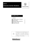
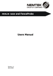
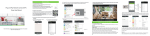
3. Product Description
Description and Function
Board Lens Type
KNC-HDi47 Installation Guide
Table of Contents
Pinhole Lens Type
➎
I mp o rtan t! : This product must be used in compliance with local laws and regulations.
2. Package Contents
➍
➊
Micro SD
Reset
1. Reset Button – Press the reset switch for more than 10 seconds,
the restore the camera to the function default settings.
2. Service Video Connector – Outputs video to the monitor.
3. Status LED
4. MIC Hole
5. Micro SD Card Socket.
6. NTSC / PAL slide Switch.
7. Power Input(DC12V) – Connects to DC 12V power.
8. Network Connector –
➐
The Network Camera connects to the network via a standard
network cable, and automatically detects the speed of the local network segment
(10BaseT/100BaseTX Ethernet). PoE Supported
PAL
1. Check the package contents against the list below.
2. Read the Product description.
3. Install the hardware.
4. Set an IP address.
5. Set the admin and user ID and password. (see User’s Manual)
➏ ➌
NTSC
Installation Steps
➊
➋
SERVICE
VIDEO OUT
IP Dome Camera Installation Guide
This installation guide provides instructions for installing the Network Camera on your
network. For all other aspects of using the product, please see the User’s Manual,
available on the CD included in this package.
PAL
1. Introduction
NTSC
➍
➎
SERVICE
VIDEO OUT
1. INTRODUCTION
2. PACKAGE CONTENTS
3. PRODUCT DESCRIPTION
4. HARDWARE INSTALLATION
5. IP ADDRESS ASSIGNMENT
6. PRODUCT SPECIFICATIONS
➋
Micro SD
Megapixel Network Camera
Reset
M175-HDi47-001
➏ ➌
➑
4. Hardware Installation
IP camera are designed to be installed using a template as shown below.
Camera Mounting Position
Tapping Screw:
ø3 x 8(2ea)
* Option
Machine Screw: ❶
M2.6 x 3.5(2ea)
❶
Network Camera
Mounting Bracket
PoE B'D Cable
Connection
Software CD
Video Output Test Cable
Installation Guide
Screws
CAUTION !
Please start installing
in the order shown.
1. Connect the camera to the network using a UTP cable (CAT.5), Power can be supplied via the network cable (PoE)
2. Connect DC 12V to the power terminal. This is not necessary if the Network Camera is connected to a PoE hub or midspan.
3. Check that the indicator LEDs indicates the correct conditions.
4. Connect the analog monitor to the service video connector for adjusting focus, then press and quickly release the reset
switch for focus assistant mode. Then you can select normal view or focus view mode using the reset switch.
Caution: When you use focus assistant mode, “Focus View” mode is recommended for more exact focus.
Caution: Focus assistant mode will be automatically exited after 3 minutes for normal operation.
5. IP Address Assignment
To make it accessible on the network, the Network Camera must be assigned an IP address.
Note:
• A network DHCP server is optional.
• The Network Camera has the default IP address 192.168.0.123.
• If IP assignment fails, check that there is no firewall blocking its operation and check that the Network
Camera and your computer's IP are located on the same subnet.
7. After installing the Web View ActiveX Control, a Login
page will be displayed. Enter the user ID and password.
8. The video image displays in your browser.
Note: Default User ID and Password is
[ID: admin, Password: admin]
Assign an IP address using IP Installer
The IP installer automatically searches for and displays network devices on your network.
The application can also be used to manually assign a static IP address.
Note:
The computer running the IP installer must be on the same network segment (physical subnet) as the Network Camera.
1. Check that the Network Camera is connected to the network and that power has been supplied.
ITEM
Image Device
Lens(Unit: mm)
Minimum Illumination
Video Codec
Resolutions (H.264/MJPEG)
Video
Video Streaming
Image Settings
Audio /
Micro SD
4. Click the “Set” button to save the configuration.
Network
Accessing the Network Camera
Supported Protocols
Power
1. Start your browser(when you first run ActiveX to install, run an “IE as Administrator” on Windows or Vista).
2. Enter the IP address or host name of the
3. If you are accessing the Network Camera for the first time, you will
Network Camera in the Address field of your browser.
see the following warning message as shown below.
Audio Code
Audio Input
Micro SD / SDHC
Security
General
Interfaces
Operating Conditions
Storage Conditions
Conformity
DESCRIPTION
2.1 Mega Pixel 1/3” SONY Progressive CMOS
Board Lens, Pinhole Lens
0.1 lux
H.264 Main Profile Motion JPEG
H.264: MAX 1920x1080 + Analog Output @ 30fps, MJPEG: MAX 1280x720 @30fps
Multi Streaming VBR / CRB (Controllable Frame Rate and Bandwidth)
Brightness, Contrast, Saturation, Sharpness, White Balance,Motion Detection, Mirror
Exposure Control, Compensation, Privacy mask, BLC, 3D DNR, D-WDR
G. 711, G.726
Built in microphone
Micro Card (Max 32GB)
Multiple user access levels with password protection, HTTPS (SSL)
IPv4, HTTP, HTTPS, TCP, RTSP, RTP, UDP, IGMP, RTCP,
SMTP, FTP, ICMP, DHCP, ARP, DNS, DDNS, HTTPS, UPnP
DC12V(±10%), Max. 240mA/ Power over Ethernet Class 3 (IEEE 802.3af)
RJ-45 for Ethernet 10baseT/100baseTX with PoE
3.5mm Power Input: DC 12V, connector for Service Video
SD Card Socket, NTSC / PAL Toggle Switch
Temperature: - 10°C ~ +50°C(14°F~122°F), Humidity MAX. 80% RH(non-condensing)
Temperature: - 20°C ~ +60°C(-4°F~140°F), Humidity MAX. 90% RH(non-condensing)
CE, FCC
Dimensions(Unit:mm)
Approx. 38
47.5
6. If a Windows Security Alert pop-up appears, click “Unblo
Approx. 28.3
47.5
PAL
Micro SD
Reset
Ø2.8
NTSC
47.5
SERVICE
VIDEO OUT
ck”.
5.5
28.3
Pinhole Lens type
51.6
5. Click “Install” to install the Web Viewer.
PAL
Reset
NTSC
51.6
5.5
28.3
SERVICE
VIDEO OUT
Board Lens type
47.5
4. Click the warning message and select “Install ActiveX Control…”.
Micro SD
i. Dynamic – Assign a dynamic IP address automatically from the DHCP server on your network.
ii. Static – Assign a static IP address manually.
iii. Port – Enter the HTTP port the Network Camera will use. The default setting is 80. Alternatively,
any port in the range 1024-65535 may be used, but check first with your
system administrator before changing the default setting.
E. Network Settings
i. Subnet Mask – Specify the mask for the subnet the Network Camera is located on.
ii. Gateway – Specify the IP address of the default router (gateway) used for connecting devices
attached to different networks and network segments.
iii. Pri. DNS – Enter the IP address of the primary DNS server. This server provides the
translation of host names to IP addresses on your network.
iv. Sec. DNS – Specify the IP address of the secondary DNS server. This will be used if the primary DNS server is unavailable.
6. Product Specifications
Ø14
2. Start NetCAM installer.
3. When the Network Camera is displayed as shown above, select the unit that needs to be assigned an IP.
A. Refresh Device List – Rescan local network to find the Network Camera.
B. Authenticate – Enter the administrator ID and password.
* Default User ID and Password is [ID: admin, Password: admin]
C. Host Name – Enter the Host Name of the Network Camera.
D. IP Settings
Note: To view streaming video in Microsoft Internet
Explorer, you must set your browser to allow the “Web
Viewer” to be installed on your computer. This ActiveX
component is installed the first time a video stream is
accessed.