1
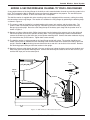
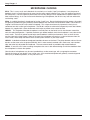
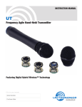
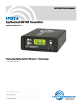
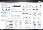
Portable Wireless Sound System
L o n g
R a n g e r
FAST
CHARGE
PORTABLE WIRELESS SOUND SYSTEM
OPERATING INSTRUCTIONS
and trouble-shooting guide
LECTROSONICS, INC.
Rio Rancho, NM, USA
Rio Rancho, NM – USA
1
Long Ranger 4
INTRODUCTION
Thank you for selecting the Long Ranger portable wireless sound system. This
unique design combines a rechargeable power supply, a high-power amplifier and
loudspeaker, and high quality VHF wireless microphone into a single compact
assembly. The design has evolved with numerous refinements since its first predecessor was introduced in the early 1980’s to serve public address applications
indoors and outdoors, with the ruggedness and reliability needed for professional
use.
A single Long Ranger provides enough output power to cover surprisingly large
outdoor areas as a stand-alone unit. Versatile options and accessories expand the
use of the Long Ranger to handle unusual coverage areas with the addition of
external loudspeakers. Optional accessories also include an additional wireless
microphone, hard-wired microphone, tape recorder, CD player, etc. Two Long
Ranger systems can be interconnected with a single cable to allow multiple microphones and other audio sources to use both systems simultaneously, operating
together as though they are a single sound system.
TABLE OF CONTENTS
INTRODUCTION ...................................................................................................... 2
GENERAL TECHNICAL DESCRIPTION ................................................................ 3
RECHARGEABLE BATTERIES AND EXTERNAL POWER SOURCES .............. 3
CONTROLS AND FUNCTIONS .............................................................................. 4
CONTROL PANEL ............................................................................................. 4
FRONT PANEL ................................................................................................... 5
SYSTEM SETUP RULES ......................................................................................... 6
INITIAL EQUIPMENT ADJUSTMENTS .................................................................. 6
USING ADDITIONAL SPEAKERS .......................................................................... 8
ADDING A SECOND WIRELESS CHANNEL TO YOUR LONG RANGER .......... 9
INITIAL ADJUSTMENTS TO THE ADD-ON RECEIVER SYSTEM .................... 10
SPECIAL NOTE TO DUAL-CHANNEL USERS .................................................... 10
MULTIPLE LONG RANGER SYSTEMS ............................................................... 11
MICROPHONE CHOICES ..................................................................................... 12
ACCESSORIES AND REPLACEMENT PARTS ................................................... 13
SPECIFICATIONS .................................................................................................. 13
TROUBLESHOOTING ............................................................................................ 14
SERVICE AND REPAIR ......................................................................................... 15
RETURNING UNITS FOR REPAIR ....................................................................... 15
WARRANTY ............................................................................................. Back cover
2
LECTROSONICS, INC.
Portable Wireless Sound System
GENERAL TECHNICAL DESCRIPTION
The standard Long Ranger Portable Wireless Sound System consists of a combination wireless receiver/amplifier/
speaker with a rechargeable battery pack, a belt-pack or plug-on transmitter and a microphone. Optional microphones, extension speakers and add-on equipment for a second wireless channel are available.
The Long Ranger features a VHF wireless microphone system with a transmitter-to-receiver operating range of up to
750 feet. The receiver is designed for high selectivity to prevent interference from other transmitted radio signals.
The system is designed and constructed for rigorous portable use with the antenna integrated into the horn speaker
to eliminate damage.
The Long Ranger will operate from 8 to 12 hours from the “on-board” rechargeable battery pack before recharging is
necessary. The actual operating time is dependent upon the type of usage....intermittent or continuous. The unit can
also be operated from an external 12 Volt DC source or an AC wall outlet.
The amplifier produces 33 Watts, RMS, into the 8 Ohm horn speaker. The sound output will cover an area the size of
a football field under average outdoor conditions. Several Long Rangers can be easily connected together to provide
even greater area coverage.
RECHARGEABLE BATTERIES AND EXTERNAL POWER SOURCES
The built-in battery pack in the Long Ranger is charged by plugging the DCR15/2AU charger into the jack labeled
DCR15/2AU CHARGER on the control panel. Connect the charger into a standard 110 or 220 Volt AC outlet. (The
DCR15/2AU charger can be operated from 110/220V, 50/60Hz.) The green lamp beneath the jack will light as long
as the batteries are charging. When the batteries are almost completely charged the green charging light will go out.
You may leave the charger plugged in after the green light has gone out with no danger of damage to the system. In
fact, we recommend charging the system whenever it is not in use, then the system will always be “ready to go”.
The DCR15/2AU charger can charge the batteries in as little as 2 1/2 hours. If the unit is completely run down, it may
require as much as 6 hours to fully charge the batteries. Leave the charger plugged in at least until the green lamp
below the CHARGER jack goes out.
(NOTE: In the case of severely discharged batteries (this can happen if the Long Ranger has been
left on constantly for several months), it may be necessary to charge the unit for a much longer time.
Up to 10 days charge time is not uncommon in these circumstances.)
The DCR15/2A charger is capable of charging the batteries and running the Long Ranger in normal operation at the
same time. The time required to fully recharge that batteries will be longer if the unit is being used while charging the
battery pack.
!! CAUTION !!
USE ONLY THE SUPPLIED DCR15/2A CHARGER
DO NOT USE THE OLDER CH40 CHARGER IN THE NEW LONG RANGER 4. THE CH40
WILL NOT CHARGE THE BATTERIES IN THE LONG RANGER 4 AND WILL BE DAMAGED IF USED.
The Long Ranger can be operated from an external 12 Volt DC source such as an automobile battery or, most
commonly, from the cigarette lighter receptacle in your vehicle. To use an external power source it must be connected into the 12V DC POWER INPUT jack on the Long Ranger front panel. CAUTION--Make sure you comply
with the polarity markings on the jack. The correct plug for making the connection is a Radio Shack 274-1567 size K
coaxial DC power plug. Radio Shack also stocks cigarette lighter plugs (with built-in fuse) and cords to construct a
suitable assembly.
Rio Rancho, NM – USA
3
Long Ranger 4
CONTROLS AND FUNCTIONS
CONTROL PANEL
WIRELESS MICROPHONE VOLUME
Turns unit power on and off and also functions as the volume control for the internal wireless receiver.
POWER
A red LED that lights when unit power is on.
RF
A green LED that lights when the companion transmitter is turned on and there is sufficient signal for good system
operation. Internal circuits monitor both signal level and interference levels and decide if the transmitted signal is
strong and “clean” enough for satisfactory operation. If not, the green RF LED will go out and the receiver will mute
the audio (“squelch”), turning off the sound output. This action is automatic and requires no user adjustment.
MOD LEVEL
The red and green MOD LEVEL LEDs continuously indicate the modulation level (audio level) of the received signal
from the transmitter and are used when making initial adjustments to the transmitter.
MIC
This connector is a standard 1/4" phone jack and is used for plugging in the cord from a low impedance dynamic
microphone.
LINE
This mini jack is used for connecting high level, high impedance outputs from tape decks or other amplifiers. It also
may be used for connecting the “earphone” output from portable cassette players.
AUXILIARY INPUT VOLUME
Adjusts the volume of the MIC and LINE inputs.
AUX IN/OUT
An RCA phono jack that functions both as a line level input and line level output. This “omnibus” jack is primarily
used for interconnecting several Long Rangers together for simultaneous operation. This jack can also be used with
a tape deck to either record from or play back into the Long Ranger. When used with a tape deck or other audio
source, the sound output level must be controlled by the volume control on the tape deck since there is no volume
control on the Long Ranger for the AUX IN/OUT jack. When an external device is connected to this jack, the loudness of the Long Ranger will usually be reduced.
DCR15/2AU CHARGER
A special jack used for connecting the charger when charging the battery pack. The green LED located under the
jack lights when the batteries are charging. This LED automatically goes out when the batteries are almost fully
charged.
12V DC OUTPUT
A special jack used to supply power to the Add-On receiver when that option is installed.
4
LECTROSONICS, INC.
Portable Wireless Sound System
FRONT PANEL
12V DC EXT POWER
A special jack used to connect an external 12 Volt DC source to the unit to substitute for the “on-board” battery pack.
It is most commonly used for connecting the Long Ranger to a vehicle cigarette lighter or 12V DC auxiliary receptacle. When an external power source is connected to this jack, the on-board battery pack is automatically disconnected. Connectors and power supply cables are available from electronics parts suppliers such as Radio Shack.
EXTERNAL 8 OHM SPEAKERS
Two jacks which are used to connect external 8 ohm loudspeakers such as the Lectrosonics H300 re-entrant horn.
This jack can also be used to power other brands of loudspeakers, but be sure that the speaker has a rated impedance of 8 ohms. The left-hand jack disconnects the built-in horn when the plug is inserted. The right-hand jack will
operate the internal horn along with the external speaker. The efficiency of different makes and models of speakers
varies significantly. Even though two different speakers are both rated at 8 ohms, their loudness could be quite a bit
different. The other specification to compare when considering the use of another speaker is the efficiency rating.
The horn built into the Long Ranger is rated at 107 dB SPL (sound pressure level) at one meter with a one watt input.
Check this specification on the speaker you are considering. A speaker with a lower “dB’ number will not be as loud
as the horn built into the Long Ranger.
L o n g
R a n g e r
AUX IN/OUT
12V DC
OUTPUT
WIRELESS
MICROPHONE
VOLUME
AUXILIARY
INPUT
VOLUME
USE
ONLY
L o n g
R a n g e r
CHARGE
LECTROSONICS
PROFESSIONAL WIRELESS
FAST CHARGE
CIRCUITRY
MIC
RF
FAST
EXTERNAL
8 OHM SPEAKERS
LINE
12V DC
MOD
LEVEL
OFF
DCR15/2AU
CHARGER
EXT POWER
POWER
CHARGE UNTIL
LAMP GOES OUT
DISCONNECTS
MAIN HORN
Figure 1 - Long Ranger 4 Control Panel
Rio Rancho, NM – USA
OPERATES w/
MAIN HORN
Figure 2 - Long Ranger 4 Front Panel
5
Long Ranger 4
SYSTEM SETUP RULES
This section includes some basic rules that will ensure trouble-free operation of your Long Ranger system:
1) Make sure the transmitter battery is good, or better yet, new.
2) Charge up the battery pack in the Long Ranger fully before you use the system. Charge until the green charging
lamp underneath the CHARGER jack on the Long Ranger control panel goes out.
3) Set up the system so that the Long Ranger is as far from large metal surfaces as possible. Metal surfaces under
the unit (such as pickup truck cabs or a car top) are generally no problem but large metal surfaces alongside the
Long Ranger may interfere with wireless reception.
4) If you have more than one transmitter on the same frequency, turn on only one transmitter at a time. You cannot
use two transmitters at the same time with a single Long Ranger. You will need to “alternate” back and forth
between the transmitters. Failure to do so will result in an obnoxious whining sound from the system, and the
audio will probably not be understandable. “Add-on” wireless mic systems are available separately to permit
operation of two transmitters simultaneously through a single Long Ranger.
5) Use the minimum volume that will enable everyone to hear. It doesn’t have to be loud to be heard.
6) Always turn the power off before connecting or disconnecting external speakers.
7) The Long Ranger should be elevated for best coverage. The unit should ideally be at least 2 feet higher than the
audience. For example, with an audience standing on flat ground, the number of people that can hear clearly will
double if you raise the unit from 5 feet above the ground to 7 feet above the ground.
8) During actual operation the Long Ranger should be located at least 20 feet away from the person using the
microphone and aimed so that the sound from the speaker is directed toward the audience and away from the
microphone. This will reduce feedback problems. “Feedback” is a loud squealing sound coming from the speaker
when the volume is too high or the microphone is too close to the Long Ranger. Feedback is generally much
more of a problem when using lavalier (lapel) type microphones. The headset models are recommended for use
with the Long Ranger system since they place the microphone pickup much closer to your mouth, which increases the loudness of the Long Ranger before feedback occurs.
INITIAL EQUIPMENT ADJUSTMENTS
This section covers the initial adjustments to the transmitter and Long Ranger that must be made before the system
is placed into operation. The step-by-step procedures are listed in the order in which they should be performed:
1) Turn Long Ranger power on - The POWER lamp lights.
2) Rotate both volume controls counter-clockwise to their minimum settings.
3) Position yourself behind the Long Ranger so that the sound from the speaker will be directed away from the
microphone.
4) Plug your microphone into the transmitter. Rotate the plug clockwise to make sure the connection is locked.
5) Turn the transmitter power on and verify that the red lamp on it lights. If the lamp is very dim or does not light,
replace the battery.
6) Observe that the green RF lamp on the Long Ranger control panel is lighted. This verifies that the unit is receiving a usable signal from the transmitter.
7) Position the microphone on yourself (or other user) in the location it will be during actual operation. If you are
using the single-band or dual-band headset microphone, turn the white knob on the headset fully clockwise
(maximum). The HM162 over-ear microphone should be positioned so that the pickup element is just to the left of
the mouth, so that breath pops do not strike the capsule. Lavalier microphones should be positioned high on the
chest or collar, as close to the mouth as possible to minimize the possibility of “feedback.”
6
LECTROSONICS, INC.
Portable Wireless Sound System
8) A small screwdriver is supplied with the transmitter. The screwdriver is used to adjust the audio gain of the
transmitter to match your microphone and your voice. The adjustment is made while observing the MOD LEVEL
lamps on the Long Ranger control panel:
a) Speak at the voice level you will be using during actual operation.
b) While speaking, adjust the transmitter gain with the screwdriver until the green MOD LEVEL lamp on the Long
Ranger control panel is lighted or flickers and the red MOD LEVEL lamp blinks on the loudest words. Raise
and lower your voice while observing the lamps. The red lamp should blink occasionally.
9) Now adjust the WIRELESS MICROPHONE VOLUME control on the control panel to a level where everyone can
hear. You will probably have to do this in several steps. If you attempt to adjust the volume yourself while standing and just behind the unit, you will likely have a “feedback” problem. It is convenient to have another person
adjust the volume while you transmit from a position 20 feet or more behind the unit.
REMEMBER--the transmitter gain control (the screwdriver adjustment) is used only to adjust for proper MOD LEVEL
lamp indications. DO NOT use it to adjust the output volume of the Long Ranger speaker. Different voices and
different microphones will usually require readjustment of the transmitter gain control, so check the adjustment
frequently. If several different people will be using the system and there is not time to make the adjustment for each
individual, adjust it for the loudest voice.
AUX
12V DC
OUTPUT
WIRELESS
MICROPHONE
VOLUME
While speaking, Adjust the
transmitter as you observe
the LEDs on the receiver.
USE
ONLY
RF
MOD
LEVEL
OFF
DCR1
CHAR
POWER
M175 Transmitter
GREEN LED
RED LED
Figure 3 - Transmitter Gain Adjustment
Rio Rancho, NM – USA
7
Long Ranger 4
USING ADDITIONAL SPEAKERS
CAUTION!
ALWAYS TURN THE LONG RANGER POWER OFF
BEFORE PLUGGING IN OR UNPLUGGING EXTERNAL SPEAKERS
In some cases, the proper coverage of an audience requires a second speaker. The optional H300 is identical to the
Long Ranger speaker and can be used to spread the sound over a broader area.
The output jacks for external speakers are located on the Long Ranger front panel. The left and right jacks operate
differently. The right jack does not disconnect the built-in speaker when a plug is inserted into it. This means that the
built-in speaker and the external speaker will both operate together. The left output jack disconnects the built-in
speaker and powers only the external speaker. Internal circuits and switching networks keep track of the number of
speakers hooked up and select the amplifier impedance so that the full power of the amplifier is always available. It
is important that you use only an 8 Ohm speaker in these jacks. If you are not using Lectrosonics extension speakers, check the speaker for the proper rating before connecting to the Long Ranger.
The efficiency of different makes and models of speakers varies significantly. Even though two different speakers are
both rated at 8 ohms, their loudness could be quite a bit different. The other specification to compare when considering the use of another speaker is the efficiency rating. The horn built into the Long Ranger is rated at 107 dB SPL
(sound pressure level) at one meter with a one watt input. Check this specification on the speaker you are considering. A speaker with a lower “dB’ number will not be as loud as the horn built into the Long Ranger.
The H300 speaker is typically used in conjunction with the built-in speaker to increase the sound coverage area.
This is done by plugging the H300 into the right speaker jack, so that both speakers will work together. In a large
area, such as a football field, try to arrange the speakers so that the listeners are not in the direct sound field of both
speakers. If a listener can hear two speakers located at different distances, a distracting “echo effect” occurs. Put
the speakers close to one another in a central location and aim them in opposite directions to broaden the coverage
pattern.
When using two external speakers simultaneously, the built-in speaker will be automatically disconnected to prevent
overload of the amplifier since a plug has been inserted into the left-hand jack.
8
LECTROSONICS, INC.
Portable Wireless Sound System
ADDING A SECOND WIRELESS CHANNEL TO YOUR LONG RANGER
A very popular feature of the Long Ranger is the ability to add a second wireless channel to an existing system in the
field. The Lectrosonics Add-On Receiver system was expressly designed for that purpose. The standard system
consists of an Add-On receiver, an M175 transmitter and a microphone.
The Add-On receiver is supplied with velcro attaching strips and is equipped with the necessary cabling for making
the connections to the Long Ranger. The receiver is installed on the Long Ranger by performing the following steps
as shown in Figure 4:
1) The antenna cable for the Add-On is packed together with screws, lock washers and the velcro strips. The
antenna cable is terminated with two ring lugs. Feed the lug end of this cable through the hole in the Long
Ranger rear panel upright. Dress the cable along the top of the battery pack along with the speaker wires as
shown in Figure 4.
2) Remove and discard the two black Phillips head screws from the bottom of the antenna strip on the right-hand
side of the speaker and from the speaker mounting block. Using the supplied bright screws and lockwashers,
connect the shield ring lug (the black wire) to the speaker mounting block. Connect the center conductor ring lug
(the clear/white wire) to the antenna. Tighten both screws securely.
3) The Add-On receiver is to be mounted on the Long Ranger upright with velcro. The receiver should be positioned, control panel up, between the horn mounting screw and the screw which secures the battery pack to the
upright. Remove the paper backing from one side of the velcro and affix it to the back of the receiver. Remove
the remaining paper backing and affix the receiver to the upright.
4) Route the antenna cable through the hole in the rear upright panel, above the battery pack so that the black and
white wires reach the speaker mounting block. Connect the remaining two cables to the 12V DC OUTPUT jack
and the LINE input jack on the control panel.
BLACK
LEAD
Add-On
Receiver
WHITE
LEAD
ANTENNA
BLACK
LEAD
BATTERY
SPEAKER
MOUNTING
BLOCK
Figure 4 - Add-on Receiver Antenna Connections
Rio Rancho, NM – USA
9
Long Ranger 4
INITIAL ADJUSTMENTS TO THE ADD-ON RECEIVER SYSTEM
1) Set up the Long Ranger system according to the Initial Equipment Adjustments on page 6.
2) Leave the Long Ranger power turned on. Set both volume controls on the Long Ranger control panel to minimum.
3) Turn the Add-On receiver power switch to “ON.” Check to see that the power lamp comes on.
4) Plug the microphone into the transmitter that is on the same frequency as the Add-On receiver. The plug on the
microphone is a twist-lock connector. Make sure there is a good connection. If you are using the headset microphone, turn the white level control knob on the headset fully clockwise (maximum).
5) Install the 9 Volt battery into the transmitter, turn the transmitter on and make sure the red LED on the transmitter
glows brightly.
6) Check to see that the green “RF” LED on the Add-On receiver glows steadily. This verifies that the receiver is
picking up a good radio signal from the transmitter.
7) This is the most important step in the set up procedure. Place the microphone in the exact position where
you will be using it. Speak at the same voice level that you will use during actual operation. While you speak, use
the supplied screwdriver to adjust the gain control on the transmitter side panel (see page 7) while you observe
the MODULATION LEDs on the Add-On receiver front panel. The green LEVEL lamp should flicker or stay lit as
you speak. The red LIMIT lamp should blink only on louder words.
8) Adjust the AUXILIARY INPUT VOLUME control on the Long Ranger control panel for the necessary loudness. If
the transmitter gain controls have been correctly set on both the Longer Ranger 4 and the Add-On system, both
volume control knobs on the Longer Ranger 4 panel will be in about the same position for equal loudness on both
systems. It is not unusual, however, that one of the volume controls may need to be set higher or lower than the
other one in normal use. Adjust the controls separately for adequate sound levels for each microphone.
SPECIAL NOTE TO DUAL CHANNEL USERS
If you are only using one of the two wireless systems, it is best to use the wireless system built into the Long Ranger
and leave the Add-On receiver turned off. This will prevent unwanted noise, hiss or static that could occur in the
unused receiver from entering the Long Ranger.
If it is necessary to use the Add-On receiver by itself, turn the WIRELESS MICROPHONE VOLUME control knob on
the Long Ranger control panel to minimum. Then set the AUXILIARY INPUT VOLUME for the necessary loudness of
the Add-On system.
10
LECTROSONICS, INC.
Portable Wireless Sound System
MULTIPLE LONG RANGER SYSTEMS
A unique use of the AUX IN/OUT jack is for connecting two Long Ranger systems together for simultaneous use.
When connected in this manner, they will operate like a single system. It is best to use two different Long Ranger
units that operate on different frequencies. Any input on either Long Ranger will appear at both speakers. If the
Long Ranger systems are on the same frequency, only one transmitter can be used at any given moment.
Second channel (add-on) wireless systems on either (or both) Long Ranger systems will work fine, as long as they
are all on different frequencies. Each wireless microphone will have its own volume control. The built-in wireless in
each Long Ranger will be controlled by the left-hand knob on the matching unit. The volume of each add-on wireless
system will be controlled by the right-hand knob on the matching unit. All sound from all wireless microphones will
appear on all loudspeakers, both built-in or external.
Connect the Long Ranger systems together with a standard RCA (phono) patch cord, male plug to male plug. It is
best to use cords 10 to 12 ft. in length (or less) to minimize noise that can occur with long cables.
AUX IN/OUT
Connect two
Long Rangers
together using
the AUX IN/OUT
jacks.
AUX IN/OUT
Figure 5 - Connecting Two Long Ranger Systems
If any of the Long Rangers or add-on wireless system are on the same frequency, only one transmitter can be used
at a time on that frequency. REMEMBER that if two transmitters on the same frequency are turned on at the same
time, the receiver will not receive either of them properly. You will need to “alternate” the use of the transmitters.
The INITIAL EQUIPMENT ADJUSTMENTS (see page 6) should be performed on each system individually before
the AUX IN/OUT interconnection is made. After the units are connected together, adjust the volume on each Long
Ranger for the loudness level needed.
Rio Rancho, NM – USA
11
Long Ranger 4
MICROPHONE CHOICES
M119 - This is a very small, omni-directional mic used only as a lavalier (“lapel”) microphone. It may be prone to
feedback since it is usually placed so far away from the users mouth; however it has a very flat response and excellent tone quality. The M119 generally works best with the Long Ranger and an ES300 column speaker indoors at a
lower volume setting. As is true of most omni-directional type microphones, the M119 is very free from wind noise
and clothing “rattle”.
M140 - A cardioid (directional) microphone for lavalier (“lapel”) use. Due to the directional pickup pattern, this model
will generally provide more gain (loudness) before feedback than the M119 omni-directional model. The M140 has a
“brighter” sound than the M119 (the treble is boosted). This crisper sound normally improves the clarity that is
sometimes lost with lavalier type microphones. The M140 is subject to wind noise and generally works best indoors,
however it is supplied with a foam windscreen which helps to prevent noise caused by wind.
HM142V - This single-band headset microphone is normally worn on the head, but can also be worn around the
neck for hands-free operation. It provides maximum gain before feedback since the microphone is very close to the
user’s mouth. The built-in volume control helps control feedback in difficult environments, such as when the user
must be close to the Long Ranger. Worn on the head, the microphone will remain at a constant distance from the
user’s mouth, which keeps the volume of the sound system constant as your head moves.
HM152V - A double-band headset microphone intended to be worn on the head. The pickup element and tonal characteristics are the same as the single-band HM142V, but it is more securely mounted and in most cases, more comfortable, due to the fully adjustable dual headband. The same volume control is provided to help control feedback.
HM162 - A “over the ears” noise cancelling microphone that uses a dual-element design to minimize feedback when
the microphone is close to the speaker.
Other brands of microphones may be used, provided they are the correct type, with an appropriate connector.
Consult the factory or your dealer if you are not sure. A mis-matched microphone will generally cause background
noise (hiss) or feedback problems, or may not work at all.
12
LECTROSONICS, INC.
Portable Wireless Sound System
ACCESSORIES AND REPLACEMENT PARTS
DCR15/2AU
Battery Charger
Replacement
HM142V
Single headband
With locking micro plug for M175 series transmitters.
HM152V
Double Headband
Double adjustable headband. With micro plug
Headset Microphone for M175 series transmitters.
HM162
“Over ears” Headset
A comfortable headworn design that places the microphone pickup element
close to the mouth, using a dual-element, noise cancelling technique to
minimize feedback.
MC-16C
Microphone Cord
16 ft. coil cord (1/4" male to male) for M121S
MC-44
Microphone Cord
1/4" male to locking micro male; adapts M121S to M175
MM-36
Patch Cord
36" RCA (male to male) For interconnecting AUX IN/OUT jacks.
RK-51
Wind Screen
For M121S microphone
RK-119
Wind Screen
For M119 and M140 microphones
RK-142
Wind Screen
HM142V and HM152V headset microphones
CCPRO
Carrying Case
Molded, pre-cut foam lined
SS-5
Tripod Stand
2-section legs, riser column; 59" max. height
SPECIFICATIONS
Operating frequency:
169 to 186 MHz
Audio power output:
33 Watts, RMS, into 8 Ohms
Distortion:
less than 1%
Amplifier freq. response:
100 Hz to 15 kHz; +0, -3 dB (Omnibus jack input to external
speaker jack output.)
Overall freq. response:
200 Hz to 3 kHz; +0/-3dB (Wireless input to horn output.)
Max. audio output (SPL):
Over 120 dB at 3 feet
FM deviation:
±15kHz
Wireless operating range:
Up to 750 feet
RF signal-to-noise ratio:
96dB, A weighted
Speaker:
6" x 12" re-entrant horn
Weight:
16 lbs.
Dimensions:
15" high, 6 3/4" wide, 9 3/4" deep
Specifications subject to change without notice.
Rio Rancho, NM – USA
13
Long Ranger 4
TROUBLESHOOTING
SYMPTOM
POSSIBLE CAUSE
Long Ranger red POWER lamp not on
or dim
1) WIRELESS MICROPHONE VOLUME
control in OFF position
2) Batteries completely discharged
4) Battery terminals disconnected or loose
Long Ranger green RF lamp not on
1) Transmitter not on
2) Dead battery in transmitter
3) Transmitter and receiver not on same frequency
Long Ranger red POWER lamp and
green RF lamp on, but no sound
A) MOD LEVEL lamps dark
1) Transmitter is not getting an audio signal. Defective mic or cable.
2) Transmitter gain control set much too low
B) MOD LEVEL lamps indicating
1) WIRELESS MICROPHONE VOLUME control normal turned
completely down
2) Defective horn or speaker
System operation normal except
for high hiss or hum level
A) Green MOD LEVEL lamp
dark or barely flickers
1) Transmitter gain control set too low
2) Headset volume (white knob) turned down
B) MOD LEVEL lamps appear normal
1) Noisy microphone or mic cable? To verify, replace with
known good microphone.
2) Hiss in device connected to Long Ranger? Turn off
the device. If hiss stops, problem is in the device.
If hiss remains, the problem is in the Long Ranger.
3) Hiss in the Long Ranger can be caused by poorly shielded
computers, phone systems, older electronic organs, etc. Try
turning off nearby suspect equipment.
System operation normal except
for “feedback” and/or red MOD LEVEL
lamp on or blinking frequently
1) Transmitter gain set too high.
2) Output level of device connected is too high
Weak, distorted sound. Power
lamp flickers. “Motorboating”
(rapid popping sound.)
Batteries very low. Recharge.
14
LECTROSONICS, INC.
Portable Wireless Sound System
SERVICE AND REPAIR
If your system malfunctions, you should attempt to correct or isolate the trouble before concluding that the equipment needs repair. Make sure you have followed the setup procedure and operating instructions. Check out the
interconnecting cords and then go through the TROUBLE SHOOTING section in the manual
We strongly recommend that you do not try to repair the equipment yourself and do not have the local repair shop
attempt anything other than the simplest repair. If the repair is more complicated than a broken wire or loose
connection, send the unit to the factory for repair and service. Don’t attempt to adjust any controls inside the units.
Once set at the factory, the various controls and trimmers do not drift with age or vibration and never require
readjustment. There are no adjustments inside that will make a malfunctioning unit start working.
LECTROSONICS’ service department is equipped and staffed to quickly repair your equipment. In warranty repairs
are made at no charge in accordance with the terms of the warranty. Out of warranty repairs are charged at a
modest flat rate plus parts and shipping. Since it takes almost as much time and effort to determine what is wrong
as it does to make the repair, there is a charge for an exact quotation. We will be happy to quote approximate
charges by phone for out of warranty repairs.
RETURNING UNITS FOR REPAIR
You will save yourself time and trouble if you will follow the steps below:
A. DO NOT return equipment to the factory for repair without first contacting us by letter or by phone. We need to
know the nature of the problem, the model number and the serial number of the equipment. We also need a phone
number where you can be reached 8 am to 4 pm (Mountain Standard Time).
B. After receiving your request, we will issue you a return authorization number (R.A.). This number will help speed
your repair through our receiving and repair departments. The return authorization number must be clearly shown
on the outside of the shipping container.
C. Pack the equipment carefully and ship to us, shipping costs prepaid. If necessary, we can provide you with the
proper packing materials. UPS is usually the best way to ship the units. Heavy units should be “double-boxed” for
safe transport.
D. We also strongly recommend that you insure the equipment, since we cannot be responsible for loss of or
damage to equipment that you ship. Of course, we insure the equipment when we ship it back to you.
Mailing address:
Lectrosonics, Inc.
PO Box 15900
Rio Rancho, NM 87174
USA
Shipping address:
Lectrosonics, Inc.
581 Laser Rd.
Rio Rancho, NM 87124
USA
World Wide Web: http://www.lectrosonics.com
Telephones:
Regular: (505) 892-4501
Toll Free (800) 821-1121
FAX:
(505) 892-6243
Email: [email protected]
Rio Rancho, NM – USA
15
LIMITEDONE
ONE YEAR
LIMITED
YEARWARRANTY
WARRANTY
The equipment is warranted for one year from date of purchase against defects in
materials or workmanship provided it was purchased from an authorized dealer. This
warranty does not cover equipment which has been abused or damaged by careless
handling or shipping. This warranty does not apply to used or demonstrator equipment.
Should any defect develop, Lectrosonics, Inc. will, at our option, repair or replace any
defective parts without charge for either parts or labor. If Lectrosonics, Inc. cannot
correct the defect in your equipment, it will be replaced at no charge with a similar new
item. Lectrosonics, Inc. will pay for the cost of returning your equipment to you.
This warranty applies only to items returned to Lectrosonics, Inc. or an authorized
dealer, shipping costs prepaid, within one year from the date of purchase.
This Limited Warranty is governed by the laws of the State of New Mexico. It states the
entire liablility of Lectrosonics Inc. and the entire remedy of the purchaser for any
breach of warranty as outlined above. NEITHER LECTROSONICS, INC. NOR
ANYONE INVOLVED IN THE PRODUCTION OR DELIVERY OF THE EQUIPMENT
SHALL BE LIABLE FOR ANY INDIRECT, SPECIAL, PUNITIVE, CONSEQUENTIAL,
OR INCIDENTAL DAMAGES ARISING OUT OF THE USE OR INABILITY TO USE
THIS EQUIPMENT EVEN IF LECTROSONICS, INC. HAS BEEN ADVISED OF THE
POSSIBILITY OF SUCH DAMAGES. IN NO EVENT SHALL THE LIABILITY OF
LECTROSONICS, INC. EXCEED THE PURCHASE PRICE OF ANY DEFECTIVE
EQUIPMENT.
This warranty gives you specific legal rights. You may have additional legal rights which
vary from state to state.
LECTROSONICS, INC.
581 LASER ROAD
RIO RANCHO, NM 87124 USA
http://www.lectrosonics.com
October 28, 2003