Transcript
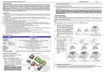
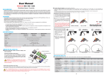
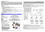
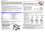
ATTENTION
Thank you for purchasing the Justock-3650 brushless motor(s) for RC cars! The high power
system can be very dangerous, so please read this manual carefully before using and follow
the operating procedures strictly. In that we have no control over the installation, use and
maintenance of this product, no liability shall be assumed nor accepted for damages, losses or
costs resulting from the use of this product. Besides, we own the right to change the product
design, appearance, functions and operational requirements without any notifications.
CAUTIONS
USER MANUAL
01 Safety Notes
Sensored Brushless Motor
3650-Sensored
ATTENTION
This product is NOT a toy and it is for use by adults and teens over 14 only, so please keep it out of children’s
reach. Please keep the following points in mind; otherwise it may damage the product and cause property
loss and physical injuries to users.
• Never leave this product unsupervised when it is powered on. If any problem occurs, the product may cause a fire
and jeopardize peripheral devices.
• Please check wire sequences between the ESC & the motor carefully before the connection, to avoid any possible mistakes.
• Please insure all the wires and interconnecting pieces are well insulated before the connection, as short circuits may
damage the product.
• Never allow water, oil, fuel or other conducting liquids to get inside this product or other electronic parts, as these
liquids may contain harmful minerals for electrical circuits. If that really happens, please turn off the device
immediately, and then clear and blow-dry it carefully.
• Please read through manuals of each power equipment (like ESC, motor, battery, etc) and chassis to ensure the
power system configuration is rational before the use, as the incorrect power system configuration may result in
overload and eventually damage the equipments.
• Prohibit the full throttle operation before the pinion installation. Under non-loaded circumstances, over-high RPM
may cause damage to the motor.
• Make sure all the parts are well connected, as misconnection or poor connection may lead to abnormal control,
damage or other unpredictable problems.
• Never let the temperature of the motor can (shell) exceeds 90°C (194°F), otherwise the motor is likely to be
damaged and (or) the rotor will be demagnetized.
02 Installation & Connection
1. To Install the Motor
1) Screws used for installation are 3mm in diameter & 5mm in length. Before mounting the motor onto the
vehicle, please ensure that all the screws are applicable to avoid damaging the motor. In general it’s ok to adopt
screws which are 3 mm in diameter and less than 8mm in length; the specific length is up to the chassis size.
2) Install the golden connectors; here it adopts the brand new method to fasten male & female connectors by
screws.
2. To Connect the Motor
1) Three power wires need to be connected to the motor, and they often differ in colors: Phase wire A is Blue,
Phase wire B is Yellow and Phase wire C is Orange. Please note the ESC mark while connecting ESC output wires
to motor power wires and ensure connections are: A-A, B-B and C-C.
2) If you are using a sensored ESC, please insure Hall-sensor wires are clean and undamaged; then connect them
in the correct direction to the sensor ports of the motor & the ESC respectively. Warning: In such a case, the
wire sequence of the ESC and the motor must strictly follow the rules of A-A, B-B and C-C. Do not change the
wires sequence.
3) While if the ESC is a sensorless one, then connect the motor and the ESC according to the above way may
cause the motor to rotate in the opposite direction, because definitions of phase (#A / #B / #C) are different
among manufacturers, at this time you only need to swap any of two wire connections.
3. Checkup
Recheck the installation and all the connections carefully before turning on the power.
03 Specifications
Model
KV
(No-load)
PN
LiPo
R. (Ω)
No-load
Current
Max.
Output
Power
C. at the
point of
M.O.P *
Justock-3650-10.5T
30408000
3500KV
0.0175
2.4A
265W
72A
Justock-3650-13.5T
30408001
2700KV
0.0275
1.7A
210W
58A
Justock-3650-17.5T
30408002
2100KV
0.0465
1.3A
150W
42A
Justock-3650-21.5T
30408003
1750KV
0.075
1.2A
110W
35A
IMPORTANT
2~3S
Dimension
(mm)
shaft *
(mm)
Outer
Diameter
35.8
Diameter
3.17
Length
52.5
Pole
Length of
Projectiong part
15
W (g)
2
Applicable
201
1:10 ,1:12 On-Road (Truggy / Drifting Car / F1 /
200
Monster) & Off-Road (Buggy / 2WD SC Truck /
Truck) STOCK / SPORT Race (choose the motor
198
base on competition rules.) Free / casual run
197
for new beginners. Rock Crawler (21.5T only)
Notes: C. at the point of M.O.P. = Current at the point the Maximum Output Power.
1) The maximum output power is the test value obtained when the voltage is 7.4V, the ESC timing is set to 0°. It is neither the maximum input power nor the rated power. The calculation formula used here is: RPM x Torque /
9550.
2) The value of the maximum output power is always lower than the value of the input power. Therefore, it’s meaningless to compare the maximum output power mentioned in the form above with the input power of
motors of other brands. Besides, values in the form above may differ from the test data of other factories because of different test benches.
3) The input current at the point of the maximum output power is useful for the load configuration and the ESC selection; here we strongly suggest users not make the load quota bigger than the “maximum output power
point”, that means please don’t make the input current larger than the current at the maximum output power point.
4) As the power of 10.5T, 13.5T, 17.5T & 21.5T motor is not big, so they are not applicable for 4WD / Monster trucks and other high weight and heavy load vehicles or games need very great power. If forcibly use them in
those conditions, perhaps they will get burnt. Hereby, we suggest users choose the 4-pole motor like XERUN-3656 when high power is needed.
04 Gear Selection (IMPORTANT!)
It is very important to select the reasonable gear ratio, as inappropriate selection may cause great loss to users. Please select
the correct gear ratio according to the following points!
1. Operating Temperature of the Motor
During the operation, the motor temperature should be lower than 90℃ (194℉). Temperatures above 90℃ will demagnetize the
magnet & may melt the coils and eventually damage the ESC (because of strong current). Therefore, the most effective way to
prevent over-heat is to select the right gear ratio.
2. Principle of Gear Selection
To avoid potential risks, caused by overheating, which may lead to ESC/motor damage or malfunction, please start with very small
pinion and check ESC & motor temperatures frequently throughout a run. This is the only way to guarantee that you are not
causing excessive heating. If Motor and the ESC temperatures remain stable and low in the running, then you can slowly increase
the pinion (with more teeth) while again monitoring the temperatures to determine the safe gearing for your vehicle and motor.
Because the climate and track conditions always change, please keep monitoring ESC & motor temperatures to protect your
electronics from damage.
3. Gear Ratio(s) Suggested
The below form shows some rough data about gear ratios (these recommended ratios are
reference values when setting the ESC to the Zero Timing Mode). If you don’t know how to set
the suitable gear ratio, please begin with a big ratio (i.e. small pinion) and then adjust as
required, or consult with on-site drivers who are using the same power unit for basic information.
Vehicle Type
Battery
10.5T
13.5T
17.5T
21.5T
Touring Car (for Small track)
7.4V LiPo
5.5:1
4.7:1
4.0:1
3.5:1
Touring Car (for Big track)
7.4V LiPo
5.0:1
4.0:1
3.5:1
3.0:1
1/12 Touring Car
3.7V LiPo
42mm
51mm
66mm
66mm
2WD Buggy
7.4V LiPo
8.0:1
7.0:1
6.0:1
5.5:1
4WD Buggy
7.4V LiPo
8.0:1
7.0:1
6.0:1
5.5:1
05 Maintenance
For prolonging the motor life and raising its efficiency, we recommend users to check the bearing, and clean the motor regularly; and the specific interval depends on the usage frequency and terrains. Please follow the assembly diagram
below to assemble the motor, and disassemble in reserve order.
1
2
3
4
Screws for Fixing
the Motor x 3pcs
(M2.50x48mm)
1, To assemble the bearing (of the front end bell)
Note: the bearing should align to the
corresponding hole site inside.
5
3, Dirt-proof silicon ring
Note: when assembling the dirt-proof
siliconring, three screw holes should
align to relevant hole sites inside.
2, Motor rotor
6
7
Outer Shell x1pcs
(with Front End Bell)
4, Sensor board (onto the back end bell);
screws for fastening the sensor board
8
Screws for Fixing Male
& Female Connectors
3pcs (M1.60x5.5mm)
Golden Connectors x3 sets
Bearing x 1pcs
3.175x9.525x3.967mm
Motor Rotor x1pcs
5, The back end bell
(Please pay attention to the position of the
sensor port)
6, Screws for fixing the motor
7, Screws for fixing golden connectors
8, Picture of the finished product
Dirt-proof Silicon Ring
Screws for Fastening
the Sensor Board
3pcs (M2.00x3.0mm)
Optional Accessories
Replaceable Part
Part No.
Product Name
Bearing
860501010
540 MOTOR BEARING-3.175
Motor Rotor
30820000
Justock-3650-Rotor-Φ7.3-12.5
Specification Specification
Sensor board
R2ZZ bearing, 3.175 x 9.525
x 3.967mm
R2ZZ
bearing, 3.175 x 9.525 x 3.967
Thin magnet / No cooling fan; Diameter of the through-hole in the rotor:7.3mm, Outer diameter of the magnet:12.5mm
Back End Bell x1pcs