Transcript
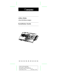
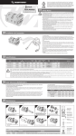
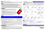
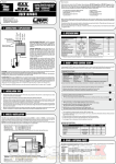
User Manual of XERUN V10 Motor
HW-SM599DUL-20130622
Thanks for purchasing Hobbywing Xerun V10 Sensored Competition Motor. High power motor can be very dangerous, so please read through
this manual carefully. Given that we have no control over the correct use, installation, application, or maintenance of our products, no liability
shall be assumed nor accepted for any damages, losses or costs resulting from the use of the product. Any claims arising from the operating,
failure or malfunctioning etc. will be denied. We assume no liability for personal injury and/or consequential damages resulting from our product
or our workmanship. As far as is legally permitted, the obligation to compensation is limited to the invoice amount of the affected product.
FEATURES
►
►
►
►
►
►
►
►
►
Designed to withstand extreme levels of use at its highest peak performance.
Complete new CNC cut motor case with extra front spoke ventilation slots.
Works as a sensored unit and also sensorless without the sensor cable attached.
Multiple steps of mechanical timing adjustable from 15 degree to 45 degree.
Minimal maintenance is required with precise machining technology which ensures a minimum tolerance end
play of the rotor shaft. Eliminating the copper shims used in most of today’s motors.
200℃ high temperature tolerance and high purity copper windings maximize conductivity and reliability.
200℃ high temperature tolerance sintered NdFeb (Neodymium, 35EH-LT) magnets.
Extreme low resistance multi-layered outlet PCB and high RPM NSK bearings.
Compliant with ROAR, IFMAR, BRCA and JMRCA rules, certificated by RoHS, CE, FCC etc.
TIMING ADJUSTMENT
► To adjust the timing, simply loosen the 2 short screws on the back of the motor and rotate the Sensor
Module Cover, noting the white-color lines on the motor and the mark (pointer) on the cover. After the
adjustment, please lock the 2 short screws.
► You can alter the timing on the motor to change the power-band and characteristics of the motor for best
and the most efficient performance. Neutral timing is 30 degrees with 15 degrees tuning either side. The
motor has 15 degrees timing on minimum setting (fully clockwise) to maximum 40 degrees (fully
anti-clockwise).
► The motor comes set to 30 degrees timing. Increasing the timing will increase the RPM of the motor whilst at
the same time increasing temperatures and losing efficiency. Higher timing will require a softer gear ratio.
We recommend you start with this setting and adjust based on your needs from that position.
► When setting your motor timing it is important to make sure your ESC is also set correctly. Please follow
your ESC instructions on how to do this. To check the motor temperatures during testing, simply drive for 3
laps of the track, stop and use an infrared temperature measuring instrument to make sure the motor is not
too hot. If the motor is too hot then allow the motor to cool before trying it again.
SPECIFICATIONS
KV
CAUTIONS
M odel
► Avoid incorrect connections between the electronic speed controller (ESC) and the motor.
(Picture 1)
► All wires and connections should be well insulated. Short-circuits can possibly damage the products.
► Never allow this product or other electronic components to come in contact with water, oil, fuel or other electro-conductive liquids. If this happens, stop
the use of your product immediately and let it dry carefully.
► Avoid overloading the motor due to wrong or too aggressive gear ratios. Different ESCs have different internal timings, follow the ESC instructions.
► Never apply full throttle if the pinion is not installed. Due to the extremely high RPMs without load, the motor can get damaged.
► Always wire up all the parts of the equipment carefully. If any of the connections come loose as a result of vibration, your model RC may lose control.
► Avoid soldering longer than 5 seconds at each soldering joint when replacing the power wires to prevent possible damage to the product due to
overheating of the components. Use a high power soldering station with at least 60W for soldering.
► Never allow the motor case to get over 100 degrees Celsius (212 degrees Fareheit) because the magnets maybe demagnetized by high temperature.
INSTALLATION AND CONNECTIONS
► Install the motor in its mount using M3 screws no longer than 8mm.
► There are 3 power wires coming from the ESC must be soldered to the motor. They are usually color coded as Blue for Wire A, Yellow for Wire B and
Orange for Wire C. When connecting the power wires between the ESC and motor, please make sure that you match ESC Wire A to Motor Phase A,
ESC Wire B to Motor Phase B and ESC wire C to Motor Phase C (This is VERY important).
► When using sensored ESC, make sure the sensor cable is clean and reliable. Connect the sensor cable to both ESC and motor in the correct direction.
► Double check you have all the connections correct before turning on the ESC (See picture 4).
(Picture 6)
R es i s -
W i thout
PN
tanc e
Load
( Ω)
( R PM /V)
C ur r ent
Peak
C ur r ent
D i a.
D i a. of
W i thout
Output
@Peak
&
Ex ter nal
Stoc k
W ei ght
Load
Pow er
Output
Length
Shaft
R otor
( g)
( A)
(W)
Pow er ( A)
( mm)
( mm)
3.5T
30401020032
9700KV
0.0026
9.2
600
120
V10-Rotor
173
4.5T
30401020033
7650KV
0.0040
6.9
490
108
-Φ5-12.5F
169
5.5T
30401020034
6450KV
0.0061
5.8
430
100
6.5T
30401020035
5340KV
0.0080
4.1
390
94
8.5T
30401020036
4165KV
0.0138
3.2
340
80
10.5T
30401020037
3450KV
0.0208
1.9
250
63
13.5T
30401020038
2760KV
0.0330
1.6
190
49
V10-Rotor
178
17.5T
30401020039
2210KV
0.0620
1.1
130
34
-Φ7-12.5
172
21.5T
30401020040
1760KV
0.0890
0.9
100
28
Ø=36
L=52.5
V10-Rotor
Ø=3.175
-Φ5-12.5
L=14.6
Appl i c ati on
1/10, 1/12 on-road Modified
172
1/10 on-road Modified;1/10 4WD off-road Modified
170
1/10 4WD off-road Modified
168
1/10 Drift; 1/10 2WD off-road Modified
174
1/10 Drift; 1/10 on-road Stock
174
1/10 on-road Stock
1/10 on-road Stock;1/10 rock crawler
► The “Peak Output Power” is measured with 7.4V input voltage and ESC at ZERO timing. This parameter is neither the “maximum input power” nor the
“rating power”, it is calculated by “RPM x Torque / 9550”. Because each factory runs a different testing platform, the above data may vary if the motor is
tested in different factories running different testing platforms.
► The “Current at Peak Output Power” is a guide used for selecting the suitable power system (ESC, Motor, Gear ratio, etc.) If the actual input current of
the power system is bigger than the peak parameter stated in the above table, this means that the power system settings/configuration is over its peak
(Or in other words, “overloaded”)
► The “KV” is measured without any load on the motor and ESC at ZERO timing. Please don’t run the motor without load for long periods of time (1 minute),
otherwise the motor may overheat.
GEARING
Below is a very rough idea of starting gear ratios for the motors. Please be aware that these are guide ratios for ESC with ZERO timing. Please always
check with other drivers using the same ESC/Motor combination at your track for a good starting point. If you have no idea about what gear ratio is most
suitable for your car, please begin with “softer” gearing and then adjust as needed.
(Picture 2)
(Picture 3)
C l as s
Batter y
3.5T
4.5T
5.5T
6.5T
8.5T
10.5T
13.5T
17.5T
21.5T
1/10 on- r oad ( Smal l tr ac k )
7.4V LiPo
11.0:1
9.5:1
8.5:1
8.0:1
7.3:1
6.8:1
6.3:1
4.3:1
3.8:1
1/10 on- r oad ( Bi g tr ac k )
7.4V LiPo
10.5:1
8.5:1
7.5:1
7.0:1
6.3:1
6.5:1
6.0:1
4.0:1
3.5:1
1/12 on- r oad
3.7V LiPo
25mm
29mm
32m
35m
38mm
42mm
51mm
66mm
66mm
2W D off- r oad
7.4V LiPo
11.1:1
10.3:1
8.5:1
8.0:1
7.0:1
6.0:1
5.5:1
4W D off- r oad
7.4V LiPo
12.0:1
10.8:1
8.9:1
8.0:1
7.0:1
6.0:1
5.5:1
T r uggy
7.4V LiPo
13.5:1
12.6:1
10.4:1
9.0:1
8.0:1
7.0:1
6.5:1
Not Available
PARTS LIST
The XERUN V10 Motor has the parts as below (Please also check picture 5 for reference).
1) Ball bearing x 1 (13.175x9.525x3.967mm)
6) Long screws x 3 (M2.50x45mm)
2) Rotor x 1
7) Cover of sensor module x 1
3)Front casing x 1
4) Sensor module x 1
5) Bottom casing x 1
8)Short screws 2 (M2.50x6.0mm) 9) Sensor wires x 2 (80mm, 200mm)
OPTIONS
Spar e Par t
PN
D es c r i pti on
Ball bearing
30830000001
30850000035
30850000036
30850000037
30850000038
30850000039
30850000040
30850000041
30850000042
30850000043
540 MOTOR BEARING-3.175
XERUN-V10-Rotor-Φ5-12.5F
XERUN-V10-Rotor-Φ5-12.5
XERUN-V10-Rotor-Φ7-12.5
XERUN-V10-Rotor-Φ5-13.0F
XERUN-V10-Rotor-Φ5-13.5F
XERUN-V10-Rotor-Φ5-13.0
XERUN-V10-Rotor-Φ5-13.5
XERUN-V10-Rotor-Φ7-13.0
Hall sensor module for V10 motor
(Picture 4)
Rotor
ASSEMBLY AND DISASSEMBLY
The XERUN V10 Motor is very strong in construction but also easy to
disassemble for maintenance. We recommend periodical checking of
the bearings and to clean the motor of dirt.
Please follow the steps in Picture 5 to assemble the motor.
When disassembling the motor, the sequences are reversed.
Sensor Module
Spec i fi c ati on
Thick magnets,
Thick magnets,
Thin magnets,
Thick magnets,
Thick magnets,
Thick magnets,
Thick magnets,
Thin magnets,
R2ZZ Ball Bearing, 3.175x9.525x3.967mm
with cooling fan, magnet hole Φ5, magnet length 12.5mm
w/o cooling fan, magnet hole Φ5, magnet length 12.5mm
w/o cooling fan, magnet hole Φ7, magnet length 12.5mm
with cooling fan, magnet hole Φ5, magnet length 13.0mm
with cooling fan, magnet hole Φ5, magnet length 13.5mm
w/o cooling fan, magnet hole Φ5, magnet length 13.0mm
w/o cooling fan, magnet hole Φ5, magnet length 13.5mm
w/o cooling fan, magnet hole Φ7, magnet length 13.0mm
* Please browse Hobbywing web for high-resolution picture 5.
www.hobbywing.com/product_show.asp?id=295
(Picture 5)
HOBBYWING TECHNOLOGY CO. LTD.
www.hobbywing.com