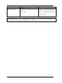
1
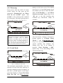
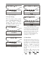
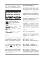
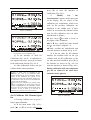
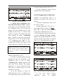
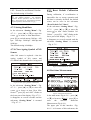
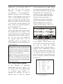
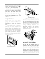
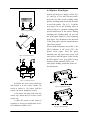
Please read this manual carefully before operation. O2 sensor contains corrosive. NO sensor contains acid. Avoid contact with skin, eyes and clothes. In case of contact, flush with water for at least 15 minutes. In case of urgency, please go to hospital for assistance immediately. Before the instrument is switched on, do not touch the internal running ventilation fan to avoid being clamped. Always protect the power supply by properly grounding the instrument. A high-quality power filter/surge protector is recommended. Do not power off the instrument when the pumped is still on. Power off the instrument during maintenance. Check the water filter frequently. Clean the filter bowl when it becomes full of water or debris. Failure to clean or replace filters results (see 6.2.2) in water damage to sensitive analyzer components. Water damage to the instrument voids your warranty. Before the work is ended every day, switch on the pump for a few minutes(see 4.8)to flow out the residual gases,then switch off the pump and return to the main menu, finally switch off the instrument. I Table of Contents 1 INTRODUCTION ............................................................................ 1 2 TECHNICAL SPECIFICATION.................................................... 1 3 DESCRIPTION OF THE UNIT ...................................................... 2 3.1 COMPOSTION .............................................................................................................. 2 3.2 FRONT PANEL ............................................................................................................. 2 3.3 REAR PANEL ............................................................................................................... 2 4 OPERATION....................................................................................... 3 4.1 PREPARATION ............................................................................................................. 3 4.2 MAIN MENU ................................................................................................................ 5 4.3 ZERO .......................................................................................................................... 6 4.4 CALIBRATION WITH GAS .............................................................................................. 6 4.5OIL TEMPERATURE CALIBRATION .................................................................................. 9 4.6 LEAK CHECK ............................................................................................................. 11 4.7 SETTING .................................................................................................................... 11 4.8 REAL-TIME MEASUREMENT ........................................................................................ 12 5 SERIAL COMMUNICATION AND PROTOCOL ........................ 14 5.1 CONNECTION AND SERIAL COMMUNICATION PARAMETERS.......................................... 14 5.2 DATA FORMAT AND COMMANDS OF PROTOCOL ........................................................... 14 6 MAINTENANCE ........................................................................... 16 6.1 OPEN THE ENCLOSURE ............................................................................................... 16 6.2 REPLACE FILTER ELEMENTS ....................................................................................... 16 6.3 REPLACE O2 AND NO SENSORS ................................................................................... 17 6.4 REPLACE PRINT PAPER(IF PRINTER IS EQUIPPED) .................................................... 18 7 TROUBLESHOOTING ................................................................. 19 II 1 Introduction 2 Technical Specification BulletPro 502 Gas Analyzer is for measuring CO, HC and CO2 in automotive emissions by the principle of non-dividing infrared absorption, measuring NO and O2 by the principle of electrochemical cell, calculating excessive air coefficient based on the composition of CO, CO2, HC and O2 measured. This instrument is equipped with gas bench with self-owned intellectual property right, microprocessor is embedded. It is an intellectual instrument with liquid crystal display and Chinese or English interface. Inductive RPM (engine-speed) measuring pliers, oil temperature sensor and printer are optional for measuring RPM and oil temperature, and printing measurement results. Operation Condition Temperature Relative humidity Atmospheric pressure Power supply Voltage Frequency Measurement Range HC (Hexane Equivalent) CO CO2 O2 NO (Not for NHA-406) RPM Oil Temperature Resolution HC CO CO2 O2 NO (Not for NHA-406) RPM Oil Temperature Indication Error 0ppm to 2000ppm HC 2001ppm to 10000ppm CO CO2 O2 NO (Not for NHA-406) Others Warm-up Time Output Interface Outer Dimension This instrument complies with the requirements of International Measurement Rules OIML R99/1998 (E) made by the Organization of International Measurement Law (OIML) and the National Metrological Verification Regulations # JJG 688 for class-1 instruments. It is applicable for environmental departments, vehicle inspection stations, automotive manufacturing factories and garages. +5℃ to +40℃ 5% to 95%non-condensing 70 kPa to 106 kPa AC220V±15% 50Hz ±1Hz 0ppm to 10000ppm 0% to 10% 0% to 20% 0% to 25% 0ppm to 5000ppm 300rpm to 8000rpm 0℃ to +120℃ 1ppm 0.01% 0.01% 0.01% 1ppm 10rpm 1℃ Absolute Relative ±12 ppm ±0.06% ±0.5% ±0.1% ±25ppm ±5% ±10% ±5% ±5% ±5% ±4% 10 minutes RS-232C (L)450mm(W)260mm(H)180m m Net Weight 1 7kg 3 Description of the Unit LCD, execute the corresponding operation; ●2—“K” key : corresponding to the functional sub-menu at the lower part of LCD, execute the corresponding operation; ●3— “▲” key:move the cursor on LCD upward and select the required item; corresponding to the functional sub-menu at the lower part of LCD, execute the corresponding operation; ●4— “▼” key:move the cursor on LCD downward and select the required item; corresponding to the functional sub-menu at the lower part of LCD, execute the corresponding operation. 3.1 Composition As shown in Fig. 3-1,the instrument is composed of the instrument host, short tube, pre-filter, sampling pipe, sampling probe and embedded micro printer (optional). Fig. 3-1 Composition of the Unit ●1—Instrument host : control measurement and analyze emissions components; ●2—Embedded micro printer (optional); ●3—Sampling pipe (5m) : connect pre-filter and sample gas inlet; ●4—Pre-filter: pre-filter sample gases; ●5—Short tube:connect pre-filter and sampling probe; ●6—Sampling probe : sample vehicle emissions. 3.3 Rear Panel Fig. 3-3 shows the layout of the rear panel. Names and functions of all the parts on rear panel: Calibration Gas Inlet Zero Gas Filter 3.2 Front Panel Power Communication/Printing Fig. 3-2 shows the layout of the front panel. Names and functions of all the parts on front panel: Gas Outlet RS-232C 1 2 3 4 5 6 Fig. 3-3 Layout of Rear Panel ●1—Oil temperature signal socket: input signal of oil temperature sensor; ●2—Mains socket and switch: the socket is for 220V AC power input, and the switch is for power on / off, with built-in 1A fuse and filter for mains noise; ●3—RS-232C socket:for communication with external computer; ●4—“COM/Printing” Selector : switch Fig. 3-2 Layout of Front Panel ●5—Liquid crystal display: display menus and measurement data; ●1—“S” key:corresponding to the functional sub-menu at the lower part of 2 4 Operation between “Printing” and “COM”. ●5—Gas outlet:main outlet for sample gas after measurement; ●6—Condenser and sample gas inlet: connect outlet of pre-filter via short tube, to introduce sample gas. Condenser can lower sample gas temperature to prevent condensation in sampling system; ●7—RPM signal socket: input signal of RPM measuring pliers or RPM adaptor; ●8—Outlet of NO sensor; ●9—Sensor cap: for protection of NO sensor and O2 sensor; ●10—Outlet of O2 sensor; ●11—Zero gas filter:filter the dust in air; ●12—Calibration gas inlet: used as inlet of standard gas, with pressure of approx. 0.02 MPa; ●13—Water filter: separate oil, dust and water in sample gas, replace the internal big / small filter elements as required. 4.1 Preparation 4.1.1 Installation a) As shown in Fig. 3-1 , firstly connect one end of the short tube with the end of the sampling probe, and the other end of short tube with inlet of the pre-filter. Then, connect one end of the 5-meter sampling pipe with outlet of the pre-filter, and the other end of sampling pipe with the sampling gas inlet. Noted that pre-filter should be connected as per shown in Fig. 3-1, check all connections and make sure that they are firmly connected without any leakage. b) Make sure that clean filter elements are mounted in pre-filter and water filter respectively. c) Respectively connect power cable, oil temperature sensor and RPM measuring pliers to the mains socket, oil temperature signal socket and RPM signal socket. d) Insert the oil temperature sensor into the hole of engine oil dipstick, clamp the RPM measuring pliers on the high tension cable of spark plug of 1st cylinder (Fig. 4-1-1). high tension cable signal socket sparkplug 1 2 4-cylinder engine RPM pliers 3 distributor 4 Fig. 4-1-1 Installation of RPM Pliers 3 4.1.2 Warm-up appears at the lower part of the display (see Fig. 4-1-3). User shall operate as per the prompts, press [K] to start leak check. Then, “Leak Checking ......” and “Please Wait for xx seconds” appear (Fig. 4-1-4). “XX sec.” is the leak checking time remained (by count-down, totally 10 seconds). Insert power cable into 220V AC mains socket, power on and warm up the instrument. “Warming Up!” and “Please Wait for xxx seconds” appear. “xxx seconds” is the warm-up time remained by count-down. The total warm-up time is 600 seconds (10 min.). See Fig. 4-1-2. Fig. 4-1-2 Warm-up after Power-on Fig 4-1-4 Leak Checking Warm-up time of 600 seconds is only for the case when the instrument is operated at ambient temperature of approx. 20℃. If ambient temperature is much higher than 20℃, the warm-up time may be shorter. If ambient temperature is much lower than 20℃, the warm-up time will be longer. The warm-up will be automatically ended as long as the technical requirements are reached. After leak check, if leakage is detected, a prompt appears as “Leakage, Please Check......” and “KStart Leak Check Again” (Fig.4-1-5). User shall check the sampling system carefully and eliminate any leakage (Fig. 6.4). If no leakage is detected, “Leak Checking ......OK!” appears (Fig. 4-1-6), and zeroing will be started automatically. 4.1.3 Leak Check Fig. 4-1-3 Waiting for Leak Check The instrument automatically enters the interface of Leak Check after warm-up, to check the sampling system for leakage. At this time, a prompt appears on the upper part of the display as “Cover The Probe With Tip Cap” and “KStart Leak Check” Fig 4-1-5 Leak Check Fails 4 Fig 4-1-6 Leak Check OK Fig 4-1-9 O2 Sensor is Aging 4.1.4 Auto Zeroing When auto zeroing is started, a prompt appears as “Zeroing...Please Wait!” (Fig. 4-1-7). When zeroing is completed, “Zeroing OK!” appears (Fig. 4-1-8). The prompts disappear and the main menu is displayed in several seconds. Fig 4-1-10 NO Sensor is Ageing If the life time of NO sensor or O2 sensor is exceeded, there are prompts to remind user to replace sensor in time after auto zeroing, see Fig. 4-1-9 and 4-1-10. After NO sensor is replaced, operate as per instruction for “New NO Sensor” and re-calibrate it(refer to 4.7.4). Fig 4-1-7 Zeroing 4.2 Main Menu The main menu is shown as in Fig. 4-2-1. The upper part is for name of the menu; the middle part is for displaying real-time data of HC, CO, CO2, O2, NO(Not for NHA-406), n (RPM), (excessive air coefficient) or A/F, T (oil temperature) and PEF value, the lower part is for prompts. Press [▲] or [▼] to move the menu forward or backward. There are six sub-menus: “SZERO”、“KMEAS”、“SLEAK”、 “KT CAL” 、“SSET” and “KGAS CAL”. Press Fig 4-1-8 Zeroing OK 5 4.4 Calibration with Gas [S] or [K] beside the sub-menu name to enter the corresponding sub-menu. Otherwise, return to the main menu from any sub-menu. The instrument may drift and the sensors may become ageing during service. Therefore, it is necessary to calibrate span after a period of service (generally 3-6 months). The O2 sensor and NO sensor shall be replaced after service of approx. 1 year due to ageing (see 6.3). After NO is replaced, operate as per instruction for “New NO Sensor” (see 4.7.4) and re-calibrate the channel before being used. (Note:NO is not for NHA-406) During calibration, if the deviation of data is very serious due to wrong operation and re-calibration is impossible, use option “Reset Default Cal. Values” (see 4.7.5) to reset the default values. (Note:calibration values for HC, CO, CO2 channels can be reset, but not for O2 channel and NO channel). Fig 4-2-1 Main Menu ●ZERO—manual zeroing (see 4.3); ●MEAS—enter sub-menu “Real-Time Measurement” (see 4.8); ●LEAK—manual leak check (see 4.6); ●T CAL—enter sub-menu “Oil Temperature Calibration” (4.5); ●SET—enter sub-menu “Setting Menu”(see 4.7); ●GAS CAL—enter sub-menu "Calibration With Gas” (see4.4). 4.4.1 Select Standard Gas One-component and three-component standard gases are required for span calibration, the components are as follows, a) Three-component standard gas ●CO:approx. 3.5 % vol; ●C3H( :approx. 2000 ppm(0.2 8 Propane) %)vol; ●CO2:approx. 14 % vol; ●N2(Nitrogen):residual value b) One-component standard gas( not for NHA-406) ●NO:approx. 1000 ppm(0.1 %)vol; ●N2(Nitrogen):residual value During calibration, the actual calibration values shall be subjected to the values on the tag on the standard gas cylinder, 4.3 Zero The instrument is with the function of auto zeroing. Zero is calibrated automatically and periodically (every half an hour). Usually zeroing is not required, it is performed only when user believes it necessary. In the main menu (see Fig. 4-2-1), press [▲] or [▼] and locate at sub-menu “SZERO”, press [S] to start zeroing. A prompt “Zeroing...Please Wait!” appears on the upper part of the display. If zeroing is completed,“Zeroing OK!” is displayed. After several seconds, the prompts disappear and the main menu is returned (Fig. 4-2-1). 6 without exceeding 15% of the above values. three-component gas cylinder used for this calibration, or the set values are modified, press [K] in the interface as shown in Fig. 4-4-1 to enter the interface as shown in Fig. 4-4-2. During calibration with three-component gas, the set value for NO channel can be ignored. NO calibration gas is excluded in accessories due to cylinder and validity problem. Please contact us for need of NO calibration gas. 4.4.2 Span Calibration for HC、 CO and CO2 Channels Calibration steps are as follows: a) Zeroing: calibrate zero as per 4.3 before calibration. b) In the main menu(Fig. 4-2-1), press [▲] or [▼] to locate at “KGAS CAL”, press [K] to enter the interface as shown in Fig. 4-4-1. Fig 4-4-2 Wait for Calibration e) In the upper part of interface of Wait for Calibration (Fig. 4-4-2), “Please Flow Calibration Gas, Press [K] When Data Is Stable.” is displayed. Follow the prompt, flow three-component gas via calibration gas inlet. Press [K] after readings are stable. “Calibrating HC/CO/CO2...” appears at the lower part of the display (Fig. 4-4-3),“Calibrating HC/CO/CO2 ... OK!” will be displayed in several seconds (Fig. 4-4-4),span of HC、CO and CO2 channels have been calibrated. The prompts disappear in several seconds and the main menu is returned(Fig. 4-2-1). f) If [K] is pressed without flowing standard gas to the instrument or the calibration values are out of range, “Calibrating HC/CO/CO2 ... Fails!” will be displayed at the lower part of the LCD. The prompt disappears in several seconds and the main menu is returned (Fig. 4-2-1), the calibration is invalid. Fig 4-4-1 Modify Concentration of Calibration Gas c) “Modify Cal. Gas Concentration” is displayed on the upper part of the LCD; set values of calibration gas components, which were used during the previous calibration, are displayed in the middle part. If these values do not match the nominal values used for this calibration, user can make modification as follows, ●S key—move to make it locate at any figure of the 4 channels; ●▲ or ▼ key—modify the value located by ,the value is ranged 0~9; ●K key—confirm the modification and enter the interface as shown in Fig. 4-4-2. d) If the set values for HC、CO and CO2 match the nominal values on the 7 press [K] to enter the interface of Calibration (Fig. 4-4-1). c) “Modify Cal. Gas Concentration” appears at the upper part of the display; the set values of the calibration gas components, which were used for the previous calibration, are displayed in the middle part. If these values do not match the nominal values used for this calibration, user can make modification as follows, ●S key—move to make it locate at any figure of the 4 channels; ●▲ or ▼ key—modify the value located by ,the value is ranged 0~9; ●K key—confirm the modification and enter the interface as shown in Fig. 4-4-2. d) If the set value for NO channel matches the nominal value on the gas cylinder used for this calibration, or the set value has been modified, press [K] in the interface as shown in Fig. 4-4-1 to enter the interface as shown in Fig. 4-4-2. During calibration with one-component gas, the set values for the other three channels can be ignored. Fig 4-4-3 Calibrating Fig 4-4-4 HC CO CO2 Calibration OK g) In the interface of Wait for Calibration (Fig. 4-4-2),if calibration is not required any more, press [S] to return to the main menu directly (Fig. 4-2-1). h) After calibration, remove the gas cylinder before other operations. Note: A check valve is assembled at the calibration gas inlet on the instrument. When flowing calibration gas into the instrument, aim the nozzle of the calibration gas cylinder at the calibration gas inlet on the instrument, slightly force it downward to open the valve, and the calibration gas will enter the instrument. When using any calibration gas cylinder other than the one supplied by us, if the nozzle of the gas cylinder is inapplicable for this instrument, and the check valve can not be opened, use the adapter in the accessories. To use it, fasten it on the inlet of calibration gas, the check valve will be opened. 4.4.3 Calibrate NO Channel(not for Fig 4-4-5 Calibrating a) Zeroing: calibrate zero as per 4.3 before span calibration. b) In the main menu (Fig. 4-2-1), press [▲] or [▼] to locate at KGAS CAL, 8 to the main menu directly (Fig. 4-2-1). h) After calibration, remove the gas cylinder before other operations. 4.5 Oil Temperature Calibration Calibrate oil temperature when it is deemed as necessary. The steps are as follows, a) Insert oil temperature sensor, wait for 5 min. or above. b) In the main menu(Fig. 4-2-1), press [▲] or [▼] to locate at “KT CAL”, press [K] to enter the interface of Oil Temperature Calibration (Fig. 4-5-1). c) If oil temperature sensor is not inserted, a prompt “Install Oil Temp. Probe!” appears. The prompt disappears in a few seconds and the main menu is returned (Fig. 4-2-1). This calibration is invalid. Fig 4-4-6 NO Calibration OK e) “Please Flow Calibration Gas, Press [K] When Data Is Stable.” appears at the upper part of the interface of Wait For Calibration (Fig. 4-4-2). Follow the prompt, flow NO calibration gas via the sample gas inlet (Fig. 3-3, item 6) with pressure of approx. 0.02 Mpa. Press [K] after readings are stable. “Calibrating NO...” appears at the lower part of the display (Fig. 4-4-5). The prompt changes to be “Calibrating NO... OK!” in a few seconds (Fig. 4-4-6). The span of NO channel has been calibrated. The prompt Flow NO standard gas via the sample gas inlet on the instrument, the flow should be within 5~ 6L/min. Do not calibrate it without flowing NO standard gas disappears in a few seconds and the main menu is returned (Fig. 4-2-1). f) If [K] is pressed without flowing standard gas into the instrument or the calibration value is out of range, “Calibrating NO ... Fails!” appears at the lower part of the display. The prompt disappears in several seconds and the main menu is returned (Fig. 4-2-1), the calibration is invalid. g) In the interface of Wait for Calibration (Fig. 4-4-2),if calibration is not required any more, press [S] to return Fig 4-5-1 Setting Calibration Values at Ambient Temperature Fig 4-5-2 Wait for Calibration at Ambient Temperature d) Fig. 4-5-1 calibration values 9 shows at settings ambient temperature,press [▲] or [▼] to modify the current setting at ambient temperature (subject to the current reading of the temperature measuring device). After modification, press [K] for the next operation(Fig. 4-5-2). If oil temperature calibration is not required any more,press [S] to exit and return to the main menu (Fig. 4-2-1). and the main menu is entered (Fig. 4-2-1),this calibration is invalid. Fig 4-5-4 Calibration at Ambient Temperature Completed Fig 4-5-3 Calibrating at Ambient Temperature e) In the interface of Wait For Calibration At Ambient Temperature (Fig. 4-5-2), follow the prompt,place the oil temperature sensor in ambient air, press [K] when the reading is stable, and start calibration at ambient temperature (Fig. 4-5-3). If such calibration is not required, press [S] to skip it and enter the interface of Setting Calibration Values at High Temperature Point (Fig. 4-5-5). f) After calibration at ambient temperature is completed, “Calibrating...OK!” appears at the lower part of the displayed (Fig. 4-5-4). In several seconds, the interface of Setting Calibration Values at High Temperature Point is entered (Fig. 4-5-5). If oil temperature sensor is not inserted or the set values are out of range, “Cal. Value Out of Range, Calibration Fails!” appears at the lower part of the display. The prompt disappears in a few seconds Fig 4-5-5 Setting Calibration Values at High Temperature Point g) Fig. 4-5-5 shows the calibration values at high temperature point,press [▲] or [▼] to modify the set values at high-temperature environment (100℃ boiled water or other high-temperature device with known temperature). After modification, press [K] for the next operation (Fig. 4-5-6). If high-temperature calibration is not required any more,press [S] to exit and return to the main menu (Fig. 4-2-1). Fig 4-5-6 Wait For Calibration at High Temperature Point 10 h) In the interface of Wait For Calibration At High-Temperature Point (Fig. 4-5-6), follow the prompt,place the oil temperature sensor in 100ºC boiled water or other high-temperature device with stable temperature, press [K] when the reading is stable, start calibration at high-temperature point. If such calibration is not required, press [S] to exit and enter the main menu (Fig. 4-2-1). i) After calibration at high-temperature point is completed, “Calibrating...OK!” appears at the lower part of the display and the main menu is returned (Fig. 4-2-1). If oil temperature sensor is not inserted or the set values are out of range, “Cal. Value Out of Range, Calibration Fails!” appears at the lower part of the display. The prompt disappears in a few seconds and the main menu is entered (Fig. 4-2-1), this calibration is invalid. main menu is returned in several seconds (Fig. 4-2-1). c) If leakage is detected, user should check the whole sampling system carefully and eliminate leakage (see 6.4), otherwise “Leakage, Please Check......”will be always displayed. 4.7 Setting This sub-menu is for setting fuel type and communication baud. In the main menu (Fig. 4-2-1),press [▲] or [▼] to locate at “SSET”,press [S] to enter the interface of “Setting Menu” (Fig. 4-7-1). 4.7.1Leak Check at Power-On In the sub-menu “Setting Menu”(Fig. 4-7-1),press [▲] or [▼] to move the cursor to item Power-ON Leak Check,press [K] to switch between YES and NO. YES is for automatic leak check at each power-on, NO is for no automatic leak check at each power-on. The default setting is YES. 4.6 Leak Check Automatic leak check is done after warm-up (which is related to the setting at 4.7.1). User may run leak check at any time as required, the steps are as follows, a) In the main menu (Fig. 4-2-1), press [▲] or [▼] to locate at “SLEAK”, press [S] to enter the interface of Leak Check. b) Follow the prompts at the upper part of the display, cover the probe with tip cap,press [K],leak check is done in 10 seconds. if leakage is detected,“Leakage, Please Check......” is displayed. If no leakage is detected , “Leak Checking ......OK!” is displayed. The Fig 4-7-1 Setting Menu 4.7.2 Setting Fuel Type In the sub-menu “Setting Menu”(Fig. 4-7-1),press [▲] or [▼] to move the cursor to locate at item Fuel Type, press [K] to switch among Gasoline、 11 4.7.5 Reset Default Calibration Value LPG、Natural Gas and Ethanol Gasoline. The default setting is Gasoline. During calibration, if re-calibration is impossible due to wrong operation and the data is seriously deviated, the default values can be reset in the sub-menu “Reset Default Cal. Values”. In the sub-menu “Setting Menu”(Fig. 4-7-1),press [▲] or [▼] to move the cursor to item “Reset Default Cal. Values”,press [K],“OK!” flashes at the lower part of the display(Fig. 4-7-3), it disappears at several seconds and the sub-menu “Setting Menu” is returned (Fig. 4-7-1). When fuel type is set as “Gasoline”、“Natural Gas” and “Ethanol Gasoline” , HC indication represents hexane equivalent, with the mark of “HC”;when “LPG” is set,HC indication represents propane equivalent, with the mark of “C3H8”. 4.7.3 Setting Baud Rate In the sub-menu “Setting Menu”(Fig. 4-7-1),press [▲] or [▼] to move the cursor to locate at item Baud Rate, press [K] to switch among 300 bps、600 bps、1200 bps、2400 bps、4800 bps and 9600 bps. The default setting is 9600bps. 4.7.4 Clear Ageing Symbol of NO Sensor After NO sensor is replaced,clear the ageing symbol of NO sensor and re-calibrate this channel before being used. Fig 4-7-3 Reset Default Cal. Values 4.8 Real-time Measurement Fig 4-7-2 Clear Ageing Symbol of NO Sensor In the sub-menu “Setting Menu”(Fig. 4-7-1),press [▲] or [▼] to move the cursor to locate at item “New NOx Sensor”,press [K] and “OK!” flashes at the lower part of the display(Fig. 4-7-2), it disappears at several seconds and the sub-menu “Setting Menu” is returned (Fig. 4-7-1). / Fig 4-8-1 Real-time Measurement In the main menu(Fig. 4-2-1),press [▲] or [▼] to locate at “KMEAS”,press [K] to enter the interface Real-time Measurement (Fig. 4-8-1). The upper part of this interface ( Fig. 4-8-1)is for name of this sub-menu; the 12 middle part is for real-time values of HC 、 CO 、 CO2 、 O2 、 NO ( Not for NHA-406)、n(RPM)、λ(Excessive air co-efficient)、T(oil temperature) and PEF; the lower part is for prompts. There is a flow indicator on the up left corner,3-5 grids indicates proper flow. 1 grid or no grid represents insufficient flow. When the air path is blocked, the symbol “F” on the left of the flow indicator will flash.(In this case, user shall eliminate it as per the method in 6.2) After “Real-time Measurement” is started,the pump will be started. Insert the sampling probe into tailpipe of the vehicle being tested for a depth of 400mm. The display shows the real-time values of HC、CO、CO2、O2、NO、λ and PEF. If the optional RPM pliers and oil temperature sensor are mounted, the real-time RPM (n) and oil temperature (T) will be displayed. correctly and quickly, press [▲] or [▼] in 1 2 this interface to switch between n or n , the real-time RPM values will be switch automatically as per the ignition way. 4.8.2 Lock data and Print Data During real-time measurement,if real-time value lock-out is necessary, press [S] in the interface of Real-Time Measurement(Fig. 4-8-1), enter the interface of Data Lockout(Fig. 4-8-2) Fig 4-8-2 Data Lockout In the interface “Data Lockout” (Fig. 4-8-2), all the real-time data can be locked for user to record the current measurement data. If optional printer is equipped, and “COM/Printing” Selector on the rear panel of the instrument (Fig. 3-3, item 4) is switched to “Printing”, user may lock the data in this interface (Fig. 4-8-2), press [K] to print the locked data, see Fig. 4-8-3. Engine speed is tested indirectly by using the engine ignition pulse. As there are many engine types and models, the construction and performance vary greatly, the RPM pliers equipped on this instrument is not effective to all the engines, the effectiveness is approx. 80%. If this is not effective to some engines, recommend to use other RPM devices. The interference to some engines is great. When RPM and oil temperature are measured, due to the interference, the instrument does not work properly because of the slow updating of the measurement data. In such case, try to take out the oil temperature sensor. If the problem still can not be solved, recommend other measuring methods. HC: CO: CO 2 : O2 : NO: n: T: λ: 4.8.1 Change Engine Ignition In the interface of Real-Time Measurement(Fig. 4-8-1),figure ”1” on the up right corner of the RPM symbol “n” represents single ignition; “2” represents two ignitions. In order to facilitate user to select the ignition 0122 00.52 12.05 00.05 0032 2540 093 1.010 Fig 4-8-3 Print Out 13 ppm % % % ppm rpm ℃ 5.1 Connection and Serial Communication Parameter In the interface of Data Lockout(Fig. 4-8-2),press [S] to return to the main menu directly(Fig. 4-2-1). 5.1.1 Connection For printing data, “COM/Printing” selector on the rear panel must be set to “Printing”. 4.8.3 Stop Measurement RS-232 connection is as show on Fig. 5-1. Real-time Before real-time measurement is stopped, take out the sampling probe from the vehicle tailpipe. Press [K] in the interface of Real-Time Measurement (Fig. 4-8-1), or press [S] in the interface of Data Lockout (Fig. 4-8-2), real-time measurement can be stopped, stop the pump and return to the main menu(Fig. 4-2-1). Fig 5-1 RS-232 Connection 5.1.2 RS-232C Serial Communication Parameter After measurement is completed and before power is switched off, it is recommended to set the instrument at the status of measurement, The pump will be on for approx. 10 minutes. And place the sampling probe into clean air, let clean air flow into the instrument to blow off the exhaust gas left in the piping. ●Baud Rate: 9600 Baud;(it is related to the setting in 4.7.3); ●Character Length:1 start bit,8 data bit, 1 stop bit; ●Parity: None 5 Serial Communication and Protocol 5.2 Data Format and Command of Protocol The RS-232 socket (Fig. 3-3, item 3) on the rear panel of the instrument is the serial communication port for connection with the external computer for transmitting measurement data or for other operations. In the interface of Main Menu (Fig. 4-2-1) or Real-time Measurement (Fig. 4-8-1), external computer can communicate data with the instrument. 5.2.1 Pump-on External computer sends : 01H (hexadecimal,same for the following commands) Instrument responds:ACK(06H) 5.2.2 Pump Off External computer sends:02H Instrument responds:ACK(06H) For data communication, “COM/Printing” selector on the rear panel must be switched to “COM”. 5.2.3 Access Real-Time Data External computer sends:03H Instrument responds:ACK(06H),HC, CO,CO2,O2,NO,n,T,λ,check sum 14 5.2.4 Check Instrument Status instrument responds BUSY(05H). External computer sends: 14H Instrument responds during warm-up and leak-check:48H Instrument responds during zeroing:5AH Instrument responds during stand-by (in the main menu):57H 5.2.12 Data Format a) ACK:06H,one byte. b) HC:HC data, integer with symbol (two bytes), high order first, unit as ppm. For example, the measurement result of HC is 1234 ppm, the HC data will be 04D2H. (If fuel type is set as gasoline, natural gas or ethanol gas, it is expressed with n-hexane equivalent; if fuel type is set as LPG, it is expressed with propane equivalent). c) CO:CO data, integer with symbol (two bytes), high order first, unit as 100 times of percent. For example, the measurement result of CO is 1.23%, the CO data will be 007BH. d) CO2 : CO2 data, integer with symbol (two bytes), high order first, unit as 100 times of percent. For example, the measurement result of CO2 is -0.25%, the CO2 data will be 0FFE7H. e) O2:O2 data, integer with symbol (two bytes), high order first, unit as 100 times of percent. For example, the measurement result of O2 is 0.25%, the O2 data will be 0019H. f) NO:NO data, integer with symbol (two bytes), high order first, unit as ppm. For example, the measurement result of NO is 15ppm, the NO data will be 000FH. g) n:RPM data, integer with symbol (two bytes), high order first, unit as r/min (Note: RPM is related to engine stroke). h) T:oil temperature data, integer with symbol (two bytes), high order first, unit as ℃. i) λ:excessive air coefficient data, integer with symbol (2bytes),high order The instrument doesn’t respond any command if it is not at warm-up, leak-check, zeroing or stand-by status. 5.2.5 Set Fuel as Gasoline External computer sends:06H Instrument responds:ACK(06H) 5.2.6 Set Fuel as LPG External computer sends:07H Instrument responds:ACK(06H) 5.2.7 Set Fuel as Natural Gas External computer sends:09H Instrument responds:ACK(06H) 5.2.8 Set Fuel as Ethanol-Blended Gasoline External computer sends:19H Instrument responds:ACK(06H) 5.2.9 Set Ignition as Single” External computer sends:0AH Instrument responds:ACK(06H) 5.2.10 Set Ignition as Two External computer sends:0BH Instrument responds:ACK(06H) 5.2.11 Others If the above commands are sent during zeroing, warm-up or leak-check, the 15 first, data is increased by 100 times. For example, the measurement result of λis 1.030,the λ data will be 0067H. j) Check sum: sum of all the foregoing data from a) to i), integer without symbol (two bytes, high order first, carry abandoned). Check Sum = 06H + HC + CO + CO2+ O2+NO(Not for NHA-406)+n + T+λ 6 Maintenance Fig 6-2 Pull Out Printer b) Remove the four fastening bolts between the casing and the base panel and the two fastening bolts on the rear panel and above the calibration gas inlet. Pull the two side panels outward and pull the casing backward, disconnect the grounding terminal in the enclosure, remove the casing and open the instrument enclosure. 6.1 Open Enclosure Switch off the power supply before opening the instrument enclosure for maintenance or repair with following steps: a) If optional printer is mounted, follow Fig. 6-1, remove the front cover from the printer with slight force, press the plastic sheets on the two sides of the printer (Fig. 6-2), pull out the whole printer from the instrument enclosure, disconnect the plug connected with the instrument (Fig. 6-3). Fig 6-3 Pull Out the Plug 6.2 Replace Filter Elements In case that the sampling system is clogged by dust, oily mud or any other dirt in emissions, the flow of the sampling system is seriously reduced, the flow indicator on the up left corner of the display will be less than two grids, and the symbol “F” below the flow indicator will flash. Under such circumstance, turn off Fig 6-1 Dismantle Front Cover 16 the power supply to the instrument, check and clean the sampling probe, sampling pipe and short tube, replace the filter elements of the pre-filter and water filter. After eliminating the clogging, the instrument will work normally. 6.2.1 Replace Pre-filter a) Uninstall the sampling pipe and the short tube from the failed pre-filter; Fig 6-4 Water Filter ● ● ● ● ● ● ● b) Take the new pre-filter from the instrument accessories, connect it with the sampling pipe and short tube as per the flow direction arrow marked on the shell, the short tube is connected with the small end of the pre-filter and sampling pipe is connected with the big end. (see Fig. 3-1) 1——Water Bowl 2——Nut 3——Small Filter Element 4——Clamping Ring 5——Big Filter Element 6——Bolt 7——Base 6.2.3 Replace Zero Gas Filter 6.2.2 Replace Element Water Filter The life time of the zero gas filter (Fig. 3-3, item 11) is as long as 2-3 years. During replacement, remove the failed zero gas filter from the bending pipe connected on the rear panel, install the new one as per the direction marked on the rear panel. As shown in Fig. 6-1, turn the water bowl of the water filter counterclockwise and take it out, loosen and take out the nut, remove the failed small filter element, clamping ring and failed big filter element in sequence, replace them with new ones. Install all the above parts in reverse sequence. Never scratch the surface by hard objects when assembling the new filter elements, otherwise the filtering will be affected. Fasten the nut and the water bowl to prevent any leakage. 6.3 Replace O2 and NO Sensors Due to ageing, O2 sensor and NO sensor need replacement after service for approx. one year, replacement steps follows, a) Counterclockwise turn the two screws below the sensor caps on the rear panel, see Fig. 6-5. b) Follow the directions in Fig. 6-6 to open and unload the sensors caps. c) Disconnect the sensor plugs and remove the failed sensor counterclockwise, as shown in Fig. 6-7. 17 6.4 Replace Print Paper Switch off the power supply, follow Fig. 6-1 and Fig. 6-2 to take out the printer, press the two sides of the winding shaft, pull the winding shaft downward and take it out of the printer(Fig. 6-5). Load the new paper roll on the winding shaft as shown in Fig. 6-6,push the winding shaft upward and load it in the printer. During installing the winding shaft, do not roll the print paper tightly to avoid clamping print paper. Pay attention to the direction of the print paper, only the smooth thermo side can be printed. Power on the instrument, press [SEL],the [SEL] indicator is off, press [LF],the printer feeds paper. Feed the paper manually into the paper entry, paper will enter slowly until the paper comes out the head for approx. 1cm,press [SEL] to stop feeding and the indicator [SEL] is on. After paper loading, install the printer in the instrument. Fig 6-5 Turn the Screws Fig 6-6 Unload the Sensor 1 1 2 2 Fig 6-7 Unload the Sensor d) Rotate the new sensor clockwise and install it in the sensor holder. Be noted to fasten it. O2 sensor and NO sensor can not be installed reversely. e) Re-insert the plug and close the sensor cap, fasten the two screws on the sensor cap. f) After O2 sensor or NO sensor is replaced, re-zero as per instructions in 4.3, NO calibration follows 4.4.3. Fig 6-5 Unload Paper Shaft Fig 6-6 Load Print Paper 18 7 Troubleshooting Problem Reason Solution Switch on the power supply, *The power cable is not connected well; *Connect the power cable properly; the instrument does not work, *The fuse is burnt. *Replace the fuse; no display on the LCD. *LCD is broken. *Contact us to repair LCD. HC residue is serious. After *Ambient air is polluted; *Place the sampling probe in clean air; zeroing and switching on the *The concentration of HC contained in the *Place the sampling probe in clean air, pump to draw in ambient air, exhaust gases is too high or the measurement follow instruction in 4.8 to enter Real-Time the HC reading is still high. time is too long, HC is deposited and attached Measurement status, then work for some in the sampling system. time(approx. 10 minutes),flow in clean air to blow off the residual HC in sampling system. If this does not work, remove the sampling probe and sampling pipe, blow them with compression air. *Replace pre-filter and water filter.(see 6.2) *Contact us to replace the internal piping. Leak check fails. *Leakage at the connection between the water *Check whether the gasket fails or is lost or bowl and the base. the connection is fastened, replace the *The sampling probe inlet is not blocked well. gasket or fasten it. *Leakage at the connection of sampling probe. *Block the sampling probe tightly. *Poor sealing at the two ends of the sampling *Re-connect and re-fasten connection of the pipe or short tube due to ageing. sampling probe. *The sampling pipe is broken or punctuated. *Cut the ageing part or replace it with a new *Leakage of the one-way valve. one. *Accumulator of the pump is broken. *Replace the sampling pipe. *replace the one-way valve. *Replace the accumulator. The measurement indications *The sampling probe is not inserted into the *Insert the sampling probe into the vehicle of HC、CO and CO2 channels vehicle tailpipe. tailpipe properly. are zero or very low. *The pump is broken. *Replace the accumulator or the pump. *The internal pipes are loosened. *Re-connect the pipes. *The bench is broken. *Contact us to repair the bench. During real-time measurement, *The sampling system is blocked by dust, oil *Replace pre-filter(se 6.2.1). symbol “F” on the left-up mud, etc. in the emissions, the flow is greatly *Replace water filter(see 6.2.2). corner flashes. reduced. The measurement indications *The O2 sensor is ageing or the service is of O2 channel is high or beyond one year. *Replace O2 sensor(see 6.3). incorrect. The indication of NO channel *Wrong NO calibration. *Reset calibration value (see 4.7.5),re-calibrate NO channel(see 4.4.3). varies greatly or the indication is incorrect. initial *Connection of NO sensor is bad. *Re-connect the NO sensor and re-calibrate this channel. *The NO sensor is ageing or the service is 19 *Replace NO sensor(see 6.3). beyond one year. Printer does not work. *Printer and the instrument are not connected *Check the connection cable between the correctly. printer and the instrument, re-connect and *No print paper. fasten it. Press [SEL] on the printer,the green indicator is on. *Replace print paper(see 6.4). If problems still can not be solved even though the above solutions are tried or other failures are found, please contact the local sales agent or visit http://www.interequip.com.au for more details. 20