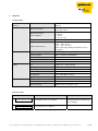
1
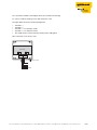
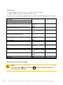
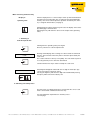
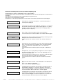
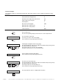
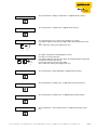
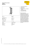
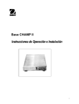
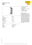
PROFIBUS-PA USER MANUAL DIGITAL FIELDBUS DISPLAY FD-48-T317/EX F1089/01 2 /0407 Hans Turck GmbH & Co.KG • Witzlebenstraße 7 • 45472 Mülheim/Ruhr • Germany • Tel. 0208 4952-0 • Fax 0208 4952-264 • www.turck.com Contents 1 Notes for explosion-proof equipment ............................................................................................................................... 4 2 FD-48-T317/Ex Digital Display ............................................................................................................................................ 5 Brief description............................................................................................................................................................. 5 Overview of features ...................................................................................................................................................... 5 3 Mounting and connection.................................................................................................................................................... 6 Mounting........................................................................................................................................................................ 6 Connection .................................................................................................................................................................... 6 Commissioning .............................................................................................................................................................. 8 Restoring the factory set parameters (RESET) .............................................................................................................. 8 4 Operation .............................................................................................................................................................................. 9 LCD front view ............................................................................................................................................................... 9 Status informationen...................................................................................................................................................... 9 Keypad........................................................................................................................................................................... 9 LED display.................................................................................................................................................................. 10 Menu structure, parameter entry ................................................................................................................................. 11 Parameters in the Entry menu ..................................................................................................................................... 12 Parameter example...................................................................................................................................................... 14 5 Appendix ............................................................................................................................................................................. 17 Technical data ............................................................................................................................................................. 17 Error messages............................................................................................................................................................ 17 Dimension drawing FD-48-T317/Ex............................................................................................................................. 18 Definition of the used symbols WARNING This sign is placed next to a warning indicating a potential hazard. This can relate to personal injury as well as to system (hardware and software) and equipment damage. The user should interpret this symbol as follows: exercise extreme caution. NOTE This sign is located next to general notes providing important information on individual or stepwise work procedures. The relevant instructions can facilitate work and possibly help to avoid additional work resulting from faulty procedures. Hans Turck GmbH & Co.KG • Witzlebenstraße 7 • 45472 Mülheim/Ruhr • Germany • Tel. 0208 4952-0 • Fax 0208 4952-264 • www.turck.com 3/0407 1 Notes for explosion-proof equipment Scope and regulations The notes and warnings stated in these operating instructions must be observed in order to ensure safe and proper operation. This equipment must only be used for its intended use. It complies with EN 60079 regulations, in particular EN 60079-14 “Electrical Equipment for Explosion Hazardous Areas” and EN 50281-1-2 “Electrical Apparatus for Use in the Presence of Combustible Dust”. It is suitable for use in hazardous locations that are endangered by gases and vapours which are assigned to the explosion group stated on the type label. The erection and operation of explosion-proof controllers and systems must be carried out according to the relevant national regulations and directives. General notes Correct and safe operation of this equipment relies on appropriate transport and storage, correct installation as well as careful operation and maintenance. Any work on the equipment must only be carried out by trained and qualified personnel. The electrical characteristic values stated on the type label and the EC type examination certificate TÜV 07 ATEX 553588, and any special requirements related to this must be observed. If the installation is outdoors, it is recommended that the explosion-proof device is protected against direct influence of the weather, e.g. by means of a protective cover. The maximum permissible ambient temperature is stated in the technical data in the Appendix. Intrinsically safe circuits The installation instructions stated in the EC type examination certificates of the intrinsically safe electrical equipment must be observed. The safety-related electrical values stated on the type label must not be exceeded in the intrinsically safe circuit. When intrinsically safe circuits are interconnected, the occurrence of a voltage and/or current addition must be tested. The intrinsic safety of the interconnected circuits must be ensured (EN 60079-14, section 12) The certification of intrinsic safety is not required if the display device is connected to a FISCO-compliant fieldbus. WARNING Working on live electrical installations and equipment is expressly forbidden in hazardous locations. This does not apply to work on intrinsically safe circuits. In special cases, work can also be carried on non-intrinsically safe circuits, in which case it must be ensured that an explosive atmosphere is not present during the work. Isolation must only be tested with permissible explosion-proof measuring devices. Earthing and short-circuiting must only be carried out if there is no explosion hazard at the point of earthing and short-circuiting • Danger of static charging. Only clean with damp cloth! • Do not open in an explosive dust-loaded atmosphere! 4/0407 Hans Turck GmbH & Co.KG • Witzlebenstraße 7 • 45472 Mülheim/Ruhr • Germany • Tel. 0208 4952-0 • Fax 0208 4952-264 • www.turck.com 2 FD-48-T317/Ex Digital Display Brief description The FD-48-T317/Ex digital display device is used for displaying process information of fieldbus nodes connected to the PROFIBUS-PA network. The display device operates as a “listener”, i.e. it does not appear on the bus as a node with its own address and also does not increase the traffic on the bus. The display device listens to the data (only publisher/subscriber data traffic) published by a field device. The process value of the actuator or sensor is displayed as a five-digit number, and the process value status can be scanned via status key. As well as the display for measured values, the device also features a 41 segment bargraph for trend monitoring that can be scaled separately from the displayed value. The device is also provided with a rugged powder-coated die-cast aluminium housing. The FD-48-T317/Ex digital display device can be used in Zone 1 and 2 (hazardous area exposed to gas) as well as in Zone 21 and 22 (area exposed to dust hazards). Overview of features FD-48-T317/Ex Ex i display device in the fieldbus network Uses the auxiliary supply from the fieldbus – use in an Ex environment is simple since no power supply cables are required Provided with an easy to install bus node connection. Explosion protection for gas and dust-laden environments: II 2(1) G, EEx ia IIC T6 and T5 II 2 D, IP65 T 70°C Display: Five-digit 7-segment display (display range from -9999 to (+)99999) LCD display with 30 mm digit height Fast response bargraph for trend monitoring (41 segments, image generated several times per second) Ergonomics: Microprocessor technology for extensive paramaterisation options Status control key All parameters retained after power failure Parameters can be modified during operation Exchangeable unit of measure symbols Housing: Rugged die-cast aluminium housing Dimensions (H x W x D) 140 x 140 x 72 mm Hans Turck GmbH & Co.KG • Witzlebenstraße 7 • 45472 Mülheim/Ruhr • Germany • Tel. 0208 4952-0 • Fax 0208 4952-264 • www.turck.com 5/0407 3 Mounting and connection Mounting Choose a solid surface for fastening the display device. The device has an integrated paper strip for writing the unit of measure symbols. • To write the required unit of measure symbols on the paper strip, unscrew the four screws of the housing cover and remove the cover. • The unit of measure symbol slot is located under the display panel. Inserting the unit of measure symbols: • Insert the prepared paper strip with the symbols facing the front into the unit of measure symbol slot on the inside of the housing cover. • Screw on the cover to the housing bottom. Connection WARNING The device should only be connected to the PROFIBUS-PA network. The maximum values for terminal voltage and short-circuit current specified in the EC type examination certificate TÜV 07 ATEX 553588 must be observed. The device must be earthed if there is a risk of static charge. There must be a low-resistance connection between shield of the connection cable and the screw connection. When used in hazardous locations the housing must be connected to the equipotential bonding via the external earthing connection (EN 60079-14, para. 12.2.2.3). Any multiple earthing must only be implemented using a capacitive connection (EN 60079-14, para. 12.2.2.3c). 6/0407 Hans Turck GmbH & Co.KG • Witzlebenstraße 7 • 45472 Mülheim/Ruhr • Germany • Tel. 0208 4952-0 • Fax 0208 4952-264 • www.turck.com The connection terminals of the display device are located in the housing. To connect, undo the housing screws and remove the cover. The figure below shows the terminal arrangement: • • • • • Terminal 1: – Terminal 2: + Terminal 3: – For other bus nodes Terminal 4: + For other bus nodes The shield must be connected to the housing of the cable gland After connection screw on the cover. Terminals 1 2 3 4 Ground bolt + + Shield Hans Turck GmbH & Co.KG • Witzlebenstraße 7 • 45472 Mülheim/Ruhr • Germany • Tel. 0208 4952-0 • Fax 0208 4952-264 • www.turck.com 7/0407 Commissioning 1. A display segment test is carried out for one second after the device is connected. 2. The version number of the device is displayed for another second. The device is factory set with the following parameters when commissioned for the first time after initial connection: Description Number of displayed channels Automatic channel switching Fieldbus address(es) Index (Offset) of the first byte of the value to be displayed from the received user data Dispaly of input i.e. output data Interchange of the most significant and the least significant bytes of the floating point values Set decimal place Display bargraph Min value for bargraph Max value for the bargraph Status bargraph Measured value scaling factor Measured value scaling offset Menu code word Menu end Display Parameter Chan Auto Addr.1 Addr.2 Addr.3 OFFS1 OFFS2 OFFS3 OUT.I1 OUT.I2 OUT.I3 SFL1 SFL2 SFL3 dP.PO1 dP.PO2 dP.PO3 bAr bar.L1 bar.L2 bar.L3 bar.H1 bar.H2 bar.H3 STATU SFAC1 SFAC2 SFAC3 SOFS1 SOFS2 SOFS3 CodE END 1 No 0 1 In (input data) No 1 Yes 0 100 Yes 1,000 0,0 0001 / Restoring the factory set parameters (RESET) NOTE and the Right key Pressing the Enter key store the factory set parameters. 8/0407 simultaneously during the startup will re- Hans Turck GmbH & Co.KG • Witzlebenstraße 7 • 45472 Mülheim/Ruhr • Germany • Tel. 0208 4952-0 • Fax 0208 4952-264 • www.turck.com 4 Operation LCD front view Display with decimal points Min Max Bargraph for measured value Bargraph for status information Status information The status of the measured value is displayed by the bargraph for status information. Values to be displayed are: Low-Low, Low, Good, High und High-High If all the segments of this bargraph are indicated, the measured value is (= „uncertain“). Keypad Three membrane keys with different function symbols are located on the front of the display device. These keys enable the user to select all functions of the device and carry out the individual settings. The keys have the following names: Enter key The Enter key is used to activate the Entry menu. Pressing the Enter key activates the displayed menu item or confirms entries. Up key The Up has the following functions: – Status byte scan (Status key) – Modification of the selected digit – Move through menu items Right key The Right has the following functions: – Move through channels – Change the selected digit – Move to menu end Hans Turck GmbH & Co.KG • Witzlebenstraße 7 • 45472 Mülheim/Ruhr • Germany • Tel. 0208 4952-0 • Fax 0208 4952-264 • www.turck.com 9/0407 LEDs The display device has three LEDs. Each LED shows its respective channel and the associated physical unit of measure by means of unit of measure symbols on a paper strip. Inserting the writable paper strip (see page 6) The LED states have the following meaning: Green: Green flashing: Off: 10/0407 The channel is active, the data is received correctly and displayed. The display device cannot detect data traffic on the bus at the set address. See also section 5, Error messages: “Error C”. The corresponding channel is not displayed. Hans Turck GmbH & Co.KG • Witzlebenstraße 7 • 45472 Mülheim/Ruhr • Germany • Tel. 0208 4952-0 • Fax 0208 4952-264 • www.turck.com Menu structure, parameter entry Display of operating state After the display device is connected up it starts up with the initialisation of parameter and scaling data. This is read from the internal EEPROM memory and comes from the previous operation. On delivery this memory is assigned default values (see page 8) Holding down the Up key (Status key) will cause the display of the status byte belonging to the float value. Releasing the key will return the device to the output status (operating state). 1. Switching to Code word protection Starting from the operating state, pressing the Enter key switches to Code word protection. CodE Entering and modifying device settings is to be reserved for authorised persons. The activation of the Entry menu is therefore protected by the code word. The Code word menu is factory set to [0001]. The code word request for accessing the Entry menu cannot be deactivated. Confirm with the Enter key in order to modify the code word. _1234 A flashing bar will appear underneath the 1st digit on the left (the sign can be entered here in the Entry menu). Pressing the Right key will select the digit to be modified and pressing the Up key will increment the value by one. 2. Switching to the Entry menu The Entry menu for setting parameters is started after the correct code word is entered and confirmed via the Enter key. List and explanation of parameters in the Entry menu – see next page. Hans Turck GmbH & Co.KG • Witzlebenstraße 7 • 45472 Mülheim/Ruhr • Germany • Tel. 0208 4952-0 • Fax 0208 4952-264 • www.turck.com 11/0407 Parameters in the Entry menu (see also parameter example page 14) The parameters are shown as simple digits on the 7-segment display. The following list shows the name and values of the parameters in the order of their appearance and provides an explanation. The setting of each parameter must be confirmed by pressing the Enter key. This will cause the next parameter to appear. The Right key can be used to jump directly to the end of the menu after the parameter has been displayed. Chan Auto Addr1 OFFS1 OUT.I1 S FL1 dP.PO1 bAr. bar.L1 bar.H1 12/0407 The parameter can specify the number (1…3) of measured values (= channels) to be displayed. If more than one channel is to be displayed, setting Auto = yes will cause the automatic switching through channels (delay approx.4 sec.) during operation. Otherwise one channel will remain on the display until the operator presses the Right key. This is used to set the bus address that is to be “listened to”. If several channels were activated “Addr2” and “Addr3” will then appear. The parameter "Offset“ indicates the index (Offset) of the first byte of the displayed value received from the user data. If more channels were activated „OFFS2“ and „OFFS3“ will then appear. The parameter „Out I1“ (Data Out 1) is used to define whether the input data or the output data of the PROFIBUS slaves should be displayed. „Out I1 = Yes“ shows the output data, „Out I1 = No“ shows the input data If several channels were activated „OUT.2“ and „OUT.3“ will then appear. With parameter „S FL1“ (Swap Float) the significance of the two bytes in the data word can be swaped. This is necessary depending on the usage of the PROFIBUS slave. If several channels were activated „S FL2“ and „S FL.3“ will then appear. This menu item defines the position of the decimal point. If several channels were activated, “dP.PO2” and “dP.PO3” will then appear. This menu item defines whether a values bargraph is to be displayed or not. “bAr = “Yes”: displays the bargraph. “bAr = “No”: does not display the bargraph. If the bargraph was activated in menu item bAr., the minimum value of the bargraph (= Bargraph Low 1) must be defined for all channels in order to scale the bargraph to customer requirements. If several channels were activated, “bar.L2” and “bar.L3”. will then appear. If the bargraph was activated in menu item bAr., the maximum value of the bargraph (= Bargraph High1) must be defined for all channels in order to scale the bargraph to customer requirements. If several channels were activated, “bar.H2” and “bar.H3” will then appear. Hans Turck GmbH & Co.KG • Witzlebenstraße 7 • 45472 Mülheim/Ruhr • Germany • Tel. 0208 4952-0 • Fax 0208 4952-264 • www.turck.com STATU SFAC1 SOFS1 CodE End This menu item is used to define if the status bargraph should bedisplayed or not The menu item “SFAC1” (measured value scaling: factor) defines the factor by which the currently displayed value is multiplied. SFAC1 = 10.0 will display a ten times larger display value than the value read in the data word. The factor can be entered up to 3 places behind the point, and the display will scroll automatically to the left during entry. If several channels were activated, “SFAC2” and “SFAC3” will then appear. Menu item “SOFS1” (measured value scaling: Offset) defines the offset constant. The display then outputs the sum of the read data value and the offset. SOFS1 = -10.0, means that 10 will be deducted from the read data word before it is displayed. If several channels were activated, “SOFS2” and “SOFS3” will then appear. This menu can be used to reset the factory set code word “0001” in order to prevent access to the Entry menu by unauthorised persons. Exit the menu by pressing the Entry key. The display device returns to the operating state. The entries become active immediately and are also stored after the display device is disconnected from the bus. Carry out a RESET in order to use the factory set settings (see page 8). Hans Turck GmbH & Co.KG • Witzlebenstraße 7 • 45472 Mülheim/Ruhr • Germany • Tel. 0208 4952-0 • Fax 0208 4952-264 • www.turck.com 13/0407 Parameter example The following example of a temperature display with a limit value warning is used to explain the parameter setting procedure. Fieldbus address 41 Required settings: Offset (Index des Anzeigewertes) 0 Indication of the output data of bus master Out Swap of High- and Low bytes No Decimal places 2 Max value for the bargraph 5000 Measured value scaling: Factor 1 Measured value scaling: Offset 0 Code word menu 0001 Press the Enter key. This exits the operating display and activates the code word protection. The code word is requested. The factory set menu code word is [0001]. Then confirm the entry by pressing the Enter key. COdE A flashing bar will appear under the sign digit. Pressing the Right key will select the digit to be modified and pressing the Up key will increment the value by one. Use this procedure to enter the code word 0001. Then press the Entry key to access the Entry menu. _0001 1. 2. 3. The bus address parameter will appear. Then confirm the entry by pressing the Enter key. Addr1 Proceed as for Code word entry. Pressing the Right key will select the digit to be modified and pressing the Up key will increment the value by one. Use this procedure to enter the address 41. Then confirm the entry by pressing the Enter key. _0041 1. Ù 2. OFFS1 14/0407 3. The next parameter „Offset“ is skipped with the Up key. Hans Turck GmbH & Co.KG • Witzlebenstraße 7 • 45472 Mülheim/Ruhr • Germany • Tel. 0208 4952-0 • Fax 0208 4952-264 • www.turck.com The next parameter „display of output data“ is skipped with the Up key. OUT.I1 The next parameter „Swap Float“ is skipped with the Up key. S FL1 The decimal point is set so that two decimal places are shown. Pressing the Right key will select the digit at which the decimal point is to be set. Then confirm the entry by pressing the Enter key. dP.PO1 1. 2. bAr.H1 1. 2. STATU SFAC1 SOFF1 COdE 3. The upper scaling mark of the bargraph is entered. Proceed as for Code word entry. Pressing the Right key will select the digit to be modified and pressing the Up key will increment the value by one. Use this procedure to enter the value 5000. Then confirm the entry by pressing the Enter key. The next parameter „Status-Bargraph“ is skipped with the Up key. The next parameter “Scaling factor” is skipped by pressing the Up key. The next parameter “Scaling offset” is skipped by pressing the Up key. The last parameter “Code word protection” is skipped by pressing the Up key. Hans Turck GmbH & Co.KG • Witzlebenstraße 7 • 45472 Mülheim/Ruhr • Germany • Tel. 0208 4952-0 • Fax 0208 4952-264 • www.turck.com 15/0407 End Exit the menu by pressing the Entry key. The display device returns to the operating state. The entries become active immediately and are also stored after the display device is disconnected from the bus. NOTE If a value outside of its valid range is entered, moving to the next parameter is not possible until a valid value has been entered. 16/0407 Hans Turck GmbH & Co.KG • Witzlebenstraße 7 • 45472 Mülheim/Ruhr • Germany • Tel. 0208 4952-0 • Fax 0208 4952-264 • www.turck.com 5 Appendix Technical data Type FD-48-T317/Ex Ident-no. 6901315 General Explosion protection Explosion limit values FISCO-compliant II 2(1) G, EEx ia IIC T6 and T5 II 2 D, IP65 T 70°C Ui = 30 V Ii = 660 mA Pi = 1.6 W Ci = 0 F, Li = 0 H EC type examination certificate TÜV 07 ATEX 553588 Ambient temperature Tamb -10°C ...+45°C for T 6 and -10°C ...+60°C for T 5 -10°C ...+65°C for II 2 D (devices with range starting temperature of -20 °C on request) Housing Display Type Field housings Protection degree IP66 according to IEC/EN 60529 Dimensions W x H x D [mm] 140 x 140 x 71 Material Aluminium Weight 900 g LCD 5-digit LCD 7-segment display Digit height 30 mm Display range -9999 ... +99999 Dimension symbols Can be inscribed with insert symbol strip Decimal points Freely adjustable for scaling Bargraph 41 segments Electrical Auxiliary supply None – fed from bus (9...30 V) Specifications Current consumption (Bus) < 10 mA Status control key Display of the current status code Error messages Error indication Err_E. Err_C. Cause Remedy “EEPROM ERROR” The data in the EEPROM is Switch the device off and on. If inconsistent and is not accepted. the error persists the device must be exchanged. The display device cannot detect data traffic on the bus at the set address. Check the set device address Hans Turck GmbH & Co.KG • Witzlebenstraße 7 • 45472 Mülheim/Ruhr • Germany • Tel. 0208 4952-0 • Fax 0208 4952-264 • www.turck.com 17/0407 Dimension drawing FD-48-T317/Ex 125 140 103 140 18/0407 71 Hans Turck GmbH & Co.KG • Witzlebenstraße 7 • 45472 Mülheim/Ruhr • Germany • Tel. 0208 4952-0 • Fax 0208 4952-264 • www.turck.com Hans Turck GmbH & Co.KG • Witzlebenstraße 7 • 45472 Mülheim/Ruhr • Germany • Tel. 0208 4952-0 • Fax 0208 4952-264 • www.turck.com 19 /0407 Hans Turck GmbH & Co. KG 45472 Mülheim an der Ruhr, Germany Witzlebenstraße 7 Tel. +49 (0)208 4952-0 Fax +49 (0)208 4952-264 E-Mail [email protected] Internet www.turck.com D301089 0407 *D301089ßß0407* www.turck.com