1
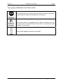
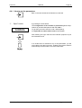
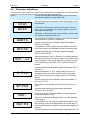
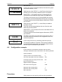
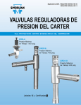
User's manual
Digital Indicator
D122.PA
Edition of standards 2010, software version 1.1.3, Rev.1
User’s manual for indicators
D122.PA.7.0.0
D122.PA.7.0.3K
D122.PA
2 Operation instructions
Page 2
Table of contents
1
Operation instruction for Explosion protected device ................................................................4
2
Digital Indicator D122.PA ...............................................................................................................5
2.1
Field housing for dust ex area ...................................................................................................5
2.2
Short description ........................................................................................................................5
2.3
2.3.1
2.3.2
.Features overview.....................................................................................................................5
Basic functions ....................................................................................................................5
Option: three channel monitoring Options ..........................................................................5
2.4
Conformity with Standards .........................................................................................................6
3
Installation and Connection ...........................................................................................................7
3.1
Field housing D122.PA / FF .......................................................................................................7
3.2
Connection D122 with field housing ..........................................................................................7
3.3
3.3.1
3.3.2
How to connect the calbe shield ................................................................................................8
Default parameters .............................................................................................................9
Ex works settings – Device reset........................................................................................9
4
Operating manual ..........................................................................................................................10
4.1
Front view.................................................................................................................................10
4.2
Keyboard ..................................................................................................................................10
4.3
LED Indications ........................................................................................................................11
4.4
4.4.1
Configuration ............................................................................................................................11
How to set the parameters ...............................................................................................12
4.5
Parameter definitions ...............................................................................................................13
4.6
Configuration example .............................................................................................................14
5
Annex .............................................................................................................................................17
5.1
Specifications ...........................................................................................................................17
5.2
Marking ....................................................................................................................................17
5.3
Failure messages .....................................................................................................................18
5.4
Type code ................................................................................................................................18
5.5
Dimensions ..............................................................................................................................19
5.6
Transport, Storing, Repairs und Disposal ................................................................................19
5.7
List of Parameters ....................................................................................................................20
Gönnheimer Elektronic GmbH
+49 (6321) 49919-0, Fax: -41
[email protected]
D122.PA
2 Operation instructions
Page 3
The symbols WARNING, CAUTION, NOTE
This symbol warns of a serious hazard. Failure to observe this warning may result in death or the destruction of property.
This symbol warns of a possible failure. Failure to observe this caution may result in the total failure of the device or the system or plant
to which it is connected.
This symbol highlights important information.
Gönnheimer Elektronic GmbH
+49 (6321) 49919-0, Fax: -41
[email protected]
D122.PA
1
2 Operation instructions
Page 4
Operation instruction for Explosion protected device
Application and Standards
This instruction manual applies to explosion-protected control panels of type of protection
types below. This apparatus is only to be used as defined and meets requirements of EN 60
079 particularly EN60 079-14 "electrical apparatus for potentiality explosive atmospheres".
Use this manual in hazardous locations, which are hazardous due to gases and vapours according to the explosion group and temperature class as stipulated on the type label. When
installing and operating the explosion protected distribution and control panels you should observe the respective nationally valid regulations and requirements.
General Instructions
The device has to have a back-up fuse as stipulated. The mains connection must have a sufficient short circuit current to ensure safe breaking of the fuse. To achieve an impeccable and
safety device operation, please take care for adept transportation, storage and mounting, as
well as accurate service and maintenance. Operation of this device should only be implemented by authorised persons and in strict accordance with local safety standards.
The electrical data on the type label and if applicable, the "special conditions" of the test certificate TÜV 99 ATEX 1488 are to be observed.
For outdoor installation it is recommended to protect the explosion protected distribution and
control panel against direct climatic influence, e.g. with a protective roof. The maximum ambient temperature is 40°C, if not stipulated otherwise.
Intrinsically Safe Circuits
Erection instructions in the testing certificates of intrinsically safe apparatus are to be observed. The electrical safety values stipulated on the type label must not be exceeded in the
intrinsically safe circuit. When interconnecting intrinsically safe circuits it is to be tested,
whether a voltage and/or current addition occurs. The intrinsic safety of interconnected circuits
is to be ensured. (EN 60079-14, section 12)
Safety Measures: to read and to comply
Work on electrical installations and apparatus in operation is generally forbidden in
hazardous locations, with the exception of intrinsically safe circuits. In special cases
work can be done on non-intrinsically safe circuits, on the condition that during the
duration of such work no explosive atmosphere exists. Only explosion protected
certified measuring instruments may be used to ensure that the apparatus is voltage-free. Grounding and short-circuiting may only be carried out, if there is no explosion hazard at the grounding or short circuit connection.
Danger of static charge!
Clean only with humid cloth!
Do not open when an explosive dust atmosphere is present!
Gönnheimer Elektronic GmbH
+49 (6321) 49919-0, Fax: -41
[email protected]
D122.PA
2 Operation instructions
2
Digital Indicator D122.PA
2.1
Field housing for dust ex area
Page 5
The digital indicator D122.PA.7.x.x is suitable for dust ex- area Zone 21 and 22.
2.2
Short description
The digital indicator D122.PA/FF operates as an indicator for process data in a Profibus PA
or field bus foundation H1 network.
The indicator behaves as a “Listener”, i.e. it does not appear in the bus as a participant with
an own address. It separates a programmed field bus address and indicates the value of this
address.
The advantage of this conception is that the D122.PA/FF must not be initialized by the bus
master and does not in-crease bus traffic. The programming of the address can be done by
the front side keyboard and is code word protected.
The D122.PA/FF indicates the process value of the sensor or actuator as a number of five
figures. It shows the process value status by limit value marks.
Beside the measured value, the display includes a 41- segment bar graph for fast trend observation, which can be scaled separately from the indicator value. The D122.PA/FF is built
into durable powder-coated aluminum housing
2.3
.Features
overview
2.3.1 Basic functions
• Gas- and dust Ex- protection
• 5-digits 7-segment LCD,
• 30 mm figure height
• Bargraph for fast trend observation, limit bargraph
• Powder coated (RAL 7035) aluminum housing, protection class IP66
• Ex- protection according FISCO model
Housings
• Field housing, protection class IP 65
Ergonomy
• µ-Processor technology for extensive configuration
• Scaleable by keyboard and display, without any reference current
• Separately scaleable bargraph (Zoom)
• Present value control button
• Keeps the configuration by turn off
• Ability to change configuration during operation
• Exchangeable dimension signs
2.3.2 Option: three channel monitoring Options
• Additional limit bargraph
• Field housing with additional (2nd) PG-Connector
Gönnheimer Elektronic GmbH
+49 (6321) 49919-0, Fax: -41
[email protected]
D122.PA
2.4
2 Operation instructions
Page 6
Conformity with Standards
The explosion proof indicators type D122 meets requirements of listed standards in the attachment
(Declaration of conformity). They were developed, manufactured and tested in accordance with stateof-the-art engineering practice and ISO9001:2008.
Gönnheimer Elektronic GmbH
+49 (6321) 49919-0, Fax: -41
[email protected]
D122.PA
3 Installation and Connection
3
Installation and Connection
3.1
Field housing D122.PA / FF
Page 7
When mounting the housing box on a wall, be sure that it is securely supported by anchoring the screws into a stud or other solid surface.
How to insert
the Dimensionsymbol
3.2
First, cut the desired dimension symbol out of the set. Then pull off the four
screws of the cap and remove the cap from the housing.
Now push the prepared dimension-symbol into the dimension-symbol-slot.
Make sure that the symbol is facing the front.
The dimension-symbol-slot lies below the display, on the internal side of the
cap.
Finally replace the cup on the housing.
Devices with option 3 channel (D122.x.7.0.3K) have a slot for dimension
symbol stripe in the front cup.
Connection D122 with field housing
The terminals of the indicators with field housing are inside. The placement of
the terminals is shown at the following figures.
Figure 1 shows the terminals of the indicator D122.A.5. Fehler! Verweisquelle konnte nicht gefunden werden. shows the terminals of the indicator
D122.A.6.
The terminals 5, 6 and 7,8 are absent by indicators without alarm monitoring.
Connect the indicator exclusive to an intrinsically
safe Profibus.
With danger by static loading the housing is to be
grounded.
Figure 1: Terminals of the indicator D122
Gönnheimer Elektronic GmbH
+49 (6321) 49919-0, Fax: -41
[email protected]
D122.PA
3 Installation and Connection
Page 8
The screen of the lead must be leading connected
with the screw connection. With the employment
within the highly combustible range the housing
must be connected by the external grounding connection with the potential equalization. (EN 6007914, exp. 12.2.2.3). Necessary repeated dung may
take place only capacitively. (EN 60079-14, exp.
12.2.2.3c)
Regard the terminal maximum values of the attached EC- type certificate TÜV 99 ATEX 1488 .
3.3
How to connect the calbe shield
See the following figure to connect the cable shield correctly to the metal gland.
After connecting, a display test (all segments of the display are turned on)
appears immediate during one second. Thereupon the display shows the
software version of the indicator.
Gönnheimer Elektronic GmbH
+49 (6321) 49919-0, Fax: -41
[email protected]
D122.PA
3 Installation and Connection
Page 9
3.3.1 Default parameters
The following parameters are active ex works:
Option:
The colored fields are for he three channel option only (-3K)
Quantity of the indicated channels
Chan
1
Automatic channel rolling
Auto
No
Field bus address
Addr.1
Addr.2
Addr.3
0
Offset (location of the indicator value)
OFFS1
OFFS2
OFFS3
1
A-show the in and/or the output data of
the bus of Masters
OUT. I1
OUT I2
OUT I3
In ‚
Exchanges that more highly and low
order byte of the data items
SfL1
SFL2
SFL3
No
Right-of-comma positions
DP.PO1
DP.PO2
DP.PO3
1
Display the bar graph?
BAR
Yes
Max value for the bar graph
BAR H1
BAR H2
BAR H3
100
Display the status- bar graph?
STATU
Yes
Measured value scaling factor
SFAC1
SFAC2
SFAC3
1,000
Measured value scaling offset
SOFS1
SOFS2
SOFS3
0,0
Menu password
CODE
0001
Menu- End
END
/
3.3.2 Ex works settings – Device reset
Press the Enter- and Right-button during the start sequence to
reactivate the default parameters. (Hardware-Reset)
A reset activates also the ex works calibration.
Gönnheimer Elektronic GmbH
+49 (6321) 49919-0, Fax: -41
[email protected]
D122.PA
4 Manual
4
Operating manual
4.1
Front view
Page 10
SET
5 Figure display
4
mA
20
Min
Max
Bargraph for actual value
Bargraph status information
4.2
Keyboard
On the front side of the indicator are tree buttons with several function symbols. With these tree buttons, the user can activate each function and enter all parameters for any individual setting.
The buttons are named by their functions:
Enter-button
Pressing the enter-button starts the input menu.
In general, the enter-button activates the menu item or accepts the manipulated value of a parameter.
Up-button
Functions of the up-button are:
1. Display the status byte
2. modification of the selected figure
3. pass menu items
Right-button
Functions of the right-button are:
1. Switch forward the displayed channel1
2. select figures
3. pass menu items
1
For three channel option only (122.PA.7.0.3K)
Gönnheimer Elektronic GmbH
+49 (6321) 49919-0, Fax: -41
[email protected]
D122.PA
4.3
4 Manual
Page 11
LED Indications
The D122.PA has up to 3 LED indicators. Using a 3 channels device D122.PA.7.0.3K the LED indicates the actual channel und the associated physical unit.
Further more the LED light has the following meaning:
4.4
LED- Status
Denotation
On (green )
This channel is active. Data is clearly received and indicated
Blinking
The D122 could not find bus data on the reselected bus address. See also “Error C”
Off
This channel is not indicated
Configuration
It is easy to set the parameters and change the configuration of the indicator. The parameters are
logically grouped by a menu structure. See also the appropriate flow diagram in the appendix.
)
Normal state
)
Status byte
After connecting, the indicator D122 starts to initialise its configuration. The configuration data is stored in an internal EEPROM
due to the previous run. By the first start, the D122 indicator initialises the default configuration.
Directly past starting sequence the indicator begins to display the
measured current digital and analogous on the bargraph. This
state is called the ‘normal state’ of the D122 and the indicator is
also ready for inputs.
Pressing and holding the up-button (current control button) the
display shows the status byte.
Gönnheimer Elektronic GmbH
+49 (6321) 49919-0, Fax: -41
[email protected]
D122.PA
4 Manual
Page 12
4.4.1 How to set the parameters
Back in the normal state of the indicator we start the
)
Input menu
CodeI
by pressing the enter-button.
The configuration of the indicator is protected against manipulations by unauthorized persons with the code 1.
To get the input menu enter the code 1 default [0001].
It’s impossible to switch off the code 1 interrogation.
After entering the right code word the indicator proposes to join
the Parameter menu
If an invalid value is entered for any of the parameters, you will
not be able to quit the input menu. Instead, the program switches
automatically into edit mode to the found valid value.
Gönnheimer Elektronic GmbH
+49 (6321) 49919-0, Fax: -41
[email protected]
D122.PA
4.5
4 Manual
Page 13
Parameter definitions
The parameters can be shown on 7 segment announcements only simplistically. The following listing
shows the full name and values of the parameters and adds an explanation:
Option:
The colored deposited fields are valid only for announce-
ment devices with the 3-canal Opion.3K:
Chan
After the Enter key was pressed, enter the quantity (1-3) of
the channels.
Auto
If more than one channel should be indicated, is able by
auto = yes - an automatic rolling (delay approx. 4 sec.) of
the canals are activated.
Otherwise, a channel persists on the display, until the operator switches manually to the next.
Addr1
The parameter bus address appears. Here the bus address,
which should be „listened“, is displayed.
If several channels were activated, appear afterwards
"Addr2" and "Addr3".
OFFS1
The parameter "Offset" gives the index (offset) of the first
byte of the value to be indicated from the conceiving data.
If several channels were activated, appear afterwards
"OFFS2" and "OFFS3".
OUT..I1
With the parameter "Out I1" (Data out 1) it defined whether
the dates of receipt or the source data of the Profibus slave
will be indicated. (The receipt data is from master to slave)
"In D" shows the source data, "Out D" gives the dates of
receipt.
If several canals were activated, appear afterwards "Out 2"
and "Out 3".
S FL1
With the parameter "S. FL1" (Swap Float) it is to be exchanged possibly the valence of both bytes in the data
word. This is necessary according to use of the Profibus
Slaves.
If several channels were activated, appear afterwards "S.
FL2" and "S. FL.3"
dP.PO1
bAr.
bar.H1
The position of the decimal point is fixed with this menu
point.
If several canals were activated appear afterwards
"dP.Pos2" and "dP.Pos3".
In this menu point it is defined whether values bargraph
should be indicated, or not.
„Bar= Yes“ indicates the Bargrah; with „bar = No“ appears
no bar graph.
If in precede menu point the bar graph was activeted, now
the maximum value of the Bargraphs (= bar graph High 1)
must be defined with all canals to scale the bar graphs customised.
If several canals were activated appear afterwards „bar. H2“
Gönnheimer Elektronic GmbH
+49 (6321) 49919-0, Fax: -41
[email protected]
D122.PA
4 Manual
Page 14
and „bar. H3“.
STATU
SFAC1
In this menu point it is defined whether the status bar graph
should be indicated, or not.
With the menu item "SFAC1" (= data Factor) the factor is
defined by him the actually indicated value is multiplied.
With SFAC1 = 10.0 appears around 10 times bigger announcement value than the value read in the data word.
The factor can become up to 3 figures behind the comma,
the indication scrolls automatically with the input to the left.
If several canals were activated appear afterwards "SFAC2"
and "SFAC3".
SOFF1
With the menu item "SOFF1" (= data offset) the additive
constant is fixed.
Then the announcement displays the sum from the read
data value and the SOFF1.
With SOFF1 =-10,0 is drawn off from the read data word 10,
before it is indicated.
If several canals were activated appear afterwards „SOFF2
and "SOFF3".
COdE
End
4.6
The Menu-code-word ex works "0001" can become here a
new one to deny the access to the configuration menu unauthorized persons.
Leave finally the menu by confirming with the input key.
The working condition is restored. The inputs are effective
immediately and remain after one clamping of the D122 of
the bus (D122 is switched off) are stored.
Configuration example
By the example of a temperature indication with limit value
warning the parameter input is described in the following attitudes
Field bus address
41
Offset (Location of the indicator value)
0
Show the output data of the bus of Masters
Out
Exchanges that more highly and low order
byte of the data items
NO
Right-of-comma positions
2
Max value for the bar graph
5000
Measured value scaling factor
1
Measured value scaling offset
0
Menu password
0001
Procedure:
With pressure on the input key will leave the operational
Gönnheimer Elektronic GmbH
+49 (6321) 49919-0, Fax: -41
[email protected]
D122.PA
4 Manual
COdE
Page 15
status indicator and activated input the menu.
The password Nr.1 is queried.
The factory-installed stopped password Nr.1 reads [0001].
Enter the password using the arrow keys.
Subsequently, the input key presses.
Measured value and bar graph scaling:
ADDR
The parameter bus address appears.
The input key to the input presses.
_002
Below the sign a flashing bar appears. By operation the to
the right-groped is selected the number which can be
changed and increased with the upward-groped in the value
by unity. With this proceeding the address 41t is entered.
The input is locked through pressures of the input key.
OFFSE
The next parameter „offset “is also passed with the
UP- key.
Out IN
The next parameter „Display In or Output data “is also passed
with the UP- key.
SFLO
The next parameter „Swap-Float“ is also passed with the UPkey.
DP.Po1
The decimal point so adjusted that two right-of-comma
positions are indicated.
The input is locked through pressures of the input key.
bAr.H1
STATU
SFAC1
Gönnheimer Elektronic GmbH
Enter the value “5000” to the upper bargraph scaling range
Press the right-button to select the next figure.
The next parameter „Scaling-Factor“ is also passed with the
right key.
+49 (6321) 49919-0, Fax: -41
[email protected]
D122.PA
4 Manual
Page 16
SOFF1
The next parameter „Offset-Factor“ is also passed with the right
key.
COdE
The last parameter „Set codes“ is also passed with the right key.
End
Finally quit the scale menu hitting the enter-button.
The indicator is back in normal state. The changes are immediately active and will be stored after turn off (disconnecting the indicator).
If an invalid value is entered for any of the parameters, you will
not be able to quit the input menu. Instead, the program switches
automatically into edit mode to the found valid value.
Gönnheimer Elektronic GmbH
+49 (6321) 49919-0, Fax: -41
[email protected]
D122.PA
5 Annex
5
Annex
5.1
Specifications
General
Page 17
Field indicator
D122.PA
Ex- protection
II 2 (1) G, Ex ia IIC T6 Gb
II 2 D, Ex tb IIIC IP65 T 70°C Db
Ui = 30 V
Ii = 660 mA
Pi = 1,6 W
Ci = 0 F, Li = 0 H
Ex- limits
FISCO- conformity
EC- type certificate
TÜV 99 ATEX 1488
Ambient temperature Ta
-10°C ...+45°C at T6.
-10°C ...+60°C at T5
-10°C ...+65°C at II 2 D
Devices for -20°C on demand
Type
Field housing
Protection class
IP 66 according to IEC 60529
Dimensions HxWxD [mm]
140 x 140 x 71
Material
Aluminum
Weight
900 g
Color
RAL 7035
LCD
5-stellige LCD-Seven-Segment
Figure height
30mm
Display range
-9999 ... +99999
Dimension symbols
Selectable
Decimal points
Selectable
Bargraph
41 Segments
Limit- monitoring
Limit set points
Electric
Power supply
None – power over bus (9 ..30V)
Specifications
Power cunsumption (Bus)
< 10 mA
Status byte monitoring
Display of the actual status byte
Housing
Display
5.2
Marking
Marking according to 50014 ff
Marking according to EN 60079 :2010
D122.x.7.x.0
D122.x.7.x.MU
II 2 G; EEx ia IIC T6 at Ta < 45°C
II 2 G; EEx ia IIC T5 at Ta < 60°C
II 2 D; Ex IP65 T70°C
II 2 G; Ex ia IIC T6 Gb at Ta < 45°C
II 2 G; Ex ia IIC T5 Gb at Ta < 60°C
II 2 D; Ex tb IIIC IP65 T70°C Db
D122.x.7.x.BM
II 2 G; EEx ia [ib] IIC T6 at Ta < 45°C
II 2 G; EEx ia [ib] IIC T5 at Ta < 60°C
II 2 D; Ex IP65 T 70°C
II 2 G; Ex ia [ib] IIC T6 Gb at Ta < 45°C
II 2 G; Ex ia [ib] IIC T5 Gb atTa < 60°C
II 2 D; Ex tb IIIC IP65 T70°C Db
0044
Gönnheimer Elektronic GmbH
+49 (6321) 49919-0, Fax: -41
[email protected]
D122.PA
5.3
5 Annex
Failure messages
Message
5.4
Page 18
Symptom
Bug-fix
Err_E
“EEPROM Error, - corrupted Turn off an turn on the device, if the
data in EEPROM detected
fault remains, send the device back to
Gönnheimer
Err_C
The D122 can not find data
on the pre selected bus
address
Verify the bus address
Type code
Device series D122 .
.
.
Device: Indicator .................................................................. .A
Indicator with curve fitting option ................................ .AS
Profibus PA indicator3 ................................................ .PA
Field bus foundation3 ................................................. .FF
Totalizer ...................................................................... .Z
Transmitter software .................................................. .T
Housing:
Control panel housing 48 x 96 mm .........................
Control panel housing 72 x 144 mm ......................
Field housing (30 mm figure height) ......................
Field housing (50 mm figure height) .......................
Aluminum field housing (30 mm figure height) .......
Digital output:
.0
.3
.5
.6
.7
without ................................................................
with 2 digital outputs ...........................................
with reset input and pulse output ........................
.0
.2
.3
Additional option:
Internal zener barrier1 .................................................................................... .BM
Internal two wire readings recorder² .............................................................. .MU
Display of 3 measure values........................................................................... .3K
1: Not suitable for D122.x.0.x.x
2: For flied housings only, a combination with internal zener barrier (.BM) is not possible
3: The field bus indicators are only in aluminum field housing available
Gönnheimer Elektronic GmbH
+49 (6321) 49919-0, Fax: -41
[email protected]
D122.PA
5.5
5 Annex
Page 19
Dimensions
(total height)
M16 x 1,5
Figure 2: Field housing
5.6
Transport, Storing, Repairs und Disposal
Transport
Vibration-free in origin package, do not pitch, handle carefully
Storing
Store the device dry, inside of the origin package
Disposal
When the explosion proof multipurpose distribution, switching and control
units are eventually disposed of, the national regulations governing the disposal of waste materials in the country concerned must be rigorously observed.
Defective parts may only be replaced by the Manufacturer or by personnel
specially trained and supervised by the Manufacturer. Only genuine spare
parts from the Manufacturer may be fitted.
Repairs
Gönnheimer Elektronic GmbH
+49 (6321) 49919-0, Fax: -41
[email protected]
D122.PA
5.7
5 Annex
Page 20
List of Parameters
The customer is free to use this chart for archiving the parameters of his indicator D122.PA
The grey deposited fields are valid only for indicator devices with the 3-canal option.3K:
Description
Display
Number of the indicated canals (channel)
Chan
Automatic canal wide circuit
Auto
Field coach address (n)
Addr.1
Addr.2
Addr.3
Value
OFFS1
Index (offset) of the first byte of the value
to be indicated from the conceiving benefit OFFS2
OFFS3
data
Display output or input data.
OUT. I1
OUT I2
OUT I3
Exchange of the higher and down valued
bytes of the Float values
SfL1
SFL2
SFL3
Post comma places, canal fix
DP.PO1
DP.PO2
DP.PO3
Should the bar graph be indicated?
BAR
Maximum for the bar graph
BAR H1
BAR H2
BAR H3
Should the status bar graph be indicated?
STATU
Scale factor factor
SFAC1
SFAC2
SFAC3
Offset
SOFS1
SOFS2
SOFS3
Menu-code -word
CODE
Menu-end
END
Gönnheimer Elektronic GmbH
+49 (6321) 49919-0, Fax: -41
[email protected]